- Table of Contents
- Related Documents
-
| Title | Size | Download |
|---|---|---|
| 02-Product Cases | 735.66 KB |
Insufficient resources for configuring VLAN termination
Symptom
When you are configuring VLAN termination on a Layer 3 aggregate subinterface, the device prompts that the resources are insufficient as follows:
[Sysname-Route-Aggregation1.1000] vlan-type dot1q vid 1000 to 1500 second-dot1q 3000 to 3300
Not enough resources to complete the operation.
Troubleshooting procedure
1. Based on the prompt message "Not enough resources to complete the operation," you can determine that the command failed to be issued due to insufficient system resources.
2. Display the cards in the device.
<Sysname> display device
Slot No. Brd Type Brd Status Software Version
0 AAA Master TEMP
1 NONE Absent NONE
2 BBB Normal TEMP
3 NONE Absent NONE
4 NONE Absent NONE
5 NONE Absent NONE
6 CCC Normal TEMP
7 NONE Absent NONE
8 NONE Absent NONE
9 NONE Absent NONE
NOTE: The preceding output is only an example and does not reflect the actual software or hardware information of the device.
3. To obtain the specifications for VLAN termination entries on the card in slot 2, contact Technical Support.
4. Calculate the number of VLAN termination entries for a Layer 3 Ethernet/aggregate subinterface as follows:
The number of physical interfaces in a Layer 3 Ethernet/aggregate subinterface × the number of outer tags × the number of inner tags. In this example, the number of VLAN termination entries for a Layer 3 aggregate subinterface is 600000 (600K) = 4 × (1500-1000) × (3300-3000), which exceeds the specifications supported by the card in slot 2.
5. You can draw a conclusion that the number of VLAN termination entries configured on the Layer 3 aggregate subinterface exceeds the specifications.
Root cause
The number of VLAN termination entries configured exceeds the specifications supported by the card. As a result, VLAN termination cannot be configured.
Solution
Since this issue is caused by card specifications, optimize the network to ensure that the number of VLAN termination entries configured on the Layer 3 aggregate subinterface stays within the specifications.
If a device has multiple Layer 3 aggregate subinterfaces, the total number of VLAN termination entries for all Layer 3 aggregate subinterfaces to which the physical interfaces on the same card belong cannot exceed the VLAN termination entry specifications for that card.
Software upgrade failure caused by a large version gap
Symptom
After you execute the boot-loader file command and reboot the device, the following problems might occur due to a large gap between the old and new software versions:
· The device starts up and operates correctly, but the running software version is still the old version.
· The device fails to start up.
Troubleshooting procedure
Correct upgrade procedure when the old and new software versions have a large version gap
1. Use FTP or TFTP to transfer the upgrade image file to the root directory of a file system. (Details not shown.)
2. Use the display version command to view the current BootWare image version.
<H3C> display version
H3C Comware Software, Version 7.1.048, Release 7143
Copyright (c) 2004-2014 Hangzhou H3C Tech. Co., Ltd. All rights reserved.
H3C CR16010-F uptime is 0 weeks, 0 days, 0 hours, 28 minutes
Last reboot reason : USER reboot
Boot image: cfa0:/CR16000-F-CMW710-BOOT-R7143.bin
Boot image version: 7.1.048, Release 7143
Compiled Nov 18 2014 17:07:41
System image: cfa0:/CR16000-F-CMW710-SYSTEM-R7143.bin
System image version: 7.1.048, Release 7143
Compiled Nov 18 2014 17:07:41
MPU(M) 0:
Uptime is 0 weeks,0 days,0 hours,28 minutes
BOARD TYPE: SR07SRPUB1
DRAM: 4096M bytes
CFCARD: 4002M bytes
PCB 1 Version: VER.A
Bootrom Version: 116
CPLD 1 Version: 001
CPLD 2 Version: 001
Release Version: H3C CR16010-F-7143
Patch Version : None
Reboot Cause : UserReboot
Number of Exist Subcards: 0
LPU 3:
Uptime is 0 weeks,0 days,0 hours,26 minutes
BOARD TYPE: MPE-1104
DRAM: 2048M bytes
PCB 1 Version: VER.A
PCB 2 Version: VER.A
Bootrom Version: 124
CPLD 1 Version: 001
Release Version: H3C CR16010-F-7143
Patch Version : None
Reboot Cause : UserReboot
Number of Exist Subcards: 4
Subcard 1 :
Exist : N
Subcard 2 :
Exist : Y
Type : MIC-GP8L
PCB : Ver.A
Number of Cpld: 1
Cpld 0:
SoftWare : 001
Number of Fpga: 0
Subcard 3 :
Exist : N
Subcard 4 :
Exist : N
3. See the table for IPE image sizes supported by different BootWare versions.
|
BootWare versions |
Description |
|
1.12 and earlier |
256 MB |
|
1.13 to 1.38 |
512 MB |
|
1.38 to latest |
1 GB |
4. Select an upgrade method according to the size of the IPE image file.
¡ If the IPE image size does not exceed the maximum size supported by the current BootWare version, use the boot-loader file command to specify startup image files.
¡ If the IPE image size exceeds the maximum size supported by the current BootWare version, first use the bootrom update command to load the latest BootWare image and then use the boot-loader file command to specify startup image files.
5. Load the latest BootWare image.
# Use the bootrom update command to load the latest BootWare image.
<Sysname> bootrom update file cfa0:/CR16000-F-CMW710-BOOT-NEW.bin slot 1
This command will update the Boot ROM file on the specified board(s), Continue? [Y/N]:y
Now updating the Boot ROM, please wait...
.............Done.
# Reboot the device.
<Sysname> reboot
Start to check configuration with next startup configuration file, please wait..
.......DONE!
Current configuration may be lost after the reboot, save current configuration?
[Y/N]:y
Please input the file name(*.cfg)[cfa0:/config.cfg]
(To leave the existing filename unchanged, press the enter key):
cfa0:/spp.cfg exists, overwrite? [Y/N]:y
Validating file. Please wait...
Saved the current configuration to mainboard device successfully.
This command will reboot the device. Continue? [Y/N]:y
Now rebooting, please wait...
6. Use the boot-loader file command to specify startup image files.
<Sysname> boot-loader file cfa0:/CR16000-F.ipe all main
Verifying the file cfa0:/CR16000-F.ipe on slot 0...................................
...........Done.
H3C CR16010-F images in IPE:
CR16000-F-CMW710-BOOT-NEW.bin
CR16000-F-CMW710-SYSTEM-NEW.bin
This command will set the main startup software images. Continue? [Y/N]:y
Add images to slot 0.
File cfa0:/CR16000-F-CMW710-BOOT-NEW.bin already exists on slot 0.
Overwrite the existing files? [Y/N]:y
Decompressing file CR16000-F-CMW710-BOOT-NEW.bin to cfa0:/CR16000-F-CMW710-BOOT-E830
5.bin..Done.
Decompressing file CR16000-F-CMW710-SYSTEM-NEW.bin to cfa0:/CR16000-F-CMW710-SYSTEM-
E8305.bin...Done.
Verifying the file cfa0:/CR16000-F-CMW710-BOOT-NEW.bin on slot 0.....Done.
Verifying the file cfa0:/CR16000-F-CMW710-SYSTEM-NEW.bin on slot 0...............
...........................Done.
The images that have passed all examinations will be used as the main startup so
ftware images at the next reboot on slot 0.
Decompression completed.
Do you want to delete cfa0:/CR16000-F.ipe now? [Y/N]:n
7. Reboot the device.
<Sysname> reboot
Start to check configuration with next startup configuration file, please wait..
.......DONE!
Current configuration may be lost after the reboot, save current configuration?
[Y/N]:y
Please input the file name(*.cfg)[cfa0:/config.cfg]
(To leave the existing filename unchanged, press the enter key):
cfa0:/spp.cfg exists, overwrite? [Y/N]:y
Validating file. Please wait...
Saved the current configuration to mainboard device successfully.
This command will reboot the device. Continue? [Y/N]:y
Now rebooting, please wait...
Troubleshooting procedure when the device can start up
If the BootWare image is not loaded before specify the upgrade image file, execute the following steps:
1. Use FTP or TFTP to transfer the upgrade image file to the root directory of a file system. (Details not shown.)
2. Use the bootrom update command to load the BootWare image.
<Sysname> bootrom update file cfa0:/CR16000-F-CMW710-BOOT-NEW.bin slot 1
This command will update the Boot ROM file on the specified board(s), Continue? [Y/N]:y
Now updating the Boot ROM, please wait...
.............Done.
3. Reboot the device.
<Sysname> reboot
Start to check configuration with next startup configuration file, please wait..
.......DONE!
Current configuration may be lost after the reboot, save current configuration?
[Y/N]:y
Please input the file name(*.cfg)[cfa0:/config.cfg]
(To leave the existing filename unchanged, press the enter key):
cfa0:/spp.cfg exists, overwrite? [Y/N]:y
Validating file. Please wait...
Saved the current configuration to mainboard device successfully.
This command will reboot the device. Continue? [Y/N]:y
Now rebooting, please wait...
4. Use the boot-loader file command to specify startup image files.
<Sysname> boot-loader file cfa0:/CR16000-F.ipe all main
Verifying the file cfa0:/CR16000-F.ipe on slot 0...................................
...........Done.
H3C CR16010-F images in IPE:
CR16000-F-CMW710-BOOT-NEW.bin
CR16000-F-CMW710-SYSTEM-NEW.bin
This command will set the main startup software images. Continue? [Y/N]:y
Add images to slot 0.
File cfa0:/CR16000-F-CMW710-BOOT-NEW.bin already exists on slot 0.
Overwrite the existing files? [Y/N]:y
Decompressing file CR16000-F-CMW710-BOOT-NEW.bin to cfa0:/CR16000-F-CMW710-BOOT-E830
5.bin..Done.
Decompressing file CR16000-F-CMW710-SYSTEM-NEW.bin to cfa0:/CR16000-F-CMW710-SYSTEM-
E8305.bin...Done.
Verifying the file cfa0:/CR16000-F-CMW710-BOOT-NEW.bin on slot 0.....Done.
Verifying the file cfa0:/CR16000-F-CMW710-SYSTEM-NEW.bin on slot 0...............
...........................Done.
The images that have passed all examinations will be used as the main startup so
ftware images at the next reboot on slot 0.
Decompression completed.
Do you want to delete cfa0:/CR16000-F.ipe now? [Y/N]:n
5. Reboot the device.
<Sysname> reboot
Start to check configuration with next startup configuration file, please wait..
.......DONE!
Current configuration may be lost after the reboot, save current configuration?
[Y/N]:y
Please input the file name(*.cfg)[cfa0:/config.cfg]
(To leave the existing filename unchanged, press the enter key):
cfa0:/spp.cfg exists, overwrite? [Y/N]:y
Validating file. Please wait...
Saved the current configuration to mainboard device successfully.
This command will reboot the device. Continue? [Y/N]:y
Now rebooting, please wait...
Troubleshooting procedure when the device cannot start up
If the BootWare image is not loaded before specify the upgrade image file, execute the following steps:
1. Log in to the console port, and press Ctrl+B during device startup to access the BootWare menu. Enter 7 in the EXTEND-BOOTWARE menu.
==========================<EXTENDED-BOOTWARE MENU>==========================
|<1> Boot System |
|<2> Enter Serial SubMenu |
|<3> Enter Ethernet SubMenu |
|<4> File Control |
|<5> Restore to Factory Default Configuration |
|<6> Skip Current System Configuration |
|<7> BootWare Operation Menu |
|<8> Skip Authentication for Console Login |
|<9> Storage Device Operation |
|<0> Reboot |
============================================================================
Ctrl+C: Display Copyright
Ctrl+F: Format File System
Enter your choice(0-9): 7
2. Enter 4 to upgrade BootWare through the management Ethernet port.
=========================<BootWare Operation Menu>==========================
|Note:the operating device is cfa0 |
|<1> Backup Full BootWare |
|<2> Restore Full BootWare |
|<3> Update BootWare By Serial |
|<4> Update BootWare By Ethernet |
|<0> Exit To Main Menu |
============================================================================
Enter your choice(0-4): 4
3. Enter 4 to modify Ethernet parameters.
===================<BOOTWARE OPERATION ETHERNET SUB-MENU>===================
|<1> Update Full BootWare |
|<2> Update Extended BootWare |
|<3> Update Basic BootWare |
|<4> Modify Ethernet Parameter |
|<0> Exit To Main Menu |
============================================================================
Enter your choice(0-4): 4
==========================<ETHERNET PARAMETER SET>==========================
|Note: '.' = Clear field. |
| '-' = Go to previous field. |
| Ctrl+D = Quit. |
============================================================================
Protocol (FTP or TFTP) :tftp
Load File Name :CR16000-F.ipe
:CR16000-F-CMW710-BOOT-NEW.bin
Target File Name :CR16000-F.ipe
:CR16000-F-CMW710-BOOT-NEW.bin
Server IP Address :192.168.2.26
Local IP Address :192.168.2.88
Subnet Mask :255.255.255.0
Gateway IP Address :0.0.0.0
4. Enter 1 to upload the BootWare image.
===================<BOOTWARE OPERATION ETHERNET SUB-MENU>===================
|<1> Update Full BootWare |
|<2> Update Extended BootWare |
|<3> Update Basic BootWare |
|<4> Modify Ethernet Parameter |
|<0> Exit To Main Menu |
============================================================================
Enter your choice(0-4): 1
Loading.....................................................................
.............................................................Done.
41560064 bytes downloaded!
Updating Basic BootWare? [Y/N]Y
Updating Basic BootWare.........Done.
Updating Extended BootWare? [Y/N]Y
Updating Extended BootWare.........Done.
5. Reboot the device.
===================<BOOTWARE OPERATION ETHERNET SUB-MENU>===================
|<1> Update Full BootWare |
|<2> Update Extended BootWare |
|<3> Update Basic BootWare |
|<4> Modify Ethernet Parameter |
|<0> Exit To Main Menu |
============================================================================
Enter your choice(0-4): 0
=========================<BootWare Operation Menu>==========================
|Note:the operating device is cfa0 |
|<1> Backup Full BootWare |
|<2> Restore Full BootWare |
|<3> Update BootWare By Serial |
|<4> Update BootWare By Ethernet |
|<0> Exit To Main Menu |
============================================================================
Enter your choice(0-4): 0
==========================<EXTENDED-BOOTWARE MENU>==========================
|<1> Boot System |
|<2> Enter Serial SubMenu |
|<3> Enter Ethernet SubMenu |
|<4> File Control |
|<5> Restore to Factory Default Configuration |
|<6> Skip Current System Configuration |
|<7> BootWare Operation Menu |
|<8> Skip Authentication for Console Login |
|<9> Storage Device Operation |
|<0> Reboot |
============================================================================
Ctrl+C: Display Copyright
Ctrl+F: Format File System
Enter your choice(0-9): 0
6. After the device restarts, enter 3 to access the Ethernet submenu.
==========================<EXTENDED-BOOTWARE MENU>==========================
|<1> Boot System |
|<2> Enter Serial SubMenu |
|<3> Enter Ethernet SubMenu |
|<4> File Control |
|<5> Restore to Factory Default Configuration |
|<6> Skip Current System Configuration |
|<7> BootWare Operation Menu |
|<8> Skip Authentication for Console Login |
|<9> Storage Device Operation |
|<0> Reboot |
============================================================================
Ctrl+Z: Access EXTENDED ASSISTANT MENU
Ctrl+C: Display Copyright
Ctrl+F: Format File System
Enter your choice(0-9): 3
7. Enter 5 to modify Ethernet parameters.
==========================<Enter Ethernet SubMenu>==========================
|Note:the operating device is cfa0 |
|<1> Download Image Program To SDRAM And Run |
|<2> Update Main Image File |
|<3> Update Backup Image File |
|<4> Download Files(*.*) |
|<5> Modify Ethernet Parameter |
|<0> Exit To Main Menu |
|<Ensure The Parameter Be Modified Before Downloading!> |
============================================================================
Enter your choice(0-5): 5
==========================<ETHERNET PARAMETER SET>==========================
|Note: '.' = Clear field. |
| '-' = Go to previous field. |
| Ctrl+D = Quit. |
============================================================================
Protocol (FTP or TFTP) :tftp
Load File Name :CR16000-F-CMW710-BOOT-NEW.bin
:CR16000-F.ipe
Target File Name :CR16000-F-CMW710-BOOT-NEW.bin
:CR16000-F.ipe
Server IP Address :192.168.2.26
Local IP Address :192.168.2.88
Subnet Mask :255.255.255.0
Gateway IP Address :0.0.0.0
8. Enter 2 to load the main startup software images upon next startup.
==========================<Enter Ethernet SubMenu>==========================
|Note:the operating device is cfa0 |
|<1> Download Image Program To SDRAM And Run |
|<2> Update Main Image File |
|<3> Update Backup Image File |
|<4> Download Files(*.*) |
|<5> Modify Ethernet Parameter |
|<0> Exit To Main Menu |
|<Ensure The Parameter Be Modified Before Downloading!> |
============================================================================
Enter your choice(0-5): 2
Loading.....................................................................Done.
644700160 bytes downloaded!
The file is exist,will you overwrite it? [Y/N]Y
Image file CR16000-F-CMW710-BOOT-NEW.bin is self-decompressing...
Saving file cfa0:/CR16000-F-CMW710-BOOT-NEW.bin ........Done.
Image file CR16000-F-CMW710-SYSTEM-NEW.bin is self-decompressing...
Saving file cfa0:/CR16000-F-CMW710-SYSTEM-NEW.bin ........Done.
9. Enter 0 and 1 to load and run the new images. After the device restarts, the upgraded is complete.
==========================<Enter Ethernet SubMenu>==========================
|Note:the operating device is cfa0 |
|<1> Download Image Program To SDRAM And Run |
|<2> Update Main Image File |
|<3> Update Backup Image File |
|<4> Download Files(*.*) |
|<5> Modify Ethernet Parameter |
|<0> Exit To Main Menu |
|<Ensure The Parameter Be Modified Before Downloading!> |
============================================================================
Enter your choice(0-5): 0
==========================<EXTENDED-BOOTWARE MENU>==========================
|<1> Boot System |
|<2> Enter Serial SubMenu |
|<3> Enter Ethernet SubMenu |
|<4> File Control |
|<5> Restore to Factory Default Configuration |
|<6> Skip Current System Configuration |
|<7> BootWare Operation Menu |
|<8> Skip Authentication for Console Login |
|<9> Storage Device Operation |
|<0> Reboot |
============================================================================
Ctrl+Z: Access EXTENDED ASSISTANT MENU
Ctrl+C: Display Copyright
Ctrl+F: Format File System
Enter your choice(0-9): 1
Loading the main image files...
Loading file cfa0:/CR16000-F-CMW710-SYSTEM-NEW.bin.............Done.
Loading file cfa0:/CR16000-F-CMW710-BOOT-NEW.bin...........Done.
Image file cfa0:/CR16000-F-CMW710-BOOT-NEW.bin is self-decompressing......Done.
System image is starting...
Line con0 is available.
Press ENTER to get started.
******************************************************************************
* Copyright (c) 2004-2021 New H3C Technologies Co., Ltd. All rights reserved.*
* Without the owner's prior written consent, *
* no decompiling or reverse-engineering shall be allowed. *
******************************************************************************
Root cause
The size of the IPE image file of the new version exceeds the limit supported by the BootWare of the old version.
Solution
If the device can start up correctly, load the BootWare of the new version. If the device cannot start up, log in to the console port, and access the BootWare menu during device startup.
Deployment failure for collaboration between NQA and static routing
Symptom
After you configure NQA-Track-static routing collaboration, when the track entry changes to Negative state, the associated static route does not become invalid. As a result, route switchover cannot be correctly performed.
Troubleshooting procedure
1. View track entry state on the device. The track entry has changed to Negative state, which means the track state switchover is correct.
<Sysname> display track 2
Track ID: 2
State: Negative
Duration: 0 days 0 hours 1 minutes 18 seconds
Tracked object type: NQA
Notification delay: Positive 0, Negative 0 (in seconds)
Tracked object
NQA entry: admin admin2
Reaction: 2
Remote IP/URL: 192.168.1.5
Local IP: 183.207.34.81
Interface: --
2. View route information on the device. The associated static route does not become invalid, which means the collaboration between static routing and Track fails to take effect.
<Sysname> display ip routing-table vpn-instance JiaSu2
Destinations : 21 Routes : 21
Destination/Mask Proto Pre Cost NextHop Interface
0.0.0.0/0 Static 60 0 183.207.34.82 XGE3/1/5
0.0.0.0/32 Direct 0 0 127.0.0.1 InLoop0
…
Root cause
1. View the static route configuration. The device has three static routes associated with track entries. Only track entry 2 is reported as invalid, which cannot be displayed from the static route configuration.
<Sysname> display current-configuration | include route-static
ip route-static vpn-instance JiaSu1 0.0.0.0 0 183.207.34.98 preference 65 description Jiasu1-bei
ip route-static vpn-instance JiaSu1 0.0.0.0 0 183.207.34.74 description JiaSu1-zhu track 1
ip route-static vpn-instance JiaSu2 0.0.0.0 0 183.207.34.106 preference 65 description JiaSu2-bei
ip route-static vpn-instance JiaSu2 0.0.0.0 0 183.207.34.82 preference 30 description JiaSu2-zhu track 2
ip route-static vpn-instance JiaSu3 0.0.0.0 0 183.207.34.90 description JiaSu3-zhu track 3
ip route-static vpn-instance JiaSu3 0.0.0.0 0 183.207.34.114 preference 65 description Jiasu3-be
2. View information about track entry 2. The track entry state has changed for more one minute, and the associated module is not notified of the state change.
<Sysname> display track 2
Track ID: 2
State: Negative
Duration: 0 days 0 hours 1 minutes 18 seconds
Tracked object type: NQA
Notification delay: Positive 0, Negative 0 (in seconds)
Tracked object
NQA entry: admin admin2
Reaction: 2
Remote IP/URL: 192.168.1.5
Local IP: 183.207.34.81
Interface: --
3. Configure the collaboration between Track and static routing again, and the issue is located. If you configure description JiaSu2-zhu and then specify track entry 2, the whole JiaSu2-zhu track 2 string is taken as the description, and track entry 2 is not actually associated with the static route. As a result, the collaboration fails to take effect. All the three static routes configured in this way fail to be associated with their respective track entries.
<Sysname> system-view
[Sysname] ip route-static vpn-instance JiaSu2 0.0.0.0 0 183.207.34.82 description JiaSu2-zhu track 2 ?
TEXT Route description (up to 150 characters)
<cr>
Solution
Specify a track entry, and then configure a description for the static route. The collaboration between Track and static routing takes effect after you edit static route configuration as follows:
ip route-static vpn-instance JiaSu2 0.0.0.0 0 183.207.34.82 track 2 description JiaSu2-zhu
ip route-static vpn-instance JiaSu2 0.0.0.0 0 183.207.34.82 track 2 preference 30 description JiaSu2-zhu
ip route-static vpn-instance JiaSu3 0.0.0.0 0 183.207.34.90 track 3 description JiaSu3-zhu
Standby MPU startup failure caused by software version inconsistency between the active and standby MPUs
Symptom
After you install two MPUs on the device, the active MPU installed first starts up correctly but the standby MPU installed later remains in fault state.
Troubleshooting procedure
1. Identify whether the device has sufficient power. If the power is insufficient, increase the power for the device.
2. Remove the active MPU and restart the device by using only the standby MPU. The device starts up correctly and the standby MPU is in normal state.
3. Check the software version of the MPUs. The startup software version of the standby MPU in the previous step is different from that of the active MPU.
This indicates that the software version of the active MPU fails to be synchronized to the standby MPU.
Root cause
The active and standby MPUs use different startup software versions that have a significant version gap. As a result, the software version of the active MPU cannot be synchronized to the standby MPU, causing standby MPU startup failure.
If the active and standby MPUs have a small software version gap, the standby MPU can directly synchronize the software version from the active MPU.
Solution
Update the software version of the standby MPU to that of the active MPU.
OSPFv3 neighbor relationship establishment failure with a Huawei switch on P2P network
Symptom
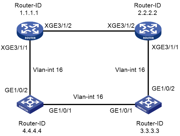
A CR16000-F device and a Huawei switch fail to establish an OSPFv3 neighbor relationship on a P2P network. The neighbor state remains Init. The network diagram is as shown in Figure 1.
Troubleshooting procedure
1. Execute the display ospfv3 peer command on the device whose router ID is 1.1.1.1 to view its neighbor information. The output shows that the device has established a neighbor relationship with another device whose router ID is 2.2.2.2, but the neighbor state remains Init.
<Sysname> display ospfv3 peer
OSPFv3 Process 1 with Router ID 1.1.1.1
Area: 0.0.0.0
-------------------------------------------------------------------------
Router ID Pri State Dead-Time InstID Interface
2.2.2.2 1 Init/ - 00:00:32 0 Vlan16
2. Execute the display ospfv3 peer command on the device whose router ID is 2.2.2.2 to view its neighbor information. The output shows that the device has established a neighbor relationship with the device whose router ID is 3.3.3.3, and the neighbor state is Full.
<Sysname> display ospfv3 peer
OSPFv3 Process 1 with Router ID 2.2.2.2
Area: 0.0.0.0
-------------------------------------------------------------------------
Router ID Pri State Dead-Time InstID Interface
3.3.3.3 1 Full/ - 00:00:32 0 Vlan16
3. Capture packets on device 2.2.2.2. The packet capture results show that the device receives Hello packets sent by the other three devices. Packet capture results on the other three devices show that only device 3.3.3.3 receives Hello packets from device 2.2.2.2. This issue prevents device 1.1.1.1 from establishing a neighbor relationship with device 2.2.2.2.
4. To resolve this issue, assign the interfaces connecting the CR16000-F device and the related Huawei switch to a VLAN different from the VLAN to which the interfaces connecting the Huawei switches belong.
Root cause
Layer 2 interfaces connecting the Huawei switches and the Layer 2 interfaces connecting the CR16000-F device and the related Huawei switch all belong to VLAN 16. As a result, all devices within the same broadcast domain. Since the network type for OSPFv3 is P2P, the establishment of OSPFv3 neighbor relationship depends on the order of receiving Hello packets.
As shown in Figure 1, device 1.1.1.1 attempts to establish a neighbor relationship with device 2.2.2.2. However, device 2.2.2.2 has already established a neighbor relationship with device 3.3.3.3. Consequently, device 1.1.1.1 cannot receive Hello packets from device 2.2.2.2, leaving the neighbor state as Init.
Solution
Divide the broadcast domain by assigning the interfaces connecting the CR16000-F device and a Huawei switch to a VLAN different from the VLAN to which the interfaces connecting the Huawei switches belong. Start an OSPFv3 process on the VLAN interfaces respectively. The CR16000-F device can then establish a neighbor relationship with the related Huawei switch.
BGP peer flapping
Symptom
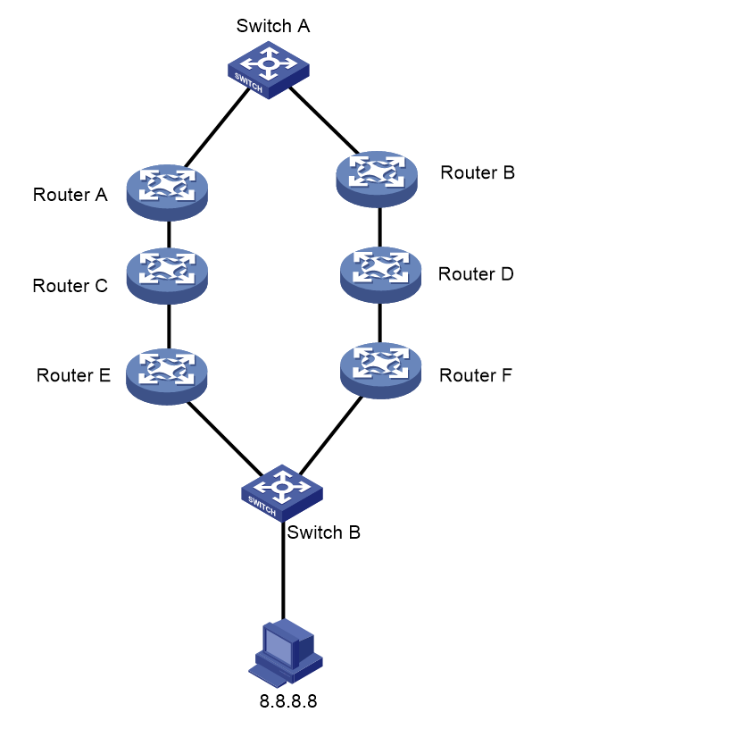
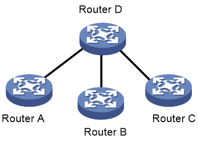
As shown in Figure 2, Router A is a route reflector. It establishes a BGP session with Router C via Router B. Both Router A and Router C are CR16000-F devices. Router B is a third-party device. During device deployment, the BGP peer session between Router A and Router C flaps repeatedly.

Troubleshooting procedure
1. Verify that all peer sessions of Router A are normal except for the peer session between Router A and Router C. This session is repeatedly re-established.
2. View the logfile. It prompts a session holdtime timeout error and the BGP state is changed from Established to Idle. After the BGP session is re-established, the BGP state transitions from OpenConfirm to Established. The BGP session is repeatedly terminated and re-established.
%Feb 4 12:24:47:654 2022 MPLS-RouterA-B-YueQ-10F-A02-PE BGP/5/BGP_STATE_CHANGED: BGP default.: 172.25.128.210 state has changed from ESTABLISHED to IDLE for a notification received: Hold Timer Expired/ErrSubCode Unspecified.
%Feb 4 12:24:49:819 2022 MPLS-RouterA-B-YueQ-10F-A02-PE BGP/5/BGP_STATE_CHANGED: BGP default.: 172.25.128.210 State is changed from OPENCONFIRM to ESTABLISHED.
3. Execute the ping command on Router A and Router C. They can access each other. The possible cause for this issue might be that Router B discards BGP messages. You can collect BGP debug information from Router A and Router C.
a. View BGP debug information on Router A. Router A transmits and receives keepalive messages.
*Feb 17 15:19:14:500 2022 MPLS-RouterA-B-YueQ-10F-A02-PE BGP/7/DEBUG: -MDC=1;
BGP.: 172.25.128.210 Send KEEPALIVE
Length: 19
%Feb 17 15:19:57:037 2022 MPLS-RouterA-B-YueQ-10F-A02-PE SSHS/5/SSHS_ACL_DENY: -MDC=1; The SSH Connection 61.240.202.41(ZJWS_INTERNET) request was denied according to ACL rules.
*Feb 17 15:20:08:829 2022 MPLS-RouterA-B-YueQ-10F-A02-PE BGP/7/DEBUG: -MDC=1;
BGP.: 172.25.128.210 Recv KEEPALIVE
Length: 19
*Feb 17 15:20:10:500 2022 MPLS-RouterA-B-YueQ-10F-A02-PE BGP/7/DEBUG: -MDC=1;
BGP_TIMER.: 172.25.128.210 KA Timer Expired.
*Feb 17 15:20:10:500 2022 MPLS-RouterA-B-YueQ-10F-A02-PE BGP/7/DEBUG: -MDC=1;
BGP.: 172.25.128.210 Send KEEPALIVE
Length: 19
b. View BGP debug information on Router C. Router C transmits keepalive messages, but does not receive keepalive messages.
Feb 17 15:20:07:314 2022 MPLS-RouterC-B-SD-1F-1-E10-RR BGP/7/DEBUG: -MDC=1;
BGP.: 172.25.128.174 Send KEEPALIVE
Length: 19
*Feb 17 15:21:01:314 2022 MPLS-RouterC-B-SD-1F-1-E10-RR BGP/7/DEBUG: -MDC=1;
BGP_TIMER.: 172.25.128.174 KA Timer Expired.
*Feb 17 15:21:01:314 2022 MPLS-RouterC-B-SD-1F-1-E10-RR BGP/7/DEBUG: -MDC=1;
BGP.: 172.25.128.174 Send KEEPALIVE
Length: 19
*Feb 17 15:21:18:314 2022 MPLS-RouterC-B-SD-1F-1-E10-RR BGP/7/DEBUG: -MDC=1;
BGP_TIMER.: 172.25.128.174 HD Timer Expired.
*Feb 17 15:21:18:314 2022 MPLS-RouterC-B-SD-1F-1-E10-RR BGP/7/DEBUG: -MDC=1;
BGP_TIMER.: 172.25.128.174 Restart Timer Created.
*Feb 17 15:21:18:315 2022 MPLS-RouterC-B-SD-1F-1-E10-RR BGP/7/DEBUG: -MDC=1;
BGP_TIMER.: 172.25.128.174 KA Timer Deleted.
*Feb 17 15:21:18:315 2022 MPLS-RouterC-B-SD-1F-1-E10-RR BGP/7/DEBUG: -MDC=1;
BGP_TIMER.: 172.25.128.174 HD Timer Deleted.
%Feb 17 15:21:18:315 2022 MPLS-RouterC-B-SD-1F-1-E10-RR BGP/5/BGP_STATE_CHANGED: -MDC=1;
BGP default.: 172.25.128.174 state has changed from ESTABLISHED to IDLE for hold timer expiration caused by peer device.
4. Further inspect the on-site settings. The default MTU for the interface was modified.
#
interface Route-Aggregation11
description To_SD_E10_ASR9k_BE11
mtu 1586
ip address 172.25.140.202 255.255.255.252
isis enable 100
isis circuit-type p2p
link-aggregation mode dynamic
mpls enable
#
5. View the BGP log. The BGP session is terminated every 18 seconds. This issue might be caused by packet fragmentation.
6. Use the ping command on Router A to ping Router C. Specify different ICMP echo request lengths (1472, 1500, 1558, and 1559 bytes) and disable Router A from fragmenting these ICMP echo requests. Router A cannot ping Router C if the specified ICMP echo request length is 1558 or 1559 bytes. It is found that Router B's MTU is 1586 bytes. Therefore, messages exceeding 1586 bytes will be discarded by Router B.
<RouterA> ping -f -s 1472 172.25.128.174 172.25.128.210
<RouterA> ping -f -s 1500 172.25.128.174 172.25.128.210
<RouterA> ping -f -s 1558 172.25.128.174 172.25.128.210
<RouterA> ping -f -s 1559 172.25.128.174 172.25.128.210
7. To avoid packet discarding by Router B, set a smaller TCP MSS or MTU. This operation makes TCP packet fragments smaller. As a best practice, set the TCP MSS to 1400. TCP MSS adjustment is required at only one end, because the two ends use the minimum TCP MSS for communication.
Root cause
Keepalive and update messages are transmitted during BGP session establishment. Router B discards the update messages of Router A because they exceed the MTU of Router B. As a result, Router C can receive the keepalive messages of Router A, but not the update messages of Router A, which causes the related TCP packets to be discarded due to discontiguous TCP sequence numbers. Router C only transmits keepalive messages and does not receive keepalive messages. Since the update messages of Router C do not exceed the MTU of Router B, Router A can transmit and receive keepalive messages.
Solution
Adjust the TCP MSS or MTU value for the local and remote devices, ensuring that their BGP TCP packet segments are smaller than the MTU of the intermediate device.
Packet filtering on an interface cannot control SSH login successfully
Symptom
The on-site network configuration is as follow:
· Two interconnected CR16014-F routers and two interconnected Router As of the same model, act as the WAN egress devices for a certain site. Each device has three WAN egress interfaces and one inter-device interconnect interface.
· In the inbound direction of all WAN egress interfaces on each device, the administrator the packet-filter command to block SSH login from the WAN network. That is, using an ACL to discard SSH packets with source addresses as public IPs and destination addresses as the device's loopback management interface address.
SSH packets received from two Router As are completely dropped. However, SSH packets received from two CR16014-F devices are not entirely dropped, allowing users to still log in to the devices via SSH from the WAN network.
Troubleshooting procedure
1. View detailed information about packet filtering configuration.
Verify that the configuration on the egress interfaces of Router As and CR16014-F routers on the WAN network is the same. Make sure the packet-filter command is executed on all the WAN egress interfaces and ACL rules used by packet filtering are correct.
Configure the following settings on all public interfaces of the devices:
interface HundredGigE4/0/3
port link-mode route
mtu 4470
ip address XXXX 255.255.255.252
isis enable 1
isis ipv6 enable 1
isis circuit-level level-2
isis circuit-type p2p
isis cost 5000
level-2 isis ipv6 cost 5000 level-2
isis authentication-mode md5 cipher c$3$3SxcYRonREfpUIE4pkhdkqFH1s8r7Jre9QnY
mpls enable
mpls ldp enable
ipv6 mtu 4470
packet-filter name DENY-XXX-SSH inbound
ipv6 address XXX/X
ipv6 address auto link-local
2. Execute the packet-filter command and specify the with the hardware-count keyword to enable packet counting statistics for ACL filtering. Execute the display packet-filter statistics interface command to display packet filtering statistics for all ACLs. The fields from the output include the following:
Totally 0 packets permitted, 7 packets denied
Totally 0% permitted, 100% denied
Packet capturing identifies that a total of 20 SSH packets were sent from the WAN network, among which seven packets were successfully matched and discarded by the packet filtering policy on the interface. The remaining 13 packets did not match the packet filtering policy. The deivce might have SSH packets forwarded to this device from other interfaces.
3. Execute the debugging ip packet command to enable IP packet debugging to search for SSH packets. The SSH packets from the device interconnect interfaces were sent to the CPU for processing. This indicates that the egress interfaces for the WAN egress interface have rejected SSH packets with the local loopback management interface address as the destination address, yet failed to block SSH packets with a destination address other than the local device.
4. The analysis upon the network configuration identifies that both the WAN egress interfaces and the device interconnect interfaces are deployed with MPLS. All WAN traffic passes through MPLS LSP to access the devices.
Root cause
If the device acts as the last hop on the LSP, SSH packets generally do not carry any MPLS label. In this case, packet filtering applied on the device's WAN egress interface can correctly match these IP packets.
If the device is not the last hop on the LSP, SSH packets might carry MPLS labels. In this case, packet filtering applied on the WAN egress interfaces of the device might not be able to match the MPLS-labeled SSH packets. As a result, the SSH packets with MPLS labels are forwarded through the interconnect interface to another device and are then processed by the CPU of that device.
In the current software version, the CR16014-F device does not support using ACL rules to match IP addresses and protocol port information for packets encapsulated with MPLS labels. This issue does not occur on Router As, because these routers support using ACL rules to match IP addresses and protocol port information for packets encapsulated with MPLS labels.
Solution
Configure packet filtering on interconnect interface of the CR16014-F devices to filter SSH packets completely.
Inconsistent round-trip paths due to BGP and OSPF route selection
Symptom
On a typical three-level network, as shown in Figure 3, Router A and Router B operates as level-1 core PEs and Switch A as the level-1 core CE. Router C and Router D operates as level-2 core devices, and Router E and Router F operates as level-3 core devices. Switch B operates as the level-3 core CE and connects to a site whose IP address is 8.8.8.8.
Switch B connects to the level-3 PEs through primary and backup links.
· The primary link is Router A <> Router C <> Router E. It passes routes to Router A via BGP and MPLS L3VPN. On Router A, BGP VPNv4 routes and OSPF routes are mutually redistributed. Finally, Router A passes the routes to Switch A via OSPF. Router A and Router E share the same OSPF domain ID, which is the default value of 0.
· The backup link connects Router B <> Router D <> Router F. Router F redistributes the static routes from the access layer into OSPF, and then passes the routes to Switch A via OSPF.
On the network, two OSPF processes exist: OSPF 1 runs on Router A, Switch A, Router B, and Router D, and OSPF 2 runs on Router D and Router F. On Router D, the two OSPF processes redistribute routes into each other.
On this network, traffic passes through the primary link when it operates correctly, and switches to the backup link upon a fault in the primary link. After the primary link recovers, the traffic is steered back to the primary link. The current issue is that traffic is not steered back to the primary link after the primary link recovers.
Troubleshooting procedure
|
|
NOTE: The following output information is for illustration only. |
1. View the route destined for site 8.8.8.8 in VPN instance 1.
<RouterA> display ip routing-table vpn-instance 1 8.8.8.8
Summary count : 1
Destination/Mask Proto Pre Cost NextHop Interface
8.8.8.8/32 BGP 255 2 6.6.6.6 XGE3/1/1
The output shows that the route to 8.8.8.8 is learned from BGP. The next hop address is the loopback address of Router C and the preference is 255.
2. View the LSDB information for OSPF 1 on Router A, and view the LSA corresponding to site 8.8.8.8.
<RouterA> display ospf 1 lsdb
OSPF Process 1 with Router ID 10.0.0.2
Link State Database
Area: 0.0.0.0
Type LinkState ID AdvRouter Age Len Sequence Metric
Router 10.0.0.2 10.0.0.2 669 36 80000003 0
Router 5.5.5.5 5.5.5.5 661 48 80000004 0
Router 1.1.1.1 1.1.1.1 660 60 80000007 0
Network 10.0.0.6 5.5.5.5 660 32 80000002 0
Network 10.0.0.2 10.0.0.2 669 32 80000002 0
Sum-Net 8.8.8.8 10.0.0.2 650 28 80000001 2
AS External Database
Type LinkState ID AdvRouter Age Len Sequence Metric
External 10.0.0.0 5.5.5.5 642 36 80000001 1
External 7.7.7.7 5.5.5.5 642 36 80000001 1
Route distinguisher: 1:6
Total number of routes: 1
Paths: 1 available, 1 best
BGP routing table information of 8.8.8.8/32:
From : 6.6.6.6 (6.6.6.6)
Rely nexthop : 10.0.0.10
Original nexthop: 6.6.6.6
OutLabel : 1279
Ext-Community : <OSPF Domain Id: 0.0.0.0:0>, <OSPF Router Id: 6.6.6.6:0:0>,
<OSPF AreaNum: 0.0.0.0 RouteType: 1 Option: 0>, <RT: 1:1>
RxPathID : 0x0
TxPathID : 0x0
AS-path : (null)
Origin : incomplete
Attribute value : MED 2, localpref 100, pref-val 0
State : valid, internal, best
IP precedence : N/A
QoS local ID : N/A
Traffic index : N/A
Site 8.8.8.8 has an LSA of the Sum-Net type, which means it is a Network Summary LSA (Type-3). Router A and Router E share the same OSPF domain ID, 0. The OSPF domain ID carried by the BGP VPNv4 route for site 8.8.8.8 is 0. When Router A redistributes the BGP VPNv4 route into OSPF, it advertises the route to Switch A in a Network Summary LSA (Type-3 LSA), because Router A's primary domain ID matches the OSPF domain ID in the route.
Router B has two LSAs for site 8.8.8.8, a Type-3 LSA from Router A in OSPF 1 and a Type-5 LSA from Router F in OSPF 2. The Type-3 LSA has a higher preference than the Type-5 LSA. Consequently, when Router B's two OSPF processes import routes from each other, the Type-3 LSA from OSPF 2 is active instead of the Type-5 LSA from OSPF 1. Router B advertises the Type-3 LSA to the backup link, and traffic is forwarded based on the Type-3 LSA, passing through the primary link.
3. On Router A, shut down and restore BGP peer sessions. Use the display ip routing-table command to display routes with destination address 8.8.8.8 in VPN instance 1.
<RouterA> display ip routing-table vpn 1 8.8.8.8
Summary count : 1
Destination/Mask Proto Pre Cost NextHop Interface
8.8.8.8/32 O_ASE2 150 1 10.0.0.1 XGE3/1/1
The output shows that the route for 8.8.8.8 is an OSPF route, not a BGP route. Router D redistributes this route as a Type-5 LSA, and traffic is forwarded via the backup link.
4. On Router A, execute the display ip routing-table command to display BGP VPNv4 routes destined for 8.8.8.8.
<RouterA> display bgp routing-table vpnv4
BGP local router ID is 2.2.2.2
Status codes: * - valid, > - best, d - dampened, h - history
s - suppressed, S - stale, i - internal, e - external
a - additional-path
Origin: i - IGP, e - EGP, ? - incomplete
Total number of routes from all PEs: 1
Route distinguisher: 1:2(1)
Total number of routes: 6
Network NextHop MED LocPrf PrefVal Path/Ogn
* > 1.1.1.1/32 10.0.0.1 2 32768 ?
* > 5.5.5.5/32 10.0.0.1 3 32768 ?
* > 7.7.7.7/32 10.0.0.1 2 32768 ?
* >i 8.8.8.8/32 6.6.6.6 2 100 0 ?
* > 10.0.0.0/20 10.0.0.1 2 32768 ?
* > 10.0.0.4/30 10.0.0.1 3 32768 ?
Route distinguisher: 1:6
Total number of routes: 1
Network NextHop MED LocPrf PrefVal Path/Ogn
* >i 8.8.8.8/32 6.6.6.6
The output shows that the BGP neighbor relationship has been successfully restored, but the traffic is not steered to the primary link.
5. On Router A, configure a routing policy to set the preference to 130 for routes destined for 8.8.8.8.
a. Create an IPv4 prefix list named p1 that only permits routes for 8.8.8.8/32 to pass.
<RouterA> system-view
[RouterA] ip prefix-list p1 permit 8.8.8.8 32
b. Create a routing policy named policy1 with a node sequence number of 10 and the match mode of permit. If traffic matches IPv4 prefix list p1, the routing policy sets the route preference to 130.
[RouterA] route-policy policy1 permit node 10
[RouterA-route-policy-policy1-10] if-match ip address prefix-list p1
[RouterA-route-policy-policy1-10] apply preference 130
6. View routes destined for site 8.8.8.8 on Router A.
<RouterA> display ip routing-table vpn-instance 1 8.8.8.8
Summary count : 1
Destination/Mask Proto Pre Cost NextHop Interface
8.8.8.8/32 BGP 130 2 6.6.6.6 XGE3/1/1
The output shows that the route for 8.8.8.8 has been restored to the BGP route, and traffic is forwarded through the primary link.
Root cause
If you configure the OSPF domain ID by using the domain-id command, the PE attaches the primary domain ID to the route as an extended community attribute when redistributing an OSPF route into BGP. The domain ID is passed to the remote PE. Upon receiving the BGP route, the remote PE compares the locally configured primary and secondary OSPF domain IDs with the OSPF domain ID carried in the route. If the primary or secondary domain ID matches the domain ID in the route and the route is an intra-area or inter-area route, the route is advertised to the CE as a Network Summary LSA (Type-3 LSA) when redistributed into OSPF. If the primary or secondary domain ID does not matches the domain ID in the route, it is advertised to the CE as either an AS External LSA (Type-5 LSA) or an NSSA External LSA (Type-7 LSA).
When the primary link operates correctly, two LSAs about site 8.8.8.8 exist on Router D, a Type-3 LSA from Router A in OSPF 1 and a Type-5 LSA from Router F in OSPF 2. The Type-3 LSA has a higher preference than the Type-5 LSA. As a result, when Router D's two OSPF processes import routes from each other, the Type-3 LSA introduced by OSPF 2 is active instead of the Type-5 LSA redistributed by OSPF 1. Router D advertises the Type-3 LSA to the backup link but not the Type-5 LSA to the primary link. Traffic is forwarded according to the Type-3 LSA, passing through the primary link.
When the BGP route fails, the Type-3 LSA is withdrawn. Router A learns the Type-5 LSA redistributed by Router D, directing traffic through the backup link. After the BGP route is restored, its default preference is 255. Since the OSPF route generated from the Type-5 LSA has a preference of 150, the OSPF route takes precedence over the BGP route, placing the BGP route in inactive state. As a result, traffic continues to pass through the backup link.
Solution
Configure a routing policy that modifies the preference for BGP routes destined for the site through, ensuring those BGP routes take precedence over OSPF routes. Traffic will be automatically switched from the backup link to the primary link when the BGP routes are restored.
Lack of interface numbers in traps corresponding to device interface up or down events
Symptom
After a device interface comes up or goes down, the trap that records the event does not contain the interface number.
%Nov 21 16:36:10:014 2017 Sysname SNMP/6/SNMP_NOTIFY: Notification linkDown(1.3.6.1.6.3.1.1.5.3) with ifIndex(1.3.6.1.2.1.2.2.1.1.610)=610;ifAdminStatus(1.3.6.1.2.1.2.2.1.7.610)=1;ifOperStatus(1.3.6.1.2.1.2.2.1.8.610)=2.
Troubleshooting procedure
1. View the trap corresponding to an interface down event on another device. The trap contains detailed interface information.
%Nov 21 16:15:00:954 2017 Sysname SNMP/6/SNMP_NOTIFY: Notification linkDown(1.3.6.1.6.3.1.1.5.3) with ifIndex(1.3.6.1.2.1.2.2.1.1.592)=592;ifAdminStatus(1.3.6.1.2.1.2.2.1.7.592)=1;ifOperStatus(1.3.6.1.2.1.2.2.1.8.592)=2.
%Nov 21 16:15:00:953 2017 Sysname SNMP/6/SNMP_NOTIFY: Notification hh3cIfPortDown(1.3.6.1.4.1.25506.2.40.3.0.6) with ifIndex(1.3.6.1.2.1.2.2.1.1.592)=592;ifDescr(1.3.6.1.2.1.2.2.1.2.592)=Ten-GigabitEthernet1/6/0/10.
2. The trap corresponding to an interface down event on the device lacks the detailed interface information, which prevents the monitoring system from detecting anomalies promptly.
%Nov 21 16:36:10:014 2017 Sysname SNMP/6/SNMP_NOTIFY: Notification linkDown(1.3.6.1.6.3.1.1.5.3) with ifIndex(1.3.6.1.2.1.2.2.1.1.610)=610;ifAdminStatus(1.3.6.1.2.1.2.2.1.7.610)=1;ifOperStatus(1.3.6.1.2.1.2.2.1.8.610)=2.
Root cause
By default, the device sends standard linkUp/linkDown notifications, which do not contain detailed interface information.
Solution
Execute the snmp-agent trap if-mib link extended command in system view to enable extended linkUp/linkDown notifications. The extended linkUp/linkDown notifications include both the standard linkUp/linkDown notifications and interface descriptions, which can help the administrator locate the issues quickly.
Before you enable extended linkUp/linkDown notifications, make sure the NMS supports the extended linkup and linkDown notifications. If the NMS does not support the extended linkup and linkDown notifications, the notifications cannot be parsed.
Communication failure on an interface inserted with the SFP-GE-LX-SM1310-D transceiver module on an MIC-XP20L interface card on the device
Symptom
After the SFP-GE-LX-SM1310-D GE transceiver module is inserted into an interface of the MIC-XP20L interface card on the device, the transceiver module has correct Tx and Rx power, but the interface cannot communicate properly.
Troubleshooting procedure
1. Obtain H3C CR16000-F Router Series Cards and Transceiver Modules Compatibility Matrixes from the H3C official website.
2. Verify that the MIC-XP20L interface card supports the SFP-GE-LX-SM1310-D transceiver module based on the document.
3. Identify whether the SFP-GE-LX-SM1310-D transceiver module is operating correctly.
Insert the transceiver module to an interface of a compatible card on another device, which indicates that the interface is in up state. Execute the loopback internal command to enable internal loopback testing on the Ethernet interface, which indicates that the corresponding interface is still in up state. Then, the SFP-GE-LX-SM1310-D transceiver module is operating correctly.
4. Execute the display transceiver interface and display interface commands to interface information on the SFP-GE-LX-SM1310-D GE transceiver module and MIC-XP20L interface card. The output shows that the interface on the MIC-XP20L interface card does not match the rate of the GE-LX-SM1310-D GE transceiver module.
Root cause
The communication failure occurs, because the interface on the MIC-XP20L interface card does not match the rate of the GE-LX-SM1310-D GE transceiver module.
Solution
Execute the using gigabit command to switch a 10GE interface on the MIC-XP20L interface card to a GE interface, the interface can communicate normally.
For other cards, execute the speed command to set the speed of an Ethernet interface. For more information about the using gigabit and speed commands, see Ethernet interface commands in H3C CR16000-F Routers Command Reference.
Failure to establish an IS-IS neighbor relationship between the device and Cisco N9000 with the same settings configured at both ends
Symptom
Although CR16000-F and Cisco N9000 use the same settings, they cannot establish an IS-IS neighbor relationship.
Troubleshooting procedure
1. Execute the debugging isis timer command on CR16000-F to enable IS-IS timer debugging. A Level-1 hello timer timeout error is prompted.
<Sysname> debugging isis adj-packet 1
*Mar 2 07:21:40:899 2022 H3C ISIS/7/ISISDBG: -MDC=1;
ISIS-1-TMR: Level-1 hello timer expired on the circuit GigabitEthernet3/1/1.
2. Execute the debugging isis adj-packet send command on CR16000-F to enable debugging IS-IS hello packet transmission. Hello packets are transmitted normally and their length is 1541.
<Sysname> debugging isis adj-packet send 1
*Mar 2 07:21:40:919 2022 H3C ISIS/7/ISISDBG: -MDC=1;
ISIS-1-ADJ: Send a Lan L1 Hello packet on circuit(GigabitEthernet3/1/1)
*Mar 2 07:21:40:920 2022 H3C ISIS/7/ISISDBG: -MDC=1;
ISIS-1-ADJ:
0000: 83 1b 01 06 10 01 00 00 02 00 00 00 00 00 59 00
0010: 1e 06 05 40 00 00 00 00 00 59 02 01 02 01 00 84
// 0x605 = 1541 (MTU=1541)
3. Execute the debugging isis adj-packet receive command on CR16000-F to enable debugging IS-IS hello packet reception. Hello packets are received normally and their length is 1527.
<Sysname> debugging isis adj-packet receive 1
*Mar 2 07:21:40:921 2022 H3C ISIS/7/ISISDBG: -MDC=1;
ISIS-1-ADJ: Receive a Lan L1 Hello packet from(0000.0000.0001) on circuit(GigabitEthernet3/1/1)
*Mar 2 07:21:40:922 2016 H3C ISIS/7/ISISDBG: -MDC=1;
ISIS-1-ADJ: Level-1 NBR(0000.0000.0001) two way pass.
*Mar 2 07:21:40:923 2022 H3C ISIS/7/ISISDBG: -MDC=1;
ISIS-1-ADJ:
0000: 83 1b 01 00 10 01 00 00 02 00 00 00 02 05 30 00
0010: 1e 05 f7 40 00 00 00 02 05 30 3d 81 01 cc d3 03
// 0x5f7 = 1527 (MTU=1527)
4. Execute the show isis interface command on Cisco N9000 to view its IS-IS configuration. The IS-IS interface MTU is 1527.
N9000# show isis interface ten-gigabitethernet 0/0/0/1
Wed Mar 2 17:20:39.287 CST
TenGigE0/0/0/1 Enabled
Adjacency Formation: Enabled
Prefix Advertisement: Enabled
IPv4 BFD: Disabled
IPv6 BFD: Disabled
BFD Min Interval: 150
BFD Multiplier: 3
Circuit Type: level-2-only (Interface circuit type is level-1-2)
Media Type: LAN
Circuit Number: 37
Level-2
Adjacency Count: 1
LAN ID:
Priority (Local/DIS): 64/64
Next LAN IIH in: 226 ms
LSP Pacing Interval: 33 ms
PSNP Entry Queue Size: 0
CLNS I/O
Protocol State: Up
MTU: 1527
...
5. Execute the show interface command on Cisco N9000 to view the physical interface MTU. The physical interface MTU is 1541.
N9000# show interface ten-gigabitethernet 0/0/0/1
Wed Mar 2 17:20:50.379 CST
TenGigE0/0/0/1 is up, line protocol is up
Interface state transitions: 27
Hardware is TenGigE, address is
Layer 1 Transport Mode is LAN
Description:
Internet address is
MTU 1541 bytes, BW 10000000 Kbit (Max: 10000000 Kbit)
...
6. Execute the mtu command on CR16000-F to configure the MTU value to 1527 for GigabitEthernet3/1/1. The two devices can then establish an IS-IS neighbor relationship.
<Sysname> system-view
[Sysname] interface gigabitethernet 3/1/1
[Sysname-GigabitEthernet3/1/1] mtu 1527
[Sysname-GigabitEthernet3/1/1] quit
Root cause
H3C devices and Cisco devices use different MTU calculation algorithms. When an H3C device calculates the MTU of an IS-IS interface, it does not take the length of the Ethernet frame header into account. The MTU of an IS-IS interface equals that configured on the interface. In contrast, Cisco devices take the length of the Ethernet frame header into account during IS-IS interface MTU calculation. The MTU of an IS-IS interface equals the configured MTU minus the Ethernet frame header length. As a result, when an H3C devices and a Cisco device use the same settings, their IS-IS interfaces have an MTU inconsistency. As a result, Cisco N9000 cannot receive the hello messages from the H3C device and thus prompts a hello timer timeout error.
Solution
To have CR16000-F and Cisco N9000 establish an IS-IS neighbor relationship, make sure the interface MTU on CR16000-F equals that on Cisco N9000 minus 14 (length of the Ethernet frame header).
Communication failure on a 100GE interface installed with a QSFP-100G-ER4L-WDM1300 transceiver module that has correct Tx and Rx power
Symptom
Ethernet interface HundredGigE 6/0/1 on a card is installed with a hot-swappable QSFP-100G-ER4L-WDM1300 transceiver module that has correct Tx and Rx power, but the interface cannot communicate correctly.
Troubleshooting procedure
1. Obtain H3C CR16000-F Router Series Cards and Transceiver Modules Compatibility Matrixes from the H3C official website.
2. Verify that the card supports the QSFP-100G-ER4L-WDM1300 transceiver module based on the document.
3. Execute the display transceiver interface command to identify whether the vendor of the transceiver module is H3C.
# Display the key parameters of the transceiver module in HundredGigE 6/0/1.
<Sysname> display transceiver interface hundredgige 6/0/1
HundredGigE6/0/1 transceiver information:
Transceiver Type : 100G_BASE_ER4L_QSFP28
Connector Type : LC
Wavelength(nm) : 1300
Transfer Distance(km) : 30(SMF)
Digital Diagnostic Monitoring : YES
<cf nfa=True>Vendor Name : H3C</cf>
The command output shows that the vendor of the QSFP-100G-ER4L-WDM1300 transceiver module is H3C.
4. Use the display transceiver diagnosis command to display the current values of the digital diagnosis parameters on the transceiver module.
# Display the current values of the digital diagnosis parameters on the transceiver module in HundredGigE 6/0/1.
<Sysname> display transceiver diagnosis interface hundredgige 6/0/1
HundredGigE6/0/1 transceiver diagnostic information:
Current diagnostic parameters:
[module] Temp.(°C) Voltage(V)
33 3.35
[channel] Bias(mA) RX power(dBm) TX power(dBm)
1 75.64 -5.79 0.19
2 53.40 -5.83 0.93
3 53.67 -5.78 1.15
4 70.03 -5.40 0.27
Alarm thresholds:
Temp.(°C) Voltage(V) Bias(mA) RX power(dBm) TX power(dBm)
High 75 3.63 110.00 -2.50 6.50
Low -5 2.97 20.00 -21.49 -2.50
The command output shows that the current values of the digital diagnosis parameters on the QSFP-100G-ER4L-WDM1300 transceiver module are in normal state.
5. Use the display transceiver alarm command to display alarms for the transceiver module.
# Display the alarms for the transceiver module in HundredGigE 6/0/1.
<Sysname> display transceiver alarm interface hundredgige 6/0/1
HundredGigE6/0/1 transceiver current alarm information:
RX loss of signal(channel 1)
RX loss of signal(channel 2)
RX loss of signal(channel 3)
RX loss of signal(channel 4)
RX power low(channel 1)
RX power low(channel 2)
RX power low(channel 3)
RX power low(channel 4)
TX bias low(channel 1)
TX bias low(channel 2)
TX bias low(channel 3)
TX bias low(channel 4)
The command output shows that signal loss has occurred on the QSFP-100G-ER4L-WDM1300 transceiver module.
6. Remove the QSFP-100G-ER4L-WDM1300 transceiver module and install it on another interface on the same card. The Rx power and Tx power of the transceiver module are in normal state but the interface still cannot communicate correctly.
7. The loopback testing feature cannot be enabled on the local 100GE interface due to limitations on the local H3C device. Enable external loopback testing on the peer 100GE interface on the third-party device, and then execute the display interface command on the local device to display interface information. The command output shows that the 100GE interface on the local device is in normal state.
8. The peer 100GE interface on the third-party device does not perform forward error correction (FEC) but the 100GE interface on the local device performs FEC in RS-FEC mode.
Root cause
The interfaces on both ends of a link use different FEC modes. As a result, the interface on the local end cannot communicate correctly. To ensure correct interface communication, make sure the interfaces use the same FEC mode.
Solution
In this case, to make sure the interfaces on both ends of the link use the same FEC mode for correct communication, use the following commands on the 100GE interface on the local H3C device:
· Use the port fec mode auto command to set the FEC mode based on the transceiver module type.
· Use the port fec mode none command to disable FEC.
For detailed information and usage guidelines about the port fec mode command, see Ethernet interface commands in H3C CR16000-F Routers Interface Command Reference.
High CPU usage on the active MPU caused by frequent logins
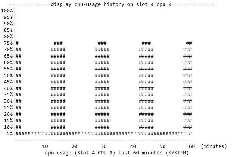
Symptom
The CPU usage of the active MPU on multiple devices periodically rose to about 75%, as shown in the following figure:
Troubleshooting procedure
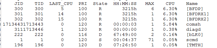
1. When the CPU usage increases, the process statistics show that the comsh process occupies a high CPU usage.
<Sysname>monitor thread dumbtty slot 4 cpu 0
2. View log files. The information shows that many SSH users continuously log in periodically.
Root cause
An abnormal server attempts periodic logins to the device and executes a series of commands within a short period. When users repeatedly log in and out of the device and execute display commands in a short period, many temporary processes will be created, resulting in a sudden increase in CPU usage.
Solution
To resolve server login anomaly, the device performs CPU optimization based on SSH exceptions to prevent a sudden increase in CPU usage.
Abnormal route learning between IPv6 IS-IS neighbors
Symptom
A non-H3C device and an H3C CR16000-F router cannot establish an IPv6 IS-IS neighbor relationship correctly.
· If the network type is P2P, the two devices cannot establish an IPv6 IS-IS neighbor relationship.
· If the network type is broadcast, the two devices establish an IPv6 IS-IS neighbor relationship successfully, but they cannot learn IS-IS routes from each other correctly.
Troubleshooting procedure
1. Check the logs on the CR16000-F router for error messages.
When IS-IS configuration is completed on both the non-H3C device and the CR16000-F router, the following IS-IS error message occurs:
ISIS-1-ADJ: No common mt id with circuit(Ten-GigabitEthernet3/1/1). IIH ignored.
According to the message, IIH message verification failed because XGE3/1/1 and an IS-IS neighbor have different topology IDs (MTID). XGE3/1/1 is the interface connecting the CR16000-F router to the non-H3C device. Therefore, this issue is the reason why the two devices failed to establish an IPv6 IS-IS neighbor relationship.
The requirements for establishing an IPv6 IS-IS adjacency vary by network type as follows:
¡ When the network type is P2P, the interconnect interfaces on the two devices must share a minimum of one topology ID.
¡ When the network type is broadcast, the two devices can establish an IS-IS adjacency regardless of whether they have the same topology ID as long as they are in the same LAN. In broadcast mode, topology ID information is advertised in LSPs. If the two devices use different topology IDs, they will fail to learn routes from each other, because LSP verification will fail due to topology ID difference.
2. View IS-IS packet statistics.
According the output of the display isis packet hello by-interface verbose command, the No common MT ID (P2P) field has statistics. After repeating this command, you can find that the value for this field keeps increasing. It is suggested that the two devices do not use the same topology ID for IPv6 IS-IS neighbor relationship establishment.
<Sysname> display isis packet hello by-interface verbose
Hello packet information for IS-IS(1)
-------------------------------------
Interface: Ten-GigabitEthernet3/1/1
Total output packets : 235 Total output error packets : 0
Total input packets : 234 Total input error packets : 0
Input packets with errors
Bad packet length : 0 Bad header length : 0
Jumbo packet : 0 Bad protocol description : 0
Bad protocol ID : 0 Bad protocol version : 0
Unknown packet type : 0 Bad max area count : 0
Bad system ID length : 0 Bad circuit type : 0
Bad auth TLV : 0 Bad area address TLV : 0
Auth failure : 0 Excessive area addresses : 0
Bad NBR TLV : 0 Excessive auth TLVs : 0
Excessive IF Addr TLVs : 0 Excessive IF addresses : 0
Bad IF address TLV : 0 Duplicate system ID : 0
Bad TLV length : 0 Bad IP address : 0
Duplicate IP address : 0 Mismatched area address : 0
Mismatched protocol : 0 Mismatched network type : 0
Bad IPv6 address TLV : 0 Bad IPv6 address : 0
Duplicate IPv6 address : 0 Bad MT ID TLV : 0
SNPA conflict (LAN) : 0 Excessive NBR SNPAs (LAN) : 0
Mismatched level (LAN) : 0 Bad 3-Way option TLV (P2P) : 0
No common MT ID (P2P) : 32 Bad circuit ID (P2P) : 0
3. Collect the configuration files of the two devices and compare them.
Part of the ISIS configuration for the non-H3C device is as follows:
#
isis 1
is-level level-2
cost-style wide
#
ipv6 enable topology ipv6
#
topology v4 topology-id 10
#
ipv6 topology v6 topology-id 20
#
interface Ten-GigabitEthernet3/1/1
undo shutdown
ipv6 enable
ipv6 address X:X:X:X/120
isis ipv6 enable 1
isis circuit-type p2p
isis circuit-level level-2
#
The counterpart on the CR16000-F router is as follows:
#
isis 1
is-level level-2
cost-style wide
……
#
address-family ipv6 unicast
#
interface Ten-GigabitEthernet3/1/1
port link-mode route
isis ipv6 enable 1
isis circuit-level level-2
isis circuit-type p2p
ipv6 address Y:Y:Y:Y/120
#
According to the above comparison result, the non-H3C device is enabled with the IPv6 IS-IS multi-topology feature (also called IPv6 IS-IS MTR). By default, this feature is disabled on H3C devices, which causes the neighbor relationship establishment failure.
Root cause
The enabling status of the IPv6 IS-IS multi-topology feature on the non-H3C device is different from that on the H3C device, because the multi-topology command is not configured on the H3C device by default.
Solution
On the CR16000-F router, execute the multi-topology command to enable the IPv6 IS-IS multi-topology feature in IS-IS IPv6 address family view. This feature enables separate route calculation in IPv4 and IPv6 topologies.
Failure to issue OSPF default routes
Symptom
Routers A and Router B establish an OSPF neighbor relationship. After you execute the default-route-advertise command on Router A to redistribute a default route into the OSPF routing domain, Router B cannot learn the default route advertised by Router A.
Troubleshooting procedure
1. Execute the display ospf peer command to verify that the OSPF neighbor relationship between two devices is established correctly.
<RouterA> display ospf peer
OSPF Process 1 with Router ID 2.2.2.1
Neighbor Brief Information
Area: 0.0.0.0
Router ID Address Pri Dead-Time State Interface
3.3.3.1 1.1.1.2 1 33 Full/ - XGE3/1/1
<RouterB> display ospf peer
OSPF Process 1 with Router ID 3.3.3.1
Neighbor Brief Information
Area: 0.0.0.0
Router ID Address Pri Dead-Time State Interface
2.2.2.1 1.1.1.1 1 36 Full/ - XGE3/1/1
2. Verify that both ends are configured with the default-route-advertise command.
Execute the display current-configuration configuration ospf command to verify that both devices are configured with the default-route-advertise command and have no route filtering configuration.
<RouterA> display current-configuration configuration ospf
#
ospf 1
default-route-advertise type 2
area 0.0.0.0
network 1.1.1.0 0.0.0.255
<RouterB> display current-configuration configuration ospf
#
ospf 1
default-route-advertise
area 0.0.0.0
network 1.1.1.0 0.0.0.255
3. Execute the display ip routing-table command to view the routing tables on both devices and verify that the route learning results are correct.
Router A has a default static route with a preference of 60 in its routing table.
<RouterA> display ip routing-table
Destinations : 17 Routes : 17
Destination/Mask Proto Pre Cost NextHop Interface
0.0.0.0/0 Static 60 0 2.2.2.2 XGE3/1/1
0.0.0.0/32 Direct 0 0 127.0.0.1 InLoop0
1.1.1.0/24 Direct 0 0 1.1.1.1 XGE3/1/1
1.1.1.0/32 Direct 0 0 1.1.1.1 XGE3/1/1
1.1.1.1/32 Direct 0 0 127.0.0.1 InLoop0
Router A has a default static route with a preference of 200 in its routing table, but does not have the default route with a preference of 150 advertised by OSPF.
<RouterB> display ip routing-table
Destinations : 17 Routes : 17
Destination/Mask Proto Pre Cost NextHop Interface
0.0.0.0/0 Static 200 0 3.3.3.2 XGE3/1/1
0.0.0.0/32 Direct 0 0 127.0.0.1 InLoop0
1.1.1.0/24 Direct 0 0 1.1.1.2 XGE3/1/1
1.1.1.0/32 Direct 0 0 1.1.1.2 XGE3/1/1
4. Execute the display ospf lsdb command to view OSPF LSDB information on Router B and verify that Router A has advertised the route.
The output shows that Router B has two default route entries: one generated by itself (3.3.3.1) and one advertised by Router A (2.2.2.1). This confirms that Router A has advertised a default route to Router B.
<RouterB> display ospf lsdb
OSPF Process 1 with Router ID 3.3.3.1
Link State Database
Area: 0.0.0.0
Type LinkState ID AdvRouter Age Len Sequence Metric
Router 3.3.3.1 3.3.3.1 361 48 80000006 0
Router 2.2.2.1 2.2.2.1 362 48 80000006 0
AS External Database
Type LinkState ID AdvRouter Age Len Sequence Metric
External 0.0.0.0 3.3.3.1 361 36 80000001 1
External 0.0.0.0 2.2.2.1 1444 36 80000003 1
Root cause
According to the protocol standard, when a router generates and advertises a Type-5 LSA that describes a default route, by default, the router does not calculate default routes received from other routers.
In this case, Router B has a locally configured static default route and is configured to redistribute a default route to the OSPF routing domain. Router B generates a Type-5 LSA that describes the default route. Therefore, when Router B receives a default route LSA from Router A, it does not replace the locally generated default route, even if the new default route has a preference of 150, which is higher than the preference of 200 for the local one.
Solution
In OSPF view on Router B, execute the default-route-advertise command with the permit-calculate-other keyword specified. The router will continue to calculate default routes received from other routers after generating and advertising a Type-5 LSA that describes a default route.
Route flapping caused by attribute changes of BGP summary routes
Symptom
As shown in Figure 4, Router D establishes an EBGP peer relationship with Router A, Router B, and Router C separately. Router D learns route 1.1.1.1/32 from Router A and route 1.1.1.2/32 from Router B. Router D summarize the two routes as route 1.1.1.0/24 before transmitting them to Router C. Route 1.1.1.1/32 is a local network route advertised by BGP on Router A after the configuration of the network command. Route 1.1.1.2/32 is a static route redistributed by Router B after the configuration of the import-route command. BGP route dampening is enabled on Router C by using the dampening command. When route 1.1.1.2/32 flaps on Router B, summary route 1.1.1.0/24 should remain stable on Router D. However, the summary route also flaps in fact.
Troubleshooting procedure
|
|
NOTE: The following information is for illustration only. |
1. Use the display bgp routing-table ipv4 unicast command to view the BGP routes learned by Router D.
a. View route 1.1.1.1/32 learned from Router A.
<RouterD> display bgp routing-table ipv4 1.1.1.1 32
BGP local router ID: 20.0.0.2
Local AS number: 200
Paths: 1 available, 1 best
BGP routing table information of 1.1.1.1/32:
From : 10.0.0.1 (1.1.1.1)
Rely nexthop : 10.0.0.1
Original nexthop: 10.0.0.1
OutLabel : NULL
RxPathID : 0x0
TxPathID : 0x0
AS-path : 100
Origin : igp
Attribute value : MED 0, pref-val 0
State : suppressed, valid, external, best
IP precedence : N/A
QoS local ID : N/A
Traffic index : N/A
b. View route 1.1.1.2/32 learned from Router B.
<RouterD> display bgp routing-table ipv4 1.1.1.2 32
BGP local router ID: 20.0.0.2
Local AS number: 200
Paths: 1 available, 1 best
BGP routing table information of 1.1.1.2/32:
From : 20.0.0.1 (20.0.0.1)
Rely nexthop : 20.0.0.1
Original nexthop: 20.0.0.1
OutLabel : NULL
RxPathID : 0x0
TxPathID : 0x0
AS-path : 100
Origin : incomplete
Attribute value : MED 0, pref-val 0
State : suppressed, valid, external, best
IP precedence : N/A
QoS local ID : N/A
Traffic index : N/A
Router D can learn two detailed routes, one from Router A and the other from Router B. The two routes have different ORIGIN attributes.
¡ igp—Originated in the AS. The origin of routes advertised with the network command is IGP.
¡ egp—Learned through an exterior gateway protocol (EGP).
¡ incomplete—Unknown origin. The origin of routes redistributed from IGP protocols is INCOMPLETE.
Route 1.1.1.1/32 is a local network route advertised by BGP on Router A after the configuration of the network command. The ORIGIN attribute of route 1.1.1.1/32 is igp. Route 1.1.1.2/32 is a static route redistributed by using the import-route command. The ORIGIN attribute of route 1.1.1.2/32 is incomplete.
2. Use the display bgp routing-table ipv4 unicast command to view the BGP summary routes on Router D before route flapping.
<RouterD> display bgp routing-table ipv4 1.1.1.0
BGP local router ID: 20.0.0.2
Local AS number: 200
Paths: 1 available, 1 best
BGP routing table information of 1.1.1.0/24:
Original nexthop: 127.0.0.1
OutLabel : NULL
RxPathID : 0x0
TxPathID : 0x0
AS-path : (null)
Origin : incomplete
Attribute value : pref-val 32768
State : valid, local, best
This route is an atomic-aggregated route
Aggregator : AS 200, Aggregator ID: 20.0.0.2
IP precedence : N/A
QoS local ID : N/A
Traffic index : N/A
When the summarized routes have different ORIGIN attributes, the ORIGIN attribute of the summary route is selected in descending order of Incomplete > EGP > IGP. In this example, the ORIGIN attribute of route 1.1.1.1/32 is IGP and the ORIGIN attribute of route 1.1.1.2/32 is Incomplete. Therefore, the ORIGIN attribute of summary route 1.1.1.0/24 is Incomplete.
3. Use the display bgp routing-table ipv4 unicast command to view the BGP summary routes on Router D after route flapping.
<RouterD> display bgp routing-table ipv4 1.1.1.0
BGP local router ID: 20.0.0.2
Local AS number: 200
Paths: 1 available, 1 best
BGP routing table information of 1.1.1.0/24:
Original nexthop: 127.0.0.1
OutLabel : NULL
RxPathID : 0x0
TxPathID : 0x0
AS-path : (null)
Origin : igp
Attribute value : pref-val 32768
State : valid, local, best
This route is an atomic-aggregated route
Aggregator : AS 200, Aggregator ID: 20.0.0.2
IP precedence : N/A
QoS local ID : N/A
Traffic index : N/A
Host route 1.1.1.2/32 on Router B flaps and is withdrawn. In this situation, the summary route only has one summarized route, route 1.1.1.1/32. Since the ORIGIN attribute of route 1.1.1.1/32 is IGP, the ORIGIN attribute of the summary route changes to IGP. After route 1.1.1.2/32 is re-added, the ORIGIN attribute of the summary route restores to Incomplete. In conclusion, the cause for this issue is that the flapping of route 1.1.1.2/32 causes the ORIGIN attribute of the summary route to change. Repeated ORIGIN attribute changes trigger route suppression by Router C, which is enabled with BGP route dampening by the dampening command.
4. Fix the ORIGIN attribute of summary route 1.1.1.0/24 at IGP.
a. Create routing policy policy1 with a node number of 10. Set the match mode to permit and configure the routing policy to set the ORIGIN attribute of matching BGP routes to IGP.
<RouterD> system-view
[RouterD] route-policy policy1 permit node 10
[RouterD-route-policy-policy1-10] apply origin igp
b. In BGP IPv4 unicast address family view, add summary route 1.1.1.0/24 to the BGP routing table and apply routing policy policy1 to that route.
<RouterD> system-view
[RouterD] bgp 200
[RouterD-bgp-default] address-family ipv4 unicast
[RouterD-bgp-default-ipv4] aggregate 1.1.1.0 255.255.255.0 attribute-policy policy1
Root cause
Flapping of a summarized route causes changes in the ORIGIN attribute of the summary route, which triggers route suppression.
Solution
Use a routing policy to fix the ORIGIN attribute of the summary route.
Tracert responses show unexpected addresses in a VPN network
Symptom
As shown in Figure 5, the device is deployed in a VPN network as a PE (PE 1 and PE 2). When the tracert command is used to display the VPN traffic path between CE 1 and CE 2, the command output shows addresses not on the path, but traffic forwarding remains normal.
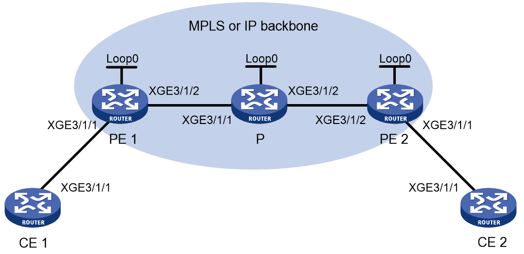
|
Device |
Interface |
IP Address |
Device |
Interface |
IP Address |
|
CE 1 |
XGE3/1/1 |
30.0.0.2/24 |
P |
Loop0 |
N/A |
|
On PE 1 |
Loop0 |
8.8.8.8/32 |
|
XGE3/1/1 |
N/A |
|
|
XGE3/1/1 |
30.0.0.1/24 |
|
XGE3/1/2 |
N/A |
|
|
XGE3/1/2 |
N/A |
On PE 2 |
Loop0 |
N/A |
|
CE 2 |
XGE3/1/1 |
20.0.0.2/24 |
|
XGE3/1/1 |
20.0.0.1/24 |
|
|
|
|
|
XGE3/1/2 |
N/A |
Troubleshooting procedure
|
|
NOTE: The following output information is for illustration only, and it might vary by software or hardware of the device. |
1. Use the tracert command on both CE 1 and CE 2 to check if the echo addresses on the service paths are displayed correctly.
# Run a tracert from CE 1 to CE 2.
[CE1] tracert 20.0.0.2
traceroute to 20.0.0.2 (30.0.0.2), 30 hops at most, 40 bytes each packet, press CTRL+C to break
1 30.0.0.1 (30.0.0.1) 1.000 ms 0.000 ms 1.000 ms
……
11 20.0.0.1 (20.0.0.1) [AS 65002] 1.000 ms 1.000 ms 1.000 ms
12 20.0.0.2 (20.0.0.2) [AS 65002] 2.000 ms 2.000 ms 2.000 ms
The echo addresses are displayed correctly. The first hop is a direct address, and the 11th hop is the direct address of CE 2.
Run a tracert from CE 2 to CE 1.
[CE2] tracert 30.0.0.2
traceroute to 30.0.0.2 (30.0.0.2), 30 hops at most, 40 bytes each packet, press CTRL+C to break
1 20.0.0.1 (20.0.0.1) 0.000 ms 1.000 ms 0.000 ms
……
11 8.8.8.8 (8.8.8.8) 2.000 ms 1.000 ms 2.000 ms
12 30.0.0.2 (30.0.0.2) [AS 65001] 2.000 ms 1.000 ms 3.000 ms
The echo addresses are displayed abnormally. Under normal circumstances, the 11th hop should display the direct address of CE 2, but the actual address shown is 8.8.8.8.
Normal service forwarding and normal final hop for tracert indicate that the routing and interfaces are free of anomalies.
2. Use the display ip interface brief command on PE 1 to check if address 8.8.8.8 exists.
[PE1] display ip interface brief
*down: administratively down
(s): spoofing (l): loopback
Interface Physical Protocol IP address/Mask VPN instance Description
XGE3/1/1 up up 30.0.0.1/24 v1 --
XGE3/1/2 up up 1.1.1.2/8 -- --
Loop1 up up(s) 2.2.2.2/32 -- --
Loop0 up up(s) 8.8.8.8/32 v1 --
The interface with address 8.8.8.8 has also been bound to a VPN.
3. Use packet capture software to capture packets and check if the device's tracert echo address is correct.
![]()
The device's echo address is 8.8.8.8.
Root cause
This symptom is a normal part of the device's packet processing. In a VPN network, if the device is not directly connected to the next hop when processing tracert messages, it will use the smallest IP address from all interfaces bound to the VPN service as the source IP to transmit ICMP messages. This can result in tracert echo information that does not match expectations.
Traffic not routed through a VPN does not have this issue.
Solution
This issue is a normal part of the device's packet processing and merely reflects a variation in tracert responses. It does not affect packet forwarding.
Traffic not load-balanced among member ports of a Layer 3 aggregate interface used as the ECMP route output interface
Symptom
The device has two equal-cost static routes to the destination. The output interfaces of the static routes are Layer 3 aggregate interfaces Route-Aggregation1 and Route-Aggregation2. Each Layer 3 aggregate interface has two member ports. Traffic is not load-balanced among the two member ports. For example, the traffic load on one 100GE member port is 70% of the total interface bandwidth, and traffic load on the other 100GE member port is empty.
Troubleshooting procedure
|
|
NOTE: The following output information is for illustration only. The output information might vary by device model. |
1. Use the display link-aggregation verbose command to display detailed information about the aggregation groups that correspond to the specified aggregate interfaces. The output shows that the two member ports are both in Selected state.
<Sysname> display link-aggregation verbose
Loadsharing Type: Shar -- Loadsharing, NonS -- Non-Loadsharing
Port Status: S -- Selected, U -- Unselected, I -- Individual
Port: A -- Auto
Flags: A -- LACP_Activity, B -- LACP_Timeout, C -- Aggregation,
D -- Synchronization, E -- Collecting, F -- Distributing,
G -- Defaulted, H -- Expired
Aggregate Interface: Route-Aggregation1
Aggregation Mode: Static
Loadsharing Type: Shar
Port Status Priority Oper-Key Role
HGE3/1/1 S 32768 8 None
HGE3/1/2 S 32768 8 None
Aggregate Interface: Route-Aggregation2
Aggregation Mode: Static
Loadsharing Type: Shar
Port Status Priority Oper-Key Role
HGE3/1/1 S 32768 8 None
HGE3/1/2 S 32768 8 None
2. Upon receiving traffic, the device searches the routing table and obtains two matching ECMP routes.
a. The device then performs the first hash calculation for route selection to forward matching traffic out of the specified Layer 3 aggregate interface. In the route selection process, the device calculates a hash value based on the packet characteristics such as 5-tuple. Then, it performs a modulo operation on this hash value with 2 (the number of ECMP routes). The selected ECMP route varies by modulo result.
b. Assume the traffic hashes to ECMP route 1 with Layer 3 aggregate interface Route-Aggregation1 as the output interface. When forwarding traffic through Route-Aggregation1, the device performs the second hash calculation for route selection to forward the traffic out of the specified member port of Route-Aggregation1. The route selection process is similar to the first hash calculation process. The device calculates a hash value based on the packet characteristics. Then, it performs a modulo operation on this hash value with 2 (the number of aggregation group members). The selected member port varies by modulo result.
In the first hash calculation for selecting a Layer 3 aggregate interface, the traffic is already filtered. For traffic reaching Route-Aggregation1, the second hash calculation generates basically the same result as the first hash calculation. The traffic is forwarded through a specific member port on the Layer 3 aggregate interface. As a result, traffic is not load-balanced across the member ports.
According to the analysis, if the number of ECMP routes is the same as or a multiple of the number of member ports in the aggregation group, traffic might not be load-balanced across the member ports.
Root cause
The ECMP route and link aggregation hash parameters are the same. In addition, the number of ECMP routes is the same as or a multiple of the number of member ports in the aggregation group. As a result, traffic is not load-balanced across the member ports.
Solution
· To avoid uneven traffic load on aggregation member ports, you can use the link-aggregation global load-sharing mode or ip load-sharing mode command to adjust the load sharing mode for generating different results in the two hash calculations. For more information about the link-aggregation global load-sharing mode or ip load-sharing mode commands, see Ethernet link aggregation or IP forwarding basics commands in H3C CR16000-F Routers Command Reference.
· You can also make adjustments to have the number of ECMP routes different from the number of aggregation member ports, or to avoid the number of ECMP routes to be a multiple of the number of aggregation member ports. For example, you can change the number of ECMP routes to 2 and the number of member ports in the aggregation group to 3.
Device as the SSH client unable to log in to the SSH server
Symptom
After you enter the username on the device as the SSH client to log in to the SSH server, the system gets stuck in the connecting status and you cannot continue to enter the password, causing SSH login failure.
Troubleshooting procedure
|
|
NOTE: The following output is only an example and does not reflect the actual software or hardware information of the device. |
1. Check the connectivity between the device and the SSH server.
Execute the ping command to identify whether the device can reach the SSH server at 12.1.1.1. If the ping result shows no packet loss, the device can reach the SSH server correctly.
[Sysname] ping -a 12.1.1.2 12.1.1.1
Ping 12.1.1.1 (12.1.1.1) from 12.1.1.2: 56 data bytes, press CTRL+C to break
56 bytes from 12.1.1.1: icmp_seq=0 ttl=255 time=0.772 ms
56 bytes from 12.1.1.1: icmp_seq=1 ttl=255 time=0.627 ms
56 bytes from 12.1.1.1: icmp_seq=2 ttl=255 time=0.587 ms
56 bytes from 12.1.1.1: icmp_seq=3 ttl=255 time=0.605 ms
56 bytes from 12.1.1.1: icmp_seq=4 ttl=255 time=0.714 ms
--- Ping statistics for 12.1.1.1 ---
5 packet(s) transmitted, 5 packet(s) received, 0.0% packet loss
round-trip min/avg/max/std-dev = 0.587/0.661/0.772/0.071 ms
2. Identify whether the SSH service on the SSH server is normal.
Configure another device as an SSH client. If the SSH client can log in to the SSH server successfully, the SSH service is normal.
3. Identify whether the SSH server restricts logins from the SSH client.
Execute the display current-configuration command to view the SSH server configuration. The output shows an ACL is used for access control for the SSH client.
[Sysname]display current-configuration
ssh server acl 2010
#
acl basic 2010
description Manager_IP
rule 5 permit
#
4. Identify whether the packet interaction between the SSH client and the SSH server is normal.
Send an SSH connection request from the SSH client and execute the display tcp command to view breif TCP connection information. The output shows that no TCP connection information exists between the SSH client and the SSH server.
[Sysname] display tcp
*: TCP connection with authentication
Local Addr:port Foreign Addr:port State Slot PCB
0.0.0.0:0 0.0.0.0:0 CLOSED 0 0x000000000002b895
0.0.0.0:0 0.0.0.0:0 CLOSED 0 0x000000000002b892
0.0.0.0:0 0.0.0.0:0 CLOSED 0 0x000000000002b88c
0.0.0.0:21 0.0.0.0:0 LISTEN 0 0xffffffffffffffbe
0.0.0.0:22 0.0.0.0:0 LISTEN 0 0xffffffffffffffbd
0.0.0.0:23 0.0.0.0:0 LISTEN 0 0xffffffffffffff9d
0.0.0.0:179 111.1.1.1:0 LISTEN 0 0xffffffffffffffa2
0.0.0.0:179 120.1.1.1:0 LISTEN 0 0xffffffffffffffb0
0.0.0.0:179 123.1.1.1:0 LISTEN 0 0xffffffffffffffa4
0.0.0.0:179 133.1.1.1:0 LISTEN 0 0xffffffffffffffa8
0.0.0.0:11111 0.0.0.0:0 LISTEN 1 0xffffffffffffff9d
0.0.0.0:11111 0.0.0.0:0 LISTEN 2 0xffffffffffffff9d
5. Identify whether TCP-related settings affect TCP connection setup.
Execute the display current-configuration command to view the device configuration. The output shows that the attack prevention feature is configured, which enables the device to drop TCP messages over SSH from the peer. The SSH connection failed to be set up.
[Sysname]display current-configuration
#
tcp syn-COOKIE enable
tcp anti-naptha enable
tcp anti-syn-flood flow-based enable
tcp anti-syn-flood interface-based enable
#
Root cause
The on-site detection shows that attack prevention on the device as the SSH client and the SSH server is not consistent. As a result, the device cannot log in to the SSH server through SSH connection.
Solution
Execute the undo tcp anti-syn-flood flow-based enable command to disable flow-based TCP SYN flood attack prevention. Then, the device as the SSH client can log in to the SSH server when you enter the username and password correctly.