- Table of Contents
- Related Documents
-
| Title | Size | Download |
|---|---|---|
| 01-Text | 1.33 MB |
Software package naming conventions
Features provided by the vSCN network elements
Obtaining the vSCN software package
Installing the server in the target location
Installing H3Linux on the server
Logging in to the HDM of UniServer R4900 G3
Editing the power configuration for UniServer R4900 G3
Logging in to the remote console of UniServer R4900 G3
Installing H3Linux on the server
Logging in to H3Linux for the first time
Configuring the server's clock
Configuring an IP address for a network interface on the server
Uploading vSCN image files and the toolkit
Uploading the software package
Adding execute permissions to the script files in the package
Planning service network interfaces
Configure the network interfaces associated with the N2, N3, N6 interfaces
Planning the topology and connect cables
Creating the container for the vSCN and running the vSCN
Logging in to the CLI of the vSCN
Configuring the vSCN at the CLI
Network elements installed by default
Logging in to the Web interface
Logging in to the Web interface for the first time
Logging out of the Web interface
Product overview
About the vSCN5100
H3C vSCN5100 is a core network product based on H3C's proprietary network function virtualization (NFV) architecture, aimed at the enterprise market. It addresses the requirement for large-scale 5G mobile communication deployments in industries such as rail transport, electric power, and campuses. The vSCN5100 runs on x86 architecture servers, such as the H3C UniServer R4900 G3, and is deployed as a container. It offers a large user capacity, high availability, high throughput, and a rich set of service features. Together with H3C's mobile communication base stations and endpoints, the vSCN5100 can provide a complete 5G network solution. Unless otherwise specified, H3C vSCN5100 is referred to as vSCN in this document.
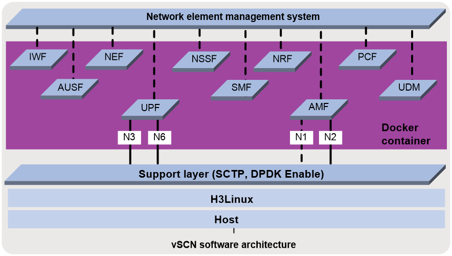
vSCN software architecture
The vSCN runs in a Docker container on H3Linux. The installation and maintenance engineers must have a basic knowledge of Linux.
Figure 1 shows the software architecture for deploying the vSCN based on Docker containers.
· The host is the underlying device that runs the vSCN, such as H3C UniServer R4900 G3.
· H3Linux is the operating system running on the underlying host.
· The Docker container is the container where the vSCN network element nodes are located.
· The support layer provides Stream Control Transmission Protocol (SCTP) coupling and packet forwarding in DPDK mode for each network element node in the vSCN.
· AMF, SMF, and UPF are vSCN network element nodes.
Figure 1 Software architecture
vSCN software page
Software package type
The vSCN runs in a Docker container based on the H3Linux operating system. To support the installation and operation of the vSCN, H3C provides a software package compatible with the software version of the product. The software package contains the operating system installation package, vSCN installation package, and tool package.
· H3Linux operating system image
The H3Linux operating system image is an H3Linux system image file in .iso format. Install H3Linux on the host before you install the vSCN package.
The vSCN installation package is in .tar.gz format.
This package contains script files for installing, upgrading, or maintaining the vSCN.
Software package naming conventions
H3C provides the operating system installation package, core network installation package, and toolkit when it releases a software version.
· The operating system installation package is named using the H3Linux-H3Linux version number-vSCN format, for example, H3Linux-V202-vSCN.iso.
· The core network package is named using the vSCN5100-CMW910-version number format, for example, vSCN5100-CMW910-A5118.tar.gz.
· The toolkit is named using the vSCN5100_Tools format, for example, vSCN5100_Tools.tar.
|
|
CAUTION: As a best practice to avoid installation failure, use the vSCN installation package and toolkit with the same software version number when you install the software. |
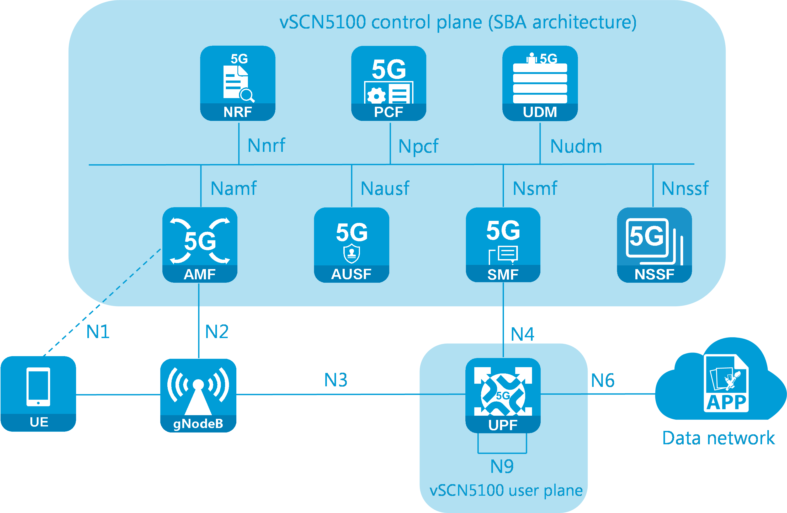
vSCN logical networking
Figure 2 vSCN logical networking
Features provided by the vSCN network elements
As shown in Figure 2, the vSCN contains the following network elements:
· Access and Mobility Management Function (AMF)—Registration management, user authentication, connection management, reachability management, mobility management, and the transmission of SM messages between UE and SMF.
· Session Management Function (SMF)—Session management, address allocation, UPF selection, and configuration of local traffic control rules.
· UDM (Unified Data Management)—3GPP AKA authentication certificate processing, user ID management (such as storing and managing SUPI), resolving encrypted subscription identifiers (SUCI), access authorization based on subscription data, registration management for UE's NF, support of service/session continuity, and transmission of received SMS messages.
· Authentication Server Function (AUSF)—User authentication when accessing the 5G network from both 3GPP and non-3GPP networks. AUSF provides authentication parameters based on service network requests, authenticates the User Equipment (UE), and provides authentication parameters to the AMF after authentication.
· Policy Control Function (PCF)—Provides unified policies for managing network behaviors and provides policies and rules to network entities.
· Unified Data Repository (UDR)—Stores contract data, policy data, and data related to network element functions.
· User Plane Function (UPF)—A user plane network element in the 5G core network. It acts as a connection point between the base station and the Data Network (DN), anchoring User Equipment (UE) mobility within 3GPP Radio Access Technology (RAT) or between different 3GPP RATs. It provides forwarding of data between the UE and DN, packet inspection, and execution of QoS control policies.
· Network Repository Function (NRF)—Provides NF registration, management, and stateful inspection. The 5G core network control plane uses a Service Based Architecture (SBA) design, where network elements provide or use services through the Service Based Interface (SBI). In the 5G core network, elements can obtain their peers' SBI IP addresses via NRF, enabling autodiscovery and connection establishment.
· Network Slice Selection Function (NSSF)—Performs slice selection and management.
|
|
NOTE: NEF, roaming, and lawful interception are not supported in the current software version. |
vSCN interface types
Table 1 vSCN interface types
|
Interface name |
Connected NE |
Features |
Protocol |
|
N1 |
UE and AMF |
Transmits NAS signals. |
NAS |
|
N2 |
RAN and AMF |
Transmits session management and mobility management information (signaling or control plane information). |
NGAP |
|
N3 |
RAN and UPF |
Establishes a tunnel between the UPF and the (R)AN device to transmit user plane data. |
GTP-U |
|
N4 |
SMF and UPF |
The SMF controls the UPF to execute operations related to the user plane session. |
PFCP |
|
N6 |
UPF and DN |
Transmits user plane data. |
IP, DHCP, RADIUS, IPsec, L2TP, and GRE |
|
N8 |
AMF and UDM |
Transmits contract data related to user access and mobility management. |
HTTP/2 |
|
N9 |
UPF and UPF |
Transfers user plane data between UPFs. |
GTP-U |
|
N10 |
SMF and UDM |
Transmits contract data related to user session management. |
HTTP/2 |
|
N11 |
SMF and AMF |
Transmits user session management data. |
HTTP/2 |
|
N12 |
AUSF and AMF |
Transmits authentication data. |
HTTP/2 |
|
N35 |
UDM and UDR |
A UDM accesses data stored in a UDR. |
HTTP/2 |
Preparing for installation
Flow chart
Figure 3 shows the flow chart for installation preparation.
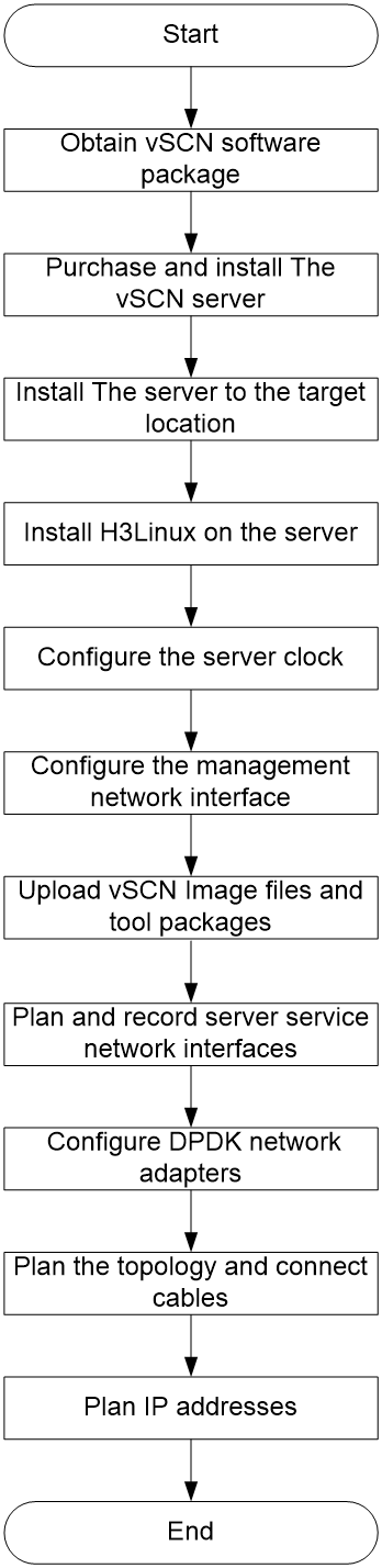
Obtaining the vSCN software package
Before you install the vSCN, you can obtain the vSCN installation package, toolkit, and the specified version of the H3Linux operating system image from Technical Support.
Preparing a vSCN server
The vSCN can only be installed on x86 servers. Table 2 shows the recommended server hardware configuration.
|
|
IMPORTANT: · Unless otherwise specified, this guide uses H3C UniServer R4900 G3 as an example to describe the vSCN installation procedure. · If you use a different server model as a vSCN host, see the user guide provided with that server for installation methods of the hardware and operating system. · During server operation, anomalies such as power outages or hot-swapping disks or network adapters can damage the server hardware or vSCN software. For restrictions and guidelines on how to use a server, see the documentation for that server. |
Table 2 Server hardware configuration requirements
|
Item |
Configuration requirements |
|
Server model |
As a best practice, use an H3C UniServer R4900 G3 or H3C UniServer R4900 G5 server. |
|
CPU |
· Base frequency: ≥ 2.0 GHz · Processor level 2 caching: ≥ 2 MB · Processor count: ≥ 1, with the number of cores on each process greater than 12 |
|
Memory |
≥ 64 GB |
|
Disk |
≥ 100 GB |
|
Network adapter |
≥ 2, one Gigabit network interface and at least one network interface on a physical network adapter model listed in Table 3. The Gigabit network interface manages the server, and the network interface on the physical network adapter sends and receives vSCN control and user plane data. NOTE: · To enhance forwarding efficiency, use the network interfaces on two physical network adapters of the models listed in Table 3 to send and receive data from the vSCN N3 and N6 ports. · For information about how to check the physical network adapter model of a network interface, see "Planning service network interfaces." |
Table 3 Physical network adapter models supported by the vSCN
|
Sequence number |
Physical network adapter model |
Network adapter rate |
|
1 |
82599 |
10G |
|
2 |
I350 |
1G |
|
3 |
XL710 |
40G |
|
4 |
X710 |
10G |
|
5 |
X722 |
1G or 10G |
|
6 |
E810 |
25G or 100G |
|
7 |
BCM57412 |
10G |
Installing the server in the target location
For information about how to install an H3C UniServer R4900 G3 server, see H3C UniServer R4900 G3 Server User Guide.
Installing H3Linux on the server
Multiple methods are available for installing an operating system on the UniServer R4900 G3 server. This document uses HDM as an example. For more information about how to install an operating system on the UniServer R4900 G3 server, see H3C Servers Operating System Installation Guide.
|
|
NOTE: The screenshots in this document are for illustration only and might slightly differ from your HDM webpages. |
Logging in to the HDM of UniServer R4900 G3
About HDM
As shown in Table 4, UniServer R4900 G3 comes with the default HDM login information. You can log in to the HDM of the device by using this default information.
Table 4 Default login information
|
Item |
Default |
|
Dedicated HDM interface IP address. |
192.168.1.2/24 |
|
Username and password |
· Username: admin · Password: Password@_ |
Logging in to the HDM of UniServer R4900 G3
1. Connect the UniServer R4900 G3 dedicated HDM interface to a local PC by using an Ethernet twisted pair.
|
|
CAUTION: As a best practice, directly connect the UniServer R4900 G3's dedicated HDM interface to a local PC by using an Ethernet twisted pair cable and ensure that the PC will not enter sleep mode. If you fail to do so, the installation might fail because network packet loss occurs or the PC enters sleep mode. |
2. Configure an IP address for the local PC.
Change the IP address of the local PC to any IP address within the 192.168.1.0/24 network segment, except for the default IP address for the dedicated HDM interface, such as 192.168.1.1. This can ensure that the local PC is reachable to the UniServer R4900 G3 dedicated HDM interface.
3. Log in to HDM.
The login procedure for logging in to HDM is similar. The following uses IE 11 as an example.
4. Launch Internet Explorer on your PC, enter the dedicated HDM interface's IP address in the browser, and then press Enter. As shown in Figure 4, a security alarm will pop up in the browser.
5. Click Continue to this website (not recommended).
6. Enter your username and password, and then click Login.
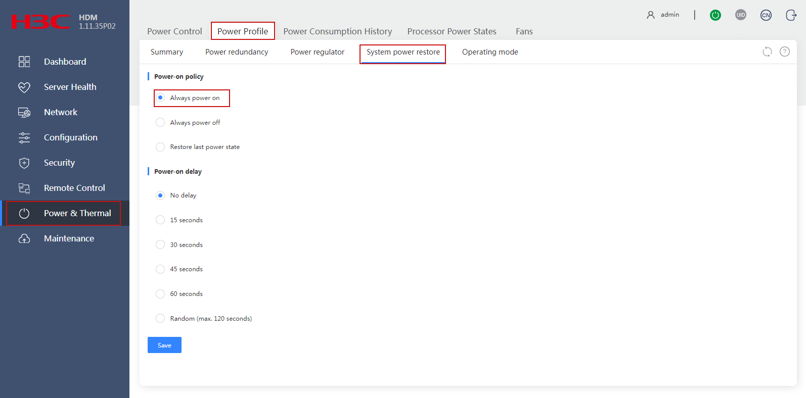
Editing the power configuration for UniServer R4900 G3
To ensure that the UniServer R4900 G3 server can start up automatically after a power cycle, edit the server power settings as follows:
1. As shown in Figure 5, select Power & Thermal from the left navigation pane. Click the Power Profile tab and System power restore tab in sequence.
2. Select Always power on.
3. Click Save.
Figure 5 Editing the power configuration
Logging in to the remote console of UniServer R4900 G3
About remote console
Remote consoles are available in three types: Kernel-based Virtual Machine (KVM), H5 KVM, and Virtual Network Console (VNC). With a remote console, you can perform remote server management and operating system installation.
|
|
IMPORTANT: · Due to the firmware version of H5 KVM, you might experience keyboard input errors (such as lowercase letters displayed as uppercase) or abnormal software uploads. As a best practice, use a non-H5 KVM to access the remote console of UniServer R4900 G3. · In some remote console versions, when you use the Backspace key to delete characters, garbled characters will occur. For these consoles, you can press Ctrl+Backspace or Shift+Backspace to delete characters. For other types of remote consoles, if garbled characters occur, see the console's user guide to resolve the issue. · Unless otherwise specified, this document will use the KVM remote console as an example to describe how to log in to the UniServer R4900 G3 remote console. |
Preparing the login environment for the KVM remote console
Before you use the KVM remote console, prepare the login environment on your local PC. As a best practice, install the Zulu OpenJDK and IcedTea-Web software on your local PC. You can download and install the appropriate software for your platform using the following links. For a Windows system, select the Windows version. For a Linux system, select the Linux version.
· Zulu OpenJDK: https://www.azul.com/downloads/zulu/
· IcedTea-Web: http://icedtea.wildebeest.org/download/icedtea-web-binaries/
As a best practice, use the default settings to install Zulu OpenJDK and IcedTea-Web. For more information about preparing the KVM remote console login environment, see H3C Servers HDM User Guide and the HDM online help.
Logging in to the remote console of UniServer R4900 G3
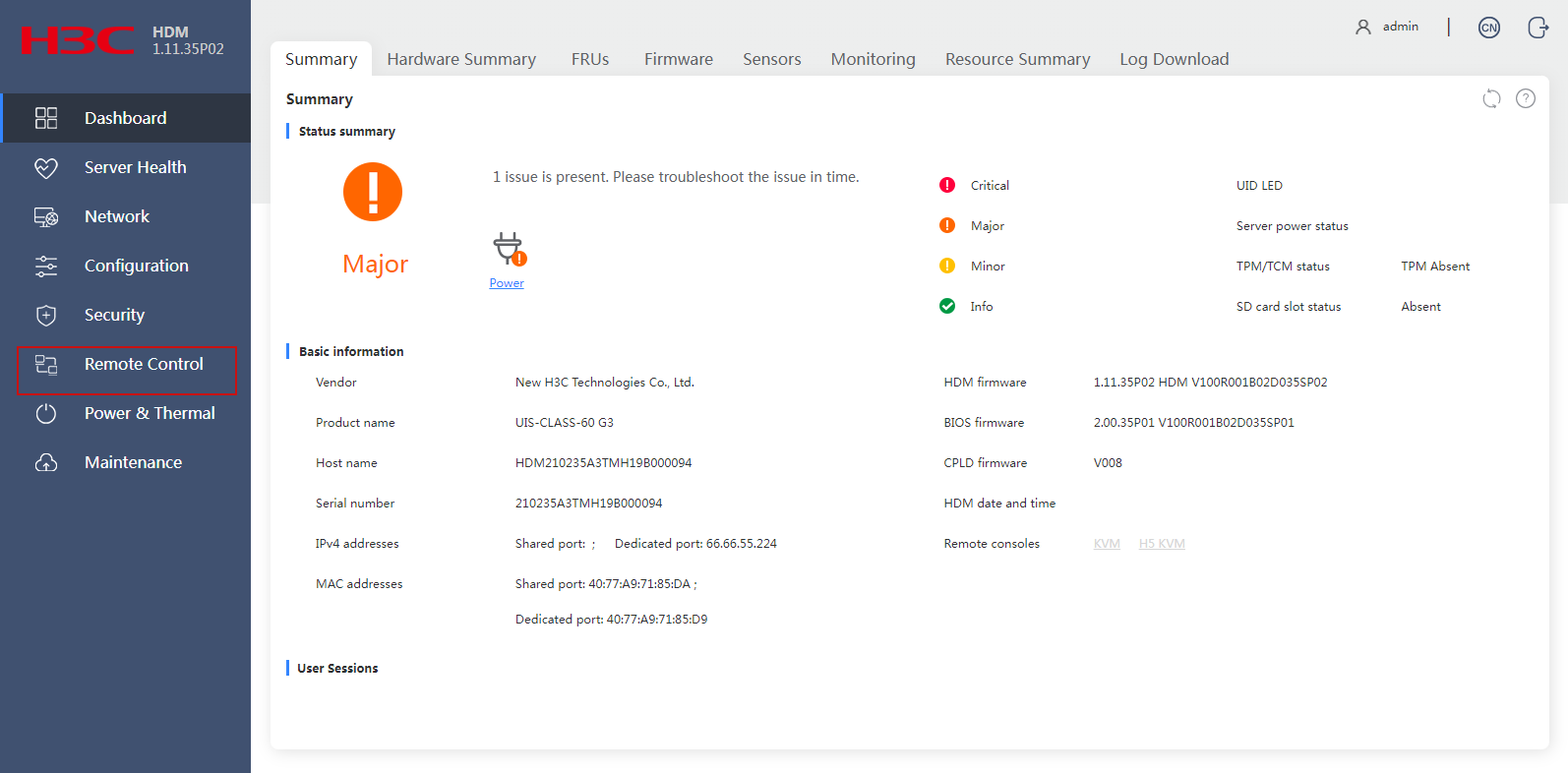
1. Select Remote Control from the left navigation pane.
Figure 6 Accessing the remote control
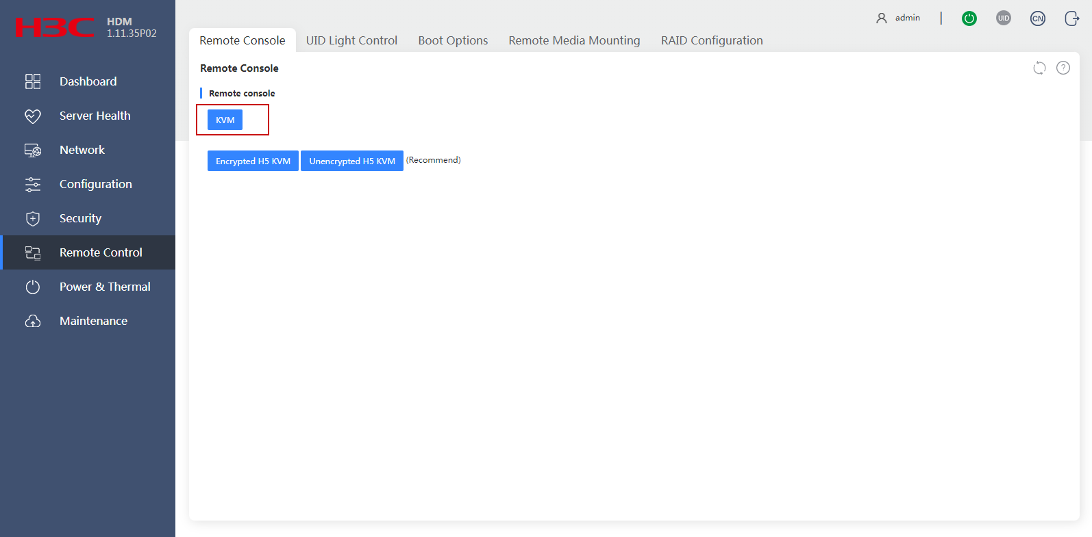
2. On the Remote Console tab, click KVM.
Figure 7 Logging in to the remote console
3. If the Security Warning dialog box appears, click Continue. Then, in the Do you want to run this application? dialog box, select I accept the risk and want to run this application (I), and then click Run to log in to the remote console of UniServer R4900 G3.
Configuring RAID
For data redundancy protection, configure RAID settings in the server's BIOS via the remote console before you install the operating system on UniServer R4900 G3. Depending on the number and size of disks in UniServer R4900 G3, you can select different RAID configurations. For more information about configuring RAID on the UniServer R4900 G3 server, see H3C G3G5 Servers Storage Controller User Guide.
|
|
CAUTION: RAID 0 does not have any fault tolerance mechanism, and it cannot prevent data loss in the event of a disk fault. Do not use RAID 0. As a best practice, use RAID 1 or RAID 5. |
Installing H3Linux on the server
|
|
CAUTION: · During the installation process, record the BIOS boot mode of H3Linux. · For the system to start up successfully, make sure the BIOS boot mode is consistent in installation and startup of H3Linux. For example, if you select UEFI mode when you install H3Linux, you must also boot H3Linux in UEFI mode. For more information about setting the server's BIOS boot mode, see the BIOS user guide or HDM user guide for your server. · If you install the vSCN on a physical server, enable hyperthreading in the BIOS. |
To install H3Linux on the server:
1. Log in to the remote console of the server.
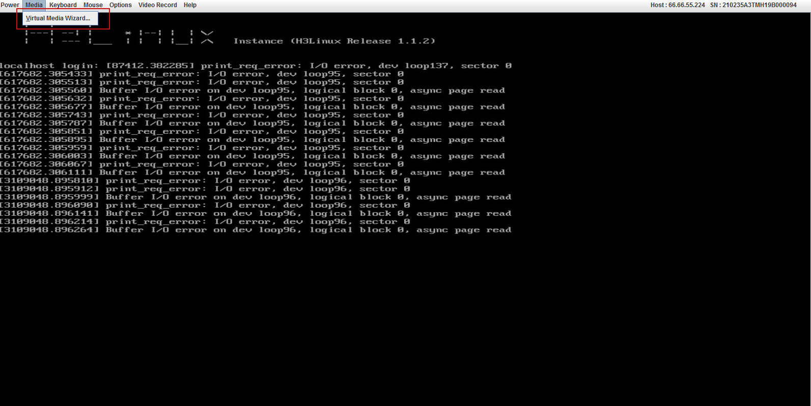
2. Redirect the H3Linux image file to virtual media.
a. Select Media > Virtual Media Wizard in the remote console menu bar.
Figure 8 Opening virtual media
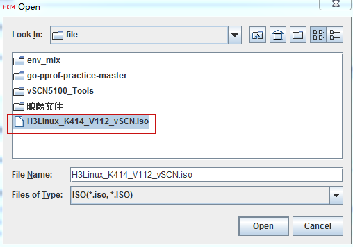
b. Click Browse to select the H3Linux operating system image file from your local PC.
Figure 9 Selecting the H3Linux operating system image

|
|
IMPORTANT: The image file for the H3Linux operating system must be saved in a local PC path that does not contain Chinese characters. |
c. Select the H3Linux operating system image file in the local path and click Open to redirect the H3Linux operating system image file to the virtual media.
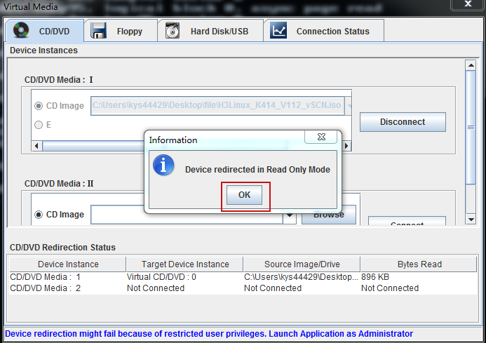
Figure 10 Redirecting the H3Linux image file to virtual media
d. Click OK to complete redirection of the H3Linux operating system image file to the virtual media in read-only mode.
Figure 11 Redirecting the H3Linux image file to virtual media
3. Install H3Linux on the server.
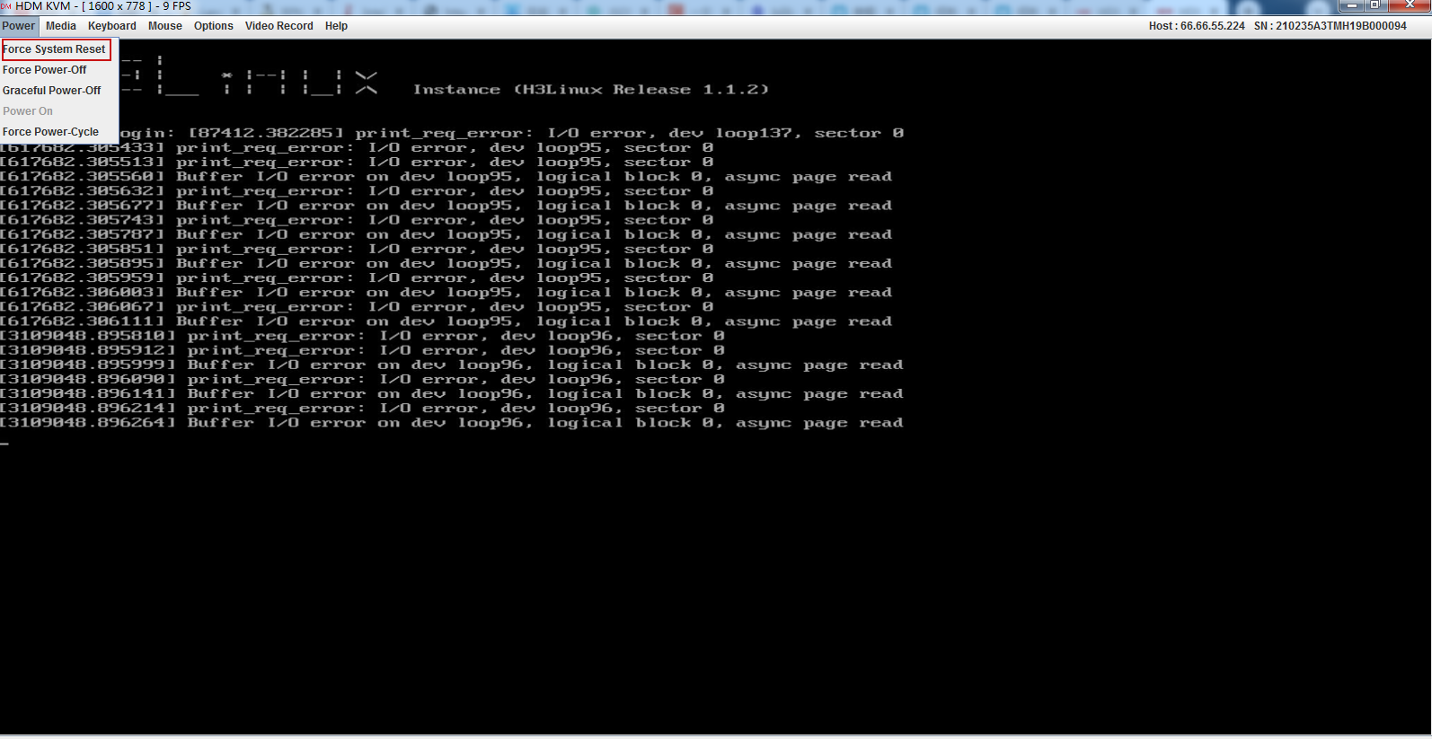
a. Select Power > Force System Reset to boot up the server from the virtual media.
Figure 12 Rebooting UniServer R4900 G3
|
|
NOTE: · When you install H3Linux for the first time, you do not need to configure the server BIOS boot options. · If it is not the first installation, set the server BIOS to boot from the virtual optical drive. For more information about configuring the server BIOS boot options, see H3C Servers Operating System Installation Guide. |
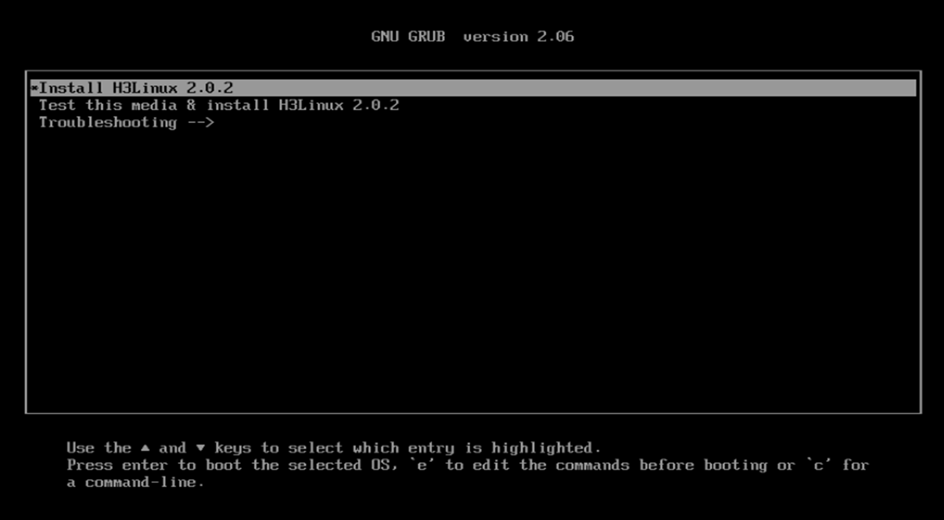
b. Press Enter start H3Linux installation.
|
|
NOTE: · Figure 13 is an installation. The installation process might vary depending on the version of the H3Linux operating system. · H3Linux will be automatically installed on UniServer R4900 G3 without manual intervention. |
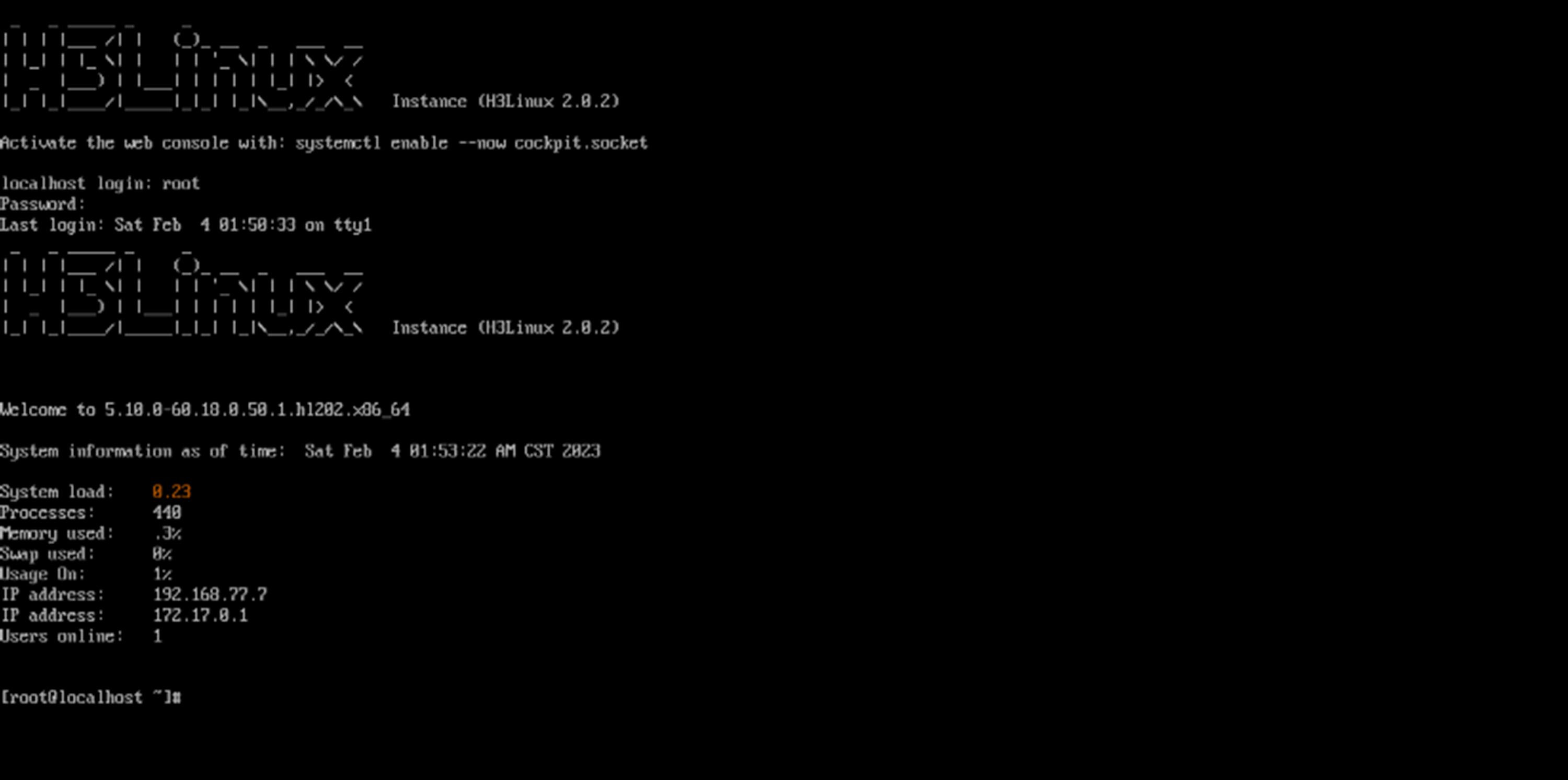
Logging in to H3Linux for the first time
After you install H3Linux, the system will create a root user by default. Use this root user to log in to H3Linux.
Table 5 Default Username and password description
|
User type |
Username |
Password |
|
Root user |
root |
root@vSCN5100 |
|
|
NOTE: · As a best practice to ensure system security, change the default password upon first login to H3Linux. · You can change the password by using the passwd command in H3Linux. For more information about the passwd command, execute the man passwd command in H3Linux. |
Enter the default username and the password, and then press Enter.
Figure 14 Logging in to H3Linux for the first time
Configuring the server's clock
Restrictions and guidelines
You can change the vSCN's system time by using the following methods:
· Change the system time of the Docker container that hosts vSCN.
· Change the system time of the server.
The following uses the second method as an example.
Procedure
1. Log in to H3Linux as a root user via the remote console. Details not shown.
2. Set the time zone.
Set the time zone based on the location of the server.
In this example, the time zone is set to Asia/Shanghai.
[root@localhost ~]# timedatectl set-timezone Asia/Shanghai
3. Use the date -s command to set the system time. For example, set the current time to December 16, 2020, at 20:16:40.
[root@localhost ~]# date -s '2020-12-16 20:16:40'
4. Commit the system time to the device firmware.
[root@localhost ~]# clock –w
|
|
NOTE: · If you do not configure the clock -w command and the server restarts, the server's system time might be reset. · If you have configured the clock -w command and the server restarts, the system time set by the date command is still effective. · As a best practice, execute the reboot command to restart the server and identify whether the system time set by the date command has been committed to the device firmware after you set the system time. |
Configuring an IP address for a network interface on the server
After you configure an IP address for a network interface on the server, you can log in to the server via SSH to manage it. A network interface does not have any requirements on the chip model. The following uses enp61s0f0 as an example.
1. Execute the vim command to open the configuration file for the server's enp61s0f0 network interface.
[root@localhost ~]# vim /etc/sysconfig/network-scripts/ifcfg-enp61s0f0
2. Press Shift+I to enter edit mode, and edit the configuration file as follows:
TYPE=Ethernet
PROXY_METHOD=none
BROWSER_ONLY=no
BOOTPROTO=static
DEFROUTE=yes
IPV4_FAILURE_FATAL=no
IPV6INIT=yes
IPV6_AUTOCONF=yes
IPV6_DEFROUTE=yes
IPV6_FAILURE_FATAL=no
IPV6_ADDR_GEN_MODE=stable-privacy
NAME= enp61s0f0
UUID=f4355dc9-db84-40d4-8e9f-c5814e660d21
DEVICE=enp61s0f0
IPADDR=10.20.1.20
NETMASK=255.255.255.0
GATEWAY=10.20.1.1
ONBOOT=yes
3. Press ESC to exit edit mode, then enter :wq to save and exit the VIM editor.
4. Restart the network service for the configuration file to take effect.
[root@localhost~]]# systemctl restart NetworkManager
|
|
NOTE: After you configure an IP address for the network interface, you can use this IP address to log in to H3Linux via SSH. |
Uploading vSCN image files and the toolkit
Uploading the software package
Upload the prepared software package (vSCN image files and toolkit) directly to the server. After the package upload is complete, execute the ls command to identify whether the upload was successful.
As a best practice, copy all prepared software packages to the same directory. The following uses the /root directory as an example.
Adding execute permissions to the script files in the package
If no permissions are set for the script files in the package, use the chmod command to add execute permissions.
1. Execute the tar command in the /root directory to decompress the package.
[root@localhost ~]# tar -xvf vSCN5100_Tools.tar
2. In the /env directory, execute the chmod command to add execute permissions for all script files.
[root@localhost ~]# cd env
[root@localhost env]# chmod +x *
[root@localhost env]# cd
Planning service network interfaces
About service network interface planning
Before you install vSCN, plan the service network interfaces you intend to use in advance. As shown in Table 6, H3C provides a physical network interface planning template.
|
|
NOTE: The network interface names in the template are for illustration only. Before you install vSCN, verify that the model of the physical network adapter where the interface is located matches the one listed in Table 3. |
Table 6 Network interface planning template
|
Network interface name |
Description |
|
ens1f0 |
· Associates with the N2 interface on the vSCN control plane. · You must use the network interfaces on the network adapters listed in Table 3. · Do not configure an IP address for this network interface. |
|
ens1f1 |
· This interface is associated with vSCN user plane N3/N6. · You must use the network interfaces on the network adapters listed in Table 3. · You cannot configure an IP address for this network interface when you install vSCN. |
Checking the chip model and name of a network interface
1. Switch to the env directory.
[root@localhost ~]# cd env
2. Copy the DPDK tool dpdk-devbind.py.
[root@localhost env]# cp /usr/local/bin/dpdk-devbind.py ./
3. Return to the /root directory.
[root@localhost env]# cd
4. Execute the ./env/dpdk-devbind.py --status command in the /root directory to check the network adapter state.
[root@localhost ~]# ./env/dpdk-devbind.py --status
Network devices using DPDK-compatible driver
============================================
0000:5f:00.0 '82599ES 10-Gigabit SFI/SFP+ Network Connection 10fb' drv=igb_uio unused=ixgbe
Network devices using kernel driver
===================================
0000:3d:00.0 'Ethernet Connection X722 for 10GbE SFP+ 37d3' if=enp61s0f0 drv=i40e unused=igb_uio
0000:5f:00.1 '82599ES 10-Gigabit SFI/SFP+ Network Connection 10fb' if=ens1f0 drv=ixgbe unused=igb_uio
0000:5f:00.2 '82599ES 10-Gigabit SFI/SFP+ Network Connection 10fb' if=ens1f1 drv=ixgbe unused=igb_uio
Table 7 Output from the ./dpdk-devbind.py --status command
|
Field |
Description |
|
Network devices using DPDK-compatible driver |
Network adapters supported by the DPDK driver, including the chip model and interface type. |
|
Network devices using kernel driver |
Network devices that use the kernel driver, including the network adapter's chip model, interface type, and interface name. |
Configure the network interfaces associated with the N2, N3, N6 interfaces
|
|
CAUTION: To avoid vSCN installation failure, make sure the network interfaces (ens1f0, ens1f1) associated with N2, N3, and N6 interfaces do not have an IP address configured. |
1. Switch to the /etc/sysconfig/network-scripts directory.
[root@localhost ~]# cd /etc/sysconfig/network-scripts/
[root@localhost network-scripts]#
2. Execute the vim command in the /etc/sysconfig/network-scripts directory to open the configuration file for the ens1f0 network interface.
[root@localhost network-scripts]# vim ifcfg-ens1f0
3. Press Shift+I to enter edit mode, and edit the configuration file as follows:
TYPE=Ethernet
PROXY_METHOD=none
BROWSER_ONLY=no
BOOTPROTO=static
DEFROUTE=yes
IPV4_FAILURE_FATAL=no
IPV6INIT=yes
IPV6_AUTOCONF=yes
IPV6_DEFROUTE=yes
IPV6_FAILURE_FATAL=no
IPV6_ADDR_GEN_MODE=stable-privacy
NAME=ens1f0
UUID=84c225c5-b555-41da-af41-796f5f52a0ea
DEVICE=ens1f0
ONBOOT=no
4. Press ESC to exit edit mode, then enter :wq to save and exit the VIM editor.
5. Follow the previous steps to the configuration file for the ens1f1 network interface in Table 6.
6. Restart the network service for the configuration file to take effect.
[root@localhost network-scripts]# systemctl restart NetworkManager
Planning the topology and connect cables
Figure 15 shows a typical topology for the vSCN. For clarity, the diagram shows four gateways GW1, GW2, GW3, and GW4. You can replace these devices with a single Layer 3 network device. Connect the server interfaces to the network devices based on the actual topology. In this example, the license server is installed on the host.
Figure 15 vSCN typical topology
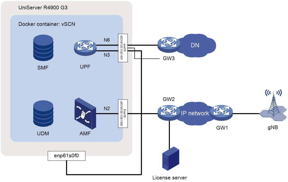
Planning IP addresses
During the vSCN installation process, multiple IP address segments are used. As shown in Table 8, H3C provides a vSCN IP address planning template, where the IP addresses for each device and interface are specified. Table 8 can be used in conjunction with Figure 15. You can edit the information based on the actual network configuration. Unless otherwise stated, this document uses Table 8 and Figure 15 as examples to describe the vSCN installation process.
Table 8 vSCN IP address planning
|
Device |
Interface |
IP address |
Remarks |
|
License Server |
N/A |
10.20.1.20/24 |
You can install the license server on a standalone server or the UniServer R4900 G3 that hosts the vSCN. For a successful registration of the vSCN software, make sure the license server and vSCN are reachable to each other. NOTE: · For how to install and use the license server, see H3C License Server Installation Guide and the online help provided with the vSCN. · For information about the license server version compatible the vSCN, see H3C vSCN5100 Release Notes. · For information about how to configure vSCN licenses, see H3C Mobile Communication Core Network Products Licensing Guide. |
|
vSCN5100 |
XGE1/0/0 (ens1f0 on the server). |
10.20.1.30/24 |
Management IP address of vSCN5100, used for logging in to the Web interface and communicating with the license server. |
|
XGE1/0/0 (ens1f0 on the server). |
10.20.2.10/24 |
N4 interface IP address, used for connecting to the 5GC control plane network elements. |
|
|
XGE1/0/1 (ens1f1 on the server). |
10.20.3.10/24 |
N3 interface IP address, used for sending and receiving user plane data between the base station and the core network. |
|
|
XGE1/0/1 (ens1f1 on the server). |
10.20.4.10/24 |
N6 interface IP address, used for sending and receiving user plane data between the core network and DN. |
|
|
Host |
Management interface enp61s0f0 |
10.20.1.20/24 |
Used for logging to in and managing H3Linux. When the license server is installed on the same server as vSCN, you can use this address as the license server's address. In this example, the host's management IP address is the same as the license server's address. |
|
|
NOTE: For planning and configuring the vSCN service-related interface IP addresses, see H3C vSCN5100 Smart Core Network Service Provisioning Guide. |
Installing the vSCN
Restrictions and guidelines
· Log in to H3Linux multiple times remotely via the console or SSH.
¡ Log in to H3Linux via the remote console. For more information, see "Logging in to H3Linux for the first time."
¡ Log in to H3Linux via SSH: Launch a terminal emulation program on the configuration terminal (such as MobaXterm or PuTTY), select SSH, and enter the IP address of the host management interface, the username and password for logging in to H3Linux. To facilitate user login, H3Linux has SSH service enabled.
· Unless otherwise specified, this document uses the root user to log in to H3Linux, and the default directory after login is /root.
· For the default user and password used to log in to the device, see "Logging in to H3Linux for the first time."
When H3Linux is running correctly and you do not need to use vSCN any more, you can delete the vSCN container by executing ./env/rmdocker.sh remove container name command in the /root directory. Then, delete the vSCN image tag by executing the docker rmi image tag command. To reuse vSCN, you can recreate a Docker container on H3Linux and install the vSCN in the new container.
The output from the commands depends on the server or software version.
Configuring HugePages
For a successful installation of the vSCN, first complete HugePages configuration as follows:
1. Edit the huge page configuration file.
a. Open the /etc/default/grub file by using the VIM editor.
[root@localhost ~]# vim /etc/default/grub
b. Press Shift+I to enter edit mode and edit the file as follows:
GRUB_TIMEOUT=5
GRUB_DISTRIBUTOR="$(sed 's, release .*$,,g' /etc/system-release)"
GRUB_DEFAULT=saved
GRUB_DISABLE_SUBMENU=true
GRUB_TERMINAL_OUTPUT="console"
GRUB_CMDLINE_LINUX="resume=/dev/mapper/h3linux-swap rd.lvm.lv=h3linux/root rd.lvm.lv=h3linux/swap crashkernel=512M <cf style=TerminalDisplayshading>default_hugepagesz=1G hugepagesz=1G hugepages=16</cf>"
GRUB_DISABLE_RECOVERY="true"
c. Press ESC to exit edit mode, then enter :wq to save and exit the VIM editor.
2. Select an option based on the server's BIOS boot mode to generate a startup configuration file from the /etc/default/grub file.
¡ If the system boots in UEFI mode, enter the following commands:
[root@localhost ~]# grub2-mkconfig -o /boot/efi/EFI/H3Linux/grub.cfg
Generating grub configuration file ...
Found linux image: /boot/vmlinuz-5.10.0-60.18.0.50.1.hl202.x86_64
Found initrd image: /boot/initramfs-5.10.0-60.18.0.50.1.hl202.x86_64.img
Adding boot menu entry for UEFI Firmware Settings ...
done
¡ If the system boots in Legacy mode, enter the following commands:
[root@node1 ~]# grub2-mkconfig -o /boot/grub2/grub.cfg
Generating grub configuration file ...
Found linux image: /boot/vmlinuz-3.10.0-862.el7.x86_64
Found initrd image: /boot/initramfs-3.10.0-862.el7.x86_64.img
Found linux image: /boot/vmlinuz-0-rescue-f2e062c5077847ae837b2f1cdb91104f
Found initrd image: /boot/initramfs-0-rescue-f2e062c5077847ae837b2f1cdb91104f.img
Done
3. Restart the server for the configuration to take effect.
[root@localhost ~]# reboot
4. Identify whether huge pages are configured successfully.
The output from the cat /proc/cmdline command depends on H3Linux version. You only need to focus on changes to the HugePage configuration.
[root@localhost ~]# cat /proc/cmdline
BOOT_IMAGE=/vmlinuz-5.10.0-60.18.0.50.1.hl202.x86_64 root=/dev/mapper/h3linux-root ro resume=/dev/mapper/h3linux-swap rd.lvm.lv=h3linux/root rd.lvm.lv=h3linux/swap crashkernel=512M default_hugepagesz=1G hugepagesz=1G hugepages=16
Creating the container for the vSCN and running the vSCN
|
|
CAUTION: To prevent the vSCN from becoming unavailable when the Docker service stops or experiences an anomaly, first add this file in the /etc/docker directory, and then execute the service docker restart command to restart the Docker service. |
1. Execute the docker import command in the /root directory to import the vSCN software package into the Docker image space.
[root@localhost ~]# docker import vSCN5100-CMW910-A5118.tar.gz vscn:v01
sha256:a579e957acdd46263fa65e986e7dab4c85f926ecddc8ed33650d5b821b73f032
v01 represents the image tag, which can contain only letters (case-sensitive) and digits. vscn represents the name of the image repository, which can contain only lowercase letters and digits.
2. Run the dockerrun.sh script in the /root/env directory to create a vSCN container.
[root@localhost ~]# cd env
[root@localhost env]# ./dockerrun.sh v01 vscn -c 1-9,20-29 --cgroup ControlPlane=8 -m 32768 -h 65536 --ifname ens1f0,ens1f1
bind vfio-pci to interfaces... ok
kernel.core_pattern = |/root/coredump.sh %p %P %i %I %u %g %d %s %t %h %e %E %c
starting docker container vscn
/dev/tty /dev/ttyS0 /dev/ttyS1 /dev/ttyS2 /dev/ttyS3
harddisk init...
ok
fsck.fat 4.1 (2017-01-24)
/disk/flash.img: 0 files, 1/2080259 clusters
about to fork child process, waiting until server is ready for connections.
forked process: 436
child process started successfully, parent exiting
scm init
Phase 0 finished!
Line con0 is available.
Press ENTER to get started.
Table 9 dockerrun.sh parameters
|
Parameter |
Description |
|
imageTag |
Image tag, v01 in this example. |
|
dockerName |
Container name, vscn in this example. |
|
-c { corelist | coremask } |
Allocates CPU information. Options are corelist and coremask. This example uses the corelist mode to allocate CPUs 1 through 9 and 20 through 29. You must allocate a minimum of two CPU cores. As a best practice, make sure the allocated CPUs are on the same NUMA node as the bound network adapter, and are not in use by another container. To locate CPU NUMA node information, execute the lscpu command. To obtain information about the NUMA node to which the network adapter belongs, execute the cat /sys/class/net/ens1f0/device/numa_node command. |
|
--cgroup ControlPlane |
Specifies the number of CPUs for the control plane. If multiple CPUs are allocated and the number for the control plane is not specified, only one CPU will be used for the control plane by default and the other CPUs are used for the user plane. To improve user login performance, use the --cgroup ControlPlane parameter to allocate multiple CPUs for the control plane. For example, when you run the ./dockerrun.sh v01 vscn -c 10-18 -m 32768 -h 32768 --cgroup ControlPlane=6 --ifname ens1f0,ens1f1 script, the system uses six CPUs for the control plane. You can specify the number of CPUs for the control plane only when you create a container. |
|
-m memsize |
Limits the memory size used by the container. If you do not specify this parameter, the default memory size is 2048M. In this example, the memory size is set to 32768M, and you can edit it as needed. To create a vSCN container, set the memory size to be 16384M or more. |
|
-h hdisksize |
Limits the disk size used by the container. If you do not specify this parameter, the default disk size is 2048M. In this example, the disk size is set to 32768M, and you can edit it as needed. To create a vSCN container, set the disk size to be 16384M or more. |
|
-d ehdisksize |
Limits the size of an additional disk used by the container to store call detail records. If you do not specify this parameter, the size of the additional disk is the same as the disk size. An additional 32GB disk can store up to 7,864,320 files, and an additional 64GB disk can store up to 15,728,640 files, with the capacity doubling accordingly. |
|
--ifname ifname-list |
Network interface names for the container. In this example, ens1f0 and ens1f1 are used. |
Logging in to the CLI of the vSCN
After the vSCN is installed, you can press Enter to log in to the vSCN CLI. To exit the vSCN CLI, press Ctrl+P and Ctrl+Q in sequence.
If you log in to the vSCN CLI again, you can execute the docker attach container_name command as a root user in any directory and then press Enter.
Configuring the vSCN at the CLI
|
|
IMPORTANT: · The document uses the vSCN interface Ten-GigabitEthernet1/0/0 with IP address 10.20.1.30/24 as an example to describe how to configure the IP address for logging in to the vSCN Web interface. To access the vSCN Web interface, select an appropriate interface based on your actual network setup and assign the planned IP address to it. · If Ten-GigabitEthernet1/0/0 on the vSCN already has another IP address configured, include the sub keyword in the ip address command. · Ten-GigabitEthernet1/0/0 and XGE1/0/0 are the same interface. |
1. Configure secondary IP address 10.20.1.30 on Ten-GigabitEthernet1/0/0 for logging in to the vSCN Web interface.
<H3C> system-view
[H3C] interface Ten- GigabitEthernet 1/ 0/0
[H3C-Ten-GigabitEthernet1/0/0] ip address 10.20.1.30 24 sub
[H3C-Ten-GigabitEthernet1/0/0] quit
2. Execute the save command to save the current configuration.
[H3C] save
The current configuration will be written to the device. Are you sure? [Y/N]:y
Please input the file name(*.cfg)[flash:/startup.cfg]
(To leave the existing filename unchanged, press the enter key):
flash:/startup.cfg exists, overwrite? [Y/N]:y
Validating file. Please wait...
Saved the current configuration to mainboard device successfully.
Deploying network elements
Network elements installed by default
· Version packages include base packages and plug-in packages. Base packages are installed by default and cannot be removed. Plug-in packages support installation and removing network elements at the CLI. The network elements that can be deployed include AMF, SMF, UDM, UDR, AUSF, NSSF, NRF, IWF, PCF, UPF, LMF, GMLC, IMS, and IMSHSS.
· After you install the vSCN, the following related network elements are installed by default: AMF, SMF, UDM, UDR, AUSF, NSSF, NRF, IWF, PCF, UPF, LMF, GMLC.
· Network elements IMS and IMSHSS are not installed by default.
Deploying network elements
You can install and remove network elements as needed. The commands for installing and removing network elements take effect only after you restart the vSCN.
By default, all network elements related to the vSCN are installed. You do not need to enter any commands after you install the system.
You can remove network elements from the CLI. For example, to remove the IWF network element, execute the following commands:
<H3C> system-view
[H3C] undo om install iwf
This operate need reboot, Do you want to reboot force without saving now? [Y/N]:Y
Deploying voice services
Deploy or unmount network elements as needed. The commands for installing and removing network elements take effect only after the device restarts.
1. Use the following commands to activate voice service features on the vSCN by installing the vSCN and related IMS network elements:
<H3C> system-view
[H3C] om install ims imshss
This operate need reboot, Do you want to reboot force without saving now? [Y/N]:Y
2. Use the following commands to reserve the IMS section and unmount the vSCN-related network elements:
<H3C> system-view
[H3C] undo om install amf smf udm udr ausf nssf nrf iwf pcf upf lmf gmlc
This operate need reboot, Do you want to reboot force without saving now? [Y/N]:N
[H3C] om install ims imshss
This operate need reboot, Do you want to reboot force without saving now? [Y/N]:Y
Logging in to the Web interface
Web browser requirements
· As a best practice, use the following Web browsers:
¡ Internet Explorer 10 or higher.
¡ Google Chrome 55 or higher.
· To access the Web interface, you must use the following browser settings:
¡ Accept the first-party cookies (cookies from the site you are accessing).
¡ Enable active scripting or JavaScript, depending on the Web browser.
· After you enable the proxy feature in your browser, you might not be able to access the Web interface correctly. You can disable the browser's proxy feature or set your device's IP address as an exception to the proxy settings, depending on the Web browser you are using.
· If you are using a Microsoft Internet Explorer browser, you must enable the following security settings:
¡ Run ActiveX controls and plug-ins.
¡ Script ActiveX controls marked safe for scripting.
· To ensure correct display of webpage contents after software upgrade or downgrade, clear data cached by the browser before you log in.
Restrictions and guidelines
· Enter a correct username and password when you log in to the Web interface. If you enter an incorrect username or password, the device will prompt a login failure. If you fail to enter the password in two attempts, you must enter the verification code provided by the device.
· The device comes with an administrator account named admin with password admin@SCN5100. To enhance security, the system will prompt for a password change at your first login. To log in to the system, you must change the password as prompted.
· The Web interface allows a maximum of 32 concurrent accesses.
Logging in to the Web interface for the first time
Use the following default settings for the first login.
· Username: admin
· Password: admin@SCN5100
To log in to the vSCN Web interface by using the factory default information:
1. Connect the vSCN to the local terminal.
Use an Ethernet cable to connect the configuration terminal to an interface configured with an IP address on the vSCN. The following uses Ten-GigabitEthernet 1/0/0 as an example.
2. Configure an IP address for the configuration terminal.
Make sure the local configuration terminal can communicate with Ten-GigabitEthernet 1/0/0. The following uses 10.20.1.2/24 as an example.
3. Launch the browser.
a. Open the browser, and then enter login information:
b. In the address bar, enter the IP address of Ten-GigabitEthernet 1/0/0.
- HTTP access—Enter the address in the http://ip-address:port or ip-address:port format.
- HTTPS access—Enter the address in the https://ip-address:port format.
The ip-address argument represents the IP address of the device. The port argument represents the HTTP or HTTPS service port. The default port number is 80 for HTTP and 443 for HTTPS. You do not need to enter the port number if you have not changed the service port setting.
The following uses 10.20.1.30 of Ten-GigabitEthernet 1/0/0 as an example.
4. Log in to the Web interface of vSCN.
a. On the login page, enter the default username (admin) and the default password (admin), and then click Log In.
Figure 16 Entering login information

b. Enter the new password as required, and then click OK.
Figure 17 Changing the password

|
|
NOTE: As a best practice, set a password that contains the following categories of characters: letters (case insensitive), digits, and special characters ~`!@#$%^&*()_+-={}|[]\:";'<>,./. Spaces are allowed. |
c. Enter the username and new password. Click Login.
Logging out of the Web interface
For security purposes, log out of the Web interface immediately after you finish your tasks.
Use either of the following methods to log out of the Web interface:
· Click admin/Exit in the upper right corner of the Web interface.
· Click ![]() in the upper
right corner of the page.
in the upper
right corner of the page.
The device does not automatically save the configuration when you log out of the Web interface. To prevent the loss of configuration when the device reboots, you must save the configuration. For how to save the configuration, see H3C vSCN5100 Virtual Smart Core Network Web-Based Configuration Guide.
