- Table of Contents
-
- 07-Layer 3—IP Routing Configuration Guide
- 00-Preface
- 01-Basic BGP configuration
- 02-Advanced BGP configuration
- 03-IPv6 policy-based routing configuration
- 04-IPv6 static routing configuration
- 05-Basic IP routing configuration
- 06-IS-IS configuration
- 07-OSPFv3 configuration
- 08-OSPF configuration
- 09-RIPng configuration
- 10-RIP configuration
- 11-RIR configuration
- 12-Policy-based routing configuration
- 13-Routing policy configuration
- 14-Static routing configuration
- Related Documents
-
| Title | Size | Download |
|---|---|---|
| 12-Policy-based routing configuration | 289.46 KB |
Contents
Restrictions and guidelines: PBR configuration
Setting match criteria for a node
Configuring actions for a node
Specifying a policy for local PBR
Specifying a policy for interface PBR
Specifying a policy for global PBR
Verifying PBR policy configuration
Displaying PBR configuration and statistics
Example: Configuring packet type-based local PBR
Example: Configuring packet type-based interface PBR
Example: Configuring packet length-based interface PBR
Example: Configuring source-IP-based interface PBR
Example: Configuring packet application-type-based interface PBR
Example: Configuring packet service-type-based interface PBR
Configuring PBR
About PBR
Policy-based routing (PBR) uses user-defined policies to route packets. You can define PBR policies for the system to take specified actions on the packets that match the specified criteria such as an ACL or a packet length. For example, you can set the next hop, output interface, default next hop, and default output interface.
Packet forwarding process
When the device receives a packet, the device searches the PBR policy for a matching node to forward that packet.
· If a matching node is found and its match mode is permit, the device performs the following operations:
a. Uses the next hops or output interfaces specified on the node to forward the packet.
b. Searches the routing table for a route (except the default route) to forward the packet if one of the following conditions exists:
- No next hops or output interfaces are specified on the node.
- Forwarding failed based on the next hops or output interfaces.
c. Uses the default next hops or default output interfaces specified on the node to forward the packet if one of the following conditions exists:
- No matching route was found in the routing table.
- The routing table-based forwarding failed.
d. Uses the default route to forward the packet if one of the following conditions exists:
- No default next hops or default output interfaces are specified on the node.
- The forwarding failed based on the default next hops or default output interfaces.
· The device performs routing table lookup to forward the packet in either of the following conditions:
¡ No matching node is found.
¡ A matching node is found, but its match mode is deny.
PBR types
PBR includes the following types:
· Local PBR—Guides the forwarding of locally generated packets, such as ICMP packets generated by using the ping command.
· Interface PBR—Guides the forwarding of packets received on an interface.
Policy
A policy includes match criteria and actions to be taken on the matching packets. A policy can have one or multiple nodes as follows:
· Each node is identified by a node number. A smaller node number has a higher priority.
· A node contains if-match and apply clauses. An if-match clause specifies a match criterion, and an apply clause specifies an action.
· A node has a match mode of permit or deny.
A policy compares packets with nodes in priority order. If a packet matches the criteria on a node, it is processed by the action on the node. If the packet does not match any criteria on the node, it goes to the next node for a match. If the packet does not match the criteria on any node, the device performs a routing table lookup.
Relationship between if-match clauses
On a node, you can specify multiple types of if-match clauses. For each type of the if-match clauses, the number of the clauses that can be specified for a node varies by device model.
To match a node, a packet must match all types of the if-match clauses for the node but only one if-match clause for each type.
Relationship between apply clauses
You can specify multiple apply clauses for a node, but some of them might not be executed. For more information about relationship between apply clauses, see "Configuring actions for a node."
Relationship between the match mode and clauses on the node
|
Does a packet match all the if-match clauses on the node? |
Match mode |
|
|
Permit |
Deny |
|
|
Yes. |
· If the node contains apply clauses, PBR executes the apply clauses on the node. ¡ If PBR-based forwarding succeeds, PBR does not compare the packet with the next node. ¡ If PBR-based forwarding fails and the apply continue clause is not configured, PBR does not compare the packet with the next node. ¡ If PBR-based forwarding fails and the apply continue clause is configured, PBR compares the packet with the next node. · If the node does not contain apply clauses, the device performs a routing table lookup for the packet. |
The device performs a routing table lookup for the packet. |
|
No. |
PBR compares the packet with the next node. |
PBR compares the packet with the next node. |
|
|
NOTE: A node that has no if-match clauses matches any packet. |
PBR and Track
PBR can work with the Track feature to dynamically adapt the availability status of an apply clause to the link status of a tracked object. The tracked object can be a next hop, output interface, default next hop, or default output interface.
· When the track entry associated with an object changes to Negative, the apply clause is invalid.
· When the track entry changes to Positive or NotReady, the apply clause is valid.
For more information about Track-PBR collaboration, see High Availability Configuration Guide.
Restrictions and guidelines: PBR configuration
If the device performs forwarding in software, PBR does not process IP packets destined for the local device.
If the device performs forwarding in hardware and a packet destined for it matches a PBR policy, PBR will execute the apply clauses in the policy, including the clause for forwarding. When you configure a PBR policy, be careful to avoid this situation.
PBR tasks at a glance
To configure PBR, perform the following tasks:
b. Setting match criteria for a node
c. Configuring actions for a node
2. Specifying a policy for PBR
Choose the following tasks as needed:
¡ Specifying a policy for local PBR
¡ Specifying a policy for interface PBR
¡ Specifying a policy for global PBR
Configuring a policy
Creating a node
1. Enter system view.
system-view
2. Create a node for a policy, and enter its view.
policy-based-route policy-name [ deny | permit ] node node-number
3. (Optional.) Configure a description for the policy node.
description text
By default, no description is configured for a policy node.
Setting match criteria for a node
Restrictions and guidelines
On a transport network device, you can configure PBR on the Layer 3 interface to guide the forwarding of packets based on VXLAN IDs. On a VTEP, you can configure PBR on the tunnel interface to guide the forwarding of packets based on VXLAN IDs.
Procedure
1. Enter system view.
system-view
2. Enter policy node view.
policy-based-route policy-name [ deny | permit ] node node-number
3. Set match criteria.
¡ Set an ACL match criterion.
if-match acl { acl-number | name acl-name }
By default, no ACL match criterion is set.
The ACL match criterion cannot match Layer 2 information.
¡ Set a packet length match criterion.
if-match packet-length min-len max-len
By default, no packet length match criterion is set.
¡ Set a source IP address match criterion for local PBR.
if-match source-ip { interface interface-type interface-number | [ vpn-instance vpn-instance-name ] ip-address }
By default, no source IP address match criterion is set for local PBR.
¡ Set application group match criteria.
if-match app-group app-group-name&<1-6>
By default, no application group match criteria are set.
Application group match criteria apply only to interface PBR.
¡ Set service object group match criteria.
if-match object-group service object-group-name&<1-6>
By default, no service object group match criteria are set.
Configuring actions for a node
About this task
The apply clauses allow you to specify the actions to be taken on matching packets on a node.
The following apply clauses determine the packet forwarding paths in a descending order:
· apply access-vpn
· apply next-hop
· apply output-interface
· apply default-next-hop
· apply default-output-interface
PBR supports the types of apply clauses shown in Table 1.
Table 1 Priorities and meanings of apply clauses
|
Clause |
Meaning |
Priority |
|
apply precedence |
Sets an IP precedence. |
This clause is always executed. |
|
apply ip-df df-value |
Sets the Don't Fragment (DF) bit in the IP header. |
This clause is always executed. |
|
apply loadshare { default-next-hop | default-output-interface | next-hop | output-interface } |
Enables load sharing among multiple next hops, output interfaces, default next hops, or default output interfaces. |
Multiple next hop, output interface, default next hop, or default output interface options operate in either primary/backup or load sharing mode. The following description uses multiple next hops as an example: · Primary/backup mode—A next hop is selected from all next hops in configuration order for packet forwarding, with all remaining next hops as backups. When the selected next hop fails, the next available next hop takes over. · Load sharing mode—Matching traffic is distributed across the available next hops. If the traffic does not match any fast forwarding entries, per-packet load sharing is performed. If the traffic matches a fast forwarding entry, per-flow load sharing is performed. By default, the primary/backup mode applies. For the load sharing mode to take effect, make sure multiple next hops, output interfaces, default next hops, or default output interfaces are set in the policy, depending on the redundancy scenario. |
|
apply access-vpn |
Specifies the forwarding tables that can be used for the matching packets. |
Use this clause only in special scenarios that require sending packets received from one network to another network, for example, from a VPN to the public network, or from one VPN to another VPN. The device forwards the matching packets by using the first available forwarding table selected in the order in which they are specified. |
|
apply remark-vpn |
Enables VPN remark action. |
VPN remark action marks the matching packets as belonging to the VPN instance to which they are forwarded based on the apply access-vpn vpn-instance command. All subsequent service modules of PBR handle the packets as belonging to the re-marked VPN instance. If the VPN remark action is not enabled, the forwarded matching packets are marked as belonging to the VPN instance or the public network from which they were received. VPN remark action applies only to packets that have been successfully forwarded based on the apply access-vpn vpn-instance command. |
|
apply next-hop and apply output-interface |
Sets next hops and output interfaces. |
If multiple clauses are configured, only the clause with the highest priority is executed. |
|
apply default-next-hop and apply default-output-interface |
Sets default next hops and default output interfaces. |
If multiple clauses are configured, only the clause with the highest priority is executed. The clauses take effect only in the following cases: · No next hops or output interfaces are set, or the next hops and output interfaces are invalid. · The packet does not match any route in the routing table. |
|
apply continue |
Compares packets with the next node upon failure on the current node. |
The apply continue clause applies when either of the following conditions exist: · None of the clauses that determine the packet forwarding paths is configured. · A clause that determines the packet forwarding paths is configured, but it has become invalid. Then, a routing table lookup also fails for the matching packet. NOTE: A clause might become invalid because the specified next hop is unreachable, packets cannot be forwarded in the specified VPN instance, the SRv6 TE policy is invalid, or the specified output interface is down. |
Restrictions and guidelines
For outbound PBR, you can specify only one next hop and the next hop must be directly connected.
If you specify a next hop or default next hop, PBR periodically performs a lookup in the FIB table to determine its availability. Temporary service interruption might occur if PBR does not update the route immediately after its availability status changes.
PBR can guide packets that match a service chain only to VXLAN tunnels in IPv4 networks.
Configuring actions to modify packet fields
1. Enter system view.
system-view
2. Enter policy node view.
policy-based-route policy-name [ deny | permit ] node node-number
3. Set an IP precedence.
apply precedence { type | value }
By default, no IP precedence is specified.
4. Set the DF bit in the IP header.
apply ip-df df-value
By default, the DF bit in the IP header is not set.
Configuring actions to direct packet forwarding
1. Enter system view.
system-view
2. Enter policy node view.
policy-based-route policy-name [ deny | permit ] node node-number
3. Configure actions.
¡ Specify the forwarding tables that can be used for the matching packets.
apply access-vpn { public | vpn-instance vpn-instance-name&<1-4> }
By default, the device forwards matching packets by using the forwarding table for the network from which the packets are received.
You can repeat this command to specify the forwarding tables for the public network and VPN instances. The device forwards the matching packets by using the first available forwarding table selected in the order in which they are specified.
¡ Enable VPN remark action to mark the matching packets as belonging to the VPN instance to which they are forwarded based on the apply access-vpn vpn-instance command.
apply remark-vpn
By default, VPN remark action is not configured
¡ Set next hops.
apply next-hop [ vpn-instance vpn-instance-name | inbound-vpn ] { ip-address [ direct ] [ track track-entry-number ] [ weight weight-value ] }&<1-4>
By default, no next hops are specified.
On a node, you can specify a maximum of four next hops for backup or load sharing in one command line or by executing this command multiple times.
If multiple next hops on the same subnet are specified for backup, the device first uses the subnet route for the next hops to forward packets when the primary next hop fails. If the subnet route is not available, the device selects a backup next hop.
¡ Enable load sharing among multiple next hops.
apply loadshare next-hop
By default, the next hops operate in primary/backup mode.
¡ Set output interfaces.
apply output-interface { interface-type interface-number [ track track-entry-number ] }&<1-4>
By default, no output interfaces are specified.
On a node, you can specify a maximum of four output interfaces for backup or load sharing in one command line or by executing this command multiple times.
¡ Enable load sharing among multiple output interfaces.
apply loadshare output-interface
By default, the output interfaces operate in primary/backup mode.
¡ Set default next hops.
apply default-next-hop [ vpn-instance vpn-instance-name | inbound-vpn ] { ip-address [ direct ] [ track track-entry-number ] }&<1-4>
By default, no default next hops are specified.
On a node, you can specify a maximum of four default next hops for backup or load sharing in one command line or by executing this command multiple times.
¡ Enable load sharing among multiple default next hops.
apply loadshare default-next-hop
By default, the default next hops operate in primary/backup mode.
¡ Set default output interfaces.
apply default-output-interface { interface-type interface-number [ track track-entry-number ] }&<1-4>
By default, no default output interfaces are specified.
On a node, you can specify a maximum of four default output interfaces for backup or load sharing in one command line or by executing this command multiple times.
¡ Enable load sharing among multiple default output interfaces.
apply loadshare default-output-interface
By default, the default output interfaces operate in primary/backup mode.
Comparing packets with the next node upon match failure on the current node
1. Enter system view.
system-view
2. Enter policy node view.
policy-based-route policy-name [ deny | permit ] node node-number
3. Compare packets with the next node upon match failure on the current node.
apply continue
By default, PBR does not compare packets with the next node upon match failure on the current node.
This command takes effect only when the match mode of the node is permit.
Specifying a policy for PBR
Specifying a policy for local PBR
About this task
Perform this task to specify a policy for local PBR to guide the forwarding of locally generated packets.
Restrictions and guidelines
You can specify only one policy for local PBR and must make sure the specified policy already exists. Before you apply a new policy, you must first remove the current policy.
Local PBR might affect local services such as ping and Telnet. When you use local PBR, make sure you fully understand its impact on local services of the device.
Procedure
1. Enter system view.
system-view
2. Specify a policy for local PBR.
ip local policy-based-route policy-name
By default, local PBR is not enabled.
Specifying a policy for interface PBR
About this task
Perform this task to apply a policy to an interface to guide the forwarding of packets received on the interface.
Restrictions and guidelines
You can apply only one policy to an interface and must make sure the specified policy already exists. Before you can apply a new interface PBR policy to an interface, you must first remove the current policy from the interface.
You can apply a policy to multiple interfaces.
In a VXLAN IP gateway or EVPN gateway deployment, when you apply a policy to an interface on a border gateway, follow these restrictions and guidelines:
· If the interface is a Layer 3 Ethernet interface, the policy is also applied to its subinterfaces. For more information about VXLAN IP gateway deployment, see VXLAN Configuration Guide.
· If the interface is a Layer 3 aggregate interface, the policy is also applied to its subinterfaces. For more information about EVPN gateway deployment, see EVPN Configuration Guide.
Procedure
1. Enter system view.
system-view
2. Enter interface view.
interface interface-type interface-number
3. Specify a policy for interface PBR.
ip policy-based-route policy-name
By default, no interface policy is applied to an interface.
Specifying a policy for global PBR
About this task
Perform this task to apply a policy to all interfaces on the device to guide the forwarding of packets received on the interfaces.
Restrictions and guidelines
You can apply only one policy for global PBR and the specified policy must already exist. Before you can apply a new policy, you must first remove the current policy.
Interface PBR takes precedence over global PBR on an interface. When they are both configured and packets fail to match the interface PBR policy, global PBR applies.
Procedure
1. Enter system view.
system-view
2. Specify a policy for global PBR.
ip global policy-based-route policy-name
By default, no policy is specified for global PBR.
Verifying and maintaining PBR
Verifying PBR policy configuration
To display PBR policy information, execute the following command in any view:
display ip policy-based-route [ policy policy-name ]
Displaying PBR configuration and statistics
Perform display tasks in any view.
· Display PBR configuration.
display ip policy-based-route setup
· Display local PBR configuration and statistics.
display ip policy-based-route local [ slot slot-number ]
· Display global PBR configuration and statistics
display ip policy-based-route global [ slot slot-number ]
· Display interface PBR configuration and statistics.
display ip policy-based-route interface interface-type interface-number [ slot slot-number ]
Clearing PBR statistics
To clear PBR statistics, execute the following command in user view:
reset ip policy-based-route statistics [ policy policy-name ]
PBR configuration examples
Example: Configuring packet type-based local PBR
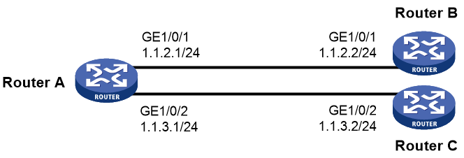
Network configuration
As shown in Figure 1, Router B and Router C do not have a route to reach each other.
Configure PBR on Router A to forward all TCP packets to the next hop 1.1.2.2 (Router B).
Procedure
1. Configure Router A:
# Configure the IP addresses of GigabitEthernet 1/0/1 and GigabitEthernet 1/0/2.
<RouterA> system-view
[RouterA] interface gigabitethernet 1/0/1
[RouterA-GigabitEthernet1/0/1] ip address 1.1.2.1 24
[RouterA-GigabitEthernet1/0/1] quit
[RouterA] interface gigabitethernet 1/0/2
[RouterA-GigabitEthernet1/0/2] ip address 1.1.3.1 24
[RouterA-GigabitEthernet1/0/2] quit
# Configure ACL 3101 to match TCP packets.
[RouterA] acl advanced 3101
[RouterA-acl-ipv4-adv-3101] rule permit tcp
[RouterA-acl-ipv4-adv-3101] quit
# Configure Node 5 for the policy aaa to forward TCP packets to next hop 1.1.2.2.
[RouterA] policy-based-route aaa permit node 5
[RouterA-pbr-aaa-5] if-match acl 3101
[RouterA-pbr-aaa-5] apply next-hop 1.1.2.2
[RouterA-pbr-aaa-5] quit
# Configure local PBR by applying the policy aaa to Router A.
[RouterA] ip local policy-based-route aaa
2. On Router B, configure the IP address of GigabitEthernet 1/0/1.
<RouterB> system-view
[RouterB] interface gigabitethernet 1/0/1
[RouterB-GigabitEthernet1/0/1] ip address 1.1.2.2 24
3. On Router C, configure the IP address of GigabitEthernet 1/0/2.
<RouterC> system-view
[RouterC] interface gigabitethernet 1/0/2
[RouterC-GigabitEthernet1/0/2] ip address 1.1.3.2 24
Verifying the configuration
1. Perform telnet operations to verify that local PBR on Router A operates as configured to forward the matching TCP packets to the next hop 1.1.2.2 (Router B), as follows:
# Verify that you can telnet to Router B from Router A successfully. (Details not shown.)
# Verify that you cannot telnet to Router C from Router A. (Details not shown.)
2. Verify that Router A forwards packets other than TCP packets through GigabitEthernet 1/0/2. For example, verify that you can ping Router C from Router A. (Details not shown.)
Example: Configuring packet type-based interface PBR
Network configuration
As shown in Figure 2, Router B and Router C do not have a route to reach each other.
Configure PBR on Router A to forward all TCP packets received on GigabitEthernet 1/0/1 to the next hop 1.1.2.2 (Router B).

Procedure
1. Configure IP addresses and unicast routing protocol settings to make sure Router B and Router C can reach Host A. (Details not shown.)
2. Configure Router A:
# Configure ACL 3101 to match TCP packets.
[RouterA] acl advanced 3101
[RouterA-acl-ipv4-adv-3101] rule permit tcp
[RouterA-acl-ipv4-adv-3101] quit
# Configure Node 5 for the policy aaa to forward TCP packets to next hop 1.1.2.2.
[RouterA] policy-based-route aaa permit node 5
[RouterA-pbr-aaa-5] if-match acl 3101
[RouterA-pbr-aaa-5] apply next-hop 1.1.2.2
[RouterA-pbr-aaa-5] quit
# Configure interface PBR by applying the policy aaa to GigabitEthernet 1/0/1.
[RouterA] interface gigabitethernet 1/0/1
[RouterA-GigabitEthernet1/0/1] ip policy-based-route aaa
[RouterA-GigabitEthernet1/0/1] quit
Verifying the configuration
1. Perform telnet operations to verify that interface PBR on Router A operates as configured to forward the matching TCP packets to the next hop 1.1.2.2 (Router B), as follows:
# Verify that you can telnet to Router B from Host A successfully. (Details not shown.)
# Verify that you cannot telnet to Router C from Host A. (Details not shown.)
2. Verify that Router A forwards packets other than TCP packets through GigabitEthernet 1/0/3. For example, verify that you can ping Router C from Host A. (Details not shown.)
Example: Configuring packet length-based interface PBR
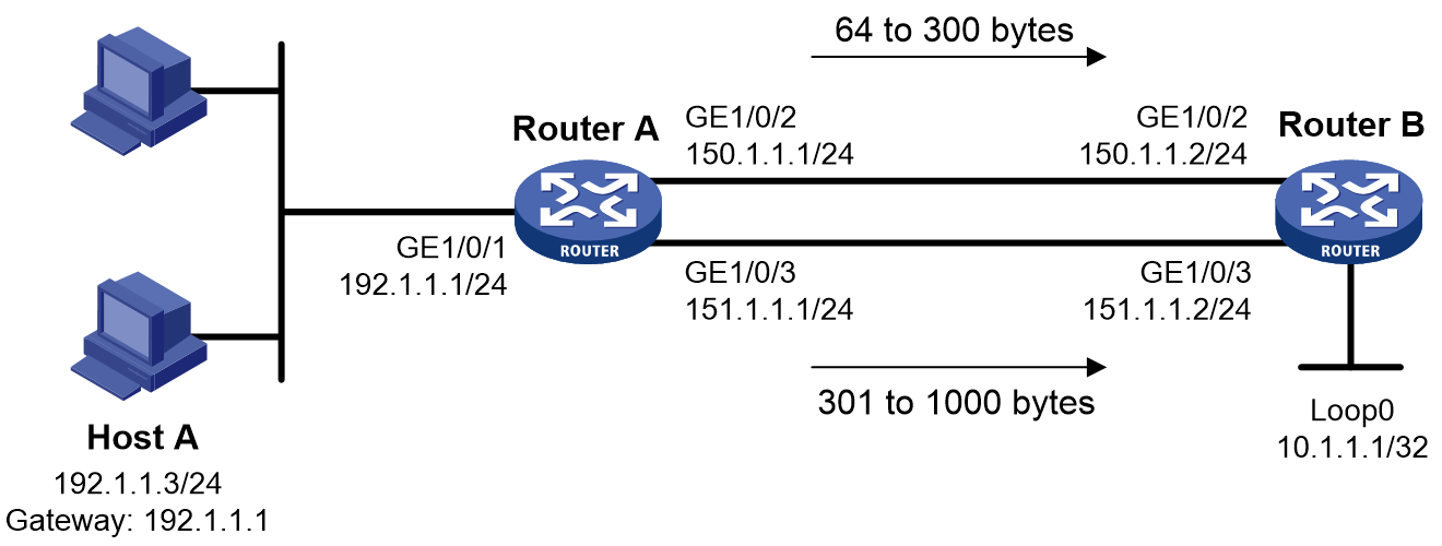
Network configuration
As shown in Figure 3, configure interface PBR to guide the forwarding of packets received on GigabitEthernet 1/0/1 of Router A as follows:
· Set the next hop of packets with a length of 64 to 300 bytes to 150.1.1.2/24.
· Set the next hop of packets with a length of 301 to 1000 bytes to 151.1.1.2/24.
Procedure
1. Configure IP addresses and unicast routing protocol settings to make sure the devices each have a route to reach one another. (Details not shown.)
2. Configure Router A:
# Configure Node 10 for the policy lab1 to forward packets with a length of 64 to 300 bytes to the next hop 150.1.1.2.
[RouterA] policy-based-route lab1 permit node 10
[RouterA-pbr-lab1-10] if-match packet-length 64 300
[RouterA-pbr-lab1-10] apply next-hop 150.1.1.2
[RouterA-pbr-lab1-10] quit
# Configure Node 20 for the policy lab1 to forward packets with a length of 301 to 1000 bytes to the next hop 151.1.1.2.
[RouterA] policy-based-route lab1 permit node 20
[RouterA-pbr-lab1-20] if-match packet-length 301 1000
[RouterA-pbr-lab1-20] apply next-hop 151.1.1.2
[RouterA-pbr-lab1-20] quit
# Configure interface PBR by applying the policy lab1 to GigabitEthernet 1/0/1.
[RouterA] interface gigabitethernet 1/0/1
[RouterA-GigabitEthernet1/0/1] ip policy-based-route lab1
[RouterA-GigabitEthernet1/0/1] quit
Verifying the configuration
# Execute the debugging ip policy-based-route command on Router A.
<RouterA> debugging ip policy-based-route
<RouterA> terminal logging level 7
<RouterA> terminal monitor
# Ping Loopback 0 of Router B from Host A, and set the data length to 64 bytes. In this way, the total length of the data packet is in the range of 64 to 300 bytes.
C:\>ping –n 1 -l 64 10.1.1.1
Pinging 10.1.1.1 with 64 bytes of data:
Reply from 10.1.1.1: bytes=64 time=1ms TTL=64
Ping statistics for 10.1.1.1:
Packets: Sent = 1, Received = 1, Lost = 0 (0% loss),
Approximate round trip times in milli-seconds:
Minimum = 1ms, Maximum = 1ms, Average = 1ms
The debugging information about PBR displayed on Router A is as follows:
<RouterA>
*Jun 26 12:04:33:519 2012 RouterA PBR4/7/PBR Forward Info: -MDC=1; Policy:lab1, Node:
10,match succeeded.
*Jun 26 12:04:33:519 2012 RouterA PBR4/7/PBR Forward Info: -MDC=1; apply next-hop 150
.1.1.2.
The output shows that Router A sets the next hop for the received packets to 150.1.1.2 according to PBR. The packets are forwarded through GigabitEthernet 1/0/2.
# Ping Loopback 0 of Router B from Host A, and set the data length to 300 bytes. In this way, the total length of the data packet is in the range of 301 to 1000 bytes.
C:\> ping –n 1 -l 300 10.1.1.1
Pinging 10.1.1.1 with 300 bytes of data:
Reply from 10.1.1.1: bytes=300 time=1ms TTL=64
Ping statistics for 10.1.1.1:
Packets: Sent = 1, Received = 1, Lost = 0 (0% loss),
Approximate round trip times in milli-seconds:
Minimum = 1ms, Maximum = 1ms, Average = 1ms
The debugging information about PBR displayed on Router A is as follows:
<RouterA>
*Jun 26 12:20:33:610 2012 RouterA PBR4/7/PBR Forward Info: -MDC=1; Policy:lab1, Node:
20,match succeeded.
*Jun 26 12:20:33:610 2012 RouterA PBR4/7/PBR Forward Info: -MDC=1; apply next-hop 151
.1.1.2.
The output shows that Router A sets the next hop for the received packets to 151.1.1.2 according to PBR. The packets are forwarded through GigabitEthernet 1/0/3.
Example: Configuring source-IP-based interface PBR
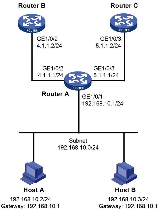
Network configuration
As shown in Figure 4, Router B and Router C do not have a route to reach each other.
Configure interface PBR to guide the forwarding of packets received on GigabitEthernet 1/0/1 of Router A as follows:
· Set the next hop of packets sourced from 192.168.10.2 to 4.1.1.2/24.
· Set the next hop of other packets to 5.1.1.2/24.
Procedure
1. Configure IP addresses and unicast routing protocol settings to make sure Router B can reach Host A and Host B, and Router C can reach Host A and Host B. (Details not shown.)
2. Configure Router A:
# Configure ACL 2000 to match packets sourced from 192.168.10.2.
[RouterA] acl basic 2000
[RouterA-acl-ipv4-basic-2000] rule 10 permit source 192.168.10.2 0
[RouterA-acl-ipv4-basic-2000] quit
# Configure Node 0 for the policy aaa to forward packets sourced from 192.168.10.2 to next hop 4.1.1.2. Configure Node 1 for the policy aaa to forward other packets to next hop 5.1.1.2.
[RouterA] policy-based-route aaa permit node 0
[RouterA-pbr-aaa-0] if-match acl 2000
[RouterA-pbr-aaa-0] apply next-hop 4.1.1.2
[RouterA-pbr-aaa-0] quit
[RouterA] policy-based-route aaa permit node 1
[RouterA-pbr-aaa-1] apply next-hop 5.1.1.2
[RouterA-pbr-aaa-1] quit
# Configure interface PBR by applying the policy aaa to GigabitEthernet 1/0/1.
[RouterA] interface gigabitethernet 1/0/1
[RouterA-GigabitEthernet1/0/1] ip policy-based-route aaa
[RouterA-GigabitEthernet1/0/1] quit
Verifying the configuration
1. Verify that interface PBR on Router A operates as configured to forward packets sourced from 192.168.10.2 to the next hop 4.1.1.2 and packets sourced from 192.168.10.3 to the next hop 5.1.1.2:
# Configure IP address 192.168.10.3/24 for Host B, and specify its gateway address as 192.168.10.1. (Details not shown.)
# Verify that you can ping Router B from Host A. (Details not shown.)
# Verify that you can ping Router C from Host B. (Details not shown.)
# Verify that you cannot ping Router B from Host B. (Details not shown.)
# Verify that you cannot ping Router C from Host A. (Details not shown.)
Example: Configuring packet application-type-based interface PBR
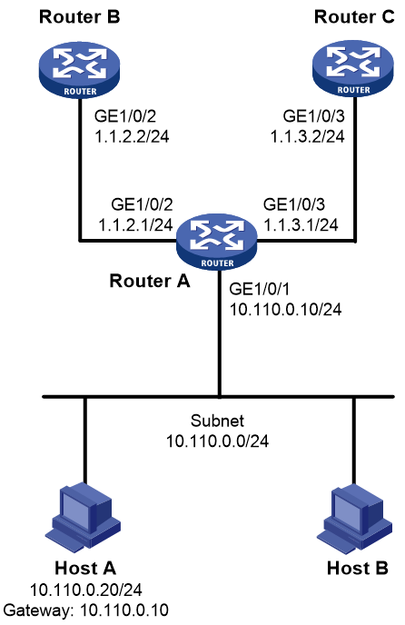
Network configuration
As shown in Figure 5, Router B and Router C do not have a route to reach each other.
Configure interface PBR on Router A to forward all HTTP packets received on GigabitEthernet 1/0/1 to the next hop 1.1.2.2/24 (Router B).

Procedure
1. Configure IP addresses and unicast routing protocol settings to make sure Router B and Router C can reach Host A. (Details not shown.)
2. Configure Router A:
# Create the application group http to match HTTP packets.
[RouterA] app-group http
[RouterA-app-group-http] include application http
[RouterA-app-group-http] quit
# Configure Node 5 for the policy aaa, and specify the application group http for the policy node to forward HTTP packets to next hop 1.1.2.2.
[RouterA] policy-based-route aaa permit node 5
[RouterA-pbr-aaa-5] if-match app-group http
[RouterA-pbr-aaa-5] apply next-hop 1.1.2.2
[RouterA-pbr-aaa-5] quit
# Configure interface PBR by applying the policy aaa to GigabitEthernet 1/0/1.
[RouterA] interface gigabitethernet 1/0/1
[RouterA-GigabitEthernet1/0/1] ip policy-based-route aaa
[RouterA-GigabitEthernet1/0/1] quit
Verifying the configuration
1. Perform Web logins to verify that interface PBR on Router A operates as configured to forward the matching HTTP packets to the next hop 1.1.2.2 (Router B), as follows:
# Verify that you can log in to Router B from Host A successfully. (Details not shown.)
# Verify that you cannot log in to Router C from Host A. (Details not shown.)
2. Verify that Router A forwards packets other than HTTP packets through GigabitEthernet 1/0/3. For example, verify that you can ping Router C from Host A. (Details not shown.)
Example: Configuring packet service-type-based interface PBR
Network configuration
As shown in Figure 6, Router B and Router C do not have a route to reach each other.
Configure interface PBR on Router A to forward all FTP packets received on GigabitEthernet 1/0/1 to the next hop 1.1.2.2/24 (Router B).
Procedure
1. Configure IP addresses and unicast routing protocol settings to make sure Router B and Router C can reach Host A. (Details not shown.)
2. Configure Router A:
# Configure Node 5 for the policy aaa, and specify the system-predefined service object group ftp for the policy node to forward FTP packets to next hop 1.1.2.2.
[RouterA] policy-based-route aaa permit node 5
[RouterA-pbr-aaa-5] if-match object-group service ftp
[RouterA-pbr-aaa-5] apply next-hop 1.1.2.2
[RouterA-pbr-aaa-5] quit
# Configure interface PBR by applying the policy aaa to GigabitEthernet 1/0/1.
[RouterA] interface gigabitethernet 1/0/1
[RouterA-GigabitEthernet1/0/1] ip policy-based-route aaa
[RouterA-GigabitEthernet1/0/1] quit
Verifying the configuration
1. Perform logins through FTP to verify that interface PBR on Router A operates as configured to forward the matching FTP packets to the next hop 1.1.2.2 (Router B), as follows:
# Verify that you can log in to Router B from Host A successfully. (Details not shown.)
# Verify that you cannot log in to Router C from Host A. (Details not shown.)
2. Verify that Router A forwards packets other than FTP packets through GigabitEthernet 1/0/3. For example, verify that you can ping Router C from Host A. (Details not shown.)
