- Table of Contents
- Related Documents
-
| Title | Size | Download |
|---|---|---|
| 01-vSystem configuration | 369.18 KB |
Contents
Default vSystem and non-default vSystems
Default vSystem users and non-default vSystem users
Features supported on non-default vSystems
Restrictions and guidelines: vSystem configuration
Assigning interfaces and VLANs to a vSystem
Assigning interfaces to a vSystem
Limiting resource use for a vSystem
Setting the maximum number of security policy rules
Setting the upper limit of the session establishment rate
Setting the maximum number of concurrent sessions
Configuring inbound throughput limiting
Configuring a vSystem interface for a vSystem
Display and maintenance commands for vSystems
vSystem configuration examples
Example: Using vSystems as cloud gateways
Configuring vSystems
About vSystems
vSystem is a lightweight virtualization technology that divides a physical device into multiple independent logical devices. Each vSystem acts as a real device to provide services and has independent interfaces, VLANs, routing table entries, address ranges, policies, and users or user groups. vSystems consume less resources than contexts, so the device can use vSystems to achieve network isolation for more tenants. For more information about context, see "Configuring contexts."
vSystem applications
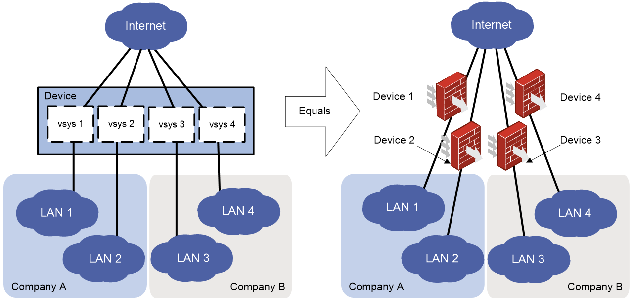
As shown in Figure 1, LAN 1, LAN 2, LAN 3, and LAN 4 are connected to the Internet through the same device. LAN 1 and LAN 2 belong to Company A, and LAN 3 and LAN 4 belong to Company B. To provide secure access services for the four LANs, you can deploy a single physical device and configure a vSystem for each LAN on the device. The administrator of each LAN can only log in to and manage its own vSystem without affecting other LANs. This has the same effect as deploying a separate device for each LAN.
Default vSystem and non-default vSystems
The device itself is considered as the default vSystem. The configuration on the device is equivalent to that on the default vSystem. The default vSystem is system defined and cannot be deleted. The default vSystem manages all resources of the device.
The vSystems newly created are non-default vSystem. You can assign the interface and VLAN resources to non-default vSystems, and specify the usage limits on other resources. Administrators of non-default vSystems can only use resources assigned to their own vSystems. They cannot use free resources or create other vSystems. Resources that are not assigned to any non-default vSystems belong to the default vSystem.
Default vSystem users and non-default vSystem users
The users created in the default vSystem are the default vSystem users. A default vSystem user can log in to any non-default vSystem to configure services.
The users created in the non-default vSystems are the non-default vSystem users. A non-default vSystem user can only log in to the non-default vSystem where it belongs. The non-default vSystems only support some features. For the supported features by non-default vSystems, see "Features supported on non-default vSystem."
Unless otherwise specified, the term "vSystem" in the following contents refers to a non-default vSystem.
vSystem benefits
vSystem provides the following benefits:
· Effective use of hardware resources—A device can provide independent services for multiple organizations, saving energy consumption and management costs.
· Role-based management—You can use the default vSystem user role or different non-default vSystem user roles to manage the resources.
· Independent policy settings and routing table entries—The users with overlapping address spaces still can communicate normally.
· Fixed interface and VLAN resources and limited usage of other resources—A vSystem with busy services will not affect the services of other vSystems.
· Traffic isolation—The vSystems can visit each other securely.
Features supported on non-default vSystems
Table 1 lists the features partially or fully supported on non-default vSystems. If a feature is partially supported on non-default vSystems, see the command reference or configuration guide for that feature for support details.
Device support for these features varies by device model.
|
|
NOTE: The vpn-instance keyword is not available on vSystems. |
Table 1 Support of non-default vSystems for features
|
Feature name |
Support status |
|
|
Fundamentals |
CLI |
Partial |
|
RBAC |
Partial |
|
|
Configuration file management |
Partial |
|
|
Device management |
Partial |
|
|
Interface |
Ethernet interfaces |
Partial |
|
Loopback, null, and inloopback interfaces |
Partial |
|
|
Layer 2—LAN switching |
Ethernet link aggregation |
Partial |
|
VLAN |
Partial |
|
|
Layer 3—IP services |
ARP |
Partial |
|
IP addressing |
Partial |
|
|
NAT |
Partial |
|
|
IP forwarding basics |
Partial |
|
|
Fast forwarding |
Partial |
|
|
Adjacency table |
Full |
|
|
IPv6 basics |
Partial |
|
|
IPv6 fast forwarding |
Partial |
|
|
AFT |
Partial |
|
|
Layer 3—IP routing |
IP routing basics |
Partial |
|
Static routing |
Partial |
|
|
OSPF |
Partial |
|
|
BGP |
Partial |
|
|
IPv6 static routing |
Partial |
|
|
OSPFv3 |
Partial |
|
|
IP multicast |
Multicast routing and forwarding |
Partial |
|
IGMP |
Partial |
|
|
PIM |
Partial |
|
|
IPv6 multicast routing and forwarding |
Partial |
|
|
MLD |
Partial |
|
|
IPv6 PIM |
Partial |
|
|
ACL and QoS |
ACL |
Partial |
|
Time range |
Full |
|
|
QoS |
Partial |
|
|
Security |
Security zone |
Full |
|
AAA |
Partial |
|
|
Public key |
Full |
|
|
PKI |
Partial |
|
|
IPsec |
Partial |
|
|
IKE |
Partial |
|
|
SSL |
Full |
|
|
ASPF |
Full |
|
|
Session management |
Partial |
|
|
Connection limit |
Full |
|
|
Object group |
Full |
|
|
Security policy |
Partial |
|
|
Attack detection and prevention |
Partial |
|
|
ND attack defense |
Partial |
|
|
Zero trust |
SDP zero trust |
Full |
|
Network management and monitoring |
System maintenance and debugging |
Partial |
|
Fast log output |
Partial |
|
|
Flow log |
Partial |
|
|
Information center |
Partial |
|
|
Internet access behavior management |
Bandwidth management |
Partial |
|
Application audit and management |
Full |
|
|
Load balancing |
Server load balancing |
Partial |
Restrictions and guidelines: vSystem configuration
If you create and configure non-default vSystems on a device that has multiple security engines, the processing performance of the security engines cannot be effectively utilized. As a best practice, create and configure a non-default context, assign the configured context to a security engine group, and then create and configure non-default vSystems on the non-default context. For more information about contexts and security engines, see "Configuring contexts."
|
|
NOTE: The default vSystem supports all the commands listed in the document and the non-default vSystems support some of the commands in the document. For the supported commands by non-default vSystems, see vSystem in Virtual Technologies Command Reference. |
vSystem tasks at a glance
To configure vSystems, perform the following tasks:
2. Assigning interfaces and VLANs to a vSystem
a. Assigning interfaces to a vSystem
b. Assigning VLANs to a vSystem
3. (Optional.) Limiting resource use for a vSystem
a. Setting the maximum number of security policy rules
b. Setting the upper limit of the session establishment rate
c. Setting the maximum number of concurrent sessions
d. Configuring inbound throughput limiting
4. Saving vSystem configuration
6. (Optional.) Configuring a vSystem interface for a vSystem
Creating vSystems
Restrictions and guidelines
When you create a vSystem, a VPN instance with the same name will be created and the created vSystem will be bound to the VPN instance automatically. Make sure the vSystem name is not the same as the existing VPN instance name.
Procedure
1. Enter system view.
system-view
2. Create a vSystem and enter its view.
vsys vsys-name [ id vsys-id ]
By default, a default vSystem exists. The vSystem name is Admin and the vSystem ID is 1.
3. (Optional.) Configure a description for the vSystem.
description text
By default, the description of the default vSystem is Default, and non-default vSystems do not have a description.
Assigning interfaces and VLANs to a vSystem
Assigning interfaces to a vSystem
About this task
By default, all interfaces belong to the default vSystem. A non-default vSystem cannot use any interfaces. To enable a non-default vSystem to communicate, you must assign it an interface.
You can allocate an interface to a vSystem in shared mode or exclusive mode.
· In exclusive mode, the interface can be used only by that vSystem. You can view the interface and execute supported commands for it after logging in to the vSystem.
· In shared mode, the interface can be used by multiple vSystems. A virtual interface with the same name as that interface is created and assigned unique MAC and IP addresses in each vSystem. The device distributes the traffic received by the shared interface to those virtual interfaces for processing, and the virtual interfaces send processed outgoing traffic to the shared interface for forwarding. This allocate mode improves interface utilization.
You can view the shared interface and execute supported commands for it after logging in to the default vSystem. In the non-default vSystems sharing the interface, you can view the virtual interfaces and execute the shutdown, description, network, and security commands for them.
You can assign the following interfaces to non-default vSystems:
· Layer 3 physical interfaces.
· Layer 3 physical subinterfaces.
· Layer 3 aggregate interfaces.
· Layer 3 aggregate subinterfaces.
· Layer 3 Reth interfaces.
· Layer 3 Reth subinterfaces.
· Tunnel interfaces.
· Loopback interfaces.
· SSL VPN AC interfaces.
After you assigning an interface to a non-default vSystem, only the non-default vSystem can use the interface.
Restrictions and guidelines
Do not assign the interfaces that are bound with VPN instances to vSystems. Do not bind the interfaces that are assigned to vSystems with VPN instances.
To exclusively allocate a shared interface to a vSystem, first delete the shared allocation configuration.
Procedure
1. Enter system view.
system-view
2. Enter vSystem view.
vsys vsys-name
3. Assign an interface to the vSystem.
allocate interface interface-type interface-number [ share ]
By default, all interfaces belong to the default vSystem. A non-default vSystem cannot use any interfaces.
Assigning VLANs to a vSystem
About this task
By default, all VLANs belong to the default vSystem. A non-default vSystem cannot use any VLANs. To enable a non-default vSystem to communicate, you must assign it a VLAN.
After assigning a VLAN to a non-default vSystem, the associated VLAN interfaces will be assigned to the non-default vSystem automatically, and only the non-default vSystem can use the VLAN.
After a VLAN is assigned to a non-default vSystem, the vSystem can use Layer 2 interfaces in the VLAN.
Procedure
1. Enter system view.
system-view
2. Enter vSystem view.
vsys vsys-name
3. Assign a VLAN to the vSystem.
allocate vlan vlan-id
By default, all VLANs belong to the default vSystem. A non-default vSystem cannot use any VLANs.
Limiting resource use for a vSystem
Setting the maximum number of security policy rules
About this task
A large number of security policy rules occupy too much memory, affecting other features on the vSystem. This feature limits the number of security policy rules for a vSystem. When the maximum number is reached, you cannot add new security policy rules. So, configure the maximum number of security policy rules for a vSystem as required.
Procedure
1. Enter system view.
system-view
2. Enter vSystem view.
vsys vsys-name
3. Set the maximum number of security policy rules.
capability security-policy-rule maximum max-number
By default, the number of security policy rules is not limited for a vSystem.
Setting the upper limit of the session establishment rate
About this task
Establishing sessions too frequently consumes too much CPU resources. If a vSystem establishes sessions too frequently, other vSystems will not be able to establish sessions. When the limit is reached for a vSystem, no additional sessions can be established.
When the ratio of the current session establishment rate to the maximum session establishment rate on a vSystem exceeds the specified threshold, the system generates an alarm message to notify the threshold-crossing event. When the ratio of the current session establishment rate to the maximum session establishment rate drops to the specified threshold, the system generates an alarm message to notify that the threshold-crossing alarm is cleared.
Restrictions and guidelines
This feature does not affect local traffic, such as FTP-, Telnet-, SSH-, HTTP-, and HTTPS-based load balancing traffic.
Procedure
1. Enter system view.
system-view
2. Enter vSystem view.
vSystem vSystem-name
3. Set the upper limit of the session establishment rate.
capability session rate max-value
By default, the session establishment rate is not limited for a vSystem.
4. Set the alarm threshold for the ratio of the current session establishment rate to the maximum session establishment rate on the vSystem.
capability session rate threshold threshold-value
By default, the alarm threshold is 95% for the ratio of the current session establishment rate to the maximum session establishment rate on a vSystem.
Setting the maximum number of concurrent sessions
About this task
A large number of concurrent sessions occupy too much memory, affecting establishment of sessions on other vSystems. This feature limits the number of concurrent sessions for a vSystem. When the maximum number is reached, you cannot establish additional sessions.
When the ratio of the current concurrent unicast sessions to the maximum concurrent unicast sessions on a vSystem exceeds the specified threshold, the system generates an alarm message to notify the threshold-crossing event. When the ratio of the current concurrent unicast sessions to the maximum concurrent unicast sessions drops to the specified threshold, the system generates an alarm message to notify that the threshold-crossing alarm is cleared.
Restrictions and guidelines
This feature does not affect local traffic, such as FTP-, Telnet-, SSH-, HTTP-, and HTTPS-based load balancing traffic.
Procedure
1. Enter system view.
system-view
2. Enter vSystem view.
vsys vsys-name
3. Set the maximum number of concurrent sessions for a vSystem.
capability session maximum max-number
By default, the number of concurrent sessions is not limited for a vSystem.
4. Set the alarm threshold for the ratio of the current concurrent unicast sessions to the maximum concurrent unicast sessions on the vSystem.
capability session maximum threshold threshold-value
By default, the alarm threshold is 95% for the ratio of the current concurrent unicast sessions to the maximum concurrent unicast sessions on a vSystem.
Configuring inbound throughput limiting
About this task
This feature limits the inbound throughput for a vSystem to prevent it from occupying too many shared resources. With the inbound throughput limit configured, the vSystem can only use a bandwidth lower than or equal to the specified inbound throughput limit value to forward the packets.
With the inbound throughput limit configured, you can enable the vSystem inbound throughput alarm and dropped packet logging.
The vSystem inbound throughput alarm allows the device to send a log message to the information center when the inbound throughput usage ratio of a vSystem exceeds or drops below the alarm threshold.
Dropped packet logging enables the device to send log messages to the information center for the following events:
· A vSystem drops a packet because the vSystem inbound throughput limit is reached.
· The inbound throughput of a vSystem drops below the vSystem inbound throughput limit.
With the information center, you can set log message filtering and output rules, including output destinations. For more information about configuring the information center, see Network Management and Monitoring Configuration Guide.
Restrictions and guidelines
For inbound throughput limiting to take effect, make sure hardware fast forwarding is disabled. For more information about hardware fast forwarding, see fast forwarding configuration in Layer 3—IP Services Configuration Guide.
Procedure
1. Enter system view.
system-view
2. Enter vSystem view.
vsys vsys-name
3. Set the inbound throughput limit on the vSystem.
capability throughput { kbps | pps } threshold
By default, the inbound throughput is not limited on a vSystem.
4. Return to system view.
quit
5. (Optional.) Enable the vSystem inbound throughput alarm and configure the alarm threshold.
vsys-capability throughput alarm enable alarm-threshold alarm-threshold
By default, the vSystem inbound throughput alarm is disabled.
6. (Optional.) Enable dropped packet logging.
vsys-capability throughput drop-logging enable
By default, dropped packet logging is disabled for vSystem inbound throughput limiting.
Saving vSystem configuration
About this task
This feature enables saving the vSystem configuration to the specified text file. If the file specified does not exist, the system creates the file before saving the configuration. If the file already exists, the system overwrite the file with the same name.
If you do not specify a file path or use the same file path as the next-startup configuration file, the configuration of the specified vSystem will be saved in the next-startup configuration file. After the device reboot, the vSystem will be restored according to the saved configuration.
Procedure
1. Enter system view.
system-view
2. Save current configuration of a vSystem to a text file.
save vsys vsys-name [ file-url ]
Accessing a vSystem
About this task
A default vSystem user can execute the switchto vsys command on the device to log in to the default vSystem or any non-default vSystem for configuration and management.
A non-default vSystem user can use the interface IP address of a non-default vSystem to log in to the non-default vSystem via Telnet or SSH. By using this login method, the user name must be suffixed with @@vsysname, where vsysname is the name of the vSystem to be logged in.
Procedure
1. Enter system view.
system-view
2. Log in to a vSystem.
switchto vsys vsys-name
To return to the default vSystem, use the quit command.
Configuring a vSystem interface for a vSystem
About this task
The vSystem interfaces are used for the communication between two non-default vSystems.
A vSystem interface is automatically generated when a default vSystem user creates a non-default vSystem. Each non-default vSystem has only one vSystem interface that cannot be created manually. You can execute the display interface vsys-interface command to view the vSystem interface information.
Procedure
1. Enter system view.
system-view
2. Enter vSystem interface view.
interface vsys-interface interface-number
3. (Optional.) Configure the description of the interface.
description text
4. (Optional.) Restore the default settings for the interface.
default
Display and maintenance commands for vSystems
Execute the following display commands in any view and reset commands in user view on the default vSystem:
|
Task |
Command |
|
Display vSystem interface information. |
display interface [ vsys-interface [ interface-number ] ] [ brief [ description ] ] |
|
Display vSystems. |
display vsys [ name vsys-name ] |
|
Display interfaces assigned to vSystems. |
display vsys [ name vsys-name ] interface |
|
Display VLAN lists for vSystems. |
display vsys [ name vsys-name ] vlan |
|
Display the inbound throughput usage for vSystems. |
display vsys-capability throughput [ name vsys-name ] [ slot slot-number ] |
|
Clear vSystem interface statistics. |
reset counters interface [ vsys-interface [ interface-number ] ] |
Execute the following display commands in any view and reset commands in user view on a non-default vSystem:
|
Task |
Command |
|
Display vSystem interface information. |
display interface [ vsys-interface [ interface-number ] ] [ brief [ description ] ] |
|
Clear vSystem interface statistics. |
reset counters interface [ vsys-interface [ interface-number ] ] |
vSystem configuration examples
Example: Configuring vSystems
Network configuration
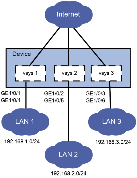
As shown in Figure 2, LAN 1, LAN 2, and LAN 3 use 192.168.1.0/24, 192.168.2.0/24, and 192.168.3.0/24, respectively.
Configure vSystems for the LANs as follows:
· Configure vSystem vsys1 for LAN 1.
· Configure vSystem vsys2 for LAN 2.
· Configure vSystem vsys3 for LAN 3.
Procedure
1. Configure vSystem vsys1 for LAN 1:
# Create a vSystem named vsys1 and configure a description for it.
<Device> system-view
[Device] vsys vsys1
[Device-vsys-2-vsys1] description vsys-1
# Assign GigabitEthernet 1/0/1 and GigabitEthernet 1/0/4 to the vSystem.
[Device-vsys-2-vsys1] allocate interface gigabitethernet 1/0/1
Some configurations on the interface are removed.
[Device-vsys-2-vsys1] allocate interface gigabitethernet 1/0/4
Some configurations on the interface are removed.
[Device-vsys-2-vsys1] quit
# Log in to the vSystem from the default vSystem.
[Device] switchto vsys vsys1
<Device-vsys1> system-view
# Configure Telnet login to enable remote vSystem management. (Details not shown. For more information about Telnet login configuration, see login management in Fundamentals Configuration Guide.)
# Assign IP address 192.168.1.251/24 to GigabitEthernet 1/0/1.
[Device-vsys1] interface gigabitethernet 1/0/1
[Device-vsys1-GigabitEthernet1/0/1] ip address 192.168.1.251 24
# Return to the default vSystem.
[Device-vsys1-GigabitEthernet1/0/1] return
<Device-vsys1> quit
[Device]
2. Configure vSystem vsys2 for LAN 2:
# Create a vSystem named vsys2 and configure a description for it.
[Device] vsys vsys2
[Device-vsys-3-vsys2] description vsys-2
# Assign GigabitEthernet 1/0/2 and GigabitEthernet 1/0/5 to the vSystem.
[Device-vsys-3-vsys2] allocate interface gigabitethernet 1/0/2
Some configurations on the interface are removed.
[Device-vsys-3-vsys2] allocate interface gigabitethernet 1/0/5
Some configurations on the interface are removed.
[Device-vsys-3-vsys2] quit
# Log in to the vSystem from the default vSystem.
[Device] switchto vsys vsys2
<Device-vsys2> system-view
# Configure Telnet login to enable remote vSystem management. (Details not shown. For more information about Telnet login configuration, see login management in Fundamentals Configuration Guide.)
# Assign IP address 192.168.2.251/24 to GigabitEthernet 1/0/2.
[Device-vsys2] interface gigabitethernet 1/0/2
[Device-vsys2-GigabitEthernet1/0/2] ip address 192.168.2.251 24
# Return to the default vSystem.
[Device-vsys2-GigabitEthernet1/0/2] return
<Device-vsys2> quit
[Device]
3. Configure vSystem vsys3 for LAN 3:
# Create a vSystem named vsys3 and configure a description for it.
[Device] vsys vsys3
[Device-vsys-4-vsys3] description vsys-3
# Assign GigabitEthernet 1/0/3 and GigabitEthernet 1/0/6 to the vSystem.
[Device-vsys-4-vsys3] allocate interface gigabitethernet 1/0/3
Some configurations on the interface are removed.
[Device-vsys-4-vsys3] allocate interface gigabitethernet 1/0/6
Some configurations on the interface are removed.
[Device-vsys-4-vsys3] quit
# Log in to the vSystem from the default vSystem.
[Device] switchto vsys vsys3
<Device-vsys2> system-view
# Configure Telnet login to enable remote vSystem management. (Details not shown. For more information about Telnet login configuration, see login management in Fundamentals Configuration Guide.)
# Assign IP address 192.168.3.251/24 to GigabitEthernet 1/0/3.
[Device-vsys3] interface gigabitethernet 1/0/3
[Device-vsys3-GigabitEthernet1/0/3] ip address 192.168.3.251 24
# Return to the default vSystem.
[Device-vsys3-GigabitEthernet1/0/3] return
<Device-vsys3> quit
[Device]
Verifying the configuration
# Verify that the device has four vSystems and all vSystems are in active state.
[Device] display vsys
ID Name Status Description
1 Admin Active Default
2 vsys1 Active vsys-1
3 vsys2 Active vsys-2
4 vsys3 Active vsys-3
Example: Using vSystems for enterprise network isolation (non-default vSystems have public network interfaces)
Network configuration
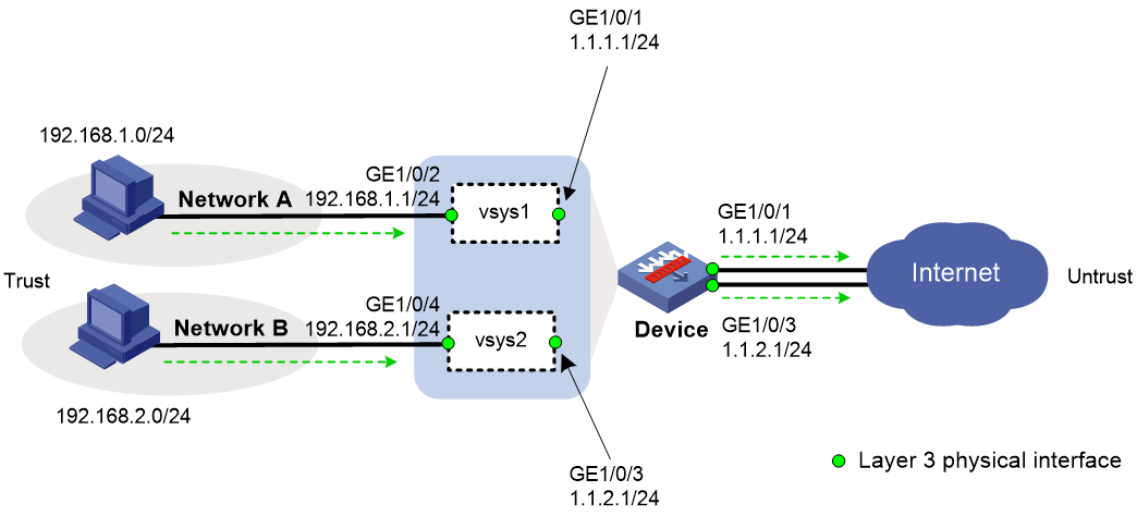
As shown in Figure 3:
· The device acts as a security gateway.
· The internal network is divided into Network A for the R&D department and Network B for non-R&D departments. Users in Network A and Network B are isolated.
· In Network A, only users in subnet 192.168.1.128/25 can use independent public network interfaces to access the Internet. In Network B, all users can use independent public network interfaces to access the Internet.
Configuring vSystem vsys1
1. Create vSystem vsys1 and assign interfaces to the vSystem:
# Create vSystem vsys1 and configure a description for the vSystem.
<Device> system-view
[Device] vsys vsys1
[Device-vsys-2-vsys1] description vsys-1
# Assign interfaces GigabitEthernet 1/0/1 and GigabitEthernet 1/0/2 to vSystem vsys1.
[Device-vsys-2-vsys1] allocate interface gigabitethernet 1/0/1
Some configurations on the interface are removed.
[Device-vsys-2-vsys1] allocate interface gigabitethernet 1/0/2
Some configurations on the interface are removed.
[Device-vsys-2-vsys1] quit
2. Log in to vSystem vsys1, assign IP addresses to interfaces, and add interfaces to security zones:
# Log in to vSystem vsys1.
[Device] switchto vsys vsys1
<Device-vsys1> system-view
# Assign IP addresses to interfaces.
[Device-vsys1] interface gigabitethernet 1/0/1
[Device-vsys1-GigabitEthernet1/0/1] ip address 1.1.1.1 24
[Device-vsys1-GigabitEthernet1/0/1] quit
[Device-vsys1] interface gigabitethernet 1/0/2
[Device-vsys1-GigabitEthernet1/0/2] ip address 192.168.1.1 24
[Device-vsys1-GigabitEthernet1/0/2] quit
# Add interfaces to security zones.
[Device-vsys1] security-zone name trust
[Device-vsys1-security-zone-Trust] import interface gigabitethernet 1/0/2
[Device-vsys1-security-zone-Trust] quit
[Device-vsys1] security-zone name untrust
[Device-vsys1-security-zone-Untrust] import interface gigabitethernet 1/0/1
[Device-vsys1-security-zone-Untrust] quit
3. Configure settings for routing. This example configures a static route. In the route, the next hop IP address is 1.1.1.2 for users in vSystem vsys1 to access the Internet.
[Device-vsys1] ip route-static 0.0.0.0 0 1.1.1.2
4. Configure a rule named trust-untrust in the IPv4 security policy to allow users in subnet 192.168.1.128/25 to access the Internet.
[Device-vsys1] security-policy ip
[Device-vsys1-security-policy-ip] rule name trust-untrust
[Device-vsys1-security-policy-ip-1-trust-untrust] source-zone trust
[Device-vsys1-security-policy-ip-1-trust-untrust] destination-zone untrust
[Device-vsys1-security-policy-ip-1-trust-untrust] source-ip-subnet 192.168.1.128 25
[Device-vsys1-security-policy-ip-1-trust-untrust] action pass
[Device-vsys1-security-policy-ip-1-trust-untrust] quit
[Device-vsys1-security-policy-ip] quit
5. Configure NAT:
# Configure ACL 2000, and create a rule to permit the packets only from 192.168.1.128/25 to be translated.
[Device-vsys1] acl basic 2000
[Device-vsys1-acl-ipv4-basic-2000] rule permit source 192.168.1.128 0.0.0.127
[Device-vsys1-acl-ipv4-basic-2000] quit
# Enable outbound dynamic NAT with Easy IP on interface GigabitEthernet 1/0/1 so that NAT translates the source addresses of the packets matching the ACL and destined for the Internet into the IP address of interface GigabitEthernet 1/0/1.
[Device-vsys1] interface gigabitethernet 1/0/1
[Device-vsys1-GigabitEthernet1/0/1] nat outbound 2000
6. Return to the default vSystem from vSystem vsys1.
[Device-vsys1-GigabitEthernet1/0/1] return
<Device-vsys1> quit
[Device]
Configuring vSystem vsys2
1. Create vSystem vsys2 and assign interfaces to the vSystem:
# Create vSystem vsys2 and configure a description for the vSystem.
[Device] vsys vsys2
[Device-vsys-3-vsys2] description vsys-2
# Assign interfaces GigabitEthernet 1/0/3 and GigabitEthernet 1/0/4 to vSystem vsys2.
[Device-vsys-3-vsys2] allocate interface gigabitethernet 1/0/3
Some configurations on the interface are removed.
[Device-vsys-3-vsys2] allocate interface gigabitethernet 1/0/4
Some configurations on the interface are removed.
[Device-vsys-3-vsys2] quit
2. Log in to vSystem vsys2, assign IP addresses to interfaces, and add interfaces to security zones:
# Log in to vSystem vsys2.
[Device] switchto vsys vsys2
<Device-vsys2> system-view
# Assign IP addresses to interfaces.
[Device-vsys2] interface gigabitethernet 1/0/3
[Device-vsys2-GigabitEthernet1/0/3] ip address 1.1.2.1 24
[Device-vsys2-GigabitEthernet1/0/3] quit
[Device-vsys2] interface gigabitethernet 1/0/4
[Device-vsys2-GigabitEthernet1/0/4] ip address 192.168.2.1 24
[Device-vsys2-GigabitEthernet1/0/4] quit
# Add interfaces to security zones.
[Device-vsys2] security-zone name trust
[Device-vsys2-security-zone-Trust] import interface gigabitethernet 1/0/4
[Device-vsys2-security-zone-Trust] quit
[Device-vsys2] security-zone name untrust
[Device-vsys2-security-zone-Untrust] import interface gigabitethernet 1/0/3
[Device-vsys2-security-zone-Untrust] quit
3. Configure settings for routing. This example configures a static route. In the route, the next hop IP address is 1.1.2.2 for users in vSystem vsys2 to access the Internet.
[Device-vsys2] ip route-static 0.0.0.0 0 1.1.2.2
4. Configure a rule named trust-untrust in the IPv4 security policy to allow users in subnet 192.168.2.0/24 to access the Internet.
[Device-vsys2] security-policy ip
[Device-vsys2-security-policy-ip] rule name trust-untrust
[Device-vsys2-security-policy-ip-1-trust-untrust] source-zone trust
[Device-vsys2-security-policy-ip-1-trust-untrust] destination-zone untrust
[Device-vsys2-security-policy-ip-1-trust-untrust] source-ip-subnet 192.168.2.0 24
[Device-vsys2-security-policy-ip-1-trust-untrust] action pass
[Device-vsys2-security-policy-ip-1-trust-untrust] quit
[Device-vsys2-security-policy-ip] quit
5. Configure NAT:
# Configure ACL 2000, and create a rule to permit the packets only from 192.168.2.0/24 to be translated.
[Device-vsys2] acl basic 2000
[Device-vsys2-acl-ipv4-basic-2000] rule permit source 192.168.2.0 0.0.0.255
[Device-vsys2-acl-ipv4-basic-2000] quit
# Enable outbound dynamic NAT with Easy IP on interface GigabitEthernet 1/0/3 so that NAT translates the source addresses of the packets matching the ACL and destined for the Internet into the IP address of interface GigabitEthernet 1/0/3.
[Device-vsys2] interface gigabitethernet 1/0/3
[Device-vsys2-GigabitEthernet1/0/3] nat outbound 2000
6. Return to the default vSystem from vSystem vsys2.
[Device-vsys2-GigabitEthernet1/0/3] return
<Device-vsys2> quit
[Device]
Verifying the configuration
# Verify that the vSystems are running correctly on the device. The device has three active vSystems.
[Device] display vsys
ID Name Status Description
1 Admin Active Default
2 vsys1 Active vsys-1
3 vsys2 Active vsys-2
# Verify that users in subnet 192.168.1.128/25 can access the Internet.
C:\> ping 3.3.3.3
Pinging 3.3.3.3 with 32 bytes of data:
Reply from 3.3.3.3: bytes=32 time=51ms TTL=255
Reply from 3.3.3.3: bytes=32 time=44ms TTL=255
Reply from 3.3.3.3: bytes=32 time=1ms TTL=255
Reply from 3.3.3.3: bytes=32 time=1ms TTL=255
Ping statistics for 3.3.3.3:
Packets: Sent = 4, Received = 4, Lost = 0 (0% loss),
Approximate round trip times in milli-seconds:
Minimum = 1ms, Maximum = 51ms, Average = 24ms
# Verify that users in subnet 192.168.2.0/24 can access the Internet.
C:\> ping 3.3.3.3
Pinging 3.3.3.3 with 32 bytes of data:
Reply from 3.3.3.3: bytes=32 time=25ms TTL=255
Reply from 3.3.3.3: bytes=32 time=36ms TTL=255
Reply from 3.3.3.3: bytes=32 time=1ms TTL=255
Reply from 3.3.3.3: bytes=32 time=1ms TTL=255
Ping statistics for 3.3.3.3:
Packets: Sent = 4, Received = 4, Lost = 0 (0% loss),
Approximate round trip times in milli-seconds:
Minimum = 1ms, Maximum = 36ms, Average = 16ms
Example: Using vSystems for enterprise network isolation (only the default vSystem has public network interfaces)
Network configuration
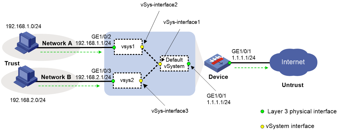
As shown in Figure 4:
· The device acts as a security gateway.
· The internal network is divided into Network A for the R&D department and Network B for non-R&D departments. Users in Network A and Network B are isolated.
· In Network A, only users in subnet 192.168.1.128/25 can access the Internet. In Network B, all users can access the Internet.
Configuring the default vSystem
1. Create vSystems and assign interfaces to the vSystems:
# Create vSystem vsys1 and configure a description for the vSystem.
<Device> system-view
[Device] vsys vsys1
[Device-vsys-2-vsys1] description vsys-1
# Assign interface GigabitEthernet 1/0/2 to vSystem vsys1.
[Device-vsys-2-vsys1] allocate interface gigabitethernet 1/0/2
Some configurations on the interface are removed.
[Device-vsys-2-vsys1] quit
# Create vSystem vsys2 and configure a description for the vSystem.
[Device] vsys vsys2
[Device-vsys-3-vsys2] description vsys-2
# Assign interface GigabitEthernet 1/0/3 to vSystem vsys2.
[Device-vsys-3-vsys2] allocate interface gigabitethernet 1/0/3
Some configurations on the interface are removed.
[Device-vsys-3-vsys2] quit
2. Assign IP addresses to interfaces and add interfaces to security zones:
# Assign IP addresses to interfaces.
[Device] interface gigabitethernet 1/0/1
[Device-GigabitEthernet1/0/1] ip address 1.1.1.1 24
[Device-GigabitEthernet1/0/1] quit
# Add interfaces to security zones.
[Device] security-zone name trust
[Device-security-zone-Trust] import interface vsys-interface 1
[Device-security-zone-Trust] quit
[Device] security-zone name untrust
[Device-security-zone-Untrust] import interface gigabitethernet 1/0/1
[Device-security-zone-Untrust] quit
3. Configure settings for routing. This example configures static routes. In a route, the next hop IP address is 1.1.1.2 for internal users to access the Internet through the default vSystem.
[Device] ip route-static 0.0.0.0 0 1.1.1.2
[Device] ip route-static 192.168.1.0 24 vpn-instance vsys1
[Device] ip route-static 192.168.2.0 24 vpn-instance vsys2
4. Configure a rule named trust-untrust in the IPv4 security policy to allow internal users to access the Internet.
[Device] security-policy ip
[Device-security-policy-ip] rule name trust-untrust
[Device-security-policy-ip-1-trust-untrust] source-zone trust
[Device-security-policy-ip-1-trust-untrust] destination-zone untrust
[Device-security-policy-ip-1-trust-untrust] source-ip-subnet 192.168.1.128 25
[Device-security-policy-ip-1-trust-untrust] source-ip-subnet 192.168.2.0 24
[Device-security-policy-ip-1-trust-untrust] action pass
[Device-security-policy-ip-1-trust-untrust] quit
[Device-security-policy-ip] quit
5. Configure NAT:
# Configure ACL 2000, and create a rule to permit the packets only from 192.168.1.128/25 and 192.168.2.0/24 to be translated.
[Device] acl basic 2000
[Device-acl-ipv4-basic-2000] rule permit source 192.168.1.128 0.0.0.127
[Device-acl-ipv4-basic-2000] rule permit source 192.168.2.0 0.0.0.255
[Device-acl-ipv4-basic-2000] quit
# Enable outbound dynamic NAT with Easy IP on interface GigabitEthernet 1/0/1 so that NAT translates the source addresses of the packets matching the ACL and destined for the Internet into the IP address of interface GigabitEthernet 1/0/1.
[Device] interface gigabitethernet 1/0/1
[Device-GigabitEthernet1/0/1] nat outbound 2000
[Device-GigabitEthernet1/0/1] quit
Configuring vSystem vsys1
1. Log in to vSystem vsys1, assign IP addresses to interfaces, and add interfaces to security zones:
# Log in to vSystem vsys1.
[Device] switchto vsys vsys1
<Device-vsys1> system-view
# Assign IP addresses to interfaces.
[Device-vsys1] interface gigabitethernet 1/0/2
[Device-vsys1-GigabitEthernet1/0/2] ip address 192.168.1.1 24
[Device-vsys1-GigabitEthernet1/0/2] quit
# Add interfaces to security zones.
[Device-vsys1] security-zone name trust
[Device-vsys1-security-zone-Trust] import interface gigabitethernet 1/0/2
[Device-vsys1-security-zone-Trust] quit
[Device-vsys1] security-zone name untrust
[Device-vsys1-security-zone-Untrust] import interface vsys-interface 2
[Device-vsys1-security-zone-Untrust] quit
2. Configure settings for routing. This example configures a static route. In the route, the next hop is the default vSystem for users in vSystem vsys1 to access the Internet.
[Device-vsys1] ip route-static 0.0.0.0 0 public
3. Configure a rule named trust-untrust in the IPv4 security policy to allow users in subnet 192.168.1.128/25 to access the Internet.
[Device-vsys1] security-policy ip
[Device-vsys1-security-policy-ip] rule name trust-untrust
[Device-vsys1-security-policy-ip-1-trust-untrust] source-zone trust
[Device-vsys1-security-policy-ip-1-trust-untrust] destination-zone untrust
[Device-vsys1-security-policy-ip-1-trust-untrust] source-ip-subnet 192.168.1.128 25
[Device-vsys1-security-policy-ip-1-trust-untrust] action pass
4. Return to the default vSystem from vSystem vsys1.
[Device-vsys1-security-policy-ip-1-trust-untrust] return
<Device-vsys1> quit
[Device]
Configuring vSystem vsys2
1. Log in to vSystem vsys2, assign IP addresses to interfaces, and add interfaces to security zones:
# Log in to vSystem vsys2.
[Device] switchto vsys vsys2
<Device-vsys2> system-view
# Assign IP addresses to interfaces.
[Device-vsys2] interface gigabitethernet 1/0/3
[Device-vsys2-GigabitEthernet1/0/3] ip address 192.168.2.1 24
[Device-vsys2-GigabitEthernet1/0/3] quit
# Add interfaces to security zones.
[Device-vsys2] security-zone name trust
[Device-vsys2-security-zone-Trust] import interface gigabitethernet 1/0/3
[Device-vsys2-security-zone-Trust] quit
[Device-vsys2] security-zone name untrust
[Device-vsys2-security-zone-Untrust] import interface vsys-interface 3
[Device-vsys2-security-zone-Untrust] quit
2. Configure settings for routing. This example configures a static route. In the route, the next hop is the default vSystem for users in vSystem vsys2 to access the Internet.
[Device-vsys2] ip route-static 0.0.0.0 0 public
3. Configure a rule named trust-untrust in the IPv4 security policy to allow users in subnet 192.168.2.0/24 to access the Internet.
[Device-vsys2] security-policy ip
[Device-vsys2-security-policy-ip] rule name trust-untrust
[Device-vsys2-security-policy-ip-1-trust-untrust] source-zone trust
[Device-vsys2-security-policy-ip-1-trust-untrust] destination-zone untrust
[Device-vsys2-security-policy-ip-1-trust-untrust] source-ip-subnet 192.168.2.0 24
[Device-vsys2-security-policy-ip-1-trust-untrust] action pass
4. Return to the default vSystem from vSystem vsys2.
[Device-vsys2-security-policy-ip-1-trust-untrust] return
<Device-vsys2> quit
[Device]
Verifying the configuration
# Verify that the vSystems are running correctly on the device. The device has three active vSystems.
[Device] display vsys
ID Name Status Description
1 Admin Active Default
2 vsys1 Active vsys-1
3 vsys2 Active vsys-2
# Verify that users in subnet 192.168.1.128/25 can access the Internet.
C:\> ping 3.3.3.3
Pinging 3.3.3.3 with 32 bytes of data:
Reply from 3.3.3.3: bytes=32 time=51ms TTL=255
Reply from 3.3.3.3: bytes=32 time=44ms TTL=255
Reply from 3.3.3.3: bytes=32 time=1ms TTL=255
Reply from 3.3.3.3: bytes=32 time=1ms TTL=255
Ping statistics for 3.3.3.3:
Packets: Sent = 4, Received = 4, Lost = 0 (0% loss),
Approximate round trip times in milli-seconds:
Minimum = 1ms, Maximum = 51ms, Average = 24ms
# Verify that users in subnet 192.168.2.0/24 can access the Internet.
C:\> ping 3.3.3.3
Pinging 3.3.3.3 with 32 bytes of data:
Reply from 3.3.3.3: bytes=32 time=25ms TTL=255
Reply from 3.3.3.3: bytes=32 time=36ms TTL=255
Reply from 3.3.3.3: bytes=32 time=1ms TTL=255
Reply from 3.3.3.3: bytes=32 time=1ms TTL=255
Ping statistics for 3.3.3.3:
Packets: Sent = 4, Received = 4, Lost = 0 (0% loss),
Approximate round trip times in milli-seconds:
Minimum = 1ms, Maximum = 36ms, Average = 16ms
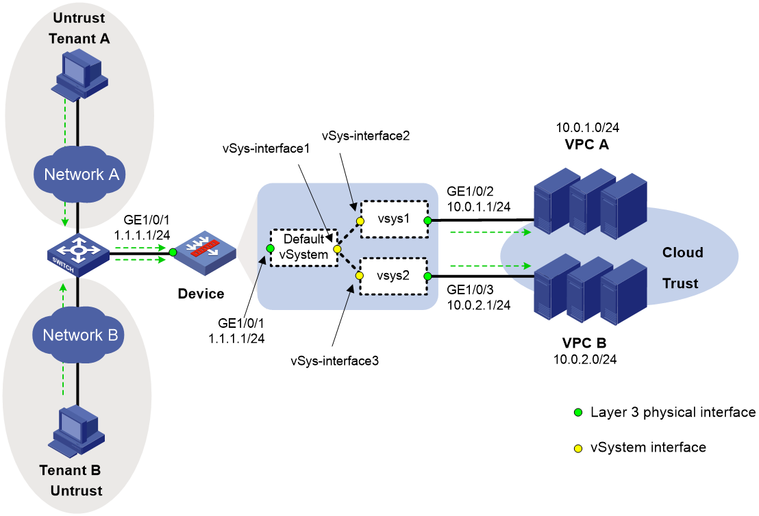
Example: Using vSystems as cloud gateways
Network configuration
As shown in Figure 5:
· The device acts as a security gateway to provide customized security services for tenants.
· Tenant A uses public IP 1.1.1.2 to access its own Web server and Tenant B uses public IP 1.1.1.3 to access its own Web server.
· Because Tenant A and Tenant B have different service traffic volume, assign different amount of system resources to the tenants on the device.
Configuring the default vSystem
1. Create vSystems and assign interfaces to the vSystems:
# Create vSystem vsys1 and configure a description for the vSystem.
<Device> system-view
[Device] vsys vsys1
[Device-vsys-2-vsys1] description vsys-1
# Assign interface GigabitEthernet 1/0/2 to vSystem vsys1.
[Device-vsys-2-vsys1] allocate interface gigabitethernet 1/0/2
Some configurations on the interface are removed.
[Device-vsys-2-vsys1] quit
# Create vSystem vsys2 and configure a description for the vSystem.
[Device] vsys vsys2
[Device-vsys-3-vsys2] description vsys-2
# Assign interface GigabitEthernet 1/0/3 to vSystem vsys2.
[Device-vsys-3-vsys2] allocate interface gigabitethernet 1/0/3
Some configurations on the interface are removed.
[Device-vsys-3-vsys2] quit
2. Assign IP addresses to interfaces and add interfaces to security zones:
# Assign IP addresses to interfaces.
[Device] interface gigabitethernet 1/0/1
[Device-GigabitEthernet1/0/1] ip address 1.1.1.1 24
[Device-GigabitEthernet1/0/1] quit
# Add interfaces to security zones.
[Device] security-zone name trust
[Device-security-zone-Trust] import interface vsys-interface 1
[Device-security-zone-Trust] quit
[Device] security-zone name untrust
[Device-security-zone-Untrust] import interface gigabitethernet 1/0/1
[Device-security-zone-Untrust] quit
3. Configure settings for routing:
This example configures static routes.
# Configure a static route for internal users to access the Internet through the default vSystem. In the route, the next hop IP address is 1.1.1.2.
[Device] ip route-static 0.0.0.0 0 1.1.1.2
# Configure a static route to redistribute the traffic from external users to VPC A to vSystem vsys1.
[Device] ip route-static 10.0.1.0 24 vpn-instance vsys1
# Configure a static route to redistribute the traffic from external users to VPC B to vSystem vsys2.
[Device] ip route-static 10.0.2.0 24 vpn-instance vsys2
4. Configure a rule named untrust-trust in the IPv4 security policy to allow external users to access internal servers.
[Device] security-policy ip
[Device-security-policy-ip] rule name untrust-trust
[Device-security-policy-ip-1-untrust-trust] source-zone untrust
[Device-security-policy-ip-1-untrust-trust] destination-zone trust
[Device-security-policy-ip-1-untrust-trust] destination-ip-subnet 10.0.1.0 24
[Device-security-policy-ip-1-untrust-trust] destination-ip-subnet 10.0.2.0 24
[Device-security-policy-ip-1-untrust-trust] action pass
[Device-security-policy-ip-1-untrust-trust] quit
[Device-security-policy-ip] quit
5. Configure a NAT internal server:
# Configure the NAT internal server to allow external users to use IP address 1.1.1.2 and port number 8080 to access the server at 10.0.1.2 (internal IP address).
[Device] interface gigabitethernet 1/0/1
[Device-GigabitEthernet1/0/1] nat server protocol tcp global 1.1.1.2 8080 inside 10.0.1.2 http
# Configure the NAT internal server to allow external users to use IP address 1.1.1.3 and port number 8080 to access the server at 10.0.2.2 (internal IP address).
[Device-GigabitEthernet1/0/1] nat server protocol tcp global 1.1.1.3 8080 inside 10.0.2.2 http
[Device-GigabitEthernet1/0/1] quit
Configuring vSystem vsys1
1. Log in to vSystem vsys1, assign IP addresses to interfaces, and add interfaces to security zones:
# Log in to vSystem vsys1.
[Device] switchto vsys vsys1
<Device-vsys1> system-view
# Assign IP addresses to interfaces.
[Device-vsys1] interface gigabitethernet 1/0/2
[Device-vsys1-GigabitEthernet1/0/2] ip address 10.0.1.1 24
[Device-vsys1-GigabitEthernet1/0/2] quit
# Add interfaces to security zones.
[Device-vsys1] security-zone name trust
[Device-vsys1-security-zone-Trust] import interface gigabitethernet 1/0/2
[Device-vsys1-security-zone-Trust] quit
[Device-vsys1] security-zone name untrust
[Device-vsys1-security-zone-Untrust] import interface vsys-interface 2
[Device-vsys1-security-zone-Untrust] quit
2. Configure settings for routing. This example configures a static route. In the route, the next hop is the default vSystem for users in vSystem vsys1 to access the Internet.
[Device-vsys1] ip route-static 0.0.0.0 0 public
3. Configure a rule named untrust-trust in the IPv4 security policy to allow external users to access VPC A.
[Device-vsys1] security-policy ip
[Device-vsys1-security-policy-ip] rule name untrust-trust
[Device-vsys1-security-policy-ip-1-untrust-trust] source-zone untrust
[Device-vsys1-security-policy-ip-1-untrust-trust] destination-zone trust
[Device-vsys1-security-policy-ip-1-untrust-trust] destination-ip-subnet 10.0.1.0 24
[Device-vsys1-security-policy-ip-1-untrust-trust] action pass
4. Return to the default vSystem from vSystem vsys1.
[Device-vsys1-security-policy-ip-1-untrust-trust] return
<Device-vsys1> quit
[Device]
Configuring vSystem vsys2
1. Log in to vSystem vsys2, assign IP addresses to interfaces, and add interfaces to security zones:
# Log in to vSystem vsys2.
[Device] switchto vsys vsys2
<Device-vsys2> system-view
# Assign IP addresses to interfaces.
[Device-vsys2] interface gigabitethernet 1/0/3
[Device-vsys2-GigabitEthernet1/0/3] ip address 10.0.2.1 24
[Device-vsys2-GigabitEthernet1/0/3] quit
# Add interfaces to security zones.
[Device-vsys2] security-zone name trust
[Device-vsys2-security-zone-Trust] import interface gigabitethernet 1/0/3
[Device-vsys2-security-zone-Trust] quit
[Device-vsys2] security-zone name untrust
[Device-vsys2-security-zone-Untrust] import interface vsys-interface 3
[Device-vsys2-security-zone-Untrust] quit
2. Configure settings for routing. This example configures a static route. In the route, the next hop is the default vSystem for users in vSystem vsys2 to access the Internet.
[Device-vsys2] ip route-static 0.0.0.0 0 public
3. Configure a rule named untrust-trust in the IPv4 security policy to allow external users to access VPC B.
[Device-vsys2] security-policy ip
[Device-vsys2-security-policy-ip] rule name untrust-trust
[Device-vsys2-security-policy-ip-1-untrust-trust] source-zone untrust
[Device-vsys2-security-policy-ip-1-untrust-trust] destination-zone trust
[Device-vsys2-security-policy-ip-1-untrust-trust] destination-ip-subnet 10.0.2.0 24
[Device-vsys2-security-policy-ip-1-untrust-trust] action pass
4. Return to the default vSystem from vSystem vsys2.
[Device-vsys2-security-policy-ip-1-untrust-trust] return
<Device-vsys2> quit
[Device]
Verifying the configuration
# Verify that the vSystems are running correctly on the device. The device has three active vSystems.
[Device] display vsys
ID Name Status Description
1 Admin Active Default
2 vsys1 Active vsys-1
3 vsys2 Active vsys-2
# Verify that Tenant A can use URL http://1.1.1.2:8080 to access the server at 10.0.1.2 in VPC A.
# Verify that Tenant B can use URL http://1.1.1.3:8080 to access the server at 10.0.2.2 in VPC B.
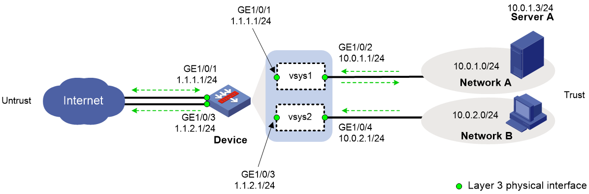
Example: Configuring Internet users to use public network interfaces in non-default vSystems to access internal servers
Network configuration
As shown in Figure 6:
· The device acts as a security gateway.
· The internal network is divided into Network A and Network B. Users in Network A and Network B are isolated.
· Users in Network A and Network B can use independent public network interfaces to access the Internet.
· Users in the Internet can use public IP 1.1.1.2 to access the Web interface of Server A in Network A.
Configuring vSystem vsys1
1. Create vSystem vsys1 and assign interfaces to the vSystems:
# Create vSystem vsys1 and configure a description for the vSystem.
<Device> system-view
[Device] vsys vsys1
[Device-vsys-2-vsys1] description vsys-1
# Assign interfaces GigabitEthernet 1/0/1 and GigabitEthernet 1/0/2 to vSystem vsys1.
[Device-vsys-2-vsys1] allocate interface gigabitethernet 1/0/1
Some configurations on the interface are removed.
[Device-vsys-2-vsys1] allocate interface gigabitethernet 1/0/2
Some configurations on the interface are removed.
[Device-vsys-2-vsys1] quit
2. Log in to vSystem vsys1, assign IP addresses to interfaces, and add interfaces to security zones:
# Log in to vSystem vsys1.
[Device] switchto vsys vsys1
<Device-vsys1> system-view
# Assign IP addresses to interfaces.
[Device-vsys1] interface gigabitethernet 1/0/1
[Device-vsys1-GigabitEthernet1/0/1] ip address 1.1.1.1 24
[Device-vsys1-GigabitEthernet1/0/1] quit
[Device-vsys1] interface gigabitethernet 1/0/2
[Device-vsys1-GigabitEthernet1/0/2] ip address 10.0.1.1 24
[Device-vsys1-GigabitEthernet1/0/2] quit
# Add interfaces to security zones.
[Device-vsys1] security-zone name trust
[Device-vsys1-security-zone-Trust] import interface gigabitethernet 1/0/2
[Device-vsys1-security-zone-Trust] quit
[Device-vsys1] security-zone name untrust
[Device-vsys1-security-zone-Untrust] import interface gigabitethernet 1/0/1
[Device-vsys1-security-zone-Untrust] quit
3. Configure settings for routing. This example configures a static route. In the route, the next hop IP address is 1.1.1.2 for users in vSystem vsys1 to access the Internet.
[Device-vsys1] ip route-static 0.0.0.0 0 1.1.1.2
4. Configure the IPv4 security policy:
# Configure a rule named trust-untrust to allow internal users to access the Internet.
[Device-vsys1] security-policy ip
[Device-vsys1-security-policy-ip] rule name trust-untrust
[Device-vsys1-security-policy-ip-1-trust-untrust] source-zone trust
[Device-vsys1-security-policy-ip-1-trust-untrust] destination-zone untrust
[Device-vsys1-security-policy-ip-1-trust-untrust] source-ip-subnet 10.0.1.0 24
[Device-vsys1-security-policy-ip-1-trust-untrust] action pass
[Device-vsys1-security-policy-ip-1-trust-untrust] quit
# Configure a rule named untrust-trust to allow external users to access Server A.
[Device-vsys1-security-policy-ip] rule name untrust-trust
[Device-vsys1-security-policy-ip-2-untrust-trust] source-zone untrust
[Device-vsys1-security-policy-ip-2-untrust-trust] destination-zone trust
[Device-vsys1-security-policy-ip-2-untrust-trust] destination-ip-host 10.0.1.3
[Device-vsys1-security-policy-ip-2-untrust-trust] action pass
[Device-vsys1-security-policy-ip-2-untrust-trust] quit
[Device-vsys1-security-policy-ip] quit
5. Configure NAT:
# Create address group 1 that contains public address 1.1.1.100.
[Device-vsys1] nat address-group 1
[Device-vsys1-address-group-1] address 1.1.1.100 1.1.1.100
[Device-vsys1-address-group-1] quit
# Configure ACL 2000, and create a rule to permit the packets only from Network A to be translated.
[Device-vsys1] acl basic 2000
[Device-vsys1-acl-ipv4-basic-2000] rule permit source 10.0.1.0 0.0.0.255
[Device-vsys1-acl-ipv4-basic-2000] quit
# Configure an outbound NAT rule to allow users in Network A to use addresses in address group 1 to access the Internet.
[Device-vsys1] interface gigabitethernet 1/0/1
[Device-vsys1-GigabitEthernet1/0/1] nat outbound 2000 address-group 1
# Configure a NAT internal server to allow external users to use IP address 1.1.1.2 and port number 8080 to access Server A.
[Device-vsys1-GigabitEthernet1/0/1] nat server protocol tcp global 1.1.1.2 8080 inside 10.0.1.3 http
6. Return to the default vSystem from vSystem vsys1.
[Device-vsys1-GigabitEthernet1/0/1] return
<Device-vsys1> quit
[Device]
Configuring vSystem vsys2
1. Create vSystem vsys2 and assign interfaces to the vSystem:
# Create vSystem vsys2 and configure a description for the vSystem.
<Device> system-view
[Device] vsys vsys2
[Device-vsys-3-vsys2] description vsys-2
# Assign interfaces GigabitEthernet 1/0/3 and GigabitEthernet 1/0/4 to vSystem vsys2.
[Device-vsys-3-vsys2] allocate interface gigabitethernet 1/0/3
Some configurations on the interface are removed.
[Device-vsys-3-vsys2] allocate interface gigabitethernet 1/0/4
Some configurations on the interface are removed.
[Device-vsys-3-vsys2] quit
2. Log in to vSystem vsys2, assign IP addresses to interfaces, and add interfaces to security zones:
# Log in to vSystem vsys2.
[Device] switchto vsys vsys2
<Device-vsys2> system-view
# Assign IP addresses to interfaces.
[Device-vsys2] interface gigabitethernet 1/0/3
[Device-vsys2-GigabitEthernet1/0/3] ip address 1.1.2.1 24
[Device-vsys2-GigabitEthernet1/0/3] quit
[Device-vsys2] interface gigabitethernet 1/0/4
[Device-vsys2-GigabitEthernet1/0/4] ip address 10.0.2.1 24
[Device-vsys2-GigabitEthernet1/0/4] quit
# Add interfaces to security zones.
[Device-vsys2] security-zone name trust
[Device-vsys2-security-zone-Trust] import interface gigabitethernet 1/0/4
[Device-vsys2-security-zone-Trust] quit
[Device-vsys2] security-zone name untrust
[Device-vsys2-security-zone-Untrust] import interface gigabitethernet 1/0/3
[Device-vsys2-security-zone-Untrust] quit
3. Configure settings for routing. This example configures a static route. In the route, the next hop IP address is 1.1.2.2 for users in vSystem vsys2 to access the Internet.
[Device-vsys2] ip route-static 0.0.0.0 0 1.1.2.2
4. Configure a rule named trust-untrust in the IPv4 security policy to allow internal users to access the Internet.
[Device-vsys2] security-policy ip
[Device-vsys2-security-policy-ip] rule name trust-untrust
[Device-vsys2-security-policy-ip-1-trust-untrust] source-zone trust
[Device-vsys2-security-policy-ip-1-trust-untrust] destination-zone untrust
[Device-vsys2-security-policy-ip-1-trust-untrust] source-ip-subnet 10.0.2.0 24
[Device-vsys2-security-policy-ip-1-trust-untrust] action pass
[Device-vsys2-security-policy-ip-1-trust-untrust] quit
5. Configure NAT:
# Create address group 1 that contains public address 1.1.1.101.
[Device-vsys2] nat address-group 1
[Device-vsys2-address-group-1] address 1.1.1.100 1.1.1.101
[Device-vsys2-address-group-1] quit
# Configure ACL 2000, and create a rule to permit the packets only from Network B to be translated.
[Device-vsys2] acl basic 2000
[Device-vsys2-acl-ipv4-basic-2000] rule permit source 10.0.2.0 0.0.0.255
[Device-vsys2-acl-ipv4-basic-2000] quit
# Configure an outbound NAT rule to allow users in Network B to use addresses in address group 1 to access the Internet.
[Device-vsys2] interface gigabitethernet 1/0/3
[Device-vsys2-GigabitEthernet1/0/3] nat outbound 2000 address-group 1
6. Return to the default vSystem from vSystem vsys2.
[Device-vsys2-GigabitEthernet1/0/3] return
<Device-vsys2> quit
[Device]
Verifying the configuration
# Verify that the vSystems are running correctly on the device. The device has three active vSystems.
[Device] display vsys
ID Name Status Description
1 Admin Active Default
2 vsys1 Active vsys-1
3 vsys2 Active vsys-2
# Verify that users in the Internet can use URL http://1.1.1.2:8080 to access Server A.
# Verify that users in Network A can access the Internet.
C:\> ping 3.3.3.3
Pinging 3.3.3.3 with 32 bytes of data:
Reply from 3.3.3.3: bytes=32 time=51ms TTL=255
Reply from 3.3.3.3: bytes=32 time=44ms TTL=255
Reply from 3.3.3.3: bytes=32 time=1ms TTL=255
Reply from 3.3.3.3: bytes=32 time=1ms TTL=255
Ping statistics for 3.3.3.3:
Packets: Sent = 4, Received = 4, Lost = 0 (0% loss),
Approximate round trip times in milli-seconds:
Minimum = 1ms, Maximum = 51ms, Average = 24ms
# Verify that users in Network B can access the Internet.
C:\> ping 3.3.3.3
Pinging 3.3.3.3 with 32 bytes of data:
Reply from 3.3.3.3: bytes=32 time=25ms TTL=255
Reply from 3.3.3.3: bytes=32 time=36ms TTL=255
Reply from 3.3.3.3: bytes=32 time=1ms TTL=255
Reply from 3.3.3.3: bytes=32 time=1ms TTL=255
Ping statistics for 3.3.3.3:
Packets: Sent = 4, Received = 4, Lost = 0 (0% loss),
Approximate round trip times in milli-seconds:
Minimum = 1ms, Maximum = 36ms, Average = 16ms
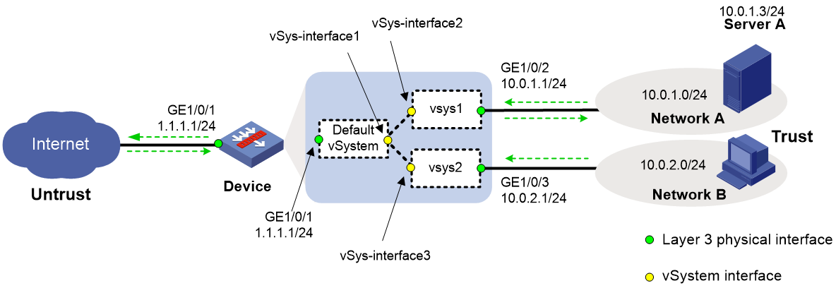
Example: Configuring Internet users to use public network interfaces in the default vSystem to access internal servers
Network configuration
As shown in Figure 7:
· The device acts as a security gateway.
· The internal network is divided into Network A and Network B. Users in Network A and Network B are isolated.
· Network A and Network B are attached to the Internet through a public network interface on the device. Users in Network A use public address 1.1.1.100 and users in Network B use public address 1.1.1.101.
· Users in the Internet can use public IP 1.1.1.2 to access the Web interface of Server A in Network A.
Configuring the default vSystem
1. Create vSystems and assign interfaces to the vSystems:
# Create vSystem vsys1 and configure a description for the vSystem.
<Device> system-view
[Device] vsys vsys1
[Device-vsys-2-vsys1] description vsys-1
# Assign interface GigabitEthernet 1/0/2 to vSystem vsys1.
[Device-vsys-2-vsys1] allocate interface gigabitethernet 1/0/2
Some configurations on the interface are removed.
[Device-vsys-2-vsys1] quit
# Create vSystem vsys2 and configure a description for the vSystem.
[Device] vsys vsys2
[Device-vsys-3-vsys2] description vsys-2
# Assign interface GigabitEthernet 1/0/3 to vSystem vsys2.
[Device-vsys-3-vsys2] allocate interface gigabitethernet 1/0/3
Some configurations on the interface are removed.
[Device-vsys-3-vsys2] quit
2. Assign IP addresses to interfaces and add interfaces to security zones:
# Assign IP addresses to interfaces.
[Device] interface gigabitethernet 1/0/1
[Device-GigabitEthernet1/0/1] ip address 1.1.1.1 24
[Device-GigabitEthernet1/0/1] quit
# Add interfaces to security zones.
[Device] security-zone name trust
[Device-security-zone-Trust] import interface vsys-interface 1
[Device-security-zone-Trust] quit
[Device] security-zone name untrust
[Device-security-zone-Untrust] import interface gigabitethernet 1/0/1
[Device-security-zone-Untrust] quit
3. Configure settings for routing:
This example configures static routes.
# Configure a static route for internal users to access the Internet through the default vSystem. In the route, the next hop IP address is 1.1.1.2.
[Device] ip route-static 0.0.0.0 0 1.1.1.2
# Configure a static route to redistribute the traffic from external users to VPC A to vSystem vsys1.
[Device] ip route-static 10.0.1.0 24 vpn-instance vsys1
# Configure a static route to redistribute the traffic from external users to VPC B to vSystem vsys2.
[Device] ip route-static 10.0.2.0 24 vpn-instance vsys2
4. Configure the IPv4 security policy:
# Configure a rule named untrust-trust to allow external users to access Server A.
[Device] security-policy ip
[Device-security-policy-ip] rule name untrust-trust
[Device-security-policy-ip-1-untrust-trust] source-zone untrust
[Device-security-policy-ip-1-untrust-trust] destination-zone trust
[Device-security-policy-ip-1-untrust-trust] destination-ip-host 10.0.1.3
[Device-security-policy-ip-1-untrust-trust] action pass
[Device-security-policy-ip-1-untrust-trust] quit
# Configure a rule named trust-untrust to allow internal users to access the Internet.
[Device-security-policy-ip] rule name trust-untrust
[Device-security-policy-ip-2-trust-untrust] source-zone trust
[Device-security-policy-ip-2-trust-untrust] destination-zone untrust
[Device-security-policy-ip-2-trust-untrust] source-ip-subnet 10.0.1.0 24
[Device-security-policy-ip-2-trust-untrust] source-ip-subnet 10.0.2.0 24
[Device-security-policy-ip-2-trust-untrust] action pass
[Device-security-policy-ip-2-trust-untrust] quit
[Device-security-policy-ip] quit
5. Configure NAT:
# Create address group 1 that contains public address 1.1.1.100, and create address group 2 that contains public address 1.1.1.101.
[Device] nat address-group 1
[Device-address-group-1] address 1.1.1.100 1.1.1.100
[Device-address-group-1] quit
[Device] nat address-group 2
[Device-address-group-2] address 1.1.1.101 1.1.1.101
[Device-address-group-2] quit
# Configure ACL 2000, and create a rule to permit the packets only from Network A to be translated. Configure ACL 2001, and create a rule to permit the packets only from Network B to be translated.
[Device] acl basic 2000
[Device-acl-ipv4-basic-2000] rule permit source 10.0.1.0 0.0.0.255
[Device-acl-ipv4-basic-2000] quit
[Device] acl basic 2001
[Device-acl-ipv4-basic-2001] rule permit source 10.0.2.0 0.0.0.255
[Device-acl-ipv4-basic-2001] quit
# Configure an outbound NAT rule to allow users in Network A to use addresses in address group 1 to access the Internet. Configure an outbound NAT rule to allow users in Network B to use addresses in address group 2 to access the Internet.
[Device] interface gigabitethernet 1/0/1
[Device-GigabitEthernet1/0/1] nat outbound 2000 address-group 1
[Device-GigabitEthernet1/0/1] nat outbound 2001 address-group 2
# Configure a NAT internal server to allow external users to use IP address 1.1.1.2 and port number 8080 to access Server A.
[Device-GigabitEthernet1/0/1] nat server protocol tcp global 1.1.1.2 8080 inside 10.0.1.3 http
[Device-GigabitEthernet1/0/1] quit
Configuring vSystem vsys1
1. Log in to vSystem vsys1, assign IP addresses to interfaces, and add interfaces to security zones:
# Log in to vSystem vsys1.
[Device] switchto vsys vsys1
<Device-vsys1> system-view
# Assign IP addresses to interfaces.
[Device-vsys1] interface gigabitethernet 1/0/2
[Device-vsys1-GigabitEthernet1/0/2] ip address 10.0.1.1 24
[Device-vsys1-GigabitEthernet1/0/2] quit
# Add interfaces to security zones.
[Device-vsys1] security-zone name trust
[Device-vsys1-security-zone-Trust] import interface gigabitethernet 1/0/2
[Device-vsys1-security-zone-Trust] quit
[Device-vsys1] security-zone name untrust
[Device-vsys1-security-zone-Untrust] import interface vsys-interface 2
[Device-vsys1-security-zone-Untrust] quit
2. Configure settings for routing. This example configures a static route. In the route, the next hop is the default vSystem for users in vSystem vsys1 to access the Internet.
[Device-vsys1] ip route-static 0.0.0.0 0 public
3. Configure the IPv4 security policy:
# Configure a rule named untrust-trust to allow external users to access Server A.
[Device-vsys1] security-policy ip
[Device-vsys1-security-policy-ip] rule name untrust-trust
[Device-vsys1-security-policy-ip-1-untrust-trust] source-zone untrust
[Device-vsys1-security-policy-ip-1-untrust-trust] destination-zone trust
[Device-vsys1-security-policy-ip-1-untrust-trust] destination-ip-host 10.0.1.3
[Device-vsys1-security-policy-ip-1-untrust-trust] action pass
[Device-vsys1-security-policy-ip-1-untrust-trust] quit
# Configure a rule named trust-untrust to allow internal users to access the Internet.
[Device-vsys1-security-policy-ip] rule name trust-untrust
[Device-vsys1-security-policy-ip-2-trust-untrust] source-zone trust
[Device-vsys1-security-policy-ip-2-trust-untrust] destination-zone untrust
[Device-vsys1-security-policy-ip-2-trust-untrust] source-ip-subnet 10.0.1.0 24
[Device-vsys1-security-policy-ip-2-trust-untrust] action pass
4. Return to the default vSystem from vSystem vsys1.
[Device-vsys1-security-policy-ip-2-trust-untrust] return
<Device-vsys1> quit
[Device]
Configuring vSystem vsys2
1. Log in to vSystem vsys2, assign IP addresses to interfaces, and add interfaces to security zones:
# Log in to vSystem vsys2.
[Device] switchto vsys vsys2
<Device-vsys2> system-view
# Assign IP addresses to interfaces.
[Device-vsys2] interface gigabitethernet 1/0/3
[Device-vsys2-GigabitEthernet1/0/3] ip address 10.0.2.1 24
[Device-vsys2-GigabitEthernet1/0/3] quit
# Add interfaces to security zones.
[Device-vsys2] security-zone name trust
[Device-vsys2-security-zone-Trust] import interface gigabitethernet 1/0/3
[Device-vsys2-security-zone-Trust] quit
[Device-vsys2] security-zone name untrust
[Device-vsys2-security-zone-Untrust] import interface vsys-interface 3
[Device-vsys2-security-zone-Untrust] quit
2. Configure settings for routing. This example configures a static route. In the route, the next hop is the default vSystem for users in vSystem vsys2 to access the Internet.
[Device-vsys2] ip route-static 0.0.0.0 0 public
3. Configure a rule named trust-untrust in the IPv4 security policy to allow internal users to access the Internet.
[Device-vsys2] security-policy ip
[Device-vsys2-security-policy-ip] rule name trust-untrust
[Device-vsys2-security-policy-ip-1-trust-untrust] source-zone trust
[Device-vsys2-security-policy-ip-1-trust-untrust] destination-zone untrust
[Device-vsys2-security-policy-ip-1-trust-untrust] source-ip-subnet 10.0.2.0 24
[Device-vsys2-security-policy-ip-1-trust-untrust] action pass
4. Return to the default vSystem from vSystem vsys2.
[Device-vsys2-security-policy-ip-1-trust-untrust] return
<Device-vsys2> quit
[Device]
Verifying the configuration
# Verify that the vSystems are running correctly on the device. The device has three active vSystems.
[Device] display vsys
ID Name Status Description
1 Admin Active Default
2 vsys1 Active vsys-1
3 vsys2 Active vsys-2
# Verify that users in the Internet can use URL http://1.1.1.2:8080 to access Server A.
# Verify that users in Network A can access the Internet.
C:\> ping 3.3.3.3
Pinging 3.3.3.3 with 32 bytes of data:
Reply from 3.3.3.3: bytes=32 time=51ms TTL=255
Reply from 3.3.3.3: bytes=32 time=44ms TTL=255
Reply from 3.3.3.3: bytes=32 time=1ms TTL=255
Reply from 3.3.3.3: bytes=32 time=1ms TTL=255
Ping statistics for 3.3.3.3:
Packets: Sent = 4, Received = 4, Lost = 0 (0% loss),
Approximate round trip times in milli-seconds:
Minimum = 1ms, Maximum = 51ms, Average = 24ms
# Verify that users in Network B can access the Internet.
C:\> ping 3.3.3.3
Pinging 3.3.3.3 with 32 bytes of data:
Reply from 3.3.3.3: bytes=32 time=25ms TTL=255
Reply from 3.3.3.3: bytes=32 time=36ms TTL=255
Reply from 3.3.3.3: bytes=32 time=1ms TTL=255
Reply from 3.3.3.3: bytes=32 time=1ms TTL=255
Ping statistics for 3.3.3.3:
Packets: Sent = 4, Received = 4, Lost = 0 (0% loss),
Approximate round trip times in milli-seconds:
Minimum = 1ms, Maximum = 36ms, Average = 16ms
