- Table of Contents
- Related Documents
-
| Title | Size | Download |
|---|---|---|
| 01-text | 2.16 MB |
Top-level menu items and features
Hardware and feature compatibility
Example: Configuring basic loop detection functions
Displaying and clearing port mirroring information
Configuring port isolation settings
Displaying port isolation information
Configuring static MAC address settings
Displaying static MAC addresses
Displaying DHCP snooping information
Example: Configuring port mirroring
Example: Configuring port isolation
MAC address configuration example
Example: Enabling DHCP snooping globally
Configuring port VLAN settings
Displaying port VLAN information
Configuring port bandwidth settings
Displaying port bandwidth information
Displaying storm control information
A copper port fails to come up
Logging in to the device
|
|
NOTE: As a best practice, use the following Web browsers: · Google Chrome 109.0.5414.120 or higher. · Mozilla Firefox 110.0 or higher. · Microsoft Edge 89.0.774.68 or higher. Internet Explorer Web browsers are not supported in the current software version. |
1. Connect the PC to the LAN port on the device.
2. Assign an IP address in the 192.168.0.233/24 network for the PC.
3. Check whether the PC is enabled with the proxy service. If the PC uses a proxy server to access the Internet, disable the proxy service.
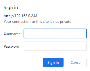
4. Open the browser, enter http://192.168.0.233 in the address bar, and then press Enter. 192.168.0.233 is the default management IP address of the device, and you can edit the address after login.
5. On the login page, enter the default username (admin) and password (admin), and then click Log In. As a best practice, change the login password immediately after the first successful login for security purposes. For configuration procedures, see "Account.”
Using the web interface
Overview
The top-level menus on the webpage navigation pane include Home, System, Monitoring, Switch Settings, VLAN Settings, and QoS Settings. Clicking on a top-level menu expands its submenu, displaying the feature names. Clicking on a feature name opens the webpage for configuring that feature.
Clicking the ![]() icon
on the bottom of the navigation pane opens the feedback page. The feedback page
is an important channel for communication with users, and we highly appreciate
your opinions. You can fill out the form with your functional suggestions,
views on the product interface, discovered bugs, and requirements for new
features. We will read every piece of feedback carefully and continuously
optimize our product based on your opinions. Thank you for your support and
understanding.
icon
on the bottom of the navigation pane opens the feedback page. The feedback page
is an important channel for communication with users, and we highly appreciate
your opinions. You can fill out the form with your functional suggestions,
views on the product interface, discovered bugs, and requirements for new
features. We will read every piece of feedback carefully and continuously
optimize our product based on your opinions. Thank you for your support and
understanding.
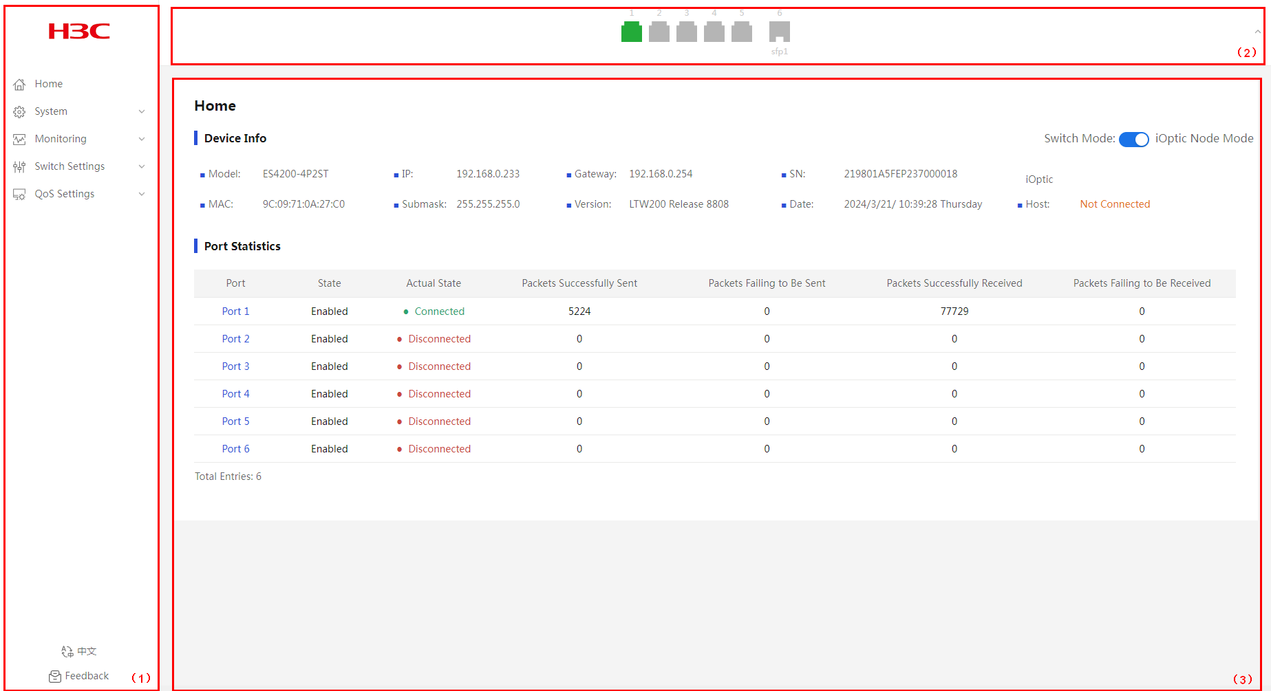
Webpage layout
Figure 2 Webpage layout
|
1) Navigation pane |
2) Port state pane |
|
3) Content pane |
|
As shown in the figure above, the webpage has the following functional areas:
· Navigation pane—Provides the Web menu for device functions in a tree structure. You
can easily select function menus in the navigation pane. The content pane
displays the selection result. You can click the H3C
logo on the top of the navigation pane to access the H3C official website, and
click the feedback icon ![]() on the bottom of the
navigation pane to open the feedback page.
on the bottom of the
navigation pane to open the feedback page.
· Port state pane—Displays port quantity and port state information.
¡ Click
the ![]() or
or ![]() icon on the
right of the port state pane to hide or display the port state pane.
icon on the
right of the port state pane to hide or display the port state pane.
¡ When the port state pane is displayed, the pane displays the port quantity and port physical state, and the information is refreshed every 10 seconds.
¡ Table 1 provides the port state description.
· Content pane—Allows users to perform configuration tasks, and view information and the operation result.
Table 1 Port state description
|
Port type |
Icon |
Description |
|
Copper port |
|
The port is disconnected. |
|
|
The port is connected. |
|
|
|
A loop was detected on the port, and loop protection was triggered. |
|
|
|
A loop was detected on the port. |
|
|
Fiber port |
|
The port is disconnected. |
|
|
The port is connected. |
|
|
|
A loop was detected on the port, and loop protection was triggered. |
|
|
|
A loop was detected on the port. |
Top-level menu items and features
Home
The homepage displays basic device information and port information.
System menu
Use Table 2 to navigate to the tasks you can perform from the System menu.
|
Menus |
Tasks |
|
IP Settings |
Configure device management IP. |
|
Account |
Manage account and password. |
|
System Restart |
Reboot the device |
|
System Upgrade |
Update system software. |
|
Restore to Factory |
Restore factory default settings. |
Monitoring menu
Use Table 3 to navigate to the tasks you can perform from the Monitoring menu.
Table 3 Monitoring menu navigator
|
Menus |
Tasks |
|
Port Statistics |
Display port statistics information. |
|
Cable Detection |
Perform cable diagnosis and analysis. |
|
Loop Prevention |
· Loop protection · Loop detection |
Switch Settings menu
Use Table 4 to navigate to the tasks you can perform from the Switch Settings menu.
Table 4 Switch Settings menu navigator
|
Menus |
Tasks |
|
Port Settings |
· Edit port state. · Configure port rate and duplex mode. · Configure traffic control. · Display port information. |
|
Port Mirroring |
· Enable/disable port mirroring. · Configure source and destination ports. · Display port mirroring information. |
|
Port Isolation |
· Enable/disable port isolation. · Display port isolation information. |
|
Static MAC |
· Add and delete static MAC address entries. · Configure MAC blocking. · Display MAC address information. |
|
MAC Search |
Filter MAC address entries. |
|
MAC List |
· Display existing MAC address entries. · Clear dynamic MAC address entries. |
|
DHCP Snooping |
· Enable/disable DHCP snooping. · Configure trusted and untrusted ports. · Display DHCP snooping information. |
|
PoE Settings |
· Enable/disable PoE for interfaces. · Display PoE information. |
VLAN Settings menu
Use Table 5 to navigate to the tasks you can perform from the VLAN Settings menu.
Table 5 VLAN Settings menu navigator
|
Menus |
Tasks |
|
VLAN Members |
· Enable/disable VLAN. · Create and delete VLANs. · Display static VLAN information. |
|
VLAN Settings |
· Enable/disable VLAN. · Divide VLANs based on ports. · Display port VLAN information. |
QoS Settings
Use Table 6 to navigate to the tasks you can perform from the QoS Settings menu.
Table 6 QoS Settings menu navigator
|
Menus |
Tasks |
|
Port Rate Limit |
· Enable/disable port rate limiting. · Display port bandwidth information. |
|
Storm Control |
· Enable/disable storm control. · Display storm control information. |
Home
Overview
The homepage displays device information and port information.
Device Info
Overview
A device can run in standalone mode or iOptic node mode.
· Standalone mode—A device in standalone mode can be managed through the webpage.
· iOptic node mode—A device in iOptic node mode can be managed through the webpage and SmartMC platform.
When a device runs in iOptic node mode, restarting the device restores its factory defaults.
Procedure
1. From the navigation pane, select Home.
2. You can view device information and switch device operating mode in the device information area. A device operates in iOptic node mode by default.
Figure 3 Homepage
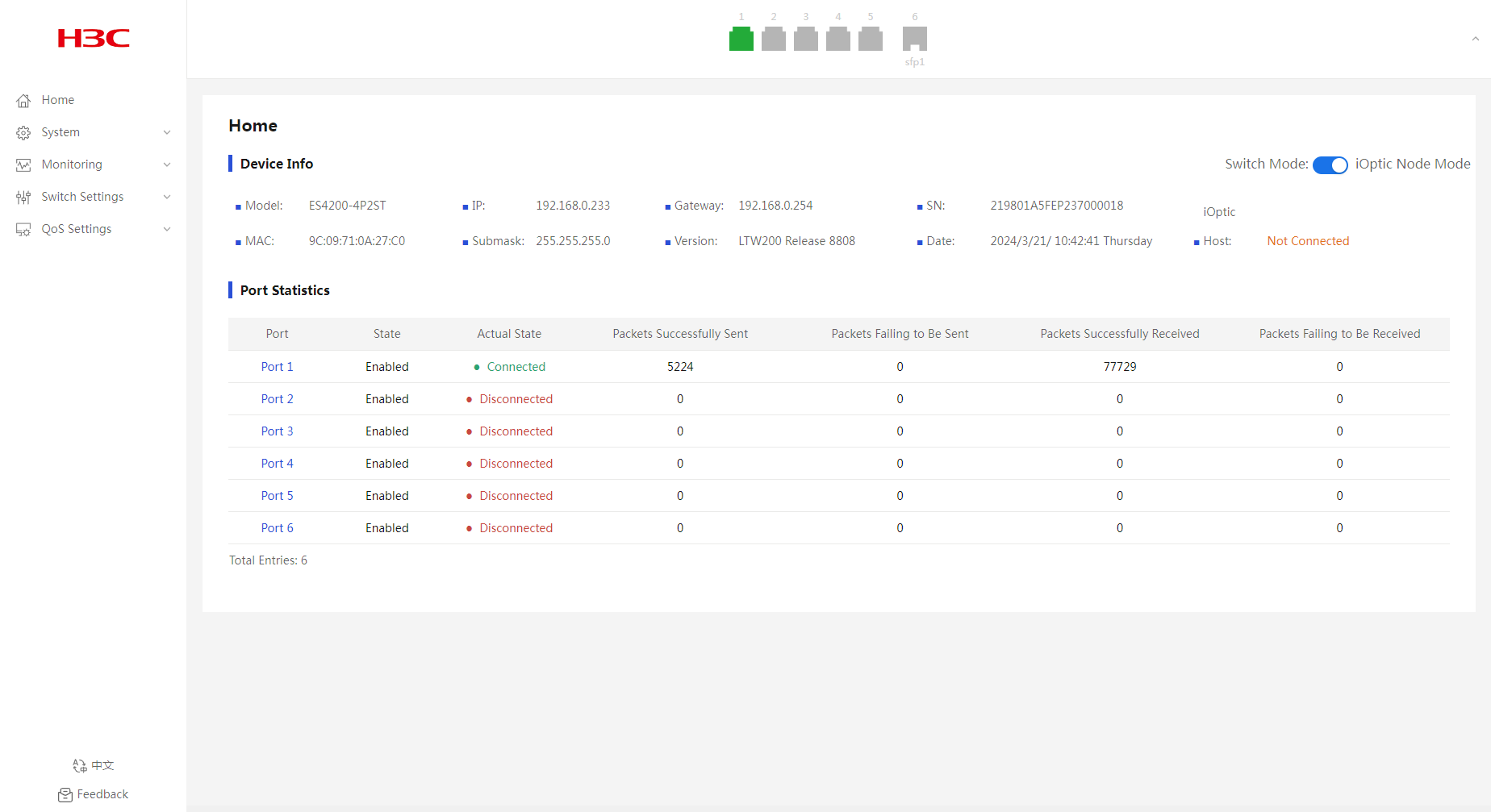
Port Statistics
1. From the navigation pane, select Home.
2. In the port statistics area, you can view port statistics information, including port physical state, packets sent successfully, and packets failed to be sent.
System
IP Settings
Configuring IP settings
1. From the navigation pane, select System > IP Settings.
2. Configure the DHCP enabling state.
¡ In standalone mode, DHCP is enabled by default.
¡ By default, a device in iOptic node mode is disabled with DHCP when it is not incorporated and enabled with DHCP after it is incorporated.
3. Select the management VLAN.
|
|
NOTE: The management VLAN feature is not supported when an ES4200 switch operates in iOptic node mode. |
4. Enter the management IP address, subnet mask, and gateway address.
5. Click Submit.
6. In the dialog box that opens, click OK.
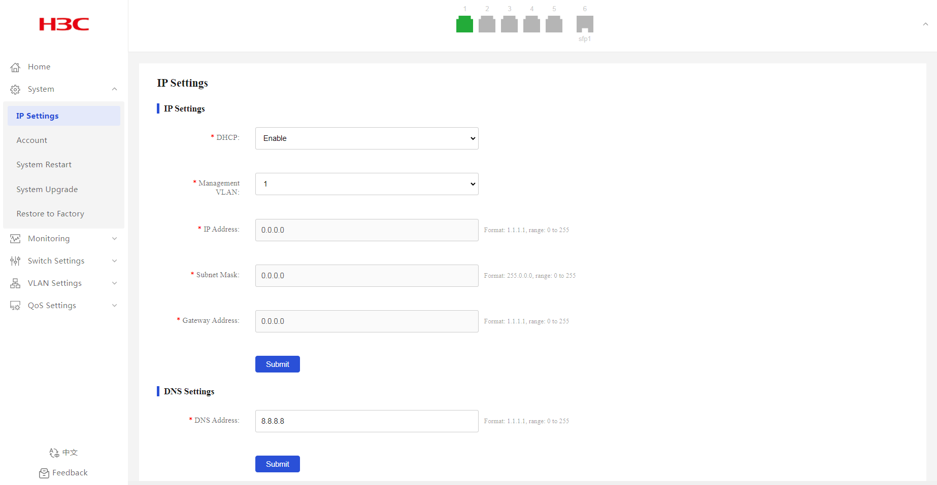
Configuring DNS settings
1. From the navigation pane, select System > IP Settings.
2. Enter the DNS address.
3. Click Submit.
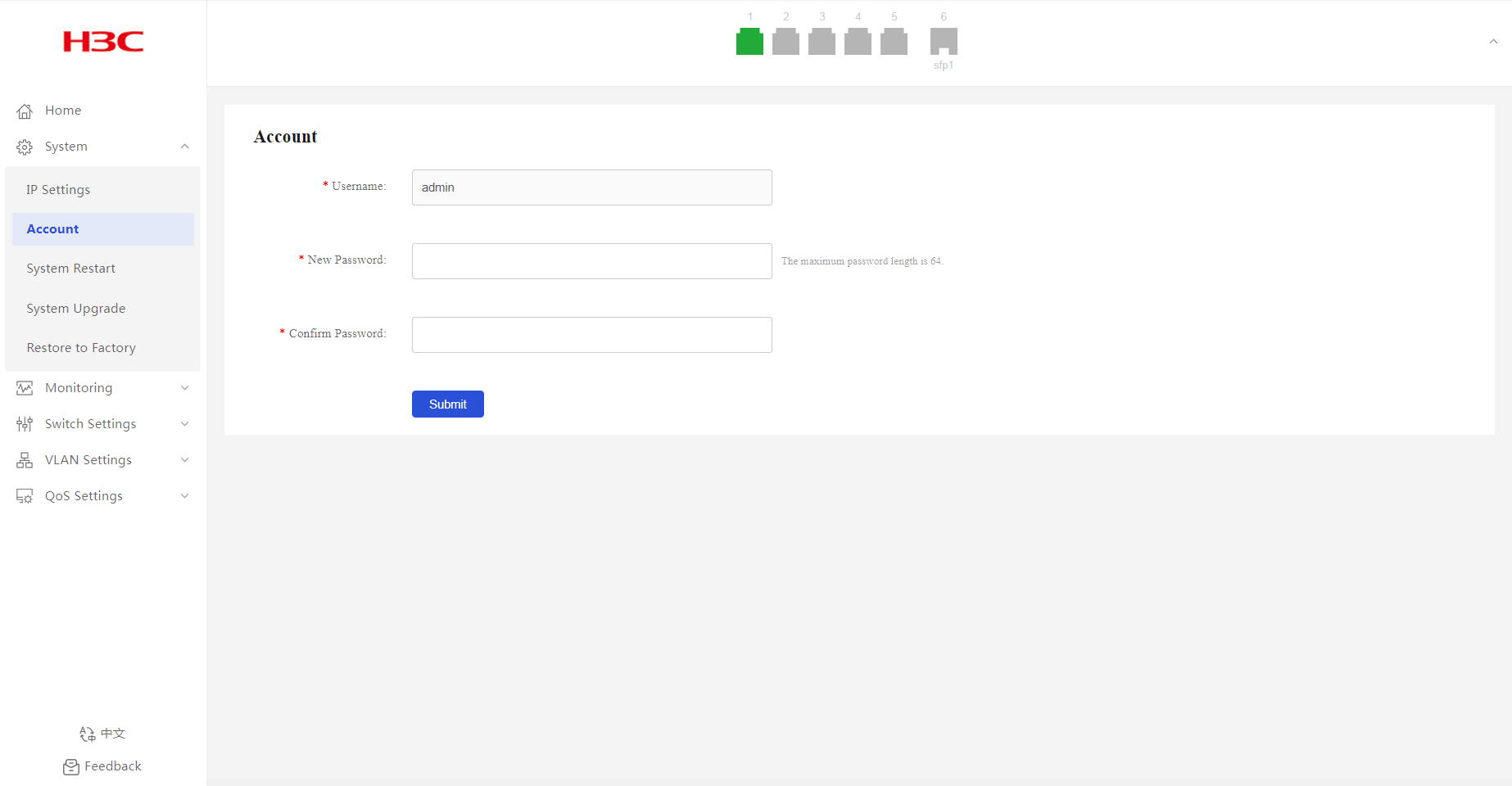
Account
1. From the navigation pane, select System > Account.
2. In the New Password field, enter a new password.
The default password is admin.
3. Enter the new password again in the Confirm Password field.
4. Click Submit.
Figure 6 Configuring account information
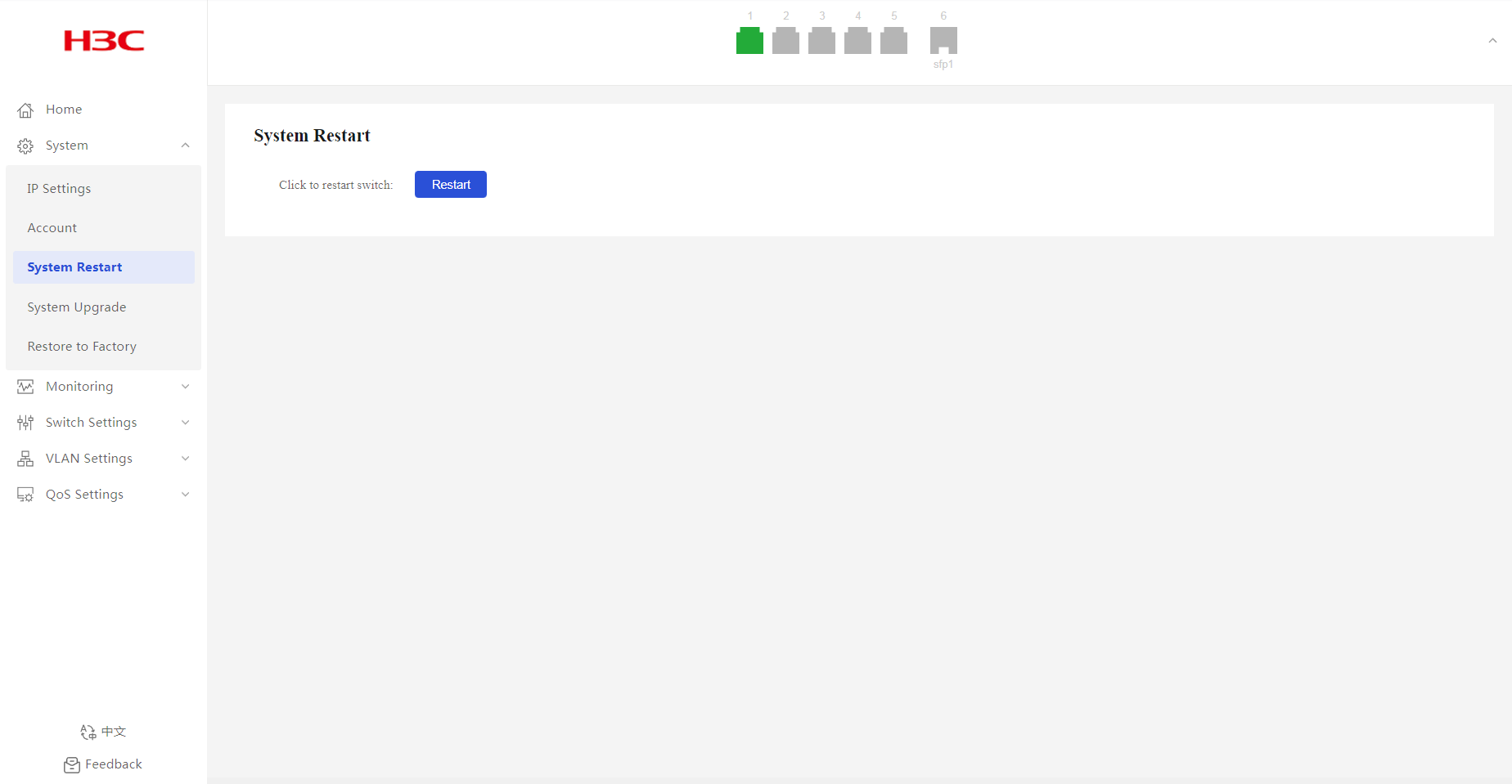
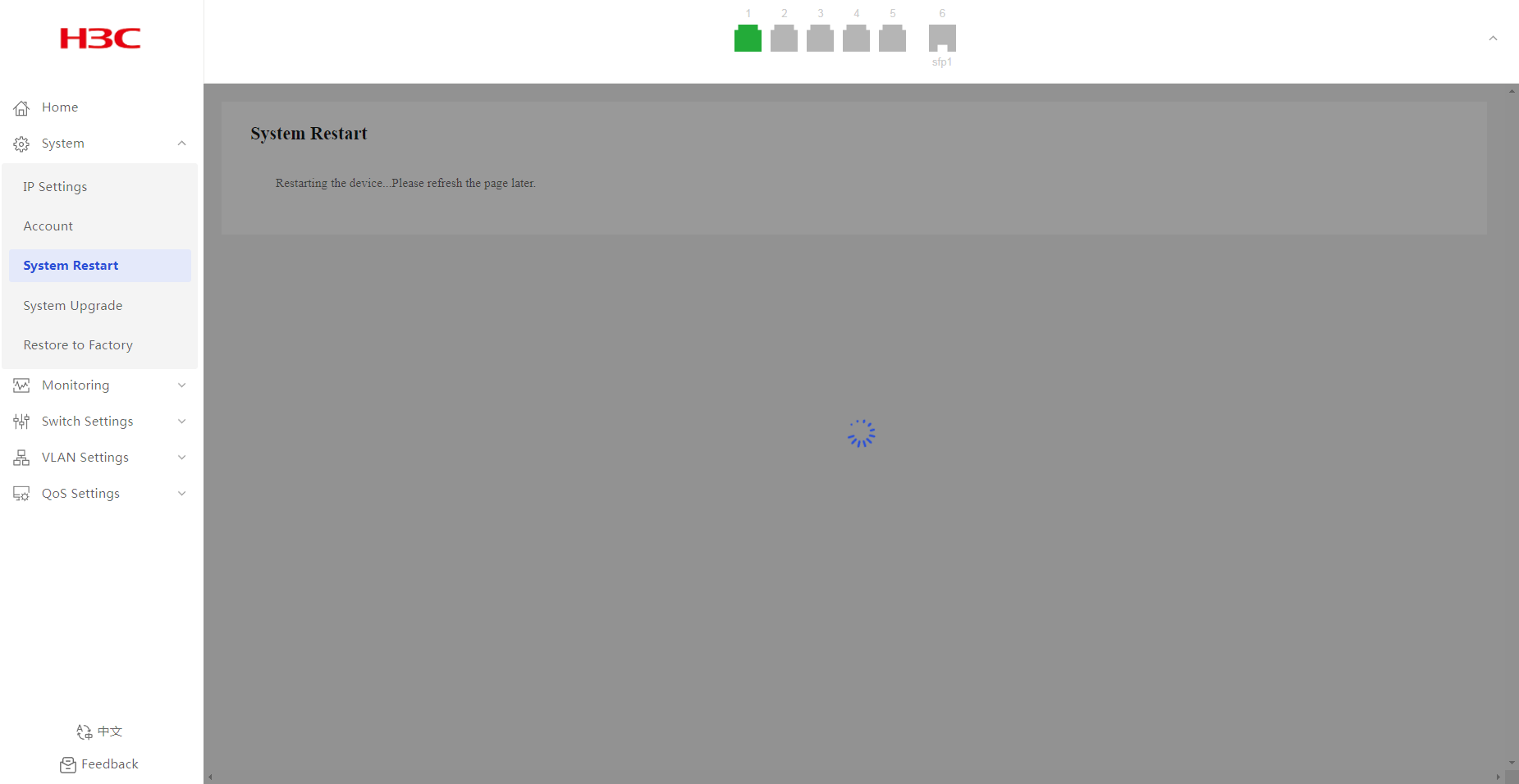
System Restart
1. From the navigation pane, select System > System Restart.
2. Click Restart. Refresh the webpage later to re-enter the system.
System Upgrade
1. From the navigation pane, select System > System Upgrade.
2. Click Select File, and then select the target local file.
3. Click Upgrade.
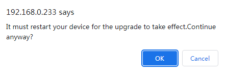
4. In the dialog box that opens, click OK. Refresh the webpage after the file is uploaded successfully to re-enter the system.
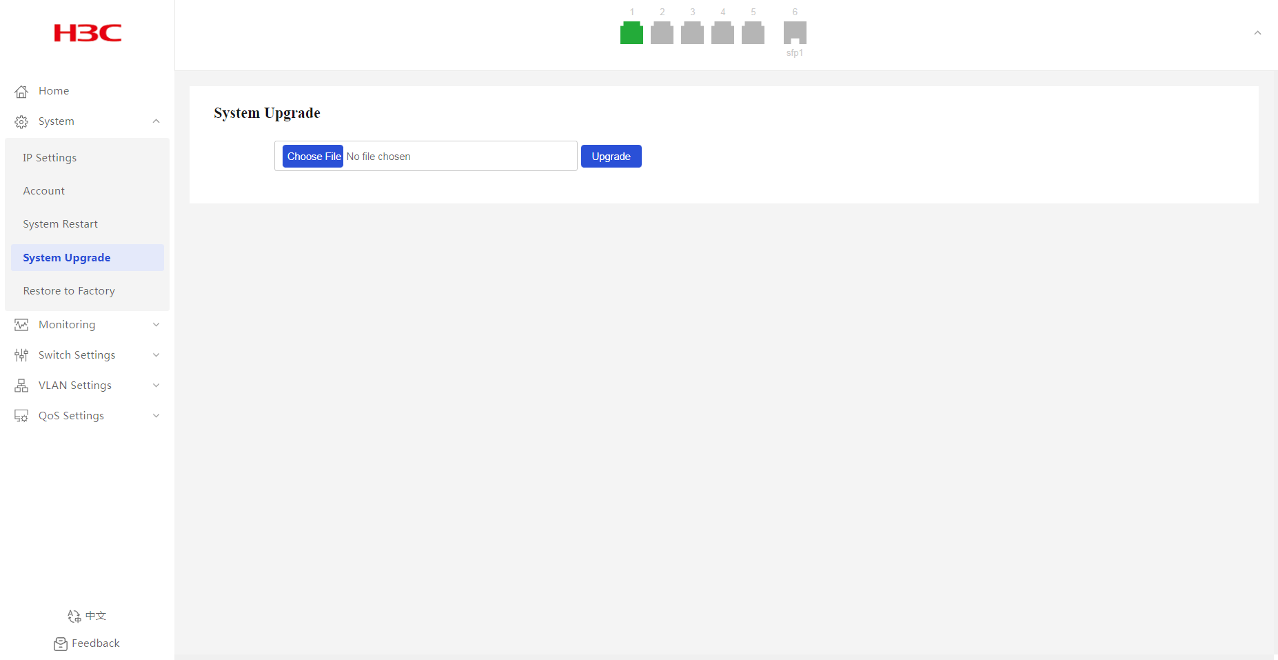
Figure 10 Confirming operation
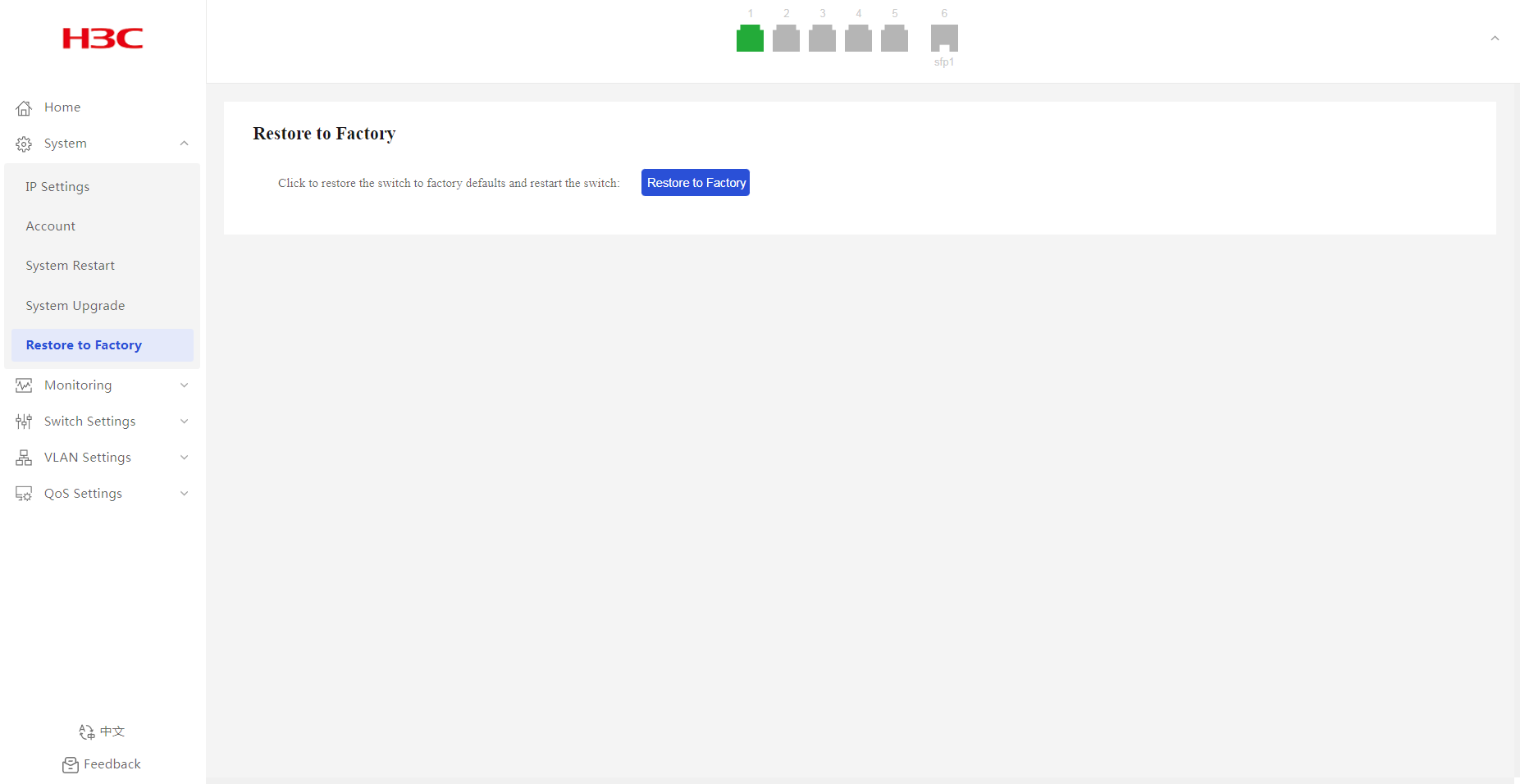
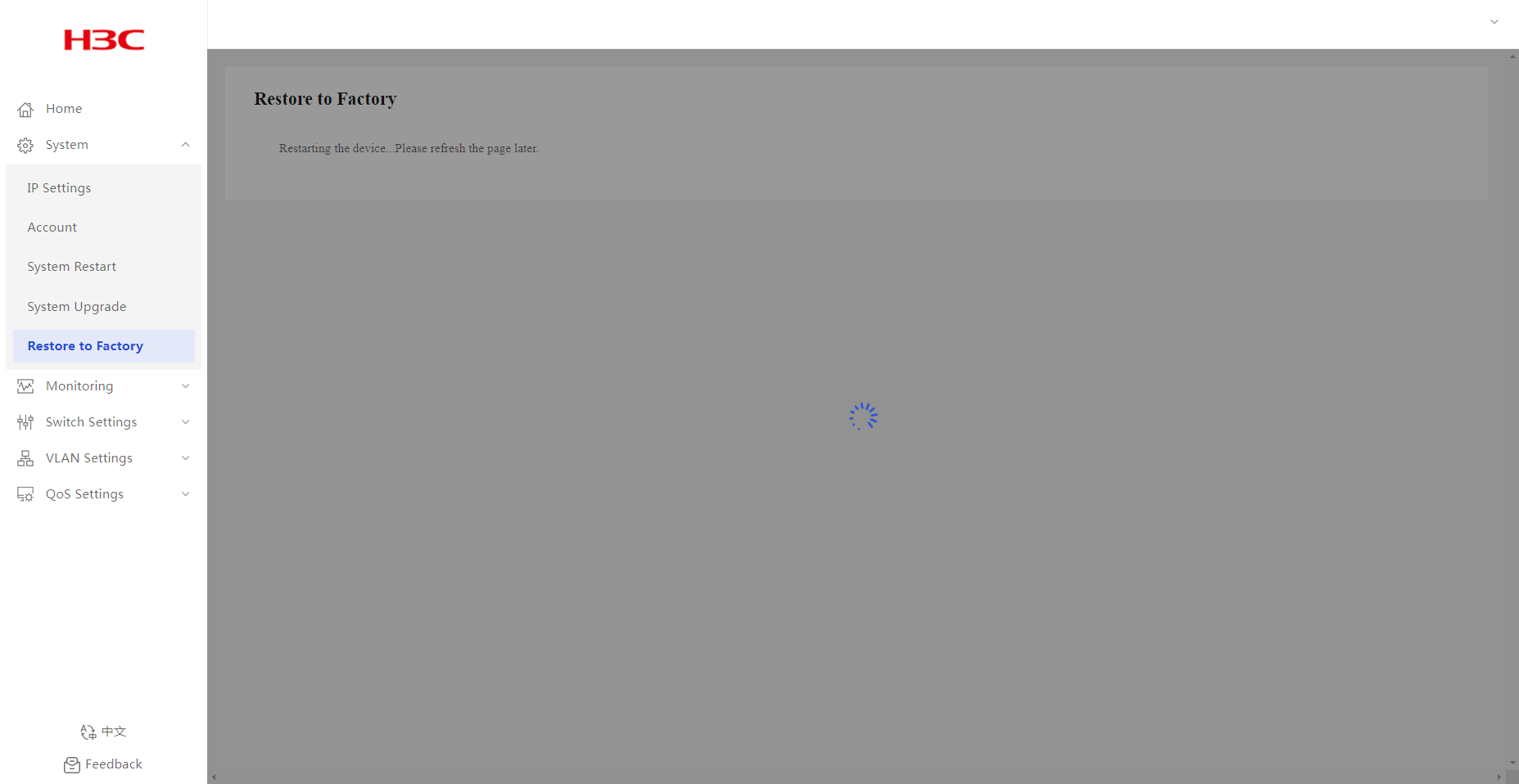
Restore to Factory
1. From the navigation pane, select System > Restore to Factory.
2. Click Restore to Factory. Wait for the restoration to complete.
Figure 11 Restoring factory default settings
Monitoring
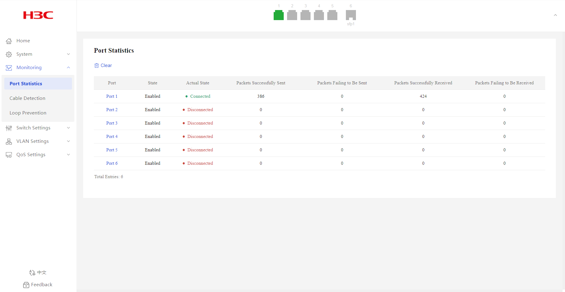
Port Statistics
1. From the navigation pane, select Monitoring > Port Statistics.
2. You can view port statistics information, including port physical state, packets sent successfully, and packets failed to be sent.
Figure 13 Port statistics page
Cable Detection
Overview
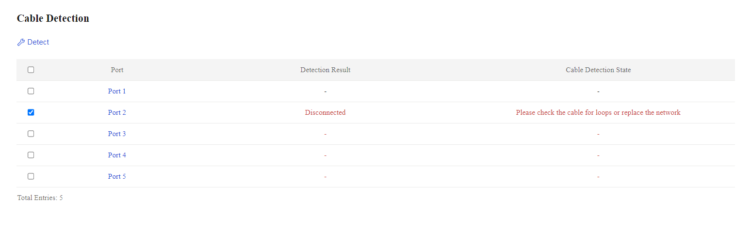
Table 7 Cable detection results
|
Detection result |
Description |
|
Error |
Failed to obtain data. |
|
Short Circuit |
Verify whether a loop exists or change the cable. |
|
Disconnected |
Verify whether a loop exists or change the cable. |
|
Mismatch |
Verify whether a loop exists or change the cable. |
|
Connected |
The cable is in good condition. |
Restrictions and guidelines
Administratively shut down ports do not support cable detection.
Procedure
1. From the navigation pane, select Monitoring > Cable Detection.
2. Select the target ports.
3. Click the detect icon ![]() .
.
Figure 14 Cable detection page
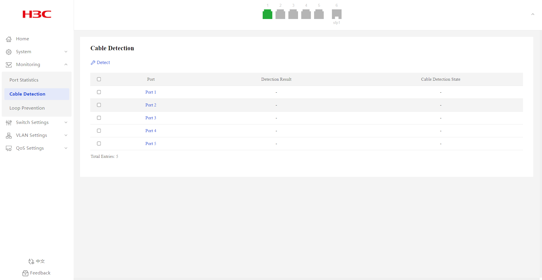
Figure 15 Cable detection results
Loop Prevention
Overview
Background
The loop detection mechanism performs periodic checks for Layer 2 loops. The mechanism immediately generates a log message when a loop occurs so that you are promptly notified to adjust network connections and configurations.
· Loop detection—When the system detects a loop on a port, it does not take any actions on the port, but it will display a red icon for the port on the port state pane.
· Loop protection—When the system detects a loop on a port, it automatically blocks that port to avoid packet flooding. The system also displays the port as blocked in the Port Loop Info list and the port state pane (yellow icon).
Loop prevention interval
Loop detection is a continuous process as the network changes. Loop detection frames are sent at the loop detection intervals to determine whether loops occur on ports and whether loops are removed.
Port state auto recovery
When the device detects a loop on a port and does not receive any loop detection packets within the recovery interval, it assumes that the loop has been eliminated. The port is then automatically restored to normal forwarding state. This process is the automatic port state recovery process.
Hardware and feature compatibility
Support for this feature varies by device model.
|
Product model |
Description |
|
· ES4200-2T1S-M · ES4200-4T1MS-B · ES4200-4T2RMS-B · ES4200-4P2RMS-B · ES4200-8T2RS · ES4200-8P2RS · ES4200-4T2ST · ES4200-4P2ST · ES4200-8T2ST · ES4200-8P2ST · ES4200-8T2S · ES4200-8P2S · ES4200-4P2RS · ES4200-4P2RST |
Support configuring loop detection and loop protection, and related parameters |
|
· ES4200-8P2RX-B · ES4200-16P2RX-B · ES4200-16T2RX · ES4200-16P2RS |
Support only loop protection. Both the detection interval and the recovery interval are 5 seconds. |
Procedure
Enabling or disabling loop protection
1. From the navigation pane, select Monitoring > Loop Prevention.
2. Enable or disable the loop protection feature.
By default, loop protection is enabled.
Configuring loop protection and loop detection
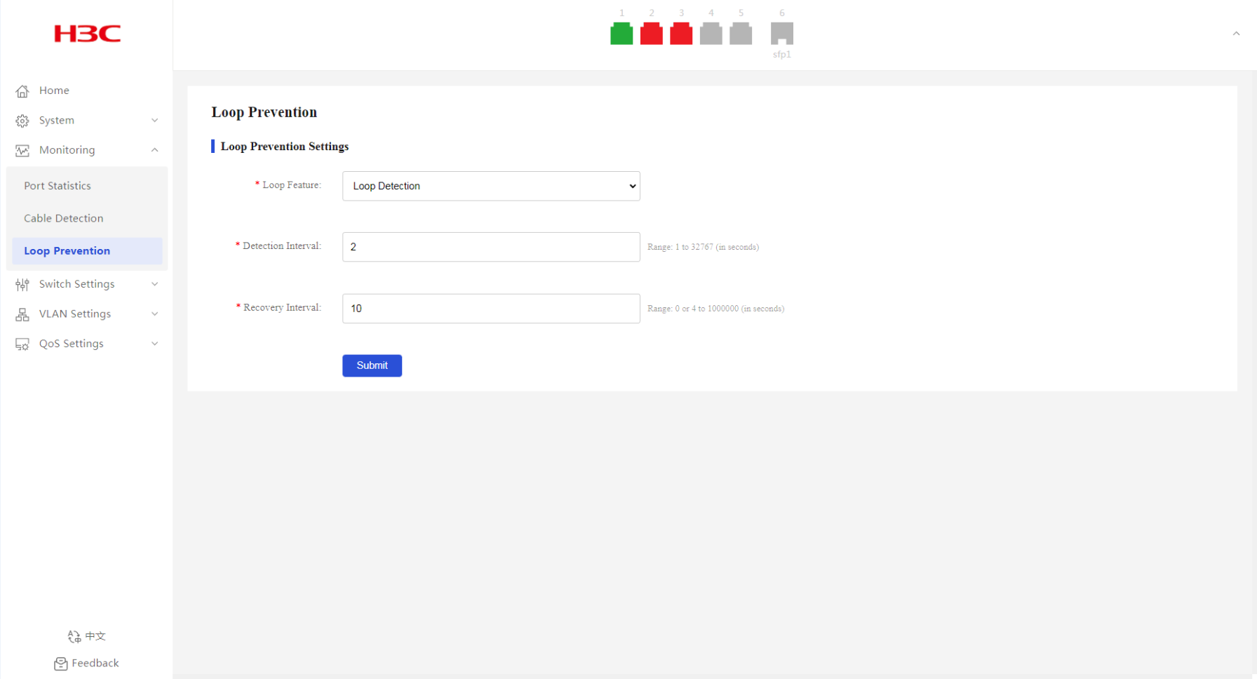
1. From the navigation pane, select Monitoring > Loop Prevention.
2. To configure loop protection:
¡ Select Loop Protection from the Loop Feature list.
¡ Configure the detection interval. The default interval is two seconds.
¡ Configure the recovery interval. The default interval is 10 seconds.
3. To configure loop detection:
¡ Select Loop Detection from the Loop Feature list.
¡ Configure the detection interval. The default interval is two seconds.
¡ Configure the recovery interval. The default interval is 10 seconds.
4. Click Submit.
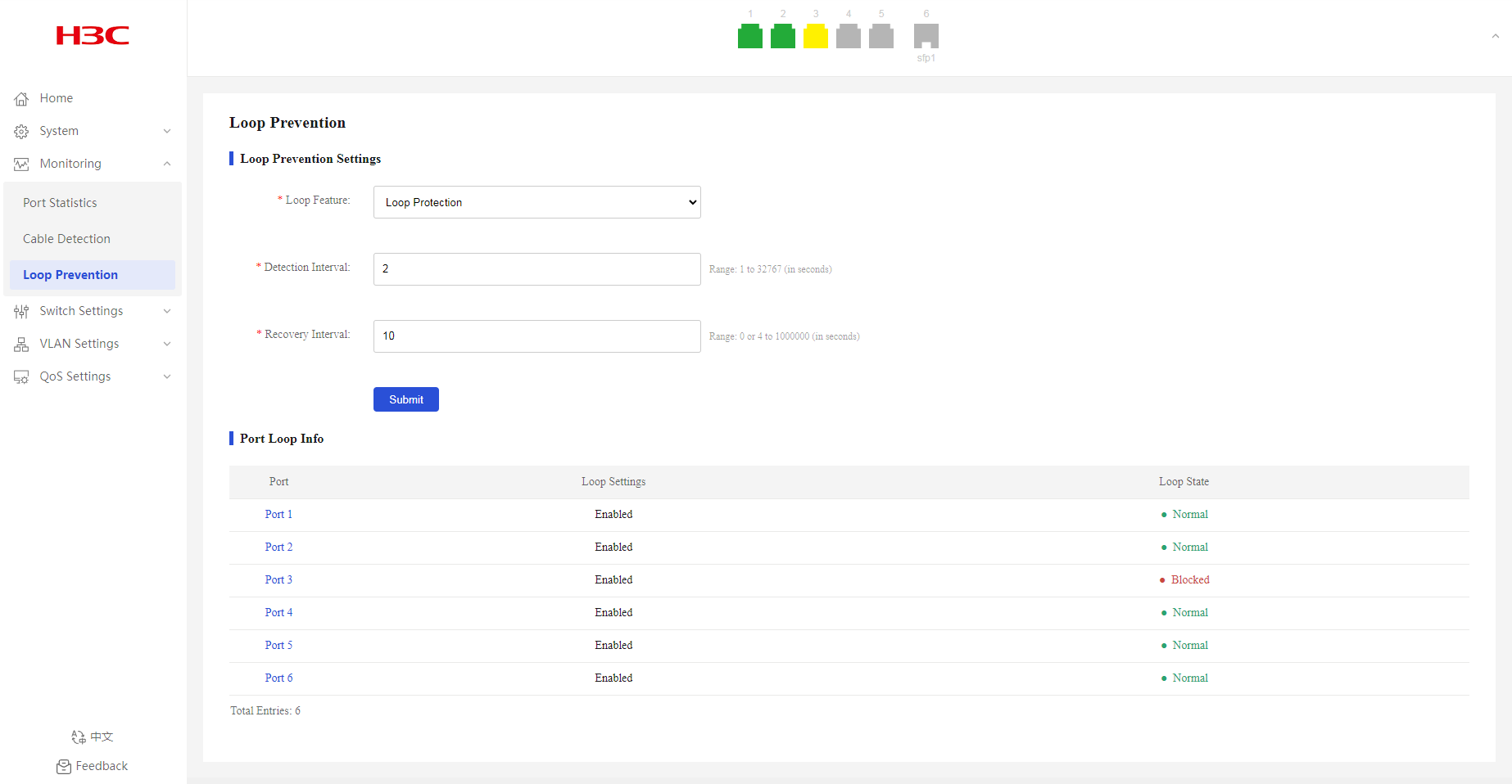
Displaying port loop information
After enabling loop prevention, you can view the port state information:
· As shown in Figure 18, port 3 is blocked because a loop is detected on it.
· As shown in Figure 19, port 2 and port 3 are displayed with a red icon on the port state pane because a loop is detected.
Figure 16 Loop prevention page
Figure 17 Loop prevention page

Configuration examples
Example: Configuring basic loop detection functions
Network configuration
As shown in Figure 20, configure loop detection on Device A to automatically shut down the interface on which a loop is detected.

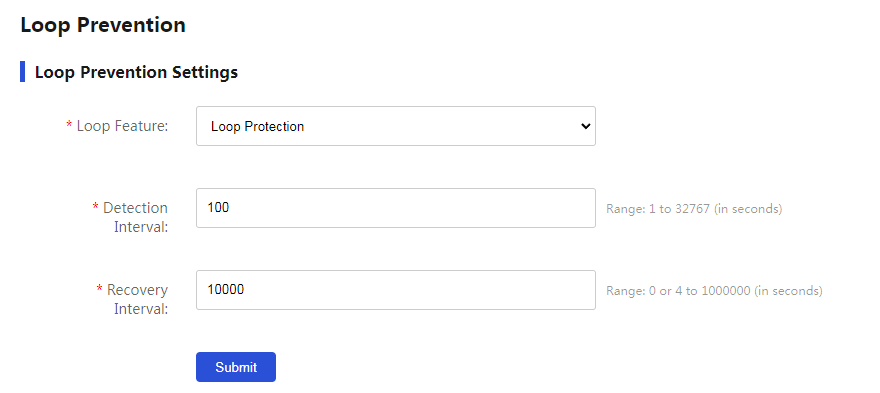
Procedure
1. From the navigation pane, select Monitoring > Loop Prevention.
2. Select Loop Protection from the Loop Feature list.
3. Set the detection interval to 100 milliseconds.
4. Set the recovery interval to 10000 milliseconds.
5. Click Submit.
Figure 21 Loop prevention page
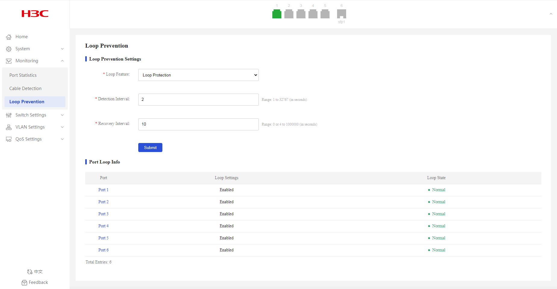
Figure 22 Loop protection
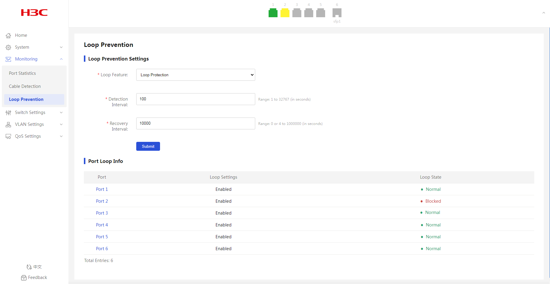
Verifying the configuration
As shown in Figure 23, when a loop is detected on port 2, you can view that port 2 is blocked and its icon is displayed in yellow.
Figure 23 Port loop information
Switch Settings
Port Settings
Overview
This feature allows you to view the physical state, operating mode, rate, and traffic control information about each port and edit port settings.
Interface rate
Generally, a device automatically negotiates the rate of an Ethernet interface with the peer device. The negotiated rate can be any rate within the rate capability range. To allow the interface to use only specific rates, you can configure auto negotiation rate settings.
Operating mode
You can configure an Ethernet interface to operate in one of the following duplex modes:
· Full duplex mode—The interface can send and receive packets simultaneously.
· Half duplex mode—The interface can only send or receive packets at a given time.
· Auto negotiation mode—The interface negotiates a duplex mode with its peer.
Flow control
With flow control enabled, when traffic congestion occurs at the receiving end, the receiving end sends a flow control (Pause) frame to ask the sending end to suspend sending packets.
Configuring port settings
1. From the navigation pane, select Switch Settings > Port Settings.
2. From the Port Settings list, select the ports to configure.
3. Bring up or shut down the ports. By default, a port is up.
4. Select a rate and duplex mode. By default, the auto mode is used.
5. Enable or disable flow control. By default, flow control is enabled.
6. Click Submit.
Figure 24 Configuring port settings
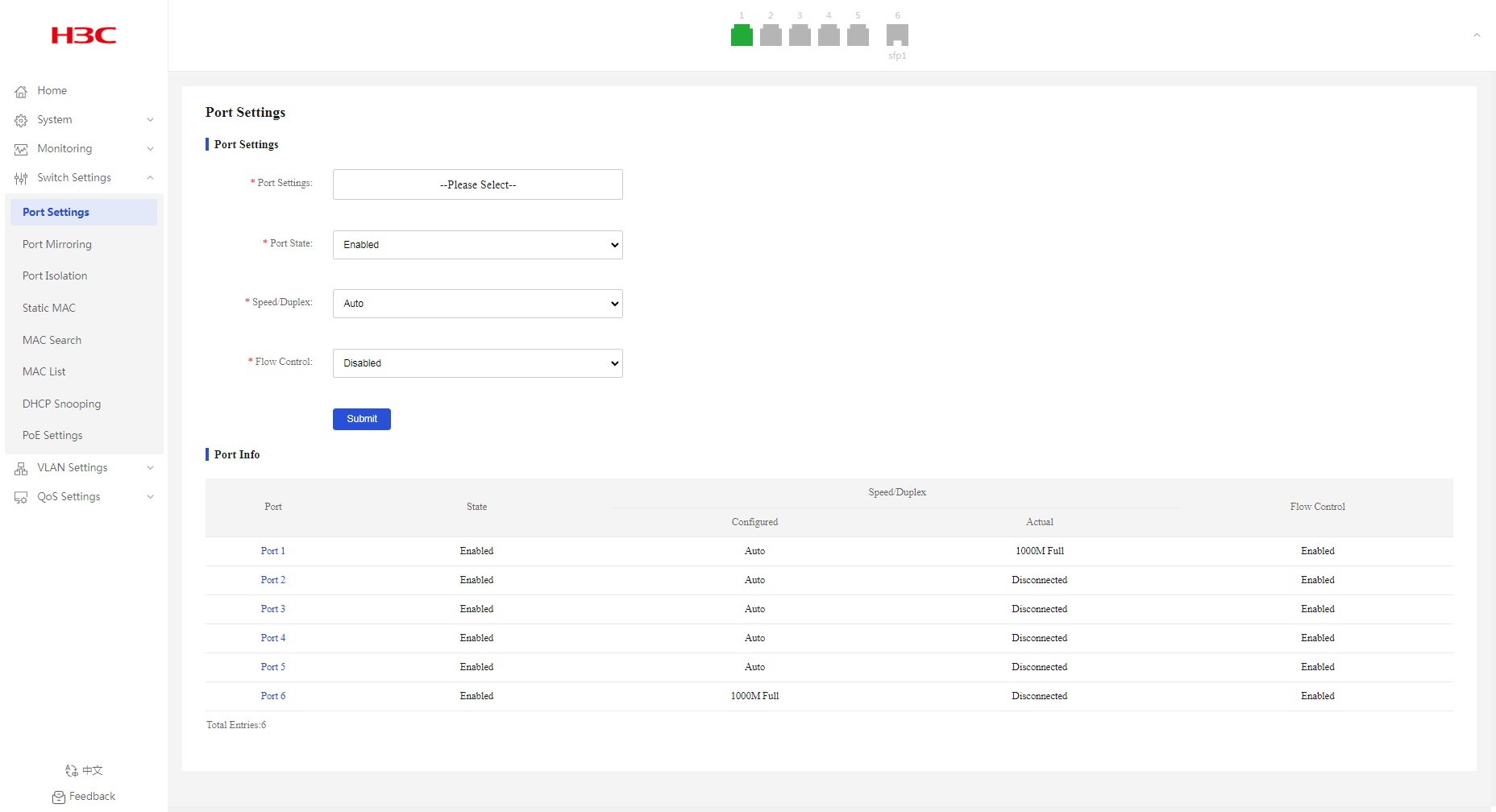
Port Info
1. From the navigation pane, select Switch Settings > Port Settings.
2. You can view port information in the Port Info area.
Port Mirroring
Overview
Port mirroring copies the packets passing through a port to the destination port that connects to a data monitoring device for packet analysis.
Concepts
Mirroring source
Monitored port on the device. Packets of the monitored port will be copied and sent to the destination port.
Mirroring destination
Port that connects to the data monitoring device. Packets of the source port will be copied and sent to the destination port.
Mirroring direction
Direction of packets copied on a mirroring source.
· Rx—Copies only packets received by the source port.
· Tx—Copies only packets sent by the source port.
· Both—Copies packets sent and received by the source port.
Configuring port mirroring
1. From the navigation pane, select Switch Settings > Port Mirroring.
2. Select a mirroring direction. By default, port mirroring is disabled.
3. Select the monitor and source ports.
4. Click Submit.
Figure 25 Configuring port mirroring

Displaying and clearing port mirroring information
1. From the navigation pane, select Switch Settings > Port Mirroring.
2. You can view port mirroring information in the Port Mirroring Info area.
3. To clear port mirroring information, click
the delete icon ![]() .
.
Port Isolation
Overview
The port isolation feature isolates Layer 2 traffic for data privacy and security without using VLANs.
Configuring port isolation settings
1. From the navigation pane, select Switch Settings > Port Isolation.
2. Enable or disable port isolation. By default, port isolation is disabled.
3. In the dialog box that opens, click OK.
Figure 26 Configuring port isolation settings
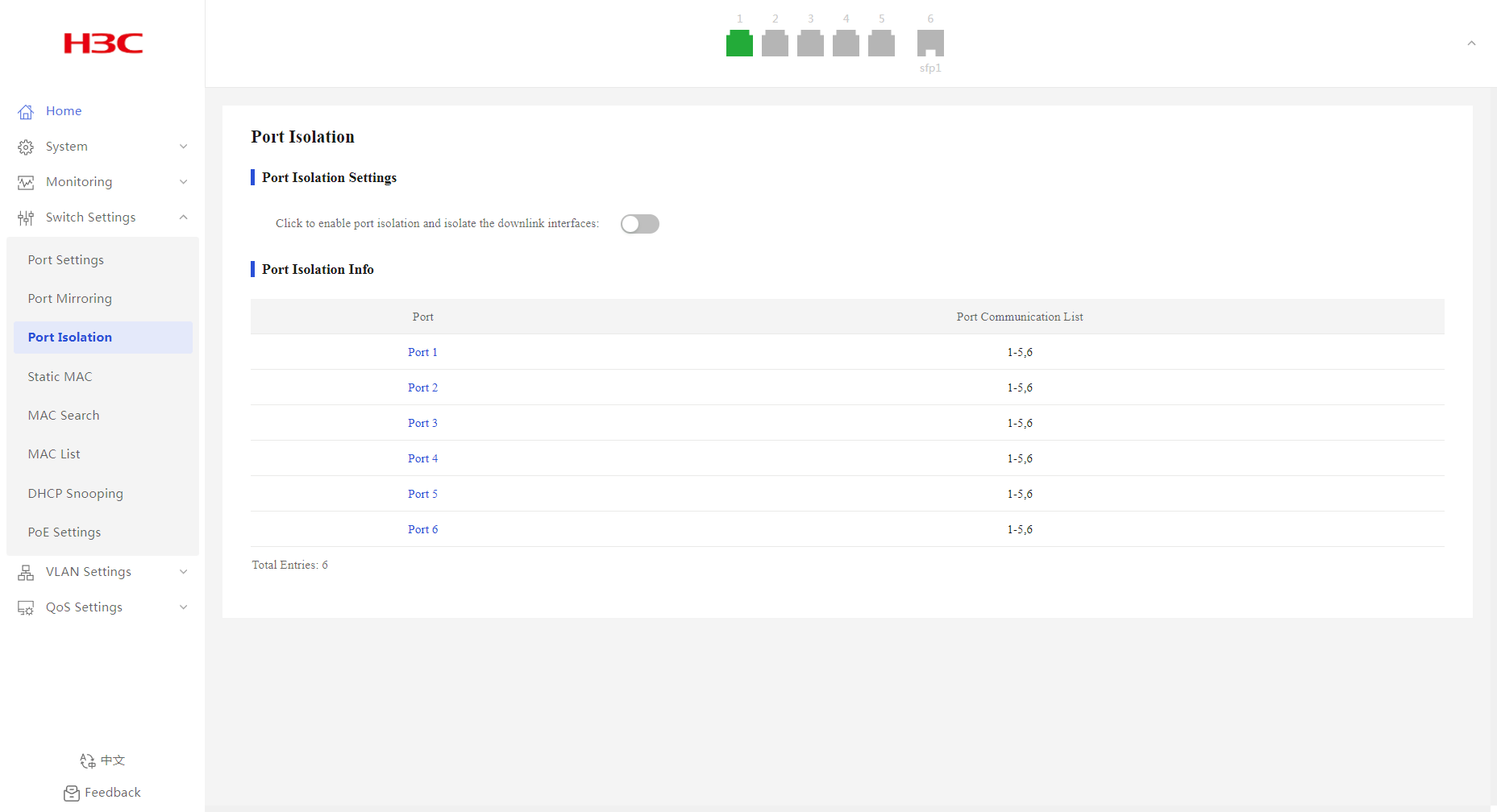
Figure 27 Confirming operation
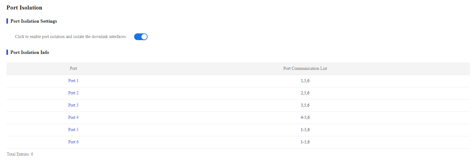
Displaying port isolation information
1. From the navigation pane, select Switch Settings > Port Isolation.
2. You can view port isolation information in the Port Isolation Info area.
Static MAC
Overview
An Ethernet device uses a MAC address table to forward frames. A MAC address entry includes a destination MAC address, an outgoing interface, and a VLAN ID. When the device receives a frame, it uses the destination MAC address of the frame to look for a match in the MAC address table.
· The device forwards the frame out of the outgoing interface in the matching entry if a match is found.
· The device floods the frame in the VLAN of the frame if no match is found.
MAC address entry generation
The entries in the MAC address table include entries automatically learned by the device and entries manually added.
MAC address learning
The device can automatically populate its MAC address table by learning the source MAC addresses of incoming frames on each interface.
The device performs the following operations to learn the source MAC address of incoming packets:
1. Checks the source MAC address (for example, MAC-SOURCE) of the frame.
2. Looks up the source MAC address in the MAC address table.
¡ The device updates the entry if an entry is found.
¡ The device adds an entry for MAC-SOURCE and the incoming port if no entry is found.
For security and efficient use of table space, the MAC address table uses an aging timer for each dynamic MAC address entry. If a dynamic MAC address entry is not updated before the aging timer expires, the device deletes the entry. This aging mechanism ensures that the MAC address table can promptly update to accommodate latest network topology changes.
Manually configuring MAC address entries
Dynamic MAC address learning does not distinguish between illegitimate and legitimate frames, which can invite security hazards. When Host A is connected to Port A, a MAC address entry will be learned for the MAC address of Host A (for example, MAC A). When an illegal user sends frames with MAC A as the source MAC address to Port B, the device performs the following operations:
· Learns a new MAC address entry with Port B as the outgoing interface and overwrites the old entry for MAC A.
· Forwards frames destined for MAC A out of Port B to the illegal user.
As a result, the illegal user obtains the data of Host A. To improve the security for Host A, manually configure a static entry to bind Host A to Port A. Then, the frames destined for Host A are always sent out of Port A. Other hosts using the forged MAC address of Host A cannot obtain the frames destined for Host A.
Types of MAC address entries
A MAC address table can contain the following types of entries:
· Static entries—A static entry is manually added to forward frames with a specific destination MAC address out of the associated interface, and it never ages out.
· Dynamic entries—A dynamic entry is dynamically learned to forward frames with a specific destination MAC address out of the associated interface. A dynamic entry might age out.
Blackhole entries
A blackhole entry is manually configured and never ages out. A blackhole entry is configured for filtering out frames with a specific source or destination MAC address. For example, to block all frames destined for or sourced from a user, you can configure the MAC address of the user as a blackhole MAC address entry.
Configuring static MAC address settings
1. From the navigation pane, select Switch Settings > Static MAC.
2. Enter the target MAC address.
3. Enter the ID of the VLAN to which the interface belongs.
4. Select the outgoing interface from the port list.
5. Enable MAC blocking as needed. By default, MAC blocking is disabled.
6. Click Add.
Figure 28 Configuring static MAC address settings
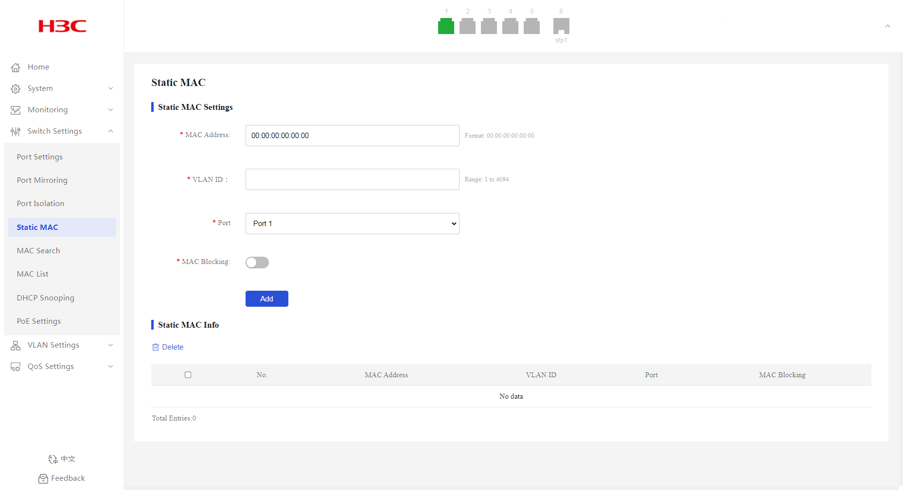
Displaying static MAC addresses
1. From the navigation pane, select Switch Settings > Static MAC.
2. You can view the static MAC addresses in the Static MAC Info area.
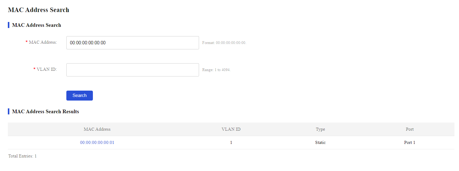
Filtering MAC addresses
1. From the navigation pane, select Switch Settings > MAC Search.
2. Enter the target MAC address and its VLAN ID, and then click Search.
The page will display the filtering result.
Figure 29 MAC address filtering
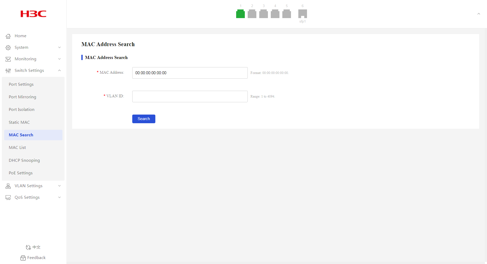
Figure 30 MAC address filtering result
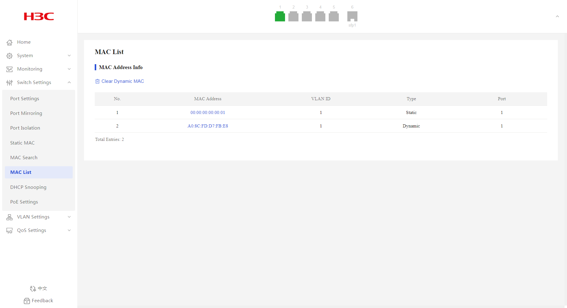
MAC List
1. From the navigation pane, select Switch Settings > MAC List.
2. You can view the MAC address information.
Figure 31 MAC address list
DHCP Snooping
Overview
DHCP snooping is a security feature for DHCP.
DHCP snooping works between the DHCP client and server, or between the DHCP client and DHCP relay agent. When a DHCP snooping device is located between a DHCP server and a DHCP relay agent, the DHCP snooping feature does not take effect.
DHCP snooping benefits
DHCP snooping guarantees that DHCP clients obtain IP addresses from authorized DHCP servers. DHCP snooping defines trusted and untrusted ports to make sure clients obtain IP addresses only from authorized DHCP servers.
· Trusted—A trusted port can forward DHCP messages correctly to make sure the clients get IP addresses from authorized DHCP servers.
· Untrusted—An untrusted port discards received DHCP-ACK and DHCP-OFFER messages to prevent unauthorized servers from assigning IP addresses.
Configure the DHCP snooping device's ports facing the DHCP server as trusted ports, and configure other ports as untrusted ports. The trusted port forwards response messages from the DHCP server to the client. The untrusted port connected to the unauthorized DHCP server discards incoming DHCP response messages.
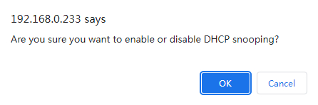
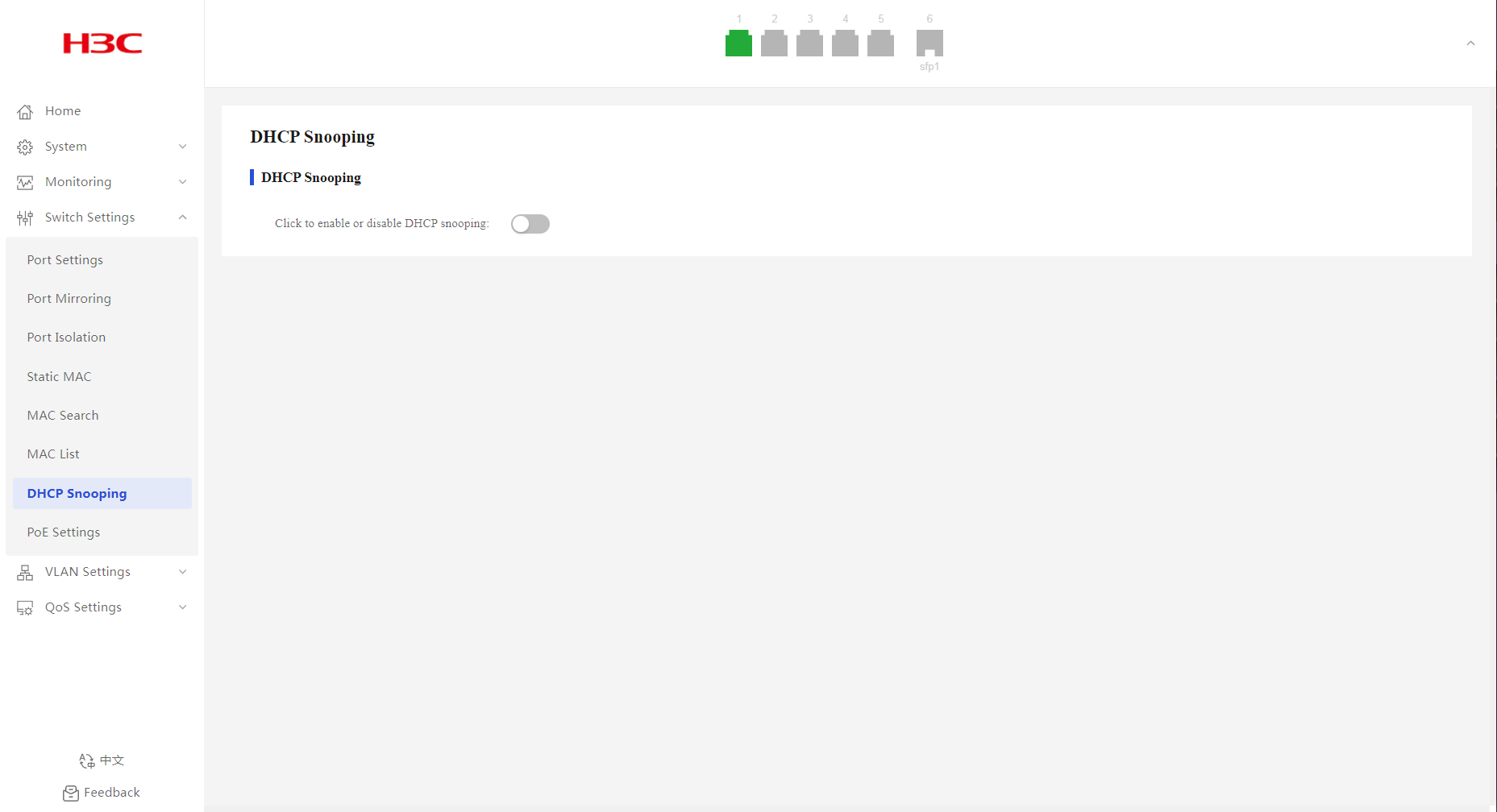
Configuring DHCP snooping
1. From the navigation pane, select Switch Settings > DHCP Snooping.
2. Configure the DHCP snooping feature state, and then click OK in the dialog box that opens.
By default, DHCP snooping is disabled.
3. Configure DHCP snooping settings:
a. Select the trusted or untrusted port state. By default, all ports on the device are trusted ports after DHCP snooping is enabled.
b. Select the target ports from the port list.
c. Click Submit.

Figure 33 Confirming operation
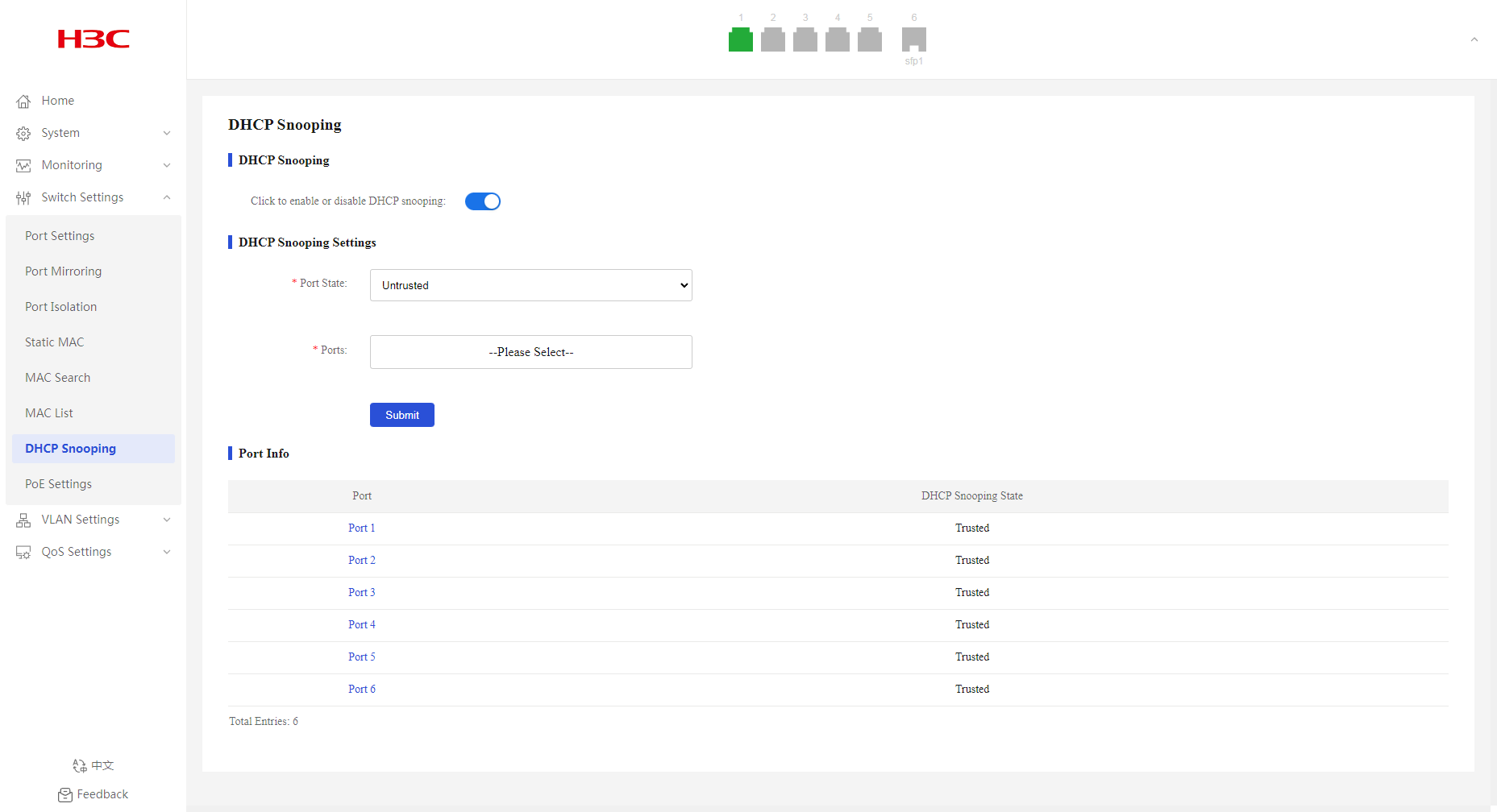
Displaying DHCP snooping information
1. From the navigation pane, select Switch Settings > DHCP Snooping.
2. You can view DHCP snooping information in the Port Info area.
PoE Settings
Overview
Power over Ethernet (PoE) enables a device to supply power for powered devices (PDs) over twisted pair cables.
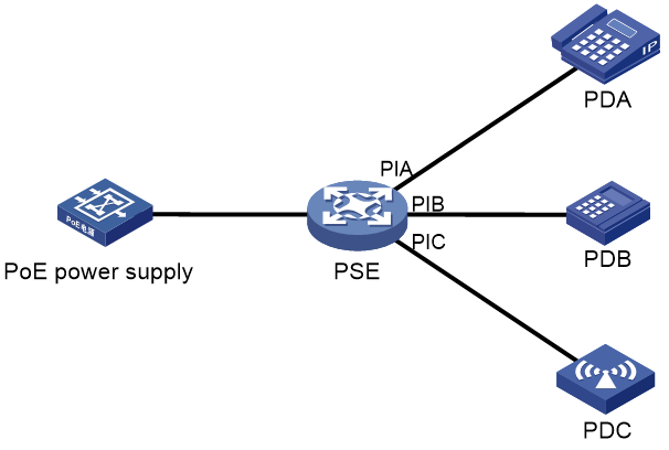
PoE system
As shown in Figure 35, a PoE system includes the following elements:
· PoE power supply—A PoE power supply provides power for the entire PoE system.
· PSE—A power sourcing equipment (PSE) supplies power to PDs.
· PI—A power interface (PI) is a PoE-capable Ethernet interface on a PSE.
· PD—A powered device (PD) receives power from a PSE. PDs include IP telephones, APs, portable chargers, POS terminals, and Web cameras. You can also connect a PD to a redundant power source for reliability.
Procedure
1. From the navigation pane, select Switch Settings > PoE Settings.
2. In the PoE Info area, configure the PoE state for the target port. By default, PoE is enabled for a port.
3. In the dialog box that opens, click OK.
Figure 36 PoE settings page
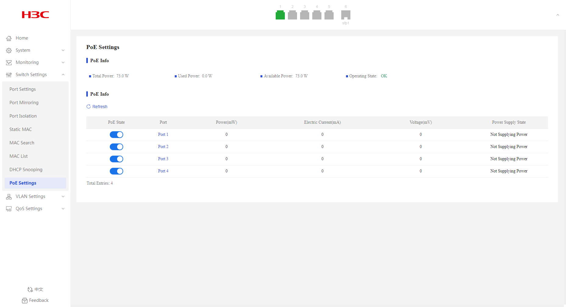
Figure 37 Confirming operation
Configuration examples
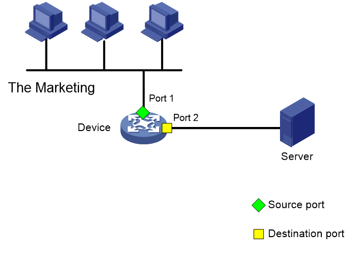
Example: Configuring port mirroring
Network configuration
As shown in Figure 38, the device connects to the marketing and technology departments through port 1 and to the server through port 2. Configure local port mirroring in source port mode to enable the server to monitor the bidirectional traffic of the two departments.
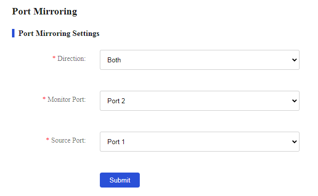
Procedure
1. From the navigation pane, select Switch Settings > Port Mirroring.
2. Select Both in the direction list.
3. Select port 2 as the monitor port, and select port 1 as the source port.
4. Click Submit.
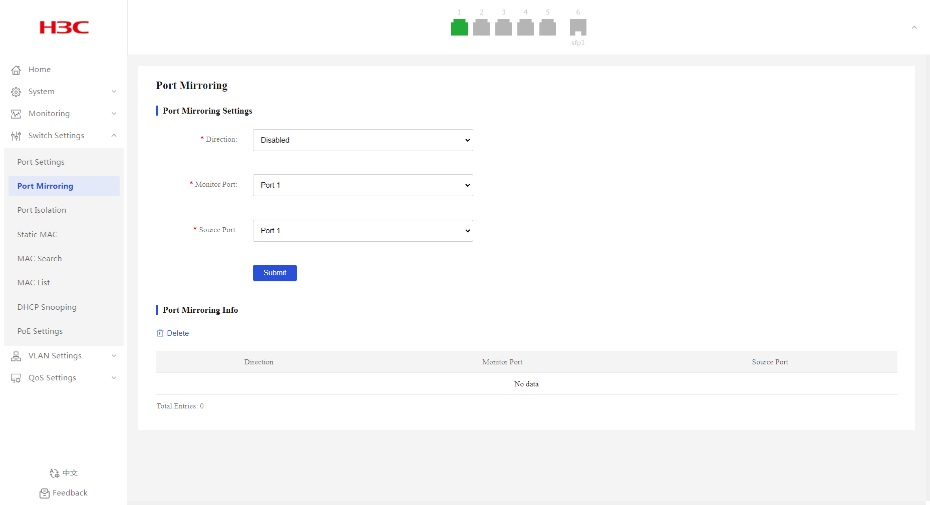
Figure 40 Configuring port mirroring
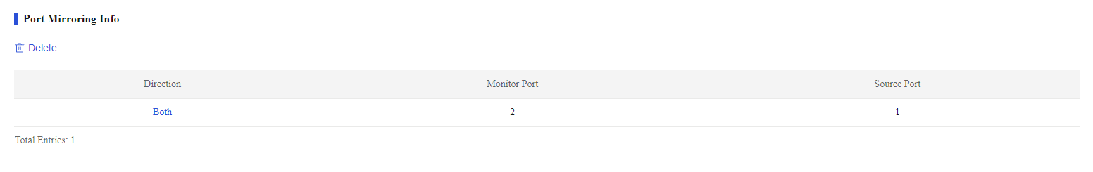
Verifying the configuration
As shown in Figure 41, the port mirroring direction is both, the monitor port is port 2, and the source port is port 1. Verify that you can monitor the incoming packets and outgoing packets of the marketing and technology departments on the server.
Figure 41 Port mirroring information
Example: Configuring port isolation
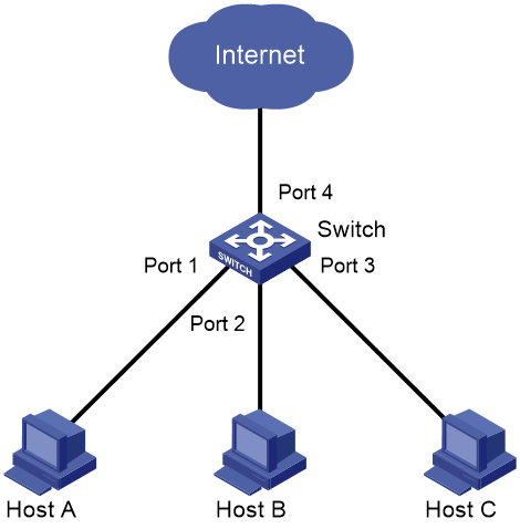
Network configuration
As shown in Figure 42, LAN users Host A, Host B, and Host C are connected to Port 1, Port 2, and Port 3 on the device, respectively. The device connects to the Internet through Port 4.
Configure the device to provide Internet access for all the hosts, and isolate them from one another.
Procedure
1. From the navigation pane, select Switch Settings > Port Isolation.
2. Configure the port isolation state, and then click OK in the dialog box that opens.
By default, port isolation is disabled.
Figure 43 Port isolation page

Figure 44 Confirming operation

Verifying the configuration
1. From the navigation pane, select Switch Settings > Port Isolation.
2. Verify that Port 1, Port 2, and Port 3 are isolated from one another at Layer 2, and Host A, Host B, and Host C cannot communicate with each other at Layer 2.
Figure 45 Port isolation information
MAC address configuration example
Network configuration
Host A at MAC address 00:0f:e2:35:dc:71 is connected to Port 1 of Device and belongs to VLAN 1. Host B at MAC address 00:0f:e2:35:ab:cd, which behaved suspiciously on the network, also belongs to VLAN 1. Configure the MAC address table as follows:
· To prevent MAC address spoofing, add a static entry for Host A in the MAC address table of Device.
· To drop all frames destined for Host B, add a blackhole MAC address entry for Host B.
Figure 46 Network diagram

Procedure
# Add a static MAC address entry with destination address 00:0f:e2:35:dc:71, outgoing interface Port 1, and VLAN ID 1.
1. From the navigation pane, select Switch Settings > Static MAC.
2. Enter MAC address 00:0f:e2:35:dc:71 and VLAN ID 1, select port 1 as the outgoing interface, and then click Add.
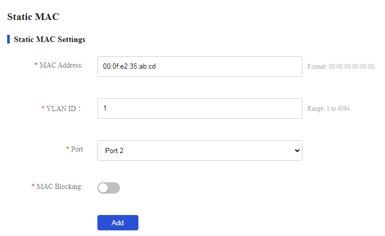
# Add a static MAC address entry with destination address 00:0f:e2:35:ab:cd, outgoing interface Port 1, and VLAN ID 1, and block the MAC address.
1. From the navigation pane, select Switch Settings > Static MAC.
2. Enter MAC address 00:0f:e2:35:ab:cd and VLAN ID 1, select port 1 as the outgoing interface, enable MAC blocking, and then click Add.
Figure 47 Static MAC address entries
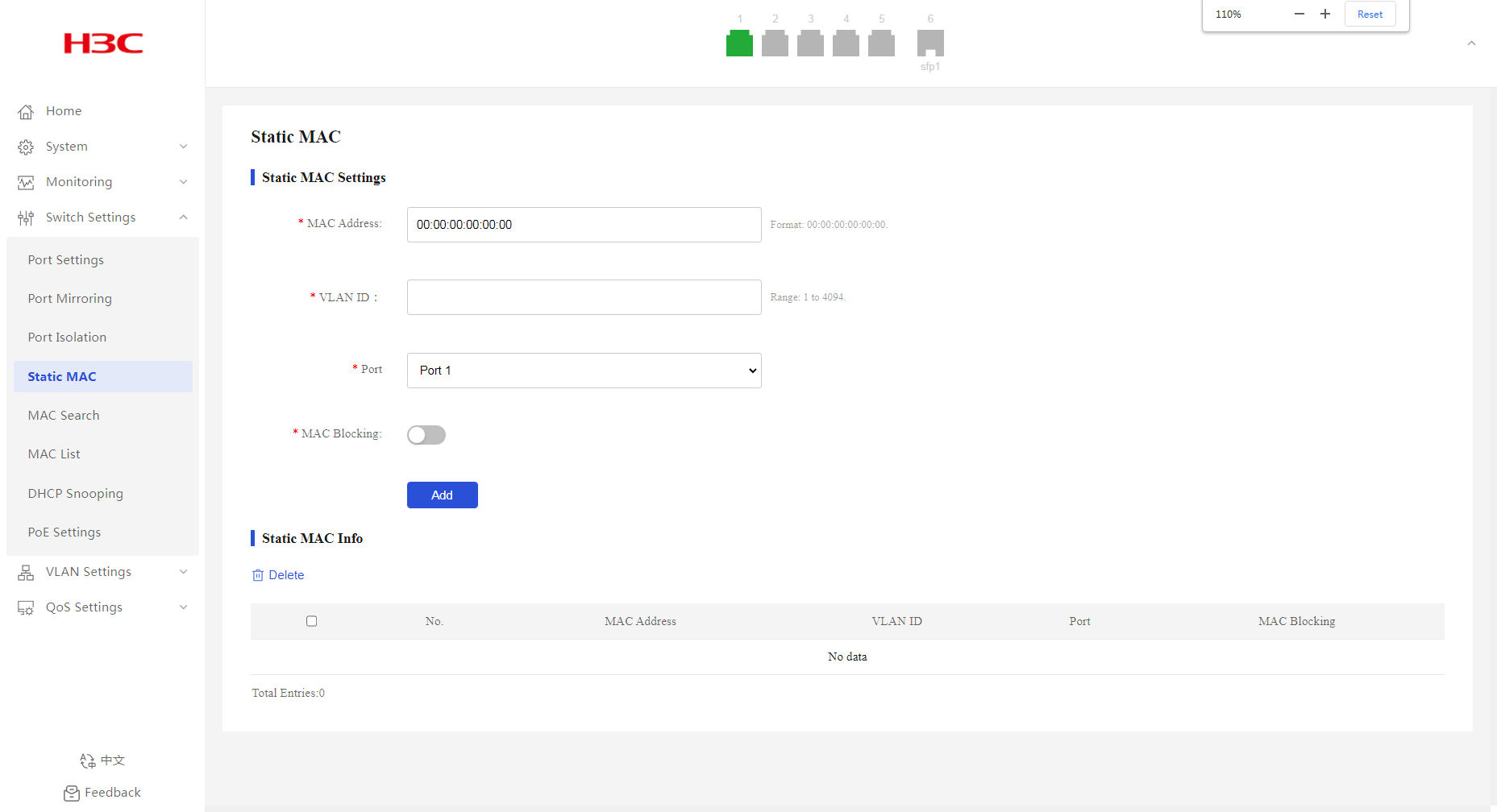
Figure 48 Adding a static MAC address entry
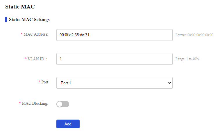
Figure 49 Adding a static MAC address entry and blocking it
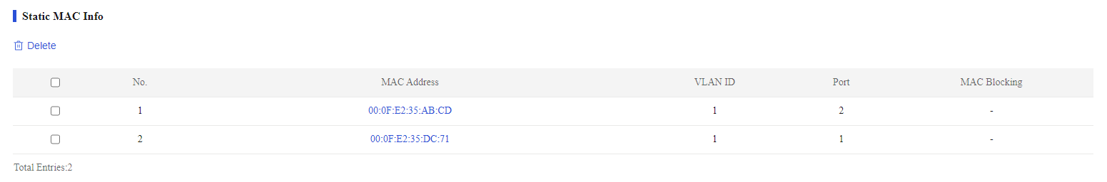
Verifying the configuration
Verify that the MAC address entries are displayed in the list.
Figure 50 Static MAC address entries
Example: Enabling DHCP snooping globally
Network configuration
Switch B is connected to the authorized DHCP server through Ethernet port 1, to the unauthorized DHCP server through Ethernet port 3, and to the DHCP client through Ethernet port 2.
Configure only the port connected to the authorized DHCP server to forward the responses from the DHCP server.
Figure 51 Network diagram

Procedure
# Enable DHCP snooping globally:
1. From the navigation pane, select Switch Settings > DHCP Snooping.
2. Enable DHCP snooping.
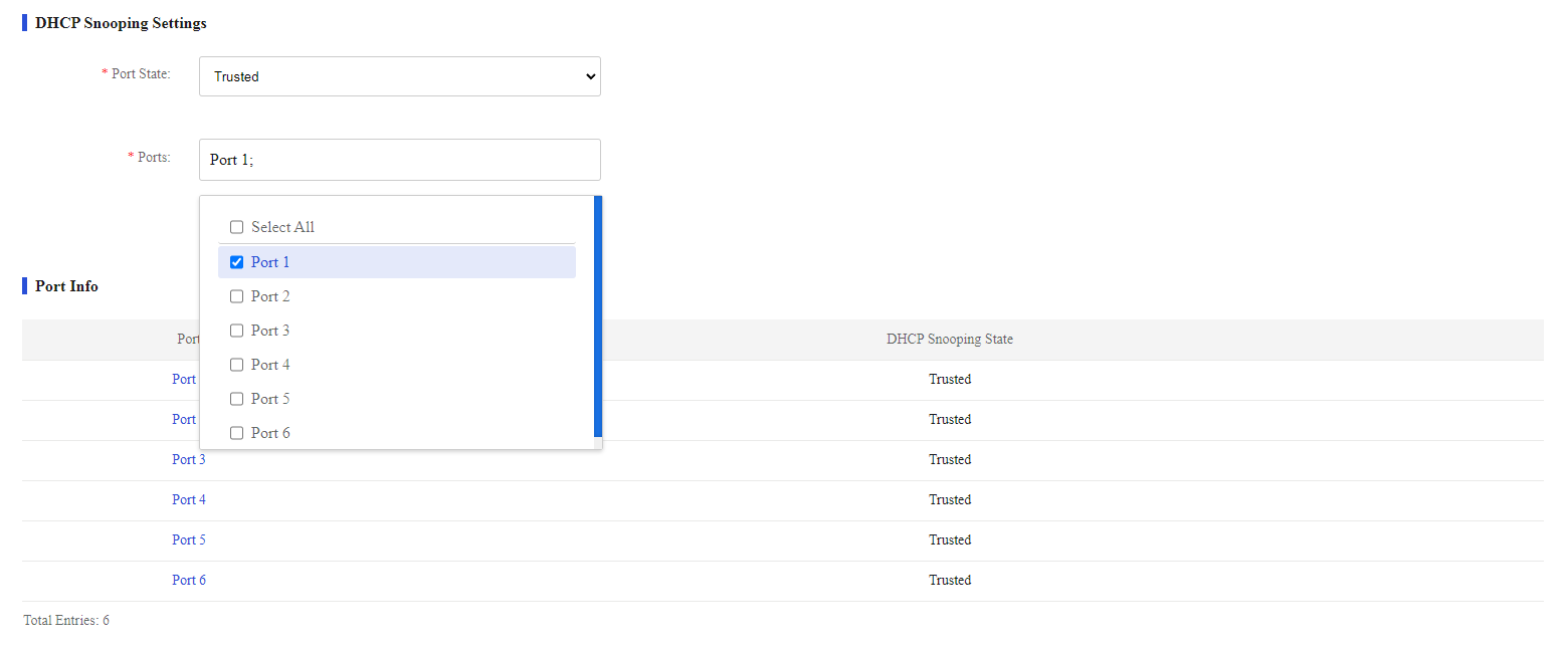
# Configure port 1 as a trusted port:
1. From the navigation pane, select Switch Settings > DHCP Snooping.
2. Select the port state to trusted.
3. Select port 1 from the port list.
4. Click Submit.
Figure 53 Configuring DHCP snooping settings
Verifying the configuration
Verify that the DHCP client can obtain an IP address and other configuration parameters only from the authorized DHCP server.
VLAN Settings
Overview
The Virtual Local Area Network (VLAN) technology divides a physical LAN into multiple logical LANs. Each VLAN is a broadcast domain. Hosts in the same VLAN can communicate with one another at Layer 2, but they are isolated from hosts in other VLANs at Layer 2.
Restrictions and guidelines
An ES4200 switch supports VLAN settings when it runs in standalone mode.
VLAN features
Overview
If you disable the VLAN feature, the device forwards received packets without processing VLAN tags.
Procedure
1. Access the VLAN members or VLAN settings page.
2. Enable or disable the VLAN feature, and then click OK in the dialog box that opens.
By default, VLAN is enabled.
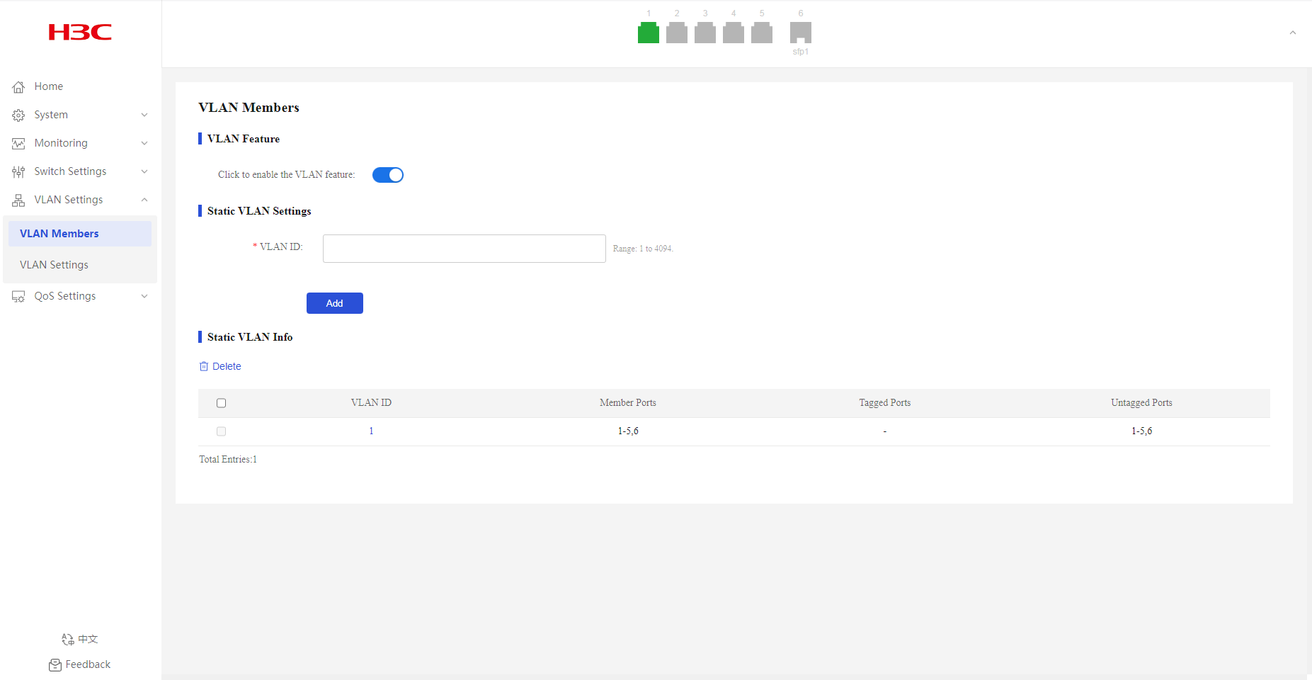
VLAN Members
Creating VLANs
1. From the navigation pane, select VLAN Settings > VLAN Members.
2. Enter the target VLAN ID, and then click Add.
By default, only system-defined VLAN 1 exists.

Deleting VLANs
1. From the navigation pane, select VLAN Settings > VLAN Members.
2. Select the VLANs to be deleted, and then click Delete. VLAN 1 cannot be deleted.
VLAN Settings
Overview
Port-based VLANs group VLAN members by port. A port forwards packets from a VLAN only after it is assigned to the VLAN.
Port link type
You can set the link type of a port to access or trunk. The port link type determines whether the port can be assigned to multiple VLANs. The link types use the following VLAN tag handling methods:
· Access—An access port can forward packets only from one VLAN and send these packets untagged. An access port is typically used in the following conditions:
¡ Connecting to a terminal device that does not support VLAN packets.
¡ In scenarios that do not distinguish VLANs.
· Trunk—A trunk port can forward packets from multiple VLANs. Except packets from the port VLAN ID (PVID), packets sent out of a trunk port are VLAN-tagged. Ports connecting network devices are typically configured as trunk ports.
PVID
The PVID (native VLAN) identifies the default VLAN of a port. Untagged packets received on a port are considered as the packets from the port PVID.
An access port can join only one VLAN. The VLAN to which the access port belongs is the PVID of the port. A trunk port supports multiple VLANs and the PVID configuration.
How ports of different link types handle frames
|
Actions |
Access |
Trunk |
|
In the inbound direction for an untagged frame |
Tags the frame with the PVID tag. |
· If the PVID is permitted on the port, tags the frame with the PVID tag. · If not, drops the frame. |
|
In the inbound direction for a tagged frame |
· Receives the frame if its VLAN ID is the same as the PVID. · Drops the frame if its VLAN ID is different from the PVID. |
· Receives the frame if its VLAN is permitted on the port. · Drops the frame if its VLAN is not permitted on the port. |
|
In the outbound direction |
Removes the VLAN tag and sends the frame. |
· Removes the tag and sends the frame if the frame carries the PVID tag and the port belongs to the PVID. · Sends the frame without removing the tag if its VLAN is carried on the port but is different from the PVID. |
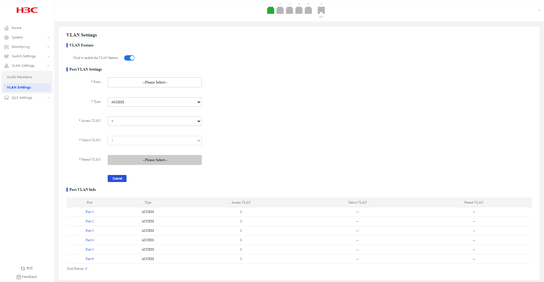
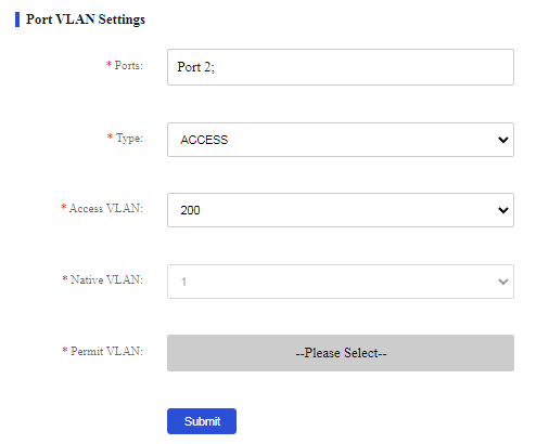
Configuring port VLAN settings
Configuring access ports and specifying an access VLAN
1. From the navigation pane, select VLAN Settings > VLAN Settings.
2. Select the target ports from the port list.
3. Select the access link type. The default link type is access.
4. Select an access VLAN. By default, all access ports belong to VLAN 1.
5. Click Submit.
Figure 55 Configuring access ports and specifying an access VLAN
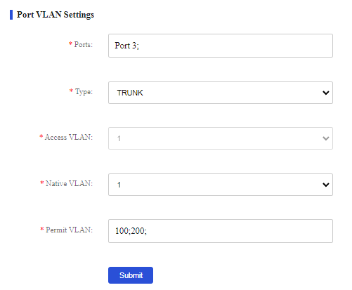
Configuring trunk ports and specifying PVID and permit VLAN
1. From the navigation pane, select VLAN Settings > VLAN Settings.
2. Select the target ports from the port list.
3. Select the trunk link type. The default link type is access.
4. Select native and permit VLANs.
5. Click Submit.
Displaying port VLAN information
1. From the navigation pane, select VLAN Settings > VLAN Settings.
2. You can view port VLAN information in the Port VLAN Info area.
Configuration example
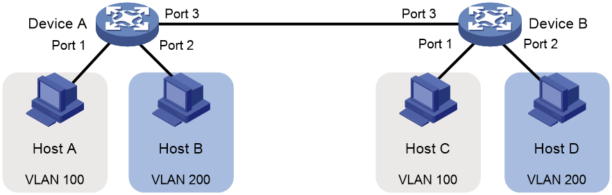
Network configuration
· Host A and Host C belong to Department A but access the company network through different devices. Host B and Host D belong to Department B and access the company network through different devices.
· To ensure communication security and avoid flooding broadcast packets, use VLANs to isolate Layer 2 traffic of different departments. Configure department A to use VLAN 100, and configure department B to use VLAN 200.
Figure 56 Network diagram
Procedure
Configuring Device A
# Create VLAN 100 and VLAN 200:
1. From the navigation pane, select VLAN Settings > VLAN Members.
2. Enter VLAN ID 100, and then click Add.
3. Enter VLAN ID 200, and then click Add.
# Configure port VLANs:
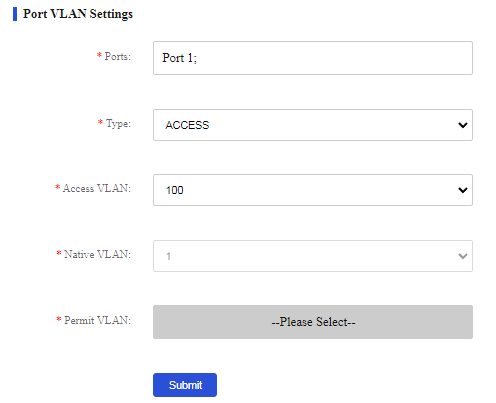
1. From the navigation pane, select VLAN Settings > VLAN Settings.
2. Assign port 1 to VLAN 100:
a. Select port 1 from the port list.
b. Select the access link type.
c. Select VLAN 100 from the access VLAN list.
d. Click Submit.
Figure 58 Configuring VLAN settings for port 1
3. Assign port 2 to VLAN 200:
a. Select port 2 from the port list.
b. Select the access link type.
c. Select VLAN 200 from the access VLAN list.
d. Click Submit.
Figure 59 Configuring VLAN settings for port 2
4. Configure port 3 as a trunk port and assign it to VLANs 100 and 200, so that Device A can send packets from VLAN 100 and VLAN 200 to Device B.
a. Select port 3 from the port list.
b. Select the trunk link type.
c. Select VLAN 1 from the native VLAN list.
d. Select VLANs 100 and 200 from the permit VLAN list.
e. Click Submit.
Figure 60 Configuring VLAN settings for port 3
Configuring Device B
Configure Device B in the same way you configure Device A.
Configuring the hosts
Verifying the configuration
Verify that Host A and Host C can successfully ping each other, and they cannot ping Host B or Host D. Verify that Host B and Host D can successfully ping each other, and they cannot ping Host A or Host C.
QoS Settings
Port Rate Limit
Overview
This feature allows you to limit the total packet rate.
Configuring port bandwidth settings
1. From the navigation pane, select QoS Settings > Port Rate Limit.
2. Select the target ports from the port list.
3. Select Tx or Rx from the type list.
4. Select a port rate limit state.
By default, port rate limit is disabled.
5. If you enable port rate limit, enter the rate limit.
6. Click Submit.
Figure 61 Configuring port bandwidth settings
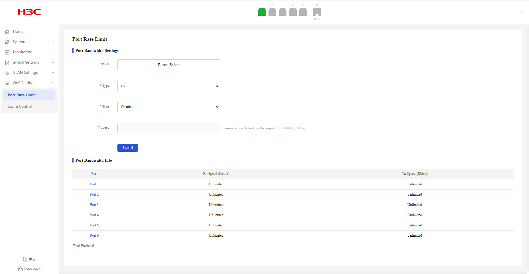
Displaying port bandwidth information
1. From the navigation pane, select QoS Settings > Port Rate Limit.
2. You can view port bandwidth information in the Port Bandwidth Info area.
Storm Control
Overview
After you configure broadcast/unknown unicast/unknown multicast storm control on an interface, if the broadcast/unknown unicast/unknown multicast traffic exceeds the specified threshold, the system discards the excessive traffic.
After packets of a protocol are added to the storm suppression and storm control allowlist, storm suppression and storm control do not take effect on packets of the protocol.
Configuring storm control
1. From the navigation pane, select QoS Settings > Storm Control.
2. Select a traffic type from the Storm Type list.
3. Select the target ports.
4. Enable or disable storm control. By default, storm control is disabled.
5. Set the suppression threshold in the Speed field.
6. Click Submit.
Figure 62 Configuring storm control
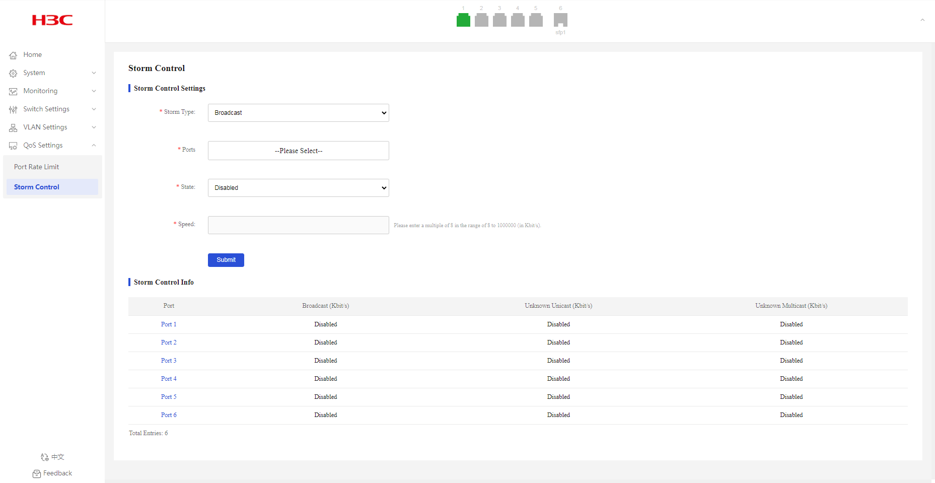
Displaying storm control information
1. From the navigation pane, select QoS Settings > Storm Control.
2. You can view storm control information in the Storm Control Info area.
Troubleshooting
A fiber port fails to come up
Symptom
A fiber port fails to come up.
Troubleshooting flowchart
Figure 63 Troubleshooting link up failure on a fiber port
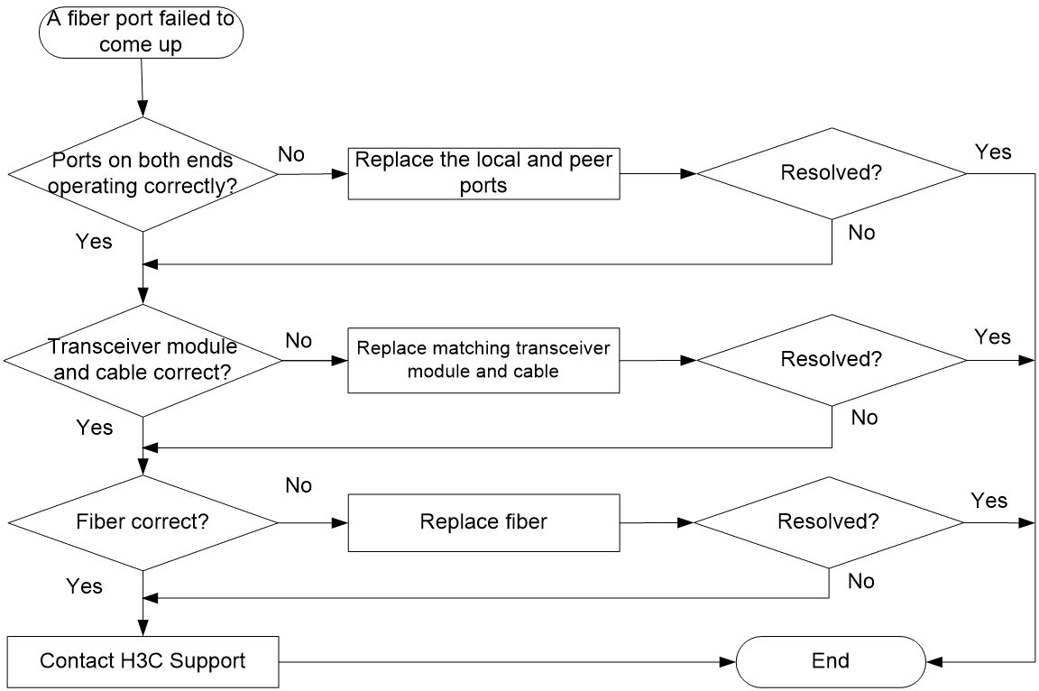
Solution
Verifying that the ports at both ends are operating correctly
Use a transceiver module and a fiber to connect the port to another port on the local end. Identify whether the port can come up:
· If the port can come up, you can determine that the peer port fails. Replace the peer port with a new port operating correctly.
· If the port cannot come up, you can determine that the local port fails. Replace the local port with a new port operating correctly.
Verifying that the transceiver module and cable are operating correctly
If the transceiver module is not operating correctly, replace it with a H3C transceiver module that matches the fiber port. Perform the following tasks to troubleshoot the transceiver module:
1. Verify that the wavelength and transmission distance of the local transceiver module are consistent with the wavelength and transmission distance of the peer transceiver module.
2. Use an optical power meter to verify that the Tx power and Rx power of the transceiver module are stable and are within the correct range.
For more information about transceiver modules and cables, see the installation guide.
Verifying that the fiber is operating correctly
Verify that the fiber matches the transceiver module. If they do not match, replace the fiber with a new one that matches the transceiver module. For more information about fibers, see the installation guide.
Contacting H3C Support
If the issue persists after the above procedures, collect the fault information, and contact H3C Support.
A copper port fails to come up
Symptom
A copper port fails to come up.
Troubleshooting flowchart
Figure 64 Troubleshooting link up failure on a copper port
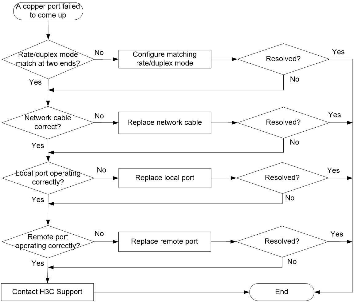
Solution
Verifying that the local and remote ports are consistent in rate and duplex mode
To view port rate and duplex mode information, see "Port Info." If the local and remote ports are inconsistent in rate and duplex mode, edit the settings. For procedures, see "Configuring port settings."
Verifying that the network cable is in good condition
Replace the network cable with a new one to verify that the network cable is in good condition.
Verifying that the local port is operating correctly
Replace the local port with a new one to verify that the local port is operating correctly.
Verifying that the peer port is operating correctly
Replace the peer port with a new one to verify that the peer port is operating correctly.
Contacting H3C Support
If the issue persists after the above procedures, contact H3C Support.
PoE power supply anomaly
Symptom
The PoE device cannot supply power correctly.
Troubleshooting flowchart
Figure 65 Troubleshooting PoE power supply anomaly
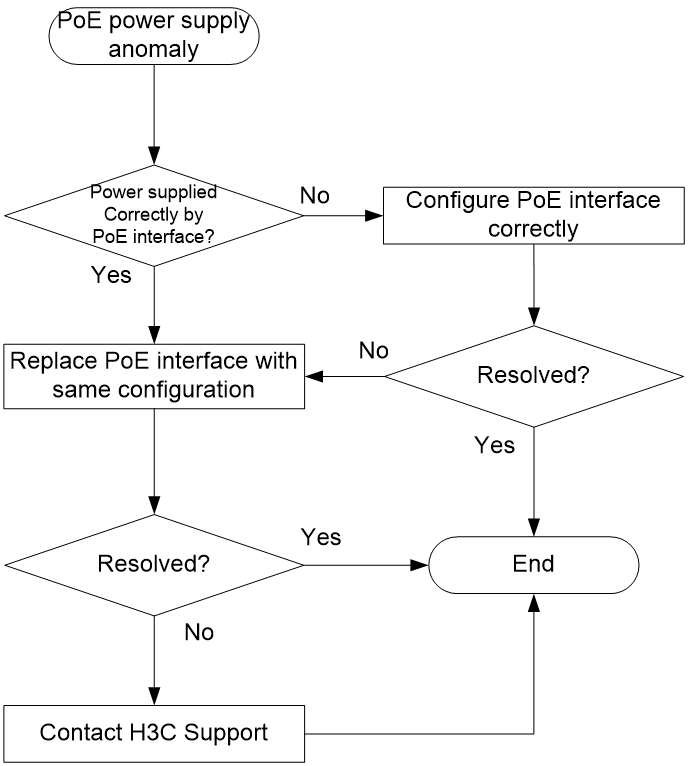
Solution
1. Verify that the PoE settings are correct. For more information, see "PoE."
If the PoE power is close to or reach the maximum power, disable unnecessary PoE port features or use PoE power with higher-wattage supply.
2. Verify that the PoE port is operating correctly.
Replace the PoE port with a new one to verify that the PoE port is operating correctly. If the PoE port is not operating correctly, replace and port and send the fault information to Technical Support.
3. If the issue persists after the above procedures, collect the fault information, and contact H3C Support.
Error packets on a port
Symptom
Error packets were collected on a port.
Troubleshooting flowchart
Figure 66 Troubleshooting error packets on a port
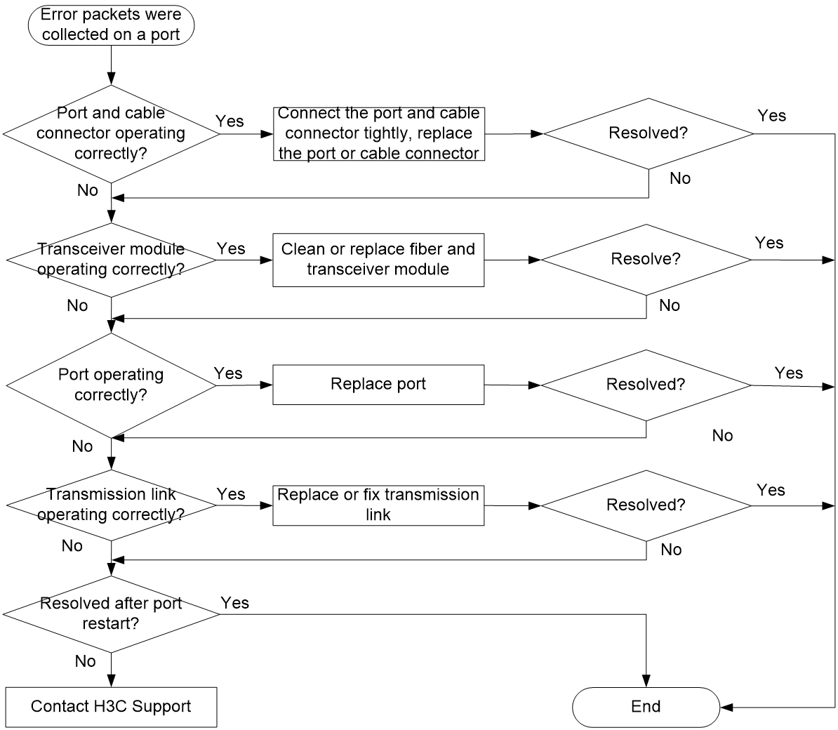
Solution
1. Verify that the port and cable connector are operating correctly.
¡ Verify that the port and cable connector are connected tightly.
¡ Inspect the port for any abnormalities, such as foreign objects inside the port, bent pins, or malformation. If abnormalities are found, replace the port or transceiver module.
¡ Verify that the cable connector is not damaged. In case of any damages, replace it.
2. Verify that the transceiver module is operating correctly.
Use a fiber to connect the Tx and Rx ends of the port's transceiver module, and then refresh the traffic statistics page to see if the number of error packets increase. If the number increases, the transceiver module is not operating correctly.
3. Replace the port with a new one to verify that the port is operating correctly.
Replace the port with a new one to verify that the port is operating correctly. If the port is not operating correctly, replace the port and send the fault information to H3C Support.
4. Verify that the transmission link is operating correctly.
¡ Use a tester to test the transmission link. Poor link quality or excessive optical signal attenuation can lead to packet errors during transmission.
¡ Verify that the devices on the transmission link (including the fiber converter, adapter cable, and transmission device) are operating correctly. In case of any failures, replace the devices or link.
5. Access the details page of the failed port, restart the link, and verify whether the port recovers.
6. If the issue persists after the above procedures, collect the fault information, and contact H3C Support.
