- Table of Contents
-
- 15-BRAS Services Configuration Guide
- 00-Preface
- 01-AAA configuration
- 02-ANCP configuration
- 03-PPP configuration
- 04-Value-added services configuration
- 05-DHCP configuration
- 06-DHCPv6 configuration
- 07-User profile configuration
- 08-Connection limit configuration
- 09-L2TP configuration
- 10-PPPoE configuration
- 11-IPoE configuration
- 12-UCM configuration
- Related Documents
-
| Title | Size | Download |
|---|---|---|
| 12-UCM configuration | 179.16 KB |
Contents
Basic UCM functional structure
Basic UCM user access procedure
Restrictions and guidelines: UCM configuration
Configuring features specific to BRAS access users
Configuring the interface-down policy for online BRAS users on an interface
Configuring the maximum number of access users allowed on an interface
Setting the traffic accounting frequency mode for online BRAS users
Enabling logging for access users
Setting the online access user session count alarm thresholds on the device
Configuring the per-slot user count trap feature
Configuring the user online failure threshold alarm function
Configuring the packet loss ratio alarm for access user detection packets
Configuring auto user logout before BRAS reboot
Configuring the data backup mode for the BRAS service module
Configuring the NAS-Port-Type attribute for an interface
Configuring access user common management
Configuring service tracing objects
Display and maintenance commands for UCM
Configuring UCM
About UCM
User Connection Management (UCM) is a unified user management component. UCM centralizedly manages connections of various access users to simplify user management and O&M.
Basic UCM functional structure
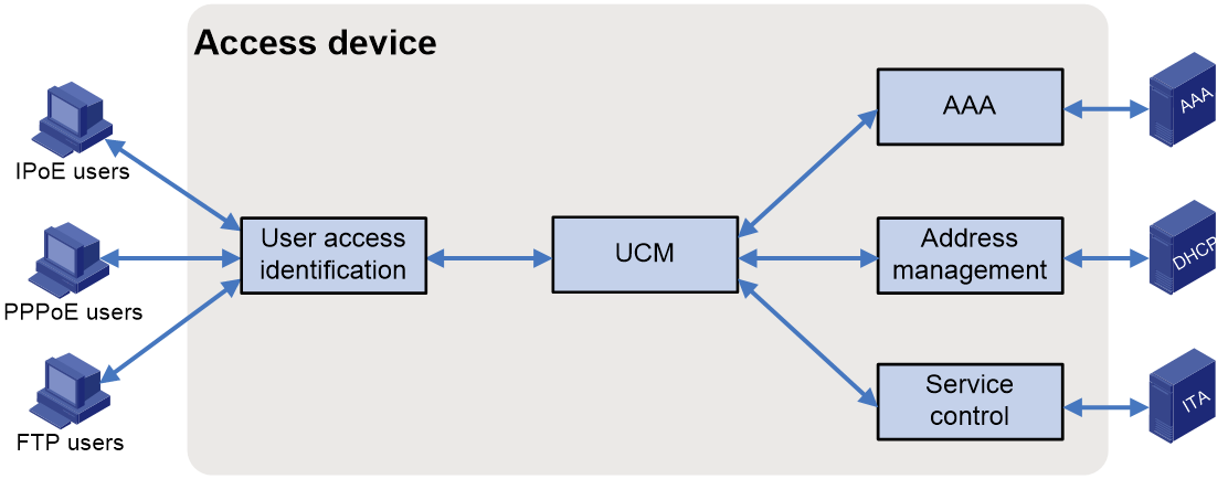
As shown in Figure 1, the access user login procedure involves five components. UCM is the bridge among the other four components. UCM coordinates the interoperation among these components and assists user connection setup, maintenance, and removal.
Figure 1 Basic UCM functional structure
This chapter describes only the basic functions of these components. For more information, see the documents for these components.
The basic functions of these components are as follows:
· User access identification component—Identifies and processes various access protocol packets of users, and obtains the usernames, passwords, and physical locations of users in the user authentication procedure to provide information and security for valid user access.
· UCM component—Acts as a bridge among the other four components to coordinate the interoperation among these components and assist user connection setup, maintenance, and removal.
· AAA component—Performs authentication, authorization, and accounting for users.
· Address management component—Allocates IP addresses to access users, and ensure proper use of IP resources through unified IP address management.
· Service control component—Control the access privilege, bandwidth, and QoS policies for the basic services and value-added services of access users.
UCM user types
Depending on application scenarios of users, users managed by UCM include the following types:
· Device management users—Log in to devices and configure and monitor devices. These users can provide FTP, HTTP, HTTPS, and Telnet services.
· Network access users—Access networks through devices and access network resources. These uses can provide IPoE, PPPoE, and L2TP services. Among these services, the IPoE, PPPoE, and L2TP services are uniformly called Broadband Remote Access Server (BRAS) features.
Basic UCM user access procedure
This chapter describes only the basic user access and authentication procedures. For more information, see the documents for related protocol modules.
The basic UCM user access procedure is as follows:
1. The user identification component obtains authentication information.
After the user identification component receives connection requests from a user endpoint, the component obtains the username, password, and physical location from the packets and sends the information to UCM for authentication.
2. UCM requests authentication.
UCM determines whether to allow the user to access based on conditions such as access restrictions. If the user is allowed to access, UCM sends authentication information to the AAA component.
3. AAA authenticates and authorizes the user.
The AAA component authenticates and authorizes the user according to the AAA scheme and returns the authentication result and authorization information to UCM.
4. UCM requests IP address allocation.
If the user successfully passes authentication, UCM requests IP addresses from the address management component.
5. The address management component allocates IP addresses.
According to the user information, the address management component allocates IP addresses and returns the allocation result to UCM. To allocate remote IP addresses, the address management component must connect to an external DHCP server.
6. UCM allows the user to come online.
UCM returns the authentication result and the allocated IP addresses to the access identification component. The access identification allows the user to come online.
7. The AAA component and the service control component perform accounting and control.
After the user comes online, the AAA component and the service control component together control accounting, bandwidth limit, and QoS for basic services and value-added services of the user.
Restrictions and guidelines: UCM configuration
Telnet users that do not use AAA authentication are not managed by UCM.
On an interface with online UCM users, you cannot configure any of the following features:
· Switching the link mode of an interface (port link-mode). For more information, see Ethernet interface configuration in Interface Configuration Guide.
· Configuring an interface as a reflector port for a remote source mirroring group (mirroring-group reflect-port). For more information, see mirroring configuration in Network Management and Monitoring Configuration Guide.
· Assigning an interface to an aggregation group (port link-aggregation group). For more information, see Ethernet link aggregation configuration in Layer 2—LAN Switching Configuration Guide.
UCM tasks at a glance
To configure UCM, perform the following tasks:
1. Configuring features specific to BRAS access users
¡ Configuring the interface-down policy for online BRAS users on an interface
¡ Configuring the maximum number of access users allowed on an interface
¡ Setting the traffic accounting frequency mode for online BRAS users
¡ Enabling logging for access users
¡ Setting the online access user session count alarm thresholds on the device
¡ Configuring the per-slot user count trap feature
¡ Configuring the user online failure threshold alarm function
¡ Configuring the packet loss ratio alarm for access user detection packets
¡ Configuring auto user logout before BRAS reboot
¡ Configuring the data backup mode for the BRAS service module
¡ Configuring the NAS-Port-Type attribute for an interface
2. Configuring access user common management
¡ Configuring service tracing objects
Prerequisites
UCM simplifies user management through coordinating the interoperation among AAA and address management components and assisting user connection setup, maintenance, and removal. For UCM and the other components to cooperate, complete the following tasks before configuring UCM:
· To configure DHCP packet initiation, you must first install and configure DHCP servers. If this network is a DHCP relay agent network, you must enable the DHCP relay agent on the BRAS.
· To perform authentication through a remote RADIUS server, perform the following tasks:
a. Make sure the RADIUS server is successfully installed.
b. Configured and configure the corresponding usernames and passwords on the RADIUS server.
c. Configure the RADIUS client on the BRAS.
· To perform security check and authorization through a remote security server, perform the following tasks:
a. Configure the security policies on the H3C IMC security policy server.
b. Specify the security policy server IP address on the BRAS.
For more information about configuring the RADIUS client and configuring the security policy server, see AAA configuration in BRAS Services Configuration Guide.
· To perform authentication through the local device, you must configure related local users and their attributes on the BRAS. For information about configuring local users, see AAA configuration in BRAS Services Configuration Guide.
· Make sure users, the BRAS, and servers can reach each other through routes.
· To configure a CUPS network, first plan which devices are UPs and which devices are CPs.
Configuring features specific to BRAS access users
Configuring the interface-down policy for online BRAS users on an interface
About this task
By default, when an interface goes down, the users are forced to go offline. When the interface recovers from down to up, these users must perform authentication again to come online. To prevent users from frequently coming online and going offline because the interface frequently comes up and goes down, you can use this feature to keep users online after the interface goes down.
Restrictions and guidelines
This feature takes effect only on PPPoE and IPoE access users.
Procedure
1. Enter system view.
system-view
2. Enter interface view.
interface interface-type interface-number
3. Configuring the interface-down policy for online BRAS users on an interface
user-policy interface-down online [ no-user-detect ]
By default, BRAS users on an interface are forced to go offline after the interface goes down.
When you configure an interface to keep the users online after the interface goes down, to prevent users from being logged out because the users fail online detection during the period the interface recovers from down to up, specify the no-user-detect keyword.
Configuring the maximum number of access users allowed on an interface
Restrictions and guidelines
If the configured limit is smaller than the number of existing users on an interface (or VLANs on an interface), the configuration succeeds and the existing users are not affected. However, new users cannot access on the interface (or VLANs on the interface).
When this command is executed together with the pppoe-server session-limit per-vlan command and the access-limit command in an ISP domain, the three commands all take effect. The three commands control the number of users on the interface (or VLANs on the interface) in different perspectives, and the number of users is controlled by all the three commands. A new PPPoE user can access only when none of these limits is reached.
When this command is executed together with the access-limit command in an ISP domain, the two commands both take effect. The two commands control the number of BRAS users on the interface (or VLANs on the interface) in different perspectives, and the number of BRAS users is controlled by both commands. A new BRAS user can access only when neither limit is reached.
Procedure
1. Enter system view.
system-view
2. Enter interface view.
interface interface-type interface-number
3. Configure the maximum number of access users allowed on the interface.
access-limit user-number [ start-vlan start-vlan [ end-vlan end-vlan ] [ qinq qinq-vlan ] ]
By default, the maximum number of access users on an interface is not limited.
Setting the traffic accounting frequency mode for online BRAS users
About this task
Perform this task to adjust the frequency at which the device updates the online BRAS user statistics as needed. The following traffic accounting frequency modes are supported:
· fast—Fast mode. For high accuracy of the BRAS user traffic statistics, specify this keyword.
· normal—Normal mode. For medium accuracy of the BRAS user traffic statistics, specify this keyword.
· slow—Slow mode. For low accuracy of the BRAS user traffic statistics, specify this keyword.
Procedure
1. Enter system view.
system-view
2. Set the traffic accounting frequency mode for online BRAS users.
flow-statistics frequency { fast | normal | slow }
By default, the traffic accounting frequency mode for online BRAS users is normal.
Enabling logging for access users
About this task
To meet the maintenance requirements of network administrators, this feature enables the device to generate logs and send them to the information center. Logs are generated after a user comes online successfully, fails to come online, normally goes offline, or abnormally goes offline. A log entry contains information such as the username, IP address, interface name, inner VLAN, outer VLAN, MAC address, and failure causes. For information about the log destination and output rule configuration in the information center, see Network Management and Monitoring Configuration Guide.
Restrictions and guidelines
As a best practice, disable this feature to prevent excessive log output.
Procedure
1. Enter system view.
system-view
2. Enable logging for access users.
access-user log enable [ abnormal-logout | failed-login | normal-logout | successful-login ] *
By default, logging for BRAS access users is disabled.
Setting the online access user session count alarm thresholds on the device
About this task
The online access user session count on the device is the total number of online IPoE sessions, PPPoE sessions, and L2TP sessions on the device.
You can use this feature to set the upper alarm threshold and lower alarm threshold for the online access user session count. When the online access user session count exceeds the upper alarm threshold or drops below the lower threshold, an alarm is triggered automatically. Then, the administrator can promptly know the online user conditions of the network. To view the total number of access users, use the display access-user command.
The user session count alarm function counts only user sessions that occupy session resources. In the current software version, only the following sessions occupy session resources:
· The following IPoE sessions:
¡ Sessions of individual access users
¡ Sessions of interface-leased users
¡ Sessions of interface-leased subusers
¡ Sessions of subnet-leased users
¡ Sessions of subnet-leased subusers
¡ Sessions of L2VPN-leased users
· PPPoE sessions
· L2TP sessions
Either a single-stack user or dual-stack user occupies one session resource.
Suppose the maximum number of online access user sessions allowed on the device is a, the upper alarm threshold is b, and the lower alarm threshold is c. The following rules apply:
· When the online access user session count exceeds a×b or drops below a×c, the corresponding alarm information is output.
· When the online access user session count returns between the upper alarm threshold and lower alarm threshold, the alarm clearing information is output.
In some special cases, the online access user session count frequently changes in the critical range, which causes frequent output of alarm information and alarm clearing information. To avoid this problem, the system introduces a buffer area when the online access user session count recovers from the upper or lower threshold. The buffer area size is 10% of the difference between the upper threshold and the lower threshold. Suppose the buffer area size is d. Then, d=a×(b-c)÷10. When the online access user session count drops below a×b-d or exceeds a×c+d, the alarm information is output.
For example, suppose a is 1000, b is 80%, and c is 20%. Then, d= a×(b-c)÷10=1000×(80%-20%)÷10=1000×60%÷10=600÷10=60.
· When the online access user session count exceeds the upper threshold a×b=1000×80%=800, the upper threshold alarm is output. When the online access user session count restores to be smaller than a×b-d=800-60=740, the alarm clearing information is output.
· When the online access user session count drops below the lower threshold a×c=1000×20%=200, the lower threshold alarm is output. When the online access user session count restores to be greater than a×c+d=200+60=260, the alarm clearing information is output.
The upper threshold alarm information output and the alarm clearing information output both contain logs and traps.
· The generated log messages by the device will be sent to the information center. The information center configuration specifies the log message sending rule and destination. For more information about the information center, see Network Management and Monitoring Configuration Guide.
· For traps to be correctly sent to the NMS host, you must execute the snmp-agent trap enable user-warning-threshold command in addition to configuring the SNMP alarm feature correctly. For more information about SNMP alarms, see SNMP configuration in Network Management and Monitoring Guide.
Restrictions and guidelines
The upper alarm threshold must be greater than the lower alarm threshold.
Procedure
1. Enter system view.
system-view
2. Configure the upper and lower online access user session count alarm thresholds.
access-user session-threshold { lower-limit lower-limit-value | upper-limit upper-limit-value }
By default, the upper online access user session count alarm threshold is 100, and the lower online access user session count alarm threshold is 0.
3. Enable the device-level user count trap feature.
snmp-agent trap enable user-warning-threshold
By default, the device-level user count trap feature is disabled.
Configuring the per-slot user count trap feature
About this task
You can use this feature to set the per-slot user count alarm threshold. When the user count on a slot exceeds the threshold, an alarm is triggered automatically. Then, the administrator can promptly know the online user conditions of the network.
This feature counts only the number of IPoE users, PPPoE users, and L2TP users.
· A dual-stack PPPoE user is counted as one user.
· A dual-stack IPoE user is counted as one user.
· For IPoE leased users, one interface-leased user is counted as one user, and one subnet-leased user is counted as one user.
· For IPoE leased subusers, one subuser is counted as one user.
· L2TP users on LACs are counted in the same way as PPPoE users are counted. L2TP users on LNSs are not counted.
Suppose the per-slot maximum user count allowed is a and the per-slot user count alarm threshold is b. The following rules apply:
· When the user count on a slot exceeds a×b, the alarm information is output.
· When the user count on a slot drops within the normal range, the alarm clearing information is output.
In some special cases, the user count on a slot frequently changes in the critical range, which causes frequent output of alarm information and alarm clearing information. To avoid this problem, the system introduces a buffer area when the user count on a slot drops below the threshold. The buffer area size is 10% of the threshold set. Suppose the buffer area size is c. Then, c=a×b÷10. When the user count on a slot drops below a×b-c, the alarm clearing information is output.
For example, suppose a is 1000 and b is 80%. Then, c= a×b÷10=1000×80%÷10=80.
· When the user count on a slot exceeds a×b=1000×80%=800, the alarm information is output.
· When the user count on a slot drops below a×b-c=800-80=720, the alarm clearing information is output.
The upper threshold alarm information output and the alarm clearing information output both contain logs and traps.
· The generated log messages by the device will be sent to the information center. The information center configuration specifies the log message sending rule and destination. For more information about the information center, see Network Management and Monitoring Configuration Guide.
· For traps to be correctly sent to the NMS host, you must execute the snmp-agent trap enable user-warning-threshold command in addition to configuring the SNMP alarm feature correctly. For more information about SNMP alarms, see SNMP configuration in Network Management and Monitoring Guide.
Setting the per-slot user count alarm threshold
1. Enter system view.
system-view
2. Set the per-slot user count alarm threshold.
slot-user-warning-threshold threshold-value
By default, the per-slot user count alarm threshold is 100.
3. Enable the per-slot user count trap feature.
snmp-agent trap enable slot-user-warning-threshold
By default, the per-slot user count trap feature is disabled.
Configuring the user online failure threshold alarm function
About this task
With the user online failure threshold alarm function enabled, when the number of user online failures within an alarm detection interval exceeds the specified threshold, an alarm is automatically triggered. Then, the administrator can promptly learn the user online failure conditions on the live network. An administrator can execute the display aaa online-fail-record command to view user online failure records.
The alarm information output contains logs and traps.
· The generated log messages by the device will be sent to the information center. The information center configuration specifies the log message sending rule and destination. For more information about the information center, see Network Management and Monitoring Configuration Guide.
· To send the traps to an NMS correctly, you must also configure SNMP correctly as described in Network Management and Monitoring Configuration Guide. For more information about SNMP alarms, see SNMP configuration in Network Management and Monitoring Guide.
The total number of access user online failures refers to the sum of IPoE user, PPPoE user, and L2TP user online failures on the whole device.
The total number of access user online events refers to the sum of IPoE user, PPPoE user, and L2TP user online failures and online successes on the whole device.
If a single user comes online successfully or fails to come online for multiple times, each online success or failure is counted in the total number of online successes or failure.
When the device calculates the number of online events of a user, the device uniquely identifies a user by the MAC address, inner VLAN, and outer VLAN.
· For a dual-stack user, only if the user successfully comes online in one protocol stack, the user is considered as coming online successfully. A dual-stack user is considered failing to come online only when the user fails to come online in both protocol stacks.
· For an IPoE leased user, the online events of the main user and the online events of the subusers are separately counted.
Procedure
1. Enter system view.
system-view
2. Enable the user online failure threshold alarm function.
access-user online-fail-warning threshold threshold-value period period-value
By default, the user online failure threshold alarm function is disabled.
Configuring the packet loss ratio alarm for access user detection packets
About this task
After the online user detection feature is enabled, the device will automatically create a 30-second timer. The timer will be reset after expiration. After the packet loss ratio alarm is enabled for access user detection packets, an alarm will be automatically triggered in either of the following conditions:
· The packet loss ratio calculated exceeds the specified alarm threshold when the 30-second timer expires continuously for three times, and the number of packets sent within each 30-second timer exceeds 50.
· The packet loss ratio calculated within the last 30 seconds when the 30-second timer expires restores to the normal range (equal to or less than the specified alarm threshold) after an alarm is output.
In this way, the administrator can timely learn the packet loss conditions of user detection packets on the live network.
In this function, the packet loss ratio of detection packets refers to the ratio of dropped packets (sent packets - received packets) to all detection packets within the 30-second timer on a detected interface. The formula is as follows: the packet loss ratio = (sent packets - received packet)/sent packets. If you execute the display access-user user-detect packet-loss-ratio or display ppp keepalive packet-loss-ratio command at a time point within a 30-second timer, this command displays the packet loss ratio statistics collected at the specified time point within the 30-second timer. For example, if you execute this display command at the 10th second within a 30-second timer, this command displays the packet loss ratio statistics collected within the 10 seconds.
The alarm information output contains only logs. The generated log messages by the device will be sent to the information center. The information center configuration specifies the log message sending rule and destination. For more information about the information center, see Network Management and Monitoring Configuration Guide.
Restrictions and guidelines
This feature applies to only IPoE users, PPPoE users, and L2TP users.
Procedure
1. Enter system view.
system-view
2. Enable the packet loss ratio alarm for access user detection packets.
access-user user-detect packet-loss-ratio-threshold threshold-value
By default, the packet loss ratio alarm is disabled for user detection packets.
Configuring auto user logout before BRAS reboot
About this task
By default, if devices are rebooted as planned or slots are separately rebooted when devices are upgraded, the devices or slots will not actively send accounting stop packets to the AAA server during the reboot process. During the reboot process, the devices will log out users, but the AAA server cannot sense the logout events and still considers the users online. Within a short period of time after the devices or slots are rebooted, the online users before reboot cannot log in again because the AAA server still considers them as online.
To resolve this issue, enable the feature of auto user logout before BRAS reboot. With this feature enabled, when the reboot command is executed to reboot a device or slot, the device first forbids new users from coming online, and logs out all online users or online users on the slot to be rebooted. When users are logged out, the device will actively send accounting stop packets to the AAA server. After these users are logged out, the device or slot will be rebooted.
Restrictions and guidelines
The bras auto-cut-user before-reboot command is not saved in the configuration file. After the device is rebooted, to use the feature of auto user logout before BRAS reboot again, you must execute this command again. If only slots are rebooted but the device is not rebooted, you do not need to execute this command. In this case, this command takes effect on each slot reboot.
When a slot is restarted, this feature takes effect only on users coming online through physical interfaces in the slot.
If you execute the reboot command with the force keyword specified, the feature of auto user logout before BRAS reboot does not take effect.
Procedure
1. Enter system view.
system-view
2. Enable auto user logout before BRAS reboot.
bras auto-cut-user before-reboot
By default, the feature of auto user logout before BRAS reboot is disabled.
Configuring the data backup mode for the BRAS service module
About this task
In non-realtime mode, the BRAS service module does not back up the running data to the running database in real time and the following rules apply:
· To avoid data loss when the BRAS service module process is normally restarted (for example, by using the process restart command), the BRAS service module will back up the running data of the module to the running database before the process is restarted.
· When the BRAS service module process on the active MPU is abnormal, the data of the BRAS service module on the current active MPU will be lost. The device determines whether to forcibly reboot the active MPU according to whether the auto-reboot-board keyword is specified.
Restrictions and guidelines
Active/standby MPU switchover is automatically performed only when the auto-reboot-board keyword is specified in the dual-MPU environment and the BRAS service module process is abnormal.
In the current software version, this feature takes effect only on the UCM module.
Procedure
1. Enter system view.
system-view
2. Configure the data backup mode for the BRAS service module.
bras data-backup-mode non-realtime [ auto-reboot-board ]
By default, the data backup mode is non-auto-reboot-board mode for the BRAS service module.
Configuring the NAS-Port-Type attribute for an interface
About this task
The NAS-Port-Type attribute is used for RADIUS authentication and accounting. For information about the NAS-Port-Type attribute, see RFC 2865.
Restrictions and guidelines
This feature does not affect existing users.
Procedure
1. Enter system view.
system-view
2. Enter interface view.
interface interface-type interface-number
3. Configure the NAS-Port-Type attribute.
nas-port-type { 802.11 | adsl-cap | adsl-dmt | async | cable | ethernet | g.3-fax | hdlc | idsl | isdn-async-v110 | isdn-async-v120 | isdn-sync | piafs | sdsl | sync | virtual | wireless-other | x.25 | x.75 | xdsl }
By default, the NAS-Port-Type attribute of an interface is Ethernet.
Configuring access user common management
Configuring service tracing objects
About this task
You can create service tracing objects to trace access user information, such as login and logout information. By specifying match parameters, you can trace the specific access users.
Restrictions and guidelines
This feature is resource intensive. As a best practice, configure this feature only when troubleshooting devices.
When the log server is specified as the output destination, make sure the device and the specified log server can reach each other and the log server configuration is correct.
Active/standby MPU switchover causes the command to be ineffective.
Procedure
1. Enter system view.
system-view
2. Configure a service tracing object.
trace access-user object object-id { access-mode { ipoe | lns | pppoe } | c-vlan vlan-id | interface interface-type interface-number | ip-address ip-address | mac-address mac-address | s-vlan vlan-id | tunnel-id tunnel-id | username user-name } * [ aging time | output { file file-name | syslog-server server-ip-address | vty } ] *
trace access-user object object-id [ access-mode { ipoe | lns | pppoe } | c-vlan vlan-id | interface interface-type interface-number | ip-address ip-address | mac-address mac-address | s-vlan vlan-id | tunnel-id tunnel-id | username user-name ] * calling-station-id calling-station-id
If you specify an interface, the service tracing object becomes ineffective when the slot or subslot that hosts the specified interface is rebooted.
Display and maintenance commands for UCM
Execute display commands in any view and cut and reset commands in user view.
|
Task |
Command |
|
Display access user information. |
Syntax I: display access-user [ [ { { [ all-vpn-instance | public-instance | vpn-instance vpn-instance-name ] | auth-type { admin | bind | ppp | pre-auth | web-auth [ inherit-pppoe | non-inherit-pppoe ] } | domain domain-name [ authorization | authentication ] | interface interface-type interface-number [ all | s-vlan svlan-id [ c-vlan cvlan-id ] ] | ip-pool pool-name | ip-pool-group ip-pool-groupname | ip-type { dual-stack | ipv4 | ipv6 } | ipv6-address-protocol { dhcpv6 | dhcpv6-pd | nd } | ipv6-cpe-mode { ipv6 | ipv6-pd } | ipv6-pool pool-name | ipv6-pool-group ipv6-pool-groupname | lac-ip lac-ip-address | lns-ip lns-ip-address | mac-address mac-address | remote-name tunnel-name | start-time start-time start-date end-time end-time end-date | user-address-type { ipv6 | nat64 | private-ds | private-ipv4 | public-ds | public-ipv4 } | user-group user-group-name | user-type { lac | leased | lns | pppoe } | username user-name | vxlan vxlan-id [ vxlan-id-max ] | slot slot-number } * | time time [ slot slot-number ] } [ count | verbose ] | { { ip-address ipv4-address | ipv6-address ipv6-address | ipv6-prefix ipv6-prefix/prefix-length | public-ip-address public-ip-address } [ all-vpn-instance | public-instance | vpn-instance vpn-instance-name ] | user-id user-id } [ slot slot-number ] [ verbose ] ] | { count | verbose } ] |
|
Display the access user backup state on each slot |
display access-user backup-state |
|
Display offline reason statistics of access users. |
display access-user offline-reason statistics [ verbose ] |
|
Display the packet loss ratio statistics for access user detection packets. |
display access-user user-detect packet-loss-ratio [ interface interface-type interface-number [ s-vlan svlan-id ] ] [ slot slot-number ] |
|
Display the BRAS configuration and the number of users on an interface. |
display bras-interface [ interface-type interface-number ] access-user-count |
|
Display the BRAS configuration and running information on an interface. |
display bras-interface [ interface-type interface-number ] configuration [ slot slot-number ] |
|
Display the number of BRAS users by VLAN on an interface. |
display bras-interface interface-type interface-number users-by-vlan [ s-vlan s-vlan-id [ c-vlan c-vlan-id ] ] |
|
Display history information about the peak user counts. |
display max-user history [ slot slot-number ] |
|
Display service tracing object configuration information. |
display trace access-user [ object object-id ] |
|
Forcibly log out users. |
cut access-user [ { auth-type { admin | bind | ppp | pre-auth | web-auth [ inherit-pppoe | non-inherit-pppoe ] } | domain domain-name | interface interface-type interface-number [ s-vlan svlan-id [ c-vlan cvlan-id ] ] | ip-pool pool-name | ip-type { dual-stack | ipv4 | ipv6 } | ipv6-pool pool-name | mac-address mac-address | user-address-type { ipv6 | nat64 | private-ds | private-ipv4 | public-ds | public-ipv4 } | user-profile profile-name [ both | inbound | outbound ] | username user-name | vpn-instance vpn-instance-name | vxlan vxlan-id [ vxlan-id-max ] | slot slot-number } * | { { ip-address ipv4-address | ipv6-address ipv6-address | ipv6-prefix prefix-address/prefix-length } [ vpn-instance vpn-instance-name ] | user-id user-id } ] |
|
Clear offline reason statistics of access users. |
reset access-user offline-reason statistics |
|
Clear the packet loss ratio statistics for the access user detection packets on the device. |
reset access-user user-detect packet-loss-ratio [ interface interface-type interface-number ] [ slot slot-number ] |
|
Clear history information about the peak user counts. |
reset max-user history [ slot slot-number ] |