- Table of Contents
-
- 15-BRAS Services Configuration Guide
- 00-Preface
- 01-AAA configuration
- 02-ANCP configuration
- 03-PPP configuration
- 04-Value-added services configuration
- 05-DHCP configuration
- 06-DHCPv6 configuration
- 07-User profile configuration
- 08-Connection limit configuration
- 09-L2TP configuration
- 10-PPPoE configuration
- 11-IPoE configuration
- 12-UCM configuration
- Related Documents
-
| Title | Size | Download |
|---|---|---|
| 02-ANCP configuration | 157.73 KB |
Contents
Configuring the adjacency timer
Configuring the maximum number of retransmission attempts
Configuring an ANCP neighbor ID
Configuring a source interface for a neighbor
About the sources interface for a neighbor
Restrictions and guidelines for the source interface of a neighbor
Configuring the global source interface in system view
Configuring a source interface for a neighbor in neighbor view
Configuring the DSL entry aging time
Assigning a service profile to a DSL
Display and maintenance commands for ANCP
Configuring ANCP
About ANCP
Access Node Control Protocol (ANCP) is an extension of the General Switch Management Protocol version 3 (GSMPv3). It exchanges control messages between a Broadband Remote Access Server (BRAS) and an Access Node (AN).
ANCP is a TCP-based client/server protocol. Comware only supports the ANCP server.
How ANCP works
As shown in Figure 1, the ANCP client runs on a DSLAM (an AN), and the ANCP server runs on a BRAS (an H3C device). Access loops are digital subscriber lines (DSLs).
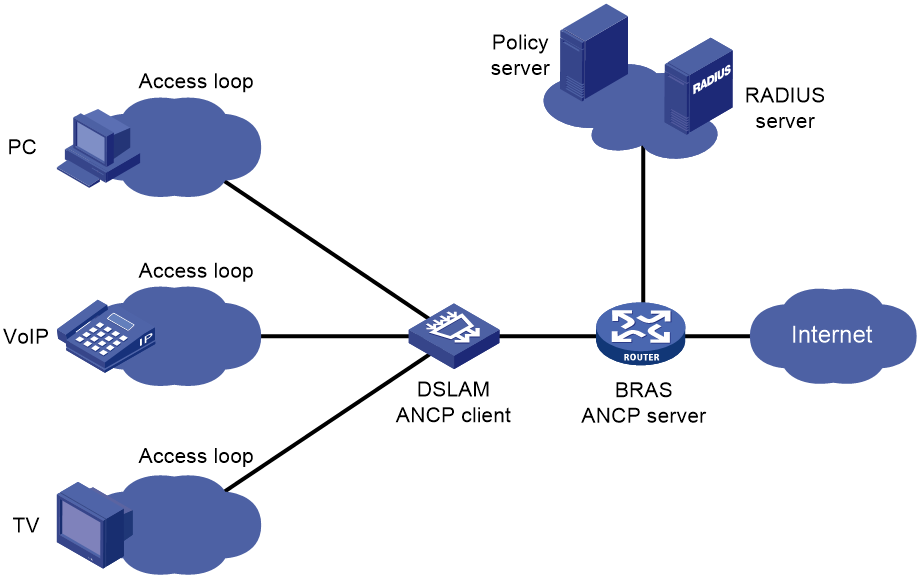
ANCP works between the DSLAM and the BRAS as follows:
1. The ANCP client establishes a TCP connection to the ANCP server on port 6068.
2. The client and server establish an ANCP adjacency and complete ANCP negotiation:
a. The client and the server send each other a SYN message.
The SYN message contains the version number, adjacency timer, sender MAC address, and the capabilities that the sender supports.
The BRAS can only use its bridge MAC as the sender MAC address. By default, the DSLAM uses its bridge MAC as the sender MAC address. Its sender MAC address is configurable.
ANCP retransmits the SYN message if it does not receive the SYN message from its peer before the proposed adjacency timer expires. If SYN retransmission attempts exceed the limit, ANCP terminates the TCP connection.
b. The client and the server send each other a SYNACK message that contains negotiated values.
The negotiated values include the longer adjacency timer and the capabilities supported by both ends.
The capabilities supported by the ANCP server include dynamic topology discovery, DSL service profile assignment, and DSL OAM.
The two ends cannot establish an adjacency if they use different version numbers.
ANCP retransmits the SYNACK message if it does not receive the SYNACK message from its peer before the negotiated adjacency timer expires. If SYNACK retransmission attempts exceed the limit, ANCP terminates the TCP connection.
c. The server and the client send each other an ACK message to establish an ANCP adjacency.
ANCP retransmits the ACK message if it does not receive the ACK message from its peer before the negotiated adjacency timer expires. If one end does not receive an ACK message from its peer within three intervals, it sends a RSTACK message to terminate the TCP connection.
3. ANCP performs the following functions:
¡ ANCP adjacency maintenance
The client and the server periodically send ACK messages at the interval set by the negotiated adjacency timer. If one end does not receive an ACK message from its peer within three intervals, it sends a RSTACK message to terminate the TCP connection.
¡ Dynamic topology discovery
The client sends information about active DSLs to the BRAS. The information includes DSL status, and the actual and maximum uplink and downlink rates. When an active DSL has a state or parameter change, the client notifies the server about the change.
The server uses the DSL information to avoid congestion on the access network.
¡ Service profile assignment
The RADIUS server assigns a service profile to the ANCP server when a user accesses the network or customizes services through a DSL. The ANCP server sends the service profile to the ANCP client. The ANCP client applies the service profile to the DSL.
The ANCP server uses a DSL ID in the DHCP Option 82 or PPPoE+ message from the ANCP client to identify a DSL.
¡ DSL OAM
The ANCP server sends a message to the ANCP client for DSL OAM. The ANCP client performs loopback detection on the specified DSL and sends the result to the ANCP server.
Protocols and standards
· RFC 3292: GSMPv3
· RFC 6320: Protocol for Access Node Control Mechanism in Broadband Networks
ANCP tasks at a glance
To configure ANCP, perform the following tasks:
2. (Optional.) Configuring the adjacency timer
3. (Optional.) Configuring the maximum number of retransmission attempts
5. Configuring an ANCP neighbor ID
6. Configuring a source interface for a neighbor
7. (Optional.) Configuring the DSL entry aging time
8. (Optional.) Configuring ANCP OAM
9. (Optional.) Assigning a service profile to a DSL
Enabling the ANCP server
About this task
You must enable the ANCP server. If the ANCP server is disabled, the system terminates all ANCP adjacencies and closes TCP port 6068.
Procedure
1. Enter system view.
system-view
2. Enable the ANCP server.
ancp enable
By default, the ANCP server is disabled.
Configuring the adjacency timer
About this task
The ANCP server and the ANCP client exchange SYN packets to negotiate adjacency timers. The two ends use the longer adjacency timer to send SYNACK and ACK packets.
Restrictions and guidelines
If you modify the adjacency timer after an ANCP adjacency is established, the change does not take effect immediately. The change takes effect after the ANCP adjacency is disconnected and adjacency timers are negotiated again.
Procedure
1. Enter system view.
system-view
2. Configure the adjacency timer.
ancp session interval interval
The default adjacency timer is 25 seconds.
Configuring the maximum number of retransmission attempts
About this task
The ANCP server retransmits a SYN or SYNACK message if it does not receive the message from its peer before the adjacency timer expires. If the peer does not respond after the retransmission attempts reach the maximum, the server closes the TCP connection.
Procedure
1. Enter system view.
system-view
2. Configure the maximum number of retransmission attempts.
ancp session retransmit retransmit-value
By default, the maximum number of retransmission attempts is 10.
Creating an ANCP neighbor
About this task
ANCP clients are the ANCP neighbors of the ANCP server. You can create multiple ANCP neighbors and configure parameters for each neighbor.
Procedure
1. Enter system view.
system-view
2. Create an ANCP neighbor and enter its view.
ancp neighbor neighbor-name
By default, no ANCP neighbor exists.
Configuring an ANCP neighbor ID
About this task
The ANCP server uses ANCP neighbor IDs to identify ANCP clients. If the MAC address of a client does not match any ANCP neighbor ID, the server closes the TCP connection to the client.
Restrictions and guidelines
A neighbor ID uniquely identifies an ANCP neighbor.
If you remove a neighbor ID, the server closes the TCP connection to the corresponding neighbor.
Procedure
1. Enter system view.
system-view
2. Enter ANCP neighbor view.
ancp neighbor neighbor-name
3. Configure an ANCP neighbor ID.
peer-id peer-id
By default, no ANCP neighbor ID exists.
Configuring a source interface for a neighbor
About the sources interface for a neighbor
A neighbor-specific source interface must be a loopback interface. The ANCP server uses one of the following addresses as the source IP address for TCP packets sent to an ANCP neighbor:
· The primary IPv4 address of the source interface.
· The first IPv6 global unicast address of the source interface.
Restrictions and guidelines for the source interface of a neighbor
You must configure a global source interface or neighbor-specific source interface, or both. The ANCP server prefers the neighbor-specific source interface over the global source interface when it communicates with the neighbor.
If you delete a neighbor-specific source interface, and no global source interface exists, the device closes TCP port 6068 for the neighbor. If you change the source interface, the device uses the IP address of the new source interface. The delete or change operation does not affect existing TCP connections.
Configuring the global source interface in system view
1. Enter system view.
system-view
2. Configure the global source interface.
ancp source-interface loopback interface-number
By default, no global source interface exists.
Configuring a source interface for a neighbor in neighbor view
1. Enter system view.
system-view
2. Enter ANCP neighbor view.
ancp neighbor neighbor-name
3. Configure a source interface for a neighbor.
source-interface loopback interface-number
By default, no source interface is configured for a neighbor.
Configuring the DSL entry aging time
About this task
The server records DSL information in DSL entries. If a user on a DSL goes offline, the server will remove the corresponding DSL entry when its aging timer expires.
Restrictions and guidelines
If an ANCP neighbor needs to reboot the DSL after receiving a service profile, the DSL entry aging time configured for the neighbor must be long enough for the neighbor to complete the reboot.
Procedure
1. Enter system view.
system-view
2. Enter ANCP neighbor view.
ancp neighbor neighbor-name
3. Configure the DSL entry aging time.
aging-time value
The default aging time is 150 seconds.
Configuring ANCP OAM
About this task
You can start an OAM test for a DSL to monitor the status of the DSL. The BRAS sends a message to the DSLAM for DSL OAM. The DSLAM performs status detection on the specified DSL and sends the result to the BRAS.
Procedure
1. Enter system view.
system-view
2. Start an ANCP OAM test for a DSL.
ancp oam [ count test-counter | timeout time-value ] * access-loop circuit-id
Assigning a service profile to a DSL
About this task
The ANCP server can convey service profiles received from the RADIUS server to clients. You can also manually assign a service profile to a DSL from the server.
Restrictions and guidelines
The service profile must already exist on the DSLAM.
Procedure
1. Enter system view.
system-view
2. Assign a service profile to a DSL.
ancp access-loop-configure circuit-id circuit-id service-profile profile-name [ timeout time-value ]
Display and maintenance commands for ANCP
Execute display commands in any view and reset command in user view.
|
Task |
Command |
|
Display information about ANCP neighbors. |
display ancp neighbor [ neighbor-name ] |
|
Display information about DSL entries. |
display ancp access-loop [ circuit-id circuit-id | neighbor neighbor-name ] |
|
Display ANCP neighbor statistics. |
display ancp statistics [ neighbor neighbor-name ] |
|
Clear ANCP neighbor information and close TCP connections. |
reset ancp neighbor [ neighbor-name ] |
|
Delete DSL entries. |
reset ancp access-loop [ circuit-id circuit-id | neighbor neighbor-name ] |
|
Clear ANCP neighbor statistics. |
reset ancp statistics [ neighbor neighbor-name ] |
ANCP configuration examples
Example: Configuring ANCP
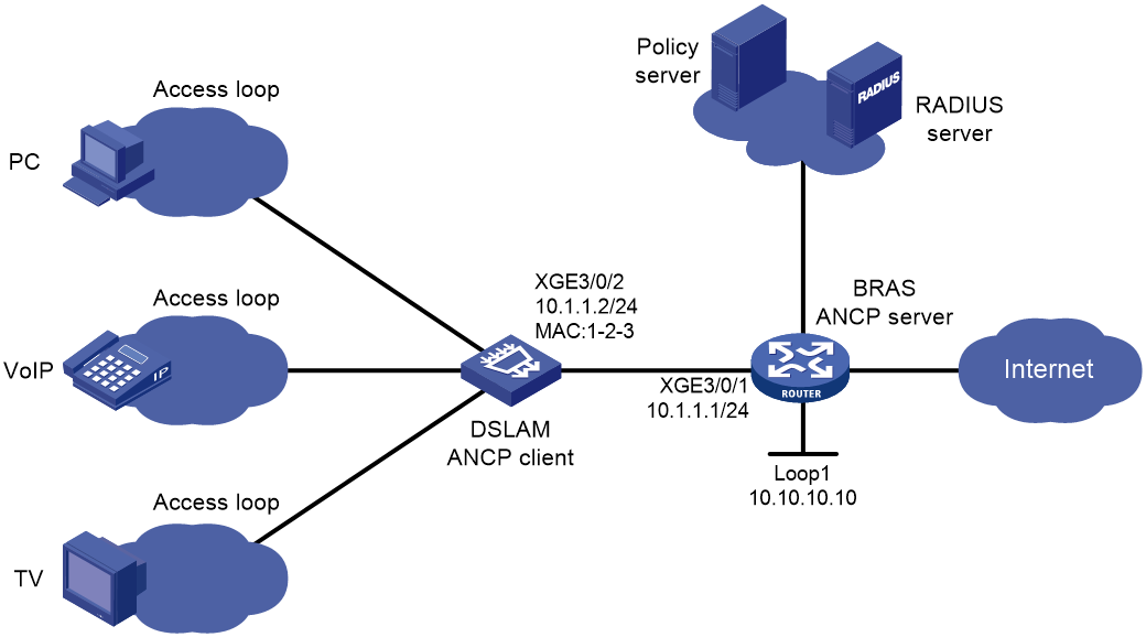
Network configuration
As shown in Figure 2, users access the network through IPoE or PPPoE. The RADIUS server performs user authentication and accounting.
Configure ANCP to achieve the following purposes:
· The BRAS can dynamically discover DSLs on the DSLAM.
· The BRAS can configure DSLs.
· The BRAS can perform OAM tests on DSLs.
Prerequisites
1. Configure the DSLAM so it can reach interface loopback 1 on the BRAS.
2. Enable the ANCP client on the DSLAM.
3. Configure BRAS access, including the authentication scheme, accounting scheme, RADIUS server, address pool, uplink interfaces, and so on. For more information, see related configuration guides.
Procedure
# Enable the ANCP server on the BRAS.
<BRAS> system-view
[BRAS] ancp enable
# Create an ANCP neighbor.
[BRAS] ancp neighbor test1
# Configure an ANCP neighbor ID.
[BRAS-ancp-neighbor-test1] peer-id 1-2-3
[BRAS-ancp-neighbor-test1] quit
# Configure the source interface for the ANCP neighbor.
[BRAS] interface loopback 1
[BRAS-LoopBack1] ip address 10.10.10.10
[BRAS-LoopBack1] quit
[BRAS] ancp neighbor test1
[BRAS-ancp-neighbor-test1] source-interface loopback 1
# Configure the DSL entry aging time as 100 seconds.
[BRAS-ancp-neighbor-test1] aging-time 100
[BRAS-ancp-neighbor-test1] quit
Verifying the configuration
# Verify that the BRAS and the DSLAM have established an ANCP adjacency.
[BRAS] display ancp neighbor test1
Neighbor name : test1
Peer ID : 0001-0002-0003
Source interface : LoopBack1
Session message interval : 25 s
Session message retransmit : 10
Aging time : 100 s
State : used
Peer IP : 10.1.1.2
Peer port : 510
Neighbor capacities : discovery, line-cfg, oam
Negotiated interval : 25.0 s
Access loop number : 3
# Verify that the BRAS has created DSL entries.
[BRAS] display ancp access-loop
Total entries: 3
Neighbor name Peer ID Circuit ID State
test1 0001-0002-0003 Access1 UP
test1 0001-0002-0003 Access2 UP
test1 0001-0002-0003 Access3 UP
[BRAS] display ancp access-loop circuit-id Access1
Neighbor name : test1
Circuit ID : Access1
Remote ID : remote3
Peer ID : 0001-0002-0003
DSL type : ADSL1
Actual data rate upstream : 512 Kbps
Actual data rate downstream : 1536 Kbps
Min data rate upstream : 32 Kbps
Min data rate downstream : 32 Kbps
Attainable data rate upstream : 96 Kbps
Attainable data rate downstream : 96 Kbps
Max data rate upstream : 64 Kbps
Max data rate downstream : 24544 Kbps
Min low power data rate upstream : 0 Kbps
Min low power data rate downstream : 0 Kbps
Max delay upstream : 6 s
Max delay downstream : 16 s
Actual delay upstream : 4 s
Actual delay downstream : 16 s
Data link : ETHERNET
Encapsulation 1 : Untagged Ethernet
Encapsulation 2 : NA
# Verify that the BRAS can successfully assign a service profile.
[BRAS] ancp access-loop-configure circuit-id Access1 service-profile profile1 timeout 10
Issuing service profile name profile1 for Access1. Please wait…
Issued the service profile name successfully.
# Verify that the BRAS can successfully start an OAM test on a DSL.
[BRAS] ancp oam count 5 timeout 5 access-loop Access1
OAM testing Access1. Please wait…
OAM test succeeded.