- Table of Contents
-
- 15-BRAS Services Configuration Guide
- 00-Preface
- 01-AAA configuration
- 02-ANCP configuration
- 03-PPP configuration
- 04-Value-added services configuration
- 05-DHCP configuration
- 06-DHCPv6 configuration
- 07-User profile configuration
- 08-Connection limit configuration
- 09-L2TP configuration
- 10-PPPoE configuration
- 11-IPoE configuration
- 12-UCM configuration
- Related Documents
-
| Title | Size | Download |
|---|---|---|
| 05-DHCP configuration | 1.31 MB |
Vendor-specific option (Option 43)
Relay agent option (Option 82)
DHCP address allocation mechanisms
Principles for selecting an IP pool
IP address allocation sequence
Configuring an IP pool on the DHCP server
Configuring an IP pool on a common network
Configuring an IP pool on a BAS network
Specifying gateways for DHCP clients
Specifying a domain name suffix for DHCP clients
Specifying DNS servers for DHCP clients
Specifying WINS servers and NetBIOS node type for DHCP clients
Specifying BIMS server for DHCP clients
Specifying the configuration file for DHCP client automatic configuration
Specifying a server for DHCP clients
Configuring Option 184 parameters for DHCP clients
Applying an IP pool to a VPN instance
Configuring the DHCP user class allowlist
Configuring IP address reservation
Enabling random IP address allocation for common network
Binding gateways to DHCP server's MAC address
Advertising network segments that are assigned to clients
Enabling host route advertisement
Enabling route logging for IP address pools
Applying an IP pool to an interface
Configuring a DHCP policy for dynamic assignment
Enabling DHCP policy-first IP pool selection for IPoE users
Allocating different IP addresses to DHCP clients with the same MAC
Enabling the DHCP server on an interface
Configuring IP address conflict detection
Enabling handling of Option 82
Configuring the DHCP server security features
Restrictions and guidelines for DHCP server security feature configuration
Configuring DHCP flood attack protection
Configuring DHCP starvation attack protection
Configuring interface-based DHCP attack suppression
Configuring DHCP server compatibility
Configuring the DHCP server to always broadcast responses
Disabling Option 60 encapsulation in DHCP replies
Enabling the DHCP server to return a DHCP-NAK message upon client notions of incorrect IP addresses
Configuring the DHCP server to ignore BOOTP requests
Configuring the DHCP server to send BOOTP responses in RFC 1048 format
Setting the DSCP value for DHCP packets sent by the DHCP server
Configuring DHCP packet rate limit on a DHCP server interface
Configuring DHCP binding auto backup
Enabling client offline detection on the DHCP server
Enabling the IP conflicting user offline feature
Specifying a DHCP request processing method for roaming DHCP clients
Configuring SNMP notifications for the DHCP server
About SNMP DHCP server notifications
Enabling IP exhaustion notifications
Enabling IP allocation alarm notifications
Enabling IP allocation failure alarming
Enabling IP usage alarm notifications
Enabling IP resource exhaustion alarming for IP pool groups
Enabling IP address resource usage alarming for IP pool groups
Enabling DHCP logging on the DHCP server
Enabling IP resource exhaustion logging
Display and maintenance commands for DHCP server
DHCP server configuration examples
Example: Configuring static IP address assignment
Example: Configuring dynamic IP address assignment
Example: Configuring DHCP user class
Example: Configuring DHCP user class allowlist
Example: Configuring primary and secondary network segments
Example: Customizing DHCP option
Troubleshooting DHCP server configuration
Failure to obtain a non-conflicting IP address
Configuring the DHCP relay agent
DHCP relay agent support for Option 82
DHCP relay agent support for MCE
Restrictions and guidelines: DHCP relay agent configuration
DHCP relay agent tasks at a glance
Enabling the DHCP relay agent on an interface
Specifying DHCP servers on a relay agent
Configuring a remote BAS IP pool on a DHCP relay agent
Specifying the DHCP server selection algorithm
Configuring DHCP server liveness detection
Configuring the DHCP relay agent security features
Enabling the DHCP relay agent to record relay entries
Enabling periodic refresh of dynamic relay entries
Enabling lease release notification
Configuring DHCP flood attack protection
Enabling DHCP starvation attack protection
Enabling DHCP proxy on the DHCP relay agent
Enabling client offline detection on the DHCP relay agent
Configuring interface-based DHCP attack suppression
Configuring the DHCP relay agent to release an IP address
Configuring DHCP relay agent support for Option 82
Setting the DSCP value for DHCP packets sent by the DHCP relay agent
Configuring DHCP packet rate limit on a DHCP relay interface
Specifying the DHCP relay agent address for the giaddr field
Manually specifying the DHCP relay agent address for the giaddr field
Configuring smart relay to specify the DHCP relay agent address for the giaddr field
Specifying the source IP address for relayed DHCP requests
About specifying the source IP address for relayed DHCP requests
Specifying the source IP address for relayed DHCP requests (interface view)
Specifying the source IP address for relayed DHCP requests (remote BAS IP pool view)
Configuring the DHCP relay agent to always unicast relayed DHCP responses
Configuring forwarding DHCP replies based on Option 82
Setting the maximum number of DHCP-NAK packets
Enabling the IP conflicting user offline feature
Specifying a DHCP request processing method for roaming DHCP clients
Enabling the non-first-hop DHCP relay agent feature
Enabling DHCP-NAK-triggered remote BAS IP pool switchover
Display and maintenance commands for DHCP relay agent
DHCP relay agent configuration examples
Example: Configuring basic DHCP relay agent
Example: Configuring Option 82
Example: Configuring DHCP server selection
Troubleshooting DHCP relay agent configuration
Failure of DHCP clients to obtain configuration parameters through the DHCP relay agent
Restrictions and guidelines: DHCP client configuration
Enabling DHCP client on an interface
Configuring a DHCP client ID for an interface
Enabling duplicated address detection
Setting the DSCP value for DHCP packets sent by the DHCP client
Display and maintenance commands for DHCP client
DHCP client configuration examples
Example: Configuring DHCP client
Application of trusted and untrusted ports
DHCP snooping support for Option 82
Restrictions and guidelines: DHCP snooping configuration
DHCP snooping tasks at a glance
Configuring basic DHCP snooping
Configuring DHCP snooping support for Option 82
Configuring DHCP snooping entry auto backup
Setting the maximum number of DHCP snooping entries
Configuring DHCP snooping security features
Enabling DHCP starvation attack protection
Enabling DHCPREQUEST attack protection
Configuring a DHCP packet blocking port
Enabling DHCP snooping logging
Display and maintenance commands for DHCP snooping
DHCP snooping configuration examples
Example: Configuring basic DHCP snooping
Example: Configuring DHCP snooping support for Option 82
Obtaining an IP address dynamically
Configuring an interface to use BOOTP for IP address acquisition
Display and maintenance commands for BOOTP client
BOOTP client configuration examples
Example: Configuring BOOTP client
DHCP overview
DHCP network model
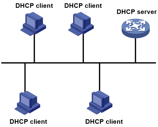
The Dynamic Host Configuration Protocol (DHCP) provides a framework to assign configuration information to network devices.
Figure 1 shows a typical DHCP application scenario in which the DHCP clients and the DHCP server reside on the same subnet. The DHCP clients on one subnet can also obtain configuration parameters from a DHCP server on another subnet through a DHCP relay agent. For more information about the DHCP relay agent, see "Configuring the DHCP relay agent."
Figure 1 A typical DHCP application
DHCP address allocation
Allocation mechanisms
DHCP supports the following allocation mechanisms:
· Static allocation—The network administrator assigns an IP address to a client, such as a WWW server, and DHCP conveys the assigned address to the client.
· Automatic allocation—DHCP assigns a permanent IP address to a client.
· Dynamic allocation—DHCP assigns an IP address to a client for a limited period of time, which is called a lease. Most DHCP clients obtain their addresses in this way.
IP address allocation process
Figure 2 IP address allocation process
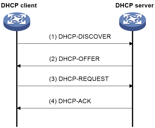
As shown in Figure 2, a DHCP server assigns an IP address to a DHCP client in the following process:
1. The client broadcasts a DHCPDISCOVER message to locate a DHCP server.
2. Each DHCP server offers configuration parameters such as an IP address to the client in a DHCP-OFFER message. The sending mode of the DHCP-OFFER is determined by the flag field in the DHCPDISCOVER message. For more information, see "DHCP message format."
3. If the client receives multiple offers, it accepts the first received offer, and broadcasts it in a DHCPREQUEST message to formally request the IP address. (IP addresses offered by other DHCP servers can be assigned to other clients.)
4. All DHCP servers receive the DHCPREQUEST message. However, only the server selected by the client does one of the following operations:
¡ Returns a DHCP-ACK message to confirm that the client can use the requested IP address.
¡ Returns a DHCP-NAK message to deny the IP address allocation.
After receiving the DHCP-ACK message, the client verifies the following details before using the assigned IP address:
· The assigned IP address is not in use. To verify this, the client broadcasts a gratuitous ARP packet. The assigned IP address is not in use if no response is received within the specified time.
· The assigned IP address is not on the same subnet as any IP address in use on the client.
If the IP address does not pass verification, the client sends a DHCP-DECLINE message to the server, and then requests a new IP address.
IP address lease extension
A dynamically assigned IP address has a lease. When the lease expires, the IP address is reclaimed by the DHCP server. To continue using the IP address, the client must extend the lease duration.
When about half of the lease duration elapses, the DHCP client unicasts a DHCPREQUEST to the DHCP server to extend the lease. Depending on the availability of the IP address, the DHCP server returns a DHCP-ACK or DHCP-NAK unicast message.
· A DHCP-ACK message confirms that the client's lease duration has been extended.
· A DHCP-NAK message denies the request.
The client broadcasts another DHCPREQUEST message for lease extension if it has not received a DHCP-ACK or DHCP-NAK reply when about seven-eighths of the lease duration elapses. Again, depending on the availability of the IP address, the DHCP server returns either a DHCP-ACK or a DHCP-NAK message.
DHCP message format
All types of DHCP message use the same message, except that they have different values for some of the fields.
Figure 3 shows the DHCP message format. The numbers in parentheses indicate the size of each field in bytes.
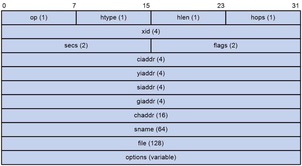
· op—General type of the message. A value of 1 indicates a request message and a value of 2 indicates a reply message.
· htype, hlen—Hardware address type and length of the DHCP client.
· hops—Number of relay agents that a request message traveled.
· xid—Transaction ID, a random number chosen by the client to identify an IP address allocation transaction.
· secs—The number of seconds elapsed since the client began address acquisition or renewal process. This field is reserved and fixed at 0.
· flags—The leftmost bit is defined as the BROADCAST (B) flag. If this flag is set to 0, the DHCP server sent a reply back by unicast. If this flag is set to 1, the DHCP server sent a reply back by broadcast. The remaining bits of the flags field are reserved for future use.
· ciaddr—Client IP address if the client has an IP address that is valid and usable. Otherwise, set to zero. (The client does not use this field to request an IP address to lease.)
· yiaddr—Your IP address. It is an IP address assigned by the DHCP server to the DHCP client.
· siaddr—Server IP address, from which the client obtained configuration parameters.
· giaddr—Gateway IP address. It is the IP address of the first relay agent to which a request message travels.
· chaddr—Client hardware address.
· sname—Server host name, from which the client obtained configuration parameters.
· file—Boot file (also called system software image) name and path information, defined by the server to the client.
· options—Optional parameters field that is variable in length. Optional parameters include the message type, lease duration, domain name server IP address, and WINS IP address.
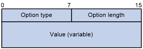
DHCP options
DHCP extends the message format as an extension to BOOTP for compatibility. DHCP uses the options field to carry information for dynamic address allocation and provide additional configuration information for clients.
Figure 4 DHCP option format
Common DHCP options
The following are common DHCP options:
· Option 3—Router option. It specifies the gateway address to be assigned to the clients.
· Option 6—DNS server option. It specifies the DNS server IP address to be assigned to the clients.
· Option 33—Static route option. It specifies a list of classful static routes (the destination addresses in these static routes are classful) that a client should add into its routing table. If both Option 33 and Option 121 exist, Option 33 is ignored.
· Option 51—IP address lease option.
· Option 53—DHCP message type option. It identifies the type of the DHCP message.
· Option 55—Parameter request list option. It is used by a DHCP client to request specified configuration parameters. The option includes values that correspond to the parameters requested by the client.
· Option 60—Vendor class identifier option. A DHCP client uses this option to identify its vendor. A DHCP server uses this option to distinguish DHCP clients, and assigns IP addresses to them.
· Option 66—TFTP server name option. It specifies the TFTP server domain name to be assigned to the clients.
· Option 67—Boot file name option. It specifies the boot file name to be assigned to the client.
· Option 121—Classless route option. It specifies a list of classless static routes (the destination addresses in these static routes are classless) that a client should add into its routing table. If both Option 33 and Option 121 exist, Option 33 is ignored.
· Option 150—TFTP server IP address option. It specifies the TFTP server IP address to be assigned to the clients.
For more information about DHCP options, see RFC 2132 and RFC 3442.
Custom DHCP options
Some options, such as Option 43, Option 82, and Option 184, have no standard definitions in RFC 2132.
Vendor-specific option (Option 43)
Option 43 function
DHCP servers and clients use Option 43 to exchange vendor-specific configuration information.
The DHCP client can obtain the following information through Option 43:
· ACS parameters, including the ACS URL, username, and password.
· Service provider identifier, which is acquired by the CPE from the DHCP server and sent to the ACS for selecting vender-specific configurations and parameters. For more information about CPE and ACS, see CWMP configuration in Network Management and Monitoring Configuration Guide.
· PXE server address, which is used to obtain the boot file or other control information from the PXE server.
· AC address, which is used by an AP to obtain the boot file or other control information from the AC.
Option 43 format
Figure 5 Option 43 format
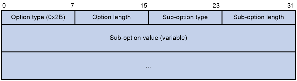
Network configuration parameters are carried in different sub-options of Option 43 as shown in Figure 5.
· Sub-option type—The field value can be 0x01 (ACS parameter sub-option), 0x02 (service provider identifier sub-option), or 0x80 (PXE server address sub-option).
· Sub-option length—Excludes the sub-option type and sub-option length fields.
· Sub-option value—The value format varies by sub-option.
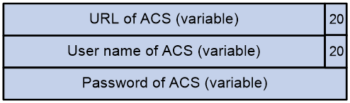
Sub-option value field format
· ACS parameter sub-option value field—Includes the ACS URL, username, and password separated by spaces (hexadecimal number 20) as shown in Figure 6.
Figure 6 ACS parameter sub-option value field
· Service provider identifier sub-option value field—Includes the service provider identifier.
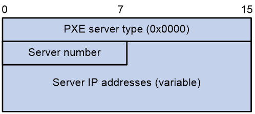
· PXE server address sub-option value field—Includes the PXE server type that can only be 0, the server number that indicates the number of PXE servers contained in the sub-option, and server IP addresses, as shown in Figure 7.
Figure 7 PXE server address sub-option value field
Relay agent option (Option 82)
Option 82 is the relay agent option. It records the location information about the DHCP client. When a DHCP relay agent or DHCP snooping device receives a client's request, it adds Option 82 to the request and sends it to the server.
The administrator can use Option 82 to locate the DHCP client and further implement security control and accounting. The DHCP server can use Option 82 to provide individual configuration policies for the clients.
Option 82 can include a maximum of 255 sub-options and must include a minimum of one sub-option. Option 82 supports two sub-options: sub-option 1 (Circuit ID) and sub-option 2 (Remote ID). Option 82 has no standard definition. Its padding formats vary by vendor.
· Circuit ID has the following padding modes:
¡ String padding mode—Includes a character string specified by the user.
¡ Normal padding mode—Includes the VLAN ID and interface number of the interface that receives the client's request.
¡ Verbose padding mode—Includes the access node identifier specified by the user, and the VLAN ID, interface number and interface type of the interface that receives the client's request.
· Remote ID has the following padding modes:
¡ String padding mode—Includes a character string specified by the user.
¡ Normal padding mode—Includes the MAC address of the DHCP relay agent interface or the MAC address of the DHCP snooping device that receives the client's request.
¡ Sysname padding mode—Includes the name of the device. To set the device name, use the sysname command in system view.
Option 184
Option 184 is a reserved option. You can define the parameters in the option as needed. The device supports Option 184 carrying voice related parameters, so a DHCP client with voice functions can get voice parameters from the DHCP server.
Option 184 has the following sub-options:
· Sub-option 1—Specifies the IP address of the primary network calling processor. The primary processor acts as the network calling control source and provides program download services. For Option 184, you must define sub-option 1 to make other sub-options take effect.
· Sub-option 2—Specifies the IP address of the backup network calling processor. DHCP clients contact the backup processor when the primary one is unreachable.
· Sub-option 3—Specifies the voice VLAN ID and the result whether the DHCP client takes this VLAN as the voice VLAN.
· Sub-option 4—Specifies the failover route that includes the IP address and the number of the target user. A SIP VoIP user uses this IP address and number to directly establish a connection to the target SIP user when both the primary and backup calling processors are unreachable.
Protocols and standards
· RFC 2131, Dynamic Host Configuration Protocol
· RFC 2132, DHCP Options and BOOTP Vendor Extensions
· RFC 1542, Clarifications and Extensions for the Bootstrap Protocol
· RFC 3046, DHCP Relay Agent Information Option
· RFC 3442, The Classless Static Route Option for Dynamic Host Configuration Protocol (DHCP) version 4
Configuring the DHCP server
About DHCP server
A DHCP server manages a pool of IP addresses and client configuration parameters. It selects an IP address and configuration parameters from the IP pool and allocates them to a requesting DHCP client.
DHCP address allocation mechanisms
Configure the following address allocation mechanisms as needed:
· Dynamic address allocation
¡ A primary network segment being divided into multiple address ranges
¡ A primary network segment and multiple secondary network segments
Static address allocation
Use this method to allocate IP addresses to DHCP clients that require static IP addresses. One typical example is a Web server.
The DHCP server supports the following types of bindings:
· IP-to-MAC bindings— After you create an IP-to-MAC binding for a client, the DHCP server assigns the IP address in the binding to the client.
· IP-to-client ID bindings—Some DHCP clients support encapsulating their client IDs in the DHCPDISCOVER messages. For these clients, you can configure IP-client ID bindings. The DHCP server assigns the IP address in the binding to the requesting client. For more information about the client ID, see "Configuring a DHCP client ID for an interface."
A primary network segment being divided into multiple address ranges
An address range includes a common IP address range and IP address ranges for DHCP user classes.
Upon receiving a DHCP request, the DHCP server finds a user class matching the client and selects an IP address in the address range of the user class for the client. A user class can include multiple matching rules, and a client matches the user class as long as it matches any of the rules. In IP pool view, you can specify different address ranges for different user classes.
The DHCP server selects an IP address for a client by performing the following steps:
1. DHCP server compares the client against DHCP user classes in the order they are configured.
2. If the client matches a user class, the DHCP server selects an IP address from the address range of the user class.
3. If the matching user class has no assignable addresses, the DHCP server compares the client against the next user class. If all the matching user classes have no assignable addresses, the DHCP server selects an IP address from the common address range.
4. If the DHCP client does not match any DHCP user class, the DHCP server selects an address in the IP address range specified by the address range command. If the address range has no assignable IP addresses or it is not configured, the address allocation fails.
|
|
NOTE: All address ranges must belong to the primary network segment. If an address range does not reside on the primary network segment, DHCP cannot assign the addresses in the address range. |
A primary network segment and multiple secondary network segments
The DHCP server selects an IP address from the primary network segment first. If there is no assignable IP address on the primary network segment, the DHCP server selects an IP address from secondary network segments in the order they are configured.
Principles for selecting an IP pool
The DHCP server observes the following principles to select an IP pool for a client:
1. If there is an IP pool where an IP address is statically bound to the MAC address or ID of the client, the DHCP server selects this IP pool and assigns the statically bound IP address and other configuration parameters to the client.
2. If the receiving interface has a DHCP policy and the DHCP client matches a user class, the DHCP server selects the IP pool that is bound to the matching user class. If no matching user class is found, the server assigns an IP address and other parameters from the default IP pool. If no default IP pool is specified or the default IP pool does not have assignable IP addresses, the address assignment fails.
3. If the receiving interface has an IP pool applied, the DHCP server selects an IP address and other configuration parameters from this IP pool.
4. If the above conditions are not met, the DHCP server selects an IP pool depending on the client location.
¡ Client on the same network segment as the server—The DHCP server compares the IP address of the receiving interface with the primary network segments of all IP pools.
- If a match is found, the server selects the IP pool with the longest-matching primary network segment.
- If no match is found, the DHCP server compares the IP address with the secondary network segments of all IP pools. The server selects the IP pool with the longest-matching secondary network segment.
¡ Client on a different network segment than the server—The DHCP server compares the IP address in the giaddr field of the DHCP request with the primary network segments of all IP pools.
- If a match is found, the server selects the IP pool with the longest-matching primary network segment.
- If no match is found, the DHCP server compares the IP address with the secondary network segments of all IP pools. The server selects the IP pool with the longest-matching secondary network segment.
For example, two IP pools 1.1.1.0/24 and 1.1.1.0/25 are configured but not applied to any DHCP server's interfaces.
· If the IP address of the receiving interface is 1.1.1.1/25, the DHCP server selects the IP pool 1.1.1.0/25. If the IP pool has no available IP addresses, the DHCP server will not select the other pool and the address allocation will fail.
· If the IP address of the receiving interface is 1.1.1.130/25, the DHCP server selects the IP pool 1.1.1.0/24.
To ensure correct address allocation, keep the IP addresses used for dynamic allocation on one of the network segments:
· Clients on the same network segment as the server—Network segment where the DHCP server receiving interface resides.
· Clients on a different network segment than the server—Network segment where the first DHCP relay interface that faces the clients resides.
|
|
NOTE: As a best practice, configure a minimum of one matching primary network segment in your network. Otherwise, the DHCP server selects only the first matching secondary network segment for address allocation. If the network has more DHCP clients than the assignable IP addresses in the secondary network segment, not all DHCP clients can obtain IP addresses. |
IP address allocation sequence
The DHCP server selects an IP address for a client in the following sequence:
1. IP address statically bound to the client's MAC address or ID.
2. IP address that was ever assigned to the client.
3. IP address designated by the Option 50 field in the DHCPDISCOVER message sent by the client.
Option 50 is the Requested IP Address option. The client uses this option to specify the wanted IP address in a DHCPDISCOVER message. The content of Option 50 is user defined.
4. First assignable IP address found in the way discussed in "DHCP address allocation mechanisms" and "Principles for selecting an IP pool."
5. IP address that was a conflict or passed its lease duration. If no IP address is assignable, the server does not respond.
DHCP server tasks at a glance
To configure the DHCP server, perform the following tasks:
1. (Optional.) Creating a DHCP user class
2. Configuring an IP pool on the DHCP server
3. Configuring an IP pool group
4. (Optional.) Modifying the IP pool selection method on the DHCP server
¡ Applying an IP pool to an interface
¡ Configuring a DHCP policy for dynamic assignment
¡ Enabling DHCP policy-first IP pool selection for IPoE users
5. (Optional.) Allocating different IP addresses to DHCP clients with the same MAC
7. Enabling the DHCP server on an interface
8. (Optional.) Configuring advanced DHCP features
¡ Configuring IP address conflict detection
¡ Enabling handling of Option 82
¡ Configuring the DHCP server security features
¡ Configuring DHCP server compatibility
¡ Setting the DSCP value for DHCP packets sent by the DHCP server
¡ Configuring DHCP packet rate limit on a DHCP server interface
¡ Configuring DHCP binding auto backup
¡ Enabling client offline detection on the DHCP server
¡ Enabling the IP conflicting user offline feature
¡ Specifying a DHCP request processing method for roaming DHCP clients
9. (Optional.) Configuring SNMP notification and logging
¡ Configuring SNMP notifications for the DHCP server
¡ Enabling DHCP logging on the DHCP server
¡ Enabling IP resource exhaustion logging
Creating a DHCP user class
About this task
The DHCP server classifies DHCP users into different user classes according to the hardware address, option information, or the giaddr field in the received DHCP requests. The server allocates IP addresses and configuration parameters to DHCP clients in different user classes.
Procedure
1. Enter system view.
system-view
2. Create a DHCP user class and enter DHCP user class view.
dhcp class class-name
3. Configure a match rule for the DHCP user class.
if-match rule rule-number { hardware-address hardware-address mask hardware-address-mask | option option-code [ ascii ascii-string [ offset offset | partial ] | hex hex-string [ mask mask | offset offset length length | partial ] ] | relay-agent gateway-address }
By default, no match rule is configured for a DHCP user class.
Configuring an IP pool on the DHCP server
IP pool tasks at a glance
To configure an IP pool, perform the following tasks:
1. Creating an IP pool
¡ Configuring an IP pool on a common network
¡ Configuring an IP pool on a BAS network
2. Specifying configuration parameters for DHCP clients
¡ Specifying gateways for DHCP clients
¡ Specifying a domain name suffix for DHCP clients
¡ Specifying DNS servers for DHCP clients
¡ Specifying WINS servers and NetBIOS node type for DHCP clients
¡ Specifying BIMS server for DHCP clients
¡ Specifying the configuration file for DHCP client automatic configuration
¡ Specifying a server for DHCP clients
¡ Configuring Option 184 parameters for DHCP clients
3. (Optional.) Applying an IP pool to a VPN instance
4. (Optional.) Configuring the DHCP user class allowlist
5. (Optional.) Configuring IP address reservation
6. (Optional.) Enabling random IP address allocation for common network
7. (Optional.) Binding gateways to DHCP server's MAC address
8. (Optional.) Advertising network segments that are assigned to clients
9. (Optional.) Enabling host route advertisement
10. (Optional.) Enabling route logging for IP address pools
11. (Optional.) Locking an IP address pool
Configuring an IP pool on a common network
About this task
IP pools in a common network are called common IP pools.
You can use one of the following dynamic allocation methods to configure an IP pool in the common network:
· Specify a primary network segment and multiple address ranges.
· Specify a primary network segment and multiple secondary network segments.
In some scenarios, it is required to classify DHCP clients on the same network segment into different address blocks. To meet this requirement, you can configure DHCP user classes and specify different address ranges for them. The clients matching a user class can get the IP addresses of an address range. In addition, you can specify the default address range for the clients that do not match any user class. If this address range is not specified, such clients cannot obtain IP addresses.
If classifying clients is no needed, you do not need to configure DHCP user classes or their address ranges.
If an IP pool has a primary network segment and multiple secondary network segments, the server assigns IP addresses on a secondary network segment when the primary segment has no assignable IP addresses.
Restrictions and guidelines
When you configure a static binding, follow these restrictions and guidelines:
· The IP address of a static binding cannot be the IP address of the DHCP server interface. Otherwise, an IP address conflict occurs and the bound client cannot obtain an IP address.
· Multiple interfaces on the same device might all use DHCP to request a static IP address. In this case, use client IDs rather than the device's MAC address to identify the interfaces. Otherwise, IP address allocation will fail.
When you configure dynamic or automatic address allocation, follow these restrictions and guidelines:
· If you execute the network or address range command multiple times for the same IP pool, the most recent configuration takes effect.
· You can repeat the class command to specify different address ranges for different user classes.
· You can repeat the forbidden-ip command or the forbidden-ip-range command to exclude multiple address ranges from DHCP allocation.
· The forbidden-ip and forbidden-ip-range commands exclude IP addresses and IP ranges, respectively, from DHCP allocation in the IP pool for which they are executed. The forbidden IP addresses and IP ranges are still assignable in other IP pools. The dhcp server forbidden-ip command excludes IP addresses from DHCP allocation in any IP pools.
· When you execute the class range command to change the address range for a DHCP user class, use the following restrictions and guidelines:
¡ Make sure the new range contains the IP addresses that have been assigned so the online clients can renew their address lease successfully.
Upon receiving a lease renewal request for such an IP address, the DHCP server renews the lease for the requesting client while the existing lease continues to take effect until it is released upon expiration. To release a lease without waiting for its timeout, execute the reset dhcp server ip-in-use command.
¡ If the new range does not contain the IP address assigned to a client, the lease renewal attempt of the client will fail. The client must wait for the current lease to expire to request a new lease.
· An IP pool supports only one dynamic allocation method.
· For DHCP clients to obtain IP addresses on a PPPoE network with DHCP relay agents, set the lease duration to be longer than 2 minutes for dynamically assigned IP addresses.
· On a PPPoE network, static IP-to-MAC bindings are not supported.
Specifying a primary network segment and multiple address ranges in an IP pool
1. Enter system view.
system-view
2. Create an IP pool and enter its view.
ip pool pool-name
3. Configure a static binding.
static-bind ip-address ip-address [ mask-length | mask mask ] { client-identifier client-identifier | hardware-address hardware-address [ ethernet | token-ring ] }
By default, no static binding is configured.
You cannot specify an IP address in a static binding if you have excluded it from DHCP allocation by using the dhcp server forbidden-ip command.
4. Specify the primary network segment in the IP pool.
network network-address [ mask-length | mask mask ]
By default, no primary network segment is specified.
5. Specify the default address range.
address range start-ip-address end-ip-address
By default, no address range is specified.
6. Specify an IP address range for a DHCP user class.
class class-name range start-ip-address end-ip-address
By default, no IP address range is specified for a user class.
The DHCP user class must already be created by using the dhcp class command.
7. (Optional.) Set the address lease duration.
expired { allow-hint | { day day [ hour hour [ minute minute [ second second ] ] ] | unlimited } [ allow-hint ] }
The default setting is 1 day.
8. Exclude the specified IP addresses from dynamic allocation.
forbidden-ip ip-address&<1-8>
By default, except for the DHCP server IP address, all IP addresses in the IP pool are assignable.
9. (Optional.) Exclude an IP range from DHCP allocation in the address pool.
forbidden-ip-range start-ip-address [ end-ip-address ]
By default, except for the DHCP server IP address, all IP addresses in the IP pool are assignable.
10. (Optional.) Exclude IP addresses from automatic allocation in system view.
a. Return to system view.
quit
b. Exclude the specified IP addresses from DHCP allocation globally.
dhcp server forbidden-ip start-ip-address [ end-ip-address ] [ vpn-instance vpn-instance-name ]
By default, except for the IP address of the DHCP server interface, IP addresses in all IP pools are assignable.
You cannot exclude an IP address from DHCP allocation if it has been specified in a static DHCP binding by using the static-bind command.
Specifying a primary network segment and multiple secondary network segments in an IP pool
1. Enter system view.
system-view
2. Create an IP pool and enter its view.
ip pool pool-name
3. Configure a static binding.
static-bind ip-address ip-address [ mask-length | mask mask ] { client-identifier client-identifier | hardware-address hardware-address [ ethernet | token-ring ] }
By default, no static binding is configured.
4. Specify the primary network segment.
network network-address [ mask-length | mask mask ]
By default, no primary network segment is specified.
You can specify only one primary network segment in each IP pool. If you execute the network command multiple times, the most recent configuration takes effect.
5. (Optional.) Specify a secondary network segment.
network network-address [ mask-length | mask mask ] secondary
By default, no secondary network segment is specified.
You can specify a maximum of 96 secondary network segments in one common IP pool.
6. Set the address lease duration.
expired { allow-hint | { day day [ hour hour [ minute minute [ second second ] ] ] | unlimited } [ allow-hint ] }
The default setting is 1 day.
7. (Optional.) Exclude the specified IP addresses from DHCP allocation.
forbidden-ip ip-address&<1-8>
By default, except for the DHCP server IP address, all IP addresses in the IP pool are assignable.
To exclude multiple address ranges from the dynamic allocation, repeat this step.
8. (Optional.) Exclude an IP range from DHCP allocation in the address pool.
forbidden-ip-range start-ip-address [ end-ip-address ]
By default, except for the DHCP server IP address, all IP addresses in the IP pool are assignable.
9. (Optional.) Exclude IP addresses from DHCP allocation in system view.
a. Return to system view.
quit
b. Exclude the specified IP addresses from DHCP allocation globally.
dhcp server forbidden-ip start-ip-address [ end-ip-address ] [ vpn-instance vpn-instance-name ]
By default, except for the IP address of the DHCP server interface, IP addresses in all IP pools are assignable.
To exclude multiple address ranges globally, repeat this step.
Configuring an IP pool on a BAS network
About this task
IP pools in a BAS network are called BAS IP pools.
In a BAS network (for example, an IPoE network), the DHCP module contains the access module and the address management (AM) module. The access module cooperates with other modules for user authentication and the AM module assigns IP addresses. This structure ensures centralized management of IP addresses and efficient management of access users.
When a successfully authenticated and authorized user requests an IP address through DHCP, the AM module assigns an IP address and sends the address information to UCM. UCM permits the user to come online and performs accounting and other operations on the user.
If the BAS device acts as the DHCP server, configure a local BAS IP pool on the device. If the BAS device acts as a DHCP relay agent, configure a remote BAS IP pool on the device and specify the IP address of the DHCP server in this pool.
When the DHCP server assigns an IP address, it adds the network route for the IP address to the route management module. In a BAS network, you can classify user network routes (UNRs) based on their UNR tag values for route redistribution.
Restrictions and guidelines
You can set a network route tag value in system view or in IP pool view. The value set in IP pool view has higher priority than the one set in system view.
Procedure
1. Enter system view.
system-view
2. (Optional.) Set an IPv4 UNR tag.
ip unr { framed-ip-address-tag tag-value | framed-ip-netmask-tag tag-value | framed-route-tag tag-value | local-pool-tag tag-value | remote-pool-tag tag-value } *
By default, no IPv4 UNR tag is set.
3. Create a BAS IP pool and enter its view.
ip pool pool-name bas { local | remote }
4. Configure a static binding.
static-bind ip-address ip-address [ mask-length | mask mask ] { client-identifier client-identifier | hardware-address hardware-address [ ethernet | token-ring ] }
By default, no static binding is configured.
5. Specify the gateway IP address and the network mask for the IP pool.
gateway ip-address { mask | mask-len }
By default, no gateway IP address or network mask is specified for an IP pool.
6. Specify the default address range.
address range start-ip-address end-ip-address
By default, no default address range is specified.
7. (Optional.) Specify an IP address range for a DHCP user class.
class class-name range start-ip-address end-ip-address
By default, no IP address range is specified for a user class.
The DHCP user class must already be created by using the dhcp class command.
8. (Optional.) Set the address lease duration.
expired { allow-hint | { day day [ hour hour [ minute minute [ second second ] ] ] | unlimited } [ allow-hint ] }
The default setting is 1 day.
9. (Optional.) Set a UNR tag for the IP pool.
unr tag tag-value
By default, no UNR tag is set.
10. (Optional.) Set a UNR preference value for a BAS IP pool.
unr preference preference-value
By default, the UNR preference value is 65 for a BAS IP pool.
Specifying gateways for DHCP clients
About this task
DHCP clients send packets destined for other networks to a gateway. The DHCP server can assign the gateway address to the DHCP clients.
Restrictions and guidelines
|
|
CAUTION: To avoid forwarding failure, do not delete a gateway address from a gateway list if that gateway address is being used by online clients. |
You can specify gateway addresses in each IP pool on the DHCP server. A maximum of 64 gateways can be specified in IP pool view or secondary network segment view.
The DHCP server assigns gateway addresses to clients on a secondary network segment in the following ways:
· If gateways are specified in both IP pool view and secondary network segment view, DHCP assigns those specified in the secondary network segment view.
· If gateways are specified in IP pool view but not in secondary network segment view, DHCP assigns those specified in IP pool view.
This feature is supported only in common IP pools.
Procedure
1. Enter system view.
system-view
2. Enter IP pool view.
ip pool pool-name
3. Specify gateways.
gateway-list ip-address&<1-64>
By default, no gateway is specified.
4. (Optional.) Specify gateways in secondary network segment view.
a. Enter secondary network segment view.
network network-address [ mask-length | mask mask ] secondary
b. Specify gateways.
gateway-list ip-address&<1-64>
By default, no gateway is specified.
Specifying a domain name suffix for DHCP clients
About this task
You can specify a domain name suffix in an IP pool on the DHCP server. With this suffix assigned, the client only needs to input part of a domain name, and the system adds the domain name suffix for name resolution. For more information about DNS, see "Configuring DNS."
Procedure
1. Enter system view.
system-view
2. Enter IP pool view.
ip pool pool-name [ bas { local | remote } ]
3. Specify a domain name suffix.
domain-name domain-name
By default, no domain name is specified.
Specifying DNS servers for DHCP clients
About this task
To access hosts on the Internet through domain names, a DHCP client must contact a DNS server to resolve names. You can specify up to eight DNS servers in an IP pool.
Procedure
1. Enter system view.
system-view
2. Enter IP pool view.
ip pool pool-name [ bas { local | remote } ]
3. Specify DNS servers.
dns-list ip-address&<1-8>
By default, no DNS server is specified.
Specifying WINS servers and NetBIOS node type for DHCP clients
About this task
A Microsoft DHCP client using NetBIOS protocol must contact a WINS server for name resolution.
In addition, you must specify one of the following NetBIOS node types to approach name resolution:
· b (broadcast)-node—A b-node client sends the destination name in a broadcast message. The destination returns its IP address to the client after receiving the message.
· p (peer-to-peer)-node—A p-node client sends the destination name in a unicast message to the WINS server. The WINS server returns the destination IP address.
· m (mixed)-node—An m-node client broadcasts the destination name. If it receives no response, it unicasts the destination name to the WINS server to get the destination IP address.
· h (hybrid)-node—An h-node client unicasts the destination name to the WINS server. If it receives no response, it broadcasts the destination name to get the destination IP address.
Procedure
1. Enter system view.
system-view
2. Enter IP pool view.
ip pool pool-name [ bas { local | remote } ]
By default, no IP pool exists.
3. Specify WINS servers.
nbns-list ip-address&<1-8>
By default, no WINS server is specified.
This step is optional for b-node. You can specify a maximum of eight WINS servers for such clients in one IP pool.
4. Specify the NetBIOS node type.
netbios-type { b-node | h-node | m-node | p-node }
By default, no NetBIOS node type is specified.
Specifying BIMS server for DHCP clients
About this task
Perform this task to provide the BIMS server IP address, port number, and shared key for the clients. The DHCP clients contact the BIMS server to get configuration files and perform software upgrade and backup.
Procedure
1. Enter system view.
system-view
2. Enter IP pool view.
ip pool pool-name [ bas { local | remote } ]
3. Specify the BIMS server IP address, port number, and shared key.
bims-server ip ip-address [ port port-number ] sharekey { cipher | simple } string
By default, no BIMS server information is specified.
Specifying the configuration file for DHCP client automatic configuration
About this task
Automatic configuration enables a device to automatically obtain a set of configuration settings at startup. The server-based automatic configuration requires the cooperation of the DHCP server and file server (TFTP or HTTP server). The device uses the obtained parameters to contact the file server to get the configuration file. For more information about automatic configuration, see Fundamentals Configuration Guide.
Specifying the configuration file on a TFTP file server
1. Enter system view.
system-view
2. Enter IP pool view.
ip pool pool-name [ bas { local | remote } ]
3. Specify the IP address or the name of a TFTP server.
¡ Specify the IP address of the TFTP server.
tftp-server ip-address ip-address
By default, no TFTP server IP address is specified.
¡ Specify the name of the TFTP server.
tftp-server domain-name domain-name
By default, no TFTP server name is specified.
4. Specify the configuration file name.
bootfile-name bootfile-name
By default, no configuration file name is specified.
Specifying the URL of the configuration file on an HTTP file server
1. Enter system view.
system-view
2. Enter IP pool view.
ip pool pool-name [ bas { local | remote } ]
3. Specify the URL of the configuration file.
bootfile-name url
By default, no configuration file URL is specified.
Specifying a server for DHCP clients
About this task
Some DHCP clients need to obtain configuration information from a server, such as a TFTP server. You can specify the IP address of that server. The DHCP server sends the server's IP address to DHCP clients along with other configuration information.
Procedure
1. Enter system view.
system-view
2. Enter IP pool view.
ip pool pool-name [ bas { local | remote } ]
3. Specify the IP address of a server.
next-server ip-address
By default, no server is specified.
Configuring Option 184 parameters for DHCP clients
About this task
To assign calling parameters to DHCP clients with voice service, you must configure Option 184 on the DHCP server. For more information about Option 184, see "Option 184."
Procedure
1. Enter system view.
system-view
2. Enter IP pool view.
ip pool pool-name [ bas { local | remote } ]
3. Specify the IP address of the primary network calling processor.
voice-config ncp-ip ip-address
By default, no primary network calling processor is specified.
After you configure this command, the other Option 184 parameters take effect.
4. (Optional.) Specify the IP address of the backup server.
voice-config as-ip ip-address
By default, no backup network calling processor is specified.
5. (Optional.) Configure the voice VLAN.
voice-config voice-vlan vlan-id { disable | enable }
By default, no voice VLAN is configured.
6. (Optional.) Specify the failover IP address and dialer string.
voice-config fail-over ip-address dialer-string
By default, no failover IP address or dialer string is specified.
Customizing DHCP options
DHCP option customization applications
You can customize DHCP options for the following purposes:
· Add newly released options.
· Add options for which the vendor defines the contents, for example, Option 43.
· Add options for which the CLI does not provide a dedicated configuration command. For example, you can use the option 4 ip-address 1.1.1.1 command to define the time server address 1.1.1.1 for DHCP clients.
· Add all option values if the actual requirement exceeds the limit for a dedicated option configuration command. For example, the dns-list command can specify up to eight DNS servers. To specify more than eight DNS servers, you must use the option 6 command to define all DNS servers.
Common DHCP options
Table 1 lists common DHCP options and their parameters.
|
Option |
Option name |
Corresponding command |
Recommended parameter in the option command |
|
3 |
Router Option |
gateway-list |
ip-address |
|
6 |
Domain Name Server Option |
dns-list |
ip-address |
|
15 |
Domain Name |
domain-name |
ascii |
|
44 |
NetBIOS over TCP/IP Name Server Option |
nbns-list |
ip-address |
|
46 |
NetBIOS over TCP/IP Node Type Option |
netbios-type |
hex |
|
66 |
TFTP server name |
tftp-server |
ascii |
|
67 |
Boot file name |
bootfile-name |
ascii |
|
43 |
Vendor Specific Information |
N/A |
hex |
Restrictions and guidelines
Use caution when customizing DHCP options because the configuration might affect DHCP operation.
You can customize a DHCP option in an IP pool
You can customize a DHCP option in a DHCP option group, and specify the option group for a user class in an IP pool. A DHCP client in the user class will obtain the option configuration.
Customizing a DHCP option in an IP pool
1. Enter system view.
system-view
2. Enter IP pool view.
ip pool pool-name [ bas { local | remote } ]
3. Customize a DHCP option.
option code { ascii ascii-string | hex hex-string | ip-address ip-address&<1-8> }
By default, no DHCP option is customized in an IP pool.
DHCP options specified in DHCP option groups take precedence over those specified in IP pools.
Customizing a DHCP option in a DHCP option group
1. Enter system view.
system-view
2. Create a DHCP option group and enter DHCP option group view.
dhcp option-group option-group-number
3. Customize a DHCP option.
option code { ascii ascii-string | hex hex-string | ip-address ip-address&<1-8> }
By default, no DHCP option is customized in a DHCP option group.
If multiple DHCP option groups have the same option, the server selects the option in the DHCP option group first matching the user class.
4. Return to system view.
quit
5. Enter IP pool view.
ip pool pool-name [ bas { local | remote } ]
6. Specify the DHCP option group for the DHCP user class.
class class-name option-group option-group-number
By default, no DHCP option group is specified for a DHCP user class.
Applying an IP pool to a VPN instance
About this task
If an IP pool is applied to a VPN instance, the DHCP server assigns IP addresses in this IP pool to clients in the VPN instance. Addresses in this IP pool will not be assigned to clients on the public network.
The DHCP server can obtain the VPN instance to which a DHCP client belongs from the following information:
· The client's VPN information stored in authentication modules, such as IPoE.
· The VPN information of the DHCP server's interface that receives DHCP packets from the client.
If both VPN instances can be obtained, the VPN information from authentication modules takes priority over the VPN information of the receiving interface.
An MCE acting as the DHCP server can assign IP addresses not only to clients on public networks, but also to clients on private networks. The IP address ranges of public and private networks or those of private networks on the DHCP server cannot overlap. For more information about MCE, see MPLS Configuration Guide.
Procedure
1. Enter system view.
system-view
2. Enter IP pool view.
ip pool pool-name [ bas { local | remote } ]
3. Apply the IP pool to a VPN instance.
vpn-instance vpn-instance-name
By default, the IP pool is not applied to any VPN instance.
Configuring the DHCP user class allowlist
About this task
The DHCP user class whitelist functions as follows:
· When no online DHCP users exist, the DHCP server only processes the following requests:
¡ Requests from clients on the DHCP user class whitelist.
¡ Lease renewal requests from clients that are not on the DHCP user class whitelist. The DHCP server will reply DHCP-NAK messages to those requests.
· When some online DHCP users exist, the DHCP server processes requests only from clients on the DHCP user class whitelist.
Restrictions and guidelines
The allowlist does not take effect on clients who request static IP addresses, and the server always processes their requests.
This feature is available only for common IP pools and BAS IP pools.
Procedure
1. Enter system view.
system-view
2. Enter IP pool view.
ip pool pool-name
3. Enable the DHCP user class allowlist.
verify class
By default, the DHCP user class allowlist is disabled.
4. Add DHCP user classes to the DHCP user class allowlist.
valid class class-name&<1-8>
By default, no DHCP user class is on the DHCP user class allowlist.
Configuring IP address reservation
About this task
The IP address reservation feature enables the DHCP server to reserve IP addresses for DHCP clients that are going offline. When a client goes offline, the DHCP server reserves the client IP as an expired lease. When the client comes online again, the DHCP server assigns the client the IP address in the reserved lease.
You can configure the reservation mode, reservation time and the maximum number of expired IP addresses reserved in an IP pool to ensure the same IP address allocation.
A DHCP server can reserve IP addresses for DHCP clients in the following modes:
· Reservation based on client IDs—The DHCP server records the IP-to-client ID bindings for online clients. When these clients come online again, the server assigns them the IP addresses in the bindings according to their client IDs.
· Reservation based on client MAC addresses—The DHCP server records the IP-to-MAC bindings for online clients. When these clients come online again, the server assigns them the IP addresses in the bindings according to their MAC addresses.
Disable the IP address reservation feature if you want to the DHCP server to reclaim IP addresses immediately after clients go offline.
Restrictions and guidelines
If multiple DHCP clients use the same client ID on your network, configure the DHCP server to reserve IP addresses based on client MAC addresses.
Procedure
1. Enter system view.
system-view
2. Enter IP pool view.
ip pool pool-name [ bas { local | remote } ]
3. Enable IP address reservation.
reserve expired-ip enable
By default, IP address reservation is enabled.
4. Configure the IP address reservation mode.
reserve expired-ip mode { client-id | mac } [ limit limit-number | time time ] *
By default, with IP address reservation enabled, the DHCP server reserves IP addresses based on client IDs.
Enabling random IP address allocation for common network
About this task
By default, the DHCP server tries to allocate the same IP address as the previous allocation to the same user.
With this feature enabled, the DHCP server will allocate a new IP address to a user every time the user acquires an IP address. This feature is applicable to the scenarios where a user must obtain a different IP address for each IP address acquisition.
Restrictions and guidelines
This feature takes effect only after IP address reservation is enabled.
Enable this feature on the DHCP server with caution if it works in conjunction with a DHCP relay agent that is located on an access device. In this situation, this feature might prevent access users from coming online again after an abnormal offline event.
Procedure
1. Enter system view.
system-view
2. Enter IP pool view.
ip pool pool-name [ bas { local | remote } ]
3. Enable random IP address allocation.
allocate-new-ip enable
By default, random IP address allocation is disabled.
Binding gateways to DHCP server's MAC address
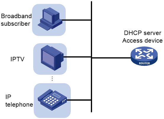
About this task
This feature enables the DHCP server to assign different gateway IP addresses to DHCP clients. In addition, the DHCP server uses the gateway IP addresses and the server's MAC address to reply to ARP requests from the clients.
As shown in Figure 8, the DHCP server is configured on the access device that provides access for clients of different service types, such as broadband, IPTV, and IP telephone. The clients of different types obtain IP addresses on different subnets. For the clients to access the network, the access interface typically has no IP address configured. You must bind the gateways to the DHCP server's MAC address when specifying gateways for the DHCP clients.
Restrictions and guidelines
|
|
CAUTION: To avoid forwarding failure, do not delete a gateway address from a gateway list if that gateway address is being used by online clients. |
If the IP pool is applied to a VPN instance, make sure the VPN instance exists for the specified list of gateways to take effect.
This feature is available only for common IP pools.
Procedure
1. Enter system view.
system-view
2. Enter IP pool view.
ip pool pool-name
3. Bind the gateways to the device's MAC address.
gateway-list ip-address&<1-64> export-route
By default, gateways are not bound to any MAC address.
Advertising network segments that are assigned to clients
About this task
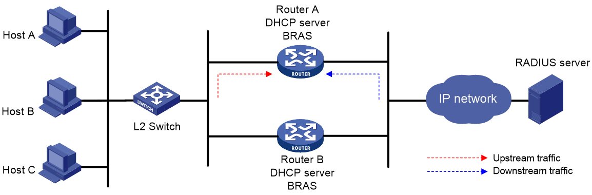
This feature enables the route management module to advertise network segments assigned to DHCP clients. This feature achieves symmetric routing for traffic of the same host.
As shown in Figure 9, Router A and Router B act as both the DHCP server and the BRAS device. The BRAS devices send accounting packets to the RADIUS server. To enable the BRAS devices to collect correct accounting information for each RADIUS user, configure the DHCP server to advertise network segments assigned to clients. The upstream and downstream traffic of a RADIUS user will pass through the same BRAS device.
Restrictions and guidelines
If the IP pool is applied to a VPN instance, make sure the VPN instance exists for the settings made in this task to take effect.
Procedure
1. Enter system view.
system-view
2. Create an IP pool and enter its view.
ip pool pool-name
3. Advertise network segments assigned to DHCP clients.
network network-address [ mask-length | mask mask ] [ secondary ] export-route [ preference preference | tag tag ] *
By default, the network segments assigned to DHCP clients are not advertised.
Enabling host route advertisement
About this task
The network export-route command enables the DHCP server to advertise the network route for each assigned IP address in the pool. If multiple pools share the same segment, the same network route will be advertised for assigned IP addresses in these pools. This will make the clients using these IP addresses inaccessible to external devices. To resolve this issue, enable host route advertisement for each IP pool to advertise a host route for each assigned IP address.
This feature does not affect the generation of host routes. When the DHCP server assigns an IP address in an address pool, it generates a host route for that IP address. However, this route cannot be advertised to other devices through routing protocols (such as BGP) by default. To resolve this issue, enable host route advertisement for the address pool:
· The device will delete the UNRs generated after the network export-route or gateway command is executed.
· After the device generates host routes for assigned IP addresses in the address pool, routing protocols can advertise those routes to other devices.
Restrictions and guidelines
Before you enable host route advertisement for an IP pool, make sure the IP pool has not assigned any IP addresses.
After you enable this feature for an IP pool, the DHCP server advertises only host routes. The network export-route command and the unr tag command will not take effect on the IP pool. They take effect only after you execute the undo export host-route command for the IP pool.
Procedure
1. Enter system view.
system-view
2. Enter IP pool view.
ip pool pool-name [ bas { local | remote } ]
3. Enable host route advertisement.
export host-route
By default, host route advertisement is disabled.
Enabling route logging for IP address pools
About this task
This feature enables the DHCP server to generate log entries for route events that occur in IP address pools. Route events include network route adding or deletion.
To enable route logging for an IP address pool, perform one of the following tasks:
· Use the dhcp route-log enable command in system view.
This command enables route logging for all types of IP address pools on the DHCP server.
· Use the route-log enable command in the view of the IP address pool.
This command enables route logging for a single IP address pool on the DHCP server.
Enabling route logging for all IP address pools
1. Enter system view.
system-view
2. Enable route logging for all IP address pools on the DHCP server.
dhcp route-log enable
By default, route logging is disabled for all IP address pools.
Enabling route logging for a single IP address pool
1. Enter system view.
system-view
2. Enter IP pool view.
ip pool pool-name [ bas { local | remote } ]
3. Enable route logging for an IP address pool on the DHCP server.
route-log enable
By default, route logging is disabled for an IP address pool.
Locking an IP address pool
About this task
You can lock an IP pool in loose mode or strict mode.
· If an IP pool is locked in loose mode, the server responds to the lease renewal requests from online DHCP clients for IP addresses in the pool. However, it does not assign IP addresses from the pool to new DHCP clients.
· If an IP pool is locked in strict mode, the server does not respond to the lease renewal requests from online DHCP clients for IP addresses in the pool or assign IP addresses from the pool to new DHCP clients.
Lock an IP pool in loose mode or strict mode depending on the IP pool management requirements.
· Lock an IP pool in loose mode if you are using that pool only to assign addresses to existing DHCP clients on the network.
· Lock an IP pool in strict mode if you are deleting or changing the IP space assigned to the IP pool. You can delete or change the IP space for an IP pool only when the IP pool does not contain assigned IP addresses. Locking the IP pool in strict mode ensures that you can perform the delete or change operation as soon as all assigned IP addresses in the pool are reclaimed.
Procedure
1. Enter system view.
system-view
2. Enter IP address pool view.
ip pool pool-name [ bas { local | remote } ]
3. Lock the IP address pool.
lock [ strict ]
By default, an IP address pool is not locked.
If you do not specify the strict keyword, the IP pool is locked in loose mode.
Configuring an IP pool group
About IP pool grouping
Application scenarios
On an AAA network, the AAA server allocates an IP address in the IP pool to a user after the user passes authentication. If only one IP pool is specified for address assignment, the following requirements cannot be met:
· The AAA server selects different DHCP servers for users in different locations.
· The AAA server acts as the DHCP server for address allocation, and also as a relay agent to forward DHCP requests and replies between DHCP clients and DHCP servers.
· Common IP pools and IP pools that support dynamic subnet allocation are required in a hybrid common and CUPS network.
To meet these requirements, add multiple IP pools (including common IP pools and remote BAS IP pools) to an IP pool group, and associate the IP pool group with the AAA server. The AAA server selects an IP address in the matching IP pool of the IP pool group. On a common network, you can add common IP pools and BAS IP pools to an IP pool group.
IP pool selection policy
An IP pool group can contain local IP pools and remote IP pools. By default, the server uses the remote IP pools in a pool group for dynamic allocation only when none of the local IP pools in that group have assignable addresses.
For a user that matches an IP pool group, the DHCP server selects an IP address from an available IP pool in the IP pool group in descending order of pool priority values. If multiple IP pools have the same priority, the server selects the pool displayed first in the output from the display ip pool-group command.
Round-robin IP pool selection
By default, the DHCP server moves from one IP pool to the next only when that IP pool does not have assignable IP addresses. This pool selection mechanism leads to uneven address resource distribution among IP pools. To balance resource usage across the IP pools in a pool group, enable the round-robin algorithm on that pool group.
The round-robin IP pool selection mechanism operates as follows:
1. On receipt of the first DHCP request, the server selects the first available IP pool for address allocation from the pool group.
2. When a new DHCP request arrives, the server selects the next available IP pool for address allocation.
3. After the server iterates through all the IP pool in the group, the server starts over again from the first IP pool.
You can enable the round-robin algorithm for selection of local IP pools, remote BAS IP pools, or both types of IP pools in a pool group.
If you enable the round-robin algorithm for both types of IP pools, the server will first select local IP pools in a round-robin manner. It moves to remote BAS IP pools for round-robin selection only if none of the local IP pools has assignable IP addresses.
Restrictions and guidelines
For roaming clients to obtain IP addresses correctly, make sure the IP pool group for these clients contains only local IP pools or remote BAS IP pools.
Procedure
1. Enter system view.
system-view
2. Create an IP pool and enter its view.
ip pool pool-name [ bas { local | remote } ]
By default, no IP pools exist on the device.
3. Create an IP pool group and enter its view.
ip pool-group group-name
By default, no IP pool groups exist on the device.
4. Add an IP pool to the IP pool group.
pool pool-name [ priority priority-value ]
By default, an IP pool does not belong to any IP pool group.
You can add only common IP pools and BAS IP pools to an IP pool group. The IP pool group and its pool members must belong to the same VPN instance.
5. (Optional.) Enable round-robin IP pool selection.
ip-pool algorithm round-robin { local | remote } *
By default, the DHCP server moves from one IP pool to the next only when that IP pool does not have assignable IP addresses.
6. (Optional.) Apply the IP pool group to a VPN instance.
vpn-instance vpn-instance-name
By default, an IP pool group is not applied to any VPN instance.
You cannot modify the VPN instance for an IP pool group if this IP pool group has been applied to a VPN instance.
Applying an IP pool to an interface
About this task
Upon receiving a DHCP request from the interface, the DHCP server performs address allocation in the following ways:
· If a static binding is found for the client, the server assigns the static IP address and configuration parameters from the IP pool that contains the static binding.
· If no static binding is found for the client, the server uses the IP pool applied to the interface for address and configuration parameter allocation.
Procedure
1. Enter system view.
system-view
2. Enter interface view.
interface interface-type interface-number
3. Apply an IP pool to the interface.
dhcp server apply ip-pool pool-name
By default, no IP pool is applied to an interface.
If the applied IP pool does not exist, the DHCP server fails to perform dynamic address allocation.
Configuring a DHCP policy for dynamic assignment
About this task
In a DHCP policy, each DHCP user class has a bound IP pool. Clients matching different user classes obtain IP addresses and other parameters from different IP pools. The DHCP policy must be applied to the interface that acts as the DHCP server. When receiving a DHCP request, the DHCP server compares the packet against the user classes in the order that they are configured.
· If a matching user class is found and the bound IP pool has assignable IP addresses, the server assigns an IP address and other parameters from the IP pool. If the IP pool does not have assignable IP addresses, the address assignment fails.
· If no match is found, the server assigns an IP address and other parameters from the default IP pool. If no default IP pool is specified or the default IP pool does not have assignable IP addresses, the address assignment fails.
For successful address assignment, make sure the applied DHCP policy and the bound IP pools exist.
Restrictions and guidelines
A DHCP policy take effect only after it is applied to an interface.
IP pools specified in DHCP policies can only be the IP pools that are created on the DHCP server.
Procedure
1. Enter system view.
system-view
2. Create a DHCP policy and enter DHCP policy view.
dhcp policy policy-name
3. Specify an IP pool for a DHCP user class.
class class-name ip-pool pool-name
By default, no IP pool is specified for a user class.
4. Specify the default IP pool.
default ip-pool pool-name
By default, no default IP pool is specified.
5. Return to system view.
quit
6. Enter interface view.
interface interface-type interface-number
7. Apply the DHCP policy to the interface.
dhcp apply-policy policy-name
By default, no DHCP policy is applied to an interface.
Enabling DHCP policy-first IP pool selection for IPoE users
About this task
After an IPoE user comes online, the device selects the AAA authorized IP pool for the user by default. This feature enables the DHCP server to select an IP pool for IPoE users in the following descending order:
1. IP pool specified for the DHCP user class that the IPoE users match.
2. IP pool authorized by AAA.
3. Default IP pool. If no default IP pool is specified or the default IP pool does not have assignable IP addresses, the address assignment fails.
For more information about the AAA authorized IP pool, see AAA configuration in BRAS Services Configuration Guide.
Restrictions and guidelines
You must determine the IP pool selection method before IPoE users come online. If you modify the selection method after IPoE users come online, the IPoE users that have obtained addresses cannot correctly extend the lease duration. When an address lease expires, the IPoE user goes offline, and the IPoE session is deleted.
Procedure
1. Enter system view.
system-view
2. Enter interface view.
interface interface-type interface-number
3. Enable DHCP policy-first IP pool selection for IPoE users.
dhcp server policy-first enable
By default, the device uses the AAA authorized IP pool for IPoE users.
Allocating different IP addresses to DHCP clients with the same MAC
About this task
Traditionally, the DHCP server identifies DHCP clients based on their MAC addresses. Each MAC address can be bound to only one IP address. However, DHCP clients that have the same MAC address exist in the network, and each client requires an IP address. You can enable this feature to allocate different IP addresses to such clients.
This feature enables the DHCP server to use the following methods to identify the DHCP clients that have the same MAC address:
· If a DHCP snooping device or a DHCP relay agent exists, you must enable the DHCP snooping device or the DHCP relay agent to support Option 82. The DHCP server identifies a DHCP client by the MAC address of the client and the Option 82 in the DHCP request.
· If no DHCP snooping device or DHCP relay agent is on the network, the DHCP server identifies a DHCP client by the combination of the following information:
¡ The MAC address of the client.
¡ The interface name in the DHCP request.
¡ The VLAN information of the receiving interface.
Restrictions and guidelines
This feature does not take effect in PPPoE networks.
Do not configure the dhcp server multi-ip per-mac enable command in conjunction with the dhcp session-mismatch action command.
Procedure
1. Enter system view.
system-view
2. Enable allocation of different IP addresses to DHCP clients with the same MAC address.
dhcp server multi-ip per-mac enable
By default, allocation of different IP addresses to DHCP clients with the same MAC address is disabled.
Enabling DHCP
Restrictions and guideline
You must enable DHCP to make other DHCP configurations take effect.
Procedure
1. Enter system view.
system-view
2. Enable DHCP.
dhcp enable
By default, DHCP is disabled.
Enabling the DHCP server on an interface
About this task
Perform this task to enable the DHCP server on an interface. Upon receiving a DHCP request on the interface, the DHCP server assigns the client an IP address and other configuration parameters from an IP pool.
Procedure
1. Enter system view.
system-view
2. Enter interface view.
interface interface-type interface-number
3. Enable the DHCP server on the interface.
dhcp select server
By default, the DHCP server is enabled on the interface.
Configuring IP address conflict detection
About this task
Before assigning an IP address, the DHCP server pings that IP address.
· If the server receives a response within the specified period, it selects and pings another IP address.
· If it receives no response, the server continues to ping the IP address until the maximum number of ping packets are sent. If still no response is received, the server assigns the IP address to the requesting client. The DHCP client uses gratuitous ARP to perform IP address conflict detection.
Procedure
1. Enter system view.
system-view
2. (Optional.) Set the maximum number of ping packets to be sent for conflict detection.
dhcp server ping packets number
The default setting is one.
To disable IP address conflict detection, set the value to 0.
3. (Optional.) Set the ping timeout time.
dhcp server ping timeout milliseconds
The default setting is 500 milliseconds.
To disable IP address conflict detection, set the value to 0.
Enabling handling of Option 82
About this task
Perform this task to enable the DHCP server to handle Option 82. Upon receiving a DHCP request that contains Option 82, the DHCP server adds Option 82 into the DHCP response.
If you disable the DHCP to handle Option 82, it does not add Option 82 into the response message.
You must enable handling of Option 82 on both the DHCP server and the DHCP relay agent to ensure correct processing for Option 82. For information about enabling handling of Option 82 on the DHCP relay agent, see "Configuring DHCP relay agent support for Option 82."
Procedure
1. Enter system view.
system-view
2. Enable the server to handle Option 82.
dhcp server relay information enable
By default, handling of Option 82 is enabled.
Configuring the DHCP server security features
Restrictions and guidelines for DHCP server security feature configuration
The DHCP server security features are not applicable if a DHCP relay agent exists in the network. This is because the MAC address of the DHCP relay agent is encapsulated as the source MAC address in the DHCP request received by the DHCP server. In this case, you must configure the DHCP relay agent security features. For more information, see "Configuring the DHCP relay agent security features."
Configuring DHCP flood attack protection
About this task
The DHCP flood attack protection enables the DHCP server to detect DHCP flood attacks according to the DHCP packet rate threshold on a per-MAC basis.
When the DHCP server receives a DHCP packet from a client (MAC address), it creates a DHCP flood attack protection entry in check state. If the number of incoming DHCP packets from the same MAC address reaches the upper limit in the detection duration, the server determines that the client is launching a DHCP flood attack. The DHCP flood attack protection entry changes to the restrain state, and the DHCP server discards the DHCP packets from that client. When the aging time of the entry is reached, the DHCP server examines the drop rate of DHCP packets sent from the MAC address.
· If the packet drop rate is lower than the DHCP flood attack threshold, the DHCP server deletes the entry. If later a DHCP packet from that MAC address arrives, the DHCP server will create a new flood attack protection entry and count the number of incoming DHCP packets for that client again.
· If the packet drop rate is equal to or higher than the DHCP flood attack threshold, the DHCP server resets the aging time for the entry.
DHCP flood attack protection takes effect on all interfaces if it is enabled globally. To enable DHCP flood attack protection on only some of the interfaces, disable the feature globally and enable it on the desired interfaces.
Procedure
1. Enter system view.
system-view
2. (Optional.) Set the DHCP packet rate threshold for triggering DHCP flood attack protection.
dhcp flood-protection threshold packet-number milliseconds
By default, the device allows a maximum of 10 DHCP packets per 5000 milliseconds from each DHCP client.
3. (Optional.) Set the aging time of DHCP flood attack protection entries.
dhcp flood-protection aging-time time
The default setting is 300 seconds.
4. Enable DHCP flood attack protection globally.
dhcp flood-protection global enable
By default, DHCP flood attack protection is disabled globally.
5. Enable DHCP flood attack protection only on one interface.
a. Disable DHCP flood attack protection globally.
undo dhcp flood-protection global enable
By default, DHCP flood attack protection is disabled globally.
b. Enter interface view.
interface interface-type interface-number
c. Enable DHCP flood attack protection on the interface.
dhcp flood-protection enable
By default, DHCP flood attack protection is disabled on interfaces.
Configuring DHCP starvation attack protection
About this task
A DHCP starvation attack occurs when an attacker constantly sends forged DHCP requests using different MAC addresses in the chaddr field to a DHCP server. This exhausts the IP address resources of the DHCP server so legitimate DHCP clients cannot obtain IP addresses. The DHCP server might also fail to work because of exhaustion of system resources. For information about the fields in the DHCP messages, see "DHCP message format."
The following methods are available to relieve or prevent such attacks.
· To relieve a DHCP starvation attack that uses DHCP packets encapsulated with different source MAC addresses, perform the following configuration on an interface:
¡ Execute the mac-address max-mac-count command to set the MAC learning limit. For more information about this command, see Layer 2—LAN Switching Command Reference.
¡ Disable unknown frame forwarding when the MAC learning limit is reached.
· To prevent a DHCP starvation attack that uses DHCP requests encapsulated with the same source MAC address, you can enable MAC address check on the DHCP server. The DHCP server compares the chaddr field of a received DHCP request with the source MAC address in the frame header. If they are the same, the DHCP server verifies this request as legal and processes it. If they are not the same, the server discards the DHCP request.
Restrictions and guidelines
This feature only checks whether the chaddr field of a received DHCP-DISCOVER message is the same as the source MAC address in the frame header.
Procedure
1. Enter system view.
system-view
2. Enter interface view.
interface interface-type interface-number
3. Enable MAC address check.
dhcp server check mac-address
By default, MAC address check is disabled.
Configuring interface-based DHCP attack suppression
About this task
DHCP attack suppression protects an interface from DHCP attacks by limiting the rate of incoming DHCP packets after the specified threshold is crossed.
When an interface protected with DHCP attack suppression receives a DHCP packet, the DHCP server creates a DHCP attack suppression entry in check state for the interface. If the incoming DHCP packet rate on the interface reaches the threshold, a DHCP attack occurs on the interface. The suppression entry changes to the restrain state. To protect the CPU against DHCP attack packets, the device limits the incoming DHCP packet rate on the interface before the aging time of the suppression entry is reached.
When the aging time of the DHCP attack suppression entry on an interface is reached, the device examines the incoming DHCP packet rate on the interface.
· If the incoming packet rate is below the suppression threshold, the device deletes the entry. When a new DHCP packet arrives on that interface, the DHCP server creates a new attack suppression entry and starts to count the number of incoming DHCP packets on that interface again.
· If the incoming packet rate is above the suppression threshold, the device resets the aging timer.
Restrictions and guidelines
You can enable DHCP attack suppression globally or on a per-interface basis.
· To enable DHCP attack suppression on all interfaces, enable it globally.
· DHCP attack suppression takes effect on an interface as long as it is enabled globally or on the interface. To suppress DHCP attacks only on some of the interfaces, you must disable DHCP attack suppression globally, and then enable the feature on the target interfaces.
Procedure
1. Enter system view.
system-view
2. (Optional.) Set the DHCP packet rate threshold for triggering interface-based DHCP attack suppression.
dhcp interface-rate-suppression threshold packet-number milliseconds
By default, the DHCP server can receive a maximum of 3000 DHCP packets per 5000 milliseconds on an interface.
3. (Optional.) Set the aging time of interface-based DHCP attack suppression entries.
dhcp interface-rate-suppression aging-time time
The default setting is 300 seconds.
4. Enable DHCP attack suppression.
¡ To enable DHCP attack suppression on all interfaces:
dhcp interface-rate-suppression global enable
By default, global DHCP attack suppression is disabled.
¡ To enable DHCP attack suppression only on some of the interfaces:
i Disable global DHCP attack suppresion if it has been enabled.
undo dhcp interface-rate-suppression global enable
ii Enter interface view.
interface interface-type interface-number
iii Enable DHCP attack suppression on the interface.
dhcp interface-rate-suppression enable
By default, DHCP attack suppression is disabled on interfaces.
Configuring DHCP server compatibility
Perform this task to enable the DHCP server to support DHCP clients that are incompliant with RFC.
Configuring the DHCP server to always broadcast responses
About this task
By default, the DHCP server broadcasts a response only when the broadcast flag in the DHCP request is set to 1. You can configure the DHCP server to ignore the broadcast flag and always broadcast a response. This feature is useful when some clients set the broadcast flag to 0 but do not accept unicast responses.
The DHCP server always unicasts a response in the following situations, regardless of whether this feature is configured or not:
· The DHCP request is from a DHCP client that has an IP address (the ciaddr field is not 0).
· The DHCP request is forwarded by a DHCP relay agent from a DHCP client (the giaddr field is not 0).
Procedure
1. Enter system view.
system-view
2. Enable the DHCP server to always broadcast all responses.
dhcp server always-broadcast
By default, the DHCP server reads the broadcast flag to decide whether to broadcast or unicast a response.
Disabling Option 60 encapsulation in DHCP replies
About this task
If one or more DHCP clients cannot resolve Option 60, disable the DHCP server from encapsulating Option 60 in DHCP replies. If you do not disable the capability, the DHCP server encapsulates Option 60 in a DHCP reply in the following situations:
· The received DHCP packet contains Option 60.
· Option 60 is configured for the IP pool.
Procedure
1. Enter system view.
system-view
2. Disable the DHCP server from encapsulating Option 60 in DHCP replies.
dhcp server reply-exclude-option60
By default, the DHCP server can encapsulate Option 60 in DHCP replies.
Enabling the DHCP server to return a DHCP-NAK message upon client notions of incorrect IP addresses
About this task
A DHCP client can send a DHCPREQUEST message directly or upon receiving a DHCP-OFFER message. Upon receiving the request, the DHCP server will check if the client notion of its IP address is correct. If the requested IP address is different from the allocated one or has no matching lease record, the DHCP server remains silent by default. After the allocated IP address lease for the client expires, the DHCP server will make response to request from the client.
This feature enables the DHCP server to return DHCP-NAK messages if the client notions of their IP addresses are incorrect. After receiving the DHCP-NAK message, the DHCP client will request an IP address again.
Procedure
1. Enter system view.
system-view
2. Enable the DHCP server to return a DHCP-NAK message if the client notions of their IP addresses are incorrect.
dhcp server request-ip-address check
By default, the DHCP server does not return a DHCP-NAK message if the client notions of their IP addresses are incorrect.
Configuring the DHCP server to ignore BOOTP requests
About this task
The lease duration of the IP addresses obtained by the BOOTP clients is unlimited. For some scenarios that do not allow unlimited leases, you can configure the DHCP server to ignore BOOTP requests.
Procedure
1. Enter system view.
system-view
2. Configure the DHCP server to ignore BOOTP requests.
dhcp server bootp ignore
By default, the DHCP server processes BOOTP requests.
Configuring the DHCP server to send BOOTP responses in RFC 1048 format
About this task
Not all BOOTP clients can send requests that are compatible with RFC 1048. By default, the DHCP server does not process the Vend field of RFC 1048-incompliant requests but copies the Vend field into responses.
This feature enables the DHCP server to fill the Vend field in RFC 1048-compliant format in DHCP responses to RFC 1048-incompliant requests sent by BOOTP clients.
Procedure
1. Enter system view.
system-view
2. Enable the DHCP server to send BOOTP responses in RFC 1048 format to the RFC 1048-incompliant BOOTP requests.
dhcp server bootp reply-rfc-1048
By default, the DHCP server directly copies the Vend field of such requests into the responses.
Setting the DSCP value for DHCP packets sent by the DHCP server
About this task
The DSCP value of a packet specifies the priority level of the packet and affects the transmission priority of the packet.
Procedure
1. Enter system view.
system-view
2. Set the DSCP value for DHCP packets sent by the DHCP server.
dhcp dscp dscp-value
By default, the DSCP value in DHCP packets sent by the DHCP server is 56.
Configuring DHCP packet rate limit on a DHCP server interface
About this task
With this feature enabled on the DHCP server interface, the interface discards DHCP packets that exceed the maximum rate.
Procedure
1. Enter system view.
system-view
2. Enter interface view.
interface interface-type interface-number
3. Enable DHCP packet rate limit on an interface and set the limit value.
dhcp rate-limit rate
By default, DHCP packet rate limit is disabled on an interface.
Configuring DHCP binding auto backup
About this task
The auto backup feature saves bindings to a backup file and allows the DHCP server to download the bindings from the backup file at the server reboot. The bindings include the lease bindings and conflicted IP addresses. They cannot survive a reboot on the DHCP server.
The DHCP server does not provide services during the download process. If a connection error occurs during the process and cannot be repaired in a short amount of time, you can terminate the download operation. Manual interruption allows the DHCP server to provide services without waiting for the connection to be repaired.
Procedure
1. Enter system view.
system-view
2. Configure the DHCP server to back up the bindings to a file.
dhcp server database filename { filename | url url [ username username [ password { cipher | simple } string ] ] }
By default, the DHCP server does not back up the DHCP bindings.
With this command executed, the DHCP server backs up its bindings immediately and runs auto backup.
3. (Optional.) Manually save the DHCP bindings to the backup file.
dhcp server database update now
4. (Optional.) Set the waiting time after a DHCP binding change for the DHCP server to update the backup file.
dhcp server database update interval interval
By default, the DHCP server waits 300 seconds to update the backup file after a DHCP binding change. If no DHCP binding changes, the backup file is not updated.
5. (Optional.) Terminate the download of DHCP bindings from the backup file.
dhcp server database update stop
This command only triggers one termination.
Enabling client offline detection on the DHCP server
About this task
The client offline detection feature reclaims an assigned IP address and deletes the binding entry when the ARP entry for the IP address ages out.
Restrictions and guidelines
The feature does not function if an ARP entry is manually deleted.
Procedure
1. Enter system view.
system-view
2. Enter interface view.
interface interface-type interface-number
3. Enable client offline detection.
dhcp client-detect
By default, client offline detection is disabled on the DHCP server.
Enabling the IP conflicting user offline feature
About this task
IP address conflict occurs when the IP address assigned by the authentication and authorization module to a new user is the same as the IP address of an online DHCP client. By default, the conflicting online DHCP client still stays online, and the new user cannot come online.
This feature enables the server to release the conflicting IP address when an IP conflict occurs, and informs the access module that the address is not available. Both the online user and requesting users are offline. It ensures that a new user can obtain an IP address next time the user request the IP address through DHCP.
Procedure
1. Enter system view.
system-view
2. Enable the IP conflicting user offline feature.
dhcp conflict-ip-address offline
By default, the IP conflicting user offline feature is disabled. When the IP address assigned to a new DHCP client conflicts with the IP address of an online DHCP client, the online DHCP client still stays online.
Specifying a DHCP request processing method for roaming DHCP clients
About this task
When a DHCP client roams in a network, the client sends an offline request to the DHCP server before requesting a new address. If the DHCP server does not receive the offline request, it will discard the DHCP client's new address request because it determines that the request is an attack packet.
This feature allows the DHCP server to process address requests as follows upon receiving them from roaming DHCP clients:
· The fast-renew method enables the server to release existing address leases of roaming clients and assign them new IP addresses.
· The roam method enables the server to assign addresses to clients based on their existing address leases and renew the leases. The clients can use the original IP addresses to access the network without another authentication.
Restrictions and guidelines
This feature is applicable to only IPoE networks.
The roam keyword in the dhcp session-mismatch action { fast-renew | roam } command can take effect only after you enable roaming for IPoE individual users by using the ip subscriber roaming enable command.
For more information about IPoE roaming, see IPoE configuration in BRAS Services Configuration Guide.
Do not configure the dhcp session-mismatch action command in conjunction with the dhcp server multi-ip per-mac enable command.
Procedure
1. Enter system view.
system-view
2. Enter interface view.
interface interface-type interface-number
3. Specify a method for the DHCP server to process address requests of roaming clients.
dhcp session-mismatch action { fast-renew | roam }
By default, the DHCP server discards DHCP address requests sent from roaming DHCP clients.
Releasing the lease of a client that comes online from an authentication domain different from its previous domain
About this task
When a client goes offline, the DHCP server might not be aware of the offline event and cannot release the client lease timely. If the client comes online again from a different authentication domain, information in Options 16, 17, and 60 in the DHCP request sent by the client will change. If the DHCP server returns the IP address in the existing lease to the client without parsing Option information in the request, the client will be unable to access the network. This is because the obtained IP address does not match the new authentication domain.
To resolve this issue, you can enable this feature. The DHCP server will perform the following tasks when it receives an IP address request from a client that already has a lease:
· Release the existing IP address lease for that client.
· Ignore the IP address request.
After the wait timer for DHCP server response expires, the client will resend an IP address request. On receipt of the request, the DHCP server will select a correct IP pool based on the Option information and assign a new IP address to the client.
Procedure
1. Enter system view.
system-view
2. Enable the DHCP server to release the existing IP address lease for a client when it receives an IP address request from that client again. Choose one option as needed.
¡ DHCPDISCOVER message:
dhcp authorized-ip-conflict ignore
By default, the DHCP server returns the IP address in the existing lease for a client when it receives a DHCPDISCOVER message from that client again.
¡ DHCPREQUEST message sent on reboot:
dhcp reboot-request user offline
By default, the DHCP server returns the IP address in the existing lease for a client when it receives a DHCPREQUEST message sent on reboot from that client again.
Configuring SNMP notifications for the DHCP server
About SNMP DHCP server notifications
Perform this task to configure the device to send SNMP notifications of DHCP server alarms. Example DHCP server alarm notifications include the following:
· IP exhaustion notifications—All assignable IP addresses in an IP pool are used up or an IP pool has recovered from an IP exhaustion condition.
· IP allocation alarm notifications—The IP allocation success rates of all IP pools on the server are lowered than the specified IP allocation success rate threshold.
· IP usage alarm notifications—The IP address usage of an IP pool has reached or exceeded the specified threshold, or an IP pool has recovered from an IP usage alarm condition.
The SNMP notifications are sent to the SNMP module. For the SNMP notifications to be sent correctly, you must also configure SNMP. For more information about SNMP configuration, see Network Management and Monitoring Configuration Guide.
When the IP pool usage reaches or exceeds the threshold or drops below 90% of the threshold, the DHCP module sends a log message to the information center. For log messages to be sent correctly, you must also configure the information center. For information about configuring the information center, see Network Management and Monitoring Configuration Guide.
Enabling IP exhaustion notifications
system-view
2. Enable IP exhaustion notifications.
snmp-agent trap enable dhcp server address-exhaust
By default, IP exhaustion notifications are enabled.
3. Enter IP address pool view.
ip pool pool-name [ bas { local | remote } ]
4. Enable IP exhaustion notifications for an IP pool.
exhaustion trap enable
By default, IP exhaustion notifications are enabled for an IP pool.
Enabling IP allocation alarm notifications
1. Enter system view.
system-view
2. Enable IP allocation alarm notifications.
snmp-agent trap enable dhcp server allocated-ip
By default, IP allocation alarm notifications are enabled.
3. (Optional.) Set the IP allocation success rate threshold.
dhcp server allocated-ip threshold threshold-value
By default, no IP allocation success rate threshold is set. The device does not generate IP allocation alarm notifications.
Enabling IP allocation failure alarming
1. Enter system view.
system-view
2. Enable IP allocation failure alarming.
snmp-agent trap enable dhcp server ip-alloc-failed
By default, IP allocation failure alarming is enabled.
Enabling IP usage alarm notifications
1. Enter system view.
system-view
2. Enable IP usage alarm notifications.
snmp-agent trap enable dhcp server ip-in-use
By default, IP usage alarm notifications are enabled.
3. Enter IP pool view.
ip pool pool-name [ bas { local | remote } ]
4. (Optional.) Set the IP address usage threshold for the IP pool.
ip-in-use threshold threshold-value
The default IP address usage threshold is 100%.
Enabling IP resource exhaustion alarming for IP pool groups
About this task
To enable IP resource exhaustion alarming for an IP pool group, use one of the following methods:
· Use the snmp-agent trap enable dhcp server pool-group-exhaust command in system view to enable IP resource exhaustion alarming for all IP pool groups.
· Use the exhaustion trap enable command in the view of the IP pool group to enable IP resource exhaustion alarming for the IP pool group.
Restrictions and guidelines
For the exhaustion trap enable command to take effect, enable IP resource exhaustion alarming for all IP pool groups first.
After you enable IP resource exhaustion alarming for all IP pool groups, a large number of unnecessary alarm notifications might be generated. To reduce the number of unnecessary alarm notifications, disable IP resource exhaustion alarming for some IP pools by using the undo exhaustion trap enable command.
Procedure
1. Enter system view.
system-view
2. Enable address exhaustion alarming for IP pool groups.
snmp-agent trap enable dhcp server pool-group-exhaust
By default, address exhaustion alarming is enabled for IP pool groups.
3. Enter IP pool group view.
ip pool-group pool-group-name
4. (Optional.) Enable IP resource exhaustion alarming for the IP pool group.
exhaustion trap enable
By default, IP resource exhaustion alarming is enabled for an IP pool group.
Enabling IP address resource usage alarming for IP pool groups
1. Enter system view.
system-view
2. Enable IP address resource usage alarming for IP pool groups.
snmp-agent trap enable dhcp server pool-group-threshold
By default, IP resource usage alarming is enabled for IP pool groups.
3. Enter IP pool group view.
ip pool-group pool-group-name
4. (Optional.) Set the IP address usage threshold for the IP pool group.
ip-in-use threshold threshold-value
The default IP address usage threshold is 100%.
Enabling DHCP logging on the DHCP server
About this task
The DHCP logging feature enables the DHCP server to generate DHCP logs and send them to the information center. For information about the log destination and output rule configuration in the information center, see Network Management and Monitoring Configuration Guide.
Restrictions and guidelines
As a best practice, disable this feature if the log generation affects the device performance or reduces the address allocation efficiency. For example, this situation might occur when a large number of clients frequently come online or go offline.
Procedure
1. Enter system view.
system-view
2. Enable DHCP logging.
dhcp log enable
By default, DHCP logging is disabled.
Enabling IP resource exhaustion logging
About this task
This feature enables the DHCP module to send IP resource exhaustion event logs to the information center.
IP resource exhaustion events include IP resource exhaustion alarms and recoveries from IP resource exhaustion alarm conditions.
An IP resource exhaustion log is generated for an IP pool or IP pool group when one of the following events occurs:
· The IP pool or IP pool group does not have assignable IP addresses or subnets.
· In a non-CUPS scenario, the IP address usage of the IP pool or IP pool group drops below 90% after IP address exhaustion. The IP address usage is calculated by using the following formula:
(Total number of IP addresses – number of assignable IP addresses)/total number of IP addresses
For log messages to be sent correctly, you must also configure the information center. For information about the information center configuration, see Network Management and Monitoring Configuration Guide.
Restrictions and guidelines
This feature is not affected if DHCP logging is disabled on the DHCP server.
Enabling IP resource exhaustion logging for an IP pool
1. Enter system view.
system-view
2. Enter IP pool view.
ip pool pool-name [ bas { local | remote } ]
3. Enable IP resource exhaustion logging.
exhaustion log enable
By default, IP resource exhaustion logging is disabled.
Enabling IP resource exhaustion logging for an IP pool group
1. Enter system view.
system-view
ip pool-group pool-group-name
3. Enable IP resource exhaustion logging.
exhaustion log enable
By default, IP resource exhaustion logging is disabled.
Display and maintenance commands for DHCP server
|
|
IMPORTANT: A restart of the DHCP server or execution of the reset dhcp server ip-in-use command deletes all lease information. The DHCP server denies any DHCP request for lease extension, and the client must request an IP address again. |
Execute display commands in any view and reset commands in user view.
|
Task |
Command |
|
Display information about DHCP flood attack entries. |
display dhcp flood-protection slot slot-number [ mac-address mac-address [ interface interface-type interface-number ] | state { check | restrain } [ verbose ] | statistics | verbose ] |
|
Display information about interface-based DHCP attack suppression entries. |
display dhcp interface-rate-suppression slot slot-number [ interface interface-type interface-number | state { check | restrain } [ verbose ] | statistics | verbose ] |
|
Display address usage information for an IP pool group. |
display dhcp pool-group-usage [ pool-group pool-group-name ] |
|
display dhcp pool-usage [ peak ] [ pool pool-name ] |
|
|
Display packet statistics for the DHCP packet rate-limiting feature. |
display dhcp rate-limit slot slot-number |
|
Display information about IP address conflicts. |
display dhcp server conflict [ interface interface-type interface-number | ip ip-address | vxlan vxlan-id ] [ vpn-instance vpn-instance-name ] |
|
Display information about DHCP binding auto backup. |
display dhcp server database |
|
Display information about lease-expired IP addresses. |
display dhcp server expired [ [ interface interface-type interface-number | ip ip-address | mac mac-address | vxlan vxlan-id ] [ vpn-instance vpn-instance-name ] | pool pool-name ] [ verbose ] |
|
Display information about assignable IP addresses. |
display dhcp server free-ip [ pool pool-name | vpn-instance vpn-instance-name ] |
|
Display information about assigned IP addresses. |
display dhcp server ip-in-use [ [ interface interface-type interface-number | ip ip-address | subnet network-address mask-length | vxlan vxlan-id ] [ vpn-instance vpn-instance-name ] | pool pool-name | pool-group pool-group-name ] |
|
Display IP pool statistics on the DHCP server. |
display dhcp server statistics [ pool pool-name | vpn-instance vpn-instance-name ] |
|
Display the number of DHCP access users. |
display dhcp-access count |
|
Display packet statistics for the DHCP access module. |
display dhcp-access packet statistics |
|
Display information about DHCP access users. |
display dhcp-access user-table [ index index-value | mac-address mac-address | user-id user-id ] |
|
Display information about IP pools. |
display ip pool [ all | name pool-name | pool-group pool-group-name | [ vpn-instance vpn-instance-name ] [ bas { local | remote } ] ] [ verbose ] |
|
Display information about IP pool groups. |
display ip pool-group [ all | [ name pool-group-name ] [ vpn-instance vpn-instance-name ] ] [ verbose ] |
|
Delete DHCP flood attack protection entries. |
reset dhcp flood-protection slot slot-number [ mac-address mac-address [ interface interface-type interface-number ] ] [ packet-statistics ] |
|
Delete interface-based DHCP attack suppression entries. |
reset dhcp interface-rate-suppression slot slot-number [ interface interface-type interface-number ] [ packet-statistics ] |
|
Clear peak address usage information for an IP pool. |
reset dhcp pool-usage peak [ pool pool-name ] |
|
Clear packet statistics for the DHCP packet rate-limiting feature. |
reset dhcp rate-limit slot slot-number |
|
Clear information about IP address conflicts. |
reset dhcp server conflict [ ip start-ip-address [ end-ip-address ] ] [ vpn-instance vpn-instance-name ] |
|
Clear information about lease-expired IP addresses. |
reset dhcp server expired [ [ ip start-ip-address [ end-ip-address ] ] [ vpn-instance vpn-instance-name ] | pool pool-name ] |
|
Clear information about assigned IP addresses. |
reset dhcp server ip-in-use [ [ ip start-ip-address [ end-ip-address ] | relay-address ip-address ] [ vpn-instance vpn-instance-name ] | pool pool-name [ relay-address ip-address ] ] |
|
Clear DHCP server packet statistics. |
reset dhcp server packet statistics [ vpn-instance vpn-instance-name ] |
|
Clear packet statistics for the DHCP access module. |
reset dhcp-access packet statistics |
DHCP server configuration examples
Example: Configuring static IP address assignment
Network configuration
As shown in Figure 10, Router A (DHCP server) assigns a static IP address, a DNS server address, and a gateway address to Router B (DHCP client) and Router C (BOOTP client).
The client ID of the interface Ten-GigabitEthernet 3/0/1 on Router B is 0030-3030-662e-6532-3030-2e30-3030-322d-4574-6865-726e-6574.
The MAC address of the interface Ten-GigabitEthernet 3/0/1 on Router C is 000f-e200-01c0.
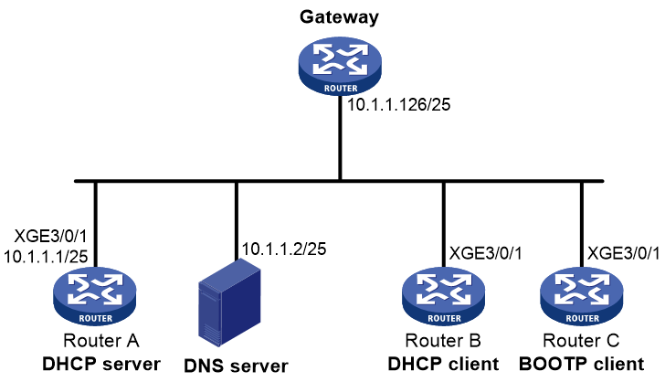
Procedure
1. Specify an IP address for Ten-GigabitEthernet 3/0/1 on Router A.
<RouterA> system-view
[RouterA] interface ten-gigabitethernet 3/0/1
[RouterA-Ten-GigabitEthernet3/0/1] ip address 10.1.1.1 25
[RouterA-Ten-GigabitEthernet3/0/1] quit
2. Configure the DHCP server:
# Create IP pool 0.
[RouterA] ip pool 0
# Configure a static binding for Router B.
[RouterA-ip-pool-0] static-bind ip-address 10.1.1.5 25 client-identifier 0030-3030-662e-6532-3030-2e30-3030-322d-4574-6865-726e-6574
# Configure a static binding for Router C.
[RouterA-ip-pool-0] static-bind ip-address 10.1.1.6 25 hardware-address 000f-e200-01c0
# Specify the DNS server address and the gateway address.
[RouterA-ip-pool-0] dns-list 10.1.1.2
[RouterA-ip-pool-0] gateway-list 10.1.1.126
[RouterA-ip-pool-0] quit
[RouterA]
# Enable DHCP.
[RouterA] dhcp enable
# Enable the DHCP server on Ten-GigabitEthernet 3/0/1.
[RouterA] interface ten-gigabitethernet 3/0/1
[RouterA-Ten-GigabitEthernet3/0/1] dhcp select server
[RouterA-Ten-GigabitEthernet3/0/1] quit
Verifying the configuration
# Verify that Router B can obtain IP address 10.1.1.5 and all other network parameters from Router A. (Details not shown.)
# Verify that Router C can obtain IP address 10.1.1.6 and all other network parameters from Router A. (Details not shown.)
# On the DHCP server, display the IP addresses assigned to the clients.
[RouterA] display dhcp server ip-in-use
IP address Client-identifier/ Lease expiration Type
Hardware address
10.1.1.5 0030-3030-662e-6532- Jan 21 14:27:27 2019 Static(C)
3030-2e30-3030-322d-
4574-6865-726e-6574
10.1.1.6 000f-e200-01c0 Unlimited Static(C)
Example: Configuring dynamic IP address assignment
Network configuration
As shown in Figure 11, the DHCP server (Router A) assigns IP addresses to clients on subnet 10.1.1.0/24, which is subnetted into 10.1.1.0/25 and 10.1.1.128/25.
Configure DHCP server on Router A to implement the following assignment scheme.
Table 2 Assignment scheme
|
DHCP clients |
IP address |
Lease |
Other configuration parameters |
|
Clients connected to Ten-GigabitEthernet 3/0/1 |
IP addresses on subnet 10.1.1.0/25 |
10 days and 12 hours |
· Gateway: 10.1.1.126/25 · DNS server: 10.1.1.2/25 · Domain name: aabbcc.com · WINS server: 10.1.1.4/25 |
|
Clients connected to Ten-GigabitEthernet 3/0/2 |
IP addresses on subnet 10.1.1.128/25 |
Five days |
· Gateway: 10.1.1.254/25 · DNS server: 10.1.1.2/25 · Domain name: aabbcc.com |

Procedure
1. Specify IP addresses for interfaces. (Details not shown.)
2. Configure the DHCP server:
# Exclude the IP addresses of the DNS server, WINS server, and gateways from dynamic allocation.
<RouterA> system-view
[RouterA] dhcp server forbidden-ip 10.1.1.2
[RouterA] dhcp server forbidden-ip 10.1.1.4
[RouterA] dhcp server forbidden-ip 10.1.1.126
[RouterA] dhcp server forbidden-ip 10.1.1.254
# Configure IP pool 1 to assign IP addresses and other configuration parameters to clients on subnet 10.1.1.0/25.
[RouterA] ip pool 1
[RouterA-ip-pool-1] network 10.1.1.0 mask 255.255.255.128
[RouterA-ip-pool-1] expired day 10 hour 12
[RouterA-ip-pool-1] domain-name aabbcc.com
[RouterA-ip-pool-1] dns-list 10.1.1.2
[RouterA-ip-pool-1] gateway-list 10.1.1.126
[RouterA-ip-pool-1] nbns-list 10.1.1.4
[RouterA-ip-pool-1] quit
# Configure IP pool 2 to assign IP addresses and other configuration parameters to clients on subnet 10.1.1.128/25.
[RouterA] ip pool 2
[RouterA-ip-pool-2] network 10.1.1.128 mask 255.255.255.128
[RouterA-ip-pool-2] expired day 5
[RouterA-ip-pool-2] domain-name aabbcc.com
[RouterA-ip-pool-2] dns-list 10.1.1.2
[RouterA-ip-pool-2] gateway-list 10.1.1.254
[RouterA-ip-pool-2] quit
# Enable DHCP.
[RouterA] dhcp enable
# Enable the DHCP server on Ten-GigabitEthernet 3/0/1 and Ten-GigabitEthernet 3/0/2.
[RouterA] interface ten-gigabitethernet 3/0/1
[RouterA-Ten-GigabitEthernet3/0/1] dhcp select server
[RouterA-Ten-GigabitEthernet3/0/1] quit
[RouterA] interface ten-gigabitethernet 3/0/2
[RouterA-Ten-GigabitEthernet3/0/2] dhcp select server
[RouterA-Ten-GigabitEthernet3/0/2] quit
Verifying the configuration
# Verify that clients on subnets 10.1.1.0/25 and 10.1.1.128/25 can obtain correct IP addresses and all other network parameters from Router A. (Details not shown.)
# On the DHCP server, display the IP addresses assigned to the clients.
[RouterA] display dhcp server ip-in-use
IP address Client-identifier/ Lease expiration Type
Hardware address
10.1.1.3 0031-3865-392e-6262- Jan 14 22:25:03 2015 Auto(C)
3363-2e30-3230-352d-
4745-302f-30
10.1.1.5 0031-fe65-4203-7e02- Jan 14 22:25:03 2015 Auto(C)
3063-5b30-3230-4702-
620e-712f-5e
10.1.1.130 3030-3030-2e30-3030- Jan 9 10:45:11 2015 Auto(C)
662e-3030-3033-2d45-
7568-6572-1e
10.1.1.131 3030-0020-fe02-3020- Jan 9 10:45:11 2015 Auto(C)
7052-0201-2013-1e02
0201-9068-23
10.1.1.132 2020-1220-1102-3021- Jan 9 10:45:11 2015 Auto(C)
7e52-0211-2025-3402
0201-9068-9a
10.1.1.133 2021-d012-0202-4221- Jan 9 10:45:11 2015 Auto(C)
8852-0203-2022-55e0
3921-0104-31
Example: Configuring DHCP user class
Network configuration
As shown in Figure 12, the DHCP relay agent (Router A) forwards DHCP packets between DHCP clients and the DHCP server (Router B). Enable Router A to handle Option 82 so that it can add Option 82 in DHCP requests and then forward them to the DHCP server.
Configure the address allocation scheme as follows:
|
Assign IP addresses |
To clients |
|
10.10.1.2 to 10.10.1.10 |
The DHCP request contains Option 82. |
|
10.10.1.11 to 10.10.1.26 |
The hardware address in the request is six bytes long and begins with aabb-aabb-aab. |
Router B assigns the DNS server address 10.10.1.20/24 and the gateway address 10.10.1.254/24 to clients on subnet 10.10.1.0/24.
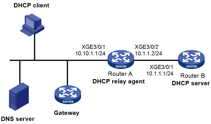
Procedure
1. Specify IP addresses for the interfaces on the DHCP server. (Details not shown.)
2. Configure DHCP:
# Create DHCP user class tt and configure a match rule to match DHCP requests that contain Option 82.
<RouterB> system-view
[RouterB] dhcp class tt
[RouterB-dhcp-class-tt] if-match rule 1 option 82
[RouterB-dhcp-class-tt] quit
# Create DHCP user class ss and configure a match rule to match DHCP requests in which the hardware address is six bytes long and begins with aabb-aabb-aab.
[RouterB] dhcp class ss
[RouterB-dhcp-class-ss] if-match rule 1 hardware-address aabb-aabb-aab0 mask ffff-ffff-fff0
[RouterB-dhcp-class-ss] quit
# Create IP pool aa.
[RouterB] ip pool aa
# Specify the subnet for dynamic allocation.
[RouterB-ip-pool-aa] network 10.10.1.0 mask 255.255.255.0
# Specify the address range for dynamic allocation.
[RouterB-ip-pool-aa] address range 10.10.1.2 10.10.1.100
# Specify the address range for user class tt.
[RouterB-ip-pool-aa] class tt range 10.10.1.2 10.10.1.10
# Specify the address range for user class ss.
[RouterB-ip-pool-aa] class ss range 10.10.1.11 10.10.1.26
# Specify the gateway address and the DNS server address.
[RouterB-ip-pool-aa] gateway-list 10.10.1.254
[RouterB-ip-pool-aa] dns-list 10.10.1.20
[RouterB-ip-pool-aa] quit
# Enable DHCP and configure the DHCP server to handle Option 82.
[RouterB] dhcp enable
[RouterB] dhcp server relay information enable
# Enable the DHCP server on the interface Ten-GigabitEthernet3/0/1.
[RouterB] interface ten-gigabitethernet 3/0/1
[RouterB-Ten-GigabitEthernet3/0/1] dhcp select server
[RouterB-Ten-GigabitEthernet3/0/1] quit
Verifying the configuration
# Verify that clients matching the DHCP user classes can obtain IP addresses in the specified ranges and all other configuration parameters from the DHCP server. (Details not shown.)
# On the DHCP server, display the IP addresses assigned to the clients.
[RouterB] display dhcp server ip-in-use
IP address Client identifier/ Lease expiration Type
Hardware address
10.10.1.2 0031-3865-392e-6262- Jan 14 22:25:03 2015 Auto(C)
3363-2e30-3230-352d-
4745-302f-30
10.10.1.11 aabb-aabb-aab1 Jan 14 22:25:03 2015 Auto(C)
Example: Configuring DHCP user class allowlist
Network configuration
As shown in Figure 13, configure the DHCP user class allowlist to allow the DHCP server to assign IP addresses to clients whose hardware addresses are six bytes long and begin with aabb-aabb.

Procedure
1. Specify IP addresses for the interfaces on the DHCP server. (Details not shown.)
2. Configure DHCP:
# Create DHCP user class ss and configure a match rule to match DHCP requests in which the hardware address is six bytes long and begins with aabb-aabb.
<RouterB> system-view
[RouterB] dhcp class ss
[RouterB-dhcp-class-ss] if-match rule 1 hardware-address aabb-aabb-0000 mask ffff-ffff-0000
[RouterB-dhcp-class-ss] quit
# Create IP pool aa.
[RouterB] ip pool aa
# Specify the subnet for dynamic allocation.
[RouterB-ip-pool-aa] network 10.1.1.0 mask 255.255.255.0
# Enable the DHCP user class allowlist.
[RouterB-ip-pool-aa] verify class
# Add DHCP user class ss to the DHCP user class allowlist.
[RouterB-ip-pool-aa] valid class ss
[RouterB-ip-pool-aa] quit
# Enable DHCP.
[RouterB] dhcp enable
# Enable the DHCP server on Ten-GigabitEthernet 3/0/1.
[RouterB] interface ten-gigabitethernet 3/0/1
[RouterB-Ten-GigabitEthernet3/0/1] dhcp select server
[RouterB-Ten-GigabitEthernet3/0/1] quit
Verifying the configuration
# Verify that clients matching the DHCP user class can obtain IP addresses on subnet 10.1.1.0/24 from the DHCP server. (Details not shown.)
# On the DHCP server, display the IP addresses assigned to the clients.
[RouterB] display dhcp server ip-in-use
IP address Client identifier/ Lease expiration Type
Hardware address
10.1.1.2 aabb-aabb-ab01 Jan 14 22:25:03 2015 Auto(C)
Example: Configuring primary and secondary network segments
Network configuration
As shown in Figure 14, the DHCP server (Router A) assigns IP addresses to DHCP clients in the LAN.
Configure two network segments in the IP pool on the DHCP server: 10.1.1.0/24 as the primary network segment and 10.1.2.0/24 as the secondary network segment. The DHCP server selects an IP address from the secondary network segment when the primary network segment has no assignable addresses.
Router A assigns the following parameters:
· The default gateway 10.1.1.254/24 to clients on network segment 10.1.1.0/24.
· The default gateway 10.1.2.254/24 to clients on network segment 10.1.2.0/24.
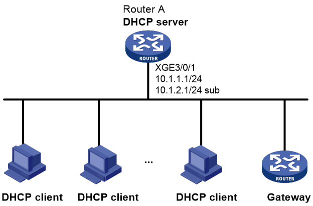
Procedure
# Create IP pool aa.
<RouterA> system-view
[RouterA] ip pool aa
# Specify the primary network segment and the gateway address for dynamic allocation.
[RouterA-ip-pool-aa] network 10.1.1.0 mask 255.255.255.0
[RouterA-ip-pool-aa] gateway-list 10.1.1.254
# Specify the secondary network segment and the gateway address for dynamic allocation.
[RouterA-ip-pool-aa] network 10.1.2.0 mask 255.255.255.0 secondary
[RouterA-ip-pool-aa-secondary] gateway-list 10.1.2.254
[RouterA-ip-pool-aa-secondary] quit
[RouterA-ip-pool-aa] quit
# Enable DHCP.
[RouterA] dhcp enable
# Configure the primary and secondary IP addresses of Ten-GigabitEthernet3/0/1, and enable the DHCP server on Ten-GigabitEthernet 3/0/1.
[RouterA] interface ten-gigabitethernet 3/0/1
[RouterA-Ten-GigabitEthernet3/0/1] ip address 10.1.1.1 24
[RouterA-Ten-GigabitEthernet3/0/1] ip address 10.1.2.1 24 sub
[RouterA-Ten-GigabitEthernet3/0/1] dhcp select server
[RouterA-Ten-GigabitEthernet3/0/1] quit
Verifying the configuration
# Verify that the DHCP server assigns clients IP addresses and gateway address from the secondary network segment when no assignable address is available from the primary network segment. (Details not shown.)
# On the DHCP server, display IP addresses assigned to the clients. The following is part of the command output.
[RouterA] display dhcp server ip-in-use
IP address Client-identifier/ Lease expiration Type
Hardware address
10.1.1.2 0031-3865-392e-6262- Jan 14 22:25:03 2015 Auto(C)
3363-2e30-3230-352d-
4745-302f-30
10.1.2.2 3030-3030-2e30-3030- Jan 14 22:25:03 2015 Auto(C)
662e-3030-3033-2d45-
7568-6572-1e
Example: Customizing DHCP option
Network configuration
As shown in Figure 15, DHCP clients obtain IP addresses and PXE server addresses from the DHCP server (Router A). The subnet for address allocation is 10.1.1.0/24.
Configure the address allocation scheme as follows:
|
Assign PXE addresses |
To clients |
|
2.3.4.5 and 3.3.3.3 |
The hardware address in the request is six bytes long and begins with aabb-aabb. |
|
1.2.3.4 and 2.2.2.2. |
Other clients. |
The DHCP server assigns PXE server addresses to DHCP clients through Option 43, a custom option. The formats of Option 43 and PXE server address sub-option are shown in Figure 5 and Figure 7. For example, the value of Option 43 configured in the IP pool is 80 0B 00 00 02 01 02 03 04 02 02 02 02.
· The number 80 is the value of the sub-option type.
· The number 0B is the value of the sub-option length.
· The numbers 00 00 are the value of the PXE server type.
· The number 02 indicates the number of servers.
· The numbers 01 02 03 04 02 02 02 02 indicate that the PXE server addresses are 1.2.3.4 and 2.2.2.2.

Procedure
1. Specify an IP address for Ten-GigabitEthernet 3/0/1. (Details not shown.)
2. Configure the DHCP server:
# Create DHCP user class ss and configure a match rule to match DHCP requests in which the hardware address is six bytes long and begins with aabb-aabb.
<RouterA> system-view
[RouterA] dhcp class ss
[RouterA-dhcp-class-ss] if-match rule 1 hardware-address aabb-aabb-0000 mask ffff-ffff-0000
[RouterA-dhcp-class-ss] quit
# Create DHCP option group 1 and customize Option 43.
[RouterA] dhcp option-group 1
[RouterA-dhcp-option-group-1] option 43 hex 800B0000020203040503030303
# Create IP pool 0.
[RouterA] ip pool 0
# Specify the subnet for dynamic address allocation.
[RouterA-ip-pool-0] network 10.1.1.0 mask 255.255.255.0
# Customize Option 43.
[RouterA-ip-pool-0] option 43 hex 800B0000020102030402020202
# Associate DHCP user class ss with option group 1.
[RouterA-ip-pool-0] class ss option-group 1
[RouterA-ip-pool-0] quit
# Enable DHCP.
[RouterA] dhcp enable
# Enable the DHCP server on Ten-GigabitEthernet 3/0/1.
[RouterA] interface ten-gigabitethernet 3/0/1
[RouterA-Ten-GigabitEthernet3/0/1] dhcp select server
[RouterA-Ten-GigabitEthernet3/0/1] quit
Verifying the configuration
# Verify that Router B can obtain an IP address on subnet 10.1.1.0/24 and the corresponding PXE server addresses from Router A. (Details not shown.)
# On the DHCP server, display the IP addresses assigned to the clients.
[RouterA] display dhcp server ip-in-use
IP address Client-identifier/ Lease expiration Type
Hardware address
10.1.1.2 aabb-aabb-ab01 Jan 14 22:25:03 2015 Auto(C)
Troubleshooting DHCP server configuration
Failure to obtain a non-conflicting IP address
Symptom
A client's IP address obtained from the DHCP server conflicts with an IP address of another host.
Solution
Another host on the subnet might have the same IP address.
To resolve the problem:
1. Disable the client's network adapter or disconnect the client's network cable. Ping the IP address of the client from another host to check whether there is a host using the same IP address.
2. If a ping response is received, the IP address has been manually configured on a host. Execute the dhcp server forbidden-ip command on the DHCP server to exclude the IP address from dynamic allocation.
3. Enable the network adapter or connect the network cable, release the IP address, and obtain another one on the client. For example, to release the IP address and obtain another one on a Windows XP DHCP client:
a. In Windows environment, execute the cmd command to enter the DOS environment.
b. Enter ipconfig /release to relinquish the IP address.
c. Enter ipconfig /renew to obtain another IP address.
Configuring the DHCP relay agent
About DHCP relay agent
The DHCP relay agent enables clients to get IP addresses and configuration parameters from a DHCP server on another subnet.
Figure 16 shows a typical application of the DHCP relay agent.
Figure 16 DHCP relay agent application
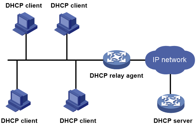
DHCP relay agent operation
The DHCP server and client interact with each other in the same way regardless of whether the relay agent exists. For the interaction details, see "IP address allocation process." The following only describes steps related to the DHCP relay agent:
1. After receiving a DHCPDISCOVER or DHCPREQUEST broadcast message from a DHCP client, the DHCP relay agent processes the message as follows:
a. Fills the giaddr field of the message with its IP address.
b. Unicasts the message to the designated DHCP server.
2. Based on the giaddr field, the DHCP server returns an IP address and other configuration parameters in a response.
3. The relay agent conveys the response to the client.
Figure 17 DHCP relay agent operation

DHCP relay agent support for Option 82
Option 82 records the location information about the DHCP client. It enables the administrator to perform the following tasks:
· Locate the DHCP client for security and accounting purposes.
· Assign IP addresses in a specific range to clients.
For more information about Option 82, see "Relay agent option (Option 82)."
If the DHCP relay agent supports Option 82, it handles DHCP requests by following the strategies described in Table 3.
If a response returned by the DHCP server contains Option 82, the DHCP relay agent removes the Option 82 before forwarding the response to the client.
Table 3 Handling strategies of the DHCP relay agent
|
If a DHCP request has… |
Handling strategy |
The DHCP relay agent… |
|
Option 82 |
Drop |
Drops the message. |
|
Keep |
Forwards the message without changing Option 82. |
|
|
Replace |
Forwards the message after replacing the original Option 82 with the Option 82 padded according to the configured padding format, padding content, and code type. |
|
|
No Option 82 |
N/A |
Forwards the message after adding Option 82 padded according to the configured padding format, padding content, and code type. |
DHCP relay agent support for MCE
An MCE device acting as the DHCP relay agent can forward DHCP packets between a DHCP server and clients on either a public network or a private network. For more information about MCE, see MPLS Configuration Guide.
Restrictions and guidelines: DHCP relay agent configuration
· To ensure successful traffic forwarding, make sure the IP addresses assigned to clients are from the same subnet as the IP address of the relay interface to which they are attached.
· As a best practice, enable DHCP proxy on the device. For more information about enabling DHCP proxy, see "Enabling DHCP proxy on the DHCP relay agent."
· In a Layer 3 IPoE network, enable DHCP proxy on the relay agent and disable the DHCP relay agent from recording relay entries for clients.
· When you enable MAC address check on the relay agent, enable DHCP flood attack protection together.
DHCP relay agent tasks at a glance
To configure a DHCP relay agent, perform the following tasks:
2. Enabling the DHCP relay agent on an interface
4. (Optional.) Configuring the DHCP relay agent security features
5. (Optional.) Configuring advanced functions:
¡ Configuring DHCP server liveness detection
¡ Configuring the DHCP relay agent to release an IP address
¡ Configuring DHCP relay agent support for Option 82
¡ Setting the DSCP value for DHCP packets sent by the DHCP relay agent
¡ Configuring DHCP packet rate limit on a DHCP relay interface
¡ Specifying the DHCP relay agent address for the giaddr field
¡ Specifying the source IP address for relayed DHCP requests
¡ Configuring the DHCP relay agent to always unicast relayed DHCP responses
¡ Configuring forwarding DHCP replies based on Option 82
¡ Setting the maximum number of DHCP-NAK packets
¡ Enabling the IP conflicting user offline feature
¡ Specifying a DHCP request processing method for roaming DHCP clients
¡ Enabling the non-first-hop DHCP relay agent feature
¡ Enabling DHCP-NAK-triggered remote BAS IP pool switchover
Enabling DHCP
Restrictions and guidelines
You must enable DHCP to make other DHCP relay agent settings take effect.
Procedure
1. Enter system view.
system-view
2. Enable DHCP.
dhcp enable
By default, DHCP is disabled.
Enabling the DHCP relay agent on an interface
About this task
With the DHCP relay agent enabled, an interface forwards incoming DHCP requests to a DHCP server.
An IP pool that contains the IP address of the DHCP relay interface must be configured on the DHCP server. Otherwise, the DHCP clients connected to the relay agent cannot obtain correct IP addresses.
Procedure
1. Enter system view.
system-view
2. Enter interface view.
interface interface-type interface-number
3. Enable the DHCP relay agent.
dhcp select relay
By default, when DHCP is enabled, an interface operates in the DHCP server mode.
Specifying DHCP servers
Specifying DHCP servers on a relay agent
About this task
To improve availability, you can specify several DHCP servers on the DHCP relay agent. When the interface receives request messages from clients, the relay agent forwards them to all DHCP servers.
Restrictions and guidelines
The IP address of any specified DHCP server must not reside on the same subnet as the IP address of the relay interface. Otherwise, the clients might fail to obtain IP addresses.
If the desired DHCP server has both primary and secondary IP addresses, you can specify this DHCP server only by its primary IP address.
The DHCP relay agent forwards the packets from clients to the specified DHCP server in the specified virtual network (MPLS L3VPN instance or the public network). If you do not specify an MPLS L3VPN instance or the public network, the DHCP relay agent forwards the packets from a client in the same virtual network as the client.
Procedure
1. Enter system view.
system-view
2. Enter interface view.
interface interface-type interface-number
3. Specify a DHCP server address on the relay agent.
dhcp relay server-address ip-address[ public | vpn-instance vpn-instance-name ]
By default, no DHCP server address is specified on the relay agent.
To specify multiple DHCP server addresses, repeat this step. You can specify a maximum of eight DHCP servers.
Configuring a remote BAS IP pool on a DHCP relay agent
About this task
You can create a remote BAS IP pool and specify DHCP servers in this IP pool. This feature allows DHCP clients of the same type to obtain IP addresses and other configuration parameters from the DHCP servers specified in the matching remote BAS IP pool.
It applies to scenarios where the DHCP relay agent connects to clients of the same access type but classified into different types by their locations. In this case, the relay interface typically has no IP address configured. You can use the gateway command to specify a gateway address and mask for clients matching the same remote BAS IP pool and bind the gateway address to the device's MAC address. Example network is the IPoE network.
Upon receiving a DHCP DISCOVER or REQUEST from a client that matches a remote BAS IP pool, the relay agent processes the packet as follows:
· Fills the giaddr field of the packet with the specified gateway address.
· Forwards the packet to all DHCP servers in the matching IP pool.
The DHCP servers select an IP pool according to the gateway address.
Restrictions and guidelines
If IPoE or PPPoE users are in the network, the remote-server command also configures the device as a DHCP relay agent. You do not need to enable the DHCP relay agent by using the dhcp select relay command.
Procedure
1. Enter system view.
system-view
2. Create a remote BAS IP pool and enter its view.
ip pool pool-name bas remote
3. Specify a gateway IP address and mask for the remote BAS IP pool.
gateway ip-address { mask | mask-len }
By default, no gateway is specified.
4. Specify DHCP servers for the remote BAS IP pool.
remote-server ip-address&<1-8>
By default, no DHCP server is specified for the remote BAS IP pool.
You can specify a maximum of eight DHCP servers for one remote BAS IP pool for high availability.
Specifying the DHCP server selection algorithm
About this task
The DHCP relay agent supports the polling and master-backup DHCP server selection algorithms.
By default, the DHCP relay agent uses the polling algorithm. It forwards DHCP requests to all DHCP servers. The DHCP clients select the DHCP server from which the first received DHCP reply comes.
If the DHCP relay agent uses the master-backup algorithm, it forwards DHCP requests to the master DHCP server first. If the master DHCP server is not available, the relay agent forwards the subsequent DHCP requests to a backup DHCP server. If the backup DHCP server is not available, the relay agent selects the next backup DHCP server, and so on. If no backup DHCP server is available, it repeats the process starting from the master DHCP server.
The master DHCP server is determined in one of the following ways:
· In a common network where multiple DHCP server addresses are specified on the DHCP relay interface, the first specified DHCP server is the master. The other DHCP servers are backup.
· In a network where remote BAS IP pools are configured on the DHCP relay agent, the first specified DHCP server in a remote BAS IP pool is the master. The other DHCP servers in the IP pool are backup. Example networks are IPoE networks.
DHCP server selection supports the following functions:
· DHCP server response timeout time—The DHCP relay agent determines that a DHCP server is not available if it does not receive any response from the server within the DHCP server response timeout time. The DHCP server response timeout time is configurable and the default is 30 seconds.
· DHCP server switchback—If the DHCP relay agent selects a backup DHCP server, it does not switch back to the master DHCP server by default. You can configure the DHCP relay agent to switch back to the master DHCP server after a delay. If the master DHCP server is available, the DHCP relay agent forwards DHCP requests to the master DHCP server. If the master DHCP server is not available, the DHCP relay agent still uses the backup DHCP server.
Specifying the DHCP server selection algorithm in interface view
1. Enter system view.
system-view
2. Enter interface view.
interface interface-type interface-number
3. Specify the DHCP server selection algorithm.
dhcp relay server-address algorithm { master-backup | polling }
By default, the polling algorithm is used. The DHCP relay agent forwards DHCP requests to all DHCP servers.
4. (Optional.) Set the DHCP server response timeout time for DHCP server switchover.
dhcp relay dhcp-server timeout time
By default, the DHCP server response timeout time is 30 seconds.
5. (Optional.) Enable the switchback to the master DHCP server and set the delay time.
dhcp relay master-server switch-delay delay-time
By default, the DHCP relay agent does not switch back to the master DHCP server.
Specifying the DHCP server selection algorithm in remote BAS IP pool view
1. Enter system view.
system-view
2. Enter remote BAS IP pool view.
ip pool pool-name bas remote
3. Specify the DHCP server selection algorithm.
dhcp relay server-address algorithm { master-backup | polling }
By default, the polling algorithm is used. The DHCP relay agent forwards DHCP requests to all DHCP servers.
4. (Optional.) Set the DHCP server response timeout time for DHCP server switchover.
dhcp-server timeout time
By default, the DHCP server response timeout time is 30 seconds.
5. (Optional.) Enable the switchback to the master DHCP server and set the delay time.
master-server switch-delay delay-time
By default, the DHCP relay agent does not switch back to the master DHCP server.
Configuring DHCP server liveness detection
About this task
The feature is applicable to a network where the relay agent selects a DHCP server from a remote BAS IP pool in an IP pool group.
This feature enables the relay agent to detect the liveness of the DHCP servers. Upon relaying the first DHCP request to a DHCP server, the DHCP relay agent starts the timeout timer and request counter. If a reply is received within the timeout time, the relay agent resets packet counter and disables the timeout timer. The relay agent starts the timer and counter again if it relays a new request. A communication failure occurs if the relay agent does not receive a reply.
The relay agent uses the following principles to mark the DHCP server as down ("dead") or has no assignable IP addresses:
· At the end of every timeout period, the agent checks the total number of consecutive communication failures.
¡ If the failure count exceeds the dead-count-value value, the DHCP server is marked as dead.
¡ If the failure count does not exceed the dead-count-value value, the relay agent continues counting the number of requests. The DHCP server is marked as dead if the dead-count-value value is reached at next check.
· The total number of consecutively received DHCP-NAK for the relayed lease renewal packets reaches the nak-count value.
When a DHCP server is marked as dead, the relay agent starts the dead time for the server. Within the dead period, the relay agent does not relay any packets to this DHCP server. After the dead period expires, the relay agent determines that the DHCP server becomes alive, and starts forwarding packets to this server.
If all DHCP servers are marked as dead, the DHCP relay agent treats all DHCP servers as alive if it receives a new DHCP request.
Restrictions and guidelines
If the DHCP server selection algorithm is polling, the longest timeout value among all DHCP servers is used as the check timer for all DHCP servers.
The liveness detection settings specific to a DHCP server have a higher priority than the shared settings. If no DHCP server-specific settings are configured, the shared ones apply.
Procedure
1. Enter system view.
system-view
2. Configure DHCP server liveness detection.
dhcp server [ ip-address [ vpn-instance vpn-instance-name ] ] { dead-count dead-count-value | dead-time dead-time | nak-count nak-count-value | timeout timeout } *
By default, the relay agent marks the DHCP server as dead if the DHCP relay agent does not receive a reply from a DHCP server within 25 seconds.
Configuring the DHCP relay agent security features
Enabling the DHCP relay agent to record relay entries
About this task
Perform this task to enable the DHCP relay agent to automatically record clients' IP-to-MAC bindings (relay entries) after they obtain IP addresses through DHCP.
Some security features use the relay entries to check incoming packets and block packets that do not match any entry. In this way, illegal hosts are not able to access external networks through the relay agent. Examples of the security features are ARP address check, authorized ARP, and IP source guard.
Restrictions and guidelines
The following information applies to WAN access users (for example, IPoE or PPPoE):
· The relay agent does not record client information for WAN access users if it has an authorized IP pool.
· The relay agent always records client information for WAN access users if it does not have an authorized IP pool. You cannot disable the relay agent from doing so.
Procedure
1. Enter system view.
system-view
2. Enable the relay agent to record relay entries.
dhcp relay client-information record
By default, the relay agent does not record relay entries.
Enabling periodic refresh of dynamic relay entries
About this task
A DHCP client unicasts a DHCP-RELEASE message to the DHCP server to release its IP address. The DHCP relay agent conveys the message to the DHCP server and does not remove the IP-to-MAC entry of the client.
With this feature, the DHCP relay agent uses the following information to periodically send a DHCPREQUEST message to the DHCP server:
· The IP address of a relay entry.
· The MAC address of the DHCP relay interface.
The relay agent maintains the relay entries depending on what it receives from the DHCP server:
· If the server returns a DHCP-ACK message or does not return any message within an interval, the DHCP relay agent removes the relay entry. In addition, upon receiving the DHCP-ACK message, the relay agent sends a DHCP-RELEASE message to release the IP address.
· If the server returns a DHCP-NAK message, the relay agent keeps the relay entry.
Restrictions and guidelines
This feature does not take effect on WAN access users (for example, IPoE and PPPoE). If the relay agent does not have an authorized IP pool, the relay agent removes the relay entry for a WAN access user after the lease for that user expires.
Procedure
1. Enter system view.
system-view
2. Enable periodic refresh of dynamic relay entries.
dhcp relay client-information refresh enable
By default, periodic refresh of dynamic relay entries is enabled.
3. (Optional.) Set the refresh interval.
dhcp relay client-information refresh { auto | interval interval }
By default, the refresh interval is auto, which is calculated based on the number of total relay entries.
Enabling lease release notification
About this task
The lease release notification feature enables the DHCP relay agent to send a Release message to the DHCP server after it deletes a relay entry. After the DHCP server receives the message, it reclaims the IP address and marks the lease as expired.
If you do not enable this feature, the DHCP relay agent will not send a Release message after it deletes a relay entry. This might cause a waste of IP addresses. To delete relay entries from the relay agent, you can use the reset dhcp relay client-information command.
Restrictions and guidelines
This command does not take effect on the users that do not come online through access devices. The DHCP relay agent does not send Release messages to the DHCP server after it deletes the relay entries for such users.
This command does not take effect on PPPoE users after you use the cut access-user command to forcibly log out users. The DHCP relay agent will always send Release messages to the DHCP server. For more information about the cut access-user command, see UCM commands in BRAS Services Command Reference.
Procedure
1. Enter system view.
system-view
2. Enter interface view.
interface interface-type interface-number
3. Enable lease release notification.
dhcp relay release-agent
By default, lease release notification is enabled.
Configuring DHCP flood attack protection
About this task
The DHCP flood attack protection enables the DHCP relay agent to detect DHCP flood attacks according to the DHCP packet rate threshold on a per-MAC basis.
When the DHCP relay agent receives a DHCP packet from a client (MAC address), it creates a DHCP flood attack protection entry in check state. If the number of DHCP packets from the same MAC address reaches the upper limit in the detection duration, the relay agent determines that the client is launching a DHCP flood attack. The DHCP flood attack protection entry changes to the restrain state, and the DHCP relay agent discards the DHCP packets from that client. When the aging time of the entry is reached, the DHCP relay agent examines the drop rate of DHCP packets sent from the MAC address.
· If the drop rate is lower than the DHCP flood attack threshold, the DHCP relay agent deletes the entry. If later a DHCP packet from that MAC address arrives, the DHCP relay agent will create a new flood attack protection entry and count the number of incoming DHCP packets for that client again.
· If the packet drop rate is equal to or higher than the DHCP flood attack threshold, the DHCP relay agent resets the aging time for the entry.
DHCP flood attack protection takes effect on all interfaces if it is enabled globally. To enable DHCP flood attack protection on only some of the interfaces, disable the feature globally and enable it on the desired interfaces.
Procedure
1. Enter system view.
system-view
2. (Optional) Set the DHCP packet rate threshold for triggering DHCP flood attack protection.
dhcp flood-protection threshold packet-number milliseconds
By default, the device allows a maximum of 10 DHCP packets per 5000 milliseconds from each DHCP client.
3. (Optional) Set the aging time of DHCP flood attack protection entries.
dhcp flood-protection aging-time time
The default setting is 300 seconds.
4. Enable DHCP flood attack protection globally.
dhcp flood-protection global enable
By default, DHCP flood attack protection is disabled globally.
5. Enable DHCP flood attack protection only on one interface.
a. Disable DHCP flood attack protection globally.
undo dhcp flood-protection global enable
By default, DHCP flood attack protection is disabled globally.
b. Enter interface view.
interface interface-type interface-number
c. Enable DHCP flood attack protection on the interface.
dhcp flood-protection enable
By default, DHCP flood attack protection is disabled on interfaces.
Enabling DHCP starvation attack protection
About this task
A DHCP starvation attack occurs when an attacker constantly sends forged DHCP requests using different MAC addresses in the chaddr field to a DHCP server. This exhausts the IP address resources of the DHCP server so legitimate DHCP clients cannot obtain IP addresses. The DHCP server might also fail to work because of exhaustion of system resources. The following methods are available to relieve or prevent such attacks.
· To relieve a DHCP starvation attack that uses DHCP packets encapsulated with different source MAC addresses, you can use one of the following methods:
¡ Limit the number of ARP entries that a Layer 3 interface can learn.
¡ Set the MAC learning limit for a Layer 2 port, and disable unknown frame forwarding when the MAC learning limit is reached.
· To prevent a DHCP starvation attack that uses DHCP requests encapsulated with the same source MAC address, you can enable MAC address check on the DHCP relay agent. The DHCP relay agent compares the chaddr field of a received DHCP request with the source MAC address in the frame header. If they are the same, the DHCP relay agent forwards the request to the DHCP server. If not, the relay agent discards the request.
Enable MAC address check only on the DHCP relay agent directly connected to the DHCP clients. A DHCP relay agent changes the source MAC address of DHCP packets before sending them.
A MAC address check entry has an aging time. When the aging time expires, both of the following occur:
· The entry ages out.
· The DHCP relay agent rechecks the validity of DHCP requests sent from the MAC address in the entry.
Restrictions and guidelines
This feature only checks whether the chaddr field of a received DHCP-DISCOVER message is the same as the source MAC address in the frame header.
Procedure
1. Enter system view.
system-view
2. Set the aging time for MAC address check entries.
dhcp relay check mac-address aging-time time
The default aging time is 30 seconds.
This command takes effect only after you execute the dhcp relay check mac-address command.
3. Enter the interface view.
interface interface-type interface-number
4. Enable MAC address check.
dhcp relay check mac-address
By default, MAC address check is disabled.
Enabling DHCP proxy on the DHCP relay agent
About this task
The DHCP proxy feature isolates DHCP servers from DHCP clients and protects DHCP servers against attacks.
Upon receiving a response from the server, the DHCP server proxy performs the following task:
1. Modifies the server's IP address as the IP address of the relay's output interface or the IP address in the giaddr field.
2. Sends the response to the DHCP client.
On receipt of the response, the DHCP client will take the DHCP relay agent as the DHCP server.
Procedure
1. Enter system view.
system-view
2. Enter interface view.
interface interface-type interface-number
3. Enable DHCP proxy on the interface.
dhcp-proxy enable
By default, the interface operates in DHCP server mode after DHCP is enabled.
Enabling client offline detection on the DHCP relay agent
About this task
The client offline detection on the DHCP relay agent detects the user online status based on the ARP entry aging. When an ARP entry ages out, the DHCP client offline detection feature deletes the relay entry for the IP address and sends a RELEASE message to the DHCP server.
Restrictions and guidelines
The feature does not function if an ARP entry is manually deleted.
Procedure
1. Enter system view.
system-view
2. Enable the relay agent to record relay entries.
dhcp relay client-information record
By default, the relay agent does not record relay entries.
Without relay entries, client offline detection cannot function correctly.
3. Enter interface view.
interface interface-type interface-number
4. Enable the DHCP relay agent.
dhcp select relay
By default, when DHCP is enabled, an interface operates in the DHCP server mode.
5. Enable client offline detection.
dhcp client-detect
By default, client offline detection is disabled on the DHCP relay agent.
Configuring interface-based DHCP attack suppression
About this task
DHCP attack suppression protects an interface from DHCP attacks by limiting the rate of incoming DHCP packets after the specified threshold is crossed.
When an interface enabled with this feature receives a DHCP packet, the DHCP relay agent creates a DHCP attack suppression entry in check state for the interface. If the incoming DHCP packet rate on the interface reaches the threshold, a DHCP attack occurs on the interface. The suppression entry changes to the restrain state. To protect the CPU against DHCP packets, the device limits the incoming DHCP packet rate on the interface before the aging time of the suppression entry is reached.
When the aging time of the DHCP attack suppression entry on an interface is reached, the device examines the incoming packet rate on the interface.
· If the incoming packet rate is below the suppression threshold, the device deletes the entry. When a new DHCP packet arrives on that interface, the DHCP server creates a new attack suppression entry and count the number of incoming DHCP packets on that interface again.
· If the incoming packet rate is above the suppression threshold, the device resets the aging timer.
Restrictions and guidelines
You can enable DHCP attack suppression globally or on a per-interface basis.
· DHCP attack suppression takes effect on an interface as long as it is enabled globally or on the interface.
· To suppress DHCP attacks only on some of the interfaces, you must disable DHCP attack suppression globally, and then enable the feature on the target interfaces.
Procedure
1. Enter system view.
system-view
2. (Optional.) Set the DHCP packet rate threshold for triggering interface-based DHCP attack suppression.
dhcp interface-rate-suppression threshold packet-number milliseconds
By default, the DHCP relay agent can receive a maximum of 3000 DHCP packets per 5000 milliseconds on an interface.
3. (Optional.) Set the aging time of interface-based DHCP attack suppression entries.
dhcp interface-rate-suppression aging-time time
The default setting is 300 seconds.
4. Enable DHCP attack suppression.
¡ To enable DHCP attack suppression on all interfaces:
dhcp interface-rate-suppression global enable
By default, global DHCP attack suppression is disabled.
¡ To enable DHCP attack suppression only on some of the interfaces:
i Disable global DHCP attack suppresion if it has been enabled.
undo dhcp interface-rate-suppression global enable
ii Enter interface view.
interface interface-type interface-number
iii Enable DHCP attack suppression on the interface.
dhcp interface-rate-suppression enable
By default, DHCP attack suppression is disabled on interfaces.
Configuring the DHCP relay agent to release an IP address
About this task
Configure the relay agent to release the IP address for a relay entry. The relay agent sends a DHCP-RELEASE message to the server and meanwhile deletes the relay entry. Upon receiving the DHCP-RELEASE message, the DHCP server releases the IP address.
This command can release only the IP addresses in the recorded relay entries.
Procedure
1. Enter system view.
system-view
2. Configure the DHCP relay agent to release an IP address.
dhcp relay release ip ip-address [ vpn-instance vpn-instance-name ]
Configuring DHCP relay agent support for Option 82
To support Option 82, you must perform related configuration on both the DHCP server and relay agent. For DHCP server Option 82 configuration, see "Enabling handling of Option 82."
Procedure
1. Enter system view.
system-view
2. Enter interface view.
interface interface-type interface-number
3. Enable the relay agent to handle Option 82.
dhcp relay information enable
By default, handling of Option 82 is disabled.
4. (Optional.) Configure the strategy for handling DHCP requests that contain Option 82.
dhcp relay information strategy { drop | keep | replace }
By default, the handling strategy is replace.
If the handling strategy is replace, configure a padding mode and a padding format for Option 82. If the handling strategy is keep or drop, you do not need to configure a padding mode or padding format for Option 82.
5. (Optional.) Configure the padding mode and padding format for the Circuit ID sub-option.
dhcp relay information circuit-id { bas [ sub-interface-vlan ] [ with-vxlan ] | string circuit-id | { normal | verbose [ node-identifier { mac | sysname | user-defined node-identifier } ] [ interface [ vlan-in-vlan ] ] } [ sub-interface-vlan ] [ format { ascii | hex } ] }
By default, the padding mode for Circuit ID sub-option is normal, and the padding format is hex.
The device name (sysname) must not include spaces if it is configured as the padding content for sub-option 1. Otherwise, the DHCP relay agent will fail to add or replace Option 82.
6. (Optional.) Configure the padding mode and padding format for the Remote ID sub-option.
dhcp relay information remote-id { normal [ format { ascii | hex } ] | string remote-id | sysname }
By default, the padding mode for the Remote ID sub-option is normal, and the padding format is hex.
Setting the DSCP value for DHCP packets sent by the DHCP relay agent
About this task
The DSCP value of a packet specifies the priority level of the packet and affects the transmission priority of the packet.
Procedure
1. Enter system view.
system-view
2. Set the DSCP value for DHCP packets sent by the DHCP relay agent.
dhcp dscp dscp-value
By default, the DSCP value in DHCP packets sent by the DHCP relay agent is 56.
Configuring DHCP packet rate limit on a DHCP relay interface
About this task
This feature enables the DHCP relay interface to discard DHCP packets that exceed the maximum rate.
Procedure
1. Enter system view.
system-view
2. Enter interface view.
interface interface-type interface-number
3. Enable DHCP packet rate limit on the interface and set the limit value.
dhcp rate-limit rate
By default, DHCP packet rate limit is disabled on an interface.
Specifying the DHCP relay agent address for the giaddr field
Manually specifying the DHCP relay agent address for the giaddr field
About this task
This task allows you to specify the IP addresses to be encapsulated to the giaddr field of the DHCP requests. If you do not specify any DHCP relay agent address, the primary IP address of the DHCP relay interface is encapsulated to the giaddr field of DHCP requests.
Procedure
1. Enter system view.
system-view
2. Enter interface view.
interface interface-type interface-number
3. Specify the DHCP relay agent address to be encapsulated in relayed DHCP requests.
dhcp relay gateway ip-address
By default, the primary IP address of the DHCP relay interface is encapsulated in the relayed DHCP requests.
Configuring smart relay to specify the DHCP relay agent address for the giaddr field
About this task
By default, the relay agent only encapsulates the primary IP address to the giaddr field of all requests before relaying them to the DHCP server. The DHCP server then selects an IP address on the same subnet as the address in the giaddr filed. If no assignable addresses on the subnet are available, the DHCP server does not assign any IP address. The DHCP smart relay feature is introduced to allow the DHCP relay agent to encapsulate secondary IP addresses when the DHCP server does not send back a DHCP-OFFER message.
The relay agent initially encapsulates its primary IP address to the giaddr field before forwarding a request to the DHCP server. If no DHCP-OFFER is received, the relay agent allows the client to send a maximum of two requests to the DHCP server by using the primary IP address. If no DHCP-OFFER is returned after two retries, the relay agent switches to a secondary IP address. If the DHCP server still does not respond, the next secondary IP address is used. After the secondary IP addresses are all tried and the DHCP server does not respond, the relay agent repeats the process by starting from the primary IP address.
Procedure
1. Enter system view.
system-view
2. Enable the DHCP smart relay feature.
dhcp smart-relay enable
By default, the DHCP smart relay feature is disabled.
Specifying the source IP address for relayed DHCP requests
About specifying the source IP address for relayed DHCP requests
By default, the source IP address for relayed DHCP requests depends on the locations of the DHCP server and the server-facing interface on the relay agent:
· If the locations are the same, the relay agent uses the IP address of the output interface for relayed requests as the source IP address. For example, the source IP address is the IP address of Interface B in Figure 18.
Figure 18 The DHCP server and the server-facing interface are in the same VPN

· If the locations are different, the relay agent uses the lowest IP address that is in the same VPN instance as the DHCP server as the source address.
For example, the source IP address is the IP address of Interface C in Figure 19. If Interface C has multiple IP addresses that are in the same VPN instance as the DHCP server, the relay agent selects the lowest IP address as the source address.
Figure 19 The DHCP server and the server-facing interface are in different VPNs

The relay agent determines the location of that DHCP server as follows:
|
|
NOTE: In this task, the location of a DHCP server depends on the configuration of the public or vpn-instance keyword in the dhcp relay server-address command. For DHCP requests to reach a DHCP server, the relay agent must forward them to the location of that DHCP server. |
· When you specify the public keyword in the dhcp relay server-address command, the DHCP server location is the public network.
· When you specify the vpn-instance keyword in the dhcp relay server-address command, the DHCP server location is the specified VPN instance.
· When you use the dhcp relay server-address command without specifying the public or vpn-instance keyword, the DHCP server location depends on the location of the DHCP client. The DHCP client always runs on the same network (VPN instance or public network).
This task is required if multiple relay interfaces share the same IP address or if a relay interface does not have routes to DHCP servers. You can perform this task to specify an IP address or the IP address of another interface on the DHCP relay agent as the source IP address for relayed DHCP requests.
For common networks, you can perform this task on the DHCP relay interface. If you specify the ip-address argument, the relay agent changes not only the source IP address but also the giaddr field of a DHCP request. The DHCP server assigns the client an IP address on the same subnet as the specified IP address in the giaddr field. As a result, the client might not be on the same subnet as the DHCP relay interface (the gateway). To avoid this problem, you must configure Option 82 on the relay interface before specifying the ip-address argument. This configuration enables the DHCP relay agent to insert the primary IP address of the relay interface in Option 82. Based on this option, the DHCP server assigns an IP address on the same subnet as the IP address of the relay interface. The DHCP relay agent looks up the MAC address table for the output interface to forward the DHCP reply packets.
For some networks such as the IPoE networks, you must configure a remote BAS IP pool and specify the source IP address for DHCP requests in remote BAS IP pool view.
Specifying the source IP address for relayed DHCP requests (interface view)
1. Enter system view.
system-view
2. Enter interface view.
interface interface-type interface-number
3. Specify the source IP address for DHCP requests.
dhcp relay source-address { ip-address [ option code [ option-text ] ] | gateway | relay-interface }
By default, the relay agent chooses the default source IP address for relayed requests depending on whether its server-side interface and the DHCP server belong to the same VPN instance:
¡ If they belong to the same VPN instance, the relay agent uses the IP address of the output interface for relayed requests as the default source IP address.
¡ If they belong to different VPN instances, the relay agent uses the lowest IP address that is in the same VPN instance as the DHCP server as the default source address.
|
Keyword |
Description |
|
ip-address code [ option-text ] |
If a DHCP request carries the specified option, the relay agent changes the source IP address and the giaddr field of the DHCP request to the specified IP address. |
|
gateway |
The relay agent uses the IP address in the giaddr field as the source IP address. If the giaddr field is empty, the relay agent follows the default rule to specify the source IP address for DHCP requests. |
|
relay-interface |
The relay agent uses the primary IP address of the relay interface as the source IP address. If this interface does not have an IP address, the relay agent follows the default rule to specify the source IP address for DHCP requests. |
Specifying the source IP address for relayed DHCP requests (remote BAS IP pool view)
1. Enter system view.
system-view
2. Create a remote BAS IP pool and enter its view.
ip pool pool-name bas remote
3. Specify the source IP address for DHCP requests.
dhcp-server source-address { ip-address | gateway | interface interface-type interface-number }
By default, the relay agent chooses the default source IP address for relayed requests depending on whether its server-side interface and the DHCP server belong to the same VPN instance:
¡ If they belong to the same VPN instance, the relay agent uses the IP address of the output interface for relayed requests as the default source IP address.
¡ If they belong to different VPN instances, the relay agent uses the lowest IP address that is in the same VPN instance as the DHCP server as the default source address.
|
Keyword |
Description |
|
ip-address |
The relay agent uses the specified IP address as the source IP address for relay DHCP requests. |
|
gateway |
The relay agent uses the IP address in the giaddr field as the source IP address. If the giaddr field is empty, the relay agent follows the default rule to specify the source IP address for DHCP requests. |
|
interface interface-type interface-number |
The relay agent uses the IP address of the specified interface as the source IP address. If this interface does not have an IP address, the relay agent follows the default rule to specify the source IP address for DHCP requests. |
Configuring the DHCP relay agent to always unicast relayed DHCP responses
About this task
This feature enables the DHCP relay agent to ignore the broadcast flag and always unicast relayed responses. This feature is useful in some LANs, such as a WLAN network, where broadcast communication is not recommended.
Procedure
1. Enter system view.
system-view
2. Enable the DHCP relay agent to always unicast relayed DHCP responses.
dhcp relay always-unicast
By default, the DHCP relay agent reads the broadcast flag to decide whether to broadcast or unicast a response.
Configuring forwarding DHCP replies based on Option 82
About this task
Configure this feature if the DHCP relay agent is required to forward DHCP replies to DHCP clients based on Option 82.
Procedure
1. Enter system view.
system-view
2. Enter interface view.
interface interface-type interface-number
3. Enable the relay agent to handle Option 82.
dhcp relay information enable
By default, handling of Option 82 is disabled.
4. Configure the padding mode and padding format for the Circuit ID sub-option.
dhcp relay information circuit-id { bas [ sub-interface-vlan ] [ with-vxlan ] | string circuit-id | { normal | verbose [ node-identifier { mac | sysname | user-defined node-identifier } ] [ interface [ vlan-in-vlan ] ] } [ sub-interface-vlan ] [ format { ascii | hex } ] }
By default, the padding mode for the Circuit ID sub-option is normal, and the padding format is hex.
The device name (set by using the sysname command) must not include spaces if it is configured as the padding content for sub-option 1. Otherwise, the DHCP relay agent will fail to add or replace Option 82.
You must set the padding mode to bas, normal, or verbose, and specify the sub-interface-vlan keyword for this command.
5. Configure the DHCP relay agent to forward DHCP replies based on Option 82.
dhcp relay forward reply by-option82
By default, the DHCP relay agent does not forward DHCP replies based on Option 82.
Setting the maximum number of DHCP-NAK packets
About this task
This value limits the maximum number of DHCP-NAK packets that the DHCP relay can receive from one DHCP server. Use this feature only in a network when the master-backup server selection is configured in the remote BAS IP pool. In such a network, you can use the gateway-list command to specify gateway addresses for users that match the remote BAS IP pool. When the relay agent receives a lease renew request from a DHCP client, the relay agent forwards the request to the currently selected DHCP server. When the number of DHCP-NAK packets from the DHCP server reaches the upper limit, the DHCP relay agent performs one of the following operations, depending on the configuration:
· If the gateway-only keyword is not configured, the DHCP relay agent forwards the request to the next DHCP server.
· If the gateway-only keyword is configured and smart relay is enabled, the relay agent uses the next gateway address configured in the gateway-list command to fill the giaddr field.
· If the gateway-only keyword is not configured, and smart relay is enabled, the relay agent performs the following operations:
a. Uses the next gateway address in the gateway-list command to fill the giaddr field.
b. Forwards the request to the next DHCP server.
Procedure
1. Enter system view.
system-view
2. Enter remote BAS IP pool view.
ip pool pool-name bas remote
3. Set the maximum of DHCP-NAK packets that the DHCP relay agent can receive from one DHCP server.
dhcp-server nak-count nak-count-value [ gateway-only ]
By default, the DHCP relay agent can receive a maximum of 10 DHCP-NAK packets from one DHCP server.
Enabling the IP conflicting user offline feature
About this task
The following IP address conflicts might occur in a network:
· The IP address assigned by the authentication and authorization module to a new user is the same as the IP address of an online DHCP client.
· The IP address assigned by the DHCP server to a new DHCP client is the same as the IP address in the DHCP relay entry of an online DHCP client.
If these conflicts occur, by default, the conflicting online DHCP clients still stay online, and new users cannot come online.
This feature enables the server to release the conflicting IP address when an IP conflict occurs, and informs the access module that the address is not available. Both the online user and requesting users are offline. It ensures that a new user can obtain an IP address next time the user request the IP address through DHCP.
With this feature enabled on the DHCP relay agent, the relay agent processes the conflicts as follows:
· If the IP address assigned to a new user by the authentication and authorization module conflicts with the DHCP relay entry of an online client, the relay agent performs the following operations:
a. Sends a DHCP-RELEASE packet to the DHCP server to release the conflicting IP address.
b. Informs the access module of the new user that this IP address is not available.
· If the IP address in the DHCP reply for a new user conflicts with the DHCP relay entry of an online client, the relay agent performs the following operations:
a. Sends a DHCP-RELEASE packet to the server to release the conflicting IP address.
b. Drops the DHCP reply.
Restrictions and guidelines
This feature takes effect on the DHCP relay agent only after you enable the recording of relay entries on it.
Enable this feature on the DHCP relay device if one DHCP relay agent-enabled interface connects to an IPoE network and the other DHCP relay agent-enabled interface connects to a common network. This is because the following commands are required on the device for IPoE:
· dhcp relay client-information record
· undo dhcp relay client-information refresh enable
In this case, the common network-facing interface records DHCP relay entries but does not update them. An IP address conflict occurs if the IP address assigned to a new client already exists in a recorded DHCP relay entry. With this feature enabled, DHCP clients can obtain IP addresses correctly.
Procedure
1. Enter system view.
system-view
2. Enable the IP conflicting user offline feature.
dhcp conflict-ip-address offline
By default, the IP conflicting user offline feature is disabled. When the IP address assigned to a new DHCP client conflicts with the IP address of an online DHCP client, the online DHCP client still stays online.
Specifying a DHCP request processing method for roaming DHCP clients
About this task
When a DHCP client roams in a network, the client sends an offline request to the DHCP relay agent before requesting a new address. If the DHCP relay agent does not receive the offline request, it will discard the DHCP client's new address request because it determines that the request is an attack packet.
This feature allows the DHCP relay agent to process address requests as follows upon receiving them from roaming DHCP clients:
· The fast-renew method enables the relay agent to inform the DHCP server to release existing address leases of roaming clients and forward the requests to the DHCP server.
· The roam method enables the relay agent to forward the address requests to the DHCP server. The clients can use the original IP addresses to access the network without another authentication.
Restrictions and guidelines
This feature is applicable to only IPoE networks.
The roam keyword in the dhcp session-mismatch action { fast-renew | roam } command can take effect only after you enable roaming for IPoE individual users by using the ip subscriber roaming enable command.
For more information about IPoE roaming, see IPoE configuration in BRAS Services Configuration Guide.
Procedure
1. Enter system view.
system-view
2. Enter interface view.
interface interface-type interface-number
3. Specify a method for the DHCP relay agent to process address requests of roaming clients.
dhcp session-mismatch action { fast-renew | roam }
By default, the DHCP relay agent discards DHCP address requests sent from roaming DHCP clients.
Enabling the non-first-hop DHCP relay agent feature
About this task
Multiple DHCP relay agents might exist between a DHCP client and the DHCP server. By default, only the first DHCP relay agent that the DHCP request passes through processes the request and the subsequent DHCP relay agents only forward the request. If access authentication is enabled on a non-first DHCP relay agent, execute this command on this relay agent for the relay agent to deliver the packet to the authentication module for authentication and authorization.
Enable this feature only on the non-first-hop DHCP relay agent where access authentication is enabled.
Restrictions and guidelines
To have this feature function correctly:
· Enable the DHCP relay agent on the downstream interface of the non-first-hop DHCP relay device towards clients.
· Enable the non-first-hop DHCP relay agent on both the upstream and downstream interfaces of the device.
To ensure correct forwarding of DHCP messages, do not use either of the following commands to change the giaddr field in DHCP messages:
· dhcp relay gateway
· dhcp relay source-address
Procedure
1. Enter system view.
system-view
2. Enter interface view.
interface interface-type interface-number
3. Enable the non-first-hop DHCP relay agent feature.
dhcp relay non-first-hop enable
By default, the non-first-hop DHCP relay agent feature is disabled.
Enabling DHCP-NAK-triggered remote BAS IP pool switchover
About this task
Some DHCP servers respond with DHCP-NAK messages to the DHCP-DISCOVER messages from clients when they have no assignable IP addresses. By default, the relay agent continues to forward DHCP-DISCOVER messages to the server, regardless of how many DHCP-NAK messages it has received from that server. If the server is in one remote BAS IP pool in an IP pool group, the server does not move to the next remote BAS IP pool, if any.
For clients to obtain an IP address as soon as possible from one of the remote BAS IP pools in an IP pool group, set the DHCP-NAK threshold and statistic period to trigger remote BAS IP pool switchover
Procedure
1. Enter system view.
system-view
2. Enter IP pool group view.
ip pool-group pool-group-name
3. Set the DHCP-NAK threshold and statistic period for DHCP-NAK-triggered remote BAS IP pool switchover.
discover-nak-count nak-count seconds
By default, the relay agent forwards DHCP-DISCOVER messages to the server in the current remote BAS IP pool, regardless of how many DHCP-NAK messages it has received from that server.
Display and maintenance commands for DHCP relay agent
Execute display commands in any view and reset commands in user view.
|
Task |
Command |
|
Display information about DHCP flood attack entries. |
display dhcp flood-protection slot slot-number [ mac-address mac-address [ interface interface-type interface-number ] | state { check | restrain } [ verbose ] | statistics | verbose ] |
|
Display information about interface-based DHCP attack suppression entries. |
display dhcp interface-rate-suppression slot slot-number [ interface interface-type interface-number | state { check | restrain [ verbose ] } | statistics | verbose ] |
|
Display packet statistics for the DHCP packet rate-limiting feature. |
display dhcp rate-limit slot slot-number |
|
Display information about DHCP servers on an interface. |
display dhcp relay server-address [ interface interface-type interface-number ] |
|
Display Option 82 configuration information on the DHCP relay agent. |
display dhcp relay information [ interface interface-type interface-number ] |
|
Display relay entries on the DHCP relay agent. |
display dhcp relay client-information [ interface interface-type interface-number | ip ip-address [ vpn-instance vpn-instance-name ] ] |
|
Display the DHCP server configuration and status in the remote BAS IP pool on the DHCP relay agent. |
display dhcp relay remote-server-info [ vpn-instance vpn-name ] [ slot slot-number ] |
|
Display packet statistics on the DHCP relay agent. |
display dhcp relay packet statistics [ interface interface-type interface-number ] |
|
Delete DHCP flood attack protection entries. |
reset dhcp flood-protection slot slot-number [ mac-address mac-address [ interface interface-type interface-number ] ] [ packet-statistics ] |
|
Delete interface-based DHCP attack suppression entries. |
reset dhcp interface-rate-suppression slot slot-number [ interface interface-type interface-number ] [ packet-statistics ] |
|
Clear the packet statistics for the DHCP packet rate-limiting feature. |
reset dhcp rate-limit slot slot-number |
|
Clear relay entries on the DHCP relay agent. |
reset dhcp relay client-information [ interface interface-type interface-number | ip ip-address [ vpn-instance vpn-instance-name ] ] |
|
Clear packet statistics on the DHCP relay agent. |
reset dhcp relay packet statistics [ interface interface-type interface-number ] |
DHCP relay agent configuration examples
Example: Configuring basic DHCP relay agent
Network configuration
As shown in Figure 20, configure the DHCP relay agent on Router A. The DHCP relay agent enables DHCP clients to obtain IP addresses and other configuration parameters from the DHCP server on another subnet.
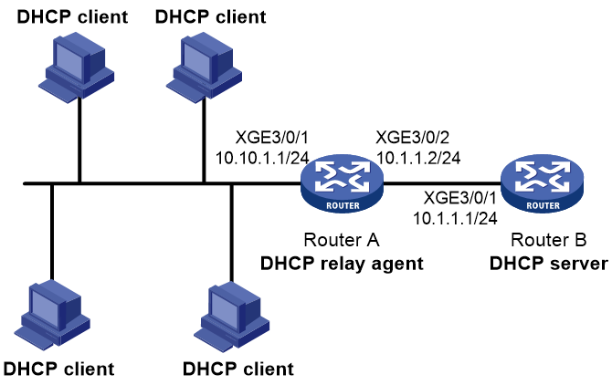
Prerequisites
Because the DHCP relay agent and server are on different subnets, configure static or dynamic routing to make them reachable to each other.
Configure the DHCP server to guarantee the client-server communication through the DHCP relay agent. For more information, see "DHCP server configuration examples."
Procedure
# Specify IP addresses for the interfaces. (Details not shown.)
# Enable DHCP.
<RouterA> system-view
[RouterA] dhcp enable
# Enable the DHCP relay agent on Ten-GigabitEthernet 3/0/1.
[RouterA] interface ten-gigabitethernet 3/0/1
[RouterA-Ten-GigabitEthernet3/0/1] dhcp select relay
# Specify the IP address of the DHCP server on the relay agent.
[RouterA-Ten-GigabitEthernet3/0/1] dhcp relay server-address 10.1.1.1
Verifying the configuration
# Verify that DHCP clients can obtain IP addresses and all other network parameters from the DHCP server through the DHCP relay agent. (Details not shown.)
# Display the statistics of DHCP packets forwarded by the DHCP relay agent.
[RouterA] display dhcp relay packet statistics
# Display relay entries if you have enabled relay entry recording on the DHCP relay agent.
[RouterA] display dhcp relay client-information
Example: Configuring Option 82
Network configuration
As shown in Figure 20, the DHCP relay agent (Router A) replaces Option 82 in DHCP requests before forwarding them to the DHCP server (Router B).
· The Circuit ID sub-option is company001.
· The Remote ID sub-option is device001.
Prerequisites
To use Option 82, enable the DHCP server to handle Option 82.
Procedure
# Specify IP addresses for the interfaces. (Details not shown.)
# Enable DHCP.
<RouterA> system-view
[RouterA] dhcp enable
# Enable the DHCP relay agent on Ten-GigabitEthernet 3/0/1.
[RouterA] interface ten-gigabitethernet 3/0/1
[RouterA-Ten-GigabitEthernet3/0/1] dhcp select relay
# Specify the IP address of the DHCP server on the relay agent.
[RouterA-Ten-GigabitEthernet3/0/1] dhcp relay server-address 10.1.1.1
# Enable the DHCP relay agent to handle Option 82, and perform Option 82 related configuration.
[RouterA-Ten-GigabitEthernet3/0/1] dhcp relay information enable
[RouterA-Ten-GigabitEthernet3/0/1] dhcp relay information strategy replace
[RouterA-Ten-GigabitEthernet3/0/1] dhcp relay information circuit-id string company001
[RouterA-Ten-GigabitEthernet3/0/1] dhcp relay information remote-id string device001
Example: Configuring DHCP server selection
Network configuration
As shown in Figure 21, the DHCP client and the DHCP servers are in different subnets. DHCP server 1 and DHCP server 2 both have an IP pool that contains IP addresses in subnet 22.22.22.0/24, but neither has DHCP enabled.
Configure the DHCP relay agent for the DHCP client to obtain an IP address in subnet 22.22.22.0/24 and other configuration parameters from a DHCP server. The DHCP relay agent is connected to the DHCP client through Ten-GigabitEthernet 3/0/1, to DHCP server 1 through Ten-GigabitEthernet 3/0/2, and to DHCP server 2 through Ten-GigabitEthernet 3/0/3.
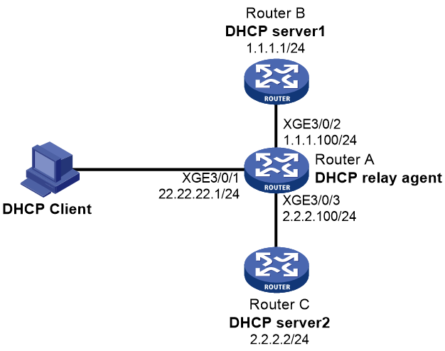
Procedure
1. Assign IP addresses to interfaces on the routers. (Details not shown.)
2. Configure Router B and Router C as DHCP servers. (Details not shown.)
3. Configure the DHCP relay agent on Router A:
# Enable DHCP.
<RouterA> system-view
[RouterA] dhcp enable
# Enable the DHCP relay agent on Ten-GigabitEthernet 3/0/1.
[RouterA] interface ten-gigabitethernet 3/0/1
[RouterA-Ten-GigabitEthernet3/0/1] dhcp select relay
# Specify the IP addresses of the DHCP servers.
[RouterA-Ten-GigabitEthernet3/0/1] dhcp relay server-address 1.1.1.1
[RouterA-Ten-GigabitEthernet3/0/1] dhcp relay server-address 2.2.2.2
# Specify the DHCP server selection algorithm as master-backup.
[RouterA-Ten-GigabitEthernet3/0/1] dhcp relay server-address algorithm master-backup
# Configure the DHCP relay agent to switch back to the master DHCP server 3 minutes after it switches to the backup DHCP server.
[RouterA-Ten-GigabitEthernet3/0/1] dhcp relay master-server switch-delay 3
[RouterA-Ten-GigabitEthernet3/0/1] quit
Verifying the configuration
# Verify that the DHCP client cannot obtain an IP address and that the following log is output in about 30 seconds.
DHCPR/3/DHCPR_SERVERCHANGE:
Switched to the server at 2.2.2.2 because the current server did not respond.
# Enable DHCP on the DHCP server at 1.1.1.1. (Details not shown.)
# Verify that the DHCP client cannot obtain an IP address and that the following log is output in about 3 minutes.
DHCPR/3/DHCPR_SWITCHMASTER:
Switched to the master DHCP server at 1.1.1.1.
# Verify that the DHCP client obtains an IP address. (Details not shown.)
Troubleshooting DHCP relay agent configuration
Failure of DHCP clients to obtain configuration parameters through the DHCP relay agent
Symptom
DHCP clients cannot obtain configuration parameters through the DHCP relay agent.
Solution
Some problems might occur with the DHCP relay agent or server configuration.
To locate the problem, enable debugging and execute the display command on the DHCP relay agent to view the debugging information and interface state information.
Check that:
· DHCP is enabled on the DHCP server and relay agent.
· The DHCP server has an IP pool on the same subnet as the DHCP clients.
· The DHCP server and DHCP relay agent can reach each other.
· The DHCP server address specified on the DHCP relay interface connected to the DHCP clients is correct.
Configuring the DHCP client
About DHCP client
With DHCP client enabled, an interface uses DHCP to obtain configuration parameters from the DHCP server, for example, an IP address.
Restrictions and guidelines: DHCP client configuration
The DHCP client configuration is supported only on Layer 3 Ethernet interfaces (or subinterfaces), VLAN interfaces, and Layer 3 aggregate interfaces.
DHCP client tasks at a glance
To configure a DHCP client, perform the following tasks:
1. Enabling DHCP client on an interface
2. Configuring a DHCP client ID for an interface
Perform this task if the DHCP client uses the client ID to obtain IP addresses.
3. (Optional.) Enabling duplicated address detection
4. (Optional.) Setting the DSCP value for DHCP packets sent by the DHCP client
Enabling DHCP client on an interface
Restrictions and guidelines
· If the number of IP address request failures reaches the system-defined amount, the DHCP client-enabled interface uses a default IP address.
· An interface can be configured to acquire an IP address in multiple ways. The new configuration overwrites the old.
· Secondary IP addresses cannot be configured on an interface that is enabled with the DHCP client.
· If the interface obtains an IP address on the same segment as another interface on the device, the interface does not use the assigned address. Instead, it requests a new IP address from the DHCP server.
Procedure
1. Enter system view.
system-view
2. Enter interface view.
interface interface-type interface-number
3. Configure an interface to use DHCP for IP address acquisition.
ip address dhcp-alloc
By default, an interface does not use DHCP for IP address acquisition.
Configuring a DHCP client ID for an interface
About this task
A DHCP client ID is added to the DHCP option 61 to uniquely identify a DHCP client. A DHCP server can assign IP addresses to clients based on their DHCP client IDs.
DHCP client ID includes an ID type and a type value. Each ID type has a fixed type value. You can specify a DHCP client ID by using one of the following methods:
· Use an ASCII string as the client ID. If an ASCII string is used, the type value is 00.
· Use a hexadecimal number as the client ID. If a hexadecimal number is used, the type value is the first two characters in the number.
· Use the MAC address of an interface to generate a client ID. If this method is used, the type value is 01.
The type value of a DHCP client ID can be displayed by the display dhcp server ip-in-use or display dhcp client command.
Restrictions and guidelines
Make sure the ID for each DHCP client is unique.
Procedure
1. Enter system view.
system-view
2. Enter interface view.
interface interface-type interface-number
3. Configure a DHCP client ID for the interface.
dhcp client identifier { ascii ascii-string | hex hex-string | mac interface-type interface-number }
By default, an interface generates the DHCP client ID based on its MAC address. If the interface has no MAC address, it uses the MAC address of the first Ethernet interface to generate its client ID.
Enabling duplicated address detection
About this task
DHCP client detects IP address conflict through ARP packets. An attacker can act as the IP address owner to send an ARP reply. The spoofing attack makes the client unable to use the IP address assigned by the server. As a best practice, disable duplicate address detection when ARP attacks exist on the network.
Procedure
1. Enter system view.
system-view
2. Enable duplicate address detection.
dhcp client dad enable
By default, the duplicate address detection feature is disabled on an interface.
Setting the DSCP value for DHCP packets sent by the DHCP client
About this task
The DSCP value of a packet specifies the priority level of the packet and affects the transmission priority of the packet.
Procedure
1. Enter system view.
system-view
2. Set the DSCP value for DHCP packets sent by the DHCP client.
dhcp client dscp dscp-value
By default, the DSCP value in DHCP packets sent by the DHCP client is 56.
Display and maintenance commands for DHCP client
Execute display command in any view.
|
Task |
Command |
|
Display DHCP client information. |
display dhcp client [ verbose ] [ interface interface-type interface-number ] |
DHCP client configuration examples
Example: Configuring DHCP client
Network configuration
As shown in Figure 23, Router B contacts the DHCP server through Ten-GigabitEthernet 3/0/1 to obtain an IP address, a DNS server address, and static route information. The DHCP client's IP address resides on subnet 10.1.1.0/24. The DNS server address is 20.1.1.1. The next hop of the static route to subnet 20.1.1.0/24 is 10.1.1.2.
The DHCP server uses Option 121 to assign static route information to DHCP clients. Figure 22 shows the Option 121 format. The destination descriptor field contains the following parts: subnet mask length and destination network address, both in hexadecimal notation. In this example, the destination descriptor is 18 14 01 01 (the subnet mask length is 24 and the network address is 20.1.1.0 in dotted decimal notation). The next hop address is 0A 01 01 02 (10.1.1.2 in dotted decimal notation).
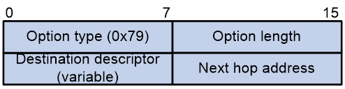
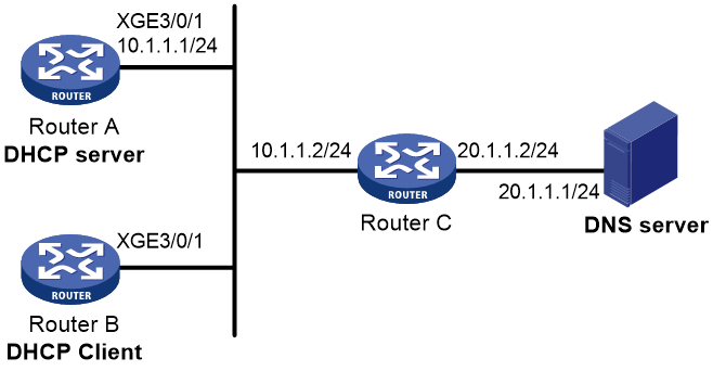
Procedure
1. Configure Router A:
# Specify an IP address for Ten-GigabitEthernet 3/0/1.
<RouterA> system-view
[RouterA] interface ten-gigabitethernet 3/0/1
[RouterA-Ten-GigabitEthernet3/0/1] ip address 10.1.1.1 24
[RouterA-Ten-GigabitEthernet3/0/1] quit
# Exclude an IP address from dynamic allocation.
[RouterA] dhcp server forbidden-ip 10.1.1.2
# Configure IP pool 0. Specify the subnet, lease duration, DNS server address, and a static route to subnet 20.1.1.0/24.
[RouterA] ip pool 0
[RouterA-ip-pool-0] network 10.1.1.0 mask 255.255.255.0
[RouterA-ip-pool-0] expired day 10
[RouterA-ip-pool-0] dns-list 20.1.1.1
[RouterA-ip-pool-0] option 121 hex 181401010A010102
[RouterA-ip-pool-0] quit
# Enable DHCP.
[RouterA] dhcp enable
2. Configure Router B:
# Configure Ten-GigabitEthernet 3/0/1 to use DHCP for IP address acquisition.
<RouterB> system-view
[RouterB] interface ten-gigabitethernet 3/0/1
[RouterB-Ten-GigabitEthernet3/0/1] ip address dhcp-alloc
[RouterB-Ten-GigabitEthernet3/0/1] quit
Verifying the configuration
# Display the IP address and other network parameters assigned to Router B.
[RouterB] display dhcp client verbose
Ten-GigabitEthernet3/0/1 DHCP client information:
Current state: BOUND
Allocated IP: 10.1.1.3 255.255.255.0
Allocated lease: 864000 seconds, T1: 331858 seconds, T2: 756000 seconds
Lease from May 21 19:00:29 2012 to May 31 19:00:29 2012
DHCP server: 10.1.1.1
Transaction ID: 0xcde72232
Classless static routes:
Destination: 20.1.1.0, Mask: 255.255.255.0, NextHop: 10.1.1.2
DNS servers: 20.1.1.1
Client ID type: acsii(type value=00)
Client ID value: 000c.29d3.8659-XGE3/0/1
Client ID (with type) hex: 0030-3030-632e-3239-
6433-2e38-3635-392d-
4574-6830-2f30-2f32
T1 will timeout in 3 days 19 hours 48 minutes 43 seconds
# Display the route information on Router B. The output shows that a static route to subnet 20.1.1.0/24 is added to the routing table.
[RouterB] display ip routing-table
Destinations : 11 Routes : 11
Destination/Mask Proto Pre Cost NextHop Interface
10.1.1.0/24 Direct 0 0 10.1.1.3 XGE3/0/1
10.1.1.3/32 Direct 0 0 127.0.0.1 InLoop0
20.1.1.0/24 Static 70 0 10.1.1.2 XGE3/0/1
10.1.1.255/32 Direct 0 0 10.1.1.3 XGE3/0/1
127.0.0.0/8 Direct 0 0 127.0.0.1 InLoop0
127.0.0.0/32 Direct 0 0 127.0.0.1 InLoop0
127.0.0.1/32 Direct 0 0 127.0.0.1 InLoop0
127.255.255.255/32 Direct 0 0 127.0.0.1 InLoop0
255.255.255.255/32 Direct 0 0 127.0.0.1 InLoop0
Configuring DHCP snooping
About DHCP snooping
DHCP snooping is a security feature for DHCP.
DHCP snooping works between the DHCP client and server, or between the DHCP client and DHCP relay agent. It guarantees that DHCP clients obtain IP addresses from authorized DHCP servers. Also, it records IP-to-MAC bindings of DHCP clients (called DHCP snooping entries) for security purposes.
DHCP snooping defines trusted and untrusted ports to make sure clients obtain IP addresses only from authorized DHCP servers.
· Trusted—A trusted port can forward DHCP messages correctly to make sure the clients get IP addresses from authorized DHCP servers.
· Untrusted—An untrusted port discards received DHCP-ACK and DHCP-OFFER messages to prevent unauthorized servers from assigning IP addresses.
DHCP snooping reads DHCP-ACK messages received from trusted ports and DHCPREQUEST messages to create DHCP snooping entries. A DHCP snooping entry includes the MAC and IP addresses of a client, the port that connects to the DHCP client, and the VLAN.
The following features need to use DHCP snooping entries:
· ARP fast-reply—Uses DHCP snooping entries to reduce ARP broadcast traffic. For more information, see "Configuring ARP fast-reply."
· IP source guard—Uses DHCP snooping entries to filter illegal packets on a per-port basis. For more information, see Security Configuration Guide.
· VLAN mapping—Uses DHCP snooping entries to replace service provider VLAN in packets with customer VLAN before sending the packets to clients. For more information, see Layer 2—LAN Switching Configuration Guide.
Application of trusted and untrusted ports
Configure ports facing the DHCP server as trusted ports, and configure other ports as untrusted ports.
As shown in Figure 24, configure the DHCP snooping device's port that is connected to the DHCP server as a trusted port. The trusted port forwards response messages from the DHCP server to the client. The untrusted port connected to the unauthorized DHCP server discards incoming DHCP response messages.
Figure 24 Trusted and untrusted ports
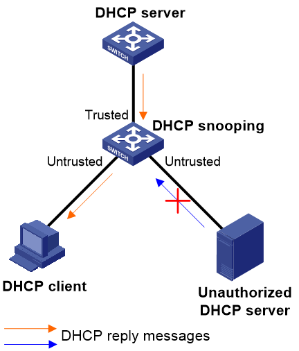
In a cascaded network as shown in Figure 25, configure the DHCP snooping devices' ports facing the DHCP server as trusted ports. To save system resources, you can enable only the untrusted ports directly connected to the DHCP clients to record DHCP snooping entries.
Figure 25 Trusted and untrusted ports in a cascaded network
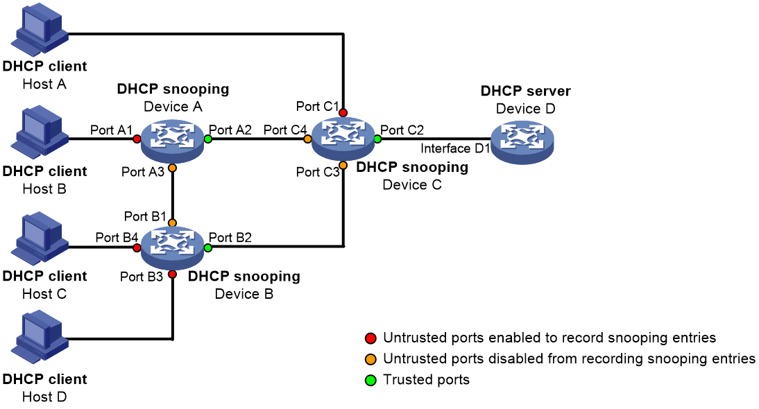
DHCP snooping support for Option 82
Option 82 records the location information about the DHCP client so the administrator can locate the DHCP client for security and accounting purposes. For more information about Option 82, see "Relay agent option (Option 82)."
DHCP snooping uses the same strategies as the DHCP relay agent to handle Option 82 for DHCP request messages, as shown in Table 4. If a response returned by the DHCP server contains Option 82, DHCP snooping removes Option 82 before forwarding the response to the client. If the response contains no Option 82, DHCP snooping forwards it directly.
|
If a DHCP request has… |
Handling strategy |
DHCP snooping… |
|
Option 82 |
Drop |
Drops the message. |
|
Keep |
Forwards the message without changing Option 82. |
|
|
Replace |
Forwards the message after replacing the original Option 82 with the Option 82 padded according to the configured padding format, padding content, and code type. |
|
|
No Option 82 |
N/A |
Forwards the message after adding the Option 82 padded according to the configured padding format, padding content, and code type. |
Restrictions and guidelines: DHCP snooping configuration
· The DHCP snooping configuration does not take effect on a Layer 2 Ethernet interface that is an aggregation member port. The configuration takes effect when the interface leaves the aggregation group.
· Specify the ports connected to authorized DHCP servers as trusted ports to make sure that DHCP clients can obtain valid IP addresses. The trusted ports and the ports connected to DHCP clients must be in the same VLAN.
· You can specify the following interfaces as trusted ports: Layer 2 Ethernet interfaces, Layer 2 aggregate interfaces, Layer 3 Ethernet interfaces, and Layer 3 aggregate interfaces. For more information about aggregate interfaces, see Layer 2—LAN Switching Configuration Guide.
DHCP snooping tasks at a glance
To configure DHCP snooping, perform the following tasks:
1. Configuring basic DHCP snooping
2. (Optional.) Configuring DHCP snooping support for Option 82
3. (Optional.) Configuring DHCP snooping entry auto backup
4. (Optional.) Setting the maximum number of DHCP snooping entries
5. (Optional.) Configuring DHCP snooping security features
6. (Optional.) Enabling DHCP snooping logging
Configuring basic DHCP snooping
1. Enter system view.
system-view
2. Enable DHCP snooping.
dhcp snooping enable
By default, DHCP snooping is disabled.
3. Enter interface view.
interface interface-type interface-number
This interface must connect to the DHCP server.
4. Specify the port as a trusted port.
dhcp snooping trust
By default, all ports are untrusted ports after DHCP snooping is enabled.
5. (Optional.) Enable the recording of DHCP snooping entries.
a. Return to system view.
quit
b. Enter interface view.
interface interface-type interface-number
This interface must connect to the DHCP client.
c. Enable the recording of DHCP snooping entries.
dhcp snooping binding record
By default, the recording of DHCP snooping entries is disabled.
Configuring DHCP snooping support for Option 82
Restrictions and guidelines
· The Option 82 configuration on a Layer 2 Ethernet interface that has been added to an aggregation group does not take effect unless the interface leaves the aggregation group.
· To support Option 82, you must configure Option 82 on both the DHCP server and the DHCP snooping device. For information about configuring Option 82 on the DHCP server, see "Enabling handling of Option 82."
· If Option 82 contains the device name, the device name must contain no spaces. Otherwise, DHCP snooping drops the message. You can use the sysname command to specify the device name. For more information about this command, see Fundamentals Command Reference.
· When receiving a double-tagged DHCP packet or working with QinQ, DHCP snooping uses "outer VLAN tag.inner VLAN tag" to fill the VLAN ID field of sub-option 1 in verbose padding format. For example, if the outer VLAN tag is 10 and the inner VLAN tag is 20, the VLAN ID field is 000a.0014. The hexadecimal digit a represents the outer VLAN tag 10, and the hexadecimal digit 14 represents the inner VLAN tag 20.
Procedure
1. Enter system view.
system-view
2. Enter interface view.
interface interface-type interface-number
3. Enable DHCP snooping to support Option 82.
dhcp snooping information enable
By default, DHCP snooping does not support Option 82.
4. (Optional.) Configure a handling strategy for DHCP requests that contain Option 82.
dhcp snooping information strategy { drop | keep | replace }
By default, the handling strategy is replace.
If the handling strategy is replace, configure a padding mode and padding format for Option 82. If the handling strategy is keep or drop, you do not need to configure any padding mode or padding format for Option 82.
5. (Optional.) Configure the padding mode and padding format for the Circuit ID sub-option.
dhcp snooping information circuit-id { [ vlan vlan-id ] string circuit-id | { normal | verbose [ node-identifier { mac | sysname | user-defined node-identifier } ] } [ format { ascii | hex } ] }
By default, the padding mode is normal and the padding format is hex for the Circuit ID sub-option.
If the device name (sysname) is configured as the padding content for sub-option 1, make sure the device name does not include spaces. Otherwise, the DHCP snooping device will fail to add or replace Option 82.
6. (Optional.) Configure the padding mode and padding format for the Remote ID sub-option.
dhcp snooping information remote-id { normal [ format { ascii | hex } ] | [ vlan vlan-id ] string remote-id | sysname }
By default, the padding mode is normal and the padding format is hex for the Remote ID sub-option.
Configuring DHCP snooping entry auto backup
About this task
The auto backup feature saves DHCP snooping entries to a backup file, and allows the DHCP snooping device to download the entries from the backup file at device reboot. The entries on the DHCP snooping device cannot survive a reboot. The auto backup helps the security features provide services if these features (such as IP source guard) must use DHCP snooping entries for user authentication.
Restrictions and guidelines
If you disable DHCP snooping with the undo dhcp snooping enable command, the device deletes all DHCP snooping entries, but entries stored in the backup file still exist. They are deleted next time the device updates the backup file.
Procedure
1. Enter system view.
system-view
2. Configure the DHCP snooping device to back up DHCP snooping entries to a file.
dhcp snooping binding database filename { filename | url url [ username username [ password { cipher | simple } string ] ] }
By default, the DHCP snooping device does not back up DHCP snooping entries.
With this command executed, the DHCP snooping device backs up DHCP snooping entries immediately and runs auto backup.
This command automatically creates the file if you specify a non-existent file.
3. (Optional.) Manually save DHCP snooping entries to the backup file.
dhcp snooping binding database update now
4. (Optional.) Set the waiting time after a DHCP snooping entry change for the DHCP snooping device to update the backup file.
dhcp snooping binding database update interval interval
By default, the DHCP snooping device waits 300 seconds to update the backup file after a DHCP snooping entry change. If no DHCP snooping entry changes, the backup file is not updated.
Setting the maximum number of DHCP snooping entries
About this task
Perform this task to prevent the system resources from being overused.
Procedure
1. Enter system view.
system-view
2. Enter interface view.
interface interface-type interface-number
3. Set the maximum number of DHCP snooping entries for the interface to learn.
dhcp snooping max-learning-num max-number
By default, the number of DHCP snooping entries for an interface to learn is unlimited.
Configuring DHCP snooping security features
Enabling DHCP starvation attack protection
About this task
A DHCP starvation attack occurs when an attacker constantly sends forged DHCP requests that contain identical or different sender MAC addresses in the chaddr field to a DHCP server. This attack exhausts the IP address resources of the DHCP server so legitimate DHCP clients cannot obtain IP addresses. The DHCP server might also fail to work because of exhaustion of system resources. For information about the fields of DHCP packet, see "DHCP message format."
You can prevent DHCP starvation attacks in the following ways:
· If the forged DHCP requests contain different sender MAC addresses, use the mac-address max-mac-count command to set the MAC learning limit on a Layer 2 port. For more information about the command, see Layer 2—LAN Switching Command Reference.
· If the forged DHCP requests contain the same sender MAC address, perform this task to enable MAC address check for DHCP snooping. This feature compares the chaddr field of a received DHCP request with the source MAC address field in the frame header. If they are the same, the request is considered valid and forwarded to the DHCP server. If not, the request is discarded.
Restrictions and guidelines
This feature only checks whether the chaddr field of a received DHCP-DISCOVER message is the same as the source MAC address in the frame header.
Procedure
1. Enter system view.
system-view
2. Enter interface view.
interface interface-type interface-number
3. Enable MAC address check.
dhcp snooping check mac-address
By default, MAC address check is disabled.
Enabling DHCPREQUEST attack protection
About this task
DHCPREQUEST messages include DHCP lease renewal packets, DHCP-DECLINE packets, and DHCP-RELEASE packets. This feature prevents the unauthorized clients that forge the DHCPREQUEST messages from attacking the DHCP server.
Attackers can forge DHCP lease renewal packets to renew leases for legitimate DHCP clients that no longer need the IP addresses. These forged messages disable the victim DHCP server from releasing the IP addresses.
Attackers can also forge DHCP-DECLINE or DHCP-RELEASE packets to terminate leases for legitimate DHCP clients that still need the IP addresses.
To prevent such attacks, you can enable DHCPREQUEST check. This feature uses DHCP snooping entries to check incoming DHCPREQUEST messages.
· If a matching entry is found for a message, this feature compares the entry with the message information.
¡ If they are consistent, the message is considered as valid and forwarded to the DHCP server.
¡ If they are different, the message is considered as a forged message and is discarded.
· If no matching entry is found, the message is considered valid and forwarded to the DHCP server.
Procedure
1. Enter system view.
system-view
2. Enter interface view.
interface interface-type interface-number
3. Enable DHCPREQUEST check.
dhcp snooping check request-message
By default, DHCPREQUEST check is disabled.
Configuring a DHCP packet blocking port
About this task
Perform this task to configure a port as a DHCP packet blocking port. This blocking port drops all incoming DHCP requests.
Procedure
1. Enter system view.
system-view
2. Enter interface view.
interface interface-type interface-number
3. Configure the port to block DHCP requests.
dhcp snooping deny
By default, the port does not block DHCP requests.
|
|
CAUTION: To avoid IP address acquisition failure, configure a port to block DHCP packets only if no DHCP clients are attached to it. |
Enabling DHCP snooping logging
About this task
The DHCP snooping logging feature enables the DHCP snooping device to generate DHCP snooping logs and send them to the information center. For information about the log destination and output rule configuration in the information center, see Network Management and Monitoring Configuration Guide.
Restrictions and guidelines
As a best practice, disable this feature if the log generation affects the device performance.
Procedure
1. Enter system view.
system-view
2. Enable DHCP snooping logging.
dhcp snooping log enable
By default, DHCP snooping logging is disabled.
Display and maintenance commands for DHCP snooping
Execute display commands in any view, and reset commands in user view.
|
Task |
Command |
|
Display DHCP snooping entries. |
display dhcp snooping binding [ ip ip-address [ vlan vlan-id ] ] [ verbose ] |
|
Display Option 82 configuration information on the DHCP snooping device. |
display dhcp snooping information { all | interface interface-type interface-number } |
|
Display DHCP packet statistics on the DHCP snooping device. |
display dhcp snooping packet statistics [ slot slot-number ] |
|
Display information about trusted ports. |
display dhcp snooping trust |
|
Display information about the file that stores DHCP snooping entries. |
display dhcp snooping binding database |
|
Clear DHCP snooping entries. |
reset dhcp snooping binding { all | ip ip-address [ vlan vlan-id ] } |
|
Clear DHCP packet statistics on the DHCP snooping device. |
reset dhcp snooping packet statistics [ slot slot-number ] |
DHCP snooping configuration examples
Example: Configuring basic DHCP snooping
Network configuration
As shown in Figure 26, Router B is connected to the authorized DHCP server through Ten-GigabitEthernet 3/0/1, to the unauthorized DHCP server through Ten-GigabitEthernet 3/0/3, and to the DHCP client through Ten-GigabitEthernet 3/0/2.
Configure only the port connected to the authorized DHCP server to forward the responses from the DHCP server. Enable the DHCP snooping device to record clients' IP-to-MAC bindings by reading DHCP-ACK messages received from the trusted port and the DHCPREQUEST messages.
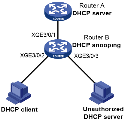
Procedure
# Enable DHCP snooping.
<RouterB> system-view
[RouterB] dhcp snooping enable
# Configure Ten-GigabitEthernet 3/0/1 as a trusted port.
[RouterB] interface ten-gigabitethernet 3/0/1
[RouterB-Ten-GigabitEthernet3/0/1] dhcp snooping trust
[RouterB-Ten-GigabitEthernet3/0/1] quit
# Enable recording clients' IP-to-MAC bindings on Ten-GigabitEthernet 3/0/2.
[RouterB] interface ten-gigabitethernet 3/0/2
[RouterB-Ten-GigabitEthernet3/0/2] dhcp snooping binding record
[RouterB-Ten-GigabitEthernet3/0/2] quit
Verifying the configuration
# Verify that the DHCP client can obtain an IP address and other configuration parameters only from the authorized DHCP server. (Details not shown.)
# Display the DHCP snooping entry recorded for the client.
[RouterB] display dhcp snooping binding
Example: Configuring DHCP snooping support for Option 82
Network configuration
As shown in Figure 27, enable DHCP snooping and configure Option 82 on Router B as follows:
· Configure the handling strategy for DHCP requests that contain Option 82 as replace.
· On Ten-GigabitEthernet 3/0/2, configure the padding content for the Circuit ID sub-option as company001 and for the Remote ID sub-option as device001.
· On Ten-GigabitEthernet 3/0/3, configure the padding mode for the Circuit ID sub-option as verbose, access node identifier as sysname, and padding format as ascii. Configure the padding content for the Remote ID sub-option as device001.
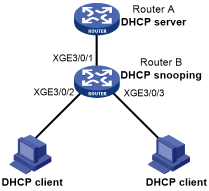
Procedure
# Enable DHCP snooping.
<RouterB> system-view
[RouterB] dhcp snooping enable
# Configure Ten-GigabitEthernet 3/0/1 as a trusted port.
[RouterB] interface ten-gigabitethernet 3/0/1
[RouterB-Ten-GigabitEthernet3/0/1] dhcp snooping trust
[RouterB-Ten-GigabitEthernet3/0/1] quit
# Configure Option 82 on Ten-GigabitEthernet 3/0/2.
[RouterB] interface ten-gigabitethernet 3/0/2
[RouterB-Ten-GigabitEthernet3/0/2] dhcp snooping information enable
[RouterB-Ten-GigabitEthernet3/0/2] dhcp snooping information strategy replace
[RouterB-Ten-GigabitEthernet3/0/2] dhcp snooping information circuit-id string company001
[RouterB-Ten-GigabitEthernet3/0/2] dhcp snooping information remote-id string device001
[RouterB-Ten-GigabitEthernet3/0/2] quit
# Configure Option 82 on Ten-GigabitEthernet 3/0/3.
[RouterB] interface ten-gigabitethernet 3/0/3
[RouterB-Ten-GigabitEthernet3/0/3] dhcp snooping information enable
[RouterB-Ten-GigabitEthernet3/0/3] dhcp snooping information strategy replace
[RouterB-Ten-GigabitEthernet3/0/3] dhcp snooping information circuit-id verbose node-identifier sysname format ascii
[RouterB-Ten-GigabitEthernet3/0/3] dhcp snooping information remote-id string device001
Verifying the configuration
# Display Option 82 configuration information on Ten-GigabitEthernet 3/0/2 and Ten-GigabitEthernet 3/0/3 on the DHCP snooping device.
[RouterB] display dhcp snooping information
Configuring the BOOTP client
About BOOTP client
BOOTP client application
An interface that acts as a BOOTP client can use BOOTP to obtain information (such as IP address) from the BOOTP server.
To use BOOTP, an administrator must configure a BOOTP parameter file for each BOOTP client on the BOOTP server. The parameter file contains information such as MAC address and IP address of a BOOTP client. When a BOOTP client sends a request to the BOOTP server, the BOOTP server searches for the BOOTP parameter file and returns the corresponding configuration information.
BOOTP is usually used in relatively stable environments. In network environments that change frequently, DHCP is more suitable.
Because a DHCP server can interact with a BOOTP client, you can use the DHCP server to assign an IP address to the BOOTP client. You do not need to configure a BOOTP server. The DHCP server will assign an IP address to the BOOTP client based on the IP address allocation sequence.
Obtaining an IP address dynamically
A BOOTP client dynamically obtains an IP address from a BOOTP server as follows:
1. The BOOTP client broadcasts a BOOTP request, which contains its own MAC address.
2. Upon receiving the request, the BOOTP server searches the configuration file for the IP address and other information according to the BOOTP client's MAC address.
3. The BOOTP server returns a BOOTP response to the BOOTP client.
4. The BOOTP client obtains the IP address from the received response.
A DHCP server can take the place of the BOOTP server in the following dynamic IP address acquisition.
Protocols and standards
· RFC 951, Bootstrap Protocol (BOOTP)
· RFC 2132, DHCP Options and BOOTP Vendor Extensions
· RFC 1542, Clarifications and Extensions for the Bootstrap Protocol
Configuring an interface to use BOOTP for IP address acquisition
1. Enter system view.
system-view
2. Enter interface view.
interface interface-type interface-number
BOOTP client configuration applies only to Layer 3 Ethernet interfaces (including subinterfaces), Layer 3 aggregate interfaces, and VLAN interfaces.
3. Configure an interface to use BOOTP for IP address acquisition.
ip address bootp-alloc
By default, an interface does not use BOOTP for IP address acquisition.
Display and maintenance commands for BOOTP client
Execute display command in any view.
|
Task |
Command |
|
Display BOOTP client information. |
display bootp client [ interface interface-type interface-number ] |
BOOTP client configuration examples
Example: Configuring BOOTP client
Network configuration
As shown in Figure 28, Ten-GigabitEthernet 3/0/1 of Router B connects to the LAN to obtain an IP address from the DHCP server by using BOOTP.
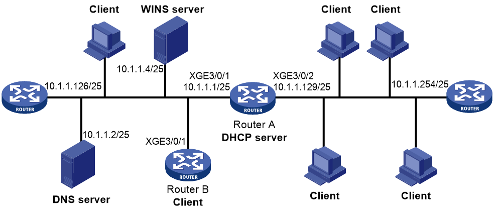
Prerequisites
To make the BOOTP client obtain an IP address from the DHCP server, configure the DHCP server. For more information, see "DHCP server configuration examples."
Procedure
The following describes the configuration on Router B, which acts as a client.
# Configure Ten-GigabitEthernet 3/0/1 to use BOOTP to obtain an IP address.
<RouterB> system-view
[RouterB] interface ten-gigabitethernet 3/0/1
[RouterB-Ten-GigabitEthernet3/0/1] ip address bootp-alloc
Verifying the configuration
# Display the IP address assigned to the BOOTP client.
[RouterB] display bootp client