- Table of Contents
- Related Documents
-
| Title | Size | Download |
|---|---|---|
| 01-BIER configuration | 563.52 KB |
Contents
Assigning the device to a sub-domain
Specifying a BFR ID for a BIER edge device
Configuring BIER encapsulation
Configuring the encapsulation type, BSL, and maximum SI
Configuring a reserved address for the G-BIER multicast policy
Configuring a TTL processing mode on a BIER edge device
Configuring static cross-AS BIER
Configuring BGP-based cross-AS BIER
Enabling the device to exchange routes with BIER path attributes with a peer or peer group
Enabling BGP BFR prefix proxying
Enabling BGP to redistribute the BIER information from an IGP
Display and maintenance commands for BIER
Example: Configuring intra-AS BIER-based MVPN
Example: Configuring BIER-based MVPN for the public instance
Configuring BIER
About BIER
Bit Index Explicit Replication (BIER) is a new architecture for the forwarding of multicast data packets. BIER encapsulates the destination nodes of multicast packets in a bit string. It does not require a protocol for explicitly building multicast distribution trees, nor does it require intermediate nodes to maintain any per-flow state.
BIER network structure
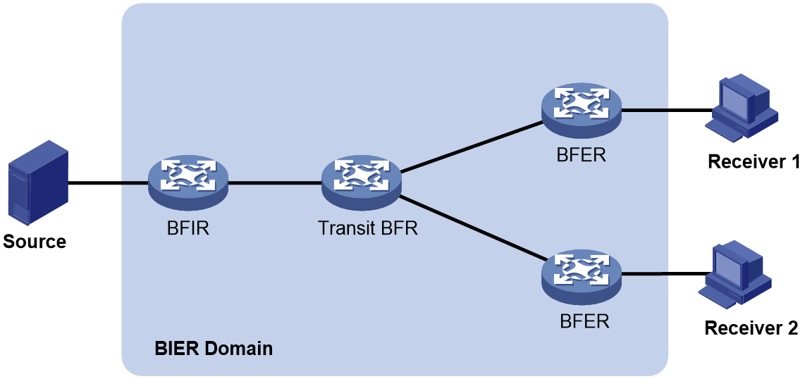
A router that supports BIER is known as a Bit-Forwarding Router (BFR). As shown in Figure 1, a BIER network consists of the following BFRs:
· Bit Forwarding Ingress Router (BFIR)—A multicast data packet enters a BIER domain at a BFIR. A BFIR encapsulates the multicast data packet as a BFIR packet.
· Transit BFR—A transit BFR receives a multicast data packet from one BFR to another BFR in the same BIER domain.
· Bit Forwarding Egress Router (BFER)—A multicast data packet leaves a BIER domain at a BFER. A BFER decapsulates the multicast data packet and sends it to multicast receivers.
Figure 1 BIER network structure
Basic concepts
BIER domain and BIER sub-domain
All BFRs in a network are referred to as a BIER domain. A BIER domain can contain one or more sub-domains. Each sub-domain is identified by a sub-domain ID. All BFIRs and BFERs in a sub-domain are called BIER edge devices.
BFR ID
A BFR ID uniquely identifies a BIER edge device in a sub-domain. A transit BFR does not need to have a BFR ID.
BFR prefix
A BFR prefix is an IP address that uniquely identifies a BFR in a sub-domain. A BFR prefix must be routable in the sub-domain and can only be the IP address of a loopback interface.
Bit string
A bit string represents a set of BIER edge devices, with each bit corresponding to a BFR ID, starting from the rightmost position. The bit string length (BSL) refers to the number of bits in the bit string. A bit string with three bits can identify a maximum of three BIER edge devices. The BIER edge device with BFR ID 1 is represented as 001.
Set identifier
When the number of BFR IDs is greater than the number of bits in the bit string, the bit string needs to be divided into sets identified by set identifiers (SI). For example, if the maximum BFR ID is 10 in a BIER sub-domain and the bit string length is 4, the bit string needs to be divided into three SIs (SI 0, SI 1, and SI 2). The maximum SI is (Maximum BFR ID–1)/BSL rounded down to the nearest integer.
Bit Index Routing Table
The Bit Index Routing Table (BIRT) is generated based on the BIER information ((sub-domain, BSL, and BFR ID) and routing information carried by IGP. The BIRT is used to guide the forwarding of BIER packets in a BIER sub-domain.
Forwarding Bit Mask
The Forwarding Bit Mask (F-BM) represents a set of edge nodes in a BIER sub-domain that are reachable through a BFR neighbor (BFR-NBR). The bit mask is obtained by taking the logical OR of the bit strings of all reachable edge nodes.
Bit Index Forwarding Table
The Bit Index Forwarding Table (BIFT) can guide the per-hop forwarding of multicast traffic in a BIER sub-domain.
The BIFT is used to map from the BFR ID of a BFER to the corresponding F-BM and BFR-NBR. Multiple BIFT can exist on a BFR. Each BIFT is identified by a combination of the BSL, SD, and SI).
Layering
As specified in RFC 8279, the BIER architecture consists of three layers: routing overlay, BIER layer, and multicast flow overlay.
Routing overlay
The routing overlay uses an IGP (only IS-IS is supported) to flood BIER information through extended TLVs in a BIER sub-domain. A BFR generates routes to all BFR prefixes (BFR IDs) based on the IGP. Therefore, the routing overlay establishes adjacencies between pairs of BFRs and determines one or more best paths from a given BFR to a given set of BFRs.
BIER layer
The BIER layer consists of the protocols and procedures that are used in order to transmit a multicast data packet across a BIER domain.
1. A BFR advertises the BIER information to other BFRs in the BIER domain through IGP.
2. Other BFRs generate a BIRT and a BIFT according to the advertised information.
3. An intermediate BFR forwards a BIER-encapsulated packet by looking up the BIFT table.
Multicast flow overlay
The multicast flow overlay is responsible for control plane processing. It collects join and leave messages of multicast groups between BFIRs and BFERs. When a BFIR receives a multicast data packet from outside the BIER domain, the BFIR determines the set of BFERs for that packet. When a BFER receives a BIER-encapsulated packet from inside the BIER domain, the BFER decapsulates the packet and forwards it.
BIER packet format
RFC 8279 defines multiple encapsulation types for BIER. Different encapsulation types have different packet formats. Only generalized BIER (G-BIER) is supported in the current software version.
Proposed by Chine Mobile, G-BIER revised the BIER header to adapt to IPv6.
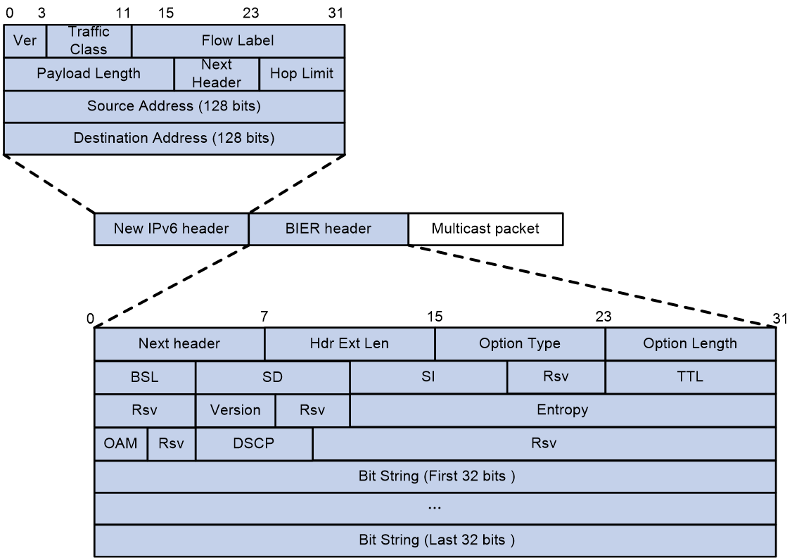
G-BIER encapsulates a multicast data packet as a G-BIER packet by adding a new IPv6 header and a BIER header. As shown in Figure 2, the Next Header field in the IPv6 header is 60, which indicates that the next header is Destination Options Header (DOH).
G-BIER uses the following conventions related to the following fields in the new IPv6 header:
· Source Address—The source address is the multicast service source address and remains unchanged when a multicast packet is transmitted over a public network. For more information about multicast service source address, see multicast VPN configuration in IP Multicast Configuration Guide.
· Destination Address—The destination address is the multicast policy reserved address for BIER forwarding. This address must be routable in a sub-domain.
The BIER header contains the following fields:
· Next Header—An 8-bit field to identify the type of the next header.
· Hdr Ext Len—An 8-bit field to indicate the length of the IPv6 extension header.
· Option Type (TO)—An 8-bit field, which is fixed at G-BIER.
· BSL—A 4-bit field to identify the length in bits of the BitString.
· SD—An 8-bit field to indicate the ID of the BIER sub-domain.
· SI—An 8-bit field to indicate the set identifier.
· Rsv—A 4-bit, reserved field.
· TTL—An 8-bit Time to Live field to prevent loops.
· Version—A 4-bit field to identify the version of the BIER header, which is fixed at 0.
· Entropy—A 20-bit field to specify an entropy value used for load-balancing purposes when there are ECMP paths. The load-balancing procedure will choose the same path for any two packets that have the same entropy value and the same BitString.
· OAM—A 4-bit field that can be used for OAM purposes. The device value of this field is 0.
· DSCP—A 7-bit field to indicate the forwarding priority of the packet.
· Bit String—This field holds the BitString that, together with the packet's SI and SD, identifies the destination BFERs for this packet.
BIER forwarding process
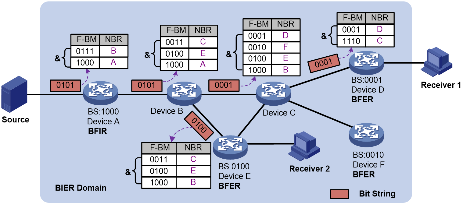
As shown in Figure 3, Receiver 1 is a multicast receiver. Device A learned the BFR IDs and BFR prefixes of Device D and Device E through MVPN routes. Device A is in the same sub-domain as Device D and Device E. Each device in the sub-domain calculated a BIFT entry to another device.
When Device A receives a packet from outside the domain:
1. Device A learns the BFR IDs and BFR prefixes of Device D and Device E through MVPN routes. Device A translates the BFR IDs of Device D and Device E to bit strings according to the BSL and SI configured in the sub-domain and obtains bit string 0101 by taking a logical OR operation of the two bit strings. Device A performs a logical AND operation on bit string 0101 and each F-BM in the BIFT derived from the triple (BSL, sub-domain, and SI) and encapsulates bit string 0101 in the BIER header. Then, Device A makes a copy of the packet and sends the copy to the corresponding neighbor (Device B in this example). If the result of the logical AND operation is 0, the packet is not copied to the corresponding neighbor (Device A in this example).
2. After receiving the BIER packet, Device B reads BS 0101 and performs a logical AND operation on bit string 0101 and each F-BM in the BIFT. If the result is not 0, Device B copies the packet, and modifies the BS value in the copy as 0001, and sends the copy to Device C. Similarly, Device B modifies the BS value in the copy as 0101 and sends the copy to Device E.
3. After receiving the BIER packet, Device C performs the same logical AND operation as Device B in step 2. Then, Device C copies the packet, modifies the BS value in the copy as 0001, and sends the copy to Device D.
4. After receiving the BIER packet, Device E determines that the result of the logical AND operation on its F-BM and BS value 0100 in the packet is not 0. Device E decapsulates the BIER packet and sends the multicast packet to downstream receivers according to the multicast routing table.
5. After receiving the BIER packet, Device D determines that the result of the logical AND operation on its F-BM and BS value 0100 in the packet is not 0. Device D decapsulates the BIER packet and sends the multicast packet to downstream receivers according to the multicast routing table.
Figure 3 BIER forwarding process
BIER benefits
BIER has the following benefits:
· Protocol simplification—BIER does not require a protocol for explicitly building multicast distribution trees. BIER uses IGP or BGP extensions to exchange control plane data without RPs.
· Flow state independent—BIER does not require intermediate nodes to maintain any per-flow state. BIER establishes a BIFT on each BFR based on the topology. A BIFT calculates routes and updates entries based on node or link changes and is not affected by multicast source and receiver changes.
· Layered architecture—The BIER layer decouples the routing layer and multicast flow overlay. A existing network can be mitigated to BIER smoothly by adding the following capabilities:
¡ BEIR capabilities on the routing layer.
¡ BIER tunnel capabilities on the multicast flow overlay.
¡ BIER encapsulation, decapsulation, and forwarding capabilities on the data plane.
BIER application scenarios
BIER is used in the following scenarios:
· Large-scale multicast network—BIER does not need to build a multicast distribution tree for each multicast flow or maintain per-flow state. BIER, as a public network tunneling technology to carry private network traffic, replaces the traditional P2MP tunneling or public network PIM. For more information about BIER-based multicast VPN, see multicast VPN in IP Multicast Configuration Guide.
· SDN network—A multicast user does not need to join the multicast distribution tree hop by hop. It sends join messages only to the leaf node and root node. BIER is applicable to a SDN network where the controller distributes multicast traffic after collecting multicast destinations.
Cross-AS BIER
Cross-AS BIER indicates that a BIER network spans multiple ASs and multicast traffic passes through multiple ASs during BIER forwarding. An IGP can flood BIER information within an AS and cannot generate cross-AS BIER forwarding entries. Cross-AS BIER requires that a BIER node can obtain the BIER information (such as BFR ID) of BIER nodes in another AS. The device supports implementing cross-AS BIER through static configuration and BGP advertisement.
Static cross-AS BIER
You implement cross-AS BIER by manually specifying the BFR neighbor in another domain and the BFR ID range of BIER edge devices that can be reached through the BFR neighbor.
BGP-based cross-AS BIER
BGP can transfer BIER information between ASs. The BIER information can guide the forwarding of BIER packets. BGP encapsulates the following BIER information in UPDATE messages:
· BFR prefix—Encapsulated in the NLRI field.
· BIER Path Attribute—A new attribute that contains information such as BIER sub-domain, BFR ID, BSL, and MPRA.
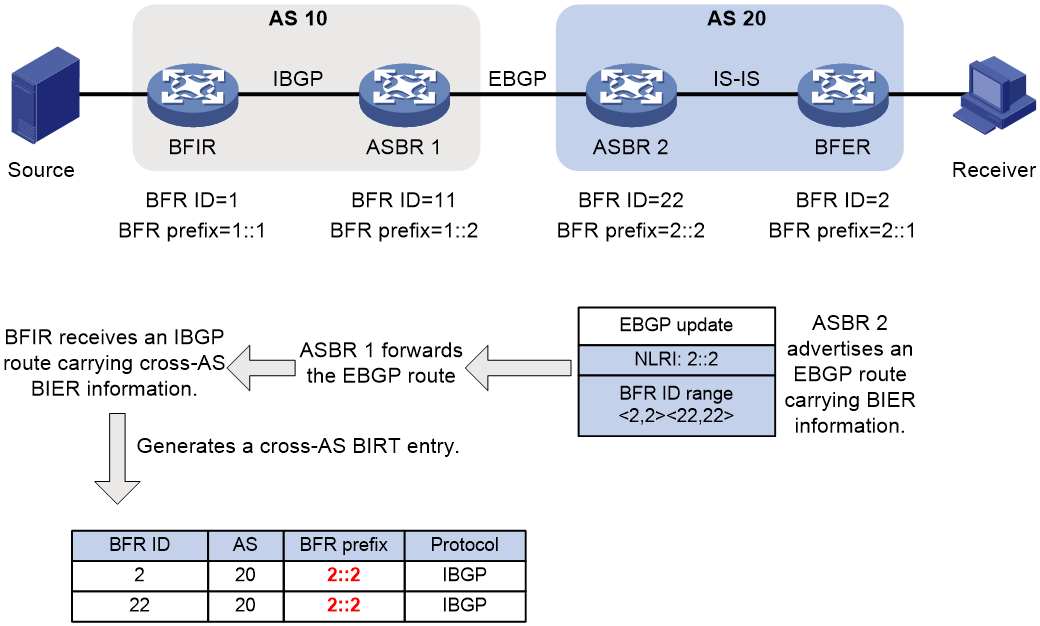
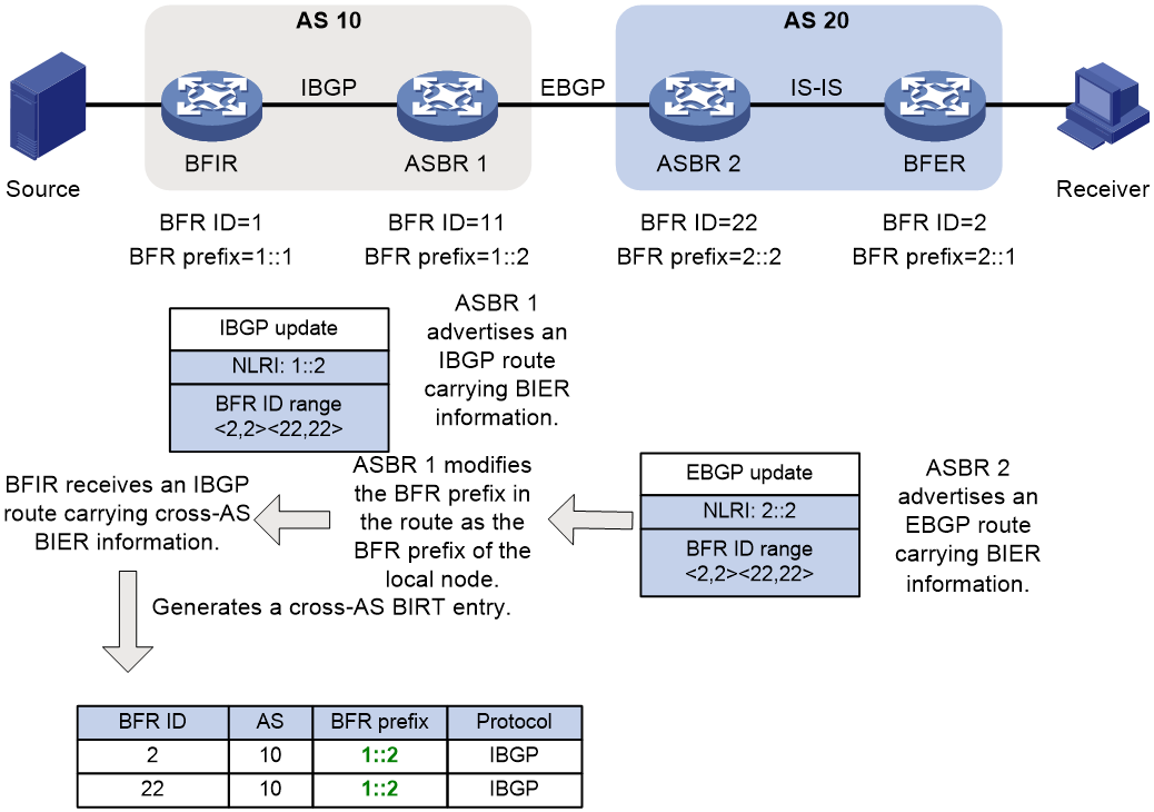
As shown in Figure 4, the BIER network spans AS 10 and AS 20. IS-IS is used to transfer BIER information in AS 20, and IBGP is used to transfer BIER information in AS 10. On ASBR 2, BIER information collected by IS-IS in AS 20 can be imported to BGP and then sent to ASBR 1 through an EBGP session. ASBR 1 forwards an EBGP route to the BFIR. The BFIR generates a cross-AS BIRT entry based on the BIER information carried in the received IBGP route. The BFR prefix of the BFR ID of the BFER is the BFR prefix of ASBR 2 (2::2). The BFIR uses ASBR 2 as the next hop when forwarding multicast packets.
|
|
NOTE: Carried in a BGP route, the BFR ID range is used by the BIER to learn BFR IDs in another BIER domain. |
Figure 4 BGP-based cross-AS BIER
To successfully forward BIER packets, the BFIR must obtain the route information of ASBR 2. The BGP BFR prefix proxy function enables the BFIR successfully forward BIER packets without the route information of ASBR 2. A node enabled with BGP BFR prefix proxying is called a BFR proxy node. A BFR proxy node advertises cross-AS BFR ID range information. The nodes in BIER domain use the BFR proxy node as the next hop when forwarding BIER packets across ASs.
A BFR proxy node does not directly forward routes carrying BIER information learned from a BGP peer to other BGP peers and advertises them as follows:
1. Advertises the BIER information (including BFR ID range information) in learned routes to the BIER module.
2. The BIER module modifies the BFR prefix in the BIER information as the BFR prefix of the local node and summarizes received BFR ID range information.
|
|
NOTE: Modifying the BFR prefix can prevent BFR prefix information from being leaked out of a BIER domain. For example, an ISP deploys a BIER network that spans the provincial headquarters and the MANs. If BGP BFR prefix proxying is enabled on the edge devices at the provincial headquarters, devices in the MANs can obtain only the BFR prefix information of the BFR proxy nodes. This prevents the BFR prefix information of other nodes at the provincial headquarters from being leaked out to the MANs. |
3. The BIER module advertises the modified BIER information to the BGP module. The BGP module generates a BGP route that carries the modified BIER information (including BFR ID range information) and sends it to BGP peers.
4. After receiving the BGP route, an IBGP or EBPG peer generates cross-AS BIRT entry. The BRF prefix of the edge node is the BRF prefix of the BFR proxy node.
When a device forwards a cross-AS packet, it will encapsulate the MPRA of the BFR proxy node and sends the packet to the BFR proxy node. The BFR proxy node forwards the received packet according to the BIFT.
As shown in Figure 5, after being enabled with BGP BFR prefix proxying, ASBR 1 generates an IBGP route based on the BGP route received from ASBR 2 and send the IBGP route to the BFIR. The IBGP route retains the BFR ID range information in the received BGP route and encapsulates the BFR prefix of the local node (in place of the BFR prefix in the received BGP route) in the NLRI field. In the cross-AS BIRT entry generated by the BFIR, the BFR prefix of the BFR ID of the BFER is the BFR prefix of ASBR 1 (2::2). The BFIR uses ASBR 1 as the next hop when forwarding multicast packets.
Figure 5 BGP BFR prefix proxying
Protocols and standards
· RFC 8279, Multicast Using Bit Index Explicit Replication (BIER)
· RFC 8296, Encapsulation for Bit Index Explicit Replication (BIER) in MPLS and Non-MPLS Networks
· RFC 8401, Bit Index Explicit Replication (BIER) Support via IS-IS
· RFC 8556, Multicast VPN Using Bit Index Explicit Replication
· draft-ietf-bier-idr-extensions-07
BIER tasks at a glance
To configure BIER, perform the following tasks:
2. Assigning the device to a sub-domain
3. Specifying a BFR ID for a BIER edge device
5. Configuring BIER encapsulation
¡ Configuring the encapsulation type, BSL, and maximum SI
¡ Configuring a reserved address for the G-BIER multicast policy
6. (Optional.) Configuring a TTL processing mode on a BIER edge device
7. (Optional.) Configuring static cross-AS BIER
8. (Optional.) Configuring BGP-based cross-AS BIER
¡ Enabling the device to exchange routes with BIER path attributes with a peer or peer group
¡ Enabling BGP BFR prefix proxying
¡ Enabling BGP to redistribute the BIER information from an IGP
Enabling BIER
About this task
Perform this task on BFRs in the public network in BIER-based MVPN to transmit multicast traffic over a BIER tunnel.
Procedure
1. Enter system view.
system-view
2. Enable BIER and enter BIER view.
bier
By default, BIER is disabled.
Assigning the device to a sub-domain
About this task
In a BIER domain, BIER forwarding is performed in a sub-domain. You must add a device to a sub-domain.
Procedure
1. Enter system view.
system-view
2. Enter BIER view.
bier
3. Assign the device to a sub-domain.
sub-domain sub-domain-id ipv6
By default, the device does not belong to any sub-domain.
Specifying a BFR ID for a BIER edge device
About this task
In a BIER sub-domain, a BFIR or BFER must have a unique BFR ID. If a BIER edge device belongs to more than one sub-domain, it can have the same or different BFR IDs in different sub-domains.
Restrictions and guidelines
As a best practice to reduce the number of Sis and the number of encapsulated packets, configure contiguous BFR IDs.
Procedure
1. Enter system view.
system-view
bier
3. Enter sub-domain view.
sub-domain sub-domain-id ipv6
4. Specify a BFR ID for the device.
bfr-id bfr-id
By default, the device does not have a BFR ID.
Specifying a BFR prefix
About this task
As an equivalent to a router ID in a routing protocol, a BFR prefix identifies a BFR in a sub-domain. In a sub-domain, a BFR must have a unique BFR prefix that is routable.
Restrictions and guidelines
Only the IP address of a loopback interface can be configured as a BFR prefix. After the IP address of a loopback interface is configured as a BFR prefix, the loopback interface cannot be deleted.
If a BFR belongs to more than one sub-domain, it can have the same or different BFR prefixes in different sub-domains.
Procedure
1. Enter system view.
system-view
2. Enter BIER view.
bier
3. Enter sub-domain view.
sub-domain sub-domain-id ipv6
4. Specify a BFR prefix for the device.
bfr-prefix interface interface-type interface-number
By default, the device does not have a BFR prefix.
Configuring BIER encapsulation
Configuring the encapsulation type, BSL, and maximum SI
Restrictions and guidelines
BFRs in the same sub-domain must have the same BSL.
The maximum SI is (Maximum BFR ID–1)/BSL rounded down to the nearest integer. For example, if the maximum BFR ID is 10 in a BIER sub-domain and the bit string length is 4, the bit string needs to be divided into three SIs (SI 0, SI 1, and SI 2).
Procedure
1. Enter system view.
system-view
2. Enter BIER view.
bier
3. Enter sub-domain view.
sub-domain sub-domain-id ipv6
4. Configure the encapsulation type, BSL, and maximum SI.
encapsulation-type g-bier bsl bsl-value max-si max-si-value
By default, the encapsulation type, BSL, and maximum SI are not configured.
Configuring a reserved address for the G-BIER multicast policy
About this task
When the encapsulation type is G-BIER, you must configure a routable IPv6 address reserved for the G-BIER multicast policy in a sub-domain. The IPv6 address is carried in the IS-IS sub-sub-TLV to be advertised to neighbors as the destination IPv6 address in G-BIER packets.
When a BFR receives a G-BIER packet, it compares the destination IPv6 address in the packet with the configured IPv6 address. If they are the same, the BFR performs BIER forwarding on the packet. If they are different, the BFR performs IP forwarding on the packet.
Restrictions and guidelines
A BFR must have a unique reserved address in a sub-domain.
Before configuring a reserved address, you must configure the encapsulation type as G-BIER by using the encapsulation-type command.
Procedure
1. Enter system view.
system-view
2. Enter BIER view.
bier
3. Enter sub-domain view.
sub-domain sub-domain-id ipv6
4. Configure a reserved address for the G-BIER multicast policy.
g-bier mpra ipv6-address
By default, no reserved address for the G-BIER multicast policy is configured.
Configuring a TTL processing mode on a BIER edge device
About this task
When acting as a public network tunnel, BIER can process TTLs in the following modes:
· uniform—When the ingress node of a public network tunnel adds a BIER header to a multicast packet, it copies the TTL value to the TTL field of the BIER packet. When a BFER decapsulates the BIER packet, it copies the TTL value back to the TTL field of the multicast packet. In this mode, nodes in the public network are visible to packets in the user network. The TTL value of the BIER packet decreases by 1 per hop in the BIER tunnel. A tracert operation can display the actual path that the packet travels.
· pipe—When the ingress node of a public network tunnel adds a BIER header to a multicast packet, it populates the TTL field in the BIER with the configured TTL value instead of copying the TTL value of the multicast packet. When a BFER decapsulates the BIER packet, it does not modify the TTL value the multicast packet. In this mode, nodes in the public network are invisible to packets in the user network. The TTL value of the BIER packet decreases by 1 per hop in the BIER tunnel. A tracert operation does not display each node in the public network so the public network structure is hidden.
Restrictions and guidelines
The BFIR and BFERs must be configured with the same TTL processing mode.
Procedure
1. Enter system view.
system-view
2. Enter BIER view.
bier
3. Enter sub-domain view.
sub-domain sub-domain-id ipv6
4. Configure a TTL processing mode.
ttl-mode { pipe ttl ttl-value | uniform }
The default setting is pipe on a BFIR and uniform on a BFER.
Configuring static cross-AS BIER
About this task
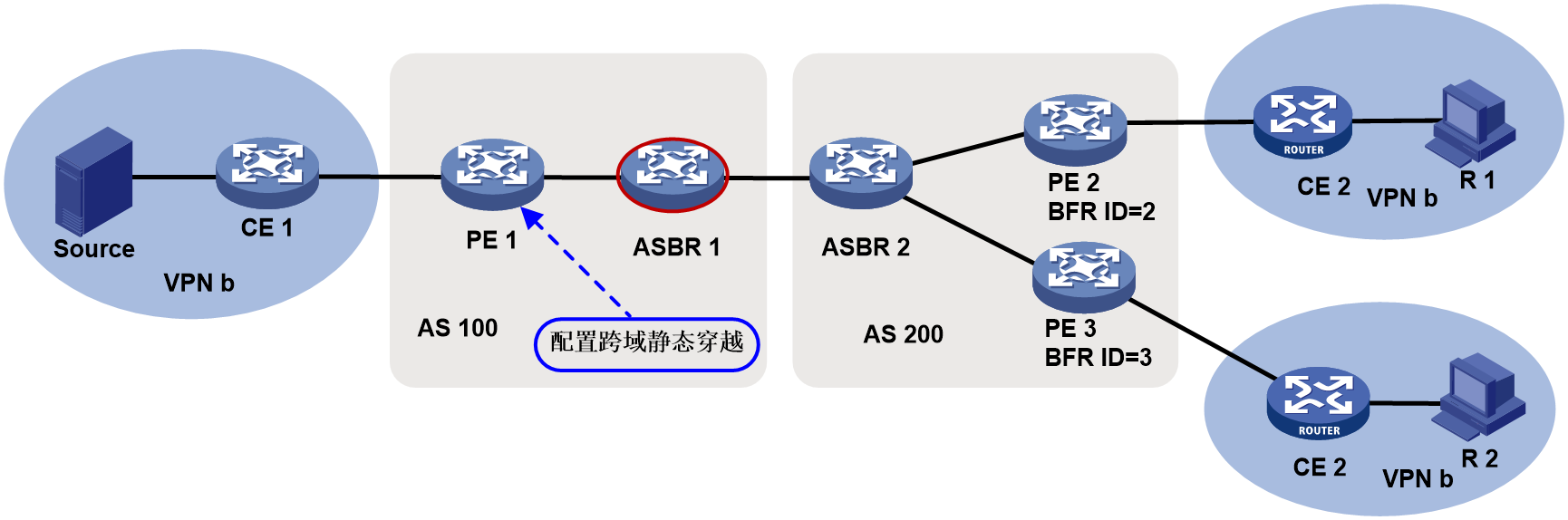
In a cross-AS BIER deployment, if the ASBR in an AS does not support BIER forwarding, BIER packets cannot be forwarded among ASs. To solve this problem, you can specify the BFR neighbor on the BFR directly connected to the ASBR and the BFR ID range of BIER edge devices that can be reached through the BFR neighbor.
Figure 6 Static cross-AS BIER
Restrictions and guidelines
In the same BIER sub-domain, the BFR ID ranges for different BFR neighbors cannot be overlapping. The configuration performed later does not take effect.
The configuration takes effect only on the BIRT of the local node and will not be advertised to other nodes.
The total number of BFR neighbors in all BIER sub-domains on the device cannot exceed 2000. The number of BFR IDs reachable through one BFR neighbor cannot exceed 256.
You can specify a maximum number of four BFR neighbors with the same link priority for reaching a BFR ID.
Procedure
1. Enter system view.
system-view
2. Enter BIER view.
bier
3. Enter sub-domain view.
sub-domain sub-domain-id ipv6
4. Specify a BFR neighbor and the BFR ID range of BIER edge devices that can be reached through the BFR neighbor.
bfr-neighbor mpra ipv6-address bfr-id bfr-id-start [ to bfr-id-end ] [ preference preference-value ]
By default, no BFR neighbor and BFR ID range are specified.
Configuring BGP-based cross-AS BIER
Enabling BIER for BGP
About this task
If BIER is enabled for BGP, BGP imports the BFR IDs and BFR prefixes from the BIER module and generates BGP routes carrying BIER information (excluding BFR ID range information).
The device generates a BGP IPv6 unicast route without BIER information and advertises the route to the BGP IPv6 unicast peers. The BGP IPv6 unicast route uses the locally configured MPRA and BFR prefix as the reachability prefix information of the NLRI field. The BGP IPv6 unicast route can guide the forwarding of BIER packets on devices that do not support BIER forwarding. If the peer capability bier command is also executed, the BGP routes generated by the local BFR prefix carry BIER path attributes can be advertised to the specified peer or peer group.
Restrictions and guidelines
You must perform this task before performing the following tasks:
· Enable the device to exchange routes with BIER path attributes with a peer or peer group.
· Enable BGP BFR prefix proxying.
· Enable BGP to redistribute routes from an IGP.
For more information about configuring BGP instances and address families, see BGP in Layer 3—IP Services Configuration Guide and Layer 3—IP Services Command Reference.
Procedure
1. Enter system view.
system-view
2. Enter BIER view.
bier
3. Enter sub-domain view.
sub-domain sub-domain-id ipv6
4. Configure the encapsulation type, BSL, and maximum SI.
encapsulation-type g-bier bsl bsl-value max-si max-si-value
By default, the encapsulation type, BSL, and maximum SI are not configured.
Enabling the device to exchange routes with BIER path attributes with a peer or peer group
About this task
With this feature configured, BGP will advertise received BIER information to the BIER module for it to generate a BIRT.
The device cannot exchange routes with BIER path attributes with peers or peer groups other than the specified peer or peer group.
Preprequisites
Before performing this task, you must enable BIER for BGP.
Procedure
1. Enter system view.
system-view
2. Enter BGP instance view.
bgp as-number [ instance instance-name ]
3. Enter BGP IPv6 unicast address family view.
address-family ipv6 [ unicast ]
4. Enable BGP to exchange routes with BIER path attributes with a peer or peer group.
peer { group-name | ipv4-address [ mask-length ] | ipv6-address [ prefix-length ] } capability bier
By default, the device cannot exchange routes with BIER path attributes with any peers or peer groups.
Enabling BGP BFR prefix proxying
Restrictions and guidelines
To avoid loops and ensure correct BIRT entries, perform this task only on one end of an EBGP session.
Preprequisites
Before performing this task, you must enable BIER for BGP.
Procedure
1. Enter system view.
system-view
2. Enter BGP instance view.
bgp as-number [ instance instance-name ]
3. Enter BGP IPv6 unicast address family view.
address-family ipv6 [ unicast ]
4. Enable BGP BFR prefix proxying.
bier bfr-prefix proxy
By default, BGP BFR prefix proxying is disabled.
Enabling BGP to redistribute the BIER information from an IGP
About this task
Perform this task to redistribute the BIER information from an IGP to the BGP routing table for distribution.
Restrictions and guidelines
The redistributed BIER information includes the BFR ID range information. The following rules apply to the inclusion of BFR ID range information when BGP routes generated based on the BIER information are advertised:
· If BGP BFR prefix proxying is not enabled:
¡ The BFR ID range information is not included when BGP routes are advertised to an IBGP peer.
¡ The BFR ID range information is included when BGP routes are advertised to an EBGP peer.
· If BGP BFR prefix proxying is enabled, the BFR ID range information is included when BGP routes are advertised to either an EBGP peer or an IBGP peer.
Preprequisites
Before performing this task, you must enable BIER for BGP.
Procedure
1. Enter system view.
system-view
2. Enter BGP instance view.
bgp as-number [ instance instance-name ]
3. Enter BGP IPv6 unicast address family view.
address-family ipv6 [ unicast ]
4. Enable BGP to redistribute the BIER information from an IGP.
import-bier isisv6 { process-id | all-processes }
By default, BGP does not redistribute the BIER information from an IGP.
After you redistribute the BIER information from all processes of a routing protocol by using the all-processes keyword, this command does not take effect on any processes of the protocol.
Display and maintenance commands for BIER
Execute the display commands in any view and the reset commands in user view.
|
Task |
Command |
|
Display BFR prefix information. |
display bier prefix [ prefix-ip ] [ sub-domain sub-domain-id [ bsl bsl-value ] ] |
|
Display BIER routing table information. |
display bier routing-table [ sub-domain sub-domain-id [ bsl bsl-value ] ] [ prefix prefix-ip ] [ verbose ] |
|
Display BIER sub-domain information. |
display bier sub-domain [ sub-domain-id ] |
|
Display the IGP that registered with BIER. |
display bier protocol |
|
Display BIER packet statistics. |
display bier forward ipv6 statistics slot slot-number |
|
Clear BIER packet statistics. |
reset bier forward ipv6 statistics [ slot slot-number ] |
BIER configuration examples
Example: Configuring intra-AS BIER-based MVPN
Network configuration
As shown in Figure 7, configure intra-AS BIER-based MVPN to meet the following requirements:
|
Item |
Network configuration |
|
Multicast sources and receivers |
· In VPN instance a, S 1 is a multicast source, and R 1, R 2, and R 3 are receivers. · In VPN instance b, S 2 is a multicast source, and R 4 is a receiver. |
|
VPN instances to which PE interfaces belong |
· PE 1: Ten-GigabitEthernet 3/0/2 and Ten-GigabitEthernet 3/0/3 belong to VPN instance a. Ten-GigabitEthernet 3/0/1 and Loopback 1 belong to the public network. · PE 2: Ten-GigabitEthernet 3/0/2 belongs to VPN instance b. Ten-GigabitEthernet 3/0/3 belongs to VPN instance a. Ten-GigabitEthernet 3/0/1 and Loopback 1 belong to the public network. · PE 3: Ten-GigabitEthernet 3/0/2 belongs to VPN instance a. Ten-GigabitEthernet 3/0/3 and Loopback 2 belong to VPN instance b. Ten-GigabitEthernet 3/0/1 and Loopback 1 belong to the public network. |
|
Unicast routing protocols and BIER |
· Configure IS-IS on the public network, and configure RIP between the PEs and the CEs. · Establish BGP peer connections between PE 1, PE 2, and PE 3 on their respective Loopback 1. · Configure BIER on the public network. |
|
IP multicast routing |
· Enable IP multicast routing for VPN instance a on PE 1, PE 2, and PE 3. · Enable IP multicast routing for VPN instance b on PE 2 and PE 3. · Enable IP multicast routing on CE a1, CE a2, CE a3, CE b1, and CE b2. |
|
IGMP |
· Enable IGMPv2 on Ten-GigabitEthernet 3/0/2 of PE 1. · Enable IGMPv2 on Ten-GigabitEthernet 3/0/1 of CE a2, CE a3, and CE b2. |
|
PIM |
· Enable PIM-SM on all interfaces that do not have attached receiver hosts on PE 1, PE 2, and PE 3. · Enable PIM-SM on all interfaces that do not have attached receiver hosts on CE a1, CE a2, CE a3, CE b1, and CE b2. · Configure Loopback 1 of CE a2 as a C-BSR and a C-RP for VPN instance a to provide services for all multicast groups. · Configure Loopback 2 of PE 3 as a C-BSR and a C-RP for VPN instance b to provide services for all multicast groups. |
|
MSDP |
· Enable MSDP on CE a2, and specify Ten-GigabitEthernet 3/0/2 as the local MSDP connection interface. · Enable MSDP on PE 2 for VPN instance a, and specify Ten-GigabitEthernet 3/0/3 as the local MSDP connection interface. |
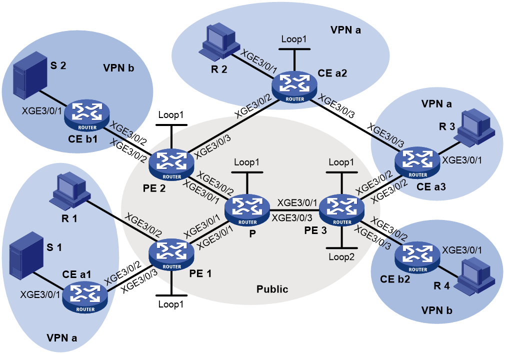
Table 1 Interface and IP address assignment
|
Device |
Interface |
IP address |
Device |
Interface |
IP address |
|
S 1 |
— |
10.110.7.2/24 |
PE 3 |
XGE3/0/1 |
192.168.8.1/24 |
|
S 2 |
— |
10.110.8.2/24 |
PE 3 |
XGE3/0/2 |
10.110.5.1/24 |
|
R 1 |
— |
10.110.1.2/24 |
PE 3 |
XGE3/0/3 |
10.110.6.1/24 |
|
R 2 |
— |
10.110.9.2/24 |
PE 3 |
Loop1 |
1.1.1.3/32 |
|
R 3 |
— |
10.110.10.2/24 |
PE 3 |
Loop2 |
33.33.33.33/32 |
|
R 4 |
— |
10.110.11.2/24 |
CE a1 |
XGE3/0/1 |
10.110.7.1/24 |
|
P |
XGE3/0/1 |
192.168.6.2/24 |
CE a1 |
XGE3/0/2 |
10.110.2.2/24 |
|
P |
XGE3/0/2 |
192.168.7.2/24 |
CE a2 |
XGE3/0/1 |
10.110.9.1/24 |
|
P |
XGE3/0/3 |
192.168.8.2/24 |
CE a2 |
XGE3/0/2 |
10.110.4.2/24 |
|
P |
Loop1 |
2.2.2.2/32 |
CE a2 |
XGE3/0/3 |
10.110.12.1/24 |
|
PE 1 |
XGE3/0/1 |
192.168.6.1/24 |
CE a2 |
Loop1 |
22.22.22.22/32 |
|
PE 1 |
XGE3/0/2 |
10.110.1.1/24 |
CE a3 |
XGE3/0/1 |
10.110.10.1/24 |
|
PE 1 |
XGE3/0/3 |
10.110.2.1/24 |
CE a3 |
XGE3/0/2 |
10.110.5.2/24 |
|
PE 1 |
Loop1 |
1.1.1.1/32 |
CE a3 |
XGE3/0/3 |
10.110.12.2/24 |
|
PE 2 |
XGE3/0/1 |
192.168.7.1/24 |
CE b1 |
XGE3/0/1 |
10.110.8.1/24 |
|
PE 2 |
XGE3/0/2 |
10.110.3.1/24 |
CE b1 |
XGE3/0/2 |
10.110.3.2/24 |
|
PE 2 |
XGE3/0/3 |
10.110.4.1/24 |
CE b2 |
XGE3/0/1 |
10.110.11.1/24 |
|
PE 2 |
Loop1 |
1.1.1.2/32 |
CE b2 |
XGE3/0/2 |
10.110.6.2/24 |
Procedure
1. Configure PE 1:
# Configure a global router ID.
<PE1> system-view
[PE1] router id 1.1.1.1
# Assign PE 1 to sub-domain 0, configure the BFR ID as 1, and configure the BFR prefix as the IPv6 address of Loopback 1.
[PE1] bier
[PE1-bier] sub-domain 0 ipv6
[PE1-bier-sub-domain-0-ipv6] bfr-id 1
[PE1-bier-sub-domain-0-ipv6] bfr-prefix interface LoopBack1
# Configure BIER with the G-BIER encapsulation.
[PE1-bier-sub-domain-0-ipv6] encapsulation-type g-bier bsl 128 max-si 32
# Configure 5001::1 as the multicast policy reserved address.
[PE1-bier-sub-domain-0-ipv6] g-bier mpra 5001::1
# Configure SRv6.
[PE1] segment-routing ipv6
[PE1-segment-routing-ipv6] encapsulation source-address 11::11
[PE1-segment-routing-ipv6] locator aaa ipv6-prefix 1:2:: 96 static 8
# Configure a multicast service prefix.
[PE1] multicast-service-prefix ms1 ipv6-prefix 1234:1:: 64 service-id-length 10
# Configure SRv6.
[PE1] segment-routing ipv6
[PE1-segment-routing-ipv6] encapsulation source-address 11::11
[PE1-segment-routing-ipv6] locator aaa ipv6-prefix 1:2:: 96 static 8
# Create a VPN instance named a, and configure an RD and route targets for the VPN instance.
[PE1] ip vpn-instance a
[PE1-vpn-instance-a] route-distinguisher 100:1
[PE1-vpn-instance-a] vpn-target 100:1 export-extcommunity
[PE1-vpn-instance-a] vpn-target 100:1 import-extcommunity
[PE1-vpn-instance-a] quit
# Enable IP multicast routing in VPN instance a.
[PE1] multicast routing vpn-instance a
[PE1-mrib-a] quit
# Create a BIER-based MVPN for VPN instance a.
[PE1] multicast-vpn vpn-instance a mode bier
# Create an MVPN IPv4 address family for VPN instance a.
[PE1-mvpn-a] address-family ipv4
# Specify the MVPN source interface for VPN instance a.
[PE1-mvpn-a-ipv4] source loopback 1
# Enable dynamic inclusive tunnel creation and dynamic selective tunnel creation for VPN instance a.
[PE1-mvpn-a-ipv4] inclusive-tunnel dynamic sub-domain 0 bsl 128
[PE1-mvpn-a-ipv4] selective-tunnel dynamic sub-domain 0 bsl 128
[PE1-mvpn-a-ipv4] tunnel-source multicast-service-prefix ms1 service-id 12
[PE1-mvpn-a-ipv4] quit
[PE1-mvpn-a] quit
# Assign an IP address to Ten-GigabitEthernet 3/0/1, and enable IS-IS on Ten-GigabitEthernet 3/0/1.
[PE1] interface ten-gigabitethernet 3/0/1
[PE1-Ten-GigabitEthernet3/0/1] ipv6 address 9000:6::1 64
[PE1-Ten-GigabitEthernet3/0/1] isis ipv6 enable 1
[PE1-Ten-GigabitEthernet3/0/1] quit
# Associate Ten-GigabitEthernet 3/0/2 with VPN instance a, assign an IP address to the interface, and enable IGMP on the interface.
[PE1] interface ten-gigabitethernet 3/0/2
[PE1-Ten-GigabitEthernet3/0/2] ip binding vpn-instance a
[PE1-Ten-GigabitEthernet3/0/2] ip address 10.110.1.1 24
[PE1-Ten-GigabitEthernet3/0/2] igmp enable
[PE1-Ten-GigabitEthernet3/0/2] quit
# Associate Ten-GigabitEthernet 3/0/3 with VPN instance a, assign an IP address to the interface, and enable PIM-SM on the interface.
[PE1] interface ten-gigabitethernet 3/0/3
[PE1-Ten-GigabitEthernet3/0/3] ip binding vpn-instance a
[PE1-Ten-GigabitEthernet3/0/3] ip address 10.110.2.1 24
[PE1-Ten-GigabitEthernet3/0/3] pim sm
[PE1-Ten-GigabitEthernet3/0/3] quit
# Assign an IP address to Loopback 1, and enable IS-IS on the interface.
[PE1] interface loopback 1
[PE1-LoopBack1] ip address 1.1.1.1 32
[PE1-LoopBack1] ipv6 address 1111::1111 128
[PE1-LoopBack1] isis ipv6 enable 1
[PE1-LoopBack1] quit
# Configure BGP.
[PE1] bgp 100
[PE1-bgp-default] peer 1112::1112 as-number 100
[PE1-bgp-default] peer 1112::1112 connect-interface loopback 1
[PE1-bgp-default] peer 1113::1113 as-number 100
[PE1-bgp-default] peer 1113::1113 connect-interface loopback 1
[PE1-bgp-default] address-family ipv4 mvpn
[PE1-bgp-default-mvpn] peer 1112::1112 enable
[PE1-bgp-default-mvpn] peer 1113::1113 enable
[PE1-bgp-default-mvpn] quit
[PE1-bgp-default] address-family vpnv4
[PE1-bgp-default-vpnv4] mvpn-advertise-rt-import
[PE1-bgp-default-vpnv4] peer 1112::1112 enable
[PE1-bgp-default-vpnv4] peer 1113::1113 enable
[PE1-bgp-default-vpnv4] peer 1112::1112 prefix-sid
[PE1-bgp-default-vpnv4] peer 1113::1113 prefix-sid
[PE1-bgp-default-vpnv4] quit
[PE1–bgp-default] ip vpn-instance a
[PE1-bgp-default-a] address-family ipv4 unicast
[PE1-bgp-default-ipv4-a] import-route rip 2
[PE1-bgp-default-ipv4-a] import-route direct
[PE1-bgp-default-ipv4-a] segment-routing ipv6 best-effort
[PE1-bgp-default-ipv4-a] segment-routing ipv6 locator aaa
[PE1-bgp-default-ipv4-a] quit
[PE1-bgp-default-a] quit
[PE1–bgp-default] quit
# Configure IS-IS.
[PE1] isis 1
[PE1-isis-1] is-level level-1
[PE1-isis-1] cost-style wide
[PE1-isis-1] bier enable
[PE1-isis-1] network-entity 10.0000.0000.0001.00
[PE1-isis-1] address-family ipv6 unicast
[PE1-isis-1-ipv6] segment-routing ipv6 locator aaa
# Configure RIP.
[PE1] rip 2 vpn-instance a
[PE1-rip-2] network 10.110.1.0 0.0.0.255
[PE1-rip-2] network 10.110.2.0 0.0.0.255
[PE1-rip-2] import-route bgp
[PE1-rip-2] quit
2. Configure PE 2:
# Configure a global router ID.
<PE2> system-view
[PE2] router id 1.1.1.2
# Assign PE 2 to sub-domain 0, configure the BFR ID as 2, and configure the BFR prefix as the IPv6 address of Loopback 1.
[PE2] bier
[PE2-bier] sub-domain 0 ipv6
[PE2-bier-sub-domain-0-ipv6] bfr-id 2
[PE2-bier-sub-domain-0-ipv6] bfr-prefix interface LoopBack1
# Configure BIER with the G-BIER encapsulation.
[PE2-bier-sub-domain-0-ipv6] encapsulation-type g-bier bsl 128 max-si 32
# Configure 5002::1 as the multicast policy reserved address.
[PE2-bier-sub-domain-0-ipv6] g-bier mpra 5002::1
# Configure SRv6.
[PE2] segment-routing ipv6
[PE2-segment-routing-ipv6] encapsulation source-address 22::22
[PE2-segment-routing-ipv6] locator aaa ipv6-prefix 2:2:: 96 static 8
# Configure a multicast service prefix.
[PE2] multicast-service-prefix ms1 ipv6-prefix 1234:2:: 64 service-id-length 10
# Create a VPN instance named b, and configure an RD and route targets for the VPN instance.
[PE2] ip vpn-instance b
[PE2-vpn-instance-b] route-distinguisher 200:1
[PE2-vpn-instance-b] vpn-target 200:1 export-extcommunity
[PE2-vpn-instance-b] vpn-target 200:1 import-extcommunity
[PE2-vpn-instance-b] quit
# Enable IP multicast routing for VPN instance b.
[PE2] multicast routing vpn-instance b
[PE2-mrib-b] quit
# Create a BIER-based MVPN for VPN instance b.
[PE2] multicast-vpn vpn-instance b mode bier
# Create an MVPN IPv4 address family for VPN instance b.
[PE2-mvpn-b] address-family ipv4
# Specify the MVPN source interface for VPN instance b.
[PE2-mvpn-b-ipv4] source loopback 1
# Enable dynamic inclusive tunnel creation and dynamic selective tunnel creation for VPN instance b.
[PE2-mvpn-b-ipv4] inclusive-tunnel dynamic sub-domain 0 bsl 128
[PE2-mvpn-b-ipv4] selective-tunnel dynamic sub-domain 0 bsl 128
[PE2-mvpn-b-ipv4] tunnel-source multicast-service-prefix ms1 service-id 12
[PE2-mvpn-b-ipv4] quit
[PE2-mvpn-b] quit
# Create a VPN instance named a, and configure an RD and route targets for the VPN instance.
[PE2] ip vpn-instance a
[PE2-vpn-instance-a] route-distinguisher 100:1
[PE2-vpn-instance-a] vpn-target 100:1 export-extcommunity
[PE2-vpn-instance-a] vpn-target 100:1 import-extcommunity
[PE2-vpn-instance-a] quit
# Enable IP multicast routing for VPN instance a.
[PE2] multicast routing vpn-instance a
[PE2-mrib-a] quit
# Create a BIER-based MVPN for VPN instance a.
[PE2] multicast-vpn vpn-instance a mode bier
# Create an MVPN IPv4 address family for VPN instance a.
[PE2-mvpn-a] address-family ipv4
# Specify the MVPN source interface for VPN instance a.
[PE2-mvpn-a-ipv4] source loopback 1
[PE2-mvpn-a-ipv4] quit
[PE2-mvpn-a] quit
# Assign an IP address to Ten-GigabitEthernet 3/0/1, and enable IS-IS on the interface.
[PE2] interface ten-gigabitethernet 3/0/1
[PE2-Ten-GigabitEthernet3/0/1] ipv6 address 9000:7::1 64
[PE2-Ten-GigabitEthernet3/0/1] isis ipv6 enable 1
[PE2-Ten-GigabitEthernet3/0/1] quit
# Associate Ten-GigabitEthernet 3/0/2 with VPN instance b, assign an IP address to the interface, and enable PIM-SM on the interface.
[PE2] interface ten-gigabitethernet 3/0/2
[PE2-Ten-GigabitEthernet3/0/2] ip binding vpn-instance b
[PE2-Ten-GigabitEthernet3/0/2] ip address 10.110.3.1 24
[PE2-Ten-GigabitEthernet3/0/2] pim sm
[PE2-Ten-GigabitEthernet3/0/2] quit
# Associate Ten-GigabitEthernet 3/0/3 with VPN instance a, assign an IP address to the interface, and enable PIM-SM on the interface.
[PE2] interface ten-gigabitethernet 3/0/3
[PE2-Ten-GigabitEthernet3/0/3] ip binding vpn-instance a
[PE2-Ten-GigabitEthernet3/0/3] ip address 10.110.4.1 24
[PE2-Ten-GigabitEthernet3/0/3] pim sm
[PE2-Ten-GigabitEthernet3/0/3] quit
# Assign an IP address to Loopback 1 and enable IS-IS on the interface.
[PE2] interface loopback 1
[PE2-LoopBack1] ip address 1.1.1.2 32
[PE2-LoopBack1] ipv6 address 1112::1112 128
[PE2-LoopBack1] isis ipv6 enable 1
[PE2-LoopBack1] quit
# Configure BGP.
[PE2] bgp 100
[PE2-bgp-default] peer 1111::1111 as-number 100
[PE2-bgp-default] peer 1111::1111 connect-interface loopback 1
[PE2-bgp-default] peer 1113::1113 as-number 100
[PE2-bgp-default] peer 1113::1113 connect-interface loopback 1
[PE2-bgp-default] address-family ipv4 mvpn
[PE2-bgp-default-mvpn] peer 1111::1111 enable
[PE2-bgp-default-mvpn] peer 1113::1113 enable
[PE2-bgp-default-mvpn] quit
[PE2-bgp-default] address-family vpnv4
[PE2-bgp-default-vpnv4] mvpn-advertise-rt-import
[PE2-bgp-default-vpnv4] peer 1111::1111 enable
[PE2-bgp-default-vpnv4] peer 1113::1113 enable
[PE2-bgp-default-vpnv4] peer 1111::1111 prefix-sid
[PE2-bgp-default-vpnv4] peer 1113::1113 prefix-sid
[PE2-bgp-default-vpnv4] quit
[PE2–bgp-default] ip vpn-instance a
[PE2-bgp-default-a] address-family ipv4 unicast
[PE2-bgp-default-ipv4-a] import-route rip 2
[PE2-bgp-default-ipv4-a] import-route direct
[PE2-bgp-default-ipv4-a] segment-routing ipv6 best-effort
[PE2-bgp-default-ipv4-a] segment-routing ipv6 locator aaa
[PE2-bgp-default-ipv4-a] quit
[PE2-bgp-default-a] quit
[PE2–bgp-default] ip vpn-instance b
[PE2-bgp-default-b] address-family ipv4 unicast
[PE2-bgp-default-ipv4-b] import-route rip 3
[PE2-bgp-default-ipv4-b] import-route direct
[PE2-bgp-default-ipv4-b] segment-routing ipv6 best-effort
[PE2-bgp-default-ipv4-b] segment-routing ipv6 locator aaa
[PE2-bgp-default-ipv4-b] quit
[PE2-bgp-default-b] quit
[PE2–bgp-default] quit
# Configure IS-IS.
[PE2] isis 1
[PE2-isis-1] is-level level-1
[PE2-isis-1] cost-style wide
[PE2-isis-1] bier enable
[PE2-isis-1] network-entity 10.0000.0000.0002.00
[PE2-isis-1] address-family ipv6 unicast
[PE2-isis-1-ipv6] segment-routing ipv6 locator aaa
# Configure RIP.
[PE2] rip 2 vpn-instance a
[PE2-rip-2] network 10.110.4.0 0.0.0.255
[PE2-rip-2] import-route bgp
[PE2-rip-2] quit
[PE2] rip 3 vpn-instance b
[PE2-rip-3] network 10.110.3.0 0.0.0.255
[PE2-rip-3] import-route bgp
[PE2-rip-3] quit
3. Configure PE 3:
# Configure a global router ID.
<PE3> system-view
[PE3] router id 1.1.1.3
# Assign PE 3 to sub-domain 0, configure the BFR ID as 3, and configure the BFR prefix as the IPv6 address of Loopback 1.
[PE3] bier
[PE3-bier] sub-domain 0 ipv6
[PE3-bier-sub-domain-0-ipv6] bfr-id 1
[PE3-bier-sub-domain-0-ipv6] bfr-prefix interface LoopBack1
# Configure BIER with the G-BIER encapsulation.
[PE3-bier-sub-domain-0-ipv6] encapsulation-type g-bier bsl 128 max-si 32
# Configure 5003::1 as the multicast policy reserved address.
[PE3-bier-sub-domain-0-ipv6] g-bier mpra 5003::1
# Configure SRv6.
[PE3] segment-routing ipv6
[PE3-segment-routing-ipv6] encapsulation source-address 33::33
[PE3-segment-routing-ipv6] locator aaa ipv6-prefix 3:2:: 96 static 8
# Configure a multicast service prefix.
[PE3] multicast-service-prefix ms1 ipv6-prefix 1234:3:: 64 service-id-length 10
# Create a VPN instance named a, and configure an RD and route targets for the VPN instance.
[PE3] ip vpn-instance a
[PE3-vpn-instance-a] route-distinguisher 100:1
[PE3-vpn-instance-a] vpn-target 100:1 export-extcommunity
[PE3-vpn-instance-a] vpn-target 100:1 import-extcommunity
[PE3-vpn-instance-a] quit
# Enable IP multicast routing for VPN instance a.
[PE3] multicast routing vpn-instance a
[PE3-mrib-a] quit
# Create a BIER-based MVPN for VPN instance a.
[PE3] multicast-vpn vpn-instance a mode bier
# Create an MVPN IPv4 address family for VPN instance a.
[PE3-mvpn-a] address-family ipv4
# Specify the MVPN source interface for VPN instance a.
[PE3-mvpn-a-ipv4] source loopback 1
[PE3-mvpn-a-ipv4] quit
[PE3-mvpn-a] quit
# Create a VPN instance named b, and configure an RD and route targets for the VPN instance.
[PE3] ip vpn-instance b
[PE3-vpn-instance-b] route-distinguisher 200:1
[PE3-vpn-instance-b] vpn-target 200:1 export-extcommunity
[PE3-vpn-instance-b] vpn-target 200:1 import-extcommunity
[PE3-vpn-instance-b] quit
# Enable IP multicast routing for VPN instance b.
[PE3] multicast routing vpn-instance b
[PE3-mrib-b] quit
# Create a BIER-based MVPN for VPN instance b.
[PE3] multicast-vpn vpn-instance b mode bier
# Create an MVPN IPv4 address family for VPN instance b.
[PE3-mvpn-b] address-family ipv4
# Specify the MVPN source interface for VPN instance b.
[PE3-mvpn-b-ipv4] source loopback 1
[PE3-mvpn-b-ipv4] quit
[PE3-mvpn-b] quit
# Assign an IP address to Ten-GigabitEthernet 3/0/1, and enable IS-IS on the interface.
[PE3] interface ten-gigabitethernet 3/0/1
[PE3-Ten-GigabitEthernet3/0/1] ipv6 address 9000:8::1 64
[PE3-Ten-GigabitEthernet3/0/1] isis ipv6 enable 1
[PE3-Ten-GigabitEthernet3/0/1] quit
# Associate Ten-GigabitEthernet 3/0/2 with VPN instance a, assign an IP address to the interface, and enable PIM-SM on the interface.
[PE3] interface ten-gigabitethernet 3/0/2
[PE3-Ten-GigabitEthernet3/0/2] ip binding vpn-instance a
[PE3-Ten-GigabitEthernet3/0/2] ip address 10.110.5.1 24
[PE3-Ten-GigabitEthernet3/0/2] pim sm
[PE3-Ten-GigabitEthernet3/0/2] quit
# Associate Ten-GigabitEthernet 3/0/3 with VPN instance b, assign an IP address to the interface, and enable PIM-SM on the interface.
[PE3] interface ten-gigabitethernet 3/0/3
[PE3-Ten-GigabitEthernet3/0/3] ip binding vpn-instance b
[PE3-Ten-GigabitEthernet3/0/3] ip address 10.110.6.1 24
[PE3-Ten-GigabitEthernet3/0/3] pim sm
[PE3-Ten-GigabitEthernet3/0/3] quit
# Assign an IP address to Loopback 1 and enable IS-IS on the interface.
[PE3] interface loopback 1
[PE3-LoopBack1] ip address 1.1.1.3 32
[PE3-LoopBack1] ipv6 address 1113::1113 128
[PE3-LoopBack1] isis ipv6 enable 1
[PE3-LoopBack1] quit
# Associate Loopback 2 with VPN instance b, assign an IP address to the interface, and enable PIM-SM on the interface.
[PE3] interface loopback 2
[PE3-LoopBack2] ip binding vpn-instance b
[PE3-LoopBack2] ip address 33.33.33.33 32
[PE3-LoopBack2] pim sm
[PE3-LoopBack2] quit
# Configure Loopback 2 as a C-BSR and a C-RP.
[PE3] pim vpn-instance b
[PE3-pim-b] c-bsr 33.33.33.33
[PE3-pim-b] c-rp 33.33.33.33
[PE3-pim-b] quit
# Configure BGP.
[PE3] bgp 100
[PE3-bgp-default] peer 1111::1111 as-number 100
[PE3-bgp-default] peer 1111::1111 connect-interface loopback 1
[PE3-bgp-default] peer 1112::1112 as-number 100
[PE3-bgp-default] peer 1112::1112 connect-interface loopback 1
[PE3-bgp-default] address-family ipv4 mvpn
[PE3-bgp-default-mvpn] peer 1111::1111 enable
[PE3-bgp-default-mvpn] peer 1112::1112 enable
[PE3-bgp-default-mvpn]quit
[PE3-bgp-default] address-family vpnv4
[PE3-bgp-default-vpnv4] mvpn-advertise-rt-import
[PE3-bgp-default-vpnv4] peer 1111::1111 enable
[PE3-bgp-default-vpnv4] peer 1112::1112 enable
[PE3-bgp-default-vpnv4] peer 1111::1111 prefix-sid
[PE3-bgp-default-vpnv4] peer 1112::1112 prefix-sid
[PE3-bgp-default-vpnv4] quit
[PE3–bgp-default] ip vpn-instance a
[PE3-bgp-default-a] address-family ipv4 unicast
[PE3-bgp-default-ipv4-a] import-route rip 2
[PE3-bgp-default-ipv4-a] import-route direct
[PE3-bgp-default-ipv4-a] segment-routing ipv6 best-effort
[PE3-bgp-default-ipv4-a] segment-routing ipv6 locator aaa
[PE3-bgp-default-ipv4-a] quit
[PE3-bgp-default-a] quit
[PE3–bgp-default] ip vpn-instance b
[PE3-bgp-default-b] address-family ipv4 unicast
[PE3-bgp-default-ipv4-b] import-route rip 3
[PE3-bgp-default-ipv4-b] import-route direct
[PE3-bgp-default-ipv4-b] segment-routing ipv6 best-effort
[PE3-bgp-default-ipv4-b] segment-routing ipv6 locator aaa
[PE3-bgp-default-ipv4-b] quit
[PE3-bgp-default-b] quit
[PE3–bgp-default] quit
# Configure IS-IS.
[PE3] isis 1
[PE3-isis-1] is-level level-1
[PE3-isis-1] cost-style wide
[PE3-isis-1] bier enable
[PE3-isis-1] network-entity 10.0000.0000.0003.00
[PE3-isis-1] address-family ipv6 unicast
[PE3-isis-1-ipv6] segment-routing ipv6 locator aaa
# Configure RIP.
[PE3] rip 2 vpn-instance a
[PE3-rip-2] network 10.110.5.0 0.0.0.255
[PE3-rip-2] import-route bgp
[PE3-rip-2] quit
[PE3] rip 3 vpn-instance b
[PE3-rip-3] network 10.110.6.0 0.0.0.255
[PE3-rip-3] network 33.33.33.33 0.0.0.0
[PE3-rip-3] import-route bgp
[PE3-rip-3] quit
4. Configure P:
# Assign P to sub-domain 0, configure the BFR ID as 4, and configure the BFR prefix as the IPv6 address of Loopback 1.
[P] bier
[P-bier] sub-domain 0 ipv6
[P-bier-sub-domain-0-ipv6] bfr-id 4
[P-bier-sub-domain-0-ipv6] bfr-prefix interface LoopBack1
# Configure BIER with the G-BIER encapsulation.
[P-bier-sub-domain-0-ipv6] encapsulation-type g-bier bsl 128 max-si 32
# Configure 5004::1 as the multicast policy reserved address.
[P-bier-sub-domain-0-ipv6] g-bier mpra 5004::1
# Configure SRv6.
[P] segment-routing ipv6
[P-segment-routing-ipv6] encapsulation source-address 44::44
[P-segment-routing-ipv6] locator aaa ipv6-prefix 4:2:: 96 static 8
# Assign an IP address to Ten-GigabitEthernet 3/0/1, and enable IS-IS on the interface.
[P] interface ten-gigabitethernet 3/0/1
[P-Ten-GigabitEthernet3/0/1] ipv6 address 9000:6::2 64
[P-Ten-GigabitEthernet3/0/1] isis ipv6 enable 1
[P-Ten-GigabitEthernet3/0/1] quit
# Assign an IP address to Ten-GigabitEthernet 3/0/2, and enable IS-IS on the interface.
[P] interface ten-gigabitethernet 3/0/2
[P-Ten-GigabitEthernet3/0/2] ipv6 address 9000:7::2 64
[P-Ten-GigabitEthernet3/0/2] isis ipv6 enable 1
[P-Ten-GigabitEthernet3/0/2] quit
# Assign an IP address to Ten-GigabitEthernet3/0/3, and enable IS-IS on the interface.
[P] interface ten-gigabitethernet 3/0/3
[P-Ten-GigabitEthernet3/0/3] ipv6 address 9000:8::2 64
[P-Ten-GigabitEthernet3/0/2] isis ipv6 enable 1
[P-Ten-GigabitEthernet3/0/3] quit
# Assign an IP address to Loopback 1 and enable IS-IS on the interface.
[P] interface loopback 1
[P-LoopBack1] ip address 2.2.2.2 32
[P-LoopBack1] ipv6 address 2222::2222 64
[P-LoopBack1] isis ipv6 enable 1
[P-LoopBack1] quit
# Configure IS-IS.
[P] isis 1
[P-isis-1] is-level level-1
[P-isis-1] cost-style wide
[P-isis-1] bier enable
[P-isis-1] network-entity 10.0000.0000.0004.00
[P-isis-1] address-family ipv6 unicast
[P-isis-1-ipv6] segment-routing ipv6 locator aaa
[P-isis-1-ipv6] quit
[P-isis-1] quit
5. Configure CE a1:
# Enable IP multicast routing.
<CEa1> system-view
[CEa1] multicast routing
[CEa1-mrib] quit
# Assign an IP address to Ten-GigabitEthernet 3/0/1, and enable PIM-SM on the interface.
[CEa1] interface ten-gigabitethernet 3/0/1
[CEa1-Ten-GigabitEthernet3/0/1] ip address 10.110.7.1 24
[CEa1-Ten-GigabitEthernet3/0/1] pim sm
[CEa1-Ten-GigabitEthernet3/0/1] quit
# Assign an IP address to Ten-GigabitEthernet 3/0/2, and enable PIM-SM on the interface.
[CEa1] interface ten-gigabitethernet 3/0/2
[CEa1-Ten-GigabitEthernet3/0/2] ip address 10.110.2.2 24
[CEa1-Ten-GigabitEthernet3/0/2] pim sm
[CEa1-Ten-GigabitEthernet3/0/2] quit
# Configure RIP.
[CEa1] rip 2
[CEa1-rip-2] network 10.110.2.0 0.0.0.255
[CEa1-rip-2] network 10.110.7.0 0.0.0.255
[CEa1-rip-2] quit
6. Configure CE b1:
# Enable IP multicast routing.
<CEb1> system-view
[CEb1] multicast routing
[CEb1-mrib] quit
# Assign an IP address to Ten-GigabitEthernet 3/0/1, and enable PIM-SM on the interface.
[CEb1] interface ten-gigabitethernet 3/0/1
[CEb1-Ten-GigabitEthernet3/0/1] ip address 10.110.8.1 24
[CEb1-Ten-GigabitEthernet3/0/1] pim sm
[CEb1-Ten-GigabitEthernet3/0/1] quit
# Assign an IP address to Ten-GigabitEthernet 3/0/2, and enable PIM-SM on the interface.
[CEb1] interface ten-gigabitethernet 3/0/2
[CEb1-Ten-GigabitEthernet3/0/2] ip address 10.110.3.2 24
[CEb1-Ten-GigabitEthernet3/0/2] pim sm
[CEb1-Ten-GigabitEthernet3/0/2] quit
# Configure RIP.
[CEb1] rip 3
[CEb1-rip-3] network 10.110.3.0 0.0.0.255
[CEb1-rip-3] network 10.110.8.0 0.0.0.255
[CEb1-rip-2] quit
7. Configure CE a2:
# Enable IP multicast routing.
<CEa2> system-view
[CEa2] multicast routing
[CEa2-mrib] quit
# Assign an IP address to Ten-GigabitEthernet 3/0/1, and enable IGMP on the interface.
[CEa2] interface ten-gigabitethernet 3/0/1
[CEa2-Ten-GigabitEthernet3/0/1] ip address 10.110.9.1 24
[CEa2-Ten-GigabitEthernet3/0/1] igmp enable
[CEa2-Ten-GigabitEthernet3/0/1] quit
# Assign an IP address to Ten-GigabitEthernet 3/0/2, and enable PIM-SM on the interface.
[CEa2] interface ten-gigabitethernet 3/0/2
[CEa2-Ten-GigabitEthernet3/0/2] ip address 10.110.4.2 24
[CEa2-Ten-GigabitEthernet3/0/2] pim sm
[CEa2-Ten-GigabitEthernet3/0/2] quit
# Assign an IP address to Ten-GigabitEthernet 3/0/3, and enable PIM-SM on the interface.
[CEa2] interface ten-gigabitethernet 3/0/3
[CEa2-Ten-GigabitEthernet3/0/3] ip address 10.110.12.1 24
[CEa2-Ten-GigabitEthernet3/0/3] pim sm
[CEa2-Ten-GigabitEthernet3/0/3] quit
# Assign an IP address to Loopback 1, and enable PIM-SM on the interface.
[CEa2] interface loopback 1
[CEa2-LoopBack1] ip address 22.22.22.22 32
[CEa2-LoopBack1] pim sm
[CEa2-LoopBack1] quit
# Configure Loopback 1 as a C-BSR and a C-RP.
[CEa2] pim vpn-instance a
[CEa2-pim] c-bsr 22.22.22.22
[CEa2-pim] c-rp 22.22.22.22
[CEa2-pim] quit
# Configure MSDP.
[CEa2] msdp
[CEa2-msdp] peer 10.110.4.1 connect-interface ten-gigabitethernet 3/0/2
[CEa2-msdp] quit
# Configure RIP.
[CEa2] rip 2
[CEa2-rip-2] network 10.110.4.0 0.0.0.255
[CEa2-rip-2] network 10.110.9.0 0.0.0.255
[CEa2-rip-2] network 10.110.12.0 0.0.0.255
[CEa2-rip-2] network 22.22.22.22 0.0.0.0
[CEa2-rip-2] quit
8. Configure CE a3:
# Enable IP multicast routing.
<CEa3> system-view
[CEa3] multicast routing
[CEa3-mrib] quit
# Assign an IP address to Ten-GigabitEthernet 3/0/1, and enable IGMP on the interface.
[CEa3] interface ten-gigabitethernet 3/0/1
[CEa3-Ten-GigabitEthernet3/0/1] ip address 10.110.10.1 24
[CEa3-Ten-GigabitEthernet3/0/1] igmp enable
[CEa3-Ten-GigabitEthernet3/0/1] quit
# Assign an IP address to Ten-GigabitEthernet 3/0/2, and enable PIM-SM on the interface.
[CEa3] interface ten-gigabitethernet 3/0/2
[CEa3-Ten-GigabitEthernet3/0/2] ip address 10.110.5.2 24
[CEa3-Ten-GigabitEthernet3/0/2] pim sm
[CEa3-Ten-GigabitEthernet3/0/2] quit
# Assign an IP address to Ten-GigabitEthernet 3/0/3, and enable PIM-SM on the interface.
[CEa3] interface ten-gigabitethernet 3/0/3
[CEa3-Ten-GigabitEthernet3/0/3] ip address 10.110.12.2 24
[CEa3-Ten-GigabitEthernet3/0/3] pim sm
[CEa3-Ten-GigabitEthernet3/0/3] quit
# Configure RIP.
[CEa3] rip 2
[CEa3-rip-2] network 10.110.5.0 0.0.0.255
[CEa3-rip-2] network 10.110.10.0 0.0.0.255
[CEa3-rip-2] network 10.110.12.0 0.0.0.255
[CEa3-rip-2] quit
9. Configure CE b2:
# Enable IP multicast routing.
<CEb2> system-view
[CEb2] multicast routing
[CEb2-mrib] quit
# Assign an IP address to Ten-GigabitEthernet 3/0/1, and enable IGMP on the interface.
[CEb2] interface ten-gigabitethernet 3/0/1
[CEb2-Ten-GigabitEthernet3/0/1] ip address 10.110.11.1 24
[CEb2-Ten-GigabitEthernet3/0/1] igmp enable
[CEb2-Ten-GigabitEthernet3/0/1] quit
# Assign an IP address to Ten-GigabitEthernet 3/0/2, and enable PIM-SM on the interface.
[CEb2] interface ten-gigabitethernet 3/0/2
[CEb2-Ten-GigabitEthernet3/0/2] ip address 10.110.6.2 24
[CEb2-Ten-GigabitEthernet3/0/2] pim sm
[CEb2-Ten-GigabitEthernet3/0/2] quit
# Configure RIP.
[CEb2] rip 3
[CEb2-rip-3] network 10.110.6.0 0.0.0.255
[CEb2-rip-3] network 10.110.11.0 0.0.0.255
[CEb2-rip-2] quit
Verifying the configuration
# Display information about the BIER inclusive tunnel for VPN instance a on PE 1.
[PE1] display multicast-vpn vpn-instance a inclusive-tunnel local
Tunnel type: BIER
Tunnel interface: BIERVOif0
Tunnel state: Up
Flags: 0x30
Sub-domain ID/BSL: 0/128
BFR-ID: 1
BFR prefix: 4001::
Multicast service prefix:
Prefix length ID length ID offset MS Flags
64 10 0 0
Root: 1.1.1.1 (local)
Leafs:
1: BFR-ID: 2 BFR prefix: 4002::
Uptime: 00:10:05 Originating router: 1.1.1.2
2: BFR-ID: 3 BFR prefix: 4003::
Uptime: 00:09:50 Originating router: 1.1.1.3
# Display information about BIER selective tunnels for VPN instance a on PE 1.
[PE1] display multicast-vpn vpn-instance a selective-tunnel local
Total 1 selective tunnel in using
Total 0 selective tunnel in creating
Tunnel type: BIER
Tunnel interface: BIERVOif1
Tunnel state: Up
Flags: 0x10
Sub-domain ID/BSL: 0/128
BFR-ID: 1
BFR prefix: 4001::
Multicast service prefix:
Prefix length ID length ID offset MS Flags
64 10 0 0
Root: 1.1.1.1 (local)
Leafs:
1: BFR-ID: 2 BFR prefix: 4002::
Uptime: 00:00:23 Originating router: 1.1.1.2
# Display C-multicast A-D route information for VPN instance a on PE 1.
[PE1] display multicast-vpn vpn-instance a c-multicast routing-table
Total 0 (*, G) entry; 1 (S, G) entry
(10.110.7.2, 225.0.0.1)
CreateTime: 00:02:20
Tunnel Information: BIERVOif1
# Display information about the BIER inclusive tunnel for VPN instance a on PE 2.
[PE2] display multicast-vpn vpn-instance a inclusive-tunnel remote
Total 1 inclusive tunnel
Tunnel type: BIER
Tunnel state: --
Flags: 0x0
Sub-domain ID/BSL: 0/128
BFR-ID: 1
BFR prefix: 4001::
Root: 1.1.1.1
Leaf:
1: BFR-ID: 2 BFR prefix: 4002::
Uptime: -- Originating router: 1.1.1.2
# Display information about BIER selective tunnels for VPN instance a on PE 2.
[PE2] display multicast-vpn vpn-instance a selective-tunnel remote
Tunnel type: BIER
Tunnel state: --
Flags: 0x0
Sub-domain ID/BSL: 0/128
BFR-ID: 1
BFR prefix: 4001::
Root: 1.1.1.1
Leaf:
1: BFR-ID: 2 BFR prefix: 4002::
Uptime: -- Originating router: 1.1.1.2
# Display information about the BIER inclusive tunnel for VPN instance b on PE 2.
[PE2] display multicast-vpn vpn-instance b inclusive-tunnel local
Tunnel type: BIER
Tunnel interface: BIERVOif0
Tunnel state: Up
Flags: 0x30
Sub-domain ID/BSL: 0/128
BFR-ID: 2
BFR prefix: 4002::
Multicast service prefix:
Prefix length ID length ID offset MS Flags
64 10 0 0
Root: 1.1.1.2 (local)
Leafs:
1: BFR-ID: 1 BFR prefix: 4001::
Uptime: 00:10:05 Originating router: 1.1.1.1
2: BFR-ID: 3 BFR prefix: 4003::
Uptime: 00:09:50 Originating router: 1.1.1.3
# Display information about BIER selective tunnels for VPN instance b on PE 2.
[PE2] display multicast-vpn vpn-instance b selective-tunnel local
Total 1 selective tunnel in using
Total 0 selective tunnel in creating
Tunnel type: BIER
Tunnel interface: BIERVOif1
Tunnel state: Up
Flags: 0x10
Sub-domain ID/BSL: 0/128
BFR-ID: 2
BFR prefix: 4002::
Multicast service prefix:
Prefix length ID length ID offset MS Flags
64 10 0 0
Root: 1.1.1.2 (local)
Leafs:
1: BFR-ID: 3 BFR prefix: 4003::
Uptime: 00:00:23 Originating router: 1.1.1.3
# Display C-multicast A-D route information for VPN instance b on PE 2.
[PE2] display multicast-vpn vpn-instance b c-multicast routing-table
Total 0 (*, G) entry; 1 (S, G) entry
(10.110.8.2, 225.0.0.1)
CreateTime: 00:02:20
Tunnel Information: BIERVOif1
# Display information about the BIER inclusive tunnel for VPN instance b on PE 3.
[PE3] display multicast-vpn vpn-instance b inclusive-tunnel remote
Total 1 inclusive tunnel
Tunnel type: BIER
Tunnel state: --
Flags: 0x0
Sub-domain ID/BSL: 0/128
BFR-ID: 2
BFR prefix: 4002::
Root: 1.1.1.2
Leaf:
1: BFR-ID: 3 BFR prefix: 4003::
Uptime: -- Originating router: 1.1.1.3
# Display information about BIER selective tunnels for VPN instance b on PE 3.
[PE3] display multicast-vpn vpn-instance b selective-tunnel remote
Tunnel type: BIER
Tunnel state: --
Flags: 0x0
Sub-domain ID/BSL: 0/128
BFR-ID: 2
BFR prefix: 4002::
Root: 1.1.1.2
Leaf:
1: BFR-ID: 3 BFR prefix: 4003::
Uptime: -- Originating router: 1.1.1.3
Example: Configuring BIER-based MVPN for the public instance
Network configuration
As shown in Figure 8, configure BIER-based MVPN for the public instance to meet the following requirements:
|
Item |
Network configuration |
|
Multicast sources and receivers |
In the public instance, S 1 is a multicast source, and R 1 is a receiver. |
|
Instances to which PE interfaces belong |
All interfaces belong to the public instance. |
|
Unicast routing protocols and BIER |
· Configure IS-IS on the public network, and configure RIP between the PEs and the CEs. · Establish BGP peer connections between PE 1 and PE 2 by using Loopback 1. · Configure BIER on the public network. |
|
IP multicast routing |
· Enable IP multicast routing for the public instance on PE 1 and PE 2. · Enable IP multicast routing on CE 1 and CE 2. |
|
IGMP |
Enable IGMPv2 on Ten-GigabitEthernet 3/0/1 of CE 2. |
|
PIM |
· Enable PIM-SM on Ten-GigabitEthernet 3/0/1 on PE 1 and Ten-GigabitEthernet 3/0/1 on PE 2. · Enable PIM-SM on all interfaces that do not have attached receiver hosts on CE 1 and CE 2. · Configure Loopback 2 of PE 2 as a C-BSR and a C-RP for the public instance to provide services for all multicast groups. |
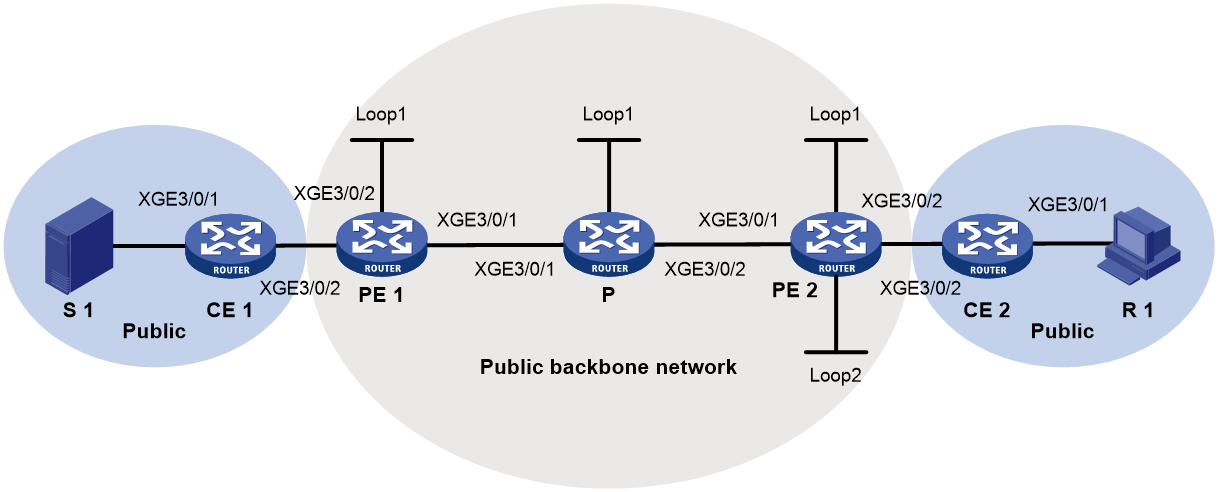
Table 2 Interface and IP address assignment
|
Device |
Interface |
IP address |
Device |
Interface |
IP address |
|
S 1 |
— |
10.110.7.2/24 |
R 1 |
— |
10.110.1.2/24 |
|
PE 1 |
XGE3/0/1 |
9000:6::1/64 |
P |
XGE3/0/1 |
9000:6::2/64 |
|
PE 1 |
XGE3/0/2 |
10.110.2.1/24 |
P |
XGE3/0/3 |
9000:8::2/64 |
|
PE 1 |
Loop1 |
1.1.1.1/32 1111::1111/128 |
P |
Loop1 |
2.2.2.2/32 2222::2222/128 |
|
PE 2 |
XGE3/0/1 |
9000:8::1/64 |
CE 1 |
XGE3/0/1 |
10.110.7.1/24 |
|
PE 2 |
XGE3/0/2 |
10.110.5.1/24 |
CE 1 |
XGE3/0/2 |
10.110.2.2/24 |
|
PE 2 |
Loop1 |
1.1.1.3/32 1113::1113/128 |
CE 2 |
XGE3/0/1 |
10.110.10.1/24 |
|
PE 2 |
Loop2 |
33.33.33.33/32 |
CE 2 |
XGE3/0/2 |
10.110.5.2/24 |
Procedure
1. Configure PE 1:
# Configure a global router ID.
<PE1> system-view
[PE1] router id 1.1.1.1
# Assign PE 1 to sub-domain 0, configure the BFR ID as 1, and configure the BFR prefix as the IPv6 address of Loopback 1.
[PE1] bier
[PE1-bier] sub-domain 0 ipv6
[PE1-bier-sub-domain-0-ipv6] bfr-id 1
[PE1-bier-sub-domain-0-ipv6] bfr-prefix interface LoopBack1
# Configure BIER with the G-BIER encapsulation.
[PE1-bier-sub-domain-0-ipv6] encapsulation-type g-bier bsl 128 max-si 32
# Configure 5001::1 as the multicast policy reserved address.
[PE1-bier-sub-domain-0-ipv6] g-bier mpra 5001::1
[PE1-bier-sub-domain-0-ipv6] quit
[PE1-bier] quit
# Configure a multicast service prefix.
[PE1] multicast-service-prefix ms1 ipv6-prefix 1234:1:: 64 service-id-length 10
# Create the public instance, and configure route targets for the public instance.
[PE1] ip public-instance
[PE1-public-instance] vpn-target 100:1 export-extcommunity
[PE1-public-instance] vpn-target 100:1 import-extcommunity
[PE1-public-instance] quit
# Enable IP multicast routing for the public instance.
[PE1] multicast routing
[PE1-mrib] quit
# Create a BIER-based MVPN for the public instance.
[PE1] multicast-vpn public-instance mode bier
# Create an MVPN IPv4 address family for the public instance.
[PE1-mvpn-public-instance] address-family ipv4
# Specify the MVPN source interface for the public instance.
[PE1-mvpn-public-instance-ipv4] source loopback 1
# Enable dynamic inclusive tunnel creation and dynamic selective tunnel creation for the public instance.
[PE1-mvpn-public-instance-ipv4] inclusive-tunnel dynamic sub-domain 0 bsl 128
[PE1-mvpn-public-instance-ipv4] selective-tunnel dynamic sub-domain 0 bsl 128
[PE1-mvpn-public-instance-ipv4] tunnel-source multicast-service-prefix ms1 service-id 12
[PE1-mvpn-public-instance-ipv4] quit
[PE1-mvpn-public-instance] quit
# Configure IS-IS.
[PE1] isis 1
[PE1-isis-1] is-level level-1
[PE1-isis-1] cost-style wide
[PE1-isis-1] bier enable
[PE1-isis-1] network-entity 10.0000.0000.0001.00
[PE1-isis-1] address-family ipv6 unicast
[PE1-isis-1-ipv6] quit
[PE1-isis-1] quit
# Assign an IP address to Ten-GigabitEthernet 3/0/1 on the public network, and enable IS-IS on it.
[PE1] interface ten-gigabitethernet 3/0/1
[PE1-Ten-GigabitEthernet3/0/1] ipv6 address 9000:6::1 64
[PE1-Ten-GigabitEthernet3/0/1 isis ipv6 enable 1
[PE1-Ten-GigabitEthernet3/0/1] quit
# Assign an IP address to Ten-GigabitEthernet 3/0/2 on the public network, and enable PIM-SM on it.
[PE1] interface ten-gigabitethernet 3/0/2
[PE1-Ten-GigabitEthernet3/0/2] ip address 10.110.2.1 24
[PE1-Ten-GigabitEthernet3/0/2] pim sm
[PE1-Ten-GigabitEthernet3/0/2] quit
# Assign an IP address to Loopback 1, and enable IS-IS on the interface.
[PE1] interface loopback 1
[PE1-LoopBack1] ip address 1.1.1.1 32
[PE1-LoopBack1] ipv6 address 1111::1111 128
[PE1-LoopBack1] isis ipv6 enable 1
[PE1-LoopBack1] quit
# Configure BGP.
[PE1] bgp 100
[PE1-bgp-default] peer 1113::1113 as-number 100
[PE1-bgp-default] peer 1113::1113 connect-interface loopback 1
[PE1-bgp-default] address-family ipv4 mvpn
[PE1-bgp-default-mvpn] peer 1113::1113 enable
[PE1-bgp-default-mvpn] quit
[PE1-bgp-default] address-family ipv4 unicast
[PE1-bgp-default-ipv4] mvpn-advertise-rt-import
[PE1-bgp-default-ipv4] peer 1113::1113 enable
[PE1-bgp-default-ipv4] peer 1113::1113 advertise-ext-community
[PE1-bgp-default-ipv4] import-route rip 2
[PE1-bgp-default-ipv4] import-route direct
[PE1-bgp-default-ipv4] quit
[PE1-bgp-default] quit
# Configure RIP.
[PE1] rip 2
[PE1-rip-2] network 10.110.2.0 0.0.0.255
[PE1-rip-2] import-route bgp
[PE1-rip-2] quit
2. Configure PE 2:
# Configure a global router ID.
<PE2> system-view
[PE2] router id 1.1.1.3
# Assign PE 2 to sub-domain 0, configure the BFR ID as 3, and configure the BFR prefix as the IPv6 address of Loopback 1.
[PE2] bier
[PE2-bier] sub-domain 0 ipv6
[PE2-bier-sub-domain-0-ipv6] bfr-id 3
[PE2-bier-sub-domain-0-ipv6] bfr-prefix interface LoopBack1
# Configure BIER with the G-BIER encapsulation.
[PE2-bier-sub-domain-0-ipv6] encapsulation-type g-bier bsl 128 max-si 32
# Configure 5003::1 as the multicast policy reserved address.
[PE2-bier-sub-domain-0-ipv6] g-bier mpra 5003::1
[PE2-bier-sub-domain-0-ipv6] quit
[PE2-bier] quit
# Create the public instance, and configure route targets for the public instance.
[PE2] ip public-instance
[PE2-public-instance] vpn-target 100:1 export-extcommunity
[PE2-public-instance] vpn-target 100:1 import-extcommunity
[PE2-public-instance] quit
# Enable IP multicast routing for the public instance.
[PE2] multicast routing
[PE2-mrib] quit
# Create a BIER-based MVPN for the public instance.
[PE2] multicast-vpn public-instance mode bier
# Create an MVPN IPv4 address family for the public instance.
[PE2-mvpn-public-instance] address-family ipv4
# Specify the MVPN source interface for the public instance.
[PE2-mvpn-public-instance-ipv4] source loopback 1
[PE2-mvpn-public-instance-ipv4] quit
[PE2-mvpn-public-instance] quit
# Configure IS-IS.
[PE2] isis 1
[PE2-isis-1] is-level level-1
[PE2-isis-1] cost-style wide
[PE2-isis-1] bier enable
[PE2-isis-1] network-entity 10.0000.0000.0003.00
[PE2-isis-1] address-family ipv6 unicast
[PE2-isis-1-ipv6] quit
[PE2-isis-1] quit
# Assign an IP address to Ten-GigabitEthernet 3/0/1 on the public network, and enable IS-IS on it.
[PE2] interface ten-gigabitethernet 3/0/1
[PE2-Ten-GigabitEthernet3/0/1] ipv6 address 9000:8::1 64
[PE2-Ten-GigabitEthernet3/0/1] isis ipv6 enable 1
[PE2-Ten-GigabitEthernet3/0/1] quit
# Assign an IP address to Ten-GigabitEthernet 3/0/2 on the public network, and enable PIM-SM on it.
[PE2] interface ten-gigabitethernet 3/0/2
[PE2-Ten-GigabitEthernet3/0/2] ip address 10.110.5.1 24
[PE2-Ten-GigabitEthernet3/0/2] pim sm
[PE2-Ten-GigabitEthernet3/0/2] quit
# Assign an IP address to Loopback 1, and enable IS-IS on the interface.
[PE2] interface loopback 1
[PE2-LoopBack1] ip address 1.1.1.3 32
[PE2-LoopBack1] ipv6 address 1113::1113 128
[PE2-LoopBack1] isis ipv6 enable 1
[PE2-LoopBack1] quit
# Assign an IP address to Loopback 2, and enable PIM-SM on the interface.
[PE2] interface loopback 2
[PE2-LoopBack2] ip address 33.33.33.33 32
[PE2-LoopBack2] pim sm
[PE2-LoopBack2] quit
# Configure Loopback 2 as a C-BSR and a C-RP of the public network.
[PE2] pim
[PE2-pim] c-bsr 33.33.33.33
[PE2-pim] c-rp 33.33.33.33
[PE2-pim] quit
# Configure BGP.
[PE2] bgp 100
[PE2-bgp-default] peer 1111::1111 as-number 100
[PE2-bgp-default] peer 1111::1111 connect-interface loopback 1
[PE2-bgp-default] address-family ipv4 mvpn
[PE2-bgp-default-mvpn] peer 1111::1111 enable
[PE2-bgp-default-mvpn]quit
[PE2-bgp-default] address-family ipv4 unicast
[PE2-bgp-default-ipv4] mvpn-advertise-rt-import
[PE2-bgp-default-ipv4] peer 1111::1111 enable
[PE2-bgp-default-ipv4] peer 1111::1111 advertise-ext-community
[PE2-bgp-default-ipv4] import-route rip 2
[PE2-bgp-default-ipv4] import-route direct
[PE2-bgp-default-ipv4] quit
[PE2-bgp-default] quit
# Configure RIP.
[PE2] rip 2
[PE2-rip-2] network 10.110.5.0 0.0.0.255
[PE2-rip-2] import-route bgp
[PE2-rip-2] quit
3. Configure P:
# Assign P to sub-domain 0, configure the BFR ID as 4, and configure the BFR prefix as the IPv6 address of Loopback 1.
[P] bier
[P-bier] sub-domain 0 ipv6
[P-bier-sub-domain-0-ipv6] bfr-id 4
[P-bier-sub-domain-0-ipv6] bfr-prefix interface LoopBack1
# Configure BIER with the G-BIER encapsulation.
[P-bier-sub-domain-0-ipv6] encapsulation-type g-bier bsl 128 max-si 32
# Configure 5004::1 as the multicast policy reserved address.
[P-bier-sub-domain-0-ipv6] g-bier mpra 5004::1
# Configure IS-IS.
[P] isis 1
[P-isis-1] is-level level-1
[P-isis-1] cost-style wide
[P-isis-1] bier enable
[P-isis-1] network-entity 10.0000.0000.0004.00
[P-isis-1] address-family ipv6 unicast
[P-isis-1-ipv6] quit
[P-isis-1] quit
# Assign an IP address to Ten-GigabitEthernet 3/0/1 on the public network, and enable IS-IS on it.
[P] interface ten-gigabitethernet 3/0/1
[P-Ten-GigabitEthernet3/0/1] ipv6 address 9000:6::2 64
[P-Ten-GigabitEthernet3/0/1] isis ipv6 enable 1
[P-Ten-GigabitEthernet3/0/1] quit
# Assign an IP address to Ten-GigabitEthernet 3/0/2 on the public network, and enable IS-IS on it.
[P] interface ten-gigabitethernet 3/0/2
[P-Ten-GigabitEthernet3/0/2] ipv6 address 9000:8::2 64
[P-Ten-GigabitEthernet3/0/2] isis ipv6 enable 1
[P-Ten-GigabitEthernet3/0/2] quit
# Assign an IP address to Loopback 1, and enable IS-IS on the interface.
[P] interface loopback 1
[P-LoopBack1] ip address 2.2.2.2 32
[P-LoopBack1] ipv6 address 2222::2222 64
[P-LoopBack1] isis ipv6 enable 1
[P-LoopBack1] quit
4. Configure CE 1:
# Enable IP multicast routing.
<CE1> system-view
[CE1] multicast routing
[CE1-mrib] quit
# Assign an IP address to Ten-GigabitEthernet 3/0/1 on the public network, and enable PIM-SM on it.
[CE1] interface ten-gigabitethernet 3/0/1
[CE1-Ten-GigabitEthernet3/0/1] ip address 10.110.7.1 24
[CE1-Ten-GigabitEthernet3/0/1] pim sm
[CE1-Ten-GigabitEthernet3/0/1] quit
# Assign an IP address to Ten-GigabitEthernet 3/0/2 on the public network, and enable PIM-SM on it.
[CE1] interface ten-gigabitethernet 3/0/2
[CE1-Ten-GigabitEthernet3/0/2] ip address 10.110.2.2 24
[CE1-Ten-GigabitEthernet3/0/2] pim sm
[CE1-Ten-GigabitEthernet3/0/2] quit
# Configure RIP.
[CE1] rip 2
[CE1-rip-2] network 10.110.2.0 0.0.0.255
[CE1-rip-2] network 10.110.7.0 0.0.0.255
[CE1-rip-2] quit
5. Configure CE 2:
# Enable IP multicast routing.
<CE2> system-view
[CE2] multicast routing
[CE2-mrib] quit
# Assign an IP address to Ten-GigabitEthernet 3/0/1 on the public network, and enable IGMP on it.
[CE2] interface ten-gigabitethernet 3/0/1
[CE2-Ten-GigabitEthernet3/0/1] ip address 10.110.10.1 24
[CE2-Ten-GigabitEthernet3/0/1] igmp enable
[CE2-Ten-GigabitEthernet3/0/1] quit
# Assign an IP address to Ten-GigabitEthernet 3/0/2 on the public network, and enable PIM-SM on it.
[CE2] interface ten-gigabitethernet 3/0/2
[CE2-Ten-GigabitEthernet3/0/2] ip address 10.110.5.2 24
[CE2-Ten-GigabitEthernet3/0/2] pim sm
[CE2-Ten-GigabitEthernet3/0/2] quit
# Configure RIP.
[CE2] rip 2
[CE2-rip-2] network 10.110.5.0 0.0.0.255
[CE2-rip-2] network 10.110.10.0 0.0.0.255
[CE2-rip-2] quit
Verifying the configuration
# Display information about the BIER inclusive tunnel for the public instance on PE 1.
[PE1] display multicast-vpn public-instance inclusive-tunnel local
Tunnel type: BIER
Tunnel interface: BIERVOif0
Tunnel state: Up
Flags: 0x30
Sub-domain ID/BSL: 0/128
BFR-ID: 1
BFR prefix: 1111::
Multicast service prefix:
Prefix length ID length ID offset MS Flags
64 10 0 0
Root: 1.1.1.1 (local)
Leafs:
1: BFR-ID: 3 BFR prefix: 1113::
Uptime: 00:09:50 Originating router: 1.1.1.3
# Display information about BIER selective tunnels for the public instance on PE 1.
[PE1] display multicast-vpn public-instance selective-tunnel local
Total 1 selective tunnel in using
Total 0 selective tunnel in creating
Tunnel type: BIER
Tunnel interface: BIERVOif1
Tunnel state: Up
Flags: 0x10
Sub-domain ID/BSL: 0/128
BFR-ID: 1
BFR prefix: 1111::
Multicast service prefix:
Prefix length ID length ID offset MS Flags
64 10 0 0
Root: 1.1.1.1 (local)
Leafs:
1: BFR-ID: 3 BFR prefix: 1113::
Uptime: 00:00:23 Originating router: 1.1.1.3
# Display C-multicast A-D route information for the public instance on PE 1.
[PE1] display multicast-vpn public-instance c-multicast routing-table
Total 0 (*, G) entry; 1 (S, G) entry
(10.110.7.2, 225.0.0.1)
CreateTime: 00:02:20
Tunnel Information: BIERVOif1
# Display information about the BIER inclusive tunnel for the public instance on PE 2.
[PE2] display multicast-vpn public-instance inclusive-tunnel remote
Total 1 inclusive tunnel
Tunnel type: BIER
Tunnel state: --
Flags: 0x0
Sub-domain ID/BSL: 0/128
BFR-ID: 1
BFR prefix: 1111::
Root: 1.1.1.1
Leaf:
1: BFR-ID: 3 BFR prefix: 1113::
Uptime: -- Originating router: 1.1.1.3
Troubleshooting BIER
BFR ID conflict
Symptom
The following log message is generated:
BIER/5/BIER_BFRID_CONFLICT_ACTIVE: -MDC=1; A BFR ID conflict exists. Address family=IPv6, Sub-domain=1, BFR ID=4, BFR prefixes=B::1,C::1.
Solution
To resolve the issue:
1. Identify the conflicting BFR edge devices through the BFR prefixes.
2. Modify the BFR ID for one of the two edge devices.
After the conflict is removed, the following log message is generated:
BIERRIB/5/BIER_BFRID_CONFLICT_CLEAR: -MDC=1; The BFR ID conflict was removed. Address family=IPv6, Sub-domain=1, BFR ID=4, BFR prefix=B::1.
