- Table of Contents
- Related Documents
-
| Title | Size | Download |
|---|---|---|
| 01-NAT configuration | 2.22 MB |
Contents
NAT entries and relation entries
Device access with overlapping addresses
Configuring outbound bidirectional NAT for internal-to-external access through domain name
Restrictions and guidelines: NAT configuration
Interface-based NAT tasks at a glance
Configuring basic features for global NAT
About configuring basic features for global NAT
Restrictions and guidelines for global NAT configuration
Prerequisites for global NAT configuration
Configuring global NAT (for NAT and BRAS unification)
Configuring global NAT (without NAT and BRAS unification)
Configuring a global address pool
Operating mechanism of global address pool
Configuring a static global address pool
Configuring a dynamic global address pool
Restrictions and guidelines for static NAT configuration
Prerequisites for static NAT configuration
Configuring outbound one-to-one static NAT
Configuring outbound net-to-net static NAT
Restrictions and guidelines for dynamic NAT configuration
Prerequisites for dynamic NAT configuration
Configuring outbound dynamic NAT
Configuring port allocation methods for PAT
Configuring NAT server mappings
Restrictions and guidelines for NAT server mapping configuration
Configuring common NAT server mappings on an interface
Configuring common NAT server mappings for global NAT
Configuring load sharing NAT server mappings on an interface
Configuring ACL-based NAT server mappings on an interface
Configuring port block-based NAT
Restrictions and guidelines for port block-based NAT configuration
Configuring static port block mapping on an interface
Configuring static port block mapping for global NAT
Configuring dynamic port block mapping on an interface
Configuring dynamic port block mapping for global NAT
Setting the maximum number of VPN users sharing one single public IP address
Enabling extended port block report
Configuring DS-Lite B4 address translation
Restrictions and guidelines for DS-Lite B4 address translation configuration
Prerequisites for DS-Lite B4 address translation configuration
Configuring DS-Lite B4 address translation on an interface
Configuring DS-Lite B4 address translation for global NAT
Specifying a NAT processing service card
Specifying a failover group for address translation
About specifying a failover group for NAT
Restrictions and guidelines for specifying a failover group
Prerequisites for specifying a failover group
Specifying a failover group for a NAT address group
Specifying a failover group for a NAT port block group
Specifying a failover group for an interface that provides Easy IP
Enabling flow-triggered port block assignment
Configuring centralized backup for distributed CGN
About centralized backup for distributed CGN
Restrictions and guidelines for centralized backup configuration for distributed CGN
Prerequisites for centralized backup configuration for distributed CGN
Configuring centralized backup for distributed CGN on a BRAS device (interface-based NAT)
Configuring centralized backup for distributed CGN on a CR (interface-based NAT)
Configuring centralized backup for distributed CGN on a BRAS device (global NAT)
Configuring centralized backup for distributed CGN on a CR (global NAT)
Configuring intra-device CGN hot backup
Configuring an intra-device service backup failover group
Configuring a failover group to process session-based services
Configuring inter-device CGN hot backup
Inter-device CGN hot backup tasks at a glance
Enabling inter-device CGN hot backup
Configuring a failover group for inter-device CGN hot backup
Configuring a service backup channel for inter-device CGN hot backup
Configuring a VRRP group on backup channel interfaces
Binding a failover group to a VRRP group based on the service backup channel
Configuring a failover group for processing session-based services
Associating a NAT instance with a VSRP instance
Configuring inter-device CGN warm backup in non-load-balancing mode
Inter-device CGN warm backup in non-load-balancing mode tasks at a glance
Configuring a CGN-UP backup profile (CPs)
Configuring a NAT instance associated with the warm-standby UP backup profile (CPs)
Configuring a failover group (UPs)
Configuring non-load-balancing mode (UPs)
Configuring a data backup channel for the NAT instance (UPs)
Setting up protection tunnels (UPs)
Configuring inter-device warm backup in load balancing mode
Inter-device warm backup in load balancing mode tasks at a glance
Configuring a UP backup group (CPs)
Configuring a UP backup profile (CPs)
Configuring a failover group (UPs)
Configuring load balancing mode (UPs)
Configuring a data backup channel for the NAT instance (UPs)
Configuring service backup and load balancing for global NAT
Limiting the rate of sending protocol packets to the CPU
Configuring NAT on the CUPS network
Enabling gratuitous ARP packet reply
Configuring NAT logging and SNMP notifications
Configuring NAT session logging
Configuring NAT444 user logging
Configuring NAT port block assignment failure logging
Configuring NAT port allocation failure logging
Configuring logging for failing to add an address to a global address pool
Configuring IP allocation failure logging for a global address pool
Configuring threshold violation and recovery logging
Configuring SNMP notifications for NAT
Display and maintenance commands for NAT
NAT configuration examples (non-CGN application scenarios)
Example: Configuring outbound one-to-one static NAT
Example: Configuring outbound dynamic NAT (non-overlapping addresses)
Example: Configuring NAT Server for external-to-internal access
Example: Configuring NAT Server for external-to-internal access through domain name
Example: Configuring NAT hairpin in C/S mode
Example: Configuring Twice NAT
Example: Configuring load sharing NAT Server
Example: Configuring NAT DNS mapping
Example: Configuring NAT log export to the information center
Example: Configuring NAT log export to the log server
NAT configuration examples (CGN application scenarios)
Example: Configuring outbound one-to-one static NAT
Example: Configuring outbound dynamic NAT (non-overlapping addresses)
Example: Configuring NAT static port block mapping
Example: Configuring NAT dynamic port block mapping
Example: Configuring DS-Lite B4 address translation
Example: Configuring intra-device hot backup for NAT and BRAS unification
Example: Configuring centralized backup for distributed CGN deployment
Example: Configuring NAT Server for external-to-internal access
Example: Configuring dynamic port block mapping in a NAT instance-based load balancing scenario
Example: Configuring multi-egress NAT
Example: Configuring NAT instance-based NAT Server and outbound NAT
Example: Configuring UP backup on a CUPS network
Example: Configuring UP backup on a CUPS network (support for protection tunnels)
Example: Configuring inter-device warm backup in non-load-balancing mode on a CUPS network
Example: Configuring inter-device warm backup in load balancing mode on a CUPS network
NAT overview
The term "CGN card" in this document refers to a CGN-capable card.
Network Address Translation (NAT) translates an IP address in the IP packet header to another IP address. Typically, NAT is configured on gateways to enable private hosts to access external networks and external hosts to access private network resources such as a Web server.
Basic NAT concepts
The following describes basic NAT concepts:
· NAT device—A device configured with NAT. Typically, NAT is configured on the edge device that connects the internal and external networks.
· NAT interface—An interface configured with NAT.
· NAT rule—A rule that NAT follows to translate addresses.
· NAT address—A public IP address used for address translation, and this address is reachable from the external network. The NAT address can be manually assigned or dynamically obtained.
· NAT entry—Stores the mapping between a private IP address and a public IP address. For more information, see "NAT entries."
· Easy IP—Uses the IP address of an interface as the NAT address. The IP address of the interface can be manually assigned or be obtained through DHCP or PPPoE.
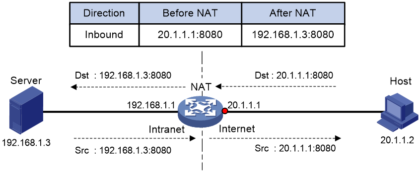
Basic NAT operating mechanism
Figure 1 shows the basic NAT operating mechanism.
2. Upon receiving a response from the server, NAT translates the destination public address to the private address, and forwards the packet to the host.
The NAT operation is transparent to the terminals (the host and the server). NAT hides the private network from the external users and shows that the IP address of the internal host is 20.1.1.1.

NAT applications
Traditional NAT
Traditional NAT is configured on the interface that connects to the public network. It translates the source IP addresses of outgoing packets and destination IP addresses of incoming packets.
Twice NAT
Twice NAT translates the destination IP address on the receiving interface, and the source IP address on the sending interface. The receiving and sending interfaces are both NAT interfaces.
Twice NAT allows VPNs with overlapping addresses to access each other.
Bidirectional NAT
NAT translates the source and destination IP addresses of incoming packets on the receiving interface and outgoing packets on the sending interface.
Bidirectional NAT supports active access to external network resources from internal users when the internal and external IP addresses overlap.
NAT hairpin
NAT hairpin allows internal hosts to access each other through NAT. The source and destination IP address of the packets are translated on the interface connected to the internal network.
NAT hairpin includes P2P and C/S modes:
· P2P—Allows internal hosts to access each other through NAT. The internal hosts first register their public addresses to an external server. Then, the hosts communicate with each other by using the registered IP addresses.
· C/S—Allows internal hosts to access internal servers through NAT addresses. The destination IP address of the packet going to the internal server is translated by matching the NAT Server configuration. The source IP address is translated by matching the outbound dynamic or static NAT entries.
NAT DNS mapping
The DNS server is typically on the public network. For the users on the public network to access an internal server, you can configure the NAT Server feature on the NAT interface that connects to the public network. The NAT Server maps the public IP address and port number to the private IP address and port number of the internal server. Then the public users can access the internal server through the server's domain name or public IP address.
When a user is in the private network, the user cannot access the internal server by using the domain name of the server. This is because the DNS response contains the public IP address of the server. In this case, you can configure NAT DNS mapping to solve the problem.

As shown in Figure 2, NAT DNS mapping works as follows:
1. The host sends a DNS request containing the domain name of the internal Web server.
2. Upon receiving the DNS response, the NAT device performs a DNS mapping lookup by using the domain name in the response. A NAT DNS mapping maps the domain name to the public IP address, public port number, and the protocol type for the internal server.
3. If a match is found, the NAT continues to compare the public address, public port number, and the protocol type with the NAT Server configuration. The NAT Server configuration maps the public IP address and port number to the private IP address and port number for the internal server.
4. If a match is found, NAT translates the public IP address in the response into the private IP address of the Web server.
5. The internal host receives the DNS response, and obtains the private IP address of the Web server.
NAT control
You can use ACLs to implement NAT control. The match criteria in the ACLs include the source IP address, source port number, destination IP address, destination port number, transport layer protocol, user group, and VPN instance. Only packets permitted by an ACL are processed by NAT.
NAT translation methods
Static NAT
Static NAT creates a fixed mapping between a private address and a public address. It supports connections initiated from internal users to external network and from external users to the internal network. Static NAT applies to regular communications.
Dynamic NAT
Dynamic NAT uses an address pool to translate addresses. It applies to the scenario where a large number of internal users access the external network.
NO-PAT
Not Port Address Translation (NO-PAT) translates a private IP address to an IP public address. The public IP address cannot be used by another internal host until it is released.
NO-PAT supports all IP packets.
PAT
Port Address Translation (PAT) translates multiple private IP addresses to a single public IP address by mapping the private IP address and source port to the public IP address and a unique port. PAT supports TCP and UDP packets, and ICMP request packets.
Figure 3 PAT operation

As shown in Figure 3, PAT translates the source IP addresses of the three packets to the same IP public address and translates their port numbers to different port numbers. Upon receiving a response, PAT translates the destination address and port number of the response, and forwards it to the target host.
PAT supports the following mappings:
· Endpoint-Independent Mapping (EIM)—Uses the same IP and port mapping (EIM entry) for packets from the same source IP and port to any destinations. EIM allows external hosts to initiate connections to the translated IP addresses and ports of internal hosts. It allows internal hosts behind different NAT gateways to access each other.
· Address and Port-Dependent Mapping (APDM)—Uses different IP and port mappings for packets from the same source IP and port to different destination IP addresses and ports. APDM allows an external host to initiate connections to an internal host only under the condition that the internal host has previously accessed the external host. It is secure, but it does not allow internal hosts behind different NAT gateways to access each other.
· Connection-Dependent Mapping—Uses the same IP and port mapping for packets of the same connection. Different IP and port mappings are used for different connections although the connections might have the same source IP address and port number. It is secure because it allows an external host to access an internal host only under the condition that the internal host has previously accessed the external host.
NAT Server
The NAT Server feature maps a public address and port number to the private IP address and port number of an internal server. This feature allows servers in the private network to provide services for external users.
Figure 4 shows how NAT Server works:
1. Upon receiving a request from the host, NAT translates the public destination IP address and port number to the private IP address and port number of the internal server.
2. Upon receiving a response from the server, NAT translates the private source IP address and port number to the public IP address and port number.
Port block-based NAT
Port block-based NAT is a PAT translation based on port ranges. It maps multiple private IP addresses to one public IP address and uses a different port block for each private IP address. For example, the private IP address 10.1.1.1 of an internal host is mapped to the public IP address 202.1.1.1 and port block 10001 to 10256. When the internal host accesses public hosts, the source IP address 10.1.1.1 is translated to 202.1.1.1, and the source ports are translated to ports in the port block 10001 to 10256.
Port block-based NAT includes static and dynamic mappings. It applies to NAT444 and DS-Lite networks.
Static port block mapping
The NAT gateway computes a static port block mapping before address translation. The mapping is between a private IP address and a public IP address with a port block.
When an internal user initiates a connection to the external network, the system performs the following operations:
· Locates a static mapping based on the private IP address of the user and obtains the public IP address and the port block in the mapping.
· Selects a public port number in the port block.
· Translates the private IP address to the public IP address and assigns the selected public port number.
The NAT gateway uses private IP addresses, public IP addresses, a port range, and a port block size to compute static mappings:
1. Divides the port range by the port block size to get the number of available port blocks for each public IP address.
This value is the base number for mapping.
2. Sorts the port blocks in ascending order of the start port number in each block.
3. Sorts the private IP addresses and the public IP addresses separately in ascending order.
4. Maps the first base number of private IP addresses to the first public IP address and its port blocks in ascending order.
For example, the number of available port blocks of each public IP address is m. The first m private IP addresses are mapped to the first public IP address and the m port blocks in ascending order. The next m private IP addresses are mapped to the second IP address and the m port blocks in ascending order. The other static port block mappings are created by analogy.
Dynamic port block mapping
In the NAT and BRAS unification scenario, the device operates as follows:
1. When a user passes authentication, the device looks up NAT configuration on all interfaces for a matching ACL for the user traffic.
2. If a matching ACL in all NAT configuration is found, the device assigns public IP address and a port block to the user, and creates a dynamic port block mapping.
3. After the user goes offline, the device reclaims the port block and deletes the dynamic port block mapping.
In scenarios without unification, when an internal user initiates a connection to the external network, the dynamic port block-based NAT operates as follows:
1. Uses ACLs to implement translation control. It processes only packets that match an ACL permit rule.
2. Creates a mapping from the internal user's private IP address to a public IP address and a port block.
3. Translates the private IP address to the public IP address, and the source ports to ports in the selected port block for subsequent connections from the private IP address.
4. Withdraws the port block and deletes the dynamic port block mapping when all connections from the private IP address are disconnected.
Dynamic port block mapping supports port block extending. If the ports in the port block for a private address are all occupied, dynamic port block mapping translates the source port to a port in an extended port block.
NAT entries and relation entries
NAT session entry
NAT creates a NAT session entry for a session and creates an address mapping for the first packet in the session.
A NAT session entry contains extended NAT information, such as interface and translation method. Subsequent packets of the session are translated by using this entry.
· If the direction of the subsequent packets is the same as the direction of the first translated packet, NAT performs the source and destination address translation the same as the first packet.
· If the direction of the subsequent packets is opposite to the direction of the first translated packet, NAT perform reverse address translation. For example, if the source address of the first packet is translated, then the destination address of the subsequent packets is translated.
The session management module maintains the updating and aging of NAT session entries. For information about session management, see Security Configuration Guide.
EIM entry
If EIM is configured on the NAT device, the PAT mode will first create a NAT session entry, and then an EIM entry. The EIM entry is a 3-tuple entry, and it maps a private address/port to a public address/port. The EIM entry ensures:
· Subsequent new connections originating from the same source IP and port uses the same translation as the initial connection.
· Translates the address for new connections initiated from external hosts to the NAT address and port number based on the EIM entry.
An EIM entry ages out after all related NAT session entries age out.
NO-PAT entry
A NO-PAT entry maps a private address to a public address. The same mapping applies to subsequent connections originating from the same source IP.
A NO-PAT entry can also be created during the ALG process for NAT. For information about NAT ALG, see "NAT ALG."
A NO-PAT entry ages out after all related NAT session entries age out.
Port block-based entry
A port block-based entry maps a private IP address to a public IP address and a port block.
Port block-based entries include static and dynamic port block mappings. For information about these mappings, see "Static port block mapping" and "Dynamic port block mapping."
Relation entry
NAT ALG translates the IP addresses or port numbers contained in the payload of application-layer packets. On receiving the first packet, the NAT device enabled with ALG creates a relation entry to record the address information carried in the packet. Subsequent packets of the session are translated by using this entry. The address and port information after NAT is used to establish a dynamic channel, and subsequent connections that match the address information will transmit data through the dynamic channel. For more information about relation entries, see session management in Security Configuration Guide.
VRF-aware NAT
VRF-aware NAT allows users from different VRF (VPN instances) to access external networks and to access each other.
1. Upon receiving a request from a user in a VRF to an external network, NAT performs the following tasks:
¡ Translates the private source IP address and port number to a public IP address and port number.
¡ Records the VRF information, such as the VRF name.
2. When a response packet arrives, NAT performs the following tasks:
¡ Translates the destination public IP address and port number to the private IP address and port number.
¡ Forwards the packet to the target VRF.
The NAT Server feature supports VRF-aware NAT for external users to access the servers in a VPN instance. For example, to enable a host at 10.110.1.1 in VPN 1 to provide Web services for Internet users, configure NAT Server to use 202.110.10.20 as the public IP address of the Web server.
NAT ALG
NAT ALG (Application Level Gateway) translates address or port information in the application layer payloads to ensure connection establishment.
For example, an FTP application includes a data connection and a control connection. The IP address and port number for the data connection depend on the payload information of the control connection. This requires NAT ALG to translate the address and port information for data connection establishment.
CGN
About CGN
Carrier Grade NAT (CGN), also called Large-scale NAT (LSN), is typically deployed in the ISP network. Traditionally NAT is deployed on the CPE devices for address translation of few users. CGN translates addresses for a large number of users by installing CGN cards on devices such as the BRAS devices. Meanwhile, CGN supports more concurrent users, higher performance, and better user tracing.
CGN is applicable to multiple scenarios, such as NAT444 and DS-Lite.
CGN deployment
CGN deployment falls into the following types based on the CGN card location:
· Centralized CGN deployment—A CGN-capable device is close to or at the core of MAN, typically deployed on a core router (CR) device. To implement the deployment, you can connect devices with CGN cards installed to the core routers (Figure 5) or install CGN cards on the core routers (Figure 6).
This deployment is applicable to a network with a small number of users and traffic.
Figure 5 Connecting core routers to devices with CGN cards installed

Figure 6 Installing CGN cards on the core routers

· Distributed CGN deployment—A CGN-capable device is close to or at the edge of MAN, typically deployed on a BRAS device. As is shown in Figure 7, to implement distributed CGN deployment, a CGN card is installed on each BRAS device.
Distributed CGN deployment is applicable to a network with a large number of users and traffic.
Figure 7 Distributed CGN deployment

CGN backup
The CGN backup feature ensures service continuity and provides high availability for the ISP network.
Centralized backup for distributed CGN deployment
This backup plan allows a centralized CGN device to provide backup services for distributed CGN deployment. When a distributed CGN device fails, the centralized CGN device provides address translation.
As shown in Figure 8, the BRAS device provides AAA for users, the core router groups and forwards data traffic. Traffic is NATed by the CGN card on the BRAS device. When the CGN card on the BRAS device fails, traffic is redirected to the CGN card on the core router for NAT processing.
Figure 8 Centralized backup for distributed CGN deployment

Traffic is redirected to the CGN card on the core router (CR) by the following methods:
· BRAS routing—The BRAS sends the traffic to the CR based on the routing table, as is shown in Figure 9. On the CAR, the QoS policy redirects the traffic to the CGN card. After the CGN card on the BRAS device recovers, the QoS policy on the BRAS takes effect again and directs traffic to its CGN card.
Figure 9 Centralized backup for distributed CGN deployment (through BRAS routing)

· GRE tunneling between BRAS and CR—Traffic is redirected to the next hop by the QoS policy on the BRAS device and then sent to the CR through GRE tunneling. On the CR, traffic is redirected to the CGN card through a QoS policy. After the CGN card on the BRAS device recovers, the QoS policy on the BRAS directs traffic to the failover group on the BRAS device. The traffic is NATed on the primary node (CGN card) of the failover group.
Figure 10 Centralized backup for distributed CGN (through GRE tunneling)

If you use the BRAS routing method, make an overall network planning on private IP addresses because the private IP routes might enter MAN. The GRE tunneling method can avoid this issue, but it requires a dedicated GRE tunnel and a QoS policy for redirecting traffic to an interface on the CR. For more information about GRE tunneling, see "Configuring GRE."
Intra-device CGN backup
This backup plan refers to the backup among multiple CGN cards on the same device. It supports the following backup methods:
· Warm backup—Backs up port block entries but no session entries. After switchover, public IP-private IP mappings do not change, but sessions are re-established.
· Hot backup—Backs up port block entries and session entries. After switchover, public IP-private IP mappings do not change and the session re-establishment are not needed.
You can create one, two, or multiple failover groups to implement intra-device backup for centralized CGN deployment and distributed CGN deployment. For more information about failover groups, see High Availability Configuration Guide.
For example, use two CGN cards on the BRAS to create one failover group as is shown in Figure 11. The primary node CGN 1 in the failover group provides NAT services. When the primary node operates incorrectly, as is shown in Figure 12, the secondary node CGN 2 takes over to provide NAT services.
Figure 11 Intra-device CGN backup (when CGN 1 operates correctly)

Figure 12 Intra-device CGN backup (when CGN 2 operates incorrectly)

Inter-device CGN backup
This backup plan uses a VRRP group containing two devices, each having one CGN card configured as a node in a failover group. The failover group determines the node status based on the device role in the VRRP group. If the master device fails or the link fails, the failover group activates the node on the new elected master. This feature ensures service continuity during the master/backup switchover. For more information about VRRP and failover groups, see High Availability Configuration Guide.
Inter-device CGN backup supports the following backup methods:
· Warm backup—Backs up port block entries but no session entries. After switchover, public IP-private IP mappings do not change, but sessions are re-established.
· Hot backup—Backs up port block entries and session entries. After switchover, public IP-private IP mappings do not change and the sessions re-establishment are not needed.
For inter-device CGN backup, the two nodes can work in either of the following modes:
· The primary node processes services and backs up service data to the secondary node.
· Both nodes can process services and back up data to each other.
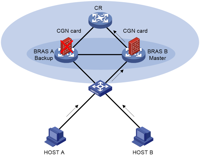
As shown in Figure 13, BRAS A and BRAS B forms one VRRP group, and BRAS A is the master device in the VRRP group. As the primary node in a session-based failover group, the CGN card on BRAS A processes NAT services and backs up service data to the CGN card on BRAS B. As shown in Figure 14, when the CGN card on BRAS A fails, BRAS B becomes the master device, and the CGN card on BRAS B becomes the primary node to process NAT services.
Figure 13 Inter-device CGN backup (when the CGN card on BRAS A operates correctly)

Figure 14 Inter-device CGN backup (when the CGN card on BRAS A operates incorrectly)
Inter-device CGN warm backup in non-load-balancing mode
In a vBRAS CUPS scenario, this backup plan uses the NAT instances of multiple master UP devices and one backup UP device. Inter-device CGN warm backup in non-load-balancing mode works as follows:
· The CP determines the master or backup role of a UP. Only the NAT instance in active state on the master UP processes NAT services.
· The master UP devices back up user table information to the backup UP device. When the backup UP device switches to a master UP device, it attempts to translate addresses according to the user entries for user tracing.
The example in Figure 15 uses two master UP devices and one backup UP to implement inter-device CGN warm backup in non-load-balancing mode.
1. Assign UP A, UP B, and UP C to one UP backup group.
2. Creates NAT instance 1 on CP, UP A, UP B, and UP C, respectively. Configure the same NAT rule for each NAT instance on UPs.
3. Create a warm-standby CGN-UP backup profile on the CP and bind it to NAT instance 1. UP A and UP B act as master UPs and UP C acts as the backup UP. The CGN cards of NAT instances on UP A and UP B back up data to the CGN card of the NAT instance on UP C.
4. Use UP A and UP C as peer devices in VSRP instance 1.
5. Use UP B and UP C as peer devices in VSRP instance 2.
6. Bind the NAT instances on UP A and UP C to VSRP instance 1. NAT creates a service backup channel to back up session entries.
7. Bind the NAT instances on UP B and UP C to VSRP instance 2. NAT creates a service backup channel to back up session entries.
Then the inter-device CGN warm backup in non-load-balancing mode works as follows:
1. When UP A and UP B work correctly, the CGN cards of each NAT instance 1 on UP A and UP B process NAT services and back up user entries to UP C through the backup channels.
2. If the CGN card of NAT instance 1 on UP A fails and the NAT instance is inactive, the CP switches UP C to a master UP. The CGN card of NAT instance 1 on UP C processes NAT services. The backup UP provides backup services only for the master UP that fails first. If an additional master UP fails, no more backup UPs are available, and NAT services on the master UP are faulty. For more information, see UP backup configuration in CP and UP Separation Configuration Guide.
Figure 15 Inter-device CGN warm backup in non-load-balancing mode

Inter-device CGN warm backup in load balancing mode
In this backup plan, each UP has a master interface. Each master interface forms a backup relationship with each of the N master interfaces. The CP determines the master or backup role of a UP. The backup plan works as follows:
1. When a user comes online, UCM on CP specifies a master interface for the user and chooses one of the N master interfaces as the backup interface. The master interface and backup interface forms a backup relationship, which can serve multiple users.
2. Upon receiving the user coming online message from UCM, the CGN on the UP generates NAT subinstances based on the parent NAT instance carried in the user coming online message. The CGN also associates the NAT subinstances with the user. The NAT subinstances process address translation services. The backup relationship of the NAT subinstances is determined by UCM.
3. When user traffic reaches the master interface, the UP performs address translation based on the CGN policy.
4. The CGN backs up the following information on the UP where the master interface resides to the UP where the backup interface resides.
¡ User table information.
¡ Address range information for global address pools.
¡ Address member information for NAT address groups.
When the backup interface switches to a master interface, the public addresses do not change on the UP where the new master interface resides.
For more information about UP backup and UCM, see BRAS Services Configuration Guide.
Figure 16 describes how to set up an inter-device CGN warm backup environment in load balancing mode.
1. Assign UP A, UP B, and UP C to one UP backup group.
2. Create NAT instance 1 on CP, UP A, UP B, and UP C, respectively. Configure the same NAT rule for each NAT instance on UPs.
3. Create a VSRP instance for each backup relationship on UP A, UP B, and UP C, respectively.
4. Bind the NAT instance to the VSRP instance on UP A, UP B, and UP C, respectively. NAT creates a service backup channel to back up the user table information, address range information for global address pools, and address member information for NAT address groups.
In the following example, the master interface on UP A is in master state. Inter-device CGN warm backup in load balancing mode works as follows:
1. When the master interface on UP A works correctly, the CGN card in NAT instance 1 on UP A processes NAT services. If the VSRP instance group associated with the NAT instance contains multiple failover groups, NAT assigns NAT services evenly to each failover group based on the load balancing algorithm.
2. UP A backs up the user table information, address range information for global address pools, and address member information for NAT address groups of NAT instance 1 to UP B and UP C through the backup channel.
3. If the master interface on UP A fails, the CUSP channel between the CP and UP A fails, or the CP monitors other exceptions, the CP notifies UP A to degrade its master interface to a backup interface and notifies UP B and UP C to upgrade their interfaces to master interfaces.
4. After user traffic reaches the master interfaces of UP B and UP C, UP B and UP C perform address translation according to the backup information and their own CGN policy.
Figure 16 Inter-device CGN warm backup in load balancing mode

NAT444
About NAT444
NAT444 provides carrier-grade NAT by unifying the NAT444 gateway, AAA server, and log server. NAT444 introduces a second layer of NAT on the carrier side, with few changes on the customer side and the application server side. With port block assignment, NAT444 supports user tracking. It has become a preferred solution for carriers in transition to IPv6.
The NAT444 solution can be centralized and distributed deployment.
Centralized NAT444 deployment
Centralized NAT444 deployment is implemented by installing a NAT service card on the core router or by connecting a NAT444 device to the CR.
As shown in Figure 17, when an internal user accesses the external network, NAT444 is implemented as follows:
1. The CPE device performs the first NAT.
2. After the user passes AAA authentication on the BRAS device, this user is assigned a private IP address.
3. When the packet destined to the external network, the NAT444 gateway performs the second NAT.
Figure 17 Centralized NAT444 deployment

Distributed NAT444 deployment
Distributed NAT444 deployment is implemented by installing a NAT service card on the BRAS device. This deployment also requires the unification of NAT444 gateway and the BRAS device. To unify the NAT444 gateway and BRAS device, specify the user address type in the ISP domain.
As shown in Figure 18, the NAT444 gateway and BRAS device function as follows after the unification:
1. After a user passes authentication and obtains a private address, the NAT444 gateway immediately assigns a public IP address and a port block to the user.
If the NAT444 resources have been used up, the BRAS logs off the user, which ensures accurate accounting on the AAA server.
2. The NAT444 gateway sends the port block mapping to the BRAS device.
3. The BRAS device records the mapping and reports it to the AAA server.
The AAA server maintains one mapping for each online user until the user goes offline. The unification ensures that the AAA server maintains mappings for all users and provides user tracing without requiring an extra log server.
Only the unification between the NAT444 gateway and the PPPoE or IPoE service is supported in the current software version.
Figure 18 Distributed NAT444 deployment

Device access with overlapping addresses
Configuring twice NAT
As shown in Figure 19, two hosts are in different VPN instances with overlapping addresses. For the hosts to access each other, both the source and destination addresses of packets between the two VPNs need to be translated. Configure static NAT on both interfaces connected to the VPNs on the NAT device.
1. Configure a static outbound NAT mapping between 192.168.1.1 in VPN 1 and 172.16.1.1 in VPN 2.
2. Configure a static outbound NAT mapping between 192.168.1.1 in VPN 2 and 172.16.2.1 in VPN 1.
3. When the twice NAT takes effect, the hosts can access each other.
Figure 19 VPN access with overlapping address

Configuring outbound bidirectional NAT for internal-to-external access through domain name
As shown in Figure 20, the IP address of the Web server overlaps with the private host at 192.168.1.0/24. Configure dynamic NAT ALG and outbound dynamic NAT to allow the internal host to access the external Web server by using the server's domain name.
1. The host sends a DNS request to the DNS server in the external network.
2. After receiving a DNS reply, the NAT device with NAT ALG configured translates the Web server's IP address in the DNS reply payload to a dynamically assigned public address 10.1.1.1.
3. Configure inbound dynamic NAT ALG to make sure the internal host reaches the Web server instead of another internal host. NAT ALG can translate the Web server's IP address in the DNS reply payload to a dynamically assigned public address 10.1.1.1.
4. After receiving the DNS reply from the NAT device, the host sends a packet with the source IP address 192.168.1.1 and destination IP address 10.1.1.1.
5. The NAT device with outbound dynamic NAT configured translates the source IP address of the packet to a dynamically assigned public address 20.1.1.1. NAT ALG translates the destination IP address of the packet to the IP address of the Web server.
Figure 20 Internal-to-external access through domain name

NAT in the DS-Lite network
Dual Stack Lite (DS-Lite) is a combination of the tunneling and NAT technologies. NAT translates the private IPv4 addresses of the IPv4 hosts before the hosts reach the IPv4 public network. For more information about DS-Lite, see "IPv4 over IPv6 tunneling."
As the gateway of the private network, the B4 element is responsible for the encapsulation and de-encapsulation of tunneled packets. DS-Lite B4 address translation is configured on the AFTR and performs port block-based translation based on the IPv6 address of the B4 element. DS-Lite B4 address translation dynamically maps a public IPv4 address and a port block to the IPv6 address of the B4 element. Hosts behind the B4 element use the mapped public IPv4 address and port block to access the public IPv4 network.
DS-Lite B4 address translation supports user tracing based on the port block.
Figure 21 DS-Lite B4 address translation

Configuring NAT
Restrictions and guidelines: NAT configuration
According to the application scope of NAT rules, NAT supports the following application types:
· Interface-based NAT—Uses NAT rules configured on a per interface basis to translate packets.
· Global NAT—Uses NAT rules configured on a per NAT instance basis to translate packets. The packets are redirected to the NAT instance by using a QoS policy.
Interface-based NAT and global NAT are mutually exclusive. Interface-based NAT and NAT instances cannot be both configured. To configure global NAT, you must first delete existing NAT configurations on all interfaces. To configure interface-based NAT, you must first delete all existing NAT instance configurations.
The general restrictions and guidelines are as follows:
· If you perform all the translation methods, the NAT rules are sorted in the following descending order:
a. NAT Server.
b. Static NAT.
c. NAT static port blocking mapping.
d. Dynamic NAT, DS-Lite B4 address translation, and NAT dynamic block mapping.
Dynamic NAT, NAT dynamic port block mapping, and DS-Lite B4 address translation have the same priority. DS-Lite B4 address translation rules are effective for IPv6 packets.
Dynamic NAT rules and NAT dynamic port block mapping rules are sorted in descending order of ACL numbers and are effective for IPv4 packets.
· After NAT is configured, editing the ACL rule in a QoS policy affects only subsequent traffic and does not affect the NATed traffic.
· When you use a QoS policy to redirect traffic to a NAT instance, the device works as follows:
If the QoS policy applied to an interface or applied globally and the policy-based routing configured on the interface matches the same traffic (for example, they use the same ACL rule), the policy-based routing takes effect. The device does not match the traffic with the QoS policy.
· To ensure successful packet forwarding in the DS-Lite network, make sure the MTU value of the physical output interface on the DS-Lite tunnel is greater than that of the DS-Lite tunnel interface by a minimum of 40 bytes.
· After you switch the traffic redirecting action to redirecting traffic to a specified card, or from redirecting to a specified card to another redirecting action, clear the fast forwarding table for the card by using the reset ip fast-forwarding cache slot command.
· Address translation in non-VPN instances or in the same VPN instance is available only for the following cards:
Table 1 Card information
|
Card category |
Cards |
|
CEPC |
CEPC-XP4LX, CEPC-XP24LX, CEPC-XP48RX, CEPC-CP4RX, CEPC-CP4RXA, CEPC-CP4RX-L |
|
CSPEX |
CSPEX-1304X, CSPEX-1404X, CSPEX-1502X, CSPEX-1504X, CSPEX-1504XA, CSPEX-1602X, CSPEX-1602XA, CSPEX-1804X, CSPEX-1512X, CSPEX-1612X, CSPEX-1812X |
|
SPE |
RX-SPE200 |
Make sure the ACL rule used for address translation contains a minimum of one match criterion listed for the scenario in Table 2.
Table 2 Match criteria of an ACL rule in specific scenarios
|
Scenario |
Match criteria |
|
Common unification user access |
Source IP address, VPN instance, or user group. |
|
Load sharing unification user access |
User group. |
|
Port block assignment triggered by traffic |
Source IP address, VPN instance, source port, protocol type, or user group. |
When you configure BRAS unification, follow these restrictions and guidelines:
· Supported user address types are private IPv4 address, private-DS address, and DS-Lite address.
· The NAT port block configuration can be modified only after all users go offline.
If all equal-cost output interfaces are configured with interface-based NAT, make sure the NAT configurations on all them are the same. If the NAT configurations are different, NAT uses the NAT configuration on only one interface for address translation, leading to unexpected results and NAT address waste.
Global NAT tasks at a glance
To configure global NAT, perform the following tasks:
1. Configuring basic features for global NAT
2. Configuring a global address pool
3. Configuring address translation and port allocation methods for global NAT
¡ Configuring outbound one-to-one static NAT for global NAT
¡ Configuring outbound net-to-net static NAT for global NAT
¡ Configuring outbound dynamic NAT for global NAT
¡ Configuring port allocation methods for PAT
¡ Configuring common NAT server mappings for global NAT
¡ Configuring static port block mapping for global NAT
¡ Configuring dynamic port block mapping for global NAT
¡ Configuring DS-Lite B4 address translation for global NAT
4. (Optional.) Setting the maximum number of VPN users sharing one single public IP address
5. (Optional.) Enabling extended port block report
6. (Optional.) Configuring high availability for NAT
¡ Configuring centralized backup for distributed CGN
¡ Configuring intra-device CGN hot backup
¡ Configuring inter-device CGN hot backup
¡ Configuring inter-device CGN warm backup in non-load-balancing mode
¡ Configuring inter-device warm backup in load balancing mode
¡ Configuring service backup and load balancing for global NAT
7. (Optional.) Limiting the rate of sending protocol packets to the CPU
8. (Optional.) Configuring NAT on the CUPS network
9. (Optional.) Configuring NAT DNS mapping
10. (Optional.) Configuring NAT ALG
11. (Optional.) Enabling gratuitous ARP packet reply
12. (Optional.) Configuring NAT logging and SNMP notifications
Interface-based NAT tasks at a glance
To configure NAT on an interface, perform the following tasks:
1. Configuring a translation method and port allocation on an interface
¡ Configuring outbound dynamic NAT for interface-based NAT
¡ Configuring port allocation methods for PAT
¡ Configuring common NAT server mappings on an interface
¡ Configuring load sharing NAT server mappings on an interface
¡ Configuring ACL-based NAT server mappings on an interface
¡ Configuring static port block mapping on an interface
¡ Configuring dynamic port block mapping on an interface
¡ Configuring DS-Lite B4 address translation on an interface
2. Specifying a slot for processing NAT services
Choose one of the following options to configure as needed:
¡ Specifying a NAT processing service card
To use a NAT-capable service card for NAT service processing, specify this service card on an interface with NAT configured.
¡ Specifying a failover group for address translation
To enable the specified CGN card to process NAT service, you must also configure QoS policies.
3. (Optional.) Setting the maximum number of VPN users sharing one single public IP address
4. (Optional.) Enabling extended port block report
5. Enabling flow-triggered port block assignment
This feature is required for interface-based NAT if CGN cards use port block mappings for address translation and no BRAS unification is configured.
6. (Optional.) Configuring high availability for NAT
¡ Configuring centralized backup for distributed CGN
¡ Configuring intra-device CGN hot backup
¡ Configuring inter-device CGN hot backup
7. (Optional.) Limiting the rate of sending protocol packets to the CPU
8. (Optional.) Configuring NAT hairpin
9. (Optional.) Configuring NAT DNS mapping
10. (Optional.) Configuring NAT ALG
11. (Optional.) Configuring NAT logging and SNMP notifications
Configuring basic features for global NAT
About configuring basic features for global NAT
Global NAT is applicable to a network with unfixed output interfaces. You do not need to change the global NAT configuration if the packet output interface changes.
Because a CGN card does not have interfaces for service processing, a QoS policy is required to redirect traffic from the egress interface card to the CGN card. Global NAT is implemented as follows:
· A service instance group is associated with a NAT instance and a failover group that contains CGN card nodes. For more information about configuring service instance groups and failover groups, see High Availability Configuration Guide.
· A QoS policy is used to redirect the traffic to the NAT instance. The primary node in the failover group performs address translation for traffic that matches the rules in the NAT instance.
Analysis
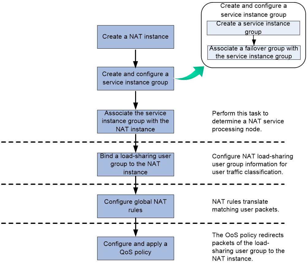
In the NAT and BRAS unification scenario, the access device assigns an online user a load-sharing user group and a NAT instance. The device then uses a QoS policy to redirect user packets of the load-sharing user group to a NAT instance. NAT translates the user packets that match address translation rules in the NAT instance.
Figure 22 describes how to configure NAT in a NAT and BRAS unification scenario.
Figure 22 Global NAT configuration in the NAT and BRAS unification scenario
In a scenario without NAT and BRAS unification, the device uses a QoS policy to redirect user traffic to a NAT instance. NAT translates user traffic that match address translation rules in the NAT instance.
Figure 23 describes how to configure NAT in scenarios without the NAT and BRAS unification.
Figure 23 Global NAT configuration in scenarios without NAT and BRAS unification

Restrictions and guidelines for global NAT configuration
A NAT instance takes effect when the following requirements are met:
· The NAT instance is associated with a service instance group.
· The service instance group is associated with a failover group and the primary node in the failover group can correctly process services.
In NAT and BRAS unification scenarios, follow these restrictions and guidelines:
· You cannot delete a NAT instance if the NAT instance has been bound to the user group of an online user.
· If a NAT instance configured with both static and dynamic port block mappings assigns different types of port blocks to users, make sure the users do not use overlapped IP addresses to avoid packet dropping.
Prerequisites for global NAT configuration
Before you configure a NAT instance, create a service instance group, and associate the service instance group with a failover group. For more information about configuring service instance groups and failover groups, see High Availability Configuration Guide.
Configuring global NAT (for NAT and BRAS unification)
Restrictions and guidelines
The traffic behavior in the QoS policy and the load-sharing user group in the ISP domain must be bound to the same NAT instance.
Procedure
1. Enter system view.
system-view
2. Create a NAT instance and enter its view.
nat instance instance-name id id
3. Associate a service instance group with the NAT instance.
service-instance-group service-instance-group-name
By default, the NAT instance does not have any associated service instance groups.
4. Configure NAT rules. Choose the options to configure as needed:
¡ Configure static port block mapping.
For more information, see "Configuring static port block mapping for global NAT."
¡ Configure dynamic port block mapping.
For more information, see "Configuring dynamic port block mapping for global NAT."
¡ Configure DS-Lite B4 address translation.
For more information, see "Configuring DS-Lite B4 address translation for global NAT."
5. Return to system view.
quit
6. Bind the load-sharing user group with the NAT instance.
a. Create an ISP domain and enter its view.
domain name isp-name
b. Specify a load-sharing user group and bind it to the NAT instance.
user-group name group-name bind nat-instance instance-name
For more information about these commands, see AAA configuration in Security Configuration Guide.
7. Return to system view.
quit
8. Configure and apply a QoS policy.
a. Configure an ACL.
You must specify the user-group keyword in ACL rules to identify user packets of user groups.
For more information about ACL, see ACL and QoS Configuration Guide.
b. Define a NAT traffic class with the ACL as the match criterion, define a traffic behavior, and bind the traffic behavior with the NAT instance.
c. Create a QoS policy to associate the traffic class with the traffic behavior.
d. Apply the QoS policy to the inbound direction of user traffic.
For more information about QoS commands, see QoS policy configuration in ACL and QoS Configuration Guide.
Configuring global NAT (without NAT and BRAS unification)
1. Enter system view.
system-view
2. Create a NAT instance and enter its view.
nat instance instance-name id id
3. Associate a service instance group with the NAT instance.
service-instance-group service-instance-group-name
By default, the NAT instance does not have any associated service instance groups.
4. Configure NAT rules. Choose the options to configure as needed:
¡ Configure static NAT.
For more information, see "Configuring outbound one-to-one static NAT for global NAT" and "Configuring outbound net-to-net static NAT for global NAT."
¡ Configure outbound dynamic NAT.
For more information, see "Configuring outbound dynamic NAT for global NAT."
¡ Configure common NAT Server.
For more information, see "Configuring common NAT server mappings for global NAT."
¡ Configure NAT port block mapping.
For more information, see "Configuring static port block mapping for global NAT" and "Configuring dynamic port block mapping for global NAT."
¡ Configure DS-Lite B4 address translation.
For more information, see "Configuring DS-Lite B4 address translation for global NAT."
5. Return to system view.
quit
6. Configure and apply a QoS policy.
a. Configure an ACL.
The ACL is used to match source IP address of the packets. For more information about ACL, see ACL and QoS Configuration Guide.
b. Define a NAT traffic class with the ACL as the match criterion, define a traffic behavior, and bind the traffic behavior with the NAT instance.
c. Create a QoS policy to associate the traffic class with the traffic behavior.
d. Apply the QoS policy to the inbound direction of user traffic.
For more information about QoS commands, see QoS policy configuration in ACL and QoS Configuration Guide.
Configuring a global address pool
About the global address pool
A global address pool is a set of public IPv4 addresses. It manages NAT addresses in a centralized way and improves NAT resource usage. The acquisition and release of address resources are dynamically triggered by traffic or user online/offline events.
Operating mechanism of global address pool
Static global address pool
The static global address pool allows the NAT module to manage addresses centrally on a single device. It operates as follows:
1. After you bind a NAT address group to a static global address pool, the pool assigns an initial subnet to this NAT address group.
2. When an internal user initiates the first connection to the external network, the NAT device uses an IP address in the initial subnet for address translation.
3. When the initial subnet usage reaches or exceeds the acquisition threshold, the NAT address group requests an extended subnet from the pool. When the initial subnet usage drops below the release threshold, the NAT address group releases the free extended subnets to the pool.
Dynamic global address pool
A dynamic global address pool provides unified NAT address acquisition and management for all UP devices on the control-/user-plane separated (CUPS) network.
In a warm non-load-balancing scenario, the dynamic global address pool operates as follows:
1. A dynamic global address pool is created on each UP device and bound to a CP-side IP pool or IP pool group. The IP pool must be a nat-central one or the IP pool group must contain at least one nat-central IP pool.
2. The UP device requests a subnet from the CP device for the dynamic global address pool before NAT translation.
3. When the CP device receives an address request from the UP device, the CP device requests public address resources from the DHCP module.
4. The NAT device periodically calculates the IP usage of the global address pool.
a. When the IP usage reaches or exceeds the subnet acquisition threshold, the UP device sends a new subnet request message to the CP device.
b. When the IP usage drops below the subnet release threshold, the UP device notifies the CP device to reclaim free extended subnets.
In a warm non-load-balancing scenario, the binding between a NAT address group and a dynamic global address pool operates as follows:
1. After you bind a NAT address group to a dynamic global address pool, the pool assigns an initial subnet to this NAT address group.
2. When an internal user initiates the first connection to the external network, the NAT device uses an IP address in the initial subnet for address translation.
3. When the initial subnet usage reaches or exceeds the acquisition threshold, the NAT address group requests an extended subnet from the pool. If the initial subnet usage drops below the release threshold, the NAT address group releases free extended subnets to the pool.
In a warm load balancing scenario, a user coming online triggers the following generation behaviors:
· The NAT instance generates NAT subinstances whose names start with Sub. The NAT subinstances inherit the configuration of the NAT instance.
· The dynamic global address pool bound to the nat-central pool on the CP generates child address pools whose names start with Sub. The child address pools inherit the configuration of the parent address pool.
· The NAT address group bound to the dynamic global address pool generates child address groups whose names start with Sub. The child address groups inherit the configuration of the parent address group.
The dynamic global child address pools and child address groups apply for and manage IP addresses. The operating mechanisms for the dynamic global child address pools and child address groups in the warm load balancing scenario are the same as those in the warm non-load-balancing scenario.
Configuring a static global address pool
1. Enter system view.
system-view
2. Create a static global address pool, and enter its view.
nat ip-pool pool-name
3. Configure address sections in the pool.
section section-id start-ip mask { mask-length | mask }
By default, no address sections are configured in a global address pool.
4. Specify the initial or extended subnet mask.
subnet length initial { mask-length | mask } [ extend { mask-length | mask } ]
By default, the initial or extended subnet mask length is 27, and the mask is 255.255.255.224.
5. Set the subnet acquisition and release thresholds in the pool.
ip-usage-threshold upper-limit upper-value lower-limit lower-value
By default, the subnet acquisition threshold is 80% and the subnet release threshold is 20%.
Configuring a dynamic global address pool
1. Enter system view.
system-view
2. Create a dynamic global address pool.
nat ip-pool pool-name dynamic [ backup ]
3. Bind the dynamic global address pool to an IP pool or IP pool group that is created on the DHCP server.
bind dhcp-server-pool server-pool-name
By default, the dynamic global address pool is not bound to any IP pool or IP pool group.
4. Specify the initial or extended subnet mask.
subnet length initial { mask-length | mask } [ extend { mask-length | mask } ]
By default, the initial or extended subnet mask length is 27, and the mask is 255.255.255.224.
5. Set the subnet acquisition and release thresholds in the global address pool.
ip-usage-threshold upper-limit upper-value lower-limit lower-value
By default, the subnet acquisition threshold is 80%, and the subnet release threshold is 20%.
Configuring static NAT
Restrictions and guidelines for static NAT configuration
Typically, configure inbound static NAT with outbound dynamic NAT, NAT Server, or outbound static NAT to implement bidirectional NAT.
If you use a failover group in an outbound static NAT mapping, make sure the failover group has the CGN cards as the nodes. For more information about failover groups, see High Availability Configuration Guide.
The nat static enable command and the nat instance command are mutually exclusive.
Prerequisites for static NAT configuration
Before configuring static NAT, you must perform the following tasks:
· Configure an ACL to identify the IP addresses to be translated. For more information about ACLs, see ACL and QoS Configuration Guide.
· Manually add a route for inbound static NAT. Use local-ip or local-network as the destination address, and use global-ip, an address in global-network, or the next hop directly connected to the output interface as the next hop.
Configuring outbound one-to-one static NAT
About this task
For address translation from a private IP address to a public IP address, configure outbound one-to-one static NAT on the interface connected to the external network.
· When the source IP address of a packet from the private network matches the local-ip, the source IP address is translated into the global-ip.
· When the destination IP address of a packet from the public network matches the global-ip, the destination IP address is translated into the local-ip.
Configuring outbound one-to-one static NAT on an interface
1. Enter system view.
system-view
2. Configure a one-to-one mapping for outbound static NAT.
nat static outbound local-ip [ vpn-instance local-vpn-instance-name ] global-ip [ vpn-instance global-vpn-instance-name ] [ acl { ipv4-acl-number | name ipv4-acl-name } [ reversible ] ] [ failover-group group-name ]
3. Enter interface view.
interface interface-type interface-number
4. Enable static NAT on the interface.
nat static enable
By default, static NAT is disabled.
Configuring outbound one-to-one static NAT for global NAT
1. Enter system view.
system-view
2. Configure a one-to-one mapping for outbound static NAT.
nat static outbound local-ip [ vpn-instance local-vpn-instance-name ] global-ip [ vpn-instance global-vpn-instance-name ] [ acl { ipv4-acl-number | name ipv4-acl-name } [ reversible ] ] [ failover-group group-name ]
3. Enter NAT instance view.
nat instance instance-name id id
4. Enable static NAT for the NAT instance.
nat static enable
By default, static NAT is disabled.
Configuring outbound net-to-net static NAT
About this task
For address translation from a private network to a public network, configure outbound net-to-net static NAT on the interface connected to the external network.
· When the source IP address of a packet from the private network matches the private address range, the source IP address is translated into a public address in the public address range.
· When the destination IP address of a packet from the public network matches the public address range, the destination IP address is translated into a private address in the private address range.
Configuring outbound net-to-net static NAT on an interface
1. Enter system view.
system-view
2. Configure a net-to-net mapping for outbound static NAT.
nat static outbound net-to-net local-start-address local-end-address [ vpn-instance local-vpn-instance-name ] global global-network { mask-length | mask } [ vpn-instance global-vpn-instance-name ] [ acl { ipv4-acl-number | name ipv4-acl-name } [ reversible ] ] [ failover-group group-name ]
3. Enter interface view.
interface interface-type interface-number
4. Enable static NAT on the interface.
nat static enable
By default, static NAT is disabled.
Configuring outbound net-to-net static NAT for global NAT
1. Enter system view.
system-view
2. Configure a net-to-net mapping for outbound static NAT.
nat static outbound net-to-net local-start-address local-end-address [ vpn-instance local-vpn-instance-name ] global global-network { mask-length | mask } [ vpn-instance global-vpn-instance-name ] [ acl { ipv4-acl-number | name ipv4-acl-name } [ reversible ] ] [ failover-group group-name ]
3. Enter NAT instance view.
nat instance instance-name id id
4. Enable static NAT for the NAT instance.
nat static enable
By default, static NAT is disabled.
Configuring dynamic NAT
Restrictions and guidelines for dynamic NAT configuration
You can configure multiple inbound or outbound dynamic NAT rules.
· A NAT rule with an ACL takes precedence over a rule without any ACL.
· If two ACL-based dynamic NAT rules are configured, the rule with the higher ACL number has higher priority.
· In the NAT and BRAS unification scenario, the device goes through NAT rules on all the interfaces in ascending order of interface index after a user passes authentication. When a packet matches an ACL permit rule on an interface with smaller interface index, the matching process stops. To avoid incorrect traffic matching and translation, configure ACL rules in the NAT rules appropriately.
When configuring NO-PAT and DNS ALG for internal server access through a domain name, make sure the NAT address group for NO-PAT has sufficient IP addresses. The minimum number of IP addresses must be equal to the number of security service cards multiplied by the number of internal servers.
Prerequisites for dynamic NAT configuration
Before configuring dynamic NAT, you must perform the following tasks:
· Configure an ACL to identify the IP addresses to be translated. For more information about ACLs, see ACL and QoS Configuration Guide.
· Determine whether to enable the Easy IP feature. If you use the IP address of an interface as the NAT address, you are configuring Easy IP.
· Determine a public IP address range for address translation.
· Determine whether to translate port numbers. Use NO-PAT to translate only IP addresses and PAT to translate both IP addresses and port numbers.
Configuring outbound dynamic NAT
About this task
Outbound dynamic NAT translates private IP addresses into public IP addresses.
Restrictions and guidelines
Interface-based outbound dynamic NAT is typically configured on the interface connected to the external network.
The interface-based outbound dynamic NAT cannot coexist with the nat instance command on the same device.
Configuring outbound dynamic NAT for interface-based NAT
1. Enter system view.
system-view
2. (Optional.) Specify the Endpoint-Independent Mapping mode for outbound dynamic PAT.
nat mapping-behavior endpoint-independent { tcp [ tcp-5-tuple ] | udp [ udp-5-tuple ] } *
The default mapping mode is Connection-Dependent Mapping.
This command takes effect only on outbound dynamic PAT.
3. Create a NAT address group and enter its view.
nat address-group group-id
4. Add an address range to the address group.
address start-address end-address
By default, an address group does not have any address ranges.
You can add multiple address ranges to an address group, but the address ranges must not overlap.
5. Return to system view.
quit
6. Enter interface view.
interface interface-type interface-number
7. Configure outbound dynamic NAT on the interface. Choose the options to configure as needed:
¡ Configure NO-PAT.
nat outbound [ ipv4-acl-number | name ipv4-acl-name ] address-group group-id [ vpn-instance vpn-instance-name ] no-pat [ reversible ]
¡ Configure PAT.
nat outbound [ ipv4-acl-number | name ipv4-acl-name ] [ address-group group-id ] [ vpn-instance vpn-instance-name ] [ port-preserved ]
You can configure multiple outbound dynamic NAT rules on an interface.
|
Parameter |
Description |
|
address-group |
If you do not specify this keyword, the IP address of the interface is used as the NAT address. Easy IP is implemented. |
|
no-pat reversible |
If you specify these keywords, you enable reverse address translation. Reverse address translation uses existing NO-PAT entries to translate the destination address for connections actively initiated from the external network to the internal network. The destination address is translated into the private IP address in the matching NO-PAT entry. |
Configuring outbound dynamic NAT for global NAT
1. Enter system view.
system-view
2. (Optional.) Specify the Endpoint-Independent Mapping mode for outbound dynamic PAT.
nat mapping-behavior endpoint-independent { tcp [ tcp-5-tuple ] | udp [ udp-5-tuple ] } *
The default mapping mode is Connection-Dependent Mapping.
This command takes effect only on outbound dynamic PAT.
3. Create a NAT address group and enter its view.
nat address-group group-id
4. Add an address range to the address group.
address start-address end-address
By default, an address group does not have any address ranges.
You can add multiple address ranges to an address group, but the address ranges cannot overlap.
5. Return to system view.
quit
6. Create a NAT instance and enter its view.
nat instance instance-name id id
7. Configure outbound dynamic NAT for global NAT.
nat outbound [ ipv4-acl-number | name ipv4-acl-name ] address-group group-id [ vpn-instance vpn-instance-name ] [ no-pat [ reversible ] | [ port-preserved ] ]
By default, outbound dynamic NAT for global NAT is not configured.
Outbound dynamic NAT translation rules in different NAT instances cannot use the same NAT address group.
Configuring port allocation methods for PAT
About the task
A session can be identified by a three-tuple (source IP address, source port number, and protocol type) or a five-tuple (source IP address, source port number, protocol type, destination IP address, and destination port number). Based on the three-tuple or five-tuple session, a port allocation for dynamic PAT can be one of the following modes:
· Port reuse—Different sessions can share the same port number after NAT.
· Port by port—Different sessions must use different NATed port numbers. This allocation method is suitable for users with few NAT services and port numbers required.
Restrictions and guidelines
When you configure a port allocation method for dynamic PAT, you cannot switch it in one minute.
The port-single-alloc enable command and the port-block command are mutually exclusive.
Procedure
1. Enter system view.
system-view
2. Enter NAT address group view.
nat address-group group-id
3. Specify the port-by-port allocation method.
port-single-alloc enable
By default, the port reuse allocation method is enabled.
Configuring NAT server mappings
About NAT server mappings
Typically, the NAT Server feature is configured on the interface connected to the external network to allow servers in the private network or VPN instance to provide services for external users. It maps a public IP address and port number to the private IP address and port number of the internal server.
The NAT Server feature can be implemented by the following methods:
· Common NAT server mappings—Maps the private IP address and the port number of the internal server to a public IP address and a port number. This method allows external hosts to access the internal server by using the specified public IP address.
· Load sharing NAT server mappings—You can add multiple internal servers to an internal server group so that these servers provide the same service for external hosts. The NAT device chooses one internal server based on the weight and number of connections of the servers to respond to a request from an external host to the public address of the internal server group.
· ACL-based NAT server mappings—An extension of common NAT server mapping. A common NAT server mapping maps the private IP address of the internal server to a single public IP address. An ACL-based NAT server mapping the private IP address of the internal server to a set of public IP addresses defined by an ACL. If the destination address of a packet matches a permit rule in the ACL, the destination address is translated into the private IP address of the internal server.
Restrictions and guidelines for NAT server mapping configuration
Interface-based NAT server mappings cannot coexist with the nat instance command on the same device.
Configuring common NAT server mappings on an interface
Restrictions and guidelines
Typically, interface-based NAT server mappings are configured on the interface connected to the external network.
Procedure
1. Enter system view.
system-view
2. Enter interface view.
interface interface-type interface-number
3. Configure common NAT server mappings. Choose the options to configure as needed:
¡ A single public address with a single or no public port:
nat server [ protocol pro-type ] global { global-address | current-interface | interface interface-type interface-number } [ global-port ] [ vpn-instance global-vpn-instance-name ] inside local-address [ local-port ] [ vpn-instance local-vpn-instance-name ] [ acl { ipv4-acl-number | name ipv4-acl-name } ] [ reversible ]
¡ A single public address with consecutive public ports:
nat server protocol pro-type global { global-address | current-interface | interface interface-type interface-number } global-port1 global-port2 [ vpn-instance global-vpn-instance-name ] inside { { local-address | local-address1 local-address2 } local-port | local-address local-port1 local-port2 } [ vpn-instance local-vpn-instance-name ] [ acl { ipv4-acl-number | name ipv4-acl-name } ]
¡ Consecutive public addresses with no public port:
nat server protocol pro-type global global-address1 global-address2 [ vpn-instance global-vpn-instance-name ] inside { local-address | local-address1 local-address2 } [ local-port ] [ vpn-instance local-vpn-instance-name ] [ acl { ipv4-acl-number | name ipv4-acl-name } ]
¡ Consecutive public addresses with a single public port:
nat server protocol pro-type global global-address1 global-address2 global-port [ vpn-instance global-vpn-instance-name ] inside { local-address [ local-port1 local-port2 ] | [ local-address | local-address1 local-address2 ] [ local-port ] } [ vpn-instance local-vpn-instance-name ] [ acl { ipv4-acl-number | name ipv4-acl-name } ]
You can configure multiple NAT server mappings on an interface.
Configuring common NAT server mappings for global NAT
1. Return to system view.
quit
2. Create a NAT instance and enter its view.
nat instance instance-name id id
3. Associate a service instance group with the NAT instance.
service-instance-group service-instance-group-name
By default, the NAT instance does not have any associated service instance groups.
4. Configure common NAT server mappings. Choose the options to configure as needed:
¡ A single public address with no public port:
nat server global global-address [ vpn-instance global-vpn-instance-name ] inside local-address [ vpn-instance local-vpn-instance-name ] [ reversible ]
¡ A single public address with a single public port:
nat server protocol pro-type global global-address [ global-port ] [ vpn-instance global-vpn-instance-name ] inside local-address [ local-port ] [ vpn-instance local-vpn-instance-name ] [ reversible ]
¡ NAT interface address as the public address with a single public port:
nat server protocol pro-type global interface interface-type interface-number global-port [ vpn-instance global-vpn-instance-name ] inside local-address local-port [ vpn-instance local-vpn-instance-name ] [ reversible ]
Configuring load sharing NAT server mappings on an interface
Restrictions and guidelines
When you configure load shared internal servers, you must make sure a user uses the same public address and public port to access the same service on an internal server. For this purpose, make sure value N in the following mappings is equal to or less than the number of servers in the internal server group:
· One public address and N consecutive public port numbers are mapped to one internal server group.
· N consecutive public addresses and one public port number are mapped to one internal server group.
Procedure
1. Enter system view.
system-view
2. Create a NAT Server group and enter its view.
nat server-group group-id
By default, no NAT Server groups exist.
3. Add an internal server into the group.
inside ip inside-ip port port-number [ weight weight-value ]
You can add multiple internal servers to a group.
4. Return to system view.
quit
5. Enter interface view.
interface interface-type interface-number
6. Configure load sharing NAT server mapping.
nat server protocol pro-type global { { global-address | current-interface | interface interface-type interface-number } { global-port | global-port1 global-port2 } | global-address1 global-address2 global-port } [ vpn-instance global-vpn-instance-name ] inside server-group group-id [ vpn-instance local-vpn-instance-name ] [ acl { ipv4-acl-number | name ipv4-acl-name } ]
You can configure multiple load sharing NAT server mappings on an interface.
Configuring ACL-based NAT server mappings on an interface
1. Enter system view.
system-view
2. Enter interface view.
interface interface-type interface-number
3. Configure ACL-based NAT server mapping.
nat server global { ipv4-acl-number | name ipv4-acl-name } inside local-address [ local-port ] [ vpn-instance local-vpn-instance-name ]
You can configure multiple NAT server mappings on an interface.
Configuring port block-based NAT
About port block-based NAT
Port block-based NAT provides outbound address translation, which is typically configured on the interface connected to the external network. For example in NAT444 application, by configuring port block-based NAT address translation on the NAT444 gateway, multiple private IP addresses are mapped to one public IP address and a different port block is used for each private IP address
Restrictions and guidelines for port block-based NAT configuration
To configure dynamic port block mapping, you must configure port block parameters in the NAT address group.
Interface-based static or dynamic port block mappings and the nat instance command cannot coexist on the same device.
Configuring static port block mapping on an interface
Restrictions and guidelines
Interface-based static port block mappings are typically configured on the interface connected to the public network
Procedure
1. Enter system view.
system-view
2. Create a NAT port block group, and enter its view.
nat port-block-group group-id
3. Add a private IP address range to the port block group.
local-ip-address start-address end-address
You can add multiple private IP address ranges to one port block group, but they cannot overlap.
4. Add a public IP address range to the port block group.
global-ip-pool start-address end-address
You can add multiple public IP address ranges to one port block group, but they cannot overlap.
5. Configure the port range for the public IP addresses.
port-range start-port-number end-port-number
By default, the port range is 1 to 65535.
6. Set the port block size.
block-size block-size
By default, the port block size is 256.
7. (Optional.) Set the maximum number of ports that can be assigned for a protocol.
port-limit { icmp | tcp | total | udp } number
By default, no upper limit is set for a protocol.
8. Return to system view.
quit
9. Enter interface view.
interface interface-type interface-number
10. Apply the port block group to the outbound direction of the interface.
nat outbound port-block-group group-id
By default, no port block group is applied to the interface.
You can apply multiple port block groups to one interface.
Configuring static port block mapping for global NAT
Restrictions and guidelines
Different NAT instances cannot use the same port block group.
Procedure
1. Enter system view.
system-view
2. Create a NAT port block group, and enter its view.
nat port-block-group group-id
3. Add a private IP address range to the port block group.
local-ip-address start-address end-address
You can add multiple private IP address ranges to one port block group, but they cannot overlap.
4. Add a public IP address range to the port block group.
global-ip-pool start-address end-address
You can add multiple public IP address ranges to one port block group, but they cannot overlap.
5. Configure the port range for the public IP addresses.
port-range start-port-number end-port-number
By default, the port range is 1 to 65535.
6. Set the port block size.
block-size block-size
By default, the port block size is 256.
7. (Optional.) Set the maximum number of ports that can be assigned for a protocol.
port-limit { icmp | tcp | total | udp } number
By default, no upper limit is set for a protocol.
8. Return to system view.
quit
9. Create a NAT instance and enter its view.
nat instance instance-name id id
10. Configure static port block mapping for global NAT.
nat outbound port-block-group group-id
By default, static port block mapping for global NAT is not configured.
Configuring dynamic port block mapping on an interface
1. Enter system view.
system-view
2. (Optional.) Specify the Endpoint-Independent Mapping mode for PAT.
nat mapping-behavior endpoint-independent { tcp [ tcp-5-tuple ] | udp [ udp-5-tuple ] } *
The default mapping mode is Connection-Dependent Mapping.
3. Create a NAT address group, and enter its view.
nat address-group group-id
4. Add a public IP address range to the NAT address group.
address start-address end-address
You can add multiple public IP address ranges to an address group, but the IP address ranges in address groups cannot overlap.
5. (Optional.) Configure the port range for the public IP addresses.
port-range start-port-number end-port-number
By default, the port range is 1 to 65535.
The configuration takes effect only on PAT translation mode.
6. (Optional.) Set the maximum number of ports that can be assigned for a protocol.
port-limit { icmp | tcp | total | udp } number
By default, no upper limit is set for a protocol.
7. Configure port block parameters.
port-block block-size block-size [ extended-block-number extended-block-number [ extended-block-size extended-block-size] ]
By default, no port block parameters exist.
The configuration takes effect only on PAT translation mode.
8. Return to system view.
quit
9. Enter interface view.
interface interface-type interface-number
10. Configure PAT for outbound dynamic NAT.
nat outbound [ ipv4-acl-number | name ipv4-acl-name ] [ address-group group-id ] [ vpn-instance vpn-instance-name ] [ port-preserved ]
By default, no outbound dynamic NAT rules exist.
The port-preserved keyword does not take effect on dynamic port block mappings.
Configuring dynamic port block mapping for global NAT
Restrictions and guidelines
For global NAT, NAT addresses used in dynamic port block mappings can be manually added or dynamically obtained from a global address pool. These two methods are mutually exclusive.
You cannot perform the following operations on a NAT address group that is bound to a global address pool:
· Use the address command to add addresses to the NAT address group.
· Cancel the port block parameter settings of the NAT address group.
· Specify the address group in an outbound dynamic NO-PAT rule.
One NAT address group can be bound to only one global address pool. Different NAT address groups can be bound to the same global address pool.
Configuring dynamic port block mapping for global NAT (using a NAT address group)
1. Enter system view.
system-view
2. (Optional.) Specify the Endpoint-Independent Mapping mode for PAT.
nat mapping-behavior endpoint-independent { tcp [ tcp-5-tuple ] | udp [ udp-5-tuple ] } *
The default mapping mode is Connection-Dependent Mapping.
3. Create a NAT address group and enter its view.
nat address-group group-id
4. Add a public IP address range to the NAT address group.
address start-address end-address
You can add multiple public IP address ranges to an address group, but the IP address ranges in address groups cannot overlap.
5. (Optional.) Configure the port range for the public IP addresses.
port-range start-port-number end-port-number
By default, the port range is 1 to 65535.
The configuration takes effect only on PAT translation mode.
6. (Optional.) Set the maximum number of ports that can be assigned for a protocol.
port-limit { icmp | tcp | total | udp } number
By default, no upper limit is set for a protocol.
7. Configure port block parameters.
port-block block-size block-size [ extended-block-number extended-block-number [ extended-block-size extended-block-size] ]
By default, no port block parameters exist.
The configuration takes effect only on PAT translation mode.
8. Return to system view.
quit
9. Create a NAT instance and enter its view.
nat instance instance-name id id
10. Configure PAT for outbound dynamic NAT.
nat outbound [ ipv4-acl-number | name ipv4-acl-name ] address-group group-id [ vpn-instance vpn-instance-name ] [ port-preserved ]
The port-preserved keyword does not take effect on dynamic port block mappings.
Configuring dynamic port block mapping for global NAT (using a global address pool)
1. Enter system view.
system-view
2. (Optional.) Specify the Endpoint-Independent Mapping mode for PAT.
nat mapping-behavior endpoint-independent { tcp [ tcp-5-tuple ] | udp [ udp-5-tuple ] } *
The default mapping mode is Connection-Dependent Mapping.
3. Create a NAT address group and enter its view.
nat address-group group-id
4. (Optional.) Configure a port range.
port-range start-port-number end-port-number
By default, the port range is 1 to 65535.
The configuration takes effect only on PAT translation mode.
5. (Optional.) Set the maximum number of ports that can be assigned for a protocol.
port-limit { icmp | tcp | total | udp } number
By default, no upper limit is set for a protocol.
6. Configure port block parameters.
port-block block-size block-size [ extended-block-number extended-block-number [ extended-block-size extended-block-size] ]
By default, no port block parameters exist.
The configuration takes effect only on PAT translation mode.
7. Return to system view.
quit
8. Create a NAT instance and enter its view.
nat instance instance-name id id
9. Configure PAT for outbound dynamic NAT.
nat outbound [ ipv4-acl-number | name ipv4-acl-name ] address-group group-id [ vpn-instance vpn-instance-name ] [ port-preserved ]
The port-preserved keyword does not take effect on dynamic port block mappings.
10. Bind the NAT address group to a global address pool.
nat address-group group-id bind-ip-pool pool-name
By default, a NAT address group is not bound to any global address pool.
Setting the maximum number of VPN users sharing one single public IP address
About this task
In PAT mode or port block-based NAT, multiple VPN users can share one single public IP address. If the number of VPN users exceeds the upper limit, the device fails to assign ports to users. New users cannot access the external network, and existing online users cannot initiate new connections. To prevent too many VPN users from using one single public IP address, you can perform this task to evenly distribute users among public IP addresses.
Restrictions and guidelines
The feature takes effect only on new online users and does not affect existing online users.
Procedure
1. Enter system view.
system-view
2. Enter NAT address group view.
nat address-group group-id
3. Set the maximum number of VPN users that can share one single public IP address.
nat per-global-ip user-limit max-number
By default, the number of VPN users that can share one single public IP address is not limited.
Enabling extended port block report
About this task
In scenarios with NAT and BRAS unification, after a RADIUS authenticated user obtains a private address, the device pre-allocates a public IP address and port block to the user, and reports the mapping to the RADIUS server. The RADIUS server stores the mapping for the online user. If an extended port block is later assigned to the user instead of the pre-allocated port block, the device, without this feature, does not update the mapping to the RADIUS server. In this case, user tracing might fail.
To solve the problem, you can use this feature to report the mapping between the user private IP address and the extended port block to the RADIUS server. This feature is helpful for user tracing in NAT and BRAS unification with extended port blocks configured.
Restrictions and guidelines
You cannot enable or disable this feature when a PPPoE or IPoE user is online.
In system view, the nat extended-port-block report-radius enable command and the nat instance command are mutually exclusive. They cannot be both configured.
Enabling extended port block report for interface-based NAT
1. Enter system view.
system-view
2. Enable reporting mappings between user private IP addresses and extended port blocks to the RADIUS server.
nat extended-port-block report-radius enable
By default, the device does not report mappings between user private IP addresses and extended port blocks to the RADIUS server.
Enabling extended port block report for global NAT
1. Enter system view.
system-view
2. Enter NAT instance view.
nat instance instance-name id id
3. Enable reporting mappings between user private IP addresses and extended port blocks to the RADIUS server.
nat extended-port-block report-radius enable
By default, the device does not report mappings between user private IP addresses and extended port blocks to the RADIUS server.
Configuring DS-Lite B4 address translation
Restrictions and guidelines for DS-Lite B4 address translation configuration
Interface-based DS-Lite B4 address translation and the nat instance command cannot coexist on the same device.
Prerequisites for DS-Lite B4 address translation configuration
Make sure the B4 element and AFTR can reach each other through IPv6.
Configuring DS-Lite B4 address translation on an interface
Restrictions and guidelines
Interface-based DS-Lite B4 address translation is typically configured on the AFTR's interface connected to the external network.
Procedure
1. Enter system view.
system-view
2. (Optional.) Specify the Endpoint-Independent Mapping mode for PAT.
nat mapping-behavior endpoint-independent { tcp [ tcp-5-tuple ] | udp [ udp-5-tuple ] } *
The default mapping mode is Connection-Dependent Mapping.
3. Create a NAT address group, and enter its view.
nat address-group group-id
4. Add a public IP address range to the NAT address group.
address start-address end-address
You can add multiple public IP address ranges to an address group, but the IP address ranges in address groups cannot overlap.
5. (Optional.) Configure the port range for the public IP addresses.
port-range start-port-number end-port-number
By default, the port range is 1 to 65535.
The configuration takes effect only on PAT translation mode.
6. Configure port block parameters.
port-block block-size block-size [ extended-block-number extended-block-number [ extended-block-size extended-block-size] ]
By default, no port block parameters exist.
The configuration takes effect only on PAT translation mode.
7. Return to system view.
quit
8. Enter interface view.
interface interface-type interface-number
9. Configure DS-Lite B4 address translation on the interface.
nat outbound ds-lite-b4 { ipv6-acl-number | name ipv6-acl-name } address-group group-id
By default, DS-Lite B4 address translation is not configured.
Configuring DS-Lite B4 address translation for global NAT
1. Enter system view.
system-view
2. (Optional.) Specify the Endpoint-Independent Mapping mode for PAT.
nat mapping-behavior endpoint-independent { tcp [ tcp-5-tuple ] | udp [ udp-5-tuple ] } *
The default mapping mode is Connection-Dependent Mapping.
3. Create a NAT address group, and enter its view.
nat address-group group-id
4. Add a public IP address range to the NAT address group.
address start-address end-address
You can add multiple public IP address ranges to an address group, but the IP address ranges in address groups cannot overlap.
5. (Optional.) Configure the port range for the public IP addresses.
port-range start-port-number end-port-number
By default, the port range is 1 to 65535.
The configuration takes effect only on PAT translation mode.
6. Configure port block parameters.
port-block block-size block-size [ extended-block-number extended-block-number [ extended-block-size extended-block-size] ]
By default, no port block parameters exist.
The configuration takes effect only on PAT translation mode.
7. Return to system view.
quit
8. Create a NAT instance and enter its view.
nat instance instance-name id id
9. Configure DS-Lite B4 address translation for global NAT.
nat outbound ds-lite-b4 { ipv6-acl-number | name ipv6-acl-name } address-group group-id
By default, DS-Lite B4 address translation for global NAT is not configured.
Specifying a NAT processing service card
About this task
To use a NAT-capable service card for NAT service processing, specify this service card on an interface with NAT configured. NAT traffic on this interface will be redirected to the service card for processing.
Restrictions and guidelines
Specifying the NAT processing service card and the nat instance command cannot coexist on the same device.
Prerequisites
Before you configure a NAT processing service card, perform the following tasks:
1. Create a QoS policy. The traffic class matches the NAT service traffic and the traffic behavior redirects the NAT service traffic to the service card.
2. Apply the QoS policy to the input interface on the device.
Procedure
1. Enter system view.
system-view
2. Enter interface view.
interface interface-type interface-number
3. Specify a NAT processing service card.
In standalone mode:
nat service slot slot-number
In IRF mode:
nat service chassis chassis-number slot slot-number
By default, no NAT processing service card is specified.
Specifying a failover group for address translation
About specifying a failover group for NAT
For interface-based NAT, this task enables the device to direct flows that match dynamic NAT rules, dynamic port block mappings, or static port block mappings to the failover group for NAT processing. For more information about failover groups, see High Availability Configuration Guide.
Restrictions and guidelines for specifying a failover group
If CGN cards are used to provide NAT services, you must also configure failover groups. To ensure correct reversible NAT, this task varies depending on the NAT type:
· Dynamic NAT and NAT dynamic port block mapping—Specify a failover group for a NAT address group.
· NAT static port block mapping—Specify a failover group for a NAT port block group.
· Outbound NAT with Easy IP—Specify a failover group for an interface that provides Easy IP.
If a manual failover group exists on the device, you can configure only the manual failover group.
You can specify a nonexistent failover group, but the configuration takes effect only after you use the failover group command to create the failover group.
For BFD or a routing protocol to work correctly on an interface, do not enable Easy IP on the interface. For more information about BFD, see High Availability Configuration Guide.
When you configure Easy IP, specify the service card that provides NAT services for the output interface by using the nat service command.
The nat instance command cannot coexist with any of the following configurations on the same device:
· Specifying a failover group for a NAT address group.
· Specifying a failover group for a NAT port block group.
· Specifying a failover group for an interface that provides Easy IP.
Prerequisites for specifying a failover group
Before you configure a failover group for NAT, perform the following tasks:
1. Create a QoS policy. The traffic class matches the NAT service traffic and the traffic behavior redirects the NAT service traffic to the failover group.
2. Apply the QoS policy to the input interface on the device.
3. Specify the failover group for processing session-based services.
For more information about QoS policies, see QoS configuration in ACL and QoS Configuration Guide.
Specifying a failover group for a NAT address group
1. Enter system view.
system-view
2. Enter NAT address group view.
nat address-group group-id
3. Specify a failover group for a NAT address group.
failover-group group-name
By default, no failover group is specified for a NAT address group.
Specifying a failover group for a NAT port block group
1. Enter system view.
system-view
2. Enter NAT port block group view.
nat port-block-group group-id
3. Specify a failover group for a NAT port block group.
failover-group group-name
By default, no failover group is specified for a NAT port block group.
Specifying a failover group for an interface that provides Easy IP
1. Enter system view.
system-view
2. Enter interface view.
interface interface-type interface-number
3. Specify a failover group for the interface that provides Easy IP.
nat outbound easy-ip failover-group group-name [ channel channel-id ]
By default, no failover group is specified for Easy IP.
Enabling flow-triggered port block assignment
About this task
This feature allows the user traffic to trigger the port block assignment. It is applicable to port block-based NAT. If unification is not configured between NAT and BRAS, you must enable this feature. If unification is configured, port block assignment is triggered when users come online.
Restrictions and guidelines
The nat port-block flow-trigger enable command in system view and the nat instance command are mutually exclusive.
Enabling flow-triggered port block assignment for interface-based NAT
1. Enter system view.
system-view
2. Enable flow-triggered port block assignment.
nat port-block flow-trigger enable
By default, flow-triggered port block assignment is disabled.
Enabling flow-triggered port block assignment for global NAT
1. Enter system view.
system-view
2. Enter NAT instance view.
nat instance instance-name [ id id ]
3. Enable flow-triggered port block assignment.
nat port-block flow-trigger enable
By default, flow-triggered port block assignment is disabled.
Configuring centralized backup for distributed CGN
About centralized backup for distributed CGN
Typically, distributed CGN devices process NAT services in centralized backup for distributed CGN. When the CGN card on a distributed device fails, traffic is switched to the centralized CGN device for address translation. When the faulty CGN card recovers, traffic is switched back to the distributed device. The traffic switchover and switchback is controlled by the QoS policy or policy-based routing on the CGN devices. Online users are not affected during the traffic switchover and switchback. For more information about QoS policies, see ACL and QoS Configuration Guide. For more information about policy-based routing, see Layer 3—IP Routing Configuration Guide.
Interface-based NAT supports traffic auto switchover and switchback.
Global NAT supports auto switchover and switchback, manual switchover, and disabling of auto switchback.
Restrictions and guidelines for centralized backup configuration for distributed CGN
Configure different public IP addresses for the centralized CGN device and a distributed CGN device to ensure the uniqueness of the public IP addresses on the network.
For interface-based NAT, the failover group in the traffic behavior of the QoS policy must be the same as the failover group that processes session-based services.
Centralized deployment does not support DS-Lite networks.
Prerequisites for centralized backup configuration for distributed CGN
Before configuring centralized backup for distributed CGN, you must perform the following tasks:
· Create a failover group and configure the CGN card as the primary node in the failover group. For global NAT, you must also create a service instance group and associate the failover group with it. For more information about configuring service instance groups and failover groups, see High Availability Configuration Guide.
· Configure basic NAT features.
Configuring centralized backup for distributed CGN on a BRAS device (interface-based NAT)
1. Configure a QoS policy. This step is applicable to traffic redirection through BRAS routing.
a. Define a traffic class for traffic that needs NAT, and define a traffic behavior of redirecting the traffic to the failover group.
b. Create a QoS policy, and associate the traffic class with the traffic behavior.
c. Apply the QoS policy to the inbound interface.
2. (Optional.) Configure intra-device CGN hot backup.
a. Enter system view.
system-view
b. Enable session synchronization.
session synchronization enable
By default, only port block entries are backed up and session entries are not backed up. For more information about this command, see session management configuration in Security Configuration Guide.
Enable session synchronization when both the primary and secondary nodes in the failover group are CGN cards and intra-device CGN hot backup is required.
3. Configure a QoS policy. This step is applicable to traffic redirection through GRE tunneling.
a. Define two traffic classes that both match traffic to be NATed, and define two traffic behaviors (traffic behaviors A and B, for example).
- Define one traffic behavior (traffic behavior A) that redirects traffic to the failover group. Configure this task first. Otherwise, the traffic is redirected to the CR even if the CGN card on the BRAS operates correctly
- Define one traffic behavior (traffic behavior B) that redirects traffic to the next hop, which is the IP address of an interface (typically the Loopback interface) on the CR. Make sure the IP address is routable and output interface is the tunnel interface.
b. Create a QoS policy, and associate one traffic class with traffic behavior A and the other traffic class with traffic behavior B.
c. Apply the QoS policy to the inbound interface.
4. Configure the failover group to process session-based services.
session service-location acl [ ipv6 ] { acl-number | name acl-name } failover-group group-name
By default, no failover group is specified for processing session-based services.
For more information about this command, see session management in Security Configuration Guide.
5. Enable centralized backup for distributed CGN.
nat centralized-backup enable
By default, centralized backup for distributed CGN is disabled.
Configuring centralized backup for distributed CGN on a CR (interface-based NAT)
For scenarios where the CR is connected to a CGN device
1. Configure PBR on the CR and specify the IP address of the Loopback interface on the CGN device as the next hop.
2. Configure a QoS policy on the CGN device.
a. Define a traffic class for traffic to be NATed, and define a traffic behavior of redirecting traffic to the failover group.
b. Create a QoS policy and associate the traffic class with the traffic behavior.
c. Apply the QoS policy to the inbound interface.
3. Configure the failover group for processing session-based services on the CGN device.
session service-location acl [ ipv6 ] { acl-number | name acl-name } failover-group group-name
By default, no failover group is specified for processing session-based services.
For more information about this command, see session management in Security Configuration Guide.
4. Enable flow-triggered port block assignment on the CGN device.
nat port-block flow-trigger enable
By default, flow-triggered port block assignment is disabled.
This task ensures the CGN device to assign addresses and port blocks when traffic is switched to it.
For scenarios where a CGN card is installed on the CR
1. Configure a QoS policy.
a. Define a traffic class for traffic to be NATed, and define a traffic behavior of redirecting traffic to the failover group.
b. Create a QoS policy, and associate the traffic class with the traffic behavior.
c. Apply the QoS policy to the inbound interface.
2. Configure the failover group for processing session-based services.
session service-location acl [ ipv6 ] { acl-number | name acl-name } failover-group group-name
By default, no failover group is specified for processing session-based services.
For more information about this command, see session management in Security Configuration Guide.
3. Enable flow-triggered port block assignment.
a. Enter system view.
system-view
b. Enable flow-triggered port block assignment.
nat port-block flow-trigger enable
By default, flow-triggered port block assignment is disabled.
This task ensures the core router to assign addresses and port blocks when traffic is switched to the CGN card on it.
Configuring centralized backup for distributed CGN on a BRAS device (global NAT)
Restrictions and guidelines
The nat centralized-backup manual switch command disables traffic auto switchback from the centralized CGN device to the distributed CGN device. When the distributed CGN device becomes available, execute the undo nat centralized-backup manual switch command to allow auto switchback as a best practice.
For users to come online successfully in a NAT and BRAS unification scenario, make sure the NAT instance has effective address translation rules when executing the nat centralized-backup manual switch command in NAT instance view.
Procedure
1. Enter system view.
system-view
2. Configure a QoS policy. This step is applicable to traffic redirection through BRAS routing.
a. Define a traffic class for traffic to be NATed, and define a traffic behavior of redirecting traffic to the failover group.
b. Create a QoS policy, and associate the traffic class with the traffic behavior.
c. Apply the QoS policy to the inbound interface.
3. Configure a QoS policy. This step is applicable to traffic redirection through GRE tunneling.
a. Define two traffic classes that both match traffic to be NATed, and define two traffic behaviors (traffic behaviors A and B, for example).
- Define one traffic behavior (traffic behavior A) that redirects traffic to the NAT instance. Configure this task first. Otherwise, the traffic is redirected to the CR even if the CGN card on the BRAS operates correctly.
- Define one traffic behavior (traffic behavior B) that redirects traffic to the next hop, which is the IP address of an interface (typically the Loopback interface) on the CR. Make sure the IP address is routable and output interface is the tunnel interface.
b. Create a QoS policy, and associate one traffic class with traffic behavior A and the other traffic class with traffic behavior B.
c. Apply the QoS policy to the inbound interface.
4. Enter NAT instance view.
nat instance instance-name [ id id ]
5. Enable centralized backup for distributed CGN.
nat centralized-backup enable
By default, centralized backup for distributed CGN is disabled.
6. (Optional.) Manually switch traffic to the centralized CGN device from the distributed CGN device.
nat centralized-backup manual switch
By default, traffic is switched to the centralized CGN device only when the CGN card on the distributed CGN device fails.
7. (Optional.) Disable auto switchback for centralized backup of distributed CGN.
nat centralized-backup auto switchback disable
By default, auto switchback is enabled for centralized backup of distributed CGN.
Do not execute this command unless it is required.
8. (Optional.) Set the auto switchback delay time for centralized backup of distributed CGN.
nat centralized-backup switchback delay delay-time
By default, the auto switchback delay time for centralized backup of distributed CGN is 60 seconds.
Configuring centralized backup for distributed CGN on a CR (global NAT)
For scenarios where the CR is connected to a CGN device
1. Enter system view.
system-view
2. Configure PBR on the CR and specify the IP address of the Loopback interface on the CGN device as the next hop.
3. Configure a QoS policy on the CGN device.
a. Define a traffic class for traffic to be NATed, and define a traffic behavior of redirecting traffic to the NAT instance.
b. Create a QoS policy, and associate the traffic class with the traffic behavior.
c. Apply the QoS policy to the inbound interface.
4. Enable flow-triggered port block assignment.
nat port-block flow-trigger enable
By default, flow-triggered port block assignment is disabled.
5. Enable flow-triggered port block assignment on the CGN device.
a. Enter NAT instance view.
nat instance instance-name [ id id ]
b. Enable flow-triggered port block assignment.
nat port-block flow-trigger enable
By default, flow-triggered port block assignment is disabled.
Port blocks are assigned to user traffic for address translation only when you enable this feature on the CGN device.
For scenarios where a CGN card is installed on the CR
1. Enter system view.
system-view
2. Configure a QoS policy.
a. Define a traffic class for traffic to be NATed, and define a traffic behavior of redirecting traffic to the NAT instance.
b. Create a QoS policy, and associate the traffic class with the traffic behavior.
c. Apply the QoS policy to the inbound interface.
Configuring intra-device CGN hot backup
About this task
This backup plan uses failover groups to manage CGN cards on the same device. For more information, see "Intra-device CGN backup."
A failover group contains a primary node and a secondary node. The primary node processes NAT services and backs up service data to the secondary node. The secondary node does not process NAT services, but it takes over the services when the primary node fails. For more information about failover groups, see High Availability Configuration Guide.
Configuring hot backup
1. Enter system view.
system-view
2. Enable session synchronization.
session synchronization enable
By default, session synchronization is disabled. For more information about this command, see session management in Security Configuration Guide.
Configuring an intra-device service backup failover group
1. Enter system view.
system-view
2. Create a failover group and enter its view..
failover group group-name [ id group-id ]
By default, no failover group exists.
For more information, see failover group configuration in High Availability Configuration Guide.
3. Assign a node to the failover group.
In standalone mode:
bind slot slot-number cpu cpu-number { primary | secondary }
In IRF mode:
bind chassis chassis-number slot slot-number cpu cpu-number { primary | secondary }
By default, a failover group has no nodes.
The primary and secondary nodes in a failover group cannot be the same. The primary nodes in different failover groups cannot be the same.
For more information, see failover group configuration in High Availability Configuration Guide.
Configuring a failover group to process session-based services
Restrictions and guidelines
In a CGN deployment, perform this task to redirect NAT session-based traffic to the specified failover group for processing.
Procedure
1. Enter system view.
system-view
2. Configure a failover group to process session-based services.
session service-location acl [ ipv6 ] { acl-number | name acl-name } failover-group group-name
By default, no failover group is specified for processing session-based services.
For more information about this command, see session management in Security Configuration Guide.
Configuring inter-device CGN hot backup
Inter-device CGN hot backup tasks at a glance
To configure the inter-device CGN hot backup, perform the following tasks:
1. Enabling inter-device CGN hot backup
2. Configuring a failover group for inter-device CGN hot backup
3. Configuring a service backup channel for inter-device CGN hot backup
4. Configuring a VRRP group on backup channel interfaces
5. Binding a failover group to a VRRP group based on the service backup channel
6. Associating a NAT instance with a VSRP instance
You must enable this feature in NAT and BRAS unification and UP-CP separation scenarios, or when VPN users access external networks through VPNs.
7. Setting up protection tunnels
You must enable this feature when uplink traffic and downlink traffic are transmitted through different paths.
About inter-device CGN hot backup
In this backup plan, a failover group contains two CGN cards that are deployed on two independent devices. For inter-device CGN hot backup to operate correctly, perform the following tasks:
· Configure one CGN card as the primary node and the other CGN card as the secondary node in the failover group.
· Establish a backup channel on the Layer 3 direct link between the devices to synchronize NAT session entries and relation entries. For more information, see "NAT entries and relation entries."
· Configure a VRRP group on the interfaces at the two ends of the direct link. Bind the VRRP group to the failover group.
VRRP determines the status of the failover group nodes. The node on the master of the VRRP group is the primary node and processes NAT services. The node on the backup is the secondary node. Only the primary node processes NAT services.
The inter-device CGN hot backup mechanism operates as follows:
1. The primary node sends NAT session entries and relation entries to the secondary node through the backup channel.
2. When the master fails, the node on the newly-elected master takes over the NAT services.
For more information about VRRP and failover groups, see High Availability Configuration Guide. For more information about this hot backup plan, see "Inter-device CGN backup."
Figure 24 Inter-device CGN hot backup

Enabling inter-device CGN hot backup
Restrictions and guidelines
For inter-device CGN card backup, modify the MTU of the backup link interface to adjust the backup rate. For the MTU modification to take effect, disable and then enable synchronization of NAT port block entries and session entries. For more information about MTU, see Ethernet interface configuration in Interface Configuration Guide.
Procedure
1. Configure inter-device CGN hot backup.
a. Enter system view.
system-view
b. Enable session synchronization.
session synchronization enable
By default, session synchronization is disabled. For more information about this command, see session management in Security Configuration Guide.
2. Configure an inter-device service backup failover group.
For more information, see failover group configuration in High Availability Configuration Guide.
3. Configure the failover group to process session-based services.
session service-location acl [ ipv6 ] { acl-number | name acl-name } failover-group group-name
By default, no failover group is specified for processing session-based services.
For more information about this command, see session management in Security Configuration Guide.
4. Associate Track with the failover group.
The association monitors the node insertion and removal events in the failover group. When a node is removed from the slot, the status of the track entry is set to Negative for the system. When a node is inserted to the slot, the status of the track entry is set to Positive for the system. For more information about associating Track with a failover group, see Track in High Availability Configuration Guide.
5. Configure a VRRP group for inter-device CGN card backup.
The following steps describe the common method for configuring a VRRP group. For more information about detailed configuration, see VRRP in High Availability Configuration Guide.
a. Enter interface view of the backup link interface.
interface interface-type interface-number
b. Create a VRRP group and assign a virtual IP address.
vrrp vrid virtual-router-id virtual-ip virtual-address
The values for the virtual-router-id and virtual-address arguments must be the same on the master and backup devices.
c. Set the priority of the router in the VRRP group.
vrrp vrid virtual-router-id priority priority-value
Set different priorities for devices within one VRRP group. A device with a higher priority is the master.
d. Associate a VRRP group with a track entry.
vrrp vrid virtual-router-id track track-entry-number { forwarder-switchover member-ip ip-address | priority reduced [ priority-reduced ] | switchover | weight reduced [ weight-reduced ] }
A VRRP group monitors its associated track entry to adjust the device priority in the VRRP group.
Configuring a failover group for inter-device CGN hot backup
Restrictions and guidelines
Configure the same failover group name and group ID for the CGN devices and add their CGN cards to the failover group.
Procedure
1. Enter system view.
system-view
2. Create a failover group and enter its view.
failover group group-name [ id group-id ]
By default, no failover group exists.
For more information, see failover group configuration in High Availability Configuration Guide.
3. Assign a CGN card to the failover group.
In standalone mode:
bind slot slot-number cpu cpu-number vrrp
In IRF mode:
bind chassis chassis-number slot slot-number cpu cpu-number vrrp
By default, a failover group has no nodes.
For more information, see failover group configuration in High Availability Configuration Guide.
Configuring a service backup channel for inter-device CGN hot backup
1. Enter system view.
system-view
2. Create a failover group and enter its view.
failover group group-name [ id group-id ]
For more information, see failover group configuration in High Availability Configuration Guide.
3. Specify a service backup channel for inter-device CGN hot backup.
remote-backup local ip-address peer peer-ip-address port port-number
By default, no backup channel is specified for inter-device CGN hot backup.
For more information, see failover group configuration in High Availability Configuration Guide.
Configuring a VRRP group on backup channel interfaces
Restrictions and guidelines
This section only lists basic VRRP configurations. For more information, see VRRP configuration in High Availability Configuration Guide.
Procedure
1. Enter system view.
system-view
2. Associate a failover group with a track entry.
track track-entry-number failover-group group-name
After executing this command, the track entry detects the node status of the failover group. When a node is removed, the track entry configured for the node changes to Negative state. When a node is inserted, the track entry changes to Positive state.
For more information about Track, see High Availability Configuration Guide.
3. Return to system view.
quit
4. Enter interface view.
interface interface-type interface-number
The interface is an interface on the two ends of the backup link.
5. Create a VRRP group and assign a virtual IP address.
vrrp vrid virtual-router-id virtual-ip virtual-address
The master device must have the same virtual-router-id and virtual-address parameters as the backup device.
6. Set the priority of the router in the VRRP group.
vrrp vrid virtual-router-id priority priority-value
You must set different priority levels for devices in a VRRP group. The device with higher priority is the master device.
7. Associate a VRRP group with a track entry to monitor failover groups.
vrrp vrid virtual-router-id track track-entry-number { forwarder-switchover member-ip ip-address | priority reduced [ priority-reduced ] | switchover | weight reduced [ weight-reduced ] }
A VRRP group adjusts the priority level of failover groups by monitoring associated track entries.
Binding a failover group to a VRRP group based on the service backup channel
1. Enter system view.
system-view
2. Create a failover group and enter its view.
failover group group-name [ id group-id ]
For more information about failover groups, see High Availability Configuration Guide.
3. Bind the failover group to a VRRP group.
bind-vrrp virtual-router-id interface interface-type interface-number
By default, a failover group is not bound to any VRRP group.
Configuring a failover group for processing session-based services
Restrictions and guidelines
In a CGN deployment, perform this task to redirect NAT session-based traffic to the specified failover group for processing.
Procedure
1. Enter system view.
system-view
2. Specify a failover group for processing session-based services.
session service-location acl [ ipv6 ] { acl-number | name acl-name } failover-group group-name
By default, no failover group is specified for processing session-based services.
For more information about session management, see Security Configuration Guide.
Associating a NAT instance with a VSRP instance
About this task
VSRP establishes a TCP data backup channel for NAT services after a NAT instance is associated with a VSRP instance. The master device backs up the following data to the backup device through the channel:
· Session entries created for online users in a NAT+BRAS scenario.
· Subnets assigned to the NAT module by the DHCP server in a CP-UP separation scenario.
· VRF information in NAT session entries created when users from a VRF access external networks.
The NAT module establishes a backup data channel as follows:
1. Binds the NAT instance to a VSRP instance.
2. The NAT module establishes a TCP data channel between devices on the two ends of the VSRP instance by the IP addresses of the devices. This is a backup channel for NAT services.
The NAT instance can process NAT services only if the device in the VSRP instance is in master state.
Procedure
1. Enter system view.
system-view
2. Create a VSRP group and enter the VSRP peer view.
vsrp peer peer-name
For more information, see VSRP configuration in High Availability Configuration Guide.
3. Return to system view.
quit
4. Enter NAT instance view.
nat instance instance-name id id
5. Bind the NAT instance to a VSRP instance.
bind vsrp-instance vsrp-instance-name
By default, a NAT instance is not bound to a VSRP instance.
6. Return to system view.
quit
7. (Optional.) Specify a TCP port number for VSRP to establish data channels for service backup.
nat vsrp-port port-number
By default, the default TCP port number is 60011.
To establish NAT service backup data channels successfully, you must specify the same TCP port number on the master and backup devices.
Setting up protection tunnels
About this task
As shown in Figure 25, if the link on the private network fails, Device B becomes the master in VRRP group 1 and Device becomes the master in VRRP group 2. Downstream traffic and upstream traffic are transmitted through different paths. In an inter-device CGN hot backup scenario, Device B acts as the backup device and cannot process NAT services. Device B discards the traffic when receiving packets from the customer-side network to the public network. For successful traffic forwarding, the NAT module uses VSRP protection channels to send the traffic to the master device that can process NAT services.
For a user to access public networks through a VPN instance, set up protection tunnels for the VPN instance.

With protection tunnels configured, different roles in a VRRP group process the private traffic as follows:
Table 3 Methods for processing traffic from private networks
|
Role in a VRRP group |
Traffic behaviors in QoS policies |
Process methods |
|
Master |
Redirects traffic to the NAT instance. |
The master device performs address translation. |
|
Backup |
Redirects traffic to the next hop that is the address of the peer device of a protection tunnel. |
The backup cannot process the traffic and forwards it to the master through protection tunnels. |
Restrictions and guidelines
When internal users access public networks through VPN instances, follow these restrictions and guidelines:
· Configure the same VPN instance on the local and peer ends.
· Execute the nat protect-tunnel inside-vpn command.
For ACL rules applied to protection tunnels, specify VPN instances for all or none of the ACL rules. Do not specify VPN instances for only some of the ACL rules. For more information about ACL rules, see ACL and QoS Configuration Guide.
Procedure
1. Enter system view.
system-view
2. Enter VSRP peer view.
vsrp peer peer-name
For more information, see VSRP configuration in High Availability Configuration Guide.
3. Configure the protection tunnel. Choose the following tasks as needed:
¡ Configure an MPLS LSP tunnel.
protect lsp-tunnel for-all-instance peer-ip ip-address
For more information, see VSRP configuration in High Availability Configuration Guide.
¡ Configure an SRv6 tunnel.
protect srv6-tunnel for-all-instance locater locater-name
For more information, see VSRP configuration in High Availability Configuration Guide.
4. Return to system view.
quit
5. Enter NAT instance view.
nat instance instance-name id id
6. (Optional.) Specify a VPN instance whose traffic can enter protection tunnels.
nat protect-tunnel inside-vpn vpn-instance-name
By default, traffic of a VPN instance from private networks cannot enter protection tunnels.
For a VPN user, the specified VPN instance must be the VPN instance to which the user belongs.
Configuring inter-device CGN warm backup in non-load-balancing mode
Inter-device CGN warm backup in non-load-balancing mode tasks at a glance
To configure the inter-device CGN warm backup in non-load-balancing mode, perform the following tasks:
1. Configuring a CGN-UP backup profile (CPs)
2. Configuring a NAT instance associated with the warm-standby UP backup profile (CPs)
3. Configuring a failover group (UPs)
4. Configuring non-load-balancing mode (UPs)
5. Configuring a data backup channel for the NAT instance (UPs)
6. Setting up protection tunnels (UPs)
You must enable this feature when uplink traffic and downlink traffic are transmitted through different paths.
Restrictions and guidelines
Create the same NAT instance on the CP and UPs.
Configure the same NAT rule for NAT instances on the UPs.
Configuring a CGN-UP backup profile (CPs)
1. Enter system view.
system-view
2. Create a CGN-UP backup profile and enter its view.
cgn-backup-profile profile-id warm-standby nat-instance instance-name
3. Specify a backup UP.
backup up-id up-id
By default, no backup UP is specified for the CGN-UP backup profile.
4. Specify a master UP.
master up-id up-id
By default, no master UP is specified for the CGN-UP backup profile.
Configuring a NAT instance associated with the warm-standby UP backup profile (CPs)
About this task
In a vBRAS CUPS scenario configured with CGN warm backup in non-load-balancing mode, if you create multiple CGN-UP backup profiles that are bound to different NAT instances on the CP and specify the same master UP for the backup profiles, random NAT instances are applied when users come online. The applied NAT instance after a master/backup switchover or switchback might change. To avoid such a change, you can configure this feature. For more information about warm-standby UP backup profile configuration, see BRAS Services Configuration Guide for the CP device.
Restrictions and guidelines
Configure this feature after executing the backup-interface command in warm-standby UP backup profile view.
Procedure
1. Enter system view.
system-view
2. Create a warm-standby UP backup profile and enter its view.
up-backup-profile profile-id warm-standby
3. Associate a NAT instance with the warm-standby UP backup profile.
bind nat-instance instance-name
By default, the warm-standby UP backup profile is not associated with any NAT instance.
Configuring a failover group (UPs)
About this task
A service instance group associated with a NAT instance is bound to a failover group. The nodes in the failover group are CGN cards. In a vBRAS CUPS scenario configured with CGN warm backup in non-load-balancing mode, only the CGN card of the active NAT instance on the master UP can process NAT services. For more information about service instance groups and failover groups, see High Availability Configuration Guide.
Procedure
1. Enter system view.
system-view
2. Create a failover group and enter its view.
failover group group-name [ id group-id ]
By default, no failover group exists.
For more information about this command, see failover group configuration in High Availability Configuration Guide.
3. Assign a node to the failover group.
In standalone mode:
bind slot slot-number cpu cpu-number primary
In IRF mode:
bind chassis chassis-number slot slot-number cpu cpu-number primary
By default, a failover group has no node.
4. Return to system view.
quit
5. Create a service instance group and enter its view.
service-instance-group service-instance-group-name
For more information about this command, see service instance group configuration in High Availability Configuration Guide.
6. Associate the service instance group with the failover group.
failover-group failover-group-name
By default, the service instance group is not associated with any failover group.
For more information about this command, see service instance group configuration in High Availability Configuration Guide.
7. Return to system view.
quit
8. Enter NAT instance view.
nat instance instance-name [ id id ]
9. Associate the NAT instance with the service instance group.
service-instance-group service-instance-group-name
By default, the NAT instance is not associated with any service instance group.
Configuring non-load-balancing mode (UPs)
About this task
In a vBRAS CUPS scenario, to make sure the translated public address does not change after a master/backup switchover, configure the non-load-balancing mode for CGN backup on the master UP devices and backup UP device. The master UP devices back up user entries to the backup UP device. When the backup UP device switches to a master UP device, it attempts to translate addresses according to the user entries.
Procedure
1. Enter NAT instance view.
nat instance instance-name [ id id ]
2. Configure the non-load-balancing mode for CGN backup.
cu warm-standby-mode enable
By default, CGN backup is disabled in a vBRAS CUPS scenario.
Configuring a data backup channel for the NAT instance (UPs)
About this task
In non-load-balancing mode, NAT creates a backup data channel after the NAT instance is associated with a VSRP instance. A master device backs up the following information to the backup device through the channel:
· Session entries created for online users in a NAT+BRAS scenario. The entries include address mappings.
· Labels when internal users access public networks through VPN instances.
The NAT module creates a data backup channel as follows:
1. Bind the NAT instance to a VSRP instance.
2. The NAT modules on the UP devices that form a backup relationship establish a TCP data channel between devices on the two ends of the VSRP instance by the IP addresses of the devices. This is a backup channel for NAT services.
Procedure
1. Enter system view.
system-view
2. Create a VSRP group and enter the VSRP peer view.
vsrp peer peer-name
For more information, see VSRP configuration in High Availability Configuration Guide.
3. Return to system view.
quit
4. Enter NAT instance view.
nat instance instance-name id id
5. Bind the NAT instance to a VSRP instance.
bind vsrp-instance vsrp-instance-name
By default, the NAT instance is not bound to any VSRP instance.
6. Return to system view.
quit
7. (Optional.) Specify a TCP port number for VSRP to establish data channels for service backup.
nat vsrp-port port-number
By default, the TCP port number is 60011.
To establish data backup channels successfully, you must specify the same TCP port number on the master and backup UP devices.
Setting up protection tunnels (UPs)
About this task
As shown in Figure 26, UP A discards the traffic when receiving packets from the customer-side network to the public network. For successful traffic forwarding, the NAT module uses protection channels to send the traffic to UP C that can process NAT services.

Restrictions and guidelines
When internal users access public networks through VPN instances, follow these restrictions and guidelines:
· Configure the same VPN instance on the local and peer ends.
· Execute the nat protect-tunnel inside-vpn command.
Procedure
1. Enter system view.
system-view
2. Enter VSRP peer view.
vsrp peer peer-name
For more information, see VSRP configuration in High Availability Configuration Guide.
3. Configure a protection tunnel. Choose the following tasks as needed:
¡ Configure an MPLS LSP tunnel.
protect lsp-tunnel for-all-instance peer-ip ip-address
For more information, see VSRP configuration in High Availability Configuration Guide.
¡ Configure an SRv6 tunnel.
protect srv6-tunnel for-all-instance locater locater-name
For more information, see VSRP configuration in High Availability Configuration Guide.
4. Return to system view.
quit
5. Enter NAT instance view.
nat instance instance-name id id
6. Bind the NAT instance to a VSRP instance.
bind vsrp-instance vsrp-instance-name
By default, a NAT instance is not bound to any VSRP instance.
7. (Optional.) Specify a VPN instance whose traffic can enter protection tunnels.
nat protect-tunnel inside-vpn vpn-instance-name
By default, traffic of a VPN instance from private networks cannot enter protection tunnels.
For a VPN user, the specified VPN instance must be the VPN instance to which the user belongs.
Configuring inter-device warm backup in load balancing mode
Inter-device warm backup in load balancing mode tasks at a glance
To configure the inter-device warm backup in load balancing mode, perform the following tasks:
1. Configuring a UP backup group (CPs)
2. Configuring a UP backup profile (CPs)
3. Configuring a failover group (UPs)
4. Configuring load balancing mode (UPs)
5. Configuring a data backup channel for the NAT instance (UPs)
Restrictions and guidelines
Create the same NAT instance on the CP and UPs that form a backup relationship.
Configure the same NAT rule for the NAT instances.
Configuring a UP backup group (CPs)
About this task
You can add multiple UPs to a UP backup group. When a UP is faulty, the system switches its user traffic to another UP to ensure service continuity.
Restrictions and guidelines
You cannot delete a UP backup group if it contains a UP with UP backup profile configuration.
A UP can be added to only one UP backup group.
You cannot add a migrating UP to or delete it from a UP backup group.
For a UP backup group in which UPs are migrating, you cannot perform the following operations:
· Add UPs to the UP backup group.
· Delete UPs from the UP backup group.
· Delete the UP backup group.
Procedure
1. Enter system view.
system-view
2. Create a UP backup group and enter its view.
up-backup-group group-name
3. Add a UP to the UP backup group.
backup up-id up-id [ local-ip local-ip-address ]
UPs added to the same UP backup group must have different local-ip-address settings.
Configuring a UP backup profile (CPs)
About this task
For a UP backup profile configured with load balancing mode in the CUPS scenario, you must specify a number of N + 1 master interfaces. A master interface forms a backup relationship with each of the N master interfaces. For more information about UP backup profiles in warm standby mode, see UP backup configuration in BRAS Services Configuration Guide for the CP device.
Restrictions and guidelines
You only need to configure a number of 2 to 16 master interfaces. Each pair of master interfaces back up each other.
Do not specify a subinterface as a master interface, and make sure that any two master interfaces are not on the same UP.
Do not specify the same virtual router ID (with the vrid virtual-router-id option in the master-interface command) for different master interfaces in a warm-load-balancing UP backup profile. The value range for the virtual-router-id argument is 1 to 16.
Procedure
1. Enter system view.
system-view
2. Create a warm-load-balancing-mode UP backup profile and enter its view.
up-backup-profile profile-id warm-load-balance
3. Specify a master interface for the UP backup profile.
master-interface interface-type interface-number vrid virtual-router-id
By default, no master interface is specified for the UP backup profile.
Configuring a failover group (UPs)
About this task
A service instance group associated with a NAT instance is bound to a failover group. The nodes in the failover group are CGN cards. In a vBRAS CUPS scenario configured with load balancing mode, CGN chooses the master node in the failover group of the NAT instance on the device to process NAT services.
Procedure
1. Enter system view.
system-view
2. Create a failover group and enter its view.
failover group group-name [ id group-id ]
By default, no failover group exists.
For more information about this command, see failover group configuration in High Availability Configuration Guide.
3. Assign a node to the failover group.
In standalone mode:
bind slot slot-number cpu cpu-number primary
In IRF mode:
bind chassis chassis-number slot slot-number cpu cpu-number primary
By default, a failover group does not have node.
4. Return to system view.
quit
5. Create a service instance group and enter its view.
service-instance-group service-instance-group-name
For more information about this command, see service instance group configuration in High Availability Configuration Guide.
6. Associate the service instance group with the failover group.
failover-group failover-group-name
By default, the service instance group is not associated with any failover group.
For more information about this command, see service instance group configuration in High Availability Configuration Guide.
7. Return to system view.
quit
8. Enter NAT instance view.
nat instance instance-name [ id id ]
9. Associate the NAT instance with the service instance group.
service-instance-group service-instance-group-name
By default, the NAT instance is not associated with any service instance group.
Configuring load balancing mode (UPs)
About this task
In a vBRAS CUPS scenario configured with load balancing mode, to make sure the master and backup relationship sent by the CP forms a master and backup relationship between CGN cards, configure the warm load balancing mode on all UP devices. The master UP device backs up the user table information, address range information for global address pools, and address member information for NAT address groups to the backup UP device. When the backup UP device switches to a master UP device, it attempts to translate addresses according to the mappings in the user table. The public addresses do not change after the switchover.
Procedure
1. Enter system view.
system-view
2. Enter NAT instance view.
nat instance instance-name [ id id ]
3. Configure the load balancing mode for CGN warm backup.
cu warm-load-balance-mode enable
By default, CGN backup is disabled in a vBRAS CUPS scenario.
Configuring a data backup channel for the NAT instance (UPs)
About this task
In CGN warm backup mode, NAT creates a backup data channel after the NAT instance is associated with a VSRP instance. A master device backs up the following information to the backup device through the channel:
· User table information, address range information about the global address pool, address range information in the NAT address group.
· Labels when internal users access public networks through VPN instances.
The NAT module creates a data backup channel as follows:
1. Bind the NAT instance to the VSRP instance.
2. The NAT modules on the UP devices that form a backup relationship establish a TCP data channel between devices on the two ends of the VSRP instance by the IP addresses of the devices. This is a backup channel for NAT services.
Procedure
1. Enter system view.
system-view
2. Create a VSRP peer and enter the VSRP peer view.
vsrp peer peer-name
For more information, see VSRP configuration in High Availability Configuration Guide.
3. Return to system view.
quit
4. Enter NAT instance view.
nat instance instance-name id id
5. Bind the NAT instance to a VSRP instance.
bind vsrp-instance vsrp-instance-name
By default, the NAT instance is not bound to any VSRP instance.
6. Return to system view.
quit
7. (Optional.) Specify a TCP port number for VSRP to establish data channels for service backup.
nat vsrp-port port-number
By default, the TCP port number is 60011.
To establish data backup channels successfully, you must specify the same TCP port number on the master and backup UP devices.
Configuring service backup and load balancing for global NAT
About this task
On a NAT instance-based load balancing network shown in Figure 27, NAT services are load balanced among failover groups. As shown in the figure, a NAT instance is associated with a service instance group, and this group is associated with multiple failover groups that form a load balancing group. The primary and secondary nodes in a failover group back up NAT services. The NAT device evenly distributes traffic or online users to each failover group based on the loading sharing algorithm. When a failover group fails, the NAT device adjusts services as follows:
· In a NAT and BRAS unification scenario, the NAT device migrates all users on the faulty failover group to the failover group that has the fewest users.
· In a scenario without NAT and BRAS unification, the NAT device migrates traffic on the faulty failover group to other failover groups.
In a NAT and BRAS unification scenario, if a failover group cannot sense that the master node is faulty (for example, the register is faulty), the backup node does not switch to a master node and the NAT instance does not migrate users to other failover groups. As a result, the NAT instance does not perform address translation for the users and traffic forwarding is abnormal.
To resolve the issue, you can migrate the users to a failover group that operates correctly in the NAT instance for processing NAT services.
Figure 27 NAT service backup and load balancing for global NAT

Restrictions and guidelines
Failover groups associated with a service instance group must belong to one system.
Procedure
1. Create multiple failover groups and specify primary and secondary nodes.
For more information, see failover group configuration in High Availability Configuration Guide.
2. Associate a service instance group with multiple failover groups.
For more information, see service instance group configuration in High Availability Configuration Guide.
3. Enter NAT instance view.
nat instance instance-name id id
4. Associate the NAT instance with the service instance group.
service-instance-group service-instance-group-name
By default, the NAT instance is not associated with any service instance group.
5. (Optional.) Manually switch the failover group that processes the specified NAT service in the user table.
user-table { ipv4 ipv4-address | ipv6 ipv6-address } [ vpn-instance vpn-instance-name ] change-failover-group group-name
By default, the device specifies the failover group that processes NAT services automatically.
Limiting the rate of sending protocol packets to the CPU
About this task
When the protocol packets on the NAT service card are sent to the CPU at a very high speed, the CPU will be overwhelmed and cannot schedule other tasks. As a result, other services will malfunction. To avoid this situation, use this feature to limit the rates of sending packets to the CPU for specific protocols. When the packet sending rate for a protocol exceeds the limit, the NAT service card determines that an attack occurs. It enters attack detection state and drops subsequent packets of this protocol.
Restrictions and guidelines
When the session creation rate is high for a protocol, you can limit the rate of sending packets to the CPU for this protocol. To view the protocol-specific session creation rate, execute the display session statistics command.
Procedure
1. Enter system view.
system-view
2. Limit the rate of sending protocol packets to the CPU.
In standalone mode:
nat attack-defense { alg | other | tcp | tcp-syn } rate rate slot slot-number [ cpu cpu-number ]
nat attack-defense { forward | reverse } udp rate rate slot slot-number [ cpu cpu-number ]
In IRF mode:
nat attack-defense { alg | other | tcp | tcp-syn } rate rate chassis chassis-number slot slot-number [ cpu cpu-number ]
nat attack-defense { forward | reverse } udp rate rate chassis chassis-number slot slot-number [ cpu cpu-number ]
By default, limit the rate of sending protocol packets on the NAT service module to the CPU as follows:
Limit the rate to 4000 Kpps for sending forward UDP packets to the CPU.
Limit the rate to 65 Mbps for sending reverse UDP packets to the CPU.
Limit the rate to 4000 Kpps for sending forward TCP SYN packets to the CPU.
Limit the rate to 64 Kpps for sending TCP packets (excluding the forward TCP SYN packets) to the CPU.
Limit the rate to 500 Kpps for sending packets after ALG resolution and processing to the CPU.
Limit the rate to 65 Mbps for sending other protocol packets to the CPU.
Configuring NAT on the CUPS network
About NAT on the CUPS network
Separation of NAT services on the CUPS network
In a typical network scenario, the NAT module processes both control and data services locally.
On the CUPS network, the NAT services are implemented by different devices:
· The CP device (typically the vBRAS device) provides user access management, address allocation, and user authentication and authorization.
· The UP device provides the user plane services such as address translation, user data packets forwarding, and NAT ALG.
A CUSP channel and a VXLAN tunnel are established between the CP and UP devices. The CUSP channel acts as a control channel to deploy flow entries, query entries, and report resources between the CP and UP devices. The VXLAN tunnel acts as a protocol channel to transmit protocol packets between the CP and UP devices. For more information about CUSP, see CP-UP connection management configuration in BRAS Services Configuration Guide.
Address allocation on a CUPS network
On a CUPS network, the UP device obtains address resources from a nat-central IP pool or IP pool group containing nat-central IP pools on the DHCP server. The CP device acts as the DHCP server and assigns address resources to the dynamic global address pool on the UP device. For more information about IP pools, see "Configuring the DHCP server."
A dynamic global address pool is created on the UP device and is bound to the remote IP pool or IP pool group that is created on the CP device. The address allocation and release procedure is as follows:
1. When the UP device needs to performs address translation, it sends a subnet request to the remote IP pool or IP pool group on the CP device.
2. Upon receiving the request, the CP device, acting as a DHCP server, assigns a subnet to the global address pool on the UP device.
3. The NAT device periodically calculates the IP usage of the dynamic global address pool.
¡ When the IP usage reaches or exceeds the subnet acquisition threshold, the CP device requests an extended subnet from the CP device.
¡ When the IP usage drops below the subnet release threshold, the UP device notifies the CP device to reclaim free extended subnets.
Restrictions and guidelines
This configuration task is supported for only PPPoE users and IPoE users.
Configuring the CP device
This section is only for your reference. For details about CP configuration, see the product documents for the device acting as a CP.
1. Enter system view.
system-view
2. Configure a nat-central IP pool or IP pool group containing nat-central IP pools.
For more information about IP pools, see "Configuring the DHCP server."
Configuring the UP device
Restrictions and guidelines
For the up-backup command to be successfully executed on a UP backup network, execute this command on both the master and backup UP devices before configuring address pool bindings. To configure address pool bindings, bind the dynamic global address pool on each UP device to a CP-side IP pool or IP pool group.
Procedure
1. Enter system view.
system-view
2. Enter view of a dynamic global address pool.
nat ip-pool pool-name dynamic [ backup ]
3. (Optional.) Specify IDs of the local and peer dynamic global address pools.
up-backup local-up-id up-id1 peer-up-id up-id2
By default, the IDs of local and peer dynamic global address pools are not specified.
On a UP backup network, execute this command on both the master and backup UP devices.
4. Bind the dynamic global address pool to a CP-side nat-central IP pool or IP pool group containing nat-central IP pools.
bind dhcp-server-pool server-pool-name
By default, a dynamic global address pool is not bound to any IP pool or IP pool group.
Make sure the pool name is same as the name of the IP pool or IP pool group that is created on the CP device.
Configuring NAT hairpin
Restrictions and guidelines
NAT hairpin works in conjunction with NAT Server, outbound dynamic NAT, or outbound static NAT. To provide service correctly, you must configure NAT hairpin on the same interface module as its collaborative NAT feature.
To configure the P2P mode, you must configure outbound PAT on the interface connected to the external network and enable the EIM mapping mode.
NAT hairpin and the nat instance command cannot coexist on the same device.
Procedure
1. Enter system view.
system-view
2. Enter interface view.
interface interface-type interface-number
3. Enable NAT hairpin.
nat hairpin enable
By default, NAT hairpin is disabled.
Configuring NAT DNS mapping
Restrictions and guidelines
NAT DNS mapping works in conjunction with NAT Server. NAT DNS mapping maps the domain name of an internal server to the public IP address, public port number, and protocol type of the internal server. NAT Server maps the public IP and port to the private IP and port of the internal server.
Procedure
1. Enter system view.
system-view
2. Configure a NAT DNS mapping.
nat dns-map domain domain-name protocol pro-type { interface interface-type interface-number | ip global-ip } port global-port
You can configure multiple NAT DNS mappings.
Configuring NAT ALG
About this task
NAT ALG translates address or port information in the application layer payloads to ensure connection establishment.
For protocol packets in different scenarios, enable the ALG feature as follows:
· For protocol packets received or sent by non-PPPoE agency users, enable NAT ALG for related protocols by using the nat alg command.
· For protocol packets received or sent by PPPoE agency users, enable ALG for the protocol packets by using the nat user-agency alg command. For more information about PPPoE agency, see PPPoE configuration in BRAS Services Configuration Guide.
Restrictions and guidelines
In Connection-Dependent Mapping mode, the number of connections to ports in a port block might be larger than the port block size set by the block-size command if you configure NAT ALG. This is normal and needs no actions. To view the number of connections to ports in a port block, execute the display nat port-block command.
The nat user-agency alg command is supported only in standard system operating mode.
Procedure
1. Enter system view.
system-view
2. Enable NAT ALG. Choose one of the options as needed:
¡ Configure NAT ALG for a protocol or all protocols.
nat alg { all | dns | ftp | h323 | icmp-error | ils | mgcp | nbt | pptp | rsh | rtsp | sccp | sip | sqlnet | tftp | xdmcp }
By default, NAT ALG is disabled for all supported protocols except for FTP, ICMP error packets, and RTSP.
¡ Configure ALG for PPPoE agency user packets.
nat user-agency alg { all | ftp | icmp-error | sip }
For PPPoE agency users, ALG is enabled for FTP and ICMP error packets and disabled for SIP packets by default.
Enabling gratuitous ARP packet reply
About this task
By default, the NAT device sends an ARP reply if it receives a gratuitous ARP packet from another device on the same network and the NAT address is the same as the IP address in the gratuitous ARP packet. After the device sending the gratuitous ARP packet receives the ARP reply, it considers that an address conflict exists. Then, it displays a log message about the conflict and informs the administrator to change the IP address.
To reduce the number of ARP reply packets, you can disable this feature if the NAT address will not conflict with IP addresses of any other devices on the same network.
Procedure
1. Enter system view.
system-view
2. Enter NAT instance view.
nat instance instance-name id id
3. Enable gratuitous ARP packet reply.
nat gratuitous-arp-reply enable
By default, gratuitous ARP packet reply is disabled on the NAT device.
Configuring NAT logging and SNMP notifications
Configuring NAT session logging
About this task
NAT session logging records NAT session information, including translation information and access information.
A NAT device generates NAT session logs for the following events:
· NAT session establishment.
· NAT session removal. This event occurs when you add a configuration with a higher priority, remove a configuration, change ACLs, when a NAT session ages out, or when you manually delete a NAT session.
· Active NAT session logging.
Procedure
1. Enter system view.
system-view
2. Enable NAT logging.
nat log enable [ acl { ipv4-acl-number | name ipv4-acl-name } ]
By default, NAT logging is disabled.
3. Enable NAT session logging.
¡ For NAT session establishment events:
nat log flow-begin
¡ For NAT session removal events:
nat log flow-end
¡ For active NAT flows:
nat log flow-active minutes
By default, NAT session logging is disabled.
Configuring NAT444 user logging
About this task
NAT444 user logs are used for user tracing. The NAT444 gateway generates a user log whenever it assigns or withdraws a port block. The log includes the private IP address, public IP address, and port block. You can use the public IP address and port numbers to locate the user's private IP address from the user logs.
A NAT444 gateway generates NAT user logs when one of the following events occurs:
· A port block is assigned.
For the NAT444 static port block mapping, the NAT444 gateway generates a user log when it translates the first connection from a private IP address.
For the NAT444 dynamic port block mapping, the NAT444 gateway generates a user log when it assigns or extends a port block for a private IP address.
· A port block is withdrawn.
For the NAT444 static port block mapping, the NAT444 gateway generates a user log when all connections from a private IP address are disconnected.
For the NAT444 dynamic port block mapping, the NAT444 gateway generates a user log when all the following conditions are met:
¡ All connections from a private IP address are disconnected.
¡ The port blocks (including the extended ones) assigned to the private IP address are withdrawn.
¡ The corresponding mapping entry is deleted.
Prerequisites
Before configuring NAT444 user logging, you must configure the custom NAT444 log generation and outputting features. For more information, see fast log output in Network Management and Monitoring Configuration Guide.
Procedure
1. Enter system view.
system-view
2. Enable NAT logging.
nat log enable [ acl { ipv4-acl-number | name ipv4-acl-name } ]
By default, NAT logging is disabled.
The acl keyword does not take effect on NAT444 user logging.
3. Enable NAT444 user logging. Choose the options to configure as needed:
¡ For port block assignment:
nat log port-block-assign
¡ For port block withdrawal:
nat log port-block-withdraw
By default, NAT444 user logging is disabled.
Configuring NAT port block assignment failure logging
About this task
The system generates logs when the system fails port block assignment.
Procedure
1. Enter system view.
system-view
2. Enable NAT logging.
nat log enable [ acl { ipv4-acl-number | name ipv4-acl-name } ]
By default, NAT logging is disabled.
3. Enable logging for port block assignment failures.
nat log port-block-alloc-fail
By default, logging is disabled for port block assignment failures.
Configuring NAT port allocation failure logging
About this task
The system generates logs when port allocation fails in dynamic NAT. Typically, the failure is caused by the fact that all ports are occupied in a port block.
Prerequisites
Before configuring this feature, you must configure the custom log outputting feature. For more information, see fast log output in Network and Monitoring Configuration Guide.
Procedure
1. Enter system view.
system-view
2. Enable NAT logging.
nat log enable [ acl { ipv4-acl-number | name ipv4-acl-name } ]
By default, NAT logging is disabled.
3. Enable logging for NAT port allocation failures.
nat log port-alloc-fail
By default, logging is disabled for NAT port allocation failures.
Configuring logging for failing to add an address to a global address pool
About this task
This feature enables the device to generate logs in the following conditions:
· The IP addresses in the subnet requested from the CP by the dynamic global address pool on the UP overlap with the IP addresses in other global address pools.
· The number of IP addresses in the global address pool on the UP has reached the limit.
Procedure
1. Enter system view.
system-view
2. Enable NAT logging.
nat log enable [ acl { ipv4-acl-number | name ipv4-acl-name } ]
By default, NAT logging is disabled.
3. Enter the view of a dynamic global address pool.
nat ip-pool pool-name [ dynamic [ backup ] ]
4. Enable logging for failing to add an address to a global address pool.
nat log ip-add-fail
By default, logging is disabled for failing to add an address to a global address pool.
Configuring IP allocation failure logging for a global address pool
About this task
This feature enables the device to generate logs for a global address pool in one of the following conditions:
· The device fails to allocate IP addresses because the global address pool has no assignable IP addresses.
· The global address pool usage drops to 87.5%.
Procedure
1. Enter system view.
system-view
2. Enable NAT logging.
nat log enable [ acl { ipv4-acl-number | name ipv4-acl-name } ]
By default, NAT logging is disabled.
3. Enter view of a dynamic global address pool.
nat ip-pool pool-name [ dynamic [ backup ] ]
4. Enable logging for address allocation failures in the global address pool.
nat log ip-alloc-fail
By default, logging is disabled for address allocation failures in a global address pool.
Configuring threshold violation and recovery logging
About this task
The system reports threshold violation and recovery events, and it generates related logs in one of the following conditions:
· The port block usage or port usage in a port block exceeds the thresholds.
· The IP usage of a global address pool exceeds the threshold, or drops below 87.5% of the threshold from a threshold crossing value.
· The bandwidth usage of the CGN card reaches or exceeds the threshold, or drops below 87.5% of the threshold from a threshold crossing value.
Restrictions and guidelines
As a best practice, set the port block usage threshold to be higher than the subnet acquisition threshold in a global address pool.
Procedure
1. Enter system view.
system-view
2. Enable NAT logging.
nat log enable [ acl { ipv4-acl-number | name ipv4-acl-name } ]
By default, NAT logging is disabled.
3. Enable logging for port usage in port blocks and set the usage threshold.
nat log port-block port-usage threshold value
By default, logging for port usage in port blocks is disabled.
4. Set the port block usage threshold.
nat log port-block usage threshold value
By default, the port block usage threshold is 90%.
5. Set the IP usage threshold for a global address pool.
a. Enter view of a dynamic global address pool.
nat ip-pool pool-name [ dynamic [ backup ] ]
b. nat log ip-usage threshold value
By default, the IP usage threshold is 80% for a global address pool.
6. Set the resource usage threshold for a NAT address group.
nat address-group-usage threshold threshold-value
By default, the resource usage threshold is 90% for a NAT address group.
Configuring SNMP notifications for NAT
About this task
The device generates an SNMP notification in the following scenarios:
· If SNMP notifications are enabled for port block allocation failures in a NAT address group:
¡ The device generates a notification when the port block resources in the address group are used up.
¡ The device reports a recovery event when the port block usage in the address group drops below 87.5%.
· If SNMP notifications are enabled for the address group resource usage:
¡ The device reports a threshold violation event when the address group resource usage reaches or exceeds the threshold.
¡ The device reports a threshold recovery event when the address group resource usage drops below 87.5% of the threshold from a threshold crossing value.
To set the threshold for address group resource usage, execute the nat address-group-usage threshold command.
· If SNMP notifications are enabled for the CGN card bandwidth usage:
¡ The device reports a threshold violation event when the bandwidth usage of the CGN card reaches or exceeds the threshold.
¡ The device reports a threshold recovery event when the bandwidth usage of the CGN card drops below the threshold.
To set the CGN card bandwidth usage threshold, execute the nat log bandwidth-usage threshold command.
· If SNMP notifications are enabled for failing to add a subnet to a global address pool, the device generates a notification when the UP fails to add a subnet to the global address pool. The subnet is requested from the IP address pool on the CP.
· If SNMP notifications are enabled for address allocation failures in a global address pool:
¡ The device generates a notification when the address resources in the global address pool are used up.
¡ The device reports a recovery event when the address usage in the global address pool drops below or drops to 87.5%.
· If SNMP notifications are enabled for the address usage in a global address pool:
¡ The device reports a threshold violation event when the address usage in the global address pool reaches or exceeds the subnet acquisition threshold.
¡ The device reports a threshold recovery event when the address usage in a global address pool drops below the subnet acquisition threshold.
To set the subnet acquisition threshold, execute the ip-usage-threshold command.
· If SNMP notifications are enabled for port allocation failures in a NAT address group:
¡ The device generates a notification when the public port resources are used up.
¡ The device reports a recovery event when the port usage in the address group drops below 87.5%.
· If SNMP notifications are enabled for the port usage in a port block:
¡ The device reports a threshold violation event when the port usage in the port block reaches or exceeds the port block usage threshold.
¡ The device reports a threshold recovery event when the port usage in the port block drops below or drops to 87.5% of the threshold from a threshold crossing value.
To set the port block usage threshold, execute the nat log port-block port-usage threshold command.
For the notifications to be sent correctly, you must also configure SNMP on the device. For more information about SNMP configuration, see Network Management and Monitoring Configuration Guide.
Procedure
1. Enter system view.
system-view
2. Enable SNMP notifications for NAT.
snmp-agent trap enable nat [ address-group-alloc-fail | address-group-usage | bandwidth-usage | ip-pool-add-fail | ip-pool-alloc-fail | ip-pool-usage | port-alloc-fail | port-usage ]
By default, SNMP notifications are enabled for NAT.
Display and maintenance commands for NAT
Execute display commands in any view and reset commands in user view.
|
Task |
Command |
|
Display all NAT configuration information. |
display nat all |
|
Display NAT address group information. |
display nat address-group [ group-id ] [ resource-usage [ verbose ] ] |
|
Display NAT DNS mapping configuration. |
display nat dns-map |
|
Display information about NAT EIM entries. |
In standalone mode: display nat eim [ slot slot-number [ cpu cpu-number ] ] [ protocol { icmp | tcp | udp } ] [ local-ip { b4 ipv6-address | local-ip } ] [ local-port local-port ] [ global-ip global-ip ] [ global-port global-port ] In IRF mode: display nat eim [ chassis chassis-number slot slot-number [ cpu cpu-number ] ] [ protocol { icmp | tcp | udp } ] [ local-ip { b4 ipv6-address | local-ip } ] [ local-port local-port ] [ global-ip global-ip ] [ global-port global-port ] |
|
Display NAT EIM entry statistics. |
In standalone mode: display nat eim statistics [ slot slot-number [ cpu cpu-number ] ] In IRF mode: display nat eim statistics [ chassis chassis-number slot slot-number [ cpu cpu-number ] ] |
|
Display NAT instance configuration information. |
display nat instance [ instance-name instance-name ] [ brief | verbose ] |
|
Display information about the global address pool that is bound to a NAT address group in a NAT instance. |
display nat instance instance-name instance-name address-group group-id [ failover-group group-name ] [ resource-usage ] |
|
Display statistics for address translation services processed by NAT instances on the UP. |
display nat instance [ instance-name instance-name ] statistics |
|
Display the configuration and address usage of global address pools. |
display nat ip-pool [ pool-name [ section section-id ] ] |
|
Display the MPLS protection tunnel information for NAT. |
display nat mpls-tunnel [ instance instance-name ] |
|
Display NAT logging configuration. |
display nat log |
|
Display information about NAT NO-PAT entries. |
In standalone mode: display nat no-pat [ slot slot-number [ cpu cpu-number ] ] In IRF mode: display nat no-pat [ chassis chassis-number slot slot-number [ cpu cpu-number ] ] |
|
Display outbound dynamic NAT configuration. |
display nat outbound |
|
Display NAT server mappings. |
display nat server |
|
Display internal server group configuration. |
display nat server-group [ group-id ] |
|
Display NAT sessions. |
In standalone mode: display nat session [ { source-ip source-ip | destination-ip destination-ip } * [ vpn-instance vpn -instance-name ] ] [ protocol { dccp | icmp | raw-ip | sctp | tcp | udp | udp-lite } ] [ slot slot-number [ cpu cpu-number ] ] [ brief | verbose ] In IRF mode: display nat session [ { source-ip source-ip | destination-ip destination-ip } * [ vpn-instance vpn -instance-name ] ] [ protocol { dccp | icmp | raw-ip | sctp | tcp | udp | udp-lite } ] [ chassis chassis-number slot slot-number [ cpu cpu-number ] ] [ brief | verbose ] |
|
Display the SRv6 protection tunnel information for NAT. |
display nat srv6-tunnel [ instance instance-name ] |
|
Display static NAT mappings. |
display nat static |
|
Display NAT statistics. |
In standalone mode: display nat statistics [ summary ] [ slot slot-number [ cpu cpu-number ] ] In IRF mode: display nat statistics [ summary ] [ chassis chassis-number slot slot-number [ cpu cpu-number ] ] |
|
Display statistics about packets processed by CGN cards. |
In standalone mode: display nat statistics packet [ slot slot-number [ cpu cpu-number ] ] In IRF mode: display nat statistics packet [ chassis chassis-number slot slot-number [ cpu cpu-number ] ] |
|
Display online user information. |
In standalone mode: display nat user-table [ local { ipv4 ipv4-address | ipv6 ipv6–address } | user-id user-id | user-name user-name | nat-instance instance-name ] [ slot slot-number [ cpu cpu-number ] ] [ verbose ] In IRF mode: display nat user-table [ local { ipv4 ipv4-address | ipv6 ipv6–address } | user-id user-id | user-name user-name | nat-instance instance-name ] [ chassis chassis-number slot slot-number [ cpu cpu-number ] ] [ verbose ] |
|
Display static outbound port block group mapping rules for NAT444. |
display nat outbound port-block-group |
|
Display NAT port block group configuration. |
display nat port-block-group [ group-id ] |
|
Display NAT port block mappings. |
In standalone mode: display nat port-block { dynamic | static } [ { global-ip | local-ip } ipv4-source-address ] [ slot slot-number [ cpu cpu-number ] ] [ verbose ] display nat port-block dynamic ds-lite-b4 [ ipv6 ipv6-source-address ] [ slot slot-number [ cpu cpu-number ] ] [ verbose ] In IRF mode: display nat port-block { dynamic | static } [ { global-ip | local-ip } ipv4-source-address ] [ chassis chassis-number slot slot-number [ cpu cpu-number ] ] [ verbose ] display nat port-block dynamic ds-lite-b4 [ ipv6 ipv6-source-address ] [ chassis chassis-number slot slot-number [ cpu cpu-number ] ] [ verbose ] |
|
Delete NAT EIM entries. |
In standalone mode: reset nat eim [ protocol { icmp | tcp | udp } ] [ local-ip { b4 ipv6-address | local-ip } ] [ local-port local-port ] [ global-ip global-ip ] [ global-port global-port ] [ slot slot-number ] In IRF mode: reset nat eim [ protocol { icmp | tcp | udp } ] [ local-ip { b4 ipv6-address | local-ip } ] [ local-port local-port ] [ global-ip global-ip ] [ global-port global-port ] [ chassis chassis-number slot slot-number ] |
|
Delete statistics for address translation services processed by NAT instances on the UP. |
reset nat instance [ instance-name instance-name ] statistics |
|
Clear NAT sessions. |
In standalone mode: reset nat session [ protocol { tcp | udp } ] [ slot slot-number [ cpu cpu-number ] ] In IRF mode: reset nat session [ protocol { tcp | udp } ] [ chassis chassis-number slot slot-number [ cpu cpu-number ] ] |
|
Clear statistics about packets processed by CGN cards. |
In standalone mode: reset nat statistics packet[ slot slot-number [ cpu cpu-number ] ] In IRF mode: reset nat statistics packet[ chassis chassis-number slot slot-number [ cpu cpu-number ] ] |
NAT configuration examples (non-CGN application scenarios)
Example: Configuring outbound one-to-one static NAT
Network configuration
Configure static NAT to allow the host at 10.110.10.8/24 to access the Internet.

Procedure
# Specify IP addresses for the interfaces on the router. (Details not shown.)
# Configure ACL 2001 to identify packets from subnet 10.110.10.0.
<Router> system-view
[Router] acl basic 2001
[Router-acl-ipv4-basic-2001] rule permit source 10.110.10.0 0.0.0.255
[Router-acl-ipv4-basic-2001] quit
# Configure a QoS policy to redirect packets matching ACL 2001 to the card in slot 2.
[Router] traffic classifier 1
[Router-classifier-1] if-match acl 2001
[Router-classifier-1] quit
[Router] traffic behavior 1
[Router-behavior-1] redirect slot 2
[Router-behavior-1] quit
[Router] qos policy 1
[Router-qospolicy-1] classifier 1 behavior 1
[Router-qospolicy-1] quit
[Router] interface ten-gigabitethernet 3/1/1
[Router-Ten-GigabitEthernet3/1/1] qos apply policy 1 inbound
[Router-Ten-GigabitEthernet3/1/1] quit
[Router] quit
# Configure a one-to-one static NAT mapping between the private address 10.110.10.8 and the public address 202.38.1.100.
<Router> system-view
[Router] nat static outbound 10.110.10.8 202.38.1.100
# Enable static NAT on Ten-GigabitEthernet 3/1/2.
[Router] interface ten-gigabitethernet 3/1/2
[Router-Ten-GigabitEthernet3/1/2] nat static enable
# Specify slot 2 to process NAT traffic.
[Router-Ten-GigabitEthernet3/1/2] nat service slot 2
[Router-Ten-GigabitEthernet3/1/2] quit
Verifying the configuration
# Verify that the host at 10.110.10.8/24 can access the server on the Internet. (Details not shown.)
# Display static NAT configuration.
[Router] display nat static
Static NAT mappings:
Totally 1 outbound static NAT mappings.
IP-to-IP:
Local IP : 10.110.10.8
Global IP : 202.38.1.100
Config status: Active
Interfaces enabled with static NAT:
Totally 1 interfaces enabled with static NAT.
Interface: Ten-GigabitEthernet3/1/2
Service card : Slot 2
Config status: Active
# Display NAT session information.
[Router] display nat session verbose
Initiator:
Source IP/port: 10.110.10.8/42496
Destination IP/port: 202.38.1.111/2048
DS-Lite tunnel peer: -
VPN instance/VLAN ID/VLL ID: -/-/-
Protocol: ICMP(1)
Inbound interface: Ten-GigabitEthernet3/1/1
Responder:
Source IP/port: 202.38.1.111/42496
Destination IP/port: 202.38.1.100/0
DS-Lite tunnel peer: -
VPN instance/VLAN ID/VLL ID: -/-/-
Protocol: ICMP(1)
Inbound interface: Ten-GigabitEthernet3/1/2
State: ICMP_REPLY
Application: INVALID
Role: -
Failover group ID: -
Start time: 2012-08-16 09:30:49 TTL: 27s
Initiator->Responder: 5 packets 420 bytes
Responder->Initiator: 5 packets 420 bytes
Total sessions found: 1
Example: Configuring outbound dynamic NAT (non-overlapping addresses)
Network configuration
As shown in Figure 29, a company has a private address 192.168.0.0/16 and two public IP addresses 202.38.1.2 and 202.38.1.3. Configure outbound dynamic NAT to allow only internal users on subnet 192.168.1.0/24 to access the Internet.
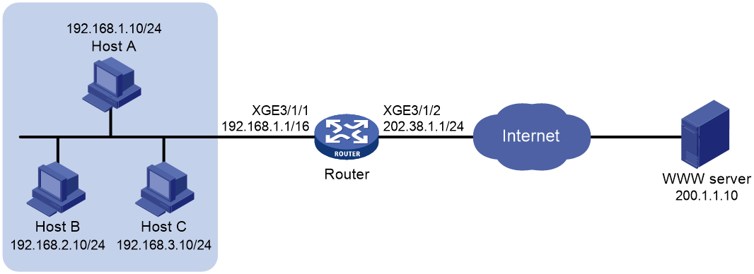
Procedure
# Specify IP addresses for the interfaces on the router. (Details not shown.)
# Configure ACL 2001 to identify packets from subnet 192.168.1.0. In this example, the packets redirected to the service card that provides NAT services require address translation. As a result, the ACL rule defined in ACL 2001 is the same as that defined in ACL 2000. You can define different ACL rules as required.
<Router> system-view
[Router] acl basic 2001
[Router-acl-ipv4-basic-2001] rule permit source 192.168.1.0 0.0.0.255
[Router-acl-ipv4-basic-2001] quit
# Configure a QoS policy to redirect packets matching ACL 2001 to the card in slot 2.
[Router] traffic classifier 1
[Router-classifier-1] if-match acl 2001
[Router-classifier-1] quit
[Router] traffic behavior 1
[Router-behavior-1] redirect slot 2
[Router-behavior-1] quit
[Router] qos policy 1
[Router-qospolicy-1] classifier 1 behavior 1
[Router-qospolicy-1] quit
[Router] interface ten-gigabitethernet 3/1/1
[Router-Ten-GigabitEthernet3/1/1] qos apply policy 1 inbound
[Router-Ten-GigabitEthernet3/1/1] quit
[Router] quit
# Configure address group 0, and add an address range from 202.38.1.2 to 202.38.1.3 to the group.
<Router> system-view
[Router] nat address-group 0
[Router-address-group-0] address 202.38.1.2 202.38.1.3
[Router-address-group-0] quit
# Configure ACL 2000 to identify packets from subnet 192.168.1.0/24.
[Router] acl basic 2000
[Router-acl-ipv4-basic-2000] rule permit source 192.168.1.0 0.0.0.255
[Router-acl-ipv4-basic-2000] quit
# Enable outbound dynamic PAT on Ten-GigabitEthernet 3/1/2. The source IP addresses of the packets permitted by the ACL rule is translated into the addresses in address group 0.
[Router] interface ten-gigabitethernet 3/1/2
[Router-Ten-GigabitEthernet3/1/2] nat outbound 2000 address-group 0
# Specify slot 2 to process NAT traffic.
[Router-Ten-GigabitEthernet3/1/2] nat service slot 2
[Router-Ten-GigabitEthernet3/1/2] quit
Verifying the configuration
# Verify that Host A can access the WWW server, while Host B cannot. (Details not shown.)
# Display all NAT configuration and statistics.
[Router] display nat all
NAT address group information:
Totally 1 NAT address groups.
Address group name/ID: 0/0
Address information:
Start address End address
202.38.1.2 202.38.1.3
NAT outbound information:
Totally 1 NAT outbound rules.
Interface: Ten-GigabitEthernet3/1/2
ACL: 2000 Address group: 0 Port-preserved: N
NO-PAT: N Reversible: N
Service card: Slot 2
Config status: Active
NAT logging:
Log enable : Disabled
Flow-begin : Disabled
Flow-end : Disabled
Flow-active : Disabled
Port-block-assign : Disabled
Port-block-withdraw : Disabled
Port-alloc-fail : Enabled
Port-block-alloc-fail : Disabled
Port-usage : Disabled
Port-block-usage : Enabled(Threshold: 40%)
NAT mapping behavior:
Mapping mode : Address and Port-Dependent
ACL : ---
Config status: Active
NAT ALG:
DNS : Disabled
FTP : Enabled
H323 : Disabled
ICMP-ERROR : Enabled
ILS : Disabled
MGCP : Disabled
NBT : Disabled
PPTP : Disabled
RTSP : Enabled
RSH : Disabled
SCCP : Disabled
SIP : Disabled
SQLNET : Disabled
TFTP : Disabled
XDMCP : Disabled
# Display NAT session information generated when Host A accesses the WWW server.
[Router] display nat session verbose
Initiator:
Source IP/port: 192.168.1.10/52992
Destination IP/port: 200.1.1.10/2048
DS-Lite tunnel peer: -
VPN instance/VLAN ID/VLL ID: -/-/-
Protocol: ICMP(1)
Inbound interface: Ten-GigabitEthernet3/1/1
Responder:
Source IP/port: 200.1.1.10/4
Destination IP/port: 202.38.1.3/0
DS-Lite tunnel peer: -
VPN instance/VLAN ID/VLL ID: -/-/-
Protocol: ICMP(1)
Inbound interface: Ten-GigabitEthernet3/1/2
State: ICMP_REPLY
Application: INVALID
Role: -
Failover group ID: -
Start time: 2012-08-15 14:53:29 TTL: 12s
Initiator->Responder: 1 packets 84 bytes
Responder->Initiator: 1 packets 84 bytes
Total sessions found: 1
Example: Configuring NAT Server for external-to-internal access
Network configuration
As shown in Figure 30, two Web servers, one FTP server and one SMTP server are in the internal network to provide services for external users. The internal network address is 10.110.0.0/16. The company has three public IP addresses from 202.38.1.1/24 to 202.38.1.3/24.
Configure the NAT Server feature to allow the external user to use public address 202.38.1.1/24 to access the internal servers.

Procedure
# Specify IP addresses for the interfaces on the router. (Details not shown.)
# Configure ACL 2001 to identify packets from subnet 10.110.10.0.
<Router> system-view
[Router] acl basic 2001
[Router-acl-ipv4-basic-2001] rule permit source 10.110.10.0 0.0.0.255
[Router-acl-ipv4-basic-2001] quit
# Configure a QoS policy to redirect packets matching ACL 2001 to the card in slot 2.
[Router] traffic classifier 1
[Router-classifier-1] if-match acl 2001
[Router-classifier-1] quit
[Router] traffic behavior 1
[Router-behavior-1] redirect slot 2
[Router-behavior-1] quit
[Router] qos policy 1
[Router-qospolicy-1] classifier 1 behavior 1
[Router-qospolicy-1] quit
[Router] interface ten-gigabitethernet 3/1/1
[Router-Ten-GigabitEthernet3/1/1] qos apply policy 1 inbound
[Router-Ten-GigabitEthernet3/1/1] quit
[Router] quit
# Enter interface view of Ten-GigabitEthernet 3/1/2.
<Router> system-view
[Router] interface ten-gigabitethernet 3/1/2
# Configure a NAT server mapping to allow external users to access the FTP server by using the address 202.38.1.1 and port 21.
[Router-Ten-GigabitEthernet3/1/2] nat server protocol tcp global 202.38.1.1 21 inside 10.110.10.3 ftp
# Configure a NAT server mapping to allow external users to access the Web server 1 by using the address 202.38.1.1 and port 80.
[Router-Ten-GigabitEthernet3/1/2] nat server protocol tcp global 202.38.1.1 80 inside 10.110.10.1 http
# Configure a NAT server mapping to allow external users to access the Web server 2 by using the address 202.38.1.1 and port 8080.
[Router-Ten-GigabitEthernet3/1/2] nat server protocol tcp global 202.38.1.1 8080 inside 10.110.10.2 http
# Configure a NAT server mapping to allow external users to access the SMTP server by using the address 202.38.1.1 and port number defined by SMTP.
[Router-Ten-GigabitEthernet3/1/2] nat server protocol tcp global 202.38.1.1 smtp inside 10.110.10.4 smtp
# Specify slot 2 to process NAT traffic.
[Router-Ten-GigabitEthernet3/1/2] nat service slot 2
[Router-Ten-GigabitEthernet3/1/2] quit
Verifying the configuration
# Verify that the host on the external network can access the internal servers by using the public addresses. (Details not shown.)
# Display all NAT configuration and statistics.
[Router] display nat all
NAT internal server information:
Totally 4 internal servers.
Interface: Ten-GigabitEthernet3/1/2
Protocol: 6(TCP)
Global IP/port: 202.38.1.1/21
Local IP/port : 10.110.10.3/21
Service card : Slot 2
Config status : Active
Interface: Ten-GigabitEthernet3/1/2
Protocol: 6(TCP)
Global IP/port: 202.38.1.1/25
Local IP/port : 10.110.10.4/25
Service card : Slot 2
Config status : Active
Interface: Ten-GigabitEthernet3/1/2
Protocol: 6(TCP)
Global IP/port: 202.38.1.1/80
Local IP/port : 10.110.10.1/80
Service card : Slot 2
Config status : Active
Interface: Ten-GigabitEthernet3/1/2
Protocol: 6(TCP)
Global IP/port: 202.38.1.1/8080
Local IP/port : 10.110.10.2/80
Service card : Slot 2
Config status : Active
NAT logging:
Log enable : Disabled
Flow-begin : Disabled
Flow-end : Disabled
Flow-active : Disabled
Port-block-assign : Disabled
Port-block-withdraw : Disabled
Port-alloc-fail : Enabled
Port-block-alloc-fail : Disabled
Port-usage : Disabled
Port-block-usage : Enabled(Threshold: 40%)
NAT mapping behavior:
Mapping mode : Address and Port-Dependent
ACL : ---
Config status: Active
NAT ALG:
DNS : Disabled
FTP : Enabled
H323 : Disabled
ICMP-ERROR : Enabled
ILS : Disabled
MGCP : Disabled
NBT : Disabled
PPTP : Disabled
RTSP : Enabled
RSH : Disabled
SCCP : Disabled
SIP : Disabled
SQLNET : Disabled
TFTP : Disabled
XDMCP : Disabled
# Display NAT session information generated when Host accesses the FTP server.
[Router] display nat session verbose
Initiator:
Source IP/port: 202.38.1.10/1694
Destination IP/port: 202.38.1.1/21
DS-Lite tunnel peer: -
VPN instance/VLAN ID/VLL ID: -/-/-
Protocol: TCP(6)
Inbound interface: Ten-GigabitEthernet3/1/2
Responder:
Source IP/port: 10.110.10.3/21
Destination IP/port: 202.38.1.10/1694
DS-Lite tunnel peer: -
VPN instance/VLAN ID/VLL ID: -/-/-
Protocol: TCP(6)
Inbound interface: Ten-GigabitEthernet3/1/1
State: TCP_ESTABLISHED
Application: FTP
Role: -
Failover group ID: -
Start time: 2012-08-15 14:53:29 TTL: 3597s
Initiator->Responder: 7 packets 308 bytes
Responder->Initiator: 5 packets 312 bytes
Total sessions found: 1
Example: Configuring NAT Server for external-to-internal access through domain name
Network configuration
As shown in Figure 31, Web server at 10.110.10.2/24 in the internal network provides services for external users. A DNS server at 10.110.10.3/24 is used to resolve the domain name of the Web server. The company has two public IP addresses: 202.38.1.2 and 202.38.1.3.
Configure NAT Server to allow external users to access the internal Web server by using the domain name.

Analysis
To meet the network configuration requirements, you must perform the following tasks:
· Configure NAT Server to map the private IP address and port of the DNS server to a public address and port. NAT Server allows the external host to access the internal DNS server for domain name resolution.
· Enable ALG for DNS and configure outbound dynamic NAT to translate the private IP address of the Web server in the payload of the DNS response packet into a public IP address.
Procedure
# Specify IP addresses for the interfaces on the router. (Details not shown.)
# Configure ACL 2001 to identify packets from subnet 10.110.10.0.
<Router> system-view
[Router] acl basic 2001
[Router-acl-ipv4-basic-2001] rule permit source 10.110.10.0 0.0.0.255
[Router-acl-ipv4-basic-2001] quit
# Configure a QoS policy to redirect packets matching ACL 2001 to the card in slot 2.
[Router] traffic classifier 1
[Router-classifier-1] if-match acl 2001
[Router-classifier-1] quit
[Router] traffic behavior 1
[Router-behavior-1] redirect slot 2
[Router-behavior-1] quit
[Router] qos policy 1
[Router-qospolicy-1] classifier 1 behavior 1
[Router-qospolicy-1] quit
[Router] interface ten-gigabitethernet 3/1/1
[Router-Ten-GigabitEthernet3/1/1] qos apply policy 1 inbound
[Router-Ten-GigabitEthernet3/1/1] quit
[Router] quit
# Enable NAT ALG for DNS.
<Router> system-view
[Router] nat alg dns
# Configure ACL 2000 to identify packets from 10.110.10.2.
[Router] acl basic 2000
[Router-acl-ipv4-basic-2000] rule permit source 10.110.10.2 0
[Router-acl-ipv4-basic-2000] quit
# Create address group 1.
[Router] nat address-group 1
# Add address 202.38.1.3 to the group.
[Router-address-group-1] address 202.38.1.3 202.38.1.3
[Router-address-group-1] quit
# Configure NAT Server on Ten-GigabitEthernet 3/1/2 to map the address 202.38.1.1 to 10.110.10.3. External users can access the internal DNS server.
[Router] interface ten-gigabitethernet 3/1/2
[Router-Ten-GigabitEthernet3/1/2] nat server protocol udp global 202.38.1.2 inside 10.110.10.3 dns
# Enable outbound NO-PAT on Ten-GigabitEthernet 3/1/2. Use the address in address group 1 to translate the private address in DNS response payload, and allow reversible NAT.
[Router-Ten-GigabitEthernet3/1/2] nat outbound 2000 address-group 1 no-pat reversible
# Specify slot 2 to process NAT traffic.
[Router-Ten-GigabitEthernet3/1/2] nat service slot 2
[Router-Ten-GigabitEthernet3/1/2] quit
Verifying the configuration
# Verify that the host on the external network can access the internal Web server by using the server's domain name. (Details not shown.)
# Display all NAT configuration and statistics.
[Router] display nat all
NAT address group information:
Totally 1 NAT address groups.
Address group name/ID: 1/1
Address information:
Start address End address
202.38.1.3 202.38.1.3
NAT outbound information:
Totally 1 NAT outbound rules.
Interface: Ten-GigabitEthernet3/1/2
ACL: 2000 Address group: 1 Port-preserved: N
NO-PAT: Y Reversible: Y
Service card: Slot 2
Config status: Active
NAT internal server information:
Totally 1 internal servers.
Interface: Ten-GigabitEthernet3/1/2
Protocol: 17(UDP)
Global IP/port: 202.38.1.2/53
Local IP/port : 10.110.10.3/53
Service card : Slot 2
Config status : Active
NAT logging:
Log enable : Disabled
Flow-begin : Disabled
Flow-end : Disabled
Flow-active : Disabled
Port-block-assign : Disabled
Port-block-withdraw : Disabled
Port-alloc-fail : Enabled
Port-block-alloc-fail : Disabled
Port-usage : Disabled
Port-block-usage : Enabled(Threshold: 40%)
NAT mapping behavior:
Mapping mode : Address and Port-Dependent
ACL : ---
Config status: Active
NAT ALG:
DNS : Enabled
FTP : Enabled
H323 : Disabled
ICMP-ERROR : Enabled
ILS : Disabled
MGCP : Disabled
NBT : Disabled
PPTP : Disabled
RTSP : Enabled
RSH : Disabled
SCCP : Disabled
SIP : Disabled
SQLNET : Disabled
TFTP : Disabled
XDMCP : Disabled
# Display NAT session information generated when Host accesses Web server.
[Router] display nat session verbose
Initiator:
Source IP/port: 200.1.1.2/1694
Destination IP/port: 202.38.1.3/8080
DS-Lite tunnel peer: -
VPN instance/VLAN ID/VLL ID: -/-/-
Protocol: TCP(6)
Inbound interface: Ten-GigabitEthernet3/1/2
Responder:
Source IP/port: 10.110.10.2/8080
Destination IP/port: 202.1.1.2/1694
DS-Lite tunnel peer: -
VPN instance/VLAN ID/VLL ID: -/-/-
Protocol: TCP(6)
Inbound interface: Ten-GigabitEthernet3/1/1
State: TCP_ESTABLISHED
Application: HTTP
Role: -
Failover group ID: -
Start time: 2012-08-15 14:53:29 TTL: 3597s
Initiator->Responder: 7 packets 308 bytes
Responder->Initiator: 5 packets 312 bytes
Total sessions found: 1
Example: Configuring NAT hairpin in C/S mode
Network configuration
As shown in Figure 32, the internal FTP server at 192.168.1.4/24 provides services for internal and external users. The private network uses two public IP addresses 202.38.1.1 and 202.38.1.2.
Configure NAT hairpin in C/S mode to allow external and internal users to access the internal FTP server by using public IP address 202.38.1.2.

Requirements analysis
To allow external hosts to access the internal FTP server by using a public IP address, configure NAT Server on the interface connected to the external network.
To allow internal hosts to access the internal FTP server by using a public IP address, perform the following tasks:
· Enable NAT hairpin on the interface connected to the internal network.
· Configure outbound NAT on the interface where the NAT server mapping is configured. The destination address is translated by matching the NAT server mapping. The source address is translated by matching the outbound NAT.
Procedure
# Specify IP addresses for the interfaces on the router. (Details not shown.)
# Configure a QoS policy on the router to redirect traffic that needs NAT to the service card. (Details not shown.)
# Configure ACL 2000 to identify packets from subnet 192.168.1.0/24.
<Router> system-view
[Router] acl basic 2000
[Router-acl-ipv4-basic-2000] rule permit source 192.168.1.0 0.0.0.255
[Router-acl-ipv4-basic-2000] quit
# Configure a NAT server mapping on Ten-GigabitEthernet 3/1/2 to map the IP address of the FTP server to a public address, allowing external users to access the internal FTP server.
[Router] interface ten-gigabitethernet 3/1/2
[Router-Ten-GigabitEthernet3/1/2] nat server protocol tcp global 202.38.1.2 inside 192.168.1.4 ftp
# Enable outbound NAT with Easy IP on Ten-GigabitEthernet 3/1/2 so that NAT translates the source addresses of the packets from internal hosts into the IP address of Ten-GigabitEthernet 3/1/2.
[Router-Ten-GigabitEthernet3/1/2] nat outbound 2000
# Specify slot 2 to process NAT traffic for Ten-GigabitEthernet 3/1/2.
[Router-Ten-GigabitEthernet3/1/2] nat service slot 2
[Router-Ten-GigabitEthernet3/1/2] quit
# Enable NAT hairpin on Ten-GigabitEthernet 3/1/1.
[Router] interface ten-gigabitethernet 3/1/1
[Router-Ten-GigabitEthernet3/1/1] nat hairpin enable
# Specify slot 2 to process NAT traffic for Ten-GigabitEthernet 3/1/1.
[Router-Ten-GigabitEthernet3/1/1] nat service slot 2
[Router-Ten-GigabitEthernet3/1/1] quit
Verifying the configuration
# Verify that both internal and external hosts can access the internal FTP server through the public address. (Details not shown.)
# Display all NAT configuration and statistics.
[Router]display nat all
NAT outbound information:
Totally 1 NAT outbound rules.
Interface: Ten-GigabitEthernet3/1/2
ACL: 2000 Address group: --- Port-preserved: N
NO-PAT: N Reversible: N
Service card: Slot 2
Config status: Active
NAT internal server information:
Totally 1 internal servers.
Interface: Ten-GigabitEthernet3/1/2
Protocol: 6(TCP)
Global IP/port: 202.38.1.2/21
Local IP/port : 192.168.1.4/21
Service card : Slot 2
Config status : Active
NAT logging:
Log enable : Disabled
Flow-begin : Disabled
Flow-end : Disabled
Flow-active : Disabled
Port-block-assign : Disabled
Port-block-withdraw : Disabled
Port-alloc-fail : Enabled
Port-block-alloc-fail : Disabled
Port-usage : Disabled
Port-block-usage : Enabled(Threshold: 40%)
NAT hairpinning:
Totally 1 interfaces enabled with NAT hairpinning.
Interface: Ten-GigabitEthernet3/1/1
Service card : Slot 2
Config status: Active
NAT mapping behavior:
Mapping mode : Address and Port-Dependent
ACL : ---
Config status: Active
NAT ALG:
DNS : Disabled
FTP : Enabled
H323 : Disabled
ICMP-ERROR : Enabled
ILS : Disabled
MGCP : Disabled
NBT : Disabled
PPTP : Disabled
RTSP : Enabled
RSH : Disabled
SCCP : Disabled
SIP : Disabled
SQLNET : Disabled
TFTP : Disabled
XDMCP : Disabled
# Display NAT session information generated when Host A accesses the FTP server.
[Router] display nat session verbose
Initiator:
Source IP/port: 192.168.1.2/1694
Destination IP/port: 202.38.1.2/21
DS-Lite tunnel peer: -
VPN instance/VLAN ID/VLL ID: -/-/-
Protocol: TCP(6)
Inbound interface: Ten-GigabitEthernet3/1/1
Responder:
Source IP/port: 192.168.1.4/21
Destination IP/port: 202.38.1.1/1025
DS-Lite tunnel peer: -
VPN instance/VLAN ID/VLL ID: -/-/-
Protocol: TCP(6)
Inbound interface: Ten-GigabitEthernet3/1/1
State: TCP_ESTABLISHED
Application: FTP
Role: -
Failover group ID: -
Start time: 2012-08-15 14:53:29 TTL: 3597s
Initiator->Responder: 7 packets 308 bytes
Responder->Initiator: 5 packets 312 bytes
Example: Configuring Twice NAT
Network configuration
As shown in Figure 33, two departments are in different VPN instances with overlapping addresses. Configure twice NAT so that Host A and Host B in different departments can access each other.
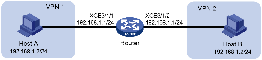
Requirements analysis
This is a typical application of twice NAT. Both the source and destination addresses of packets between the two VPNs need to be translated. Configure static NAT on both interfaces connected to the VPNs on the NAT device.
Procedure
# Specify VPN instances and IP addresses for the interfaces on the router. (Details not shown.)
# Configure IPv4 basic ACL 2001 to identify packets from subnet 192.168.1.0/24.
<Router> system-view
[Router] acl basic 2001
[Router-acl-ipv4-basic-2001] rule permit source 192.168.1.0 0.0.0.255
[Router-acl-ipv4-basic-2001] quit
# Configure traffic class user and traffic behavior nat to redirect packets matching ACL 2001 to the service card in slot 2.
[Router] traffic classifier user
[Router-classifier-user] if-match acl 2001
[Router-classifier-user] quit
[Router] traffic behavior nat
[Router-behavior-nat] redirect slot 2
[Router-behavior-nat] quit
# Create a QoS policy and associate the traffic class with the traffic behavior.
[Router] qos policy policy
[Router-qospolicy-policy] classifier user behavior nat
[Router-qospolicy-policy] quit
# Apply the QoS policy to the inbound traffic on Ten-GigabitEthernet 3/1/2.
[Router] interface ten-gigabitethernet 3/1/2
[Router-Ten-GigabitEthernet3/1/2] qos apply policy policy inbound
# Apply the QoS policy to the inbound traffic on Ten-GigabitEthernet 3/1/1.
[Router] interface ten-gigabitethernet 3/1/1
[Router-Ten-GigabitEthernet3/1/1] qos apply policy policy inbound
[Router-Ten-GigabitEthernet3/1/1] quit
[Router] quit
# Configure a static outbound NAT mapping between 192.168.1.2 in vpn 1 and 172.16.1.2 in vpn 2.
<Router> system-view
[Router] nat static outbound 192.168.1.2 vpn-instance vpn1 172.16.1.2 vpn-instance vpn2
# Configure a static outbound NAT mapping between 192.168.1.2 in vpn 2 and 172.16.2.2 in vpn 1.
[Router] nat static outbound 192.168.1.2 vpn-instance vpn2 172.16.2.2 vpn-instance vpn1
# Enable static NAT on Ten-GigabitEthernet 3/1/2.
[Router] interface ten-gigabitethernet 3/1/2
[Router-Ten-GigabitEthernet3/1/2] nat static enable
# Specify slot 2 to process NAT traffic for Ten-GigabitEthernet 3/1/2.
[Router-Ten-GigabitEthernet3/1/2] nat service slot 2
[Router-Ten-GigabitEthernet3/1/2] quit
# Enable static NAT on Ten-GigabitEthernet 3/1/1.
[Router] interface ten-gigabitethernet 3/1/1
[Router-Ten-GigabitEthernet3/1/1] nat static enable
# Specify slot 2 to process NAT traffic for Ten-GigabitEthernet 3/1/1.
[Router-Ten-GigabitEthernet3/1/1] nat service slot 2
[Router-Ten-GigabitEthernet3/1/1] quit
Verifying the configuration
# Verify that Host A and Host B can access each other. The public address for Host A is 172.16.1.2 and that for Host B is 172.16.2.2. (Details not shown.)
# Display all NAT configuration and statistics.
[Router] display nat all
Static NAT mappings:
Totally 2 outbound static NAT mappings.
IP-to-IP:
Local IP : 192.168.1.2
Global IP : 172.16.1.2
Local VPN : vpn1
Global VPN : vpn2
Config status: Active
IP-to-IP:
Local IP : 192.168.1.2
Global IP : 172.16.2.2
Local VPN : vpn2
Global VPN : vpn1
Config status: Active
Interfaces enabled with static NAT:
Totally 2 interfaces enabled with static NAT.
Interface: Ten-GigabitEthernet3/1/1
Service card : Slot 2
Config status: Active
Interface: Ten-GigabitEthernet3/1/2
Service card : Slot 2
Config status: Active
NAT logging:
Log enable : Disabled
Flow-begin : Disabled
Flow-end : Disabled
Flow-active : Disabled
Port-block-assign : Disabled
Port-block-withdraw : Disabled
Port-alloc-fail : Enabled
Port-block-alloc-fail : Disabled
Port-usage : Disabled
Port-block-usage : Enabled(Threshold: 40%)
NAT mapping behavior:
Mapping mode : Address and Port-Dependent
ACL : ---
Config status: Active
NAT ALG:
DNS : Disabled
FTP : Enabled
H323 : Disabled
ICMP-ERROR : Enabled
ILS : Disabled
MGCP : Disabled
NBT : Disabled
PPTP : Disabled
RTSP : Enabled
RSH : Disabled
SCCP : Disabled
SIP : Disabled
SQLNET : Disabled
TFTP : Disabled
XDMCP : Disabled
# Display NAT session information generated when Host A accesses Host B.
[Router] display nat session verbose
Initiator:
Source IP/port: 192.168.1.2/42496
Destination IP/port: 172.16.2.2/2048
DS-Lite tunnel peer: -
VPN instance/VLAN ID/VLL ID: vpn1/-/-
Protocol: ICMP(1)
Inbound interface: Ten-GigabitEthernet3/1/1
Responder:
Source IP/port: 192.168.1.2/42496
Destination IP/port: 172.16.1.2/0
DS-Lite tunnel peer: -
VPN instance/VLAN ID/VLL ID: vpn2/-/-
Protocol: ICMP(1)
Inbound interface: Ten-GigabitEthernet3/1/2
State: ICMP_REPLY
Application: INVALID
Role: -
Failover group ID: -
Start time: 2012-08-16 09:30:49 TTL: 27s
Initiator->Responder: 5 packets 420 bytes
Responder->Initiator: 5 packets 420 bytes
Total sessions found: 1
Example: Configuring load sharing NAT Server
Network configuration
As shown in Figure 34, three FTP servers are in the intranet to provide FTP services for external users. Configure NAT so that these external users use the address 202.38.1.1/16 to access the servers and the three FTP servers implement load sharing.

Procedure
# Specify IP addresses for the interfaces on the router. (Details not shown.)
# Configure ACL 2001 to identify packets from subnet 10.110.10.0.
<Router> system-view
[Router] acl basic 2001
[Router-acl-ipv4-basic-2001] rule permit source 10.110.10.0 0.0.0.255
[Router-acl-ipv4-basic-2001] quit
# Configure a QoS policy to redirect packets matching ACL 2001 to the card in slot 2.
[Router] traffic classifier 1
[Router-classifier-1] if-match acl 2001
[Router-classifier-1] quit
[Router] traffic behavior 1
[Router-behavior-1] redirect slot 2
[Router-behavior-1] quit
[Router] qos policy 1
[Router-qospolicy-1] classifier 1 behavior 1
[Router-qospolicy-1] quit
[Router] interface ten-gigabitethernet 3/1/1
[Router-Ten-GigabitEthernet3/1/1] qos apply policy 1 inbound
[Router-Ten-GigabitEthernet3/1/1] quit
[Router] quit
# Create NAT Server group 0, and add members to the group.
<Router> system-view
[Router] nat server-group 0
[Router-nat-server-group-0] inside ip 10.110.10.1 port 21
[Router-nat-server-group-0] inside ip 10.110.10.2 port 21
[Router-nat-server-group-0] inside ip 10.110.10.3 port 21
[Router-nat-server-group-0] quit
# Associate NAT Server group 0 with Ten-GigabitEthernet 3/1/2 so that servers in the server group can provide FTP services.
[Router] interface ten-gigabitethernet 3/1/2
[Router-Ten-GigabitEthernet3/1/2] nat server protocol tcp global 202.38.1.1 ftp inside server-group 0
# Specify slot 2 to process NAT traffic.
[Router-Ten-GigabitEthernet3/1/2] nat service slot 2
[Router-Ten-GigabitEthernet3/1/2] quit
Verifying the configuration
# Verify that external hosts can access the internal FTP server group. (Details not shown.)
# Display all NAT configuration and statistics.
[Router] display nat all
NAT server group information:
Totally 1 NAT server groups.
Group Number Inside IP Port Weight
0 10.110.10.1 21 100
10.110.10.2 21 100
10.110.10.3 21 100
NAT internal server information:
Totally 1 internal servers.
Interface: Ten-GigabitEthernet3/1/2
Protocol: 6(TCP)
Global IP/port: 202.38.1.1/21
Local IP/port : server group 0
10.110.10.1/21 (Connections: 1)
10.110.10.2/21 (Connections: 2)
10.110.10.3/21 (Connections: 2)
Service card : Slot 2
Config status : Active
NAT logging:
Log enable : Disabled
Flow-begin : Disabled
Flow-end : Disabled
Flow-active : Disabled
Port-block-assign : Disabled
Port-block-withdraw : Disabled
Port-alloc-fail : Enabled
Port-block-alloc-fail : Disabled
Port-usage : Disabled
Port-block-usage : Enabled(Threshold: 40%)
NAT mapping behavior:
Mapping mode : Address and Port-Dependent
ACL : ---
Config status: Active
NAT ALG:
DNS : Disabled
FTP : Enabled
H323 : Disabled
ICMP-ERROR : Enabled
ILS : Disabled
MGCP : Disabled
NBT : Disabled
PPTP : Disabled
RTSP : Enabled
RSH : Disabled
SCCP : Disabled
SIP : Disabled
SQLNET : Disabled
TFTP : Disabled
XDMCP : Disabled
# Display NAT session information generated when external hosts access an internal FTP server.
[Router] display nat session verbose
Initiator:
Source IP/port: 202.38.1.25/53957
Destination IP/port: 202.38.1.1/21
DS-Lite tunnel peer: -
VPN instance/VLAN ID/VLL ID: -/-/-
Protocol: TCP(6)
Inbound interface: Ten-GigabitEthernet3/1/2
Responder:
Source IP/port: 10.110.10.3/21
Destination IP/port: 202.38.1.25/53957
DS-Lite tunnel peer: -
VPN instance/VLAN ID/VLL ID: -/-/-
Protocol: TCP(6)
Inbound interface: Ten-GigabitEthernet3/1/1
State: TCP_ESTABLISHED
Application: FTP
Role: -
Failover group ID: -
Start time: 2012-08-16 11:06:07 TTL: 26s
Initiator->Responder: 1 packets 60 bytes
Responder->Initiator: 2 packets 120 bytes
Total sessions found: 1
Example: Configuring NAT DNS mapping
Network configuration
As shown in Figure 35, the internal Web server at 10.110.10.1/16 and FTP server at 10.110.10.2/16 provide services for external user. The company has three public addresses 202.38.1.1 through 202.38.1.3. The DNS server at 202.38.1.4 is on the external network.
Configure NAT so that:
· The public IP address 202.38.1.2 is used by external users to access the Web and FTP servers.
· External users can use the public address or domain name of internal servers to access them.
· Internal users can access the internal servers by using their domain names.

Requirements analysis
To meet the network requirements, perform the following tasks:
· Configure NAT Server by mapping the public IP addresses and port numbers of the internal servers to a public address and port numbers so that external users can access the internal servers.
· Configure NAT DNS mapping and ALG so that the public IP address of the internal server in the payload of the DNS response packet can be translated to the private IP address.
Procedure
# Specify IP addresses for the interfaces on the router. (Details not shown.)
# Configure ACL 2001 to identify packets from subnet 10.110.10.0.
<Router> system-view
[Router] acl basic 2001
[Router-acl-ipv4-basic-2001] rule permit source 10.110.10.0 0.0.0.255
[Router-acl-ipv4-basic-2001] quit
# Configure a QoS policy to redirect packets matching ACL 2001 to the card in slot 2.
[Router] traffic classifier 1
[Router-classifier-1] if-match acl 2001
[Router-classifier-1] quit
[Router] traffic behavior 1
[Router-behavior-1] redirect slot 2
[Router-behavior-1] quit
[Router] qos policy 1
[Router-qospolicy-1] classifier 1 behavior 1
[Router-qospolicy-1] quit
[Router] interface ten-gigabitethernet 3/1/1
[Router-Ten-GigabitEthernet3/1/1] qos apply policy 1 inbound
[Router-Ten-GigabitEthernet3/1/1] quit
[Router] quit
# Enable NAT ALG for DNS.
<Router> system-view
[Router] nat alg dns
# Enter interface view of Ten-GigabitEthernet 3/1/2.
[Router] interface ten-gigabitethernet 3/1/2
# Configure NAT Server to allow external hosts to access the internal Web server by using the address 202.38.1.2.
[Router-Ten-GigabitEthernet3/1/2] nat server protocol tcp global 202.38.1.2 inside 10.110.10.1 http
# Configure NAT Server to allow external hosts to access the internal FTP server by using the address 202.38.1.2.
[Router-Ten-GigabitEthernet3/1/2] nat server protocol tcp global 202.38.1.2 inside 10.110.10.2 ftp
# Enable outbound NAT with Easy IP on Ten-GigabitEthernet 3/1/2.
[Router-Ten-GigabitEthernet3/1/2] nat outbound
# Specify slot 2 to process NAT traffic.
[Router-Ten-GigabitEthernet3/1/2] nat service slot 2
[Router-Ten-GigabitEthernet3/1/2] quit
# Configure two NAT DNS mapping entries by mapping the domain name www.server.com of the Web server to 202.38.1.2, and ftp.server.com of the FTP server to 202.38.1.2.
[Router] nat dns-map domain www.server.com protocol tcp ip 202.38.1.2 port http
[Router] nat dns-map domain ftp.server.com protocol tcp ip 202.38.1.2 port ftp
[Router] quit
Verifying the configuration
# Verify that both internal and external hosts can access the internal servers by using domain names. (Details not shown.)
# Display all NAT configuration and statistics.
[Router] display nat all
NAT outbound information:
Totally 1 NAT outbound rules.
Interface: Ten-GigabitEthernet3/1/2
ACL: --- Address group: --- Port-preserved: N
NO-PAT: N Reversible: N
Service card: Slot 2
Config status: Active
NAT internal server information:
Totally 2 internal servers.
Interface: Ten-GigabitEthernet3/1/2
Protocol: 6(TCP)
Global IP/port: 202.38.1.2/21
Local IP/port : 10.110.10.2/21
Service card : Slot 2
Config status : Active
Interface: Ten-GigabitEthernet3/1/2
Protocol: 6(TCP)
Global IP/port: 202.38.1.2/80
Local IP/port : 10.110.10.1/80
Service card : Slot 2
Config status : Active
NAT DNS mapping information:
Totally 2 NAT DNS mappings.
Domain name: ftp.server.com
Global IP : 202.38.1.2
Global port: 21
Protocol : TCP(6)
Config status: Active
Domain name: www.server.com
Global IP : 202.38.1.2
Global port: 80
Protocol : TCP(6)
Config status: Active
NAT logging:
Log enable : Disabled
Flow-begin : Disabled
Flow-end : Disabled
Flow-active : Disabled
Port-block-assign : Disabled
Port-block-withdraw : Disabled
Port-alloc-fail : Enabled
Port-block-alloc-fail : Disabled
Port-usage : Disabled
Port-block-usage : Enabled(Threshold: 40%)
NAT mapping behavior:
Mapping mode: Address and Port-Dependent
ACL : ---
Config status: Active
NAT ALG:
DNS : Enabled
FTP : Enabled
H323 : Disabled
ICMP-ERROR : Enabled
ILS : Disabled
MGCP : Disabled
NBT : Disabled
PPTP : Disabled
RTSP : Enabled
RSH : Disabled
SCCP : Disabled
SIP : Disabled
SQLNET : Disabled
TFTP : Disabled
XDMCP : Disabled
Example: Configuring NAT log export to the information center
Network configuration
As shown in Figure 36, configure NAT on the device for the internal host to access the Internet. Configure NAT logging on the device and configure the device to export the NAT logs to the information center. The NAT logs in the information center are used for monitoring the internal host.

Prerequisites
Assign IP addresses to interfaces on the device and make sure the device and the host can reach each other.
Procedure
# Specify the information center as the destination for flow log export.
<Device> system-view
[Device] userlog flow syslog
# Enable NAT logging.
[Device] nat log enable
# Enable logging for NAT session establishment events.
[Device] nat log flow-begin
# Enable logging for NAT session removal events.
[Device] nat log flow-end
# Enable logging for active NAT flows and set the logging interval to 10 minutes.
[Device] nat log flow-active 10
[Device] quit
Verifying the configuration
# Display the internal host's access records in the log buffer.
<Device> dir
Directory of cf:/
38 -rw- 141 Aug 07 2015 17:54:43 ifindex.dat
39 drw- - May 20 2015 14:36:20 logfile
249852 KB total (232072 KB free)
File system type of cf: FAT32
<Device> cd logfile
<Device> dir
<Device> more logfile.log
…
%Aug 10 20:06:30:182 2015 Device NAT/6/NAT_FLOW: Protocol(1001)=ICMP;SrcIPAd
dr(1003)=10.110.10.8;SrcPort(1004)=259;NatSrcIPAddr(1005)=202.38.1.100;NatSrcPor
t(1006)=0;DstIPAddr(1007)=202.38.1.2;DstPort(1008)=2048;NatDstIPAddr(1009)=202.3
8.1.2;NatDstPort(1010)=259;InitPktCount(1044)=0;InitByteCount(1046)=0;RplyPktCou
nt(1045)=0;RplyByteCount(1047)=0;RcvVPNInstance(1042)=;SndVPNInstance(1043)=;Rcv
DSLiteTunnelPeer(1040)=;SndDSLiteTunnelPeer(1041)=;BeginTime_e(1013)=08102015200
630; EndTime_e(1014)=08102015200700;Event(1048)=(8)Session created;
…
Table 4 Command output
|
Field |
Description |
|
Protocol(1001)=ICMP |
Protocol type. |
|
SrcIPAddr(1003)=10.110.10.8 |
Source IP address before NAT. |
|
SrcPort(1004)=259 |
Source TCP or UDP port before NAT. |
|
NatSrcIPAddr(1005)=202.38.1.100 |
Source IP address after NAT. |
|
NatSrcPort(1006)=0 |
Source TCP or UDP port after NAT. |
|
DstIPAddr(1007)=202.38.1.2 |
Destination IP address before NAT. |
|
DstPort(1008)=2048 |
Destination TCP or UDP port before NAT. |
|
NatDstIPAddr(1009)=202.38.1.2 |
Destination IP address after NAT. |
|
NatDstPort(1010)=259 |
Destination TCP or UDP port after NAT. |
|
BeginTime_e(1013)=08102015200630 |
Start time of the flow, in the MMDDYYYYHHMMSS format. |
|
EndTime_e(1014)=08102015200700 |
End time of the flow, in the MMDDYYYYHHMMSS format. |
Example: Configuring NAT log export to the log server
Network configuration
As shown in Figure 37, configure the device to export the NAT logs to the log server. The NAT logs in the log server are used for monitoring the internal user.

Prerequisites
Assign IP addresses to interfaces on the device. Make sure the routes between the device and the user and between the device and the log server are reachable.
Procedure
# Enable NAT logging.
<Device> system-view
[Device] nat log enable
# Enable logging for NAT session establishment events.
[Device] nat log flow-begin
# Enable logging for NAT session removal events.
[Device] nat log flow-end
# Enable logging for active NAT flows and set the logging interval to 10 minutes.
[Device] nat log flow-active 10
# Set the flow log version to 3.0.
[Device] userlog flow export version 3
# Export flow log entries to port 2000 on the log host at 1.2.3.6.
[Device] userlog flow export host 1.2.3.6 port 2000
# Specify 2.2.2.2 as the source IP address for flow log packets.
[Device] userlog flow export source-ip 2.2.2.2
[Device] quit
Verifying the configuration
# Display the flow log configuration and statistics.
<Device> display userlog export
Flow:
Export flow log as UDP Packet.
Version: 3.0
Source ipv4 address: 2.2.2.2
Source ipv6 address:
Log load balance function: Disabled
Local time stamp: Disabled
Number of log hosts: 1
Log host 1:
Host/Port: 1.2.3.6/2000
Total logs/UDP packets exported: 112/87
NAT configuration examples (CGN application scenarios)
|
|
NOTE: In the following configuration examples, the nodes assigned the failover group by the bind command are all CGN cards. The slot numbers in the examples are for illustration only. |
Example: Configuring outbound one-to-one static NAT
Network configuration
Configure static NAT to allow the host at 10.110.10.8/24 to access the Internet.
Figure 38 Network diagram

Procedure
# Specify IP addresses for the interfaces on the router. (Details not shown.)
# Specify the card in the specified slot as the primary node in failover group cgn.
<Router> system-view
[Router] failover group cgn id 1
[Router-failover-group-cgn] bind slot 2 primary
[Router-failover-group-cgn] quit
# Configure a one-to-one static NAT mapping between the private address 10.110.10.8 and the public address 202.38.1.100.
[Router] nat static outbound 10.110.10.8 202.38.1.100 failover-group cgn
# Configure ACL 2000 to identify packets from subnet 10.110.10.0/24 to pass through.
[Router] acl basic 2000
[Router-acl-ipv4-basic-2000] rule permit source 10.110.10.0 0.0.0.255
[Router-acl-ipv4-basic-2000] quit
# Configure traffic class cgn and traffic behavior cgn to redirect packets matching ACL 2000 to failover group cgn.
[Router] traffic classifier cgn
[Router-classifier-cgn] if-match acl 2000
[Router-classifier-cgn] quit
[Router] traffic behavior cgn
[Router-behavior-cgn] redirect failover-group cgn
[Router-behavior-cgn] quit
# Configure a QoS policy and associate the traffic class with the traffic behavior.
[Router] qos policy cgn
[Router-qospolicy-cgn] classifier cgn behavior cgn
[Router-qospolicy-cgn] quit
# Apply the QoS policy to the inbound traffic on Ten-GigabitEthernet 3/1/1.
[Router] interface ten-gigabitethernet 3/1/1
[Router-Ten-GigabitEthernet3/1/1] qos apply policy cgn inbound
[Router-Ten-GigabitEthernet3/1/1] quit
# Enable static NAT on Ten-GigabitEthernet 3/1/2.
[Router] interface ten-gigabitethernet 3/1/2
[Router-Ten-GigabitEthernet3/1/2] nat static enable
[Router-Ten-GigabitEthernet3/1/2] quit
# Configure a failover group to process session-based services. Only sessions that match ACL 2000 are assigned failover group IDs.
[Router] session service-location acl 2000 failover-group cgn
Verifying the configuration
# Verify that the host at 10.110.10.8/24 can access the server on the Internet. (Details not shown.)
# Display static NAT configuration.
[Router] display nat static
Static NAT mappings:
Totally 1 outbound static NAT mappings.
IP-to-IP:
Local IP : 10.110.10.8
Global IP : 202.38.1.100
Failover group name: cgn
Config status: Active
Interfaces enabled with static NAT:
Totally 1 interfaces enabled with static NAT.
Interface: Ten-GigabitEthernet3/1/2
Config status: Active
# Display NAT session information.
[Router] display nat session slot 2 verbose
Slot 2:
Initiator:
Source IP/port: 10.110.10.8/1024
Destination IP/port: 202.38.1.111/1025
DS-Lite tunnel peer: -
VPN instance/VLAN ID/Inline ID: -/-/-
Protocol: UDP(17)
Inbound interface: Ten-GigabitEthernet3/1/1
Responder:
Source IP/port: 202.38.1.111/1025
Destination IP/port: 202.38.1.100/1024
DS-Lite tunnel peer: -
VPN instance/VLAN ID/Inline ID: -/-/-
Protocol: UDP(17)
Inbound interface: Ten-GigabitEthernet3/1/2
State: UDP_READY
Application: OTHER
Role: Master
Failover group ID: 1
Start time: 2015-05-29 18:49:37
Initiator->Responder: 0 packets 0 bytes
Responder->Initiator: 0 packets 0 bytes
Total sessions found: 1
Example: Configuring outbound dynamic NAT (non-overlapping addresses)
Network configuration
As shown in Figure 39, a company has a private address 192.168.0.0/16 and two public IP addresses 202.38.1.2 and 202.38.1.3. Configure outbound dynamic NAT to allow only internal users on subnet 192.168.1.0/24 to access the Internet.

Procedure
# Specify IP addresses for the interfaces on the router. (Details not shown.)
# Specify the card in the specified slot as the primary node in failover group cgn.
<Router> system-view
[Router] failover group cgn id 1
[Router-failover-group-cgn] bind slot 2 primary
[Router-failover-group-cgn] quit
# Configure address group 0, add an address range from 202.38.1.2 to 202.38.1.3, and specify failover group cgn for address group 0.
[Router] nat address-group 0
[Router-address-group-0] address 202.38.1.2 202.38.1.3
[Router-address-group-0] failover-group cgn
[Router-address-group-0] quit
# Configure ACL 2000 to identify packets from subnet 192.168.1.0/24.
[Router] acl basic 2000
[Router-acl-ipv4-basic-2000] rule permit source 192.168.1.0 0.0.0.255
[Router-acl-ipv4-basic-2000] quit
# Configure traffic class cgn and traffic behavior cgn to redirect packets matching ACL 2000 to failover group cgn.
[Router] traffic classifier cgn
[Router-classifier-cgn] if-match acl 2000
[Router-classifier-cgn] quit
[Router] traffic behavior cgn
[Router-behavior-cgn] redirect failover-group cgn
[Router-behavior-cgn] quit
# Configure a QoS policy and associate the traffic class with the traffic behavior.
[Router] qos policy cgn
[Router-qospolicy-cgn] classifier cgn behavior cgn
[Router-qospolicy-cgn] quit
# Apply the QoS policy to the outbound traffic on Ten-GigabitEthernet 3/1/1.
[Router] interface ten-gigabitethernet 3/1/1
[Router-Ten-GigabitEthernet3/1/1] qos apply policy cgn inbound
[Router-Ten-GigabitEthernet3/1/1] quit
# Enable outbound dynamic PAT on Ten-GigabitEthernet 3/1/2. The source IP addresses of the packets permitted by ACL 2000 are translated into the addresses in address group 0.
[Router] interface ten-gigabitethernet 3/1/2
[Router-Ten-GigabitEthernet3/1/2] nat outbound 2000 address-group 0
[Router-Ten-GigabitEthernet3/1/2] quit
# Configure a failover group to process session-based services. Only sessions that match ACL 2000 are assigned failover group IDs.
[Router] session service-location acl 2000 failover-group cgn
Verifying the configuration
# Verify that Host A can access the WWW server and Host B cannot. (Details not shown.)
# Display all NAT configuration information.
[Router] display nat all
NAT address group information:
Totally 1 NAT address groups.
Address group name/ID: 0/0
Failover group name: cgn
Address information:
Start address End address
202.38.1.2 202.38.1.3
NAT outbound information:
Totally 1 NAT outbound rules.
Interface: Ten-GigabitEthernet3/1/2
ACL: 2000 Address group: 0 Port-preserved: N
NO-PAT: N Reversible: N
Config status: Active
NAT logging:
Log enable : Disabled
Flow-begin : Disabled
Flow-end : Disabled
Flow-active : Disabled
Port-block-assign : Disabled
Port-block-withdraw : Disabled
Port-alloc-fail : Enabled
Port-block-alloc-fail : Disabled
Port-usage : Disabled
Port-block-usage : Enabled(Threshold: 40%)
Mapping mode : Connection-dependent
NAT ALG:
DNS : Disabled
FTP : Enabled
H323 : Disabled
ICMP-ERROR : Enabled
ILS : Disabled
MGCP : Disabled
NBT : Disabled
PPTP : Disabled
RTSP : Enabled
RSH : Disabled
SCCP : Disabled
SIP : Disabled
SQLNET : Disabled
TFTP : Disabled
XDMCP : Disabled
# Verify that Host A access to the WWW server generates NAT sessions.
[Router] display nat session slot 2 verbose
slot 2:
Initiator:
Source IP/port: 192.168.1.10/52992
Destination IP/port: 200.1.1.10/2048
DS-Lite tunnel peer: -
VPN instance/VLAN ID/VLL ID: -/-/-
Protocol: ICMP(1)
Inbound interface: Ten-GigabitEthernet3/1/1
Responder:
Source IP/port: 200.1.1.10/4
Destination IP/port: 202.38.1.3/0
DS-Lite tunnel peer: -
VPN instance/VLAN ID/VLL ID: -/-/-
Protocol: ICMP(1)
Inbound interface: Ten-GigabitEthernet3/1/2
State: ICMP_REPLY
Application: INVALID
Role: Master
Failover group ID: 1
Start time: 2012-08-15 14:53:29
Initiator->Responder: 1 packets 84 bytes
Responder->Initiator: 1 packets 84 bytes
Total sessions found: 1
Example: Configuring NAT static port block mapping
Network configuration
As shown in Figure 40, configure NAT static port block mapping to allow users at private IP addresses 10.110.10.1 to 10.110.10.10 to use public IP address 202.38.1.100. Configure the port range as 10001 to 15000, and set the port block size to 500.

Procedure
# Specify IP addresses for the interfaces on the router. (Details not shown.)
# Specify the card in the specified slot as the primary node in failover group cgn.
<Router> system-view
[Router] failover group cgn id 1
[Router-failover-group-cgn] bind slot 2 primary
[Router-failover-group-cgn] quit
# Create NAT port block group 1.
[Router] nat port-block-group 1
# Specify failover group cgn for NAT port block group 1.
[Router-port-block-group-1] failover-group cgn
# Add the private IP addresses from 10.110.10.1 to 10.110.10.10 to the port block group.
[Router-port-block-group-1] local-ip-address 10.110.10.1 10.110.10.10
# Add the public IP address 202.38.1.100 to the port block group.
[Router-port-block-group-1] global-ip-pool 202.38.1.100 202.38.1.100
# Set the port block size to 500.
[Router-port-block-group-1] block-size 500
# Configure the port range as 10001 to 15000.
[Router-port-block-group-1] port-range 10001 15000
[Router-port-block-group-1] quit
# Configure ACL 2000 identify packets from subnet 10.110.10.0/24.
[Router] acl basic 2000
[Router-acl-ipv4-basic-2000] rule permit source 10.110.10.0 0.0.0.255
[Router-acl-ipv4-basic-2000] quit
# Configure traffic class cgn and traffic behavior cgn to redirect packets matching ACL 2000 to failover group cgn.
[Router] traffic classifier cgn
[Router-classifier-cgn] if-match acl 2000
[Router-classifier-cgn] quit
[Router] traffic behavior cgn
[Router-behavior-cgn] redirect failover-group cgn
[Router-behavior-cgn] quit
# Configure a QoS policy and associate the traffic class with the traffic behavior.
[Router] qos policy cgn
[Router-qospolicy-cgn] classifier cgn behavior cgn
[Router-qospolicy-cgn] quit
# Apply the QoS policy to the inbound traffic on Ten-GigabitEthernet 3/1/1.
[Router] interface ten-gigabitethernet 3/1/1
[Router-Ten-GigabitEthernet3/1/1] qos apply policy cgn inbound
[Router-Ten-GigabitEthernet3/1/1] quit
# Apply the port block group 1 to the outbound direction of Ten-GigabitEthernet 3/1/2.
[Router] interface ten-gigabitethernet 3/1/2
[Router-Ten-GigabitEthernet3/1/2] nat outbound port-block-group 1
[Router-Ten-GigabitEthernet3/1/2] quit
# Configure a failover group to process session-based services. Only sessions that match ACL 2000 are assigned failover group IDs.
[Router] session service-location acl 2000 failover-group cgn
# Enable flow-triggered port block assignment.
[Router] nat port-block flow-trigger enable
Verifying the configuration
# Verify that users at the private IP addresses can access the Internet. (Details not shown.)
# Display all NAT configuration and statistics.
[Router] display nat all
NAT logging:
Log enable : Disabled
Flow-begin : Disabled
Flow-end : Disabled
Flow-active : Disabled
Port-block-assign : Disabled
Port-block-withdraw : Disabled
Port-alloc-fail : Enabled
Port-block-alloc-fail : Disabled
Port-usage : Disabled
Port-block-usage : Enabled(Threshold: 40%)
Mapping mode : Connection-dependent
NAT ALG:
DNS : Disabled
FTP : Enabled
H323 : Disabled
ICMP-ERROR : Enabled
ILS : Disabled
MGCP : Disabled
NBT : Disabled
PPTP : Disabled
RTSP : Enabled
RSH : Disabled
SCCP : Disabled
SIP : Disabled
SQLNET : Disabled
TFTP : Disabled
XDMCP : Disabled
NAT port block group information:
Totally 1 NAT port block groups.
Port block group 1:
Port range: 10001-15000
Block size: 500
Failover group name: cgn
Local IP address information:
Start address End address VPN instance
10.110.10.1 10.110.10.10 ---
Global IP pool information:
Start address End address
202.38.1.100 202.38.1.100
NAT outbound port block group information:
Totally 1 outbound port block group items.
Interface: Ten-GigabitEthernet3/1/2
Port-block-group: 1
Config status : Active
# Display NAT444 static port block mappings.
[Router] display nat port-block static slot 2
Slot 2:
Local VPN Local IP Global IP Port block Connections Extend
--- 10.110.10.1 202.38.1.100 10001-10500 2 ---
--- 10.110.10.2 202.38.1.100 10501-11000 0 ---
--- 10.110.10.3 202.38.1.100 11001-11500 0 ---
--- 10.110.10.4 202.38.1.100 11501-12000 0 ---
--- 10.110.10.5 202.38.1.100 12001-12500 1 ---
--- 10.110.10.6 202.38.1.100 12501-13000 0 ---
--- 10.110.10.7 202.38.1.100 13001-13500 0 ---
--- 10.110.10.8 202.38.1.100 13501-14000 0 ---
--- 10.110.10.9 202.38.1.100 14001-14500 0 ---
--- 10.110.10.10 202.38.1.100 14501-15000 0 ---
Total mappings found: 10
Example: Configuring NAT dynamic port block mapping
Network configuration
As shown in Figure 41, a company uses private IP address on network 192.168.0.0/16 and public IP addresses 202.38.1.2 and 202.38.1.3. Configure NAT dynamic port block mapping to meet the following requirements:
· Only users on subnet 192.168.1.0/24 can use public IP addresses 202.38.1.2 and 202.38.1.3 to access the Internet.
· The port range for the public IP addresses is 1024 to 65535.
· The port block size is 300.
· If the ports in the assigned port block are all used, extend another port block for users.

Procedure
# Specify IP addresses for the interfaces on the router. (Details not shown.)
# Specify the card in the specified slot as the primary node in failover group cgn.
<Router> system-view
[Router] failover group cgn id 1
[Router-failover-group-cgn] bind slot 2 primary
[Router-failover-group-cgn] quit
# Create public address group 0.
[Router] nat address-group 0
[Router-address-group-0] failover-group cgn
# Add the public IP addresses 202.38.1.2 and 202.38.1.3 to the NAT address group.
[Router-address-group-0] address 202.38.1.2 202.38.1.3
# Configure the port range as 1024 to 65535.
[Router-address-group-0] port-range 1024 65535
# Set the port block size to 300 and the extended port block number to 1.
[Router-address-group-0] port-block block-size 300 extended-block-number 1
[Router-address-group-0] quit
# Configure an ACL to identify packets from subnet 192.168.1.0/24.
[Router] acl basic 2000
[Router-acl-ipv4-basic-2000] rule permit source 192.168.1.0 0.0.0.255
[Router-acl-ipv4-basic-2000] quit
# Configure traffic class cgn and traffic behavior cgn to redirect packets matching ACL 2000 to failover group cgn.
[Router] traffic classifier cgn
[Router-classifier-cgn] if-match acl 2000
[Router-classifier-cgn] quit
[Router] traffic behavior cgn
[Router-behavior-cgn] redirect failover-group cgn
[Router-behavior-cgn] quit
# Configure a QoS policy and associate the traffic class with the traffic behavior.
[Router] qos policy cgn
[Router-qospolicy-cgn] classifier cgn behavior cgn
[Router-qospolicy-cgn] quit
# Apply the QoS policy to the inbound traffic on Ten-GigabitEthernet 3/1/1.
[Router] interface ten-gigabitethernet 3/1/1
[Router-Ten-GigabitEthernet3/1/1] qos apply policy cgn inbound
[Router-Ten-GigabitEthernet3/1/1] quit
# Enable outbound NAT on Ten-GigabitEthernet 3/1/2.
[Router] interface ten-gigabitethernet 3/1/2
[Router-Ten-GigabitEthernet3/1/2] nat outbound 2000 address-group 0
[Router-Ten-GigabitEthernet3/1/2] quit
# Configure a failover group to process session-based services. Only sessions that match ACL 2000 are assigned failover group IDs.
[Router] session service-location acl 2000 failover-group cgn
# Enable flow-triggered port block assignment.
[Router] nat port-block flow-trigger enable
Verifying the configuration
# Verify that Host A can access external servers, but Host B and Host C cannot. (Details not shown.)
# Display all NAT configuration.
[Router] display nat all
NAT address group information:
Totally 1 NAT address groups.
Address group name/ID: 0/0
Port range: 1024-65535
Port block size: 300
Extended block number: 1
Failover group name: cgn
Address information:
Start address End address
202.38.1.2 202.38.1.3
NAT outbound information:
Totally 1 NAT outbound rules.
Interface: Ten-GigabitEthernet3/1/2
ACL: 2000 Address group: 0 Port-preserved: N
NO-PAT: N Reversible: N
Config status: Active
NAT logging:
Log enable : Disabled
Flow-begin : Disabled
Flow-end : Disabled
Flow-active : Disabled
Port-block-assign : Disabled
Port-block-withdraw : Disabled
Port-alloc-fail : Enabled
Port-block-alloc-fail : Disabled
Port-usage : Disabled
Port-block-usage : Enabled(Threshold: 40%)
Mapping mode : Connection-dependent
NAT ALG:
DNS : Disabled
FTP : Enabled
H323 : Disabled
ICMP-ERROR : Enabled
ILS : Disabled
MGCP : Disabled
NBT : Disabled
PPTP : Disabled
RTSP : Enabled
RSH : Disabled
SCCP : Disabled
SIP : Disabled
SQLNET : Disabled
TFTP : Disabled
XDMCP : Disabled
# Display NAT statistics.
[Router] display nat statistics slot 2
Slot 2:
Total session entries: 0
Total EIM entries: 0
Total inbound NO-PAT entries: 0
Total outbound NO-PAT entries: 0
Total static port block entries: 0
Total dynamic port block entries: 430
Active static port block entries: 0
Active dynamic port block entries: 1
Total PAT entries: 0
Example: Configuring DS-Lite B4 address translation
Network configuration
As shown in Figure 42, configure DS-Lite tunneling and NAT to allow the DS-Lite host to access the IPv4 network over the IPv6 network.

Procedure
1. Configure the AFTR:
# Specify an IPv4 address for Ten-GigabitEthernet 3/1/1.
<Router> system-view
[Router] interface ten-gigabitethernet 3/1/1
[Router-Ten-GigabitEthernet3/1/1] ip address 20.1.1.1 24
[Router-Ten-GigabitEthernet3/1/1] quit
# Specify an IPv6 address for Ten-GigabitEthernet 3/1/2.
[Router] interface ten-gigabitethernet 3/1/2
[Router-Ten-GigabitEthernet3/1/2] ipv6 address 1::2 64
[Router-Ten-GigabitEthernet3/1/2] quit
# Create a tunnel interface on the AFTR.
[Router] interface tunnel 2 mode ds-lite-aftr
# Specify an IP address for the tunnel interface.
[Router-Tunnel2] ip address 30.1.2.2 255.255.255.0
# Specify Ten-GigabitEthernet 3/1/2 as the source interface for the tunnel.
[Router-Tunnel2] source ten-gigabitethernet 3/1/2
[Router-Tunnel2] quit
# Enable DS-Lite tunneling on Ten-GigabitEthernet 3/1/1.
[Router] interface ten-gigabitethernet 3/1/1
[Router-Ten-GigabitEthernet3/1/1] ds-lite enable
[Router-Ten-GigabitEthernet3/1/1] quit
# Specify the card in the specified slot as the primary node in failover group cgn.
[Router] failover group cgn id 1
[Router-failover-group-cgn] bind slot 2 primary
[Router-failover-group-cgn] quit
# Create public address group 0.
[Router] nat address-group 0
[Router-address-group-0] failover-group cgn
# Add public IP addresses 20.1.1.11 and 20.1.1.12 to the NAT address group.
[Router-address-group-0] address 20.1.1.11 20.1.1.12
# Configure the port range as 1024 to 65535.
[Router-address-group-0] port-range 1024 65535
# Set the port block size to 300.
[Router-address-group-0] port-block block-size 300
[Router-address-group-0] quit
# Configure an IPv6 ACL to identify packets from subnet 1::/64.
[Router] acl ipv6 basic 2100
[Router-acl-ipv4-basic-2100] rule permit source 1::/64
[Router-acl-ipv4-basic-2100] quit
# Configure traffic class cgn and traffic behavior cgn to redirect packets matching IPv6 ACL 2100 to failover group cgn.
[Router] traffic classifier cgn
[Router-classifier-cgn] if-match acl ipv6 2100
[Router-classifier-cgn] quit
[Router] traffic behavior cgn
[Router-behavior-cgn] redirect failover-group cgn
[Router-behavior-cgn] quit
# Configure a QoS policy and associate the traffic class with the traffic behavior.
[Router] qos policy cgn
[Router-qospolicy-cgn] classifier cgn behavior cgn
[Router-qospolicy-cgn] quit
# Apply the QoS policy to the inbound traffic on Ten-GigabitEthernet 3/1/2.
[Router] interface ten-gigabitethernet 3/1/2
[Router-Ten-GigabitEthernet3/1/2] qos apply policy cgn inbound
[Router-Ten-GigabitEthernet3/1/2] quit
# Configure DS-Lite B4 address translation on Ten-GigabitEthernet 3/1/1.
[Router] interface ten-gigabitethernet 3/1/1
[Router-Ten-GigabitEthernet3/1/1] nat outbound ds-lite-b4 2100 address-group 0
[Router-Ten-GigabitEthernet3/1/1] quit
# Configure a failover group to process session-based services. Only sessions that match IPv6 ACL 2100 are assigned failover group IDs.
[Router] session service-location acl ipv6 2100 failover-group cgn
# Enable flow-triggered port block assignment.
[Router] nat port-block flow-trigger enable
2. Configure the DS-Lite host:
# Configure the IPv4 and IPv6 addresses of the DS-Lite host as 10.0.0.1 and 1::1/64. (Details not shown.)
# Configure a static route to the destination IPv4 network. (Details not shown.)
Verifying the configuration
# Use the display interface tunnel command to verify that the tunnel interface is up on the AFTR. (Details not shown.)
# Verify that the DS-Lite host can ping the IPv4 application server.
C:\> ping 20.1.1.2
Pinging 20.1.1.2 with 32 bytes of data:
Reply from 20.1.1.2: bytes=32 time=51ms TTL=255
Reply from 20.1.1.2: bytes=32 time=44ms TTL=255
Reply from 20.1.1.2: bytes=32 time=1ms TTL=255
Reply from 20.1.1.2: bytes=32 time=1ms TTL=255
Ping statistics for 20.1.1.2:
Packets: Sent = 4, Received = 4, Lost = 0 (0% loss),
Approximate round trip times in milli-seconds:
Minimum = 1ms, Maximum = 51ms, Average = 24ms
# Verify that the DS-Lite B4 address translation configuration is correct.
[Router] display nat outbound
NAT outbound information:
Totally 1 NAT outbound rules.
Interface: Ten-GigabitEthernet3/1/1
DS-Lite B4 ACL: 2100 Address group: 0 Port-preserved: N
NO-PAT: N Reversible: N
Config status: Active
# Verify that the DS-Lite B4 address translation configuration takes effect by checking the port block assignment.
[Router] display nat statistics slot 2
Slot 2:
Total session entries: 0
Total EIM entries: 0
Total inbound NO-PAT entries: 0
Total outbound NO-PAT entries: 0
Total static port block entries: 0
Total dynamic port block entries: 430
Active static port block entries: 0
Active dynamic port block entries: 1
Total PAT entries: 0
# Verify that a NAT444 port block mapping has been created for the DS-Lite host.
[Router] display nat port-block dynamic ds-lite-b4 slot 2
Slot 2:
Local VPN DS-Lite B4 addr Global IP Port block Connections Extend
--- 1::1 20.1.1.11 1024-1323 1 ---
Total mappings found: 1
Example: Configuring intra-device hot backup for NAT and BRAS unification
Network configuration
As shown in Figure 43, the host, a PPPoE client, is connected to the Internet through the router. The router acts as the BRAS device, provides NAT services through CGN cards, and provides intra-device CGN backup through a failover group. Configure PPPoE server and NAT on the router to meet the following requirements:
· The PPPoE server cooperates with the RADIUS server to authenticate the host by using CHAP, and assigns a private IP address to the host.
· The PPPoE server uses shared key expert for secure RADIUS communication, and sends usernames with domain names to the RADIUS server.
· NAT cooperates with BRAS. NAT assigns a public IP address and a port block after the host passes authentication and obtains a private IP address.
· CGN 1 and CGN 2 form a failover group as the primary node and the secondary node, respectively. To implement intra-device CGN backup, enable hot backup for session service.

Procedure
1. Configure the RADIUS server (details not shown):
# Set the shared key for secure communication to expert.
# Add a user account and password for the PPP users connected to the router.
2. Configure the router:
# Create RADIUS scheme rad.
<Router> system-view
[Router] radius scheme rad
# Specify the IP address of the primary accounting server and the primary authentication server as 10.0.0.1.
[Router-radius-rad] primary accounting 10.0.0.1
[Router-radius-rad] primary authentication 10.0.0.1
# Set the shared key to plaintext expert for secure communication.
[Router-radius-rad] key accounting simple expert
[Router-radius-rad] key authentication simple expert
# Include domain names in the usernames sent to the RADIUS server.
[Router-radius-rad] user-name-format with-domain
[Router-radius-rad] quit
# Create user group user.
[Router] user-group user
[Router-ugroup-user] quit
# Create ISP domain cgn.
[Router] domain name cgn
# Specify RADIUS scheme rad for PPP user authentication, authorization, and accounting.
[Router-isp-cgn] authentication ppp radius-scheme rad
[Router-isp-cgn] authorization ppp radius-scheme rad
[Router-isp-cgn] accounting ppp radius-scheme rad
# Specify the user address type as private IPv4 address.
[Router-isp-cgn] user-address-type private-ipv4
# Configure the authorization attribute by specifying the user-group option in an ISP domain cgn.
[Router-isp-cgn] authorization-attribute user-group user
# Specify IP pool 1 for users in ISP domain cgn.
[Router-isp-cgn] authorization-attribute ip-pool 1
[Router-isp-cgn] quit
# Enable DHCP.
[Router] dhcp enable
# Configure IP pool 1.
[Router] ip pool 1 bas local
[Router-ip-pool-pool1] gateway 10.210.0.1 24
[Router-ip-pool-pool1] forbidden-ip 10.210.0.1
[Router-ip-pool-pool1] quit
# Configure interface Virtual-Template 1 to use CHAP for authentication.
[Router] interface virtual-template 1
[Router-Virtual-Template1] ppp authentication-mode chap domain cgn
[Router-Virtual-Template1] quit
# Enable PPPoE server on Ten-GigabitEthernet 3/1/1 and bind the interface to Virtual-Template 1.
[Router] interface ten-gigabitethernet 3/1/1
[Router-Ten-GigabitEthernet3/1/1] pppoe-server bind virtual-template 1
[Router-Ten-GigabitEthernet3/1/1] quit
# Configure ACL 3000 to identify packets from subnet 10.210.0.0/24.
[Router] acl advanced 3000
[Router-acl-ipv4-adv-3000] rule 0 permit ip source 10.210.0.0 0.0.0.255 user-group user
[Router-acl-ipv4-adv-3000] quit
# Configure failover group cgn.
[Router] failover group cgn id 1
[Router-failover-group-cgn] bind slot 2 primary
[Router-failover-group-cgn] bind slot 3 secondary
[Router-failover-group-cgn] quit
# Configure traffic class cgn and traffic behavior cgn to redirect packets matching ACL 3000 to failover group cgn.
[Router] traffic classifier cgn
[Router-classifier-cgn] if-match acl 3000
[Router-classifier-cgn] quit
[Router] traffic behavior cgn
[Router-behavior-cgn] redirect failover-group cgn
[Router-behavior-cgn] quit
# Configure a QoS policy and associate the traffic class with the traffic behavior.
[Router] qos policy cgn
[Router-qospolicy-cgn] classifier cgn behavior cgn
[Router-qospolicy-cgn] quit
# Apply the QoS policy to the inbound traffic on Ten-GigabitEthernet 3/1/1.
[Router] interface ten-gigabitethernet 3/1/1
[Router-Ten-GigabitEthernet3/1/1] qos apply policy cgn inbound
[Router-Ten-GigabitEthernet3/1/1] quit
# Enable session synchronization.
[Router] session synchronization enable
# Specify failover group cgn for address group 1, add public address 111.8.0.200, specify the port range as 1024 to 65535, and set the port block size to 10.
[Router] nat address-group 1
[Router-address-group-1] failover-group cgn
[Router-address-group-1] port-block block-size 10
[Router-address-group-1] port-range 1024 65535
[Router-address-group-1] address 111.8.0.200 111.8.0.200
# Configure outbound dynamic NAT on Ten-GigabitEthernet 3/1/2 to use address group 1 to translate packets permitted by ACL 3000.
[Router] interface ten-gigabitethernet 3/1/2
[Router-Ten-GigabitEthernet3/1/2] ip address 111.8.0.101 255.255.255.0
[Router-Ten-GigabitEthernet3/1/2] nat outbound 3000 address-group 1
[Router-Ten-GigabitEthernet3/1/2] quit
# Configure a failover group to process session-based services. Only sessions that match ACL 3000 are assigned failover group IDs.
[Router] session service-location acl 3000 failover-group cgn
Verifying the configuration
# Initiate a connection from the PPPoE client by entering the username and password.
# Execute the display access-user auth-type ppp verbose command to display detailed information about the PPP access user, including the private IP address, translated public IP address, and port block. (Details not shown.)
# Verify that a dynamic port block-based entry has been created for the user.
[Router] display nat port-block dynamic slot 2
Slot 2:
Local VPN Local IP Global IP Port block Connections Extend
--- 10.210.0.4 111.8.0.200 1024-1033 1 ---
Total mappings found: 1
# Verify that the primary node in failover group cgn provides services when the node operates correctly.
[Router] display failover group
Stateful failover local group information:
ID Name Primary Secondary Active status
1 cgn 2 3 Primary
# Verify that the secondary node in failover group cgn provides services when the primary node fails.
[Router] display failover group
Stateful failover local group information:
ID Name Primary Secondary Active status
1 cgn 2 3 Secondary
Example: Configuring centralized backup for distributed CGN deployment
Network configuration
As shown in Figure 44, Router A, Router B, and Router C reside in an AS. The host, a PPPoE client, is connected to the Internet through Router A. Router A provides NAT services through CGN cards. When the CGN card on Router A fails, the traffic is directed to the CGN card on Router B that is connected to Router C. Configure PPPoE server and CGN cards on the routers to meet the following requirements:
· The PPPoE server (Router A) cooperates with the RADIUS server to authenticate the host by using CHAP, and assigns a private IP address to the host.
· Router A uses shared key expert for secure RADIUS communication, and sends usernames with domain names to the RADIUS server.
· NAT cooperates with Router A. Router A assigns a private IP address The CGN card on Router A assigns a public IP address and a port block.
· When the CGN card on Router A fails, the CGN card on Router B assigns a public IP address and a port block.
· Router A, Router B, and Router C run IGP (for example, IS-IS) and BGP. The routers distribute private IP addresses and public IP addresses through IGP and BGP, respectively.

Procedure
1. Specify IP addresses and subnet masks for the interfaces on the routers. Set the IP address of Loopback 0 on Router B to 111.1.1.2/32. (Details not shown.)
2. Configure IGP and BGP. This example shows IBGP establishment between Router B and Router C. (Details not shown.)
3. Configure Router A:
# Configure the RADIUS server, set the shared key for secure communication to expert, and add a user account and password for the PPP users connected to the router. (Details not shown).
# Create RADIUS scheme rad.
<RouterA> system-view
[RouterA] radius scheme rad
# Specify the IP address of the primary accounting server and the primary authentication server as 10.0.0.1.
[RouterA-radius-rad] primary accounting 10.1.1.1
[RouterA-radius-rad] primary authentication 10.1.1.1
# Set the shared key to plaintext expert for secure communication.
[RouterA-radius-rad] key accounting simple expert
[RouterA-radius-rad] key authentication simple expert
# Include domain names in the usernames sent to the RADIUS server.
[RouterA-radius-rad] user-name-format with-domain
[RouterA-radius-rad] quit
# Create ISP domain cgn.
[RouterA] domain name cgn
# Specify RADIUS scheme rad for PPP user authentication, authorization, and accounting.
[RouterA-isp-cgn] authentication ppp radius-scheme rad
[RouterA-isp-cgn] authorization ppp radius-scheme rad
[RouterA-isp-cgn] accounting ppp radius-scheme rad
# Specify the user address type as private IPv4 address.
[RouterA-isp-cgn] user-address-type private-ipv4
# Specify IP pool 1 for users in ISP domain cgn.
[Router-isp-cgn] authorization-attribute ip-pool 1
[Router-isp-cgn] quit
# Enable DHCP.
[Router] dhcp enable
# Configure IP pool 1.
[Router] ip pool 1 bas local
[Router-ip-pool-pool1] gateway 10.210.0.1 24
[Router-ip-pool-pool1] forbidden-ip 10.210.0.1
[Router-ip-pool-pool1] quit
# Configure interface Virtual-Template 1 to use CHAP for authentication.
[RouterA] interface virtual-template 1
[RouterA-Virtual-Template1] ppp authentication-mode chap domain cgn
[RouterA-Virtual-Template1] quit
# Enable PPPoE server on Ten-GigabitEthernet 3/1/1 and bind the interface to Virtual-Template 1.
[RouterA] interface ten-gigabitethernet 3/1/1
[RouterA-Ten-GigabitEthernet3/1/1] pppoe-server bind virtual-template 1
[RouterA-Ten-GigabitEthernet3/1/1] quit
# Specify the card in the specified slot as the primary node in failover group cgn.
[RouterA] failover group cgn id 1
[RouterA-failover-group-cgn] bind slot 2 primary
[RouterA-failover-group-cgn] quit
# Configure ACL 3333 to identify packets from subnet 10.210.0.0/24.
[RouterA] acl advanced 3333
[RouterA-acl-ipv4-adv-3333] rule permit ip source 10.210.0.0 0.0.0.255
[RouterA-acl-ipv4-adv-3333] quit
# Configure traffic class cgn and traffic behavior cgn to redirect packets matching ACL 3333 to failover group cgn.
[RouterA] traffic classifier 3333
[RouterA-classifier-3333] if-match acl 3333
[RouterA-classifier-3333] quit
[RouterA] traffic behavior cgn
[RouterA-behavior-cgn] redirect failover-group cgn
[RouterA-behavior-cgn] quit
# Configure a QoS policy and associate the traffic class with the traffic behavior.
[RouterA] qos policy cgn
[RouterA-qospolicy-cgn] classifier 3333 behavior cgn
[RouterA-qospolicy-cgn] quit
# Apply the QoS policy to the inbound traffic on Ten-GigabitEthernet 3/1/1.
[RouterA] interface ten-gigabitethernet 3/1/1
[RouterA-Ten-GigabitEthernet3/1/1] qos apply policy cgn inbound
[RouterA-Ten-GigabitEthernet3/1/1] quit
# Configure address group 0, add an address 100.64.216.251 to the group, and set the port block size to 300. Specify failover group cgn for address group 0.
[RouterA] nat address-group 0
[RouterA-address-group-0] address 100.64.216.251 100.64.216.251
[RouterA-address-group-0] port-range 1024 65535
[RouterA-address-group-0] port-block block-size 300
[RouterA-address-group-0] failover-group cgn
[RouterA-address-group-0] quit
# Configure outbound dynamic NAT on Ten-GigabitEthernet 3/1/2 to use address group 0 to translate packets permitted by ACL 3333.
[RouterA] interface ten-gigabitethernet 3/1/2
[RouterA-Ten-GigabitEthernet3/1/2] ip address 51.1.1.1 24
[RouterA-Ten-GigabitEthernet3/1/2] isis enable 1
[RouterA-Ten-GigabitEthernet3/1/2] nat outbound 3333 address-group 0
[RouterA-Ten-GigabitEthernet3/1/2] quit
# Configure a failover group to process session-based services. Only sessions that match ACL 3333 are assigned failover group IDs.
[RouterA] session service-location acl 3333 failover-group cgn
# Enable centralized backup for distributed CGN.
[RouterA] nat centralized-backup enable
4. Configure Router B:
# Establish an IBGP connection to Router C.
<RouterB> system-view
[RouterB] bgp 65009
[RouterB-bgp-default] router-id 2.2.2.2
[RouterB-bgp-default] peer 41.1.1.2 as-number 65009
[RouterB-bgp-default] peer 41.1.1.2 connect-interface loopback 0
[RouterB-bgp-default] address-family ipv4 unicast
[RouterB-bgp-default-ipv4] peer 41.1.1.2 enable
[RouterB-bgp-default-ipv4] quit
[RouterB-bgp-default] quit
# Configure failover group cgn.
[RouterB] failover group cgn id 1
[RouterB-failover-group-cgn] bind slot 2 primary
[RouterB-failover-group-cgn] quit
# Specify failover group cgn for address group 1, add public address 172.18.217.1 to 172.18.217.250, specify the port range as 1024 to 65535, and set the port block size to 300.
[RouterB] nat address-group 1
[RouterB-address-group-1] failover-group cgn
[RouterB-address-group-1] address 172.18.217.1 172.18.217.250
[RouterB-address-group-1] port-range 1024 65535
[RouterB-address-group-1] port-block block-size 300
[RouterB-address-group-1] quit
# Configure ACL 3333 to identify packets from subnet 10.210.0.0/24.
[RouterB] acl basic 3333
[RouterB-acl-ipv4-basic-3333] rule 0 permit ip source 10.210.0.0 0.0.255.255
[RouterB-acl-ipv4-basic-3333] quit
# Configure traffic class cgn and traffic behavior cgn to redirect packets matching ACL 3333 to failover group cgn.
[RouterB] traffic classifier 3333
[RouterB-classifier-3333] if-match acl 3333
[RouterB-classifier-3333] quit
[RouterB] traffic behavior cgn
[RouterB-behavior-cgn] redirect failover-group cgn
[RouterB-behavior-redirect] quit
# Configure a QoS policy and associate the traffic class with the traffic behavior.
[RouterB] qos policy cgn
[RouterB-qospolicy-cgn] classifier 3333 behavior cgn
[RouterB-qospolicy-cgn] quit
# Apply the QoS policy to the inbound traffic and enable outbound dynamic PAT. The source IP addresses of the packets permitted by ACL 3333 are translated into the addresses in address group 1.
[RouterB] interface ten-gigabitethernet 3/1/1
[RouterB-Ten-GigabitEthernet3/1/1] qos apply policy cgn inbound
[RouterB-Ten-GigabitEthernet3/1/1] nat outbound 3333 address-group 1
[RouterB-Ten-GigabitEthernet3/1/1] quit
# Configure a failover group to process session-based services. Only sessions that match ACL 3333 are assigned failover group IDs.
[RouterB] session service-location acl 3333 failover-group cgn
# Enable flow-triggered port block assignment.
[RouterB] nat port-block flow-trigger enable
5. Configure Router C:
# Establish an IBGP connection to Router B.
<RouterC> system-view
[RouterC] bgp 65009
[RouterC-bgp-default] router-id 3.3.3.3
[RouterC-bgp-default] peer 41.1.1.1 as-number 65009
[RouterC-bgp-default] address-family ipv4 unicast
[RouterC-bgp-default-ipv4] peer 41.1.1.1 enable
[RouterC-bgp-default-ipv4] quit
[RouterC-bgp-default] quit
# Configure ACL 3333 to identify packets from subnet 10.210.0.0/24.
[RouterC] acl basic 3333
[RouterC-acl-ipv4-basic-3333] rule 0 permit ip source 10.210.0.0 0.0.255.255
[RouterC-acl-ipv4-basic-3333] quit
# Create policy node ipv4. Set the next-hop address of packets matching ACL 3333 packets to 111.1.1.2.
[RouterC] policy-based-route ipv4 permit node 0
[RouterC-pbr-ipv4-0] if-match acl 3333
[RouterC-pbr-ipv4-0] apply next-hop 111.1.1.2
[RouterC-pbr-ipv4-0] quit
# Apply policy ipv4 to packets forwarded by Ten-GigabitEthernet 3/1/2.
[RouterC] interface ten-gigabitethernet 3/1/2
[RouterC-Ten-GigabitEthernet3/1/2] ip policy-based-route ipv4
[RouterC-Ten-GigabitEthernet3/1/2] quit
Verifying the configuration
# Initiate a connection from the PPPoE client by entering the username and password.
# Execute the display access-user auth-type ppp verbose command to display detailed information about the PPP access user, including the private IP address, translated public IP address, and port block. (Details not shown.)
# Verify that a dynamic port block-based entry has been created for the user.
[RouterA] display nat port-block dynamic slot 2
Slot 2:
Local VPN Local IP Global IP Port block Connections Extend
--- 10.210.0.4 100.64.216.251 1024-1323 1 ---
Total mappings found: 1
# Remove the CGN card from Router A.
# Verify that a dynamic port block-based entry has been created on Router B after user login.
[RouterB] display nat port-block dynamic slot 2
Slot 2:
Local VPN Local IP Global IP Port block Connections Extend
--- 10.210.0.4 172.18.217.1 1024-1323 0 ---
Total mappings found: 1
Example: Configuring dynamic port block mappings for unification of NAT and PPPoE user authentication
Network configuration
As shown in Figure 45, the host, a PPPoE client, is connected to the Internet through the router. The router acts as the BRAS device and the NAT device. Configure PPPoE server and NAT on the router to meet the following requirements:
· The PPPoE server cooperates with the RADIUS server to authenticate the user by using CHAP, and assigns a private IP address to the user.
· The PPPoE server uses shared key expert for secure RADIUS communication, and sends usernames with domain names to the RADIUS server.
· NAT cooperates with BRAS. NAT assigns a public IP address and a port block after the user passes authentication and obtains a private IP address.
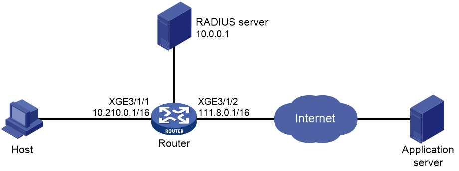
Procedure
1. Assign IP addresses to interfaces as show in Figure 45. (Details not shown.)
2. On the RADIUS server, set the shared key for secure communication to expert and add a user account and password for the PPP user connected to the router. (Details not shown.)
3. Configure the router:
¡ Create RADIUS scheme.
# Create RADIUS scheme rad.
<Router> system-view
[Router] radius scheme rad
# Specify the IP address of the primary accounting server and the primary authentication server as 10.0.0.1, and the service port of the primary accounting server and the primary authentication server as 1813.
[Router-radius-rad] primary accounting 10.0.0.1 1813
[Router-radius-rad] primary authentication 10.0.0.1 1813
# Set the shared key to plaintext expert for secure communication.
[Router-radius-rad] key authentication simple expert
# Include domain names in the usernames sent to the RADIUS server.
[Router-radius-rad] user-name-format with-domain
[Router-radius-rad] quit
¡ Configure an ISP domain.
# Create ISP domain cgn.
[Router] domain name cgn
# Specify RADIUS scheme rad for PPP user authentication, authorization, and accounting.
[Router-isp-cgn] authentication ppp radius-scheme rad
[Router-isp-cgn] authorization ppp radius-scheme rad
[Router-isp-cgn] accounting ppp radius-scheme rad
# Specify the user address type as private IPv4 address. Success authentication of such users can trigger NAT.
[Router-isp-cgn] user-address-type private-ipv4
# Specify IP pool 1 for users in ISP domain cgn.
[Router-isp-cgn] authorization-attribute ip-pool 1
[Router-isp-cgn] quit
¡ Bind the load-sharing user group to the NAT instance.
# Create a user group named ugrp.
[Router] user-group ugrp
[Router-ugroup-ugrp] quit
# Bind user group ugrp to NAT instance inst.
[Router] domain name cgn
[Router-isp-cgn] user-group name ugrp bind nat-instance inst
[Router-isp-cgn] quit
¡ Enable DHCP.
[Router] dhcp enable
¡ Configure PPPoE authentication.
# Configure IP pool 1.
[Router] ip pool 1 bas local
[Router-ip-pool-pool1] gateway 10.210.0.1 24
[Router-ip-pool-pool1] forbidden-ip 10.210.0.1
[Router-ip-pool-pool1] quit
# Configure interface Virtual-Template 1 to use CHAP for authentication.
[Router] interface virtual-template 1
[Router-Virtual-Template1] ppp authentication-mode chap domain cgn
[Router-Virtual-Template1] ip address 10.210.0.1 24
[Router-Virtual-Template1] quit
# Enable PPPoE server on Ten-GigabitEthernet 3/1/1 and bind the interface to Virtual-Template 1.
[Router] interface ten-gigabitethernet 3/1/1
[Router-Ten-GigabitEthernet3/1/1] pppoe-server bind virtual-template 1
[Router-Ten-GigabitEthernet3/1/1] quit
¡ Configure a failover group.
# Create failover group failgrp.
[Router] failover group failgrp id 1
# Specify the primary node and the secondary node for the failover group.
[Router-failover-group-failgrp] bind slot 2 primary
[Router-failover-group-failgrp] bind slot 3 secondary
[Router-failover-group-failgrp] quit
¡ Configure a service instance group.
# Create service instance group sgrp.
[Router] service-instance-group sgrp
# Associate the service instance group with failover group failgrp.
[Router-service-instance-group-sgrp] failover-group failgrp
[Router-service-instance-group-sgrp] quit
¡ Configure an advanced ACL.
# Create IPv4 advanced ACL 3000.
[Router] acl advanced 3000
# Configure rules for ACL 3000.
[Router-acl-ipv4-adv-3000] rule permit ip user-group ugrp
[Router-acl-ipv4-adv-3000] quit
¡ Configure a QoS policy to redirect IP packets matching user group ugrp to the NAT instance.
# Configure traffic class c1 to identify IP packets of users in user group ugrp.
[Router] traffic classifier c1
[Router-classifier-c1] if-match acl 3000
[Router-classifier-c1] quit
# Configure traffic class b1 to bind the matching traffic to NAT instance inst.
[Router] traffic behavior b1
[Router-behavior-b1] bind nat-instance inst
[Router-behavior-b1] quit
# Create QoS policy cb1 and associate the traffic class with the traffic behavior.
[Router] qos policy cb1
[Router-qospolicy-cb1] classifier c1 behavior b1
[Router-qospolicy-cb1] quit
# Apply QoS policy to the inbound traffic on Ten-GigabitEthernet 3/1/1.
[Router] interface ten-gigabitethernet 3/1/1
[Router-Ten-GigabitEthernet3/1/1] qos apply policy cb1 inbound
[Router-Ten-GigabitEthernet3/1/1] quit
¡ Configure global NAT.
# Create address group 1. Add public address 111.8.0.200, specify the port range as 1024 to 65535, and set the port block size to 10.
[Router] nat address-group 1
[Router-address-group-1] port-block block-size 10
[Router-address-group-1] port-range 1024 65535
[Router-address-group-1] address 111.8.0.200 111.8.0.200
[Router-address-group-1] quit
# Create NAT instance inst.
[Router] nat instance inst id 1
# Associate service instance group sgrp with the NAT instance.
[Router-nat-instance-inst] service-instance-group sgrp
# Configure outbound dynamic NAT to use address group 1 to translate packets permitted by ACL 3000.
[Router-nat-instance-inst] nat outbound 3000 address-group 1
[Router-nat-instance-inst] quit
Verifying the configuration
# Initiate a connection from the PPPoE client by entering the username and password.
# Execute the display access-user auth-type ppp verbose command to display detailed information about the PPP access user, including the private IP address, translated public IP address, and port block. (Details not shown.)
# Verify that a dynamic port block-based entry has been created for the user.
[Router] display nat port-block dynamic slot 2
Slot 2:
Local VPN Local IP Global IP Port block Connections Extend
--- 10.210.0.4 111.8.0.200 1314-1323 1 ---
Total mappings found: 1
Example: Configuring NAT Server for external-to-internal access
Network configuration
As shown in Figure 46, a company uses private IP addresses on network 10.110.10.1/16 and public IP address 202.38.1.1. Configure the NAT Server feature to allow the external user to access the internal FTP server by using IP address 202.38.1.1 and port number 21.

Procedure
1. Configure the device:
¡ Specify IP addresses for the interfaces on the device.
<DeviceA> system-view
[DeviceA] interface ten-gigabitethernet 3/1/1
[DeviceA-Ten-GigabitEthernet3/1/1] ip address 10.110.10.10 255.255.0.0
[DeviceA-Ten-GigabitEthernet3/1/1] quit
[DeviceA] interface ten-gigabitethernet 3/1/2
[DeviceA-Ten-GigabitEthernet3/1/2] ip address 202.38.1.10 255.255.255.0
[DeviceA-Ten-GigabitEthernet3/1/2] quit
¡ Configure failover group cgn1:
# Specify the CGN card in slot 2 as the primary node in failover group cgn1.
[Device] failover group cgn1 id 1
[Device-failover-group-cgn] bind slot 2 primary
[Device-failover-group-cgn] quit
¡ Configure ACL 3000:
# Configure ACL 3000 to identify packets from IP address 10.110.10.1.
[Device] acl advanced 3000
[Device-acl-ipv4-adv-3000] rule 5 permit ip source 10.110.10.1 0
[Device-acl-ipv4-adv-3000] quit
¡ Configure a QoS policy to redirect IP packets to the NAT instance:
# Configure traffic class cgn to identify IP packets.
[Device] traffic classifier cgn
[Device-classifier-cgn] if-match acl 3000
[Device-classifier-cgn] quit
# Configure traffic behavior cgn to bind the matching traffic to NAT instance a.
[Device] traffic behavior cgn
[Device-behavior-cgn] bind nat-instance a
[Device-behavior-cgn] quit
# Create QoS policy cgn and associate the traffic class with the traffic behavior.
[Device] qos policy cgn
[Device-qospolicy-cgn] classifier cgn behavior cgn
[Device-qospolicy-cgn] quit
# Apply QoS policy to the inbound traffic on Ten-GigabitEthernet 3/1/1.
[Device] interface ten-gigabitethernet 3/1/1
[Device-Ten-GigabitEthernet3/1/1] qos apply policy cgn inbound
[Device-Ten-GigabitEthernet3/1/1] quit
¡ Configure service instance group 1:
# Create service instance group 1 and associate it with failover group cgn1.
[Device] service-instance-group 1
[Device-service-instance-group 1] failover-group cgn1
[Device-service-instance-group 1] quit
¡ Configure global NAT:
# Create a NAT instance named a with ID 1.
[Device] nat instance a id 1
# Associate NAT instance a with service instance group 1.
[Device-nat-instance-1] service-instance-group 1
# Configure NAT server to allow external hosts to access the internal FTP server by using address 202.38.1.1 and port number 21.
[Device-nat-instance-1] nat server protocol tcp global 202.38.1.1 21 inside 10.110.10.1 ftp
[Device-nat-instance-1] quit
2. Configure the host:
Configure 202.38.1.10 as the default gateway address for the host.
Verifying the configuration
# Verify that the host on the external network can access the internal server by using the public address. (Details not shown.)
# Display detailed information about NAT sessions.
[Device] display nat session verbose
Initiator:
Source IP/port: 202.38.1.20/53323
Destination IP/port: 202.38.1.1/21
DS-Lite tunnel peer: -
VPN instance/VLAN ID/Inline ID: -/-/-
Protocol: TCP(6)
Inbound interface: Ten-GigabitEthernet3/1/2
Responder:
Source IP/port: 10.110.10.1/21
Destination IP/port: 202.38.1.20/53323
DS-Lite tunnel peer: -
VPN instance/VLAN ID/Inline ID: -/-/-
Protocol: TCP(6)
Inbound interface: Ten-GigabitEthernet3/1/1
State: TCP_ESTABLISHED
Application: FTP
Role: Master
Failover group ID: 1
Start time: 2022-05-19 14:02:28
Initiator->Responder: 0 packets 0 bytes
Responder->Initiator: 0 packets 0 bytes
Total sessions found: 1
Example: Configuring dynamic port block mapping in a NAT instance-based load balancing scenario
Network configuration
As shown in Figure 47, a company has a private subnet 192.168.0.0/16 and use a static global address pool containing subnet 202.38.1.2/24 for address translation. Configure a NAT instance, associate a service instance group with two failover groups, and associate the NAT instance with the service instance group to load balance NAT services.

Procedure
# Assign IP addresses to interfaces as show in Figure 47. (Details not shown.)
# Specify primary nodes in failover groups.
<Device> system-view
[Device] failover group cgn1 id 1
[Device-failover-group-cgn] bind slot 2 primary
[Device-failover-group-cgn] quit
[Device] failover group cgn2 id 2
[Device-failover-group-cgn] bind slot 3 primary
[Device-failover-group-cgn] quit
# Create global address pool 1, add address section 202.38.1.2/24, and set the initial subnet mask length to 27, and the extended subnet mask length to 30.
[Device] nat ip-pool 1
[Device-nat-ip-pool-1] section 0 202.38.1.2 mask 24
[Device-nat-ip-pool-1] subnet length initial 27 extend 30
[Device-nat-ip-pool-1] quit
# Create address group 0, set the port range to 1024 to 65535, the port block size to 300, and the extended port block number to 1.
[Device] nat address-group 0
[Device-address-group-0] port-range 1024 65535
[Device-address-group-0] port-block block-size 300 extended-block-number 1
[Device-address-group-0] quit
# Configure ACL 2000 to identify packets from subnet 192.168.1.0/24.
[Device] acl basic 2000
[Device-acl-ipv4-basic-2000] rule permit source 192.168.1.0 0.0.0.255
[Device-acl-ipv4-basic-2000] quit
# Configure traffic class cgn and traffic behavior cgn to redirect packets matching ACL 2000 to NAT instance a.
[Device] traffic classifier cgn
[Device-classifier-cgn] if-match acl 2000
[Device-classifier-cgn] quit
[Device] traffic behavior cgn
[Device-behavior-cgn] bind nat instance a
[Device-behavior-cgn] quit
# Configure a QoS policy and associate the traffic class with the traffic behavior.
[Device] qos policy cgn
[Device-qospolicy-cgn] classifier cgn behavior cgn
[Device-qospolicy-cgn] quit
# Apply the QoS policy to the inbound traffic on Ten-GigabitEthernet 3/1/1.
[Device] interface ten-gigabitethernet 3/1/1
[Device-Ten-GigabitEthernet3/1/1] qos apply policy cgn inbound
[Device-Ten-GigabitEthernet3/1/1] quit
# Create service instance group 1 and associate it with failover groups cgn1 and cgn2.
[Device] service-instance-group 1
[Device-service-instance-group 1] failover-group cgn1
[Device-service-instance-group 1] failover-group cgn2
[Device-service-instance-group 1] quit
# Configure an outbound NAT rule for NAT instance a. The source IP addresses of the packets permitted by ACL 2000 is translated into the addresses in address group 0.
[Device] nat instance a id 1
[Device-nat-instance-1] nat outbound 2000 address-group 0
# Bind NAT address group 0 to global address pool 1.
[Device-nat-instance-1] nat address-group 0 bind-ip-pool 1
# Associate NAT instance a with service instance group 1.
[Device-nat-instance-1] service-instance-group 1
# Enable flow-triggered port block assignment.
[Device-nat-instance-1] nat port-block flow-trigger enable
[Device-nat-instance-1] quit
Verifying the configuration
# Verify that failover groups cgn1 and cgn2 have obtained addresses.
[Device] display nat instance instance-name a address-group 0
Instance : a
Address group name/ID : 0
IP pool name : 1
Subnet length (Initial/Extended) : 27/30
Usage thresholds (High/Low) : 80%/20%
Total IP usage : 100%
Total port usage : 3%
Address info:
Subnet Mask Total
202.38.1.0 255.255.255.224 32
Failover-group: cgn1
Total IP count : 16
IP usage : 100%
Port usage: 3%
Address info:
StartIP Total Initial
202.38.1.0 16 Y
Failover-group: cgn2
Total IP count : 16
IP usage : 100%
Port usage: 3%
Address info:
StartIP Total Initial
202.38.1.16 16 Y
# Verify that NAT services are load balanced between failover groups cgn1 and cgn2.
[Device] display nat statistics summary
EIM: Total EIM entries.
SPB: Total static port block entries.
DPB: Total dynamic port block entries.
ASPB: Active static port block entries.
ADPB: Active dynamic port block entries.
Chassis Slot Sessions EIM SPB DPB ASPB ADPB
1 0 0 0 0 0 0 0
1 2 127 0 0 3440 0 127
1 3 127 0 0 3440 0 127
1 4 0 0 0 0 0 0
Example: Configuring multi-egress NAT
Network configuration
As shown in Figure 48, users can access the Telnet server to perform remote management and monitoring. Host A and Host B reside on different subnets and access external networks through Device A. Installed with a CGN card, Device A can perform address translation on matching user packets. Configure Device A to meet the following requirements:
· Users on subnet 10.1.2.0/24 access external networks through China Unicom. Device A uses addresses 100.1.1.2 to 100.1.1.20 to translate packets from subnet 10.1.2.0/24.
· Users on subnet 20.1.2.0/24 access external networks through China Telecom. Device A uses addresses 200.1.1.2 to 200.1.1.20 to translate packets from subnet 20.1.2.0/24.
· The Telnet server has two private IP addresses 40.1.1.2/24 and 40.1.2.2/24. For the server to provide remote access services through different carriers, the private IP addresses must be translated into different addresses.
· If address 10.1.1.2 or 20.1.1.2 is unreachable, services from the private side to the public side can be switched to the other output interface on Device A.
· External hosts can use IP address 10.1.1.1 or 20.1.1.1 and port number 23 to access the Telnet server.

Procedure
1. Specify IP addresses for the interfaces on Device A.
<DeviceA> system-view
[DeviceA] interface ten-gigabitethernet 3/1/1
[DeviceA-Ten-GigabitEthernet3/1/1] ip address 30.1.1.1 255.255.255.0
[DeviceA-Ten-GigabitEthernet3/1/1] quit
[DeviceA] interface ten-gigabitethernet 3/1/2
[DeviceA-Ten-GigabitEthernet3/1/2] ip address 10.1.1.1 255.255.255.0
[DeviceA-Ten-GigabitEthernet3/1/2] quit
[DeviceA] interface ten-gigabitethernet 3/1/3
[DeviceA-Ten-GigabitEthernet3/1/3] ip address 20.1.1.1 255.255.255.0
[DeviceA-Ten-GigabitEthernet3/1/3] quit
2. Specify the card in slot 4 as the primary node in failover group cgn.
[DeviceA] failover group cgn id 1
[DeviceA-failover-group-cgn] bind slot 4 primary
[DeviceA-failover-group-cgn] quit
3. Configure service instance group cgn:
# Create service instance group cgn.
[DeviceA] service-instance-group cgn
# Associate service instance group cgn with failover group cgn.
[DeviceA-service-instance-group-cgn] failover-group cgn
[DeviceA-service-instance-group-cgn] quit
4. Configure global NAT.
¡ Configure ACLs:
# Configure ACL 3001 to identify packets from subnet 20.1.2.0/24.
[DeviceA] acl advanced 3001
[DeviceA-acl-ipv4-adv-3001] rule 5 permit ip source 20.1.2.0 0.0.0.255
[DeviceA-acl-ipv4-adv-3001] quit
# Configure ACL 3002 to identify packets from subnet 10.1.2.0/24.
[DeviceA] acl advanced 3002
[DeviceA-acl-ipv4-adv-3002] rule 5 permit ip source 10.1.2.0 0.0.0.255
[DeviceA-acl-ipv4-adv-3002] quit
# Configure ACL 3334 to identify packets from subnet 40.1.0.0/16.
[DeviceA] acl advanced 3334
[DeviceA-acl-ipv4-adv-3334] rule 5 permit ip source 40.1.0.0 0.0.255.255
[DeviceA-acl-ipv4-adv-3334] quit
¡ Configure NAT address groups:
# Create address group 3 and add addresses 200.1.1.2 to 200.1.1.20 to the group.
[DeviceA] nat address-group 3
[DeviceA-address-group-3] address 200.1.1.2 200.1.1.20
[DeviceA-address-group-3] quit
# Create address group 4 and add addresses 100.1.1.2 to 100.1.1.20 to the group.
[DeviceA] nat address-group 4
[DeviceA-address-group-4] address 100.1.1.2 100.1.1.20
[DeviceA-address-group-4] quit
¡ Configure NAT instance cgn:
# Create NAT instance cgn.
[DeviceA] nat instance cgn id 1
# Associate service instance group cgn with the NAT instance.
[DeviceA-nat-instance-cgn] service-instance-group cgn
¡ Configure outbound dynamic NAT:
# Configure outbound dynamic NAT to use address group 3 to translate packets permitted by ACL 3001.
[DeviceA-nat-instance-cgn] nat outbound 3001 address-group 3
# Configure outbound dynamic NAT to use address group 4 to translate packets permitted by ACL 3002.
[DeviceA-nat-instance-cgn] nat outbound 3002 address-group 4
¡ Configure NAT Server:
# Configure a NAT server mapping to allow external hosts to access the Telnet server by using address 10.1.1.1 and port 23.
[DeviceA-nat-instance-cgn] nat server protocol tcp global 10.1.1.1 23 inside 40.1.2.2 23
# Configure a NAT server mapping to allow external hosts to access the Telnet server by using address 20.1.1.1 and port 23.
[DeviceA-nat-instance-cgn] nat server protocol tcp global 20.1.1.1 23 inside 40.1.1.2 23
[DeviceA-nat-instance-cgn] quit
¡ Configure a QoS policy to redirect traffic to the NAT instance for address translation:
# Configure traffic class cgn and traffic behavior cgn..
[DeviceA] traffic classifier cgn operator or
[DeviceA-classifier-cgn] if-match acl 3001
[DeviceA-classifier-cgn] if-match acl 3002
[DeviceA-classifier-cgn] if-match acl 3334
[DeviceA-classifier-cgn] quit
[DeviceA] traffic behavior cgn
[DeviceA-behavior-cgn] bind nat-instance cgn
[DeviceA-behavior-cgn] quit
# Create QoS policy cgn and associate the traffic class with the traffic behavior to redirect packets matching ACL 3001, ACL 3002, and ACL 3334 to NAT instance cgn.
[DeviceA] qos policy cgn
[DeviceA-qospolicy-cgn] classifier cgn behavior cgn
[DeviceA-qospolicy-cgn] quit
# Apply the QoS policy to the inbound traffic on Ten-GigabitEthernet 3/1/1.
[DeviceA] interface ten-gigabitethernet 3/1/1
[DeviceA-Ten-GigabitEthernet3/1/1] qos apply policy cgn inbound
[DeviceA-Ten-GigabitEthernet3/1/1] quit
5. Configure static routing.
[DeviceA] ip route-static 0.0.0.0 0 10.1.1.2
[DeviceA] ip route-static 0.0.0.0 0 20.1.1.2
6. Configure traffic redirection in the outbound direction based on the public addresses after translation.
¡ Configure ACLs:
# Configure ACL 3003 to identify packets from subnet 100.1.1.0/24.
[DeviceA] acl advanced 3003
[DeviceA-acl-ipv4-adv-3003] rule 5 permit ip source 100.1.1.0 0.0.0.255
[DeviceA-acl-ipv4-adv-3003] quit
# Configure ACL 3004 to identify packets from subnet 200.1.1.0/24.
[DeviceA] acl advanced 3004
[DeviceA-acl-ipv4-adv-3004] rule 5 permit ip source 200.1.1.0 0.0.0.255
[DeviceA-acl-ipv4-adv-3004] quit
¡ Configure QoS policies to redirect outbound traffic:
# Configure traffic class unicom and traffic behavior unicom to redirect packets matching ACL 3003 to 10.1.1.2.
[DeviceA] traffic classifier unicom operator and
[DeviceA-classifier-unicom] if-match acl 3003
[DeviceA-classifier-unicom] quit
[DeviceA] traffic behavior unicom
[DeviceA-behavior-unicom] redirect next-hop 10.1.1.2
# Configure QoS policy unicom and associate traffic class unicom with traffic behavior unicom.
[DeviceA] qos policy unicom
[DeviceA-qospolicy-unicom] classifier unicom behavior unicom
[DeviceA-qospolicy-unicom] quit
# Apply QoS policy unicom to the outbound traffic on Ten-GigabitEthernet 3/1/3.
[DeviceA] interface ten-gigabitethernet 3/1/3
[DeviceA-Ten-GigabitEthernet3/1/3] qos apply policy unicom outbound
[DeviceA-Ten-GigabitEthernet3/1/3] quit
# Configure traffic class telecom and traffic behavior telecom to redirect packets matching ACL 3004 to 20.1.1.2.
[DeviceA] traffic classifier telecom operator and
[DeviceA-classifier-telecom] if-match acl 3004
[DeviceA-classifier-telecom] quit
[DeviceA] traffic behavior telecom
[DeviceA-behavior-telecom] redirect next-hop 20.1.1.2
# Configure QoS policy telecom and associate traffic class telecom with traffic behavior telecom.
[DeviceA] qos policy telecom
[DeviceA-qospolicy-telecom] classifier telecom behavior telecom
[DeviceA-qospolicy-telecom] quit
# Apply QoS policy telecom to the outbound traffic on Ten-GigabitEthernet 3/1/2.
[DeviceA] interface ten-gigabitethernet 3/1/2
[DeviceA-Ten-GigabitEthernet3/1/2] qos apply policy telecom outbound
[DeviceA-Ten-GigabitEthernet3/1/2] quit
7. Configure EAA. If one of the next hops is unreachable, or a next hop becomes reachable again, the interface processing services will be changed.
¡ Configure ACLs:
# Configure ACL 3010 to identify packets from subnets 10.1.2.0/24 and 20.1.2.0/24.
[DeviceA] acl advanced 3010
[DeviceA-acl-ipv4-adv-3010] rule 5 permit ip source 10.1.2.0 0.0.0.255
[DeviceA-acl-ipv4-adv-3010] rule 10 permit ip source 20.1.2.0 0.0.0.255
[DeviceA-acl-ipv4-adv-3010] quit
¡ Configure NQA to test the reachability of address 10.1.1.2.
# Create an ICMP echo operation. Specify 10.1.1.2 as the destination IP address of ICMP echo requests.
[DeviceA] nqa entry admin unicom
[DeviceA-nqa-admin-unicom] type icmp-echo
[DeviceA-nqa-admin-unicom-icmp-echo] destination ip 10.1.1.2
# Configure the ICMP echo operation to perform 10 probes.
[DeviceA-nqa-admin-unicom-icmp-echo] probe count 10
# Configure the ICMP echo operation to repeat every 100 milliseconds.
[DeviceA-nqa-admin-unicom-icmp-echo] frequency 100
# Specify Ten-GigabitEthernet 3/1/2 as the output interface for the probe packets.
[DeviceA-nqa-admin-unicom-icmp-echo] out interface ten-gigabitethernet 3/1/2
# Create reaction entry 1. If the number of consecutive probe failures reaches 5, collaboration is triggered.
[DeviceA-nqa-admin-unicom-icmp-echo] reaction 1 checked-element probe-fail threshold-type consecutive 5 action-type trigger-only
[DeviceA-nqa-admin-unicom-icmp-echo] quit
# Start the ICMP echo operation.
[DeviceA] nqa schedule admin unicom start-time now lifetime forever
¡ Configure NQA to test the reachability of address 20.1.1.2.
# Create an ICMP echo operation. Specify 20.1.1.2 as the destination IP address of ICMP echo requests.
[DeviceA] nqa entry admin telecom
[DeviceA-nqa-admin-telecom] type icmp-echo
[DeviceA-nqa-admin-telecom-icmp-echo] destination ip 20.1.1.2
# Configure the ICMP echo operation to perform 10 probes.
[DeviceA-nqa-admin-telecom-icmp-echo] probe count 10
# Configure the ICMP echo operation to repeat every 100 milliseconds.
[DeviceA-nqa-admin-telecom-icmp-echo] frequency 100
# Specify Ten-GigabitEthernet 3/1/3 as the output interface for the probe packets.
[DeviceA-nqa-admin-telecom-icmp-echo] out interface ten-gigabitethernet 3/1/3
# Create reaction entry 2. If the number of consecutive probe failures reaches 5, collaboration is triggered.
[DeviceA-nqa-admin-telecom-icmp-echo] reaction 2 checked-element probe-fail threshold-type consecutive 5 action-type trigger-only
[DeviceA-nqa-admin-telecom-icmp-echo] quit
# Start the ICMP echo operation.
[DeviceA] nqa schedule admin telecom start-time now lifetime forever
¡ Configure track entries:
# Create track entry 1 and associate it with reaction entry 1.
[DeviceA] track 1 nqa entry admin unicom reaction 1
[DeviceA-track-1] quit
# Create track entry 2 and associate it with reaction entry 2.
[DeviceA] track 2 nqa entry admin telecom reaction 2
[DeviceA-track-2] quit
¡ Configure CLI-defined policies. When address 10.1.1.2 is unreachable, user traffic from subnet 10.1.2.0/24 is translated on Ten-GigabitEthernet 3/1/3. When address 10.1.1.2 is reachable again, user traffic from subnet 10.1.2.0/24 is translated on Ten-GigabitEthernet 3/1/2 again.
# Create CLI-defined policy unicomtotelecom.
[DeviceA] rtm cli-policy unicomtotelecom
# When track entry 1 transits to Negative, perform the following tasks in NAT instance cgn:
- Delete the outbound dynamic NAT configuration that uses ACL 3001 and ACL 3002.
- Configure outbound dynamic NAT that uses ACL 3010, and use address group 3 for NAT.
[DeviceA-rtm-unicomtotelecom] event track 1 state negative
[DeviceA-rtm-unicomtotelecom] action 1 cli system
[DeviceA-rtm-unicomtotelecom] action 2 cli nat instance cgn
[DeviceA-rtm-unicomtotelecom] action 3 cli undo nat outbound 3001
[DeviceA-rtm-unicomtotelecom] action 4 cli undo nat outbound 3002
[DeviceA-rtm-unicomtotelecom] action 5 cli nat outbound 3010 address-group 3
# Specify user roles network-operator and network-admin for executing CLI-defined policy unicomtotelecom.
[DeviceA-rtm-unicomtotelecom] user-role network-operator
[DeviceA-rtm-unicomtotelecom] user-role network-admin
# Enable CLI-defined policy unicomtotelecom.
[DeviceA-rtm-unicomtotelecom] commit
[DeviceA-rtm-unicomtotelecom] quit
# Create CLI-defined policy telecombacktounicom.
[DeviceA] rtm cli-policy telecombacktounicom
# When track entry 1 transits to Positive, perform the following tasks in NAT instance cgn:
- Delete the outbound dynamic NAT configuration that uses ACL 3010.
- Configure outbound dynamic NAT that uses ACL 3001, and use address group 3 for NAT.
- Configure outbound dynamic NAT that uses ACL 3002, and use address group 4 for NAT.
[DeviceA-rtm-telecombacktounicom] event track 1 state positive
[DeviceA-rtm-telecombacktounicom] action 1 cli system
[DeviceA-rtm-telecombacktounicom] action 2 cli nat instance cgn
[DeviceA-rtm-telecombacktounicom] action 3 cli undo nat outbound 3010
[DeviceA-rtm-telecombacktounicom] action 4 cli nat outbound 3001 address-group 3
[DeviceA-rtm-telecombacktounicom] action 5 cli nat outbound 3002 address-group 4
# Specify user roles network-operator and network-admin for executing CLI-defined policy telecombacktounicom.
[DeviceA-rtm-telecombacktounicom] user-role network-operator
[DeviceA-rtm-telecombacktounicom] user-role network-admin
# Enable CLI-defined policy telecombacktounicom.
[DeviceA-rtm-telecombacktounicom] commit
[DeviceA-rtm-telecombacktounicom] quit
¡ Configure CLI-defined policies. When address 20.1.1.2 is unreachable, user traffic from subnet 20.1.2.0/24 is translated on Ten-GigabitEthernet 3/1/2. When address 20.1.1.2 is reachable again, user traffic from subnet 10.1.2.0/24 is translated on Ten-GigabitEthernet 3/1/3 again..
# Create CLI-defined policy telecomtounicom.
[DeviceA] rtm cli-policy telecomtounicom
# When track entry 2 transits to Negative, perform the following tasks in NAT instance cgn:
- Delete the outbound dynamic NAT configuration that uses ACL 3001 and ACL 3002.
- Configure outbound dynamic NAT that uses ACL 3010, and use address group 4 for NAT.
[DeviceA-rtm-telecomtounicom] event track 2 state negative
[DeviceA-rtm-telecomtounicom] action 1 cli system
[DeviceA-rtm-telecomtounicom] action 2 cli nat instance cgn
[DeviceA-rtm-telecomtounicom] action 3 cli undo nat outbound 3001
[DeviceA-rtm-telecomtounicom] action 4 cli undo nat outbound 3002
[DeviceA-rtm-telecomtounicom] action 5 cli nat outbound 3010 address-group 4
# Specify user roles network-operator and network-admin for executing CLI-defined policy telecomtounicom.
[DeviceA-rtm-telecomtounicom] user-role network-operator
[DeviceA-rtm-telecomtounicom] user-role network-admin
# Enable CLI-defined policy telecomtounicom.
[DeviceA-rtm-telecomtounicom] commit
[DeviceA-rtm-telecomtounicom] quit
# Create CLI-defined policy unicombacktotelecom.
[DeviceA] rtm cli-policy unicombacktotelecom
# When track entry 2 transits to Positive, perform the following tasks in NAT instance cgn:
- Delete the outbound dynamic NAT configuration that uses ACL 3010.
- Configure outbound dynamic NAT that uses ACL 3001, and use address group 3 for NAT.
- Configure outbound dynamic NAT that uses ACL 3002, and use address group 4 for NAT.
[DeviceA-rtm-unicombacktotelecom] event track 2 state positive
[DeviceA-rtm-unicombacktotelecom] action 1 cli system
[DeviceA-rtm-unicombacktotelecom] action 2 cli nat instance cgn
[DeviceA-rtm-unicombacktotelecom] action 3 cli undo nat outbound 3010
[DeviceA-rtm-unicombacktotelecom] action 4 cli nat outbound 3001 address-group 3
[DeviceA-rtm-unicombacktotelecom] action 5 cli nat outbound 3002 address-group 4
# Specify user roles network-operator and network-admin for executing CLI-defined policy unicombacktotelecom.
[DeviceA-rtm-unicombacktotelecom] user-role network-operator
[DeviceA-rtm-unicombacktotelecom] user-role network-admin
# Enable CLI-defined policy unicombacktotelecom.
[DeviceA-rtm-unicombacktotelecom] commit
[DeviceA-rtm-unicombacktotelecom] quit
Verifying the configuration
# Display detailed information about NAT sessions to verify that Host A can access Host X.
[DeviceA] display nat session verbose
Slot 4:
Initiator:
Source IP/port: 10.1.2.1/282
Destination IP/port: 111.11.1.1/2048
DS-Lite tunnel peer: -
VPN instance/VLAN ID/Inline ID: -/-/-
Protocol: ICMP(1)
Inbound interface: Ten-GigabitEthernet3/1/1
Responder:
Source IP/port: 111.11.1.1/4
Destination IP/port: 100.1.1.7/0
DS-Lite tunnel peer: -
VPN instance/VLAN ID/Inline ID: -/-/-
Protocol: ICMP(1)
Inbound interface: Ten-GigabitEthernet3/1/2
State: ICMP_REPLY
Application: OTHER
Role: Master
Failover group ID: 1
Start time: 2022-05-30 21:07:09 TTL: 18s
Initiator->Responder: 0 packets 0 bytes
Responder->Initiator: 0 packets 0 bytes
Total sessions found: 1
# Display detailed information about NAT sessions to verify that Host B can access Host X.
[DeviceA] display nat session verbose
Slot 4:
Initiator:
Source IP/port: 20.1.2.1/285
Destination IP/port: 111.11.1.1/2048
DS-Lite tunnel peer: -
VPN instance/VLAN ID/Inline ID: -/-/-
Protocol: ICMP(1)
Inbound interface: Ten-GigabitEthernet3/1/1
Responder:
Source IP/port: 111.11.1.1/1
Destination IP/port: 200.1.1.8/0
DS-Lite tunnel peer: -
VPN instance/VLAN ID/Inline ID: -/-/-
Protocol: ICMP(1)
Inbound interface: Ten-GigabitEthernet3/1/3
State: ICMP_REPLY
Application: OTHER
Role: Master
Failover group ID: 1
Start time: 2022-05-30 21:09:31 TTL: 27s
Initiator->Responder: 0 packets 0 bytes
Responder->Initiator: 0 packets 0 bytes
Total sessions found: 1
# When address 10.1.1.2 is unreachable, verify that the IP address of Host A after translation belongs to address group 3 and Host A receives a reply through interface Ten-GigabitEthernet 3/1/3.
[DeviceA] display nat session verbose
Slot 0:
Initiator:
Source IP/port: 10.1.2.1/289
Destination IP/port: 111.11.1.1/2048
DS-Lite tunnel peer: -
VPN instance/VLAN ID/Inline ID: -/-/-
Protocol: ICMP(1)
Inbound interface: Ten-GigabitEthernet3/1/1
Responder:
Source IP/port: 111.11.1.1/1
Destination IP/port: 200.1.1.7/0
DS-Lite tunnel peer: -
VPN instance/VLAN ID/Inline ID: -/-/-
Protocol: ICMP(1)
Inbound interface: Ten-GigabitEthernet3/1/3
State: ICMP_REPLY
Application: OTHER
Role: Master
Failover group ID: 1
Start time: 2022-05-30 21:15:46 TTL: 19s
Initiator->Responder: 0 packets 0 bytes
Responder->Initiator: 0 packets 0 bytes
Total sessions found: 1
# When address 10.1.1.2 becomes reachable again, verify that the IP address of Host A after translation belongs to address group 4 and Host A receives a reply through interface Ten-GigabitEthernet 3/1/2.
[DeviceA] display nat session verbose
Slot 0:
Initiator:
Source IP/port: 10.1.2.1/292
Destination IP/port: 111.11.1.1/2048
DS-Lite tunnel peer: -
VPN instance/VLAN ID/Inline ID: -/-/-
Protocol: ICMP(1)
Inbound interface: Ten-GigabitEthernet3/1/1
Responder:
Source IP/port: 111.11.1.1/5
Destination IP/port: 100.1.1.7/0
DS-Lite tunnel peer: -
VPN instance/VLAN ID/Inline ID: -/-/-
Protocol: ICMP(1)
Inbound interface: Ten-GigabitEthernet3/1/2
State: ICMP_REPLY
Application: OTHER
Role: Master
Failover group ID: 1
Start time: 2022-05-30 21:17:39 TTL: 22s
Initiator->Responder: 0 packets 0 bytes
Responder->Initiator: 0 packets 0 bytes
Total sessions found: 1
# When address 20.1.1.2 is unreachable, verify that the IP address of Host B after translation belongs to address group 4 and Host B receives a reply through interface Ten-GigabitEthernet 3/1/2.
[DeviceA] display nat session verbose
Slot 0:
Initiator:
Source IP/port: 20.1.2.1/295
Destination IP/port: 111.11.1.1/2048
DS-Lite tunnel peer: -
VPN instance/VLAN ID/Inline ID: -/-/-
Protocol: ICMP(1)
Inbound interface: Ten-GigabitEthernet3/1/1
Responder:
Source IP/port: 111.11.1.1/1
Destination IP/port: 100.1.1.8/0
DS-Lite tunnel peer: -
VPN instance/VLAN ID/Inline ID: -/-/-
Protocol: ICMP(1)
Inbound interface: Ten-GigabitEthernet3/1/2
State: ICMP_REPLY
Application: OTHER
Role: Master
Failover group ID: 1
Start time: 2022-05-30 21:19:38 TTL: 16s
Initiator->Responder: 0 packets 0 bytes
Responder->Initiator: 0 packets 0 bytes
Total sessions found: 1
# When address 20.1.1.2 becomes reachable again, verify that the IP address of Host B after translation belongs to address group 3 and Host B receives a reply through interface Ten-GigabitEthernet 3/1/3.
[DeviceA] display nat session verbose
Slot 0:
Initiator:
Source IP/port: 20.1.2.1/303
Destination IP/port: 111.11.1.1/2048
DS-Lite tunnel peer: -
VPN instance/VLAN ID/Inline ID: -/-/-
Protocol: ICMP(1)
Inbound interface: Ten-GigabitEthernet3/1/1
Responder:
Source IP/port: 111.11.1.1/1
Destination IP/port: 200.1.1.7/0
DS-Lite tunnel peer: -
VPN instance/VLAN ID/Inline ID: -/-/-
Protocol: ICMP(1)
Inbound interface: Ten-GigabitEthernet3/1/3
State: ICMP_REPLY
Application: OTHER
Role: Master
Failover group ID: 1
Start time: 2022-05-30 21:24:15 TTL: 22s
Initiator->Responder: 0 packets 0 bytes
Responder->Initiator: 0 packets 0 bytes
Total sessions found: 1
# Verify that Host X can access the Telnet server by using address 10.1.1.1 and port 23.
[DeviceA] display nat session verbose
Slot 0:
Initiator:
Source IP/port: 111.11.1.1/47115
Destination IP/port: 10.1.1.1/23
DS-Lite tunnel peer: -
VPN instance/VLAN ID/Inline ID: -/-/-
Protocol: TCP(6)
Inbound interface: Ten-GigabitEthernet3/1/2
Responder:
Source IP/port: 40.1.2.2/23
Destination IP/port: 111.11.1.1/47115
DS-Lite tunnel peer: -
VPN instance/VLAN ID/Inline ID: -/-/-
Protocol: TCP(6)
Inbound interface: Ten-GigabitEthernet3/1/1
State: TCP_ESTABLISHED
Application: OTHER
Role: Master
Failover group ID: 1
Start time: 2022-05-30 21:37:56 TTL: 3592s
Initiator->Responder: 0 packets 0 bytes
Responder->Initiator: 0 packets 0 bytes
Total sessions found: 1
# Verify that Host X can access the Telnet server by using address 20.1.1.1 and port 23.
[DeviceA] display nat session verbose
Slot 0:
Initiator:
Source IP/port: 111.11.1.1/47116
Destination IP/port: 20.1.1.1/23
DS-Lite tunnel peer: -
VPN instance/VLAN ID/Inline ID: -/-/-
Protocol: TCP(6)
Inbound interface: Ten-GigabitEthernet3/1/3
Responder:
Source IP/port: 40.1.1.2/23
Destination IP/port: 111.11.1.1/47116
DS-Lite tunnel peer: -
VPN instance/VLAN ID/Inline ID: -/-/-
Protocol: TCP(6)
Inbound interface: Ten-GigabitEthernet3/1/1
State: TCP_ESTABLISHED
Application: OTHER
Role: Master
Failover group ID: 1
Start time: 2022-05-30 21:40:56 TTL: 3591s
Initiator->Responder: 0 packets 0 bytes
Responder->Initiator: 0 packets 0 bytes
Total sessions found: 1
Example: Configuring NAT instance-based NAT Server and outbound NAT
Network configuration
As shown in Figure 49, Host A accesses the Internet after NAT on Device A. A CGN card is installed on slot 4 of Device A, which provides address translation. The company uses private IP addresses on network 192.168.1.0/24 and public IP address 202.38.1.1 to provide FTP services. Configure NAT server and outbound NAT to meet the following requirements:
· Host B can use public IP address 202.38.1.1 and port 21 to access the internal FTP server.
· Users on subnet 192.168.1.0/24 can use public IP addresses 202.38.1.2 and 202.38.1.3 to access the Internet.

Restrictions and guidelines
Make sure the public IPv4 address of the NAT Server is different from the IPv4 addresses in the NAT address group.
Procedure
1. Configure Device A:
¡ Specify IPv4 addresses for the interfaces on Device A.
<DeviceA> system-view
[DeviceA] interface ten-gigabitethernet 3/1/1
[DeviceA-Ten-GigabitEthernet3/1/1] ip address 192.168.1.1 255.255.255.0
[DeviceA-Ten-GigabitEthernet3/1/1] quit
[DeviceA] interface ten-gigabitethernet 3/1/2
[DeviceA-Ten-GigabitEthernet3/1/2] ip address 202.38.1.10 255.255.255.0
[DeviceA-Ten-GigabitEthernet3/1/2] quit
¡ Configure a failover group:
# Specify the CGN card in slot 4 as the primary node in failover group cgn1.
[DeviceA] failover group cgn1 id 1
[DeviceA-failover-group-cgn] bind slot 4 primary
[DeviceA-failover-group-cgn] quit
¡ Configure a service instance group:
# Create service instance group 1 and associate it with failover group cgn1.
[DeviceA] service-instance-group 1
[DeviceA-service-instance-group 1] failover-group cgn1
[DeviceA-service-instance-group 1] quit
¡ Configure ACL:
# Configure ACL 3000 to identify packets from subnet 192.168.1.0/24.
[DeviceA] acl advanced 3000
[DeviceA-acl-ipv4-adv-3000] rule 5 permit ip source 192.168.1.0 0.0.0.255
[DeviceA-acl-ipv4-adv-3000] quit
# Configure ACL 3334 to identify packets from IP address 192.168.1.3.
[DeviceA] acl advanced 3334
[DeviceA-acl-ipv4-adv-3334] rule 5 permit ip source 192.168.1.3 0
[DeviceA-acl-ipv4-adv-3334] quit
¡ Configure a NAT address group:
# Create address group 0 and add addresses 202.38.1.2 and 202.38.1.3 to the group.
[DeviceA] nat address-group 0
[DeviceA-address-group-0] address 202.38.1.2 202.38.1.3
[DeviceA-address-group-0] quit
¡ Configure a NAT instance:
# Create a NAT instance named a with ID 1.
[DeviceA] nat instance a id 1
# Associate NAT instance a with service instance group 1.
[DeviceA-nat-instance-a] service-instance-group 1
# Configure outbound dynamic NAT to use NAT address group 0 to translate packets permitted by ACL 3000.
[DeviceA-nat-instance-a] nat outbound 3000 address-group 0
# Configure a NAT server mapping to allow external users to access the FTP server by using address 202.38.1.1 and port 21.
[DeviceA-nat-instance-a] nat server protocol tcp global 202.38.1.1 21 inside 192.168.1.3 ftp
[DeviceA-nat-instance-a] quit
¡ Configure a QoS policy to redirect traffic to the NAT instance for address translation:
# Configure traffic class cgn and traffic behavior cgn.
[DeviceA] traffic classifier cgn operator or
[DeviceA-classifier-cgn] if-match acl 3000
[DeviceA-classifier-cgn] if-match acl 3334
[DeviceA-classifier-cgn] quit
[DeviceA] traffic behavior cgn
[DeviceA-behavior-cgn] bind nat-instance a
[DeviceA-behavior-cgn] quit
# Create QoS policy cgn and associate the traffic class with the traffic behavior.
[DeviceA] qos policy cgn
[DeviceA-qospolicy-cgn] classifier cgn behavior cgn
[DeviceA-qospolicy-cgn] quit
# Apply the QoS policy to the inbound traffic on Ten-GigabitEthernet 3/1/1.
[DeviceA] interface ten-gigabitethernet 3/1/1
[DeviceA-Ten-GigabitEthernet3/1/1] qos apply policy cgn inbound
[DeviceA-Ten-GigabitEthernet3/1/1] quit
2. Configure Host B:
Make sure Host B and Device A can reach each other.
Verifying the configuration
# Enter the IP address of the WWW server in the address bar of the Web browser on Host A. Display NAT session information generated on Device A when Host A accesses the WWW server.
[DeviceA] display nat session verbose
Slot 4:
Initiator:
Source IP/port: 192.168.1.2/9664
Destination IP/port: 200.168.1.2/80
DS-Lite tunnel peer: -
VPN instance/VLAN ID/Inline ID: -/-/-
Protocol: TCP(6)
Inbound interface: Ten-GigabitEthernet3/1/1
Responder:
Source IP/port: 200.168.1.2/80
Destination IP/port: 202.38.1.3/1024
DS-Lite tunnel peer: -
VPN instance/VLAN ID/Inline ID: -/-/-
Protocol: TCP(6)
Inbound interface: Ten-GigabitEthernet3/1/2
State: TCP_ESTABLISHED
Application: HTTP
Role: Master
Failover group ID: 1
Start time: 2022-11-24 15:50:17 TTL: 3592s
Initiator->Responder: 0 packets 0 bytes
Responder->Initiator: 0 packets 0 bytes
Total sessions found: 1
# Host B can use public IP address 202.38.1.1 and port 21 to access the internal FTP server. Display NAT session information generated on Device A when Host B accesses the FTP server.
[DeviceA] display nat session verbose
Slot 4:
Initiator:
Source IP/port: 200.168.1.1/11904
Destination IP/port: 202.38.1.1/21
DS-Lite tunnel peer: -
VPN instance/VLAN ID/Inline ID: -/-/-
Protocol: TCP(6)
Inbound interface: Ten-GigabitEthernet3/1/2
Responder:
Source IP/port: 192.168.1.3/21
Destination IP/port: 200.168.1.1/11904
DS-Lite tunnel peer: -
VPN instance/VLAN ID/Inline ID: -/-/-
Protocol: TCP(6)
Inbound interface: Ten-GigabitEthernet3/1/1
State: TCP_ESTABLISHED
Application: FTP
Role: Master
Failover group ID: 1
Start time: 2022-11-24 15:50:17 TTL: 3596s
Initiator->Responder: 0 packets 0 bytes
Responder->Initiator: 0 packets 0 bytes
Total sessions found: 2
Example: Configuring UP backup on a CUPS network
Network configuration
On a CUPS network as shown in Figure 50, hosts act as PPPoE clients and run the PPPoE client dialup software. Configure devices as follows to allow hosts to access the external server:
· Configure the vBRAS device as the CP device operating in control mode. The vBRAS device is responsible for the NAT module to request public IP subnets from the DHCP module, releases subnets back to it, and renews IP leases.
· Assign Router A and Router B to the same UP failover group. Master/backup switchover for the failover group is determined by the vBRAS device. Both the routers work in user mode:
¡ Configure Router A as the master UP device. Router A assigns IP addresses to access users when triggered by the collaboration between access users and NAT, and translates private IP addresses into public IP addresses together with port translation. Router A also forwards data packets based on the user session information.
¡ Configure Router B as the backup UP device. Router B receives service backup information, including information about addresses that CP device assigns to the master UP device and user session information on the master UP device.
· CGN cards installed on Router A and Router B act as nodes in the failover group. The VRRP group created on the backup channel interface determines the node status based on the device role.
· Bind NAT instances on Router A and Router B to VSRP groups. Only the master device in the VSRP group performs address translation for traffic that matches the rules in the NAT instance.
· Make sure user access services and NAT services are processed on the same device.
· Use port block-based NAT and public addresses on subnet 202.38.1.0/24. The port range for public addresses is 1024 to 65535, and the port block size is 300.

Table 5 Interface and IP address assignment
|
Device |
Interface |
IP address |
Device |
Interface |
IP address |
|
Router A |
XGE3/1/2 |
4.4.4.1/24 |
Router B |
XGE3/1/2 |
6.6.6.1/24 |
|
Router A |
XGE3/1/3 |
3.1.1.1/24 |
Router B |
XGE3/1/3 |
3.1.1.2/24 |
|
|
Loop1 |
33.3.3.1/24 |
|
Loop1 |
34.3.3.1/32 |
|
|
Loop2 |
100.1.1.1/32 |
|
Loop2 |
101.1.1.1/32 |
|
Core router |
XGE3/1/1 |
4.4.4.2/24 |
vBRAS |
XGE1/1/0 |
192.168.181.2/24 |
|
Core router |
XGE3/1/2 |
6.6.6.2/24 |
|
Loop1 |
8.1.1.1/32 |
|
Core router |
XGE3/1/3 |
192.168.181.1/24 |
|
|
|
Prerequisites
Assign IP addresses to interfaces.
Establish management channels, control channels, and protocol channels between the CP devices and two UP devices. Each UP device uses the IP address of its interface LoopBack 2 to establish a CUSP connection with IP address 8.1.1.1 on the CP device. For more information, see CP and UP connection management configuration in CP and UP Separation Configuration Guide.
Procedure
1. Configure the vBRAS device:
¡ Configure a NAT instance:
# Create a NAT instance named inst with ID 10. The NAT instance ID is the same as the ID of the NAT instance on UP devices.
[vBRAS] nat instance inst id 10
[vBRAS-nat-instance-inst] quit
¡ Configure an IP pool for user address assignment:
# Create an IP pool that assigns IP addresses to BRAS access users, and specify the gateway address 3.3.3.1, network subnet mask 255.255.0.0, and address range 3.3.3.1 to 3.3.255.255.
[vBRAS] ip pool userpool bas local
[vBRAS-ip-pool-userpool] gateway 3.3.3.1 mask 255.255.0.0
[vBRAS-ip-pool-userpool] address range 3.3.3.1 3.3.255.255
# Exclude IP address 3.3.3.1 from dynamic allocation in the IP pool.
[vBRAS-ip-pool-userpool] forbidden-ip 3.3.3.1
[vBRAS-ip-pool-userpool] quit
¡ Configure an ISP domain.
# Create an ISP domain named cgn.
[vBRAS] domain name cgn
# Specify RADIUS scheme rad for PPP user authentication, authorization, and accounting.
[vBRAS-isp-cgn] authentication ppp radius-scheme rad
[vBRAS-isp-cgn] authorization ppp radius-scheme rad
[vBRAS-isp-cgn] accounting ppp radius-scheme rad
[vBRAS-isp-cgn] authorization-attribute ip-pool userpool
# Specify the user address type as private IPv4 address.
[vBRAS-isp-cgn] user-address-type private-ipv4
[vBRAS-isp-cgn] quit
¡ Bind a user group to the NAT instance:
# Create a user group named user.
[vBRAS] user-group user
[vBRAS-ugroup-user] quit
# Bind user group user to NAT instance inst.
[vBRAS] domain name cgn
[vBRAS-isp-cgn] user-group name user bind nat-instance inst
[vBRAS-isp-cgn] quit
¡ Configure a remote interface:
# Create UP 1024 and enter UP-manage view..
[vBRAS] up-manage id 1024
# Create remote interface Remote-XGE1024/3/1/1.
[vBRAS-up-manage-1024] remote interface ten-gigabitethernet 3/1/1
[vBRAS-up-manage-1024] quit
# Create UP 1025 and enter UP-manage view..
[vBRAS] up-manage id 1025
# Create remote interface Remote-XGE1025/3/1/1.
[vBRAS-up-manage-1025] remote interface ten-gigabitethernet 3/1/1
[vBRAS-up-manage-1025] quit
¡ Configure DHCP:
# Configure an IP pool and specify 202.38.1.0/24 for dynamic allocation. This example uses nat-central IP pool pool.
[vBRAS] ip pool pool nat-central
[vBRAS-ip-pool-pool] network 202.38.1.0 mask 255.255.255.0
# Specify the mask length for dynamically allocated subnets.
[vBRAS-ip-pool-pool] subnet mask-length 28
[vBRAS-ip-pool-pool] quit
¡ Configure the PPPoE server:
# Create a PPPoE user.
[vBRAS] local-user cp class network
[vBRAS-luser-network-user1] password simple 123456TESTplat&!
[vBRAS-luser-network-user1] service-type ppp
[vBRAS-luser-network-user1] quit
# Configure Virtual-Template 1 to use PAP for authentication.
[vBRAS] interface virtual-template1
[vBRAS-Virtual-Template1] ppp authentication-mode pap domain cgn
[vBRAS-Virtual-Template1] quit
# Enable the PPPoE server on Remote-XGE1024/3/1/1, and bind the interface to Virtual-Template 1.
[vBRAS] interface remote-xge 1024/3/1/1
[vBRAS-Remote-XGE1024/3/1/1] pppoe-server bind virtual-template 1
[vBRAS-Remote-XGE1024/3/1/1] quit
# Enable the PPPoE server on Remote-XGE1025/3/1/1 and bind the interface to Virtual-Template 1.
[vBRAS] interface remote-xge 1025/3/1/1
[vBRAS-Remote-XGE1025/3/1/1] pppoe-server bind virtual-template 1
[vBRAS-Remote-XGE1025/3/1/1] quit
¡ Configure a UP backup group:
# Create UP backup group 1, and add UP 1024 and UP 1025 to the backup group.
[vBRAS] up-backup-group 1
[vBRAS-up-backup-group-1] backup up-id 1024 local-ip 33.3.3.1
[vBRAS-up-backup-group-1] backup up-id 1025 local-ip 34.3.3.1
[vBRAS-up-backup-group-1] quit
# Configure one failover group for hot backup, and enable IP address advertisement on the master and backup interfaces.
[vBRAS] up-backup-profile 1 hot-standby
[vBRAS-up-backup-profile-1] backup route-advertise master-cost 10 backup-cost 30
# Specify the master and backup interfaces for the UP backup group. To ensure an unchanged MAC address after master/backup switchover, the UP device replies with the virtual MAC address created by virtual router ID 2 when receiving a user access request.
[vBRAS-up-backup-profile-1] backup-group master remote-xge 1024/3/1/1 backup remote-xge 1025/3/1/1 vrid 2 resource-id 1
¡ Configure static routing:
[vBRAS] ip route-static 100.1.1.0 24 192.168.181.1
[vBRAS] ip route-static 101.1.1.0 24 192.168.181.1
[vBRAS] ip route-static 4.4.4.0 24 192.168.181.1
[vBRAS] ip route-static 6.6.6.0 24 192.168.181.1
2. Configure Router A:
¡ Configure a work mode for Router A.
# Configure Router A to operate in user mode.
[RouterA] work-mode user-plane
¡ Configure a failover group:
# Create failover group dp, and assign the CGN card in the specified slot to the failover group. Bind the failover group to VRRP group 1 on Ten-GigabitEthernet 3/1/1.1.
[RouterA] failover group dp
[RouterA-failover-group-dp] bind slot 3 vrrp
[RouterA-failover-group-dp] bind-vrrp 1 interface ten-gigabitethernet 3/1/1.1
# Specify a backup channel with local IP address 3.1.1.1 and remote IP address 3.1.1.2 for inter-system service backup.
[RouterA-failover-group-dp] remote-backup local 3.1.1.1 peer 3.1.1.2 port 10000
[RouterA-failover-group-dp] quit
¡ Create a user group named user.
[RouterA] user-group user
[RouterA-ugroup-user] quit
¡ Configure a NAT address group:
# Create NAT address group 1.
[RouterA] nat address-group 1
# Configure port block parameters and set the port block size to 300.
[RouterA-address-group-1] port-block block-size 300
[RouterA-address-group-1] port-range 1024 65535
[RouterA-address-group-1] quit
¡ Configure a service instance group:
# Create service instance group sgrp.
[RouterA] service-instance-group sgrp
# Associate service instance group sgrp to failover group dp.
[RouterA-service-instance-group-sgrp] failover-group dp
[RouterA-service-instance-group-sgrp] quit
¡ Configure an advanced ACL:
# Create IPv4 advanced ACL 3000.
[RouterA] acl advanced 3000
# Configure a rule to permit only packets of users in user group user.
[RouterA-acl-ipv4-adv-3000] rule permit ip user-group user
[RouterA-acl-ipv4-adv-3000] quit
¡ Configure a QoS policy to redirect IP packets of user group user to the NAT instance:
# Configure traffic class c1 to identify IP packets of users in user group user.
[RouterA] traffic classifier c1
[RouterA-classifier-c1] if-match acl 3000
[RouterA-classifier-c1] quit
# Configure traffic class b1 to bind the matching traffic to NAT instance inst.
[RouterA] traffic behavior b1
[RouterA-behavior-b1] bind nat-instance inst
[RouterA-behavior-b1] quit
# Create QoS policy cb1 and associate the traffic class with the traffic behavior.
[RouterA] qos policy cb1
[RouterA-qospolicy-cb1] classifier c1 behavior b1
[RouterA-qospolicy-cb1] quit
# Apply QoS policy to the inbound traffic on Ten-GigabitEthernet 3/1/1.
[RouterA] interface ten-gigabitethernet 3/1/1
[RouterA-Ten-GigabitEthernet3/1/1] qos apply policy cb1 inbound
[RouterA-Ten-GigabitEthernet3/1/1] quit
¡ Configure a dynamic global address pool:
# Create a dynamic global address pool named pool1.
[RouterA] nat ip-pool pool1 dynamic
# Specify IDs of the local and peer dynamic global address pools.
[RouterA-nat-ip-pool-pool1] up-backup local-up-id 1024 peer-up-id 1025
# Bind global address pool pool1 to DHCP pool pool.
[RouterA-nat-ip-pool-pool1] bind dhcp-server-pool pool
[RouterA-nat-instance-inst] quit
¡ Configure a NAT instance:
# Create a NAT instance named inst with ID 10.
[RouterA] nat instance inst id 10
# Associate NAT instance inst to service instance group sgrp.
[RouterA-nat-instance-inst] service-instance-group sgrp
# Configure outbound dynamic NAT to use NAT address group 1 to translate packets permitted by ACL 3000.
[RouterA-nat-instance-inst] nat outbound 3000 address-group 1
# Bind NAT address group 1 to global address pool pool1.
[RouterA-nat-instance-inst] nat address-group 1 bind-ip-pool pool1
[RouterA-nat-instance-inst] quit
¡ Configure a VRRP group. To enable master/backup fast switchover, set the priority of the device to a higher value in the VRRP group, or set the VRRP advertisement interval to a smaller value on the master device.
# Create VRRP group 1, assign an IP address to Ten-GigabitEthernet 3/1/1.1, set the virtual IP address of the VRRP group, and apply a priority to Router A.
[RouterA] interface ten-gigabitethernet 3/1/1.1
[RouterA-Ten-GigabitEthernet3/1/1.1] ip address 5.1.1.1 255.255.255.0
[RouterA-Ten-GigabitEthernet3/1/1.1] vrrp vrid 1 virtual-ip 5.1.1.100
[RouterA-Ten-GigabitEthernet3/1/1.1] vrrp vrid 1 priority 254
# Set the hold time for the VRRP group in Initialize state to 300 seconds.
[RouterA-Ten-GigabitEthernet3/1/1.1] vrrp vrid 1 initialize state-hold-time 300
# Configure Router A to operate in preemptive mode and set the preemption delay to 30000 centiseconds. Make sure the delay time is the same as the switchback delay time configured for the UP backup group on the vBRAS device.
[RouterA-Ten-GigabitEthernet3/1/1.1] vrrp vrid 1 preempt-mode delay 30000
[RouterA-Ten-GigabitEthernet3/1/1.1] quit
# Create track entry 1 and associate it with failover group dp. If the CGN card on Router A fails, the track entry transits to Negative.
[RouterA] track 1 failover-group dp
# Create track entry 2 and associate it with BFD to test the reachability of Router B.
[RouterA] track 2 bfd echo interface ten-gigabitethernet 3/1/1.1 remote ip 5.1.1.2 local ip 5.1.1.1
# Create track entry 3 and associate it with BFD to monitor the link between remote IP address 4.4.4.2 and local IP address 4.4.4.1 by sending BFD echo packets out of Ten-GigabitEthernet 3/1/2. If the uplink fails, the track entry transits to Negative.
[RouterA] track 3 bfd echo interface ten-gigabitethernet 3/1/2 remote ip 4.4.4.2 local ip 4.4.4.1
# Create track entry 4 and associate it with NQA. If the route between Router A and the vBRAS device is unreachable, the track entry transits to Negative.
[RouterA] nqa entry admin 1
[RouterA-nqa-admin-1] type icmp-echo
[RouterA-nqa-admin-1] destination ip 192.168.181.2
[RouterA-nqa-admin-1] frequency 100
[RouterA-nqa-admin-1] probe timeout 1000
[RouterA-nqa-admin-1] reaction 1 checked-element probe-fail threshold-type consecutive 2 action-type trigger-only
[RouterA-nqa-admin-1] source ip 4.4.4.1
[RouterA-nqa-admin-1] quit
[RouterA] track 4 nqa entry admin 1 reaction 1
[RouterA] nqa schedule admin 1 start-time now lifetime forever
# Create track entry 5 of the Boolean type list to monitor the uplink, the downlink, and the status of CGN cards. If the status of all objects in the list are Positive, the track entry transits to Positive.
[RouterA] track 5 list boolean and
[RouterA-track-5] object 1
[RouterA-track-5] object 3
[RouterA-track-5] object 4
# Configure track entry 5 for user-plane switchover to monitor the uplink, the downlink, and the status of CGN cards. If the status of all objects in the list are Positive, the track entry transits to Positive.
[RouterA] user-plane switch-over track 5
# Configure monitoring on track entry 2 and 5 on Ten-GigabitEthernet 3/1/1.1. If track entry 2 transits to Negative and Router A is a backup device, Router A becomes the master quickly. If track entry 5 transits to Negative, the priority of Router A is reduced to 0.
[RouterA] interface ten-gigabitethernet 3/1/1.1
[RouterA-Ten-GigabitEthernet3/1/1.1] vrrp vrid 1 track 2 switchover
[RouterA-Ten-GigabitEthernet3/1/1.1] vrrp vrid 1 track 5 priority reduced 255
[RouterA-Ten-GigabitEthernet3/1/1.1] quit
On Ten-GigabitEthernet 3/1/1.1, set the minimum interval to 10 milliseconds for receiving BFD echo packets and set the single-hop detection time multiplier to 3.
[RouterA] interface ten-gigabitethernet 3/1/1.1
[RouterA-Ten-GigabitEthernet3/1/1.1] bfd min-echo-receive-interval 10
[RouterA-Ten-GigabitEthernet3/1/1.1] bfd echo enable
[RouterA-Ten-GigabitEthernet3/1/1.1] bfd detect-multiplier 3
[RouterA-Ten-GigabitEthernet3/1/1.1] quit
# Set the interface identity number to 1 on Ten-GigabitEthernet 3/1/1.
[RouterA-Ten-GigabitEthernet3/1/1] identity-number 1
[RouterA-Ten-GigabitEthernet3/1/1] quit
# On Ten-GigabitEthernet 3/1/2, configure BFD attributes. Set the minimum interval to 10 milliseconds for receiving BFD echo packets and set the single-hop detection time multiplier to 3.
[RouterA] interface ten-gigabitethernet 3/1/2
[RouterA-Ten-GigabitEthernet3/1/2] bfd min-echo-receive-interval 10
[RouterA-Ten-GigabitEthernet3/1/2] bfd min-transmit-interval 10
[RouterA-Ten-GigabitEthernet3/1/2] bfd min-receive-interval 10
[RouterA-Ten-GigabitEthernet3/1/2] bfd echo enable
[RouterA-Ten-GigabitEthernet3/1/2] bfd detect-multiplier 3
[RouterA-Ten-GigabitEthernet3/1/2] quit
# Set the interface identity number to 1 on Ten-GigabitEthernet 3/1/2.
[RouterA-Ten-GigabitEthernet3/1/2] identity-number 2
[RouterA-Ten-GigabitEthernet3/1/2] quit
¡ Enable session synchronization.
[RouterA] session synchronization enable
¡ Configure VSRP:
# Create VSRP group 1.
[RouterA] vsrp peer 1
[RouterA-vsrp-peer-1] peer 34.3.3.1 local 33.3.3.1
# Create VSRP instance 1 and set its backup ID to 1.
[RouterA] vsrp instance 1
[RouterA-vsrp-instance-1] backup id 1 peer 1
# Bind VSRP instance 1 to VRRP group 1 on Ten-GigabitEthernet 3/1/1.1.
[RouterA-vsrp-instance-1] bind vrrp vrid 1 interface ten-gigabitethernet 3/1/1.1
# Bind NAT instance inst to VSRP instance 1.
[RouterA] nat instance inst
[RouterA-nat-instance-inst] bind vsrp-instance 1
[RouterA-nat-instance-inst] quit
¡ Configure IS-IS:
# Enable IS-IS process 1 and set the system ID to 0000.0000.0002 and area ID to 00.
[RouterA] isis 1
[RouterA-isis-1] network-entity 00.0000.0000.0002.00
# Configure the router to receive and send only wide cost style packets.
[RouterA-isis-1] cost-style wide
# Configure direct and UNR route redistributions.
[RouterA-isis-1] address-family ipv4 unicast
[RouterA-isis-1-ipv4] import-route direct inherit-cost
[RouterA-isis-1-ipv4] import-route unr inherit-cost
[RouterA-isis-1-ipv4] quit
[RouterA-isis-1] quit
# Enable IS-IS on Ten-GigabitEthernet 3/1/2 and LoopBack 1, and enable BFD on Ten-GigabitEthernet 3/1/2.
[RouterA] interface ten-gigabitethernet 3/1/2
[RouterA-Ten-GigabitEthernet3/1/2] isis enable 1
[RouterA-Ten-GigabitEthernet3/1/2] isis bfd enable
[RouterA-Ten-GigabitEthernet3/1/2] quit
[RouterA] interface loopback 1
[RouterA-LoopBack1] isis enable 1
3. Configure Router B:
¡ Configure a work mode for Router B.
# Configure Router B to operate in user mode.
[RouterB] work-mode user-plane
¡ Configure a failover group:
# Create failover group dp, and assign the CGN card in the specified slot to the failover group. Bind the failover group to VRRP group 1 on Ten-GigabitEthernet 3/1/1.1.
[RouterB] failover group dp
[RouterB-failover-group-dp] bind slot 3 vrrp
[RouterB-failover-group-dp] bind-vrrp 1 interface ten-gigabitethernet 3/1/1.1
# Specify a backup channel with local IP address 3.1.1.2 and remote IP address 3.1.1.1 for inter-system service backup.
[RouterB-failover-group-dp] remote-backup local 3.1.1.2 peer 3.1.1.1 port 10000
[RouterB-failover-group-dp] quit
¡ Create a user group named user.
[RouterB] user-group user
[RouterB-ugroup-user] quit
¡ Configure a NAT address group:
# Create NAT address group 1.
[RouterB] nat address-group 1
# Configure port block parameters and set the port block size to 300.
[RouterB-address-group-1] port-block block-size 300
[RouterB-address-group-1] port-range 1024 65535
[RouterB-address-group-1] quit
¡ Configure a service instance group:
# Create service instance group sgrp.
[RouterB] service-instance-group sgrp
# Associate service instance group sgrp to failover group dp.
[RouterB-service-instance-group-sgrp] failover-group dp
[RouterB-service-instance-group-sgrp] quit
¡ Configure an advanced ACL:
# Create IPv4 advanced ACL 3000.
[RouterB] acl advanced 3000
# Configure a rule to permit only packets of users in user group user.
[RouterB-acl-ipv4-adv-3000] rule permit ip user-group user
[RouterB-acl-ipv4-adv-3000] quit
¡ Configure a QoS policy to redirect IP packets of user group user to the NAT instance:
# Configure traffic class c1 to identify IP packets of users in user group user.
[RouterB] traffic classifier c1
[RouterB-classifier-c1] if-match acl 3000
[RouterB-classifier-c1] quit
# Configure traffic class b1 to bind the matching traffic to NAT instance inst.
[RouterB] traffic behavior b1
[RouterB-behavior-b1] bind nat-instance inst
[RouterB-behavior-b1] quit
# Create QoS policy cb1 and associate the traffic class with the traffic behavior.
[RouterB] qos policy cb1
[RouterB-qospolicy-cb1] classifier c1 behavior b1
[RouterB-qospolicy-cb1] quit
# Apply QoS policy to the inbound traffic on Ten-GigabitEthernet 3/1/1.
[RouterB] interface ten-gigabitethernet 3/1/1
[RouterB-Ten-GigabitEthernet3/1/1] qos apply policy cb1 inbound
[RouterB-Ten-GigabitEthernet3/1/1] quit
¡ Configure a dynamic global address pool:
# Create a dynamic global address pool pool1 and specify it as a backup pool.
[RouterB] nat ip-pool pool1 dynamic backup
# Specify IDs of the local and peer dynamic global address pools.
[RouterB-nat-ip-pool-pool1] up-backup local-up-id 1025 peer-up-id 1024
# Bind global address pool pool1 to DHCP pool pool.
[RouterB-nat-ip-pool-pool1] bind dhcp-server-pool pool
[RouterB-nat-instance-inst] quit
¡ Configure a NAT instance:
# Create a NAT instance named inst with ID 10.
[RouterB] nat instance inst id 10
# Associate NAT instance inst to service instance group sgrp.
[RouterB-nat-instance-inst] service-instance-group sgrp
# Configure outbound dynamic NAT to use NAT address group 1 to translate packets permitted by ACL 3000.
[RouterB-nat-instance-inst] nat outbound 3000 address-group 1
# Bind the NAT address group to global address pool pool1.
[RouterB-nat-instance-inst] nat address-group 1 bind-ip-pool pool1
[RouterB-nat-instance-inst] quit
¡ Configure a VRRP group. To enable master/backup fast switchover, set the priority of the device to a higher value in the VRRP group, or set the VRRP advertisement interval to a smaller value on the master device. For more information about VRRP, see High Availability Configuration Guide.
# Create VRRP group 1, assign an IP address to Ten-GigabitEthernet 3/1/1.1, set the virtual IP address of the VRRP group, and apply a priority to Router B.
[RouterB] interface ten-gigabitethernet 3/1/1.1
[RouterB-Ten-GigabitEthernet3/1/1.1] ip address 5.1.1.2 255.255.255.0
[RouterB-Ten-GigabitEthernet3/1/1.1] vrrp vrid 1 virtual-ip 5.1.1.100
[RouterB-Ten-GigabitEthernet3/1/1.1] vrrp vrid 1 priority 253
# Set the hold time for the VRRP group in Initialize state to 300 seconds.
[RouterB-Ten-GigabitEthernet3/1/1.1] vrrp vrid 1 initialize state-hold-time 300
# Configure Router A to operate in preemptive mode and set the preemption delay to 30000 centiseconds. Make sure the delay time is the same as the switchback delay time configured for the UP backup group on the vBRAS device.
[RouterB-Ten-GigabitEthernet3/1/1.1] vrrp vrid 1 preempt-mode delay 30000
[RouterB-Ten-GigabitEthernet3/1/1.1] quit
# Create track entry 1 and associate it with failover group dp. If the CGN card on Router B fails, the track entry transits to Negative.
[RouterB] track 1 failover-group dp
# Create track entry 2 and associate it with BFD to test the reachability of Router A.
[RouterB] track 2 bfd echo interface ten-gigabitethernet 3/1/1.1 remote ip 5.1.1.1 local ip 5.1.1.2
# Create track entry 3 and associate it with BFD to monitor the link between remote IP address 6.6.6.2 and local IP address 6.6.6.1 by sending BFD echo packets out of Ten-GigabitEthernet 3/1/2. If the uplink fails, the track entry transits to Negative.
[RouterB] track 3 bfd echo interface ten-gigabitethernet 3/1/2 remote ip 6.6.6.2 local ip 6.6.6.1
# Create track entry 4 and associate it with NQA. If the route between Router B and the vBRAS device is unreachable, the track entry transits to Negative.
[RouterB] nqa entry admin 1
[RouterB-nqa-admin-1] type icmp-echo
[RouterB-nqa-admin-1] destination ip 192.168.181.2
[RouterB-nqa-admin-1] frequency 100
[RouterB-nqa-admin-1] probe timeout 1000
[RouterB-nqa-admin-1] reaction 1 checked-element probe-fail threshold-type consecutive 2 action-type trigger-only
[RouterB-nqa-admin-1] source ip 6.6.6.1
[RouterB-nqa-admin-1] quit
[RouterB] track 4 nqa entry admin 1 reaction 1
[RouterB] nqa schedule admin 1 start-time now lifetime forever
# Create track entry 5 of the Boolean type list to monitor the uplink, the downlink, and the status of CGN cards. If the status of all objects in the list are Positive, the track entry transits to Positive.
[RouterB] track 5 list boolean and
[RouterB-track-5] object 1
[RouterB-track-5] object 3
[RouterB-track-5] object 4
# Configure track entry 5 for user-plane switchover to monitor the uplink, the downlink, and the status of CGN cards. If the status of all objects in the list are Positive, the track entry transits to Positive.
[RouterB] user-plane switch-over track 5
# Configure monitoring on track entry 2 and 5 on Ten-GigabitEthernet 3/1/1.1. If track entry 2 transits to Negative and Router B is a backup device, Router B becomes the master quickly. If track entry 5 transits to Negative, the priority of Router B is reduced to 0.
[RouterB] interface ten-gigabitethernet 3/1/1.1
[RouterB-Ten-GigabitEthernet3/1/1.1] vrrp vrid 1 track 2 switchover
[RouterB-Ten-GigabitEthernet3/1/1.1] vrrp vrid 1 track 5 priority reduced 255
[RouterB-Ten-GigabitEthernet3/1/1.1] quit
On Ten-GigabitEthernet 3/1/1.1, set the minimum interval to 10 milliseconds for receiving BFD echo packets and set the single-hop detection time multiplier to 3.
[RouterB] interface ten-gigabitethernet 3/1/1.1
[RouterB-Ten-GigabitEthernet3/1/1.1] bfd min-echo-receive-interval 10
[RouterB-Ten-GigabitEthernet3/1/1.1] bfd echo enable
[RouterB-Ten-GigabitEthernet3/1/1.1] bfd detect-multiplier 3
[RouterB-Ten-GigabitEthernet3/1/1.1] quit
# Set the interface identity number to 1 on Ten-GigabitEthernet 3/1/1.
[RouterB-Ten-GigabitEthernet3/1/1] identity-number 1
[RouterB-Ten-GigabitEthernet3/1/1] quit
# On Ten-GigabitEthernet 3/1/2, configure BFD attributes. Set the minimum interval to 10 milliseconds for receiving BFD echo packets and set the single-hop detection time multiplier to 3.
[RouterB] interface ten-gigabitethernet 3/1/2
[RouterB-Ten-GigabitEthernet3/1/2] bfd min-echo-receive-interval 10
[RouterB-Ten-GigabitEthernet3/1/2] bfd min-transmit-interval 10
[RouterB-Ten-GigabitEthernet3/1/2] bfd min-receive-interval 10
[RouterB-Ten-GigabitEthernet3/1/2] bfd detect-multiplier 3
# Set the interface identity number to 1 on Ten-GigabitEthernet 3/1/2.
[ROUTERB-Ten-GigabitEthernet3/1/2] identity-number 2
[ROUTERB-Ten-GigabitEthernet3/1/2] quit
¡ Enable session synchronization.
[RouterB] session synchronization enable
¡ Configure VSRP:
# Create VSRP group 1.
[RouterB] vsrp peer 1
[RouterB-vsrp-peer-1] peer 33.3.3.1 local 34.3.3.1
# Create VSRP instance 1 and set its backup ID to 1.
[RouterB] vsrp instance 1
[RouterB-vsrp-instance-1] backup id 1 peer 1
# Bind VSRP instance 1 to VRRP group 1 on Ten-GigabitEthernet 3/1/1.1.
[RouterB-vsrp-instance-1] bind vrrp vrid 1 interface ten-gigabitethernet 3/1/1.1
# Bind NAT instance inst to VSRP instance 1.
[RouterB] nat instance inst
[RouterB-nat-instance-inst] bind vsrp-instance 1
[RouterB-nat-instance-inst] quit
¡ Configure IS-IS:
# Enable IS-IS process 1 and set the system ID to 0000.0000.0003 and area ID to 00.
[RouterB] isis 1
[RouterB-isis-1] network-entity 00.0000.0000.0003.00
# Configure the router to receive and send only wide cost style packets.
[RouterB-isis-1] cost-style wide
# Configure IS-IS fast convergence.
[RouterB-isis-1] timer spf 1 10 10
[RouterB-isis-1] timer lsp-generation 1 10 10
# Configure direct and UNR route redistributions.
[RouterB-isis-1] address-family ipv4 unicast
[RouterB-isis-1-ipv4] import-route direct inherit-cost
[RouterB-isis-1-ipv4] import-route unr inherit-cost
[RouterB-isis-1-ipv4] quit
[RouterB-isis-1] quit
# Enable IS-IS on Ten-GigabitEthernet 3/1/2 and Loopback 1, and enable BFD on Ten-GigabitEthernet 3/1/2.
[RouterB] interface ten-gigabitethernet 3/1/2
[RouterB-Ten-GigabitEthernet3/1/2] isis enable 1
[RouterB-Ten-GigabitEthernet3/1/2] isis bfd enable
[RouterB-Ten-GigabitEthernet3/1/2] quit
[RouterB] interface loopback 1
[RouterB-LoopBack1] isis enable 1
[RouterB-LoopBack1] quit
4. Configure the core router:
# Enable IS-IS process 1 and set the system ID to 0000.0000.0004 and area ID to 00.
[CoreRouter] isis 1
[CoreRouter-isis-1] network-entity 00.0000.0000.0004.00
# Configure the router to receive and send only wide cost style packets.
[CoreRouter-isis-1] cost-style wide
# Enable direct route redistribution.
[CoreRouter-isis-1] address-family ipv4 unicast
[CoreRouter-isis-1-ipv4] import-route direct
# Enable FRR for IS-IS process 1 and configure IS-IS FRR to calculate a backup next hop through LFA calculation for all routes.
[CoreRouter-isis-1-ipv4] fast-reroute lfa
[CoreRouter-isis-1-ipv4] quit
[CoreRouter-isis-1] quit
# Enable IS-IS on Ten-GigabitEthernet 3/1/1, Ten-GigabitEthernet 3/1/2, and Ten-GigabitEthernet 3/1/3, and configure BFD.
[CoreRouter] interface ten-gigabitethernet 3/1/1
[CoreRouter-Ten-GigabitEthernet3/1/1] isis enable 1
[CoreRouter-Ten-GigabitEthernet3/1/1] isis bfd enable
[CoreRouter-Ten-GigabitEthernet3/1/1] bfd min-transmit-interval 10
[CoreRouter-Ten-GigabitEthernet3/1/1] bfd min-receive-interval 10
[CoreRouter-Ten-GigabitEthernet3/1/1] bfd detect-multiplier 3
[CoreRouter-Ten-GigabitEthernet3/1/1] quit
[CoreRouter] interface ten-gigabitethernet 3/1/2
[CoreRouter-Ten-GigabitEthernet3/1/2] isis enable 1
[CoreRouter-Ten-GigabitEthernet3/1/2] isis bfd enable
[CoreRouter-Ten-GigabitEthernet3/1/2] bfd min-transmit-interval 10
[CoreRouter-Ten-GigabitEthernet3/1/2] bfd min-receive-interval 10
[CoreRouter-Ten-GigabitEthernet3/1/2] bfd detect-multiplier 3
[CoreRouter-Ten-GigabitEthernet3/1/2] quit
[CoreRouter] interface ten-gigabitethernet 3/1/3
[CoreRouter-Ten-GigabitEthernet3/1/3] isis enable 1
[CoreRouter-Ten-GigabitEthernet3/1/3] quit
Verifying the configuration
# Verify that the user can access the network from the PPPoE dialup software on a host.
# On the vBRAS device, display allocation statistics about subnets that are requested from the DHCP pool.
[vBRAS] display nat dhcp-server-pool-alloc statistics
DHCP server IP pool allocation statistics for NAT:
Totally 1 DHCP server IP pools.
Pool name: pool
Subnet count: 2
UPID Subnet Mask
------------------------------------------
1024 202.38.1.0 255.255.255.240
1024 202.38.1.16 255.255.255.240
# On Router A, display information about the dynamic global address pool pool1 to verify that the pool has obtained IP addresses from the CP device.
[RouterA] display nat ip-pool
NAT IP pool information:
Totally 1 NAT ip pools.
Pool name : pool1
Type of pool : Dynamic
DHCP pool name : pool
UPID (Local/Peer) : 1024/1025
Subnet length (Initial/Extended): 27/27
Usage thresholds (High/Low) : 80%/20%
Instance name/ID : inst/10
Total IP count : 32
Available IP count : 16
Usage : 50%
Section info:
ID Subnet Mask Total Used
-----------------------------------------------------------
0 202.38.1.0 255.255.255.240 16 16
1 202.38.1.16 255.255.255.240 16 0
# On Router A, display the number of available dynamic port blocks and the number of assigned dynamic port blocks.
[RouterA] display nat statistics
Slot 0:
Total session entries: 0
Total EIM entries: 0
Total inbound NO-PAT entries: 0
Total outbound NO-PAT entries: 0
Total static port block entries: 0
Total dynamic port block entries: 256
Active static port block entries: 0
Active dynamic port block entries: 4
Total PAT entries: 0
# On Router B, display information about the dynamic global address pool pool1 to verify that the pool has obtained IP addresses from the CP device.
[RouterB] display nat ip-pool
NAT IP pool information:
Totally 1 NAT ip pools.
Pool name : pool1
Type of pool : Dynamic
DHCP pool name : pool
UPID (Local/Peer) : 1025/1024
Subnet length (Initial/Extended): 27/27
Usage thresholds (High/Low) : 80%/20%
Instance name/ID : inst/10
Total IP count : 32
Available IP count : 16
Usage : 50%
Section info:
ID Subnet Mask Total Used
-----------------------------------------------------------
0 202.38.1.0 255.255.255.240 16 16
1 202.38.1.16 255.255.255.240 16 0
# On Router B, display the number of available dynamic port blocks and the number of assigned dynamic port blocks.
[RouterB] display nat statistics
Slot 0:
Total session entries: 0
Total EIM entries: 0
Total inbound NO-PAT entries: 0
Total outbound NO-PAT entries: 0
Total static port block entries: 0
Total dynamic port block entries: 256
Active static port block entries: 0
Active dynamic port block entries: 4
Total PAT entries: 0
Example: Configuring UP backup on a CUPS network (support for protection tunnels)
Network configuration
On a CUSP network as shown in Figure 50, hosts act as PPPoE clients and run the PPPoE client dialup software. Configure devices as follows to allow hosts to access the external server:
· Configure the vBRAS device as the CP device operating in control mode. The vBRAS device is responsible for the NAT module to request public IP subnets from the DHCP module, release subnets back to it, and renew IP leases.
· Assign Router A and Router B to the same UP failover group. Master/backup switchover for the failover group is determined by the vBRAS device. Both the routers work in user mode:
¡ Configure Router A as the master UP device. Router A assigns IP addresses to access users when triggered by the collaboration between access users and NAT, and translates private IP addresses into public IP addresses together with port translation. Router A also forwards data packets based on the user session information.
¡ Configure Router B as the backup UP device. Router B receives service backup information, including information about addresses that CP device assigns to the master UP device and user session information on the master UP device.
· CGN cards installed on Router A and Router B act as nodes in the failover group. The VRRP group created on the backup channel determines the node status based on the device role.
· Bind NAT instances on Router A and Router B to VSRP groups. Only the master device in the VSRP group performs address translation for traffic that matches the rules in the NAT instance.
· If user access services and NAT services are processed on different devices, traffic might be directed to a device that cannot process NAT services. To reduce traffic interruption, the NAT device forwards the traffic to the master device in the VSRP group through protection tunnels.
· Use port block-based NAT and public addresses on subnet 202.38.1.0/24. The port range for public addresses is 1024 to 65535, and the port block size is 300.
Figure 51 Network diagram

Table 6 Interface and IP address assignment
|
Device |
Interface |
IP address |
Device |
Interface |
IP address |
|
Router A |
XGE3/1/2 |
4.4.4.1/24 |
Router B |
XGE3/1/2 |
6.6.6.1/24 |
|
Router A |
XGE3/1/3 |
3.1.1.1/24 |
Router B |
XGE3/1/3 |
3.1.1.2/24 |
|
|
Loop1 |
33.3.3.1/32 |
|
Loop1 |
34.3.3.1/32 |
|
|
Loop2 |
100.1.1.1/32 |
|
Loop2 |
101.1.1.1/32 |
|
Core router |
XGE3/1/1 |
4.4.4.2/24 |
vBRAS |
XGE1/1/0 |
192.168.181.2/24 |
|
Core router |
XGE3/1/2 |
6.6.6.2/24 |
|
Loop1 |
8.1.1.1/32 |
|
Core router |
XGE3/1/3 |
192.168.181.1/24 |
|
|
|
|
|
Loop1 |
35.3.3.1/32 |
|
|
|
Prerequisites
Assign IP addresses to interfaces.
Establish management channels, control channels, and protocol channels between the CP devices and two UP devices. Each UP device uses the IP address of interface LoopBack 2 to establish a CUSP connection with IP address 8.1.1.1 on the CP device. For more information, see CP and UP connection management configuration in CP and UP Separation Configuration Guide.
Procedure
1. Configure the vBRAS device.
¡ Configure a NAT instance:
# Create a NAT instance named inst with ID 10. The NAT instance ID is the same as the ID of the NAT instance on UP devices.
[vBRAS] nat instance inst id 10
[vBRAS-nat-instance-inst] quit
¡ Configure an IP pool for user address assignment:
# Create an IP pool that assigns IP addresses to BRAS access users, and specify the gateway address 3.3.3.1, network subnet mask 255.255.0.0, and address range 3.3.3.1 to 3.3.255.255.
[vBRAS] ip pool userpool bas local
[vBRAS-ip-pool-userpool] gateway 3.3.3.1 mask 255.255.0.0
[vBRAS-ip-pool-userpool] address range 3.3.3.1 3.3.255.255
# Exclude IP address 3.3.3.1 from dynamic allocation in the IP pool.
[vBRAS-ip-pool-userpool] forbidden-ip 3.3.3.1
[vBRAS-ip-pool-userpool] quit
¡ Configure an ISP domain.
# Create an ISP domain named cgn.
[vBRAS] domain name cgn
# Specify RADIUS scheme rad for PPP user authentication, authorization, and accounting.
[vBRAS-isp-cgn] authentication ppp radius-scheme rad
[vBRAS-isp-cgn] authorization ppp radius-scheme rad
[vBRAS-isp-cgn] accounting ppp radius-scheme rad
[vBRAS-isp-cgn] authorization-attribute ip-pool userpool
# Specify the user address type as private IPv4 address.
[vBRAS-isp-cgn] user-address-type private-ipv4
[vBRAS-isp-cgn] quit
¡ Bind a user group to the NAT instance:
# Create a user group named user.
[vBRAS] user-group user
[vBRAS-ugroup-user] quit
# Bind user group user to NAT instance inst.
[vBRAS] domain name cgn
[vBRAS-isp-cgn] user-group name user bind nat-instance inst
[vBRAS-isp-cgn] quit
¡ Configure CP-UP connection management:
# Create UP 1024 and enter UP-manage view..
[vBRAS] up-manage id 1024
# Create remote interface Remote-XGE1024/3/1/1.
[vBRAS-up-manage-1024] remote interface ten-gigabitethernet 3/1/1
[vBRAS-up-manage-1024] quit
# Create UP 1025 and enter UP-manage view..
[vBRAS] up-manage id 1025
# Create remote interface Remote-XGE1025/3/1/1.
[vBRAS-up-manage-1025] remote interface ten-gigabitethernet 3/1/1
[vBRAS-up-manage-1025] quit
¡ Configure an advanced ACL:
# Create IPv4 advanced ACL 3000.
[vBRAS] acl advanced 3000
# Configure a rule to permit only packets of users in user group user.
[vBRAS-acl-ipv4-adv-3000] rule permit ip user-group user
[vBRAS-acl-ipv4-adv-3000] quit
¡ Configure a QoS policy to redirect IP packets of user group user to a NAT instance:
# Configure traffic class c1 to match IP packets of users in user group user.
[vBRAS] traffic classifier c1
[vBRAS-classifier-c1] if-match acl 3000
[vBRAS-classifier-c1] quit
# Configure traffic behavior b1 to bind the matching traffic to NAT instance inst.
[vBRAS] traffic behavior b1
[vBRAS-behavior-b1] bind nat-instance inst
[vBRAS-behavior-b1] quit
# Create QoS policy cb1 and associate the traffic class with the traffic behavior.
[vBRAS] qos policy cb1
[vBRAS-qospolicy-cb1] classifier c1 behavior b1
[vBRAS-qospolicy-cb1] quit
# Apply the QoS policy to the inbound traffic on Remote-XGE1024/3/1/1.
[vBRAS] interface remote-xge 1024/3/1/1
[vBRAS-Remote-XGE1024/3/1/1] qos apply policy cb1 inbound
[vBRAS-Remote-XGE1024/3/1/1] quit
# Apply the QoS policy to the inbound traffic on Remote-XGE1025/3/1/1.
[vBRAS] interface remote-xge 1025/3/1/1
[vBRAS-Remote-XGE1025/3/1/1] qos apply policy cb1 inbound
[vBRAS-Remote-XGE1025/3/1/1] quit
¡ Configure DHCP:
# Configure an IP pool and specify 202.38.1.0/24 for dynamic allocation. This example uses nat-central IP pool pool.
[vBRAS] ip pool pool nat-central
[vBRAS-ip-pool-pool] network 202.38.1.0 mask 255.255.255.0
# Specify the mask length for dynamically allocated subnets.
[vBRAS-ip-pool-pool] subnet mask-length 28
[vBRAS-ip-pool-pool] quit
¡ Configure the PPPoE server:
# Configure Virtual-Template 1 to use PAP for authentication.
[vBRAS] interface virtual-template1
[vBRAS-Virtual-Template1] ppp authentication-mode pap domain cgn
[vBRAS-Virtual-Template1] quit
# Enable the PPPoE server on Remote-XGE1024/3/1/1, and bind the interface to Virtual-Template 1.
[vBRAS] interface remote-xge 1024/3/1/1
[vBRAS-Remote-XGE1024/3/1/1] pppoe-server bind virtual-template 1
[vBRAS-Remote-XGE1024/3/1/1] quit
# Enable the PPPoE server on Remote-XGE1025/3/1/1, and bind the interface to Virtual-Template 1.
[vBRAS] interface remote-xge 1025/3/1/1
[vBRAS-Remote-XGE1025/3/1/1] pppoe-server bind virtual-template 1
[vBRAS-Remote-XGE1025/3/1/1] quit
¡ Configure a UP backup group:
# Create UP backup group 1, and add UP1024 and UP 1025 to the backup group.
[vBRAS] up-backup-group 1
[vBRAS-up-backup-group-1] backup up-id 1024 local-ip 33.3.3.1
[vBRAS-up-backup-group-1] backup up-id 1025 local-ip 34.3.3.1
[vBRAS-up-backup-group-1] quit
# Configure one failover group for hot backup, and enable IP address advertisement on the master and backup interfaces.
[vBRAS] up-backup-profile 1 hot-standby
[vBRAS-up-backup-profile-1] backup route-advertise master-cost 10 backup-cost 30
# Specify the master and backup interfaces for the UP backup group. To ensure an unchanged MAC address after master/backup switchover, the UP device replies with the virtual MAC address created by VRRP 2 when receiving a user access request.
[vBRAS-up-backup-profile-1] backup-group master remote-xge 1024/3/1/1 backup remote-xge 1025/3/1/1 vrid 2 resource-id 1
¡ Configure static routing:
[vBRAS] ip route-static 0.0.0.0 0 192.168.181.1
2. Configure Router A:
¡ Configure a work mode for Router A.
# Configure Router A to operate in user mode.
[RouterA] work-mode user-plane
¡ Configure a failover group:
# Create failover group dp, and assign the CGN card in the specified slot to the failover group. Bind the failover group to VRRP group 1 on Ten-GigabitEthernet 3/1/3.1.
[RouterA] failover group dp
[RouterA-failover-group-dp] bind slot 5 vrrp
[RouterA-failover-group-dp] bind-vrrp 1 interface ten-gigabitethernet 3/1/3.1
# Specify a backup channel with local IP address 3.1.1.1 and remote IP address 3.1.1.2 for inter-system service backup.
[RouterA-failover-group-dp] remote-backup local 3.1.1.1 peer 3.1.1.2 port 10000
[RouterA-failover-group-dp] quit
¡ Configure a NAT address group:
# Create NAT address group 1.
[RouterA] nat address-group 1
# Configure port block parameters and set the port block size to 300.
[RouterA-address-group-1] port-block block-size 300
[RouterA-address-group-1] port-range 1024 65535
[RouterA-address-group-1] quit
¡ Configure a service instance group:
# Create service instance group sgrp.
[RouterA] service-instance-group sgrp
# Associate service instance group sgrp to failover group dp.
[RouterA-service-instance-group-sgrp] failover-group dp
[RouterA-service-instance-group-sgrp] quit
¡ Configure a dynamic global address pool:
# Create a dynamic global address pool named pool1.
[RouterA] nat ip-pool pool1 dynamic
# Specify IDs of the local and peer dynamic global address pools.
[RouterA-nat-ip-pool-pool1] up-backup local-up-id 1024 peer-up-id 1025
# Bind global address pool pool1 to DHCP pool pool.
[RouterA-nat-ip-pool-pool1] bind dhcp-server-pool pool
[RouterA-nat-instance-inst] quit
¡ Configure a NAT instance:
# Create a NAT instance named inst with ID 10.
[RouterA] nat instance inst id 10
# Associate NAT instance inst to service instance group sgrp.
[RouterA-nat-instance-inst] service-instance-group sgrp
# Configure outbound dynamic NAT to use NAT address group 1 to translate packets permitted by ACL 3000.
[RouterA-nat-instance-inst] nat outbound 3000 address-group 1
# Bind NAT address group 1 to global address pool pool1.
[RouterA-nat-instance-inst] nat address-group 1 bind-ip-pool pool1
[RouterA-nat-instance-inst] quit
¡ Configure a VRRP group. To enable master/backup fast switchover, set the priority of the device to a higher value in the VRRP group, or set the VRRP advertisement interval to a smaller value on the master device.
# Create VRRP group 1, assign an IP address to Ten-GigabitEthernet 3/1/3.1, set the virtual IP address of the VRRP group, and apply a priority to Router A.
[RouterA] interface ten-gigabitethernet 3/1/3.1
[RouterA-Ten-GigabitEthernet3/1/3.1] ip address 5.1.1.1 255.255.255.0
[RouterA-Ten-GigabitEthernet3/1/3.1] vrrp vrid 1 virtual-ip 5.1.1.100
[RouterA-Ten-GigabitEthernet3/1/3.1] vrrp vrid 1 priority 254
# Set the hold time for the VRRP group in Initialize state to 300 seconds.
[RouterA-Ten-GigabitEthernet3/1/3.1] vrrp vrid 1 initialize state-hold-time 300
# Enable the VRRP group to ignore interface down events.
[RouterA-Ten-GigabitEthernet3/1/3.1] vrrp vrid 1 ignore-interface-down
# Configure Router A to operate in preemptive mode and set the preemption delay to 30000 centiseconds. Make sure the delay time is the same as the switchback delay time configured for the UP backup group on the vBRAS device.
[RouterA-Ten-GigabitEthernet3/1/1.1] vrrp vrid 1 preempt-mode delay 30000
[RouterA-Ten-GigabitEthernet3/1/1.1] quit
# Create track entry 1 and associate it with failover group dp. If the CGN card on Router A fails, the track entry transits to Negative.
[RouterA] track 1 failover-group dp
# Create track entry 2 and associate it with BFD to test the reachability of Router B.
[RouterA] track 2 bfd echo interface ten-gigabitethernet 3/1/3.1 remote ip 5.1.1.2 local ip 5.1.1.1
# Create track entry 3 and associate it with BFD to monitor the link between remote IP address 4.4.4.2 and local IP address 4.4.4.1 by sending BFD echo packets out of Ten-GigabitEthernet 3/1/2. If the uplink fails, the track entry transits to Negative.
[RouterA] track 3 bfd echo interface ten-gigabitethernet 3/1/2 remote ip 4.4.4.2 local ip 4.4.4.1
# Create track entry 4 of the Boolean type list to monitor the uplink, the downlink, and the status of CGN cards. If the status of all objects in the list are Positive, the track entry transits to Positive.
[RouterA] track 4 list boolean and
[RouterA-track-5] object 1
[RouterA-track-5] object 3
# Configure monitoring on track entry 2 and 4 on Ten-GigabitEthernet 3/1/3.1. If track entry 2 transits to Negative and Router A is a backup device, Router A becomes the master quickly. If track entry 4 transits to Negative, the priority of Router A is reduced to 0.
[RouterA] interface ten-gigabitethernet 3/1/3.1
[RouterA-Ten-GigabitEthernet3/1/3.1] vrrp vrid 1 track 2 switchover
[RouterA-Ten-GigabitEthernet3/1/3.1] vrrp vrid 1 track 4 priority reduced 255
[RouterA-Ten-GigabitEthernet3/1/3.1] quit
On Ten-GigabitEthernet 3/1/3.1, set the minimum interval to 10 milliseconds for receiving BFD echo packets and set the single-hop detection time multiplier to 3.
[RouterA] interface ten-gigabitethernet 3/1/3.1
[RouterA-Ten-GigabitEthernet3/1/3.1] bfd min-echo-receive-interval 10
[RouterA-Ten-GigabitEthernet3/1/3.1] bfd echo enable
[RouterA-Ten-GigabitEthernet3/1/3.1] bfd detect-multiplier 3
[RouterA-Ten-GigabitEthernet3/1/3.1] quit
# Set the interface identity number to 1 on Ten-GigabitEthernet 3/1/1.
[RouterA-Ten-GigabitEthernet3/1/1] identity-number 1
[RouterA-Ten-GigabitEthernet3/1/1] quit
# On Ten-GigabitEthernet 3/1/2, configure BFD attributes. Set the minimum interval to 10 milliseconds for receiving BFD echo packets and set the single-hop detection time multiplier to 3.
[RouterA] interface ten-gigabitethernet 3/1/2
[RouterA-Ten-GigabitEthernet3/1/2] bfd min-echo-receive-interval 10
[RouterA-Ten-GigabitEthernet3/1/2] bfd min-transmit-interval 10
[RouterA-Ten-GigabitEthernet3/1/2] bfd min-receive-interval 10
[RouterA-Ten-GigabitEthernet3/1/2] bfd echo enable
[RouterA-Ten-GigabitEthernet3/1/2] bfd detect-multiplier 3
[RouterA-Ten-GigabitEthernet3/1/2] quit
# Set the interface identity number to 1 on Ten-GigabitEthernet 3/1/2.
[RouterA-Ten-GigabitEthernet3/1/2] identity-number 2
[RouterA-Ten-GigabitEthernet3/1/2] quit
¡ Enable session synchronization.
[RouterA] session synchronization enable
¡ Configure VSRP:
# Create VSRP group 1.
[RouterA] vsrp peer 1
[RouterA-vsrp-peer-1] peer 34.3.3.1 local 33.3.3.1
# Set up protection tunnels.
[RouterA-vsrp-peer-1] protect lsp-tunnel for-all-instance peer-ip 34.3.3.1
[RouterA-vsrp-peer-1] quit
# Create VSRP instance 1 and set its backup ID to 1.
[RouterA] vsrp instance 1
[RouterA-vsrp-instance-1] backup id 1 peer 1
# Bind VSRP instance 1 to VRRP group 1 on Ten-GigabitEthernet 3/1/3.1.
[RouterA-vsrp-instance-1] bind vrrp vrid 1 interface ten-gigabitethernet 3/1/3.1
# Bind NAT instance inst to VSRP instance 1.
[RouterA] nat instance inst
[RouterA-nat-instance-inst] bind vsrp-instance 1
[RouterA-nat-instance-inst] quit
¡ Configure a protection tunnel:
# Set the IP address of the LoopBack interface as the LSR ID (33.3.3.1).
[RouterA] mpls lsr-id 33.3.3.1
# Enable LDP globally on the device, and enable LDP NSR.
[RouterA] mpls ldp
[RouterA-ldp] non-stop-routing
[RouterA-ldp] quit
# Enable MPLS and MPLS LDP on public interface Ten-GigabitEthernet 3/1/2.
[RouterA] interface ten-gigabitethernet 3/1/2
[RouterA-Ten-GigabitEthernet3/1/2] mpls enable
[RouterA-Ten-GigabitEthernet3/1/2] mpls ldp enable
[RouterA-Ten-GigabitEthernet3/1/2] quit
¡ Configure IS-IS:
# Enable IS-IS process 1 and set the system ID to 0000.0000.0002 and area ID to 00.
[RouterA] isis 1
[RouterA-isis-1] network-entity 00.0000.0000.0002.00
# Configure the router to receive and send only wide cost style packets.
[RouterA-isis-1] cost-style wide
# Enable IS-IS NSR.
[RouterA-isis-1] non-stop-routing
# Configure direct and UNR route redistributions.
[RouterA-isis-1] address-family ipv4 unicast
[RouterA-isis-1-ipv4] import-route direct inherit-cost
[RouterA-isis-1-ipv4] import-route unr inherit-cost
[RouterA-isis-1-ipv4] quit
[RouterA-isis-1] quit
# Enable IS-IS on Ten-GigabitEthernet 3/1/2 and LoopBack 1, and enable BFD on Ten-GigabitEthernet 3/1/2.
[RouterA] interface ten-gigabitethernet 3/1/2
[RouterA-Ten-GigabitEthernet3/1/2] isis enable 1
[RouterA-Ten-GigabitEthernet3/1/2] isis bfd enable
[RouterA-Ten-GigabitEthernet3/1/2] quit
[RouterA] interface loopback 1
[RouterA-LoopBack1] isis enable 1
[RouterA-LoopBack1] quit
¡ Configure static routing:
# Configure static routing.
[RouterA] ip route-static 8.1.1.0 24 4.4.4.2
3. Configure Router B:
¡ Configure a work mode for Router A.
# Configure Router A to operate in user mode.
[RouterB] work-mode user-plane
¡ Configure a failover group:
# Create failover group dp, and assign the CGN card in the specified slot to the failover group. Bind the failover group to VRRP group 1 on Ten-GigabitEthernet 3/1/3.1.
[RouterB] failover group dp
[RouterB-failover-group-dp] bind slot 5 vrrp
[RouterB-failover-group-dp] bind-vrrp 1 interface ten-gigabitethernet 3/1/3.1
# Specify a backup channel with local IP address 3.1.1.2 and remote IP address 3.1.1.1 for inter-system service backup.
[RouterB-failover-group-dp] remote-backup local 3.1.1.2 peer 3.1.1.1 port 10000
[RouterB-failover-group-dp] quit
¡ Configure a NAT address group:
# Create NAT address group 1.
[RouterB] nat address-group 1
# Configure port block parameters and set the port block size to 300.
[RouterB-address-group-1] port-block block-size 300
[RouterB-address-group-1] port-range 1024 65535
[RouterB-address-group-1] quit
¡ Configure a service instance group:
# Create service instance group sgrp.
[RouterB] service-instance-group sgrp
# Associate service instance group sgrp to failover group dp.
[RouterB-service-instance-group-sgrp] failover-group dp
[RouterB-service-instance-group-sgrp] quit
¡ Configure a dynamic global address pool:
# Create a dynamic global address pool pool1 and specify it as a backup pool.
[RouterB] nat ip-pool pool1 dynamic backup
# Specify IDs of the local and peer dynamic global address pools.
[RouterB-nat-ip-pool-pool1] up-backup local-up-id 1025 peer-up-id 1024
# Bind global address pool pool1 to DHCP pool pool.
[RouterB-nat-ip-pool-pool1] bind dhcp-server-pool pool
[RouterB-nat-ip-pool-pool1] quit
¡ Configure a NAT instance:
# Create a NAT instance named inst with ID 10.
[RouterB] nat instance inst id 10
# Associate NAT instance inst to service instance group sgrp.
[RouterB-nat-instance-inst] service-instance-group sgrp
# Configure outbound dynamic NAT to use NAT address group 1 to translate packets permitted by ACL 3000.
[RouterB-nat-instance-inst] nat outbound 3000 address-group 1
# Bind the NAT address group to global address pool pool1.
[RouterB-nat-instance-inst] nat address-group 1 bind-ip-pool pool1
[RouterB-nat-instance-inst] quit
¡ Configure a VRRP group. To enable master/backup fast switchover, set the priority of the device to a higher value in the VRRP group, or set the VRRP advertisement interval to a smaller value on the master device. For more information about VRRP, see High Availability Configuration Guide.
# Create VRRP group 1, assign an IP address to Ten-GigabitEthernet 3/1/3.1, set the virtual IP address of the VRRP group, and apply a priority to Router B.
[RouterB] interface ten-gigabitethernet 3/1/3.1
[RouterB-Ten-GigabitEthernet3/1/3.1] ip address 5.1.1.2 255.255.255.0
[RouterB-Ten-GigabitEthernet3/1/3.1] vrrp vrid 1 virtual-ip 5.1.1.100
[RouterB-Ten-GigabitEthernet3/1/3.1] vrrp vrid 1 priority 253
# Set the hold time for the VRRP group in Initialize state to 300 seconds.
[RouterB-Ten-GigabitEthernet3/1/3.1] vrrp vrid 1 initialize state-hold-time 300
# Enable the VRRP group to ignore interface down events.
[RouterA-Ten-GigabitEthernet3/1/3.1] vrrp vrid 1 ignore-interface-down
# Configure Router A to operate in preemptive mode and set the preemption delay to 30000 centiseconds. Make sure the delay time is the same as the switchback delay time configured for the UP backup group on the vBRAS device.
[RouterB-Ten-GigabitEthernet3/1/3.1] vrrp vrid 1 preempt-mode delay 30000
[RouterB-Ten-GigabitEthernet3/1/3.1] quit
# Create track entry 1 and associate it with failover group dp. If the CGN card on Router B fails, the track entry transits to Negative.
[RouterB] track 1 failover-group dp
# Create track entry 2 and associate it with BFD to test the reachability of Router A.
[RouterB] track 2 bfd echo interface ten-gigabitethernet 3/1/3.1 remote ip 5.1.1.1 local ip 5.1.1.2
# Create track entry 3 and associate it with BFD to monitor the link between remote IP address 6.6.6.2 and local IP address 6.6.6.1 by sending BFD echo packets out of Ten-GigabitEthernet 3/1/2. If the uplink fails, the track entry transits to Negative.
[RouterB] track 3 bfd echo interface ten-gigabitethernet 3/1/2 remote ip 6.6.6.2 local ip 6.6.6.1
# Create track entry 4 of the Boolean type list to monitor the uplink, the downlink, and the status of CGN cards. If the status of all objects in the list are Positive, the track entry transits to Positive.
[RouterB] track 4 list boolean and
[RouterB-track-4] object 1
[RouterB-track-4] object 3
# Configure track entry 4 to monitor the link between Router A and Core Router. If Router A disconnects from the vBRAS device and the link works, the master interface on Router A will not transit to a backup interface.
[RouterB] user-plane switch-over track 4
# Configure monitoring on track entry 2 and 4 on Ten-GigabitEthernet 3/1/3.1. If track entry 2 transits to Negative and Router B is a backup device, Router B becomes the master quickly. If track entry 4 transits to Negative, the priority of Router B is reduced to 0.
[RouterB] interface ten-gigabitethernet 3/1/3.1
[RouterB-Ten-GigabitEthernet3/1/3.1] vrrp vrid 1 track 2 switchover
[RouterB-Ten-GigabitEthernet3/1/3.1] vrrp vrid 1 track 5 priority reduced 255
[RouterB-Ten-GigabitEthernet3/1/3.1] quit
On Ten-GigabitEthernet 3/1/3.1, set the minimum interval to 10 milliseconds for receiving BFD echo packets and set the single-hop detection time multiplier to 3.
[RouterB] interface ten-gigabitethernet 3/1/3.1
[RouterB-Ten-GigabitEthernet3/1/3.1] bfd min-echo-receive-interval 10
[RouterB-Ten-GigabitEthernet3/1/3.1] bfd echo enable
[RouterB-Ten-GigabitEthernet3/1/3.1] bfd detect-multiplier 3
[RouterB-Ten-GigabitEthernet3/1/3.1] quit
# Set the interface identity number to 1 on Ten-GigabitEthernet 3/1/1.
[RouterB-Ten-GigabitEthernet3/1/1] identity-number 1
[RouterB-Ten-GigabitEthernet3/1/1] quit
# On Ten-GigabitEthernet 3/1/2, configure BFD attributes. Set the minimum interval to 10 milliseconds for receiving BFD echo packets and set the single-hop detection time multiplier to 3.
[RouterB] interface ten-gigabitethernet 3/1/2
[RouterB-Ten-GigabitEthernet3/1/2] bfd min-echo-receive-interval 10
[RouterB-Ten-GigabitEthernet3/1/2] bfd min-transmit-interval 10
[RouterB-Ten-GigabitEthernet3/1/2] bfd min-receive-interval 10
[RouterB-Ten-GigabitEthernet3/1/2] bfd detect-multiplier 3
# Set the interface identity number to 1 on Ten-GigabitEthernet 3/1/2.
[ROUTERB-Ten-GigabitEthernet3/1/2] identity-number 2
[ROUTERB-Ten-GigabitEthernet3/1/2] quit
¡ Enable session synchronization.
[RouterB] session synchronization enable
¡ Configure VSRP:
# Create VSRP group 1.
[RouterB] vsrp peer 1
[RouterB-vsrp-peer-1] peer 33.3.3.1 local 34.3.3.1
# Set up protection tunnels.
[RouterB-vsrp-peer-1] protect lsp-tunnel for-all-instance peer-ip 33.3.3.1
# Create VSRP instance 1 and set its backup ID to 1.
[RouterB] vsrp instance 1
[RouterB-vsrp-instance-1] backup id 1 peer 1
# Bind VSRP instance 1 to VRRP group 1 on Ten-GigabitEthernet3/1/3.1.
[RouterB-vsrp-instance-1] bind vrrp vrid 1 interface ten-gigabitethernet 3/1/3.1
# Bind NAT instance inst to VSRP instance 1.
[RouterB] nat instance inst
[RouterB-nat-instance-inst] bind vsrp-instance 1
[RouterB-nat-instance-inst] quit
¡ Configure a protection tunnel:
# Set the IP address of the LoopBack interface as the LSR ID (34.3.3.1).
[RouterB] mpls lsr-id 34.3.3.1
# Enable LDP globally on the device, and enable LDP NSR.
[RouterB] mpls ldp
[RouterB-ldp] non-stop-routing
[RouterB-ldp] quit
# Enable MPLS and MPLS LDP on public interface Ten-GigabitEthernet 3/1/2.
[RouterB] interface ten-gigabitethernet 3/1/2
[RouterB-Ten-GigabitEthernet3/1/2] mpls enable
[RouterB-Ten-GigabitEthernet3/1/2] mpls ldp enable
[RouterB-Ten-GigabitEthernet3/1/2] quit
¡ Configure IS-IS:
# Enable IS-IS process 1 and set the system ID to 0000.0000.0003 and area ID to 00.
[RouterB] isis 1
[RouterB-isis-1] network-entity 00.0000.0000.0003.00
# Configure the router to receive and send only wide cost style packets.
[RouterB-isis-1] cost-style wide
# Enable IS-IS NSR.
[RouterB-isis-1] non-stop-routing
# Configure IS-IS fast convergence.
[RouterB-isis-1] timer spf 1 10 10
[RouterB-isis-1] timer lsp-generation 1 10 10
# Configure direct and UNR route redistributions.
[RouterB-isis-1] address-family ipv4 unicast
[RouterB-isis-1-ipv4] import-route direct inherit-cost
[RouterB-isis-1-ipv4] import-route unr inherit-cost
[RouterB-isis-1-ipv4] quit
[RouterB-isis-1] quit
# Enable IS-IS on Ten-GigabitEthernet 3/1/2 and Loopback 1, and enable BFD on Ten-GigabitEthernet 3/1/2.
[RouterB] interface ten-gigabitethernet 3/1/2
[RouterB-Ten-GigabitEthernet3/1/2] isis enable 1
[RouterB-Ten-GigabitEthernet3/1/2] isis bfd enable
[RouterB-Ten-GigabitEthernet3/1/2] quit
[RouterB] interface loopback 1
[RouterB-LoopBack1] isis enable 1
[RouterB-LoopBack1] quit
¡ Configure static routing:
# Configure static routing.
[RouterB] ip route-static 8.1.1.0 24 6.6.6.2
4. Configure the core router:
¡ Enable IS-IS:
# Enable IS-IS process 1 and set the system ID to 0000.0000.0004 and area ID to 00.
[CoreRouter] isis 1
[CoreRouter-isis-1] network-entity 00.0000.0000.0004.00
# Configure the router to receive and send only wide cost style packets.
[CoreRouter-isis-1] cost-style wide
# Enable direct route redistribution.
[CoreRouter-isis-1] address-family ipv4 unicast
[CoreRouter-isis-1-ipv4] import-route direct
# Enable FRR for IS-IS process 1 and configure IS-IS FRR to calculate a backup next hop through LFA calculation for all routes.
[CoreRouter-isis-1-ipv4] fast-reroute lfa
[CoreRouter-isis-1-ipv4] quit
[CoreRouter-isis-1] quit
# Enable IS-IS on Ten-GigabitEthernet 3/1/1, Ten-GigabitEthernet 3/1/2, Ten-GigabitEthernet 3/1/3, and LoopBack 1, and configure BFD on Ten-GigabitEthernet 3/1/1 and Ten-GigabitEthernet 3/1/2.
[CoreRouter] interface ten-gigabitethernet 3/1/1
[CoreRouter-Ten-GigabitEthernet3/1/1] isis enable 1
[CoreRouter-Ten-GigabitEthernet3/1/1] isis bfd enable
[CoreRouter-Ten-GigabitEthernet3/1/1] bfd min-transmit-interval 10
[CoreRouter-Ten-GigabitEthernet3/1/1] bfd min-receive-interval 10
[CoreRouter-Ten-GigabitEthernet3/1/1] bfd detect-multiplier 3
[CoreRouter-Ten-GigabitEthernet3/1/1] quit
[CoreRouter] interface ten-gigabitethernet 3/1/2
[CoreRouter-Ten-GigabitEthernet3/1/2] isis enable 1
[CoreRouter-Ten-GigabitEthernet3/1/2] isis bfd enable
[CoreRouter-Ten-GigabitEthernet3/1/2] bfd min-transmit-interval 10
[CoreRouter-Ten-GigabitEthernet3/1/2] bfd min-receive-interval 10
[CoreRouter-Ten-GigabitEthernet3/1/2] bfd detect-multiplier 3
[CoreRouter-Ten-GigabitEthernet3/1/2] quit
[CoreRouter] interface loopback1
[CoreRouter-LoopBack1] isis enable 1
[CoreRouter-LoopBack1] quit
¡ Configure a protection tunnel:
# Set the IP address of the LoopBack interface as the LSR ID (35.3.3.1).
[CoreRouter] mpls lsr-id 35.3.3.1
# Enable LDP globally on the device, and enable LDP NSR.
[CoreRouter] mpls ldp
[CoreRouter-ldp] non-stop-routing
[CoreRouter-ldp] quit
# Enable MPLS and MPLS LDP on Ten-GigabitEthernet 3/1/1.
[CoreRouter] interface ten-gigabitethernet 3/1/1
[CoreRouter-Ten-GigabitEthernet3/1/1] mpls enable
[CoreRouter-Ten-GigabitEthernet3/1/1] mpls ldp enable
[CoreRouter-Ten-GigabitEthernet3/1/1] quit
# Enable MPLS and MPLS LDP on public interface Ten-GigabitEthernet 3/1/2.
[CoreRouter] interface ten-gigabitethernet 3/1/2
[CoreRouter-Ten-GigabitEthernet3/1/2] mpls enable
[CoreRouter-Ten-GigabitEthernet3/1/2] mpls ldp enable
[CoreRouter-Ten-GigabitEthernet3/1/2] quit
Verifying the configuration
# Verify that the user can access the network from the PPPoE dialup software on a host.
# On the vBRAS device, display binding information about assigned IP addresses in the specified address pool.
[vBRAS] display dhcp server ip-in-use pool pool
IP address Client identifier/ Lease expiration Type
Hardware address
202.38.1.0 3130-3234 Unlimited Auto(C)
Slot 97:
IP address Client identifier/ Lease expiration Type
Hardware address
202.38.1.0 0010-9400-0002 Unlimited Auto(C)
Slot 99:
IP address Client identifier/ Lease expiration Type
Hardware address
202.38.1.0 0011-2400-0001 Jun 12 07:13:05 2020 Auto(C)
# On Router A, display information about the dynamic global address pool pool1 to verify that the pool has obtained IP addresses from the CP device.
[RouterA] display nat ip-pool
NAT IP pool information:
Totally 1 NAT ip pools.
Pool name : pool1
Type of pool : Dynamic
DHCP pool name : pool
UPID (Local/Peer) : 1024/1025
Subnet length (Initial/Extended): 27/27
Usage thresholds (High/Low) : 80%/20%
Instance name/ID : inst/10
Total IP count : 256
Available IP count : 0
Usage : 100%
Section info:
ID Subnet Mask Total Used
-----------------------------------------------------------
0 202.38.1.0 255.255.255.0 256 4
# On Router A, display the number of available dynamic port blocks and the number of assigned dynamic port blocks.
[RouterA] display nat statistics
Total session entries: 0
Total EIM entries: 0
Total inbound NO-PAT entries: 0
Total outbound NO-PAT entries: 0
Total static port block entries: 0
Total dynamic port block entries: 256
Active static port block entries: 0
Active dynamic port block entries: 4
Total PAT entries: 0
# On Router A, display information about protection tunnels.
[RouterA] display mpls tunnel all
Destination Type Tunnel/NHLFE VPN Instance
34.3.3.1 LSP NHLFE5 -
# On Router A, display the status of label allocation.
[RouterA] display mpls lsp protocol nat
FEC Proto In/Out Label Out Inter/NHLFE/LSINDEX
10/0 NAT 1149/- -
# On Router B, display information about the dynamic global address pool pool1 to verify that the pool has obtained IP addresses from the CP device.
[RouterB] display nat ip-pool
NAT IP pool information:
Totally 1 NAT ip pools.
Pool name : pool1
Type of pool : Dynamic
DHCP pool name : pool
UPID (Local/Peer) : 1025/1024
Subnet length (Initial/Extended): 27/27
Usage thresholds (High/Low) : 80%/20%
Instance name/ID : inst/10
Total IP count : 256
Available IP count : 0
Usage : 100%
Section info:
ID Subnet Mask Total Used
-----------------------------------------------------------
0 202.38.1.0 255.255.255.0 256 4
# On Router B, display the number of available dynamic port blocks and the number of assigned dynamic port blocks.
[RouterB] display nat statistics
Total session entries: 0
Total EIM entries: 0
Total inbound NO-PAT entries: 0
Total outbound NO-PAT entries: 0
Total static port block entries: 0
Total dynamic port block entries: 256
Active static port block entries: 0
Active dynamic port block entries: 4
Total PAT entries: 0
# On Router B, display information about protection tunnels.
[RouterB] display mpls tunnel all
Destination Type Tunnel/NHLFE VPN Instance
33.3.3.1 LSP NHLFE5 -
# On Router B, display the status of label allocation.
[RouterB] display mpls lsp protocol nat
FEC Proto In/Out Label Out Inter/NHLFE/LSINDEX
10/0 NAT 1149/- -
Example: Configuring inter-device warm backup in non-load-balancing mode on a CUPS network
Network configuration
On a CUSP network as shown in Figure 52, hosts act as PPPoE clients and run the PPPoE client dialup software. Configure devices as follows to allow hosts to access the external server:
· Configure the vBRAS device as the CP device operating in control mode. The vBRAS device is responsible for the NAT module to request public IP subnets from the DHCP module, release subnets back to it, and renew IP leases.
· Assign Router A, Router B, and Router C to the same UP backup group. Master/backup switchover for the backup group is determined by the vBRAS device.
· Deploy the warm-standby CGN-UP backup profile. Specify Router A and Router B as master UP devices for NAT service processing, and Router C as the backup UP device. Master/backup switchover for the UP devices during operation is determined by the vBRAS device.
· All the routers work in user mode:
¡ Router A and Router B assign IP addresses to access users when triggered by the collaboration between access users and NAT, and translates private IP addresses into public IP addresses together with port translation. They also forward data packets based on the user session information.
¡ Router C receives service backup information, including addresses that the CP assigns to the master UPs and user entry information on the master UPs.
· Bind NAT instances on Router A, Router B, and Router C to the VSRP instance, respectively.
· Make sure user access services and NAT services are processed on the same device.
· Use port block-based NAT and public addresses on subnet 200.1.0.0/20. The port range for public addresses is 20000 to 40000, and the port block size is 1000.

Table 7 Interface and IP address assignment
|
Device |
Interface |
IP address |
Device |
Interface |
IP address |
|
Router A |
XGE3/1/2 |
20.1.1.1 |
Router B |
XGE3/1/2 |
30.1.1.1 |
|
|
Loop1 |
8.1.2.1 |
|
Loop1 |
8.1.2.2 |
|
|
Loop2 |
99.1.1.1 |
|
Loop2 |
99.1.2.1 |
|
Router C |
XGE3/1/2 |
40.1.1.1 |
Core Router |
XGE3/1/1 |
20.1.1.2 |
|
|
Loop1 |
8.1.2.3 |
|
XGE3/1/3 |
30.1.1.2 |
|
|
Loop2 |
99.1.3.1 |
|
XGE3/1/2 |
40.1.1.2 |
|
vBRAS |
XGE1/1/0 |
110.1.1.20 |
|
XGE3/1/4 |
110.1.1.10 |
|
|
Loop1 |
8.1.1.1 |
|
Loop2 |
99.1.1.2 |
Prerequisites
Assign IP addresses to interfaces.
Establish management channels, control channels, and protocol channels between the CP and UP devices. Each UP device uses the IP address of interface LoopBack 2 to establish a CUSP connection with IP address 8.1.1.1 on the CP device. For more information, see CP and UP connection management configuration in CP and UP Separation Configuration Guide.
Procedure
1. Configure Router A:
¡ Configure a work mode for Router A.
# Configure Router A to operate in user mode.
[RouterA] work-mode user-plane
¡ Configure a failover group:
# Create failover group 2, and assign the CGN card in the specified slot to the failover group.
[RouterA] failover group 2 id 2
[RouterA-failover-group-2] bind slot 4 primary
[RouterA-failover-group-2] quit
¡ Create a user group:
# Create user group user.
[RouterA] user-group user
[RouterA-ugroup-user] quit
¡ Configure a NAT address group:
# Create NAT address group 1.
[RouterA] nat address-group 1
# Configure port block parameters and set the port block size to 1000.
[RouterA-address-group-1] port-block block-size 1000
[RouterA-address-group-1] port-range 20000 40000
[RouterA-address-group-1] quit
¡ Configure a service instance group:
# Create service instance group 2.
[RouterA] service-instance-group 2
# Associate service instance group 2 with failover group 2.
[RouterA-service-instance-group-2] failover-group 2
[RouterA-service-instance-group-2] quit
¡ Configure an advanced ACL:
# Create IPv4 advanced ACL 3000.
[RouterA] acl advanced 3000
# Configure a rule to permit only packets of users in user group user.
[RouterA-acl-ipv4-adv-3000] rule permit ip user-group user
[RouterA-acl-ipv4-adv-3000] quit
¡ Configure a dynamic global address pool:
# Create a dynamic global address pool named pool1.
[RouterA] nat ip-pool pool1 dynamic
# Bind global address pool pool1 to DHCP pool pool.
[RouterA-nat-ip-pool-pool1] bind dhcp-server-pool pool
¡ Configure a NAT instance:
# Create a NAT instance named aaa with ID 1.
[RouterA] nat instance aaa id 1
# Associate NAT instance aaa with service instance group 2.
[RouterA-nat-instance-aaa] service-instance-group 2
# Configure outbound dynamic NAT to use NAT address group 1 to translate packets permitted by ACL 3000.
[RouterA-nat-instance-aaa] nat outbound 3000 address-group 1
# Bind NAT address group 1 to global address pool pool1.
[RouterA-nat-instance-aaa] nat address-group 1 bind-ip-pool pool1
# Configure the non-load-balancing mode for CGN warm backup.
[RouterA-nat-instance-aaa] cu warm-standby-mode enable
¡ Configure a VSRP group.
# Create VSRP peer 2. Configure the local address of the VSRP as 99.1.1.1 and the peer address as 99.1.3.1.
[RouterA] vsrp peer 2
[RouterA-vsrp-peer-2] peer 99.1.3.1 local 99.1.1.1 port 13000
# Set up protection tunnels.
[RouterA-vsrp-peer-2] protect lsp-tunnel for-all-instance peer-ip 99.1.3.1
[RouterA-vsrp-peer-2] quit
# Create VSRP instance 2 and set its backup ID to 1. Associate it with VSRP peer 2.
[RouterA] vsrp instance 2
[RouterA-vsrp-instance-2] backup id 1 peer 2
[RouterA-vsrp-instance-2] quit
# Bind NAT instance aaa to VSRP instance 2.
[RouterA] nat instance aaa
[RouterA-nat-instance-aaa] bind vsrp-instance 2
[RouterA-nat-instance-aaa] quit
¡ Configure a protection tunnel:
# Set the IP address of LoopBack interface 2 as the LSR ID (99.1.1.1).
[RouterA] mpls lsr-id 99.1.1.1
# Enable LDP globally on the device.
[RouterA] mpls ldp
# Enable MPLS and MPLS LDP on public interface Ten-GigabitEthernet 3/1/2.
[RouterA] interface ten-gigabitethernet 3/1/2
[RouterA-Ten-GigabitEthernet3/1/2] mpls enable
[RouterA-Ten-GigabitEthernet3/1/2] mpls ldp enable
[RouterA-Ten-GigabitEthernet3/1/2] quit
# Enable MPLS and BFD unification and check LSP connection through BFD.
[RouterA] mpls bfd enable
[RouterA] mpls bfd 99.1.3.1 32
¡ Configure IS-IS:
# Enable IS-IS process 1 and set the system ID to 0000.0000.0001 and area ID to 00.
[RouterA] isis 1
[RouterA-isis-1] network-entity 00.0000.0000.0002.00
# Configure the router to receive and send only wide cost style packets.
[RouterA-isis-1] cost-style wide
# Enable IS-IS NSR.
[RouterA-isis-1] non-stop-routing
# Configure direct and UNR route redistributions.
[RouterA-isis-1] address-family ipv4 unicast
[RouterA-isis-1-ipv4] import-route direct inherit-cost
[RouterA-isis-1-ipv4] import-route unr inherit-cost
[RouterA-isis-1-ipv4] quit
[RouterA-isis-1] quit
# Enable IS-IS on Ten-GigabitEthernet 3/1/2 and LoopBack 2, and enable BFD on Ten-GigabitEthernet 3/1/2.
[RouterA] interface ten-gigabitethernet 3/1/2
[RouterA-Ten-GigabitEthernet3/1/2] isis enable 1
[RouterA-Ten-GigabitEthernet3/1/2] isis bfd enable
[RouterA-Ten-GigabitEthernet3/1/2] quit
[RouterA] interface loopback 2
[RouterA-LoopBack2] isis enable 1
¡ Configure static routing:
# Configure static routing.
[RouterA] ip route-static 8.1.1.1 32 20.1.1.2
2. Configure Router B:
¡ Configure a work mode for Router B.
# Configure Router B to operate in user mode.
[RouterB] work-mode user-plane
¡ Configure a failover group:
# Create failover group 2, and assign the CGN card in the specified slot to the failover group.
[RouterB] failover group 2 id 2
[RouterB-failover-group-2] bind slot 4 primary
[RouterB-failover-group-2] quit
¡ Create a user group:
# Create user group user.
[RouterB] user-group user
[RouterB-ugroup-user] quit
¡ Configure a NAT address group:
# Create NAT address group 1.
[RouterB] nat address-group 1
# Configure port block parameters and set the port block size to 1000.
[RouterB-address-group-1] port-block block-size 1000
[RouterB-address-group-1] port-range 20000 40000
[RouterB-address-group-1] quit
¡ Configure a service instance group:
# Create service instance group 2.
[RouterB] service-instance-group 2
# Associate service instance group 2 with failover group 2.
[RouterB-service-instance-group-2] failover-group 2
[RouterB-service-instance-group-2] quit
¡ Configure an advanced ACL:
# Create IPv4 advanced ACL 3000.
[RouterB] acl advanced 3000
# Configure a rule to permit only packets of users in user group user.
[RouterB-acl-ipv4-adv-3000] rule permit ip user-group user
[RouterB-acl-ipv4-adv-3000] quit
¡ Configure a dynamic global address pool:
# Create a dynamic global address pool named pool1.
[RouterB] nat ip-pool pool1 dynamic
# Bind global address pool pool1 to DHCP pool pool.
[RouterB-nat-ip-pool-pool1] bind dhcp-server-pool pool
¡ Configure a NAT instance:
# Create a NAT instance named aaa with ID 1.
[RouterB] nat instance aaa id 1
# Associate NAT instance aaa with service instance group 2.
[RouterB-nat-instance-aaa] service-instance-group 2
# Configure outbound dynamic NAT to use NAT address group 1 to translate packets permitted by ACL 3000.
[RouterB-nat-instance-aaa] nat outbound 3000 address-group 1
# Bind NAT address group 1 to global address pool pool1.
[RouterB-nat-instance-aaa] nat address-group 1 bind-ip-pool pool1
# Configure the non-load-balancing mode for CGN warm backup.
[RouterB-nat-instance-aaa] cu warm-standby-mode enable
¡ Configure a VSRP group.
# Create VSRP peer 2. Configure the local address of the VSRP as 99.1.2.1 and the peer address as 99.1.3.1.
[RouterB] vsrp peer 2
[RouterB-vsrp-peer-2] peer 99.1.3.1 local 99.1.2.1 port 13000
# Set up protection tunnels.
[RouterB-vsrp-peer-2] protect lsp-tunnel for-all-instance peer-ip 99.1.3.1
[RouterB-vsrp-peer-2] quit
# Create VSRP instance 2 and set its backup ID to 2. Associate it with VSRP peer 2.
[RouterB] vsrp instance 2
[RouterB-vsrp-instance-2] backup id 2 peer 2
[RouterB-vsrp-instance-2] quit
# Bind NAT instance aaa to VSRP instance 2.
[RouterB] nat instance aaa
[RouterB-nat-instance-aaa] bind vsrp-instance 2
[RouterB-nat-instance-aaa] quit
¡ Configure a protection tunnel:
# Set the IP address of the LoopBack interface 2 as the LSR ID (99.1.2.1).
[RouterB] mpls lsr-id 99.1.2.1
# Enable LDP globally on the device.
[RouterB] mpls ldp
# Enable MPLS and MPLS LDP on public interface Ten-GigabitEthernet 3/1/2.
[RouterB] interface ten-gigabitethernet 3/1/2
[RouterB-Ten-GigabitEthernet3/1/2] mpls enable
[RouterB-Ten-GigabitEthernet3/1/2] mpls ldp enable
[RouterB-Ten-GigabitEthernet3/1/2] quit
# Enable MPLS and BFD and check LSP connection through BFD.
[RouterB] mpls bfd enable
[RouterB] mpls bfd 99.1.3.1 32
¡ Configure IS-IS:
# Enable IS-IS process 1 and set the system ID to 0000.0000.0001 and area ID to 00.
[RouterB] isis 1
[RouterB-isis-1] network-entity 00.0000.0000.0002.00
# Configure the router to receive and send only wide cost style packets.
[RouterB-isis-1] cost-style wide
# Enable IS-IS NSR.
[RouterB-isis-1] non-stop-routing
# Configure direct and UNR route redistributions.
[RouterB-isis-1] address-family ipv4 unicast
[RouterB-isis-1-ipv4] import-route direct inherit-cost
[RouterB-isis-1-ipv4] import-route unr inherit-cost
[RouterB-isis-1-ipv4] quit
[RouterB-isis-1] quit
# Enable IS-IS on Ten-GigabitEthernet 3/1/2 and LoopBack 2, and enable BFD on Ten-GigabitEthernet 3/1/2.
[RouterB] interface ten-gigabitethernet 3/1/2
[RouterB-Ten-GigabitEthernet3/1/2] isis enable 1
[RouterB-Ten-GigabitEthernet3/1/2] isis bfd enable
[RouterB-Ten-GigabitEthernet3/1/2] quit
[RouterB] interface loopback 2
[RouterB-LoopBack2] isis enable 1
¡ Configure static routing:
# Configure static routing.
[RouterB] ip route-static 8.1.1.1 32 30.1.1.2
3. Configure Router C:
¡ Configure a work mode for Router C.
# Configure Router C to operate in user mode.
[RouterC] work-mode user-plane
¡ Configure a failover group:
# Create failover group 2, and assign the CGN card in the specified slot to the failover group.
[RouterC] failover group 2 id 2
[RouterC-failover-group-2] bind slot 4 primary
[RouterC-failover-group-2] quit
¡ Create a user group:
# Create user group user.
[RouterC] user-group user
[RouterC-ugroup-user] quit
¡ Configure a NAT address group:
# Create NAT address group 1.
[RouterC] nat address-group 1
# Configure port block parameters and set the port block size to 1000.
[RouterC-address-group-1] port-block block-size 1000
[RouterC-address-group-1] port-range 20000 40000
[RouterC-address-group-1] quit
¡ Configure a service instance group:
# Create service instance group 2.
[RouterC] service-instance-group 2
# Associate service instance group 2 to failover group 2.
[RouterC-service-instance-group-2] failover-group 2
[RouterC-service-instance-group-2] quit
¡ Configure an advanced ACL:
# Create IPv4 advanced ACL 3000.
[RouterC] acl advanced 3000
# Configure a rule to permit only packets of users in user group user.
[RouterC-acl-ipv4-adv-3000] rule permit ip user-group user
[RouterC-acl-ipv4-adv-3000] quit
¡ Configure a dynamic global address pool:
# Create a dynamic global address pool named pool1.
[RouterC] nat ip-pool pool1 dynamic
# Bind global address pool pool1 to DHCP pool pool.
[RouterC-nat-ip-pool-pool1] bind dhcp-server-pool pool
¡ Configure a NAT instance:
# Create a NAT instance named aaa with ID 1.
[RouterC] nat instance aaa id 1
# Associate NAT instance aaa with service instance group 2.
[RouterC-nat-instance-aaa] service-instance-group 2
# Configure outbound dynamic NAT to use NAT address group 1 to translate packets permitted by ACL 3000.
[RouterC-nat-instance-aaa] nat outbound 3000 address-group 1
# Bind NAT address group 1 to global address pool pool1.
[RouterC-nat-instance-aaa] nat address-group 1 bind-ip-pool pool1
# Configure the non-load-balancing mode for CGN warm backup.
[RouterC-nat-instance-aaa] cu warm-standby-mode enable
¡ Configure a VSRP group.
# Create VSRP peer 1. Configure the local address of the VSRP as 99.1.3.1 and the peer address as 99.1.1.1.
[RouterC] vsrp peer 1
[RouterC-vsrp-peer-1] peer 99.1.1.1 local 99.1.3.1 port 13000
# Set up protection tunnels.
[RouterC-vsrp-peer-1] protect lsp-tunnel for-all-instance peer-ip 99.1.1.1
[RouterC-vsrp-peer-1] quit
# Create VSRP group 2. Configure the local address of the VSRP as 99.1.3.1 and the peer address as 99.1.2.1.
[RouterC] vsrp peer 2
[RouterC-vsrp-peer-1] peer 99.1.2.1 local 99.1.3.1 port 13000
# Set up protection tunnels.
[RouterC-vsrp-peer-2] protect lsp-tunnel for-all-instance peer-ip 99.1.2.1
[RouterC-vsrp-peer-2] quit
# Create VSRP instance 1 and set its backup ID to 1. Associate it with VSRP peer 1.
[RouterC] vsrp instance 1
[RouterC-vsrp-instance-1] backup id 1 peer 1
[RouterC-vsrp-instance-1] quit
# Create VSRP instance 2 and set its backup ID to 2. Associate it with VSRP peer 2.
[RouterC] vsrp instance 2
[RouterC-vsrp-instance-2] backup id 2 peer 2
[RouterC-vsrp-instance-2] quit
# Bind NAT instance aaa to VSRP instance 1 and VSRP instance 2.
[RouterC] nat instance aaa
[RouterC-nat-instance-aaa] bind vsrp-instance 1
[RouterC-nat-instance-aaa] bind vsrp-instance 2
[RouterC-nat-instance-aaa] quit
¡ Configure a protection tunnel:
# Set the IP address of the LoopBack interface 2 as the LSR ID (99.1.3.1).
[RouterC] mpls lsr-id 99.1.3.1
# Enable LDP globally on the device, and enable LDP NSR.
[RouterC] mpls ldp
# Enable MPLS and MPLS LDP on public interface Ten-GigabitEthernet 3/1/2.
[RouterC] interface ten-gigabitethernet 3/1/2
[RouterC-Ten-GigabitEthernet3/1/2] mpls enable
[RouterC-Ten-GigabitEthernet3/1/2] mpls ldp enable
[RouterC-Ten-GigabitEthernet3/1/2] quit
# Enable MPLS and BFD and check LSP connection through BFD.
[RouterC] mpls bfd enable
[RouterC] mpls bfd 99.1.1.1 32
¡ Configure IS-IS:
# Enable IS-IS process 1 and set the system ID to 0000.0000.0003 and area ID to 00.
[RouterC] isis 1
[RouterC-isis-1] network-entity 00.0000.0000.0003.00
# Configure the router to receive and send only wide cost style packets.
[RouterC-isis-1] cost-style wide
# Enable IS-IS NSR.
[RouterC-isis-1] non-stop-routing
# Configure direct and UNR route redistributions.
[RouterC-isis-1] address-family ipv4 unicast
[RouterC-isis-1-ipv4] import-route direct inherit-cost
[RouterC-isis-1-ipv4] import-route unr inherit-cost
[RouterC-isis-1-ipv4] quit
[RouterC-isis-1] quit
# Enable IS-IS on Ten-GigabitEthernet 3/1/2 and LoopBack 2, and enable BFD on Ten-GigabitEthernet 3/1/2.
[RouterC] interface ten-gigabitethernet 3/1/2
[RouterC-Ten-GigabitEthernet3/1/2] isis enable 1
[RouterC-Ten-GigabitEthernet3/1/2] isis bfd enable
[RouterC-Ten-GigabitEthernet3/1/2] quit
[RouterC] interface loopback 2
[RouterC-LoopBack2] isis enable 1
¡ Configure static routing:
# Configure static routing.
[RouterC] ip route-static 8.1.1.1 32 40.1.1.2
4. Configure the core router:
¡ Configure IS-IS:
# Enable IS-IS process 1 and set the system ID to 0000.0000.0004 and area ID to 00.
# Configure the router to receive and send only wide cost style packets.
[CoreRouter-isis-1] cost-style wide
# Enable direct and UNR route redistribution.
[CoreRouter-isis-1] address-family ipv4 unicast
[CoreRouter-isis-1-ipv4] import-route direct
[CoreRouter-isis-1-ipv4] import-route unr
# Enable FRR for IS-IS process 1 and configure IS-IS FRR to calculate a backup next hop through LFA calculation for all routes.
[CoreRouter-isis-1-ipv4] fast-reroute lfa
[CoreRouter-isis-1-ipv4] quit
[CoreRouter-isis-1] quit
# Enable IS-IS on Ten-GigabitEthernet 3/1/1, Ten-GigabitEthernet 3/1/2, Ten-GigabitEthernet 3/1/3, and LoopBack 2, and configure BFD on Ten-GigabitEthernet 3/1/1, Ten-GigabitEthernet 3/1/2, and Ten-GigabitEthernet 3/1/3.
[CoreRouter] interface ten-gigabitethernet 3/1/1
[CoreRouter-Ten-GigabitEthernet3/1/1] isis enable 1
[CoreRouter-Ten-GigabitEthernet3/1/1] isis bfd enable
[CoreRouter-Ten-GigabitEthernet3/1/1] bfd min-transmit-interval 10
[CoreRouter-Ten-GigabitEthernet3/1/1] bfd min-receive-interval 10
[CoreRouter-Ten-GigabitEthernet3/1/1] bfd detect-multiplier 3
[CoreRouter-Ten-GigabitEthernet3/1/1] quit
[CoreRouter] interface ten-gigabitethernet 3/1/2
[CoreRouter-Ten-GigabitEthernet3/1/2] isis enable 1
[CoreRouter-Ten-GigabitEthernet3/1/2] isis bfd enable
[CoreRouter-Ten-GigabitEthernet3/1/2] quit
[CoreRouter] interface ten-gigabitethernet 3/1/3
[CoreRouter-Ten-GigabitEthernet3/1/3] isis enable 1
[CoreRouter-Ten-GigabitEthernet3/1/3] isis bfd enable
[CoreRouter-Ten-GigabitEthernet3/1/3] quit
[CoreRouter] interface loopback2
[CoreRouter-LoopBack2] isis enable 1
[CoreRouter-LoopBack2] quit
¡ Configure a protection tunnel:
# Set the IP address of the LoopBack interface 2 as the LSR ID (99.1.1.2).
[CoreRouter] mpls lsr-id 99.1.1.2
# Enable LDP globally on the device.
[CoreRouter] mpls ldp
[CoreRouter-ldp] quit
# Enable MPLS and MPLS LDP on Ten-GigabitEthernet 3/1/1.
[CoreRouter] interface ten-gigabitethernet 3/1/1
[CoreRouter-Ten-GigabitEthernet3/1/1] mpls enable
[CoreRouter-Ten-GigabitEthernet3/1/1] mpls ldp enable
[CoreRouter-Ten-GigabitEthernet3/1/1] quit
# Enable MPLS and MPLS LDP on public interface Ten-GigabitEthernet 3/1/2.
[CoreRouter] interface ten-gigabitethernet 3/1/2
[CoreRouter-Ten-GigabitEthernet3/1/2] mpls enable
[CoreRouter-Ten-GigabitEthernet3/1/2] mpls ldp enable
[CoreRouter-Ten-GigabitEthernet3/1/2] quit
# Enable MPLS and MPLS LDP on public interface Ten-GigabitEthernet 3/1/3.
[CoreRouter] interface ten-gigabitethernet 3/1/3
[CoreRouter-Ten-GigabitEthernet3/1/3] mpls enable
[CoreRouter-Ten-GigabitEthernet3/1/3] mpls ldp enable
[CoreRouter-Ten-GigabitEthernet3/1/3] quit
5. Configure the vBRAS device.
¡ Configure a NAT instance:
# Create a NAT instance named aaa with ID 1.
[vBRAS] nat instance aaa id 1
[vBRAS-nat-instance-aaa] quit
¡ Configure an ODAP IP pool for user address assignment:
# Create an ODAP IP pool that assigns IP addresses to ODAP access users, and specify the gateway address 10.210.0.0/16 and subnet mask length 24. Configure the IP pool to allocate subnets by UP backup profile ID.
[vBRAS] ip pool userpool odap
[vBRAS-ip-pool-userpool] network 10.210.0.0 16 export-route
[vBRAS-ip-pool-userpool] subnet mask-length 24
[vBRAS-ip-pool-userpool] subnet alloc-mode up-backup-profile
[vBRAS-ip-pool-userpool] quit
¡ Configure a NAT-central IP pool for user address assignment:
# Create a NAT-central IP pool that assigns IP addresses to NAT-central access users, and specify the gateway address 200.1.0.0, network subnet mask 255.255.240.0, and subnet mask length 32.
[vBRAS] ip pool pool nat-central
[vBRAS-ip-pool-pool] network 200.1.0.0 mask 255.255.240.0
[vBRAS-ip-pool-pool] subnet mask-length 32
[vBRAS-ip-pool-pool] quit
¡ Configure an ISP domain.
# Create an ISP domain named cgn.
[vBRAS] domain name cgn
# Specify RADIUS scheme rad for PPP user authentication, authorization, and accounting.
[vBRAS-isp-cgn] authentication ppp radius-scheme rad
[vBRAS-isp-cgn] authorization ppp radius-scheme rad
[vBRAS-isp-cgn] accounting ppp radius-scheme rad
[vBRAS-isp-cgn] authorization-attribute ip-pool userpool
# Specify the user address type as private IPv4 address.
[vBRAS-isp-cgn] user-address-type private-ipv4
[vBRAS-isp-cgn] quit
¡ Bind a user group to the NAT instance:
# Create a user group named user.
[vBRAS] user-group user
[vBRAS-ugroup-user] quit
# Bind user group user to NAT instance aaa.
[vBRAS] domain name cgn
[vBRAS-isp-cgn] user-group user bind nat-instance aaa
[vBRAS-isp-cgn] quit
¡ Configure an advanced ACL:
# Create IPv4 advanced ACL 3000.
[vBRAS] acl advanced 3000
# Configure a rule to permit only packets of users in user group user.
[vBRAS-acl-ipv4-adv-3000] rule permit ip user-group user
[vBRAS-acl-ipv4-adv-3000] quit
¡ Configure a QoS policy to redirect IP packets of user group user to the NAT instance:
# Configure traffic class c1 to match IP packets of users in user group user.
[vBRAS] traffic classifier c1
[vBRAS-classifier-c1] if-match acl 3000
[vBRAS-classifier-c1] quit
# Configure traffic behavior b1 to bind the matching traffic to NAT instance inst.
[vBRAS] traffic behavior b1
[vBRAS-behavior-b1] bind nat-instance aaa
[vBRAS-behavior-b1] quit
# Create QoS policy cb1 and associate the traffic class with the traffic behavior.
[vBRAS] qos policy cb1
[vBRAS-qospolicy-cb1] classifier c1 behavior b1
[vBRAS-qospolicy-cb1] quit
¡ Configure a UP backup profile:
# Create warm-standby UP backup profile 3.
[vBRAS] up-backup-profile warm-standby
# Enable IP address advertisement on the master and backup interfaces.
[vBRAS-up-backup-profile-1] backup route-advertise master-cost 20 backup-cost 30
# Specify the backup interface for the UP backup profile.
[vBRAS-up-backup-profile-1] backup-interface remote-ge 1026/1/0/1
# Specify the master interfaces for the UP backup profile.
[vBRAS-up-backup-profile-1] master-interface remote-xge 1024/3/1/1 vrid 254
[vBRAS-up-backup-profile-1] master-interface remote-xge 1025/3/1/1 vrid 255
# Bind UP backup profile 3 to NAT instance aaa.
[vBRAS-up-backup-profile-1] bind nat-instance aaa
[vBRAS-up-backup-profile-1] quit
¡ Configure a CGN-UP backup profile.
# Create warm-standby CGN-UP backup profile 4 and bind it to NAT instance aaa.
[vBRAS] cgn-backup-profile 4 warm-standby nat-instance aaa
# Set the ID of the backup UP in the UP backup profile to 1026.
[vBRAS-cgn-backup-profile-4] backup up-id 1026
# Set the IDs of the master UPs in the UP backup profile to 1024 and 1025.
[vBRAS-cgn-backup-profile-4] master up-id 1024
[vBRAS-cgn-backup-profile-4] master up-id 1025
# Set the switchback delay time to 300 seconds.
[vBRAS-cgn-backup-profile-4] failure-recovery-switch enable delay 300
¡ Configure the PPPoE server:
# Configure Virtual-Template 1 to use PAP for authentication.
[vBRAS] interface virtual-template1
[vBRAS-Virtual-Template1] ppp authentication-mode pap domain cgn
[vBRAS-Virtual-Template1] quit
# Enable the PPPoE server on Remote-XGE1024/3/1/1, and bind the interface to Virtual-Template 1.
[vBRAS] interface remote-xge 1024/3/1/1
[vBRAS-Remote-XGE1024/3/1/1] pppoe-server bind virtual-template 1
[vBRAS-Remote-XGE1024/3/1/1] quit
# Enable the PPPoE server on Remote-XGE1025/3/1/1, and bind the interface to Virtual-Template 1.
[vBRAS] interface remote-xge 1025/3/1/1
[vBRAS-Remote-XGE1025/3/1/1] pppoe-server bind virtual-template 1
[vBRAS-Remote-XGE1025/3/1/1] quit
¡ Configure static routing:
[vBRAS] ip route-static 0.0.0.0 0.0.0.0 110.1.1.10
Verifying the configuration
# Display information about the CGN-UP backup profile.
[vBRAS] display cgn-backup-profile
Profile ID: 4
Backup mode: Warm standby
Failure recovery: Enabled Delay time: 30 seconds
NAT instance: aaa
Backup UP ID: 1026, state=backup(normal)
Master UP ID: 1024, state=master(normal)
Master UP ID: 1025, state=master(normal)
Switchback state: Not ready
# On Router A, display NAT statistics to verify that a dynamic port block entry has been created on slot 4.
[RouterA] display nat statistics summary
EIM: Total EIM entries.
SPB: Total static port block entries.
DPB: Total dynamic port block entries.
ASPB: Active static port block entries.
ADPB: Active dynamic port block entries.
Slot Sessions EIM SPB DPB ASPB ADPB
0 0 0 0 0 0 0
4 0 0 0 20 0 1
5 0 0 0 0 0 0
# Verify that the user can access the network from the PPPoE dialup software on a host.
# On the vBRAS device, display allocation statistics about subnets that are requested from the DHCP pool.
[vBRAS] display nat dhcp-server-pool-alloc statistics
DHCP server IP pool allocation statistics for NAT:
Totally 1 DHCP server IP pools.
Pool name: pool
Subnet count: 4
UPID Subnet Mask
------------------------------------------
1024 200.1.0.0 255.255.255.255
1024 200.1.0.1 255.255.255.255
1025 200.1.0.2 255.255.255.255
1025 200.1.0.3 255.255.255.255
# On Router A, display information about global address pool pool1 to verify that the pool has obtained public IP addresses from the CP device.
[RouterA] display nat ip-pool
NAT IP pool information:
Totally 1 NAT ip pools.
Pool name : pool1
Type of pool : Dynamic
DHCP pool name : pool
UPID (Local/Peer) : 1024/1025
Subnet length (Initial/Extended): 27/27
Usage thresholds (High/Low) : 80%/20%
Instance name/ID : aaa/1
Total IP count : 2
Available IP count : 1
Usage : 50%
Section info:
ID Subnet Mask Total Used
-----------------------------------------------------------
0 200.1.0.0 255.255.255.255 1 1
1 200.1.0.1 255.255.255.255 1 0
# On Router A, display the number of assignable dynamic port blocks and the number of assigned dynamic port blocks.
[RouterA] display nat statistics slot 4
Slot 4:
Total session entries: 0
Total EIM entries: 0
Total inbound NO-PAT entries: 0
Total outbound NO-PAT entries: 0
Total static port block entries: 0
Total dynamic port block entries: 20
Active static port block entries: 0
Active dynamic port block entries: 1
Total PAT entries: 0
# On Router B, display information about dynamic global address pool pool1 to verify that the pool has obtained IP addresses from the CP device.
[RouterB] display nat ip-pool
NAT IP pool information:
Totally 1 NAT ip pools.
Pool name : pool1
Type of pool : Dynamic
DHCP pool name : pool
UPID (Local/Peer) : 1025/1024
Subnet length (Initial/Extended): 27/27
Usage thresholds (High/Low) : 80%/20%
Instance name/ID : aaa/1
Total IP count : 2
Available IP count : 1
Usage : 50%
Section info:
ID Subnet Mask Total Used
-----------------------------------------------------------
0 200.1.0.2 255.255.255.255 1 1
1 200.1.0.3 255.255.255.255 1 0
# On Router B, display the number of assignable dynamic port blocks and the number of assigned dynamic port blocks.
[RouterB] display nat statistics slot 4
Slot 4:
Total session entries: 0
Total EIM entries: 0
Total inbound NO-PAT entries: 0
Total outbound NO-PAT entries: 0
Total static port block entries: 0
Total dynamic port block entries: 20
Active static port block entries: 0
Active dynamic port block entries: 1
Total PAT entries: 0
Example: Configuring inter-device warm backup in load balancing mode on a CUPS network
Network configuration
On a CUSP network as shown in Figure 53, hosts act as PPPoE clients and run the PPPoE client dialup software. Configure devices as follows to allow hosts to access the external server:
· Configure the vBRAS device as the CP device operating in control mode. The vBRAS device is responsible for the NAT module to request public IP subnets from the DHCP module, release subnets back to it, and renew IP leases.
· Assign Router A, Router B, and Router C to the same UP backup group.
· Deploy the warm-load-balancing-mode UP backup profile. In the UP backup profile, Router A, Router B, and Router C are all master UPs.
· All the routers work in user mode:
¡ All UPs act as master UPs to assign IP addresses to access users when triggered by the collaboration between access users and NAT, and translates private IP addresses into public IP addresses together with port translation. They also forward data packets based on the user session information.
¡ The UPs also act as backup UPs to receive service backup information, including user table information, address range information for global address pools, and address member information for NAT address groups.
· Bind NAT instances on Router A, Router B, and Router C to the VSRP instance, respectively.
· Use port block-based NAT and public addresses on subnet 200.1.0.0/20. The port range for public addresses is 20000 to 40000, and the port block size is 1000.
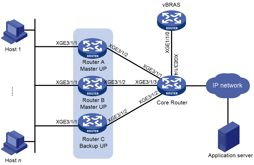
Table 8 Interface and IP address assignment
|
Device |
Interface |
IP address |
Device |
Interface |
IP address |
|
Router A |
XGE3/1/2 |
20.1.1.1 |
Router B |
XGE3/1/2 |
30.1.1.1 |
|
|
Loop1 |
8.1.2.1 |
|
Loop1 |
8.1.2.2 |
|
|
Loop2 |
99.1.1.1 |
|
Loop2 |
99.1.2.1 |
|
Router C |
XGE3/1/2 |
40.1.1.1 |
Core Router |
XGE3/1/1 |
20.1.1.2 |
|
|
Loop1 |
8.1.2.3 |
|
XGE3/1/3 |
30.1.1.2 |
|
|
Loop2 |
99.1.3.1 |
|
XGE3/1/2 |
40.1.1.2 |
|
vBRAS |
XGE1/1/0 |
110.1.1.20 |
|
XGE3/1/4 |
110.1.1.10 |
|
|
Loop1 |
8.1.1.1 |
|
Loop2 |
99.1.1.2 |
Prerequisites
Assign IP addresses to interfaces.
Establish management channels, control channels, and protocol channels between the CP and UP devices. Each UP device uses the IP address of interface LoopBack 1 to establish a CUSP connection with IP address 8.1.1.1 on the CP device. For more information, see CP and UP connection management configuration in CP and UP Separation Configuration Guide.
Procedure
1. Configure Router A:
¡ Configure a work mode for Router A.
# Configure Router A to operate in user mode.
[RouterA] work-mode user-plane
¡ Configure a failover group:
# Create failover group 1, and assign the CGN card in the specified slot to the failover group.
[RouterA] failover group 1 id 1
[RouterA-failover-group-1] bind slot 3 primary
# Create failover group 2, and assign the CGN card in the specified slot to the failover group.
[RouterA] failover group 2 id 2
[RouterA-failover-group-2] bind slot 4 primary
¡ Create a user group:
# Create user group user.
[RouterA] user-group user
[RouterA-ugroup-user] quit
¡ Configure a NAT address group:
# Create NAT address group 1.
[RouterA] nat address-group 1
# Configure port block parameters and set the port block size to 1000.
[RouterA-address-group-1] port-block block-size 1000
[RouterA-address-group-1] port-range 20000 40000
[RouterA-address-group-1] quit
¡ Configure a service instance group:
# Create service instance group 2 and enter its view.
[RouterA] service-instance-group 2
# Associate service instance group 2 with failover group 1 and failover group 2, respectively.
[RouterA-service-instance-group-2]
failover-group 1
[RouterA-service-instance-group-2]
failover-group 2
[RouterA-service-instance-group-2] quit
¡ Configure an advanced ACL:
# Create IPv4 advanced ACL 3000.
[RouterA] acl advanced 3000
# Configure a rule to permit only packets of users in user group user.
[RouterA-acl-ipv4-adv-3000] rule permit ip user-group user
[RouterA-acl-ipv4-adv-3000] quit
¡ Configure a dynamic global address pool:
# Create a dynamic global address pool named pool1.
[RouterA] nat ip-pool pool1 dynamic
# Bind global address pool pool1 to DHCP pool pool.
[RouterA-nat-ip-pool-pool1] bind dhcp-server-pool pool
¡ Configure a NAT instance:
# Create a NAT instance named aaa with ID 1.
[RouterA] nat instance aaa id 1
# Associate NAT instance aaa with service instance group 2.
[RouterA-nat-instance-aaa] service-instance-group 2
# Configure outbound dynamic NAT to use NAT address group 1 to translate packets permitted by ACL 3000.
[RouterA-nat-instance-aaa] nat outbound 3000 address-group 1
# Bind NAT address group 1 to global address pool pool1.
[RouterA-nat-instance-aaa] nat address-group 1 bind-ip-pool pool1
# Configure the load balancing mode for CGN warm backup.
[RouterA-nat-instance-aaa] cu warm-load-balance-mode enable
¡ Configure VSRP.
# Create VSRP peer 1. Configure the local address of the VSRP as 99.1.1.1 and the peer address as 99.1.2.1.
[RouterA] vsrp peer 1
[RouterA-vsrp-peer-1] peer 99.1.2.1 local 99.1.1.1 port 13000
[RouterA-vsrp-peer-1] quit
# Create VSRP peer 2. Configure the local address of the VSRP as 99.1.1.1 and the peer address as 99.1.3.1.
[RouterA] vsrp peer 2
[RouterA-vsrp-peer-2] peer 99.1.3.1 local 99.1.1.1 port 13000
[RouterA-vsrp-peer-2] quit
# Create VSRP instance 1 and set its backup ID to 1. Associate it with VSRP peer 1.
[RouterA] vsrp instance 1
[RouterA-vsrp-instance-1] backup id 1 peer 1
[RouterA-vsrp-instance-1] quit
# Create VSRP instance 2 and set its backup ID to 2. Associate it with VSRP peer 2.
[RouterA] vsrp instance 2
[RouterA-vsrp-instance-2] backup id 2 peer 2
[RouterA-vsrp-instance-2] quit
# Bind NAT instance aaa to VSRP instance 1 and VSRP instance 2, respectively.
[RouterA] nat instance aaa
[RouterA-nat-instance-aaa] bind vsrp-instance 1
[RouterA-nat-instance-aaa] bind vsrp-instance 2
[RouterA-nat-instance-aaa] quit
¡ Configure IS-IS:
# Enable IS-IS process 1 and set the system ID to 0000.0000.0001 and area ID to 00.
[RouterA] isis 1
[RouterA-isis-1] network-entity 00.0000.0000.0002.00
# Configure the router to receive and send only wide cost style packets.
[RouterA-isis-1] cost-style wide
# Enable IS-IS NSR.
[RouterA-isis-1] non-stop-routing
# Configure direct and UNR route redistributions.
[RouterA-isis-1] address-family ipv4 unicast
[RouterA-isis-1-ipv4] import-route direct inherit-cost
[RouterA-isis-1-ipv4] import-route unr inherit-cost
[RouterA-isis-1-ipv4] quit
[RouterA-isis-1] quit
# Enable IS-IS on Ten-GigabitEthernet 3/1/2 and LoopBack 2, and enable BFD on Ten-GigabitEthernet 3/1/2.
[RouterA] interface ten-gigabitethernet 3/1/2
[RouterA-Ten-GigabitEthernet3/1/2] isis enable 1
[RouterA-Ten-GigabitEthernet3/1/2] isis bfd enable
[RouterA-Ten-GigabitEthernet3/1/2] quit
[RouterA] interface loopback 2
[RouterA-LoopBack2] isis enable 1
¡ Configure static routing:
# Configure static routing.
[RouterA] ip route-static 8.1.1.1 32 20.1.1.2
¡ Configure track entries.
# Create track entry 1 and associate it with failover group 1.
[RouterA] track 1 failover-group 1
# Create track entry 2 and associate it with failover group 2.
[RouterA] track 2 failover-group 2
# Create track entry 100 of the Boolean type list to monitor track objects 1 and 2.
[RouterA] track 100 list boolean or
[RouterA-track-100] object 1
[RouterA-track-100] object 2
# Associate the UP with track entry 100.
[RouterA]user-plane switchover track 100 uplink-group up-1024
# Associate track entry 150 with BFD to monitor the interface on the public network side.
[RouterA] track 150 bfd echo interface GigabitEthernet1/0/2 remote ip 20.1.1.2 local ip 20.1.1.1
# Disable master/backup interface switchover on the UP.
[RouterA] user-plane control-tunnel-down switchover track 150
2. Configure Router B:
¡ Configure a work mode for Router B.
# Configure Router A to operate in user mode.
[RouterB] work-mode user-plane
¡ Configure a failover group:
# Create failover group 2, and assign the CGN card in the specified slot to the failover group.
[RouterB] failover group 2 id 2
[RouterB-failover-group-2] bind slot 4 primary
[RouterB-failover-group-2] quit
¡ Create a user group:
# Create user group user.
[RouterB] user-group user
[RouterB-ugroup-user] quit
¡ Configure a NAT address group:
# Create NAT address group 1.
[RouterB] nat address-group 1
# Configure port block parameters and set the port block size to 1000.
[RouterB-address-group-1] port-block block-size 1000
[RouterB-address-group-1] port-range 20000 40000
[RouterB-address-group-1] quit
¡ Configure a service instance group:
# Create service instance group 2 and enter its view.
[RouterB] service-instance-group 2
# Associate service instance group 2 with failover group 2.
[RouterB-service-instance-group-2] failover-group 2
[RouterB-service-instance-group-2] quit
¡ Configure an advanced ACL:
# Create IPv4 advanced ACL 3000.
[RouterB] acl advanced 3000
# Configure a rule to permit only packets of users in user group user.
[RouterB-acl-ipv4-adv-3000] rule permit ip user-group user
[RouterB-acl-ipv4-adv-3000] quit
¡ Configure a dynamic global address pool:
# Create a dynamic global address pool named pool1.
[RouterB] nat ip-pool pool1 dynamic
# Bind global address pool pool1 to DHCP pool pool.
[RouterB-nat-ip-pool-pool1] bind dhcp-server-pool pool
¡ Configure a NAT instance:
# Create a NAT instance named aaa with ID 1.
[RouterB] nat instance aaa id 1
# Associate NAT instance aaa with service instance group 2.
[RouterB-nat-instance-aaa] service-instance-group 2
# Configure outbound dynamic NAT to use NAT address group 1 to translate packets permitted by ACL 3000.
[RouterB-nat-instance-aaa] nat outbound 3000 address-group 1
# Bind NAT address group 1 to global address pool pool1.
[RouterB-nat-instance-aaa] nat address-group 1 bind-ip-pool pool1
# Configure the load balancing mode for CGN warm backup.
[RouterB-nat-instance-aaa] cu warm-load-balance-mode enable
¡ Configure VSRP.
# Create VSRP peer 1. Configure the local address of the VSRP as 99.1.2.1 and the peer address as 99.1.1.1.
[RouterB] vsrp peer 1
[RouterB-vsrp-peer-1] peer 99.1.1.1 local 99.1.2.1 port 13000
[RouterB-vsrp-peer-1] quit
# Create VSRP peer 2. Configure the local address of the VSRP as 99.1.2.1 and the peer address as 99.1.3.1.
[RouterB] vsrp peer 2
[RouterB-vsrp-peer-2] peer 99.1.3.1 local 99.1.2.1 port 13000
[RouterB-vsrp-peer-2] quit
# Create VSRP instance 1 and set its backup ID to 1. Associate it with VSRP peer 1.
[RouterB] vsrp instance 1
[RouterB-vsrp-instance-1] backup id 1 peer 1
[RouterB-vsrp-instance-1] quit
# Create VSRP instance 2 and set its backup ID to 3. Associate it with VSRP peer 2.
[RouterB] vsrp instance 2
[RouterB-vsrp-instance-2] backup id 3 peer 2
[RouterB-vsrp-instance-2] quit
# Bind NAT instance aaa to VSRP instance 1 and VSRP instance 2, respectively.
[RouterB] nat instance aaa
[RouterB-nat-instance-aaa] bind vsrp-instance 1
[RouterB-nat-instance-aaa] bind vsrp-instance 2
[RouterB-nat-instance-aaa] quit
¡ Configure IS-IS:
# Enable IS-IS process 1 and set the system ID to 0000.0000.0001 and area ID to 00.
[RouterB] isis 1
[RouterB-isis-1] network-entity 00.0000.0000.0002.00
# Configure the router to receive and send only wide cost style packets.
[RouterB-isis-1] cost-style wide
# Enable IS-IS NSR.
[RouterB-isis-1] non-stop-routing
# Configure direct and UNR route redistributions.
[RouterB-isis-1] address-family ipv4 unicast
[RouterB-isis-1-ipv4] import-route direct inherit-cost
[RouterB-isis-1-ipv4] import-route unr inherit-cost
[RouterB-isis-1-ipv4] quit
[RouterB-isis-1] quit
# Enable IS-IS on Ten-GigabitEthernet 3/1/2 and LoopBack 2, and enable BFD on Ten-GigabitEthernet 3/1/2.
[RouterB] interface ten-gigabitethernet 3/1/2
[RouterB-Ten-GigabitEthernet3/1/2] isis enable 1
[RouterB-Ten-GigabitEthernet3/1/2] isis bfd enable
[RouterB-Ten-GigabitEthernet3/1/2] quit
[RouterB] interface loopback 2
[RouterB-LoopBack2] isis enable 1
¡ Configure static routing:
# Configure static routing.
[RouterB] ip route-static 8.1.1.1 32 30.1.1.2
¡ Configure track entries.
# Create track entry 1 and associate it with failover group 1.
[RouterB] track 1 failover-group 1
# Create track entry 100 of the Boolean type list to monitor track object 1.
[RouterB] track 100 list boolean or
[RouterB-track-100] object 1
# Associate the UP with track entry 100.
[RouterB] user-plane switchover track 100 uplink-group up-1025
# Associate track entry 150 with BFD to monitor the interface on the public network side.
[RouterB] track 150 bfd echo interface GigabitEthernet1/0/2 remote ip 30.1.1.2 local ip 30.1.1.1
# Disable master/backup interface switchover on the UP.
[RouterB] user-plane control-tunnel-down switchover track 150
3. Configure Router C:
¡ Configure a work mode for Router C.
# Configure Router C to operate in user mode.
[RouterC] work-mode user-plane
¡ Configure a failover group:
# Create failover group 2, and assign the CGN card in the specified slot to the failover group.
[RouterC] failover group 2 id 2
[RouterC-failover-group-2] bind slot 4 primary
[RouterC-failover-group-2] quit
¡ Create a user group:
# Create user group user.
[RouterC] user-group user
[RouterC-ugroup-user] quit
¡ Configure a NAT address group:
# Create NAT address group 1.
[RouterC] nat address-group 1
# Configure port block parameters and set the port block size to 1000.
[RouterC-address-group-1] port-block block-size 1000
[RouterC-address-group-1] port-range 20000 40000
[RouterC-address-group-1] quit
¡ Configure a service instance group:
# Create service instance group 2 and enter its view.
[RouterC] service-instance-group 2
# Associate service instance group 2 with failover group 2.
[RouterC-service-instance-group-2] failover-group 2
[RouterC-service-instance-group-2] quit
¡ Configure an advanced ACL:
# Create IPv4 advanced ACL 3000.
[RouterC] acl advanced 3000
# Configure a rule to permit only packets of users in user group user.
[RouterC-acl-ipv4-adv-3000] rule permit ip user-group user
[RouterC-acl-ipv4-adv-3000] quit
¡ Configure a dynamic global address pool:
# Create a dynamic global address pool named pool1.
[RouterC] nat ip-pool pool1 dynamic
# Bind global address pool pool1 to DHCP pool pool.
[RouterC-nat-ip-pool-pool1] bind dhcp-server-pool pool
[RouterC-nat-ip-pool-pool1] quit
¡ Configure a NAT instance:
# Create a NAT instance named aaa with ID 1.
[RouterC] nat instance aaa id 1
# Associate NAT instance aaa with service instance group 2.
[RouterC-nat-instance-aaa] service-instance-group 2
# Configure outbound dynamic NAT to use NAT address group 1 to translate packets permitted by ACL 3000.
[RouterC-nat-instance-aaa] nat outbound 3000 address-group 1
# Bind NAT address group 1 to global address pool pool1.
[RouterC-nat-instance-aaa] nat address-group 1 bind-ip-pool pool1
# Configure the load balancing mode for CGN warm backup.
[RouterC-nat-instance-aaa] cu warm-load-balance-mode enable
[RouterC-nat-instance-aaa] quit
¡ Configure VSRP.
# Create VSRP peer 1. Configure the local address of the VSRP as 99.1.3.1 and the peer address as 99.1.1.1.
[RouterC] vsrp peer 1
[RouterC-vsrp-peer-1] peer 99.1.1.1 local 99.1.3.1 port 13000
[RouterC-vsrp-peer-1] quit
# Create VSRP peer 2. Configure the local address of the VSRP as 99.1.3.1 and the peer address as 99.1.2.1.
[RouterC] vsrp peer 2
[RouterC-vsrp-peer-2] peer 99.1.2.1 local 99.1.3.1 port 13000
[RouterC-vsrp-peer-2] quit
# Create VSRP instance 1 and set its backup ID to 2. Associate it with VSRP peer 1.
[RouterC] vsrp instance 1
[RouterC-vsrp-instance-1] backup id 2 peer 1
[RouterC-vsrp-instance-1] quit
# Create VSRP instance 2 and set its backup ID to 3. Associate it with VSRP peer 2.
[RouterC] vsrp instance 2
[RouterC-vsrp-instance-2] backup id 3 peer 2
[RouterC-vsrp-instance-2] quit
# Bind NAT instance aaa to VSRP instance 1 and VSRP instance 2, respectively.
[RouterC] nat instance aaa
[RouterC-nat-instance-aaa] bind vsrp-instance 1
[RouterC-nat-instance-aaa] bind vsrp-instance 2
[RouterC-nat-instance-aaa] quit
¡ Configure IS-IS:
# Enable IS-IS process 1 and set the system ID to 0000.0000.0003 and area ID to 00.
[RouterC] isis 1
[RouterC-isis-1] network-entity 00.0000.0000.0003.00
# Configure the router to receive and send only wide cost style packets.
[RouterC-isis-1] cost-style wide
# Enable IS-IS NSR.
[RouterC-isis-1] non-stop-routing
# Configure direct and UNR route redistributions.
[RouterC-isis-1] address-family ipv4 unicast
[RouterC-isis-1-ipv4] import-route direct inherit-cost
[RouterC-isis-1-ipv4] import-route unr inherit-cost
[RouterC-isis-1-ipv4] quit
[RouterC-isis-1] quit
# Enable IS-IS on Ten-GigabitEthernet 3/1/2 and LoopBack 2, and enable BFD on Ten-GigabitEthernet 3/1/2.
[RouterC] interface ten-gigabitethernet 3/1/2
[RouterC-Ten-GigabitEthernet3/1/2] isis enable 1
[RouterC-Ten-GigabitEthernet3/1/2] isis bfd enable
[RouterC-Ten-GigabitEthernet3/1/2] quit
[RouterC] interface loopback 2
[RouterC-LoopBack2] isis enable 1
¡ Configure static routing:
# Configure static routing.
[RouterC] ip route-static 8.1.1.1 32 40.1.1.2
¡ Configure track entries.
# Create track entry 1 and associate it with failover group 1.
[RouterC] track 1 failover-group 1
# Create track entry 100 of the Boolean type list to monitor track object 1.
[RouterC] track 100 list boolean or
[RouterC-track-100] object 1
# Associate the UP with track entry 100.
[RouterC] user-plane switchover track 100 uplink-group up-1026
# Associate track entry 150 with BFD to monitor the interface on the public network side.
[RouterC] track 150 bfd echo interface GigabitEthernet1/0/2 remote ip 40.1.1.2 local ip 40.1.1.1
# Disable master/backup interface switchover on the UP.
[RouterC] user-plane control-tunnel-down switchover track 150
4. Configure the core router:
¡ Configure IS-IS:
# Enable IS-IS process 1 and set the system ID to 0000.0000.0004 and area ID to 00.
# Configure the router to receive and send only wide cost style packets.
[CoreRouter-isis-1] cost-style wide
# Enable direct and UNR route redistribution.
[CoreRouter-isis-1] address-family ipv4 unicast
[CoreRouter-isis-1-ipv4] import-route direct
[CoreRouter-isis-1-ipv4] import-route unr
# Enable FRR for IS-IS process 1 and configure IS-IS FRR to calculate a backup next hop through LFA calculation for all routes.
[CoreRouter-isis-1-ipv4] fast-reroute lfa
[CoreRouter-isis-1-ipv4] quit
[CoreRouter-isis-1] quit
# Enable IS-IS on Ten-GigabitEthernet 3/1/1, Ten-GigabitEthernet 3/1/2, Ten-GigabitEthernet 3/1/3, and LoopBack 2, and configure BFD on Ten-GigabitEthernet 3/1/1, Ten-GigabitEthernet 3/1/2, and Ten-GigabitEthernet 3/1/3.
[CoreRouter] interface ten-gigabitethernet 3/1/1
[CoreRouter-Ten-GigabitEthernet3/1/1] isis enable 1
[CoreRouter-Ten-GigabitEthernet3/1/1] isis bfd enable
[CoreRouter-Ten-GigabitEthernet3/1/1] bfd min-transmit-interval 10
[CoreRouter-Ten-GigabitEthernet3/1/1] bfd min-receive-interval 10
[CoreRouter-Ten-GigabitEthernet3/1/1] bfd detect-multiplier 3
[CoreRouter-Ten-GigabitEthernet3/1/1] quit
[CoreRouter] interface ten-gigabitethernet 3/1/2
[CoreRouter-Ten-GigabitEthernet3/1/2] isis enable 1
[CoreRouter-Ten-GigabitEthernet3/1/2] isis bfd enable
[CoreRouter-Ten-GigabitEthernet3/1/2] quit
[CoreRouter] interface ten-gigabitethernet 3/1/3
[CoreRouter-Ten-GigabitEthernet3/1/3] isis enable 1
[CoreRouter-Ten-GigabitEthernet3/1/3] isis bfd enable
[CoreRouter-Ten-GigabitEthernet3/1/3] quit
[CoreRouter] interface loopback2
[CoreRouter-LoopBack2] isis enable 1
[CoreRouter-LoopBack2] quit
5. Configure the vBRAS device.
¡ Configure a NAT instance:
# Create a NAT instance named aaa with ID 1.
[vBRAS] nat instance aaa id 1
[vBRAS-nat-instance-aaa] quit
¡ Configure an ODAP IP pool for user address assignment:
# Create an IP pool that assigns IP addresses to ODAP access users, and specify the gateway address 10.210.0.0/16 and subnet mask length 24. Configure the IP pool to allocate subnets by UP backup profile ID.
[vBRAS] ip pool userpool odap
[vBRAS-ip-pool-userpool] network 10.210.0.0 16 export-route
[vBRAS-ip-pool-userpool] subnet mask-length 24
[vBRAS-ip-pool-userpool] subnet alloc-mode up-backup-profile
[vBRAS-ip-pool-userpool] quit
¡ Configure a NAT-central IP pool for user address assignment:
# Create a NAT-central IP pool that assigns IP addresses to NAT-central access users, and specify the gateway address 200.1.0.0/20 and subnet mask length 32.
[vBRAS] ip pool pool nat-central
[vBRAS-ip-pool-pool] network 200.1.0.0 mask 255.255.240.0
[vBRAS-ip-pool-pool] subnet mask-length 32
[vBRAS-ip-pool-pool] quit
¡ Configure an ISP domain.
# Create an ISP domain named cgn.
[vBRAS] domain name cgn
# Specify RADIUS scheme rad for PPP user authentication, authorization, and accounting.
[vBRAS-isp-cgn] authentication ppp radius-scheme rad
[vBRAS-isp-cgn] authorization ppp radius-scheme rad
[vBRAS-isp-cgn] accounting ppp radius-scheme rad
[vBRAS-isp-cgn] authorization-attribute ip-pool userpool
# Specify the user address type as private IPv4 address.
[vBRAS-isp-cgn] user-address-type private-ipv4
[vBRAS-isp-cgn] quit
¡ Bind a user group to the NAT instance:
# Create a user group named user.
[vBRAS] user-group user
[vBRAS-ugroup-user] quit
# Bind user group user to NAT instance aaa.
[vBRAS] domain name cgn
[vBRAS-isp-cgn] user-group user bind nat-instance aaa
[vBRAS-isp-cgn] quit
¡ Configure an advanced ACL:
# Create IPv4 advanced ACL 3000.
[vBRAS] acl advanced 3000
# Configure a rule to permit only packets of users in user group user.
[vBRAS-acl-ipv4-adv-3000] rule permit ip user-group user
[vBRAS-acl-ipv4-adv-3000] quit
¡ Configure a QoS policy to redirect IP packets of user group user to the NAT instance:
# Configure traffic class c1 to match IP packets of users in user group user.
[vBRAS] traffic classifier c1
[vBRAS-classifier-c1] if-match acl 3000
[vBRAS-classifier-c1] quit
# Configure traffic behavior b1 to bind the matching traffic to NAT instance aaa.
[vBRAS] traffic behavior b1
[vBRAS-behavior-b1] bind nat-instance aaa
[vBRAS-behavior-b1] quit
# Create QoS policy cb1 and associate the traffic class with the traffic behavior.
[vBRAS] qos policy cb1
[vBRAS-qospolicy-cb1] classifier c1 behavior b1
[vBRAS-qospolicy-cb1] quit
# Apply QoS policy cb1 to the inbound traffic on Remote-XGE1024/3/1/1.
[vBRAS] interface Remote-GE1024/1/0/1
[vBRAS-Remote-XGE1024/3/1/1] qos apply policy cb1 inbound
[vBRAS-Remote-XGE1024/3/1/1] quit
# Apply QoS policy cb1 to the inbound traffic on Remote-XGE1025/3/1/1.
[vBRAS] interface Remote-GE1025/1/0/1
[vBRAS-Remote-XGE1025/3/1/1] qos apply policy cb1 inbound
[vBRAS-Remote-XGE1025/3/1/1] quit
# Apply QoS policy cb1 to the inbound traffic on Remote-XGE1026/3/1/1.
[vBRAS] interface Remote-GE1026/1/0/1
[vBRAS-Remote-XGE1026/3/1/1] qos apply policy cb1 inbound
[vBRAS-Remote-XGE1026/3/1/1] quit
¡ Configure a UP backup profile:
# Create warm-standby UP backup profile 3.
[vBRAS] up-backup-profile 3 warm-load-balance
# Enable IP address advertisement on the master and backup interfaces.
[vBRAS-up-backup-profile-3] backup route-advertise
# Configure the switchover delay upon CUSP channel failure as 10 seconds.
[vBRAS-up-backup-profile-3] control-tunnel-down switchover delay 10
# Configure the master/backup switchover delay as 100 seconds for the UP backup profile.
[vBRAS-up-backup-profile-4] failure-recovery-switch enable delay 100
# Enable the CP to monitor the CGN state of UP1024, UP1025, and UP1026.
[vBRAS-up-backup-profile-4] up-id 1024 network-state track uplink-group up-1024
[vBRAS-up-backup-profile-4] up-id 1025 network-state track uplink-group up-1025
[vBRAS-up-backup-profile-4] up-id 1026 network-state track uplink-group up-1026
# Specify the master interfaces for the UP backup profile.
[vBRAS-up-backup-profile-1] master-interface remote-xge 1024/3/1/1 vrid 1
[vBRAS-up-backup-profile-1] master-interface remote-xge 1025/3/1/1 vrid 2
[vBRAS-up-backup-profile-1] master-interface remote-xge 1025/3/1/1 vrid 3
¡ Configure the PPPoE server:
# Configure Virtual-Template 1 to use PAP for authentication.
[vBRAS] interface virtual-template1
[vBRAS-Virtual-Template1] ppp authentication-mode pap domain cgn
[vBRAS-Virtual-Template1] quit
# Enable the PPPoE server on Remote-XGE1024/3/1/1, and bind the interface to Virtual-Template 1.
[vBRAS] interface remote-xge 1024/3/1/1
[vBRAS-Remote-XGE1024/3/1/1] pppoe-server bind virtual-template 1
[vBRAS-Remote-XGE1024/3/1/1] quit
# Enable the PPPoE server on Remote-XGE1025/3/1/1, and bind the interface to Virtual-Template 1.
[vBRAS] interface remote-xge 1025/3/1/1
[vBRAS-Remote-XGE1025/3/1/1] pppoe-server bind virtual-template 1
[vBRAS-Remote-XGE1025/3/1/1] quit
# Enable the PPPoE server on Remote-XGE1026/3/1/1, and bind the interface to Virtual-Template 1.
[vBRAS] interface remote-xge 1026/3/1/1
[vBRAS-Remote-XGE1026/3/1/1] pppoe-server bind virtual-template 1
[vBRAS-Remote-XGE1026/3/1/1] quit
¡ Configure static routing:
[vBRAS] ip route-static 0.0.0.0 0.0.0.0 110.1.1.10
Verifying the configuration
# On Router A, display NAT statistics to verify that a dynamic port block entry has been created on slot 3.
[RouterA] display nat statistics summary
EIM: Total EIM entries.
SPB: Total static port block entries.
DPB: Total dynamic port block entries.
ASPB: Active static port block entries.
ADPB: Active dynamic port block entries.
Slot Sessions EIM SPB DPB ASPB ADPB
0 0 0 0 0 0 0
3 0 0 0 40 0 1
4 0 0 0 20 0 0
5 0 0 0 0 0 0
# Verify that the user can access the network from the PPPoE dialup software on a host.
# On the vBRAS device, display allocation statistics about subnets that are requested from the DHCP pool.
[vBRAS] display nat dhcp-server-pool-alloc statistics
DHCP server IP pool allocation statistics for NAT:
Totally 1 DHCP server IP pools.
Pool name: pool
Subnet count: 4
UPID Subnet Mask
------------------------------------------
1024 200.1.0.0 255.255.255.255
1024 200.1.0.1 255.255.255.255
1024 200.1.0.2 255.255.255.255
1024 200.1.0.3 255.255.255.255
# On Router A, display information about global address pool pool1 to verify that the pool has obtained public IP addresses from the CP device.
[RouterA] display nat ip-pool
NAT IP pool information:
Totally 1 NAT ip pools.
Pool name : pool1
Type of pool : Dynamic
DHCP pool name : pool
UPID (Local/Peer) : -/-
Subnet length (Initial/Extended): 27/27
Usage thresholds (High/Low) : 80%/20%
Instance name/ID : aaa/1
Totally 1 sub NAT IP pools.
Pool name : Sub_196610_pool1
UPID (Local/Peer) : 1024/1025
Instance name/ID : Sub_196610_aaa/129
Total IP count : 4
Available IP count : 1
Usage : 75%
Section info:
ID Subnet Mask Total Used
-----------------------------------------------------------
0 200.1.0.0 255.255.255.255 1 1
1 200.1.0.1 255.255.255.255 1 1
2 200.1.0.2 255.255.255.255 1 1
3 200.1.0.3 255.255.255.255 1 0
# On Router A, display the number of assignable dynamic port blocks and the number of assigned dynamic port blocks.
[RouterA] display nat statistics slot 3
Slot 3:
Total session entries: 0
Total EIM entries: 0
Total inbound NO-PAT entries: 0
Total outbound NO-PAT entries: 0
Total static port block entries: 0
Total dynamic port block entries: 40
Active static port block entries: 0
Active dynamic port block entries: 1
Total PAT entries: 0
[RouterA] display nat statistics slot 4
Slot 4:
Total session entries: 0
Total EIM entries: 0
Total inbound NO-PAT entries: 0
Total outbound NO-PAT entries: 0
Total static port block entries: 0
Total dynamic port block entries: 20
Active static port block entries: 0
Active dynamic port block entries: 0
Total PAT entries: 0
# On Router B, display information about dynamic global address pool pool1 to verify that the pool has obtained IP addresses from the master UP device.
[RouterB] display nat ip-pool
NAT IP pool information:
Totally 1 NAT ip pools.
Pool name : pool1
Type of pool : Dynamic
DHCP pool name : pool
UPID (Local/Peer) : -/-
Subnet length (Initial/Extended): 27/27
Usage thresholds (High/Low) : 80%/20%
Instance name/ID : aaa/1
Totally 1 sub NAT IP pools.
Pool name : Sub_196610_pool1
UPID (Local/Peer) : 1024/1025
Instance name/ID : Sub_196610_aaa/129
Total IP count : 4
Available IP count : 1
Usage : 75%
Section info:
ID Subnet Mask Total Used
-----------------------------------------------------------
0 200.1.0.0 255.255.255.255 1 1
1 200.1.0.1 255.255.255.255 1 1
2 200.1.0.2 255.255.255.255 1 1
3 200.1.0.3 255.255.255.255 1 0
# On Router B, display the number of assignable dynamic port blocks and the number of assigned dynamic port blocks.
[RouterB] display nat statistics slot 4
Slot 4:
Total session entries: 0
Total EIM entries: 0
Total inbound NO-PAT entries: 0
Total outbound NO-PAT entries: 0
Total static port block entries: 0
Total dynamic port block entries: 60
Active static port block entries: 0
Active dynamic port block entries: 0
Total PAT entries: 0
