- Table of Contents
-
- 17-BRAS Services Configuration Guide
- 00-Preface
- 01-AAA configuration
- 02-ANCP configuration
- 03-PPP configuration
- 04-Value-added services configuration
- 05-DHCP configuration
- 06-DHCPv6 configuration
- 07-User profile configuration
- 08-Connection limit configuration
- 09-L2TP configuration
- 10-PPPoE configuration
- 11-IPoE configuration
- 12-802.1X configuration
- 13-UCM configuration
- Related Documents
-
| Title | Size | Download |
|---|---|---|
| 10-PPPoE configuration | 960.91 KB |
Contents
Restrictions and guidelines: PPPoE configuration
PPPoE server tasks at a glance in common mode
PPPoE server tasks at a glance in CUPS mode
Configuring the device to operate in user plane mode
Configuring CP-UP connection management
Setting the maximum number of PPPoE sessions
Limiting the PPPoE access rate
Configuring the NAS-Port-ID attribute
Configuring NAS-Port-ID binding for PPPoE access users
Setting a service name for the PPPoE server
Setting the maximum number of PADI packets that the device can receive per second (unified devices)
Setting maximum number of PADI packets that each slot of a UP can receive per second
Configuring PPPoE user blocking
Configuring PPPoE protocol packet attack prevention
Forbidding PPPoE users from coming online through an interface
PPPoE agency tasks at a glance
Configuring the PPPoE agency forwarding policy
Configuring the authentication domain for PPPoE agency users
Enabling the PPPoE agency on an interface
Configuring the PPPoE agency logging feature
Display and maintenance commands for PPPoE
Display and maintenance commands for PPPoE server
Display and maintenance commands for PPPoE agency
PPPoE configuration examples(on unified network)
Example: Configuring the PPPoE server to assign IPv4 addresses through the local DHCP server
Example: Configuring the PPPoE server to assign IPv6 addresses through the IA_NA method
Example: Configuring the PPPoE server to assign IPv6 addresses through the IA_PD method
Example: Configuring the PPPoE server to assign IP addresses through the DHCPv4+NDRA+IA_PD method
Example: Configuring the PPPoE server to assign IPv6 addresses through the IA_NA+IA_PD method
Example: Assigning IP addresses to dual-stack users through the local DHCP server
Example: Configuring PPPoE server RADIUS-based IP address assignment
Example: Configuring PPPoE agency (authorizing a remote BAS IP address pool)
Example: Configuring PPPoE static dual-stack users
PPPoE configuration examples(on CUPS network)
Example: Configuring the PPPoE server to allocate IPv4 addresses through a local DHCP server
Example: Configuring the PPPoE server to assign IPv6 addresses through the IA_NA method
Example: Configuring the PPPoE server to assign IPv6 addresses through the IA_PD method
Example: Configuring the PPPoE server to assign IPv6 addresses through the IA_NA+IA_PD method
Configuring PPPoE
About PPPoE
Point-to-Point Protocol over Ethernet (PPPoE) extends PPP by transporting PPP frames encapsulated in Ethernet over point-to-point links.
PPPoE specifies the methods for establishing PPPoE sessions and encapsulating PPP frames over Ethernet. PPPoE requires a point-to-point relationship between peers instead of a point-to-multipoint relationship as in multi-access environments such as Ethernet. PPPoE provides Internet access for the hosts in an Ethernet through a remote access device and implement access control, authentication, and accounting on a per-host basis. Integrating the low cost of Ethernet and scalability and management functions of PPP, PPPoE gained popularity in various application environments, such as residential access networks.
For more information about PPPoE, see RFC 2516.
PPPoE network structure
PPPoE uses the client/server model. The PPPoE client initiates a connection request to the PPPoE server. After session negotiation between them is complete, a session is established between them, and the PPPoE server provides access control, authentication, and accounting to the PPPoE client.
PPPoE network structures are classified into router-initiated and host-initiated network structures depending on the starting point of the PPPoE session.
In this section, the network architecture is in common mode. When the network is in CP and UP separation (CUPS) mode, the PPPoE server contains a UP and a CP. For more information about UPs and CPs, see "PPPoE server operating modes."
Router-initiated network structure
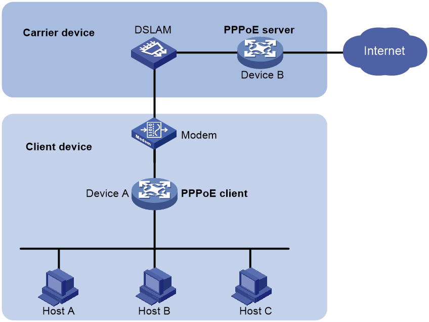
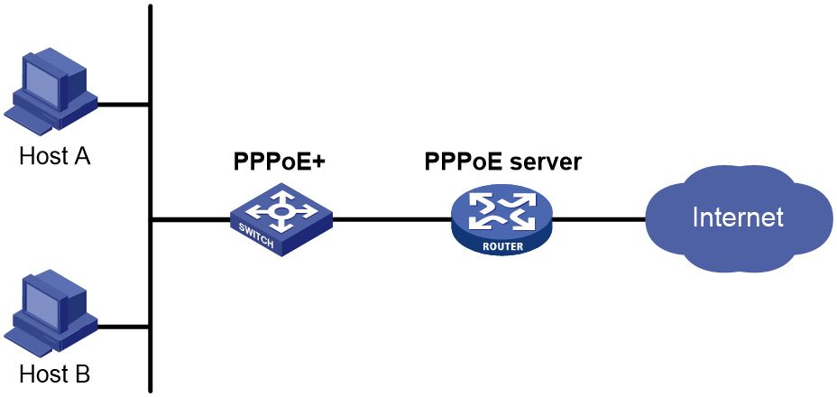
As shown in Figure 1, the PPPoE session is established between routers (Router A and Router B). All hosts share one PPPoE session for data transmission without being installed with PPPoE client software. This network structure is typically used by enterprises.
Figure 1 Router-initiated network structure
Host-initiated network structure
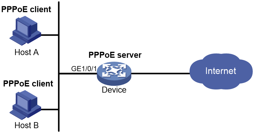
As shown in Figure 2, a PPPoE session is established between each host (PPPoE client) and the carrier router (PPPoE server). The service provider assigns an account to each host for billing and control. The host must be installed with PPPoE client software.
Figure 2 Host-initiated network structure
PPPoE agency
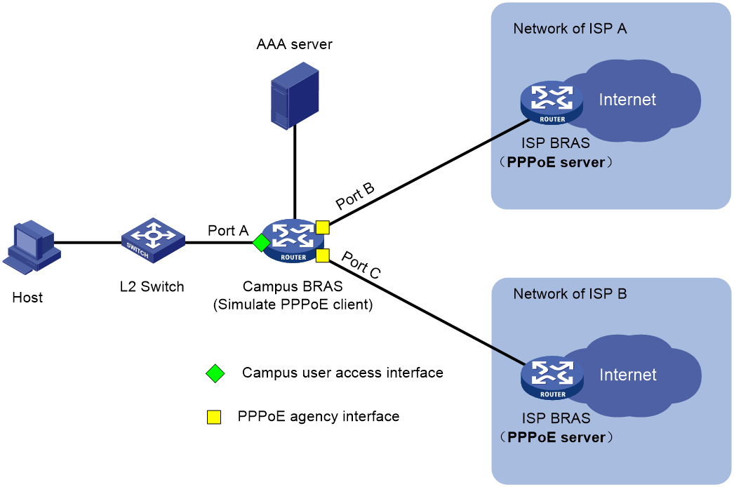
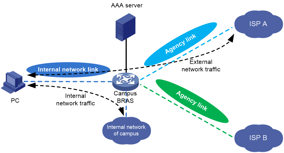
As shown in Figure 3, to provide diversified network egresses for campus users and simplify the construction and O&M for the campus network, more and more universities select to cooperate with the ISPs to construct campus networks. In this scenario, you can deploy the PPPoE agency on the campus BRASs to allow a campus user to freely select an ISP network and use the simulated PPPoE client to initiate PPPoE dialup for network access to the PPPoE server in the corresponding ISP network. This feature not only simplifies the joint operations between the universities and ISPs but also provides good network access experience for students.
Figure 3 Schematic diagram for PPPoE agency
Protocols and standards
RFC 2516: A Method for Transmitting PPP Over Ethernet (PPPoE)
Restrictions and guidelines: PPPoE configuration
When you configure the PPPoE server feature, follow these restrictions and guidelines:
· The device can only act as a PPPoE server, and cannot act as a PPPoE client (except the simulated PPPoE client on the PPPoE agency network).
· In standard system operating mode, this feature is available only for the following cards:
|
Card category |
Cards |
|
CEPC |
CEPC-XP4LX, CEPC-XP24LX, CEPC-XP48RX, CEPC-CP4RX, CEPC-CP4RXA, CEPC-CP4RX-L |
|
CSPEX |
CSPEX-1304X, CSPEX-1404X, CSPEX-1502X, CSPEX-1504X, CSPEX-1504XA, CSPEX-1602X, CSPEX-1602XA, CSPEX-1804X, CSPEX-1512X, CSPEX-1612X, CSPEX-1812X, CSPEX-1802X, CSPEX-1812X-E, CSPEX-2304X-G, CSPEX-1502XA |
|
SPE |
RX-SPE200, RX-SPE200-E |
· In SDN-WAN system operating mode, the device does not support this feature.
When you configure the PPPoE agency feature, follow these restrictions and guidelines:
· In standard system operating mode, this feature is available only for the following cards:
|
Card category |
Cards |
|
CSPEX |
CSPEX-1802X, CSPEX-1812X-E, CSPEX-2304X-G, CSPEX-1502XA |
|
SPE |
RX-SPE200-E |
· In SDN-WAN system operating mode, the device does not support this feature.
· To provide the PPPoE agency service for a campus user that is a Layer 3 IPoE user, you must execute the pppoe-server session-limit per-mac command on the PPPoE server of the ISP to configure the maximum number of PPPoE sessions for each user to be greater than the actual number of internal campus users. If you cannot do that, the PPPoE agency users cannot come online due to MAC address conflicts.
· Make sure the user group configured with the PPPoE agency feature is different from a user group in a rule of an ACL packet filter configured by using the packet-filter command. If you cannot do that, the PPPoE agency feature does not take effect.
· The PPPoE agency feature is supported only on unified networks, and is not supported on CUPS networks.
· Only the IPv4 multicast service supports the PPPoE agency feature. IPv6 and multicast do not support the PPPoE agency feature.
· In the PPPoE agency scenario, the PPPoE server on the ISP side supports only PAP and CHAP authentication methods, and does not support the MS-CHAP or MS-CHAPv2 authentication method.
· Both the access interfaces of agency gateways and the agency interfaces (in unified agency mode and agency gateway mode) only support Layer 3 Ethernet interfaces/subinterfaces and Layer 3 aggregate interfaces/subinterfaces. The access interfaces of agency gateways and the subinterfaces of agency interfaces must meet the following requirements:
¡ They support common VLAN termination, and do not support user VLAN termination.
¡ They support unambiguous dot1q termination and QinQ termination, and do not support ambiguous dot1q termination or QinQ termination.
¡ They do not support untagged termination or default termination.
In PPPoE applications, the advertisement pushing function takes effect only on HTTP packets with port number 80 or 8080.
When a PPPoE server acts as a DHCP relay agent, the following command settings must be the same on the DHCP relay agent and the remote DHCP server for a common IP address pool:
· In a DHCPv4 network:
¡ network: Specifies a network segment for dynamic allocation in an IP pool.
¡ address range: Configures an IP address range in an IP pool for dynamic allocation.
¡ forbidden-ip: Exclude IP addresses from dynamic allocation in an IP pool.
For more information about these commands, see BRAS Services Command Reference.
· In a DHCPv6 network:
¡ network: Specifies an IPv6 subnet for dynamic allocation in an IPv6 address pool.
¡ address range: Specifies a non-temporary IPv6 address range in an IPv6 address pool for dynamic allocation.
¡ forbidden-address: Excludes IPv6 addresses from dynamic allocation in an IPv6 address pool.
¡ forbidden-prefix: Excludes IPv6 prefixes from dynamic allocation in an IPv6 address pool.
¡ prefix-pool: Applies a prefix pool to an IPv6 address pool, so the DHCPv6 server can dynamically select a prefix from the prefix pool for a client.
For more information about these commands, see BRAS Services Command Reference.
Configuring the PPPoE server
PPPoE server operating modes
About CUPS
On a traditional BRAS, the control plane capabilities might not match the forwarding plane capabilities, the resources cannot be shared, and new services cannot be deployed in time. The vBRAS-based CUPS solution is introduced to solve this problem.
In this solution, the forwarding plane and control plane are completely decoupled and are independent of each other. The solution contains control plane (CP) roles and user plane (UP) roles, which together implement the BRAS functionality.
· CP—Performs control plane services, including user identification and address allocation and management. Typically, a CP is a vBRAS.
· UP—Performs the forwarding plane services, including data packet forwarding and traffic control. A UP can be a router, or vBRAS.
The following three channels are established between the CP and UP to implement CUPS.
· Management channel—Deploys configuration between the CP and UP.
· Control channel—Deploys entries between the CP and UP.
· Protocol tunnel—Transmits protocol packets between the CP and UP.
Operating modes
In a CUPS network, a BRAS can operate in one of the following modes:
· Common mode—A BRAS operating in this mode performs both control and forwarding services. A device operating in this mode is called a unified device.
· Control plane mode—Depending on how the CP function is implemented, this mode supports the following control modes:
¡ Session mode—This mode implements the CP function based on remote interfaces. When the UP connected to a CP supports PPPoE, you can configure the session mode. In this mode, the CP sends BRAS sessions to the UP. The UP performs data packet forwarding according to the received sessions. For more information about remote interfaces, see CP-UP connection management in the vBRAS-CP configuration guides.
· User plane mode—A BRAS operating in this mode performs only the forwarding service. A BRAS operating in user plane mode is a UP.
The control plane mode and user plane mode are collectively referred to as the CUPS mode.
|
|
NOTE: · Unless otherwise specified, a PPPoE server in this document refers to a PPPoE server operating in common mode. · In CUPS mode, the device can act only as a UP, and cannot act as a CP. |
PPPoE user access procedure (CP in session mode)
When the CP operates in session mode, the UP forwards the received authentication packets to the CP over the VXLAN tunnel for authentication and authorization. After the user passes authentication, the CP sets up a PPPoE session and delivers the PPPoE session and authorization information to the UP over the CUPS channel. Figure 4 shows the detailed process.
Figure 4 PPPoE user access procedure (CP in session mode)
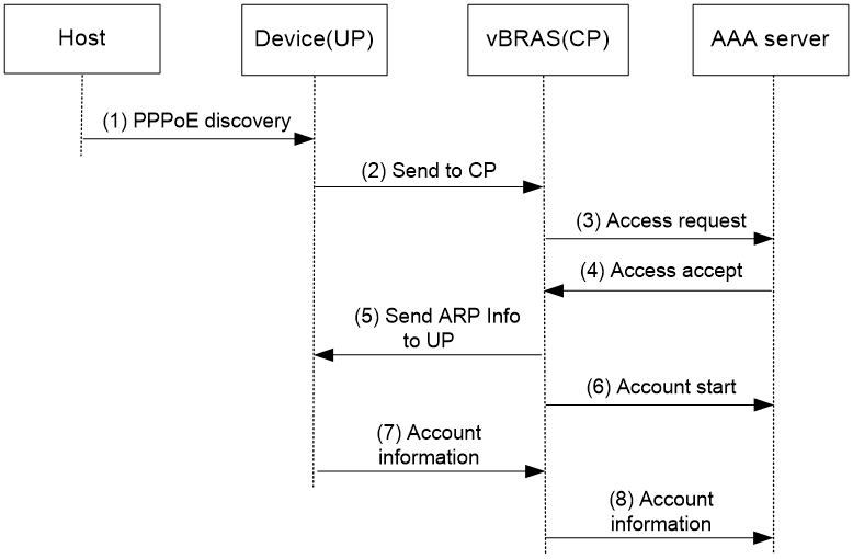
1. The host sends a PPPoE discovery packet (which refers to all packets during the discovery phase) to the UP.
2. The UP sends the packet to the CP over the VXLAN tunnel.
3. The CP creates a PPPoE session and performs PPP negotiation. The CP sends authentication requests to the AAA server. The authentication requests contain the username and password.
4. The AAA server returns the authentication result.
¡ If the user passes the authentication, the AAA server returns the Access-Accept packet carrying the authorization information. The CP performs NCP negotiation.
¡ If the user fails the authentication, the AAA server returns the Access-Reject packet. The user goes offline.
5. After the NCP negotiation succeeds, the CP sends the PPPoE session information to the UP over the CUPS channel.
6. The CP sends Accounting-Start packets to the AAA server. The AAA server starts accounting the user.
7. The UP periodically collects the user traffic, and sends the traffic to the CP over the CUPS channel.
8. The CP sends the traffic to the AAA server for accounting.
PPPoE server tasks at a glance in common mode
To configure PPPoE server in common mode, perform the following tasks:
1. Configuring a PPPoE session
2. (Optional.) Setting the maximum number of PPPoE sessions
3. (Optional.) Enabling PPPoE logging
4. (Optional.) Limiting the PPPoE access rate
5. (Optional.) Configuring the NAS-Port-ID attribute
6. Configuring NAS-Port-ID binding for PPPoE access users
Perform this task if you need to acquire the physical location of the PPPoE user access interface by NAS-Port-ID.
7. (Optional.) Setting a service name for the PPPoE server
8. (Optional.) Setting the maximum number of PADI packets that the device can receive per second
9. (Optional.) Configuring PPPoE user blocking
10. (Optional.) Configuring PPPoE protocol packet attack prevention
11. (Optional.) Forbidding PPPoE users from coming online through an interface
PPPoE server tasks at a glance in CUPS mode
In a CUPS network, the device can act only as a UP, and cannot act as a CP.
The configuration procedures on CPs in this section are for reference only. For more information, see manuals for devices acting as CPs.
UP tasks at a glance
To configure the UP when the CP connected to it operates in session mode, perform the following tasks:
1. Configuring the device to operate in user plane mode
2. Configuring CP-UP connection management
Configuring the device to operate in user plane mode
About this task
You must configure the device to operate in user plane mode when the following requirements are met:
· The PPPoE server is on a network in CUPS mode.
· The CP connected to the UP operates in session mode.
Procedure
1. Enter system view.
system-view
2. Configure the device to operate in user plane mode.
work-mode user-plane
By default, the device operates in common mode.
For more information about this command, see UCM in BRAS Services Command Reference.
Configuring CP-UP connection management
For more information, see CP-UP connection management in the vBRAS-CP configuration guides.
Configuring a PPPoE session
1. Enter system view.
system-view
2. Create a VT interface and enter VT interface view.
interface virtual-template number
3. Set PPP parameters.
For more information setting PPP parameters, see "Configuring PPP."
When configuring PPP authentication, use the PPPoE server as the authenticator.
4. Return to system view.
quit
5. Enter interface view.
interface interface-type interface-number
6. Enable the PPPoE server on the interface and bind this interface to the specified VT interface.
pppoe-server bind virtual-template number
By default, the PPPoE server is disabled on the interface.
7. (Optional.) Configure an access concentrator (AC) name for the PPPoE server.
pppoe-server tag ac-name name
By default, the AC name for the PPPoE server is the device name.
PPPoE clients can choose a PPPoE server according to the AC name.
8. (Optional.) Enable the PPPoE server to support the ppp-max-payload tag and specify a range for the PPP maximum payload.
pppoe-server tag ppp-max-payload [ minimum min-number maximum max-number ]
By default, The PPPoE server does not support the ppp-max-payload tag.
9. (Optional) Set the response delay time for user access.
pppoe-server access-delay delay-time [ even-mac | odd-mac ]
By default, no response delay time is set.
10. Return to system view.
quit
11. Configure the PPPoE server to perform authentication, authorization, and accounting for PPP users.
For more information, see BRAS Services Configuration Guide.
Setting the maximum number of PPPoE sessions
About this task
PPPoE can establish a session when none of the following limits are reached:
· Limit for a user on an interface.
· Limit for a VLAN on an interface.
· Limit on an interface.
· (In standalone mode.) (In IRF mode.) Limit on a card.
Restrictions and guidelines for maximum number of PPPoE sessions
If the configured limit is smaller than the number of existing online sessions on the interface, the configuration succeeds. The configuration does not affect the existing online sessions. However, new sessions cannot be established on the interface.
(In standalone mode.) (In IRF mode.) The total maximum number of PPPoE sessions set for all cards or IRF member devices cannot be greater than the maximum number of PPPoE sessions supported by the device.
Setting the maximum number of PPPoE sessions in interface view
1. Enter system view.
system-view
2. Enter interface view.
interface interface-type interface-number
The PPPoE server is enabled on the interface.
3. Set the maximum number of PPPoE sessions.
¡ Set the maximum number of PPPoE sessions on an interface.
pppoe-server session-limit number
By default, the number of PPPoE sessions on an interface is not limited.
¡ Set the maximum number of PPPoE sessions for a VLAN.
pppoe-server session-limit per-vlan number
By default, the number of PPPoE sessions for a VLAN on an interface is not limited.
¡ Set the maximum number of PPPoE sessions for a user.
pppoe-server session-limit per-mac number
By default, a user is allowed to create a maximum of 1 PPPoE sessions.
Setting the maximum number of PPPoE sessions in system view
1. Enter system view.
system-view
2. Set the maximum number of PPPoE sessions.
In standalone mode:
pppoe-server session-limit slot slot-number [ cpu cpu-number ] total number
In IRF mode:
pppoe-server session-limit chassis chassis-number slot slot-number [ cpu cpu-number ] total number
By default, the number of PPPoE sessions is not limited.
Enabling PPPoE logging
About this task
The PPPoE logging feature enables the device to generate PPPoE logs and send them to the information center. Logs are generated when the following requirements are met:
· The number of PPPoE sessions reaches the upper limit for an interface, user, VLAN, or the system.
· New users request to come online.
A log entry records the interface-based, MAC-based, VLAN-based, or system-based session limit. For information about the log destination and output rule configuration in the information center, see Network Management and Monitoring Configuration Guide.
Restrictions and guidelines
As a best practice, disable this feature to prevent excessive PPP log output.
Procedure
1. Enter system view.
system-view
2. Enable PPPoE logging.
pppoe-server log enable
By default, PPPoE logging is disabled.
Limiting the PPPoE access rate
About this task
The device can limit the rate at which a user (identified by an MAC address) can create PPPoE sessions on an interface. If the number of PPPoE requests within the monitoring time reaches the configured threshold, the device discards the excessive requests, and outputs log messages. If the blocking time is set to 0, the device does not block any requests, and it only outputs log messages.
The device uses a monitoring table and a blocking table to control PPP access rates:
· Monitoring table—Stores a maximum of 8000 monitoring entries. Each entry records the number of PPPoE sessions created by a user within the monitoring time. When the monitoring entries reach the maximum, the system stops monitoring and blocking session requests from new users. The aging time of monitoring entries is determined by the session-request-period argument. When the timer expires, the system starts a new round of monitoring for the user.
· Blocking table—Stores a maximum of 8000 blocking entries. The system creates a blocking entry if the access rate of a user reaches the threshold, and blocks requests from that user. When the blocking entries reach the maximum number, the system stops blocking session requests from new users and it only outputs log messages. The aging time of the blocking entries is determined by the blocking-period argument. When the timer expires, the system starts a new round of monitoring for the user.
Restrictions and guidelines
If the access rate setting is changed, the system removes all monitoring and blocking entries, and uses the new settings to limit PPPoE access rates.
Procedure
1. Enter system view.
system-view
2. Enter interface view.
interface interface-type interface-number
The PPPoE server is enabled on the interface.
3. Set the PPPoE access limit.
pppoe-server throttle per-mac session-requests session-request-period blocking-period
By default, the PPPoE access rate is not limited.
Configuring the NAS-Port-ID attribute
About this task
On a PPPoE+ network as shown in Figure 5 or a network containing a DSLAM device, the PPPoE server on a BRAS uses the RADIUS NAS-Port-ID attribute to copy and send the access line ID received from the PPPoE+ device (typically a switch with PPPoE+ deployed) or DSLAM device to the RADIUS server. The access line ID includes the circuit-id and remote-id. The RADIUS server compares the received NAS-Port-ID attribute with the local line ID information to verify the location of the user.
You can configure the content of the NAS-Port-ID attribute that the PPPoE server sends to the RADIUS server.
Figure 5 PPPoE+ network diagram
Restrictions and guidelines
If the attribute 87 format command is executed in RADIUS scheme view, the format of the NAS-Port-ID attribute sent to the RADIUS server is determined by using this command. In this case, the NAS-Port-ID attribute format defined in PPPoE does not take effect. For more information about the attribute 87 format command, see AAA commands in BRAS Services Command Reference.
Procedure
1. Enter system view.
system-view
2. Enter interface view.
interface interface-type interface-number
The PPPoE server is enabled on the interface.
Support for interface views depends on the device model.
3. Configure the content of the NAS-Port-ID attribute.
pppoe-server access-line-id content { all [ separator ] | circuit-id | remote-id }
By default, the NAS-Port-ID attribute contains only the circuit-id.
4. Configure the NAS-Port-ID attribute to include the BAS information automatically.
pppoe-server access-line-id bas-info [ cn-163 | cn-163-redback ]
By default, the NAS-Port-ID attribute does not include the BAS information automatically.
5. Configure the PPPoE server to trust the access line ID in received packets.
pppoe-server access-line-id trust
By default, the PPPoE server does not trust the access line ID in received packets.
6. Configure the transmission format for the circuit-id.
pppoe-server access-line-id circuit-id trans-format { ascii | hex }
The default format is a string of characters.
7. Configure the transmission format for the remote-id.
pppoe-server access-line-id remote-id trans-format { ascii | hex }
The default format is a string of characters.
8. Insert the VXLAN information into the NAS-Port-ID attribute.
pppoe-server access-line-id vxlan-info enable
By default, VXLAN information is not inserted into the NAS-Port-ID attribute.
Configuring NAS-Port-ID binding for PPPoE access users
About this task
a device uses information about the interface through which a user comes online to fill in the NAS-Port-ID attribute and sends it to the RADIUS server by default. In some special applications, when you need to manually specify the access interface information to be filled in the NAS-Port-ID attribute, you can use this command. For example, suppose the RADIUS server restricts user A's access to only interface A. When user A accesses through interface B and you do not want to modify the RADIUS server configuration, you can execute this command to use information about interface A to fill in the NAS-Port-ID attribute for user A and send the attribute to the RADIUS server.
When the BAS information format is China-Telecom 163 and the pppoe-server nas-port-id interface command is executed, the following rules apply:
· If the access-user four-dimension-mode enable command is also specified, the interface information specified in the pppoe-server nas-port-id interface command will be used to fill in the following access interface information field in the NAS-PORT-ID attribute:
¡ On a non-CUPS network: chassis=NAS_chassis;slot=NAS_slot;subslot=NAS_subslot;port=NAS_port.
¡ On a CUPS network: chassis=UP_ID;slot=NAS_slot;subslot=NAS_subslot;port=NAS_port.
· If the access-user four-dimension-mode enable command is not executed, the interface information specified in the pppoe-server nas-port-id interface command will be used to fill in the following access interface information field in the NAS-PORT-ID attribute: slot=NAS_slot;subslot=NAS_subslot;port=NAS_port.
When the BAS information format is China-Telecom and the pppoe-server nas-port-id interface command is executed, the following rules apply:
· If the access-user four-dimension-mode enable command is also executed, the interface information specified in the pppoe-server nas-port-id interface command will be used to fill in the following NAS information field in the NAS-PORT-ID attribute:
¡ On a non-CUPS network: {eth|trunk|atm} NAS_chassis/NAS_slot/NAS_subslot/NAS_port.
¡ On a CUPS network: {eth|trunk|atm} UP_ID/NAS_slot/NAS_subslot/NAS_port.
· If the access-user four-dimension-mode enable command is not executed, the interface information specified in the pppoe-server nas-port-id interface command will be used to fill in the following access interface information field in the NAS-PORT-ID attribute: {eth|trunk|atm} NAS_slot/NAS_subslot/NAS_port.
Restrictions and guidelines
If the attribute 87 format command is executed in RADIUS scheme view, the format of the NAS-Port-ID attribute sent to the RADIUS server is determined by using this command. In this case, the NAS-Port-ID attribute format defined in PPPoE does not take effect. For more information about the attribute 87 format command, see AAA commands in BRAS Command Reference.
This feature takes effect only when the corresponding interface is configured to automatically include BAS information in the NAS-Port-ID attribute by using the pppoe-server access-line-id bas-info command.
The information configured in this feature is also used to fill in the NAS-Port attribute.
Procedure
1. Enter system view.
system-view
2. Enter interface view.
interface interface-type interface-number
3. Configure the CP to use information of the specified interface on a UP to fill in the NAS-Port-ID attribute.
pppoe-server nas-port-id interface interface-type interface-number
By default, the CP uses information about the interface through which the user comes online to fill in the NAS-Port-ID attribute.
In a CUPS network, the interface specified in this command must be the access interface of PPPoE users on the UP. The interface number is in the format of UP Id/actual interface number on the UP. For example, if a user accesses through Ten-GigabitEthernet 3/1/1 on UP 1024, the interface number specified in this command must be 1024/3/1/1.
Setting a service name for the PPPoE server
About this task
Upon receiving a PADI or a PADR packet from a PPPoE client, the PPPoE server compares its service name with the service-name tag field of the packet. The server accepts the session establishment request only if the field matches the service name. Table 1 describes different matching rules in different matching modes.
Table 1 Service name matching rules
|
Matching mode |
PPPoE client |
PPPoE server |
Result |
|
Exact match |
No service name is specified. |
The number of configured service names is less than 8. |
Success |
|
The number of configured service names is 8. |
Failure |
||
|
A service name is specified. |
A service name that is the same as that of the client is configured. |
Success |
|
|
A service name that is the same as that of the client is not configured. |
Failure |
||
|
Fuzzy match |
No service name is specified. |
Any configuration. |
Success |
|
A service name is specified. |
A service name that is the same as that of the client is configured, or the number of configured service names is less than 8. |
Success |
|
|
A service name that is the same as that of the client is not configured, or the number of configured service names is 8. |
Failure |
Restrictions and guidelines
Service names identify the traffic destined for PPPoE servers when multiple PPPoE servers are providing services on the network.
You can configure a maximum of 8 service names on an interface.
Procedure
1. Enter system view.
system-view
2. Enter interface view.
interface interface-type interface-number
3. Configure the service name matching mode for the PPPoE server as exact match.
pppoe-server service-name-tag exact-match
By default, the service name matching mode for the PPPoE server is fuzzy match..
4. Set a service name for the PPPoE server.
pppoe-server tag service-name name
By default, the PPPoE server does not have a service name.
Setting the maximum number of PADI packets that the device can receive per second (unified devices)
About this task
When device reboot or version update is performed, the burst of online requests might affect the device performance. To avoid device performance degradation and make sure the device can process PADI packets correctly, use this feature to adjust the PADI packet receiving rate limit.
Restrictions and guidelines
Table 2 Default settings for the PADI packet receiving rate limit
|
MPU model |
PADI packet receiving rate limit |
|
CSR05SRP1L1 CSR05SRP1L3 CSR05SRP1P3 CSR05SRP1R3 CSR05SRP1R3A CSR05SRP1P3-G |
500 |
|
Other MPUs |
200 |
Procedure
1. Enter system view.
system-view
2. Set the maximum number of PADI packets that the LNS can receive per second.
In standalone mode:
pppoe-server padi-limit slot slot-number [ cpu cpu-number ] number
In IRF mode:
pppoe-server padi-limit chassis chassis-number slot slot-number [ cpu cpu-number ] number
The default varies by MPU model. For more information, see the preceding table.
Setting maximum number of PADI packets that each slot of a UP can receive per second
About this task
In the CUPS scenario, when device reboot or version update is performed, the burst of online requests might affect the device performance. To avoid device performance degradation and make sure the device can process PADI packets correctly, use this command to adjust the PADI packet receiving rate limit on each slot of a UP.
Procedure
1. Enter system view.
system-view
2. Set the maximum number of PADI packets that each slot of a UP can receive per second.
pppoe-server padi-limit per-slot number
The default is 2000.
Configuring PPPoE user blocking
About this task
You can use this feature to prevent multiple PPPoE users from frequently coming online and going offline or prevent protocol packet attacks. After this feature is enabled, users who performs the following operations for the specified number of times within a period will be blocked:
· Come online.
· Go offline.
· Send PPPoE connection requests.
Packets from blocked users will be discarded during the blocking period, and will be processed after the blocking period expires. At the same time, the device still performs PPPoE user blocking detection for PPPoE users within the blocking period. If the number of discarded packets meets the formula (number of discarded packets × request-period ≥requests × blocking-period) before the blocking period expires, the PPPoE users will be blocked for one more blocking period.
User blocking includes MAC-based user blocking and option105-based user blocking.
Restrictions and guidelines for PPPoE user blocking configuration
· If you enable this feature in system view, the feature applies to all PPPoE users.
· If you enable this feature in interface view, the feature applies to PPPoE users accessing the interface.
· If you execute this command in both system view and interface view, a user is monitored by blocking conditions in both views. When the user meets the blocking conditions in any view first, the user is blocked by the blocking settings in the view.
· If you enable MAC-based user blocking, the device uniquely identifies a blocked user by using its MAC address, the outermost VLAN ID, and the access interface.
· If you enable option105-based user blocking, the device uniquely identifies a blocked user by using its circuit ID, remote ID, and the access interface.
· In the unified scenario, when the blocking conditions are met, blocking entries are generated only for the slots hosting interfaces actually receiving packets. For example, when a user accessing a Layer 3 aggregate interface meets the blocking conditions, the blocking entries are generated only on the slots hosting member ports of the Layer 3 aggregate interface.
· In the CUPS scenario, the following rules apply when the blocking conditions are met:
¡ MAC-based PPPoE user blocking—For a user accessing a global interface on a UP, the blocking entries are generated on the master BRAS-VM managing the UP and all slots of the UP. For a user accessing a local interface on a UP, the blocking entries are generated on the master BRAS-VM managing the UP and the slot hosting the local interface on the UP.
¡ Option 105-based PPPoE user blocking—For a user accessing a global interface or local interface on a UP, the blocking entries are generated on the master BRAS-VM managing the UP but not on the UP.
Enabling MAC-based user blocking in system view
1. Enter system view.
system-view
2. Enable MAC-based user blocking.
pppoe-server connection chasten [ quickoffline ] [ multi-sessions-permac ] requests request-period blocking-period
By default, a MAC-based PPPoE user will be blocked for 300 seconds if the user fails authentication consecutively for 120 times within 60 seconds.
Enabling MAC-based user blocking in interface view
1. Enter system view.
system-view
2. Enter interface view.
interface interface-type interface-number
The PPPoE server is enabled on the interface.
Support for interface views depends on the device model.
3. Enable MAC-based user blocking.
pppoe-server connection chasten [ quickoffline ] [ multi-sessions-permac ] requests request-period blocking-period
By default, MAC-based user blocking is disabled.
Enabling option105-based user blocking in system view
1. Enter system view.
system-view
2. Enable option105-based user blocking.
pppoe-server connection chasten option105 [ quickoffline ] requests request-period blocking-period
By default, option105-based user blocking is disabled.
Enabling option105-based user blocking in interface view
1. Enter system view.
system-view
2. Enter interface view.
interface interface-type interface-number
The PPPoE server is enabled on the interface.
Support for interface views depends on the device model.
3. Enable option105-based user blocking.
pppoe-server connection chasten option105 [ quickoffline ] requests request-period blocking-period
By default, option105-based user blocking is disabled.
Configuring PPPoE protocol packet attack prevention
About this task
In the Discovery phase of the PPPoE link establishment process, the PPPoE client sends PADI or PADR packets to find the PPPoE server that can provide the access service. After the PPPoE session is established, the PPPoE client can send PADT packets at any time to terminate the PPPoE session.
To prevent a large number of users frequently coming online and going offline or illegal users from initiating protocol packet attacks, which will occupy a large number of system resources, you can configure the PPPoE protocol packet attack prevention feature. With this feature configured, if the number of protocol packets that the PPPoE server receives within the detection interval exceeds the specified number, the PPPoE protocol packets received from the interface will be rate-limited. During the rate-limiting period, the excess PPPoE protocol packets are dropped. At the same time, the device still performs attack prevention detection for the interface within the rate-limiting period. If the number of PPPoE protocol packets dropped meets the formula (number of dropped packets × interval ≥ number ×rate-limit-period) before the rate-limiting period expires, one more rate-limiting period is added. After the rate-limiting period expires, the rate-limiting on the PPPoE protocol packets received from the interface is cancelled.
Restrictions and guidelines
You can configure PPPoE protocol packet attack prevention in system view and in interface view. The configuration in system view takes effect on all interfaces, and the configuration in interface view takes effect only on the current interface. If you configure this feature both in system view and interface view, the configuration in interface view takes priority.
Configuring PPPoE protocol packet attack prevention globally
1. Enter system view.
system-view
2. Enable PPPoE protocol packet attack prevention.
pppoe-server connection chasten per-interface number interval rate-limit-period
By default, PPPoE protocol packet attack prevention is disabled.
Configuring PPPoE protocol packet attack prevention on an interface
1. Enter system view.
system-view
2. Enter interface view.
interface interface-type interface-number
Make sure the interface has PPPoE server enabled.
3. Enable PPPoE protocol packet attack prevention.
pppoe-server connection chasten per-interface number interval rate-limit-period
By default, PPPoE protocol packet attack prevention is disabled.
Forbidding PPPoE users from coming online through an interface
About this task
With this feature configured on an interface, the interface directly drops received PADI and PADR packets to forbid users from coming online through this interface.
Restrictions and guidelines
This feature does not affect existing PPPoE users.
Procedure
1. Enter system view.
system-view
2. Enter interface view.
interface interface-type interface-number
3. Forbid PPPoE users from coming online through the interface.
pppoe-server block
By default, PPPoE users are permitted to come online.
Configuring the PPPoE agency
PPPoE agency tasks at a glance
To configure PPPoE agency, perform the following tasks:
1. Configuring the PPPoE agency forwarding policy
2. Configuring the authentication domain for PPPoE agency users
3. Enabling the PPPoE agency on an interface
4. (Optional.) Configuring the PPPoE agency logging feature
Configuring the PPPoE agency forwarding policy
About this task
As shown in the following diagram, for an IPoE or PPPoE user in the campus network, if the AAA server of the campus network assigns the user a user group configured with a PPPoE agency forwarding policy when the user performs authentication, the user has the requirements to access the external network. The BRAS needs to perform PPPoE agency for the user according to the following process:
1. After the user passes authentication to come online, the BRAS will maintain the intra-campus access authentication user information for the campus user and also mark the user as a PPPoE agency user. That is, if a campus user also has an agency account, the BRAS will maintain two identities for the user.
¡ The BRAS processes the internal network traffic of the user in the traffic processing method for the access authentication user when the user comes online (for example, IPoE user) and directly forwards the internal network traffic.
¡ The BRAS processes the external network traffic of the user in the traffic processing method for the PPPoE agency user.
2. When the AAA server receives the Accounting-Start packets from a campus BRAS, the AAA server will send the COA messages to notify the campus BRAS to start the PPPoE agency process for the accounting user. The COA messages carry the ISP account opened for the user and the Frame-Pool attribute with the value as the PPPoE agency group name.
3. When the campus BRAS receives the COA messages, the BRAS simulates a PPPoE client and initiates PPPoE dialup to the PPPoE server of the corresponding ISP according to the account and PPPoE agency group name carried in the COA messages.
4. When the BRAS receives data traffic from the PPPoE agency user that has successfully comes online, the BRAS will consider the traffic that does not match the ACL in the PPPoE agency forwarding policy as the external network traffic and send the external network traffic to the corresponding ISP for processing.
Figure 6 Schematic diagram for PPPoE agency
Restrictions and guidelines
If a campus BRAS receives the external network traffic of a PPPoE agency user before the campus BRAS initiates PPPoE dialup for network access to the PPPoE server of the corresponding ISP, the campus BRAS directly drops the traffic.
In the current software version, only IPoE individual users and PPPoE users support the PPPoE agency feature. Among these users, IPoE Web individual users support the PPPoE agency feature only in the postauthentication phase, and do not support the PPPoE agency feature in the preauthentication phase.
Procedure
1. Enter system view.
system-view
2. Create a user group and enter its view.
user-group group-name
By default, the user group named system exists.
For more information about this command, see AAA commands in BRAS Services Command Reference.
3. Configure a PPPoE agency forwarding policy.
pppoe-agency forward { ipv4 | ipv6 } acl { acl-number | name acl-name }
By default, no PPPoE agency forwarding policy is configured.
Configuring the authentication domain for PPPoE agency users
About this task
When a campus BRAS simulates a PPPoE client and initiates PPPoE dialup for network access to the PPPoE server of the corresponding ISP according to the PPPoE agency group name carried in the COA messages, the BRAS first authenticates the PPPoE agency user according to the authentication domain specified in the pppoe-agency authentication domain command. If no authentication domain is specified by the pppoe-agency authentication domain command or the specified authentication domain does not exist, the BRAS uses the authentication domain selected by the AAA module. PPPoE agency can succeed only when the campus BRAS successfully authenticates the PPPoE agency user and the ISP PPPoE server successfully authenticates the PPPoE client. If the authentication on any end fails, PPPoE agency fails. In this case, the user can access only the internal network, and cannot access the external network.
Procedure
1. Enter system view.
system-view
2. Create a user group and enter its view.
user-group group-name
By default, the user group named system exists.
For more information about this command, see AAA commands in BRAS Services Command Reference.
3. Configure the authentication domain for PPPoE agency users.
pppoe-agency authentication domain domain-name
By default, no authentication domain is configured for PPPoE agency users.
Enabling the PPPoE agency on an interface
About this task
With this feature configured, when a campus BRAS user initiates the agency process, the campus BRAS will select one interface that matches the PPPoE agency group name carried in COA messages from the interfaces with the pppoe-agency bind command executed (PPPoE agency interfaces), and use the interface to simulate a PPPoE client and initiate PPPoE dialup for network access to the PPPoE server of the corresponding ISP.
If the PPPoE agency group name carried in the COA messages authorized to a user matches the pppoe-agency-group-name argument value configured on multiple interfaces, the device will select the interface with the least online PPPoE agency users to simulate a PPPoE client for the user to perform PPPoE agency dialup.
Restrictions and guidelines
If an interface has the PPPoE agency enabled and is bound to a VT interface, you cannot directly use this command to bind the interface to a new VT interface. To do that, first disable the PPPoE agency on the interface, and then re-enable the PPPoE agency on the interface and bind it to a new VT interface.
When the PPPoE agency is enabled on an interface, the VT interface bound to the interface must exist.
If both the PPPoE client and PPPoE agency are enabled on an interface, the PPPoE client does not take effect.
When the device is configured to operate in user plane mode by using the work-mode user-plane command, you cannot enable the PPPoE agency on any interface of the device.
On an interface, the pppoe-server bind command and the pppoe-agency bind command are mutually exclusive.
Procedure
1. Enter system view.
system-view
2. Enter interface view.
interface interface-type interface-number
3. Enable the PPPoE agency on an interface and bind the interface to a PPPoE agency group.
pppoe-agency bind virtual-template number pppoe-agency-group pppoe-agency-group-name
By default, the PPPoE agency is disabled on an interface.
Configuring the PPPoE agency logging feature
About this task
You can enable the PPPoE agency logging feature to meet the security audit (for example, source tracing) requirements. This feature records the mappings between the internal IP addresses of internal campus users and the IP addresses that ISPs allocate to PPPoE agency users.
With this feature enabled, when a PPPoE agency user comes online, the BRAS in the campus will generate log messages about the mapping between the internal IP address of the internal campus user and the IP address that the ISP allocates to the PPPoE agency user. The generated PPPoE agency log messages by the device will be sent to the information center. The information center configuration specifies the log message sending rule and destination. For more information about the information center, see Network Management and Monitoring Configuration Guide.
Restrictions and guidelines
To prevent the device from generating too many PPPoE agency logs, as a best practice, disable this feature typically.
Procedure
1. Enter system view.
system-view
2. Enable the PPPoE agency logging feature.
pppoe-agency log enable
By default, the PPPoE agency logging feature is disabled.
Display and maintenance commands for PPPoE
Display and maintenance commands for PPPoE server
Execute display commands in any view and reset commands in user view.
|
Task |
Command |
|
Display PPPoE user blocking configuration information. |
display pppoe-server chasten configuration [ global | interface interface-type interface-number ] |
|
Display the PPPoE protocol packet attack prevention entries. |
In standalone mode: display pppoe-server chasten per-interface [ interface interface-type interface-number ] [ slot slot-number [ cpu cpu-number ] ] In IRF mode: display pppoe-server chasten per-interface [ interface interface-type interface-number ] [ chassis chassis-number slot slot-number [ cpu cpu-number ] ] |
|
Display the PPPoE protocol packet attack prevention configuration information. |
display pppoe-server chasten per-interface configuration [ interface interface-type interface-number ] |
|
Display statistics about PPPoE user blocking. |
In standalone mode: display pppoe-server chasten statistics [ mac-address | option105 ] [ interface interface-type interface-number ] [ slot slot-number [ cpu cpu-number ] ] In IRF mode: display pppoe-server chasten statistics [ mac-address | option105 ] [ interface interface-type interface-number ] [ chassis chassis-number slot slot-number [ cpu cpu-number ] ] |
|
Display information about blocked PPPoE users. |
In standalone mode: display pppoe-server chasten user [ mac-address [ mac-address ] | option105 [ circuit-id circuit-id ] [ remote-id remote-id ] ] [ interface interface-type interface-number ] [ slot slot-number [ cpu cpu-number ] ] [ verbose ] In IRF mode: display pppoe-server chasten user [ mac-address [ mac-address ] | option105 [ circuit-id circuit-id ] [ remote-id remote-id ] ] [ interface interface-type interface-number ] [ chassis chassis-number slot slot-number [ cpu cpu-number ] ] [ verbose ] |
|
Display PPPoE server negotiation packet statistics. |
In standalone mode: display pppoe-server packet statistics [ slot slot-number [ cpu cpu-number ] ] In IRF mode: display pppoe-server packet statistics [ chassis chassis-number slot slot-number [ cpu cpu-number ] ] |
|
Display summary information for PPPoE sessions. |
In standalone mode: display pppoe-server session summary [ [ interface interface-type interface-number | slot slot-number [ cpu cpu-number ] ] | mac-address mac-address ] * In IRF mode: display pppoe-server session summary [ [ interface interface-type interface-number | chassis chassis-number slot slot-number [ cpu cpu-number ] ] | mac-address mac-address ] * |
|
Display information about blocked users. |
In standalone mode: display pppoe-server throttled-mac { slot slot-number [ cpu cpu-number ] | interface interface-type interface-number } In IRF mode: display pppoe-server throttled-mac { chassis chassis-number slot slot-number [ cpu cpu-number ] | interface interface-type interface-number } |
|
Clear PPPoE sessions. |
reset pppoe-server { all | [ interface interface-type interface-number | mac-address mac-address ] * | virtual-template number } |
|
Clear PPPoE protocol packet attack prevention entry information. |
In standalone mode: reset pppoe-server chasten per-interface [ packets ] [ interface interface-type interface-number ] [ slot slot-number [ cpu cpu-number ] ] In IRF mode: reset pppoe-server chasten per-interface [ packets ] [ interface interface-type interface-number ] [ chassis chassis-number slot slot-number [ cpu cpu-number ] ] |
|
Clear information of blocked PPPoE users. |
In standalone mode: reset pppoe-server chasten user [ packets ] [ mac-address [ mac-address ] | option105 [ circuit-id circuit-id ] [ remote-id remote-id ] ] [ interface interface-type interface-number ] [ slot slot-number [ cpu cpu-number ] ] In IRF mode: reset pppoe-server chasten user [ packets ] [ mac-address [ mac-address ] | option105 [ circuit-id circuit-id ] [ remote-id remote-id ] ] [ interface interface-type interface-number ] [ chassis chassis-number slot slot-number [ cpu cpu-number ] ] |
|
Clear PPPoE server negotiation packet statistics. |
In standalone mode: reset pppoe-server packet statistics [ slot slot-number [ cpu cpu-number ] ] In IRF mode: reset pppoe-server packet statistics [ chassis chassis-number slot slot-number [ cpu cpu-number ] ] |
Display and maintenance commands for PPPoE agency
Execute display commands in any view and reset commands in user view.
|
Task |
Command |
|
Display statistics of packets matching ACLs in the PPPoE agency application. |
In standalone mode: display pppoe-agency { ipv4 | ipv6 } acl statistics user-group user-group-name slot slot-number [ cpu cpu-number ] In IRF mode: display pppoe-agency { ipv4 | ipv6 } acl statistics user-group user-group-name chassis chassis-number slot slot-number [ cpu cpu-number ] |
|
Display the PPPoE agency negotiation packet statistics. |
In standalone mode: display pppoe-agency packet statistics [ slot slot-number [ cpu cpu-number ] ] In IRF mode: display pppoe-agency packet statistics [ chassis chassis-number slot slot-number [ cpu cpu-number ] ] |
|
Display summary information of the PPPoE agency user sessions. |
In standalone mode: display pppoe-agency session summary [ interface interface-type interface-number | slot slot-number [ cpu cpu-number ] ] In IRF mode: display pppoe-agency session summary [ interface interface-type interface-number | chassis chassis-number slot slot-number [ cpu cpu-number ] ] |
|
Clear the PPPoE agency sessions on the PPPoE agency. |
reset pppoe-agency { all | interface interface-type interface-number | virtual-template number } |
|
Clear statistics of packets matching ACLs in the PPPoE agency application. |
In standalone mode: reset pppoe-agency { ipv4 | ipv6 } acl statistics user-group user-group-name slot slot-number [ cpu cpu-number ] In IRF mode: reset pppoe-agency { ipv4 | ipv6 } acl statistics user-group user-group-name chassis chassis-number slot slot-number [ cpu cpu-number ] |
|
Clear the PPPoE agency negotiation packet statistics. |
In standalone mode: reset pppoe-agency packet statistics [ slot slot-number [ cpu cpu-number ] ] In IRF mode: reset pppoe-agency packet statistics [ chassis chassis-number slot slot-number [ cpu cpu-number ] ] |
PPPoE configuration examples(on unified network)
Example: Configuring the PPPoE server to assign IPv4 addresses through the local DHCP server
Network configuration
As shown in Figure 7, configure the PPPoE server as a DHCP server to assign an IP address to the host.

Procedure
# Configure Virtual-Template 1 to use CHAP for authentication.
<Router> system-view
[Router] interface virtual-template 1
[Router-Virtual-Template1] ppp authentication-mode chap domain dm1
# Enable the PPPoE server on Ten-GigabitEthernet 3/1/1, and bind the interface to Virtual-Template 1.
[Router] interface ten-gigabitethernet 3/1/1
[Router-Ten-GigabitEthernet3/1/1] pppoe-server bind virtual-template 1
[Router-Ten-GigabitEthernet3/1/1] quit
# Enable DHCP.
[Router] dhcp enable
# Configure local BAS IP address pool pool1.
[Router] ip pool pool1 bas local
[Router-ip-pool-pool1] gateway 1.1.1.1 24
[Router-ip-pool-pool1] dns-list 8.8.8.8
# Exclude the IP address 1.1.1.1 from dynamic allocation in IP address pool pool1.
[Router-ip-pool-pool1] forbidden-ip 1.1.1.1
[Router-ip-pool-pool1] quit
# Create a PPPoE user.
[Router] local-user user1 class network
[Router-luser-network-user1] password simple 123456TESTplat&!
[Router-luser-network-user1] service-type ppp
[Router-luser-network-user1] quit
# In ISP domain dm1, perform local AAA for PPP users and authorize an address pool.
[Router] domain name dm1
[Router-isp-dm1] authentication ppp local
[Router-isp-dm1] accounting ppp local
[Router-isp-dm1] authorization ppp local
[Router-isp-dm1] authorization-attribute ip-pool pool1
[Router-isp-dm1] quit
Verifying the configuration
# Log in to the router by using username user1 and password 123456TESTplat&!.
# Display information about IP addresses assigned by the DHCP server.
[Router] display access-user interface ten-gigabitethernet 3/1/1
Username Access type
IPv6 address
0xc XGE3/1/1 1.1.1.2 001b-21a8-0949 -/-
user1 PPPoE
-
The output shows that the router has assigned an IP address to the host.
Example: Configuring the PPPoE server to assign IP addresses to dual-stack users through a remote DHCP server
Network configuration
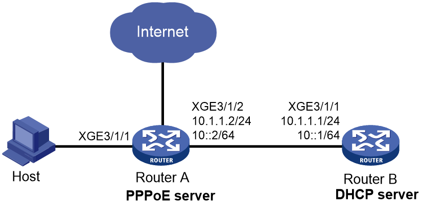
As shown in Figure 8, configure the PPPoE server as a DHCP relay agent to relay an IPv4 address and an IPv6 address from the DHCP server to the host.
Prerequisites
Assign IP addresses to interface, and make sure the devices can reach each other at Layer 3. (Details not shown.)
Procedure
1. Configure Router A as the PPPoE server:
# Configure Virtual-Template 1 to use CHAP for authentication.
<RouterA> system-view
[RouterA] interface virtual-template 1
[RouterA-Virtual-Template1] ppp authentication-mode chap domain dm1
# Enable Virtual-Template 1 to advertise RA messages.
[RouterA-Virtual-Template1] undo ipv6 nd ra halt
# Set the managed address configuration flag (M) to 1 in RA advertisements to be sent on Virtual-Template 1.
[RouterA-Virtual-Template1] ipv6 nd autoconfig managed-address-flag
# Set the other stateful configuration flag (O) to 1 in RA advertisements to be sent on Virtual-Template 1.
[RouterA-Virtual-Template1] ipv6 nd autoconfig other-flag
[RouterA-Virtual-Template1] quit
# Enable the PPPoE server on Ten-GigabitEthernet 3/1/1, and bind the interface to Virtual-Template 1.
[RouterA] interface ten-gigabitethernet 3/1/1
[RouterA-Ten-GigabitEthernet3/1/1] pppoe-server bind virtual-template 1
[RouterA-Ten-GigabitEthernet3/1/1] quit
# Enable DHCP.
[RouterA] dhcp enable
# Create remote BAS IP address pool pool1.
[RouterA] ip pool pool1 bas remote
# Specify a gateway address for the clients in pool1.
[RouterA-ip-pool-pool1] gateway 1.1.1.1 24
# Exclude IP address 1.1.1.1 from dynamic allocation in pool1.
[RouterA-ip-pool-pool1] forbidden-ip 1.1.1.1
# Specify a DHCP server for pool1.
[RouterA-ip-pool-pool1] remote-server 10.1.1.1
[RouterA-ip-pool-pool1] quit
# Create an IPv6 address pool named pool2.
[RouterA] ipv6 pool pool2
# Specify gateway address 1::1 for DHCPv6 clients in the IPv6 address pool.
[RouterA-ipv6-pool-pool2] gateway-list 1::1
# Specify the subnet 1::/64 for dynamic allocation in the IPv6 address pool.
[RouterA-ipv6-pool-pool2] network 1::/64 export-route
# Exclude IPv6 address 1::1 from dynamic allocation in the IPv6 address pool.
[RouterA-ipv6-pool-pool2] forbidden-address 1::1
# Specify DHCPv6 server 10::1 for the IPv6 address pool.
[RouterA-ipv6-pool-pool2] remote-server 10::1
[RouterA-ipv6-pool-pool2] quit
# Enable the DHCPv4 relay agent and DHCPv6 relay agent on Ten-GigabitEthernet 3/1/1.
[RouterA] interface ten-gigabitethernet 3/1/1
[RouterA–Ten-GigabitEthernet3/1/1] dhcp select relay
[RouterA–Ten-GigabitEthernet3/1/1] ipv6 dhcp select relay
[RouterA–Ten-GigabitEthernet3/1/1] ipv6 dhcp relay release-agent
# Configure Ten-GigabitEthernet 3/1/1 to automatically generate a link-local address, which is to be used as the gateway of users.
[RouterA–Ten-GigabitEthernet3/1/1] ipv6 address auto link-local
# Enable Ten-GigabitEthernet 3/1/1 to advertise RA messages.
[RouterA–Ten-GigabitEthernet3/1/1] undo ipv6 nd ra halt
[RouterA–Ten-GigabitEthernet3/1/1] quit
# Create a PPPoE user.
[RouterA] local-user user1 class network
[RouterA-luser-network-user1] password simple 123456TESTplat&!
[RouterA-luser-network-user1] service-type ppp
[RouterA-luser-network-user1] quit
# In ISP domain dm1, perform local AAA for PPP users and authorize an address pool.
[RouterA] domain name dm1
[RouterA-isp-dm1] authentication ppp local
[RouterA-isp-dm1] accounting ppp local
[RouterA-isp-dm1] authorization ppp local
[RouterA-isp-dm1] authorization-attribute ip-pool pool1
[RouterA-isp-dm1] authorization-attribute ipv6-pool pool2
[RouterA-isp-dm1] quit
2. Configure Router B as a DHCP server:
¡ Configure an IPv4 address pool:
# Enable DHCP.
<RouterB> system-view
[RouterB] dhcp enable
# Create IPv4 address pool pool1. Specify a subnet for dynamic allocation and specify a gateway address and a DNS server address for DHCP clients in the IPv4 address pool.
[RouterB] ip pool pool1
[RouterB-ip-pool-pool1] network 1.1.1.0 24
[RouterB-ip-pool-pool1] gateway-list 1.1.1.1
[RouterB-ip-pool-pool1] dns-list 8.8.8.8
# Exclude the IP address 1.1.1.1 from dynamic allocation in IPv4 address pool pool1.
[RouterB-ip-pool-pool1] forbidden-ip 1.1.1.1
[RouterB-ip-pool-pool1] quit
# Configure the default route to the PPPoE server.
[RouterB] ip route-static 0.0.0.0 0 10.1.1.2
¡ Configure an IPv6 address pool:
# Create IPv6 address pool pool2. Specify a subnet for dynamic allocation and specify a DNS server address for DHCP clients in the IPv6 address pool.
[RouterB] ipv6 pool pool2
[RouterB-ipv6-pool-pool2] network 1::/64
[RouterB-ipv6-pool-pool2] dns-server 8::8
# Exclude the IPv6 address 1::1 from dynamic allocation in IPv6 address pool pool2.
[RouterB-ipv6-pool-pool2] forbidden-address 1::1
[RouterB-ipv6-pool-pool2] quit
# Enable the DHCPv6 server on Ten-GigabitEthernet 3/1/1.
[RouterB] interface ten-gigabitethernet 3/1/1
[RouterB-Ten-GigabitEthernet3/1/1] ipv6 dhcp select server
[RouterB-Ten-GigabitEthernet3/1/1] quit
# Configure the default route to the PPPoE server.
[RouterB] ipv6 route-static :: 0 10::2
Verifying the configuration
# Verify that a host is assigned an IPv4 address and an IPv6 address after logging in to Router A by using username user1 and password 123456TESTplat&! through PPPoE.
[RouterA] display access-user interface ten-gigabitethernet 3/1/1
UserID Interface IP address MAC address S-/C-VLAN
Username Access type
IPv6 address
0xc XGE3/1/1 1.1.1.2 001b-21a8-0949 -/-
user1 PPPoE
1::2
Example: Configuring the PPPoE server to assign IPv6 addresses through the NDRA method (prefixes authorized by AAA)
Network configuration
As shown in Figure 9, configure the PPPoE server to advertise the following information to the host:
· IPv6 prefix in RA messages.
· IPv6 interface identifier during IPv6CP negotiation.
The host uses the IPv6 prefix and IPv6 interface identifier to generate an IPv6 global unicast address. The IPv6 address prefixes in RA packets are authorized prefixes.

Procedure
# Create Virtual-Template 1.
<Router> system-view
[Router] interface virtual-template 1
# Configure Virtual-Template 1 to use CHAP to authenticate the peer.
[Router-Virtual-Template1] ppp authentication-mode chap domain dm1
# Enable Virtual-Template 1 to advertise RA messages.
[Router-Virtual-Template1] undo ipv6 nd ra halt
[Router-Virtual-Template1] quit
# Configure Ten-GigabitEthernet 3/1/1 to automatically generate an IPv6 link-local address.
[Router] interface ten-gigabitethernet 3/1/1
[Router-Ten-GigabitEthernet3/1/1] ipv6 address auto link-local
# Enable Ten-GigabitEthernet 3/1/1 to advertise RA messages.
[Router-Ten-GigabitEthernet3/1/1] undo ipv6 nd ra halt
# Enable the PPPoE sever on Ten-GigabitEthernet 3/1/1, and bind the interface to Virtual-Template 1.
[Router-Ten-GigabitEthernet3/1/1] pppoe-server bind virtual-template 1
[Router-Ten-GigabitEthernet3/1/1] quit
# (Applicable only to advertising prefix subnet routes.) Create an IPv6 address pool and enter its view. Specify the subnet for DHCPv6 clients and advertise the subnet route.
[Router] ipv6 pool pool1
[Router-ipv6-pool-pool1] network 10::/64 export-route
[Router-ipv6-pool-pool1] quit
# Configure a PPPoE user.
[Router] local-user user1 class network
[Router-luser-network-user1] password simple 123456TESTplat&!
[Router-luser-network-user1] service-type ppp
[Router-luser-network-user1] quit
# Configure local AAA for the PPP users in the ISP domain dm1.
[Router] domain name dm1
[Router-isp-dm1] authentication ppp local
[Router-isp-dm1] accounting ppp local
[Router-isp-dm1] authorization ppp local
# Configure an IPv6 prefix and a DNS server authorized to the users in the ISP domain dm1.
[Router-isp-dm1] authorization-attribute ipv6-prefix 10:: 64
[Router-isp-dm1] authorization-attribute primary-dns ipv6 8::8
[Router-isp-dm1] quit
Verifying the configuration
# Display PPP user information on Ten-GigabitEthernet 3/1/1.
[Router] display access-user interface Ten-GigabitEthernet 3/1/1
UserID Interface IP address MAC address S-/C-VLAN
Username Access type
IPv6 address
0x6 XGE3/1/1 - 001b-21a8-0949 -/-
user1 PPPoE
10::F85B:7EE1:1410:74C9
Example: Configuring the PPPoE server to assign IPv6 addresses through the NDRA method (prefixes authorized by ND prefix pool)
Network configuration
As shown in Figure 9, configure the PPPoE server to advertise the following information to the host:
· IPv6 prefix in RA messages.
· IPv6 interface identifier during IPv6CP negotiation.
The host uses the IPv6 prefix and IPv6 interface identifier to generate an IPv6 global unicast address. The IPv6 address prefixes in RA packets are authorized prefixes.
Figure 10 Network diagram

Procedure
# Create Virtual-Template 1.
<Router> system-view
[Router] interface virtual-template 1
# Configure Virtual-Template 1 to use CHAP to authenticate the peer.
[Router-Virtual-Template1] ppp authentication-mode chap domain dm1
# Enable Virtual-Template 1 to advertise RA messages.
[Router-Virtual-Template1] undo ipv6 nd ra halt
[Router-Virtual-Template1] quit
# Configure Ten-GigabitEthernet 3/1/1 to automatically generate an IPv6 link-local address.
[Router] interface ten-gigabitethernet 3/1/1
[Router-Ten-GigabitEthernet3/1/1] ipv6 address auto link-local
# Enable Ten-GigabitEthernet 3/1/1 to advertise RA messages.
[Router-Ten-GigabitEthernet3/1/1] undo ipv6 nd ra halt
# Enable the PPPoE sever on Ten-GigabitEthernet 3/1/1, and bind the interface to Virtual-Template 1.
[Router-Ten-GigabitEthernet3/1/1] pppoe-server bind virtual-template 1
[Router-Ten-GigabitEthernet3/1/1] quit
# Create prefix pool 1, and specify the prefix 10::/32 with the assigned prefix length 64. Prefix pool 1 contains 4294967296 prefixes from 10::/64 to 10:0:FFFF:FFFF::/64.
[Router] ipv6 dhcp prefix-pool 1 prefix 10::/32 assign-len 64
# Create an IPv6 address pool named pool1, and apply prefix pool 1 to the address pool.
[Router] ipv6 pool pool1
[Router-ipv6-pool-pool1] prefix-pool 1 export-route
[Router-ipv6-pool-pool1] quit
# Configure a PPPoE user.
[Router] local-user user1 class network
[Router-luser-network-user1] password simple 123456TESTplat&!
[Router-luser-network-user1] service-type ppp
[Router-luser-network-user1] quit
# Configure local AAA for the PPP users in the ISP domain dm1.
[Router] domain name dm1
[Router-isp-dm1] authentication ppp local
[Router-isp-dm1] accounting ppp local
[Router-isp-dm1] authorization ppp local
# Authorize ND prefix pool pool1 and the primary DNS server to users in the ISP domain dm1.
[Router-isp-dm1] authorization-attribute ipv6-nd-prefix-pool pool1
[Router-isp-dm1] authorization-attribute primary-dns ipv6 8::8
[Router-isp-dm1] quit
Verifying the configuration
# Display PPP user information on Ten-GigabitEthernet 3/1/1.
[Router] display access-user interface Ten-GigabitEthernet 3/1/1
UserID Interface IP address MAC address S-/C-VLAN
Username Access type
IPv6 address
0x6 XGE3/1/1 - 001b-21a8-0949 -/-
user1 PPPoE
10::F85B:7EE1:1410:74C9
Example: Configuring the PPPoE server to assign IPv6 addresses through the IA_NA method
Network configuration
As shown in Figure 11, configure the PPPoE server to assign an IPv6 address to the host through DHCPv6.

Procedure
# Create Virtual-Template 1.
<Router> system-view
[Router] interface virtual-template 1
# Configure Virtual-Template 1 to use CHAP to authenticate the peer.
[Router-Virtual-Template1] ppp authentication-mode chap domain dm1
# Enable Virtual-Template 1 to advertise RA messages.
[Router-Virtual-Template1] undo ipv6 nd ra halt
# Set the managed address configuration flag (M) to 1 in RA advertisements to be sent.
[Router-Virtual-Template1] ipv6 nd autoconfig managed-address-flag
# Set the other stateful configuration flag (O) to 1 in RA advertisements to be sent on Virtual-Template 1.
[Router-Virtual-Template1] ipv6 nd autoconfig other-flag
[Router-Virtual-Template1] quit
# Configure Ten-GigabitEthernet 3/1/1 to automatically generate an IPv6 link-local address.
[Router] interface ten-gigabitethernet 3/1/1
[Router-Ten-GigabitEthernet3/1/1] ipv6 address auto link-local
# Enable Ten-GigabitEthernet 3/1/1 to advertise RA messages.
[Router-Ten-GigabitEthernet3/1/1] undo ipv6 nd ra halt
# Enable the DHCPv6 server on Ten-GigabitEthernet 3/1/1.
[Router-Ten-GigabitEthernet3/1/1] ipv6 dhcp select server
# Enable the PPPoE sever on Ten-GigabitEthernet 3/1/1, and bind the interface to Virtual-Template 1.
[Router-Ten-GigabitEthernet3/1/1] pppoe-server bind virtual-template 1
[Router-Ten-GigabitEthernet3/1/1] quit
# Configure IPv6 address pool pool1 with network 1::/32 for dynamic allocation and DNS server IP address 8::8.
[Router] ipv6 pool pool1
[Router-ipv6-pool-pool1] network 1::/32 export-route
[Router-ipv6-pool-pool1] dns-server 8::8
[Router-ipv6-pool-pool1] quit
# (Optional.) Configure the interface ID-based allocation mode for the IPv6 address pool.
|
|
NOTE: You must configure this feature when dialup users that use the Windows 7 system exist on the network. |
[Router-ipv6-pool-pool1] address-alloc-mode interface-id
# Configure a PPPoE user.
[Router] local-user user1 class network
[Router-luser-network-user1] password simple 123456TESTplat&!
[Router-luser-network-user1] service-type ppp
[Router-luser-network-user1] quit
# In the ISP domain dm1, perform local AAA for PPP users, and authorize an address pool to PPP users.
[Router] domain name dm1
[Router-isp-dm1] authentication ppp local
[Router-isp-dm1] accounting ppp local
[Router-isp-dm1] authorization ppp local
[Router-isp-dm1] authorization-attribute ipv6-pool pool1
[Router-isp-dm1] quit
Verifying the configuration
# Display PPP user information on Ten-GigabitEthernet 3/1/1.
[Router] display access-user interface Ten-GigabitEthernet 3/1/1
UserID Interface IP address MAC address S-/C-VLAN
Username Access type
IPv6 address
0x9 XGE3/1/1 - 001b-21a8-0949 -/-
user1 PPPoE
1::1
Example: Configuring the PPPoE server to assign IPv6 addresses through the IA_PD method
Network configuration
As shown in Figure 12, configure the PPPoE server to assign a prefix to Router A through DHCPv6. Router A then assigns the prefix to the host for it to generate an IPv6 address.

Procedure
1. Configure Router B (PPPoE server):
# Create Virtual-Template 1.
<RouterB> system-view
[RouterB] interface virtual-template 1
# Configure Virtual-Template 1 to use CHAP to authenticate the peer.
[RouterB-Virtual-Template1] ppp authentication-mode chap domain dm1
# Enable Virtual-Template 1 to advertise RA messages.
[RouterB-Virtual-Template1] undo ipv6 nd ra halt
[RouterB-Virtual-Template1] quit
# Configure Ten-GigabitEthernet 3/1/1 to automatically generate an IPv6 link-local address.
[Router] interface ten-gigabitethernet 3/1/1
[RouterB-Ten-GigabitEthernet3/1/1] ipv6 address auto link-local
# Enable Ten-GigabitEthernet 3/1/1 to advertise RA messages.
[RouterB-Ten-GigabitEthernet3/1/1] undo ipv6 nd ra halt
# Enable the DHCPv6 server on Ten-GigabitEthernet 3/1/1.
[RouterB-Ten-GigabitEthernet3/1/1] ipv6 dhcp select server
# Enable the PPPoE sever on Ten-GigabitEthernet 3/1/1, and bind the interface to Virtual-Template 1.
[RouterB-Ten-GigabitEthernet3/1/1] pppoe-server bind virtual-template 1
[RouterB-Ten-GigabitEthernet3/1/1] quit
# Create prefix pool 6, and specify prefix 20::/32 with assigned prefix length 42.
[RouterB] ipv6 dhcp prefix-pool 6 prefix 20::/32 assign-len 42
# Create IPv6 address pool pool1, and apply prefix pool 6 to address pool pool1.
[RouterB] ipv6 pool pool1
[RouterB-ipv6-pool-pool1] prefix-pool 6 export-route
[RouterB-ipv6-pool-pool1] quit
# Configure a PPPoE user.
[RouterB] local-user user1 class network
[RouterB-luser-network-user1] password simple 123456TESTplat&!
[RouterB-luser-network-user1] service-type ppp
[RouterB-luser-network-user1] quit
# In the ISP domain dm1, perform local AAA for PPP users, and authorize an address pool to PPP users.
[RouterB] domain name dm1
[RouterB-isp-dm1] authentication ppp local
[RouterB-isp-dm1] accounting ppp local
[RouterB-isp-dm1] authorization ppp local
[RouterB-isp-dm1] authorization-attribute ipv6-pool pool1
[RouterB-isp-dm1] quit
2. Configure Router A (PPPoE client):
|
|
IMPORTANT: · The device (Router B in this example) can only act as a PPPoE server, and cannot act as a PPPoE client. · The configuration for the device acting as the PPPoE client varies by version. The configuration in this section is for reference only. For more information, see the manual for the device acting as the PPPoE client. |
# Enable bundle DDR on interface Dialer 1.
<RouterA> system-view
[RouterA] interface dialer 1
[RouterA-Dialer1] dialer bundle enable
# On Dialer 1, configure the CHAP username and password sent from Router A to Router B as user1 and 123456TESTplat&! when Router A is authenticated by Router B by using CHAP.
[RouterA-Dialer1] ppp chap user user1
[RouterA-Dialer1] ppp chap password simple 123456TESTplat&!
# Configure the PPPoE session to operate in permanent mode.
[RouterA-Dialer1] dialer timer idle 0
# Set the DDR auto-dial interval to 60 seconds.
[RouterA-Dialer1] dialer timer autodial 60
# Configure Dialer 1 to use DHCPv6 to obtain an IPv6 address and other configuration parameters.
[RouterA-Dialer1] ipv6 address dhcp-alloc
# Configure Dialer 1 as a DHCPv6 client for IPv6 prefix acquisition. Configure the DHCPv6 client to assign ID 1 to the obtained IPv6 prefix.
[RouterA-Dialer1] ipv6 dhcp client pd 1
[RouterA-Dialer1] quit
# Configure a PPPoE session corresponding to Dialer bundle 1, which corresponds to Dialer 1.
[RouterA] interface ten-gigabitethernet 3/1/2
[RouterA-Ten-GigabitEthernet3/1/2] pppoe-client dial-bundle-number 1
[RouterA-Ten-GigabitEthernet3/1/2] quit
# Configure a default route.
[RouterA] ipv6 route-static :: 0 dialer 1
# Enable Ten-GigabitEthernet3/1/1 to advertise RA messages.
[RouterA] interface ten-gigabitethernet 3/1/1
[RouterA-Ten-GigabitEthernet3/1/1] undo ipv6 nd ra halt
# Configure Ten-GigabitEthernet3/1/1 to dynamically obtain IPv6 prefix 1 (use IPv6 prefix 1 to generate IPv6 address 20::123:1:1, which must be configured as the gateway address for users attached to Router A) and advertise IPv6 prefix 1 to endpoints through RA messages.
[RouterA-Ten-GigabitEthernet3/1/1] ipv6 address 1 123::123:1:1/64
[RouterA-Ten-GigabitEthernet3/1/1] quit
Verifying the configuration
# Verify that Router B has assigned a prefix to Router A through DHCPv6.
[RouterB] display ipv6 dhcp server pd-in-use
Pool: pool1
IPv6 prefix Type Lease expiration
20::/42 Auto(C) Jul 10 19:45:01 2019
# Display information about prefixes on Router A.
[RouterA] display ipv6 prefix
Number Prefix Type
1 20::/42 Dynamic
The output shows that Router A has created prefix 1 based on the ipv6 dhcp client pd 1 command after obtaining a prefix from Router B.
Then, Router A can assign the prefix 20::/42 to the host who uses the prefix to generate an IPv6 global unicast address.
Example: Configuring the PPPoE server to assign IP addresses through the DHCPv4+NDRA+IA_PD method
Network configuration
As shown in Figure 13, configure the PPPoE server as follows:
· Configure Router B as a DHCP relay agent to request an IPv4 address for Router A from the DHCP server.
· Configure the PPPoE server to assign an IPv6 prefix from the ND prefix pool to the WAN interface (Dialer 1 in this example) of Router A through NDRA.
· Configure the PPPoE server to assign a prefix to Router A through IA_PD. Router A then assigns the prefix to the host for it to generate an IPv6 address.
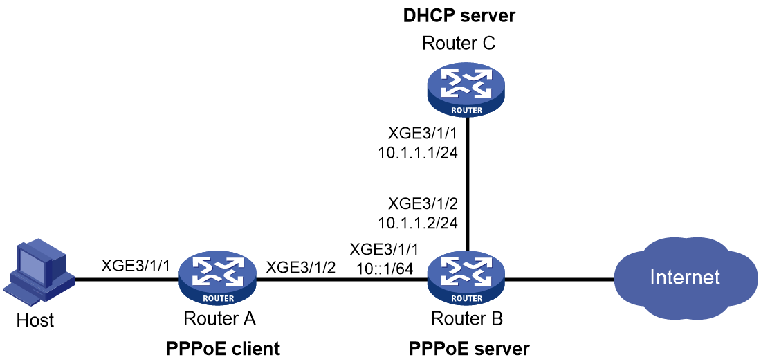
Procedure
1. Configure Router C (DHCP server):
# Enable DHCP.
<RouterC> system-view
[RouterC] dhcp enable
# Configure IP pool pool1 to assign IP addresses and other configuration parameters to clients on subnet 2.2.2.0/24.
[RouterC] ip pool pool1
[RouterC-ip-pool-pool1] network 1.1.1.0 24
[RouterC-ip-pool-pool1] gateway-list 1.1.1.1
[RouterC-ip-pool-pool1] dns-list 8.8.8.8
# Exclude the gateway address from dynamic allocation.
[RouterC-ip-pool-pool1] forbidden-ip 1.1.1.1
[RouterC-ip-pool-pool1] quit
# Configure the default route to the PPPoE server.
[RouterC] ip route-static 0.0.0.0 0 10.1.1.2
2. Configure Router B (PPPoE server):
# Create Virtual-Template 1.
<RouterB> system-view
[RouterB] interface virtual-template 1
# Configure Virtual-Template 1 to use CHAP to authenticate the peer.
[RouterB-Virtual-Template1] ppp authentication-mode chap domain dm1
# Enable Virtual-Template 1 to advertise RA messages.
[RouterB-Virtual-Template1] undo ipv6 nd ra halt
[RouterB-Virtual-Template1] quit
# Enable DHCP.
[RouterB] dhcp enable
# Create a remote BAS IP pool named pool1, and specify the gateway IP address and the network mask for the IP pool. Exclude IP address 1.1.1.1 from dynamic allocation, and specify a DHCP server for the IP pool.
[RouterB] ip pool pool1 bas remote
[RouterB-ip-pool-pool1] gateway 1.1.1.1 24
[RouterB-ip-pool-pool1] forbidden-ip 1.1.1.1
[RouterB-ip-pool-pool1] remote-server 10.1.1.1
[RouterB-ip-pool-pool1] quit
# Configure Ten-GigabitEthernet 3/1/1 to automatically generate an IPv6 link-local address.
[RouterB] interface ten-gigabitethernet 3/1/1
[RouterB-Ten-GigabitEthernet3/1/1] ipv6 address auto link-local
# Enable Ten-GigabitEthernet 3/1/1 to advertise RA messages.
[RouterB-Ten-GigabitEthernet3/1/1] undo ipv6 nd ra halt
# Enable the DHCP relay agent on Ten-GigabitEthernet 3/1/1.
[RouterB-Ten-GigabitEthernet3/1/1] dhcp select relay
# Enable the DHCPv6 server on Ten-GigabitEthernet 3/1/1.
[RouterB-Ten-GigabitEthernet3/1/1] ipv6 dhcp select server
# Enable the PPPoE sever on Ten-GigabitEthernet 3/1/1, and bind the interface to Virtual-Template 1.
[RouterB-Ten-GigabitEthernet3/1/1] pppoe-server bind virtual-template 1
[RouterB-Ten-GigabitEthernet3/1/1] quit
# (For NDRA) Create DHCPv6 prefix pool 1, and specify the prefix 10::/32 with the assigned prefix length 64. Prefix pool 1 contains 4294967296 prefixes from 10::/64 to 10:0:FFFF:FFFF::/64.
[RouterB] ipv6 dhcp prefix-pool 1 prefix 10::/32 assign-len 64
# Create an IPv6 address pool named ndra and apply prefix pool 1 to the IPv6 address pool.
[RouterB] ipv6 pool ndra
[RouterB-ipv6-pool-ndra] prefix-pool 1 export-route
[RouterB-ipv6-pool-ndra] quit
# (For IA_PD) Create prefix pool 6, and specify prefix 20::/32 with assigned prefix length 42.
[RouterB] ipv6 dhcp prefix-pool 6 prefix 20::/32 assign-len 42
# Create IPv6 address pool iapd, and apply prefix pool 6 to address pool iapd.
[RouterB] ipv6 pool iapd
[RouterB-ipv6-pool-iapd] prefix-pool 6 export-route
[RouterB-ipv6-pool-iapd] quit
# Configure a PPPoE user.
[RouterB] local-user user1 class network
[RouterB-luser-network-user1] password simple 123456TESTplat&!
[RouterB-luser-network-user1] service-type ppp
[RouterB-luser-network-user1] quit
# In the ISP domain dm1, perform local AAA for PPP users, and authorize an IPv4 address pool, ND prefix pool, IPv6 DNS address, and IPv6 address pool to PPP users.
[RouterB] domain name dm1
[RouterB-isp-dm1] authentication ppp local
[RouterB-isp-dm1] accounting ppp local
[RouterB-isp-dm1] authorization ppp local
[RouterB-isp-dm1] authorization-attribute ip-pool pool1
[RouterB-isp-dm1] authorization-attribute ipv6-nd-prefix-pool ndra
[RouterB-isp-dm1] authorization-attribute primary-dns ipv6 8::8
[RouterB-isp-dm1] authorization-attribute ipv6-pool iapd
[RouterB-isp-dm1] quit
3. Configure Router A (PPPoE client):
|
|
IMPORTANT: · The device (Router B in this example) can only act as a PPPoE server, and cannot act as a PPPoE client. · The configuration for the device acting as the PPPoE client varies by version. The configuration in this section is for reference only. For more information, see the manual for the device acting as the PPPoE client. |
# Enable bundle DDR on interface Dialer 1.
<RouterA> system-view
[RouterA] interface dialer 1
[RouterA-Dialer1] dialer bundle enable
# On Dialer 1, configure the CHAP username and password sent from Router A to Router B as user1 and 123456TESTplat&! when Router A is authenticated by Router B by using CHAP.
[RouterA-Dialer1] ppp chap user user1
[RouterA-Dialer1] ppp chap password simple 123456TESTplat&!
# Configure the PPPoE session to operate in permanent mode.
[RouterA-Dialer1] dialer timer idle 0
# Set the DDR auto-dial interval to 60 seconds.
[RouterA-Dialer1] dialer timer autodial 60
# (For IPv4) Configure Dialer 1 to obtain an IP address through PPP negotiation, enable Dialer 1 to actively request the DNS server IP address from its peer, and configure Dialer 1 to accept the DNS server IP addresses assigned by the peer even though it does not request DNS server IP addresses from the peer.
[RouterA-Dialer1] ip address ppp-negotiate
[RouterA-Dialer1] ppp ipcp dns request
[RouterA-Dialer1] ppp ipcp dns admit-any
# (For IPv4) Translate the source addresses of the packets from internal hosts into the IP address of Dialer 1.
[RouterA-Dialer1] nat outbound
# (For NDRA) Configure Dialer 1 to automatically generate an IPv6 global unicast address.
[RouterA-Dialer1] ipv6 address auto
# (For IA_PD) Configure Dialer 1 to use DHCPv6 to obtain an IPv6 address and other configuration parameters.
[RouterA-Dialer1] ipv6 address dhcp-alloc
# (For IA_PD) Configure Dialer 1 as a DHCPv6 client for IPv6 prefix acquisition. Configure the DHCPv6 client to assign ID 1 to the obtained IPv6 prefix.
[RouterA-Dialer1] ipv6 dhcp client pd 1
[RouterA-Dialer1] quit
# Configure a PPPoE session corresponding to Dialer bundle 1, which corresponds to Dialer 1.
[RouterA] interface ten-gigabitethernet 3/1/2
[RouterA-Ten-GigabitEthernet3/1/2] pppoe-client dial-bundle-number 1
[RouterA-Ten-GigabitEthernet3/1/2] quit
# Configure default routes.
[RouterA] ip route-static 0.0.0.0 0 dialer 1
[RouterA] ipv6 route-static :: 0 dialer 1
# Enable DHCP.
[RouterA] dhcp enable
# Configure IP address pool pool1 to assign IPv4 addresses and other configuration parameters to clients on subnet 192.168.1.0/24.
[RouterA] ip pool pool1
[RouterA-ip-pool-pool1] network 192.168.1.0 24
[RouterA-ip-pool-pool1] gateway-list 192.168.1.1
[RouterA-ip-pool-pool1] dns-list 8.8.8.8
# Exclude the gateway address from dynamic allocation.
[RouterA-ip-pool-pool1] forbidden-ip 192.168.1.1
[RouterA-ip-pool-pool1] quit
# Assign IP address 192.168.1.1 to Ten-GigabitEthernet3/1/1.
[RouterA] interface ten-gigabitethernet 3/1/1
[RouterA-Ten-GigabitEthernet3/1/1] ip address 192.168.1.1 24
# Enable Ten-GigabitEthernet3/1/1 to advertise RA messages.
[RouterA-Ten-GigabitEthernet3/1/1] undo ipv6 nd ra halt
# Configure Ten-GigabitEthernet3/1/1 to dynamically obtain IPv6 prefix 1 (use IPv6 prefix 1 to generate IPv6 address 20::123:1:1, which must be configured as the gateway address for users attached to Router A) and advertise IPv6 prefix 1 to endpoints through RA messages.
[RouterA-Ten-GigabitEthernet3/1/1] ipv6 address 1 123::123:1:1/64
[RouterA-Ten-GigabitEthernet3/1/1] quit
Verifying the configuration
# Verify that Router B has assigned a prefix to Router A through DHCPv6. After Router A is configured and accesses Router B through username user1 and password 123456TESTplat&! through PPPoE, Router B automatically obtains an IPv4 address through DHCPv4 and generates an IPv6 global unicast address through the authorized IPv6 prefix and IPv6 interface identifier obtained through IPv6CP negotiation.
[RouterB] display access-user interface ten-gigabitethernet 3/1/1
UserID Interface IP address MAC address S-/C-VLAN
Username Access type
IPv6 address
0x6 XGE3/1/1 1.1.1.2 001b-21a8-0949 -/-
user1 PPPoE
10::F85B:7EE1:1410:74C9
# Verify that Router B has assigned a prefix to Router A through DHCPv6.
[RouterB] display ipv6 dhcp server pd-in-use
Pool: iapd
IPv6 prefix Type Lease expiration
20::/42 Auto(C) Jul 10 19:45:01 2019
Pool: ndra
IPv6 prefix Type Lease expiration
10::/64 Auto(C) Expires after 2100
# Display information about prefixes on Router A.
[RouterA] display ipv6 prefix
Number Prefix Type
1 20::/42 Dynamic
The output shows that Router A has created prefix 1 based on the ipv6 dhcp client pd 1 command after obtaining a prefix from Router B.
Then, Router A can assign the prefix 20::/42 to the host who uses the prefix to generate an IPv6 global unicast address.
Example: Configuring the PPPoE server to assign IPv6 addresses through the IA_NA+IA_PD method
Network configuration
As shown in Figure 14, configure the PPPoE server as follows:
· Configure the PPPoE server to assign an IPv6 global unicast address to the WAN interface (Dialer 1 in this example) of Router A.
· Configure the PPPoE server to assign a prefix to Router A through IA_PD. Router A then assigns the prefix to the host for it to generate an IPv6 address.

Procedure
1. Configure Router B (PPPoE server):
# Create Virtual-Template 1.
<RouterB> system-view
[RouterB] interface virtual-template 1
# Configure Virtual-Template 1 to use CHAP to authenticate the peer.
[RouterB-Virtual-Template1] ppp authentication-mode chap domain dm1
# Enable Virtual-Template 1 to advertise RA messages.
[RouterB-Virtual-Template1] undo ipv6 nd ra halt
# Set the managed address configuration flag (M) to 1 in RA advertisements to be sent.
[RouterB-Virtual-Template1] ipv6 nd autoconfig managed-address-flag
# Set the other stateful configuration flag (O) to 1 in RA advertisements to be sent on Virtual-Template 1.
[RouterB-Virtual-Template1] ipv6 nd autoconfig other-flag
[RouterB-Virtual-Template1] quit
# Configure Ten-GigabitEthernet 3/1/1 to automatically generate an IPv6 link-local address.
[Router] interface ten-gigabitethernet 3/1/1
[RouterB-Ten-GigabitEthernet3/1/1] ipv6 address auto link-local
# Enable Ten-GigabitEthernet 3/1/1 to advertise RA messages.
[RouterB-Ten-GigabitEthernet3/1/1] undo ipv6 nd ra halt
# Enable the DHCPv6 server on Ten-GigabitEthernet 3/1/1.
[RouterB-Ten-GigabitEthernet3/1/1] ipv6 dhcp select server
# Enable the PPPoE sever on Ten-GigabitEthernet 3/1/1, and bind the interface to Virtual-Template 1.
[RouterB-Ten-GigabitEthernet3/1/1] pppoe-server bind virtual-template 1
[RouterB-Ten-GigabitEthernet3/1/1] quit
# (For IA_PD) Create prefix pool 6, and specify prefix 20::/32 with assigned prefix length 42.
[RouterB] ipv6 dhcp prefix-pool 6 prefix 20::/32 assign-len 42
# Create an IPv6 address pool named pool1.
[RouterB] ipv6 pool pool1
# (For IA_NA) Configure IPv6 address pool pool1 with network 1::/32 for dynamic allocation and DNS server IP address 8::8.
[RouterB-ipv6-pool-pool1] network 1::/32
[RouterB-ipv6-pool-pool1] dns-server 8::8
# (For IA_PD) Apply prefix pool 6 to address pool pool1.
[RouterB-ipv6-pool-pool1] prefix-pool 6 export-route
[RouterB-ipv6-pool-pool1] quit
# Configure a PPPoE user.
[RouterB] local-user user1 class network
[RouterB-luser-network-user1] password simple 123456TESTplat&!
[RouterB-luser-network-user1] service-type ppp
[RouterB-luser-network-user1] quit
# In the ISP domain dm1, perform local AAA for PPP users, and authorize an address pool to PPP users.
[RouterB] domain name dm1
[RouterB-isp-dm1] authentication ppp local
[RouterB-isp-dm1] accounting ppp local
[RouterB-isp-dm1] authorization ppp local
[RouterB-isp-dm1] authorization-attribute ipv6-pool pool1
[RouterB-isp-dm1] quit
2. Configure Router A (PPPoE client):
|
|
IMPORTANT: · The device (Router B in this example) can only act as a PPPoE server, and cannot act as a PPPoE client. · The configuration for the device acting as the PPPoE client varies by version. The configuration in this section is for reference only. For more information, see the manual for the device acting as the PPPoE client. |
# Enable bundle DDR on interface Dialer 1.
<RouterA> system-view
[RouterA] interface dialer 1
[RouterA-Dialer1] dialer bundle enable
# On Dialer 1, configure the CHAP username and password sent from Router A to Router B as user1 and 123456TESTplat&! when Router A is authenticated by Router B by using CHAP.
[RouterA-Dialer1] ppp chap user user1
[RouterA-Dialer1] ppp chap password simple 123456TESTplat&!
# Configure the PPPoE session to operate in permanent mode.
[RouterA-Dialer1] dialer timer idle 0
# Set the DDR auto-dial interval to 60 seconds.
[RouterA-Dialer1] dialer timer autodial 60
# (For IA_NA+IA_PD) Configure Dialer 1 to use DHCPv6 to obtain an IPv6 address and other configuration parameters.
[RouterA-Dialer1] ipv6 address dhcp-alloc
# (For IA_PD) Configure Dialer 1 as a DHCPv6 client for IPv6 prefix acquisition. Configure the DHCPv6 client to assign ID 1 to the obtained IPv6 prefix.
[RouterA-Dialer1] ipv6 dhcp client pd 1
[RouterA-Dialer1] quit
# Configure a PPPoE session corresponding to Dialer bundle 1, which corresponds to Dialer 1.
[RouterA] interface ten-gigabitethernet 3/1/2
[RouterA-Ten-GigabitEthernet3/1/2] pppoe-client dial-bundle-number 1
[RouterA-Ten-GigabitEthernet3/1/2] quit
# Configure a default route.
[RouterA] ipv6 route-static :: 0 dialer 1
# Enable Ten-GigabitEthernet3/1/1 to advertise RA messages.
[RouterA] interface ten-gigabitethernet 3/1/1
[RouterA-Ten-GigabitEthernet3/1/1] undo ipv6 nd ra halt
# Configure Ten-GigabitEthernet3/1/1 to dynamically obtain IPv6 prefix 1 (use IPv6 prefix 1 to generate IPv6 address 20::123:1:1, which must be configured as the gateway address for users attached to Router A) and advertise IPv6 prefix 1 to endpoints through RA messages.
[RouterA-Ten-GigabitEthernet3/1/1] ipv6 address 1 123::123:1:1/64
[RouterA-Ten-GigabitEthernet3/1/1] quit
Verifying the configuration
# Verify that Router B has assigned an IPv6 global unicast address to Router A through DHCPv6 after Router A is configured and accesses Router B through username user1 and password 123456TESTplat&! through PPPoE.
[Router] display access-user interface ten-gigabitethernet 3/1/1
UserID Interface IP address MAC address S-/C-VLAN
Username Access type
IPv6 address
0x9 XGE3/1/1 - 001b-21a8-0949 -/-
user1 PPPoE
1::1
# Verify that Router B has assigned a prefix to Router A through DHCPv6.
[RouterB] display ipv6 dhcp server pd-in-use
Pool: pool1
IPv6 prefix Type Lease expiration
20::/42 Auto(C) Jul 10 19:45:01 2019
# Display information about prefixes on Router A.
[RouterA] display ipv6 prefix
Number Prefix Type
1 20::/42 Dynamic
The output shows that Router A has created prefix 1 based on the ipv6 dhcp client pd 1 command after obtaining a prefix from Router B.
Then, Router A can assign the prefix 20::/42 to the host who uses the prefix to generate an IPv6 global unicast address.
Example: Assigning IP addresses to dual-stack users through the local DHCP server
Network configuration
As shown in Figure 15, configure the PPPoE server as a DHCP server to assign an IPv4 address to the host and configure it as a DHCPv6 server to assign an IPv6 address to the host.

Procedure
# Configure Virtual-Template 1 to use CHAP for authentication.
<Router> system-view
[Router] interface virtual-template 1
[Router-Virtual-Template1] ppp authentication-mode chap domain dm1
# Enable Virtual-Template 1 to advertise RA messages.
[Router-Virtual-Template1] undo ipv6 nd ra halt
# Set the managed address configuration flag (M) to 1 in RA advertisements to be sent.
[Router-Virtual-Template1] ipv6 nd autoconfig managed-address-flag
# Set the other stateful configuration flag (O) to 1 in RA advertisements to be sent on Virtual-Template 1.
[Router-Virtual-Template1] ipv6 nd autoconfig other-flag
[Router-Virtual-Template1] quit
# Configure Ten-GigabitEthernet 3/1/1 to automatically generate an IPv6 link-local address.
[Router] interface ten-gigabitethernet 3/1/1
[Router-Ten-GigabitEthernet3/1/1] ipv6 address auto link-local
# Enable Ten-GigabitEthernet 3/1/1 to advertise RA messages.
[Router-Ten-GigabitEthernet3/1/1] undo ipv6 nd ra halt
# Enable the DHCPv6 server on Ten-GigabitEthernet 3/1/1.
[Router-Ten-GigabitEthernet3/1/1] ipv6 dhcp select server
# Enable the PPPoE server on Ten-GigabitEthernet 3/1/1, and bind the interface to Virtual-Template 1.
[Router-Ten-GigabitEthernet3/1/1] pppoe-server bind virtual-template 1
[Router-Ten-GigabitEthernet3/1/1] quit
# Enable DHCPv4.
[Router] dhcp enable
# Configure local BAS IP address pool pool1.
[Router] ip pool pool1 bas local
[Router-ip-pool-pool1] gateway 1.1.1.1 24
[Router-ip-pool-pool1] dns-list 8.8.8.8
# Exclude the IP address 1.1.1.1 from dynamic allocation in IP address pool pool1.
[Router-ip-pool-pool1] forbidden-ip 1.1.1.1
[Router-ip-pool-pool1] quit
# Configure IPv6 address pool pool1 with network 1::/32 for dynamic allocation and DNS server IP address 8::8.
[Router] ipv6 pool pool1
[Router-ipv6-pool-pool1] network 1::/32 export-route
[Router-ipv6-pool-pool1] dns-server 8::8
[Router-ipv6-pool-pool1] quit
# Create a PPPoE user.
[Router] local-user user1 class network
[Router-luser-network-user1] password simple 123456TESTplat&!
[Router-luser-network-user1] service-type ppp
[Router-luser-network-user1] quit
# In the ISP domain dm1, perform local AAA for PPP users, and authorize address pools to PPP users.
[Router] domain name dm1
[Router-isp-dm1] authentication ppp local
[Router-isp-dm1] accounting ppp local
[Router-isp-dm1] authorization ppp local
[Router-isp-dm1] authorization-attribute ipv6-pool pool1
[Router-isp-dm1] authorization-attribute ipv6-pool pool1
[Router-isp-dm1] quit
Verifying the configuration
# Log in to the router by using username user1 and password 123456TESTplat&!.
# Display information about IP addresses assigned by the DHCP server.
[Router] display access-user interface Ten-GigabitEthernet 3/1/1
UserID Interface IP address MAC address S-/C-VLAN
Username Access type
IPv6 address
0xc XGE3/1/1 1.1.1.2 001b-21a8-0949 -/-
user1 PPPoE
1::1
The output shows that the router has assigned an IPv4 address and an IPv6 address to the host.
Example: Configuring PPPoE server RADIUS-based IP address assignment
Network configuration
As shown in Figure 16, configure the PPPoE server to meet the following requirements:
· The PPPoE server uses the RADIUS server to perform authentication, authorization, and accounting for access users. This example uses Free RADIUS that runs in the Linux operating system.
· The RADIUS server assigns access users an IP address pool named pool1 and a VPN instance named vpn1.
· Users in vpn1 obtain IP addresses from IP address pool pool1.
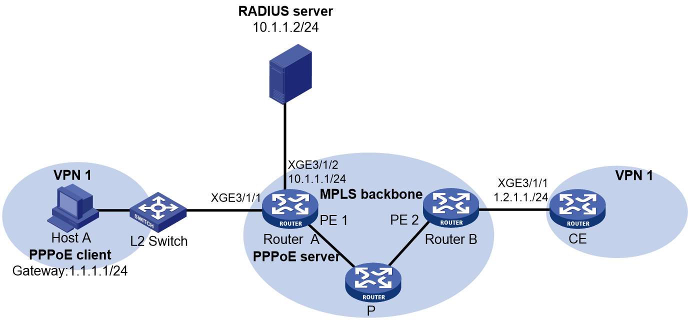
Prerequisites
For the two ends of VPN 1 to communicate with each other, specify the same route target attributes on the two PEs (Router A and Router B). This example describes only the authentication-related configuration on the PE that is connected to the PPPoE client. For information about configuring MPLS L3VPN, see MPLS Configuration Guide.
Procedure
1. Configure the RADIUS server:
# Add the following text to the client.conf file to configure RADIUS client information.
client 10.1.1.1/24 {
secret = radius
}
Where, secret represents the shared key for authentication, authorization, and accounting.
# Add the following text to the users.conf file to configure legal user information.
user1 Auth-Type == CHAP,User-Password := pass1
Service-Type = Framed-User,
Framed-Protocol = PPP,
Framed-Pool = "pool1",
H3C-VPN-Instance = "vpn1",
2. Configure Router A:
a. Configure the PPPoE server:
# Configure Virtual-Template 1 to use CHAP for authentication and use ISP domain dm1 as the authentication domain.
<RouterA> system-view
[RouterA] interface virtual-template 1
[RouterA-Virtual-Template1] ppp authentication-mode chap domain dm1
[RouterA-Virtual-Template1] quit
# Enable DHCP.
[RouterA] dhcp enable
# Configure local BAS IP address pool pool1.
[RouterA] ip pool pool1 bas local
[RouterA-ip-pool-pool1] vpn-instance vpn1
[RouterA-ip-pool-pool1] gateway 1.1.1.1 24
[RouterA-ip-pool-pool1] dns-list 8.8.8.8
# Exclude IP address 1.1.1.1 from dynamic allocation in the address pool.
[RouterA-ip-pool-pool1] forbidden-ip 1.1.1.1
[RouterA-ip-pool-pool1] quit
# Enable the PPPoE server on Ten-GigabitEthernet 3/1/1, and bind the interface to Virtual-Template 1.
[RouterA] interface ten-gigabitethernet 3/1/1
[RouterA-Ten-GigabitEthernet3/1/1] pppoe-server bind virtual-template 1
[RouterA-Ten-GigabitEthernet3/1/1] quit
b. Configure a RADIUS scheme:
# Create a RADIUS scheme named rs1, and enter its view.
[RouterA] radius scheme rs1
# Specify the primary authentication server and the primary accounting server.
[RouterA-radius-rs1] primary authentication 10.1.1.2
[RouterA-radius-rs1] primary accounting 10.1.1.2
# Set the shared key for secure communication with the server to radius in plain text.
[RouterA-radius-rs1] key authentication simple radius
[RouterA-radius-rs1] key accounting simple radius
# Exclude domain names in the usernames sent to the RADIUS server.
[RouterA-radius-rs1] user-name-format without-domain
[RouterA-radius-rs1] quit
c. Configure an authentication domain:
# Create an ISP domain named dm1.
[RouterA] domain name dm1
# In ISP domain dm1, perform RADIUS authentication, authorization, and accounting for users based on scheme rs1.
[RouterA-isp-dm1] authentication ppp radius-scheme rs1
[RouterA-isp-dm1] authorization ppp radius-scheme rs1
[RouterA-isp-dm1] accounting ppp radius-scheme rs1
[RouterA-isp-dm1] quit
Verifying the configuration
# Verify that Host A can successfully ping CE. (Details not shown.)
# Display binding information about assigned IP addresses in VPN1.
[RouterA] display dhcp server ip-in-use vpn-instance vpn1
IP address Client identifier/ Lease expiration Type
Hardware address
1.1.1.2 3030-3030-2e30-3030- Unlimited Auto(C)
662e-3030-3033-2d45-
7468-6572-6e65-74
Example: Configuring PPPoE agency (authorizing a remote BAS IP address pool)
Network configuration
Campus users act as DHCP clients and access the campus BRAS in IPoE mode through a Layer 2 network. The campus BRAS is connected to the ISP BRAS to perform PPPoE agency for external network traffic of campus users. When a campus user accesses the external network, the campus BRAS simulates a PPPoE client to initiate dialup requests for network access to the ISP BRAS acting as the PPPoE server.
· For the internal network traffic:
¡ Enable IPoE on Ten-GigabitEthernet 3/1/2 on the campus BRAS to provide the BRAS access service for campus users.
¡ A DHCP server allocates IPv4 addresses to campus users.
¡ A server acts as both the AAA server and Web server.
¡ After a DHCP client is abnormally logged out, the user can come online again through IPv4 packet initiation.
· For the external network traffic:
Enable PPPoE agency on Ten-GigabitEthernet 3/1/3 of the campus BRAS. When a campus user needs to access the external network, the campus BRAS provides the agency service for the user. After the agency is performed successfully for the user, the user can access the specified ISP network.
Figure 17 Network diagram
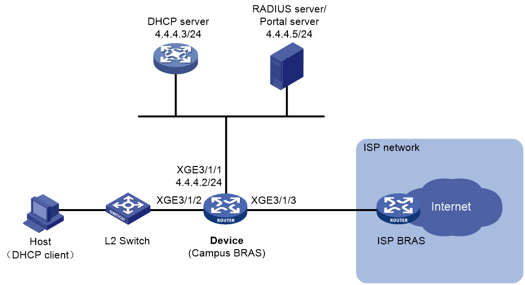
Prerequisites
Configure IP addresses for interfaces, and make sure devices can reach each other at Layer 3.
Configure the AAA server and Web server correctly. (Details not shown.)
Restrictions and guidelines
For a campus user, you must open an ISP account, and bind the internal network account of the campus user to the opened ISP account and PPPoE agency group name of the ISP. Then, a campus user can trigger the agency process and pass the PPPoE authentication of the ISP after coming online.
Procedure
1. Configure the DHCP server:
# Enable DHCP globally.
<DHCP-server> system-view
[DHCP-server] dhcp enable
# Create address pool pool1 and enter its view.
[DHCP-server] ip pool pool1
# Specify primary subnet 3.3.3.0/24 for dynamic allocation in the address pool.
[DHCP-server-ip-pool-pool1] network 3.3.3.0 24
# Specify gateway address 3.3.3.1.
[DHCP-server-ip-pool-pool1] gateway-list 3.3.3.1
# Exclude IP address 3.3.3.1 from dynamic allocation.
[DHCP-server-ip-pool-pool1] forbidden-ip 3.3.3.1
[DHCP-server-ip-pool-pool1] quit
# Configure the default route.
[DHCP-server] ip route-static 0.0.0.0 0 4.4.4.2
2. Configure Device:
a. Configure the DHCP relay agent:
# Enable DHCP globally.
<Device> system-view
[Device] dhcp enable
# Create remote BAS IP address pool pool1, and specify the gateway address, excluded IP address, and DHCP server for the address pool.
[Device] ip pool pool1 bas remote
[Device-ip-pool-pool1] gateway 3.3.3.1 24
[Device-ip-pool-pool1] forbidden-ip 3.3.3.1
[Device-ip-pool-pool1] remote-server 4.4.4.3
[Device-ip-pool-pool1] quit
b. Configure a RADIUS scheme:
# Create RADIUS scheme rs1, and enter its view.
[Device] radius scheme rs1
# Configure primary servers and keys for authentication and accounting.
[Device-radius-rs1] primary authentication 4.4.4.5
[Device-radius-rs1] primary accounting 4.4.4.5
[Device-radius-rs1] key authentication simple radius
[Device-radius-rs1] key accounting simple radius
# Send the username to the RADIUS server as the username is entered.
[Device-radius-rs1] user-name-format keep-original
[Device-radius-rs1] quit
c. Configure authentication domains:
# (IPoE preauthentication domain.) Configure authentication domain dm1 as the preauthentication domain for IPoE users.
[Device] domain name dm1
[Device-isp-dm1] authentication ipoe none
[Device-isp-dm1] authorization ipoe none
[Device-isp-dm1] accounting ipoe none
# Configure the authorized address pool and user group in the preauthentication domain.
[Device-isp-dm1] authorization-attribute user-group pre
[Device-isp-dm1] authorization-attribute ip-pool pool1
# Configure the Web authentication page URL and the Web authentication server IP address.
[Device-isp-dm1] web-server url http://4.4.4.5:8080/portal/
[Device-isp-dm1] web-server ip 4.4.4.5
[Device-isp-dm1] quit
# (IPoE postauthentication domain.) Configure authentication domain dm2 as the postauthentication domain for IPoE users.
[Device] domain name dm2
[Device-isp-dm2] authentication ipoe radius-scheme rs1
[Device-isp-dm2] authorization ipoe radius-scheme rs1
[Device-isp-dm2] accounting ipoe radius-scheme rs1
# Configure the authorized PPPoE agency user group in the postauthentication domain.
[Device-isp-dm2] authorization-attribute user-group pppoea
[Device-isp-dm2] quit
# (Authentication domain for PPPoE agency users.) Create ISP domain dm3, and enter its view.
[Device] domain name dm3
# Configure the PPPoE agency users to use RADIUS scheme rs1 for accounting. For PPPoE agency users in the domain, you can configure only the accounting method and cannot configure the authentication or authorization method in the current software version. The system uses the default authentication method (no authentication) and the default authorization method (no authorization) for PPPoE agency users in the domain.
[Device-isp-dm3] accounting pppoea radius-scheme rs1
[Device-isp-dm3] quit
d. Configure IPoE Web authentication.
For more information about configuring IPoE Web authentication, see “Configuring IPoE.”
e. Configure the PPPoE agency:
# Configure advanced IPv4 ACL neiwang_permit with the following rules:
- Configure a rule to match traffic destined to 4.4.4.6. In this example, traffic destined to 4.4.4.6 is internal network traffic. You can modify the destination IP address as needed.
- Configure a rule to match traffic destined to user network segment 3.3.3.0/24, so that users on the same network segment can communicate with each other and the gateway. If you do not configure this rule, this type of traffic will be processed as the external network traffic. As a result, users on the same network segment cannot communicate with each other and the gateway.
[Device] acl advanced name neiwang_permit
[Device-acl-ipv4-adv-neiwang_permit] rule 0 permit ip destination 4.4.4.6 0
[Device-acl-ipv4-adv-neiwang_permit] rule 10 permit ip destination 3.3.3.0 0.0.0.255
[Device-acl-ipv4-adv-neiwang_permit] quit
# Create a PPPoE agency user group named pppoea.
[Device] user-group pppoea
New user group added.
# Configure a PPPoE agency forwarding policy. Traffic matching the specified ACL is considered as the internal network traffic and is directly forwarded. Traffic not matching the specified ACL is considered as the external network traffic and forwarded through the PPPoE agency.
[Device-ugroup-pppoea] pppoe-agency forward ipv4 acl name neiwang_permit
# Configure the authentication domain for PPPoE agency users. The BRAS can initiate PPPoE dialup to the corresponding ISP only after a PPPoE agency user passes authentication and comes online in the domain. The username and password used for authentication can only be deployed through COA messages by the AAA server, and an account must be opened for the campus user in an ISP.
[Device-ugroup-pppoea] pppoe-agency authentication domain dm3
[Device-ugroup-pppoea] quit
# Create VT interface 1.
[Device] interface virtual-template 1
[Device-Virtual-Template1] quit
# Enable the PPPoE agency on Ten-GigabitEthernet 3/1/3. Bind the interface to a PPPoE agency group. The PPPoE agency group name is deployed through COA messages by the AAA server. Suppose the PPPoE agency group name deployed through COA messages is cmcc.
[Device] interface ten-gigabitethernet 3/1/3
[Device–Ten-GigabitEthernet3/1/3] pppoe-agency bind virtual-template 1 pppoe-agency-group cmcc
[Device–Ten-GigabitEthernet3/1/3] quit
# Enable the RADIUS DAE service, and enter RADIUS DAE server view.
[Device] radius dynamic-author server
# Specify the RADIUS DAE client IP address as 4.4.4.5 and configure the shared key as 123456 in plain text.
[Device-radius-da-server] client ip 4.4.4.5 key simple 123456
# Configure the listening port of the server for agency reply packets as 3799 during the PPPoE agency process. (The default port number is 3799 in this example.)
[Device-radius-da-server] pppoe-agency reply-port 3799
[Device-radius-da-server] quit
Verifying the configuration
# After a user passes preauthentication, use the following command to view online IPoE user information. The output shows that the user obtains IP address 3.3. 3.2.
[Device] display access-user interface ten-gigabitethernet 3/1/2
UserID Interface IP address MAC address S-/C-VLAN
Username Access type
IPv6 address
0x5c XGE3/1/2 3.3.3.2 000c-29a6-b656 -/-
000c29a6b656 L2 IPoE dynamic
-
# After a user passes preauthentication, enter the username and password on the Web page to complete Web authentication. After the user passes Web authentication, execute the following command to view the online information of the IPoE user.
[Device] display access-user interface ten-gigabitethernet 3/1/2
UserID Interface IP address MAC address S-/C-VLAN
Username Access type
IPv6 address
0x5c XGE3/1/2 3.3.3.2 000c-29a6-b656 -/-
user1@dm2 Web auth
-
# The AAA server uses a COA message to issue a PPPoE agency request. In the request, the agency group name is cmcc, and the username and password are the account information registered in the ISP. After the user comes online through the PPPoE agency successfully, verify that the user information is as follows.
[Device] display access-user interface ten-gigabitethernet 3/1/3
UserID Interface IP address MAC address S-/C-VLAN
Username Access type
IPv6 address
0x5d XGE3/1/3 6.0.0.2 000c-29a6-b656 -/-
test PPPoEA
-
Example: Configuring PPPoE static dual-stack users
Network configuration
Host is manually configured with static IPv4 address 1.1.1.2/24, static IPv6 address 1::021B:21FF:FEA8:0949/64, and static IPv6 DNS server address 8::F85B:7EE1:1410:74C9. Host is connected to Router through an Ethernet interface, and Router acts as the PPPoE server. Configure Host to access Router through PPPoE by using the manually configured static IP addresses.
Figure 18 Network diagram

Restrictions and guidelines
In some operating systems (for example, Windows 7), if the interface ID in the IPv6 global unicast address requested by a DHCPv6 client is different from the interface ID in the link-local address of the DHCPv6 client, Windows 7 will consider the IPv6 global unicast address as unavailable. As a result, the DHCPv6 client cannot use the address as the source address to send packets. Therefore, as a best practice to ensure that the function operates normally, configure the interface ID in a static IPv6 address to be the same as that in the link-local address when configuring the static IPv6 address. For example, the link-local address in this example is FE80::021B:21FF:FEA8:0949, and the static IPv6 address is 1::021B:21FF:FEA8:0949.
Procedure
# Configure Virtual-Template 1 to use CHAP for authenticating the peer.
<Router> system-view
[Router] interface virtual-template 1
[Router-Virtual-Template1] ppp authentication-mode chap domain dm1
# Configure the device to allow a remote user to come online by using a self-configured static IPv4 address and IPv6 address.
[Router-Virtual-Template1] ppp accept remote-ip-address
[Router-Virtual-Template1] ppp accept remote-ipv6-address
# Enable Virtual-Template 1 to advertise RA messages. Set the managed address configuration flag (M) to 1 to prevent the IPv6 static users from coming online through NDRA.
[Router-Virtual-Template1] undo ipv6 nd ra halt
[Router-Virtual-Template1] ipv6 nd autoconfig managed-address-flag
[Router-Virtual-Template1] quit
# Automatically generate a link-local address for Ten-GigabitEthernet 3/1/1.
[Router] interface ten-gigabitethernet 3/1/1
[Router-Ten-GigabitEthernet3/1/1] ipv6 address auto link-local
# Enable Virtual-Template 1 to advertise RA messages.
[Router-Ten-GigabitEthernet3/1/1] undo ipv6 nd ra halt
# Disable the DHCPv6 server and DHCPv6 relay agent on the interface to prevent IPv6 static users from coming online through IA_NA. (The default configuration.)
[Router-Ten-GigabitEthernet3/1/1] undo ipv6 dhcp select
# Enable the PPPoE server on Ten-GigabitEthernet 3/1/1 and bind it to Virtual-Template 1.
[Router-Ten-GigabitEthernet3/1/1] pppoe-server bind virtual-template 1
[Router-Ten-GigabitEthernet3/1/1] quit
# Enable DHCPv4.
[Router] dhcp enable
# Configure a local BAS IP address pool pool1.
[Router] ip pool pool1 bas local
[Router-ip-pool-pool1] gateway 1.1.1.1 24
[Router-ip-pool-pool1] dns-list 8.8.8.8
# Exclude gateway IP address 1.1.1.1 and static user IP address 1.1.1.2 from dynamic allocation.
[Router-ip-pool-pool1] forbidden-ip 1.1.1.1
[Router-ip-pool-pool1] forbidden-ip 1.1.1.2
[Router-ip-pool-pool1] quit
# Exclude static user IPv6 address 1::021B:21FF:FEA8:0949 from dynamic allocation.
[Router] ipv6 dhcp server forbidden-address 1::021B:21FF:FEA8:0949
# Configure a PPPoE user.
[Router] local-user user1 class network
[Router-luser-network-user1] password simple 123456TESTplat&!
[Router-luser-network-user1] service-type ppp
[Router-luser-network-user1] quit
# In ISP domain dm1, perform local AAA for users and authorize an address pool.
[Router] domain name dm1
[Router-isp-dm1] authentication ppp local
[Router-isp-dm1] accounting ppp local
[Router-isp-dm1] authorization ppp local
[Router-isp-dm1] authorization-attribute ip-pool pool1
[Router-isp-dm1] quit
Verifying the configuration
After the configuration is completed, Host accesses Router through PPPoE by using username user1 and password 123456TESTplat&!. Verify that Host has come online successfully by using the manually configured static IP addresses.
[Router] display access-user interface ten-gigabitethernet 3/1/1
UserID Interface IP address MAC address S-/C-VLAN
Username Access type
IPv6 address
0xc XGE3/1/1 1.1.1.2 001b-21a8-0949 -/-
user1 PPPoE
1::021B:21FF:FEA8:0949
PPPoE configuration examples(on CUPS network)
In a CUPS network, the CP and UP together act as a BRAS to provide BRAS services.
In a CUPS network, the device can act only as a CP, and cannot act as a UP.
The configuration procedures on UPs in this section are for reference only. For more information, see manuals for devices acting as UPs.
Example: Configuring the PPPoE server to allocate IPv4 addresses through a local DHCP server
Network configuration
As shown in Figure 19, the host runs PPPoE client software.
The CP allocates an IPv4 address to the host through the DHCPv4 protocol.
Configure the BRAS to support the PPPoE server in CUPS mode.
· The UP performs packet forwarding and traffic control.
· The CP performs user identification, initiating authentication requests, authentication, address allocation and management, and access control.

Prerequisites
Configure IP addresses for interfaces, and make sure the devices can reach each other at Layer 3. (Details not shown.)
Configure a management channel, control channel, and protocol channel between a CP and a UP. (Details not shown.)
Procedure
1. Configure the UP:
# Configure the device to operate in user plane mode.
<UP> system-view
[UP] work-mode user-plane
2. Configure the CP:
a. Configure the DHCP server:
# Configure ODAP IP address pool pool1.
<CP> system-view
[CP] ip pool pool1 odap
[CP-ip-pool-pool1] network 1.0.0.0 8 export-route
[CP-ip-pool-pool1] subnet mask-length 16
[CP-ip-pool-pool1] gateway 1.1.1.1 8
[CP-ip-pool-pool1] forbidden-ip 1.1.1.1
[CP-ip-pool-pool1] dns-list 8.8.8.8
[CP-ip-pool-pool1] quit
b. Create a PPPoE user.
[CP] local-user user1 class network
[CP-luser-network-user1] password simple 123456TESTplat&!
[CP-luser-network-user1] service-type ppp
[CP-luser-network-user1] quit
c. In ISP domain dm1, perform local AAA for users and authorize an address pool.
[CP] domain name dm1
[CP-isp-dm1] authentication ppp local
[CP-isp-dm1] accounting ppp local
[CP-isp-dm1] authorization ppp local
[CP-isp-dm1] authorization-attribute ip-pool pool1
[CP-isp-dm1] quit
d. Configure the PPPoE server.
# Configure Virtual-Template 1 to use CHAP for authenticating the peer.
[CP] interface virtual-template 1
[CP-Virtual-Template1] ppp authentication-mode chap domain dm1
[CP-Virtual-Template1] quit
# Enable the PPPoE server on Remote-XGE 1024/3/1/1, and bind the interface to Virtual-Template 1.
[CP] interface remote-xge 1024/3/1/1
[CP-Remote-XGE1024/3/1/1] pppoe-server bind virtual-template 1
[CP-Remote-XGE1024/3/1/1] quit
Verifying the configuration
# Verify that the following information is true:
· The host can use username user1 and password 123456TESTplat&! to can access the Internet through the routers.
· The IP address of the host is the address that the CP specifies for the host.
# Display the PPPoE access user information on the CP.
[CP] display access-user interface remote-xge 1024/3/1/1
Slot 97:
UserID Interface IP address MAC address S-/C-VLAN
Username Access type
IPv6 address
0x6 R-XGE1024/3/1/1 1.0.0.1 0000-5e08-9d00 -/-
user1 PPPoE
-
Example: Configuring the PPPoE server to allocate IP addresses to dual-stack users through a local DHCP server
Network configuration
As shown in Figure 20, the host runs PPPoE client software.
The CP allocates an IPv4 address to the host through the DHCPv4 protocol and an IPv6 address to the host through the DHCPv6 protocol.
Configure the BRAS to support the PPPoE server in CUPS mode.
· The UP performs packet forwarding and traffic control.
· The CP performs user identification, initiating authentication requests, authentication, address allocation and management, and access control.

Prerequisites
Configure IP addresses for interfaces, and make sure the devices can reach each other at Layer 3. (Details not shown.)
Configure a management channel, control channel, and protocol channel between a CP and a UP. (Details not shown.)
Procedure
1. Configure the UP:
# Configure the device to operate in user plane mode.
<UP> system-view
[UP] work-mode user-plane
2. Configure the CP:
a. Configure the DHCP server:
# Create ODAP IP address pool named pool1.
<CP> system-view
[CP] ip pool pool1 odap
[CP-ip-pool-pool1] network 1.0.0.0 8 export-route
[CP-ip-pool-pool1] subnet mask-length 16
[CP-ip-pool-pool1] gateway 1.1.1.1 8
[CP-ip-pool-pool1] forbidden-ip 1.1.1.1
[CP-ip-pool-pool1] dns-list 8.8.8.8
[CP-ip-pool-pool1] quit
# Create ODAP IPv6 address pool named pool1.
[CP] ipv6 pool pool1 odap
[CP-ipv6-pool-pool1] network 1::/32 export-route
[CP-ipv6-pool-pool1] dynamic address assign-length 64
[CP-ipv6-pool-pool1] forbidden-address 1::1
[CP-ipv6-pool-pool1] dns-server 8::8
[CP-ipv6-pool-pool1] quit
# Enable the DHCPv6 server on Remote-XGE 1024/3/1/1.
[CP] interface remote-xge 1024/3/1/1
[CP–Remote-XGE1024/3/1/1] ipv6 dhcp select server
# Configure Remote-XGE 1024/3/1/1 to automatically generate a link-local address, which is to be used as the gateway address for users.
[CP–Remote-XGE1024/3/1/1] ipv6 address auto link-local
# Enable Remote-XGE 1024/3/1/1 to advertise RA messages.
[CP–Remote-XGE1024/3/1/1] undo ipv6 nd ra halt
[CP–Remote-XGE1024/3/1/1] quit
b. Create a PPPoE user.
[CP] local-user user1 class network
[CP-luser-network-user1] password simple 123456TESTplat&!
[CP-luser-network-user1] service-type ppp
[CP-luser-network-user1] quit
c. In ISP domain dm1, perform local AAA for users and authorize an address pool.
[CP] domain name dm1
[CP-isp-dm1] authentication ppp local
[CP-isp-dm1] accounting ppp local
[CP-isp-dm1] authorization ppp local
[CP-isp-dm1] authorization-attribute ip-pool pool1
[CP-isp-dm1] authorization-attribute ipv6-pool pool1
[CP-isp-dm1] quit
d. Configure the PPPoE server.
# Configure Virtual-Template 1 to use CHAP for authenticating the peer.
[CP] interface virtual-template 1
[CP-Virtual-Template1] ppp authentication-mode chap domain dm1
# Enable Virtual-Template 1 to advertise RA messages.
[CP-Virtual-Template1] undo ipv6 nd ra halt
# Set the managed address configuration flag (M) to 1 in RA advertisements to be sent.
[CP-Virtual-Template1] ipv6 nd autoconfig managed-address-flag
# Set the other stateful configuration flag (O) to 1 in RA advertisements to be sent on Virtual-Template 1.
[CP-Virtual-Template1] ipv6 nd autoconfig other-flag
[CP-Virtual-Template1] quit
# Enable the PPPoE server on Remote-XGE 1024/3/1/1, and bind the interface to Virtual-Template 1.
[CP] interface remote-xge 1024/3/1/1
[CP-Remote-XGE1024/3/1/1] pppoe-server bind virtual-template 1
[CP-Remote-XGE1024/3/1/1] quit
Verifying the configuration
# Verify that the following information is true:
· The host can use username user1 and password 123456TESTplat&! to can access the Internet through the routers.
· The IP address of the host is the address that the CP specifies for the host.
# Display the PPPoE access user information on the CP.
[CP] display access-user interface remote-xge 1024/3/1/1
Slot 97:
UserID Interface IP address MAC address S-/C-VLAN
Username Access type
IPv6 address
0x1 R-XGE1024/3/1/1 1.0.0.1 000c-29a6-b656 -/-
user1 PPPoE
1::2
Example: Configuring the PPPoE server to allocate IP addresses to dual-stack users through a remote DHCP server
Network configuration
As shown in Figure 21, the host acts as the PPPoE client, and runs the PPPoE client dialup software.
Router acts as the remote DHCP server. CP acts as the DHCP relay agent to request IPv4 addresses and IPv6 addresses from the remote DHCP server.
Configure the BRAS to support the PPPoE server in CUPS mode.
· The UP performs packet forwarding and traffic control.
· The CP performs user identification, initiating authentication requests, authentication, address allocation and management, and access control.
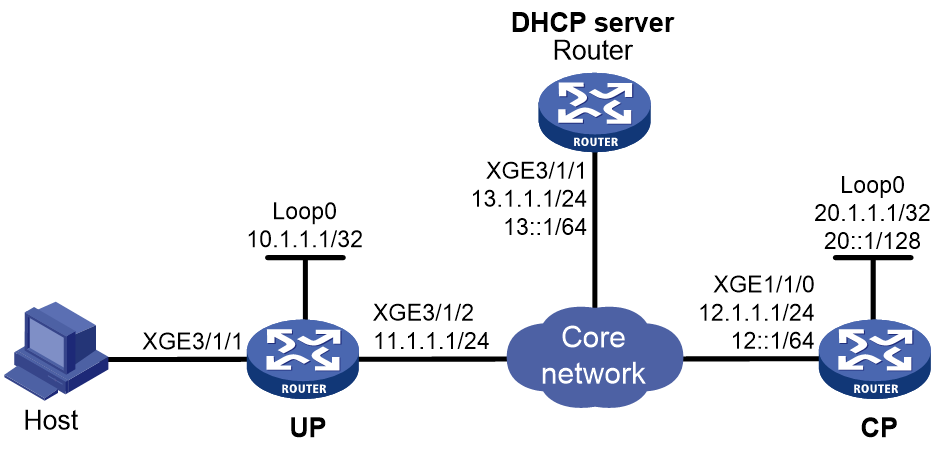
Prerequisites
Configure IP addresses for interfaces, and make sure the devices can reach each other at Layer 3. (Details not shown.)
Configure a management channel, control channel, and protocol channel between a CP and a UP. (Details not shown.)
Procedure
1. Configure the UP.
# Configure the UP to operate in user plane mode.
<UP> system-view
[UP] work-mode user-plane
2. Configure the CP:
a. Configure the DHCP server:
# Configure remote BAS IP address pool pool1.
<CP> system-view
[CP] ip pool pool1 bas remote
[CP-ip-pool-pool1] gateway 1.1.1.1 16
[CP-ip-pool-pool1] forbidden-ip 1.1.1.1
[CP-ip-pool-pool1] remote-server 13.1.1.1
[CP-ip-pool-pool1] binding up-id 1024
[CP-ip-pool-pool1] quit
# Configure remote BAS IPv6 address pool pool1.
[CP] ipv6 pool pool1 bas remote
[CP-ipv6-pool-pool1] gateway-list 1::1
[CP-ipv6-pool-pool1] network 1::/64 export-route
[CP-ipv6-pool-pool1] forbidden-address 1::1
[CP-ipv6-pool-pool1] remote-server 13::1
[CP-ipv6-pool-pool1] dhcpv6-relay source-address interface loopback 0
[CP-ipv6-pool-pool1] binding up-id 1024
[CP-ipv6-pool-pool1] quit
# Enable the DHCP relay agent on Remote-XGE 1024/3/1/1.
[CP] interface remote-xge 1024/3/1/1
[CP–Remote-XGE1024/3/1/1] dhcp select relay
[CP–Remote-XGE1024/3/1/1] ipv6 dhcp select relay
[CP–Remote-XGE1024/3/1/1] ipv6 dhcp relay release-agent
# Automatically generate a link-local address for Remote-XGE 1024/3/1/1. The IPv6 link-local address is to be used as the gateway of users.
[CP–Remote-XGE1024/3/1/1] ipv6 address auto link-local
# Enable Remote-XGE1024/3/1/1 to advertise RA messages.
[CP–Remote-XGE1024/3/1/1] undo ipv6 nd ra halt
[CP–Remote-XGE1024/3/1/1] quit
b. Configure a local user.
# Create a PPPoE user.
[CP] local-user user1 class network
[CP-luser-network-user1] password simple 123456TESTplat&!
[CP-luser-network-user1] service-type ppp
[CP-luser-network-user1] quit
c. Configure an ISP domain.
# In ISP domain dm1, perform local AAA for users and authorize address pools.
[CP] domain name dm1
[CP-isp-dm1] authentication ppp local
[CP-isp-dm1] accounting ppp local
[CP-isp-dm1] authorization ppp local
[CP-isp-dm1] authorization-attribute ip-pool pool1
[CP-isp-dm1] authorization-attribute ipv6-pool pool1
[CP-isp-dm1] quit
d. Configure the PPPoE server:
# Configure Virtual-Template 1 to use CHAP for authenticating the peer.
[CP] interface virtual-template 1
[CP-Virtual-Template1] ppp authentication-mode chap domain dm1
# Enable Virtual-Template 1 to advertise RA messages. Set the managed address configuration flag (M) to 1 in RA advertisements to be sent. Set the other stateful configuration flag (O) to 1 in RA advertisements to be sent on Virtual-Template 1.
[CP-Virtual-Template1] undo ipv6 nd ra halt
[CP-Virtual-Template1] ipv6 nd autoconfig managed-address-flag
[CP-Virtual-Template1] ipv6 nd autoconfig other-flag
[CP-Virtual-Template1] quit
# Enable the PPPoE server on Remote-XGE 1024/3/1/1, and bind the interface to VT interface 1.
[CP] interface remote-xge 1024/3/1/1
[CP-Remote-XGE1024/3/1/1] pppoe-server bind virtual-template 1
[CP-Remote-XGE1024/3/1/1] quit
3. Configure the router (DHCP server):
¡ Configure the IP address pool:
# Enable DHCP.
<Router> system-view
[Router] dhcp enable
# Create IP address pool pool1, and configure the IP subnet, gateway address, and DNS server address for DHCP clients.
[Router] ip pool pool1
[Router-ip-pool-pool1] network 1.1.0.0 16
[Router-ip-pool-pool1] gateway-list 1.1.1.1
[Router-ip-pool-pool1] dns-list 8.8.8.8
[Router-ip-pool-pool1] forbidden-ip 1.1.1.1
[Router-ip-pool-pool1] quit
# Configure the default route to the CP.
[Router] ip route-static 0.0.0.0 0 12.1.1.1
¡ Configure an IPv6 address pool:
# Create IPv6 address pool pool2, and configure the IPv6 subnet and DNS server address for DHCP clients.
[Router] ipv6 pool pool2
[Router-ipv6-pool-pool2] network 1::/64
[Router-ipv6-pool-pool2] dns-server 8::8
[Router-ipv6-pool-pool2] forbidden-address 1::1
[Router-ipv6-pool-pool2] quit
# Enable the DHCPv6 server on Ten-GigabitEthernet 3/1/1.
[Router] interface ten-gigabitethernet 3/1/1
[Router-Ten-GigabitEthernet3/1/1] ipv6 dhcp select server
[Router-Ten-GigabitEthernet3/1/1] quit
# Configure the default route to the CP.
[Router] ipv6 route-static :: 0 12::1
Verifying the configuration
# Display the online PPPoE user information on the CP.
[CP] display access-user interface remote-xge 1024/3/1/1
Slot 97:
UserID Interface IP address MAC address S-/C-VLAN
Username Access type
IPv6 address
0x1 R-XGE1024/3/1/1 1.1.0.1 000c-29a6-b656 -/-
user1 PPPoE
1::2
Example: Configuring the PPPoE server to assign IPv6 addresses through the NDRA method (prefixes authorized by AAA)
Network configuration
As shown in Figure 22, the CP and UP together act as the PPPoE server. Configure the PPPoE server to advertise the following information to the host:
· IPv6 prefix in RA messages.
· IPv6 interface identifier during IPv6CP negotiation.
The host uses the IPv6 prefix and IPv6 interface identifier to generate an IPv6 global unicast address. The IPv6 address prefixes in RA packets are authorized prefixes.

Prerequisites
Configure IP addresses for interfaces, and make sure the devices can reach each other at Layer 3. (Details not shown.)
Configure a management channel, control channel, and protocol channel between a CP and a UP. (Details not shown.)
Procedure
1. Configure the UP.
# Configure the UP to operate in user plane mode.
<UP> system-view
[UP] work-mode user-plane
2. Configure the CP:
# Create Virtual-Template 1.
<CP> system-view
[CP] interface virtual-template 1
# Configure Virtual-Template 1 to use CHAP to authenticate the peer.
[CP-Virtual-Template1] ppp authentication-mode chap domain dm1
# Enable Virtual-Template 1 to advertise RA messages.
[CP-Virtual-Template1] undo ipv6 nd ra halt
[CP-Virtual-Template1] quit
# Configure Remote-XGE 1024/3/1/1 to automatically generate an IPv6 link-local address.
CP] interface remote-xge 1024/3/1/1
[CP-Remote-XGE1024/3/1/1] ipv6 address auto link-local
# Enable Remote-XGE1024/3/1/1 to advertise RA messages.
[CP-Remote-XGE1024/3/1/1] undo ipv6 nd ra halt
# Enable the PPPoE sever on Remote-XGE 1024/3/1/1, and bind the interface to Virtual-Template 1.
[CP-Remote-XGE1024/3/1/1] pppoe-server bind virtual-template 1
[CP-Remote-XGE1024/3/1/1] quit
# (Applicable only to advertising prefix subnet routes.) Create an IPv6 address pool and enter its view. Specify the subnet for DHCPv6 clients and advertise the subnet route.
[CP] ipv6 pool pool1 bas local
[CP-ipv6-pool-pool1] network 10::/64 export-route
[CP-ipv6-pool-pool1] quit
# Configure a PPPoE user.
[CP] local-user user1 class network
[CP-luser-network-user1] password simple 123456TESTplat&!
[CP-luser-network-user1] service-type ppp
[CP-luser-network-user1] quit
# Configure local AAA for the PPP users in the ISP domain dm1.
[CP] domain name dm1
[CP-isp-dm1] authentication ppp local
[CP-isp-dm1] accounting ppp local
[CP-isp-dm1] authorization ppp local
# Configure an IPv6 prefix and a DNS server authorized to the users in the ISP domain dm1.
[CP-isp-dm1] authorization-attribute ipv6-prefix 10:: 64
[CP-isp-dm1] authorization-attribute primary-dns ipv6 8::8
[CP-isp-dm1] quit
Verifying the configuration
# Display PPP user information on Remote-XGE 1024/3/1/1.
[CP] display access-user interface remote-xge 1024/3/1/1
Slot 97:
UserID Interface IP address MAC address S-/C-VLAN
Username Access type
IPv6 address
0x6 R-XGE1024/3/1/1 - 001b-21a8-0949 -/-
user1 PPPoE
10::F85B:7EE1:1410:74C9
Example: Configuring the PPPoE server to assign IPv6 addresses through the NDRA method (prefixes authorized by ND prefix pool)
Network configuration
As shown in Figure 23, the CP and UP together act as the PPPOE server. Configure the PPPoE server to advertise the following information to the host:
· IPv6 prefix in RA messages.
· IPv6 interface identifier during IPv6CP negotiation.
The host uses the IPv6 prefix and IPv6 interface identifier to generate an IPv6 global unicast address. The IPv6 address prefixes in RA packets are authorized prefixes.

Prerequisites
Configure IP addresses for interfaces, and make sure the devices can reach each other at Layer 3. (Details not shown.)
Configure a management channel, control channel, and protocol channel between a CP and a UP. (Details not shown.)
Procedure
1. Configure the UP.
# Configure the UP to operate in user plane mode.
<UP> system-view
[UP] work-mode user-plane
2. Configure the CP:
# Create Virtual-Template 1.
<CP> system-view
[CP] interface virtual-template 1
# Configure Virtual-Template 1 to use CHAP to authenticate the peer.
[CP-Virtual-Template1] ppp authentication-mode chap domain dm1
# Enable Virtual-Template 1 to advertise RA messages.
[CP-Virtual-Template1] undo ipv6 nd ra halt
[CP-Virtual-Template1] quit
# Configure Remote-XGE 1024/3/1/1 to automatically generate an IPv6 link-local address.
[CP] interface remote-xge 1024/3/1/1
[CP-Remote-XGE1024/3/1/1] ipv6 address auto link-local
# Enable Remote-XGE 1024/3/1/1 to advertise RA messages.
[CP-Remote-XGE1024/3/1/1] undo ipv6 nd ra halt
# Enable the PPPoE sever on Remote-XGE 1024/3/1/1, and bind the interface to Virtual-Template 1.
[CP-Remote-XGE1024/3/1/1] pppoe-server bind virtual-template 1
[CP-Remote-XGE1024/3/1/1] quit
# Create prefix pool 1, and specify the prefix 10::/16 with the assigned prefix length 32. Prefix pool 1 contains 65536 prefixes from 10:1::/32 to 10:FFFF::/32.
[CP] ipv6 dhcp prefix-pool 1 prefix 10::/16 assign-len 32
# Create ODAP IPv6 address pool named pool1, and apply prefix pool 1 to the address pool. Specify IPv6 prefix length 64 for the ODAPv6 client to assign IPv6 prefix ranges.
[CP] ipv6 pool pool1 odap
[CP-ipv6-pool-pool1] prefix-pool 1
[CP-ipv6-pool-pool1] dynamic prefix assign-length 64
[CP-ipv6-pool-pool1] quit
# Configure a PPPoE user.
[CP] local-user user1 class network
[CP-luser-network-user1] password simple 123456TESTplat&!
[CP-luser-network-user1] service-type ppp
[CP-luser-network-user1] quit
# Configure local AAA for the PPP users in the ISP domain dm1.
[CP] domain name dm1
[CP-isp-dm1] authentication ppp local
[CP-isp-dm1] accounting ppp local
[CP-isp-dm1] authorization ppp local
# Authorize ND prefix pool pool1 and the primary DNS server to users in the ISP domain dm1.
[CP-isp-dm1] authorization-attribute ipv6-nd-prefix-pool pool1
[CP-isp-dm1] authorization-attribute primary-dns ipv6 8::8
[CP-isp-dm1] quit
Verifying the configuration
# Display PPP user information on Remote-XGE 1024/3/1/1.
[CP] display access-user interface remote-xge 1024/3/1/1
Slot 97:
UserID Interface IP address MAC address S-/C-VLAN
Username Access type
IPv6 address
0x6 R-XGE1024/3/1/1 - 001b-21a8-0949 -/-
user1 PPPoE
10::F85B:7EE1:1410:74C9
Example: Configuring the PPPoE server to assign IPv6 addresses through the IA_NA method
Network configuration
As shown in Figure 24, the CP and UP together act as the PPPoE server. Configure the PPPoE server to assign an IPv6 address to the host through DHCPv6.

Prerequisites
Configure IP addresses for interfaces, and make sure the devices can reach each other at Layer 3. (Details not shown.)
Configure a management channel, control channel, and protocol channel between a CP and a UP. (Details not shown.)
Procedure
1. Configure the UP.
# Configure the UP to operate in user plane mode.
<UP> system-view
[UP] work-mode user-plane
2. Configure the CP:
# Create Virtual-Template 1.
<CP> system-view
[CP] interface virtual-template 1
# Configure Virtual-Template 1 to use CHAP to authenticate the peer.
[CP-Virtual-Template1] ppp authentication-mode chap domain dm1
# Enable Virtual-Template 1 to advertise RA messages.
[CP-Virtual-Template1] undo ipv6 nd ra halt
# Set the managed address configuration flag (M) to 1 in RA advertisements to be sent.
[CP-Virtual-Template1] ipv6 nd autoconfig managed-address-flag
# Set the other stateful configuration flag (O) to 1 in RA advertisements to be sent on Virtual-Template 1.
[CP-Virtual-Template1] ipv6 nd autoconfig other-flag
[CP-Virtual-Template1] quit
# Configure Remote-XGE 1024/3/1/1 to automatically generate an IPv6 link-local address.
[CP] interface remote-xge 1024/3/1/1
[CP-Remote-XGE1024/3/1/1] ipv6 address auto link-local
# Enable Remote-XGE 1024/3/1/1 to advertise RA messages.
[CP-Ten-GigabitEthernet3/1/1] undo ipv6 nd ra halt
# Enable the DHCPv6 server on Remote-XGE 1024/3/1/1.
[CP-Remote-XGE1024/3/1/1] undo ipv6 nd ra halt
# Enable the PPPoE sever on Remote-XGE 1024/3/1/1, and bind the interface to Virtual-Template 1.
[CP-Remote-XGE1024/3/1/1] pppoe-server bind virtual-template 1
[CP-Remote-XGE1024/3/1/1] quit
# Configure ODAP IPv6 address pool pool1.
[CP] ipv6 pool pool1 odap
[CP-ipv6-pool-pool1] network 1::/32 export-route
[CP-ipv6-pool-pool1] dynamic address assign-length 64
[CP-ipv6-pool-pool1] forbidden-address 1::1
[CP-ipv6-pool-pool1] dns-server 8::8
[CP-ipv6-pool-pool1] quit
# Configure a PPPoE user.
[CP] local-user user1 class network
[CP-luser-network-user1] password simple 123456TESTplat&!
[CP-luser-network-user1] service-type ppp
[CP-luser-network-user1] quit
# In the ISP domain dm1, perform local AAA for PPP users, and authorize an address pool to PPP users.
[CP] domain name dm1
[CP-isp-dm1] authentication ppp local
[CP-isp-dm1] accounting ppp local
[CP-isp-dm1] authorization ppp local
[CP-isp-dm1] authorization-attribute ipv6-pool pool1
[CP-isp-dm1] quit
Verifying the configuration
# Display PPP user information on Remote-XGE 1024/3/1/1.
[CP] display access-user interface remote-xge 1024/3/1/1
Slot 97:
UserID Interface IP address MAC address S-/C-VLAN
Username Access type
IPv6 address
0x9 R-XGE1024/3/1/1 - 001b-21a8-0949 -/-
user1 PPPoE
1::2
Example: Configuring the PPPoE server to assign IPv6 addresses through the IA_PD method
Network configuration
As shown in Figure 12, the CP and UP together act as the PPPoE server. Configure the PPPoE server to assign a prefix to Router through DHCPv6. Router then assigns the prefix to the host for it to generate an IPv6 address.
Figure 25 Network diagram

Prerequisites
Configure IP addresses for interfaces, and make sure the devices can reach each other at Layer 3. (Details not shown.)
Configure a management channel, control channel, and protocol channel between a CP and a UP. (Details not shown.)
Procedure
1. Configure the UP.
# Configure the UP to operate in user plane mode.
<UP> system-view
[UP] work-mode user-plane
2. Configure the CP:
# Create Virtual-Template 1.
<CP> system-view
[CP] interface virtual-template 1
# Configure Virtual-Template 1 to use CHAP to authenticate the peer.
[CP-Virtual-Template1] ppp authentication-mode chap domain dm1
# Enable Virtual-Template 1 to advertise RA messages.
[CP-Virtual-Template1] undo ipv6 nd ra halt
[CP-Virtual-Template1] quit
# Configure Remote-XGE 1024/3/1/1 to automatically generate an IPv6 link-local address.
[CP] interface remote-xge 1024/3/1/1
[CP-Remote-XGE1024/3/1/1] ipv6 address auto link-local
# Enable Remote-XGE 1024/3/1/1 to advertise RA messages.
[CP-Remote-XGE1024/3/1/1] undo ipv6 nd ra halt
# Enable the DHCPv6 server on Remote-XGE 1024/3/1/1.
[CP-Remote-XGE1024/3/1/1] ipv6 dhcp select server
# Enable the PPPoE sever on Remote-XGE 1024/3/1/1, and bind the interface to Virtual-Template 1.
[CP-Remote-XGE1024/3/1/1] pppoe-server bind virtual-template 1
[CP-Remote-XGE1024/3/1/1] quit
# Create prefix pool 6, and specify prefix 20::/16 with assigned prefix length 32. Prefix pool 6 contains 65536 prefixes from 20:1::/32 to 20:FFFF::/32.
[CP] ipv6 dhcp prefix-pool 6 prefix 20::/16 assign-len 32
# Create ODAP IPv6 address pool pool1, and apply prefix pool 6 to address pool pool1. Specify IPv6 prefix length 64 for the ODAPv6 client to assign IPv6 prefix ranges.
[CP] ipv6 pool pool1 odap
[CP-ipv6-pool-pool1] prefix-pool 6
[CP-ipv6-pool-pool1] dynamic prefix assign-length 64
[CP-ipv6-pool-pool1] quit
# Configure a PPPoE user.
[CP] local-user user1 class network
[CP-luser-network-user1] password simple 123456TESTplat&!
[CP-luser-network-user1] service-type ppp
[CP-luser-network-user1] quit
# In the ISP domain dm1, perform local AAA for PPP users, and authorize an address pool to PPP users.
[CP] domain name dm1
[CP-isp-dm1] authentication ppp local
[CP-isp-dm1] accounting ppp local
[CP-isp-dm1] authorization ppp local
[CP-isp-dm1] authorization-attribute ipv6-pool pool1
[CP-isp-dm1] quit
3. Configure Router (PPPoE client):
# Enable bundle DDR on interface Dialer 1.
<Router> system-view
[Router] interface dialer 1
[Router-Dialer1] dialer bundle enable
# On Dialer 1, configure the CHAP username and password sent from Router to CP as user1 and 123456TESTplat&! when Router is authenticated by CP by using CHAP.
[Router-Dialer1] ppp chap user user1
[Router-Dialer1] ppp chap password simple 123456TESTplat&!
# Configure the PPPoE session to operate in permanent mode.
[Router-Dialer1] dialer timer idle 0
# Set the DDR auto-dial interval to 60 seconds.
[Router-Dialer1] dialer timer autodial 60
# Configure Dialer 1 to use DHCPv6 to obtain an IPv6 address and other configuration parameters.
[Router-Dialer1] ipv6 address dhcp-alloc
# Configure Dialer 1 as a DHCPv6 client for IPv6 prefix acquisition. Configure the DHCPv6 client to assign ID 1 to the obtained IPv6 prefix.
[Router-Dialer1] ipv6 dhcp client pd 1
[Router-Dialer1] quit
# Configure a PPPoE session corresponding to Dialer bundle 1, which corresponds to Dialer 1.
[Router] interface ten-gigabitethernet 3/1/2
[Router-Ten-GigabitEthernet3/1/2] pppoe-client dial-bundle-number 1
[Router-Ten-GigabitEthernet3/1/2] quit
# Configure a default route.
[Router] ipv6 route-static :: 0 dialer 1
# Enable Ten-GigabitEthernet3/1/1 to advertise RA messages.
[Router] interface ten-gigabitethernet 3/1/1
[Router-Ten-GigabitEthernet3/1/1] undo ipv6 nd ra halt
# Configure Ten-GigabitEthernet3/1/1 to dynamically obtain IPv6 prefix 1 (use IPv6 prefix 1 to generate IPv6 address 20::123:1:1, which must be configured as the gateway address for users attached to Router) and advertise IPv6 prefix 1 to endpoints through RA messages.
[Router-Ten-GigabitEthernet3/1/1] ipv6 address 1 123::123:1:1/64
[Router-Ten-GigabitEthernet3/1/1] quit
Verifying the configuration
# Verify that CP has assigned a prefix to Router through DHCPv6.
[CP] display ipv6 dhcp server pd-in-use
Pool: pool1
IPv6 prefix Type Lease expiration DUID
20::/32 Auto(C) Expires after 2100 31303234
Slot 97:
Pool: pool1
IPv6 prefix Type Lease expiration DUID
20::/64 Auto(C) Expires after 2100 0540c4d7310107
# Display information about prefixes on Router.
[Router] display ipv6 prefix
Number Prefix Type
1 20::/64 Dynamic
The output shows that Router has created prefix 1 based on the ipv6 dhcp client pd 1 command after obtaining a prefix from CP.
Then, Router can assign the prefix 20::/64 to the host who uses the prefix to generate an IPv6 global unicast address.
Example: Configuring the PPPoE server to assign IP addresses to dual-stack users through remote DHCPv4+NDRA+IA_PD
Network configuration
As shown in Figure 13, the CP and UP act as the PPPoE server. Configure the PPPoE server as follows:
· On the IPv4 network:
¡ Router C acts as a remote DHCP server.
¡ Router A accesses the PPPoE server through PPPoE.
¡ The PPPoE server also acts as the DHCP relay agent to request an IPv4 address from the remote DHCP server.
· On the IPv6 network:
¡ Configure the PPPoE server to assign an IPv6 prefix from the ND prefix pool to the WAN interface (Dialer 1 in this example) of Router A through NDRA.
¡ Configure the PPPoE server to assign a prefix to Router A through IA_PD. Router A then assigns the prefix to the host for it to generate an IPv6 address.
Figure 26 Network diagram
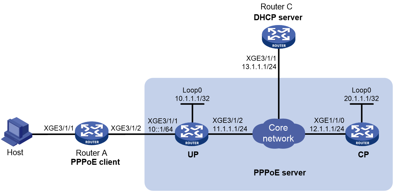
Prerequisites
Configure IP addresses for interfaces, and make sure the devices can reach each other at Layer 3. (Details not shown.)
Configure a management channel, control channel, and protocol channel between a CP and a UP. (Details not shown.)
Procedure
1. Configure Router C (DHCP server):
# Enable DHCP.
<RouterC> system-view
[RouterC] dhcp enable
# Create IP address pool pool1. Configure the network for IP address allocation, the gateway address, and the DNS server address in the address pool.
[RouterC] ip pool pool1
[RouterC-ip-pool-pool1] network 1.1.1.0 24
[RouterC-ip-pool-pool1] gateway-list 1.1.1.1
[RouterC-ip-pool-pool1] dns-list 8.8.8.8
# Exclude IP address 1.1.1.1 from IP address allocation.
[RouterC-ip-pool-pool1] forbidden-ip 1.1.1.1
[RouterC-ip-pool-pool1] quit
# Configure the default route to the PPPoE server.
[RouterC] ip route-static 0.0.0.0 0 13.1.1.2
2. Configure the UP.
# Configure the UP to operate in user plane mode.
<UP> system-view
[UP] work-mode user-plane
3. Configure the CP:
# Create Virtual-Template 1.
<CP> system-view
[CP] interface virtual-template 1
# Configure Virtual-Template 1 to use CHAP to authenticate the peer.
[CP-Virtual-Template1] ppp authentication-mode chap domain dm1
# Enable Virtual-Template 1 to advertise RA messages.
[CP-Virtual-Template1] undo ipv6 nd ra halt
[CP-Virtual-Template1] quit
# Configure Remote-XGE 1024/3/1/1 to automatically generate an IPv6 link-local address.
[CP] interface remote-xge 1024/3/1/1
[CP-Remote-XGE1024/3/1/1] ipv6 address auto link-local
# Enable Remote-XGE 1024/3/1/1 to advertise RA messages.
[CP-Remote-XGE1024/3/1/1] undo ipv6 nd ra halt
# Enable the DHCP relay agent on Remote-XGE 1024/3/1/1.
[CP-Remote-XGE1024/3/1/1] dhcp select relay
# Enable the DHCPv6 server on Remote-XGE 1024/3/1/1.
[CP-Remote-XGE1024/3/1/1] ipv6 dhcp select server
# Enable the PPPoE sever on Remote-XGE 1024/3/1/1, and bind the interface to Virtual-Template 1.
[CP-Remote-XGE1024/3/1/1] pppoe-server bind virtual-template 1
[CP-Remote-XGE1024/3/1/1] quit
# (For DHCPv4) Create remote BAS IP address pool pool1. Specify the subnet for address allocation in the address pool. Exclude IP address 1.1.1.1 from address allocation. Specify a DHCP server for the IP pool.
[CP] ip pool pool1 bas remote
[CP-ip-pool-pool1] gateway 1.1.1.1 24
[CP-ip-pool-pool1] forbidden-ip 1.1.1.1
[CP-ip-pool-pool1] remote-server 10.1.1.1
[CP-ip-pool-pool1] quit
# (For NDRA) Create DHCPv6 prefix pool 1, and specify the prefix 10::/16 with the assigned prefix length 32. Prefix pool 1 contains 65536 prefixes from 10:1::/32 to 10:FFFF::/32.
[CP] ipv6 dhcp prefix-pool 1 prefix 10::/16 assign-len 32
# Create ODAP IPv6 address pool named ndra, and apply prefix pool 1 to the IPv6 address pool. Specify IPv6 prefix length 64 for the ODAPv6 client to assign IPv6 prefix ranges.
[CP] ipv6 pool ndra odap
[CP-ipv6-pool-ndra] prefix-pool 1
[CP-ipv6-pool-ndra] dynamic prefix assign-length 64
[CP-ipv6-pool-ndra] quit
# (For IA_PD) Create prefix pool 6, and specify prefix 20::/16 with assigned prefix length 32. Prefix pool 6 contains 65536 prefixes from 20:1::/32 to 20:FFFF::/32.
[CP] ipv6 dhcp prefix-pool 6 prefix 20::/16 assign-len 32
# Create ODAP IPv6 address pool iapd, and apply prefix pool 6 to address pool iapd. Specify IPv6 prefix length 64 for the ODAPv6 client to assign IPv6 prefix ranges.
[CP] ipv6 pool iapd odap
[CP-ipv6-pool-iapd] prefix-pool 6
[CP-ipv6-pool-iapd] dynamic prefix assign-length 64
[CP-ipv6-pool-iapd] quit
# Configure a PPPoE user.
[CP] local-user user1 class network
[CP-luser-network-user1] password simple 123456TESTplat&!
[CP-luser-network-user1] service-type ppp
[CP-luser-network-user1] quit
# In the ISP domain dm1, perform local AAA for PPP users, and authorize an IP address pool, ND prefix pool, IPv6 DNS address, and address pool to PPP users.
[CP] domain name dm1
[CP-isp-dm1] authentication ppp local
[CP-isp-dm1] accounting ppp local
[CP-isp-dm1] authorization ppp local
[CP-isp-dm1] authorization-attribute ip-pool pool1
[CP-isp-dm1] authorization-attribute ipv6-nd-prefix-pool ndra
[CP-isp-dm1] authorization-attribute primary-dns ipv6 8::8
[CP-isp-dm1] authorization-attribute ipv6-pool iapd
[CP-isp-dm1] quit
4. Configure Router A (PPPoE client):
# Enable bundle DDR on interface Dialer 1.
<RouterA> system-view
[RouterA] interface dialer 1
[RouterA-Dialer1] dialer bundle enable
# On Dialer 1, configure the CHAP username and password sent from Router A to CP as user1 and 123456TESTplat&! when Router A is authenticated by CP by using CHAP.
[RouterA-Dialer1] ppp chap user user1
[RouterA-Dialer1] ppp chap password simple 123456TESTplat&!
# Configure the PPPoE session to operate in permanent mode.
[RouterA-Dialer1] dialer timer idle 0
# Set the DDR auto-dial interval to 60 seconds.
[RouterA-Dialer1] dialer timer autodial 60
# (For IPv4) Configure Dialer 1 to obtain an IP address through automatic negotiation. Enable Dialer 1 to request the peer for a DNS server IP address. Configure Dialer 1 to accept the DNS server IP addresses assigned by the peer even though it does not request the peer for the DNS server IP addresses.
[RouterA-Dialer1] ip address ppp-negotiate
[RouterA-Dialer1] ppp ipcp dns request
[RouterA-Dialer1] ppp ipcp dns admit-any
# (For IPv4) Translate the source addresses of the packets from internal hosts into the IP address of Dialer 1.
[RouterA-Dialer1] nat outbound
# (For NDRA) Configure Dialer 1 to automatically generate an IPv6 global unicast address.
[RouterA-Dialer1] ipv6 address auto
# (For IA_PD) Configure Dialer 1 to use DHCPv6 to obtain an IPv6 address and other configuration parameters.
[RouterA-Dialer1] ipv6 address dhcp-alloc
# (For IA_PD) Configure Dialer 1 as a DHCPv6 client for IPv6 prefix acquisition. Configure the DHCPv6 client to assign ID 1 to the obtained IPv6 prefix.
[RouterA-Dialer1] ipv6 dhcp client pd 1
[[RouterA-Dialer1] quit
# Configure a PPPoE session corresponding to Dialer bundle 1, which corresponds to Dialer 1.
[RouterA] interface ten-gigabitethernet 3/1/2
[RouterA-Ten-GigabitEthernet3/1/2] pppoe-client dial-bundle-number 1
[RouterA-Ten-GigabitEthernet3/1/2] quit
# Configure default routes.
[RouterA] ip route-static 0.0.0.0 0 dialer 1
[RouterA] ipv6 route-static :: 0 dialer 1
# Enable DHCP.
[RouterA] dhcp enable
# Create IP address pool pool1.
[RouterA] ip pool pool1
[RouterA-ip-pool-pool1] network 192.168.1.0 24
[RouterA-ip-pool-pool1] gateway-list 192.168.1.1
[RouterA-ip-pool-pool1] dns-list 8.8.8.8
# Exclude IP address 192.168.1.1 from address allocation.
[RouterA-ip-pool-pool1] forbidden-ip 192.168.1.1
[RouterA-ip-pool-pool1] quit
# Assign an IP address to Ten-GigabitEthernet 3/1/1, the IPv4 gateway address for internal network users.
[RouterA] interface ten-gigabitethernet 3/1/1
[RouterA-Ten-GigabitEthernet3/1/1] ip address 192.168.1.1 24
# Enable Ten-GigabitEthernet 3/1/1 to advertise RA messages.
RouterA] interface ten-gigabitethernet 3/1/1
[RouterA-Ten-GigabitEthernet3/1/1] undo ipv6 nd ra halt
# Configure Ten-GigabitEthernet 3/1/1 to dynamically obtain IPv6 prefix 1 (use IPv6 prefix 1 to generate IPv6 address 20::123:1:1, which must be configured as the gateway address for users attached to Router A) and advertise IPv6 prefix 1 to endpoints through RA messages.
[RouterA-Ten-GigabitEthernet3/1/1] ipv6 address 1 123::123:1:1/64
[RouterA-Ten-GigabitEthernet3/1/1] quit
Verifying the configuration
# Verify that CP has assigned a prefix to Router A through DHCPv6. After Router A is configured and accesses CP through username user1 and password 123456TESTplat&! through PPPoE, CP obtains an IPv4 address through DHCPv4 and automatically generates a IPv6 global unicast address through the authorized IPv6 prefix and IPv6 interface identifier obtained through IPv6CP negotiation.
[CP] display access-user interface remote-xge 1024/3/1/1
Slot 97:
UserID Interface IP address MAC address S-/C-VLAN
Username Access type
IPv6 address
0x6 R-XGE1024/3/1/1 1.1.1.2 001b-21a8-0949 -/-
user1 PPPoE
10::F85B:7EE1:1410:74C9
# Verify that CP has assigned a prefix to Router A through DHCPv6.
[CP] display ipv6 dhcp server pd-in-use
Pool: iapd
IPv6 prefix Type Lease expiration DUID
20::/32 Auto(C) Expires after 2100 31303234
Pool: ndra
IPv6 prefix Type Lease expiration DUID
10::/32 Auto(C) Expires after 2100 31303234
Slot 97:
Pool: iapd
IPv6 prefix Type Lease expiration DUID
20::/64 Auto(C) Expires after 2100 0540c4d7310107
Pool: ndra
IPv6 prefix Type Lease expiration DUID
10::/64 Auto(C) Expires after 2100 0640c4d7310107
# Display information about prefixes on Router A.
[RouterA] display ipv6 prefix
Number Prefix Type
1 20::/64 Dynamic
The output shows that Router A has created prefix 1 based on the ipv6 dhcp client pd 1 command after obtaining a prefix from CP.
Then, Router A can assign the prefix 20::/64 to the host who uses the prefix to generate an IPv6 global unicast address.
Example: Configuring the PPPoE server to assign IPv6 addresses through the IA_NA+IA_PD method
Network configuration
As shown in Figure 14, the CP and UP act as the PPPoE server. Configure the PPPoE server as follows:
· Configure the PPPoE server to assign an IPv6 global unicast address to the WAN interface (Dialer 1 in this example) of Router.
· Configure the PPPoE server to assign a prefix to Router through IA_PD. Router then assigns the prefix to the host for it to generate an IPv6 address.
Figure 27 Network diagram
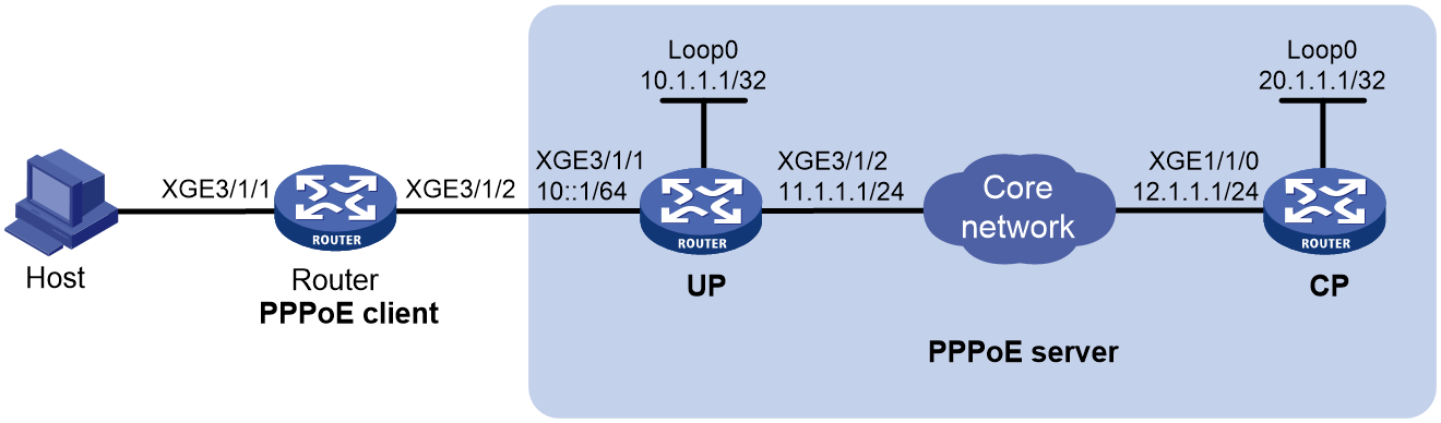
Prerequisites
Configure IP addresses for interfaces, and make sure the devices can reach each other at Layer 3. (Details not shown.)
Configure a management channel, control channel, and protocol channel between a CP and a UP. (Details not shown.)
Procedure
1. Configure the UP.
# Configure the UP to operate in user plane mode.
<UP> system-view
[UP] work-mode user-plane
2. Configure CP (PPPoE server):
# Create Virtual-Template 1.
<CP> system-view
[CP] interface virtual-template 1
# Configure Virtual-Template 1 to use CHAP to authenticate the peer.
[CP-Virtual-Template1] ppp authentication-mode chap domain dm1
# Enable Virtual-Template 1 to advertise RA messages.
[CP-Virtual-Template1] undo ipv6 nd ra halt
# Set the managed address configuration flag (M) to 1 in RA advertisements to be sent.
[CP-Virtual-Template1] ipv6 nd autoconfig managed-address-flag
# Set the other stateful configuration flag (O) to 1 in RA advertisements to be sent on Virtual-Template 1.
[CP-Virtual-Template1] ipv6 nd autoconfig other-flag
[CP-Virtual-Template1] quit
# Configure Remote-XGE 1024/3/1/1 to automatically generate an IPv6 link-local address.
[CP] interface remote-xge 1024/3/1/1
[CP-Remote-XGE1024/3/1/1] ipv6 address auto link-local
# Enable Remote-XGE 1024/3/1/1 to advertise RA messages.
[CP-Remote-XGE1024/3/1/1] undo ipv6 nd ra halt
# Enable the DHCPv6 server on Remote-XGE 1024/3/1/1.
[CP-Remote-XGE1024/3/1/1] ipv6 dhcp select server
# Enable the PPPoE sever on Remote-XGE 1024/3/1/1, and bind the interface to Virtual-Template 1.
[CP-Remote-XGE1024/3/1/1] pppoe-server bind virtual-template 1
[CP-Remote-XGE1024/3/1/1] quit
# (For IA_PD) Create prefix pool 6, and specify prefix 20::/16 with assigned prefix length 32. Prefix pool 6 contains 65536 prefixes from 20:1::/32 to 20:FFFF::/32.
[CP] ipv6 dhcp prefix-pool 6 prefix 20::/16 assign-len 32
# Create ODAP IPv6 address pool named pool1.
[CP] ipv6 pool pool1 odap
# (For IA_NA) Configure IPv6 address pool pool1 with network 1::/32 for dynamic allocation, and specify the prefix length as 64 for the allocated IPv6 addresses. Exclude IPv6 address 1::1 from address allocation, and specify the DNS server address as 8::8.
[CP-ipv6-pool-pool1] network 1::/32 export-route
[CP-ipv6-pool-pool1] dynamic address assign-length 64
[CP-ipv6-pool-pool1] forbidden-address 1::1
[CP-ipv6-pool-pool1] dns-server 8::8
# (For IA_PD) Apply prefix pool 6 to address pool pool1. Specify IPv6 prefix length 64 for the client to assign IPv6 prefix ranges.
[CP-ipv6-pool-pool1] prefix-pool 6
[CP-ipv6-pool-pool1] dynamic prefix assign-length 64
[CP-ipv6-pool-pool1] quit
# Configure a PPPoE user.
[CP] local-user user1 class network
[CP-luser-network-user1] password simple 123456TESTplat&!
[CP-luser-network-user1] service-type ppp
[CP-luser-network-user1] quit
# In the ISP domain dm1, perform local AAA for PPP users, and authorize an address pool to PPP users.
[CP] domain name dm1
[CP-isp-dm1] authentication ppp local
[CP-isp-dm1] accounting ppp local
[CP-isp-dm1] authorization ppp local
[CP-isp-dm1] authorization-attribute ipv6-pool pool1
[CP-isp-dm1] quit
3. Configure Router (PPPoE client):
# Enable bundle DDR on interface Dialer 1.
<Router> system-view
[Router] interface dialer 1
[Router-Dialer1] dialer bundle enable
# On Dialer 1, configure the CHAP username and password sent from Router to CP as user1 and 123456TESTplat&! when Router is authenticated by CP by using CHAP.
[Router-Dialer1] ppp chap user user1
[Router-Dialer1] ppp chap password simple 123456TESTplat&!
# Configure the PPPoE session to operate in permanent mode.
[Router-Dialer1] dialer timer idle 0
# Set the DDR auto-dial interval to 60 seconds.
[Router-Dialer1] dialer timer autodial 60
# (For IA_NA+IA_PD) Configure Dialer 1 to use DHCPv6 to obtain an IPv6 address and other configuration parameters.
[Router-Dialer1] ipv6 address dhcp-alloc
# (For IA_PD) Configure Dialer 1 as a DHCPv6 client for IPv6 prefix acquisition. Configure the DHCPv6 client to assign ID 1 to the obtained IPv6 prefix.
[Router-Dialer1] ipv6 dhcp client pd 1
[Router-Dialer1] quit
# Configure a PPPoE session corresponding to Dialer bundle 1, which corresponds to Dialer 1.
[Router] interface ten-gigabitethernet 3/1/2
[Router-Ten-GigabitEthernet3/1/2] pppoe-client dial-bundle-number 1
[Router-Ten-GigabitEthernet3/1/2] quit
# Configure a default route.
Router] ipv6 route-static :: 0 dialer 1
# Enable Ten-GigabitEthernet 3/1/1 to advertise RA messages.
Router] interface ten-gigabitethernet 3/1/1
[Router-Ten-GigabitEthernet3/1/1] undo ipv6 nd ra halt
# Configure Ten-GigabitEthernet 3/1/1 to dynamically obtain IPv6 prefix 1 (use IPv6 prefix 1 to generate IPv6 address 20::123:1:1, which must be configured as the gateway address for users attached to Router) and advertise IPv6 prefix 1 to endpoints through RA messages.
[Router-Ten-GigabitEthernet3/1/1] ipv6 address 1 123::123:1:1/64
[Router-Ten-GigabitEthernet3/1/1] quit
Verifying the configuration
# Verify that CP has assigned an IPv6 global unicast address to Router through DHCPv6 after Router is configured and accesses CP through username user1 and password 123456TESTplat&! through PPPoE.
[Router] display access-user interface remote-xge 1024/3/1/1
Slot 97:
UserID Interface IP address MAC address S-/C-VLAN
Username Access type
IPv6 address
0x9 R-XGE1024/3/1/1 - 001b-21a8-0949 -/-
user1 PPPoE
1::2
# Verify that CP has assigned a prefix to Router through DHCPv6.
[CP] display ipv6 dhcp server pd-in-use
Pool: pool1
IPv6 prefix Type Lease expiration DUID
20::/32 Auto(C) Expires after 2100 31303234
Slot 97:
Pool: pool1
IPv6 prefix Type Lease expiration DUID
20::/64 Auto(C) Expires after 2100 0540c4d7310107
# Display information about prefixes on Router.
[Router] display ipv6 prefix
Number Prefix Type
1 20::/64 Dynamic
The output shows that Router has created prefix 1 based on the ipv6 dhcp client pd 1 command after obtaining a prefix from CP.
Then, Router can assign the prefix 20::/64 to the host who uses the prefix to generate an IPv6 global unicast address.
