- Table of Contents
-
- 08-IP Multicast Configuration Guide
- 00-Preface
- 01-Multicast overview
- 02-IGMP snooping configuration
- 03-PIM snooping configuration
- 04-Multicast VLAN configuration
- 05-Multicast routing and forwarding configuration
- 06-IGMP configuration
- 07-PIM configuration
- 08-MSDP configuration
- 09-Multicast VPN configuration
- 10-MLD snooping configuration
- 11-IPv6 PIM snooping configuration
- 12-IPv6 multicast VLAN configuration
- 13-IPv6 multicast routing and forwarding configuration
- 14-MLD configuration
- 15-IPv6 PIM configuration
- Related Documents
-
| Title | Size | Download |
|---|---|---|
| 09-Multicast VPN configuration | 2.82 MB |
Basic concepts in MDT-based MVPN
Inter-AS option A MDT-based MVPN
Inter-AS option B MDT-based MVPN
Inter-AS option C MDT-based MVPN
Basic concepts in RSVP-TE-based MVPN
Inclusive tunnel establishment
Selective tunnel establishment and tunnel switchover
Basic concepts in mLDP-based MVPN
Inclusive tunnel establishment
Selective tunnel establishment and tunnel switchover
Inter-AS option A mLDP-based MVPN
Inter-AS option B mLDP-based MVPN
Inter-AS option C mLDP-based MVPN
Inclusive tunnel establishment
Selective tunnel establishment and tunnel switchover
Inter-AS option A BIER-based MVPN
Inter-AS option C BIER-based MVPN
Restrictions and guidelines: Multicast VPN configuration
Multicast VPN tasks at a glance
MDT-based MVPN tasks at a glance
RSVP-TE-based MVPN tasks at a glance
mLDP-TE-based MVPN tasks at a glance
BIER-based MVPN tasks at a glance
Prerequisites for configuring MDT-based MVPN
Enabling IP multicast routing for a VPN instance
Creating an MDT-based MVPN instance
Creating an MVPN address family
Specifying the MVPN source interface
Configuring MDT switchover parameters
Configuring the RPF vector feature
Enabling data group reuse logging
Configuring BGP MDT peers or peer groups
Limiting BGP MDT routes received from a peer or peer group
Configuring a BGP MDT route reflector
Configuring BGP MDT optimal route selection delay
Preferring routes learned from the specified peer or peer group during optimal route selection
Configuring RSVP-TE-based MVPN
Restrictions and guidelines for RSVP-TE-based MVPN
Prerequisites for configuring RSVP-TE-based MVPN
Enabling IP multicast routing for a VPN instance
Configuring BGP IPv4 MVPN route exchange
Creating an RSVP-TE-based MVPN instance
Creating an MVPN IPv4 address family
Specifying the MVPN source interface
Enabling inclusive tunnel creation
Enabling selective tunnel creation
Setting the tunnel switchover delay
Restrictions and guidelines for mLDP-based MVPN
Prerequisites for configuring mLDP-based MVPN
Enabling IP multicast routing for a VPN instance
Configuring BGP IPv4 MVPN route exchange
Configuring BGP IPv6 MVPN route exchange
Creating an mLDP-based MVPN instance
Creating an MVPN IPv4 address family
Specifying the MVPN source interface
Enabling inclusive tunnel creation
Enabling selective tunnel creation
Setting the tunnel switchover delay
Enabling inter-AS auto-discovery
Restrictions: Hardware compatibility with BIER-based MVPN
Prerequisites for configuring BIER-based MVPN
Enabling IP multicast routing for a VPN instance
Configuring BGP IPv4 MVPN route exchange
Configuring BGP IPv6 MVPN route exchange
Allowing the device to add extended community attributes to C-multicast routes sent to BGP peers
Creating a BIER-based MVPN instance
Creating an MVPN IPv4 address family
Specifying the MVPN source interface
Enabling IPv6 underlay for MVPN
Configuring multicast service prefix information
Specifying the multicast service source address
Enabling inclusive tunnel creation
Enabling selective tunnel creation
Setting the tunnel holddown timer
Enabling inter-AS auto-discovery
Configuring an MVPN extranet RPF selection policy
About configuring MVPN extranet RPF selection policies
Restrictions and guidelines for configuring MVPN extranet RPF selection policies
Prerequisites for configuring MVPN extranet RPF selection policies
Configuring an IPv4 MVPN extranet RPF selection policy
Display and maintenance commands for multicast VPN
Multicast VPN configuration examples
Example: Configuring intra-AS MDT-based MVPN
Example: Configuring intra-AS RSVP-TE-based MVPN
Example: Configuring intra-AS mLDP-based MVPN
Example: Configuring inter-AS option B MDT-based MVPN
Example: Configuring inter-AS option C MDT-based MVPN
Example: Configuring inter-AS option A mLDP-based MVPN
Example: Configuring inter-AS option B mLDP-based MVPN
Example: Configuring inter-AS option C mLDP-based MVPN
Example: Configuring intra-AS BIER-based MVPN
Example: Configuring intra-AS option A BIER-based MVPN
Example: Configuring intra-AS option C BIER-based MVPN
Example: Configuring receiver-PE-based MVPN extranet
A default MDT cannot be established
Multicast VPN overview
Multicast VPN implements multicast delivery in VPNs.
Typical network diagram
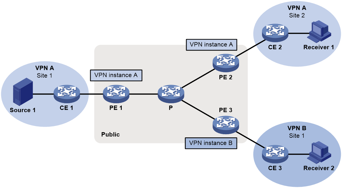
As shown in Figure 1, VPN A contains Site 1 and Site 3, and VPN B contains Site 2 and Site 4.
Figure 1 Typical network diagram for multicast VPN
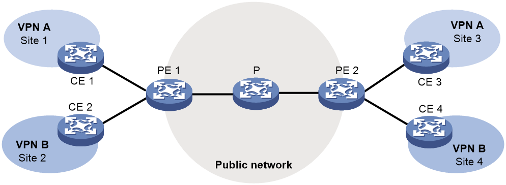
VPN multicast traffic between the PEs and the CEs is transmitted on a per-VPN-instance basis. The public network multicast traffic between the PEs and the P device is transmitted through the public network. Multicast VPN provides independent multicast services for the public network, VPN A, and VPN B.
For more information about CEs, PEs and Ps, see MPLS Configuration Guide.
MVPN scheme
MVPN is used to implement multicast VPN. MVPN only requires the PEs to support multiple VPN instances and the public network provided by the service provider to support multicast. There is no need to upgrade CEs and Ps or change their PIM configurations. The MVPN scheme is transparent to CEs and Ps.
MVPN supports the following modes: MDT, RSVP-TE, mLDP, and BIER.
Basic concepts in MDT-based MVPN
This section introduces the following basic concepts in MDT-based MVPN:
· MVPN—An MVPN logically defines the transmission boundary of the multicast traffic of a VPN over the public network. It also physically identifies all the PEs that support that VPN instance on the public network. Different VPN instances correspond to different MVPNs.
· Multicast distribution tree (MDT)—An MDT is a multicast distribution tree constructed by all PEs in the same VPN. MDT includes default MDT and data MDT.
· Multicast tunnel (MT)—An MT is a tunnel that interconnects all PEs in an MVPN. The local PE encapsulates a VPN multicast packet into a public network multicast packet and forwards it through the MT over the public network. The remote PE decapsulates the public network multicast packet to get the original VPN multicast packet.
· Multicast tunnel interface (MTI)—An MTI is the entrance or exit of an MT, equivalent to an entrance or exit of an MVPN. MTIs are automatically created when the MVPN for the VPN instance is created. PEs use the MTI to access the MT. The local PE sends VPN data out of the MTI. The remote PEs receive the private data from their MTIs. An MTI runs the same PIM mode as the VPN instance to which the MTI belongs. PIM is enabled on MTIs when a minimum of one interface in the VPN instance is enabled with PIM. When PIM is disabled on all interfaces in the VPN instance, PIM is also disabled on MTIs.
· Default group—A default group is a unique multicast address assigned to each MVPN on the public network. It is the unique identifier of an MVPN on the public network and helps build the default MDT for an MVPN on the public network. A PE encapsulates a VPN multicast packet (a multicast protocol packet or a multicast data packet) into a public network multicast packet. The default group address is used as the public network multicast group.
· Default MDT—A default MDT uses a default group address as its group address. In a VPN, the default MDT is uniquely identified by the default group. A default MDT is automatically created after the default group is specified and will always exist on the public network, regardless of the presence of any multicast services on the public network or the VPN.
· Data group—An MVPN is assigned a unique data group for MDT switchover. The ingress PE selects a least used address from the data group range to encapsulate the VPN multicast packets when the multicast traffic of the VPN reaches or exceeds a threshold. Other PEs are notified to use the address to forward the multicast traffic for that VPN. This initiates the switchover to the data MDT.
· Data MDT—A data MDT is an MDT that uses a data group as it group address. At MDT switchover, PEs with downstream receivers join a data group to build a data MDT. The ingress PE forwards the encapsulated VPN multicast traffic along the data MDT over the public network.
How MDT-based MVPN works
For a VPN instance, multicast data transmission on the public network is transparent. The VPN data is exchanged between the MTIs of the local PE and the remote PE. This implements the seamless transmission of the VPN data over the public network. However, the multicast data transmission process (the MDT transmission process) over the public network is very complicated.
|
|
NOTE: The following types of PIM neighboring relationships exist in MVPN: · PE-P PIM neighboring relationship—Established between the public network interface on a PE and the peer interface on the P device over the link. · PE-PE PIM neighboring relationship—Established between PEs that are in the same VPN instance after they receive the PIM hello packets. · PE-CE PIM neighboring relationship—Established between a PE interface that is bound with the VPN instance and the peer interface on the CE over the link. |
Default MDT establishment
The multicast routing protocol running on the public network can be PIM-DM, PIM-SM or PIM-SSM. The process of creating a default MDT is different in these PIM modes.
Default MDT establishment in a PIM-DM network
Figure 2 Default MDT establishment in a PIM-DM network
As shown in Figure 2, PIM-DM is enabled on the network, and all the PEs support VPN instance A. The process of establishing a default MDT is as follows:
1. To establish PIM neighboring relationships with PE 2 and PE 3 through the MTI for VPN instance A, PE 1 does the following:
a. Encapsulates the PIM protocol packet of the private network into a public network multicast data packet. PE 1 does this by specifying the source address as the IP address of the MVPN source interface and the multicast group address as the default group address.
b. Sends the multicast data packet to the public network.
For other PEs that support VPN instance A as default group members, PE 1 of VPN instance A initiates a flood-prune process in the entire public network. A (11.1.1.1, 239.1.1.1) state entry is created on each device along the path on the public network. This forms an SPT with PE 1 as the root, and PE 2 and PE 3 as leaves.
2. At the same time, PE 2 and PE 3 separately initiate a similar flood-prune process.
Finally, three independent SPTs are established in the MVPN, constituting the default MDT in the PIM-DM network.
Default MDT establishment in a PIM-SM network
Figure 3 Default MDT establishment in a PIM-SM network

As shown in Figure 3, PIM-SM is enabled on the network, and all the PEs support VPN instance A. The process of establishing a default MDT is as follows:
1. PE 1 initiates a join to the public network RP by specifying the multicast group address as the default group address in the join message. A (*, 239.1.1.1) state entry is created on each device along the path on the public network.
2. At the same time, PE 2 and PE 3 separately initiate a similar join process.
Finally, an RPT is established in the MVPN, with the public network RP as the root and PE 1, PE 2, and PE 3 as leaves.
3. To establish PIM neighboring relationships with PE 2 and PE 3 through the MTI for VPN instance A, PE 1 does the following:
a. Encapsulates the PIM protocol packet of the private network into a public network multicast data packet. PE 1 does this by specifying the source address as the IP address of the MVPN source interface and the multicast group address as the default group address.
b. Sends the multicast data packet to the public network.
The public network interface of PE 1 registers the multicast source with the public network RP, and the public network RP initiates a join to PE 1. A (11.1.1.1, 239.1.1.1) state entry is created on each device along the path on the public network.
4. At the same time, PE 2 and PE 3 separately initiate a similar register process.
Finally, three SPTs between the PEs and the RP are established in the MVPN.
In the PIM-SM network, the RPT, or the (*, 239.1.1.1) tree, and the three independent SPTs constitute the default MDT.
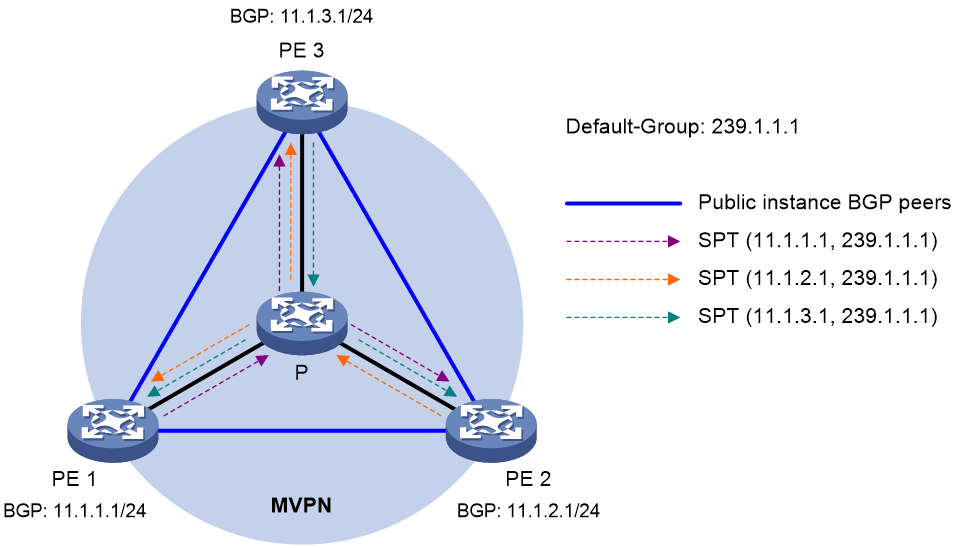
Default MDT establishment in a PIM-SSM network
Figure 4 Default MDT establishment in a PIM-SSM network

As shown in Figure 4, PIM-SSM runs on the network, and all the PEs support VPN instance A. The process of establishing a default MDT is as follows:
1. PE 1, PE 2, and PE 3 exchange MDT route information (including BGP interface address and the default group address) through BGP.
2. PE 1 sends a subscribe message to PE 2 and PE 3. Each device on the public network creates an (S, G) entry. An SPT is established in the MVPN with PE 1 as the root and PE 2 and PE 3 as the leaves.
At the same time, PE 2 and PE 3 separately initiate a similar process, and establish an SPT with itself as the root and the other PEs as the leaves.
3. The three independent SPTs constitute the default MDT in the PIM-SSM network.
In PIM-SSM, the term "subscribe message" refers to a join message.
Default MDT characteristics
No matter which PIM mode is running on the public network, the default MDT has the following characteristics:
· All PEs that support the same VPN instance join the default MDT.
Default MDT-based delivery
After the default MDT is established, the multicast source forwards the VPN multicast data to the receivers in each site along the default MDT. The VPN multicast packets are encapsulated into public network multicast packets on the local PE, and transmitted along the default MDT. Then, they are decapsulated on the remote PE and transmitted in that VPN site.
VPN multicast data packets are forwarded across the public network differently in the following circumstances:
· If PIM-DM or PIM-SSM is running in the VPN, the multicast source forwards multicast data packets to the receivers along the VPN SPT across the public network.
· When PIM-SM is running in the VPN:
¡ Before the RPT-to-SPT switchover, if the multicast source and the VPN RP are in different sites, the VPN multicast data packets travel to the VPN RP along the VPN SPT across the public network. If the VPN RP and the receivers are in different sites, the VPN multicast data packets travel to the receivers along the VPN RPT over the public network.
¡ After the RPT-to-SPT switchover, if the multicast source and the receivers are in different sites, the VPN multicast data packets travel to the receivers along the VPN SPT across the public network.
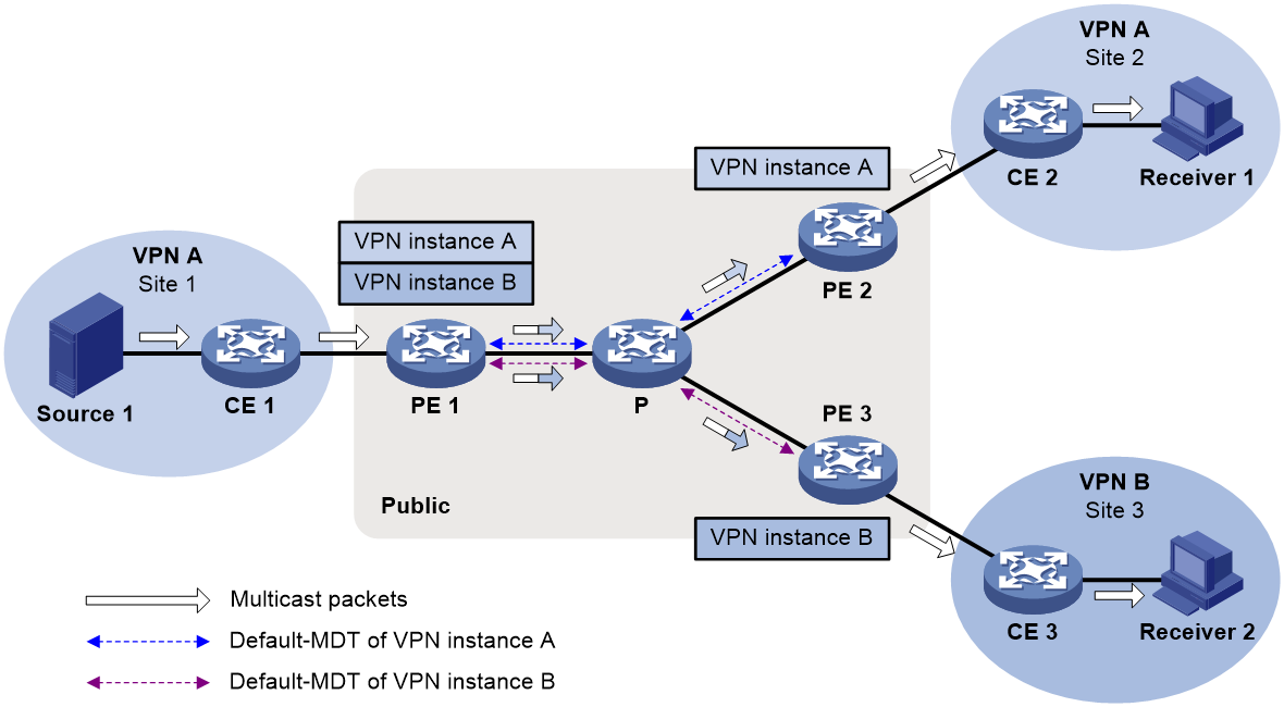
The following example explains how multicast data packets are delivered based on the default MDT when PIM-DM is running in both the public network and the VPN network.
As shown in Figure 5:
· PIM-DM is running in both the public network and the VPN sites.
· Receiver of the VPN multicast group G (225.1.1.1) in Site 2 is attached to CE 2.
· Source in Site 1 sends multicast data to multicast group (G).
· The default group address used to forward public network multicast data is 239.1.1.1.
Figure 5 Multicast data packet delivery
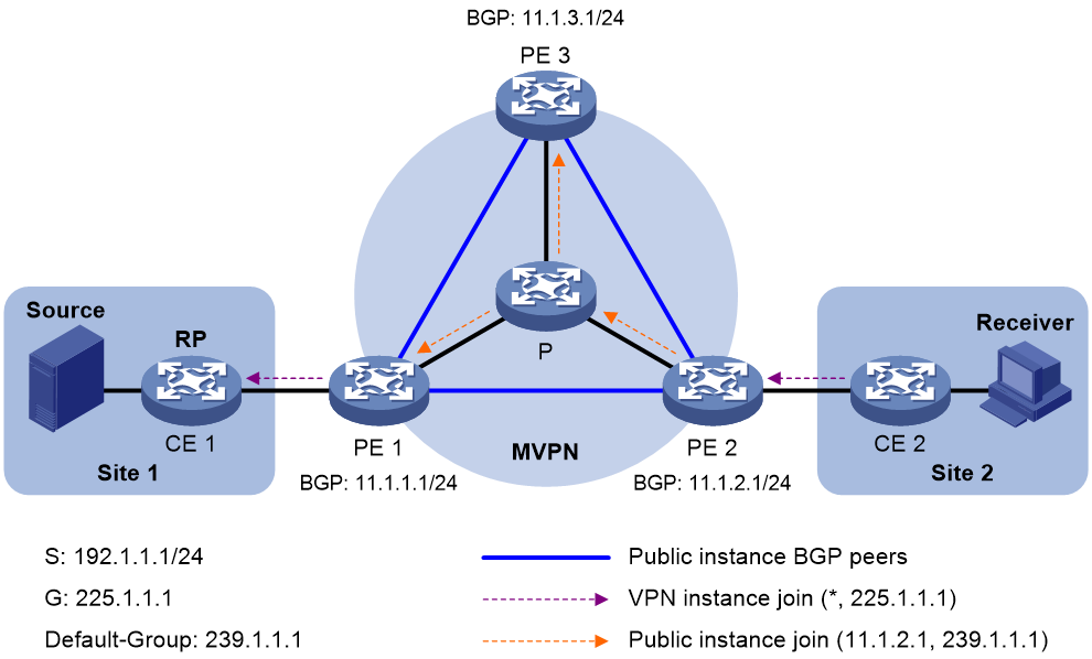
A VPN multicast data packet is delivered across the public network as follows:
1. Source sends a VPN multicast data packet (192.1.1.1, 225.1.1.1) to CE 1.
2. CE 1 forwards the VPN multicast data packet along an SPT to PE 1, and the VPN instance on PE 1 examines the MVRF.
If the outgoing interface list of the forwarding entry contains an MTI, PE 1 processes the VPN multicast data packet as described in step 3. The VPN instance on PE 1 considers the VPN multicast data packet to have been sent out of the MTI, because step 3 is transparent to it.
3. PE 1 encapsulates the VPN multicast data packet into a public network multicast packet (11.1.2.1, 239.1.1.1) by using the GRE method. The source IP address of the packet is the MVPN source interface 11.1.1.1, and the destination address is the default group address 239.1.1.1. PE 1 then forwards it to the public network.
4. The default MDT forwards the multicast data packet (11.1.2.1, 239.1.1.1) to the public network instance on all the PEs. After receiving this packet, every PE decapsulates it to get the original VPN multicast data packet, and passes it to the corresponding VPN instance. If a PE has a downstream interface for an SPT, it forwards the VPN multicast packet down the SPT. Otherwise, it discards the packet.
By now, the process of transmitting a VPN multicast data packet across the public network is completed.
MDT switchover
Switching from default MDT to data MDT
When a multicast packet of a VPN is transmitted through the default MDT on the public network, the packet is forwarded to all PEs that support that VPN instance. This occurs whether or not any active receivers exist in the attached sites. When the rate of the multicast traffic of that VPN is high, multicast data might get flooded on the public network. This increases the bandwidth use and brings extra burden on the PEs.
To optimize multicast transmission of large VPN multicast traffic that enters the public network, the MVPN solution introduces a dedicated data MDT. A data MDT is built between the PEs that connect VPN multicast receivers and multicast sources. When specific network criteria are met, the device switches over from the default MDT to the data MDT to forward VPN multicast traffic to receivers.
The device initiates a switchover of the default MDT to the data MDT as follows:
1. The source-side PE (PE 1, for example) periodically examines the forwarding rate of the VPN multicast traffic. The PE initiates a switchover of the default MDT to the data MDT only when the following criteria are both met:
¡ The VPN multicast data has passed the ACL rule filtering for MDT switchover.
¡ The traffic rate of the VPN multicast stream has exceeded the switchover threshold and stayed higher than the threshold for a certain length of time.
2. PE 1 selects a least-used address from the data group range. Then, it sends an MDT switchover message to all the other PEs down the default MDT. This message contains the VPN multicast source address, the VPN multicast group address, and the data group address.
3. Each PE that receives this message examines whether it interfaces with a VPN that has receivers of that VPN multicast stream.
If so, it joins the data MDT rooted at PE 1. Otherwise, it caches the message and will join the data MDT when it has attached receivers.
4. After sending the MDT switchover message, PE 1 starts the data-delay timer. When the timer expires, PE 1 uses the default group address to encapsulate the VPN multicast data. The multicast data is then forwarded down the data MDT.
5. After the multicast traffic is switched over from the default MDT to the data MDT, PE 1 continues sending MDT switchover messages periodically. Subsequent PEs with attached receivers can then join the data MDT. When a downstream PE no longer has active receivers attached to it, it leaves the data MDT.
For a given VPN instance, the default MDT and the data MDT are both forwarding tunnels in the same MVPN. A default MDT is uniquely identified by a default group address, and a data MDT is uniquely identified by a data group address. Each default group is uniquely associated with a data group range.
Backward switching from data MDT to default MDT
After the VPN multicast traffic is switched over to the data MDT, the multicast traffic conditions might change and no longer meet the switchover criterion. In this case, PE 1, as in the preceding example, initiates a backward MDT switchover process when any of the following criteria are met:
· The traffic rate of the VPN multicast data has dropped below the switchover threshold. In addition, the traffic rate has stayed lower than the threshold for a certain length of time (known as the data hold-down period).
· The associated data group range is changed, and the data group address for encapsulating the VPN multicast data is out of the new address range.
· The ACL rule for controlling the switchover from the default MDT to the data MDT has changed, and the VPN multicast data fails to pass the new ACL rule.
Inter-AS MDT-based MVPN
In an inter-AS VPN networking scenario, VPN sites are located in multiple ASs. These sites must be interconnected. Inter-AS VPN provides the following solutions:
· VRF-to-VRF connections between ASBRs—This solution is also called inter-AS option A.
· EBGP redistribution of labeled VPN-IPv4 routes between ASBRs—ASBRs advertise VPN-IPv4 routes to each other through MP-EBGP. This solution is also called inter-AS option B.
· Multihop EBGP redistribution of labeled VPN-IPv4 routes between PE devices—PEs advertise VPN-IPv4 routes to each other through MP-EBGP. This solution is also called inter-AS option C.
For more information about the three inter-AS VPN solutions, see MPLS L3VPN configuration in MPLS Configuration Guide.
Based on these solutions, there are three ways to implement inter-AS MDT-based MVPN:
· Inter-AS option A MDT-based MVPN.
· Inter-AS option B MDT-based MVPN.
· Inter-AS option C MDT-based MVPN.
Inter-AS option A MDT-based MVPN
As shown in Figure 6:
· Two VPN instances are in AS 1 and AS 2.
· PE 3 and PE 4 are ASBRs for AS 1 and AS 2, respectively.
· PE 3 and PE 4 are interconnected through their respective VPN instance and treat each other as a CE.
Figure 6 Inter-AS option A MDT-based MVPN
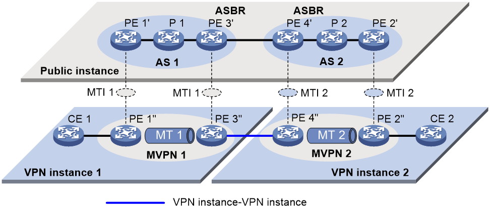
To implement inter-AS option A MDT-based MVPN, a separate MVPN must be created in each AS. Multicast data is transmitted between the VPNs in different ASs through the MVPNs.
Multicast packets of VPN instance 1 are delivered as follows:
1. CE 1 forwards the multicast packet of VPN instance 1 to PE 1.
2. PE 1 encapsulates the multicast packet into a public network packet and forwards it to PE 3 through the MTI interface in MVPN 1.
3. PE 3 considers PE 4 as a CE of VPN instance 1, so PE 3 forwards the multicast packet to PE 4.
4. PE 4 considers PE 3 as a CE of VPN instance 2, so it forwards the multicast packet to PE 2 through the MTI interface in MVPN 2 on the public network.
5. PE 2 forwards the multicast packet to CE 2.
Multicast packets of VPN 2 are delivered in the same way.
Because only VPN multicast data is forwarded between ASBRs, different PIM modes can run within different ASs. However, the same PIM mode must run on all interfaces that belong to the same VPN (including interfaces with VPN bindings on ASBRs).
Inter-AS option B MDT-based MVPN
In inter-AS option B MDT-based MVPN, RPF vector and BGP connector are introduced:
· RPF vector—Attribute encapsulated in a PIM join message. It is the next hop of BGP MDT route from the local PE to the remote PE. Typically, it is the ASBR in the local AS.
When a device receives the join message with the RPF vector, it first checks whether the RPF vector is its own IP address. If so, the device removes the RPF vector, and sends the message to its upstream neighbor according to the route to the remote PE. Otherwise, it keeps the RPF vector, looks up the route to the RPF vector, and sends the message to the next hop of the route. In this way, the PIM message can be forwarded across the ASs and an MDT is established.
· BGP connector—Attribute shared by BGP peers when they exchange VPNv4 routes. It is the IP address of the remote PE.
The local PE fills the upstream neighbor address field with the BGP connector in a join message. This ensures that the message can pass the RPF check on the remote PE after it travels along the MT.
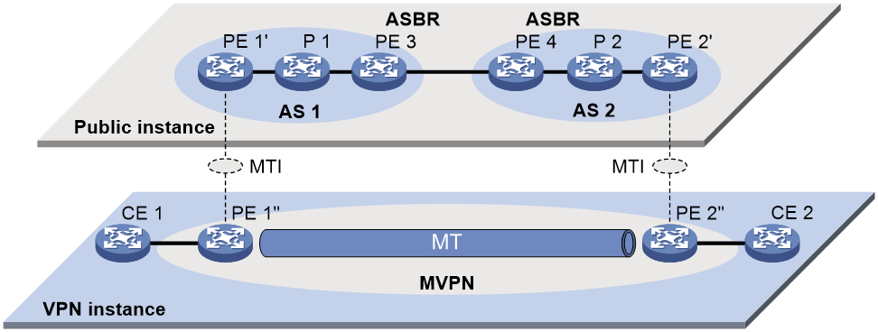
As shown in Figure 7:
· A VPN network involves AS 1 and AS 2.
· PE 3 and PE 4 are the ASBRs for AS 1 and AS 2, respectively.
· PE 3 and PE 4 are interconnected through MP-EBGP and treat each other as a P device.
· PE 3 and PE 4 advertise VPN-IPv4 routes to each other through MP-EBGP.
· An MT is established between PE 1 and PE 2 for delivering VPN multicast traffic across the ASs.
Figure 7 Inter-AS option B MDT-based MVPN

The establishment of the MVPN on the public network is as follows:
1. PE 1 originates a PIM join message to join the SPT rooted at PE 2. In the join message, the upstream neighbor address is the IP address of PE 2 (the BGP connector). The RPF vector attribute is the IP address of PE 3. PE 1 encapsulates the join message as a public network packet and forwards it through the MTI.
2. P 1 determines that the RPF vector is not an IP address of its own. It looks up the routing table for a route to PE 3, and forwards the packet to PE 3.
3. PE 3 removes the RPF vector because the RPF vector is its own IP address. It fails to find a BGP MDT route to PE 2, so it encapsulates a new RPF vector (IP address of PE 4) in the packet and forwards it to PE 4.
4. PE 4 removes the RPF vector because the RPF vector is its own IP address. It has a local route to PE 2, so it forwards the packet to P 2, which is the next hop of the route to PE 2.
5. P 2 sends the packet to PE 2.
6. PE 2 receives the packet on the MTI and decapsulates the packet. The receiving interface is the RPF interface of the RPF route back to PE 1 for the join message, and the join message passes the RPF check. The SPT from PE 1 to PE 2 is established.
When PE 1 joins the SPT rooted at PE 1, PE 2 also initiates a join process to the SPT rooted at PE 1. A MDT is established when the two SPTs are finished.
Inter-AS option C MDT-based MVPN
As shown in Figure 8:
· A VPN instance spans AS 1 and AS 2.
· PE 3 and PE 4 are the ASBRs for AS 1 and AS 2, respectively.
· PE 3 and PE 4 are interconnected through MP-EBGP and treat each other as a P device.
· PEs in different ASs establish a multihop MP-EBGP session to advertise VPN-IPv4 routes to each other.
Figure 8 Inter-AS option C MDT-based MVPN
To implement inter-AS option C MDT-based MVPN, only one MVPN needs to be created for the two ASs. Multicast data is transmitted between the two ASs through the MVPN.
Multicast packets are delivered as follows:
1. CE 1 forwards the VPN instance multicast packet to PE 1.
2. PE 1 encapsulates the multicast packet into a public network multicast packet and forwards it to PE 3 through the MTI interface on the public network.
3. PE 3 and PE 4 are interconnected through MP-EBGP, so PE 3 forwards the public network multicast packet to PE 4 along the VPN IPv4 route.
4. The public network multicast packet arrives at the MTI interface of PE 2 in AS 2. PE 2 decapsulates the public network multicast packet and forwards the VPN multicast packet to CE 2.
Basic concepts in RSVP-TE-based MVPN
This section introduces the following concepts in RSVP-TE-based MVPN:
· MVPN—An MVPN logically defines the transmission boundary of the multicast traffic of a VPN over the public network. It also physically identifies all the PEs that support that VPN instance on the public network. Different VPN instances correspond to different MVPNs. All PEs in an MVPN are MVPN peers.
· Inclusive tunnel—Transmits all multicast packets (including multicast protocol packets and multicast data packets of all multicast groups) for an MVPN. Only one inclusive tunnel can be established between two PEs in the MVPN. A PE encapsulates multicast data packets and PIM BSMs of an MVPN into public network multicast data packets and sends them over the public network through the inclusive tunnel.
· Selective tunnel—Transmits multicast packets of one or more multicast groups for an MVPN. Multiple selective tunnels can be established between two PEs in the MVPN.
How RSVP-TE-based MVPN works
RSVP-TE-based MVPN operation
Packet transmission on the public network is transparent for a VPN instance. Each two PEs establish IBGP neighbor relationship and use BGP to advertise routing information for MVPN. The following types of routes are used to create RSVP-TE tunnels for an MVPN:
· Intra-AS I-PMSI A-D route—PEs use this type of route to establish inclusive tunnels.
· S-PMSI A-D route—The multicast source-side PE sends this type of route to receiver-side PEs for tunnel switchover when selective tunnel creation is enabled and the tunnel creation criterion is met.
· Leaf A-D route—A receiver-side PE that has attached receivers replies with a Leaf A-D route when it receives an S-PMSI A-D route from the multicast source-side PE. RSVP-TE creates selective tunnels between receiver-side PEs and the multicast-side PE based on the neighbor information contained in Leaf A-D routes.
· Source Active A-D route—The multicast source-side PE sends this type of route to receiver-side PEs to advertise the location of the multicast source.
· C-multicast route—After receiving the Source Active A-D route from the multicast source-side PE, a receiver-side PE replies with a C-Multicast route to request the multicast source-side PE to send multicast data.
Multicast packets of a VPN instance are seamlessly transmitted from a CE to the inclusive tunnel on the PE based on the PIM routing table. These packets are then transmitted to the remote PE through the inclusive tunnel. After receiving the packets, the remote PE decapsulates the packets to get the original private packets. The multicast source-side PE creates selective tunnels when multicast traffic that meets the tunnel switchover criterion arrives.
Inclusive tunnel establishment
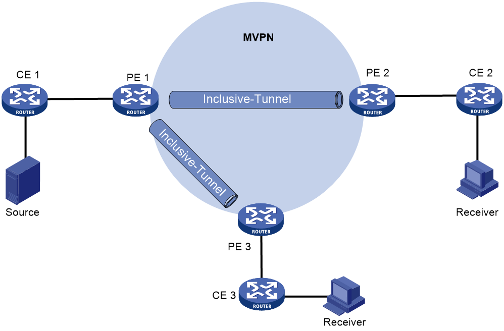
As shown in Figure 9, the private network runs PIM, and the public network uses MPLS backbone. The inclusive tunnels are established as follows:
1. PE 1, PE 2, and PE 3 mutually establish IBGP neighbor relationship and exchange routing information to get the public network address of each PE.
2. PE 1 (source of the tunnel) sends an Intra-AS I-PMSI A-D route to PE 2 and PE 3 (destination of the tunnel) to advertise the inclusive tunnel information.
3. PE 2 and PE 3 each establish an inclusive tunnel with PE 1. The inclusive tunnel on the public network does not rely on PIM running on the private network.
Figure 9 Inclusive tunnel establishment

Selective tunnel establishment and tunnel switchover
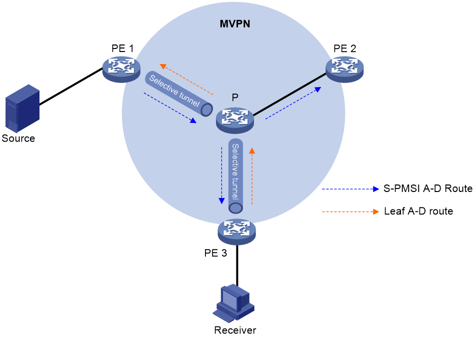
As shown in Figure 10, selective tunnels are established and switched as follows:
1. After multicast source-side PE 1 receives a multicast packet of the (S, G) entry that meets the tunnel switchover criterion, it sends an S-PMSI A-D route to PE 2 and PE 3.
2. PE 2 does not send a response because it has no receivers of the (S,G) entry attached.
3. PE 3 replies with a Leaf A-D route because it is attached to a receiver of the entry.
4. PE 1 and PE 3 establish a selective tunnel.
5. Subsequent multicast packets of the (S,G) entry that enters the public network from PE 1 are switched over to the selective tunnel from the inclusive tunnel.
Figure 10 Selective tunnel establishment
Basic concepts in mLDP-based MVPN
Basic concepts in mLDP-based MVPN are the same as those in RSVP-TE-based MVPN. For more information about basic concepts in RSVP-TE-based MVPN, see "Basic concepts in RSVP-TE-based MVPN."
How mLDP-based MVPN works
mLDP-based MVPN operation
The operation of mLDP-based MVPN is similar to that of RSVP-TE-based MVPN. They differ in the direction in which the public network P2MP tunnel is created.
· RSVP-TE-based MVPN—Starting from the ingress PE, the upstream devices use RSVP to establish RSVP-TE P2MP tunnels with downstream devices. In this mode, the ingress PE needs to know the IP address of the egress PE.
· mLDP-based MVPN—Starting from the egress PE, the downstream devices use LDP to establish mLDP P2MP tunnels with downstream devices. In this mode, the egress PE needs to the IP address of the ingress PE.
For more information about the RSVP-TE-based MVPN operation, see "RSVP-TE-based MVPN operation."
Inclusive tunnel establishment
As shown in Figure 11, the private network runs PIM, and the public network uses MPLS backbone. The inclusive tunnels are established as follows:
1. PE 1, PE 2, and PE 3 mutually establish IBGP neighbor relationship and exchange routing information.
2. PE 1 (the source of the tunnel) advertises the inclusive tunnel information to PE 2 and PE 3.
3. PE 2 and PE 3 each uses LDP to establish an inclusive mLDP tunnel with PE 1. The inclusive tunnel on the public network does not rely on PIM running on the private network.
Figure 11 Establishment of the inclusive tunnel
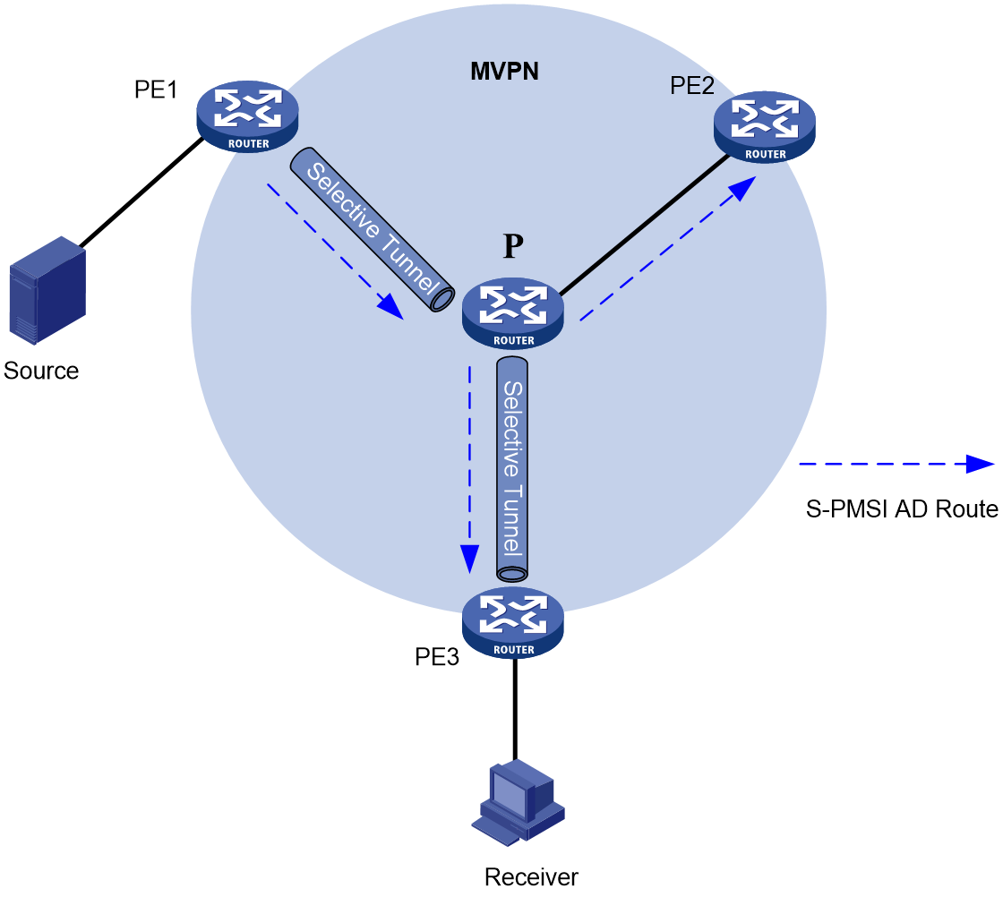
Selective tunnel establishment and tunnel switchover
mLDP-based MVPN supports switchover from the inclusive tunnel to selective tunnels to off-load traffic for specific (S, G) entries from the inclusive tunnel. An MVPN can have multiple selective tunnels.
As shown in Figure 12, the process of selective tunnel creation and the tunnel switchover is as follows:
1. Upon receiving a multicast packet for the (S, G) entry that meets the tunnel switchover criterion, the multicast source-side PE 1 sends an S-PMSI A-D route to PE 2 and PE 3.
2. PE 2 does not respond to the route because it has no receivers of the (S,G) entry attached.
3. PE 3 which has a receiver attached uses LDP to establish a selective tunnel with PE 1.
4. Subsequent multicast packets for the (S,G) entry are transmitted over the selective tunnel instead of the inclusive tunnel on the public network.
Figure 12 Selective tunnel establishment and tunnel switchover
Inter-AS mLDP-based MVPN
In an inter-AS VPN networking scenario, VPN sites are located in multiple ASs. These sites must be interconnected. Inter-AS VPN provides the following solutions:
· VRF-to-VRF connections between ASBRs—This solution is also called inter-AS option A.
· EBGP redistribution of labeled VPN-IPv4 routes between ASBRs—ASBRs advertise VPN-IPv4 routes to each other through MP-EBGP. This solution is also called inter-AS option B.
· Multihop EBGP redistribution of labeled VPN-IPv4 routes between PE devices—PEs advertise VPN-IPv4 routes to each other through MP-EBGP. This solution is also called inter-AS option C.
For more information about the three inter-AS VPN solutions, see MPLS L3VPN configuration in MPLS Configuration Guide.
Inter-AS option A mLDP-based MVPN
As shown in Figure 13:
· A VPN instance spans AS 100 and AS 200.
· PE 3 and PE 4 are ASBRs for AS 100 and AS 200, respectively.
· PE 3 and PE 4 are interconnected through their respective VPN instance and treat each other as a CE.
Figure 13 Inter-AS option A mLDP-based MVPN
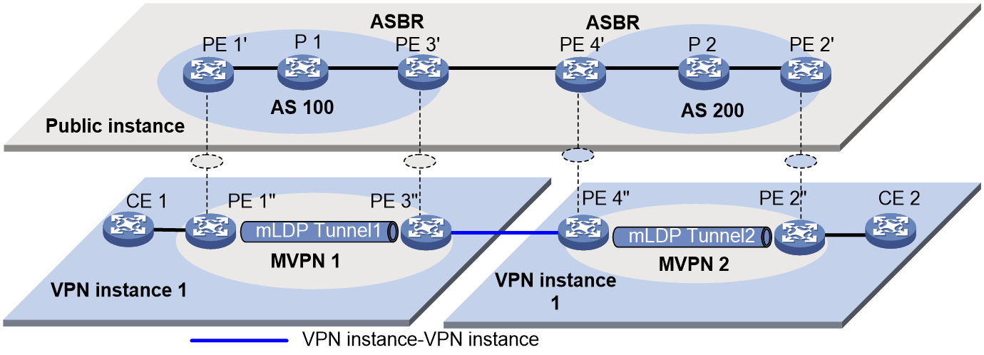
To implement inter-AS option A mLDP-based MVPN, a separate MVPN must be created in each AS. Multicast data of the VPN instance is transmitted across the ASs through the separate MVPNs in each AS.
Multicast packets of the VPN instance are delivered as follows:
1. CE 1 forwards a multicast packet of VPN instance 1 to PE 1.
2. PE 1 encapsulates the multicast packet into an MPLS packet and forwards it to PE 3 through mLDP tunnel 1.
3. PE 3 considers PE 4 as a CE of MVPN 1, so PE 3 decapsulates the MPLS packet and forwards the multicast packet to PE 4.
4. PE 4 considers PE 2 as a CE of MVPN 2, so PE 4 encapsulates the multicast packet into an MPLS packet and then forwards the packet to PE 2 through mLDP tunnel 2.
5. PE 2 decapsulates the MPLS packet and then forwards the multicast packet to CE 2.
In inter-AS option A, PEs in different ASs cannot advertise Source Active A-D routes to each other. Therefore, you must configure MSDP or Anycast-RP between RPs to allow Source Active A-D routes to be advertised across ASs.
Inter-AS option B mLDP-based MVPN
As shown in Figure 14:
· A VPN instance spans AS 100 and AS 200.
· PE 3 and PE 4 are the ASBRs for AS 100 and AS 200, respectively.
· PE 3 and PE 4 are interconnected through MP-EBGP and treat each other as a P device.
· PE 3 and PE 4 advertise VPN-IPv4 routes to each other through MP-EBGP.
Figure 14 Inter-AS option B mLDP-based MVPN
To implement inter-AS option B mLDP-based MVPN, only one MVPN needs to be established across all ASs. VPN multicast data is transmitted across the ASs through this MVPN.
Multicast packets of the VPN instance are transmitted as follows:
1. Upon receiving a multicast packet of a multicast group in the VPN instance, CE 1 advertises the RP information for this group to PE 1 as follows:
¡ If the RP is PE 1, CE 1 directly sends a register message to PE 1 to advertise the RP information.
¡ If the RP is CE 1 or CE 2, CE 1 advertises the RP information to PE 1 through MSDP or Anycast-RP depending on the actual configuration.
2. PE 1 sends a Source Active A-D route to PE 3, PE 4, and PE 2 through BGP.
3. PE 2 sends a C-multicast route to join the multicast group if it has a receiver attached. The C-multicast route will be advertised to PE 4, PE 3, and PE 1 through BGP.
4. Upon receiving the C-multicast route, PE 1 encapsulates the multicast packet into an MPLS packet and then sends the packet to PE 2 through the mLDP tunnel.
5. PE 2 decapsulates the MPLS packet and then sends the multicast packet to CE 2.
Inter-AS option C mLDP-based MVPN
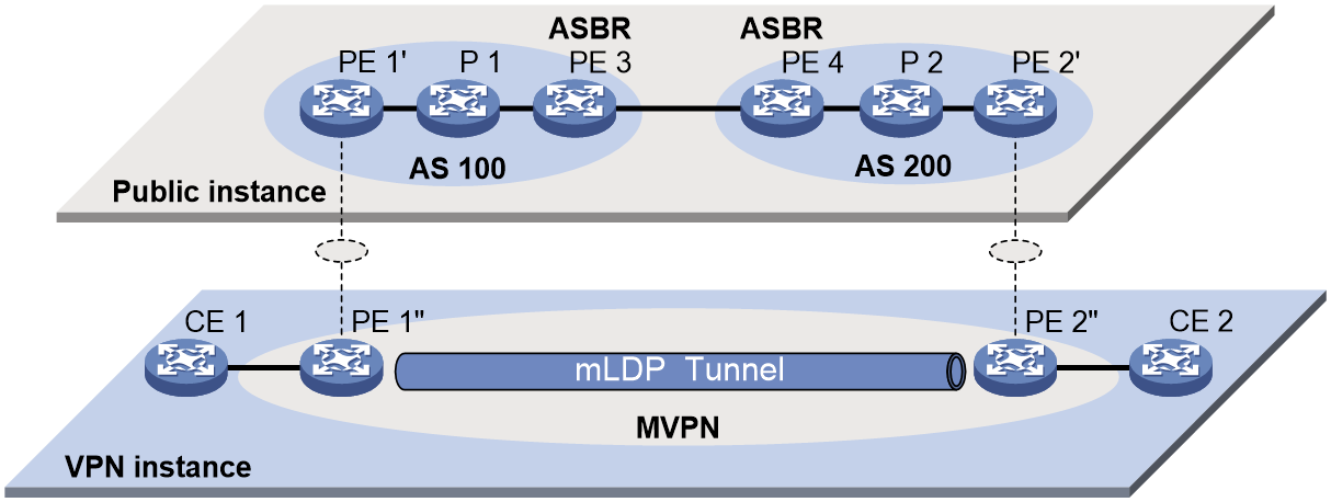
As shown in Figure 15:
· A VPN instance spans AS 100 and AS 200.
· PE 3 and PE 4 are the ASBRs for AS 100 and AS 200, respectively.
· PE 3 and PE 4 are interconnected through MP-EBGP and treat each other as a P device.
· PEs in different ASs establish a multihop MP-EBGP session to advertise VPN-IPv4 routes to each other.
Figure 15 Inter-AS option C mLDP-based MVPN

To implement inter-AS option C mLDP-based MVPN, only one MVPN needs to be created cross all ASs. Multicast data is transmitted across the ASs through this MVPN.
Multicast packets of the VPN instance are delivered as follows:
1. Upon receiving a multicast packet of a multicast group in the VPN instance, CE 1 advertises the RP information for this group to PE 1 as follows:
¡ If the RP is PE 1, CE 1 directly sends a register message to PE 1 to advertise the RP information.
¡ If the RP is CE 1 or CE 2, CE 1 advertises the RP information to PE 1 through MSDP or Anycast-RP depending on the actual configuration.
2. PE 1 sends a source-active A-D route to PE 2 through BGP.
3. PE 2 sends a C-multicast route to join the multicast group if it has a receiver attached. The C-multicast route will be advertised to PE 1 through BGP.
4. PE 1 encapsulates the multicast packet into an MPLS packet and then sends the packet to PE 2 through the mLDP tunnel.
5. PE 2 decapsulates the MPLS packet and then sends the multicast packet to CE 2.
Basic concepts in BIER
BIER domain and BIER sub-domain
All BFRs in a network are referred to as a BIER domain. A BIER domain can contain one or more sub-domains. Each sub-domain is identified by a sub-domain ID. All BFIRs and BFERs in a sub-domain are called BIER edge devices.
BFR ID
A BFR ID uniquely identifies a BIER edge device in a sub-domain. A transit BFR does not need to have a BFR ID.
BFR prefix
A BFR prefix is an IP address that uniquely identifies a BFR in a sub-domain. A BFR prefix must be routable in the sub-domain and can only be the IP address of a loopack interface.
Bit string
A bit string represents a set of BIER edge devices, with each bit corresponding to a BFR ID, starting from the rightmost position. The bit string length (BSL) refers to the number of bits in the bit string. A bit string with three bits can identify a maximum of three BIER edge devices. The BIER edge device with BFR ID is represented as 001.
Set identifier
When the number of BFR IDs is greater than the number of bits in the bit string, the bit string needs to be divided into sets identified by set identifiers (SI). For example, if the maximum BFR ID is 10 in a BIER sub-domain and the bit string length is 4, the bit string needs to be divided into three SIs (SI 0, SI 1, and SI 2). The maximum SI is (Maximum BFR ID–1)/BSL rounded down to the nearest integer.
Bit Index Routing Table
The Bit Index Routing Table (BIRT) is generated based on the BIER information ((sub-domain, BSL, and BFR ID) and routing informtion carried by IGP. The BIRT is used to guide the forwarding of BIER packets in a BIER sub-domain.
Forwarding Bit Mask
The Forwarding Bit Mask (F-BM) represents a set of edge nodes in a BIER sub-domain that are reachable through a BFR neighbor (BFR-NBR). The bit mask is obtained by taking the logical OR of the bit strings of all reachable edge nodes.
Bit Index Forwarding Table
The Bit Index Forwarding Table (BIFT) can guide the per-hop forwarding of multicast traffic in a BIER sub-domain.
The BIFT is used to map from the BFR ID of a BFER to the corresponding F-BM and BFR-NBR. Multiple BIFT can exist on a BFR. Each BIFT is identified by a combination of the BSL, SD, and SI).
How BIER-based MVPN works
BIER-based MVPN operation
BIER-based MVPN encapsulates multicast traffic in a private network and sends it to other nodes in the BIER sub domain.
The multicast source-side PE sends BGP MVPN routes to receiver-side PEs for establishing BIER tunnels. This process is similar to that of RSVP-TE-based MVPN and mLDP-based MVPN except that the Intra-AS I-PMSI A-D route, S-PMSI A-D route, and Leaf A-D route carry BIER information, including BFR ID, Sub domain ID, and BFR prefix. After encapsulating the received private network multicast traffic with Bit String, the PE performs BIER forwarding for the traffic in the public network. For more information about BIER forwarding, see BIER Configuration Guide.
Similar to RSVP-TE-based MVPN and mLDP-based MVPN, in BIER-based MVPN mode, multicast packets of a VPN instance are seamlessly transmitted from a CE to the inclusive tunnel on the PE based on the PIM routing table. These packets are then transmitted to the remote PE through the inclusive tunnel. After receiving the packets, the remote PE decapsulates the packets to get the original private packets. The multicast source-side PE creates selective tunnels when multicast traffic that meets the tunnel switchover criterion arrives.
Inclusive tunnel establishment
As shown in Figure 16, the private network runs PIM, and the public network uses BIER. The inclusive tunnels are established as follows:
1. PE 1 sends an Intra-AS I-PMSI A-D route to PE 2 and PE 3. The route contains the following information:
¡ Route Target—Controls route transmission and receiving. It is configured as the export target of PE 1.
¡ PMSI Tunnel attribute—Transmits tunnel information, where the value for the Tunnel Type field is the BIER tunnel, and the field contains BIER information including Sub domain ID, BFR ID, and BFR prefix for PE 1.
2. Upon receiving the Intra-AS I-PMSI A-D route, PE 2 and PE 3 identify whether the Route Target field matches the Import Target configured in the local VPN instance. If they match, the PEs accept the route and respond with a Leaf A-D route to PE 1. The route contains the following information:
¡ Route Target— Controls route transmission and receiving. It is configured as the export target of PE 2 or PE 3.
¡ PMSI Tunnel attribute—Transmits tunnel information, where the value for the Tunnel Type field is the BIER tunnel. This field contains information about the BFIRs and BFERs in the same sub domain as PE 1. The information is obtained by checking the BFR ID and BFR prefix configured in the local sub domain with an ID same as that in the Intra-AS I-PMSI A-D route sent by PE 1.
3. Upon receiving the Leaf A-D route, PE 1 identifies whether the Route Target field matches the Import Target configured in the local VPN instance. If they match, PE 1 accept the route and marks PE 2 and PE 3 as members of the MVPN. At the same time, PE 1 obtains the SI based on the BFR ID in the route and the value of the BSL in the BIER sub domain. Then PE 1 combines information about all leaf nodes and generates bit string for the (S, G) entry to establish an inclusive tunnel.
Figure 16 Inclusive tunnel establishment

Selective tunnel establishment and tunnel switchover
BIER-based MVPN supports switchover from the inclusive tunnel to selective tunnels to off-load traffic for specific (S, G) entries from the inclusive tunnel. An MVPN can have multiple selective tunnels.
As shown in Figure 17, the process of selective tunnel creation and the tunnel switchover is as follows:
1. PE 1 sends an S-PMSI A-D route to PE 2 and PE 3. The route contains the following information:
¡ Route Target—Controls route transmission and receiving. It is configured as the export target of PE 1.
¡ PMSI Tunnel attribute—Transmits tunnel information, where the value for the Tunnel Type field is the BIER tunnel, and the field contains BIER information including Sub domain ID, BFR ID, and BFR prefix for PE 1.
2. Upon receiving the S-PMSI A-D route, PE 2 and PE 3 identify whether the Route Target field matches the Import Target configured in the local VPN instance. If they match, the PEs accept the route and if a downstream receiver exists, the two PEs respond with a Leaf A-D route to PE 1. The route contains the following information:
¡ Route Target— Controls route transmission and receiving. It is configured as the export target of PE 2 or PE 3.
¡ PMSI Tunnel attribute—Transmits tunnel information, where the value for the Tunnel Type field is the BIER tunnel. This field contains information about the BFIRs and BFERs in the same sub domain as PE 1. The information is obtained by checking the BFR ID and BFR prefix configured in the local sub domain with an ID same as that in the Intra-AS I-PMSI A-D route sent by PE 1.
3. Upon receiving the Leaf A-D route, PE 1 identifies whether the Route Target field matches the Import Target configured in the local VPN instance. If they match, PE 1 accept the route and marks PE 2 and PE 3 as members of the MVPN. At the same time, PE 1 obtains the SI based on the BFR ID in the route and the value of the BSL in the BIER sub domain. Then PE 1 combines information about all leaf nodes and generates bit string for the (S, G) entry to establish a selective tunnel.
Figure 17 Selective tunnel establishment and tunnel switchover

Inter-AS BIER-based MVPN
In an inter-AS VPN networking scenario, VPN sites are located in multiple ASs. These sites must be interconnected. Inter-AS VPN provides the following solutions:
· VRF-to-VRF connections between ASBRs—This solution is also called inter-AS option A.
· Multihop EBGP redistribution of labeled VPN-IPv4 routes between PE devices—PEs advertise VPN-IPv4 routes to each other through MP-EBGP. This solution is also called inter-AS option C.
For more information about the three inter-AS VPN solutions, see MPLS L3VPN configuration in MPLS Configuration Guide.
Inter-AS option A BIER-based MVPN
As shown in Figure 18:
· A VPN instance spans AS 100 and AS 200.
· PE 3 and PE 4 are ASBRs for AS 100 and AS 200, respectively.
· PE 3 and PE 4 are interconnected through their respective VPN instance and treat each other as a CE.
Figure 18 Inter-AS option A BIER-based MVPN

To implement inter-AS option A mLDP-based MVPN, a separate MVPN must be created in each AS. Multicast data of the VPN instance is transmitted across the ASs through the separate MVPNs in each AS.
Multicast packets of the VPN instance are delivered as follows:
1. CE 1 forwards a multicast packet of VPN instance 1 to PE 1.
2. PE 1 encapsulates the multicast packet into an MPLS packet and forwards it to PE 3 through BIER tunnel 1.
3. PE 3 considers PE 4 as a CE of MVPN 1, so PE 3 decapsulates the MPLS packet and forwards the multicast packet to PE 4.
4. PE 4 considers PE 2 as a CE of MVPN 2, so PE 4 encapsulates the multicast packet into an MPLS packet and then forwards the packet to PE 2 through BIER tunnel 2.
5. PE 2 decapsulates the MPLS packet and then forwards the multicast packet to CE 2.
In inter-AS option A, PEs in different ASs cannot advertise Source Active A-D routes to each other. Therefore, you must configure MSDP or Anycast-RP between RPs to allow Source Active A-D routes to be advertised across ASs.
Inter-AS option C BIER-based MVPN
As shown in Figure 19:
· A VPN instance spans AS 100 and AS 200.
· PE 3 and PE 4 are the ASBRs for AS 100 and AS 200, respectively.
· PE 3 and PE 4 are interconnected through MP-EBGP and treat each other as a P device.
· PEs in different ASs establish a multihop MP-EBGP session to advertise VPN-IPv4 routes to each other.
Figure 19 Inter-AS option C BIER-based MVPN

To implement inter-AS option C mLDP-based MVPN, only one MVPN needs to be created cross all ASs. Multicast data is transmitted across the ASs through this MVPN.
Multicast packets of the VPN instance are delivered as follows:
1. Upon receiving a multicast packet of a multicast group in the VPN instance, CE 1 advertises the RP information for this group to PE 1 as follows:
¡ If the RP is PE 1, CE 1 directly sends a register message to PE 1 to advertise the RP information.
¡ If the RP is CE 1 or CE 2, CE 1 advertises the RP information to PE 1 through MSDP or Anycast-RP depending on the actual configuration.
2. PE 1 sends a source-active A-D route to PE 2 through BGP.
3. PE 2 sends a C-multicast route to join the multicast group if it has a receiver attached. The C-multicast route will be advertised to PE 1 through BGP.
4. PE 1 encapsulates the multicast packet into an MPLS packet and then sends the packet to PE 2 through the BIER tunnel.
5. PE 2 decapsulates the MPLS packet and then sends the multicast packet to CE 2.
MVPN extranet
MVPN extranet implements inter-VPN multicast traffic transmission. In MVPN extranet, the multicast source and receivers are in different VPNs. In actual application, the MVPN extranet solution ensures that the service provider in a VPN provides multicast services for users in other VPNs.
The following terms are used in the MVPN extranet solution:
· Source VPN instance—VPN instance to which the multicast source belongs.
· Receiver VPN instance—VPN instance to which the multicast receiver belongs.
· Source PE—PE directly connected to the multicast source.
· Receiver PE—PE directly connected to multicast receivers.
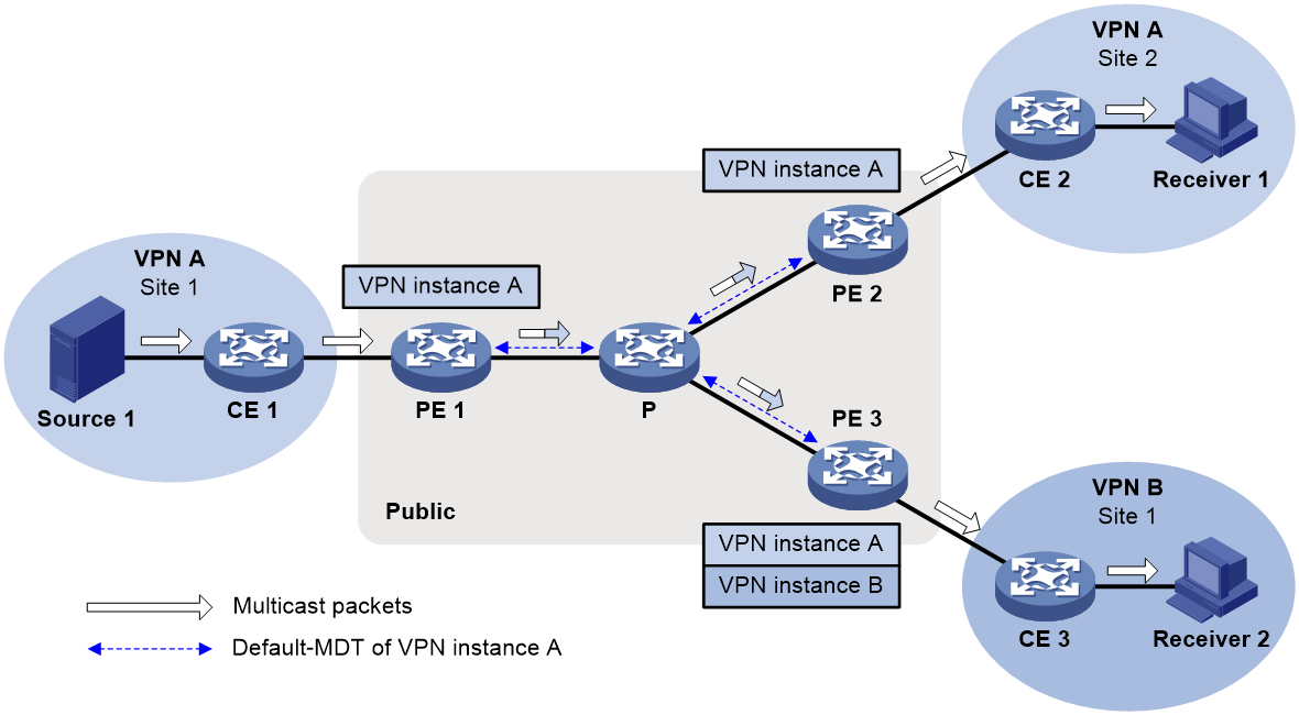
As shown in Figure 20, multicast source Source 1 is in Site 1 of VPN A. Receiver 1 and Receiver 2 are located in Site 2 of VPN A and Site 1 of VPN B, respectively. MVPN enables Receiver 1 to receive multicast data from Source 1, and MVPN extranet enables Receiver 2 to receive multicast data from Source 1.
The MVPN extranet solution can be implemented through the source-PE-based MVPN extranet option or the receiver-PE-based MVPN extranet option.
Source-PE-based MVPN extranet option
To use this option, create a receiver VPN instance on the source PE and specify a default group for this VPN instance. The default group for the receiver VPN instance must be the same as the default group specified on other PEs in this VPN instance.
This option is available only in MDT-based MVPN.
As shown in Figure 21, perform the following tasks:
1. For multicast traffic transmission from Site 1 to Site 2, configure MVPN for VPN A on PE 1 and PE 2.
2. For multicast traffic transmission from Site 1 to Site 3, create VPN B and configure MVPN for VPN B on PE 1.
3. Configure an MVPN extranet RPF selection policy for VPN B on PE 1.
Figure 21 Source-PE-based MVPN extranet option
When Receiver 2 in VPN B joins the multicast group that matches the policy, multicast packets from Source 1 are transmitted as follows:
1. PE 1 replicates and encapsulates the packets for VPN A and VPN B and forwards them.
2. The packets travel along default MDTs of VPN A and VPN B and arrive at PE 2 and PE 3.
3. PE 2 and PE 3 decapsulate and forward the packets to receivers.
Receiver-PE-based MVPN extranet option
To use this option, create a source VPN instance on the receiver PE and specifies a default group for this VPN instance. The default group for the source VPN instance must be the same as the default group specified on other PEs in this VPN instance.
This option is available in MDT-based MVPN, RSVP-TE-based MVPN, and mLDP-based MVPN. This example uses MDT-based MVPN.
As shown in Figure 22, configure PEs as follows:
1. For multicast traffic transmission from Site 1 to Site 2, configure MVPN for VPN A on PE 1 and PE 2.
2. For multicast traffic transmission from Site 1 to Site 3, create VPN A and configure MVPN for VPN A on PE 3.
3. Configure an MVPN extranet RPF selection policy for VPN B on PE 3.
Figure 22 Receiver-PE-based MVPN extranet option
When Receiver 2 in VPN B joins the multicast group that matches the RPF selection policy, multicast packets from Source 1 are encapsulated on PE 1 and transmitted along the default MDT.
· When the packets arrive at PE 2, PE 2 decapsulates the packets and forwards them to Receiver 1.
· When the packets arrive at PE 3, PE 3 decapsulates the packets and forwards them to Receiver 2 based on the MVPN extranet RPF selection policy.
M6VPE
Only mLDP-based M6VPE is supported in the current software version.
The multicast IPv6 VPN provider edge (M6VPE) feature enables PEs to transmit IPv6 multicast traffic of a VPN instance over the public network. Only the IPv4 network is available for the backbone network.
As shown in Figure 23, the public network runs IPv4 protocols, and sites of VPN instance VPN A run IPv6 multicast protocols. To transmit IPv6 multicast traffic between CE 1 and CE 2, configure M6VPE on the PEs.
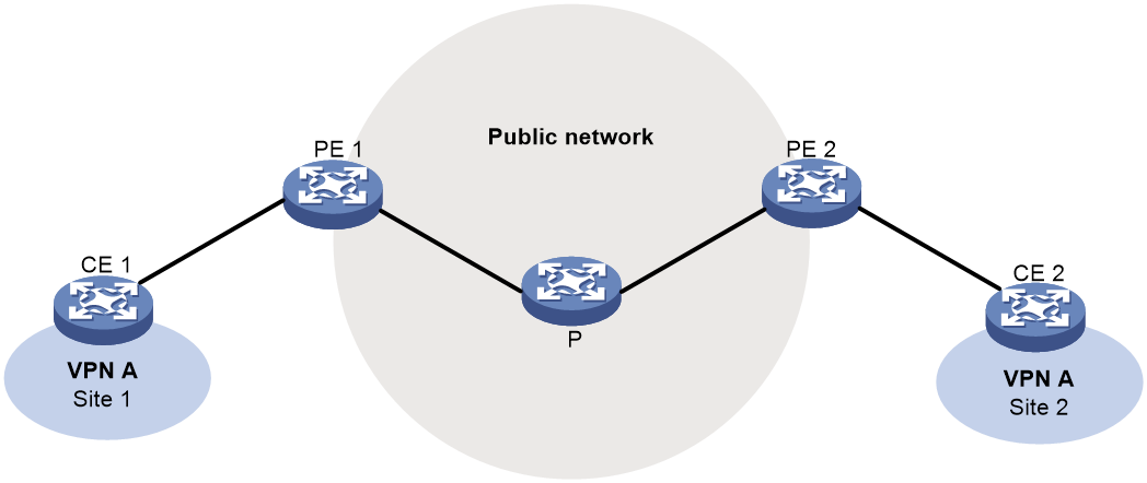
IPv6 multicast traffic forwarding over the IPv4 public network is as follows:
1. CE 1 forwards an IPv6 multicast packet for VPN instance VPN A to PE 1.
2. PE 1 encapsulates the IPv6 multicast packet with an IPv4 packet header and transmits the IPv4 packet in the IPv4 backbone network.
3. PE 2 decapsulates the IPv4 packet and forwards the IPv6 multicast packet to CE 2.
Protocols and standards
· RFC 6037, Cisco Systems' Solution for Multicast in BGP/MPLS IP VPNs
· RFC 6513, Multicast in MPLS/BGP IP VPNs
· RFC 6514, BGP Encodings and Procedures for Multicast in MPLS/BGP IP VPNs
Configuring multicast VPN
Restrictions and guidelines: Multicast VPN configuration
The MTIs take effect only after the default group and the MVPN source interface are specified and the MVPN source interface obtains an public IP address.
The PIM mode on an MTI must be the same as the PIM mode running on the VPN instance to which the MTI belongs. When a minimum of one interface on the VPN instance is enabled with PIM, the MTI is enabled with PIM accordingly. When all interfaces on the VPN instance are disabled with PIM, PIM is also disabled on the MTI.
Configure multicast VPN on PEs.
Multicast VPN tasks at a glance
MDT-based MVPN tasks at a glance
To configure MDT-based MVPN, perform the following tasks:
a. Enabling IP multicast routing for a VPN instance
b. Creating an MDT-based MVPN instance
c. Creating an MVPN address family
d. Specifying the default group
e. Specifying the MVPN source interface
f. (Optional.) Configuring MDT switchover parameters
g. (Optional.) Configuring the RPF vector feature
h. (Optional.) Enabling data group reuse logging
If PIM-SSM is running on the public network, you must configure BGP MDT.
a. Configuring BGP MDT peers or peer groups
b. (Optional.) Limiting BGP MDT routes received from a peer or peer group
c. (Optional.) Configuring a BGP MDT route reflector
d. (Optional.) Configuring BGP MDT optimal route selection delay
e. (Optional.) Preferring routes learned from the specified peer or peer group during optimal route selection
RSVP-TE-based MVPN tasks at a glance
To configure RSVP-TE-based MVPN, perform the following tasks on PEs:
1. Enabling IP multicast routing for a VPN instance
2. Configuring BGP IPv4 MVPN route exchange
4. Creating an RSVP-TE-based MVPN instance
5. Creating an MVPN IPv4 address family
6. Specifying the MVPN source interface
7. Enabling inclusive tunnel creation
8. (Optional.) Enabling selective tunnel creation
9. (Optional.) Setting the tunnel switchover delay
mLDP-TE-based MVPN tasks at a glance
To configure mLDP-based MVPN, perform the following tasks on PEs:
1. Enabling IP multicast routing for a VPN instance
2. Configuring BGP IPv4 MVPN route exchange
3. Configuring BGP IPv6 MVPN route exchange
6. Creating an mLDP-based MVPN instance
7. Creating an MVPN IPv4 address family
8. Specifying the MVPN source interface
9. Enabling inclusive tunnel creation
10. (Optional.) Enabling selective tunnel creation
11. (Optional.) Setting the tunnel switchover delay
12. (Optional.) Enabling inter-AS auto-discovery
BIER-based MVPN tasks at a glance
To configure BIER-based MVPN, perform the following tasks on PEs:
1. Enabling IP multicast routing for a VPN instance
2. Configuring BGP IPv4 MVPN route exchange
3. Configuring BGP IPv6 MVPN route exchange
4. Allowing the device to add extended community attributes to C-multicast routes sent to BGP peers
5. Creating a BIER-based MVPN instance
6. Creating an MVPN IPv4 address family
7. Specifying the MVPN source interface
8. Enabling IPv6 underlay for MVPN
9. Configuring multicast service prefix information
10. Specifying the multicast service source address
11. (Optional.) Enabling inclusive tunnel creation
12. (Optional.) Enabling selective tunnel creation
13. (Optional.) Setting the tunnel holddown timer
14. (Optional.) Enabling inter-AS auto-discovery
15. (Optional.) Configuring FRR
Configuring MDT-based MVPN
Prerequisites for configuring MDT-based MVPN
Before you configure MDT-based MVPN, complete the following tasks:
· Configure a unicast routing protocol on the public network.
· Configure MPLS L3VPN on the public network.
· Configure PIM-DM, PIM-SM or PIM-SSM on the public network.
Enabling IP multicast routing for a VPN instance
1. Enter system view.
system-view
2. Create a VPN instance and enter its view.
ip vpn-instance vpn-instance-name
For more information about this command, see MPLS Command Reference.
3. Configure an RD for the VPN instance.
route-distinguisher route-distinguisher
For more information about this command, see MPLS Command Reference.
4. Return to system view.
quit
5. Enter interface view.
interface interface-type interface-number
6. Associate the interface with the VPN instance.
ip binding vpn-instance vpn-instance-name
By default, an interface is associated with no VPN instance and belongs to the public network.
For more information about this command, see MPLS Command Reference.
7. Return to system view.
quit
8. Enable IP multicast routing for the VPN instance and enter MRIB view of the VPN instance.
multicast routing vpn-instance vpn-instance-name
By default, IPv4 multicast routing is disabled for a VPN instance.
For more information about this command, see IP Multicast Command Reference.
Creating an MDT-based MVPN instance
About this task
To provide multicast services for a VPN instance, you must create an MDT-based MVPN instance on PEs that belong to the VPN instance. After the MVPN instance is created, the system automatically creates MTIs and binds them with the VPN instance.
You can create one or more MDT-based MVPN instances on a PE.
Procedure
1. Enter system view.
system-view
2. Create an MDT-based MVPN instance and enter MVPN view.
multicast-vpn vpn-instance vpn-instance-name mode mdt
Creating an MVPN address family
About this task
You must create an MVPN IPv4 address family for a VPN instance before you can perform other MVPN VPN configuration tasks for the VPN instance. For a VPN instance, configurations in MVPN IPv4 address family view applies to IPv4 multicast packets of the instance.
Procedure
1. Enter system view.
system-view
2. Enter MVPN view of a VPN instance.
multicast-vpn vpn-instance vpn-instance-name mode mdt
3. Create an MVPN address family and enter MVPN address family view.
address-family ipv4
Specifying the default group
Restrictions and guidelines
You must specify the same default group on all PEs that belong to the same MVPN.
The default group for an MVPN must be different from the default group and the data group used by any other MVPN.
For an MVPN that transmits both IPv4 and IPv6 multicast packets, you must specify the same default group in MVPN IPv4 address family view and IPv6 address family view.
Procedure
1. Enter system view.
system-view
2. Enter MVPN view.
multicast-vpn vpn-instance vpn-instance-name mode mdt
3. Enter MVPN address family view.
address-family ipv4
4. Specify the default group.
default-group group-address
Specifying the MVPN source interface
About this task
An MTI of a VPN instance uses the IP address of the MVPN source interface as the source address to encapsulate multicast packets for the VPN instance.
Restrictions and guidelines
For the PE to obtain correct routing information, you must specify the interface used for establishing BGP peer relationship as the MVPN source interface.
The MTI takes effect only after the default group and MVPN source interface are specified and the MTI obtains the public IP address of the MVPN source interface.
The MVPN source interface can be configured to borrow the IP address of a loopback interface. As a best practice, specify the mask length for the loopback interface address as 32.
To use IP unnumbered, you must also configure OSPF, IS-IS, and LLDP. For information about configuring OSPF, IS-IS, and LLDP, see "Configuring PIM."
Procedure
1. Enter system view.
system-view
2. Enter MVPN view.
multicast-vpn vpn-instance vpn-instance-name mode mdt
3. Enter MVPN address family view.
address-family ipv4
4. Specify the MVPN source interface.
source interface-type interface-number
By default, no MVPN source interface is specified.
Configuring MDT switchover parameters
About this task
In some cases, the traffic rate of the private network multicast data might fluctuate around the MDT switchover threshold. To avoid frequent switching of multicast traffic between the default MDT and the data MDT, you can specify a data-delay period and a data hold-down period.
· MDT switchover does not take place immediately after the multicast traffic rate exceeds the switchover threshold. It takes place after a data-delay period, during which the traffic rate must stay higher than the switchover threshold.
· Likewise, a backward switchover does not take place immediately after the multicast traffic rate drops below the MDT switchover threshold. It takes place after a data hold-down period, during which the traffic rate must stay lower than the switchover threshold.
Restrictions and guidelines
On a PE, the data group range for an MVPN cannot include the default group or data groups of any other MVPN.
All VPN instances share the data group resources. As a best practice to avoid data group resource exhaustion, specify a reasonable data group range for a VPN instance.
If the public network runs PIM-SSM, the data group range for an MVPN on a PE can overlap with data group ranges for other MDs on other PEs.
Procedure
1. Enter system view.
system-view
2. Enter MVPN view.
multicast-vpn vpn-instance vpn-instance-name mode mdt
3. Enter MVPN address family view.
address-family ipv4
4. Configure the data group range and the switchover criteria.
data-group group-address { mask-length | mask } [ threshold threshold-value | acl acl-number ] *
By default, no data group range exists, and the device never initiates a switchover of the default MDT to a data MDT.
5. Set the data-delay period.
data-delay delay
By default, the data-delay period is 3 seconds.
6. Set the data hold-down period.
data-holddown delay
By default, the data hold-down period is 60 seconds.
Configuring the RPF vector feature
About this task
This feature enables the device to insert the RPF vector (IP address of the ASBR in the local AS) in PIM join messages for other devices to perform RPF check.
Restrictions and guidelines
Perform this task on PEs that have attached receivers.
For the device to work with other manufacturers' products on the RPF vector, you must enable RPF vector compatibility for all H3C P devices and H3C PE devices on the public network.
Procedure
1. Enter system view.
system-view
2. Enter MRIB view of a VPN instance.
multicast routing vpn-instance vpn-instance-name
3. Enable the RPF vector feature.
rpf proxy vector
By default, the RPF vector feature is disabled.
4. Return to system view.
quit
5. Enable RPF vector compatibility.
multicast rpf-proxy-vector compatible
By default, RPF vector compatibility is disabled.
Enabling data group reuse logging
About this task
For a given VPN, the number of VPN multicast streams to be switched over to data MDTs might exceed the number of addresses in the data group range. In this case, the VPN instance on the source-side PE can reuse the addresses in the address range. With data group reuse logging enabled, the address reuse information will be logged. Perform this task on PEs.
The group address reuse logging information has a severity level informational. For more information about the logging information, see Network Management and Monitoring Configuration Guide.
Procedure
1. Enter system view.
system-view
2. Enter MVPN view.
multicast-vpn vpn-instance vpn-instance-name mode mdt
3. Enter MVPN address family view.
address-family ipv4
4. Enable data group reuse logging.
log data-group-reuse
By default, data group reuse logging is disabled.
Configuring BGP MDT
Configuring BGP MDT peers or peer groups
About this task
Perform this task so that the PE can exchange MDT information with the BGP peer or peer group. MDT information includes the IP address of the PE and default group to which the PE belongs. On a public network running PIM-SSM, the multicast VPN establishes a default MDT rooted at the PE (multicast source) based on the MDT information.
Prerequisites
Before you configure a BGP MDT peer or peer group, you must create a BGP peer or peer group in BGP instance view. For more information about creating a BGP peer or peer group, see BGP configuration in Layer 3—IP Routing Configuration Guide.
Procedure
1. Enter system view.
system-view
2. Enter BGP instance view.
bgp as-number [ instance instance-name ]
3. Create a BGP IPv4 MDT address family and enter its view.
address-family ipv4 mdt
By default, no BGP IPv4 address family exists.
4. Enable the device to exchange MDT routing information with the BGP peer or the peer group.
peer { group-name | ip-address [ mask-length ] } enable
By default, the device cannot exchange BGP MDT routing information with a BGP peer or peer group.
For more information about this command, see BGP commands in Layer 3—IP Routing Command Reference.
Limiting BGP MDT routes received from a peer or peer group
About this task
This feature can prevent attacks that send a large number of BGP MDT routes to the router.
If the number of routes received from a peer or peer group exceeds the upper limit, the router takes one of the following actions based on your configuration:
· Tears down the BGP session to the peer or peer group and does not attempt to re-establish the session.
· Continues to receive routes from the peer or peer group and generates a log message.
· Retains the session to the peer or peer group, but it discards excess routes and generates a log message.
· Tears down the BGP session to the peer or peer group and, after a specific period of time, re-establishes a BGP session to the peer or peer group.
You can specify a percentage threshold for the router to generate a log message. When the ratio of the number of received routes to the maximum number reaches the percentage value, the router generates a log message.
Procedure
1. Enter system view.
system-view
2. Enter BGP instance view.
bgp as-number [ instance instance-name ]
3. Enter BGP IPv4 MDT address family view.
address-family ipv4 mdt
4. Specify the maximum number of BGP MDT routes that a router can receive from a peer or peer group.
peer { group-name | ipv4-address [ mask-length ] } route-limit prefix-number [ { alert-only | discard | reconnect reconnect-time } | percentage-value ] *
By default, the number of BGP MDT routes that a router can receive from a peer or peer group is not limited.
For more information about this command, see BGP commands in Layer 3—IP Routing Command Reference.
Configuring a BGP MDT route reflector
About this task
· Configuring a BGP MDT route reflector—BGP MDT peers in the same AS must be fully meshed to maintain connectivity. However, when multiple BGP MDT peers exist in an AS, connection establishment among them might result in increased costs. To reduce connections between BGP MDT peers, you can configure one of them as a route reflector and specify other devices as clients.
· Disabling routing reflection between clients—When clients establish BGP MDT connections with the route reflector, the route reflector forwards (or reflects) BGP MDT routing information between clients. The clients are not required to be fully meshed. To save bandwidth if the clients have been fully meshed, you can disable the routing reflection between clients by using the undo reflect between-clients command.
· Configuring the cluster ID of the route reflector—The route reflector and its clients form a cluster. Typically, a cluster has only one route reflector whose router ID identifies the cluster. However, you can configure several route reflectors in a cluster to improve network reliability. To avoid routing loops, make sure the route reflectors in a cluster have the same cluster ID.
Procedure
1. Enter system view.
system-view
2. Enter BGP instance view.
bgp as-number [ instance instance-name ]
3. Enter BGP IPv4 MDT address family view.
address-family ipv4 mdt
4. Configure the device as a route reflector and specify its peers or peer groups as clients.
peer { group-name | ip-address [ mask-length ] } reflect-client
By default, neither route reflectors nor clients exist.
5. (Optional.) Disable route reflection between clients.
undo reflect between-clients
By default, route reflection between clients is disabled.
For more information about this command, see BGP commands in Layer 3—IP Routing Command Reference.
6. (Optional.) Configure the cluster ID of the route reflector.
reflector cluster-id { cluster-id | ip-address }
By default, a route reflector uses its router ID as the cluster ID.
For more information about this command, see BGP commands in Layer 3—IP Routing Command Reference.
Configuring BGP MDT optimal route selection delay
1. Enter system view.
system-view
2. Enter BGP instance view.
bgp as-number [ instance instance-name ]
3. Enter BGP IPv4 MDT address family view.
address-family ipv4 mdt
4. Set the optimal route selection delay timer.
route-select delay delay-value
By default, the optimal route selection delay timer is 0 seconds, which means optimal route selection is not delayed.
For more information about this command, see BGP commands in Layer 3—IP Routing Command Reference.
Preferring routes learned from the specified peer or peer group during optimal route selection
About this task
Routes learned from the specified peer or peer group take precedence over routes learned from other peers or peer groups if these routes have the same prefix. BGP uses this rule to continue route selection if it fails to select an optimal route by using the peer type selection rule. If BGP still fails route selection, it uses the IGP metric selection rule to select an optimal route.
Procedure
1. Enter system view.
system-view
2. Enter BGP instance view.
bgp as-number [ instance instance-name ]
3. Enter BGP IPv4 MDT address family view.
address-family ipv4 mdt
4. Prefer routes learned from the specified peer or peer group during optimal route selection.
peer { group-name | ipv4-address [ mask-length ] } high-priority
By default, BGP does not prefer routes learned from any peer or peer groups during optimal route selection.
For more information about this command, see BGP commands in Layer 3—IP Routing Command Reference.
Configuring RSVP-TE-based MVPN
Restrictions and guidelines for RSVP-TE-based MVPN
This feature is available only for the following cards:
|
Card category |
Cards |
|
CEPC |
CEPC-XP4LX, CEPC-XP24LX, CEPC-XP48RX, CEPC-CP4RX, CEPC-CP4RXA, CEPC-CP4RX-L, CEPC-CQ8L, CEPC-CQ8LA, CEPC-CQ8L1A, CEPC-CQ16L1 |
|
CSPEX |
CSPEX-1304X, CSPEX-1404X, CSPEX-1502X, CSPEX-1504X, CSPEX-1504XA, CSPEX-1602X, CSPEX-1602XA, CSPEX-1804X, CSPEX-1512X, CSPEX-1612X, CSPEX-1812X, CSPEX-1802X, CSPEX-1802XA, CSPEX-2612XA, CSPEX-1812X-E, CSPEX-2304X-G, CSPEX-1502XA, CSPEX-1104-E |
|
SPE |
RX-SPE200, RX-SPE200-E |
Prerequisites for configuring RSVP-TE-based MVPN
Before you configure RSVP-TE-based MVPN, complete the following tasks:
· Configure a unicast routing protocol on the public network.
· Configure MPLS TE and RSVP on the public network.
· Configure BGP to enable PEs to mutually establish neighbor relationship.
Enabling IP multicast routing for a VPN instance
1. Enter system view.
system-view
2. Create a VPN instance and enter its view.
ip vpn-instance vpn-instance-name
For more information about this command, see MPLS Command Reference.
3. Configure an RD for the VPN instance.
route-distinguisher route-distinguisher
For more information about this command, see MPLS Command Reference.
4. Return to system view.
quit
5. Enter interface view.
interface interface-type interface-number
6. Associate the interface with the VPN instance.
ip binding vpn-instance vpn-instance-name
By default, an interface is associated with no VPN instance and belongs to the public network.
For more information about this command, see MPLS Command Reference.
7. Return to system view.
quit
8. Enable IP multicast routing for the VPN instance and enter MRIB view of the VPN instance.
IPv4:
multicast routing vpn-instance vpn-instance-name
By default, IPv4 multicast routing is disabled for a VPN instance.
For more information about this command, see IP Multicast Command Reference.
Configuring BGP IPv4 MVPN route exchange
1. Enter system view.
system-view
2. Enter BGP instance view.
bgp as-number [ instance instance-name ]
3. Specify a BGP MVPN peer and its AS number.
peer ipv4-address as-number as-number
4. Enter BGP IPv4 MVPN address family view.
address-family ipv4 mvpn
5. Enable BGP to exchange IPv4 unicast routing information with dynamic BGP peers.
peer ipv4-address mask-length enable
By default, BGP cannot exchange IPv4 unicast routing information with dynamic BGP peers.
For more information about this command, see BGP commands in Layer 3—IP Routing Command Reference.
6. (Optional.) Specify the maximum number of routes that a router can receive from a peer or peer group.
peer { group-name | ipv4-address [ mask-length ] } route-limit prefix-number [ { alert-only | discard | reconnect reconnect-time } | percentage-value ] *
By default, the number of routes that a router can receive from a peer or peer group is not limited.
For more information about this command, see BGP commands in Layer 3—IP Routing Command Reference.
7. (Optional.) Configure the BGP Additional Paths feature.
a. Configure the BGP Additional Paths capabilities.
peer { group-name | ipv4-address [ mask-length ] | ipv6-address [ prefix-length ] } additional-paths { receive | send } *
By default, no BGP Additional Paths capabilities are configured
b. Set the maximum number of Add-Path optimal routes that can be advertised to a peer or peer group.
peer { group-name | ipv4-address [ mask-length ] | ipv6-address [ prefix-length ] } advertise additional-paths best number
By default, a maximum number of one Add-Path optimal route can be advertised to a peer or peer group.
c. Set the maximum number of Add-Path optimal routes that can be advertised to all peers.
additional-paths select-best best-number
By default, a maximum number of one Add-Path optimal route can be advertised to all peers.
For more information about the commands in this step, see BGP commands in Layer 3—IP Routing Command Reference.
8. (Optional.) Advertise the COMMUNITY or Large Community attribute to a peer or peer group.
¡ Advertise the COMMUNITY attribute to a peer or peer group.
peer { group-name | ipv4-address [ mask-length ] } advertise-community
By default, the COMMUNITY attribute advertisement to a peer or peer group is disabled.
¡ Advertise the Large Community attribute to a peer or peer group.
peer { group-name | ipv4-address [ mask-length ] } advertise-large-community
By default, the Large Community attribute advertisement to a peer or peer group is disabled.
For more information about the commands in this step, see BGP commands in Layer 3—IP Routing Command Reference.
9. (Optional.) Disable route target filtering of received BGP IPv4 MVPN routes.
undo policy vpn-target
By default, a PE device filters route targets for received BGP IPv4 MVPN routes.
10. (Optional.) Set the optimal route selection delay timer.
route-select delay delay-value
By default, the optimal route selection delay timer is 0 seconds, which means optimal route selection is not delayed.
For more information about this command, see BGP commands in Layer 3—IP Routing Command Reference.
11. Prefer routes learned from the specified peer or peer group during optimal route selection.
peer { group-name | ipv4-address [ mask-length ] | ipv6-address [ prefix-length ] } high-priority
By default, BGP does not prefer routes learned from any peer or peer groups during optimal route selection.
For more information about this command, see BGP commands in Layer 3—IP Routing Command Reference.
Allowing the device to add extended community attributes to C-multicast routes sent to BGP VPNv4 peers
About this task
The following BGP extended community attributes are used to identify the route originator of a BGP VPNv4 route:
· Source AS—Carries the number of AS where the MVPN source resides. The format of this attribute is 32-bit AS number:0, for example, 100:0.
· VRF Route Import—Carries the originating address and the VPN instance to which the BGP VPNv4 route belongs. The format of the attribute is 32-bit originating address:VPN instance index, for example, 192.168.122.15:1. The value of the originating address depends on the MVPN source interface configuration.
¡ If the source command is used to specify the MVPN source interface, the originating address is the IP address of the MVPN source interface.
¡ If the source command is not used, the originating address is the router ID of the BGP instance to which the device belongs.
Prerequisites
Before you perform this task, you must establish BGP VPNv4 peer relationship and BGP IPv4 MVPN neighbor relationship between the device and other devices.
Procedure
1. Enter system view.
system-view
2. Enter BGP instance view.
bgp as-number [ instance instance-name ]
3. Enter BGP VPNv4 address family view.
address-family vpnv4
For more information about this command, see BGP commands in Layer 3-IP Routing Command Reference.
4. Allow the device to add Source AS and VRF Route Import extended community attributes to routes sent to BGP VPNv4 peers.
mvpn-advertise-rt-import
By default, the device is disabled from adding Source AS and RF Route Import extended community attributes to routes sent to BGP VPNv4 peers.
Creating an RSVP-TE-based MVPN instance
About this task
You can create one or more RSVP-TE-based MVPN instances on a PE device.
A VPN instance supports only one MVPN mode.
Procedure
1. Enter system view.
system-view
2. Create an RSVP-TE-based MVPN instance and enter its view.
multicast-vpn vpn-instance vpn-instance-name mode rsvp-te
Creating an MVPN IPv4 address family
Restrictions and guidelines
Configurations in MVPN IPv4 address family view apply only to IPv4 multicast.
Procedure
1. Enter system view.
system-view
2. Enter MVPN view.
multicast-vpn vpn-instance vpn-instance-name mode rsvp-te
3. Create an MVPN IPv4 address family and enter its view.
address-family ipv4
Specifying the MVPN source interface
About this task
An RSVP tunnel uses the IP address of the MVPN source interface as the source address to encapsulate multicast packets from the private network.
Restrictions and guidelines
For the PE to obtain correct routing information, you must specify the interface used for establishing BGP peer relationship as the MVPN source interface.
The MVPN source interface can be configured to borrow the IP address of a loopback interface. As a best practice, specify the mask length for the loopback interface address as 32.
To use IP unnumbered, you must also configure OSPF, IS-IS, and LLDP. For information about configuring OSPF, IS-IS, and LLDP, see "Configuring PIM."
Procedure
1. Enter system view.
system-view
2. Enter MVPN view.
multicast-vpn vpn-instance vpn-instance-name mode rsvp-te
3. Enter MVPN IPv4 address family view.
address-family ipv4
4. Specify the MVPN source interface.
source interface-type interface-number
By default, no MVPN source interface is specified.
Enabling inclusive tunnel creation
Restrictions and guidelines
Once created, the inclusive tunnel always exists whether the multicast traffic is present or not.
Only one inclusive tunnel can be established between two PEs in an MVPN.
Procedure
1. Enter system view.
system-view
2. Enter MVPN view.
multicast-vpn vpn-instance vpn-instance-name mode rsvp-te
3. Enter MVPN IPv4 address family view.
address-family ipv4
4. Enable dynamic inclusive tunnel creation.
inclusive-tunnel dynamic
By default, dynamic inclusive tunnel creation is disabled.
Enabling selective tunnel creation
About this task
Multicast traffic that matches the tunnel switchover criterion is switched over to selective tunnels from the inclusive tunnel after selective tunnel are created.
Restrictions and guidelines
Selective tunnels are created only after the multicast traffic is transmitted over the inclusive tunnel.
Multicast packets of multiple (S, G) entries can share one selective tunnel.
Multiple selective tunnels can be created between two PEs in an MVPN. These selective tunnels are independent from one another.
Procedure
1. Enter system view.
system-view
2. Enter MVPN view.
multicast-vpn vpn-instance vpn-instance-name mode rsvp-te
3. Enter MVPN IPv4 address family view.
address-family ipv4
4. Enable dynamic selective tunnel creation.
selective-tunnel dynamic [ acl { ipv4-acl-number | name ipv4-acl-name } ]
By default, dynamic selective tunnel creation is disabled.
Setting the tunnel switchover delay
About this task
To avoid multicast data loss during tunnel switchover, adjust the delay time for multicast data to switch over from the inclusive tunnel to selective tunnels.
Procedure
1. Enter system view.
system-view
2. Enter MVPN view.
multicast-vpn vpn-instance vpn-instance-name mode rsvp-te
3. Enter MVPN IPv4 address family view.
address-family ipv4
4. Set the tunnel switchover delay.
selective-tunnel delay delay
By default, the tunnel switchover delay is 3 seconds.
Configuring mLDP-based MVPN
Restrictions and guidelines for mLDP-based MVPN
This feature is available only for the following cards:
|
Card category |
Cards |
|
CEPC |
CEPC-XP4LX, CEPC-XP24LX, CEPC-XP48RX, CEPC-CP4RX, CEPC-CP4RXA, CEPC-CP4RX-L, CEPC-CQ8L, CEPC-CQ8LA, CEPC-CQ8L1A, CEPC-CQ16L1 |
|
CSPEX |
CSPEX-1304X, CSPEX-1404X, CSPEX-1502X, CSPEX-1504X, CSPEX-1504XA, CSPEX-1602X, CSPEX-1602XA, CSPEX-1804X, CSPEX-1512X, CSPEX-1612X, CSPEX-1812X, CSPEX-1802X, CSPEX-1802XA, CSPEX-2612XA, CSPEX-1812X-E, CSPEX-2304X-G, CSPEX-1502XA, CSPEX-1104-E |
|
SPE |
RX-SPE200, RX-SPE200-E |
Prerequisites for configuring mLDP-based MVPN
Before you configure mLDP-based MVPN, complete the following tasks:
· Configure a unicast routing protocol on the public network.
· Configure MPLS LDP on the public network.
· Configure BGP to enable PEs to mutually establish neighbor relationship.
Enabling IP multicast routing for a VPN instance
1. Enter system view.
system-view
2. Create a VPN instance and enter its view.
ip vpn-instance vpn-instance-name
For more information about this command, see MPLS L3VPN commands in MPLS Command Reference.
3. Configure an RD for the VPN instance.
route-distinguisher route-distinguisher
For more information about this command, see MPLS L3VPN commands in MPLS Command Reference.
4. Return to system view.
quit
5. Enter interface view.
interface interface-type interface-number
6. Associate the interface with the VPN instance.
ip binding vpn-instance vpn-instance-name
By default, an interface is associated with no VPN instance and belongs to the public network.
For more information about this command, see MPLS L3VPN commands in MPLS Command Reference.
7. Return to system view.
quit
8. Enable IP multicast routing for the VPN instance and enter MRIB view of the VPN instance.
IPv4:
multicast routing vpn-instance vpn-instance-name
By default, IP multicast routing is disabled for a VPN instance.
For more information about the commands, see multicast routing and forwarding commands in IP Multicast Command Reference.
Configuring BGP IPv4 MVPN route exchange
1. Enter system view.
system-view
2. Enter BGP instance view.
bgp as-number [ instance instance-name ]
3. Specify a BGP MVPN peer and its AS number.
peer ipv4-address as-number as-number
4. Enter BGP IPv4 MVPN address family view.
address-family ipv4 mvpn
5. Enable BGP to exchange IPv4 unicast routing information with BGP peers.
peer ipv4-address enable
By default, BGP cannot exchange IPv4 unicast routing information with BGP peers.
For more information about this command, see BGP commands in Layer 3—IP Routing Command Reference.
6. (Optional.) Specify the maximum number of routes that a router can receive from a peer or peer group.
peer { group-name | ipv4-address [ mask-length ] } route-limit prefix-number [ { alert-only | discard | reconnect reconnect-time } | percentage-value ] *
By default, the number of routes that a router can receive from a peer or peer group is not limited.
For more information about this command, see BGP commands in Layer 3—IP Routing Command Reference.
7. (Optional.) Configure the BGP Additional Paths feature.
a. Configure the BGP Additional Paths capabilities.
peer { group-name | ipv4-address [ mask-length ] | ipv6-address [ prefix-length ] } additional-paths { receive | send } *
By default, no BGP Additional Paths capabilities are configured
b. Set the maximum number of Add-Path optimal routes that can be advertised to a peer or peer group.
peer { group-name | ipv4-address [ mask-length ] | ipv6-address [ prefix-length ] } advertise additional-paths best number
By default, a maximum number of one Add-Path optimal route can be advertised to a peer or peer group.
c. Set the maximum number of Add-Path optimal routes that can be advertised to all peers.
additional-paths select-best best-number
By default, a maximum number of one Add-Path optimal route can be advertised to all peers.
For more information about the commands in this step, see BGP commands in Layer 3—IP Routing Command Reference.
8. (Optional.) Advertise the COMMUNITY or Large Community attribute to a peer or peer group.
¡ Advertise the COMMUNITY attribute to a peer or peer group.
peer { group-name | ipv4-address [ mask-length ] } advertise-community
By default, the COMMUNITY attribute advertisement to a peer or peer group is disabled.
¡ Advertise the Large Community attribute to a peer or peer group.
peer { group-name | ipv4-address [ mask-length ] } advertise-large-community
By default, the Large Community attribute advertisement to a peer or peer group is disabled.
For more information about the commands in this step, see BGP commands in Layer 3—IP Routing Command Reference.
9. (Optional.) Disable route target filtering of received BGP IPv4 MVPN routes.
undo policy vpn-target
By default, a PE device filters route targets for received BGP IPv4 MVPN routes.
10. (Optional.) Set the optimal route selection delay timer.
route-select delay delay-value
By default, the optimal route selection delay timer is 0 seconds, which means optimal route selection is not delayed.
For more information about this command, see BGP commands in Layer 3—IP Routing Command Reference.
11. Prefer routes learned from the specified peer or peer group during optimal route selection.
peer { group-name | ipv4-address [ mask-length ] | ipv6-address [ prefix-length ] } high-priority
By default, BGP does not prefer routes learned from any peer or peer groups during optimal route selection.
For more information about this command, see BGP commands in Layer 3—IP Routing Command Reference.
Configuring BGP IPv6 MVPN route exchange
1. Enter system view.
system-view
2. Enter BGP instance view.
bgp as-number [ instance instance-name ]
3. Specify a BGP MVPN peer and its AS number.
peer ipv6-address as-number as-number
4. Enter BGP IPv6 MVPN address family view.
address-family ipv6 mvpn
5. Enable BGP to exchange IPv6 unicast routing information with dynamic BGP peers.
peer ipv4-address enable
By default, BGP cannot exchange IPv6 unicast routing information with dynamic BGP peers.
For more information about this command, see BGP commands in Layer 3—IP Routing Command Reference.
6. (Optional.) Specify the maximum number of routes that a router can receive from a peer or peer group.
peer { group-name | ipv4-address [ mask-length ] } route-limit prefix-number [ { alert-only | discard | reconnect reconnect-time } | percentage-value ] *
By default, the number of routes that a router can receive from a peer or peer group is not limited.
For more information about this command, see BGP commands in Layer 3—IP Routing Command Reference.
7. (Optional.) Configure the BGP Additional Paths feature.
a. Configure the BGP Additional Paths capabilities.
peer { group-name | ipv4-address [ mask-length ] | ipv6-address [ prefix-length ] } additional-paths { receive | send } *
By default, no BGP Additional Paths capabilities are configured
b. Set the maximum number of Add-Path optimal routes that can be advertised to a peer or peer group.
peer { group-name | ipv4-address [ mask-length ] | ipv6-address [ prefix-length ] } advertise additional-paths best number
By default, a maximum number of one Add-Path optimal route can be advertised to a peer or peer group.
c. Set the maximum number of Add-Path optimal routes that can be advertised to all peers.
additional-paths select-best best-number
By default, a maximum number of one Add-Path optimal route can be advertised to all peers.
For more information about the commands in this step, see BGP commands in Layer 3—IP Routing Command Reference.
8. (Optional.) Advertise the COMMUNITY or Large Community attribute to a peer or peer group.
¡ Advertise the COMMUNITY attribute to a peer or peer group.
peer { group-name | ipv4-address [ mask-length ] } advertise-community
By default, the COMMUNITY attribute advertisement to a peer or peer group is disabled.
¡ Advertise the Large Community attribute to a peer or peer group.
peer { group-name | ipv4-address [ mask-length ] } advertise-large-community
By default, the Large Community attribute advertisement to a peer or peer group is disabled.
For more information about the commands in this step, see BGP commands in Layer 3—IP Routing Command Reference.
9. (Optional.) Disable route target filtering of received BGP IPv6 MVPN routes.
undo policy vpn-target
By default, a PE device filters route targets for received BGP IPv6 MVPN routes.
10. (Optional.) Set the optimal route selection delay timer.
route-select delay delay-value
By default, the optimal route selection delay timer is 0 seconds, which means optimal route selection is not delayed.
For more information about this command, see BGP commands in Layer 3—IP Routing Command Reference.
11. Prefer routes learned from the specified peer or peer group during optimal route selection.
peer { group-name | ipv4-address [ mask-length ] | ipv6-address [ prefix-length ] } high-priority
By default, BGP does not prefer routes learned from any peer or peer groups during optimal route selection.
For more information about this command, see BGP commands in Layer 3—IP Routing Command Reference.
Allowing the device to add extended community attributes to C-multicast routes sent to BGP VPNv4 peers
About this task
The following BGP extended community attributes are used to identify the route originator of a BGP VPNv4 route:
· Source AS—Carries the number of AS where the MVPN source resides. The format of this attribute is 32-bit AS number:0, for example, 100:0.
· VRF Route Import—Carries the originating address and the VPN instance to which the BGP VPNv4 route belongs. The format of the attribute is 32-bit originating address:VPN instance index, for example, 192.168.122.15:1. The value of the originating address depends on the MVPN source interface configuration.
¡ If the source command is used to specify the MVPN source interface, the originating address is the IP address of the MVPN source interface.
¡ If the source command is not used, the originating address is the router ID of the BGP instance to which the device belongs.
Prerequisites
Before you perform this task, you must establish BGP VPNv4 peer relationship and BGP IPv4 MVPN neighbor relationship between the device and other devices.
Procedure
1. Enter system view.
system-view
2. Enter BGP instance view.
bgp as-number [ instance instance-name ]
3. Enter BGP VPNv4 address family view.
address-family vpnv4
For more information about this command, see BGP commands in Layer 3-IP Routing Command Reference.
4. Allow the device to add Source AS and VRF Route Import extended community attributes to routes sent to BGP VPNv4 peers.
mvpn-advertise-rt-import
By default, the device is disabled from adding Source AS and RF Route Import extended community attributes to routes sent to BGP VPNv4 peers.
Allowing the device to add extended community attributes to C-multicast routes sent to BGP VPNv6 peers
About this task
The following BGP extended community attributes are used to identify the route originator of a BGP VPNv6 route:
· Source AS—Carries the number of the AS where the MVPN source resides. The format of this attribute is 32-bit AS number:0, for example, 100:0.
· VRF Route Import—Carries the originating address and the VPN instance to which the BGP VPNv6 route belongs. The format of the attribute is 32-bit originating address:VPN instance index, for example, 192.168.122.15:1. The value of the originating address depends on the MVPN source interface configuration.
¡ If the source command is used to specify the MVPN source interface, the originating address is the IP address of the MVPN source interface.
¡ If the source command is not used, the originating address is the router ID of the BGP instance to which the device belongs.
Prerequisites
Before you perform this task, you must establish BGP VPNv6 peer relationship and BGP IPv6 MVPN neighbor relationship between the device and other devices.
Procedure
1. Enter system view.
system-view
2. Enter BGP instance view.
bgp as-number [ instance instance-name ]
3. Enter BGP VPNv6 address family view.
address-family vpnv6
For more information about this command, see BGP commands in Layer 3-IP Routing Command Reference.
4. Allow the device to add Source AS and VRF Route Import extended community attributes to routes sent to BGP VPNv6 peers.
mvpn-advertise-rt-import
By default, the device is disabled from adding Source AS and RF Route Import extended community attributes to routes sent to BGP VPNv6 peers.
Creating an mLDP-based MVPN instance
About this task
You can create one or more mLDP-based MVPN instances on a PE device.
A VPN instance supports only one MVPN mode.
Procedure
1. Enter system view.
system-view
2. Create an mLDP-based MVPN instance and enter its view.
multicast-vpn vpn-instance vpn-instance-name mode mldp
Creating an MVPN IPv4 address family
Restrictions and guidelines
Configurations in MVPN IPv4 address family view apply only to IPv4 multicast.
Configurations in MVPN IPv6 address family view apply only to IPv6 multicast.
Procedure
1. Enter system view.
system-view
2. Enter MVPN view.
multicast-vpn vpn-instance vpn-instance-name mode mldp
3. Create an MVPN address family and enter its view.
IPv4:
address-family ipv4
IPv6:
address-family ipv6
Specifying the MVPN source interface
About this task
An mLDP tunnel uses the IP address of the MVPN source interface as the source address to encapsulate multicast packets from the private network.
Restrictions and guidelines
For the PE to obtain correct routing information, you must specify the interface used for establishing BGP peer relationship as the MVPN source interface.
For an MVPN that transmits both IPv4 and IPv6 multicast packets, you must specify the same MVPN source interface in MVPN IPv4 and IPv6 address family views.
The MVPN source interface can be configured to borrow the IP address of a loopback interface. As a best practice, specify the mask length for the loopback interface address as 32.
To use IP unnumbered, you must also configure OSPF, IS-IS, and LLDP. For information about configuring OSPF, IS-IS, and LLDP, see "Configuring PIM."
Procedure
1. Enter system view.
system-view
2. Enter MVPN view.
multicast-vpn vpn-instance vpn-instance-name mode mldp
3. Enter MVPN address family view.
IPv4:
address-family ipv4
IPv6:
address-family ipv6
4. Specify the MVPN source interface.
source interface-type interface-number
By default, no MVPN source interface is specified.
Enabling inclusive tunnel creation
Restrictions and guidelines
Once created, the inclusive tunnel always exists no matter whether multicast traffic is present or not.
Only one inclusive tunnel can be established between two PEs in an MVPN.
Procedure
1. Enter system view.
system-view
2. Enter MVPN view.
multicast-vpn vpn-instance vpn-instance-name mode mldp
3. Enter MVPN address family view.
IPv4:
address-family ipv4
IPv6:
address-family ipv6
4. Enable dynamic inclusive tunnel creation.
inclusive-tunnel dynamic
By default, dynamic inclusive tunnel creation is disabled.
Enabling selective tunnel creation
About this task
Multicast traffic that matches the tunnel switchover criterion is switched over to selective tunnels from the inclusive tunnel after selective tunnel are created.
Restrictions and guidelines
Selective tunnels are created only after the multicast traffic is transmitted over the inclusive tunnel.
Multicast packets for multiple (S, G) entries can share the same selective tunnel.
Multiple selective tunnels can be created between two PEs in an MVPN. These selective tunnels are independent from one another.
Procedure
1. Enter system view.
system-view
2. Enter MVPN view.
multicast-vpn vpn-instance vpn-instance-name mode mldp
3. Enter MVPN address family view.
IPv4:
address-family ipv4
IPv6:
address-family ipv6
4. Enable dynamic selective tunnel creation.
MVPN IPv4 address family:
selective-tunnel dynamic [ acl { acl ipv4-acl-number | name ipv4-acl-name } ]
MVPN IPv6 address family:
selective-tunnel dynamic [ acl { ipv6-acl-number | name ipv6-acl-name } ]
By default, dynamic selective tunnel creation is disabled.
Setting the tunnel switchover delay
About this task
To avoid multicast data loss during tunnel switchover, adjust the delay time for multicast data to switch over from the inclusive tunnel to selective tunnels.
Procedure
1. Enter system view.
system-view
2. Enter MVPN view.
multicast-vpn vpn-instance vpn-instance-name mode mldp
3. Enter MVPN address family view.
IPv4:
address-family ipv4
IPv6:
address-family ipv6
4. Set the tunnel switchover delay.
selective-tunnel delay delay
By default, the tunnel switchover delay is 3 seconds.
Enabling inter-AS auto-discovery
About this task
This feature inhibits the device from carrying the NO_EXPORT attribute in intra-AS A-D routes and S-PMSI A-D routes sent to BGP. Use this feature on the multicast source-side PE in an inter-AS MVPN scenario so that these routes can be discovered on the devices out of the local AS.
Procedure
1. Enter system view.
system-view
2. Enter MVPN view.
multicast-vpn vpn-instance vpn-instance-name mode mldp
3. Enter MVPN address family view.
IPv4:
address-family ipv4
IPv6:
address-family ipv6
4. Enable inter-AS auto-discovery.
auto-discovery inter-as
By default, inter-AS auto-discovery is disabled.
Configuring BIER-based MVPN
Restrictions: Hardware compatibility with BIER-based MVPN
This feature is available only for the following cards:
|
Card category |
Cards |
|
CEPC |
CEPC-CQ8L, CEPC-CQ8LA, CEPC-CQ8L1A, CEPC-CQ16L1 |
|
CSPEX |
CSPEX-1802X, CSPEX-1802XA, CSPEX-2612XA, CSPEX-1812X-E, CSPEX-2304X-G, CSPEX-1502XA |
|
SPE |
RX-SPE200-E |
Prerequisites for configuring BIER-based MVPN
Before you configure BIER-based MVPN, complete the following tasks:
· Configure a unicast routing protocol on the public network.
· Configure MPLS LDP on the public network.
· Configure BGP to enable PEs to mutually establish neighbor relationship
Enabling IP multicast routing for a VPN instance
1. Enter system view.
system-view
2. Create a VPN instance and enter its view.
ip vpn-instance vpn-instance-name
For more information about this command, see MPLS L3VPN commands in MPLS Command Reference.
3. Configure an RD for the VPN instance.
route-distinguisher route-distinguisher
For more information about this command, see MPLS L3VPN commands in MPLS Command Reference.
4. Return to system view.
quit
5. Enter interface view.
interface interface-type interface-number
6. Associate the interface with the VPN instance.
ip binding vpn-instance vpn-instance-name
By default, an interface is associated with no VPN instance and belongs to the public network.
For more information about this command, see MPLS L3VPN commands in MPLS Command Reference.
7. Return to system view.
quit
8. Enable IP multicast routing for the VPN instance and enter MRIB view of the VPN instance.
IPv4:
multicast routing vpn-instance vpn-instance-name
IPv6:
ipv6 multicast routing vpn-instance vpn-instance-name
By default, IP multicast routing is disabled for a VPN instance.
For more information about the commands, see multicast routing and forwarding commands and IPv6 multicast routing and forwarding commands in IP Multicast Command Reference.
Configuring BGP IPv4 MVPN route exchange
1. Enter system view.
system-view
2. Enter BGP instance view.
bgp as-number [ instance instance-name ]
3. Specify a BGP MVPN peer and its AS number.
peer ipv6-address as-number as-number
4. Enter BGP IPv4 MVPN address family view.
address-family ipv4 mvpn
5. Enable BGP to exchange IPv4 unicast routing information with BGP peers.
peer ipv6-address enable
By default, BGP cannot exchange IPv4 unicast routing information with BGP peers.
For more information about this command, see BGP commands in Layer 3—IP Routing Command Reference.
6. (Optional.) Specify the maximum number of routes that a router can receive from a peer or peer group.
peer { group-name | ipv4-address [ mask-length ] } route-limit prefix-number [ { alert-only | discard | reconnect reconnect-time } | percentage-value ] *
By default, the number of routes that a router can receive from a peer or peer group is not limited.
7. (Optional.) Configure the BGP Additional Paths feature.
a. Configure the BGP Additional Paths capabilities.
peer { group-name | ipv6-address [ prefix-length ] } additional-paths { receive | send } *
By default, no BGP Additional Paths capabilities are configured
b. Set the maximum number of Add-Path optimal routes that can be advertised to a peer or peer group.
peer { group-name | ipv6-address [ prefix-length ] } advertise additional-paths best number
By default, a maximum number of one Add-Path optimal route can be advertised to a peer or peer group.
c. Set the maximum number of Add-Path optimal routes that can be advertised to all peers.
additional-paths select-best best-number
By default, a maximum number of one Add-Path optimal route can be advertised to all peers.
For more information about the commands in this step, see BGP commands in Layer 3—IP Routing Command Reference.
8. (Optional.) Advertise the COMMUNITY or Large Community attribute to a peer or peer group.
¡ Advertise the COMMUNITY attribute to a peer or peer group.
peer { group-name | ipv6-address [ prefix-length ] } advertise-community
By default, the COMMUNITY attribute advertisement to a peer or peer group is disabled.
¡ Advertise the Large Community attribute to a peer or peer group.
peer { group-name | ipv6-address [ prefix-length ] } advertise-large-community
By default, the Large Community attribute advertisement to a peer or peer group is disabled.
For more information about the commands in this step, see BGP commands in Layer 3—IP Routing Command Reference.
9. (Optional.) Disable route target filtering of received BGP IPv4 MVPN routes.
undo policy vpn-target
By default, a PE device filters route targets for received BGP IPv4 MVPN routes.
10. (Optional.) Set the optimal route selection delay timer.
route-select delay delay-value
By default, the optimal route selection delay timer is 0 seconds, which means optimal route selection is not delayed.
For more information about this command, see BGP commands in Layer 3—IP Routing Command Reference.
Configuring BGP IPv6 MVPN route exchange
1. Enter system view.
system-view
2. Enter BGP instance view.
bgp as-number [ instance instance-name ]
3. Specify a BGP MVPN peer and its AS number.
peer ipv6-address as-number as-number
4. Enter BGP IPv6 MVPN address family view.
address-family ipv6 mvpn
5. Enable BGP to exchange IPv6 unicast routing information with dynamic BGP peers.
peer ipv6-address enable
By default, BGP cannot exchange IPv6 unicast routing information with dynamic BGP peers.
For more information about this command, see BGP commands in Layer 3—IP Routing Command Reference.
6. (Optional.) Specify the maximum number of routes that a router can receive from a peer or peer group.
peer { group-name | ipv4-address [ mask-length ] } route-limit prefix-number [ { alert-only | discard | reconnect reconnect-time } | percentage-value ] *
By default, the number of routes that a router can receive from a peer or peer group is not limited.
7. (Optional.) Configure the BGP Additional Paths feature.
a. Configure the BGP Additional Paths capabilities.
peer { group-name | ipv6-address [ prefix-length ] } additional-paths { receive | send } *
By default, no BGP Additional Paths capabilities are configured
b. Set the maximum number of Add-Path optimal routes that can be advertised to a peer or peer group.
peer { group-name | ipv6-address [ prefix-length ] } advertise additional-paths best number
By default, a maximum number of one Add-Path optimal route can be advertised to a peer or peer group.
c. Set the maximum number of Add-Path optimal routes that can be advertised to all peers.
additional-paths select-best best-number
By default, a maximum number of one Add-Path optimal route can be advertised to all peers.
For more information about the commands in this step, see BGP commands in Layer 3—IP Routing Command Reference.
8. (Optional.) Advertise the COMMUNITY or Large Community attribute to a peer or peer group.
¡ Advertise the COMMUNITY attribute to a peer or peer group.
peer { group-name | ipv6-address [ prefix-length ] } advertise-community
By default, the COMMUNITY attribute advertisement to a peer or peer group is disabled.
¡ Advertise the Large Community attribute to a peer or peer group.
peer { group-name | ipv6-address [ prefix-length ] } advertise-large-community
By default, the Large Community attribute advertisement to a peer or peer group is disabled.
For more information about the commands in this step, see BGP commands in Layer 3—IP Routing Command Reference.
9. (Optional.) Disable route target filtering of received BGP IPv6 MVPN routes.
undo policy vpn-target
By default, a PE device filters route targets for received BGP IPv6 MVPN routes.
10. (Optional.) Set the optimal route selection delay timer.
route-select delay delay-value
By default, the optimal route selection delay timer is 0 seconds, which means optimal route selection is not delayed.
For more information about this command, see BGP commands in Layer 3—IP Routing Command Reference.
Allowing the device to add extended community attributes to C-multicast routes sent to BGP peers
About this task
The following BGP extended community attributes are used to identify the route originator of a BGP VPN route and help the remote PE recurse MVPN routes to MVPN tunnels to generate correct multicast routing entries:
· Source AS—Carries the number of AS where the MVPN source resides. The format of this attribute is 32-bit AS number:0, for example, 100:0.
· VRF Route Import—Carries the originating address and the VPN instance or public network instance to which the BGP route belongs. The format of the attribute is 32-bit or 128-bit originating address:instance index, for example, 192.168.122.15:1. The index of the public network instance is 0. The value of the originating address depends on the MVPN source interface configuration.
¡ If the source command is used to specify the MVPN source interface, the originating address is the IP address of the MVPN source interface.
¡ If the source command is not used, the originating address is the router ID of the BGP instance to which the device belongs.
Restrictions and guidelines
· If the multicast source and multicast receivers are in the public network and IPv6 underlay is enabled for MVPN, perform this task in BGP IPv6 unicast address family view or BGP IPv6 multicast address family view. If IPv6 underlay is disabled for MVPN, perform this task in BGP IPv4 unicast address family view or BGP IPv4 multicast address family view.
· If the multicast source and multicast receivers are in a private network, perform this task in BGP VPNv4 address family view or BGP VPNv6 address family view.
· Perform this task in BGP IPv4 unicast address family view has the same effect as performing this task in BGP IPv4 multicast address family view. Perform this task in BGP IPv6 unicast address family view has the same effect as performing this task in BGP IPv6 multicast address family view.
· Perform this task in BGP IPv4 unicast address family view has the same effect as performing this task in BGP IPv6 unicast address family view.
· Before you perform this task in BGP IPv4 unicast address family view, BGP IPv4 multicast address family view, BGP VPNv4 address family view, you must establish BGP IPv4 MVPN peer relationship.
· Before you perform this task in BGP IPv6 unicast address family view, BGP IPv6 multicast address family view, BGP VPNv6 address family view, you must establish BGP IPv6 MVPN peer relationship.
Procedure
1. Enter system view.
system-view
2. Enter BGP instance view.
bgp as-number [ instance instance-name ]
3. Enter one of the following views:
¡ Enter BGP VPNv4 address family view.
address-family vpnv4
¡ Enter BGP VPNv6 address family view.
address-family vpnv6
¡ Enter BGP IPv4 unicast address family view.
address-family ipv4 [ unicast ]
¡ Enter BGP IPv4 multicast address family view.
address-family ipv4 multicast
¡ Enter BGP IPv6 unicast address family view.
address-family ipv6 [ unicast ]
¡ Enter BGP IPv6 multicast address family view.
address-family ipv6 multicast
4. Allow the device to add Source AS and VRF Route Import extended community attributes to routes sent to BGP peers.
mvpn-advertise-rt-import
By default, the device is disabled from adding Source AS and RF Route Import extended community attributes to routes sent to BGP peers.
Creating a BIER-based MVPN instance
About this task
You can create one or more BIER-based MVPN instances on a PE device to provide services for VPN instances or the public network instance.
The public network instance can be considered as a special VPN instance. The public network instance allows a PE to forward Layer 3 multicast traffic of the public network through a BIER tunnel.
Procedure
1. Enter system view.
system-view
2. Create a BIER-based MVPN instance and enter its view.
¡ Create an MVPN for a VPN instance and enter MVPN view.
multicast-vpn vpn-instance vpn-instance-name mode bier
¡ Create an MVPN for the public network instance and enter MVPN view.
multicast-vpn public-instance mode bier
Creating an MVPN IPv4 address family
Restrictions and guidelines
Configurations in MVPN IPv4 address family view apply only to IPv4 multicast.
Configurations in MVPN IPv6 address family view apply only to IPv6 multicast.
Procedure
1. Enter system view.
system-view
2. Enter MVPN view.
multicast-vpn vpn-instance vpn-instance-name mode bier
3. Create an MVPN address family and enter its view.
IPv4:
address-family ipv4
IPv6:
address-family ipv6
Specifying the MVPN source interface
About this task
A BIER tunnel uses the IP address of the MVPN source interface as the source address to encapsulate multicast packets from the private network.
Restrictions and guidelines
For an MVPN that transmits both IPv4 and IPv6 multicast packets, you must specify the same MVPN source interface in MVPN IPv4 and IPv6 address family views.
Procedure
1. Enter system view.
system-view
2. Enter MVPN view.
multicast-vpn vpn-instance vpn-instance-name mode bier
3. Enter MVPN address family view.
IPv4:
address-family ipv4
IPv6:
address-family ipv6
4. Specify the MVPN source interface.
source interface-type interface-number
By default, no MVPN source interface is specified.
Enabling IPv6 underlay for MVPN
About this task
By default, the originating router's IP address in a BGP MVPN route and the router ID in the VRF Route Import extended community are both IPv4 addresses. If the two addresses in a BGP MVPN route from another vendor's device are IPv6 addresses, BGP MVPN route exchange will fail. This function enables the device to carry the IPv6 address of the MVPN source interface in the two fields and to identify and accept BGP MVPN routes with IPv6 addresses.
Procedure
1. Enter system view.
system-view
2. Enter MVPN address family view.
IPv4:
address-family ipv4
IPv6:
address-family ipv6
3. Enable IPv6 underlay for MVPN.
ipv6 underlay enable
By default, IPv6 underlay is disabled for MVPN.
Configuring multicast service prefix information
About this task
In a BIER-based MVPN, you must configure a multicast service prefix for each multicast source-side PE. The PEs calculate a multicast service source address for identifying different MVPN instances based on the prefix address and length, multicast service ID (configured with the tunnel-source command) and the ID length. A PE uses this source address as the IPv6 source address when encapsulating multicast packets in BIER. This source address keeps unchanged when multicast packets are transmitted on the public network.
Restrictions and guidelines
Make sure the multicast service prefix addresses are different for different PEs and are different from the IPv6 addresses on the device. After the configuration, execute the display multicast-service-prefix configuration command to identify whether the multicast service prefixes are deployed successfully.
Procedure
1. Enter system view.
system-view
2. Configure multicast service prefix information.
multicast-service-prefix prefix-name ipv6-prefix ipv6-address prefix-length service-id-length id-length
By default, no multicast service prefix information is configured.
Specifying the multicast service source address
About this task
With this multicast service source address configured, a multicast source-side PE uses this address as the source IPv6 address for BIER encapsulation. This source address keeps unchanged when multicast packets are transmitted on the public network.
The multicast service source address is calculated based on the prefix address and length, and multicast service ID and ID length, which are configured by using the multicast-service-prefix command.
Restrictions and guidelines
To bind a multicast service source address to only one MVPN instance, you can configure only one multicast service address in one MVPN address family view.
Procedure
1. Enter system view.
system-view
2. Enter MVPN view.
multicast-vpn vpn-instance vpn-instance-name mode bier
3. Enter MVPN address family view.
IPv4:
address-family ipv4
IPv6:
address-family ipv6
4. Specify the multicast service source address.
tunnel-source multicast-service-prefix prefix-name service-id id-number service-id-length id-length
By default, no multicast service source address is specified.
Enabling inclusive tunnel creation
Restrictions and guidelines
Once created, the inclusive tunnel always exists no matter whether multicast traffic is present or not.
Only one inclusive tunnel can be established between two PEs in an MVPN.
Procedure
1. Enter system view.
system-view
2. Enter MVPN view.
multicast-vpn vpn-instance vpn-instance-name mode bier
3. Enter MVPN address family view.
IPv4:
address-family ipv4
IPv6:
address-family ipv6
4. Enable dynamic inclusive tunnel creation.
inclusive-tunnel dynamic [ sub-domain sub-domain-id ] [ bsl bsl-value ]
By default, dynamic inclusive tunnel creation is disabled.
Enabling selective tunnel creation
About this task
Multicast traffic that matches the tunnel switchover criterion is switched over to selective tunnels from the inclusive tunnel after selective tunnel are created.
Restrictions and guidelines
Selective tunnels are created only after the multicast traffic is transmitted over the inclusive tunnel.
Multicast packets for multiple (S, G) entries can share the same selective tunnel.
Multiple selective tunnels can be created between two PEs in an MVPN. These selective tunnels are independent from one another.
Procedure
1. Enter system view.
system-view
2. Enter MVPN view.
multicast-vpn vpn-instance vpn-instance-name mode bier
3. Enter MVPN address family view.
IPv4:
address-family ipv4
IPv6:
address-family ipv6
4. Enable dynamic selective tunnel creation.
MVPN IPv4 address family:
selective-tunnel dynamic [ acl { ipv4-acl-number | name ipv4-acl-name } ] [ threshold threshold-value ] [ sub-domain sub-domain-id ] [ bsl bsl-value ] [ tunnel-limit number ]
MVPN IPv6 address family:
selective-tunnel dynamic [ acl { ipv6-acl-number | name ipv6-acl-name } ] [ threshold threshold-value ] [ sub-domain sub-domain-id ] [ bsl bsl-value ] [ tunnel-limit number ]
By default, dynamic selective tunnel creation is disabled.
Setting the tunnel holddown timer
About this task
To avoid multicast data loss during tunnel switchover, set the holddown timer for multicast traffic to switch back from selective tunnels to the inclusive tunnel.
Procedure
1. Enter system view.
system-view
2. Enter MVPN view.
multicast-vpn vpn-instance vpn-instance-name mode bier
3. Enter MVPN address family view.
IPv4:
address-family ipv4
IPv6:
address-family ipv6
4. Set the tunnel holddown timer.
selective-tunnel holddown holddown-time
By default, the holddown timer is 60 seconds for multicast traffic to switch back from selective tunnels to the inclusive tunnel.
Enabling inter-AS auto-discovery
About this task
This feature inhibits the device from carrying the NO_EXPORT attribute in intra-AS A-D routes and S-PMSI A-D routes sent to BGP. Use this feature on the multicast source-side PE in an inter-AS MVPN scenario so that these routes can be discovered on the devices out of the local AS.
Procedure
1. Enter system view.
system-view
2. Enter MVPN view.
multicast-vpn vpn-instance vpn-instance-name mode bier
3. Enter MVPN address family view.
IPv4:
address-family ipv4
IPv6:
address-family ipv6
4. Enable inter-AS auto-discovery.
auto-discovery inter-as
By default, inter-AS auto-discovery is disabled.
Configuring FRR
About this task
When the source-side PE fails, multicast services will be interrupted. Multicast services will be restored only after the unicast routes converge. However, the long convergence time of unicast routes cannot meet the real-time requirements of multicast services. FRR can solve this problem.
A multicast source is connected to the public network through PE1 and PE 2. Two BIER tunnels are established with PE 1 and PE 2 as the roots and the receiver-side PE as the leaf. In normal cases, the multicast data traffic is transmitted over both BIER tunnels. The receiver-side PE accept the multicast data traffic from the primary BIER tunnel drops multicast data traffic from the backup tunnel. With FRR enabled, the receiver-side PE saves the primary and backup interfaces for the same (S, G) and (*, G) entry and detects the multicast data traffic on them. If the multicast data traffic is not received on the primary interface, it indicates that the primary tunnels fails. The receiver-side PE accepts the multicast data traffic from the backup tunnel. This improves the convergence speed and reliability of multicast services.
Restrictions and guidelines
If the multicast source and multicast receivers are in the public network, perform this task in BGP address family view. If the multicast source and multicast receivers are in a private network, perform this task in MVPN address family view.
Configuring FRR in MVPN address family view
1. Enter system view.
system-view
2. Enter MVPN view.
multicast-vpn vpn-instance vpn-instance-name mode bier
3. Enter MVPN address family view.
IPv4:
address-family ipv4
IPv6:
address-family ipv6
4. Enable MVPN FRR.
c-multicast frr [ acl-number | name acl-name ]
By default, MVPN FRR is disabled.
Configuring FRR in BGP address family view
1. Enter system view.
system-view
2. Enter BGP instance view.
bgp as-number [ instance instance-name ]
3. Enter BGP multicast address family view.
IPv4:
address-family ipv4 multicast
IPv6:
address-family ipv6 multicast
4. Enable public network FRR.
pic
By default, public network FRR is disabled.
Configuring an MVPN extranet RPF selection policy
About configuring MVPN extranet RPF selection policies
MVPN extranet RPF routing policies are used for multicast transmission when multicast sources and receivers are located in different VPNs.
Restrictions and guidelines for configuring MVPN extranet RPF selection policies
The PIM modes in the source VPN instance and the receiver VPN instance must be the same. Only PIM-SM and PIM-SSM are supported.
Multicast packets can only be forwarded between two VPNs. The receiver VPN instance cannot also be the source VPN instance.
In PIM-SM mode, you can configure only one RPF selection policy for a multicast group in a VPN instance.
If an MVPN extranet RPF selection policy is configured in the receiver VPN instance, the multicast traffic of the source group specified in the extranet RPF selection policy will be interrupted.
To implement source-specific RPF selection in MVPN extranet, you must configure two MVPN extranet RPF routing policies as follows:
· In one policy, specify the address of the RP designated to the multicast group that requires inter-VPN multicast communication as the source address.
· In the other policy, specify the multicast source in the source VPN instance as the source address.
To implement source-and-group-specific RPF selection in MVPN extranet, you must configure two MVPN extranet RPF routing policies as follows:
· In one policy, specify the address of the RP designated to the multicast group as the source address, and specify the multicast group.
· In the other policy, specify the multicast source in the source VPN instance as the source address, and specify the multicast group.
· Make sure the multicast groups in the two policies are the same to avoid inter-VPN multicast transmission failure.
Only common Layer 3 multicast and MDT-based MVPN support the source-PE-based MVPN extranet option. Common Layer 3 multicast, MDT-based MVPN, RSVP-TE-based MVPN, and mLDP-based MVPN support the receiver-PE-based MVPN extranet option.
For the source-PE-based MVPN extranet option, if PIM-SM mode is used, the RP of the receiver VPN instance must be configured on the multicast source-side device.
Prerequisites for configuring MVPN extranet RPF selection policies
For the source-PE-based MVPN extranet option, configure MDT-based MVPN first. For more information, see "Configuring MDT-based MVPN."
For the receiver-PE-based MVPN extranet option, configure MDT-based, RSVP-TE-based, or mLDP-based MVPN first. For more information, see "Configuring MDT-based MVPN", "Configuring RSVP-TE-based MVPN", and "Configuring mLDP-based MVPN."
Configuring an IPv4 MVPN extranet RPF selection policy
1. Enter system view.
system-view
2. Enter MRIB view.
multicast routing [ vpn-instance vpn-instance-name ]
3. Configure an IPv4 MVPN extranet RPF selection policy.
multicast extranet select-rpf [ vpn-instance vpn-instance-name ] { source source-address { mask | mask-length } | group group-address { mask | mask-length } } *
By default, no IPv4 MVPN extranet RPF selection policies are configured.
Display and maintenance commands for multicast VPN
Execute display commands in any view and reset commands in user view.
Display and maintenance commands for MDT-based MVPN:
|
Task |
Command |
|
Display BGP MDT peer group information. |
display bgp [ instance instance-name ] group ipv4 mdt [ group-name group-name ] |
|
Display information about BGP MDT peers or peer groups. |
display bgp [ instance instance-name ] peer ipv4 mdt [ ip-address mask-length | { ip-address | group-name group-name } log-info | [ ip-address ] verbose ] |
|
Display BGP MDT routing information. |
display bgp [ instance instance-name ] routing-table ipv4 mdt [ [ route-distinguisher route-distinguisher ] [ ip-address [ advertise-info ] | as-path-acl { as-path-acl-number | as-path-acl-name } | as-path-regular-expression regular-expression ] |
|
Display information about BGP update groups for the BGP IPv4 MDT address family. |
display bgp [ instance instance-name ] update-group ipv4 mdt [ ip-address ] |
|
Display information about data groups for IPv4 multicast transmission that are received in a VPN instance. |
display multicast-vpn vpn-instance vpn-instance-name data-group receive [ brief | [ active | group group-address | sender source-address | vpn-source-address [ mask { mask-length | mask } ] | vpn-group-address [ mask { mask-length | mask } ] ] * ] |
|
Display information about data groups for IPv4 multicast transmission that are sent in a VPN instance. |
display multicast-vpn vpn-instance vpn-instance-name data-group send [ group group-address | reuse interval | vpn-source-address [ mask { mask-length | mask } ] | vpn-group-address [ mask { mask-length | mask } ] ] * |
|
Display information about default groups for IPv4 multicast transmission. |
display multicast-vpn [ vpn-instance vpn-instance-name ] default-group { local | remote } |
|
Reset BGP sessions for BGP IPv4 MDT address family. |
reset bgp [ instance instance-name ] { as-number | ip-address [ mask-length ] | all | external | group group-name | internal } ipv4 mdt |
Display and maintenance commands for RSVP-TE-based MVPN and mLDP/BIER-based MVPN:
|
Task |
Command |
|
Display BGP MVPN peer group information. |
display bgp [ instance instance-name ] group ipv4 mvpn [ group-name group-name ] display bgp [ instance instance-name ] group ipv6 mvpn [ group-name group-name ] |
|
Display information about BGP MVPN peers or peer groups. |
display bgp [ instance instance-name ] peer ipv4 mvpn [ ip-address mask-length | { ip-address | group-name group-name } log-info | [ ip-address ] verbose ] display bgp [ instance instance-name ] peer ipv6 mvpn [ ip-address mask-length | { ip-address | group-name group-name } log-info | [ ip-address ] verbose ] |
|
Display information about BGP IPv4 MVPN routes. |
display bgp [ instance instance-name ] routing-table ipv4 mvpn [ { public | route-distinguisher route-distinguisher } [ route-type { intra-as I inter-as | s-pmsi | leaf | source-active | shared-tree | source-tree } ] [ mvpn-prefix ] | [ statistics ] display bgp [ instance instance-name ] routing-table ipv4 mvpn [ public | route-distinguisher route-distinguisher ] [ mvpn-prefix [ advertise-info ] ] display bgp [ instance instance-name ] routing-table ipv4 mvpn [ route-type { intra-as I inter-as | s-pmsi | leaf | source-active | shared-tree | source-tree } [ statistics ] ] display bgp [ instance instance-name ] routing-table ipv4 mvpn peer ip-address { advertised-routes | received-routes } [ mvpn-prefix [ verbose ] | statistics ] display bgp [ instance instance-name ] routing-table ipv4 mvpn { as-path-acl { as-path-acl-number | as-path-acl-name } | as-path-regular-expression regular-expression } |
|
Display information about BGP IPv6 MVPN routes. |
display bgp [ instance instance-name ] routing-table ipv6 mvpn [ { public | route-distinguisher route-distinguisher } [ route-type { inter-as |intra-as | leaf | s-pmsi | shared-tree | source-active | source-tree } ] [ mvpn-prefix ] | statistics ] display bgp [ instance instance-name ] routing-table ipv6 mvpn [ public | route-distinguisher route-distinguisher ] [ mvpn-prefix [ advertise-info ] ] display bgp [ instance instance-name ] routing-table ipv6 mvpn [ route-type { inter-as |intra-as | leaf | s-pmsi | shared-tree | source-active | source-tree } [ statistics ] ] display bgp [ instance instance-name ] routing-table ipv6 mvpn peer { ipv4-address | ipv6-address } { advertised-routes | received-routes } [ mvpn-prefix [ verbose ] | statistics ] display bgp [ instance instance-name ] routing-table ipv6 mvpn { as-path-acl { as-path-acl-number | as-path-acl-name } | as-path-regular-expression regular-expression } |
|
Display the contents of the Source AS and VRF Route Import extended community attributes added to BGP routes. |
display bgp [ instance instance-name ] { ipv4 | ipv6 } route-target mvpn |
|
Display information about C-multicast A-D routes for RSVP-TE-based MVPN. |
display multicast-vpn { vpn-instance vpn-instance-name| public-instance } [ ipv6 ] c-multicast routing-table [ group-address [ mask { mask-length | mask } ] | source-address [ mask { mask-length | mask } ] | outgoing-interface { exclude | include | match } interface-type interface-number ] |
|
Display RSVP-TE or BIER tunnel neighbor information for MVPN. |
display multicast-vpn { vpn-instance vpn-instance-name | public-instance } [ ipv6 ] neighbor [ interface tunnel number ] |
|
Display information about the inclusive tunnel for a VPN instance. |
display multicast-vpn { vpn-instance vpn-instance-name | public-instance } [ ipv6 ] inclusive-tunnel { local | remote } |
|
Display information about selective tunnels for a VPN instance. |
display multicast-vpn { vpn-instance vpn-instance-name | public-instance } [ ipv6 ] selective-tunnel { local [ interface interface-type interface-number ] | remote } |
|
Display multicast service prefix configuration. |
display multicast-service-prefix configuration |
|
Reset BGP sessions for IPv4 MVPN address family. |
reset bgp [ instance instance-name ] { as-number | ipv4-address [ mask-length ] | all | external | group group-name | internal } ipv4 mvpn reset bgp [ instance instance-name ] ipv6-address [ prefix-length ] ipv4 mvpn |
|
Reset BGP sessions for IPv6 MVPN address family. |
reset bgp [ instance instance-name ] { as-number | ipv6-address [ prefix-length ] | all | external | group group-name | internal } ipv6 mvpn reset bgp [ instance instance-name ] ipv4-address [ mask-length ] ipv6 mvpn |
For more information about the display bgp group, display bgp peer, display bgp update-group, and reset bgp commands, see BGP commands in Layer 3—IP Routing Command Reference.
Multicast VPN configuration examples
Example: Configuring intra-AS MDT-based MVPN
Network configuration
As shown in Figure 24, configure intra-AS MDT-based MVPN to meet the following requirements:
|
Item |
Network configuration |
|
Multicast sources and receivers |
· In VPN instance a, S 1 is a multicast source, and R 1, R 2, and R 3 are receivers. · In VPN instance b, S 2 is a multicast source, and R 4 is a receiver. · For VPN instance a, the default group is 239.1.1.1, and the data group range is 225.2.2.0 to 225.2.2.15. · For VPN instance b, the default group is 239.2.2.2, and the data group range is 225.4.4.0 to 225.4.4.15. |
|
VPN instances to which PE interfaces belong |
· PE 1: Ten-GigabitEthernet 3/1/2 and Ten-GigabitEthernet 3/1/3 belong to VPN instance a. Ten-GigabitEthernet 3/1/1 and Loopback 1 belong to the public network. · PE 2: Ten-GigabitEthernet 3/1/2 belongs to VPN instance b. Ten-GigabitEthernet 3/1/3 belongs to VPN instance a. Ten-GigabitEthernet 3/1/1 and Loopback 1 belong to the public network. · PE 3: Ten-GigabitEthernet 3/1/2 belongs to VPN instance a. Ten-GigabitEthernet 3/1/3 and Loopback 2 belongs to VPN instance b. Ten-GigabitEthernet 3/1/1 and Loopback 1 belong to the public network. |
|
Unicast routing protocols and MPLS |
· Configure OSPF on the public network, and configure RIP between the PEs and the CEs. · Establish BGP peer connections between PE 1, PE 2, and PE 3 on their respective Loopback 1. · Configure MPLS on the public network. |
|
IP multicast routing |
· Enable IP multicast routing on the P router. · Enable IP multicast routing on the public network instance on PE 1, PE 2, and PE 3. · Enable IP multicast routing for VPN instance a on PE 1, PE 2, and PE 3. · Enable IP multicast routing for VPN instance b on PE 2 and PE 3. · Enable IP multicast routing on CE a1, CE a2, CE a3, CE b1, and CE b2. |
|
IGMP |
· Enable IGMPv2 on Ten-GigabitEthernet 3/1/2 of PE 1. · Enable IGMPv2 on Ten-GigabitEthernet 3/1/1 of CE a2, CE a3, and CE b2. |
|
PIM |
Enable PIM-SM on the public network and for VPN instances a and b: · Enable PIM-SM on all interfaces of the P router. · Enable PIM-SM on all public and private network interfaces on PE 1, PE 2, and PE 3. · Enable PIM-SM on all interfaces that do not have attached receiver hosts on CE a1, CE a2, CE a3, CE b1, and CE b2. · Configure Loopback 1 of P as a public network C-BSR and C-RP to provide services for all multicast groups. · Configure Loopback 1 of CE a2 as a C-BSR and a C-RP for VPN instance a to provide services for all multicast groups. · Configure Loopback 2 of PE 3 as a C-BSR and a C-RP for VPN instance b to provide services for all multicast groups. |

Table 1 Interface and IP address assignment
|
Device |
Interface |
IP address |
Device |
Interface |
IP address |
|
S 1 |
— |
10.110.7.2/24 |
PE 3 |
XGE3/1/1 |
192.168.8.1/24 |
|
S 2 |
— |
10.110.8.2/24 |
PE 3 |
XGE3/1/2 |
10.110.5.1/24 |
|
R 1 |
— |
10.110.1.2/24 |
PE 3 |
XGE3/1/3 |
10.110.6.1/24 |
|
R 2 |
— |
10.110.9.2/24 |
PE 3 |
Loop1 |
1.1.1.3/32 |
|
R 3 |
— |
10.110.10.2/24 |
PE 3 |
Loop2 |
33.33.33.33/32 |
|
R 4 |
— |
10.110.11.2/24 |
CE a1 |
XGE3/1/1 |
10.110.7.1/24 |
|
P |
XGE3/1/1 |
192.168.6.2/24 |
CE a1 |
XGE3/1/2 |
10.110.2.2/24 |
|
P |
XGE3/1/2 |
192.168.7.2/24 |
CE a2 |
XGE3/1/1 |
10.110.9.1/24 |
|
P |
XGE3/1/3 |
192.168.8.2/24 |
CE a2 |
XGE3/1/2 |
10.110.4.2/24 |
|
P |
Loop1 |
2.2.2.2/32 |
CE a2 |
XGE3/1/3 |
10.110.12.1/24 |
|
PE 1 |
XGE3/1/1 |
192.168.6.1/24 |
CE a2 |
Loop1 |
22.22.22.22/32 |
|
PE 1 |
XGE3/1/2 |
10.110.1.1/24 |
CE a3 |
XGE3/1/1 |
10.110.10.1/24 |
|
PE 1 |
XGE3/1/3 |
10.110.2.1/24 |
CE a3 |
XGE3/1/2 |
10.110.5.2/24 |
|
PE 1 |
Loop1 |
1.1.1.1/32 |
CE a3 |
XGE3/1/3 |
10.110.12.2/24 |
|
PE 2 |
XGE3/1/1 |
192.168.7.1/24 |
CE b1 |
XGE3/1/1 |
10.110.8.1/24 |
|
PE 2 |
XGE3/1/2 |
10.110.3.1/24 |
CE b1 |
XGE3/1/2 |
10.110.3.2/24 |
|
PE 2 |
XGE3/1/3 |
10.110.4.1/24 |
CE b2 |
XGE3/1/1 |
10.110.11.1/24 |
|
PE 2 |
Loop1 |
1.1.1.2/32 |
CE b2 |
XGE3/1/2 |
10.110.6.2/24 |
Procedure
1. Configure PE 1:
# Configure a global router ID, and enable IP multicast routing on the public network.
<PE1> system-view
[PE1] router id 1.1.1.1
[PE1] multicast routing
[PE1-mrib] quit
# Configure an LSR ID, and enable LDP globally.
[PE1] mpls lsr-id 1.1.1.1
[PE1] mpls ldp
[PE1-ldp] quit
# Create a VPN instance named a, and configure an RD and route targets for the VPN instance.
[PE1] ip vpn-instance a
[PE1-vpn-instance-a] route-distinguisher 100:1
[PE1-vpn-instance-a] vpn-target 100:1 export-extcommunity
[PE1-vpn-instance-a] vpn-target 100:1 import-extcommunity
[PE1-vpn-instance-a] quit
# Enable IP multicast routing in VPN instance a.
[PE1] multicast routing vpn-instance a
[PE1-mrib-a] quit
# Create an MDT-based MVPN for VPN instance a.
[PE1] multicast-vpn vpn-instance a mode mdt
# Create an MVPN IPv4 address family for VPN instance a.
[PE1-mvpn-vpn-instance-a] address-family ipv4
# Specify the default group, the MVPN source interface, and the data group range for VPN instance a.
[PE1-mvpn-vpn-instance-a-ipv4] default-group 239.1.1.1
[PE1-mvpn-vpn-instance-a-ipv4] source loopback 1
[PE1-mvpn-vpn-instance-a-ipv4] data-group 225.2.2.0 28
[PE1-mvpn-vpn-instance-a-ipv4] quit
[PE1-mvpn-vpn-instance-a] quit
# Assign an IP address to Ten-GigabitEthernet 3/1/1.
[PE1] interface ten-gigabitethernet 3/1/1
[PE1-Ten-GigabitEthernet3/1/1] ip address 192.168.6.1 24
# Enable PIM-SM, MPLS, and IPv4 LDP on Ten-GigabitEthernet 3/1/1.
[PE1-Ten-GigabitEthernet3/1/1] pim sm
[PE1-Ten-GigabitEthernet3/1/1] mpls enable
[PE1-Ten-GigabitEthernet3/1/1] mpls ldp enable
[PE1-Ten-GigabitEthernet3/1/1] quit
# Associate Ten-GigabitEthernet 3/1/2 with VPN instance a.
[PE1] interface ten-gigabitethernet 3/1/2
[PE1-Ten-GigabitEthernet3/1/2] ip binding vpn-instance a
# Assign an IP address to Ten-GigabitEthernet 3/1/2, and enable IGMP on the interface.
[PE1-Ten-GigabitEthernet3/1/2] ip address 10.110.1.1 24
[PE1-Ten-GigabitEthernet3/1/2] igmp enable
[PE1-Ten-GigabitEthernet3/1/2] quit
# Associate Ten-GigabitEthernet 3/1/3 with VPN instance a.
[PE1] interface ten-gigabitethernet 3/1/3
[PE1-Ten-GigabitEthernet3/1/3] ip binding vpn-instance a
# Assign an IP address to Ten-GigabitEthernet 3/1/3, and enable PIM-SM on the interface.
[PE1-Ten-GigabitEthernet3/1/3] ip address 10.110.2.1 24
[PE1-Ten-GigabitEthernet3/1/3] pim sm
[PE1-Ten-GigabitEthernet3/1/3] quit
# Assign an IP address to Loopback 1, and enable PIM-SM on the interface.
[PE1] interface loopback 1
[PE1-LoopBack1] ip address 1.1.1.1 32
[PE1-LoopBack1] pim sm
[PE1-LoopBack1] quit
# Configure BGP.
[PE1] bgp 100
[PE1-bgp-default] group vpn-g internal
[PE1-bgp-default] peer vpn-g connect-interface loopback 1
[PE1-bgp-default] peer 1.1.1.2 group vpn-g
[PE1-bgp-default] peer 1.1.1.3 group vpn-g
[PE1–bgp-default] ip vpn-instance a
[PE1-bgp-default-a] address-family ipv4
[PE1-bgp-default-ipv4-a] import-route rip 2
[PE1-bgp-default-ipv4-a] import-route direct
[PE1-bgp-default-ipv4-a] quit
[PE1-bgp-default-a] quit
[PE1–bgp-default] address-family vpnv4
[PE1–bgp-default-vpnv4] peer vpn-g enable
[PE1–bgp-default-vpnv4] quit
[PE1-bgp-default] address-family ipv4 mdt
[PE1-bgp-default-mdt] peer vpn-g enable
[PE1-bgp-default-mdt] quit
[PE1–bgp-default] quit
# Configure OSPF.
[PE1] ospf 1
[PE1-ospf-1] area 0.0.0.0
[PE1-ospf-1-area-0.0.0.0] network 1.1.1.1 0.0.0.0
[PE1-ospf-1-area-0.0.0.0] network 192.168.6.0 0.0.0.255
[PE1-ospf-1-area-0.0.0.0] quit
[PE1-ospf-1] quit
# Configure RIP.
[PE1] rip 2 vpn-instance a
[PE1-rip-2] network 10.110.1.0 0.0.0.255
[PE1-rip-2] network 10.110.2.0 0.0.0.255
[PE1-rip-2] import-route bgp
[PE1-rip-2] quit
2. Configure PE 2:
# Configure a global router ID, and enable IP multicast routing on the public network.
<PE2> system-view
[PE2] router id 1.1.1.2
[PE2] multicast routing
[PE2-mrib] quit
# Configure an LSR ID, and enable LDP globally.
[PE2] mpls lsr-id 1.1.1.2
[PE2] mpls ldp
[PE2-ldp] quit
# Create a VPN instance named b, and configure an RD and route targets for the VPN instance.
[PE2] ip vpn-instance b
[PE2-vpn-instance-b] route-distinguisher 200:1
[PE2-vpn-instance-b] vpn-target 200:1 export-extcommunity
[PE2-vpn-instance-b] vpn-target 200:1 import-extcommunity
[PE2-vpn-instance-b] quit
# Enable IP multicast routing for VPN instance b.
[PE2] multicast routing vpn-instance a
[PE2-mrib-a] quit
# Create an MDT-based MVPN for VPN instance b.
[PE2] multicast-vpn vpn-instance b mode mdt
# Create an MVPN IPv4 address family for VPN instance b.
[PE2-mvpn-vpn-instance-b] address-family ipv4
# Specify the default group, the MVPN source interface, and the data group range for VPN instance b.
[PE2-mvpn-vpn-instance-b-ipv4] default-group 239.2.2.2
[PE2-mvpn-vpn-instance-b-ipv4] source loopback 1
[PE2-mvpn-vpn-instance-b-ipv4] data-group 225.4.4.0 28
[PE2-mvpn-vpn-instance-b-ipv4] quit
[PE2-mvpn-vpn-instance-b] quit
# Create a VPN instance named a, and configure an RD and route targets for the VPN instance.
[PE2] ip vpn-instance a
[PE2-vpn-instance-a] route-distinguisher 100:1
[PE2-vpn-instance-a] vpn-target 100:1 export-extcommunity
[PE2-vpn-instance-a] vpn-target 100:1 import-extcommunity
[PE2-vpn-instance-a] quit
# Enable IP multicast routing for VPN instance a.
[PE2] multicast routing vpn-instance a
[PE2-mrib-a] quit
# Create an MDT-based MVPN for VPN instance a.
[PE2] multicast-vpn vpn-instance a mode mdt
# Create an MVPN IPv4 address family for VPN instance a.
[PE2-mvpn-vpn-instance-a] address-family ipv4
# Specify the default group, MVPN source interface, and the data group range for VPN instance a.
[PE2-mvpn-vpn-instance-a-ipv4] default-group 239.1.1.1
[PE2-mvpn-vpn-instance-a-ipv4] source loopback 1
[PE2-mvpn-vpn-instance-a-ipv4] data-group 225.2.2.0 28
[PE2-mvpn-vpn-instance-a-ipv4] quit
[PE2-mvpn-vpn-instance-a] quit
# Assign an IP address to Ten-GigabitEthernet 3/1/1.
[PE2] interface ten-gigabitethernet 3/1/1
[PE2-Ten-GigabitEthernet3/1/1] ip address 192.168.7.1 24
# Enable PIM-SM, MPLS, and IPv4 LDP on Ten-GigabitEthernet 3/1/1.
[PE2-Ten-GigabitEthernet3/1/1] pim sm
[PE2-Ten-GigabitEthernet3/1/1] mpls enable
[PE2-Ten-GigabitEthernet3/1/1] mpls ldp enable
[PE2-Ten-GigabitEthernet3/1/1] quit
# Associate Ten-GigabitEthernet 3/1/2 with VPN instance b.
[PE2] interface ten-gigabitethernet 3/1/2
[PE2-Ten-GigabitEthernet3/1/2] ip binding vpn-instance b
# Assign an IP address to Ten-GigabitEthernet 3/1/2, and enable PIM-SM on the interface.
[PE2-Ten-GigabitEthernet3/1/2] ip address 10.110.3.1 24
[PE2-Ten-GigabitEthernet3/1/2] pim sm
[PE2-Ten-GigabitEthernet3/1/2] quit
# Associate Ten-GigabitEthernet 3/1/3 with VPN instance a.
[PE2] interface ten-gigabitethernet 3/1/3
[PE2-Ten-GigabitEthernet3/1/3] ip binding vpn-instance a
# Assign an IP address to Ten-GigabitEthernet 3/1/3, and enable PIM-SM on the interface.
[PE2-Ten-GigabitEthernet3/1/3] ip address 10.110.4.1 24
[PE2-Ten-GigabitEthernet3/1/3] pim sm
[PE2-Ten-GigabitEthernet3/1/3] quit
# Assign an IP address to Loopback 1, and enable PIM-SM on the interface.
[PE2] interface loopback 1
[PE2-LoopBack1] ip address 1.1.1.2 32
[PE2-LoopBack1] pim sm
[PE2-LoopBack1] quit
# Configure BGP.
[PE2] bgp 100
[PE2-bgp-default] group vpn-g internal
[PE2-bgp-default] peer vpn-g connect-interface loopback 1
[PE2-bgp-default] peer 1.1.1.1 group vpn-g
[PE2-bgp-default] peer 1.1.1.3 group vpn-g
[PE2–bgp-default] ip vpn-instance a
[PE2-bgp-default-a] address-family ipv4
[PE2-bgp-default-ipv4-a] import-route rip 2
[PE2-bgp-default-ipv4-a] import-route direct
[PE2-bgp-default-ipv4-a] quit
[PE2-bgp-default-a] quit
[PE2–bgp-default] ip vpn-instance b
[PE2-bgp-default-b] address-family ipv4
[PE2-bgp-default-ipv4-b] import-route rip 3
[PE2-bgp-default-ipv4-b] import-route direct
[PE2-bgp-default-ipv4-b] quit
[PE2-bgp-default-b] quit
[PE2–bgp-default] address-family vpnv4
[PE2–bgp-default-vpnv4] peer vpn-g enable
[PE2–bgp-default-vpnv4] quit
[PE2-bgp-default] address-family ipv4 mdt
[PE2-bgp-default-mdt] peer vpn-g enable
[PE2-bgp-default-mdt] quit
[PE2–bgp-default] quit
# Configure OSPF.
[PE2] ospf 1
[PE2-ospf-1] area 0.0.0.0
[PE2-ospf-1-area-0.0.0.0] network 1.1.1.2 0.0.0.0
[PE2-ospf-1-area-0.0.0.0] network 192.168.7.0 0.0.0.255
[PE2-ospf-1-area-0.0.0.0] quit
[PE2-ospf-1] quit
# Configure RIP.
[PE2] rip 2 vpn-instance a
[PE2-rip-2] network 10.110.4.0 0.0.0.255
[PE2-rip-2] import-route bgp
[PE2-rip-2] quit
[PE2] rip 3 vpn-instance b
[PE2-rip-3] network 10.110.3.0 0.0.0.255
[PE2-rip-3] import-route bgp
[PE2-rip-3] return
3. Configure PE 3:
# Configure a global router ID, and enable IP multicast routing on the public network.
<PE3> system-view
[PE3] router id 1.1.1.3
[PE3] multicast routing
[PE3-mrib] quit
# Configure an LSR ID, and enable LDP globally.
[PE3] mpls lsr-id 1.1.1.3
[PE3] mpls ldp
[PE3-ldp] quit
# Create a VPN instance named a, and configure an RD and route targets for the VPN instance.
[PE3] ip vpn-instance a
[PE3-vpn-instance-a] route-distinguisher 100:1
[PE3-vpn-instance-a] vpn-target 100:1 export-extcommunity
[PE3-vpn-instance-a] vpn-target 100:1 import-extcommunity
[PE3-vpn-instance-a] quit
# Enable IP multicast routing for VPN instance a.
[PE3] multicast routing vpn-instance a
[PE3-mrib-a] quit
# Create an MDT-based MVPN for VPN instance a.
[PE3] multicast-vpn vpn-instance a mode mdt
# Create an MVPN IPv4 address family for VPN instance a.
[PE3-mvpn-vpn-instance-a] address-family ipv4
# Specify the default group, the MVPN source interface, and the data group range for VPN instance a.
[PE3-mvpn-vpn-instance-a-ipv4] default-group 239.1.1.1
[PE3-mvpn-vpn-instance-a-ipv4] source loopback 1
[PE3-mvpn-vpn-instance-a-ipv4] data-group 225.2.2.0 28
[PE3-mvpn-vpn-instance-a-ipv4] quit
[PE3-mvpn-vpn-instance-a] quit
# Create a VPN instance named b, and configure an RD and route targets for the VPN instance.
[PE3] ip vpn-instance b
[PE3-vpn-instance-b] route-distinguisher 200:1
[PE3-vpn-instance-b] vpn-target 200:1 export-extcommunity
[PE3-vpn-instance-b] vpn-target 200:1 import-extcommunity
[PE3-vpn-instance-b] quit
# Enable IP multicast routing for VPN instance b.
[PE3] multicast routing vpn-instance b
[PE3-mrib-b] quit
# Create an MDT-based MVPN for VPN instance b.
[PE3] multicast-vpn vpn-instance b mode mdt
# Create an MVPN IPv4 address family for VPN instance b.
[PE3-mvpn-vpn-instance-b] address-family ipv4
# Specify the default group, the MVPN source interface, and the data group range for VPN instance b.
[PE3-mvpn-vpn-instance-b-ipv4] default-group 239.2.2.2
[PE3-mvpn-vpn-instance-b-ipv4] source loopback 1
[PE3-mvpn-vpn-instance-b-ipv4] data-group 225.4.4.0 28
[PE3-mvpn-vpn-instance-b-ipv4] quit
[PE3-mvpn-vpn-instance-b] quit
# Assign an IP address to Ten-GigabitEthernet 3/1/1.
[PE3] interface ten-gigabitethernet 3/1/1
[PE3-Ten-GigabitEthernet3/1/1] ip address 192.168.8.1 24
# Enable PIM-SM, MPLS, and IPv4 LDP on Ten-GigabitEthernet 3/1/1.
[PE3-Ten-GigabitEthernet3/1/1] pim sm
[PE3-Ten-GigabitEthernet3/1/1] mpls enable
[PE3-Ten-GigabitEthernet3/1/1] mpls ldp enable
[PE3-Ten-GigabitEthernet3/1/1] quit
# Associate Ten-GigabitEthernet 3/1/2 with VPN instance a.
[PE3] interface ten-gigabitethernet 3/1/2
[PE3-Ten-GigabitEthernet3/1/2] ip binding vpn-instance a
# Assign an IP address to Ten-GigabitEthernet 3/1/2, and enable PIM-SM on the interface.
[PE3-Ten-GigabitEthernet3/1/2] ip address 10.110.5.1 24
[PE3-Ten-GigabitEthernet3/1/2] pim sm
[PE3-Ten-GigabitEthernet3/1/2] quit
# Associate Ten-GigabitEthernet 3/1/3 with VPN instance b.
[PE3] interface ten-gigabitethernet 3/1/3
[PE3-Ten-GigabitEthernet3/1/3] ip binding vpn-instance b
# Assign an IP address to Ten-GigabitEthernet 3/1/3, and enable PIM-SM on the interface.
[PE3-Ten-GigabitEthernet3/1/3] ip address 10.110.6.1 24
[PE3-Ten-GigabitEthernet3/1/3] pim sm
[PE3-Ten-GigabitEthernet3/1/3] quit
# Assign an IP address to Loopback 1, and enable PIM-SM on this interface.
[PE3] interface loopback 1
[PE3-LoopBack1] ip address 1.1.1.3 32
[PE3-LoopBack1] pim sm
[PE3-LoopBack1] quit
# Associate Loopback 2 with VPN instance b.
[PE3] interface loopback 2
[PE3-LoopBack2] ip binding vpn-instance b
# Assign an IP address to Loopback 2, and enable PIM-SM on the interface.
[PE3-LoopBack2] ip address 33.33.33.33 32
[PE3-LoopBack2] pim sm
[PE3-LoopBack2] quit
# Configure Loopback 2 as a C-BSR and a C-RP.
[PE3] pim vpn-instance b
[PE3-pim-b] c-bsr 33.33.33.33
[PE3-pim-b] c-rp 33.33.33.33
[PE3-pim-b] quit
# Configure BGP.
[PE3] bgp 100
[PE3-bgp-default] group vpn-g internal
[PE3-bgp-default] peer vpn-g connect-interface loopback 1
[PE3-bgp-default] peer 1.1.1.1 group vpn-g
[PE3-bgp-default] peer 1.1.1.2 group vpn-g
[PE3–bgp-default] ip vpn-instance a
[PE3-bgp-default-a] address-family ipv4
[PE3-bgp-default-ipv4-a] import-route rip 2
[PE3-bgp-default-ipv4-a] import-route direct
[PE3-bgp-default-ipv4-a] quit
[PE3-bgp-default-a] quit
[PE3–bgp-default] ip vpn-instance b
[PE3-bgp-default-b] address-family ipv4
[PE3-bgp-default-ipv4-b] import-route rip 3
[PE3-bgp-default-ipv4-b] import-route direct
[PE3-bgp-default-ipv4-b] quit
[PE3-bgp-default-b] quit
[PE3–bgp-default] address-family vpnv4
[PE3–bgp-default-vpnv4] peer vpn-g enable
[PE3–bgp-default-vpnv4] quit
[PE3-bgp-default] address-family ipv4 mdt
[PE3-bgp-default-mdt] peer vpn-g enable
[PE3-bgp-default-mdt] quit
[PE3–bgp-default] quit
# Configure OSPF.
[PE3] ospf 1
[PE3-ospf-1] area 0.0.0.0
[PE3-ospf-1-area-0.0.0.0] network 1.1.1.3 0.0.0.0
[PE3-ospf-1-area-0.0.0.0] network 192.168.8.0 0.0.0.255
[PE3-ospf-1-area-0.0.0.0] quit
[PE3-ospf-1] quit
# Configure RIP.
[PE3] rip 2 vpn-instance a
[PE3-rip-2] network 10.110.5.0 0.0.0.255
[PE3-rip-2] import-route bgp
[PE3-rip-2] quit
[PE3] rip 3 vpn-instance b
[PE3-rip-3] network 10.110.6.0 0.0.0.255
[PE3-rip-3] network 33.33.33.33 0.0.0.0
[PE3-rip-3] import-route bgp
[PE3-rip-3] return
4. Configure P:
# Enable IP multicast routing on the public network.
<P> system-view
[P] multicast routing
[P-mrib] quit
# Configure an LSR ID, and enable LDP globally.
[P] mpls lsr-id 2.2.2.2
[P] mpls ldp
[P-ldp] quit
# Assign an IP address to Ten-GigabitEthernet 3/1/1.
[P] interface ten-gigabitethernet 3/1/1
[P-Ten-GigabitEthernet3/1/1] ip address 192.168.6.2 24
# Enable PIM-SM, MPLS, and IPv4 LDP on Ten-GigabitEthernet 3/1/1.
[P-Ten-GigabitEthernet3/1/1] pim sm
[P-Ten-GigabitEthernet3/1/1] mpls enable
[P-Ten-GigabitEthernet3/1/1] mpls ldp enable
[P-Ten-GigabitEthernet3/1/1] quit
# Assign an IP address to Ten-GigabitEthernet 3/1/2.
[P] interface ten-gigabitethernet 3/1/2
[P-Ten-GigabitEthernet3/1/2] ip address 192.168.7.2 24
# Enable PIM-SM, MPLS, and IPv4 LDP on Ten-GigabitEthernet 3/1/2.
[P-Ten-GigabitEthernet3/1/2] pim sm
[P-Ten-GigabitEthernet3/1/2] mpls enable
[P-Ten-GigabitEthernet3/1/2] mpls ldp enable
[P-Ten-GigabitEthernet3/1/2] quit
# Assign an IP address to Ten-GigabitEthernet 3/1/3.
[P] interface ten-gigabitethernet 3/1/3
[P-Ten-GigabitEthernet3/1/3] ip address 192.168.8.2 24
# Enable PIM-SM, MPLS, and IPv4 LDP on Ten-GigabitEthernet 3/1/3.
[P-Ten-GigabitEthernet3/1/3] pim sm
[P-Ten-GigabitEthernet3/1/3] mpls enable
[P-Ten-GigabitEthernet3/1/3] mpls ldp enable
[P-Ten-GigabitEthernet3/1/3] quit
# Assign an IP address to Loopback 1, and enable PIM-SM on the interface.
[P] interface loopback 1
[P-LoopBack1] ip address 2.2.2.2 32
[P-LoopBack1] pim sm
[P-LoopBack1] quit
# Configure Loopback 1 as a C-BSR and a C-RP.
[P] pim
[P-pim] c-bsr 2.2.2.2
[P-pim] c-rp 2.2.2.2
[P-pim] quit
# Configure OSPF.
[P] ospf 1
[P-ospf-1] area 0.0.0.0
[P-ospf-1-area-0.0.0.0] network 2.2.2.2 0.0.0.0
[P-ospf-1-area-0.0.0.0] network 192.168.6.0 0.0.0.255
[P-ospf-1-area-0.0.0.0] network 192.168.7.0 0.0.0.255
[P-ospf-1-area-0.0.0.0] network 192.168.8.0 0.0.0.255
5. Configure CE a1:
# Enable IP multicast routing.
<CEa1> system-view
[CEa1] multicast routing
[CEa1-mrib] quit
# Assign an IP address to Ten-GigabitEthernet 3/1/1, and enable PIM-SM on the interface.
[CEa1] interface ten-gigabitethernet 3/1/1
[CEa1-Ten-GigabitEthernet3/1/1] ip address 10.110.7.1 24
[CEa1-Ten-GigabitEthernet3/1/1] pim sm
[CEa1-Ten-GigabitEthernet3/1/1] quit
# Assign an IP address to Ten-GigabitEthernet 3/1/2, and enable PIM-SM on the interface.
[CEa1] interface ten-gigabitethernet 3/1/2
[CEa1-Ten-GigabitEthernet3/1/2] ip address 10.110.2.2 24
[CEa1-Ten-GigabitEthernet3/1/2] pim sm
[CEa1-Ten-GigabitEthernet3/1/2] quit
# Configure RIP.
[CEa1] rip 2
[CEa1-rip-2] network 10.110.2.0 0.0.0.255
[CEa1-rip-2] network 10.110.7.0 0.0.0.255
6. Configure CE b1:
# Enable IP multicast routing.
<CEb1> system-view
[CEb1] multicast routing
[CEb1-mrib] quit
# Assign an IP address to Ten-GigabitEthernet 3/1/1, and enable PIM-SM on the interface.
[CEb1] interface ten-gigabitethernet 3/1/1
[CEb1-Ten-GigabitEthernet3/1/1] ip address 10.110.8.1 24
[CEb1-Ten-GigabitEthernet3/1/1] pim sm
[CEb1-Ten-GigabitEthernet3/1/1] quit
# Assign an IP address to Ten-GigabitEthernet 3/1/2, and enable PIM-SM on the interface.
[CEb1] interface ten-gigabitethernet 3/1/2
[CEb1-Ten-GigabitEthernet3/1/2] ip address 10.110.3.2 24
[CEb1-Ten-GigabitEthernet3/1/2] pim sm
[CEb1-Ten-GigabitEthernet3/1/2] quit
# Configure RIP.
[CEb1] rip 3
[CEb1-rip-3] network 10.110.3.0 0.0.0.255
[CEb1-rip-3] network 10.110.8.0 0.0.0.255
7. Configure CE a2:
# Enable IP multicast routing.
<CEa2> system-view
[CEa2] multicast routing
[CEa2-mrib] quit
# Assign an IP address to Ten-GigabitEthernet 3/1/1, and enable IGMP on the interface.
[CEa2] interface ten-gigabitethernet 3/1/1
[CEa2-Ten-GigabitEthernet3/1/1] ip address 10.110.9.1 24
[CEa2-Ten-GigabitEthernet3/1/1] igmp enable
[CEa2-Ten-GigabitEthernet3/1/1] quit
# Assign an IP address to Ten-GigabitEthernet 3/1/2, and enable PIM-SM on the interface.
[CEa2] interface ten-gigabitethernet 3/1/2
[CEa2-Ten-GigabitEthernet3/1/2] ip address 10.110.4.2 24
[CEa2-Ten-GigabitEthernet3/1/2] pim sm
[CEa2-Ten-GigabitEthernet3/1/2] quit
# Assign an IP address to Ten-GigabitEthernet 3/1/3, and enable PIM-SM on the interface.
[CEa2] interface ten-gigabitethernet 3/1/3
[CEa2-Ten-GigabitEthernet3/1/3] ip address 10.110.12.1 24
[CEa2-Ten-GigabitEthernet3/1/3] pim sm
[CEa2-Ten-GigabitEthernet3/1/3] quit
# Assign an IP address to Loopback 1, and enable PIM-SM on the interface.
[CEa2] interface loopback 1
[CEa2-LoopBack1] ip address 22.22.22.22 32
[CEa2-LoopBack1] pim sm
[CEa2-LoopBack1] quit
# Configure Loopback 1 as a C-BSR and a C-RP.
[CEa2] pim
[CEa2-pim] c-bsr 22.22.22.22
[CEa2-pim] c-rp 22.22.22.22
[CEa2-pim] quit
# Configure RIP.
[CEa2] rip 2
[CEa2-rip-2] network 10.110.4.0 0.0.0.255
[CEa2-rip-2] network 10.110.9.0 0.0.0.255
[CEa2-rip-2] network 10.110.12.0 0.0.0.255
[CEa2-rip-2] network 22.22.22.22 0.0.0.0
8. Configure CE a3:
# Enable IP multicast routing.
<CEa3> system-view
[CEa3] multicast routing
[CEa3-mrib] quit
# Assign an IP address to Ten-GigabitEthernet 3/1/1, and enable IGMP on the interface.
[CEa3] interface ten-gigabitethernet 3/1/1
[CEa3-Ten-GigabitEthernet3/1/1] ip address 10.110.10.1 24
[CEa3-Ten-GigabitEthernet3/1/1] igmp enable
[CEa3-Ten-GigabitEthernet3/1/1] quit
# Assign an IP address to Ten-GigabitEthernet 3/1/2, and enable PIM-SM on the interface.
[CEa3] interface ten-gigabitethernet 3/1/2
[CEa3-Ten-GigabitEthernet3/1/2] ip address 10.110.5.2 24
[CEa3-Ten-GigabitEthernet3/1/2] pim sm
[CEa3-Ten-GigabitEthernet3/1/2] quit
# Assign an IP address to Ten-GigabitEthernet 3/1/3, and enable PIM-SM on the interface.
[CEa3] interface ten-gigabitethernet 3/1/3
[CEa3-Ten-GigabitEthernet3/1/3] ip address 10.110.12.2 24
[CEa3-Ten-GigabitEthernet3/1/3] pim sm
[CEa3-Ten-GigabitEthernet3/1/3] quit
# Configure RIP.
[CEa3] rip 2
[CEa3-rip-2] network 10.110.5.0 0.0.0.255
[CEa3-rip-2] network 10.110.10.0 0.0.0.255
[CEa3-rip-2] network 10.110.12.0 0.0.0.255
9. Configure CE b2:
# Enable IP multicast routing.
<CEb2> system-view
[CEb2] multicast routing
[CEb2-mrib] quit
# Assign an IP address to Ten-GigabitEthernet 3/1/1, and enable IGMP on the interface.
[CEb2] interface ten-gigabitethernet 3/1/1
[CEb2-Ten-GigabitEthernet3/1/1] ip address 10.110.11.1 24
[CEb2-Ten-GigabitEthernet3/1/1] igmp enable
[CEb2-Ten-GigabitEthernet3/1/1] quit
# Assign an IP address to Ten-GigabitEthernet 3/1/2, and enable PIM-SM on the interface.
[CEb2] interface ten-gigabitethernet 3/1/2
[CEb2-Ten-GigabitEthernet3/1/2] ip address 10.110.6.2 24
[CEb2-Ten-GigabitEthernet3/1/2] pim sm
[CEb2-Ten-GigabitEthernet3/1/2] quit
# Configure RIP.
[CEb2] rip 3
[CEb2-rip-3] network 10.110.6.0 0.0.0.255
[CEb2-rip-3] network 10.110.11.0 0.0.0.255
Verifying the configuration
# Display information about the local default group for IPv4 multicast transmission in each VPN instance on PE 1.
[PE1] display multicast-vpn default-group local
MVPN local default-group information:
Group address Source address Interface VPN instance
239.1.1.1 1.1.1.1 MTunnel0 a
# Display information about the local default group for IPv4 multicast transmission in each VPN instance on PE 2.
[PE2] display multicast-vpn default-group local
MVPN local default-group information:
Group address Source address Interface VPN instance
239.1.1.1 1.1.1.2 MTunnel0 a
239.1.1.1 1.1.1.2 MTunnel1 b
# Display information about the local default group for IPv4 multicast transmission in each VPN instance on PE 3.
[PE3] display multicast-vpn default-group local
MVPN local default-group information:
Group address Source address Interface VPN instance
239.1.1.1 1.1.1.3 MTunnel0 a
239.2.2.2 1.1.1.3 MTunnel1 b
Example: Configuring intra-AS RSVP-TE-based MVPN
Network configuration
As shown in Figure 25, configure intra-AS RSVP-TE-based MVPN to meet the following requirements:
|
Item |
Network configuration |
|
Multicast sources and receivers |
· In VPN instance a, S 1 is a multicast source, and R 1, R 2, and R 3 are receivers. · In VPN instance b, S 2 is a multicast source, and R 4 is a receiver. |
|
VPN instances to which PE interfaces belong |
· PE 1: Ten-GigabitEthernet 3/1/2 and Ten-GigabitEthernet 3/1/3 belong to VPN instance a. Ten-GigabitEthernet 3/1/1 and Loopback 1 belong to the public network. · PE 2: Ten-GigabitEthernet 3/1/2 belongs to VPN instance b. Ten-GigabitEthernet 3/1/3 belongs to VPN instance a. Ten-GigabitEthernet 3/1/1 and Loopback 1 belong to the public network. · PE 3: Ten-GigabitEthernet 3/1/2 belongs to VPN instance a. Ten-GigabitEthernet 3/1/3 and Loopback 2 belongs to VPN instance b. Ten-GigabitEthernet 3/1/1 and Loopback 1 belong to the public network. |
|
Unicast routing protocols and MPLS |
· Configure OSPF on the public network, and configure RIP between the PEs and the CEs. · Establish BGP peer connections between PE 1, PE 2, and PE 3 on their respective Loopback 1. · Configure MPLS TE and MPLS RSVP on the public network. |
|
IP multicast routing |
· Enable IP multicast routing for VPN instance a on PE 1, PE 2, and PE 3. · Enable IP multicast routing for VPN instance b on PE 2 and PE 3. · Enable IP multicast routing on CE a1, CE a2, CE a3, CE b1, and CE b2. |
|
IGMP |
· Enable IGMPv2 on Ten-GigabitEthernet 3/1/2 of PE 1. · Enable IGMPv2 on Ten-GigabitEthernet 3/1/1 of CE a2, CE a3, and CE b2. |
|
PIM |
· Enable PIM-SM on all interfaces that do not have attached receiver hosts on PE 1, PE 2, and PE 3. · Enable PIM-SM on all interfaces that do not have attached receiver hosts on CE a1, CE a2, CE a3, CE b1, and CE b2. · Configure Loopback 1 of CE a2 as a C-BSR and a C-RP for VPN instance a to provide services for all multicast groups. · Configure Loopback 2 of PE 3 as a C-BSR and a C-RP for VPN instance b to provide services for all multicast groups. |
|
MSDP |
· Enable MSDP on CE a2, and specify Ten-GigabitEthernet 3/1/2 as the local MSDP connection interface. · Enable MSDP on PE 2 for VPN instance a, and specify Ten-GigabitEthernet 3/1/3 as the local MSDP connection interface. |

Table 2 Interface and IP address assignment
|
Device |
Interface |
IP address |
Device |
Interface |
IP address |
|
S 1 |
— |
10.110.7.2/24 |
PE 3 |
XGE3/1/1 |
192.168.8.1/24 |
|
S 2 |
— |
10.110.8.2/24 |
PE 3 |
XGE3/1/2 |
10.110.5.1/24 |
|
R 1 |
— |
10.110.1.2/24 |
PE 3 |
XGE3/1/3 |
10.110.6.1/24 |
|
R 2 |
— |
10.110.9.2/24 |
PE 3 |
Loop1 |
1.1.1.3/32 |
|
R 3 |
— |
10.110.10.2/24 |
PE 3 |
Loop2 |
33.33.33.33/32 |
|
R 4 |
— |
10.110.11.2/24 |
CE a1 |
XGE3/1/1 |
10.110.7.1/24 |
|
P |
XGE3/1/1 |
192.168.6.2/24 |
CE a1 |
XGE3/1/2 |
10.110.2.2/24 |
|
P |
XGE3/1/2 |
192.168.7.2/24 |
CE a2 |
XGE3/1/1 |
10.110.9.1/24 |
|
P |
XGE3/1/3 |
192.168.8.2/24 |
CE a2 |
XGE3/1/2 |
10.110.4.2/24 |
|
P |
Loop1 |
2.2.2.2/32 |
CE a2 |
XGE3/1/3 |
10.110.12.1/24 |
|
PE 1 |
XGE3/1/1 |
192.168.6.1/24 |
CE a2 |
Loop1 |
22.22.22.22/32 |
|
PE 1 |
XGE3/1/2 |
10.110.1.1/24 |
CE a3 |
XGE3/1/1 |
10.110.10.1/24 |
|
PE 1 |
XGE3/1/3 |
10.110.2.1/24 |
CE a3 |
XGE3/1/2 |
10.110.5.2/24 |
|
PE 1 |
Loop1 |
1.1.1.1/32 |
CE a3 |
XGE3/1/3 |
10.110.12.2/24 |
|
PE 2 |
XGE3/1/1 |
192.168.7.1/24 |
CE b1 |
XGE3/1/1 |
10.110.8.1/24 |
|
PE 2 |
XGE3/1/2 |
10.110.3.1/24 |
CE b1 |
XGE3/1/2 |
10.110.3.2/24 |
|
PE 2 |
XGE3/1/3 |
10.110.4.1/24 |
CE b2 |
XGE3/1/1 |
10.110.11.1/24 |
|
PE 2 |
Loop1 |
1.1.1.2/32 |
CE b2 |
XGE3/1/2 |
10.110.6.2/24 |
Procedure
1. Configure PE 1:
# Configure a global router ID.
<PE1> system-view
[PE1] router id 1.1.1.1
# Configure an LSR ID, and enable MPLS TE, MPLS LDP, and RSVP globally.
[PE1] mpls lsr-id 1.1.1.1
[PE1] mpls te
[PE1-te] quit
[PE1] rsvp
[PE1-rsvp] quit
[PE1] mpls ldp
[PE1-ldp] quit
# Create a VPN instance named a, and configure an RD and route targets for the VPN instance.
[PE1] ip vpn-instance a
[PE1-vpn-instance-a] route-distinguisher 100:1
[PE1-vpn-instance-a] vpn-target 100:1 export-extcommunity
[PE1-vpn-instance-a] vpn-target 100:1 import-extcommunity
[PE1-vpn-instance-a] quit
# Enable IP multicast routing in VPN instance a.
[PE1] multicast routing vpn-instance a
[PE1-mrib-a] quit
# Create an RSVP-TE-based MVPN for VPN instance a.
[PE1] multicast-vpn vpn-instance a mode rsvp-te
# Create an MVPN IPv4 address family for VPN instance a.
[PE1-mvpn-vpn-instance-a] address-family ipv4
# Specify the MVPN source interface for VPN instance a.
[PE1-mvpn-vpn-instance-a-ipv4] source loopback 1
# Enable dynamic inclusive tunnel creation.
[PE1-mvpn-vpn-instance-a-ipv4] inclusive-tunnel dynamic
# Enable dynamic selective tunnel creation.
[PE1-mvpn-vpn-instance-a-ipv4] selective-tunnel dynamic
[PE1-mvpn-vpn-instance-a-ipv4] quit
[PE1-mvpn-vpn-instance-a] quit
# Assign an IP address to Ten-GigabitEthernet 3/1/1.
[PE1] interface ten-gigabitethernet 3/1/1
[PE1-Ten-GigabitEthernet3/1/1] ip address 192.168.6.1 24
# Enable MPLS, MPLS TE, MPLS LDP, and RSVP on Ten-GigabitEthernet 3/1/1.
[PE1-Ten-GigabitEthernet3/1/1] mpls enable
[PE1-Ten-GigabitEthernet3/1/1] mpls te enable
[PE1-Ten-GigabitEthernet3/1/1] mpls ldp enable
[PE1-Ten-GigabitEthernet3/1/1] rsvp enable
[PE1-Ten-GigabitEthernet3/1/1] quit
# Associate Ten-GigabitEthernet 3/1/2 with VPN instance a.
[PE1] interface ten-gigabitethernet 3/1/2
[PE1-Ten-GigabitEthernet3/1/2] ip binding vpn-instance a
# Assign an IP address to Ten-GigabitEthernet 3/1/2, and enable IGMP on the interface.
[PE1-Ten-GigabitEthernet3/1/2] ip address 10.110.1.1 24
[PE1-Ten-GigabitEthernet3/1/2] igmp enable
[PE1-Ten-GigabitEthernet3/1/2] quit
# Associate Ten-GigabitEthernet 3/1/3 with VPN instance a.
[PE1] interface ten-gigabitethernet 3/1/3
[PE1-Ten-GigabitEthernet3/1/3] ip binding vpn-instance a
# Assign an IP address to Ten-GigabitEthernet 3/1/3, and enable PIM-SM on the interface.
[PE1-Ten-GigabitEthernet3/1/3] ip address 10.110.2.1 24
[PE1-Ten-GigabitEthernet3/1/3] pim sm
[PE1-Ten-GigabitEthernet3/1/3] quit
# Assign an IP address to Loopback 1.
[PE1] interface loopback 1
[PE1-LoopBack1] ip address 1.1.1.1 32
[PE1-LoopBack1] quit
# Configure BGP.
[PE1] bgp 100
[PE1-bgp-default] peer 1.1.1.2 as-number 100
[PE1-bgp-default] peer 1.1.1.2 connect-interface loopback 1
[PE1-bgp-default] peer 1.1.1.3 as-number 100
[PE1-bgp-default] peer 1.1.1.3 connect-interface loopback 1
[PE1-bgp-default] address-family ipv4 unicast
[PE1-bgp-default-ipv4] peer 1.1.1.2 enable
[PE1-bgp-default-ipv4] peer 1.1.1.3 enable
[PE1-bgp-default-ipv4] quit
[PE1-bgp-default] address-family ipv4 mvpn
[PE1-bgp-default-mvpn] peer 1.1.1.2 enable
[PE1-bgp-default-mvpn] peer 1.1.1.3 enable
[PE1-bgp-default-mvpn]quit
[PE1-bgp-default] address-family vpnv4
[PE1-bgp-default-vpnv4] mvpn-advertise-rt-import
[PE1-bgp-default-vpnv4] peer 1.1.1.2 enable
[PE1-bgp-default-vpnv4] peer 1.1.1.3 enable
[PE1-bgp-default-vpnv4] quit
[PE1–bgp-default] ip vpn-instance a
[PE1-bgp-default-a] address-family ipv4 unicast
[PE1-bgp-default-ipv4-a] import-route rip 2
[PE1-bgp-default-ipv4-a] import-route direct
[PE1-bgp-default-ipv4-a] quit
[PE1-bgp-default-a] quit
[PE1–bgp-default] quit
# Configure OSPF.
[PE1] ospf 1
[PE1-ospf-1] area 0.0.0.0
[PE1-ospf-1-area-0.0.0.0] network 1.1.1.1 0.0.0.0
[PE1-ospf-1-area-0.0.0.0] network 192.168.6.0 0.0.0.255
[PE1-ospf-1-area-0.0.0.0] quit
[PE1-ospf-1] quit
# Configure RIP.
[PE1] rip 2 vpn-instance a
[PE1-rip-2] network 10.110.1.0 0.0.0.255
[PE1-rip-2] network 10.110.2.0 0.0.0.255
[PE1-rip-2] import-route bgp
[PE1-rip-2] quit
2. Configure PE 2:
# Configure a global router ID.
<PE2> system-view
[PE2] router id 1.1.1.2
# Configure an LSR ID, and enable MPLS TE, MPLS LDP, and RSVP globally.
[PE2] mpls lsr-id 1.1.1.2
[PE2] mpls te
[PE2-te] quit
[PE2] mpls ldp
[PE2-ldp] quit
[PE2] rsvp
[PE2-rsvp] quit
# Create a VPN instance named b, and configure an RD and route targets for the VPN instance.
[PE2] ip vpn-instance b
[PE2-vpn-instance-b] route-distinguisher 200:1
[PE2-vpn-instance-b] vpn-target 200:1 export-extcommunity
[PE2-vpn-instance-b] vpn-target 200:1 import-extcommunity
[PE2-vpn-instance-b] quit
# Enable IP multicast routing for VPN instance b.
[PE2] multicast routing vpn-instance a
[PE2-mrib-a] quit
# Create an RSVP-TE-based MVPN for VPN instance b.
[PE2] multicast-vpn vpn-instance b mode rsvp-te
# Create an MVPN IPv4 address family for VPN instance b.
[PE2-mvpn-vpn-instance-b] address-family ipv4
# Specify the MVPN source interface for VPN instance b.
[PE2-mvpn-vpn-instance-b-ipv4] source loopback 1
# Enable dynamic inclusive tunnel creation.
[PE2-mvpn-vpn-instance-b-ipv4] inclusive-tunnel dynamic
# Enable dynamic selective tunnel creation.
[PE2-mvpn-vpn-instance-b-ipv4] selective-tunnel dynamic
[PE2-mvpn-vpn-instance-b-ipv4] quit
[PE2-mvpn-vpn-instance-b] quit
# Create a VPN instance named a, and configure an RD and route targets for the VPN instance.
[PE2] ip vpn-instance a
[PE2-vpn-instance-a] route-distinguisher 100:1
[PE2-vpn-instance-a] vpn-target 100:1 export-extcommunity
[PE2-vpn-instance-a] vpn-target 100:1 import-extcommunity
[PE2-vpn-instance-a] quit
# Enable IP multicast routing for VPN instance a.
[PE2] multicast routing vpn-instance a
[PE2-mrib-a] quit
# Enable MSDP for VPN instance a.
[PE2] msdp vpn-instance a
[PE2-msdp-a] peer 10.110.4.2 connect-interface ten-gigabitethernet 3/1/3
[PE2-msdp-a] quit
# Create an RSVP-TE-based MVPN for VPN instance a.
[PE2] multicast-vpn vpn-instance a mode rsvp-te
# Create an MVPN IPv4 address family for VPN instance a.
[PE2-mvpn-vpn-instance-a] address-family ipv4
# Specify the MVPN source interface for VPN instance a.
[PE2-mvpn-vpn-instance-a-ipv4] source loopback 1
# Enable dynamic inclusive tunnel creation.
[PE2-mvpn-vpn-instance-a-ipv4] inclusive-tunnel dynamic
# Enable dynamic selective tunnel creation.
[PE2-mvpn-vpn-instance-a-ipv4] selective-tunnel dynamic
[PE2-mvpn-vpn-instance-a-ipv4] quit
[PE2-mvpn-vpn-instance-a] quit
# Assign an IP address to Ten-GigabitEthernet 3/1/1.
[PE2] interface ten-gigabitethernet 3/1/1
[PE2-Ten-GigabitEthernet3/1/1] ip address 192.168.7.1 24
# Enable MPLS, MPLS TE, MPLS LDP, and RSVP on Ten-GigabitEthernet 3/1/1.
[PE2-Ten-GigabitEthernet3/1/1] mpls enable
[PE2-Ten-GigabitEthernet3/1/1] mpls te enable
[PE2-Ten-GigabitEthernet3/1/1] mpls ldp enable
[PE2-Ten-GigabitEthernet3/1/1] rsvp enable
[PE2-Ten-GigabitEthernet3/1/1] quit
# Associate Ten-GigabitEthernet 3/1/2 with VPN instance b.
[PE2] interface ten-gigabitethernet 3/1/2
[PE2-Ten-GigabitEthernet3/1/2] ip binding vpn-instance b
# Assign an IP address to Ten-GigabitEthernet 3/1/2, and enable PIM-SM on the interface.
[PE2-Ten-GigabitEthernet3/1/2] ip address 10.110.3.1 24
[PE2-Ten-GigabitEthernet3/1/2] pim sm
[PE2-Ten-GigabitEthernet3/1/2] quit
# Associate Ten-GigabitEthernet 3/1/3 with VPN instance a.
[PE2] interface ten-gigabitethernet 3/1/3
[PE2-Ten-GigabitEthernet3/1/3] ip binding vpn-instance a
# Assign an IP address to Ten-GigabitEthernet 3/1/3, and enable PIM-SM on the interface.
[PE2-Ten-GigabitEthernet3/1/3] ip address 10.110.4.1 24
[PE2-Ten-GigabitEthernet3/1/3] pim sm
[PE2-Ten-GigabitEthernet3/1/3] quit
# Assign an IP address to Loopback 1.
[PE2] interface loopback 1
[PE2-LoopBack1] ip address 1.1.1.2 32
[PE2-LoopBack1] quit
# Configure BGP.
[PE2] bgp 100
[PE2-bgp-default] peer 1.1.1.1 as-number 100
[PE2-bgp-default] peer 1.1.1.1 connect-interface loopback 1
[PE2-bgp-default] peer 1.1.1.3 as-number 100
[PE2-bgp-default] peer 1.1.1.3 connect-interface loopback 1
[PE2-bgp-default] address-family ipv4 unicast
[PE2-bgp-default-ipv4] peer 1.1.1.1 enable
[PE2-bgp-default-ipv4] peer 1.1.1.3 enable
[PE2-bgp-default-ipv4] quit
[PE2-bgp-default] address-family ipv4 mvpn
[PE2-bgp-default-mvpn] peer 1.1.1.1 enable
[PE2-bgp-default-mvpn] peer 1.1.1.3 enable
[PE2-bgp-default-mvpn]quit
[PE2-bgp-default] address-family vpnv4
[PE2-bgp-default-vpnv4] mvpn-advertise-rt-import
[PE2-bgp-default-vpnv4] peer 1.1.1.1 enable
[PE2-bgp-default-vpnv4] peer 1.1.1.3 enable
[PE2-bgp-default-vpnv4] quit
[PE2–bgp-default] ip vpn-instance a
[PE2-bgp-default-a] address-family ipv4 unicast
[PE2-bgp-default-ipv4-a] import-route rip 2
[PE2-bgp-default-ipv4-a] import-route direct
[PE2-bgp-default-ipv4-a] quit
[PE2-bgp-default-a] quit
[PE2–bgp-default] ip vpn-instance b
[PE2-bgp-default-b] address-family ipv4 unicast
[PE2-bgp-default-ipv4-b] import-route rip 3
[PE2-bgp-default-ipv4-b] import-route direct
[PE2-bgp-default-ipv4-b] quit
[PE2-bgp-default-b] quit
[PE2–bgp-default] quit
# Configure OSPF.
[PE2] ospf 1
[PE2-ospf-1] area 0.0.0.0
[PE2-ospf-1-area-0.0.0.0] network 1.1.1.2 0.0.0.0
[PE2-ospf-1-area-0.0.0.0] network 192.168.7.0 0.0.0.255
[PE2-ospf-1-area-0.0.0.0] quit
[PE2-ospf-1] quit
# Configure RIP.
[PE2] rip 2 vpn-instance a
[PE2-rip-2] network 10.110.4.0 0.0.0.255
[PE2-rip-2] import-route bgp
[PE2-rip-2] quit
[PE2] rip 3 vpn-instance b
[PE2-rip-3] network 10.110.3.0 0.0.0.255
[PE2-rip-3] import-route bgp
[PE2-rip-3] quit
3. Configure PE 3:
# Configure a global router ID.
<PE3> system-view
[PE3] router id 1.1.1.3
# Configure an LSR ID, and enable MPLS TE, MPLS LDP, and RSVP globally.
[PE3] mpls lsr-id 1.1.1.3
[PE3] mpls te
[PE3-te] quit
[PE3] mpls ldp
[PE3-ldp] quit
[PE3] rsvp
[PE3-rsvp] quit
# Create a VPN instance named a, and configure an RD and route targets for the VPN instance.
[PE3] ip vpn-instance a
[PE3-vpn-instance-a] route-distinguisher 100:1
[PE3-vpn-instance-a] vpn-target 100:1 export-extcommunity
[PE3-vpn-instance-a] vpn-target 100:1 import-extcommunity
[PE3-vpn-instance-a] quit
# Enable IP multicast routing for VPN instance a.
[PE3] multicast routing vpn-instance a
[PE3-mrib-a] quit
# Create an RSVP-TE-based MVPN for VPN instance a.
[PE3] multicast-vpn vpn-instance a mode rsvp-te
# Create an MVPN IPv4 address family for VPN instance a.
[PE3-mvpn-vpn-instance-a] address-family ipv4
# Specify the MVPN source interface for VPN instance a.
[PE3-mvpn-vpn-instance-a-ipv4] source loopback 1
# Enable dynamic inclusive tunnel creation.
[PE3-mvpn-vpn-instance-a-ipv4] inclusive-tunnel dynamic
# Enable dynamic selective tunnel creation.
[PE3-mvpn-vpn-instance-a-ipv4] selective-tunnel dynamic
[PE3-mvpn-vpn-instance-a-ipv4] quit
[PE3-mvpn-vpn-instance-a] quit
# Create a VPN instance named b, and configure an RD and route targets for the VPN instance.
[PE3] ip vpn-instance b
[PE3-vpn-instance-b] route-distinguisher 200:1
[PE3-vpn-instance-b] vpn-target 200:1 export-extcommunity
[PE3-vpn-instance-b] vpn-target 200:1 import-extcommunity
[PE3-vpn-instance-b] quit
# Enable IP multicast routing for VPN instance b.
[PE3] multicast routing vpn-instance b
[PE3-mrib-b] quit
# Create an RSVP-TE-based MVPN for VPN instance b.
[PE3] multicast-vpn vpn-instance b mode rsvp-te
# Create an MVPN IPv4 address family for VPN instance b.
[PE3-mvpn-vpn-instance-b] address-family ipv4
# Specify the MVPN source interface for VPN instance b.
[PE3-mvpn-vpn-instance-b-ipv4] source loopback 1
# Enable dynamic inclusive tunnel creation.
[PE3-mvpn-vpn-instance-b-ipv4] inclusive-tunnel dynamic
# Enable dynamic selective tunnel creation.
[PE3-mvpn-vpn-instance-b-ipv4] selective-tunnel dynamic
[PE3-mvpn-vpn-instance-b-ipv4] quit
[PE3-mvpn-vpn-instance-b] quit
# Assign an IP address to Ten-GigabitEthernet 3/1/1.
[PE3] interface ten-gigabitethernet 3/1/1
[PE3-Ten-GigabitEthernet3/1/1] ip address 192.168.8.1 24
# Enable MPLS, MPLS-TE, MPLS LDP, and RSVP on Ten-GigabitEthernet 3/1/1.
[PE3-Ten-GigabitEthernet3/1/1] mpls enable
[PE3-Ten-GigabitEthernet3/1/1] mpls te enable
[PE3-Ten-GigabitEthernet3/1/1] mpls ldp enable
[PE3-Ten-GigabitEthernet3/1/1] rsvp enable
[PE3-Ten-GigabitEthernet3/1/1] quit
# Associate Ten-GigabitEthernet 3/1/2 with VPN instance a.
[PE3] interface ten-gigabitethernet 3/1/2
[PE3-Ten-GigabitEthernet3/1/2] ip binding vpn-instance a
# Assign an IP address to Ten-GigabitEthernet 3/1/2, and enable PIM-SM on the interface.
[PE3-Ten-GigabitEthernet3/1/2] ip address 10.110.5.1 24
[PE3-Ten-GigabitEthernet3/1/2] pim sm
[PE3-Ten-GigabitEthernet3/1/2] quit
# Associate Ten-GigabitEthernet 3/1/3 with VPN instance b.
[PE3] interface ten-gigabitethernet 3/1/3
[PE3-Ten-GigabitEthernet3/1/3] ip binding vpn-instance b
# Assign an IP address to Ten-GigabitEthernet 3/1/3, and enable PIM-SM on the interface.
[PE3-Ten-GigabitEthernet3/1/3] ip address 10.110.6.1 24
[PE3-Ten-GigabitEthernet3/1/3] pim sm
[PE3-Ten-GigabitEthernet3/1/3] quit
# Assign an IP address to Loopback 1.
[PE3] interface loopback 1
[PE3-LoopBack1] ip address 1.1.1.3 32
[PE3-LoopBack1] quit
# Associate Loopback 2 with VPN instance b.
[PE3] interface loopback 2
[PE3-LoopBack2] ip binding vpn-instance b
# Assign an IP address to Loopback 2, and enable PIM-SM on the interface.
[PE3-LoopBack2] ip address 33.33.33.33 32
[PE3-LoopBack2] pim sm
[PE3-LoopBack2] quit
# Configure Loopback 2 as a C-BSR and a C-RP.
[PE3] pim vpn-instance b
[PE3-pim-b] c-bsr 33.33.33.33
[PE3-pim-b] c-rp 33.33.33.33
[PE3-pim-b] quit
# Configure BGP.
[PE3] bgp 100
[PE3-bgp-default] peer 1.1.1.1 as-number 100
[PE3-bgp-default] peer 1.1.1.1 connect-interface loopback 1
[PE3-bgp-default] peer 1.1.1.2 as-number 100
[PE3-bgp-default] peer 1.1.1.2 connect-interface loopback 1
[PE3-bgp-default] address-family ipv4 unicast
[PE3-bgp-default-ipv4] peer 1.1.1.1 enable
[PE3-bgp-default-ipv4] peer 1.1.1.2 enable
[PE3-bgp-default-ipv4] quit
[PE3-bgp-default] address-family ipv4 mvpn
[PE3-bgp-default-mvpn] peer 1.1.1.1 enable
[PE3-bgp-default-mvpn] peer 1.1.1.2 enable
[PE3-bgp-default-mvpn]quit
[PE3-bgp-default] address-family vpnv4
[PE3-bgp-default-vpnv4] mvpn-advertise-rt-import
[PE3-bgp-default-vpnv4] peer 1.1.1.1 enable
[PE3-bgp-default-vpnv4] peer 1.1.1.2 enable
[PE3-bgp-default-vpnv4] quit
[PE3–bgp-default] ip vpn-instance a
[PE3-bgp-default-a] address-family ipv4 unicast
[PE3-bgp-default-ipv4-a] import-route rip 2
[PE3-bgp-default-ipv4-a] import-route direct
[PE3-bgp-default-ipv4-a] quit
[PE3-bgp-default-a] quit
[PE3–bgp-default] quit
# Configure OSPF.
[PE3] ospf 1
[PE3-ospf-1] area 0.0.0.0
[PE3-ospf-1-area-0.0.0.0] network 1.1.1.3 0.0.0.0
[PE3-ospf-1-area-0.0.0.0] network 192.168.8.0 0.0.0.255
[PE3-ospf-1-area-0.0.0.0] quit
[PE3-ospf-1] quit
# Configure RIP.
[PE3] rip 2 vpn-instance a
[PE3-rip-2] network 10.110.5.0 0.0.0.255
[PE3-rip-2] import-route bgp
[PE3-rip-2] quit
[PE3] rip 3 vpn-instance b
[PE3-rip-3] network 10.110.6.0 0.0.0.255
[PE3-rip-3] network 33.33.33.33 0.0.0.0
[PE3-rip-3] import-route bgp
[PE3-rip-3] quit
4. Configure P:
# Configure an LSR ID, and enable MPLS TE, MPLS LDP, and RSVP globally.
[P] mpls lsr-id 2.2.2.2
[P] mpls te
[P-te] quit
[P] mpls ldp
[P-ldp] quit
[P] rsvp
[P-rsvp] quit
# Assign an IP address to Ten-GigabitEthernet 3/1/1.
[P] interface ten-gigabitethernet 3/1/1
[P-Ten-GigabitEthernet3/1/1] ip address 192.168.6.2 24
# Enable MPLS, MPLS TE, MPLS LDP, and RSVP on Ten-GigabitEthernet 3/1/1.
[P-Ten-GigabitEthernet3/1/1] mpls enable
[P-Ten-GigabitEthernet3/1/1] mpls te enable
[P-Ten-GigabitEthernet3/1/1] mpls ldp enable
[P-Ten-GigabitEthernet3/1/1] rsvp enable
[P-Ten-GigabitEthernet3/1/1] quit
# Assign an IP address to Ten-GigabitEthernet 3/1/2.
[P] interface ten-gigabitethernet 3/1/2
[P-Ten-GigabitEthernet3/1/2] ip address 192.168.7.2 24
# Enable MPLS, MPLS TE, MPLS LDP, and RSVP on Ten-GigabitEthernet 3/1/2.
[P-Ten-GigabitEthernet3/1/2] mpls enable
[P-Ten-GigabitEthernet3/1/2] mpls te enable
[P-Ten-GigabitEthernet3/1/2] mpls ldp enable
[P-Ten-GigabitEthernet3/1/2] rsvp enable
[P-Ten-GigabitEthernet3/1/2] quit
# Assign an IP address to Ten-GigabitEthernet3/1/3.
[P] interface ten-gigabitethernet 3/1/3
[P-Ten-GigabitEthernet3/1/3] ip address 192.168.8.2 24
# Enable MPLS, MPLS TE, MPLS LDP, and RSVP on Ten-GigabitEthernet3/1/3.
[P-Ten-GigabitEthernet3/1/3] mpls enable
[P-Ten-GigabitEthernet3/1/3] mpls te enable
[P-Ten-GigabitEthernet3/1/3] mpls ldp enable
[P-Ten-GigabitEthernet3/1/3] rsvp enable
[P-Ten-GigabitEthernet3/1/3] quit
# Assign an IP address to Loopback 1.
[P] interface loopback 1
[P-LoopBack1] ip address 2.2.2.2 32
[P-LoopBack1] quit
# Configure OSPF.
[P] ospf 1
[P-ospf-1] area 0.0.0.0
[P-ospf-1-area-0.0.0.0] network 2.2.2.2 0.0.0.0
[P-ospf-1-area-0.0.0.0] network 192.168.6.0 0.0.0.255
[P-ospf-1-area-0.0.0.0] network 192.168.7.0 0.0.0.255
[P-ospf-1-area-0.0.0.0] network 192.168.8.0 0.0.0.255
[P-ospf-1-area-0.0.0.0] quit
[P-ospf-1] quit
5. Configure CE a1:
# Enable IP multicast routing.
<CEa1> system-view
[CEa1] multicast routing
[CEa1-mrib] quit
# Assign an IP address to Ten-GigabitEthernet 3/1/1, and enable PIM-SM on the interface.
[CEa1] interface ten-gigabitethernet 3/1/1
[CEa1-Ten-GigabitEthernet3/1/1] ip address 10.110.7.1 24
[CEa1-Ten-GigabitEthernet3/1/1] pim sm
[CEa1-Ten-GigabitEthernet3/1/1] quit
# Assign an IP address to Ten-GigabitEthernet 3/1/2, and enable PIM-SM on the interface.
[CEa1] interface ten-gigabitethernet 3/1/2
[CEa1-Ten-GigabitEthernet3/1/2] ip address 10.110.2.2 24
[CEa1-Ten-GigabitEthernet3/1/2] pim sm
[CEa1-Ten-GigabitEthernet3/1/2] quit
# Configure RIP.
[CEa1] rip 2
[CEa1-rip-2] network 10.110.2.0 0.0.0.255
[CEa1-rip-2] network 10.110.7.0 0.0.0.255
[CEa1-rip-2] quit
6. Configure CE b1:
# Enable IP multicast routing.
<CEb1> system-view
[CEb1] multicast routing
[CEb1-mrib] quit
# Assign an IP address to Ten-GigabitEthernet 3/1/1, and enable PIM-SM on the interface.
[CEb1] interface ten-gigabitethernet 3/1/1
[CEb1-Ten-GigabitEthernet3/1/1] ip address 10.110.8.1 24
[CEb1-Ten-GigabitEthernet3/1/1] pim sm
[CEb1-Ten-GigabitEthernet3/1/1] quit
# Assign an IP address to Ten-GigabitEthernet 3/1/2, and enable PIM-SM on the interface.
[CEb1] interface ten-gigabitethernet 3/1/2
[CEb1-Ten-GigabitEthernet3/1/2] ip address 10.110.3.2 24
[CEb1-Ten-GigabitEthernet3/1/2] pim sm
[CEb1-Ten-GigabitEthernet3/1/2] quit
# Configure RIP.
[CEb1] rip 3
[CEb1-rip-3] network 10.110.3.0 0.0.0.255
[CEb1-rip-3] network 10.110.8.0 0.0.0.255
[CEb1-rip-2] quit
7. Configure CE a2:
# Enable IP multicast routing.
<CEa2> system-view
[CEa2] multicast routing
[CEa2-mrib] quit
# Assign an IP address to Ten-GigabitEthernet 3/1/1, and enable IGMP on the interface.
[CEa2] interface ten-gigabitethernet 3/1/1
[CEa2-Ten-GigabitEthernet3/1/1] ip address 10.110.9.1 24
[CEa2-Ten-GigabitEthernet3/1/1] igmp enable
[CEa2-Ten-GigabitEthernet3/1/1] quit
# Assign an IP address to Ten-GigabitEthernet 3/1/2, and enable PIM-SM on the interface.
[CEa2] interface ten-gigabitethernet 3/1/2
[CEa2-Ten-GigabitEthernet3/1/2] ip address 10.110.4.2 24
[CEa2-Ten-GigabitEthernet3/1/2] pim sm
[CEa2-Ten-GigabitEthernet3/1/2] quit
# Assign an IP address to Ten-GigabitEthernet 3/1/3, and enable PIM-SM on the interface.
[CEa2] interface ten-gigabitethernet 3/1/3
[CEa2-Ten-GigabitEthernet3/1/3] ip address 10.110.12.1 24
[CEa2-Ten-GigabitEthernet3/1/3] pim sm
[CEa2-Ten-GigabitEthernet3/1/3] quit
# Assign an IP address to Loopback 1, and enable PIM-SM on the interface.
[CEa2] interface loopback 1
[CEa2-LoopBack1] ip address 22.22.22.22 32
[CEa2-LoopBack1] pim sm
[CEa2-LoopBack1] quit
# Configure Loopback 1 as a C-BSR and a C-RP.
[CEa2] pim
[CEa2-pim] c-bsr 22.22.22.22
[CEa2-pim] c-rp 22.22.22.22
[CEa2-pim] quit
# Configure MSDP.
[CEa2] msdp
[CEa2-msdp] peer 10.110.4.1 connect-interface Ten-GigabitEthernet 3/1/2
[CEa2-msdp] quit
# Configure RIP.
[CEa2] rip 2
[CEa2-rip-2] network 10.110.4.0 0.0.0.255
[CEa2-rip-2] network 10.110.9.0 0.0.0.255
[CEa2-rip-2] network 10.110.12.0 0.0.0.255
[CEa2-rip-2] network 22.22.22.22 0.0.0.0
[CEa2-rip-2] quit
8. Configure CE a3:
# Enable IP multicast routing.
<CEa3> system-view
[CEa3] multicast routing
[CEa3-mrib] quit
# Assign an IP address to Ten-GigabitEthernet 3/1/1, and enable IGMP on the interface.
[CEa3] interface ten-gigabitethernet 3/1/1
[CEa3-Ten-GigabitEthernet3/1/1] ip address 10.110.10.1 24
[CEa3-Ten-GigabitEthernet3/1/1] igmp enable
[CEa3-Ten-GigabitEthernet3/1/1] quit
# Assign an IP address to Ten-GigabitEthernet 3/1/2, and enable PIM-SM on the interface.
[CEa3] interface ten-gigabitethernet 3/1/2
[CEa3-Ten-GigabitEthernet3/1/2] ip address 10.110.5.2 24
[CEa3-Ten-GigabitEthernet3/1/2] pim sm
[CEa3-Ten-GigabitEthernet3/1/2] quit
# Assign an IP address to Ten-GigabitEthernet 3/1/3, and enable PIM-SM on the interface.
[CEa3] interface ten-gigabitethernet 3/1/3
[CEa3-Ten-GigabitEthernet3/1/3] ip address 10.110.12.2 24
[CEa3-Ten-GigabitEthernet3/1/3] pim sm
[CEa3-Ten-GigabitEthernet3/1/3] quit
# Configure RIP.
[CEa3] rip 2
[CEa3-rip-2] network 10.110.5.0 0.0.0.255
[CEa3-rip-2] network 10.110.10.0 0.0.0.255
[CEa3-rip-2] network 10.110.12.0 0.0.0.255
[CEa3-rip-2] quit
9. Configure CE b2:
# Enable IP multicast routing.
<CEb2> system-view
[CEb2] multicast routing
[CEb2-mrib] quit
# Assign an IP address to Ten-GigabitEthernet 3/1/1, and enable IGMP on the interface.
[CEb2] interface ten-gigabitethernet 3/1/1
[CEb2-Ten-GigabitEthernet3/1/1] ip address 10.110.11.1 24
[CEb2-Ten-GigabitEthernet3/1/1] igmp enable
[CEb2-Ten-GigabitEthernet3/1/1] quit
# Assign an IP address to Ten-GigabitEthernet 3/1/2, and enable PIM-SM on the interface.
[CEb2] interface ten-gigabitethernet 3/1/2
[CEb2-Ten-GigabitEthernet3/1/2] ip address 10.110.6.2 24
[CEb2-Ten-GigabitEthernet3/1/2] pim sm
[CEb2-Ten-GigabitEthernet3/1/2] quit
# Configure RIP.
[CEb2] rip 3
[CEb2-rip-3] network 10.110.6.0 0.0.0.255
[CEb2-rip-3] network 10.110.11.0 0.0.0.255
[CEb2-rip-2] quit
Verifying the configuration
# Display the C-multicast A-D routing information VPN instances on PE 1.
[PE1] display multicast-vpn vpn-instance a c-multicast routing-table
Total 0 (*, G) entry; 1 (S, G) entry
(10.110.7.2, 225.0.0.1)
CreateTime: 02:54:43
Tunnel Information: Tunnel2
Leaf neighbors information:
Total number of Leaf neighbors: 2
1: 1.1.1.2
2: 1.1.1.3
# Display RSVP-TE tunnel neighbor information for VPN instances on PE 1.
[PE1] display multicast-vpn vpn-instance a neighbor
Total 1 Selective Tunnels in using
Total 0 Selective Tunnels in creating
Inclusive Tunnel : Tunnel1
Tunnel Identifier: RSVP P2MP <0x01010101, 0x0, 0x5, 0x01010101>
Neighbor State Up/DownTime
1.1.1.2 Up 02:50:49
1.1.1.3 Up 02:50:49
Selective Tunnel : Tunnel2
Tunnel Identifier: RSVP P2MP <0x01010101, 0x0, 0x8, 0x01010101>
Neighbor State Up/DownTime
1.1.1.2 Up 01:10:23
1.1.1.3 Up 01:10:23
# Display the C-multicast A-D routing information VPN instances on PE 2.
[PE2] display multicast-vpn vpn-instance b c-multicast routing-table
Total 0 (*, G) entry; 1 (S, G) entry
(10.110.8.2, 225.0.0.2)
UpTime: 02:54:43
Tunnel Information: Tunnel2
Leaf neighbors information:
Total number of Leaf neighbors: 1
1: 1.1.1.3
# Display RSVP-TE tunnel neighbor information for VPN instances on PE 2.
[PE2] display multicast-vpn vpn-instance b neighbor
Total 1 Selective Tunnels in using
Total 0 Selective Tunnels in creating
Inclusive Tunnel : Tunnel1
Tunnel Identifier: RSVP P2MP <0x01010102, 0x0, 0x8, 0x01010102>
Neighbor State Up/DownTime
1.1.1.3 Up 02:50:49
Selective Tunnel : Tunnel2
Tunnel Identifier: RSVP P2MP <0x01010102, 0x0, 0x8, 0x01010102>
Neighbor State Up/DownTime
1.1.1.3 Up 01:10:23
Example: Configuring intra-AS mLDP-based MVPN
Network configuration
As shown in Figure 26, configure intra-AS mLDP-based MVPN to meet the following requirements:
|
Item |
Network configuration |
|
Multicast sources and receivers |
· In VPN instance a, S 1 is a multicast source, and R 1, R 2, and R 3 are receivers. · In VPN instance b, S 2 is a multicast source, and R 4 is a receiver. |
|
VPN instances to which PE interfaces belong |
· PE 1: Ten-GigabitEthernet 3/1/2 and Ten-GigabitEthernet 3/1/3 belong to VPN instance a. Ten-GigabitEthernet 3/1/1 and Loopback 1 belong to the public network. · PE 2: Ten-GigabitEthernet 3/1/2 belongs to VPN instance b. Ten-GigabitEthernet 3/1/3 belongs to VPN instance a. Ten-GigabitEthernet 3/1/1 and Loopback 1 belong to the public network. · PE 3: Ten-GigabitEthernet 3/1/2 belongs to VPN instance a. Ten-GigabitEthernet 3/1/3 and Loopback 2 belong to VPN instance b. Ten-GigabitEthernet 3/1/1 and Loopback 1 belong to the public network. |
|
Unicast routing protocols and MPLS |
· Configure OSPF on the public network, and configure RIP between the PEs and the CEs. · Establish BGP peer connections between PE 1, PE 2, and PE 3 on their respective Loopback 1. · Configure MPLS LDP on the public network. |
|
IP multicast routing |
· Enable IP multicast routing for VPN instance a on PE 1, PE 2, and PE 3. · Enable IP multicast routing for VPN instance b on PE 2 and PE 3. · Enable IP multicast routing on CE a1, CE a2, CE a3, CE b1, and CE b2. |
|
IGMP |
· Enable IGMPv2 on Ten-GigabitEthernet 3/1/2 of PE 1. · Enable IGMPv2 on Ten-GigabitEthernet 3/1/1 of CE a2, CE a3, and CE b2. |
|
PIM |
· Enable PIM-SM on all interfaces that do not have attached receiver hosts on PE 1, PE 2, and PE 3. · Enable PIM-SM on all interfaces that do not have attached receiver hosts on CE a1, CE a2, CE a3, CE b1, and CE b2. · Configure Loopback 1 of CE a2 as a C-BSR and a C-RP for VPN instance a to provide services for all multicast groups. · Configure Loopback 2 of PE 3 as a C-BSR and a C-RP for VPN instance b to provide services for all multicast groups. |
|
MSDP |
· Enable MSDP on CE a2, and specify Ten-GigabitEthernet 3/1/2 as the local MSDP connection interface. · Enable MSDP on PE 2 for VPN instance a, and specify Ten-GigabitEthernet 3/1/3 as the local MSDP connection interface. |
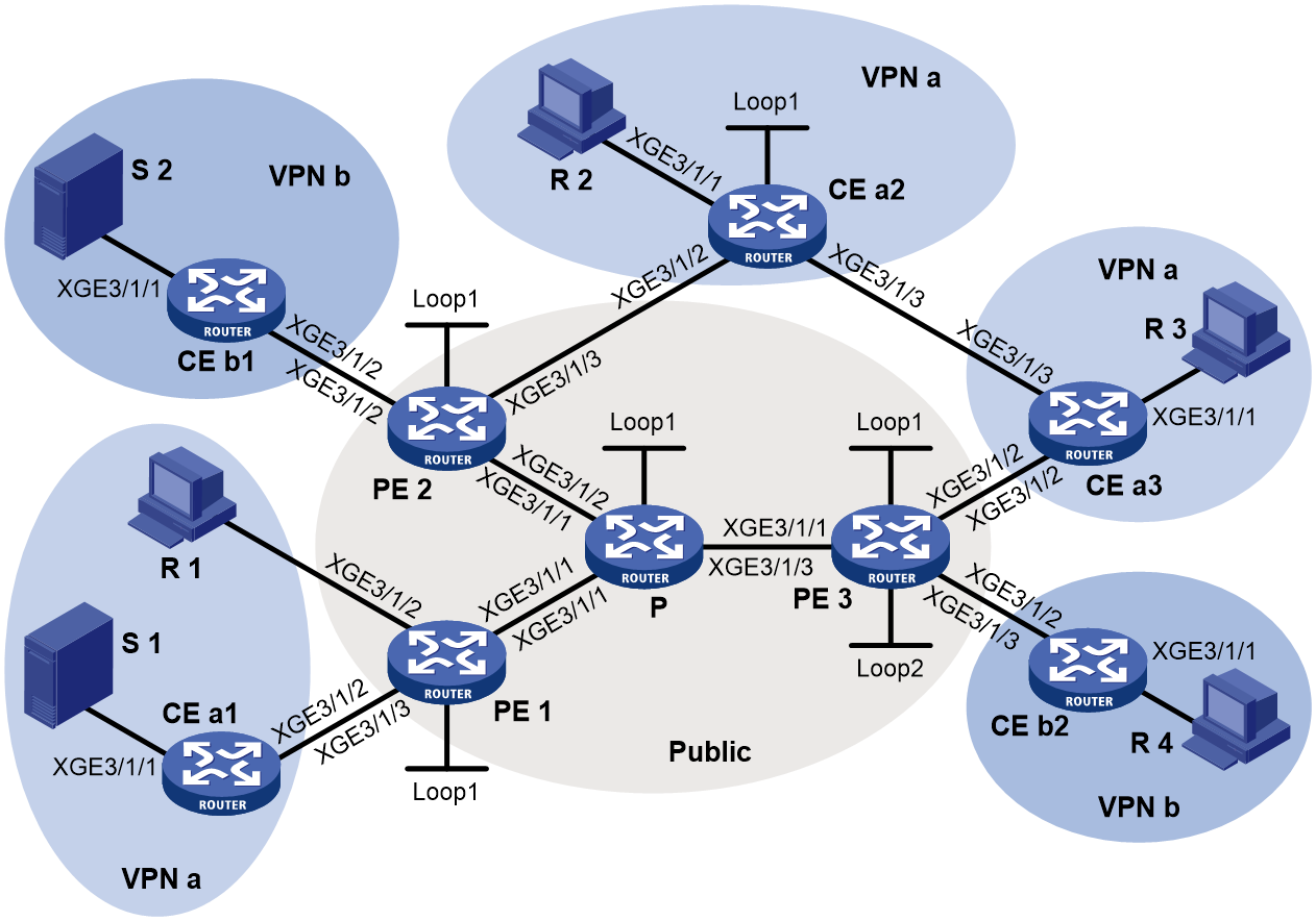
Table 3 Interface and IP address assignment
|
Device |
Interface |
IP address |
Device |
Interface |
IP address |
|
S 1 |
— |
10.110.7.2/24 |
PE 3 |
XGE3/1/1 |
192.168.8.1/24 |
|
S 2 |
— |
10.110.8.2/24 |
PE 3 |
XGE3/1/2 |
10.110.5.1/24 |
|
R 1 |
— |
10.110.1.2/24 |
PE 3 |
XGE3/1/3 |
10.110.6.1/24 |
|
R 2 |
— |
10.110.9.2/24 |
PE 3 |
Loop1 |
1.1.1.3/32 |
|
R 3 |
— |
10.110.10.2/24 |
PE 3 |
Loop2 |
33.33.33.33/32 |
|
R 4 |
— |
10.110.11.2/24 |
CE a1 |
XGE3/1/1 |
10.110.7.1/24 |
|
P |
XGE3/1/1 |
192.168.6.2/24 |
CE a1 |
XGE3/1/2 |
10.110.2.2/24 |
|
P |
XGE3/1/2 |
192.168.7.2/24 |
CE a2 |
XGE3/1/1 |
10.110.9.1/24 |
|
P |
XGE3/1/3 |
192.168.8.2/24 |
CE a2 |
XGE3/1/2 |
10.110.4.2/24 |
|
P |
Loop1 |
2.2.2.2/32 |
CE a2 |
XGE3/1/3 |
10.110.12.1/24 |
|
PE 1 |
XGE3/1/1 |
192.168.6.1/24 |
CE a2 |
Loop1 |
22.22.22.22/32 |
|
PE 1 |
XGE3/1/2 |
10.110.1.1/24 |
CE a3 |
XGE3/1/1 |
10.110.10.1/24 |
|
PE 1 |
XGE3/1/3 |
10.110.2.1/24 |
CE a3 |
XGE3/1/2 |
10.110.5.2/24 |
|
PE 1 |
Loop1 |
1.1.1.1/32 |
CE a3 |
XGE3/1/3 |
10.110.12.2/24 |
|
PE 2 |
XGE3/1/1 |
192.168.7.1/24 |
CE b1 |
XGE3/1/1 |
10.110.8.1/24 |
|
PE 2 |
XGE3/1/2 |
10.110.3.1/24 |
CE b1 |
XGE3/1/2 |
10.110.3.2/24 |
|
PE 2 |
XGE3/1/3 |
10.110.4.1/24 |
CE b2 |
XGE3/1/1 |
10.110.11.1/24 |
|
PE 2 |
Loop1 |
1.1.1.2/32 |
CE b2 |
XGE3/1/2 |
10.110.6.2/24 |
Procedure
1. Configure PE 1:
# Configure a global router ID.
<PE1> system-view
[PE1] router id 1.1.1.1
# Configure an LSR ID, and enable MPLS LDP and mLDP P2MP globally.
[PE1] mpls lsr-id 1.1.1.1
[PE1] mpls ldp
[PE1-ldp] mldp p2mp
[PE1-ldp] quit
# Create a VPN instance named a, and configure an RD and route targets for the VPN instance.
[PE1] ip vpn-instance a
[PE1-vpn-instance-a] route-distinguisher 100:1
[PE1-vpn-instance-a] vpn-target 100:1 export-extcommunity
[PE1-vpn-instance-a] vpn-target 100:1 import-extcommunity
[PE1-vpn-instance-a] quit
# Enable IP multicast routing in VPN instance a.
[PE1] multicast routing vpn-instance a
[PE1-mrib-a] quit
# Create an mLDP-based MVPN for VPN instance a.
[PE1] multicast-vpn vpn-instance a mode mldp
# Create an MVPN IPv4 address family for VPN instance a.
[PE1-mvpn-vpn-instance-a] address-family ipv4
# Specify the MVPN source interface for VPN instance a.
[PE1-mvpn-vpn-instance-a-ipv4] source loopback 1
# Enable dynamic inclusive tunnel creation and dynamic selective tunnel creation for VPN instance a.
[PE1-mvpn-vpn-instance-a-ipv4] inclusive-tunnel dynamic
[PE1-mvpn-vpn-instance-a-ipv4] selective-tunnel dynamic
[PE1-mvpn-vpn-instance-a-ipv4] quit
[PE1-mvpn-vpn-instance-a] quit
# Assign an IP address to Ten-GigabitEthernet 3/1/1, and enable MPLS and IPv4 LDP on Ten-GigabitEthernet 3/1/1.
[PE1] interface ten-gigabitethernet 3/1/1
[PE1-Ten-GigabitEthernet3/1/1] ip address 192.168.6.1 24
[PE1-Ten-GigabitEthernet3/1/1] mpls enable
[PE1-Ten-GigabitEthernet3/1/1] mpls ldp enable
[PE1-Ten-GigabitEthernet3/1/1] quit
# Associate Ten-GigabitEthernet 3/1/2 with VPN instance a, assign an IP address to the interface, and enable IGMP on the interface.
[PE1] interface ten-gigabitethernet 3/1/2
[PE1-Ten-GigabitEthernet3/1/2] ip binding vpn-instance a
[PE1-Ten-GigabitEthernet3/1/2] ip address 10.110.1.1 24
[PE1-Ten-GigabitEthernet3/1/2] igmp enable
[PE1-Ten-GigabitEthernet3/1/2] quit
# Associate Ten-GigabitEthernet 3/1/3 with VPN instance a, assign an IP address to the interface, and enable PIM-SM on the interface.
[PE1] interface ten-gigabitethernet 3/1/3
[PE1-Ten-GigabitEthernet3/1/3] ip binding vpn-instance a
[PE1-Ten-GigabitEthernet3/1/3] ip address 10.110.2.1 24
[PE1-Ten-GigabitEthernet3/1/3] pim sm
[PE1-Ten-GigabitEthernet3/1/3] quit
# Assign an IP address to Loopback 1.
[PE1] interface loopback 1
[PE1-LoopBack1] ip address 1.1.1.1 32
[PE1-LoopBack1] quit
# Configure BGP.
[PE1] bgp 100
[PE1-bgp-default] peer 1.1.1.2 as-number 100
[PE1-bgp-default] peer 1.1.1.2 connect-interface loopback 1
[PE1-bgp-default] peer 1.1.1.3 as-number 100
[PE1-bgp-default] peer 1.1.1.3 connect-interface loopback 1
[PE1-bgp-default] address-family ipv4 mvpn
[PE1-bgp-default-mvpn] peer 1.1.1.2 enable
[PE1-bgp-default-mvpn] peer 1.1.1.3 enable
[PE1-bgp-default-mvpn] quit
[PE1-bgp-default] address-family vpnv4
[PE1-bgp-default-vpnv4] mvpn-advertise-rt-import
[PE1-bgp-default-vpnv4] peer 1.1.1.2 enable
[PE1-bgp-default-vpnv4] peer 1.1.1.3 enable
[PE1-bgp-default-vpnv4] quit
[PE1–bgp-default] ip vpn-instance a
[PE1-bgp-default-a] address-family ipv4 unicast
[PE1-bgp-default-ipv4-a] import-route rip 2
[PE1-bgp-default-ipv4-a] import-route direct
[PE1-bgp-default-ipv4-a] quit
[PE1-bgp-default-a] quit
[PE1–bgp-default] quit
# Configure OSPF.
[PE1] ospf 1
[PE1-ospf-1] area 0.0.0.0
[PE1-ospf-1-area-0.0.0.0] network 1.1.1.1 0.0.0.0
[PE1-ospf-1-area-0.0.0.0] network 192.168.6.0 0.0.0.255
[PE1-ospf-1-area-0.0.0.0] quit
[PE1-ospf-1] quit
# Configure RIP.
[PE1] rip 2 vpn-instance a
[PE1-rip-2] network 10.110.1.0 0.0.0.255
[PE1-rip-2] network 10.110.2.0 0.0.0.255
[PE1-rip-2] import-route bgp
[PE1-rip-2] quit
2. Configure PE 2:
# Configure a global router ID.
<PE2> system-view
[PE2] router id 1.1.1.2
# Configure an LSR ID, and enable MPLS LDP and mLDP P2MP globally.
[PE2] mpls lsr-id 1.1.1.2
[PE2] mpls ldp
[PE2-ldp] mldp p2mp
[PE2-ldp] quit
# Create a VPN instance named b, and configure an RD and route targets for the VPN instance.
[PE2] ip vpn-instance b
[PE2-vpn-instance-b] route-distinguisher 200:1
[PE2-vpn-instance-b] vpn-target 200:1 export-extcommunity
[PE2-vpn-instance-b] vpn-target 200:1 import-extcommunity
[PE2-vpn-instance-b] quit
# Enable IP multicast routing for VPN instance b.
[PE2] multicast routing vpn-instance a
[PE2-mrib-a] quit
# Create an mLDP-based MVPN for VPN instance b.
[PE2] multicast-vpn vpn-instance b mode mldp
# Create an MVPN IPv4 address family for VPN instance b.
[PE2-mvpn-vpn-instance-b] address-family ipv4
# Specify the MVPN source interface for VPN instance b.
[PE2-mvpn-vpn-instance-b-ipv4] source loopback 1
# Enable dynamic inclusive tunnel creation and dynamic selective tunnel creation for VPN instance b.
[PE2-mvpn-vpn-instance-b-ipv4] inclusive-tunnel dynamic
[PE2-mvpn-vpn-instance-b-ipv4] selective-tunnel dynamic
[PE2-mvpn-vpn-instance-b-ipv4] quit
[PE2-mvpn-vpn-instance-b] quit
# Create a VPN instance named a, and configure an RD and route targets for the VPN instance.
[PE2] ip vpn-instance a
[PE2-vpn-instance-a] route-distinguisher 100:1
[PE2-vpn-instance-a] vpn-target 100:1 export-extcommunity
[PE2-vpn-instance-a] vpn-target 100:1 import-extcommunity
[PE2-vpn-instance-a] quit
# Enable IP multicast routing for VPN instance a.
[PE2] multicast routing vpn-instance a
[PE2-mrib-a] quit
# Create an mLDP-based MVPN for VPN instance a.
[PE2] multicast-vpn vpn-instance a mode mldp
# Create an MVPN IPv4 address family for VPN instance a.
[PE2-mvpn-vpn-instance-a] address-family ipv4
# Specify the MVPN source interface for VPN instance a.
[PE2-mvpn-vpn-instance-a-ipv4] source loopback 1
[PE2-mvpn-vpn-instance-a-ipv4] quit
[PE2-mvpn-vpn-instance-a] quit
# Assign an IP address to Ten-GigabitEthernet 3/1/1, and enable MPLS and IPv4 LDP on the interface.
[PE2] interface ten-gigabitethernet 3/1/1
[PE2-Ten-GigabitEthernet3/1/1] ip address 192.168.7.1 24
[PE2-Ten-GigabitEthernet3/1/1] mpls enable
[PE2-Ten-GigabitEthernet3/1/1] mpls ldp enable
[PE2-Ten-GigabitEthernet3/1/1] quit
# Associate Ten-GigabitEthernet 3/1/2 with VPN instance b, assign an IP address to the interface, and enable PIM-SM on the interface.
[PE2] interface ten-gigabitethernet 3/1/2
[PE2-Ten-GigabitEthernet3/1/2] ip binding vpn-instance b
[PE2-Ten-GigabitEthernet3/1/2] ip address 10.110.3.1 24
[PE2-Ten-GigabitEthernet3/1/2] pim sm
[PE2-Ten-GigabitEthernet3/1/2] quit
# Associate Ten-GigabitEthernet 3/1/3 with VPN instance a, assign an IP address to the interface, and enable PIM-SM on the interface.
[PE2] interface ten-gigabitethernet 3/1/3
[PE2-Ten-GigabitEthernet3/1/3] ip binding vpn-instance a
[PE2-Ten-GigabitEthernet3/1/3] ip address 10.110.4.1 24
[PE2-Ten-GigabitEthernet3/1/3] pim sm
[PE2-Ten-GigabitEthernet3/1/3] quit
# Assign an IP address to Loopback 1.
[PE2] interface loopback 1
[PE2-LoopBack1] ip address 1.1.1.2 32
[PE2-LoopBack1] quit
# Configure BGP.
[PE2] bgp 100
[PE2-bgp-default] peer 1.1.1.1 as-number 100
[PE2-bgp-default] peer 1.1.1.1 connect-interface loopback 1
[PE2-bgp-default] peer 1.1.1.3 as-number 100
[PE2-bgp-default] peer 1.1.1.3 connect-interface loopback 1
[PE2-bgp-default] address-family ipv4 mvpn
[PE2-bgp-default-mvpn] peer 1.1.1.1 enable
[PE2-bgp-default-mvpn] peer 1.1.1.3 enable
[PE2-bgp-default-mvpn] quit
[PE2-bgp-default] address-family vpnv4
[PE2-bgp-default-vpnv4] mvpn-advertise-rt-import
[PE2-bgp-default-vpnv4] peer 1.1.1.1 enable
[PE2-bgp-default-vpnv4] peer 1.1.1.3 enable
[PE2-bgp-default-vpnv4] quit
[PE2–bgp-default] ip vpn-instance a
[PE2-bgp-default-a] address-family ipv4 unicast
[PE2-bgp-default-ipv4-a] import-route rip 2
[PE2-bgp-default-ipv4-a] import-route direct
[PE2-bgp-default-ipv4-a] quit
[PE2-bgp-default-a] quit
[PE2–bgp-default] ip vpn-instance b
[PE2-bgp-default-b] address-family ipv4 unicast
[PE2-bgp-default-ipv4-b] import-route rip 3
[PE2-bgp-default-ipv4-b] import-route direct
[PE2-bgp-default-ipv4-b] quit
[PE2-bgp-default-b] quit
[PE2–bgp-default] quit
# Configure OSPF.
[PE2] ospf 1
[PE2-ospf-1] area 0.0.0.0
[PE2-ospf-1-area-0.0.0.0] network 1.1.1.2 0.0.0.0
[PE2-ospf-1-area-0.0.0.0] network 192.168.7.0 0.0.0.255
[PE2-ospf-1-area-0.0.0.0] quit
[PE2-ospf-1] quit
# Configure RIP.
[PE2] rip 2 vpn-instance a
[PE2-rip-2] network 10.110.4.0 0.0.0.255
[PE2-rip-2] import-route bgp
[PE2-rip-2] quit
[PE2] rip 3 vpn-instance b
[PE2-rip-3] network 10.110.3.0 0.0.0.255
[PE2-rip-3] import-route bgp
[PE2-rip-3] quit
3. Configure PE 3:
# Configure a global router ID.
<PE3> system-view
[PE3] router id 1.1.1.3
# Configure an LSR ID, and enable MPLS LDP and mLDP P2MP globally.
[PE3] mpls lsr-id 1.1.1.3
[PE3] mpls ldp
[PE3-ldp] mldp p2mp
[PE3-ldp] quit
# Create a VPN instance named a, and configure an RD and route targets for the VPN instance.
[PE3] ip vpn-instance a
[PE3-vpn-instance-a] route-distinguisher 100:1
[PE3-vpn-instance-a] vpn-target 100:1 export-extcommunity
[PE3-vpn-instance-a] vpn-target 100:1 import-extcommunity
[PE3-vpn-instance-a] quit
# Enable IP multicast routing for VPN instance a.
[PE3] multicast routing vpn-instance a
[PE3-mrib-a] quit
# Create an mLDP-based MVPN for VPN instance a.
[PE3] multicast-vpn vpn-instance a mode mldp
# Create an MVPN IPv4 address family for VPN instance a.
[PE3-mvpn-vpn-instance-a] address-family ipv4
# Specify the MVPN source interface for VPN instance a.
[PE3-mvpn-vpn-instance-a-ipv4] source loopback 1
[PE3-mvpn-vpn-instance-a-ipv4] quit
[PE3-mvpn-vpn-instance-a] quit
# Create a VPN instance named b, and configure an RD and route targets for the VPN instance.
[PE3] ip vpn-instance b
[PE3-vpn-instance-b] route-distinguisher 200:1
[PE3-vpn-instance-b] vpn-target 200:1 export-extcommunity
[PE3-vpn-instance-b] vpn-target 200:1 import-extcommunity
[PE3-vpn-instance-b] quit
# Enable IP multicast routing for VPN instance b.
[PE3] multicast routing vpn-instance b
[PE3-mrib-b] quit
# Create an mLDP-based MVPN for VPN instance b.
[PE3] multicast-vpn vpn-instance b mode mldp
# Create an MVPN IPv4 address family for VPN instance b.
[PE3-mvpn-vpn-instance-b] address-family ipv4
# Specify the MVPN source interface for VPN instance b.
[PE3-mvpn-vpn-instance-b-ipv4] source loopback 1
[PE3-mvpn-vpn-instance-b-ipv4] quit
[PE3-mvpn-vpn-instance-b] quit
# Assign an IP address to Ten-GigabitEthernet 3/1/1, and enable MPLS and IPv4 LDP on the interface.
[PE3] interface ten-gigabitethernet 3/1/1
[PE3-Ten-GigabitEthernet3/1/1] ip address 192.168.8.1 24
[PE3-Ten-GigabitEthernet3/1/1] mpls enable
[PE3-Ten-GigabitEthernet3/1/1] mpls ldp enable
[PE3-Ten-GigabitEthernet3/1/1] quit
# Associate Ten-GigabitEthernet 3/1/2 with VPN instance a, assign an IP address to the interface, and enable PIM-SM on the interface.
[PE3] interface ten-gigabitethernet 3/1/2
[PE3-Ten-GigabitEthernet3/1/2] ip binding vpn-instance a
[PE3-Ten-GigabitEthernet3/1/2] ip address 10.110.5.1 24
[PE3-Ten-GigabitEthernet3/1/2] pim sm
[PE3-Ten-GigabitEthernet3/1/2] quit
# Associate Ten-GigabitEthernet 3/1/3 with VPN instance b, assign an IP address to the interface, and enable PIM-SM on the interface.
[PE3] interface ten-gigabitethernet 3/1/3
[PE3-Ten-GigabitEthernet3/1/3] ip binding vpn-instance b
[PE3-Ten-GigabitEthernet3/1/3] ip address 10.110.6.1 24
[PE3-Ten-GigabitEthernet3/1/3] pim sm
[PE3-Ten-GigabitEthernet3/1/3] quit
# Assign an IP address to Loopback 1.
[PE3] interface loopback 1
[PE3-LoopBack1] ip address 1.1.1.3 32
[PE3-LoopBack1] quit
# Associate Loopback 2 with VPN instance b, assign an IP address to the interface, and enable PIM-SM on the interface.
[PE3] interface loopback 2
[PE3-LoopBack2] ip binding vpn-instance b
[PE3-LoopBack2] ip address 33.33.33.33 32
[PE3-LoopBack2] pim sm
[PE3-LoopBack2] quit
# Configure Loopback 2 as a C-BSR and a C-RP.
[PE3] pim vpn-instance b
[PE3-pim-b] c-bsr 33.33.33.33
[PE3-pim-b] c-rp 33.33.33.33
[PE3-pim-b] quit
# Configure BGP.
[PE3] bgp 100
[PE3-bgp-default] peer 1.1.1.1 as-number 100
[PE3-bgp-default] peer 1.1.1.1 connect-interface loopback 1
[PE3-bgp-default] peer 1.1.1.2 as-number 100
[PE3-bgp-default] peer 1.1.1.2 connect-interface loopback 1
[PE3-bgp-default] address-family ipv4 mvpn
[PE3-bgp-default-mvpn] peer 1.1.1.1 enable
[PE3-bgp-default-mvpn] peer 1.1.1.2 enable
[PE3-bgp-default-mvpn]quit
[PE3-bgp-default] address-family vpnv4
[PE3-bgp-default-vpnv4] mvpn-advertise-rt-import
[PE3-bgp-default-vpnv4] peer 1.1.1.1 enable
[PE3-bgp-default-vpnv4] peer 1.1.1.2 enable
[PE3-bgp-default-vpnv4] quit
[PE3–bgp-default] ip vpn-instance a
[PE3-bgp-default-a] address-family ipv4 unicast
[PE3-bgp-default-ipv4-a] import-route rip 2
[PE3-bgp-default-ipv4-a] import-route direct
[PE3-bgp-default-ipv4-a] quit
[PE3-bgp-default-a] quit
[PE3–bgp-default] ip vpn-instance b
[PE3-bgp-default-b] address-family ipv4 unicast
[PE3-bgp-default-ipv4-b] import-route rip 3
[PE3-bgp-default-ipv4-b] import-route direct
[PE3-bgp-default-ipv4-b] quit
[PE3-bgp-default-b] quit
[PE3–bgp-default] quit
# Configure OSPF.
[PE3] ospf 1
[PE3-ospf-1] area 0.0.0.0
[PE3-ospf-1-area-0.0.0.0] network 1.1.1.3 0.0.0.0
[PE3-ospf-1-area-0.0.0.0] network 192.168.8.0 0.0.0.255
[PE3-ospf-1-area-0.0.0.0] quit
[PE3-ospf-1] quit
# Configure RIP.
[PE3] rip 2 vpn-instance a
[PE3-rip-2] network 10.110.5.0 0.0.0.255
[PE3-rip-2] import-route bgp
[PE3-rip-2] quit
[PE3] rip 3 vpn-instance b
[PE3-rip-3] network 10.110.6.0 0.0.0.255
[PE3-rip-3] network 33.33.33.33 0.0.0.0
[PE3-rip-3] import-route bgp
[PE3-rip-3] quit
4. Configure P:
# Configure an LSR ID, and enable MPLS LDP and mLDP P2MP globally.
[P] mpls lsr-id 2.2.2.2
[P] mpls ldp
[P-ldp] mldp p2mp
[P-ldp] quit
# Assign an IP address to Ten-GigabitEthernet 3/1/1, and enable MPLS and IPv4 LDP on the interface.
[P] interface ten-gigabitethernet 3/1/1
[P-Ten-GigabitEthernet3/1/1] ip address 192.168.6.2 24
[P-Ten-GigabitEthernet3/1/1] mpls enable
[P-Ten-GigabitEthernet3/1/1] mpls ldp enable
[P-Ten-GigabitEthernet3/1/1] quit
# Assign an IP address to Ten-GigabitEthernet 3/1/2, and enable MPLS and IPv4 LDP on the interface.
[P] interface ten-gigabitethernet 3/1/2
[P-Ten-GigabitEthernet3/1/2] ip address 192.168.7.2 24
[P-Ten-GigabitEthernet3/1/2] mpls enable
[P-Ten-GigabitEthernet3/1/2] mpls ldp enable
[P-Ten-GigabitEthernet3/1/2] quit
# Assign an IP address to Ten-GigabitEthernet3/1/3, and enable MPLS and IPv4 LDP on the interface.
[P] interface ten-gigabitethernet 3/1/3
[P-Ten-GigabitEthernet3/1/3] ip address 192.168.8.2 24
[P-Ten-GigabitEthernet3/1/3] mpls enable
[P-Ten-GigabitEthernet3/1/3] mpls ldp enable
[P-Ten-GigabitEthernet3/1/3] quit
# Assign an IP address to Loopback 1.
[P] interface loopback 1
[P-LoopBack1] ip address 2.2.2.2 32
[P-LoopBack1] quit
# Configure OSPF.
[P] ospf 1
[P-ospf-1] area 0.0.0.0
[P-ospf-1-area-0.0.0.0] network 2.2.2.2 0.0.0.0
[P-ospf-1-area-0.0.0.0] network 192.168.6.0 0.0.0.255
[P-ospf-1-area-0.0.0.0] network 192.168.7.0 0.0.0.255
[P-ospf-1-area-0.0.0.0] network 192.168.8.0 0.0.0.255
[P-ospf-1-area-0.0.0.0] quit
[P-ospf-1] quit
5. Configure CE a1:
# Enable IP multicast routing.
<CEa1> system-view
[CEa1] multicast routing
[CEa1-mrib] quit
# Assign an IP address to Ten-GigabitEthernet 3/1/1, and enable PIM-SM on the interface.
[CEa1] interface ten-gigabitethernet 3/1/1
[CEa1-Ten-GigabitEthernet3/1/1] ip address 10.110.7.1 24
[CEa1-Ten-GigabitEthernet3/1/1] pim sm
[CEa1-Ten-GigabitEthernet3/1/1] quit
# Assign an IP address to Ten-GigabitEthernet 3/1/2, and enable PIM-SM on the interface.
[CEa1] interface ten-gigabitethernet 3/1/2
[CEa1-Ten-GigabitEthernet3/1/2] ip address 10.110.2.2 24
[CEa1-Ten-GigabitEthernet3/1/2] pim sm
[CEa1-Ten-GigabitEthernet3/1/2] quit
# Configure RIP.
[CEa1] rip 2
[CEa1-rip-2] network 10.110.2.0 0.0.0.255
[CEa1-rip-2] network 10.110.7.0 0.0.0.255
[CEa1-rip-2] quit
6. Configure CE b1:
# Enable IP multicast routing.
<CEb1> system-view
[CEb1] multicast routing
[CEb1-mrib] quit
# Assign an IP address to Ten-GigabitEthernet 3/1/1, and enable PIM-SM on the interface.
[CEb1] interface ten-gigabitethernet 3/1/1
[CEb1-Ten-GigabitEthernet3/1/1] ip address 10.110.8.1 24
[CEb1-Ten-GigabitEthernet3/1/1] pim sm
[CEb1-Ten-GigabitEthernet3/1/1] quit
# Assign an IP address to Ten-GigabitEthernet 3/1/2, and enable PIM-SM on the interface.
[CEb1] interface ten-gigabitethernet 3/1/2
[CEb1-Ten-GigabitEthernet3/1/2] ip address 10.110.3.2 24
[CEb1-Ten-GigabitEthernet3/1/2] pim sm
[CEb1-Ten-GigabitEthernet3/1/2] quit
# Configure RIP.
[CEb1] rip 3
[CEb1-rip-3] network 10.110.3.0 0.0.0.255
[CEb1-rip-3] network 10.110.8.0 0.0.0.255
[CEb1-rip-2] quit
7. Configure CE a2:
# Enable IP multicast routing.
<CEa2> system-view
[CEa2] multicast routing
[CEa2-mrib] quit
# Assign an IP address to Ten-GigabitEthernet 3/1/1, and enable IGMP on the interface.
[CEa2] interface ten-gigabitethernet 3/1/1
[CEa2-Ten-GigabitEthernet3/1/1] ip address 10.110.9.1 24
[CEa2-Ten-GigabitEthernet3/1/1] igmp enable
[CEa2-Ten-GigabitEthernet3/1/1] quit
# Assign an IP address to Ten-GigabitEthernet 3/1/2, and enable PIM-SM on the interface.
[CEa2] interface ten-gigabitethernet 3/1/2
[CEa2-Ten-GigabitEthernet3/1/2] ip address 10.110.4.2 24
[CEa2-Ten-GigabitEthernet3/1/2] pim sm
[CEa2-Ten-GigabitEthernet3/1/2] quit
# Assign an IP address to Ten-GigabitEthernet 3/1/3, and enable PIM-SM on the interface.
[CEa2] interface ten-gigabitethernet 3/1/3
[CEa2-Ten-GigabitEthernet3/1/3] ip address 10.110.12.1 24
[CEa2-Ten-GigabitEthernet3/1/3] pim sm
[CEa2-Ten-GigabitEthernet3/1/3] quit
# Assign an IP address to Loopback 1, and enable PIM-SM on the interface.
[CEa2] interface loopback 1
[CEa2-LoopBack1] ip address 22.22.22.22 32
[CEa2-LoopBack1] pim sm
[CEa2-LoopBack1] quit
# Configure Loopback 1 as a C-BSR and a C-RP.
[CEa2] pim
[CEa2-pim] c-bsr 22.22.22.22
[CEa2-pim] c-rp 22.22.22.22
[CEa2-pim] quit
# Configure MSDP.
[CEa2] msdp
[CEa2-msdp] peer 10.110.4.1 connect-interface ten-gigabitethernet 3/1/2
[CEa2-msdp] quit
# Configure RIP.
[CEa2] rip 2
[CEa2-rip-2] network 10.110.4.0 0.0.0.255
[CEa2-rip-2] network 10.110.9.0 0.0.0.255
[CEa2-rip-2] network 10.110.12.0 0.0.0.255
[CEa2-rip-2] network 22.22.22.22 0.0.0.0
[CEa2-rip-2] quit
8. Configure CE a3:
# Enable IP multicast routing.
<CEa3> system-view
[CEa3] multicast routing
[CEa3-mrib] quit
# Assign an IP address to Ten-GigabitEthernet 3/1/1, and enable IGMP on the interface.
[CEa3] interface ten-gigabitethernet 3/1/1
[CEa3-Ten-GigabitEthernet3/1/1] ip address 10.110.10.1 24
[CEa3-Ten-GigabitEthernet3/1/1] igmp enable
[CEa3-Ten-GigabitEthernet3/1/1] quit
# Assign an IP address to Ten-GigabitEthernet 3/1/2, and enable PIM-SM on the interface.
[CEa3] interface ten-gigabitethernet 3/1/2
[CEa3-Ten-GigabitEthernet3/1/2] ip address 10.110.5.2 24
[CEa3-Ten-GigabitEthernet3/1/2] pim sm
[CEa3-Ten-GigabitEthernet3/1/2] quit
# Assign an IP address to Ten-GigabitEthernet 3/1/3, and enable PIM-SM on the interface.
[CEa3] interface ten-gigabitethernet 3/1/3
[CEa3-Ten-GigabitEthernet3/1/3] ip address 10.110.12.2 24
[CEa3-Ten-GigabitEthernet3/1/3] pim sm
[CEa3-Ten-GigabitEthernet3/1/3] quit
# Configure RIP.
[CEa3] rip 2
[CEa3-rip-2] network 10.110.5.0 0.0.0.255
[CEa3-rip-2] network 10.110.10.0 0.0.0.255
[CEa3-rip-2] network 10.110.12.0 0.0.0.255
[CEa3-rip-2] quit
9. Configure CE b2:
# Enable IP multicast routing.
<CEb2> system-view
[CEb2] multicast routing
[CEb2-mrib] quit
# Assign an IP address to Ten-GigabitEthernet 3/1/1, and enable IGMP on the interface.
[CEb2] interface ten-gigabitethernet 3/1/1
[CEb2-Ten-GigabitEthernet3/1/1] ip address 10.110.11.1 24
[CEb2-Ten-GigabitEthernet3/1/1] igmp enable
[CEb2-Ten-GigabitEthernet3/1/1] quit
# Assign an IP address to Ten-GigabitEthernet 3/1/2, and enable PIM-SM on the interface.
[CEb2] interface ten-gigabitethernet 3/1/2
[CEb2-Ten-GigabitEthernet3/1/2] ip address 10.110.6.2 24
[CEb2-Ten-GigabitEthernet3/1/2] pim sm
[CEb2-Ten-GigabitEthernet3/1/2] quit
# Configure RIP.
[CEb2] rip 3
[CEb2-rip-3] network 10.110.6.0 0.0.0.255
[CEb2-rip-3] network 10.110.11.0 0.0.0.255
[CEb2-rip-2] quit
Verifying the configuration
# Display information about the mLDP inclusive tunnel for VPN instance a on PE 1.
[PE1] display multicast-vpn vpn-instance a inclusive-tunnel local
Tunnel interface: LSPVOif0
Tunnel identifier: mLDP P2MP <0xe4000000>
Tunnel state: Up
Opaque value: 0x010004e4000000
Root: 1.1.1.1 (local)
Leafs:
1: 1.1.1.2
2: 1.1.1.3
# Display information about mLDP selective tunnels for VPN instance a on PE 1.
[PE1]display multicast-vpn vpn-instance a selective-tunnel local
Total 1 selective tunnel in using
Total 0 selective tunnel in creating
Tunnel interface: LSPVOif1
Tunnel identifier: mLDP P2MP <0xe4000001>
Tunnel state: Up
Opaque value: 0x010004e4000001
Root: 1.1.1.1 (local)
# Display C-multicast A-D route information for VPN instance a on PE 1.
[PE1] display multicast-vpn vpn-instance a c-multicast routing-table
Total 0 (*, G) entry; 1 (S, G) entry
(10.110.7.2, 225.0.0.1)
CreateTime: 02:54:43
Tunnel Information: LSPVOif1
# Display information about the mLDP inclusive tunnel for VPN instance a on PE 2.
[PE2] display multicast-vpn vpn-instance a inclusive-tunnel remote
Tunnel interface: --
Tunnel identifier: mLDP P2MP <0xe4000000>
Tunnel state: --
Opaque value: 0x010004e4000000
Root: 1.1.1.1
Leaf:
1: 1.1.1.2 (local)
# Display information about mLDP selective tunnels for VPN instance a on PE 2.
[PE2] display multicast-vpn vpn-instance a selective-tunnel remote
Tunnel interface: --
Tunnel identifier: mLDP P2MP <0xe4000001>
Tunnel state: --
Opaque value: 0x010004e4000001
Root: 1.1.1.1
Leaf:
1: 1.1.1.2 (local)
# Display information about the mLDP inclusive tunnel for VPN instance b on PE 2.
[PE2] display multicast-vpn vpn-instance b inclusive-tunnel local
Tunnel interface: LSPVOif0
Tunnel identifier: mLDP P2MP <0xe4000000>
Tunnel state: Up
Opaque value: 0x010004e4000000
Root: 1.1.1.2 (local)
Leafs:
1: 1.1.1.1
2: 1.1.1.3
# Display information about mLDP selective tunnels for VPN instance b on PE 2.
[PE2] display multicast-vpn vpn-instance b selective-tunnel local
Total 1 selective tunnel in using
Total 0 selective tunnel in creating
Tunnel interface: LSPVOif1
Tunnel identifier: mLDP P2MP <0xe4000001>
Tunnel state: Up
Opaque value: 0x010004e4000001
Root: 1.1.1.2 (local)
# Display C-multicast A-D route information for VPN instance b on PE 2.
[PE2] display multicast-vpn vpn-instance b c-multicast routing-table
Total 0 (*, G) entry; 1 (S, G) entry
(10.110.8.2, 225.0.0.2)
CreateTime: 02:54:43
Tunnel Information: LSPVOif1
# Display information about the mLDP inclusive tunnel for VPN instance b on PE 3.
[PE3] display multicast-vpn vpn-instance b inclusive-tunnel remote
Tunnel interface: --
Tunnel identifier: mLDP P2MP <0xe4000000>
Tunnel state: --
Opaque value: 0x010004e4000000
Root: 1.1.1.2
Leaf:
1: 1.1.1.3 (local)
# Display information about mLDP selective tunnels for VPN instance b on PE 3.
[PE3] display multicast-vpn vpn-instance b selective-tunnel remote
Tunnel interface: --
Tunnel identifier: mLDP P2MP <0xe4000001>
Tunnel state: --
Opaque value: 0x010004e4000001
Root: 1.1.1.2
Leaf:
1: 1.1.1.3 (local)
Example: Configuring inter-AS option B MDT-based MVPN
Network configuration
As shown in Figure 27, configure inter-AS option B MDT-based MVPN to meet the following requirements:
|
Item |
Network configuration |
|
Multicast sources and receivers |
· In VPN instance a, S 1 is a multicast source, and R 2 is a receiver. · In VPN instance b, S 2 is a multicast source, and R 1 is a receiver. · For VPN instance a, the default group is 232.1.1.1, and the data group range is 232.2.2.0 to 232.2.2.15. They are in the SSM group range. · For VPN instance b, the default group is 232.3.3.3, and the data group range is 232.4.4.0 to 232.4.4.15. They are in the SSM group range. |
|
VPN instances to which PE interfaces belong |
· PE 1: Ten-GigabitEthernet 3/1/2 belongs to VPN instance a. Ten-GigabitEthernet 3/1/3 belongs to VPN instance b. Ten-GigabitEthernet 3/1/1 and Loopback 1 belong to the public network. · PE 2: Ten-GigabitEthernet 3/1/1, Ten-GigabitEthernet 3/1/2, and Loopback 1 belong to the public network. · PE 3: Ten-GigabitEthernet 3/1/1, Ten-GigabitEthernet 3/1/2, and Loopback 1 belong to the public network. · PE 4: Ten-GigabitEthernet 3/1/2 belongs to VPN instance a. Ten-GigabitEthernet 3/1/3 belongs to VPN instance b. Ten-GigabitEthernet 3/1/1 and Loopback 1 belong to the public network. |
|
Unicast routing protocols and MPLS |
· Configure OSPF in AS 100 and AS 200, and configure OSPF between the PEs and CEs. · Establish IBGP peer connections between PE 1, PE 2, PE 3, and PE 4 on their respective Loopback 1. · Establish EBGP peer connections between Ten-GigabitEthernet 3/1/2 on PE 2 and PE 3. · Configure BGP MDT peer connections between PE 1, PE 2, PE 3, and PE 4 on their respective Loopback 1 and between PE 2 and PE 3 on their respective Ten-GigabitEthernet 3/1/2. · Configure MPLS in AS 100 and AS 200. |
|
IP multicast routing |
· Enable IP multicast routing on P 1 and P 2. · Enable IP multicast routing for the public network on PE 1, PE 2, PE 3, and PE 4. · Enable IP multicast routing for VPN instance a on PE 1 and PE 4. · Enable IP multicast routing for VPN instance b on PE 1 and PE 4. · Enable IP multicast routing on CE a1, CE a2, CE b1, and CE b2. |
|
IGMPv2 |
· Enable IGMPv2 on Ten-GigabitEthernet 3/1/1 of CE a2. · Enable IGMPv2 on Ten-GigabitEthernet 3/1/1 of CE b2. |
|
PIM |
Enable PIM-SSM on the public network and PIM-SM for VPN instances a and b: · Enable PIM-SM on all interfaces of P 1 and P 2. · Enable PIM-SM on all public network interfaces of PE 2 and PE 3. · Enable PIM-SM on all public and private network interfaces of PE 1 and PE 4. · Enable PIM-SM on all interfaces that do not have attached receiver hosts on CE a1, CE a2, CE b1, and CE b2. · Configure Ten-GigabitEthernet 3/1/2 of CE a1 as a C-BSR and a C-RP for VPN instance a to provide services for all multicast groups. · Configure Ten-GigabitEthernet 3/1/2 of CE b1 as a C-BSR and a C-RP for VPN instance b to provide services for all multicast groups. |
|
RPF vector |
Enable the RPF vector feature on PE 1 and PE 4. |
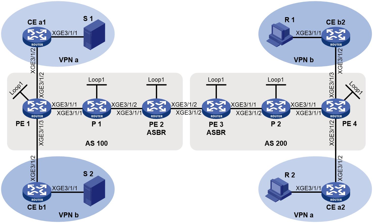
Table 4 Interface and IP address assignment
|
Device |
Interface |
IP address |
Device |
Interface |
IP address |
|
S 1 |
— |
12.1.1.100/24 |
R 1 |
— |
12.4.1.100/24 |
|
S 2 |
— |
12.2.1.100/24 |
R 2 |
— |
12.3.1.100/24 |
|
PE 1 |
XGE3/1/1 |
10.1.1.1/24 |
PE 3 |
XGE3/1/1 |
10.4.1.1/24 |
|
PE 1 |
XGE3/1/2 |
11.1.1.1/24 |
PE 3 |
XGE3/1/2 |
10.3.1.2/24 |
|
PE 1 |
XGE3/1/3 |
11.2.1.1/24 |
PE 3 |
Loop1 |
3.3.3.3/32 |
|
PE 1 |
Loop1 |
1.1.1.1/32 |
PE 4 |
XGE3/1/1 |
10.5.1.2/24 |
|
PE 2 |
XGE3/1/1 |
10.2.1.2/24 |
PE 4 |
XGE3/1/2 |
11.3.1.1/24 |
|
PE 2 |
XGE3/1/2 |
10.3.1.1/24 |
PE 4 |
XGE3/1/3 |
11.4.1.1/24 |
|
PE 2 |
Loop1 |
2.2.2.2/32 |
PE 4 |
Loop1 |
4.4.4.4/24 |
|
P 1 |
XGE3/1/1 |
10.1.1.2/24 |
P 2 |
XGE3/1/1 |
10.5.1.1/24 |
|
P 1 |
XGE3/1/2 |
10.2.1.1/24 |
P 2 |
XGE3/1/2 |
10.4.1.2/24 |
|
P 1 |
Loop1 |
5.5.5.5/32 |
P 2 |
Loop1 |
6.6.6.6/32 |
|
CE a1 |
XGE3/1/1 |
12.1.1.1/24 |
CE b1 |
XGE3/1/1 |
12.2.1.1/24 |
|
CE a1 |
XGE3/1/2 |
11.1.1.2/24 |
CE b1 |
XGE3/1/2 |
11.2.1.2/24 |
|
CE a2 |
XGE3/1/1 |
12.3.1.1/24 |
CE b2 |
XGE3/1/1 |
12.4.1.1/24 |
|
CE a2 |
XGE3/1/2 |
11.3.1.2/24 |
CE b2 |
XGE3/1/2 |
11.4.1.2/24 |
Procedure
1. Configure PE 1:
# Configure a global router ID, and enable IP multicast routing on the public network.
<PE1> system-view
[PE1] router id 1.1.1.1
[PE1] multicast routing
[PE1-mrib] quit
# Configure an LSR ID, and enable LDP globally.
[PE1] mpls lsr-id 1.1.1.1
[PE1] mpls ldp
[PE1-ldp] quit
# Create a VPN instance named a, and configure the RD and route targets for the VPN instance.
[PE1] ip vpn-instance a
[PE1-vpn-instance-a] route-distinguisher 100:1
[PE1-vpn-instance-a] vpn-target 100:1 export-extcommunity
[PE1-vpn-instance-a] vpn-target 100:1 import-extcommunity
[PE1-vpn-instance-a] quit
# Enable IP multicast routing and RPF vector for VPN instance a.
[PE1] multicast routing vpn-instance a
[PE1-mrib-a] rpf proxy vector
[PE1-mrib-a] quit
# Create an MDT-based MVPN for VPN instance a.
[PE1] multicast-vpn vpn-instance a mode mdt
# Create an MVPN IPv4 address family for VPN instance a.
[PE1-mvpn-vpn-instance-a] address-family ipv4
# Specify the default group, the MVPN source interface, and the data group range for VPN instance a.
[PE1-mvpn-vpn-instance-a-ipv4] default-group 232.1.1.1
[PE1-mvpn-vpn-instance-a-ipv4] source loopback 1
[PE1-mvpn-vpn-instance-a-ipv4] data-group 232.2.2.0 28
[PE1-mvpn-vpn-instance-a-ipv4] quit
[PE1-mvpn-vpn-instance-a] quit
# Create a VPN instance named b, and configure the RD and route targets for the VPN instance.
[PE1] ip vpn-instance b
[PE1-vpn-instance-b] route-distinguisher 200:1
[PE1-vpn-instance-b] vpn-target 200:1 export-extcommunity
[PE1-vpn-instance-b] vpn-target 200:1 import-extcommunity
[PE1-vpn-instance-b] quit
# Enable IP multicast routing and RPF vector for VPN instance b.
[PE1] multicast routing vpn-instance b
[PE1-mrib-b] rpf proxy vector
[PE1-mrib-b] quit
# Create an MDT-based MVPN for VPN instance b.
[PE1] multicast-vpn vpn-instance b mode mdt
# Create an MVPN IPv4 address family for VPN instance b.
[PE1-mvpn-vpn-instance-b] address-family ipv4
# Specify the default group, the MVPN source interface, and the data group range for VPN instance b.
[PE1-mvpn-vpn-instance-b-ipv4] default-group 232.3.3.3
[PE1-mvpn-vpn-instance-b-ipv4] source loopback 1
[PE1-mvpn-vpn-instance-b-ipv4] data-group 232.4.4.0 28
[PE1-mvpn-vpn-instance-b-ipv4] quit
[PE1-mvpn-vpn-instance-b] quit
# Assign an IP address to Ten-GigabitEthernet 3/1/1.
[PE1] interface ten-gigabitethernet 3/1/1
[PE1-Ten-GigabitEthernet3/1/1] ip address 10.1.1.1 24
# Enable PIM-SM, MPLS, and IPv4 LDP on Ten-GigabitEthernet 3/1/1.
[PE1-Ten-GigabitEthernet3/1/1] pim sm
[PE1-Ten-GigabitEthernet3/1/1] mpls enable
[PE1-Ten-GigabitEthernet3/1/1] mpls ldp enable
[PE1-Ten-GigabitEthernet3/1/1] quit
# Associate Ten-GigabitEthernet 3/1/2 with VPN instance a.
[PE1] interface ten-gigabitethernet 3/1/2
[PE1-Ten-GigabitEthernet3/1/2] ip binding vpn-instance a
# Assign an IP address to Ten-GigabitEthernet 3/1/2, and enable PIM-SM on the interface.
[PE1-Ten-GigabitEthernet3/1/2] ip address 11.1.1.1 24
[PE1-Ten-GigabitEthernet3/1/2] pim sm
[PE1-Ten-GigabitEthernet3/1/2] quit
# Associate Ten-GigabitEthernet 3/1/3 with VPN instance b.
[PE1] interface ten-gigabitethernet 3/1/3
[PE1-Ten-GigabitEthernet3/1/3] ip binding vpn-instance b
# Assign an IP address to Ten-GigabitEthernet 3/1/3, and enable PIM-SM on the interface.
[PE1-Ten-GigabitEthernet3/1/3] ip address 11.2.1.1 24
[PE1-Ten-GigabitEthernet3/1/3] pim sm
[PE1-Ten-GigabitEthernet3/1/3] quit
# Assign an IP address to Loopback 1, and enable PIM-SM on the interface.
[PE1] interface loopback 1
[PE1-LoopBack1] ip address 1.1.1.1 32
[PE1-LoopBack1] pim sm
[PE1-LoopBack1] quit
# Configure BGP.
[PE1] bgp 100
[PE1-bgp-default] peer 2.2.2.2 as-number 100
[PE1-bgp-default] peer 2.2.2.2 connect-interface loopback 1
[PE1–bgp-default] ip vpn-instance a
[PE1-bgp-default-a] address-family ipv4
[PE1-bgp-default-ipv4-a] import-route ospf 2
[PE1-bgp-default-ipv4-a] import-route direct
[PE1-bgp-default-ipv4-a] quit
[PE1-bgp-default-a] quit
[PE1–bgp-default] ip vpn-instance b
[PE1-bgp-default-b] address-family ipv4
[PE1-bgp-default-ipv4-b] import-route ospf 3
[PE1-bgp-default-ipv4-b] import-route direct
[PE1-bgp-default-ipv4-b] quit
[PE1-bgp-default-b] quit
[PE1–bgp-default] address-family vpnv4
[PE1–bgp-default-vpnv4] peer 2.2.2.2 enable
[PE1–bgp-default-vpnv4] quit
[PE1-bgp-default] address-family ipv4 mdt
[PE1-bgp-default-mdt] peer 2.2.2.2 enable
[PE1-bgp-default-mdt] quit
[PE1–bgp-default] quit
# Configure OSPF.
[PE1] ospf 1
[PE1-ospf-1] area 0.0.0.0
[PE1-ospf-1-area-0.0.0.0] network 1.1.1.1 0.0.0.0
[PE1-ospf-1-area-0.0.0.0] network 10.1.1.0 0.0.0.255
[PE1-ospf-1-area-0.0.0.0] quit
[PE1-ospf-1] quit
# Configure OSPF.
[PE1] ospf 2 vpn-instance a
[PE1-ospf-2] area 0.0.0.0
[PE1-ospf-2-area-0.0.0.0] network 11.1.1.0 0.0.0.255
[PE1-ospf-2-area-0.0.0.0] quit
[PE1-ospf-2] quit
[PE1] ospf 3 vpn-instance b
[PE1-ospf-3] area 0.0.0.0
[PE1-ospf-3-area-0.0.0.0] network 11.2.1.0 0.0.0.255
[PE1-ospf-3-area-0.0.0.0] quit
[PE1-ospf-3] quit
2. Configure PE 2:
# Configure a global router ID, and enable IP multicast routing on the public network.
<PE2> system-view
[PE2] router id 2.2.2.2
[PE2] multicast routing
[PE2-mrib] quit
# Configure an LSR ID, and enable LDP globally.
[PE2] mpls lsr-id 2.2.2.2
[PE2] mpls ldp
[PE2-ldp] quit
# Assign an IP address to Ten-GigabitEthernet 3/1/1.
[PE2] interface ten-gigabitethernet 3/1/1
[PE2-Ten-GigabitEthernet3/1/1] ip address 10.2.1.2 24
# Enable PIM-SM, MPLS, and IPv4 LDP on Ten-GigabitEthernet 3/1/1.
[PE2-Ten-GigabitEthernet3/1/1] pim sm
[PE2-Ten-GigabitEthernet3/1/1] mpls enable
[PE2-Ten-GigabitEthernet3/1/1] mpls ldp enable
[PE2-Ten-GigabitEthernet3/1/1] quit
# Assign an IP address to Ten-GigabitEthernet 3/1/2.
[PE2] interface ten-gigabitethernet 3/1/2
[PE2-Ten-GigabitEthernet3/1/2] ip address 10.3.1.1 24
# Enable PIM-SM and MPLS on Ten-GigabitEthernet 3/1/2.
[PE2-Ten-GigabitEthernet3/1/2] pim sm
[PE2-Ten-GigabitEthernet3/1/2] mpls enable
[PE2-Ten-GigabitEthernet3/1/2] quit
# Assign an IP address to Loopback 1, and enable PIM-SM on the interface.
[PE2] interface loopback 1
[PE2-LoopBack1] ip address 2.2.2.2 32
[PE2-LoopBack1] pim sm
[PE2-LoopBack1] quit
# Configure BGP.
[PE2] bgp 100
[PE2-bgp-default] peer 1.1.1.1 as-number 100
[PE2-bgp-default] peer 1.1.1.1 connect-interface loopback 1
[PE2-bgp-default] peer 10.3.1.2 as-number 200
[PE2-bgp-default] address-family vpnv4
[PE2-bgp-default-vpnv4] undo policy vpn-target
[PE2-bgp-default-vpnv4] peer 1.1.1.1 enable
[PE2-bgp-default-vpnv4] peer 10.3.1.2 enable
[PE2-bgp-default-vpnv4] quit
[PE2-bgp-default] address-family ipv4 mdt
[PE2-bgp-default-mdt] peer 1.1.1.1 enable
[PE2-bgp-default-mdt] peer 10.3.1.2 enable
[PE2-bgp-default-mdt] quit
[PE2–bgp-default] quit
# Configure OSPF.
[PE2] ospf 1
[PE2-ospf-1] area 0.0.0.0
[PE2-ospf-1-area-0.0.0.0] network 2.2.2.2 0.0.0.0
[PE2-ospf-1-area-0.0.0.0] network 10.2.1.0 0.0.0.255
[PE2-ospf-1-area-0.0.0.0] quit
[PE2-ospf-1] quit
3. Configure PE 3:
# Configure a global router ID, and enable IP multicast routing on the public network.
<PE3> system-view
[PE3] router id 3.3.3.3
[PE3] multicast routing
[PE3-mrib] quit
# Configure an LSR ID, and enable LDP globally.
[PE3] mpls lsr-id 3.3.3.3
[PE3] mpls ldp
[PE3-ldp] quit
# Assign an IP address to Ten-GigabitEthernet 3/1/1.
[PE3] interface ten-gigabitethernet 3/1/1
[PE3-Ten-GigabitEthernet3/1/1] ip address 10.4.1.1 24
# Enable PIM-SM, MPLS, and IPv4 LDP on Ten-GigabitEthernet 3/1/1.
[PE3-Ten-GigabitEthernet3/1/1] pim sm
[PE3-Ten-GigabitEthernet3/1/1] mpls enable
[PE3-Ten-GigabitEthernet3/1/1] mpls ldp enable
[PE3-Ten-GigabitEthernet3/1/1] quit
# Assign an IP address to Ten-GigabitEthernet 3/1/2.
[PE3] interface ten-gigabitethernet 3/1/2
[PE3-Ten-GigabitEthernet3/1/2] ip address 10.3.1.2 24
# Enable PIM-SM and MPLS on Ten-GigabitEthernet 3/1/2.
[PE3-Ten-GigabitEthernet3/1/2] pim sm
[PE3-Ten-GigabitEthernet3/1/2] mpls enable
[PE3-Ten-GigabitEthernet3/1/2] quit
# Assign an IP address to Loopback 1, and enable PIM-SM on the interface.
[PE3] interface loopback 1
[PE3-LoopBack1] ip address 3.3.3.3 32
[PE3-LoopBack1] pim sm
[PE3-LoopBack1] quit
# Configure BGP.
[PE3] bgp 200
[PE3-bgp-default] peer 4.4.4.4 as-number 200
[PE3-bgp-default] peer 4.4.4.4 connect-interface loopback 1
[PE3-bgp-default] peer 10.3.1.1 as-number 100
[PE3-bgp-default] address-family vpnv4
[PE3-bgp-default-vpnv4] undo policy vpn-target
[PE3-bgp-default-vpnv4] peer 4.4.4.4 enable
[PE3-bgp-default-vpnv4] peer 10.3.1.1 enable
[PE3-bgp-default-vpnv4] quit
[PE3-bgp-default] address-family ipv4 mdt
[PE3-bgp-default-mdt] peer 4.4.4.4 enable
[PE3-bgp-default-mdt] peer 10.3.1.1 enable
[PE3-bgp-default-mdt] quit
[PE3–bgp-default] quit
# Configure OSPF.
[PE3] ospf 1
[PE3-ospf-1] area 0.0.0.0
[PE3-ospf-1-area-0.0.0.0] network 3.3.3.3 0.0.0.0
[PE3-ospf-1-area-0.0.0.0] network 10.4.1.0 0.0.0.255
[PE3-ospf-1-area-0.0.0.0] quit
[PE3-ospf-1] quit
4. Configure PE 4:
# Configure a global router ID, and enable IP multicast routing on the public network.
<PE4> system-view
[PE4] router id 4.4.4.4
[PE4] multicast routing
[PE4-mrib] quit
# Configure an LSR ID, and enable LDP globally.
[PE4] mpls lsr-id 4.4.4.4
[PE4] mpls ldp
[PE4-ldp] quit
# Create a VPN instance named a, and configure the RD and route targets for the VPN instance.
[PE4] ip vpn-instance a
[PE4-vpn-instance-a] route-distinguisher 100:1
[PE4-vpn-instance-a] vpn-target 100:1 export-extcommunity
[PE4-vpn-instance-a] vpn-target 100:1 import-extcommunity
[PE4-vpn-instance-a] quit
# Enable IP multicast routing and RPF vector for VPN instance a.
[PE4] multicast routing vpn-instance a
[PE4-mrib-a] rpf proxy vector
[PE4-mrib-a] quit
# Create an MDT-based MVPN for VPN instance a.
[PE4] multicast-vpn vpn-instance a mode mdt
# Create an MVPN IPv4 address family for VPN instance a.
[PE4-mvpn-vpn-instance-a] address-family ipv4
# Specify the default group, the MVPN source interface, and the data group range for VPN instance a.
[PE4-mvpn-vpn-instance-a-ipv4] default-group 232.1.1.1
[PE4-mvpn-vpn-instance-a-ipv4] source loopback 1
[PE4-mvpn-vpn-instance-a-ipv4] data-group 232.2.2.0 28
[PE4-mvpn-vpn-instance-a-ipv4] quit
[PE4-mvpn-vpn-instance-a] quit
# Create a VPN instance named b, and configure the RD and route targets for the VPN instance.
[PE4] ip vpn-instance b
[PE4-vpn-instance-b] route-distinguisher 200:1
[PE4-vpn-instance-b] vpn-target 200:1 export-extcommunity
[PE4-vpn-instance-b] vpn-target 200:1 import-extcommunity
[PE4-vpn-instance-b] quit
# Enable IP multicast routing and RPF vector for VPN instance b.
[PE4] multicast routing vpn-instance b
[PE4-mrib-b] rpf proxy vector
[PE4-mrib-b] quit
# Create an MDT-based MVPN for VPN instance b,.
[PE4] multicast-vpn vpn-instance b mode mdt
# Create an MVPN IPv4 address family for VPN instance b.
[PE4-mvpn-vpn-instance-b] address-family ipv4
# Specify the default group, the MVPN source interface, and the data group range for VPN instance b.
[PE4-mvpn-vpn-instance-b-ipv4] default-group 232.3.3.3
[PE4-mvpn-vpn-instance-b-ipv4] source loopback 1
[PE4-mvpn-vpn-instance-b-ipv4] data-group 232.4.4.0 28
[PE4-mvpn-vpn-instance-b-ipv4] quit
[PE4-mvpn-vpn-instance-b] quit
# Assign an IP address to Ten-GigabitEthernet 3/1/1.
[PE4] interface ten-gigabitethernet 3/1/1
[PE4-Ten-GigabitEthernet3/1/1] ip address 10.5.1.2 24
# Enable PIM-SM, MPLS, and IPv4 LDP on Ten-GigabitEthernet 3/1/1.
[PE4-Ten-GigabitEthernet3/1/1] pim sm
[PE4-Ten-GigabitEthernet3/1/1] mpls enable
[PE4-Ten-GigabitEthernet3/1/1] mpls ldp enable
[PE4-Ten-GigabitEthernet3/1/1] quit
# Associate Ten-GigabitEthernet 3/1/2 with VPN instance a.
[PE4] interface ten-gigabitethernet 3/1/2
[PE4-Ten-GigabitEthernet3/1/2] ip binding vpn-instance a
# Assign an IP address to Ten-GigabitEthernet 3/1/2, and enable PIM-SM on the interface.
[PE4-Ten-GigabitEthernet3/1/2] ip address 11.3.1.1 24
[PE4-Ten-GigabitEthernet3/1/2] pim sm
[PE4-Ten-GigabitEthernet3/1/2] quit
# Associate Ten-GigabitEthernet 3/1/3 with VPN instance b.
[PE4] interface ten-gigabitethernet 3/1/3
[PE4-Ten-GigabitEthernet3/1/3] ip binding vpn-instance b
# Assign an IP address to Ten-GigabitEthernet 3/1/3, and enable PIM-SM on the interface.
[PE4-Ten-GigabitEthernet3/1/3] ip address 11.4.1.1 24
[PE4-Ten-GigabitEthernet3/1/3] pim sm
[PE4-Ten-GigabitEthernet3/1/3] quit
# Assign an IP address to Loopback 1, and enable PIM-SM on the interface.
[PE4] interface loopback 1
[PE4-LoopBack1] ip address 4.4.4.4 32
[PE4-LoopBack1] pim sm
[PE4-LoopBack1] quit
# Configure BGP.
[PE4] bgp 200
[PE4-bgp-default] peer 3.3.3.3 as-number 200
[PE4-bgp-default] peer 3.3.3.3 connect-interface loopback 1
[PE4–bgp-default] ip vpn-instance a
[PE4-bgp-default-a] address-family ipv4
[PE4-bgp-default-ipv4-a] import-route ospf 2
[PE4-bgp-default-ipv4-a] import-route direct
[PE4-bgp-default-ipv4-a] quit
[PE4-bgp-default-a] quit
[PE4–bgp-default] ip vpn-instance b
[PE4-bgp-default-b] address-family ipv4
[PE4-bgp-default-ipv4-b] import-route ospf 3
[PE4-bgp-default-ipv4-b] import-route direct
[PE4-bgp-default-ipv4-b] quit
[PE4-bgp-default-b] quit
[PE4–bgp-default] address-family vpnv4
[PE4–bgp-default-vpnv4] peer 3.3.3.3 enable
[PE4–bgp-default-vpnv4] quit
[PE4-bgp-default] address-family ipv4 mdt
[PE4-bgp-default-mdt] peer 3.3.3.3 enable
[PE4-bgp-default-mdt] quit
[PE4–bgp-default] quit
# Configure OSPF.
[PE4] ospf 1
[PE4-ospf-1] area 0.0.0.0
[PE4-ospf-1-area-0.0.0.0] network 4.4.4.4 0.0.0.0
[PE4-ospf-1-area-0.0.0.0] network 10.5.1.0 0.0.0.255
[PE4-ospf-1-area-0.0.0.0] quit
[PE4-ospf-1] quit
[PE4] ospf 2 vpn-instance a
[PE4-ospf-2] area 0.0.0.0
[PE4-ospf-2-area-0.0.0.0] network 11.3.1.0 0.0.0.255
[PE4-ospf-2-area-0.0.0.0] quit
[PE4-ospf-2] quit
[PE4] ospf 3 vpn-instance b
[PE4-ospf-3] area 0.0.0.0
[PE4-ospf-3-area-0.0.0.0] network 11.4.1.0 0.0.0.255
[PE4-ospf-3-area-0.0.0.0] quit
[PE4-ospf-3] quit
5. Configure P 1:
# Enable IP multicast routing on the public network.
<P1> system-view
[P1] multicast routing
[P1-mrib] quit
# Configure an LSR ID, and enable LDP globally.
[P1] mpls lsr-id 5.5.5.5
[P1] mpls ldp
[P1-ldp] quit
# Assign an IP address to Ten-GigabitEthernet 3/1/1.
[P1] interface ten-gigabitethernet 3/1/1
[P1-Ten-GigabitEthernet3/1/1] ip address 10.1.1.2 24
# Enable PIM-SM, MPLS, and IPv4 LDP on Ten-GigabitEthernet 3/1/1.
[P1-Ten-GigabitEthernet3/1/1] pim sm
[P1-Ten-GigabitEthernet3/1/1] mpls enable
[P1-Ten-GigabitEthernet3/1/1] mpls ldp enable
[P1-Ten-GigabitEthernet3/1/1] quit
# Assign an IP address to Ten-GigabitEthernet 3/1/2.
[P1] interface ten-gigabitethernet 3/1/2
[P1-Ten-GigabitEthernet3/1/2] ip address 10.2.1.1 24
# Enable PIM-SM, MPLS, and IPv4 LDP on Ten-GigabitEthernet 3/1/2.
[P1-Ten-GigabitEthernet3/1/2] pim sm
[P1-Ten-GigabitEthernet3/1/2] mpls enable
[P1-Ten-GigabitEthernet3/1/2] mpls ldp enable
[P1-Ten-GigabitEthernet3/1/2] quit
# Assign an IP address to Loopback 1, and enable PIM-SM on the interface.
[P1] interface loopback 1
[P1-LoopBack1] ip address 5.5.5.5 32
[P1-LoopBack1] pim sm
[P1-LoopBack1] quit
# Configure OSPF.
[P1] ospf 1
[P1-ospf-1] area 0.0.0.0
[P1-ospf-1-area-0.0.0.0] network 5.5.5.5 0.0.0.0
[P1-ospf-1-area-0.0.0.0] network 10.1.1.0 0.0.0.255
[P1-ospf-1-area-0.0.0.0] network 10.2.1.0 0.0.0.255
6. Configure P 2:
# Enable IP multicast routing on the public network.
<P2> system-view
[P2] multicast routing
[P2-mrib] quit
# Configure an LSR ID, and enable LDP globally.
[P2] mpls lsr-id 6.6.6.6
[P2] mpls ldp
[P2-ldp] quit
# Assign an IP address to Ten-GigabitEthernet 3/1/1.
[P2] interface ten-gigabitethernet 3/1/1
[P2-Ten-GigabitEthernet3/1/1] ip address 10.5.1.1 24
# Enable PIM-SM, MPLS, and IPv4 LDP on Ten-GigabitEthernet 3/1/1.
[P2-Ten-GigabitEthernet3/1/1] pim sm
[P2-Ten-GigabitEthernet3/1/1] mpls enable
[P2-Ten-GigabitEthernet3/1/1] mpls ldp enable
[P2-Ten-GigabitEthernet3/1/1] quit
# Assign an IP address to Ten-GigabitEthernet 3/1/2.
[P2] interface ten-gigabitethernet 3/1/2
[P2-Ten-GigabitEthernet3/1/2] ip address 10.4.1.2 24
# Enable PIM-SM, MPLS, and IPv4 LDP on Ten-GigabitEthernet 3/1/2.
[P2-Ten-GigabitEthernet3/1/2] pim sm
[P2-Ten-GigabitEthernet3/1/2] mpls enable
[P2-Ten-GigabitEthernet3/1/2] mpls ldp enable
[P2-Ten-GigabitEthernet3/1/2] quit
# Assign an IP address to Loopback 1, and enable PIM-SM on the interface.
[P2] interface loopback 1
[P2-LoopBack1] ip address 6.6.6.6 32
[P2-LoopBack1] pim sm
[P2-LoopBack1] quit
# Configure OSPF.
[P2] ospf 1
[P2-ospf-1] area 0.0.0.0
[P2-ospf-1-area-0.0.0.0] network 6.6.6.6 0.0.0.0
[P2-ospf-1-area-0.0.0.0] network 10.4.1.0 0.0.0.255
[P2-ospf-1-area-0.0.0.0] network 10.5.1.0 0.0.0.255
7. Configure CE a1:
# Enable IP multicast routing.
<CEa1> system-view
[CEa1] multicast routing
[CEa1-mrib] quit
# Assign an IP address to Ten-GigabitEthernet 3/1/1, and enable PIM-SM on the interface.
[CEa1] interface ten-gigabitethernet 3/1/1
[CEa1-Ten-GigabitEthernet3/1/1] ip address 12.1.1.1 24
[CEa1-Ten-GigabitEthernet3/1/1] pim sm
[CEa1-Ten-GigabitEthernet3/1/1] quit
# Assign an IP address to Ten-GigabitEthernet 3/1/2, and enable PIM-SM on the interface.
[CEa1] interface ten-gigabitethernet 3/1/2
[CEa1-Ten-GigabitEthernet3/1/2] ip address 11.1.1.2 24
[CEa1-Ten-GigabitEthernet3/1/2] pim sm
[CEa1-Ten-GigabitEthernet3/1/2] quit
# Configure Ten-GigabitEthernet 3/1/2 as a C-BSR and a C-RP.
[CEa1] pim
[CEa1-pim] c-bsr 11.1.1.2
[CEa1-pim] c-rp 11.1.1.2
[CEa1-pim] quit
# Configure OSPF.
[CEa1] ospf 1
[CEa1-ospf-1] area 0.0.0.0
[CEa1-ospf-1-area-0.0.0.0] network 12.1.1.0 0.0.0.255
[CEa1-ospf-1-area-0.0.0.0] network 11.1.1.0 0.0.0.255
[CEa1-ospf-1-area-0.0.0.0] quit
[CEa1-ospf-1] quit
8. Configure CE b1:
# Enable IP multicast routing.
<CEb1> system-view
[CEb1] multicast routing
[CEb1-mrib] quit
# Assign an IP address to Ten-GigabitEthernet 3/1/1, and enable PIM-SM on the interface.
[CEb1] interface ten-gigabitethernet 3/1/1
[CEb1-Ten-GigabitEthernet3/1/1] ip address 12.2.1.1 24
[CEb1-Ten-GigabitEthernet3/1/1] pim sm
[CEb1-Ten-GigabitEthernet3/1/1] quit
# Assign an IP address to Ten-GigabitEthernet 3/1/2, and enable PIM-SM on the interface.
[CEb1] interface ten-gigabitethernet 3/1/2
[CEb1-Ten-GigabitEthernet3/1/2] ip address 11.2.1.2 24
[CEb1-Ten-GigabitEthernet3/1/2] pim sm
[CEb1-Ten-GigabitEthernet3/1/2] quit
# Configure Ten-GigabitEthernet 3/1/2 as a C-BSR and a C-RP.
[CEb1] pim
[CEb1-pim] c-bsr 11.2.1.2 24
[CEb1-pim] c-rp 11.2.1.2 24
[CEb1-pim] quit
# Configure OSPF.
[CEb1] ospf 1
[CEb1-ospf-1] area 0.0.0.0
[CEb1-ospf-1-area-0.0.0.0] network 12.2.1.0 0.0.0.255
[CEb1-ospf-1-area-0.0.0.0] network 11.2.1.0 0.0.0.255
[CEb1-ospf-1-area-0.0.0.0] quit
[CEb1-ospf-1] quit
9. Configure CE a2:
# Enable IP multicast routing.
<CEa2> system-view
[CEa2] multicast routing
[CEa2-mrib] quit
# Assign an IP address to Ten-GigabitEthernet 3/1/1, and enable IGMP on the interface.
[CEa2] interface ten-gigabitethernet 3/1/1
[CEa2-Ten-GigabitEthernet3/1/1] ip address 12.3.1.1 24
[CEa2-Ten-GigabitEthernet3/1/1] igmp enable
[CEa2-Ten-GigabitEthernet3/1/1] quit
# Assign an IP address to Ten-GigabitEthernet 3/1/2, and enable PIM-SM on the interface.
[CEa2] interface ten-gigabitethernet 3/1/2
[CEa2-Ten-GigabitEthernet3/1/2] ip address 11.3.1.2 24
[CEa2-Ten-GigabitEthernet3/1/2] pim sm
[CEa2-Ten-GigabitEthernet3/1/2] quit
# Configure OSPF.
[CEa2] ospf 1
[CEa2-ospf-1] area 0.0.0.0
[CEa2-ospf-1-area-0.0.0.0] network 12.3.1.0 0.0.0.255
[CEa2-ospf-1-area-0.0.0.0] network 11.3.1.0 0.0.0.255
[CEa2-ospf-1-area-0.0.0.0] quit
[CEa2-ospf-1] quit
10. Configure CE b2:
# Enable IP multicast routing.
<CEb2> system-view
[CEb2] multicast routing
[CEb2-mrib] quit
# Assign an IP address to Ten-GigabitEthernet 3/1/1, and enable IGMP on the interface.
[CEb2] interface ten-gigabitethernet 3/1/1
[CEb2-Ten-GigabitEthernet3/1/1] ip address 12.4.1.1 24
[CEb2-Ten-GigabitEthernet3/1/1] igmp enable
[CEb2-Ten-GigabitEthernet3/1/1] quit
# Assign an IP address to Ten-GigabitEthernet 3/1/2, and enable PIM-SM on the interface.
[CEb2] interface ten-gigabitethernet 3/1/2
[CEb2-Ten-GigabitEthernet3/1/2] ip address 11.4.1.2 24
[CEb2-Ten-GigabitEthernet3/1/2] pim sm
[CEb2-Ten-GigabitEthernet3/1/2] quit
# Configure OSPF.
[CEb2] ospf 1
[CEb2-ospf-1] area 0.0.0.0
[CEb2-ospf-1-area-0.0.0.0] network 12.4.1.0 0.0.0.255
[CEb2-ospf-1-area-0.0.0.0] network 11.4.1.0 0.0.0.255
[CEb2-ospf-1-area-0.0.0.0] quit
[CEb2-ospf-1] quit
Verifying the configuration
# Display information about the local default group for IPv4 multicast transmission in each VPN instance on PE 1.
[PE1] display multicast-vpn default-group local
MVPN local default-group information:
Group address Source address Interface VPN instance
232.1.1.1 1.1.1.1 MTunnel0 a
232.3.3.3 1.1.1.1 MTunnel1 b
# Display information about the remote default group for IPv4 multicast transmission in each VPN instance on PE 1.
[PE1] display multicast-vpn default-group remote
MVPN remote default-group information:
Group address Source address Next hop VPN instance
232.1.1.1 4.4.4.4 2.2.2.2 a
232.3.3.3 4.4.4.4 2.2.2.2 b
# Display information about the local default group for IPv4 multicast transmission in each VPN instance on PE 4.
[PE4] display multicast-vpn default-group local
MVPN local default-group information:
Group address Source address Interface VPN instance
232.1.1.1 4.4.4.4 MTunnel0 a
233.3.3.3 4.4.4.4 MTunnel1 b
# Display information about the remote default group for IPv4 multicast transmission in each VPN instance on PE 4.
[PE4] display multicast-vpn default-group remote
MVPN remote default-group information:
Group address Source address Next hop VPN instance
232.1.1.1 1.1.1.1 3.3.3.3 a
232.3.3.3 1.1.1.1 3.3.3.3 b
Example: Configuring inter-AS option C MDT-based MVPN
Network configuration
As shown in Figure 28, configure inter-AS option C MDT-based MVPN to meet the following requirements:
|
Item |
Network configuration |
|
Multicast sources and receivers |
· In VPN instance a, S 1 is a multicast source, and R 2 is a receiver. · In VPN instance b, S 2 is a multicast source, and R 1 is a receiver. · For VPN instance a, the default group is 239.1.1.1, and the data group range is 225.1.1.0 to 225.1.1.15. · For VPN instance b, the default group is 239.4.4.4, and the data group range is 225.4.4.0 to 225.4.4.15. |
|
VPN instances to which PE interfaces belong |
· PE 1: Ten-GigabitEthernet 3/1/2 belongs to VPN instance a. Ten-GigabitEthernet 3/1/3 belongs to VPN instance b. Ten-GigabitEthernet 3/1/1 and Loopback 1 belong to the public network instance. · PE 2: Ten-GigabitEthernet 3/1/1, Ten-GigabitEthernet 3/1/2, Loopback 1, and Loopback 2 belong to the public network instance. · PE 3: Ten-GigabitEthernet 3/1/1, Ten-GigabitEthernet 3/1/2, Loopback 1, and Loopback 2 belong to the public network instance. · PE 4: Ten-GigabitEthernet 3/1/2 belongs to VPN instance a. Ten-GigabitEthernet 3/1/3 belongs to VPN instance b. Ten-GigabitEthernet 3/1/1 and Loopback 1 belong to the public network instance. |
|
Unicast routing protocols and MPLS |
· Configure OSPF separately in AS 100 and AS 200, and configure OSPF between the PEs and CEs. · Establish BGP peer connections between PE 1, PE 2, PE 3, and PE 4 on their respective Loopback 1. · Configure MPLS separately in AS 100 and AS 200. |
|
IP multicast routing |
· Enable IP multicast routing on the public network on PE 1, PE 2, PE 3, and PE 4. · Enable IP multicast routing for VPN instance a on PE 1 and PE 4. · Enable IP multicast routing for VPN instance b on PE 1 and PE 4. · Enable IP multicast routing on CE a1, CE a2, CE b1, and CE b2. |
|
IGMPv2 |
· Enable IGMPv2 on Ten-GigabitEthernet 3/1/1 of CE a2. · Enable IGMPv2 on Ten-GigabitEthernet 3/1/1 of CE b2. |
|
PIM-SM |
Enable PIM-SM on the public network and for VPN instances a and b: · Enable PIM-SM on all public network interfaces of PE 2 and PE 3. · Enable PIM-SM on all public and private network interfaces of PE 1 and PE 4. · Enable PIM-SM on all interfaces that do not have attached receiver hosts on CE a1, CE a2, CE b1, and CE b2. · Configure Loopback 2 of PE 2 and PE 3 as a C-BSR and a C-RP for their own AS to provide services for all multicast groups. · Configure Loopback 0 of CE a1 as a C-BSR and a C-RP for VPN instance a to provide services for all multicast groups. · Configure Loopback 0 of CE b1 as a C-BSR and a C-RP for VPN instance b to provide services for all multicast groups. |
|
MSDP |
Establish an MSDP peering relationship between PE 2 and PE 3 on their Loopback 1. |
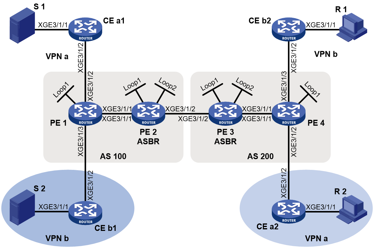
Table 5 Interface and IP address assignment
|
Device |
Interface |
IP address |
Device |
Interface |
IP address |
|
S 1 |
— |
10.11.5.2/24 |
R 1 |
— |
10.11.8.2/24 |
|
S 2 |
— |
10.11.6.2/24 |
R 2 |
— |
10.11.7.2/24 |
|
PE 1 |
XGE3/1/1 |
10.10.1.1/24 |
PE 3 |
XGE3/1/1 |
10.10.2.1/24 |
|
PE 1 |
XGE3/1/2 |
10.11.1.1/24 |
PE 3 |
XGE3/1/2 |
192.168.1.2/24 |
|
PE 1 |
XGE3/1/3 |
10.11.2.1/24 |
PE 3 |
Loop1 |
1.1.1.3/32 |
|
PE 1 |
Loop1 |
1.1.1.1/32 |
PE 3 |
Loop2 |
22.22.22.22/32 |
|
PE 2 |
XGE3/1/1 |
10.10.1.2/24 |
PE 4 |
XGE3/1/1 |
10.10.2.2/24 |
|
PE 2 |
XGE3/1/2 |
192.168.1.1/24 |
PE 4 |
XGE3/1/2 |
10.11.3.1/24 |
|
PE 2 |
Loop1 |
1.1.1.2/32 |
PE 4 |
XGE3/1/3 |
10.11.4.1/32 |
|
PE 2 |
Loop2 |
11.11.11.11/32 |
PE 4 |
Loop1 |
1.1.1.4/32 |
|
CE a1 |
XGE3/1/1 |
10.11.5.1/24 |
CE b1 |
XGE3/1/1 |
10.11.6.1/24 |
|
CE a1 |
XGE3/1/2 |
10.11.1.2/24 |
CE b1 |
XGE3/1/2 |
10.11.2.2/24 |
|
CE a1 |
Loop0 |
2.2.2.2/32 |
CE b2 |
XGE3/1/1 |
10.11.8.1/24 |
|
CE a2 |
XGE3/1/1 |
10.11.7.1/24 |
CE b2 |
XGE3/1/2 |
10.11.4.2/24 |
|
CE a2 |
XGE3/1/2 |
10.11.3.2/24 |
CE b2 |
Loop0 |
3.3.3.3/32 |
Procedure
1. Configure PE 1:
# Configure a global router ID, and enable IP multicast routing on the public network.
<PE1> system-view
[PE1] router id 1.1.1.1
[PE1] multicast routing
[PE1-mrib] quit
# Configure an LSR ID, and enable LDP globally.
[PE1] mpls lsr-id 1.1.1.1
[PE1] mpls ldp
[PE1-ldp] quit
# Create a VPN instance named a, and configure an RD and route targets for the VPN instance.
[PE1] ip vpn-instance a
[PE1-vpn-instance-a] route-distinguisher 100:1
[PE1-vpn-instance-a] vpn-target 100:1 export-extcommunity
[PE1-vpn-instance-a] vpn-target 100:1 import-extcommunity
[PE1-vpn-instance-a] quit
# Enable IP multicast routing for VPN instance a.
[PE1] multicast routing vpn-instance a
[PE1-mrib-a] quit
# Create an MDT-based MVPN for VPN instance a.
[PE1] multicast-vpn vpn-instance a mode mdt
# Create an MVPN IPv4 address family for VPN instance a.
[PE1-mvpn-vpn-instance-a] address-family ipv4
# Specify the default group, the MVPN source interface, and the data group range for VPN instance a.
[PE1-mvpn-vpn-instance-a-ipv4] default-group 239.1.1.1
[PE1-mvpn-vpn-instance-a-ipv4] source loopback 1
[PE1-mvpn-vpn-instance-a-ipv4] data-group 225.1.1.0 28
[PE1-mvpn-vpn-instance-a-ipv4] quit
[PE1-mvpn-vpn-instance-a] quit
# Create a VPN instance named b, and configure an RD and route targets for the VPN instance.
[PE1] ip vpn-instance b
[PE1-vpn-instance-b] route-distinguisher 200:1
[PE1-vpn-instance-b] vpn-target 200:1 export-extcommunity
[PE1-vpn-instance-b] vpn-target 200:1 import-extcommunity
[PE1-vpn-instance-b] quit
# Enable IP multicast routing for VPN instance b.
[PE1] multicast routing vpn-instance b
[PE1-mrib-b] quit
# Create an MDT-based MVPN for VPN instance b.
[PE1] multicast-vpn vpn-instance b mode mdt
# Create an MVPN IPv4 address family for VPN instance b.
[PE1-mvpn-vpn-instance-b] address-family ipv4
# Specify the default group, the MVPN source interface, and the data group range for VPN instance b.
[PE1-mvpn-vpn-instance-b-ipv4] default-group 239.4.4.4
[PE1-mvpn-vpn-instance-b-ipv4] source loopback 1
[PE1-mvpn-vpn-instance-b-ipv4] data-group 225.4.4.0 28
[PE1-mvpn-vpn-instance-b-ipv4] quit
[PE1-mvpn-vpn-instance-b] quit
# Assign an IP address to Ten-GigabitEthernet 3/1/1.
[PE1] interface ten-gigabitethernet 3/1/1
[PE1-Ten-GigabitEthernet3/1/1] ip address 10.10.1.1 24
# Enable PIM-SM, MPLS, and IPv4 LDP on Ten-GigabitEthernet 3/1/1.
[PE1-Ten-GigabitEthernet3/1/1] pim sm
[PE1-Ten-GigabitEthernet3/1/1] mpls enable
[PE1-Ten-GigabitEthernet3/1/1] mpls ldp enable
[PE1-Ten-GigabitEthernet3/1/1] quit
# Associate Ten-GigabitEthernet 3/1/2 with VPN instance a.
[PE1] interface ten-gigabitethernet 3/1/2
[PE1-Ten-GigabitEthernet3/1/2] ip binding vpn-instance a
# Assign an IP address to Ten-GigabitEthernet 3/1/2, and enable PIM-SM on the interface.
[PE1-Ten-GigabitEthernet3/1/2] ip address 10.11.1.1 24
[PE1-Ten-GigabitEthernet3/1/2] pim sm
[PE1-Ten-GigabitEthernet3/1/2] quit
# Associate Ten-GigabitEthernet 3/1/3 with VPN instance b.
[PE1] interface ten-gigabitethernet 3/1/3
[PE1-Ten-GigabitEthernet3/1/3] ip binding vpn-instance b
# Assign an IP address to Ten-GigabitEthernet 3/1/3, and enable PIM-SM on the interface.
[PE1-Ten-GigabitEthernet3/1/3] ip address 10.11.2.1 24
[PE1-Ten-GigabitEthernet3/1/3] pim sm
[PE1-Ten-GigabitEthernet3/1/3] quit
# Assign an IP address to Loopback 1, and enable PIM-SM on the interface.
[PE1] interface loopback 1
[PE1-LoopBack1] ip address 1.1.1.1 32
[PE1-LoopBack1] pim sm
[PE1-LoopBack1] quit
# Configure BGP.
[PE1] bgp 100
[PE1-bgp-default] group pe1-pe2 internal
[PE1-bgp-default] peer pe1-pe2 connect-interface loopback 1
[PE1-bgp-default] peer 1.1.1.2 group pe1-pe2
[PE1-bgp-default] group pe1-pe4 external
[PE1-bgp-default] peer pe1-pe4 as-number 200
[PE1-bgp-default] peer pe1-pe4 ebgp-max-hop 255
[PE1-bgp-default] peer pe1-pe4 connect-interface loopback 1
[PE1-bgp-default] peer 1.1.1.4 group pe1-pe4
[PE1–bgp-default] ip vpn-instance a
[PE1-bgp-default-a] address-family ipv4
[PE1-bgp-default-ipv4-a] import-route ospf 2
[PE1-bgp-default-ipv4-a] import-route direct
[PE1-bgp-default-ipv4-a] quit
[PE1-bgp-default-a] quit
[PE1–bgp-default] ip vpn-instance b
[PE1-bgp-default-b] address-family ipv4
[PE1-bgp-default-ipv4-b] import-route ospf 3
[PE1-bgp-default-ipv4-b] import-route direct
[PE1-bgp-default-ipv4-b] quit
[PE1-bgp-default-b] quit
[PE1–bgp-default] address-family ipv4
[PE1-bgp-default-ipv4] peer pe1-pe2 enable
[PE1-bgp-default-ipv4] peer pe1-pe2 label-route-capability
[PE1-bgp-default-ipv4] quit
[PE1–bgp-default] address-family vpnv4
[PE1–bgp-default-vpnv4] peer pe1-pe4 enable
[PE1–bgp-default-vpnv4] quit
[PE1–bgp-default] quit
# Configure OSPF.
[PE1] ospf 1
[PE1-ospf-1] area 0.0.0.0
[PE1-ospf-1-area-0.0.0.0] network 1.1.1.1 0.0.0.0
[PE1-ospf-1-area-0.0.0.0] network 10.10.1.0 0.0.0.255
[PE1-ospf-1-area-0.0.0.0] quit
[PE1-ospf-1] quit
[PE1] ospf 2 vpn-instance a
[PE1-ospf-2] import-route bgp
[PE1-ospf-2] area 0.0.0.0
[PE1-ospf-2-area-0.0.0.0] network 10.11.1.0 0.0.0.255
[PE1-ospf-2-area-0.0.0.0] quit
[PE1-ospf-2] quit
[PE1] ospf 3 vpn-instance b
[PE1-ospf-3] import-route bgp
[PE1-ospf-3] area 0.0.0.0
[PE1-ospf-3-area-0.0.0.0] network 10.11.2.0 0.0.0.255
[PE1-ospf-3-area-0.0.0.0] quit
[PE1-ospf-3] quit
2. Configure PE 2:
# Configure a global router ID, and enable IP multicast routing on the public network.
<PE2> system-view
[PE2] router id 1.1.1.2
[PE2] multicast routing
[PE2-mrib] quit
# Configure an LSR ID, and enable LDP globally.
[PE2] mpls lsr-id 1.1.1.2
[PE2] mpls ldp
[PE2-mpls-ldp] quit
# Assign an IP address to Ten-GigabitEthernet 3/1/1.
[PE2] interface ten-gigabitethernet 3/1/1
[PE2-Ten-GigabitEthernet3/1/1] ip address 10.10.1.2 24
# Enable PIM-SM, MPLS, and IPv4 LDP on Ten-GigabitEthernet 3/1/1.
[PE2-Ten-GigabitEthernet3/1/1] pim sm
[PE2-Ten-GigabitEthernet3/1/1] mpls enable
[PE2-Ten-GigabitEthernet3/1/1] mpls ldp enable
[PE2-Ten-GigabitEthernet3/1/1] quit
# Assign an IP address to Ten-GigabitEthernet 3/1/2.
[PE2] interface ten-gigabitethernet 3/1/2
[PE2-Ten-GigabitEthernet3/1/2] ip address 192.168.1.1 24
# Enable PIM-SM and MPLS on Ten-GigabitEthernet 3/1/2.
[PE2-Ten-GigabitEthernet3/1/2] pim sm
[PE2-Ten-GigabitEthernet3/1/2] mpls enable
[PE2-Ten-GigabitEthernet3/1/2] quit
# Assign an IP address to Loopback 1, and enable PIM-SM on the interface.
[PE2] interface loopback 1
[PE2-LoopBack1] ip address 1.1.1.2 32
[PE2-LoopBack1] pim sm
[PE2-LoopBack1] quit
# Assign an IP address to Loopback 2, and enable PIM-SM on the interface.
[PE2] interface loopback 2
[PE2-LoopBack2] ip address 11.11.11.11 32
[PE2-LoopBack2] pim sm
[PE2-LoopBack2] quit
# Configure Loopback 2 as a C-BSR and a C-RP.
[PE2] pim
[PE2-pim] c-bsr 11.11.11.11
[PE2-pim] c-rp 11.11.11.11
[PE2-pim] quit
# Configure Ten-GigabitEthernet 3/1/2 as a PIM-SM domain border.
[PE2] interface ten-gigabitethernet 3/1/2
[PE2-Ten-GigabitEthernet3/1/2] pim bsr-boundary
[PE2-Ten-GigabitEthernet3/1/2] quit
# Establish an MSDP peering relationship.
[PE2] msdp
[PE2-msdp] encap-data-enable
[PE2-msdp] peer 1.1.1.3 connect-interface loopback 1
# Configure a static route.
[PE2] ip route-static 1.1.1.3 32 ten-gigabitethernet 3/1/2 192.168.1.2
# Configure a routing policy.
[PE2] route-policy map1 permit node 1
[PE2-route-policy-map1-1] apply mpls-label
[PE2-route-policy-map1-1] quit
[PE2] route-policy map2 permit node 1
[PE2-route-policy-map2-1] apply mpls-label
[PE2-route-policy-map2-1] if-match mpls-label
[PE2-route-policy-map2-1] quit
# Configure BGP.
[PE2] bgp 100
[PE2-bgp-default] group pe2-pe1 internal
[PE2-bgp-default] peer pe2-pe1 connect-interface loopback 1
[PE2-bgp-default] peer 1.1.1.1 group pe2-pe1
[PE2-bgp-default] group pe2-pe3 external
[PE2-bgp-default] peer pe2-pe3 as-number 200
[PE2-bgp-default] peer 192.168.1.2 group pe2-pe3
[PE2-bgp-default] address-family ipv4
[PE2-bgp-default-ipv4] peer pe2-pe1 enable
[PE2-bgp-default-ipv4] peer pe2-pe1 route-policy map2 export
[PE2-bgp-default-ipv4] peer pe2-pe1 label-route-capability
[PE2-bgp-default-ipv4] peer pe2-pe3 enable
[PE2-bgp-default-ipv4] peer pe2-pe3 route-policy map1 export
[PE2-bgp-default-ipv4] peer pe2-pe3 label-route-capability
[PE2-bgp-default-ipv4] import-route ospf 1
[PE2-bgp-default-ipv4] quit
[PE2–bgp-default] quit
# Configure OSPF.
[PE2] ospf 1
[PE2-ospf-1] area 0.0.0.0
[PE2-ospf-1-area-0.0.0.0] network 1.1.1.2 0.0.0.0
[PE2-ospf-1-area-0.0.0.0] network 11.11.11.11 0.0.0.0
[PE2-ospf-1-area-0.0.0.0] network 10.10.1.0 0.0.0.255
[PE2-ospf-1-area-0.0.0.0] quit
[PE2-ospf-1] quit
3. Configure PE 3:
# Configure a global router ID, and enable IP multicast routing on the public network.
<PE3> system-view
[PE3] router id 1.1.1.3
[PE3] multicast routing
[PE3-mrib] quit
# Configure an LSR ID, and enable LDP globally.
[PE3] mpls lsr-id 1.1.1.3
[PE3] mpls ldp
[PE3-ldp] quit
# Assign an IP address to Ten-GigabitEthernet 3/1/1.
[PE3] interface ten-gigabitethernet 3/1/1
[PE3-Ten-GigabitEthernet3/1/1] ip address 10.10.2.1 24
# Enable PIM-SM, MPLS, and IPv4 LDP on Ten-GigabitEthernet 3/1/1.
[PE3-Ten-GigabitEthernet3/1/1] pim sm
[PE3-Ten-GigabitEthernet3/1/1] mpls enable
[PE3-Ten-GigabitEthernet3/1/1] mpls ldp enable
[PE3-Ten-GigabitEthernet3/1/1] quit
# Assign an IP address to Ten-GigabitEthernet 3/1/2.
[PE3] interface ten-gigabitethernet 3/1/2
[PE3-Ten-GigabitEthernet3/1/2] ip address 192.168.1.2 24
# Enable PIM-SM and MPLS on Ten-GigabitEthernet 3/1/2.
[PE3-Ten-GigabitEthernet3/1/2] pim sm
[PE3-Ten-GigabitEthernet3/1/2] mpls enable
[PE3-Ten-GigabitEthernet3/1/2] quit
# Assign an IP address to Loopback 1, and enable PIM-SM on the interface.
[PE3] interface loopback 1
[PE3-LoopBack1] ip address 1.1.1.3 32
[PE3-LoopBack1] pim sm
[PE3-LoopBack1] quit
# Assign an IP address to Loopback 2, and enable PIM-SM on the interface.
[PE3] interface loopback 2
[PE3-LoopBack2] ip address 22.22.22.22 32
[PE3-LoopBack2] pim sm
[PE3-LoopBack2] quit
# Configure Loopback 2 as a C-BSR and a C-RP.
[PE3] pim
[PE3-pim] c-bsr 22.22.22.22
[PE3-pim] c-rp 22.22.22.22
[PE3-pim] quit
# Configure Ten-GigabitEthernet 3/1/2 as a PIM-SM domain border.
[PE3] interface ten-gigabitethernet 3/1/2
[PE3-Ten-GigabitEthernet3/1/2] pim bsr-boundary
[PE3-Ten-GigabitEthernet3/1/2] quit
# Establish an MSDP peering relationship.
[PE3] msdp
[PE3-msdp] encap-data-enable
[PE3-msdp] peer 1.1.1.2 connect-interface loopback 1
# Configure a static route.
[PE3] ip route-static 1.1.1.2 32 ten-gigabitethernet 3/1/2 192.168.1.1
# Configure a routing policy.
[PE3] route-policy map1 permit node 1
[PE3-route-policy-map1-1] apply mpls-label
[PE3-route-policy-map1-1] quit
[PE3] route-policy map2 permit node 1
[PE3-route-policy-map2-1] apply mpls-label
[PE3-route-policy-map2-1] if-match mpls-label
[PE3-route-policy-map2-1] quit
# Configure BGP.
[PE3] bgp 200
[PE3-bgp-default] group pe3-pe4 internal
[PE3-bgp-default] peer pe3-pe4 connect-interface loopback 1
[PE3-bgp-default] peer 1.1.1.4 group pe3-pe4
[PE3-bgp-default] group pe3-pe2 external
[PE3-bgp-default] peer pe3-pe2 as-number 100
[PE3-bgp-default] peer 192.168.1.1 group pe3-pe2
[PE3-bgp-default] address-family ipv4
[PE3-bgp-default-ipv4] peer pe3-pe4 enable
[PE3-bgp-default-ipv4] peer pe3-pe4 route-policy map2 export
[PE3-bgp-default-ipv4] peer pe3-pe4 label-route-capability
[PE3-bgp-default-ipv4] peer pe3-pe2 enable
[PE3-bgp-default-ipv4] peer pe3-pe2 route-policy map1 export
[PE3-bgp-default-ipv4] peer pe3-pe2 label-route-capability
[PE3-bgp-default-ipv4] import-route ospf 1
[PE3-bgp-default-ipv4] quit
[PE3–bgp-default] quit
# Configure OSPF.
[PE3] ospf 1
[PE3-ospf-1] area 0.0.0.0
[PE3-ospf-1-area-0.0.0.0] network 1.1.1.3 0.0.0.0
[PE3-ospf-1-area-0.0.0.0] network 22.22.22.22 0.0.0.0
[PE3-ospf-1-area-0.0.0.0] network 10.10.2.0 0.0.0.255
[PE3-ospf-1-area-0.0.0.0] quit
[PE3-ospf-1] quit
4. Configure PE 4:
# Configure a global router ID, and enable IP multicast routing on the public network.
<PE4> system-view
[PE4] router id 1.1.1.4
[PE4] multicast routing
[PE4-mrib] quit
# Configure an LSR ID, and enable LDP globally.
[PE4] mpls lsr-id 1.1.1.4
[PE4] mpls ldp
[PE4-ldp] quit
# Create a VPN instance named a, and configure an RD and route targets for the VPN instance.
[PE4] ip vpn-instance a
[PE4-vpn-instance-a] route-distinguisher 100:1
[PE4-vpn-instance-a] vpn-target 100:1 export-extcommunity
[PE4-vpn-instance-a] vpn-target 100:1 import-extcommunity
[PE4-vpn-instance-a] quit
# Enable IP multicast routing for VPN instance a.
[PE4] multicast routing vpn-instance a
[PE4-mrib-a] quit
# Create an MDT-based MVPN for VPN instance a.
[PE4] multicast-vpn vpn-instance a mode mdt
# Create an MVPN IPv4 address family for VPN instance a.
[PE4-mvpn-vpn-instance-a] address-family ipv4
# Specify the default group, the MVPN source interface, and the data group range for VPN instance a.
[PE4-mvpn-vpn-instance-a-ipv4] default-group 239.1.1.1
[PE4-mvpn-vpn-instance-a-ipv4] source loopback 1
[PE4-mvpn-vpn-instance-a-ipv4] data-group 225.1.1.0 28
[PE4-mvpn-vpn-instance-a-ipv4] quit
[PE4-mvpn-vpn-instance-a] quit
# Create a VPN instance named b, and configure an RD and route targets for the VPN instance.
[PE4] ip vpn-instance b
[PE4-vpn-instance-b] route-distinguisher 200:1
[PE4-vpn-instance-b] vpn-target 200:1 export-extcommunity
[PE4-vpn-instance-b] vpn-target 200:1 import-extcommunity
[PE4-vpn-instance-b] quit
# Enable IP multicast routing for VPN instance b.
[PE4] multicast routing vpn-instance b
[PE4-mrib-b] quit
# Create an MDT-based MVPN for VPN instance b.
[PE4] multicast-vpn vpn-instance b mode mdt
# Create an MVPN IPv4 address family for VPN instance b.
[PE4-mvpn-vpn-instance-b] address-family ipv4
# Specify the default group, MVPN source interface, and the data group range for VPN instance b.
[PE4-mvpn-vpn-instance-b-ipv4] default-group 239.4.4.4
[PE4-mvpn-vpn-instance-b-ipv4] source loopback 1
[PE4-mvpn-vpn-instance-b-ipv4] data-group 225.4.4.0 28
[PE4-mvpn-vpn-instance-b-ipv4] quit
[PE4-mvpn-vpn-instance-b] quit
# Assign an IP address to Ten-GigabitEthernet 3/1/1.
[PE4] interface ten-gigabitethernet 3/1/1
[PE4-Ten-GigabitEthernet3/1/1] ip address 10.10.2.2 24
# Enable PIM-SM, MPLS, and IPv4 LDP on Ten-GigabitEthernet 3/1/1.
[PE4-Ten-GigabitEthernet3/1/1] pim sm
[PE4-Ten-GigabitEthernet3/1/1] mpls enable
[PE4-Ten-GigabitEthernet3/1/1] mpls ldp enable
[PE4-Ten-GigabitEthernet3/1/1] quit
# Associate Ten-GigabitEthernet 3/1/2 with VPN instance a.
[PE4] interface ten-gigabitethernet 3/1/2
[PE4-Ten-GigabitEthernet3/1/2] ip binding vpn-instance a
# Assign an IP address to Ten-GigabitEthernet 3/1/2, and enable PIM-SM on the interface.
[PE4-Ten-GigabitEthernet3/1/2] ip address 10.11.3.1 24
[PE4-Ten-GigabitEthernet3/1/2] pim sm
[PE4-Ten-GigabitEthernet3/1/2] quit
# Associate Ten-GigabitEthernet 3/1/3 with VPN instance b.
[PE4] interface ten-gigabitethernet 3/1/3
[PE4-Ten-GigabitEthernet3/1/3] ip binding vpn-instance b
# Assign an IP address to Ten-GigabitEthernet 3/1/3, and enable PIM-SM on the interface.
[PE4-Ten-GigabitEthernet3/1/3] ip address 10.11.4.1 24
[PE4-Ten-GigabitEthernet3/1/3] pim sm
[PE4-Ten-GigabitEthernet3/1/3] quit
# Assign an IP address to Loopback 1, and enable PIM-SM on the interface.
[PE4] interface loopback 1
[PE4-LoopBack1] ip address 1.1.1.4 32
[PE4-LoopBack1] pim sm
[PE4-LoopBack1] quit
# Configure BGP.
[PE4] bgp 200
[PE4-bgp-default] group pe4-pe3 internal
[PE4-bgp-default] peer pe4-pe3 connect-interface loopback 1
[PE4-bgp-default] peer 1.1.1.3 group pe4-pe3
[PE4-bgp-default] group pe4-pe1 external
[PE4-bgp-default] peer pe4-pe1 as-number 100
[PE4-bgp-default] peer pe4-pe1 ebgp-max-hop 255
[PE4-bgp-default] peer pe4-pe1 connect-interface loopback 1
[PE4-bgp-default] peer 1.1.1.1 group pe4-pe1
[PE4–bgp-default] ip vpn-instance a
[PE4-bgp-default-a] address-family ipv4
[PE4-bgp-default-ipv4-a] import-route ospf 2
[PE4-bgp-default-ipv4-a] import-route direct
[PE4-bgp-default-ipv4-a] quit
[PE4-bgp-default-a] quit
[PE4–bgp-default] ip vpn-instance b
[PE4-bgp-default-b] address-family ipv4
[PE4-bgp-default-ipv4-b] import-route ospf 3
[PE4-bgp-default-ipv4-b] import-route direct
[PE4-bgp-default-ipv4-b] quit
[PE4-bgp-default-b] quit
[PE4–bgp-default] address-family ipv4
[PE4-bgp-default-ipv4] peer pe4-pe3 enable
[PE4-bgp-default-ipv4] peer pe4-pe3 label-route-capability
[PE4-bgp-default-ipv4] quit
[PE4–bgp-default] address-family vpnv4
[PE4–bgp-default-vpnv4] peer pe4-pe1 enable
[PE4–bgp-default-vpnv4] quit
[PE4–bgp-default] quit
# Configure OSPF.
[PE4] ospf 1
[PE4-ospf-1] area 0.0.0.0
[PE4-ospf-1-area-0.0.0.0] network 1.1.1.4 0.0.0.0
[PE4-ospf-1-area-0.0.0.0] network 10.10.2.0 0.0.0.255
[PE4-ospf-1-area-0.0.0.0] quit
[PE4-ospf-1] quit
[PE4] ospf 2 vpn-instance a
[PE4-ospf-2] import-route bgp
[PE4-ospf-2] area 0.0.0.0
[PE4-ospf-2-area-0.0.0.0] network 10.11.3.0 0.0.0.255
[PE4-ospf-2-area-0.0.0.0] quit
[PE4-ospf-2] quit
[PE4] ospf 3 vpn-instance b
[PE4-ospf-3] import-route bgp
[PE4-ospf-3] area 0.0.0.0
[PE4-ospf-3-area-0.0.0.0] network 10.11.4.0 0.0.0.255
[PE4-ospf-3-area-0.0.0.0] quit
[PE4-ospf-3] quit
5. Configure CE a1:
# Enable IP multicast routing.
<CEa1> system-view
[CEa1] multicast routing
[CEa1-mrib] quit
# Assign an IP address to Ten-GigabitEthernet 3/1/1, and enable PIM-SM on the interface.
[CEa1] interface ten-gigabitethernet 3/1/1
[CEa1-Ten-GigabitEthernet3/1/1] ip address 10.11.5.1 24
[CEa1-Ten-GigabitEthernet3/1/1] pim sm
[CEa1-Ten-GigabitEthernet3/1/1] quit
# Assign an IP address to Ten-GigabitEthernet 3/1/2, and enable PIM-SM on the interface.
[CEa1] interface ten-gigabitethernet 3/1/2
[CEa1-Ten-GigabitEthernet3/1/2] ip address 10.11.1.2 24
[CEa1-Ten-GigabitEthernet3/1/2] pim sm
[CEa1-Ten-GigabitEthernet3/1/2] quit
# Assign an IP address to Loopback 1, and enable PIM-SM on the interface.
[CEa1] interface loopback 1
[CEa1-LoopBack1] ip address 2.2.2.2 32
[CEa1-LoopBack1] pim sm
[CEa1-LoopBack1] quit
# Configure Loopback 1 as a C-BSR and a C-RP.
[CEa1] pim
[CEa1-pim] c-bsr 2.2.2.2
[CEa1-pim] c-rp 2.2.2.2 1
[CEa1-pim] quit
# Configure OSPF.
[CEa1] ospf 1
[CEa1-ospf-1] area 0.0.0.0
[CEa1-ospf-1-area-0.0.0.0] network 2.2.2.2 0.0.0.0
[CEa1-ospf-1-area-0.0.0.0] network 10.11.1.0 0.0.0.255
[CEa1-ospf-1-area-0.0.0.0] network 10.11.5.0 0.0.0.255
[CEa1-ospf-1-area-0.0.0.0] quit
[CEa1-ospf-1] quit
6. Configure CE b1:
# Enable IP multicast routing.
<CEb1> system-view
[CEb1] multicast routing
[CEb1-mrib] quit
# Assign an IP address to Ten-GigabitEthernet 3/1/1, and enable PIM-SM on the interface.
[CEb1] interface ten-gigabitethernet 3/1/1
[CEb1-Ten-GigabitEthernet3/1/1] ip address 10.11.6.1 24
[CEb1-Ten-GigabitEthernet3/1/1] pim sm
[CEb1-Ten-GigabitEthernet3/1/1] quit
# Assign an IP address to Ten-GigabitEthernet 3/1/2, and enable PIM-SM on the interface.
[CEb1] interface ten-gigabitethernet 3/1/2
[CEb1-Ten-GigabitEthernet3/1/2] ip address 10.11.2.2 24
[CEb1-Ten-GigabitEthernet3/1/2] pim sm
[CEb1-Ten-GigabitEthernet3/1/2] quit
# Configure OSPF.
[CEb1] ospf 1
[CEb1-ospf-1] area 0.0.0.0
[CEb1-ospf-1-area-0.0.0.0] network 10.11.2.0 0.0.0.255
[CEb1-ospf-1-area-0.0.0.0] network 10.11.6.0 0.0.0.255
[CEb1-ospf-1-area-0.0.0.0] quit
[CEb1-ospf-1] quit
7. Configure CE a2:
# Enable IP multicast routing.
<CEa2> system-view
[CEa2] multicast routing
[CEa2-mrib] quit
# Assign an IP address to Ten-GigabitEthernet 3/1/1, and enable IGMP on the interface.
[CEa2] interface ten-gigabitethernet 3/1/1
[CEa2-Ten-GigabitEthernet3/1/1] ip address 10.11.7.1 24
[CEa2-Ten-GigabitEthernet3/1/1] igmp enable
[CEa2-Ten-GigabitEthernet3/1/1] quit
# Assign an IP address to Ten-GigabitEthernet 3/1/2, and enable PIM-SM on the interface.
[CEa2] interface ten-gigabitethernet 3/1/2
[CEa2-Ten-GigabitEthernet3/1/2] ip address 10.11.3.2 24
[CEa2-Ten-GigabitEthernet3/1/2] pim sm
[CEa2-Ten-GigabitEthernet3/1/2] quit
# Configure OSPF.
[CEa2] ospf 1
[CEa2-ospf-1] area 0.0.0.0
[CEa2-ospf-1-area-0.0.0.0] network 10.11.3.0 0.0.0.255
[CEa2-ospf-1-area-0.0.0.0] network 10.11.7.0 0.0.0.255
[CEa2-ospf-1-area-0.0.0.0] quit
[CEa2-ospf-1] quit
8. Configure CE b2:
# Enable IP multicast routing.
<CEb2> system-view
[CEb2] multicast routing
[CEb2-mrib] quit
# Assign an IP address to Ten-GigabitEthernet 3/1/1, and enable IGMP on the interface.
[CEb2] interface ten-gigabitethernet 3/1/1
[CEb2-Ten-GigabitEthernet3/1/1] ip address 10.11.8.1 24
[CEb2-Ten-GigabitEthernet3/1/1] igmp enable
[CEb2-Ten-GigabitEthernet3/1/1] quit
# Assign an IP address to Ten-GigabitEthernet 3/1/2, and enable PIM-SM on the interface.
[CEb2] interface ten-gigabitethernet 3/1/2
[CEb2-Ten-GigabitEthernet3/1/2] ip address 10.11.4.2 24
[CEb2-Ten-GigabitEthernet3/1/2] pim sm
[CEb2-Ten-GigabitEthernet3/1/2] quit
# Assign an IP address to Loopback 1, and enable PIM-SM on the interface.
[CEb2] interface loopback 1
[CEb2-LoopBack1] ip address 3.3.3.3 32
[CEb2-LoopBack1] pim sm
[CEb2-LoopBack1] quit
# Configure Loopback 1 as a C-BSR and a C-RP.
[CEb2] pim
[CEb2-pim] c-bsr 3.3.3.3
[CEb2-pim] c-rp 3.3.3.3
[CEb2-pim] quit
# Configure OSPF.
[CEb2] ospf 1
[CEb2-ospf-1] area 0.0.0.0
[CEb2-ospf-1-area-0.0.0.0] network 3.3.3.3 0.0.0.0
[CEb2-ospf-1-area-0.0.0.0] network 10.11.4.0 0.0.0.255
[CEb2-ospf-1-area-0.0.0.0] network 10.11.8.0 0.0.0.255
[CEb2-ospf-1-area-0.0.0.0] quit
[CEb2-ospf-1] quit
Verifying the configuration
# Display information about the local default group for IPv4 multicast transmission in each VPN instance on PE 1.
[PE1] display multicast-vpn default-group local
MVPN local default-group information:
Group address Source address Interface VPN instance
239.1.1.1 1.1.1.1 MTunnel0 a
239.4.4.4 1.1.1.1 MTunnel1 b
# Display information about the local default group for IPv4 multicast transmission in each VPN instance on PE 4.
[PE4] display multicast-vpn default-group local
MVPN local default-group information:
Group address Source address Interface VPN instance
239.1.1.1 1.1.1.4 MTunnel0 a
239.4.4.4 1.1.1.4 MTunnel1 b
Example: Configuring inter-AS option A mLDP-based MVPN
Network configuration
As shown in Figure 29, configure inter-AS option A mLDP-based MVPN to meet the following requirements:
|
Item |
Network configuration |
|
Multicast sources and receivers |
· In VPN instance a, S 1 is a multicast source, and R 2 is a receiver. · In VPN instance b, S 2 is a multicast source, and R 1 is a receiver. |
|
VPN instances to which PE interfaces belong |
· PE 1: Ten-GigabitEthernet 3/1/2 belongs to VPN instance a. Ten-GigabitEthernet 3/1/3 belongs to VPN instance b. Ten-GigabitEthernet 3/1/1 and Loopback 1 belong to the public network. · PE 2: Ten-GigabitEthernet 3/1/1, and Loopback 1 belong to the public network. Ten-GigabitEthernet 3/1/2 belongs to VPN instance a. Ten-GigabitEthernet 3/1/3 belongs to VPN instance b. · PE 3: Ten-GigabitEthernet 3/1/1 and Loopback 1 belong to the public network. Ten-GigabitEthernet 3/1/2 belongs to VPN instance a. Ten-GigabitEthernet 3/1/3 belongs to VPN instance b. · PE 4: Ten-GigabitEthernet 3/1/2 belongs to VPN instance a. Ten-GigabitEthernet 3/1/3 belongs to VPN instance b. Ten-GigabitEthernet 3/1/1 and Loopback 1 belong to the public network. |
|
Unicast routing protocols and MPLS |
· Configure OSPF in AS 100 and AS 200, and configure OSPF between the PEs and CEs. · Establish IBGP peer connections between PE 1, PE 2, PE 3, and PE 4 on their respective Loopback 1. · Establish EBGP peer connections between Ten-GigabitEthernet 3/1/2 on PE 2 and PE 3. · Configure BGP IPv4 MVPN peer connections between PE 1, PE 2, PE 3, and PE 4 on their respective Loopback 1. · Configure MPLS in AS 100 and AS 200. · Enable MPLS on P 1 and P 2. |
|
IP multicast routing |
· Enable IP multicast routing for VPN instance a on PE 1 and PE 4. · Enable IP multicast routing for VPN instance b on PE 1 and PE 4. · Enable IP multicast routing on CE a1, CE a2, CE b1, and CE b2. |
|
IGMP |
· Enable IGMPv2 on Ten-GigabitEthernet 3/1/1 of CE a2. · Enable IGMPv3 on Ten-GigabitEthernet 3/1/1 of CE b2. |
|
PIM |
Enable PIM-SM for VPN instances a and b: · Enable PIM-SM on all private network interfaces of PE 1 and PE 4. · Enable PIM-SM on all interfaces that do not have attached receiver hosts on CE a1, CE a2, CE b1, and CE b2. · Configure Ten-GigabitEthernet 3/1/2 of CE a1 as a C-BSR and a C-RP for VPN instance a in AS 100 to provide services for all multicast groups. · Configure Ten-GigabitEthernet 3/1/2 of CE b1 as a C-BSR and a C-RP for VPN instance b in AS 200 to provide services for all multicast groups. |
|
MSDP |
Enable MSDP on CE a1, and specify Ten-GigabitEthernet 3/1/2 as the local MSDP connection interface. Enable MSDP on CE a2, and specify Ten-GigabitEthernet 3/1/2 as the local MSDP connection interface. |

Table 6 Interface and IP address assignment
|
Device |
Interface |
IP address |
Device |
Interface |
IP address |
|
S 1 |
— |
12.1.1.100/24 |
R 1 |
— |
12.4.1.100/24 |
|
S 2 |
— |
12.2.1.100/24 |
R 2 |
— |
12.3.1.100/24 |
|
PE 1 |
XGE3/1/1 |
10.1.1.1/24 |
PE 3 |
XGE3/1/1 |
10.4.1.1/24 |
|
PE 1 |
XGE3/1/2 |
11.1.1.1/24 |
PE 3 |
XGE3/1/2 |
10.3.1.2/24 |
|
PE 1 |
XGE3/1/3 |
11.2.1.1/24 |
PE 3 |
XGE3/1/3 |
10.6.1.2/24 |
|
PE 1 |
Loop1 |
1.1.1.1/32 |
PE 3 |
Loop1 |
3.3.3.3/32 |
|
PE 2 |
XGE3/1/1 |
10.2.1.2/24 |
PE 4 |
XGE3/1/1 |
10.5.1.2/24 |
|
PE 2 |
XGE3/1/2 |
10.3.1.1/24 |
PE 4 |
XGE3/1/2 |
11.3.1.1/24 |
|
PE 2 |
XGE3/1/3 |
10.6.1.1/24 |
PE 4 |
XGE3/1/3 |
11.4.1.1/24 |
|
PE 2 |
Loop1 |
2.2.2.2/32 |
PE 4 |
Loop1 |
4.4.4.4/24 |
|
P 1 |
XGE3/1/1 |
10.1.1.2/24 |
P 2 |
XGE3/1/1 |
10.5.1.1/24 |
|
P 1 |
XGE3/1/2 |
10.2.1.1/24 |
P 2 |
XGE3/1/2 |
10.4.1.2/24 |
|
P 1 |
Loop1 |
5.5.5.5/32 |
P 2 |
Loop1 |
6.6.6.6/32 |
|
CE a1 |
XGE3/1/1 |
12.1.1.1/24 |
CE b1 |
XGE3/1/1 |
12.2.1.1/24 |
|
CE a1 |
XGE3/1/2 |
11.1.1.2/24 |
CE b1 |
XGE3/1/2 |
11.2.1.2/24 |
|
CE a2 |
XGE3/1/1 |
12.3.1.1/24 |
CE b2 |
XGE3/1/1 |
12.4.1.1/24 |
|
CE a2 |
XGE3/1/2 |
11.3.1.2/24 |
CE b2 |
XGE3/1/2 |
11.4.1.2/24 |
Procedure
1. Configure PE 1:
# Configure a global router ID.
<PE1> system-view
[PE1] router id 1.1.1.1
[PE1] quit
# Configure an LSR ID, and enable LDP and mLDP P2MP globally.
[PE1] mpls lsr-id 1.1.1.1
[PE1] mpls ldp
[PE1-ldp] mldp p2mp
[PE1-ldp] quit
# Create a VPN instance named a, and configure the RD and route targets for the VPN instance.
[PE1] ip vpn-instance a
[PE1-vpn-instance-a] route-distinguisher 100:1
[PE1-vpn-instance-a] vpn-target 100:1 export-extcommunity
[PE1-vpn-instance-a] vpn-target 100:1 import-extcommunity
[PE1-vpn-instance-a] quit
# Enable IP multicast routing for VPN instance a.
[PE1] multicast routing vpn-instance a
[PE1-mrib-a] quit
# Create an mLDP-based MVPN for VPN instance a.
[PE1] multicast-vpn vpn-instance a mode mldp
# Create an MVPN IPv4 address family for VPN instance a.
[PE1-mvpn-vpn-instance-a] address-family ipv4
# Specify the MVPN source interface for VPN instance a.
[PE1-mvpn-vpn-instance-a-ipv4] source loopback 1
# Enable dynamic inclusive tunnel creation, dynamic selective tunnel creation, and inter-AS auto-discovery for VPN instance a.
[PE1-mvpn-vpn-instance-a-ipv4] inclusive-tunnel dynamic
[PE1-mvpn-vpn-instance-a-ipv4] selective-tunnel dynamic
[PE1-mvpn-vpn-instance-a-ipv4] auto-discovery inter-as
[PE1-mvpn-vpn-instance-a-ipv4] quit
[PE1-mvpn-vpn-instance-a] quit
# Create a VPN instance named b, and configure the RD and route targets for the VPN instance.
[PE1] ip vpn-instance b
[PE1-vpn-instance-b] route-distinguisher 200:1
[PE1-vpn-instance-b] vpn-target 200:1 export-extcommunity
[PE1-vpn-instance-b] vpn-target 200:1 import-extcommunity
[PE1-vpn-instance-b] quit
# Enable IP multicast routing for VPN instance b.
[PE1] multicast routing vpn-instance b
[PE1-mrib-b] quit
# Create an mLDP-based MVPN for VPN instance b.
[PE1] multicast-vpn vpn-instance b mode mldp
# Create an MVPN IPv4 address family for VPN instance b.
[PE1-mvpn-vpn-instance-b] address-family ipv4
# Specify the MVPN source interface for VPN instance b.
[PE1-mvpn-vpn-instance-b-ipv4] source loopback 1
# Enable dynamic inclusive tunnel creation, dynamic selective tunnel creation, and inter-AS auto-discovery for VPN instance b.
[PE1-mvpn-vpn-instance-b-ipv4] inclusive-tunnel dynamic
[PE1-mvpn-vpn-instance-b-ipv4] selective-tunnel dynamic
[PE1-mvpn-vpn-instance-b-ipv4] auto-discovery inter-as
[PE1-mvpn-vpn-instance-b-ipv4] quit
[PE1-mvpn-vpn-instance-b] quit
# Assign an IP address to Ten-GigabitEthernet 3/1/1, and enable MPLS and IPv4 LDP on the interface.
[PE1] interface ten-gigabitethernet 3/1/1
[PE1-Ten-GigabitEthernet3/1/1] ip address 10.1.1.1 24
[PE1-Ten-GigabitEthernet3/1/1] mpls enable
[PE1-Ten-GigabitEthernet3/1/1] mpls ldp enable
[PE1-Ten-GigabitEthernet3/1/1] quit
# Associate Ten-GigabitEthernet 3/1/2 with VPN instance a, assign an IP address to the interface, and enable PIM-SM on the interface.
[PE1] interface ten-gigabitethernet 3/1/2
[PE1-Ten-GigabitEthernet3/1/2] ip binding vpn-instance a
[PE1-Ten-GigabitEthernet3/1/2] ip address 11.1.1.1 24
[PE1-Ten-GigabitEthernet3/1/2] pim sm
[PE1-Ten-GigabitEthernet3/1/2] quit
# Associate Ten-GigabitEthernet 3/1/3 with VPN instance b, assign an IP address to the interface, and enable PIM-SM on the interface.
[PE1] interface ten-gigabitethernet 3/1/3
[PE1-Ten-GigabitEthernet3/1/3] ip binding vpn-instance b
[PE1-Ten-GigabitEthernet3/1/3] ip address 11.2.1.1 24
[PE1-Ten-GigabitEthernet3/1/3] pim sm
[PE1-Ten-GigabitEthernet3/1/3] quit
# Assign an IP address to Loopback 1.
[PE1] interface loopback 1
[PE1-LoopBack1] ip address 1.1.1.1 32
[PE1-LoopBack1] quit
# Configure BGP.
[PE1] bgp 100
[PE1-bgp-default] peer 2.2.2.2 as-number 100
[PE1-bgp-default] peer 2.2.2.2 connect-interface loopback 1
[PE1-bgp-default] address-family ipv4 mvpn
[PE1-bgp-default-mvpn] peer 2.2.2.2 enable
[PE1-bgp-default-mvpn] quit
[PE1–bgp-default] address-family vpnv4
[PE1–bgp-default-vpnv4] peer 2.2.2.2 enable
[PE1–bgp-default-vpnv4] peer 2.2.2.2 next-hop-local
[PE1–bgp-default-vpnv4] mvpn-advertise-rt-import
[PE1–bgp-default-vpnv4] quit
[PE1–bgp-default] ip vpn-instance a
[PE1-bgp-default-a] address-family ipv4
[PE1-bgp-default-ipv4-a] import-route ospf 2
[PE1-bgp-default-ipv4-a] import-route direct
[PE1-bgp-default-ipv4-a] quit
[PE1-bgp-default-a] quit
[PE1–bgp-default] ip vpn-instance b
[PE1-bgp-default-b] address-family ipv4
[PE1-bgp-default-ipv4-b] import-route ospf 3
[PE1-bgp-default-ipv4-b] import-route direct
[PE1-bgp-default-ipv4-b] quit
[PE1-bgp-default-b] quit
[PE1–bgp-default] quit
# Configure OSPF.
[PE1] ospf 1
[PE1-ospf-1] area 0.0.0.0
[PE1-ospf-1-area-0.0.0.0] network 1.1.1.1 0.0.0.0
[PE1-ospf-1-area-0.0.0.0] network 10.1.1.0 0.0.0.255
[PE1-ospf-1-area-0.0.0.0] quit
[PE1-ospf-1] quit
[PE1] ospf 2 vpn-instance a
[PE1-ospf-2] area 0.0.0.0
[PE1-ospf-2-area-0.0.0.0] network 11.1.1.0 0.0.0.255
[PE1-ospf-2-area-0.0.0.0] quit
[PE1-ospf-2] quit
[PE1] ospf 3 vpn-instance b
[PE1-ospf-3] area 0.0.0.0
[PE1-ospf-3-area-0.0.0.0] network 11.2.1.0 0.0.0.255
[PE1-ospf-3-area-0.0.0.0] quit
[PE1-ospf-3] quit
2. Configure PE 2:
# Configure a global router ID.
<PE2> system-view
[PE2] router id 2.2.2.2
[PE2] quit
# Configure an LSR ID, and enable LDP and mLDP P2MP globally.
[PE2] mpls lsr-id 2.2.2.2
[PE2] mpls ldp
[PE2-ldp] mldp p2mp
[PE2-ldp] quit
# Create a VPN instance named a, and configure the RD and route targets for the VPN instance.
[PE2] ip vpn-instance a
[PE2-vpn-instance-a] route-distinguisher 100:1
[PE2-vpn-instance-a] vpn-target 100:1 export-extcommunity
[PE2-vpn-instance-a] vpn-target 100:1 import-extcommunity
[PE2-vpn-instance-a] quit
# Enable IP multicast routing for VPN instance a.
[PE2] multicast routing vpn-instance a
[PE2-mrib-a] quit
# Create an mLDP-based MVPN for VPN instance a.
[PE2] multicast-vpn vpn-instance a mode mldp
# Create an MVPN IPv4 address family for VPN instance a.
[PE2-mvpn-vpn-instance-a] address-family ipv4
# Specify the MVPN source interface, enable dynamic inclusive tunnel creation, and enable dynamic selective tunnel creation for VPN instance a.
[PE2-mvpn-vpn-instance-a-ipv4] source loopback 1
[PE2-mvpn-vpn-instance-a-ipv4] inclusive-tunnel dynamic
[PE2-mvpn-vpn-instance-a-ipv4] selective-tunnel dynamic
[PE2-mvpn-vpn-instance-a-ipv4] quit
[PE2-mvpn-vpn-instance-a] quit
# Create a VPN instance named b, and configure the RD and route targets for the VPN instance.
[PE2] ip vpn-instance b
[PE2-vpn-instance-b] route-distinguisher 200:1
[PE2-vpn-instance-b] vpn-target 200:1 export-extcommunity
[PE2-vpn-instance-b] vpn-target 200:1 import-extcommunity
[PE2-vpn-instance-b] quit
# Enable IP multicast routing for VPN instance b.
[PE2] multicast routing vpn-instance b
[PE2-mrib-b] quit
# Create an mLDP-based MVPN for VPN instance b.
[PE2] multicast-vpn vpn-instance b mode mldp
# Create an MVPN IPv4 address family for VPN instance b.
[PE2-mvpn-vpn-instance-b] address-family ipv4
# Specify the MVPN source interface, enable dynamic inclusive tunnel creation, and enable dynamic selective tunnel creation for VPN instance b.
[PE2-mvpn-vpn-instance-b-ipv4] source loopback 1
[PE2-mvpn-vpn-instance-b-ipv4] inclusive-tunnel dynamic
[PE2-mvpn-vpn-instance-b-ipv4] selective-tunnel dynamic
[PE2-mvpn-vpn-instance-b-ipv4] quit
[PE2-mvpn-vpn-instance-b] quit
# Assign an IP address to Ten-GigabitEthernet 3/1/1, and enable MPLS and IPv4 LDP on the interface.
[PE2] interface ten-gigabitethernet 3/1/1
[PE2-Ten-GigabitEthernet3/1/1] ip address 10.2.1.2 24
[PE2-Ten-GigabitEthernet3/1/1] mpls enable
[PE2-Ten-GigabitEthernet3/1/1] mpls ldp enable
[PE2-Ten-GigabitEthernet3/1/1] quit
# Associate Ten-GigabitEthernet 3/1/2 with VPN instance a, and assign an IP address to the interface.
[PE2] interface ten-gigabitethernet 3/1/2
[PE2-Ten-GigabitEthernet3/1/2] ip binding vpn-instance a
[PE2-Ten-GigabitEthernet3/1/2] ip address 10.3.1.1 24
# Enable PIM-SM on Ten-GigabitEthernet 3/1/2, and configure the interface as a PIM-SM domain border.
[PE2-Ten-GigabitEthernet3/1/2] pim sm
[PE2-Ten-GigabitEthernet3/1/2] pim bsr-boundary
[PE2-Ten-GigabitEthernet3/1/2] quit
# Associate Ten-GigabitEthernet 3/1/3 with VPN instance b, assign an IP address to the interface, and enable PIM-SM on the interface.
[PE2] interface ten-gigabitethernet 3/1/3
[PE2-Ten-GigabitEthernet3/1/3] ip binding vpn-instance b
[PE2-Ten-GigabitEthernet3/1/3] ip address 10.6.1.1 24
[PE2-Ten-GigabitEthernet3/1/3] pim sm
[PE2-Ten-GigabitEthernet3/1/3] quit
# Assign an IP address to Loopback 1.
[PE2] interface loopback 1
[PE2-LoopBack1] ip address 2.2.2.2 32
[PE2-LoopBack1] quit
# Configure BGP.
[PE2] bgp 100
[PE2-bgp-default] peer 1.1.1.1 as-number 100
[PE2-bgp-default] peer 1.1.1.1 connect-interface loopback 1
[PE2-bgp-default] address-family ipv4 mvpn
[PE2-bgp-default-mvpn] peer 1.1.1.1 enable
[PE2-bgp-default-mvpn] quit
[PE2-bgp-default] address-family vpnv4
[PE2-bgp-default-vpnv4] mvpn-advertise-rt-import
[PE2-bgp-default-vpnv4] peer 1.1.1.1 enable
[PE2-bgp-default-vpnv4] peer 1.1.1.1 next-hop-local
[PE2-bgp-default-vpnv4] quit
[PE2-bgp-default] ip vpn-instance a
[PE2-bgp-default] peer 10.3.1.2 as-number 200
[PE2-bgp-default-a] address-family ipv4 unicast
[PE2-bgp-default-ipv4-a] import-route direct
[PE2-bgp-default-ipv4-a] peer 10.3.1.2 enable
[PE2-bgp-default-ipv4-a] quit
[PE2-bgp-default-a] quit
[PE2-bgp-default]ip vpn-instance b
[PE2-bgp-default] peer 10.6.1.2 as-number 200
[PE2-bgp-default-b] address-family ipv4 unicast
[PE2-bgp-default-ipv4-b] import-route direct
[PE2-bgp-default-ipv4-b] peer 10.6.1.2 enable
[PE2-bgp-default-ipv4-b] quit
[PE2-bgp-default-b] quit
[PE2–bgp-default] quit
# Configure OSPF.
[PE2] ospf 1
[PE2-ospf-1] area 0.0.0.0
[PE2-ospf-1-area-0.0.0.0] network 2.2.2.2 0.0.0.0
[PE2-ospf-1-area-0.0.0.0] network 10.2.1.0 0.0.0.255
[PE2-ospf-1-area-0.0.0.0] quit
[PE2-ospf-1] quit
3. Configure PE 3:
# Configure a global router ID.
<PE3> system-view
[PE3] router id 3.3.3.3
# Configure an LSR ID, and enable LDP and mLDP P2MP globally.
[PE3] mpls lsr-id 3.3.3.3
[PE3] mpls ldp
[PE3-ldp] mldp p2mp
[PE3-ldp] quit
# Create a VPN instance named a, and configure the RD and route targets for the VPN instance.
[PE3] ip vpn-instance a
[PE3-vpn-instance-a] route-distinguisher 300:1
[PE3-vpn-instance-a] vpn-target 100:1 export-extcommunity
[PE3-vpn-instance-a] vpn-target 100:1 import-extcommunity
[PE3-vpn-instance-a] quit
# Enable IP multicast routing for VPN instance a.
[PE3] multicast routing vpn-instance a
[PE3-mrib-a] quit
# Create an mLDP-based MVPN for VPN instance a.
[PE3] multicast-vpn vpn-instance a mode mldp
# Create an MVPN IPv4 address family for VPN instance a.
[PE3-mvpn-vpn-instance-a] address-family ipv4
# Specify the MVPN source interface for VPN instance a.
[PE3-mvpn-vpn-instance-a-ipv4] source loopback 1
# Enable dynamic inclusive tunnel creation, dynamic selective tunnel creation, and inter-AS auto-discovery for VPN instance a.
[PE3-mvpn-vpn-instance-a-ipv4] inclusive-tunnel dynamic
[PE3-mvpn-vpn-instance-a-ipv4] selective-tunnel dynamic
[PE3-mvpn-vpn-instance-a-ipv4] auto-discovery inter-as
[PE3-mvpn-vpn-instance-a-ipv4] quit
[PE3-mvpn-vpn-instance-a] quit
# Create a VPN instance named b, and configure the RD and route targets for the VPN instance.
[PE3] ip vpn-instance b
[PE3-vpn-instance-b] route-distinguisher 400:1
[PE3-vpn-instance-b] vpn-target 200:1 export-extcommunity
[PE3-vpn-instance-b] vpn-target 200:1 import-extcommunity
[PE3-vpn-instance-b] quit
# Enable IP multicast routing for VPN instance b.
[PE3] multicast routing vpn-instance b
[PE3-mrib-b] quit
# Create an mLDP-based MVPN for VPN instance b.
[PE3] multicast-vpn vpn-instance b mode mldp
# Create an MVPN IPv4 address family for VPN instance b.
[PE3-mvpn-vpn-instance-b] address-family ipv4
# Specify the MVPN source interface for VPN instance b.
[PE3-mvpn-vpn-instance-b-ipv4] source loopback 1
# Enable dynamic inclusive tunnel creation, dynamic selective tunnel creation, and inter-AS auto-discovery for VPN instance b.
[PE3-mvpn-vpn-instance-b-ipv4] inclusive-tunnel dynamic
[PE3-mvpn-vpn-instance-b-ipv4] selective-tunnel dynamic
[PE3-mvpn-vpn-instance-b-ipv4] auto-discovery inter-as
[PE3-mvpn-vpn-instance-b-ipv4] quit
[PE3-mvpn-vpn-instance-b] quit
# Assign an IP address to Ten-GigabitEthernet 3/1/1, and enable MPLS and IPv4 LDP on the interface.
[PE3] interface ten-gigabitethernet 3/1/1
[PE3-Ten-GigabitEthernet3/1/1] ip address 10.4.1.1 24
[PE3-Ten-GigabitEthernet3/1/1] mpls enable
[PE3-Ten-GigabitEthernet3/1/1] mpls ldp enable
[PE3-Ten-GigabitEthernet3/1/1] quit
# Associate Ten-GigabitEthernet 3/1/2 with VPN instance a, and assign an IP address to the interface
[PE3] interface ten-gigabitethernet 3/1/2
[PE3-Ten-GigabitEthernet3/1/2] ip binding vpn-instance a
[PE3-Ten-GigabitEthernet3/1/2] ip address 10.3.1.2 24
# Enable PIM-SM on Ten-GigabitEthernet 3/1/2, and configure the interface as a PIM-SM domain border.
[PE3-Ten-GigabitEthernet3/1/2] pim sm
[PE3-Ten-GigabitEthernet3/1/2] pim bsr-boundary
[PE3-Ten-GigabitEthernet3/1/2] quit
# Associate Ten-GigabitEthernet 3/1/3 with VPN instance b, assign an IP address to the interface, and enable PIM-SM on the interface.
[PE3] interface ten-gigabitethernet 3/1/2
[PE3-Ten-GigabitEthernet3/1/2] ip binding vpn-instance a
[PE3-Ten-GigabitEthernet3/1/2] ip address 10.3.1.2 24
[PE3-Ten-GigabitEthernet3/1/3] pim sm
[PE3-Ten-GigabitEthernet3/1/3] quit
# Assign an IP address to Loopback 1.
[PE3] interface loopback 1
[PE3-LoopBack1] ip address 3.3.3.3 32
[PE3-LoopBack1] quit
# Configure BGP.
[PE3] bgp 200
[PE3-bgp-default] peer 4.4.4.4 as-number 200
[PE3-bgp-default] peer 4.4.4.4 connect-interface loopback 1
[PE3-bgp-default] address-family ipv4 mvpn
[PE3-bgp-default-mvpn] peer 4.4.4.4 enable
[PE3-bgp-default-mvpn] quit
[PE3-bgp-default] address-family vpnv4
[PE3-bgp-default-vpnv4] mvpn-advertise-rt-import
[PE3-bgp-default-vpnv4] peer 4.4.4.4 enable
[PE3-bgp-default-vpnv4] peer 4.4.4.4 next-hop-local
[PE3-bgp-default-vpnv4] quit
[PE3-bgp-default]ip vpn-instance a
[PE3-bgp-default-a] peer 10.3.1.1 as-number 100
[PE3-bgp-default-a] address-family ipv4 unicast
[PE3-bgp-default-ipv4-a] import-route direct
[PE3-bgp-default-ipv4-a] peer 10.3.1.1 enable
[PE3-bgp-default-ipv4-a] quit
[PE3-bgp-default-a] quit
[PE3-bgp-default]ip vpn-instance b
[PE3-bgp-default-b] peer 10.6.1.1 as-number 100
[PE3-bgp-default-b] address-family ipv4 unicast
[PE3-bgp-default-ipv4-b] import-route direct
[PE3-bgp-default-ipv4-b] peer 10.6.1.1 enable
[PE3-bgp-default-ipv4-b] quit
[PE3-bgp-default-b] quit
[PE3–bgp-default] quit
# Configure OSPF.
[PE3] ospf 1
[PE3-ospf-1] area 0.0.0.0
[PE3-ospf-1-area-0.0.0.0] network 3.3.3.3 0.0.0.0
[PE3-ospf-1-area-0.0.0.0] network 10.4.1.0 0.0.0.255
[PE3-ospf-1-area-0.0.0.0] quit
[PE3-ospf-1] quit
4. Configure PE 4:
# Configure a global router ID.
<PE4> system-view
[PE4] router id 4.4.4.4
# Configure an LSR ID, and enable LDP and mLDP P2MP globally.
[PE4] mpls lsr-id 4.4.4.4
[PE4] mpls ldp
[PE4-ldp] mldp p2mp
[PE4-ldp] quit
# Create a VPN instance named a, and configure the RD and route targets for the VPN instance.
[PE4] ip vpn-instance a
[PE4-vpn-instance-a] route-distinguisher 300:1
[PE4-vpn-instance-a] vpn-target 100:1 export-extcommunity
[PE4-vpn-instance-a] vpn-target 100:1 import-extcommunity
[PE4-vpn-instance-a] quit
# Enable IP multicast routing for VPN instance a.
[PE4] multicast routing vpn-instance a
[PE4-mrib-a] quit
# Create an mLDP-based MVPN for VPN instance a.
[PE4] multicast-vpn vpn-instance a mode mldp
# Create an MVPN IPv4 address family for VPN instance a.
[PE4-mvpn-vpn-instance-a] address-family ipv4
# Specify the MVPN source interface for VPN instance a.
[PE4-mvpn-vpn-instance-a-ipv4] source loopback 1
[PE4-mvpn-vpn-instance-a-ipv4] quit
[PE4-mvpn-vpn-instance-a] quit
# Create a VPN instance named b, and configure the RD and route targets for the VPN instance.
[PE4] ip vpn-instance b
[PE4-vpn-instance-b] route-distinguisher 400:1
[PE4-vpn-instance-b] vpn-target 200:1 export-extcommunity
[PE4-vpn-instance-b] vpn-target 200:1 import-extcommunity
[PE4-vpn-instance-b] quit
# Enable IP multicast routing for VPN instance b.
[PE4] multicast routing vpn-instance b
[PE4-mrib-b] quit
# Create an mLDP-based MVPN for VPN instance b,.
[PE4] multicast-vpn vpn-instance b mode mldp
# Create an MVPN IPv4 address family for VPN instance b.
[PE4-mvpn-vpn-instance-b] address-family ipv4
# Specify the MVPN source interface for VPN instance b.
[PE4-mvpn-vpn-instance-b-ipv4] source loopback 1
[PE4-mvpn-vpn-instance-b-ipv4] quit
[PE4-mvpn-vpn-instance-b] quit
# Assign an IP address to Ten-GigabitEthernet 3/1/1, and enable MPLS and IPv4 LDP on the interface.
[PE4] interface ten-gigabitethernet 3/1/1
[PE4-Ten-GigabitEthernet3/1/1] ip address 10.5.1.2 24
[PE4-Ten-GigabitEthernet3/1/1] mpls enable
[PE4-Ten-GigabitEthernet3/1/1] mpls ldp enable
[PE4-Ten-GigabitEthernet3/1/1] quit
# Associate Ten-GigabitEthernet 3/1/2 with VPN instance a, assign an IP address to the interface, and enable PIM-SM on the interface.
[PE4] interface ten-gigabitethernet 3/1/2
[PE4-Ten-GigabitEthernet3/1/2] ip binding vpn-instance a
[PE4-Ten-GigabitEthernet3/1/2] ip address 11.3.1.1 24
[PE4-Ten-GigabitEthernet3/1/2] pim sm
[PE4-Ten-GigabitEthernet3/1/2] quit
# Associate Ten-GigabitEthernet 3/1/3 with VPN instance b, assign an IP address to the interface, and enable PIM-SM on the interface.
[PE4] interface ten-gigabitethernet 3/1/3
[PE4-Ten-GigabitEthernet3/1/3] ip binding vpn-instance b
[PE4-Ten-GigabitEthernet3/1/3] ip address 11.4.1.1 24
[PE4-Ten-GigabitEthernet3/1/3] pim sm
[PE4-Ten-GigabitEthernet3/1/3] quit
# Assign an IP address to Loopback 1, and enable PIM-SM on the interface.
[PE4] interface loopback 1
[PE4-LoopBack1] ip address 4.4.4.4 32
[PE4-LoopBack1] pim sm
[PE4-LoopBack1] quit
# Configure BGP.
[PE4] bgp 200
[PE4-bgp-default] peer 3.3.3.3 as-number 200
[PE4-bgp-default] peer 3.3.3.3 connect-interface loopback 1
[PE4-bgp-default] address-family ipv4 mvpn
[PE4-bgp-default-mdt] peer 3.3.3.3 enable
[PE4-bgp-default-mdt] quit
[PE4–bgp-default] address-family vpnv4
[PE4–bgp-default-vpnv4] peer 3.3.3.3 enable
[PE4–bgp-default-vpnv4] peer 3.3.3.3 next-hop-local
[PE4–bgp-default-vpnv4] mvpn-advertise-rt-import
[PE4–bgp-default -vpnv4] quit
[PE4–bgp-default] ip vpn-instance a
[PE4-bgp-default-a] address-family ipv4
[PE4-bgp-default-ipv4-a] import-route ospf 2
[PE4-bgp-default-ipv4-a] import-route direct
[PE4-bgp-default-ipv4-a] quit
[PE4-bgp-default-a] quit
[PE4–bgp-default] ip vpn-instance b
[PE4-bgp-default-b] address-family ipv4
[PE4-bgp-default-ipv4-b] import-route ospf 3
[PE4-bgp-default-ipv4-b] import-route direct
[PE4-bgp-default-ipv4-b] quit
[PE4-bgp-default-b] quit
[PE4–bgp-default] quit
# Configure OSPF.
[PE4] ospf 1
[PE4-ospf-1] area 0.0.0.0
[PE4-ospf-1-area-0.0.0.0] network 4.4.4.4 0.0.0.0
[PE4-ospf-1-area-0.0.0.0] network 10.5.1.0 0.0.0.255
[PE4-ospf-1-area-0.0.0.0] quit
[PE4-ospf-1] quit
[PE4] ospf 2 vpn-instance a
[PE4-ospf-2] import-route bgp 200
[PE4-ospf-2] area 0.0.0.0
[PE4-ospf-2-area-0.0.0.0] network 11.3.1.0 0.0.0.255
[PE4-ospf-2-area-0.0.0.0] quit
[PE4-ospf-2] quit
[PE4] ospf 3 vpn-instance b
[PE4-ospf-3] import-route bgp 200
[PE4-ospf-3] area 0.0.0.0
[PE4-ospf-3-area-0.0.0.0] network 11.4.1.0 0.0.0.255
[PE4-ospf-3-area-0.0.0.0] quit
[PE4-ospf-3] quit
5. Configure P 1:
# Configure an LSR ID, and enable LDP and mLDP P2MP globally.
[P1] mpls lsr-id 5.5.5.5
[P1] mpls ldp
[P1-ldp] mldp p2mp
[P1-ldp] quit
# Assign an IP address to Ten-GigabitEthernet 3/1/1, and enable MPLS and IPv4 LDP on the interface.
[P1] interface ten-gigabitethernet 3/1/1
[P1-Ten-GigabitEthernet3/1/1] ip address 10.1.1.2 24
[P1-Ten-GigabitEthernet3/1/1] mpls enable
[P1-Ten-GigabitEthernet3/1/1] mpls ldp enable
[P1-Ten-GigabitEthernet3/1/1] quit
# Assign an IP address to Ten-GigabitEthernet 3/1/2, and enable MPLS and IPv4 LDP on the interface.
[P1] interface ten-gigabitethernet 3/1/2
[P1-Ten-GigabitEthernet3/1/2] ip address 10.2.1.1 24
[P1-Ten-GigabitEthernet3/1/2] mpls enable
[P1-Ten-GigabitEthernet3/1/2] mpls ldp enable
[P1-Ten-GigabitEthernet3/1/2] quit
# Assign an IP address to Loopback 1.
[P1] interface loopback 1
[P1-LoopBack1] ip address 5.5.5.5 32
[P1-LoopBack1] quit
# Configure OSPF.
[P1] ospf 1
[P1-ospf-1] area 0.0.0.0
[P1-ospf-1-area-0.0.0.0] network 5.5.5.5 0.0.0.0
[P1-ospf-1-area-0.0.0.0] network 10.1.1.0 0.0.0.255
[P1-ospf-1-area-0.0.0.0] network 10.2.1.0 0.0.0.255
6. Configure P 2:
# Configure an LSR ID, and enable LDP and mLDP P2MP globally.
[P2] mpls lsr-id 6.6.6.6
[P2] mpls ldp
[P2-ldp] mldp p2mp
[P2-ldp] quit
# Assign an IP address to Ten-GigabitEthernet 3/1/1, and enable MPLS and IPv4 LDP on the interface.
[P2] interface ten-gigabitethernet 3/1/1
[P2-Ten-GigabitEthernet3/1/1] ip address 10.5.1.1 24
[P2-Ten-GigabitEthernet3/1/1] mpls enable
[P2-Ten-GigabitEthernet3/1/1] mpls ldp enable
[P2-Ten-GigabitEthernet3/1/1] quit
# Assign an IP address to Ten-GigabitEthernet 3/1/2, and enable MPLS and IPv4 LDP on the interface.
[P2] interface ten-gigabitethernet 3/1/2
[P2-Ten-GigabitEthernet3/1/2] ip address 10.4.1.2 24
[P2-Ten-GigabitEthernet3/1/2] mpls enable
[P2-Ten-GigabitEthernet3/1/2] mpls ldp enable
[P2-Ten-GigabitEthernet3/1/2] quit
# Assign an IP address to Loopback 1.
[P2] interface loopback 1
[P2-LoopBack1] ip address 6.6.6.6 32
[P2-LoopBack1] quit
# Configure OSPF.
[P2] ospf 1
[P2-ospf-1] area 0.0.0.0
[P2-ospf-1-area-0.0.0.0] network 6.6.6.6 0.0.0.0
[P2-ospf-1-area-0.0.0.0] network 10.4.1.0 0.0.0.255
[P2-ospf-1-area-0.0.0.0] network 10.5.1.0 0.0.0.255
7. Configure CE a1:
# Enable IP multicast routing.
<CEa1> system-view
[CEa1] multicast routing
[CEa1-mrib] quit
# Assign an IP address to Ten-GigabitEthernet 3/1/1, and enable PIM-SM on the interface.
[CEa1] interface ten-gigabitethernet 3/1/1
[CEa1-Ten-GigabitEthernet3/1/1] ip address 12.1.1.1 24
[CEa1-Ten-GigabitEthernet3/1/1] pim sm
[CEa1-Ten-GigabitEthernet3/1/1] quit
# Assign an IP address to Ten-GigabitEthernet 3/1/2, and enable PIM-SM on the interface.
[CEa1] interface ten-gigabitethernet 3/1/2
[CEa1-Ten-GigabitEthernet3/1/2] ip address 11.1.1.2 24
[CEa1-Ten-GigabitEthernet3/1/2] pim sm
[CEa1-Ten-GigabitEthernet3/1/2] quit
# Configure Ten-GigabitEthernet 3/1/2 as a C-BSR and a C-RP.
[CEa1] pim
[CEa1-pim] c-bsr 11.1.1.2
[CEa1-pim] c-rp 11.1.1.2
# Configure OSPF.
[CEa1] ospf 1
[CEa1-ospf-1] area 0.0.0.0
[CEa1-ospf-1-area-0.0.0.0] network 12.1.1.0 0.0.0.255
[CEa1-ospf-1-area-0.0.0.0] network 11.1.1.0 0.0.0.255
[CEa1-ospf-1-area-0.0.0.0] quit
[CEa1-ospf-1] quit
# Configure MSDP.
[CEa1] msdp
[CEa1-msdp] peer 11.3.1.2 connect-interface ten-gigabitethernet 3/1/2
[CEa1-msdp] quit
8. Configure CE b1:
# Enable IP multicast routing.
<CEb1> system-view
[CEb1] multicast routing
[CEb1-mrib] quit
# Assign an IP address to Ten-GigabitEthernet 3/1/1, and enable PIM-SM on the interface.
[CEb1] interface ten-gigabitethernet 3/1/1
[CEb1-Ten-GigabitEthernet3/1/1] ip address 12.2.1.1 24
[CEb1-Ten-GigabitEthernet3/1/1] pim sm
[CEb1-Ten-GigabitEthernet3/1/1] quit
# Assign an IP address to Ten-GigabitEthernet 3/1/2, and enable PIM-SM on the interface.
[CEb1] interface ten-gigabitethernet 3/1/2
[CEb1-Ten-GigabitEthernet3/1/2] ip address 11.2.1.2 24
[CEb1-Ten-GigabitEthernet3/1/2] pim sm
[CEb1-Ten-GigabitEthernet3/1/2] quit
# Configure OSPF.
[CEb1] ospf 1
[CEb1-ospf-1] area 0.0.0.0
[CEb1-ospf-1-area-0.0.0.0] network 12.2.1.0 0.0.0.255
[CEb1-ospf-1-area-0.0.0.0] network 11.2.1.0 0.0.0.255
[CEb1-ospf-1-area-0.0.0.0] quit
[CEb1-ospf-1] quit
9. Configure CE a2:
# Enable IP multicast routing.
<CEa2> system-view
[CEa2] multicast routing
[CEa2-mrib] quit
# Assign an IP address to Ten-GigabitEthernet 3/1/1, and enable IGMP on the interface.
[CEa2] interface ten-gigabitethernet 3/1/1
[CEa2-Ten-GigabitEthernet3/1/1] ip address 12.3.1.1 24
[CEa2-Ten-GigabitEthernet3/1/1] igmp enable
[CEa2-Ten-GigabitEthernet3/1/1] quit
# Assign an IP address to Ten-GigabitEthernet 3/1/2, and enable PIM-SM on the interface.
[CEa2] interface ten-gigabitethernet 3/1/2
[CEa2-Ten-GigabitEthernet3/1/2] ip address 11.3.1.2 24
[CEa2-Ten-GigabitEthernet3/1/2] pim sm
[CEa2-Ten-GigabitEthernet3/1/2] quit
# Configure Ten-GigabitEthernet 3/1/2 as a C-BSR and a C-RP.
[CEa2] pim
[CEa2-pim] c-bsr 11.3.1.2
[CEa2-pim] c-rp 11.3.1.2
[CEa2-pim] quit
# Configure OSPF.
[CEa2] ospf 1
[CEa2-ospf-1] area 0.0.0.0
[CEa2-ospf-1-area-0.0.0.0] network 12.3.1.0 0.0.0.255
[CEa2-ospf-1-area-0.0.0.0] network 11.3.1.0 0.0.0.255
[CEa2-ospf-1-area-0.0.0.0] quit
[CEa2-ospf-1] quit
# Configure MSDP.
[CEa2] msdp
[CEa2-msdp] peer 11.1.1.2 connect-interface ten-gigabitethernet 3/1/2
[CEa2-msdp] quit
10. Configure CE b2:
# Enable IP multicast routing.
<CEb2> system-view
[CEb2] multicast routing
[CEb2-mrib] quit
# Assign an IP address to Ten-GigabitEthernet 3/1/1, and enable IGMPv3 on the interface.
[CEb2] interface ten-gigabitethernet 3/1/1
[CEb2-Ten-GigabitEthernet3/1/1] ip address 12.4.1.1 24
[CEb2-Ten-GigabitEthernet3/1/1] igmp enable
[CEb2-Ten-GigabitEthernet3/1/1] igmp version 3
[CEb2-Ten-GigabitEthernet3/1/1] quit
# Assign an IP address to Ten-GigabitEthernet 3/1/2, and enable PIM-SM on the interface.
[CEb2] interface ten-gigabitethernet 3/1/2
[CEb2-Ten-GigabitEthernet3/1/2] ip address 11.4.1.2 24
[CEb2-Ten-GigabitEthernet3/1/2] pim sm
[CEb2-Ten-GigabitEthernet3/1/2] quit
# Configure OSPF.
[CEb2] ospf 1
[CEb2-ospf-1] area 0.0.0.0
[CEb2-ospf-1-area-0.0.0.0] network 12.4.1.0 0.0.0.255
[CEb2-ospf-1-area-0.0.0.0] network 11.4.1.0 0.0.0.255
[CEb2-ospf-1-area-0.0.0.0] quit
[CEb2-ospf-1] quit
Verifying the configuration
# Display information about the mLDP inclusive tunnel for VPN instance a on PE 1.
[PE1]display multicast-vpn vpn-instance a inclusive-tunnel local
Tunnel interface: LSPVOif0
Tunnel identifier: mLDP P2MP <0xe4000000>
Tunnel state: Up
Opaque value: 0x010004e4000000
Root: 1.1.1.1 (local)
Leafs:
1: 2.2.2.2
# Display information about mLDP selective tunnels for VPN instance a on PE 1.
[PE1] display multicast-vpn vpn-instance a selective-tunnel local
Total 1 selective tunnel in using
Total 0 selective tunnel in creating
Tunnel interface: LSPVOif1
Tunnel identifier: mLDP P2MP <0xe4000001>
Tunnel state: Up
Opaque value: 0x010004e4000001
Root: 1.1.1.1 (local)
# Display C-multicast A-D route information for VPN instance a on PE 1.
[PE1] display multicast-vpn vpn-instance a c-multicast routing-table
Total 0 (*, G) entry; 1 (S, G) entry
(12.1.1.100, 225.0.0.1)
CreateTime: 02:54:43
Tunnel Information: LSPVOif1
# Display information about the mLDP inclusive tunnel for VPN instance a on PE 2.
[PE2] display multicast-vpn vpn-instance a inclusive-tunnel remote
Tunnel interface: --
Tunnel identifier: mLDP P2MP <0xe4000000>
Tunnel state: --
Opaque value: 0x010004e4000000
Root: 1.1.1.1
Leaf:
1: 2.2.2.2(local)
# Display information about mLDP selective tunnels for VPN instance a on PE 2.
[PE2] display multicast-vpn vpn-instance a selective-tunnel remote
Tunnel interface: --
Tunnel identifier: mLDP P2MP <0xe4000001>
Tunnel state: --
Opaque value: 0x010004e4000001
Root: 1.1.1.1
Leaf:
1: 2.2.2.2 (local)
# Display PIM routing entries for VPN instance a on PE 2.
[PE2] display pim vpn-instance a routing-table
Total 0 (*, G) entries; 1 (S, G) entries
(12.1.1.100, 225.0.0.1)
RP: 11.1.1.2
Protocol: pim-sm, Flag: SPT ACT SC
UpTime: 00:56:25
Upstream interface: LSPVIif0(1.1.1.1)
Upstream neighbor: 1.1.1.1
RPF prime neighbor: 1.1.1.1
Downstream interface information:
Total number of downstream interfaces: 1
1: Ten-GigabitEthernet3/1/2
Protocol: pim-sm, UpTime: 00:56:25, Expires: 00:03:17
# Display information about the mLDP inclusive tunnel for VPN instance a on PE 3.
[PE3]display multicast-vpn vpn-instance a inclusive-tunnel local
Tunnel interface: LSPVOif0
Tunnel identifier: mLDP P2MP <0xe4000000>
Tunnel state: Up
Opaque value: 0x010004e4000000
Root: 3.3.3.3 (local)
Leafs:
1: 4.4.4.4
# Display information about mLDP selective tunnels for VPN instance a on PE 3.
[PE3]display multicast-vpn vpn-instance a selective-tunnel local
Total 1 selective tunnel in using
Total 0 selective tunnel in creating
Tunnel interface: LSPVOif1
Tunnel identifier: mLDP P2MP <0xe4000001>
Tunnel state: Up
Opaque value: 0x010004e4000001
Root: 3.3.3.3 (local)
# Display C-multicast A-D route information for VPN instance a on PE 3.
[PE3] display multicast-vpn vpn-instance a c-multicast routing-table
Total 0 (*, G) entry; 1 (S, G) entry
(12.1.1.100, 225.0.0.1)
CreateTime: 02:54:43
Tunnel Information: LSPVOif1
# Display PIM routing entries for VPN instance a on PE 3.
[PE3] display pim vpn-instance a routing-table
Total 0 (*, G) entries; 1 (S, G) entries
(12.1.1.100, 225.0.0.1)
RP: 11.3.1.2
Protocol: pim-sm, Flag: SPT ACT RC
UpTime: 00:54:22
Upstream interface: Ten-GigabitEthernet3/1/2
Upstream neighbor: 10.3.1.1
RPF prime neighbor: 10.3.1.1
Downstream interface information:
Total number of downstream interfaces: 1
1: LSPVOif1
Protocol: MD, UpTime: 00:54:18, Expires: -
# Display information about the mLDP inclusive tunnel for VPN instance b on PE 4.
[PE4] display multicast-vpn vpn-instance b inclusive-tunnel remote
Tunnel interface: --
Tunnel identifier: mLDP P2MP <0xe4000000>
Tunnel state: --
Opaque value: 0x010004e4000000
Root: 3.3.3.3
Leaf:
1: 4.4.4.4 (local)
# Display information about mLDP selective tunnels for VPN instance a on PE 4.
[PE4] display multicast-vpn vpn-instance a selective-tunnel remote
Tunnel interface: --
Tunnel identifier: mLDP P2MP <0xe4000001>
Tunnel state: --
Opaque value: 0x010004e4000001
Root: 3.3.3.3
Leaf:
1: 4.4.4.4 (local)
Example: Configuring inter-AS option B mLDP-based MVPN
Network configuration
As shown in Figure 30, configure inter-AS option B mLDP-based MVPN to meet the following requirements:
|
Item |
Network configuration |
|
Multicast sources and receivers |
· In VPN instance a, S 1 is a multicast source, and R 2 is a receiver. · In VPN instance b, S 2 is a multicast source, and R 1 is a receiver. |
|
VPN instances to which PE interfaces belong |
· PE 1: Ten-GigabitEthernet 3/1/2 belongs to VPN instance a. Ten-GigabitEthernet 3/1/3 belongs to VPN instance b. Ten-GigabitEthernet 3/1/1 and Loopback 1 belong to the public network. · PE 2: Ten-GigabitEthernet 3/1/1, Ten-GigabitEthernet 3/1/2, and Loopback 1 belong to the public network. · PE 3: Ten-GigabitEthernet 3/1/1, Ten-GigabitEthernet 3/1/2, and Loopback 1 belong to the public network. · PE 4: Ten-GigabitEthernet 3/1/2 belongs to VPN instance a. Ten-GigabitEthernet 3/1/3 belongs to VPN instance b. Ten-GigabitEthernet 3/1/1 and Loopback 1 belong to the public network. |
|
Unicast routing protocols and MPLS |
· Configure OSPF in AS 100 and AS 200, and configure OSPF between the PEs and CEs. · Establish IBGP peer connections between PE 1, PE 2, PE 3, and PE 4 on their respective Loopback 1. · Establish EBGP peer connections between Ten-GigabitEthernet 3/1/2 on PE 2 and PE 3. · Configure a static route on PE 2 and PE 3. · Configure MPLS in AS 100 and AS 200. · Enable MPLS on P 1 and P 2. |
|
IP multicast routing |
· Enable IP multicast routing for VPN instance a on PE 1 and PE 4. · Enable IP multicast routing for VPN instance b on PE 1 and PE 4. · Enable IP multicast routing on CE a1, CE a2, CE b1, and CE b2. |
|
IGMP |
· Enable IGMPv2 on Ten-GigabitEthernet 3/1/1 of CE a2. · Enable IGMPv3 on Ten-GigabitEthernet 3/1/1 of CE b2. |
|
PIM |
Enable PIM-SM for VPN instances a and b: · Enable PIM-SM on all private network interfaces of PE 1 and PE 4. · Enable PIM-SM on all interfaces that do not have attached receiver hosts on CE a1, CE a2, CE b1, and CE b2. · Configure Ten-GigabitEthernet 3/1/2 of PE 1 as a C-BSR and a C-RP for VPN instance a to provide services for all multicast groups. |

Table 7 Interface and IP address assignment
|
Device |
Interface |
IP address |
Device |
Interface |
IP address |
|
S 1 |
— |
12.1.1.100/24 |
R 1 |
— |
12.4.1.100/24 |
|
S 2 |
— |
12.2.1.100/24 |
R 2 |
— |
12.3.1.100/24 |
|
PE 1 |
XGE3/1/1 |
10.1.1.1/24 |
PE 3 |
XGE3/1/1 |
10.4.1.1/24 |
|
PE 1 |
XGE3/1/2 |
11.1.1.1/24 |
PE 3 |
XGE3/1/2 |
10.3.1.2/24 |
|
PE 1 |
XGE3/1/3 |
11.2.1.1/24 |
PE 3 |
Loop1 |
3.3.3.3/32 |
|
PE 1 |
Loop1 |
1.1.1.1/32 |
PE 4 |
XGE3/1/1 |
10.5.1.2/24 |
|
PE 2 |
XGE3/1/1 |
10.2.1.2/24 |
PE 4 |
XGE3/1/2 |
11.3.1.1/24 |
|
PE 2 |
XGE3/1/2 |
10.3.1.1/24 |
PE 4 |
XGE3/1/3 |
11.4.1.1/24 |
|
PE 2 |
Loop1 |
2.2.2.2/32 |
PE 4 |
Loop1 |
4.4.4.4/32 |
|
P 1 |
XGE3/1/1 |
10.1.1.2/24 |
P 2 |
XGE3/1/1 |
10.5.1.1/24 |
|
P 1 |
XGE3/1/2 |
10.2.1.1/24 |
P 2 |
XGE3/1/2 |
10.4.1.2/24 |
|
P 1 |
Loop1 |
5.5.5.5/32 |
P 2 |
Loop1 |
6.6.6.6/32 |
|
CE a1 |
XGE3/1/1 |
12.1.1.1/24 |
CE b1 |
XGE3/1/1 |
12.2.1.1/24 |
|
CE a1 |
XGE3/1/2 |
11.1.1.2/24 |
CE b1 |
XGE3/1/2 |
11.2.1.2/24 |
|
CE a2 |
XGE3/1/1 |
12.3.1.1/24 |
CE b2 |
XGE3/1/1 |
12.4.1.1/24 |
|
CE a2 |
XGE3/1/2 |
11.3.1.2/24 |
CE b2 |
XGE3/1/2 |
11.4.1.2/24 |
Procedure
1. Configure PE 1:
# Configure a global router ID.
<PE1> system-view
[PE1] router id 1.1.1.1
# Configure an LSR ID, and enable LDP and mLDP P2MP globally.
[PE1] mpls lsr-id 1.1.1.1
[PE1] mpls ldp
[PE1-ldp] mldp p2mp
[PE1-ldp] quit
# Create a VPN instance named a, and configure the RD and route targets for the VPN instance.
[PE1] ip vpn-instance a
[PE1-vpn-instance-a] route-distinguisher 100:1
[PE1-vpn-instance-a] vpn-target 100:1 export-extcommunity
[PE1-vpn-instance-a] vpn-target 100:1 import-extcommunity
[PE1-vpn-instance-a] quit
# Enable IP multicast routing for VPN instance a.
[PE1] multicast routing vpn-instance a
[PE1-mrib-a] quit
# Create an mLDP-based MVPN for VPN instance a.
[PE1] multicast-vpn vpn-instance a mode mldp
# Create an MVPN IPv4 address family for VPN instance a.
[PE1-mvpn-vpn-instance-a] address-family ipv4
# Specify the MVPN source interface for VPN instance a.
[PE1-mvpn-vpn-instance-a-ipv4] source loopback 1
# Enable dynamic inclusive tunnel creation, dynamic selective tunnel creation, and inter-AS auto-discovery for VPN instance a.
[PE1-mvpn-vpn-instance-a-ipv4] inclusive-tunnel dynamic
[PE1-mvpn-vpn-instance-a-ipv4] selective-tunnel dynamic
[PE1-mvpn-vpn-instance-a-ipv4] auto-discovery inter-as
[PE1-mvpn-vpn-instance-a-ipv4] quit
[PE1-mvpn-vpn-instance-a] quit
# Create a VPN instance named b, and configure the RD and route targets for the VPN instance.
[PE1] ip vpn-instance b
[PE1-vpn-instance-b] route-distinguisher 200:1
[PE1-vpn-instance-b] vpn-target 200:1 export-extcommunity
[PE1-vpn-instance-b] vpn-target 200:1 import-extcommunity
[PE1-vpn-instance-b] quit
# Enable IP multicast routing for VPN instance b.
[PE1] multicast routing vpn-instance b
[PE1-mrib-b] quit
# Create an mLDP-based MVPN for VPN instance b.
[PE1] multicast-vpn vpn-instance b mode mldp
# Create an MVPN IPv4 address family for VPN instance b.
[PE1-mvpn-vpn-instance-b] address-family ipv4
# Specify the MVPN source interface for VPN instance b.
[PE1-mvpn-vpn-instance-b-ipv4] source loopback 1
# Enable dynamic inclusive tunnel creation, dynamic selective tunnel creation, and inter-AS auto-discovery for VPN instance b.
[PE1-mvpn-vpn-instance-b-ipv4] inclusive-tunnel dynamic
[PE1-mvpn-vpn-instance-b-ipv4] selective-tunnel dynamic
[PE1-mvpn-vpn-instance-b-ipv4] auto-discovery inter-as
[PE1-mvpn-vpn-instance-b-ipv4] quit
[PE1-mvpn-vpn-instance-b] quit
# Assign an IP address to Ten-GigabitEthernet 3/1/1, and then enable MPLS and IPv4 LDP on the interface.
[PE1] interface ten-gigabitethernet 3/1/1
[PE1-Ten-GigabitEthernet3/1/1] ip address 10.1.1.1 24
[PE1-Ten-GigabitEthernet3/1/1] mpls enable
[PE1-Ten-GigabitEthernet3/1/1] mpls ldp enable
[PE1-Ten-GigabitEthernet3/1/1] quit
# Associate Ten-GigabitEthernet 3/1/2 with VPN instance a, assign an IP address to the interface, and then enable PIM-SM on the interface.
[PE1] interface ten-gigabitethernet 3/1/2
[PE1-Ten-GigabitEthernet3/1/2] ip binding vpn-instance a
[PE1-Ten-GigabitEthernet3/1/2] ip address 11.1.1.1 24
[PE1-Ten-GigabitEthernet3/1/2] pim sm
[PE1-Ten-GigabitEthernet3/1/2] quit
# Associate Ten-GigabitEthernet 3/1/3 with VPN instance b, assign an IP address to the interface, and then enable PIM-SM on the interface.
[PE1] interface ten-gigabitethernet 3/1/3
[PE1-Ten-GigabitEthernet3/1/3] ip binding vpn-instance b
[PE1-Ten-GigabitEthernet3/1/3] ip address 11.2.1.1 24
[PE1-Ten-GigabitEthernet3/1/3] pim sm
[PE1-Ten-GigabitEthernet3/1/3] quit
# Assign an IP address to Loopback 1.
[PE1] interface loopback 1
[PE1-LoopBack1] ip address 1.1.1.1 32
[PE1-LoopBack1] quit
# Configure Ten-GigabitEthernet 3/1/2 as a C-BSR and a C-RP.
[PE1] pim vpn-instance a
[PE1-pim-a] c-bsr 11.1.1.1
[PE1-pim-a] c-rp 11.1.1.1
[PE1-pim-a] quit
# Configure BGP.
[PE1] bgp 100
[PE1-bgp-default] peer 2.2.2.2 as-number 100
[PE1-bgp-default] peer 2.2.2.2 connect-interface loopback 1
[PE1–bgp-default] address-family vpnv4
[PE1–bgp-default-vpnv4] peer 2.2.2.2 enable
[PE1–bgp-default-vpnv4] mvpn-advertise-rt-import
[PE1–bgp-default-vpnv4] quit
[PE1-bgp-default] address-family ipv4 mvpn
[PE1-bgp-default-mvpn] peer 2.2.2.2 enable
[PE1-bgp-default-mvpn] quit
[PE1–bgp-default] ip vpn-instance a
[PE1-bgp-default-a] address-family ipv4
[PE1-bgp-default-ipv4-a] import-route ospf 2
[PE1-bgp-default-ipv4-a] import-route direct
[PE1-bgp-default-ipv4-a] quit
[PE1-bgp-default-a] quit
[PE1–bgp-default] ip vpn-instance b
[PE1-bgp-default-b] address-family ipv4
[PE1-bgp-default-ipv4-b] import-route ospf 3
[PE1-bgp-default-ipv4-b] import-route direct
[PE1-bgp-default-ipv4-b] quit
[PE1-bgp-default-b] quit
[PE1–bgp-default] quit
# Configure OSPF.
[PE1] ospf 1
[PE1-ospf-1] area 0.0.0.0
[PE1-ospf-1-area-0.0.0.0] network 1.1.1.1 0.0.0.0
[PE1-ospf-1-area-0.0.0.0] network 10.1.1.0 0.0.0.255
[PE1-ospf-1-area-0.0.0.0] quit
[PE1-ospf-1] quit
[PE1] ospf 2 vpn-instance a
[PE1-ospf-2] area 0.0.0.0
[PE1-ospf-2-area-0.0.0.0] network 11.1.1.0 0.0.0.255
[PE1-ospf-2-area-0.0.0.0] quit
[PE1-ospf-2] quit
[PE1] ospf 3 vpn-instance b
[PE1-ospf-3] area 0.0.0.0
[PE1-ospf-3-area-0.0.0.0] network 11.2.1.0 0.0.0.255
[PE1-ospf-3-area-0.0.0.0] quit
[PE1-ospf-3] quit
2. Configure PE 2:
# Configure a global router ID.
<PE2> system-view
[PE2] router id 2.2.2.2
# Configure an LSR ID, and enable LDP and mLDP P2MP globally.
[PE2] mpls lsr-id 2.2.2.2
[PE2] mpls ldp
[PE2-ldp] mldp p2mp
[PE2-ldp] quit
# Assign an IP address to Ten-GigabitEthernet 3/1/1, and enable MPLS and IPv4 LDP on the interface.
[PE2] interface ten-gigabitethernet 3/1/1
[PE2-Ten-GigabitEthernet3/1/1] ip address 10.2.1.2 24
[PE2-Ten-GigabitEthernet3/1/1] mpls enable
[PE2-Ten-GigabitEthernet3/1/1] mpls ldp enable
[PE2-Ten-GigabitEthernet3/1/1] quit
# Assign an IP address to Ten-GigabitEthernet 3/1/2, and enable MPLS and IPv4 LDP on the interface.
[PE2] interface ten-gigabitethernet 3/1/2
[PE2-Ten-GigabitEthernet3/1/2] ip address 10.3.1.1 24
[PE2-Ten-GigabitEthernet3/1/2] mpls enable
[PE2-Ten-GigabitEthernet3/1/2] mpls ldp enable
[PE2-Ten-GigabitEthernet3/1/2] quit
# Assign an IP address to Loopback 1.
[PE2] interface loopback 1
[PE2-LoopBack1] ip address 2.2.2.2 32
[PE2-LoopBack1] quit
# Configure BGP.
[PE2] bgp 100
[PE2-bgp-default] peer 1.1.1.1 as-number 100
[PE2-bgp-default] peer 1.1.1.1 connect-interface loopback 1
[PE2-bgp-default] peer 10.3.1.2 as-number 200
[PE2-bgp-default] peer 10.3.1.2 connect-interface ten-gigabitethernet 3/1/2
[PE2-bgp-default] address-family vpnv4
[PE2-bgp-default-vpnv4] undo policy vpn-target
[PE2–bgp-default-vpnv4] mvpn-advertise-rt-import
[PE2-bgp-default-vpnv4] peer 1.1.1.1 enable
[PE2-bgp-default-vpnv4] peer 10.3.1.2 enable
[PE2-bgp-default-vpnv4] quit
[PE2-bgp-default] address-family ipv4 mvpn
[PE2-bgp-default-mvpn] undo policy vpn-target
[PE2-bgp-default-mvpn] peer 1.1.1.1 enable
[PE2-bgp-default-mvpn] peer 10.3.1.2 enable
[PE2-bgp-default-mvpn] quit
[PE2–bgp-default] quit
# Configure a static route.
[PE2]ip route-static 3.3.3.3 32 ten-gigabitethernet 3/1/2 10.3.1.2
# Configure OSPF.
[PE2] ospf 1
[PE2-ospf-1] area 0.0.0.0
[PE2-ospf-1-area-0.0.0.0] network 2.2.2.2 0.0.0.0
[PE2-ospf-1-area-0.0.0.0] network 10.2.1.0 0.0.0.255
[PE2-ospf-1-area-0.0.0.0] quit
[PE2-ospf-1] quit
3. Configure PE 3:
# Configure a global router ID.
<PE3> system-view
[PE3] router id 3.3.3.3
# Configure an LSR ID, and enable LDP, mLDP P2MP, and mLDP recursive FEC globally.
[PE3] mpls lsr-id 3.3.3.3
[PE3] mpls ldp
[PE3-ldp] mldp p2mp
[PE3-ldp] mldp recursive-fec
[PE3-ldp] quit
# Assign an IP address to Ten-GigabitEthernet 3/1/1, and enable MPLS and IPv4 LDP on the interface.
[PE3] interface ten-gigabitethernet 3/1/1
[PE3-Ten-GigabitEthernet3/1/1] ip address 10.4.1.1 24
[PE3-Ten-GigabitEthernet3/1/1] mpls enable
[PE3-Ten-GigabitEthernet3/1/1] mpls ldp enable
[PE3-Ten-GigabitEthernet3/1/1] quit
# Assign an IP address to Ten-GigabitEthernet 3/1/2, and enable MPLS and IPv4 LDP on the interface.
[PE3] interface ten-gigabitethernet 3/1/2
[PE3-Ten-GigabitEthernet3/1/2] ip address 10.3.1.2 24
[PE3-Ten-GigabitEthernet3/1/2] mpls enable
[PE3-Ten-GigabitEthernet3/1/2] mpls ldp enable
[PE3-Ten-GigabitEthernet3/1/2] quit
# Assign an IP address to Loopback 1.
[PE3] interface loopback 1
[PE3-LoopBack1] ip address 3.3.3.3 32
[PE3-LoopBack1] quit
# Configure BGP.
[PE3] bgp 200
[PE3-bgp-default] peer 4.4.4.4 as-number 200
[PE3-bgp-default] peer 4.4.4.4 connect-interface loopback 1
[PE3-bgp-default] peer 10.3.1.1 as-number 100
[PE3-bgp-default] peer 10.3.1.1 connect-interface ten-gigabitethernet 3/1/2
[PE3-bgp-default] address-family vpnv4
[PE3-bgp-default-vpnv4] undo policy vpn-target
[PE3-bgp-default-vpnv4] peer 4.4.4.4 enable
[PE3-bgp-default-vpnv4] peer 10.3.1.1 enable
[PE3-bgp-default-vpnv4] quit
[PE3-bgp-default] address-family ipv4 mvpn
[PE3-bgp-default-mvpn] undo policy vpn-target
[PE3-bgp-default-mvpn] peer 4.4.4.4 enable
[PE3-bgp-default-mvpn] peer 10.3.1.1 enable
[PE3-bgp-default-mvpn] quit
[PE3–bgp-default] quit
# Configure a static route.
[PE3]ip route-static 2.2.2.2 32 ten-gigabitethernet 3/1/2 10.3.1.1
# Configure OSPF.
[PE3] ospf 1
[PE3-ospf-1] area 0.0.0.0
[PE3-ospf-1-area-0.0.0.0] network 3.3.3.3 0.0.0.0
[PE3-ospf-1-area-0.0.0.0] network 10.4.1.0 0.0.0.255
[PE3-ospf-1-area-0.0.0.0] quit
[PE3-ospf-1] quit
4. Configure PE 4:
# Configure a global router ID.
<PE4> system-view
[PE4] router id 4.4.4.4
# Configure an LSR ID, and enable LDP, mLDP P2MP, and mLDP recursive FEC globally.
[PE4] mpls lsr-id 4.4.4.4
[PE4] mpls ldp
[PE4-ldp] mldp p2mp
[PE4-ldp] mldp recursive-fec
[PE4-ldp] quit
# Create a VPN instance named a, and configure the RD and route targets for the VPN instance.
[PE4] ip vpn-instance a
[PE4-vpn-instance-a] route-distinguisher 300:1
[PE4-vpn-instance-a] vpn-target 100:1 export-extcommunity
[PE4-vpn-instance-a] vpn-target 100:1 import-extcommunity
[PE4-vpn-instance-a] quit
# Enable IP multicast routing for VPN instance a.
[PE4] multicast routing vpn-instance a
[PE4-mrib-a] quit
# Create an mLDP-based MVPN for VPN instance a.
[PE4] multicast-vpn vpn-instance a mode mldp
# Create an MVPN IPv4 address family for VPN instance a.
[PE4-mvpn-vpn-instance-a] address-family ipv4
# Specify the MVPN source interface, enable dynamic inclusive tunnel creation, and enable dynamic selective tunnel creation for VPN instance a.
[PE4-mvpn-vpn-instance-a-ipv4] source loopback 1
[PE4-mvpn-vpn-instance-a-ipv4] inclusive-tunnel dynamic
[PE4-mvpn-vpn-instance-a-ipv4] selective-tunnel dynamic
[PE4-mvpn-vpn-instance-a-ipv4] quit
[PE4-mvpn-vpn-instance-a] quit
# Create a VPN instance named b, and configure the RD and route targets for the VPN instance.
[PE4] ip vpn-instance b
[PE4-vpn-instance-b] route-distinguisher 400:1
[PE4-vpn-instance-b] vpn-target 200:1 export-extcommunity
[PE4-vpn-instance-b] vpn-target 200:1 import-extcommunity
[PE4-vpn-instance-b] quit
# Enable IP multicast routing for VPN instance b.
[PE4] multicast routing vpn-instance b
[PE4-mrib-b] quit
# Create an mLDP-based MVPN for VPN instance b,.
[PE4] multicast-vpn vpn-instance b mode mldp
# Create an MVPN IPv4 address family for VPN instance b.
[PE4-mvpn-vpn-instance-b] address-family ipv4
# Specify the MVPN source interface, enable dynamic inclusive tunnel creation, and enable dynamic selective tunnel creation for VPN instance b.
[PE4-mvpn-vpn-instance-b-ipv4] source loopback 1
[PE4-mvpn-vpn-instance-b-ipv4] inclusive-tunnel dynamic
[PE4-mvpn-vpn-instance-b-ipv4] selective-tunnel dynamic
[PE4-mvpn-vpn-instance-b-ipv4] quit
[PE4-mvpn-vpn-instance-b] quit
# Assign an IP address to Ten-GigabitEthernet 3/1/1, and enable MPLS and IPv4 LDP on the interface.
[PE4] interface ten-gigabitethernet 3/1/1
[PE4-Ten-GigabitEthernet3/1/1] ip address 10.5.1.2 24
[PE4-Ten-GigabitEthernet3/1/1] mpls enable
[PE4-Ten-GigabitEthernet3/1/1] mpls ldp enable
[PE4-Ten-GigabitEthernet3/1/1] quit
# Associate Ten-GigabitEthernet 3/1/2 with VPN instance a, assign an IP address to the interface, and enable PIM-SM on the interface.
[PE4] interface ten-gigabitethernet 3/1/2
[PE4-Ten-GigabitEthernet3/1/2] ip binding vpn-instance a
[PE4-Ten-GigabitEthernet3/1/2] ip address 11.3.1.1 24
[PE4-Ten-GigabitEthernet3/1/2] pim sm
[PE4-Ten-GigabitEthernet3/1/2] quit
# Associate Ten-GigabitEthernet 3/1/3 with VPN instance b, assign an IP address to the interface, and enable PIM-SM on the interface.
[PE4] interface ten-gigabitethernet 3/1/3
[PE4-Ten-GigabitEthernet3/1/3] ip binding vpn-instance b
[PE4-Ten-GigabitEthernet3/1/3] ip address 11.4.1.1 24
[PE4-Ten-GigabitEthernet3/1/3] pim sm
[PE4-Ten-GigabitEthernet3/1/3] quit
# Assign an IP address to Loopback 1, and enable PIM-SM on the interface.
[PE4] interface loopback 1
[PE4-LoopBack1] ip address 4.4.4.4 32
[PE4-LoopBack1] pim sm
[PE4-LoopBack1] quit
# Configure BGP.
[PE4] bgp 200
[PE4-bgp-default] peer 3.3.3.3 as-number 200
[PE4-bgp-default] peer 3.3.3.3 connect-interface loopback 1
[PE4–bgp-default] address-family vpnv4
[PE4–bgp-default-vpnv4] peer 3.3.3.3 enable
[PE4–bgp-default-vpnv4] quit
[PE4-bgp-default] address-family ipv4 mvpn
[PE4-bgp-default-mvpn] peer 3.3.3.3 enable
[PE4-bgp-default-mvpn] quit
[PE4–bgp-default] ip vpn-instance a
[PE4-bgp-default-a] address-family ipv4
[PE4-bgp-default-ipv4-a] import-route ospf 2
[PE4-bgp-default-ipv4-a] import-route direct
[PE4-bgp-default-ipv4-a] quit
[PE4-bgp-default-a] quit
[PE4–bgp-default] ip vpn-instance b
[PE4-bgp-default-b] address-family ipv4
[PE4-bgp-default-ipv4-b] import-route ospf 3
[PE4-bgp-default-ipv4-b] import-route direct
[PE4-bgp-default-ipv4-b] quit
[PE4-bgp-default-b] quit
[PE4–bgp-default] quit
[PE4–bgp] quit
# Configure OSPF.
[PE4] ospf 1
[PE4-ospf-1] area 0.0.0.0
[PE4-ospf-1-area-0.0.0.0] network 4.4.4.4 0.0.0.0
[PE4-ospf-1-area-0.0.0.0] network 10.5.1.0 0.0.0.255
[PE4-ospf-1-area-0.0.0.0] quit
[PE4-ospf-1] quit
[PE4] ospf 2 vpn-instance a
[PE4-ospf-2] import-route bgp 200
[PE4-ospf-2] area 0.0.0.0
[PE4-ospf-2-area-0.0.0.0] network 11.3.1.0 0.0.0.255
[PE4-ospf-2-area-0.0.0.0] quit
[PE4-ospf-2] quit
[PE4] ospf 3 vpn-instance b
[PE4-ospf-3] import-route bgp 200
[PE4-ospf-3] area 0.0.0.0
[PE4-ospf-3-area-0.0.0.0] network 11.4.1.0 0.0.0.255
[PE4-ospf-3-area-0.0.0.0] quit
[PE4-ospf-3] quit
5. Configure P 1:
# Configure an LSR ID, and enable LDP and mLDP P2MP globally.
[P1] mpls lsr-id 5.5.5.5
[P1] mpls ldp
[P1-ldp] mldp p2mp
[P1-ldp] quit
# Assign an IP address to Ten-GigabitEthernet 3/1/1, and enable MPLS and IPv4 LDP on the interface.
[P1] interface ten-gigabitethernet 3/1/1
[P1-Ten-GigabitEthernet3/1/1] ip address 10.1.1.2 24
[P1-Ten-GigabitEthernet3/1/1] mpls enable
[P1-Ten-GigabitEthernet3/1/1] mpls ldp enable
[P1-Ten-GigabitEthernet3/1/1] quit
# Assign an IP address to Ten-GigabitEthernet 3/1/2, and enable MPLS and IPv4 LDP on the interface.
[P1] interface ten-gigabitethernet 3/1/2
[P1-Ten-GigabitEthernet3/1/2] ip address 10.2.1.1 24
[P1-Ten-GigabitEthernet3/1/2] mpls enable
[P1-Ten-GigabitEthernet3/1/2] mpls ldp enable
[P1-Ten-GigabitEthernet3/1/2] quit
# Assign an IP address to Loopback 1.
[P1] interface loopback 1
[P1-LoopBack1] ip address 5.5.5.5 32
[P1-LoopBack1] quit
# Configure OSPF.
[P1] ospf 1
[P1-ospf-1] area 0.0.0.0
[P1-ospf-1-area-0.0.0.0] network 5.5.5.5 0.0.0.0
[P1-ospf-1-area-0.0.0.0] network 10.1.1.0 0.0.0.255
[P1-ospf-1-area-0.0.0.0] network 10.2.1.0 0.0.0.255
6. Configure P 2:
# Configure an LSR ID, and enable LDP, mLDP P2MP, and mLDP recursive FEC globally.
[P2] mpls lsr-id 6.6.6.6
[P2] mpls ldp
[P2-ldp] mldp p2mp
[PE3-ldp] mldp recursive-fec
[P2-ldp] quit
# Assign an IP address to Ten-GigabitEthernet 3/1/1, and enable MPLS and IPv4 LDP on the interface.
[P2] interface ten-gigabitethernet 3/1/1
[P2-Ten-GigabitEthernet3/1/1] ip address 10.5.1.1 24
[P2-Ten-GigabitEthernet3/1/1] mpls enable
[P2-Ten-GigabitEthernet3/1/1] mpls ldp enable
[P2-Ten-GigabitEthernet3/1/1] quit
# Assign an IP address to Ten-GigabitEthernet 3/1/2, and enable MPLS and IPv4 LDP on the interface.
[P2] interface ten-gigabitethernet 3/1/2
[P2-Ten-GigabitEthernet3/1/2] ip address 10.4.1.2 24
[P2-Ten-GigabitEthernet3/1/2] mpls enable
[P2-Ten-GigabitEthernet3/1/2] mpls ldp enable
[P2-Ten-GigabitEthernet3/1/2] quit
# Assign an IP address to Loopback 1.
[P2] interface loopback 1
[P2-LoopBack1] ip address 6.6.6.6 32
[P2-LoopBack1] quit
# Configure OSPF.
[P2] ospf 1
[P2-ospf-1] area 0.0.0.0
[P2-ospf-1-area-0.0.0.0] network 6.6.6.6 0.0.0.0
[P2-ospf-1-area-0.0.0.0] network 10.4.1.0 0.0.0.255
[P2-ospf-1-area-0.0.0.0] network 10.5.1.0 0.0.0.255
7. Configure CE a1:
# Enable IP multicast routing.
<CEa1> system-view
[CEa1] multicast routing
[CEa1-mrib] quit
# Assign an IP address to Ten-GigabitEthernet 3/1/1, and enable PIM-SM on the interface.
[CEa1] interface ten-gigabitethernet 3/1/1
[CEa1-Ten-GigabitEthernet3/1/1] ip address 12.1.1.1 24
[CEa1-Ten-GigabitEthernet3/1/1] pim sm
[CEa1-Ten-GigabitEthernet3/1/1] quit
# Assign an IP address to Ten-GigabitEthernet 3/1/2, and enable PIM-SM on the interface.
[CEa1] interface ten-gigabitethernet 3/1/2
[CEa1-Ten-GigabitEthernet3/1/2] ip address 11.1.1.2 24
[CEa1-Ten-GigabitEthernet3/1/2] pim sm
[CEa1-Ten-GigabitEthernet3/1/2] quit
# Configure OSPF.
[CEa1] ospf 1
[CEa1-ospf-1] area 0.0.0.0
[CEa1-ospf-1-area-0.0.0.0] network 12.1.1.0 0.0.0.255
[CEa1-ospf-1-area-0.0.0.0] network 11.1.1.0 0.0.0.255
[CEa1-ospf-1-area-0.0.0.0] quit
[CEa1-ospf-1] quit
8. Configure CE b1:
# Enable IP multicast routing.
<CEb1> system-view
[CEb1] multicast routing
[CEb1-mrib] quit
# Assign an IP address to Ten-GigabitEthernet 3/1/1, and enable PIM-SM on the interface.
[CEb1] interface ten-gigabitethernet 3/1/1
[CEb1-Ten-GigabitEthernet3/1/1] ip address 12.2.1.1 24
[CEb1-Ten-GigabitEthernet3/1/1] pim sm
[CEb1-Ten-GigabitEthernet3/1/1] quit
# Assign an IP address to Ten-GigabitEthernet 3/1/2, and enable PIM-SM on the interface.
[CEb1] interface ten-gigabitethernet 3/1/2
[CEb1-Ten-GigabitEthernet3/1/2] ip address 11.2.1.2 24
[CEb1-Ten-GigabitEthernet3/1/2] pim sm
[CEb1-Ten-GigabitEthernet3/1/2] quit
# Configure OSPF.
[CEb1] ospf 1
[CEb1-ospf-1] area 0.0.0.0
[CEb1-ospf-1-area-0.0.0.0] network 12.2.1.0 0.0.0.255
[CEb1-ospf-1-area-0.0.0.0] network 11.2.1.0 0.0.0.255
[CEb1-ospf-1-area-0.0.0.0] quit
[CEb1-ospf-1] quit
9. Configure CE a2:
# Enable IP multicast routing.
<CEa2> system-view
[CEa2] multicast routing
[CEa2-mrib] quit
# Assign an IP address to Ten-GigabitEthernet 3/1/1, and enable IGMP on the interface.
[CEa2] interface ten-gigabitethernet 3/1/1
[CEa2-Ten-GigabitEthernet3/1/1] ip address 12.3.1.1 24
[CEa2-Ten-GigabitEthernet3/1/1] igmp enable
[CEa2-Ten-GigabitEthernet3/1/1] quit
# Assign an IP address to Ten-GigabitEthernet 3/1/2, and enable PIM-SM on the interface.
[CEa2] interface ten-gigabitethernet 3/1/2
[CEa2-Ten-GigabitEthernet3/1/2] ip address 11.3.1.2 24
[CEa2-Ten-GigabitEthernet3/1/2] pim sm
[CEa2-Ten-GigabitEthernet3/1/2] quit
# Configure OSPF.
[CEa2] ospf 1
[CEa2-ospf-1] area 0.0.0.0
[CEa2-ospf-1-area-0.0.0.0] network 12.3.1.0 0.0.0.255
[CEa2-ospf-1-area-0.0.0.0] network 11.3.1.0 0.0.0.255
[CEa2-ospf-1-area-0.0.0.0] quit
[CEa2-ospf-1] quit
10. Configure CE b2:
# Enable IP multicast routing.
<CEb2> system-view
[CEb2] multicast routing
[CEb2-mrib] quit
# Assign an IP address to Ten-GigabitEthernet 3/1/1, and enable IGMPv3 on the interface.
[CEb2] interface ten-gigabitethernet 3/1/1
[CEb2-Ten-GigabitEthernet3/1/1] ip address 12.4.1.1 24
[CEb2-Ten-GigabitEthernet3/1/1] igmp enable
[CEb2-Ten-GigabitEthernet3/1/1] igmp version 3
[CEb2-Ten-GigabitEthernet3/1/1] quit
# Assign an IP address to Ten-GigabitEthernet 3/1/2, and enable PIM-SM on the interface.
[CEb2] interface ten-gigabitethernet 3/1/2
[CEb2-Ten-GigabitEthernet3/1/2] ip address 11.4.1.2 24
[CEb2-Ten-GigabitEthernet3/1/2] pim sm
[CEb2-Ten-GigabitEthernet3/1/2] quit
# Configure OSPF.
[CEb2] ospf 1
[CEb2-ospf-1] area 0.0.0.0
[CEb2-ospf-1-area-0.0.0.0] network 12.4.1.0 0.0.0.255
[CEb2-ospf-1-area-0.0.0.0] network 11.4.1.0 0.0.0.255
[CEb2-ospf-1-area-0.0.0.0] quit
[CEb2-ospf-1] quit
Verifying the configuration
# Display information about the mLDP inclusive tunnel for VPN instance a on PE 1.
[PE1]display multicast-vpn vpn-instance a inclusive-tunnel local
Tunnel interface: LSPVOif0
Tunnel identifier: mLDP P2MP <0xe4000000>
Tunnel state: Up
Opaque value: 0x010004e4000000
Root: 1.1.1.1 (local)
Leafs:
1: 4.4.4.4
# Display information about mLDP selective tunnels for VPN instance a on PE 1.
[PE1]display multicast-vpn vpn-instance a selective-tunnel local
Total 1 selective tunnel in using
Total 0 selective tunnel in creating
Tunnel interface: LSPVOif2
Tunnel identifier: mLDP P2MP <0xe4000002>
Tunnel state: Up
Opaque value: 0x010004e4000002
Root: 1.1.1.1 (local)
# Display C-multicast A-D route information for VPN instance a on PE 1.
[PE1] display multicast-vpn vpn-instance a c-multicast routing-table
Total 0 (*, G) entry; 1 (S, G) entry
(12.1.1.100, 225.0.0.1)
CreateTime: 02:54:43
Tunnel Information: LSPVOif2
# Display PIM routing entries for VPN instance a on PE 1.
[PE1]display pim vpn-instance a routing-table
Total 0 (*, G) entries; 1 (S, G) entries
(12.1.1.100, 225.0.0.1)
RP: 11.1.1.1 (local)
Protocol: pim-sm, Flag: SPT 2MSDP ACT RC SRC-ACT 2MVPN
UpTime: 00:00:43
Upstream interface: Ten-GigabitEthernet3/1/2
Upstream neighbor: 11.1.1.2
RPF prime neighbor: 11.1.1.2
Downstream interface information:
Total number of downstream interfaces: 1
1: LSPVOif2
Protocol: MD, UpTime: 00:00:30, Expires: -
# Display information about the mLDP inclusive tunnel for VPN instance b on PE 1.
[PE1]display multicast-vpn vpn-instance b inclusive-tunnel local
Tunnel interface: LSPVOif1
Tunnel identifier: mLDP P2MP <0xe4000001>
Tunnel state: up
Opaque value: 0x010004e4000001
Root: 1.1.1.1 (local)
Leafs:
1: 4.4.4.4
# Display information about mLDP selective tunnels for VPN instance b on PE 1.
[PE1]display multicast-vpn vpn-instance b selective-tunnel local
Total 1 selective tunnel in using
Total 0 selective tunnel in creating
Tunnel interface: LSPVOif3
Tunnel identifier: mLDP P2MP <0xe4000003>
Tunnel state: Up
Opaque value: 0x010004e4000003
Root: 1.1.1.1 (local)
# Display PIM routing entries for VPN instance b on PE 1.
[PE1]display pim vpn-instance b routing-table
Total 0 (*, G) entries; 1 (S, G) entries
(12.2.1.100, 232.0.0.0)
Protocol: pim-ssm, Flag: RC
UpTime: 00:26:06
Upstream interface: Ten-GigabitEthernet3/1/3
Upstream neighbor: 11.2.1.2
RPF prime neighbor: 11.2.1.2
Downstream interface information:
Total number of downstream interfaces: 1
1: LSPVOif3
Protocol: MD, UpTime: 00:25:56, Expires: -
# Display information about the mLDP inclusive tunnel for VPN instance a on PE 4.
[PE4] display multicast-vpn vpn-instance a inclusive-tunnel remote
Tunnel interface: --
Tunnel identifier: mLDP P2MP <0xe4000000>
Tunnel state: --
Opaque value: 0x010004e4000000
Root: 1.1.1.1
Leaf:
1: 4.4.4.4 (local)
# Display information about mLDP selective tunnels for VPN instance a on PE 4.
[PE4] display multicast-vpn vpn-instance a selective-tunnel remote
Tunnel interface: --
Tunnel identifier: mLDP P2MP <0xe4000002>
Tunnel state: --
Opaque value: 0x010004e4000002
Root: 1.1.1.1
Leaf:1:
4.4.4.4 (local)
# Display information about the mLDP inclusive tunnel for VPN instance b on PE 4.
[PE4] display multicast-vpn vpn-instance b inclusive-tunnel remote
Tunnel interface: --
Tunnel identifier: mLDP P2MP <0xe4000001>
Tunnel state: --
Opaque value: 0x010004e4000001
Root: 1.1.1.1
Leaf:
1: 4.4.4.4 (local)
# Display information about mLDP selective tunnels for VPN instance b on PE 4.
[PE4] display multicast-vpn vpn-instance b selective-tunnel remote
Tunnel interface: --
Tunnel identifier: mLDP P2MP <0xe4000003>
Tunnel state: --
Opaque value: 0x010004e4000003
Root: 1.1.1.1
Leaf:
1: 4.4.4.4 (local)
Example: Configuring inter-AS option C mLDP-based MVPN
Network configuration
As shown in Figure 31, configure inter-AS option C mLDP-based MVPN to meet the following requirements:
|
Item |
Network configuration |
|
Multicast sources and receivers |
· In VPN instance a, S 1 is a multicast source, and R 2 is a receiver. · In VPN instance b, S 2 is a multicast source, and R 1 is a receiver. |
|
VPN instances to which PE interfaces belong |
· PE 1: Ten-GigabitEthernet 3/1/2 belongs to VPN instance a. Ten-GigabitEthernet 3/1/3 belongs to VPN instance b. Ten-GigabitEthernet 3/1/1 and Loopback 1 belong to the public network. · PE 2: Ten-GigabitEthernet 3/1/1, Ten-GigabitEthernet 3/1/2, and Loopback 1 belong to the public network. · PE 3: Ten-GigabitEthernet 3/1/1, Ten-GigabitEthernet 3/1/2, and Loopback 1 belong to the public network. · PE 4: Ten-GigabitEthernet 3/1/2 belongs to VPN instance a. Ten-GigabitEthernet 3/1/3 belongs to VPN instance b. Ten-GigabitEthernet 3/1/1 and Loopback 1 belong to the public network. |
|
Unicast routing protocols and MPLS |
· Configure OSPF in AS 100 and AS 200, and configure OSPF between the PEs and CEs. · Establish IBGP peer connections between PE 1, PE 2, PE 3, and PE 4 on their respective Loopback 1. · Establish EBGP peer connections between Ten-GigabitEthernet 3/1/2 on PE 2 and PE 3. · Configure MPLS in AS 100 and AS 200. · Enable MPLS on P 1 and P 2. |
|
IP multicast routing |
· Enable IP multicast routing on the public network on PE 1, PE 2, PE 3, and PE 4. · Enable IP multicast routing for VPN instance a on PE 1 and PE 4. · Enable IP multicast routing for VPN instance b on PE 1 and PE 4. · Enable IP multicast routing on CE a1, CE a2, CE b1, and CE b2. |
|
IGMP |
· Enable IGMPv2 on Ten-GigabitEthernet 3/1/1 of CE a2. · Enable IGMPv3 on Ten-GigabitEthernet 3/1/1 of CE b2. |
|
PIM |
Enable PIM-SM for VPN instances a and b: · Enable PIM-SM on all private network interfaces of PE 1 and PE 4. · Enable PIM-SM on all interfaces that do not have attached receiver hosts on CE a1, CE a2, CE b1, and CE b2. · Configure Ten-GigabitEthernet 3/1/2 of PE 1 as a C-BSR and a C-RP for VPN instance a to provide services for all multicast groups. |

Table 8 Interface and IP address assignment
|
Device |
Interface |
IP address |
Device |
Interface |
IP address |
|
S 1 |
— |
12.1.1.100/24 |
R 1 |
— |
12.4.1.100/24 |
|
S 2 |
— |
12.2.1.100/24 |
R 2 |
— |
12.3.1.100/24 |
|
PE 1 |
XGE3/1/1 |
10.1.1.1/24 |
PE 3 |
XGE3/1/1 |
10.4.1.1/24 |
|
PE 1 |
XGE3/1/2 |
11.1.1.1/24 |
PE 3 |
XGE3/1/2 |
10.3.1.2/24 |
|
PE 1 |
XGE3/1/3 |
11.2.1.1/24 |
PE 3 |
Loop1 |
3.3.3.3/32 |
|
PE 1 |
Loop1 |
1.1.1.1/32 |
PE 4 |
XGE3/1/1 |
10.5.1.2/24 |
|
PE 2 |
XGE3/1/1 |
10.2.1.2/24 |
PE 4 |
XGE3/1/2 |
11.3.1.1/24 |
|
PE 2 |
XGE3/1/2 |
10.3.1.1/24 |
PE 4 |
XGE3/1/3 |
11.4.1.1/24 |
|
PE 2 |
Loop1 |
2.2.2.2/32 |
PE 4 |
Loop1 |
4.4.4.4/24 |
|
P 1 |
XGE3/1/1 |
10.1.1.2/24 |
P 2 |
XGE3/1/1 |
10.5.1.1/24 |
|
P 1 |
XGE3/1/2 |
10.2.1.1/24 |
P 2 |
XGE3/1/2 |
10.4.1.2/24 |
|
P 1 |
Loop1 |
5.5.5.5/32 |
P 2 |
Loop1 |
6.6.6.6/32 |
|
CE a1 |
XGE3/1/1 |
12.1.1.1/24 |
CE b1 |
XGE3/1/1 |
12.2.1.1/24 |
|
CE a1 |
XGE3/1/2 |
11.1.1.2/24 |
CE b1 |
XGE3/1/2 |
11.2.1.2/24 |
|
CE a2 |
XGE3/1/1 |
12.3.1.1/24 |
CE b2 |
XGE3/1/1 |
12.4.1.1/24 |
|
CE a2 |
XGE3/1/2 |
11.3.1.2/24 |
CE b2 |
XGE3/1/2 |
11.4.1.2/24 |
Procedure
1. Configure PE 1:
# Configure a global router ID.
<PE1> system-view
[PE1] router id 1.1.1.1
# Configure an LSR ID, and enable LDP and mLDP P2MP globally.
[PE1] mpls lsr-id 1.1.1.1
[PE1] mpls ldp
[PE1-ldp] mldp p2mp
[PE1-ldp] quit
# Create a VPN instance named a, and configure the RD and route targets for the VPN instance.
[PE1] ip vpn-instance a
[PE1-vpn-instance-a] route-distinguisher 100:1
[PE1-vpn-instance-a] vpn-target 100:1 export-extcommunity
[PE1-vpn-instance-a] vpn-target 100:1 import-extcommunity
[PE1-vpn-instance-a] quit
# Enable IP multicast routing for VPN instance a.
[PE1] multicast routing vpn-instance a
[PE1-mrib-a] quit
# Create an mLDP-based MVPN for VPN instance a.
[PE1] multicast-vpn vpn-instance a mode mldp
# Create an MVPN IPv4 address family for VPN instance a.
[PE1-mvpn-vpn-instance-a] address-family ipv4
# Specify the MVPN source interface for VPN instance a.
[PE1-mvpn-vpn-instance-a-ipv4] source loopback 1
# Enable dynamic inclusive tunnel creation, dynamic selective tunnel creation, and inter-AS auto-discovery for VPN instance a.
[PE1-mvpn-vpn-instance-a-ipv4] inclusive-tunnel dynamic
[PE1-mvpn-vpn-instance-a-ipv4] selective-tunnel dynamic
[PE1-mvpn-vpn-instance-a-ipv4] auto-discovery inter-as
[PE1-mvpn-vpn-instance-a-ipv4] quit
[PE1-mvpn-vpn-instance-a] quit
# Create a VPN instance named b, and configure the RD and route targets for the VPN instance.
[PE1] ip vpn-instance b
[PE1-vpn-instance-b] route-distinguisher 200:1
[PE1-vpn-instance-b] vpn-target 200:1 export-extcommunity
[PE1-vpn-instance-b] vpn-target 200:1 import-extcommunity
[PE1-vpn-instance-b] quit
# Enable IP multicast routing for VPN instance b.
[PE1] multicast routing vpn-instance b
[PE1-mrib-b] quit
# Create an mLDP-based MVPN for VPN instance b.
[PE1] multicast-vpn vpn-instance b mode mldp
# Create an MVPN IPv4 address family for VPN instance b.
[PE1-mvpn-vpn-instance-b] address-family ipv4
# Specify the MVPN source interface for VPN instance b.
[PE1-mvpn-vpn-instance-b-ipv4] source loopback 1
# Enable dynamic inclusive tunnel creation, dynamic selective tunnel creation, and inter-AS auto-discovery for VPN instance b.
[PE1-mvpn-vpn-instance-b-ipv4] inclusive-tunnel dynamic
[PE1-mvpn-vpn-instance-b-ipv4] selective-tunnel dynamic
[PE1-mvpn-vpn-instance-b-ipv4] auto-discovery inter-as
[PE1-mvpn-vpn-instance-b-ipv4] quit
[PE1-mvpn-vpn-instance-b] quit
# Assign an IP address to Ten-GigabitEthernet 3/1/1, and then enable MPLS and IPv4 LDP on the interface.
[PE1] interface ten-gigabitethernet 3/1/1
[PE1-Ten-GigabitEthernet3/1/1] ip address 10.1.1.1 24
[PE1-Ten-GigabitEthernet3/1/1] mpls enable
[PE1-Ten-GigabitEthernet3/1/1] mpls ldp enable
[PE1-Ten-GigabitEthernet3/1/1] quit
# Associate Ten-GigabitEthernet 3/1/2 with VPN instance a, assign an IP address to the interface, and then enable PIM-SM on the interface.
[PE1] interface ten-gigabitethernet 3/1/2
[PE1-Ten-GigabitEthernet3/1/2] ip binding vpn-instance a
[PE1-Ten-GigabitEthernet3/1/2] ip address 11.1.1.1 24
[PE1-Ten-GigabitEthernet3/1/2] pim sm
[PE1-Ten-GigabitEthernet3/1/2] quit
# Associate Ten-GigabitEthernet 3/1/3 with VPN instance b, assign an IP address to the interface, and then enable PIM-SM on the interface.
[PE1] interface ten-gigabitethernet 3/1/3
[PE1-Ten-GigabitEthernet3/1/3] ip binding vpn-instance b
[PE1-Ten-GigabitEthernet3/1/3] ip address 11.2.1.1 24
[PE1-Ten-GigabitEthernet3/1/3] pim sm
[PE1-Ten-GigabitEthernet3/1/3] quit
# Assign an IP address to Loopback 1.
[PE1] interface loopback 1
[PE1-LoopBack1] ip address 1.1.1.1 32
[PE1-LoopBack1] quit
# Configure Ten-GigabitEthernet 3/1/2 as a C-BSR and a C-RP.
[PE1] pim vpn-instance a
[PE1-pim-a] c-bsr 11.1.1.1
[PE1-pim-a] c-rp 11.1.1.1
[PE1-pim-a] quit
# Configure BGP.
[PE1] bgp 100
[PE1-bgp-default] peer 2.2.2.2 as-number 100
[PE1-bgp-default] peer 2.2.2.2 connect-interface loopback 1
[PE1-bgp-default] peer 4.4.4.4 as-number 200
[PE1-bgp-default] peer 4.4.4.4 connect-interface loopback 1
[PE1-bgp-default] peer 4.4.4.4 ebgp-max-hop 10
[PE1–bgp-default] address-family ipv4
[PE1-bgp-default-ipv4] peer 2.2.2.2 enable
[PE1-bgp-default-ipv4] peer 2.2.2.2 label-route-capability
[PE1-bgp-default-ipv4] quit
[PE1-bgp-default] address-family ipv4 mvpn
[PE1-bgp-default-mvpn] peer 4.4.4.4 enable
[PE1-bgp-default-mvpn] quit
[PE1–bgp-default] address-family vpnv4
[PE1–bgp-default-vpnv4] mvpn-advertise-rt-import
[PE1–bgp-default-vpnv4] peer 4.4.4.4 enable
[PE1–bgp-default-vpnv4] quit
[PE1–bgp-default] ip vpn-instance a
[PE1-bgp-default-a] address-family ipv4
[PE1-bgp-default-ipv4-a] import-route ospf 2
[PE1-bgp-default-ipv4-a] import-route direct
[PE1-bgp-default-ipv4-a] quit
[PE1-bgp-default-a] quit
[PE1–bgp-default] ip vpn-instance b
[PE1-bgp-default-b] address-family ipv4
[PE1-bgp-default-ipv4-b] import-route ospf 3
[PE1-bgp-default-ipv4-b] import-route direct
[PE1-bgp-default-ipv4-b] quit
[PE1-bgp-default-b] quit
[PE1-bgp-default] quit
# Configure OSPF.
[PE1] ospf 1
[PE1-ospf-1] area 0.0.0.0
[PE1-ospf-1-area-0.0.0.0] network 1.1.1.1 0.0.0.0
[PE1-ospf-1-area-0.0.0.0] network 10.1.1.0 0.0.0.255
[PE1-ospf-1-area-0.0.0.0] quit
[PE1-ospf-1] quit
[PE1] ospf 2 vpn-instance a
[PE1-ospf-2] import-route bgp
[PE1-ospf-2] area 0.0.0.0
[PE1-ospf-2-area-0.0.0.0] network 11.1.1.0 0.0.0.255
[PE1-ospf-2-area-0.0.0.0] quit
[PE1-ospf-2] quit
[PE1] ospf 3 vpn-instance b
[PE1-ospf-3] import-route bgp
[PE1-ospf-3] area 0.0.0.0
[PE1-ospf-3-area-0.0.0.0] network 11.2.1.0 0.0.0.255
[PE1-ospf-3-area-0.0.0.0] quit
[PE1-ospf-3] quit
2. Configure PE 2:
# Configure a global router ID.
<PE2> system-view
[PE2] router id 2.2.2.2
# Configure an LSR ID, and enable LDP and mLDP P2MP globally.
[PE2] mpls lsr-id 2.2.2.2
[PE2] mpls ldp
[PE2-ldp] mldp p2mp
[PE2-ldp] quit
# Assign an IP address to Ten-GigabitEthernet 3/1/1, and enable MPLS and IPv4 LDP on the interface.
[PE2] interface ten-gigabitethernet 3/1/1
[PE2-Ten-GigabitEthernet3/1/1] ip address 10.2.1.2 24
[PE2-Ten-GigabitEthernet3/1/1] mpls enable
[PE2-Ten-GigabitEthernet3/1/1] mpls ldp enable
[PE2-Ten-GigabitEthernet3/1/1] quit
# Assign an IP address to Ten-GigabitEthernet 3/1/2, and enable MPLS and IPv4 LDP on the interface.
[PE2] interface ten-gigabitethernet 3/1/2
[PE2-Ten-GigabitEthernet3/1/2] ip address 10.3.1.1 24
[PE2-Ten-GigabitEthernet3/1/2] mpls enable
[PE2-Ten-GigabitEthernet3/1/2] mpls ldp enable
[PE2-Ten-GigabitEthernet3/1/2] quit
# Assign an IP address to Loopback 1.
[PE2] interface loopback 1
[PE2-LoopBack1] ip address 2.2.2.2 32
[PE2-LoopBack1] quit
# Configure routing polices.
[PE2] route-policy map1 permit node 1
[PE2-route-policy-map1-1] apply mpls-label
[PE2-route-policy-map1-1] quit
[PE2] route-policy map2 permit node 1
[PE2-route-policy-map2-1] apply mpls-label
[PE2-route-policy-map2-1] if-match mpls-label
[PE2-route-policy-map2-1] quit
# Configure BGP.
[PE2] bgp 100
[PE2-bgp-default] peer 1.1.1.1 as-number 100
[PE2-bgp-default] peer 1.1.1.1 connect-interface loopback 1
[PE2-bgp-default] peer 10.3.1.2 as-number 200
[PE2-bgp-default] address-family ipv4
[PE2-bgp-default-ipv4] peer 1.1.1.1 enable
[PE2-bgp-default-ipv4] peer 1.1.1.1 route-policy map2 export
[PE2-bgp-default-ipv4] peer 1.1.1.1 label-route-capability
[PE2-bgp-default-ipv4] peer 10.3.1.2 enable
[PE2-bgp-default-ipv4] peer 10.3.1.2 route-policy map1 export
[PE2-bgp-default-ipv4] peer 10.3.1.2 label-route-capability
[PE2-bgp-default-ipv4] import-route ospf 1
[PE2-bgp-default-ipv4] quit
[PE2–bgp-default] quit
# Configure OSPF.
[PE2] ospf 1
[PE2-ospf-1] area 0.0.0.0
[PE2-ospf-1-area-0.0.0.0] network 2.2.2.2 0.0.0.0
[PE2-ospf-1-area-0.0.0.0] network 10.2.1.0 0.0.0.255
[PE2-ospf-1-area-0.0.0.0] network 10.3.1.0 0.0.0.255
[PE2-ospf-1-area-0.0.0.0] quit
[PE2-ospf-1] quit
3. Configure PE 3:
# Configure a global router ID.
<PE3> system-view
[PE3] router id 3.3.3.3
# Configure an LSR ID, and enable LDP, mLDP P2MP, and mLDP recursive FEC globally.
[PE3] mpls lsr-id 3.3.3.3
[PE3] mpls ldp
[PE3-ldp] mldp p2mp
[PE3-ldp] mldp recursive-fec
[PE3-ldp] quit
# Assign an IP address to Ten-GigabitEthernet 3/1/1, and enable MPLS and IPv4 LDP on the interface.
[PE3] interface ten-gigabitethernet 3/1/1
[PE3-Ten-GigabitEthernet3/1/1] ip address 10.4.1.1 24
[PE3-Ten-GigabitEthernet3/1/1] mpls enable
[PE3-Ten-GigabitEthernet3/1/1] mpls ldp enable
[PE3-Ten-GigabitEthernet3/1/1] quit
# Assign an IP address to Ten-GigabitEthernet 3/1/2, and enable MPLS and IPv4 LDP on the interface.
[PE3] interface ten-gigabitethernet 3/1/2
[PE3-Ten-GigabitEthernet3/1/2] ip address 10.3.1.2 24
[PE3-Ten-GigabitEthernet3/1/2] mpls enable
[PE3-Ten-GigabitEthernet3/1/2] mpls ldp enable
[PE3-Ten-GigabitEthernet3/1/2] quit
# Assign an IP address to Loopback 1.
[PE3] interface loopback 1
[PE3-LoopBack1] ip address 3.3.3.3 32
[PE3-LoopBack1] quit
# Configure routing policies.
[PE3] route-policy map1 permit node 1
[PE3-route-policy-map1-1] apply mpls-label
[PE3-route-policy-map1-1] quit
[PE3] route-policy map2 permit node 1
[PE3-route-policy-map2-1] apply mpls-label
[PE3-route-policy-map2-1] if-match mpls-label
[PE3-route-policy-map2-1] quit
# Configure BGP.
[PE3] bgp 200
[PE3-bgp-default] peer 4.4.4.4 as-number 200
[PE3-bgp-default] peer 4.4.4.4 connect-interface loopback 1
[PE3-bgp-default] peer 10.3.1.1 as-number 100
[PE3-bgp-default] address-family ipv4
[PE3-bgp-default-ipv4] peer 4.4.4.4 enable
[PE3-bgp-default-ipv4] peer 4.4.4.4 route-policy map2 export
[PE3-bgp-default-ipv4] peer 4.4.4.4 label-route-capability
[PE3-bgp-default-ipv4] peer 10.3.1.1 enable
[PE3-bgp-default-ipv4] peer 10.3.1.1 route-policy map1 export
[PE3-bgp-default-ipv4] import-route ospf 1
[PE3-bgp-default-ipv4] quit
[PE3–bgp-default] quit
# Configure OSPF.
[PE3] ospf 1
[PE3-ospf-1] area 0.0.0.0
[PE3-ospf-1-area-0.0.0.0] network 3.3.3.3 0.0.0.0
[PE3-ospf-1-area-0.0.0.0] network 10.3.1.0 0.0.0.255
[PE3-ospf-1-area-0.0.0.0] network 10.4.1.0 0.0.0.255
[PE3-ospf-1-area-0.0.0.0] quit
[PE3-ospf-1] quit
4. Configure PE 4:
# Configure a global router ID, and enable IP multicast routing.
<PE4> system-view
[PE4] router id 4.4.4.4
[PE4] multicast routing
[PE4-mrib] quit
# Configure an LSR ID, and enable LDP, mLDP P2MP, and mLDP recursive FEC globally.
[PE4] mpls lsr-id 4.4.4.4
[PE4] mpls ldp
[PE4-ldp] mldp p2mp
[PE4-ldp] mldp recursive-fec
[PE4-ldp] quit
# Create a VPN instance named a, and configure the RD and route targets for the VPN instance.
[PE4] ip vpn-instance a
[PE4-vpn-instance-a] route-distinguisher 300:1
[PE4-vpn-instance-a] vpn-target 100:1 export-extcommunity
[PE4-vpn-instance-a] vpn-target 100:1 import-extcommunity
[PE4-vpn-instance-a] quit
# Enable IP multicast routing for VPN instance a.
[PE4] multicast routing vpn-instance a
[PE4-mrib-a] quit
# Create an mLDP-based MVPN for VPN instance a.
[PE4] multicast-vpn vpn-instance a mode mldp
# Create an MVPN IPv4 address family for VPN instance a.
[PE4-mvpn-vpn-instance-a] address-family ipv4
# Specify the MVPN source interface, enable dynamic inclusive tunnel creation, and enable dynamic selective tunnel creation for VPN instance a.
[PE4-mvpn-vpn-instance-a-ipv4] source loopback 1
[PE4-mvpn-vpn-instance-a-ipv4] inclusive-tunnel dynamic
[PE4-mvpn-vpn-instance-a-ipv4] selective-tunnel dynamic
[PE4-mvpn-vpn-instance-a-ipv4] quit
[PE4-mvpn-vpn-instance-a] quit
# Create a VPN instance named b, and configure the RD and route targets for the VPN instance.
[PE4] ip vpn-instance b
[PE4-vpn-instance-b] route-distinguisher 400:1
[PE4-vpn-instance-b] vpn-target 200:1 export-extcommunity
[PE4-vpn-instance-b] vpn-target 200:1 import-extcommunity
[PE4-vpn-instance-b] quit
# Enable IP multicast routing for VPN instance b.
[PE4] multicast routing vpn-instance b
[PE4-mrib-b] quit
# Create an mLDP-based MVPN for VPN instance b,.
[PE4] multicast-vpn vpn-instance b mode mldp
# Create an MVPN IPv4 address family for VPN instance b.
[PE4-mvpn-vpn-instance-b] address-family ipv4
# Specify the MVPN source interface, enable dynamic inclusive tunnel creation, and enable dynamic selective tunnel creation for VPN instance b.
[PE4-mvpn-vpn-instance-b-ipv4] source loopback 1
[PE4-mvpn-vpn-instance-b-ipv4] inclusive-tunnel dynamic
[PE4-mvpn-vpn-instance-b-ipv4] selective-tunnel dynamic
[PE4-mvpn-vpn-instance-b-ipv4] quit
[PE4-mvpn-vpn-instance-b] quit
# Assign an IP address to Ten-GigabitEthernet 3/1/1, and enable MPLS and IPv4 LDP on the interface.
[PE4] interface ten-gigabitethernet 3/1/1
[PE4-Ten-GigabitEthernet3/1/1] ip address 10.5.1.2 24
[PE4-Ten-GigabitEthernet3/1/1] mpls enable
[PE4-Ten-GigabitEthernet3/1/1] mpls ldp enable
[PE4-Ten-GigabitEthernet3/1/1] quit
# Associate Ten-GigabitEthernet 3/1/2 with VPN instance a, assign an IP address to the interface, and enable PIM-SM on the interface.
[PE4] interface ten-gigabitethernet 3/1/2
[PE4-Ten-GigabitEthernet3/1/2] ip binding vpn-instance a
[PE4-Ten-GigabitEthernet3/1/2] ip address 11.3.1.1 24
[PE4-Ten-GigabitEthernet3/1/2] pim sm
[PE4-Ten-GigabitEthernet3/1/2] quit
# Associate Ten-GigabitEthernet 3/1/3 with VPN instance b, assign an IP address to the interface, and enable PIM-SM on the interface.
[PE4] interface ten-gigabitethernet 3/1/3
[PE4-Ten-GigabitEthernet3/1/3] ip binding vpn-instance b
[PE4-Ten-GigabitEthernet3/1/3] ip address 11.4.1.1 24
[PE4-Ten-GigabitEthernet3/1/3] pim sm
[PE4-Ten-GigabitEthernet3/1/3] quit
# Assign an IP address to Loopback 1.
[PE4] interface loopback 1
[PE4-LoopBack1] ip address 4.4.4.4 32
[PE4-LoopBack1] quit
# Configure BGP.
[PE4] bgp 200
[PE4-bgp-default] peer 3.3.3.3 as-number 200
[PE4-bgp-default] peer 3.3.3.3 connect-interface loopback 1
[PE4-bgp-default] peer 1.1.1.1 as-number 100
[PE4-bgp-default] peer 1.1.1.1 ebgp-max-hop 10
[PE4-bgp-default] peer 1.1.1.1 connect-interface loopback 1
[PE4-bgp-default] address-family ipv4
[PE4-bgp-default-ipv4] peer 3.3.3.3 enable
[PE4-bgp-default-ipv4] peer 3.3.3.3 label-route-capability
[PE4-bgp-default-ipv4] quit
[PE4–bgp-default] address-family ipv4 mvpn
[PE4–bgp-default-mvpn] peer 1.1.1.1 enable
[PE4–bgp-default-mvpn] quit
[PE4–bgp-default] address-family vpnv4
[PE4–bgp-default-vpnv4]mvpn-advertise-rt-import
[PE4–bgp-default-vpnv4] peer 1.1.1.1 enable
[PE4–bgp-default-vpnv4] quit
[PE4–bgp-default] ip vpn-instance a
[PE4-bgp-default-a] address-family ipv4
[PE4-bgp-default-ipv4-a] import-route ospf 2
[PE4-bgp-default-ipv4-a] import-route direct
[PE4-bgp-default-ipv4-a] quit
[PE4-bgp-default-a] quit
[PE4–bgp-default] ip vpn-instance b
[PE4-bgp-default-b] address-family ipv4
[PE4-bgp-default-ipv4-b] import-route ospf 3
[PE4-bgp-default-ipv4-b] import-route direct
[PE4-bgp-default-ipv4-b] quit
[PE4-bgp-default-b] quit
[PE4–bgp-default] quit
# Configure OSPF.
[PE4] ospf 1
[PE4-ospf-1] area 0.0.0.0
[PE4-ospf-1-area-0.0.0.0] network 4.4.4.4 0.0.0.0
[PE4-ospf-1-area-0.0.0.0] network 10.5.1.0 0.0.0.255
[PE4-ospf-1-area-0.0.0.0] quit
[PE4-ospf-1] quit
[PE4] ospf 2 vpn-instance a
[PE4-ospf-2] import-route bgp 200
[PE4-ospf-2] area 0.0.0.0
[PE4-ospf-2-area-0.0.0.0] network 11.3.1.0 0.0.0.255
[PE4-ospf-2-area-0.0.0.0] quit
[PE4-ospf-2] quit
[PE4] ospf 3 vpn-instance b
[PE4-ospf-3] import-route bgp 200
[PE4-ospf-3] area 0.0.0.0
[PE4-ospf-3-area-0.0.0.0] network 11.4.1.0 0.0.0.255
[PE4-ospf-3-area-0.0.0.0] quit
[PE4-ospf-3] quit
5. Configure P 1:
# Configure an LSR ID, and enable LDP and mLDP P2MP globally.
[P1] mpls lsr-id 5.5.5.5
[P1] mpls ldp
[P1-ldp] mldp p2mp
[P1-ldp] quit
# Assign an IP address to Ten-GigabitEthernet 3/1/1, and enable MPLS and IPv4 LDP on the interface.
[P1] interface ten-gigabitethernet 3/1/1
[P1-Ten-GigabitEthernet3/1/1] ip address 10.1.1.2 24
[P1-Ten-GigabitEthernet3/1/1] mpls enable
[P1-Ten-GigabitEthernet3/1/1] mpls ldp enable
[P1-Ten-GigabitEthernet3/1/1] quit
# Assign an IP address to Ten-GigabitEthernet 3/1/2, and enable MPLS and IPv4 LDP on the interface.
[P1] interface ten-gigabitethernet 3/1/2
[P1-Ten-GigabitEthernet3/1/2] ip address 10.2.1.1 24
[P1-Ten-GigabitEthernet3/1/2] mpls enable
[P1-Ten-GigabitEthernet3/1/2] mpls ldp enable
[P1-Ten-GigabitEthernet3/1/2] quit
# Assign an IP address to Loopback 1.
[P1] interface loopback 1
[P1-LoopBack1] ip address 5.5.5.5 32
[P1-LoopBack1] quit
# Configure OSPF.
[P1] ospf 1
[P1-ospf-1] area 0.0.0.0
[P1-ospf-1-area-0.0.0.0] network 5.5.5.5 0.0.0.0
[P1-ospf-1-area-0.0.0.0] network 10.1.1.0 0.0.0.255
[P1-ospf-1-area-0.0.0.0] network 10.2.1.0 0.0.0.255
6. Configure P 2:
# Configure an LSR ID, and enable LDP, mLDP P2MP, and mLDP recursive FEC globally.
[P2] mpls lsr-id 6.6.6.6
[P2] mpls ldp
[P2-ldp] mldp p2mp
[P2-ldp] mldp recursive-fec
[P2-ldp] quit
# Assign an IP address to Ten-GigabitEthernet 3/1/1, and enable MPLS and IPv4 LDP on the interface.
[P2] interface ten-gigabitethernet 3/1/1
[P2-Ten-GigabitEthernet3/1/1] ip address 10.5.1.1 24
[P2-Ten-GigabitEthernet3/1/1] mpls enable
[P2-Ten-GigabitEthernet3/1/1] mpls ldp enable
[P2-Ten-GigabitEthernet3/1/1] quit
# Assign an IP address to Ten-GigabitEthernet 3/1/2, and enable MPLS and IPv4 LDP on the interface.
[P2] interface ten-gigabitethernet 3/1/2
[P2-Ten-GigabitEthernet3/1/2] ip address 10.4.1.2 24
[P2-Ten-GigabitEthernet3/1/2] mpls enable
[P2-Ten-GigabitEthernet3/1/2] mpls ldp enable
[P2-Ten-GigabitEthernet3/1/2] quit
# Assign an IP address to Loopback 1.
[P2] interface loopback 1
[P2-LoopBack1] ip address 6.6.6.6 32
[P2-LoopBack1] quit
# Configure OSPF.
[P2] ospf 1
[P2-ospf-1] area 0.0.0.0
[P2-ospf-1-area-0.0.0.0] network 6.6.6.6 0.0.0.0
[P2-ospf-1-area-0.0.0.0] network 10.4.1.0 0.0.0.255
[P2-ospf-1-area-0.0.0.0] network 10.5.1.0 0.0.0.255
7. Configure CE a1:
# Enable IP multicast routing.
<CEa1> system-view
[CEa1] multicast routing
[CEa1-mrib] quit
# Assign an IP address to Ten-GigabitEthernet 3/1/1, and enable PIM-SM on the interface.
[CEa1] interface ten-gigabitethernet 3/1/1
[CEa1-Ten-GigabitEthernet3/1/1] ip address 12.1.1.1 24
[CEa1-Ten-GigabitEthernet3/1/1] pim sm
[CEa1-Ten-GigabitEthernet3/1/1] quit
# Assign an IP address to Ten-GigabitEthernet 3/1/2, and enable PIM-SM on the interface.
[CEa1] interface ten-gigabitethernet 3/1/2
[CEa1-Ten-GigabitEthernet3/1/2] ip address 11.1.1.2 24
[CEa1-Ten-GigabitEthernet3/1/2] pim sm
[CEa1-Ten-GigabitEthernet3/1/2] quit
# Configure OSPF.
[CEa1] ospf 1
[CEa1-ospf-1] area 0.0.0.0
[CEa1-ospf-1-area-0.0.0.0] network 12.1.1.0 0.0.0.255
[CEa1-ospf-1-area-0.0.0.0] network 11.1.1.0 0.0.0.255
[CEa1-ospf-1-area-0.0.0.0] quit
[CEa1-ospf-1] quit
8. Configure CE b1:
# Enable IP multicast routing.
<CEb1> system-view
[CEb1] multicast routing
[CEb1-mrib] quit
# Assign an IP address to Ten-GigabitEthernet 3/1/1, and enable PIM-SM on the interface.
[CEb1] interface ten-gigabitethernet 3/1/1
[CEb1-Ten-GigabitEthernet3/1/1] ip address 12.2.1.1 24
[CEb1-Ten-GigabitEthernet3/1/1] pim sm
[CEb1-Ten-GigabitEthernet3/1/1] quit
# Assign an IP address to Ten-GigabitEthernet 3/1/2, and enable PIM-SM on the interface.
[CEb1] interface ten-gigabitethernet 3/1/2
[CEb1-Ten-GigabitEthernet3/1/2] ip address 11.2.1.2 24
[CEb1-Ten-GigabitEthernet3/1/2] pim sm
[CEb1-Ten-GigabitEthernet3/1/2] quit
# Configure OSPF.
[CEb1] ospf 1
[CEb1-ospf-1] area 0.0.0.0
[CEb1-ospf-1-area-0.0.0.0] network 12.2.1.0 0.0.0.255
[CEb1-ospf-1-area-0.0.0.0] network 11.2.1.0 0.0.0.255
[CEb1-ospf-1-area-0.0.0.0] quit
[CEb1-ospf-1] quit
9. Configure CE a2:
# Enable IP multicast routing.
<CEa2> system-view
[CEa2] multicast routing
[CEa2-mrib] quit
# Assign an IP address to Ten-GigabitEthernet 3/1/1, and enable IGMP on the interface.
[CEa2] interface ten-gigabitethernet 3/1/1
[CEa2-Ten-GigabitEthernet3/1/1] ip address 12.3.1.1 24
[CEa2-Ten-GigabitEthernet3/1/1] igmp enable
[CEa2-Ten-GigabitEthernet3/1/1] quit
# Assign an IP address to Ten-GigabitEthernet 3/1/2, and enable PIM-SM on the interface.
[CEa2] interface ten-gigabitethernet 3/1/2
[CEa2-Ten-GigabitEthernet3/1/2] ip address 11.3.1.2 24
[CEa2-Ten-GigabitEthernet3/1/2] pim sm
[CEa2-Ten-GigabitEthernet3/1/2] quit
# Configure OSPF.
[CEa2] ospf 1
[CEa2-ospf-1] area 0.0.0.0
[CEa2-ospf-1-area-0.0.0.0] network 12.3.1.0 0.0.0.255
[CEa2-ospf-1-area-0.0.0.0] network 11.3.1.0 0.0.0.255
[CEa2-ospf-1-area-0.0.0.0] quit
[CEa2-ospf-1] quit
10. Configure CE b2:
# Enable IP multicast routing.
<CEb2> system-view
[CEb2] multicast routing
[CEb2-mrib] quit
# Assign an IP address to Ten-GigabitEthernet 3/1/1, and enable IGMPv3 on the interface.
[CEb2] interface ten-gigabitethernet 3/1/1
[CEb2-Ten-GigabitEthernet3/1/1] ip address 12.4.1.1 24
[CEb2-Ten-GigabitEthernet3/1/1] igmp enable
[CEb2-Ten-GigabitEthernet3/1/1] igmp version 3
[CEb2-Ten-GigabitEthernet3/1/1] quit
# Assign an IP address to Ten-GigabitEthernet 3/1/2, and enable PIM-SM on the interface.
[CEb2] interface ten-gigabitethernet 3/1/2
[CEb2-Ten-GigabitEthernet3/1/2] ip address 11.4.1.2 24
[CEb2-Ten-GigabitEthernet3/1/2] pim sm
[CEb2-Ten-GigabitEthernet3/1/2] quit
# Configure OSPF.
[CEb2] ospf 1
[CEb2-ospf-1] area 0.0.0.0
[CEb2-ospf-1-area-0.0.0.0] network 12.4.1.0 0.0.0.255
[CEb2-ospf-1-area-0.0.0.0] network 11.4.1.0 0.0.0.255
[CEb2-ospf-1-area-0.0.0.0] quit
[CEb2-ospf-1] quit
Verifying the configuration
# Display information about the mLDP inclusive tunnel for VPN instance a on PE 1.
[PE1]display multicast-vpn vpn-instance a inclusive-tunnel local
Tunnel interface: LSPVOif0
Tunnel identifier: mLDP P2MP <0xe4000000>
Tunnel state: Up
Opaque value: 0x010004e4000000
Root: 1.1.1.1 (local)
Leafs:
1: 4.4.4.4
# Display information about mLDP selective tunnels for VPN instance a on PE 1.
[PE1]display multicast-vpn vpn-instance a selective-tunnel local
Total 1 selective tunnel in using
Total 0 selective tunnel in creating
Tunnel interface: LSPVOif2
Tunnel identifier: mLDP P2MP <0xe4000002>
Tunnel state: Up
Opaque value: 0x010004e4000002
Root: 1.1.1.1 (local)
# Display C-multicast A-D route information for VPN instance a on PE 1.
[PE1] display multicast-vpn vpn-instance a c-multicast routing-table
Total 0 (*, G) entry; 1 (S, G) entry
(12.1.1.100, 225.0.0.1)
CreateTime: 02:54:43
Tunnel Information: LSPVOif2
# Display PIM routing entries for VPN instance a on PE 1.
[PE1]display pim vpn-instance a routing-table
Total 0 (*, G) entries; 1 (S, G) entries
(12.1.1.100, 225.0.0.1)
RP: 11.1.1.1 (local)
Protocol: pim-sm, Flag: SPT 2MSDP ACT RC SRC-ACT 2MVPN
UpTime: 00:00:43
Upstream interface: Ten-GigabitEthernet3/1/2
Upstream neighbor: 11.1.1.2
RPF prime neighbor: 11.1.1.2
Downstream interface information:
Total number of downstream interfaces: 1
1: LSPVOif2
Protocol: MD, UpTime: 00:00:30, Expires: -
# Display information about the mLDP inclusive tunnel for VPN instance b on PE 2.
[PE1]display multicast-vpn vpn-instance b inclusive-tunnel local
Tunnel interface: LSPVOif1
Tunnel identifier: mLDP P2MP <0xe4000001>
Tunnel state: up
Opaque value: 0x010004e4000001
Root: 1.1.1.1 (local)
Leafs:
1: 4.4.4.4
# Display information about mLDP selective tunnels for VPN instance b on PE 2.
[PE1]display multicast-vpn vpn-instance b selective-tunnel local
Total 1 selective tunnel in using
Total 0 selective tunnel in creating
Tunnel interface: LSPVOif3
Tunnel identifier: mLDP P2MP <0xe4000003>
Tunnel state: Up
Opaque value: 0x010004e4000003
Root: 1.1.1.1 (local)
# Display PIM routing entries for VPN instance b on PE 2.
[PE1]display pim vpn-instance b routing-table
Total 0 (*, G) entries; 1 (S, G) entries
(12.2.1.100, 232.0.0.0)
Protocol: pim-ssm, Flag: RC
UpTime: 00:26:06
Upstream interface: Ten-GigabitEthernet3/1/3
Upstream neighbor: 11.2.1.2
RPF prime neighbor: 11.2.1.2
Downstream interface information:
Total number of downstream interfaces: 1
1: LSPVOif3
Protocol: MD, UpTime: 00:25:56, Expires: -
# Display information about the mLDP inclusive tunnel for VPN instance a on PE 4.
[PE4] display multicast-vpn vpn-instance a inclusive-tunnel remote
Tunnel interface: --
Tunnel identifier: mLDP P2MP <0xe4000000>
Tunnel state: --
Opaque value: 0x010004e4000000
Root: 1.1.1.1
Leaf:
1: 4.4.4.4 (local)
# Display information about mLDP selective tunnels for VPN instance a on PE 4.
[PE4] display multicast-vpn vpn-instance a selective-tunnel remote
Tunnel interface: --
Tunnel identifier: mLDP P2MP <0xe4000002>
Tunnel state: --
Opaque value: 0x010004e4000002
Root: 1.1.1.1
Leaf:
1: 4.4.4.4 (local)
# Display information about the mLDP inclusive tunnel for VPN instance b on PE 4.
[PE4] display multicast-vpn vpn-instance b inclusive-tunnel remote
Tunnel interface: --
Tunnel identifier: mLDP P2MP <0xe4000001>
Tunnel state: --
Opaque value: 0x010004e4000001
Root: 1.1.1.1
Leaf:
1: 4.4.4.4 (local)
# Display information about mLDP selective tunnels for VPN instance b on PE 4.
[PE4] display multicast-vpn vpn-instance b inclusive-tunnel remote
Tunnel interface: --
Tunnel identifier: mLDP P2MP <0xe4000001>
Tunnel state: --
Opaque value: 0x010004e4000001
Root: 1.1.1.1
Leaf:
1: 4.4.4.4(local)
Example: Configuring intra-AS BIER-based MVPN
Network configuration
As shown in Figure 32, configure intra-AS BIER-based MVPN to meet the following requirements:
|
Item |
Network configuration |
|
Multicast sources and receivers |
· In VPN instance a, S 1 is a multicast source, and R 1, R 2, and R 3 are receivers. · In VPN instance b, S 2 is a multicast source, and R 4 is a receiver. |
|
VPN instances to which PE interfaces belong |
· PE 1: Ten-GigabitEthernet 3/1/2 and Ten-GigabitEthernet 3/1/3 belong to VPN instance a. Ten-GigabitEthernet 3/1/1 and Loopback 1 belong to the public network. · PE 2: Ten-GigabitEthernet 3/1/2 belongs to VPN instance b. Ten-GigabitEthernet 3/1/3 belongs to VPN instance a. Ten-GigabitEthernet 3/1/1 and Loopback 1 belong to the public network. · PE 3: Ten-GigabitEthernet 3/1/2 belongs to VPN instance a. Ten-GigabitEthernet 3/1/3 and Loopback 2 belong to VPN instance b. Ten-GigabitEthernet 3/1/1 and Loopback 1 belong to the public network. |
|
Unicast routing protocols and BIER |
· Configure IS-IS on the public network, and configure RIP between the PEs and the CEs. · Establish BGP peer connections between PE 1, PE 2, and PE 3 on their respective Loopback 1. · Configure BIER on the public network. |
|
IP multicast routing |
· Enable IP multicast routing for VPN instance a on PE 1, PE 2, and PE 3. · Enable IP multicast routing for VPN instance b on PE 2 and PE 3. · Enable IP multicast routing on CE a1, CE a2, CE a3, CE b1, and CE b2. |
|
IGMP |
· Enable IGMPv2 on Ten-GigabitEthernet 3/1/2 of PE 1. · Enable IGMPv2 on Ten-GigabitEthernet 3/1/1 of CE a2, CE a3, and CE b2. |
|
PIM |
· Enable PIM-SM on all interfaces that do not have attached receiver hosts on PE 1, PE 2, and PE 3. · Enable PIM-SM on all interfaces that do not have attached receiver hosts on CE a1, CE a2, CE a3, CE b1, and CE b2. · Configure Loopback 1 of CE a2 as a C-BSR and a C-RP for VPN instance a to provide services for all multicast groups. · Configure Loopback 2 of PE 3 as a C-BSR and a C-RP for VPN instance b to provide services for all multicast groups. |
|
MSDP |
· Enable MSDP on CE a2, and specify Ten-GigabitEthernet 3/1/2 as the local MSDP connection interface. · Enable MSDP on PE 2 for VPN instance a, and specify Ten-GigabitEthernet 3/1/3 as the local MSDP connection interface. |

Table 9 Interface and IP address assignment
|
Device |
Interface |
IP address |
Device |
Interface |
IP address |
|
S 1 |
— |
10.110.7.2/24 |
PE 3 |
XGE3/1/1 |
192.168.8.1/24 |
|
S 2 |
— |
10.110.8.2/24 |
PE 3 |
XGE3/1/2 |
10.110.5.1/24 |
|
R 1 |
— |
10.110.1.2/24 |
PE 3 |
XGE3/1/3 |
10.110.6.1/24 |
|
R 2 |
— |
10.110.9.2/24 |
PE 3 |
Loop1 |
1.1.1.3/32 |
|
R 3 |
— |
10.110.10.2/24 |
PE 3 |
Loop2 |
33.33.33.33/32 |
|
R 4 |
— |
10.110.11.2/24 |
CE a1 |
XGE3/1/1 |
10.110.7.1/24 |
|
P |
XGE3/1/1 |
192.168.6.2/24 |
CE a1 |
XGE3/1/2 |
10.110.2.2/24 |
|
P |
XGE3/1/2 |
192.168.7.2/24 |
CE a2 |
XGE3/1/1 |
10.110.9.1/24 |
|
P |
XGE3/1/3 |
192.168.8.2/24 |
CE a2 |
XGE3/1/2 |
10.110.4.2/24 |
|
P |
Loop1 |
2.2.2.2/32 |
CE a2 |
XGE3/1/3 |
10.110.12.1/24 |
|
PE 1 |
XGE3/1/1 |
192.168.6.1/24 |
CE a2 |
Loop1 |
22.22.22.22/32 |
|
PE 1 |
XGE3/1/2 |
10.110.1.1/24 |
CE a3 |
XGE3/1/1 |
10.110.10.1/24 |
|
PE 1 |
XGE3/1/3 |
10.110.2.1/24 |
CE a3 |
XGE3/1/2 |
10.110.5.2/24 |
|
PE 1 |
Loop1 |
1.1.1.1/32 |
CE a3 |
XGE3/1/3 |
10.110.12.2/24 |
|
PE 2 |
XGE3/1/1 |
192.168.7.1/24 |
CE b1 |
XGE3/1/1 |
10.110.8.1/24 |
|
PE 2 |
XGE3/1/2 |
10.110.3.1/24 |
CE b1 |
XGE3/1/2 |
10.110.3.2/24 |
|
PE 2 |
XGE3/1/3 |
10.110.4.1/24 |
CE b2 |
XGE3/1/1 |
10.110.11.1/24 |
|
PE 2 |
Loop1 |
1.1.1.2/32 |
CE b2 |
XGE3/1/2 |
10.110.6.2/24 |
Procedure
1. Configure PE 1:
# Configure a global router ID.
<PE1> system-view
[PE1] router id 1.1.1.1
# Configure BIER.
[PE1] bier
[PE1-bier] sub-domain 0 ipv6
[PE1-bier-sub-domain-0-ipv6] bfr-id 1
[PE1-bier-sub-domain-0-ipv6] bfr-prefix interface LoopBack1
[PE1-bier-sub-domain-0-ipv6] encapsulation-type g-bier bsl 128 max-si 32
[PE1-bier-sub-domain-0-ipv6] g-bier mpra 5001::1
# Configure SRv6.
[PE1] segment-routing ipv6
[PE1-segment-routing-ipv6] encapsulation source-address 11::11
[PE1-segment-routing-ipv6] locator aaa ipv6-prefix 1:2:: 96 static 8
# Configure a multicast service prefix.
[PE1] multicast-service-prefix ms1 ipv6-prefix 1234:1:: 64 service-id-length 10
# Create a VPN instance named a, and configure an RD and route targets for the VPN instance.
[PE1] ip vpn-instance a
[PE1-vpn-instance-a] route-distinguisher 100:1
[PE1-vpn-instance-a] vpn-target 100:1 export-extcommunity
[PE1-vpn-instance-a] vpn-target 100:1 import-extcommunity
[PE1-vpn-instance-a] quit
# Enable IP multicast routing in VPN instance a.
[PE1] multicast routing vpn-instance a
[PE1-mrib-a] quit
# Create a BIER-based MVPN for VPN instance a.
[PE1] multicast-vpn vpn-instance a mode bier
# Create an MVPN IPv4 address family for VPN instance a.
[PE1-mvpn-vpn-instance-a] address-family ipv4
# Specify the MVPN source interface for VPN instance a.
[PE1-mvpn-vpn-instance-a-ipv4] source loopback 1
# Enable dynamic inclusive tunnel creation and dynamic selective tunnel creation for VPN instance a.
[PE1-mvpn-vpn-instance-a-ipv4] inclusive-tunnel dynamic sub-domain 0 bsl 128
[PE1-mvpn-vpn-instance-a-ipv4] selective-tunnel dynamic sub-domain 0 bsl 128
[PE1-mvpn-vpn-instance-a-ipv4] tunnel-source multicast-service-prefix ms1 service-id 12
[PE1-mvpn-vpn-instance-a-ipv4] quit
[PE1-mvpn-vpn-instance-a] quit
# Assign an IP address to Ten-GigabitEthernet 3/1/1, and enable IS-IS on Ten-GigabitEthernet 3/1/1.
[PE1] interface ten-gigabitethernet 3/1/1
[PE1-Ten-GigabitEthernet3/1/1] ipv6 address 9000:6::1 64
[PE1-Ten-GigabitEthernet3/1/1] isis ipv6 enable 1
[PE1-Ten-GigabitEthernet3/1/1] quit
# Associate Ten-GigabitEthernet 3/1/2 with VPN instance a, assign an IP address to the interface, and enable IGMP on the interface.
[PE1] interface ten-gigabitethernet 3/1/2
[PE1-Ten-GigabitEthernet3/1/2] ip binding vpn-instance a
[PE1-Ten-GigabitEthernet3/1/2] ip address 10.110.1.1 24
[PE1-Ten-GigabitEthernet3/1/2] igmp enable
[PE1-Ten-GigabitEthernet3/1/2] quit
# Associate Ten-GigabitEthernet 3/1/3 with VPN instance a, assign an IP address to the interface, and enable PIM-SM on the interface.
[PE1] interface ten-gigabitethernet 3/1/3
[PE1-Ten-GigabitEthernet3/1/3] ip binding vpn-instance a
[PE1-Ten-GigabitEthernet3/1/3] ip address 10.110.2.1 24
[PE1-Ten-GigabitEthernet3/1/3] pim sm
[PE1-Ten-GigabitEthernet3/1/3] quit
# Assign IP addresses to Loopback 1, and enable IS-IS on the interface.
[PE1] interface loopback 1
[PE1-LoopBack1] ip address 1.1.1.1 32
[PE1-LoopBack1] ipv6 address 1111::1111 128
[PE1-LoopBack1] isis ipv6 enable 1
[PE1-LoopBack1] quit
# Configure BGP.
[PE1] bgp 100
[PE1-bgp-default] peer 1112::1112 as-number 100
[PE1-bgp-default] peer 1112::1112 connect-interface loopback 1
[PE1-bgp-default] peer 1113::1113 as-number 100
[PE1-bgp-default] peer 1113::1113 connect-interface loopback 1
[PE1-bgp-default] address-family ipv4 mvpn
[PE1-bgp-default-mvpn] peer 1112::1112 enable
[PE1-bgp-default-mvpn] peer 1113::1113 enable
[PE1-bgp-default-mvpn] quit
[PE1-bgp-default] address-family vpnv4
[PE1-bgp-default-vpnv4] mvpn-advertise-rt-import
[PE1-bgp-default-vpnv4] peer 1112::1112 enable
[PE1-bgp-default-vpnv4] peer 1113::1113 enable
[PE1-bgp-default-vpnv4] quit
[PE1–bgp-default] ip vpn-instance a
[PE1-bgp-default-a] address-family ipv4 unicast
[PE1-bgp-default-ipv4-a] import-route rip 2
[PE1-bgp-default-ipv4-a] import-route direct
[PE1-bgp-default-ipv4-a] quit
[PE1-bgp-default-a] quit
[PE1–bgp-default] quit
# Configure IS-IS.
[PE1] isis 1
[PE1-isis-1] is-level level-1
[PE1-isis-1] cost-style wide
[PE1-isis-1] bier enable
[PE1-isis-1] network-entity 10.0000.0000.0001.00
[PE1-isis-1] address-family ipv6 unicast
[PE1-isis-1-ipv6] segment-routing ipv6 locator aaa
# Configure RIP.
[PE1] rip 2 vpn-instance a
[PE1-rip-2] network 10.110.1.0 0.0.0.255
[PE1-rip-2] network 10.110.2.0 0.0.0.255
[PE1-rip-2] import-route bgp
[PE1-rip-2] quit
2. Configure PE 2:
# Configure a global router ID.
<PE2> system-view
[PE2] router id 1.1.1.2
# Configure BIER.
[PE2] bier
[PE2-bier] sub-domain 0 ipv6
[PE2-bier-sub-domain-0-ipv6] bfr-id 2
[PE2-bier-sub-domain-0-ipv6] bfr-prefix interface LoopBack1
[PE2-bier-sub-domain-0-ipv6] encapsulation-type g-bier bsl 128 max-si 32
[PE2-bier-sub-domain-0-ipv6] g-bier mpra 5002::1
# Configure SRv6.
[PE2] segment-routing ipv6
[PE2-segment-routing-ipv6] encapsulation source-address 22::22
[PE2-segment-routing-ipv6] locator aaa ipv6-prefix 2:2:: 96 static 8
# Configure a multicast service prefix.
[PE2] multicast-service-prefix ms1 ipv6-prefix 1234:2:: 64 service-id-length 10
# Create a VPN instance named b, and configure an RD and route targets for the VPN instance.
[PE2] ip vpn-instance b
[PE2-vpn-instance-b] route-distinguisher 200:1
[PE2-vpn-instance-b] vpn-target 200:1 export-extcommunity
[PE2-vpn-instance-b] vpn-target 200:1 import-extcommunity
[PE2-vpn-instance-b] quit
# Enable IP multicast routing for VPN instance b.
[PE2] multicast routing vpn-instance b
[PE2-mrib-b] quit
# Create a BIER-based MVPN for VPN instance b.
[PE2] multicast-vpn vpn-instance b mode bier
# Create an MVPN IPv4 address family for VPN instance b.
[PE2-mvpn-vpn-instance-b] address-family ipv4
# Specify the MVPN source interface for VPN instance b.
[PE2-mvpn-vpn-instance-b-ipv4] source loopback 1
# Enable dynamic inclusive tunnel creation and dynamic selective tunnel creation for VPN instance b.
[PE2-mvpn-vpn-instance-b-ipv4] inclusive-tunnel dynamic sub-domain 0 bsl 128
[PE2-mvpn-vpn-instance-b-ipv4] selective-tunnel dynamic sub-domain 0 bsl 128
[PE2-mvpn-vpn-instance-b-ipv4] tunnel-source multicast-service-prefix ms1 service-id 12
[PE2-mvpn-vpn-instance-b-ipv4] quit
[PE2-mvpn-vpn-instance-b] quit
# Create a VPN instance named a, and configure an RD and route targets for the VPN instance.
[PE2] ip vpn-instance a
[PE2-vpn-instance-a] route-distinguisher 100:1
[PE2-vpn-instance-a] vpn-target 100:1 export-extcommunity
[PE2-vpn-instance-a] vpn-target 100:1 import-extcommunity
[PE2-vpn-instance-a] quit
# Enable IP multicast routing for VPN instance a.
[PE2] multicast routing vpn-instance a
[PE2-mrib-a] quit
# Create a BIER-based MVPN for VPN instance a.
[PE2] multicast-vpn vpn-instance a mode bier
# Create an MVPN IPv4 address family for VPN instance a.
[PE2-mvpn-vpn-instance-a] address-family ipv4
# Specify the MVPN source interface for VPN instance a.
[PE2-mvpn-vpn-instance-a-ipv4] source loopback 1
[PE2-mvpn-vpn-instance-a-ipv4] quit
[PE2-mvpn-vpn-instance-a] quit
# Assign an IP address to Ten-GigabitEthernet 3/1/1, and enable IS-IS on the interface.
[PE2] interface ten-gigabitethernet 3/1/1
[PE2-Ten-GigabitEthernet3/1/1] ipv6 address 9000:7::1 64
[PE2-Ten-GigabitEthernet3/1/1] isis ipv6 enable 1
[PE2-Ten-GigabitEthernet3/1/1] quit
# Associate Ten-GigabitEthernet 3/1/2 with VPN instance b, assign an IP address to the interface, and enable PIM-SM on the interface.
[PE2] interface ten-gigabitethernet 3/1/2
[PE2-Ten-GigabitEthernet3/1/2] ip binding vpn-instance b
[PE2-Ten-GigabitEthernet3/1/2] ip address 10.110.3.1 24
[PE2-Ten-GigabitEthernet3/1/2] pim sm
[PE2-Ten-GigabitEthernet3/1/2] quit
# Associate Ten-GigabitEthernet 3/1/3 with VPN instance a, assign an IP address to the interface, and enable PIM-SM on the interface.
[PE2] interface ten-gigabitethernet 3/1/3
[PE2-Ten-GigabitEthernet3/1/3] ip binding vpn-instance a
[PE2-Ten-GigabitEthernet3/1/3] ip address 10.110.4.1 24
[PE2-Ten-GigabitEthernet3/1/3] pim sm
[PE2-Ten-GigabitEthernet3/1/3] quit
# Assign IP addresses to Loopback 1 and enable IS-IS on the interface.
[PE2] interface loopback 1
[PE2-LoopBack1] ip address 1.1.1.2 32
[PE2-LoopBack1] ipv6 address 1112::1112 128
[PE2-LoopBack1] isis ipv6 enable 1
[PE2-LoopBack1] quit
# Configure BGP.
[PE2] bgp 100
[PE2-bgp-default] peer 1111::1111 as-number 100
[PE2-bgp-default] peer 1111::1111 connect-interface loopback 1
[PE2-bgp-default] peer 1113::1113 as-number 100
[PE2-bgp-default] peer 1113::1113 connect-interface loopback 1
[PE2-bgp-default] address-family ipv4 mvpn
[PE2-bgp-default-mvpn] peer 1111::1111 enable
[PE2-bgp-default-mvpn] peer 1113::1113 enable
[PE2-bgp-default-mvpn] quit
[PE2-bgp-default] address-family vpnv4
[PE2-bgp-default-vpnv4] mvpn-advertise-rt-import
[PE2-bgp-default-vpnv4] peer 1111::1111 enable
[PE2-bgp-default-vpnv4] peer 1113::1113 enable
[PE2-bgp-default-vpnv4] quit
[PE2–bgp-default] ip vpn-instance a
[PE2-bgp-default-a] address-family ipv4 unicast
[PE2-bgp-default-ipv4-a] import-route rip 2
[PE2-bgp-default-ipv4-a] import-route direct
[PE2-bgp-default-ipv4-a] quit
[PE2-bgp-default-a] quit
[PE2–bgp-default] ip vpn-instance b
[PE2-bgp-default-b] address-family ipv4 unicast
[PE2-bgp-default-ipv4-b] import-route rip 3
[PE2-bgp-default-ipv4-b] import-route direct
[PE2-bgp-default-ipv4-b] quit
[PE2-bgp-default-b] quit
[PE2–bgp-default] quit
# Configure IS-IS.
[PE2] isis 1
[PE2-isis-1] is-level level-1
[PE2-isis-1] cost-style wide
[PE2-isis-1] bier enable
[PE2-isis-1] network-entity 10.0000.0000.0002.00
[PE2-isis-1] address-family ipv6 unicast
[PE2-isis-1-ipv6] segment-routing ipv6 locator aaa
# Configure RIP.
[PE2] rip 2 vpn-instance a
[PE2-rip-2] network 10.110.4.0 0.0.0.255
[PE2-rip-2] import-route bgp
[PE2-rip-2] quit
[PE2] rip 3 vpn-instance b
[PE2-rip-3] network 10.110.3.0 0.0.0.255
[PE2-rip-3] import-route bgp
[PE2-rip-3] quit
3. Configure PE 3:
# Configure a global router ID.
<PE3> system-view
[PE3] router id 1.1.1.3
# Configure BIER.
[PE3] bier
[PE3-bier] sub-domain 0 ipv6
[PE3-bier-sub-domain-0-ipv6] bfr-id 1
[PE3-bier-sub-domain-0-ipv6] bfr-prefix interface LoopBack1
[PE3-bier-sub-domain-0-ipv6] encapsulation-type g-bier bsl 128 max-si 32
[PE3-bier-sub-domain-0-ipv6] g-bier mpra 5003::1
# Configure SRv6.
[PE3] segment-routing ipv6
[PE3-segment-routing-ipv6] encapsulation source-address 33::33
[PE3-segment-routing-ipv6] locator aaa ipv6-prefix 3:2:: 96 static 8
# Configure a multicast service prefix.
[PE3] multicast-service-prefix ms1 ipv6-prefix 1234:3:: 64 service-id-length 10
# Create a VPN instance named a, and configure an RD and route targets for the VPN instance.
[PE3] ip vpn-instance a
[PE3-vpn-instance-a] route-distinguisher 100:1
[PE3-vpn-instance-a] vpn-target 100:1 export-extcommunity
[PE3-vpn-instance-a] vpn-target 100:1 import-extcommunity
[PE3-vpn-instance-a] quit
# Enable IP multicast routing for VPN instance a.
[PE3] multicast routing vpn-instance a
[PE3-mrib-a] quit
# Create a BIER-based MVPN for VPN instance a.
[PE3] multicast-vpn vpn-instance a mode bier
# Create an MVPN IPv4 address family for VPN instance a.
[PE3-mvpn-vpn-instance-a] address-family ipv4
# Specify the MVPN source interface for VPN instance a.
[PE3-mvpn-vpn-instance-a-ipv4] source loopback 1
[PE3-mvpn-vpn-instance-a-ipv4] quit
[PE3-mvpn-vpn-instance-a] quit
# Create a VPN instance named b, and configure an RD and route targets for the VPN instance.
[PE3] ip vpn-instance b
[PE3-vpn-instance-b] route-distinguisher 200:1
[PE3-vpn-instance-b] vpn-target 200:1 export-extcommunity
[PE3-vpn-instance-b] vpn-target 200:1 import-extcommunity
[PE3-vpn-instance-b] quit
# Enable IP multicast routing for VPN instance b.
[PE3] multicast routing vpn-instance b
[PE3-mrib-b] quit
# Create a BIER-based MVPN for VPN instance b.
[PE3] multicast-vpn vpn-instance b mode bier
# Create an MVPN IPv4 address family for VPN instance b.
[PE3-mvpn-vpn-instance-b] address-family ipv4
# Specify the MVPN source interface for VPN instance b.
[PE3-mvpn-vpn-instance-b-ipv4] source loopback 1
[PE3-mvpn-vpn-instance-b-ipv4] quit
[PE3-mvpn-vpn-instance-b] quit
# Assign an IP address to Ten-GigabitEthernet 3/1/1, and enable IS-IS on the interface.
[PE3] interface ten-gigabitethernet 3/1/1
[PE3-Ten-GigabitEthernet3/1/1] ipv6 address 9000:8::1 64
[PE3-Ten-GigabitEthernet3/1/1] isis ipv6 enable 1
[PE3-Ten-GigabitEthernet3/1/1] quit
# Associate Ten-GigabitEthernet 3/1/2 with VPN instance a, assign an IP address to the interface, and enable PIM-SM on the interface.
[PE3] interface ten-gigabitethernet 3/1/2
[PE3-Ten-GigabitEthernet3/1/2] ip binding vpn-instance a
[PE3-Ten-GigabitEthernet3/1/2] ip address 10.110.5.1 24
[PE3-Ten-GigabitEthernet3/1/2] pim sm
[PE3-Ten-GigabitEthernet3/1/2] quit
# Associate Ten-GigabitEthernet 3/1/3 with VPN instance b, assign an IP address to the interface, and enable PIM-SM on the interface.
[PE3] interface ten-gigabitethernet 3/1/3
[PE3-Ten-GigabitEthernet3/1/3] ip binding vpn-instance b
[PE3-Ten-GigabitEthernet3/1/3] ip address 10.110.6.1 24
[PE3-Ten-GigabitEthernet3/1/3] pim sm
[PE3-Ten-GigabitEthernet3/1/3] quit
# Assign IP addresses to Loopback 1 and enable IS-IS on the interface.
[PE3] interface loopback 1
[PE3-LoopBack1] ip address 1.1.1.3 32
[PE3-LoopBack1] ipv6 address 1113::1113 128
[PE3-LoopBack1] isis ipv6 enable 1
[PE3-LoopBack1] quit
# Associate Loopback 2 with VPN instance b, assign an IP address to the interface, and enable PIM-SM on the interface.
[PE3] interface loopback 2
[PE3-LoopBack2] ip binding vpn-instance b
[PE3-LoopBack2] ip address 33.33.33.33 32
[PE3-LoopBack2] pim sm
[PE3-LoopBack2] quit
# Configure Loopback 2 as a C-BSR and a C-RP.
[PE3] pim vpn-instance b
[PE3-pim-b] c-bsr 33.33.33.33
[PE3-pim-b] c-rp 33.33.33.33
[PE3-pim-b] quit
# Configure BGP.
[PE3] bgp 100
[PE3-bgp-default] peer 1.1.1.1 as-number 100
[PE3-bgp-default] peer 1.1.1.1 connect-interface loopback 1
[PE3-bgp-default] peer 1.1.1.2 as-number 100
[PE3-bgp-default] peer 1.1.1.2 connect-interface loopback 1
[PE3-bgp-default] address-family ipv4 mvpn
[PE3-bgp-default-mvpn] peer 1.1.1.1 enable
[PE3-bgp-default-mvpn] peer 1.1.1.2 enable
[PE3-bgp-default-mvpn]quit
[PE3-bgp-default] address-family vpnv4
[PE3-bgp-default-vpnv4] mvpn-advertise-rt-import
[PE3-bgp-default-vpnv4] peer 1.1.1.1 enable
[PE3-bgp-default-vpnv4] peer 1.1.1.2 enable
[PE3-bgp-default-vpnv4] quit
[PE3–bgp-default] ip vpn-instance a
[PE3-bgp-default-a] address-family ipv4 unicast
[PE3-bgp-default-ipv4-a] import-route rip 2
[PE3-bgp-default-ipv4-a] import-route direct
[PE3-bgp-default-ipv4-a] quit
[PE3-bgp-default-a] quit
[PE3–bgp-default] ip vpn-instance b
[PE3-bgp-default-b] address-family ipv4 unicast
[PE3-bgp-default-ipv4-b] import-route rip 3
[PE3-bgp-default-ipv4-b] import-route direct
[PE3-bgp-default-ipv4-b] quit
[PE3-bgp-default-b] quit
[PE3–bgp-default] quit
# Configure IS-IS.
[PE3] isis 1
[PE3-isis-1] is-level level-1
[PE3-isis-1] cost-style wide
[PE3-isis-1] bier enable
[PE3-isis-1] network-entity 10.0000.0000.0003.00
[PE3-isis-1] address-family ipv6 unicast
[PE3-isis-1-ipv6] segment-routing ipv6 locator aaa
# Configure RIP.
[PE3] rip 2 vpn-instance a
[PE3-rip-2] network 10.110.5.0 0.0.0.255
[PE3-rip-2] import-route bgp
[PE3-rip-2] quit
[PE3] rip 3 vpn-instance b
[PE3-rip-3] network 10.110.6.0 0.0.0.255
[PE3-rip-3] network 33.33.33.33 0.0.0.0
[PE3-rip-3] import-route bgp
[PE3-rip-3] quit
4. Configure P:
# Configure BIER.
[P] bier
[P-bier] sub-domain 0 ipv6
[P-bier-sub-domain-0-ipv6] bfr-id 4
[P-bier-sub-domain-0-ipv6] bfr-prefix interface LoopBack1
[P-bier-sub-domain-0-ipv6] encapsulation-type g-bier bsl 128 max-si 32
[P-bier-sub-domain-0-ipv6] g-bier mpra 5004::1
# Configure SRv6.
[P] segment-routing ipv6
[P-segment-routing-ipv6] encapsulation source-address 44::44
[P-segment-routing-ipv6] locator aaa ipv6-prefix 4:2:: 96 static 8
# Assign an IP address to Ten-GigabitEthernet 3/1/1, and enable IS-IS on the interface.
[P] interface ten-gigabitethernet 3/1/1
[P-Ten-GigabitEthernet3/1/1] ipv6 address 9000:6::2 64
[P-Ten-GigabitEthernet3/1/1] isis ipv6 enable 1
[P-Ten-GigabitEthernet3/1/1] quit
# Assign an IP address to Ten-GigabitEthernet 3/1/2, and enable IS-IS on the interface.
[P] interface ten-gigabitethernet 3/1/2
[P-Ten-GigabitEthernet3/1/2] ipv6 address 9000:7::2 64
[P-Ten-GigabitEthernet3/1/2] isis ipv6 enable 1
[P-Ten-GigabitEthernet3/1/2] quit
# Assign an IP address to Ten-GigabitEthernet3/1/3, and enable IS-IS on the interface.
[P] interface ten-gigabitethernet 3/1/3
[P-Ten-GigabitEthernet3/1/3] ipv6 address 9000:8::2 64
[P-Ten-GigabitEthernet3/1/2] isis ipv6 enable 1
[P-Ten-GigabitEthernet3/1/3] quit
# Assign IP addresses to Loopback 1 and enable IS-IS on the interface.
[P] interface loopback 1
[P-LoopBack1] ip address 2.2.2.2 32
[P-LoopBack1] ipv6 address 2222::2222 64
[P-LoopBack1] isis ipv6 enable 1
[P-LoopBack1] quit
# Configure IS-IS.
[P] isis 1
[P-isis-1] is-level level-1
[P-isis-1] cost-style wide
[P-isis-1] bier enable
[P-isis-1] network-entity 10.0000.0000.0004.00
[P-isis-1] address-family ipv6 unicast
[P-isis-1-ipv6] segment-routing ipv6 locator aaa
[P-isis-1-ipv6] quit
[P-isis-1] quit
5. Configure CE a1:
# Enable IP multicast routing.
<CEa1> system-view
[CEa1] multicast routing
[CEa1-mrib] quit
# Assign an IP address to Ten-GigabitEthernet 3/1/1, and enable PIM-SM on the interface.
[CEa1] interface ten-gigabitethernet 3/1/1
[CEa1-Ten-GigabitEthernet3/1/1] ip address 10.110.7.1 24
[CEa1-Ten-GigabitEthernet3/1/1] pim sm
[CEa1-Ten-GigabitEthernet3/1/1] quit
# Assign an IP address to Ten-GigabitEthernet 3/1/2, and enable PIM-SM on the interface.
[CEa1] interface ten-gigabitethernet 3/1/2
[CEa1-Ten-GigabitEthernet3/1/2] ip address 10.110.2.2 24
[CEa1-Ten-GigabitEthernet3/1/2] pim sm
[CEa1-Ten-GigabitEthernet3/1/2] quit
# Configure RIP.
[CEa1] rip 2
[CEa1-rip-2] network 10.110.2.0 0.0.0.255
[CEa1-rip-2] network 10.110.7.0 0.0.0.255
[CEa1-rip-2] quit
6. Configure CE b1:
# Enable IP multicast routing.
<CEb1> system-view
[CEb1] multicast routing
[CEb1-mrib] quit
# Assign an IP address to Ten-GigabitEthernet 3/1/1, and enable PIM-SM on the interface.
[CEb1] interface ten-gigabitethernet 3/1/1
[CEb1-Ten-GigabitEthernet3/1/1] ip address 10.110.8.1 24
[CEb1-Ten-GigabitEthernet3/1/1] pim sm
[CEb1-Ten-GigabitEthernet3/1/1] quit
# Assign an IP address to Ten-GigabitEthernet 3/1/2, and enable PIM-SM on the interface.
[CEb1] interface ten-gigabitethernet 3/1/2
[CEb1-Ten-GigabitEthernet3/1/2] ip address 10.110.3.2 24
[CEb1-Ten-GigabitEthernet3/1/2] pim sm
[CEb1-Ten-GigabitEthernet3/1/2] quit
# Configure RIP.
[CEb1] rip 3
[CEb1-rip-3] network 10.110.3.0 0.0.0.255
[CEb1-rip-3] network 10.110.8.0 0.0.0.255
[CEb1-rip-2] quit
7. Configure CE a2:
# Enable IP multicast routing.
<CEa2> system-view
[CEa2] multicast routing
[CEa2-mrib] quit
# Assign an IP address to Ten-GigabitEthernet 3/1/1, and enable IGMP on the interface.
[CEa2] interface ten-gigabitethernet 3/1/1
[CEa2-Ten-GigabitEthernet3/1/1] ip address 10.110.9.1 24
[CEa2-Ten-GigabitEthernet3/1/1] igmp enable
[CEa2-Ten-GigabitEthernet3/1/1] quit
# Assign an IP address to Ten-GigabitEthernet 3/1/2, and enable PIM-SM on the interface.
[CEa2] interface ten-gigabitethernet 3/1/2
[CEa2-Ten-GigabitEthernet3/1/2] ip address 10.110.4.2 24
[CEa2-Ten-GigabitEthernet3/1/2] pim sm
[CEa2-Ten-GigabitEthernet3/1/2] quit
# Assign an IP address to Ten-GigabitEthernet 3/1/3, and enable PIM-SM on the interface.
[CEa2] interface ten-gigabitethernet 3/1/3
[CEa2-Ten-GigabitEthernet3/1/3] ip address 10.110.12.1 24
[CEa2-Ten-GigabitEthernet3/1/3] pim sm
[CEa2-Ten-GigabitEthernet3/1/3] quit
# Assign IP addresses to Loopback 1, and enable PIM-SM on the interface.
[CEa2] interface loopback 1
[CEa2-LoopBack1] ip address 22.22.22.22 32
[CEa2-LoopBack1] pim sm
[CEa2-LoopBack1] quit
# Configure Loopback 1 as a C-BSR and a C-RP.
[CEa2] pim
[CEa2-pim] c-bsr 22.22.22.22
[CEa2-pim] c-rp 22.22.22.22
[CEa2-pim] quit
# Configure MSDP.
[CEa2] msdp
[CEa2-msdp] peer 10.110.4.1 connect-interface ten-gigabitethernet 3/1/2
[CEa2-msdp] quit
# Configure RIP.
[CEa2] rip 2
[CEa2-rip-2] network 10.110.4.0 0.0.0.255
[CEa2-rip-2] network 10.110.9.0 0.0.0.255
[CEa2-rip-2] network 10.110.12.0 0.0.0.255
[CEa2-rip-2] network 22.22.22.22 0.0.0.0
[CEa2-rip-2] quit
8. Configure CE a3:
# Enable IP multicast routing.
<CEa3> system-view
[CEa3] multicast routing
[CEa3-mrib] quit
# Assign an IP address to Ten-GigabitEthernet 3/1/1, and enable IGMP on the interface.
[CEa3] interface ten-gigabitethernet 3/1/1
[CEa3-Ten-GigabitEthernet3/1/1] ip address 10.110.10.1 24
[CEa3-Ten-GigabitEthernet3/1/1] igmp enable
[CEa3-Ten-GigabitEthernet3/1/1] quit
# Assign an IP address to Ten-GigabitEthernet 3/1/2, and enable PIM-SM on the interface.
[CEa3] interface ten-gigabitethernet 3/1/2
[CEa3-Ten-GigabitEthernet3/1/2] ip address 10.110.5.2 24
[CEa3-Ten-GigabitEthernet3/1/2] pim sm
[CEa3-Ten-GigabitEthernet3/1/2] quit
# Assign an IP address to Ten-GigabitEthernet 3/1/3, and enable PIM-SM on the interface.
[CEa3] interface ten-gigabitethernet 3/1/3
[CEa3-Ten-GigabitEthernet3/1/3] ip address 10.110.12.2 24
[CEa3-Ten-GigabitEthernet3/1/3] pim sm
[CEa3-Ten-GigabitEthernet3/1/3] quit
# Configure RIP.
[CEa3] rip 2
[CEa3-rip-2] network 10.110.5.0 0.0.0.255
[CEa3-rip-2] network 10.110.10.0 0.0.0.255
[CEa3-rip-2] network 10.110.12.0 0.0.0.255
[CEa3-rip-2] quit
9. Configure CE b2:
# Enable IP multicast routing.
<CEb2> system-view
[CEb2] multicast routing
[CEb2-mrib] quit
# Assign an IP address to Ten-GigabitEthernet 3/1/1, and enable IGMP on the interface.
[CEb2] interface ten-gigabitethernet 3/1/1
[CEb2-Ten-GigabitEthernet3/1/1] ip address 10.110.11.1 24
[CEb2-Ten-GigabitEthernet3/1/1] igmp enable
[CEb2-Ten-GigabitEthernet3/1/1] quit
# Assign an IP address to Ten-GigabitEthernet 3/1/2, and enable PIM-SM on the interface.
[CEb2] interface ten-gigabitethernet 3/1/2
[CEb2-Ten-GigabitEthernet3/1/2] ip address 10.110.6.2 24
[CEb2-Ten-GigabitEthernet3/1/2] pim sm
[CEb2-Ten-GigabitEthernet3/1/2] quit
# Configure RIP.
[CEb2] rip 3
[CEb2-rip-3] network 10.110.6.0 0.0.0.255
[CEb2-rip-3] network 10.110.11.0 0.0.0.255
[CEb2-rip-2] quit
Verifying the configuration
# Display information about the BIER inclusive tunnel for VPN instance a on PE 1.
[PE1] display multicast-vpn vpn-instance a inclusive-tunnel local
Tunnel type: BIER
Tunnel interface: BIERVOif0
Tunnel state: Up
Flags: 0x30
Sub-domain ID/BSL: 0/128
BFR-ID: 1
BFR prefix: 4001::
Multicast service prefix:
Prefix length ID length ID offset MS Flags
64 10 0 0
Root: 1.1.1.1 (local)
Leafs:
1: BFR-ID: 2 BFR prefix: 4002::
Uptime: 00:10:05 Originating router: 1.1.1.2
2: BFR-ID: 3 BFR prefix: 4003::
Uptime: 00:09:50 Originating router: 1.1.1.3
# Display information about BIER selective tunnels for VPN instance a on PE 1.
[PE1] display multicast-vpn vpn-instance a selective-tunnel local
Total 1 selective tunnel in using
Total 0 selective tunnel in creating
Tunnel type: BIER
Tunnel interface: BIERVOif1
Tunnel state: Up
Flags: 0x10
Sub-domain ID/BSL: 0/128
BFR-ID: 1
BFR prefix: 4001::
Multicast service prefix:
Prefix length ID length ID offset MS Flags
64 10 0 0
Root: 1.1.1.1 (local)
Leafs:
1: BFR-ID: 2 BFR prefix: 4002::
Uptime: 00:00:23 Originating router: 1.1.1.2
# Display C-multicast A-D route information for VPN instance a on PE 1.
[PE1] display multicast-vpn vpn-instance a c-multicast routing-table
Total 0 (*, G) entry; 1 (S, G) entry
(10.110.7.2, 225.0.0.1)
CreateTime: 00:02:20
Tunnel Information: BIERVOif1
# Display information about the BIER inclusive tunnel for VPN instance a on PE 2.
[PE2] display multicast-vpn vpn-instance a inclusive-tunnel remote
Total 1 inclusive tunnel
Tunnel type: BIER
Tunnel state: --
Flags: 0x0
Sub-domain ID: 0
BFR-ID: 1
BFR prefix: 4001::
Root: 1.1.1.1
Leaf:
1: BFR-ID: 2 BFR prefix: 4002::
Uptime: -- Originating router: 1.1.1.2
# Display information about BIER selective tunnels for VPN instance a on PE 2.
[PE2] display multicast-vpn vpn-instance a selective-tunnel remote
Tunnel type: BIER
Tunnel state: --
Flags: 0x0
Sub-domain ID: 0
BFR-ID: 1
BFR prefix: 4001::
Root: 1.1.1.1
Leaf:
1: BFR-ID: 2 BFR prefix: 4002::
Uptime: -- Originating router: 1.1.1.2
# Display information about the BIER inclusive tunnel for VPN instance b on PE 2.
[PE2] display multicast-vpn vpn-instance b inclusive-tunnel local
Tunnel type: BIER
Tunnel interface: BIERVOif0
Tunnel state: Up
Flags: 0x30
Sub-domain ID/BSL: 0/128
BFR-ID: 2
BFR prefix: 4002::
Multicast service prefix:
Prefix length ID length ID offset MS Flags
64 10 0 0
Root: 1.1.1.2 (local)
Leafs:
1: BFR-ID: 1 BFR prefix: 4001::
Uptime: 00:10:05 Originating router: 1.1.1.1
2: BFR-ID: 3 BFR prefix: 4003::
Uptime: 00:09:50 Originating router: 1.1.1.3
# Display information about BIER selective tunnels for VPN instance b on PE 2.
[PE2] display multicast-vpn vpn-instance b selective-tunnel local
Total 1 selective tunnel in using
Total 0 selective tunnel in creating
Tunnel type: BIER
Tunnel interface: BIERVOif1
Tunnel state: Up
Flags: 0x10
Sub-domain ID: 0
BFR-ID: 2
BFR prefix: 4002::
Multicast service prefix:
Prefix length ID length ID offset MS Flags
64 10 0 0
Root: 1.1.1.2 (local)
Leafs:
1: BFR-ID: 3 BFR prefix: 4003::
Uptime: 00:00:23 Originating router: 1.1.1.3
# Display C-multicast A-D route information for VPN instance b on PE 2.
[PE2] display multicast-vpn vpn-instance b c-multicast routing-table
Total 0 (*, G) entry; 1 (S, G) entry
(10.110.8.2, 225.0.0.1)
CreateTime: 00:02:20
Tunnel Information: BIERVOif1
# Display information about the BIER inclusive tunnel for VPN instance b on PE 3.
[PE3] display multicast-vpn vpn-instance b inclusive-tunnel remote
Total 1 inclusive tunnel
Tunnel type: BIER
Tunnel state: --
Flags: 0x0
Sub-domain ID: 0
BFR-ID: 2
BFR prefix: 4002::
Root: 1.1.1.2
Leaf:
1: BFR-ID: 3 BFR prefix: 4003::
Uptime: -- Originating router: 1.1.1.3
# Display information about BIER selective tunnels for VPN instance b on PE 3.
[PE3] display multicast-vpn vpn-instance b selective-tunnel remote
Tunnel type: BIER
Tunnel state: --
Flags: 0x0
Sub-domain ID: 0
BFR-ID: 2
BFR prefix: 4002::
Root: 1.1.1.2
Leaf:
1: BFR-ID: 3 BFR prefix: 4003::
Uptime: -- Originating router: 1.1.1.3
Example: Configuring intra-AS option A BIER-based MVPN
Network configuration
As shown in Figure 33, configure intra-AS option A BIER-based MVPN to meet the following requirements:
|
Item |
Network configuration |
|
Multicast sources and receivers |
· In VPN instance a, S 1 is a multicast source, and R 2 is a receiver. · In VPN instance b, S 2 is a multicast source, and R 1 is a receiver. · PIM-SM is used in VPN instance a. · PIM-SSM is used in VPN instance b. |
|
VPN instances to which PE interfaces belong |
· PE 1: Ten-GigabitEthernet 3/1/2 belongs to VPN instance a. Ten-GigabitEthernet 3/1/3 belongs to VPN instance b. Ten-GigabitEthernet 3/1/1 and Loopback 1 belong to the public network. · PE 2: Ten-GigabitEthernet 3/1/1 and Loopback 1 belong to the public network. Ten-GigabitEthernet 3/1/2 belongs to VPN instance a. Ten-GigabitEthernet 3/1/3 belongs to VPN instance b. · PE 3: Ten-GigabitEthernet 3/1/1 and Loopback 1 belong to the public network. Ten-GigabitEthernet 3/1/2 belongs to VPN instance a. Ten-GigabitEthernet 3/1/3 and Loopback 2 belong to VPN instance b. · PE 4: Ten-GigabitEthernet 3/1/2 belong to VPN instance a. Ten-GigabitEthernet 3/1/3 belongs to VPN instance b. Ten-GigabitEthernet 3/1/1 and Loopback 1 belong to the public network. |
|
Unicast routing protocols and BIER |
· Configure IS-IS in AS 100 and AS 200, and configure OSPF between the PEs and the CEs. · Establish IBGP peer connections between PE 1 and PE 2, and between PE 3 and PE 4 on their respective Loopback 1. Establish EBGP peer connections between PE 2 and PE 3 on Ten-GigabitEthernet 3/1/2. · Establish BGP IPv4 MVPN peer connections between PE 1 and PE 2, and between PE 3 and PE 4 on their respective Loopback 1. · Configure BIER in AS 100 and AS 200. · Emable BIER on P 1 and P 2. |
|
IP multicast routing |
· Enable IP multicast routing for VPN instance a on PE 1 and PE 4. · Enable IP multicast routing for VPN instance b on PE 1 and PE 4. · Enable IP multicast routing on CE a1, CE a2, CE b1, and CE b2. |
|
IGMP |
· Enable IGMPv2 on Ten-GigabitEthernet 3/1/1 of CE a2. · Enable IGMPv3 on Ten-GigabitEthernet 3/1/1 of CE b2. |
|
PIM |
· Enable PIM-SM on all private interfaces on PE 1 and PE 4. · Enable PIM-SM on all interfaces that do not have attached receiver hosts on CE a1, CE a2, CE b1, and CE b2. · Configure Ten-GigabitEthernet 3/1/2 of CE a1 as a C-BSR and a C-RP for VPN instance a in AS 100 to provide services for all multicast groups. · Configure Ten-GigabitEthernet 3/1/2 of CE a2 as a C-BSR and a C-RP for VPN instance b in AS 200 to provide services for all multicast groups. |
|
MSDP |
· Enable MSDP on CE a1, and specify Ten-GigabitEthernet 3/1/2 as the local MSDP connection interface. · Enable MSDP on CE a2 for and specify Ten-GigabitEthernet 3/1/2 as the local MSDP connection interface. |

Table 10 Interface and IP address assignment
|
Device |
Interface |
IP address |
Device |
Interface |
IP address |
|
S 1 |
— |
12.1.1.100/24 |
R 1 |
— |
12.4.1.100/24 |
|
S 2 |
— |
12.2.1.100/24 |
R 2 |
— |
12.3.1.100/24 |
|
PE 1 |
XGE3/1/1 |
10.1.1.1/24 1011::1/80 |
PE 3 |
XGE3/1/1 |
10.4.1.1/24 1041::1/80 |
|
PE 1 |
XGE3/1/2 |
11.1.1.1/24 |
PE 3 |
XGE3/1/2 |
10.3.1.2/24 |
|
PE 1 |
- |
|
PE 3 |
XGE3/1/3 |
10.6.1.2/24 |
|
PE 1 |
XGE3/1/3 |
11.2.1.1/24 |
PE 3 |
Loop1 |
3.3.3.3/32 3333::3333/128 |
|
PE 1 |
Loop1 |
1.1.1.1/32 1111::1111/128 |
PE 4 |
XGE3/1/1 |
10.5.1.2/24 1051::2/80 |
|
PE 2 |
XGE3/1/1 |
10.2.1.2/24 1021::2/80 |
PE 4 |
XGE3/1/2 |
11.3.1.1/24 |
|
PE 2 |
XGE3/1/2 |
10.3.1.1/24 |
PE 4 |
XGE3/1/3 |
11.4.1.1/24 |
|
PE 2 |
XGE3/1/3 |
10.6.1.1/24 |
PE 4 |
- |
|
|
PE 2 |
Loop1 |
2.2.2.2/32 2222::2222/128 |
PE 4 |
Loop1 |
4.4.4.4/24 4444::4444/128 |
|
P 1 |
XGE3/1/1 |
10.1.1.2/24 1011::2/80 |
P 2 |
XGE3/1/1 |
10.5.1.1/24 1051::1/80 |
|
P 1 |
XGE3/1/2 |
10.2.1.1/24 1021::1/80 |
P 2 |
XGE3/1/2 |
10.4.1.2/24 1041::2/80 |
|
P 1 |
Loop1 |
5.5.5.5/32 5555::5555/128 |
P 2 |
Loop1 |
6.6.6.6/32 6666::6666/128 |
|
CE a1 |
XGE3/1/1 |
12.1.1.1/24 |
CE b1 |
XGE3/1/1 |
12.2.1.1/24 |
|
CE a1 |
XGE3/1/2 |
11.1.1.2/24 |
CE b1 |
XGE3/1/2 |
11.2.1.2/24 |
|
CE a2 |
XGE3/1/1 |
12.3.1.1/24 |
CE b2 |
XGE3/1/1 |
12.4.1.1/24 |
|
CE a2 |
XGE3/1/2 |
11.3.1.2/24 |
CE b2 |
XGE3/1/2 |
11.4.1.2/24 |
Procedure
1. Configure PE 1:
# Configure a global router ID.
<PE1> system-view
[PE1] router id 1.1.1.1
# Configure BIER.
[PE1] bier
[PE1-bier] sub-domain 0 ipv6
[PE1-bier-sub-domain-0-ipv6] bfr-id 1
[PE1-bier-sub-domain-0-ipv6] bfr-prefix interface LoopBack1
[PE1-bier-sub-domain-0-ipv6] encapsulation-type g-bier bsl 128 max-si 32
[PE1-bier-sub-domain-0-ipv6] g-bier mpra 5001::1
# Configure SRv6.
[PE1] segment-routing ipv6
[PE1-segment-routing-ipv6] encapsulation source-address 11::11
[PE1-segment-routing-ipv6] locator aaa ipv6-prefix 1:2:: 96 static 8
# Configure a multicast service prefix.
[PE1] multicast-service-prefix ms1 ipv6-prefix 1234:1:: 64 service-id-length 10
# Create a VPN instance named a, and configure an RD and route targets for the VPN instance.
[PE1] ip vpn-instance a
[PE1-vpn-instance-a] route-distinguisher 100:1
[PE1-vpn-instance-a] vpn-target 100:1 export-extcommunity
[PE1-vpn-instance-a] vpn-target 100:1 import-extcommunity
[PE1-vpn-instance-a] quit
# Enable IP multicast routing in VPN instance a.
[PE1] multicast routing vpn-instance a
[PE1-mrib-a] quit
# Create a BIER-based MVPN for VPN instance a.
[PE1] multicast-vpn vpn-instance a mode bier
# Create an MVPN IPv4 address family for VPN instance a.
[PE1-mvpn-a] address-family ipv4
# Specify the MVPN source interface for VPN instance a.
[PE1-mvpn-a-ipv4] source loopback 1
# Enable dynamic inclusive tunnel creation and dynamic selective tunnel creation for VPN instance a.
[PE1-mvpn-a-ipv4] inclusive-tunnel dynamic sub-domain 0 bsl 128
[PE1-mvpn-a-ipv4] selective-tunnel dynamic sub-domain 0 bsl 128
[PE1-mvpn-a-ipv4] tunnel-source multicast-service-prefix ms1 service-id 1
[PE1-mvpn-a-ipv4] quit
[PE1-mvpn-a] quit
# Create a VPN instance named b, and configure an RD and route targets for the VPN instance.
[PE1] ip vpn-instance b
[PE1-vpn-instance-b] route-distinguisher 200:1
[PE1-vpn-instance-b] vpn-target 200:1 export-extcommunity
[PE1-vpn-instance-b] vpn-target 200:1 import-extcommunity
[PE1-vpn-instance-b] quit
# Enable IP multicast routing in VPN instance b.
[PE1] multicast routing vpn-instance b
[PE1-mrib-b] quit
# Create a BIER-based MVPN for VPN instance b.
[PE1] multicast-vpn vpn-instance b mode bier
# Create an MVPN IPv4 address family for VPN instance b.
[PE1-mvpn-b] address-family ipv4
# Specify the MVPN source interface for VPN instance b.
[PE1-mvpn-b-ipv4] source loopback 1
# Enable dynamic inclusive tunnel creation and dynamic selective tunnel creation for VPN instance b.
[PE1-mvpn-b-ipv4] inclusive-tunnel dynamic sub-domain 0 bsl 128
[PE1-mvpn-b-ipv4] selective-tunnel dynamic sub-domain 0 bsl 128
[PE1-mvpn-b-ipv4] tunnel-source multicast-service-prefix ms1 service-id 2
[PE1-mvpn-b-ipv4] quit
[PE1-mvpn-b] quit
# Assign an IP address to Ten-GigabitEthernet 3/1/1, and enable IS-IS on Ten-GigabitEthernet 3/1/1.
[PE1] interface ten-gigabitethernet 3/1/1
[PE1-Ten-GigabitEthernet3/1/1] ipv6 address 1011::1 24
[PE1-Ten-GigabitEthernet3/1/1] isis ipv6 enable 1
[PE1-Ten-GigabitEthernet3/1/1] quit
# Associate Ten-GigabitEthernet 3/1/2 with VPN instance a, assign an IP address to the interface, and enable PIM-SM on the interface.
[PE1] interface ten-gigabitethernet 3/1/2
[PE1-Ten-GigabitEthernet3/1/2] ip binding vpn-instance a
[PE1-Ten-GigabitEthernet3/1/2] ip address 11.1.1.1 24
[PE1-Ten-GigabitEthernet3/1/2] pim sm
[PE1-Ten-GigabitEthernet3/1/2] quit
# Associate Ten-GigabitEthernet 3/1/3 with VPN instance b, assign an IP address to the interface, and enable PIM-SM on the interface.
[PE1] interface ten-gigabitethernet 3/1/3
[PE1-Ten-GigabitEthernet3/1/3] ip binding vpn-instance b
[PE1-Ten-GigabitEthernet3/1/3] ip address 11.2.1.1 24
[PE1-Ten-GigabitEthernet3/1/3] pim sm
[PE1-Ten-GigabitEthernet3/1/3] quit
# Assign IP addresses to Loopback 1, and enable IS-IS on the interface.
[PE1] interface loopback 1
[PE1-LoopBack1] ip address 1.1.1.1 32
[PE1-LoopBack1] ipv6 address 1111::1111 128
[PE1-LoopBack1] isis ipv6 enable 1
[PE1-LoopBack1] quit
# Configure BGP.
[PE1] bgp 100
[PE1-bgp-default] peer 2222::2222 as-number 100
[PE1-bgp-default] peer 2222::2222 connect-interface loopback 1
[PE1-bgp-default] address-family ipv4 mvpn
[PE1-bgp-default-mvpn] peer 2222::2222 enable
[PE1-bgp-default-mvpn] quit
[PE1–bgp-default] address-family vpnv4
[PE1–bgp-default-vpnv4] peer 2222::2222 enable
[PE1–bgp-default-vpnv4] peer 2222::2222 next-hop-local
[PE1–bgp-default-vpnv4] mvpn-advertise-rt-import
[PE1–bgp-default-vpnv4] quit
[PE1–bgp-default] ip vpn-instance a
[PE1-bgp-default-a] address-family ipv4
[PE1-bgp-default-ipv4-a] import-route ospf 2
[PE1-bgp-default-ipv4-a] import-route direct
[PE1-bgp-default-ipv4-a] quit
[PE1-bgp-default-a] quit
[PE1–bgp-default] ip vpn-instance b
[PE1-bgp-default-b] address-family ipv4
[PE1-bgp-default-ipv4-b] import-route ospf 3
[PE1-bgp-default-ipv4-b] import-route direct
[PE1-bgp-default-ipv4-b] quit
[PE1-bgp-default-b] quit
[PE1–bgp-default] quit
# Configure IS-IS.
[PE1] isis 1
[PE1-isis-1] is-level level-1
[PE1-isis-1] cost-style wide
[PE1-isis-1] bier enable
[PE1-isis-1] network-entity 10.0000.0000.0001.00
[PE1-isis-1] address-family ipv6 unicast
[PE1-isis-1-ipv6] segment-routing ipv6 locator aaa
# Configure OSPF.
[PE1] ospf 2 vpn-instance a
[PE1-ospf-2] area 0.0.0.0
[PE1-ospf-2-area-0.0.0.0] network 11.1.1.0 0.0.0.255
[PE1-ospf-2-area-0.0.0.0] quit
[PE1-ospf-2] quit
[PE1] ospf 3 vpn-instance b
[PE1-ospf-3] area 0.0.0.0
[PE1-ospf-3-area-0.0.0.0] network 11.2.1.0 0.0.0.255
[PE1-ospf-3-area-0.0.0.0] quit
[PE1-ospf-3] quit
2. Configure PE 2:
# Configure a global router ID.
<PE2> system-view
[PE2] router id 2.2.2.2
# Configure BIER.
[PE2] bier
[PE2-bier] sub-domain 0 ipv6
[PE2-bier-sub-domain-0-ipv6] bfr-id 2
[PE2-bier-sub-domain-0-ipv6] bfr-prefix interface LoopBack1
[PE2-bier-sub-domain-0-ipv6] encapsulation-type g-bier bsl 128 max-si 32
[PE2-bier-sub-domain-0-ipv6] g-bier mpra 5002::1
# Configure SRv6.
[PE2] segment-routing ipv6
[PE2-segment-routing-ipv6] encapsulation source-address 22::22
[PE2-segment-routing-ipv6] locator aaa ipv6-prefix 2:2:: 96 static 8
# Configure a multicast service prefix.
[PE2] multicast-service-prefix ms1 ipv6-prefix 1234:2:: 64 service-id-length 10
# Create a VPN instance named a, and configure an RD and route targets for the VPN instance.
[PE2] ip vpn-instance a
[PE2-vpn-instance-a] route-distinguisher 100:1
[PE2-vpn-instance-a] vpn-target 100:1 export-extcommunity
[PE2-vpn-instance-a] vpn-target 100:1 import-extcommunity
[PE2-vpn-instance-a] quit
# Enable IP multicast routing for VPN instance a.
[PE2] multicast routing vpn-instance a
[PE2-mrib-a] quit
# Create a BIER-based MVPN for VPN instance a.
[PE2] multicast-vpn vpn-instance a mode bier
# Create an MVPN IPv4 address family for VPN instance a.
[PE2-mvpn-a] address-family ipv4
# Specify the MVPN source interface for VPN instance a.
[PE2-mvpn-a-ipv4] source loopback 1
# Enable dynamic inclusive tunnel creation and dynamic selective tunnel creation for VPN instance a.
[PE2-mvpn-b-ipv4] inclusive-tunnel dynamic sub-domain 0 bsl 128
[PE2-mvpn-b-ipv4] selective-tunnel dynamic sub-domain 0 bsl 128
[PE2-mvpn-a-ipv4] tunnel-source multicast-service-prefix ms1 service-id 1
[PE2-mvpn-a-ipv4] quit
[PE2-mvpn-a] quit
# Create a VPN instance named b, and configure an RD and route targets for the VPN instance.
[PE2] ip vpn-instance b
[PE2-vpn-instance-b] route-distinguisher 200:1
[PE2-vpn-instance-b] vpn-target 200:1 export-extcommunity
[PE2-vpn-instance-b] vpn-target 200:1 import-extcommunity
[PE2-vpn-instance-b] quit
# Enable IP multicast routing for VPN instance b.
[PE2] multicast routing vpn-instance b
[PE2-mrib-b] quit
# Create a BIER-based MVPN for VPN instance b.
[PE2] multicast-vpn vpn-instance b mode bier
# Create an MVPN IPv4 address family for VPN instance b.
[PE2-mvpn-b] address-family ipv4
# Specify the MVPN source interface for VPN instance b.
[PE2-mvpn-b-ipv4] source loopback 1
# Enable dynamic inclusive tunnel creation and dynamic selective tunnel creation for VPN instance b.
[PE2-mvpn-b-ipv4] inclusive-tunnel dynamic sub-domain 0 bsl 128
[PE2-mvpn-b-ipv4] selective-tunnel dynamic sub-domain 0 bsl 128
[PE2-mvpn-b-ipv4] tunnel-source multicast-service-prefix ms1 service-id 2
[PE2-mvpn-b-ipv4] quit
[PE2-mvpn-b] quit
# Assign an IPv6 address to Ten-GigabitEthernet 3/1/1, and enable IS-IS on the interface.
[PE2] interface ten-gigabitethernet 3/1/1
[PE2-Ten-GigabitEthernet3/1/1] ipv6 address 1021::2 80
[PE2-Ten-GigabitEthernet3/1/1] isis ipv6 enable 1
[PE2-Ten-GigabitEthernet3/1/1] quit
# Associate Ten-GigabitEthernet 3/1/2 with VPN instance a, assign an IP address to the interface, and enable PIM-SM on the interface.
[PE2] interface ten-gigabitethernet 3/1/2
[PE2-Ten-GigabitEthernet3/1/2] ip binding vpn-instance a
[PE2-Ten-GigabitEthernet3/1/2] ip address 10.3.1.1 24
[PE2-Ten-GigabitEthernet3/1/2] pim sm
[PE2-Ten-GigabitEthernet3/1/2] pim bsr-boundary
[PE2-Ten-GigabitEthernet3/1/2] quit
# Associate Ten-GigabitEthernet 3/1/3 with VPN instance b, assign an IP address to the interface, and enable PIM-SM on the interface.
[PE2] interface ten-gigabitethernet 3/1/3
[PE2-Ten-GigabitEthernet3/1/3] ip binding vpn-instance b
[PE2-Ten-GigabitEthernet3/1/3] ip address 10.6.1.1 24
[PE2-Ten-GigabitEthernet3/1/3] pim sm
[PE2-Ten-GigabitEthernet3/1/3] quit
# Assign IP addresses to Loopback 1 and enable IS-IS on the interface.
[PE2] interface loopback 1
[PE2-LoopBack1] ip address 1.1.1.2 32
[PE2-LoopBack1] ipv6 address 2222::2222 80
[PE2-LoopBack1] isis ipv6 enable 1
[PE2-LoopBack1] quit
# Configure BGP.
[PE2] bgp 100
[PE2-bgp-default] peer 1111::1111 as-number 100
[PE2-bgp-default] peer 1111::1111 connect-interface loopback 1
[PE2-bgp-default] address-family ipv4 mvpn
[PE2-bgp-default-mvpn] peer 1111::1111 enable
[PE2-bgp-default-mvpn] quit
[PE2-bgp-default] address-family vpnv4
[PE2-bgp-default-vpnv4] mvpn-advertise-rt-import
[PE2-bgp-default-vpnv4] peer 1111::1111 enable
[PE2-bgp-default-vpnv4] peer 1111::1111 next-hop-local
[PE2-bgp-default-vpnv4] quit
[PE2-bgp-default] ip vpn-instance a
[PE2-bgp-default] peer 10.3.1.2 as-number 200
[PE2-bgp-default-a] address-family ipv4 unicast
[PE2-bgp-default-ipv4-a] import-route direct
[PE2-bgp-default-ipv4-a] peer 10.3.1.2 enable
[PE2-bgp-default-ipv4-a] quit
[PE2-bgp-default-a] quit
[PE2-bgp-default] ip vpn-instance b
[PE2-bgp-default] peer 10.6.1.2 as-number 200
[PE2-bgp-default-b] address-family ipv4 unicast
[PE2-bgp-default-ipv4-b] import-route direct
[PE2-bgp-default-ipv4-b] peer 10.6.1.2 enable
[PE2-bgp-default-ipv4-b] quit
[PE2-bgp-default-b] quit
[PE2–bgp-default] quit
# Configure IS-IS.
[PE2] isis 1
[PE2-isis-1] is-level level-1
[PE2-isis-1] cost-style wide
[PE2-isis-1] bier enable
[PE2-isis-1] network-entity 10.0000.0000.0002.00
[PE2-isis-1] address-family ipv6 unicast
[PE2-isis-1-ipv6] segment-routing ipv6 locator aaa
3. Configure PE 3:
# Configure a global router ID.
<PE3> system-view
[PE3] router id 3.3.3.3
# Configure BIER.
[PE3] bier
[PE3-bier] sub-domain 0 ipv6
[PE3-bier-sub-domain-0-ipv6] bfr-id 3
[PE3-bier-sub-domain-0-ipv6] bfr-prefix interface LoopBack1
[PE3-bier-sub-domain-0-ipv6] encapsulation-type g-bier bsl 128 max-si 32
[PE3-bier-sub-domain-0-ipv6] g-bier mpra 5003::1
# Configure SRv6.
[PE3] segment-routing ipv6
[PE3-segment-routing-ipv6] encapsulation source-address 33::33
[PE3-segment-routing-ipv6] locator aaa ipv6-prefix 3:2:: 96 static 8
# Configure a multicast service prefix.
[PE3] multicast-service-prefix ms1 ipv6-prefix 1234:3:: 64 service-id-length 10
# Create a VPN instance named a, and configure an RD and route targets for the VPN instance.
[PE3] ip vpn-instance a
[PE3-vpn-instance-a] route-distinguisher 300:1
[PE3-vpn-instance-a] vpn-target 100:1 export-extcommunity
[PE3-vpn-instance-a] vpn-target 100:1 import-extcommunity
[PE3-vpn-instance-a] quit
# Enable IP multicast routing for VPN instance a.
[PE3] multicast routing vpn-instance a
[PE3-mrib-a] quit
# Create a BIER-based MVPN for VPN instance a.
[PE3] multicast-vpn vpn-instance a mode bier
# Create an MVPN IPv4 address family for VPN instance a.
[PE3-mvpn-a] address-family ipv4
# Specify the MVPN source interface for VPN instance a.
[PE3-mvpn-a-ipv4] source loopback 1
# Enable dynamic inclusive tunnel creation and dynamic selective tunnel creation for VPN instance a.
[PE3-mvpn-a-ipv4] inclusive-tunnel dynamic sub-domain 0 bsl 128
[PE3-mvpn-a-ipv4] selective-tunnel dynamic sub-domain 0 bsl 128
[PE3-mvpn-a-ipv4] tunnel-source multicast-service-prefix ms1 service-id 1
[PE3-mvpn-a-ipv4] quit
[PE3-mvpn-a] quit
# Create a VPN instance named b, and configure an RD and route targets for the VPN instance.
[PE3] ip vpn-instance b
[PE3-vpn-instance-b] route-distinguisher 400:1
[PE3-vpn-instance-b] vpn-target 200:1 export-extcommunity
[PE3-vpn-instance-b] vpn-target 200:1 import-extcommunity
[PE3-vpn-instance-b] quit
# Enable IP multicast routing for VPN instance b.
[PE3] multicast routing vpn-instance b
[PE3-mrib-b] quit
# Create a BIER-based MVPN for VPN instance b.
[PE3] multicast-vpn vpn-instance b mode bier
# Create an MVPN IPv4 address family for VPN instance b.
[PE3-mvpn-b] address-family ipv4
# Specify the MVPN source interface for VPN instance b.
[PE3-mvpn-b-ipv4] source loopback 1
# Enable dynamic inclusive tunnel creation and dynamic selective tunnel creation for VPN instance b.
[PE3-mvpn-b-ipv4] inclusive-tunnel dynamic sub-domain 0 bsl 128
[PE3-mvpn-b-ipv4] selective-tunnel dynamic sub-domain 0 bsl 128
[PE3-mvpn-b-ipv4] tunnel-source multicast-service-prefix ms1 service-id 2
[PE3-mvpn-b-ipv4] quit
[PE3-mvpn-b] quit
# Assign an IPv6 address to Ten-GigabitEthernet 3/1/1, and enable IS-IS on the interface.
[PE3] interface ten-gigabitethernet 3/1/1
[PE3-Ten-GigabitEthernet3/1/1] ipv6 address 1041::1 80
[PE3-Ten-GigabitEthernet3/1/1] isis ipv6 enable 1
[PE3-Ten-GigabitEthernet3/1/1] quit
# Associate Ten-GigabitEthernet 3/1/2 with VPN instance a, assign an IP address to the interface, and enable PIM-SM on the interface.
[PE3] interface ten-gigabitethernet 3/1/2
[PE3-Ten-GigabitEthernet3/1/2] ip binding vpn-instance a
[PE3-Ten-GigabitEthernet3/1/2] ip address 10.3.1.2 24
[PE3-Ten-GigabitEthernet3/1/2] pim sm
[PE3-Ten-GigabitEthernet3/1/2] pim bsr-boundary
[PE3-Ten-GigabitEthernet3/1/2] quit
# Associate Ten-GigabitEthernet 3/1/3 with VPN instance b, assign an IP address to the interface, and enable PIM-SM on the interface.
[PE3] interface ten-gigabitethernet 3/1/3
[PE3-Ten-GigabitEthernet3/1/3] ip binding vpn-instance b
[PE3-Ten-GigabitEthernet3/1/3] ip address 10.6.1.2 24
[PE3-Ten-GigabitEthernet3/1/3] pim sm
[PE3-Ten-GigabitEthernet3/1/3] quit
# Assign IP addresses to Loopback 1 and enable IS-IS on the interface.
[PE3] interface loopback 1
[PE3-LoopBack1] ip address 3.3.3.3 32
[PE3-LoopBack1] ipv6 address 3333::3333 128
[PE3-LoopBack1] isis ipv6 enable 1
[PE3-LoopBack1] quit
# Configure BGP.
[PE3] bgp 200
[PE3-bgp-default] peer 4444::4444 as-number 200
[PE3-bgp-default] peer 4444::4444 connect-interface loopback 1
[PE3-bgp-default] address-family ipv4 mvpn
[PE3-bgp-default-mvpn] peer 4444::4444 enable
[PE3-bgp-default-mvpn] quit
[PE3-bgp-default] address-family vpnv4
[PE3-bgp-default-vpnv4] mvpn-advertise-rt-import
[PE3-bgp-default-vpnv4] peer 4444::4444 enable
[PE3-bgp-default-vpnv4] peer 4444::4444 next-hop-local
[PE3-bgp-default-vpnv4] quit
[PE3-bgp-default]ip vpn-instance a
[PE3-bgp-default-a] peer 10.3.1.1 as-number 100
[PE3-bgp-default-a] address-family ipv4 unicast
[PE3-bgp-default-ipv4-a] import-route direct
[PE3-bgp-default-ipv4-a] peer 10.3.1.1 enable
[PE3-bgp-default-ipv4-a] quit
[PE3-bgp-default-a] quit
[PE3-bgp-default]ip vpn-instance b
[PE3-bgp-default-b] peer 10.6.1.1 as-number 100
[PE3-bgp-default-b] address-family ipv4 unicast
[PE3-bgp-default-ipv4-b] import-route direct
[PE3-bgp-default-ipv4-b] peer 10.6.1.1 enable
[PE3-bgp-default-ipv4-b] quit
[PE3-bgp-default-b] quit
[PE3–bgp-default] quit
# Configure IS-IS.
[PE3] isis 1
[PE3-isis-1] is-level level-1
[PE3-isis-1] cost-style wide
[PE3-isis-1] bier enable
[PE3-isis-1] network-entity 10.0000.0000.0003.00
[PE3-isis-1] address-family ipv6 unicast
[PE3-isis-1-ipv6] segment-routing ipv6 locator aaa
4. Configure PE 4:
# Configure a global router ID.
<PE4> system-view
[PE4] router id 4.4.4.4
# Configure BIER.
[PE4] bier
[PE4-bier] sub-domain 0 ipv6
[PE4-bier-sub-domain-0-ipv6] bfr-id 4
[PE4-bier-sub-domain-0-ipv6] bfr-prefix interface LoopBack1
[PE4-bier-sub-domain-0-ipv6] encapsulation-type g-bier bsl 128 max-si 32
[PE4-bier-sub-domain-0-ipv6] g-bier mpra 5004::1
# Configure SRv6.
[PE4] segment-routing ipv6
[PE4-segment-routing-ipv6] encapsulation source-address 44::44
[PE4-segment-routing-ipv6] locator aaa ipv6-prefix 4:2:: 96 static 8
# Configure a multicast service prefix.
[PE4] multicast-service-prefix ms1 ipv6-prefix 1234:4:: 64 service-id-length 10
# Create a VPN instance named a, and configure an RD and route targets for the VPN instance.
[PE4] ip vpn-instance a
[PE4-vpn-instance-a] route-distinguisher 300:1
[PE4-vpn-instance-a] vpn-target 100:1 export-extcommunity
[PE4-vpn-instance-a] vpn-target 100:1 import-extcommunity
[PE4-vpn-instance-a] quit
# Enable IP multicast routing for VPN instance a.
[PE4] multicast routing vpn-instance a
[PE4-mrib-a] quit
# Create a BIER-based MVPN for VPN instance a.
[PE4] multicast-vpn vpn-instance a mode bier
# Create an MVPN IPv4 address family for VPN instance a.
[PE4-mvpn-a] address-family ipv4
# Specify the MVPN source interface for VPN instance a.
[PE4-mvpn-a-ipv4] source loopback 1
# Enable dynamic inclusive tunnel creation and dynamic selective tunnel creation for VPN instance a.
[PE4-mvpn-a-ipv4] inclusive-tunnel dynamic sub-domain 0 bsl 128
[PE4-mvpn-a-ipv4] selective-tunnel dynamic sub-domain 0 bsl 128
[PE4-mvpn-a-ipv4] tunnel-source multicast-service-prefix ms1 service-id 1
[PE4-mvpn-a-ipv4] quit
[PE4-mvpn-a] quit
# Create a VPN instance named b, and configure an RD and route targets for the VPN instance.
[PE4] ip vpn-instance b
[PE4-vpn-instance-b] route-distinguisher 400:1
[PE4-vpn-instance-b] vpn-target 200:1 export-extcommunity
[PE4-vpn-instance-b] vpn-target 200:1 import-extcommunity
[PE4-vpn-instance-b] quit
# Enable IP multicast routing for VPN instance b.
[PE4] multicast routing vpn-instance b
[PE4-mrib-b] quit
# Create a BIER-based MVPN for VPN instance b.
[PE4] multicast-vpn vpn-instance b mode bier
# Create an MVPN IPv4 address family for VPN instance b.
[PE4-mvpn-b] address-family ipv4
# Specify the MVPN source interface for VPN instance b.
[PE4-mvpn-b-ipv4] source loopback 1
# Enable dynamic inclusive tunnel creation and dynamic selective tunnel creation for VPN instance b.
[PE4-mvpn-b-ipv4] inclusive-tunnel dynamic sub-domain 0 bsl 128
[PE4-mvpn-b-ipv4] selective-tunnel dynamic sub-domain 0 bsl 128
[PE4-mvpn-b-ipv4] tunnel-source multicast-service-prefix ms1 service-id 2
[PE4-mvpn-b-ipv4] quit
[PE4-mvpn-b] quit
# Assign an IPv6 address to Ten-GigabitEthernet 3/1/1, and enable IS-IS on the interface.
[PE4] interface ten-gigabitethernet 3/1/1
[PE4-Ten-GigabitEthernet3/1/1] ipv6 address 1051::2 24
[PE4-Ten-GigabitEthernet3/1/1] isis ipv6 enable 1
[PE4-Ten-GigabitEthernet3/1/1] quit
# Associate Ten-GigabitEthernet 3/1/2 with VPN instance a, assign an IP address to the interface, and enable PIM-SM on the interface.
[PE4] interface ten-gigabitethernet 3/1/2
[PE4-Ten-GigabitEthernet3/1/2] ip binding vpn-instance a
[PE4-Ten-GigabitEthernet3/1/2] ip address 11.3.1.1 24
[PE4-Ten-GigabitEthernet3/1/2] pim sm
[PE4-Ten-GigabitEthernet3/1/2] quit
# Associate Ten-GigabitEthernet 3/1/3 with VPN instance b, assign an IP address to the interface, and enable PIM-SM on the interface.
[PE4] interface ten-gigabitethernet 3/1/3
[PE4-Ten-GigabitEthernet3/1/3] ip binding vpn-instance b
[PE4-Ten-GigabitEthernet3/1/3] ip address 11.4.1.1 24
[PE4-Ten-GigabitEthernet3/1/3] pim sm
[PE4-Ten-GigabitEthernet3/1/3] quit
# Assign IP addresses to Loopback 1 and enable IS-IS and PIM-SM on the interface.
[PE4] interface loopback 1
[PE4-LoopBack1] ip address 4.4.4.4 32
[PE4-LoopBack1] ipv6 address 4444::4444 128
[PE4-LoopBack1] isis ipv6 enable 1
[PE4-LoopBack1] pim sm
[PE4-LoopBack1] quit
# Configure BGP.
[PE4] bgp 200
[PE4-bgp-default] peer 3333::3333 as-number 200
[PE4-bgp-default] peer 3333::3333 connect-interface loopback 1
[PE4-bgp-default] address-family ipv4 mvpn
[PE4-bgp-default-mdt] peer 3333::3333 enable
[PE4-bgp-default-mdt] quit
[PE4–bgp-default] address-family vpnv4
[PE4–bgp-default-vpnv4] peer 3333::3333 enable
[PE4–bgp-default-vpnv4] peer 3333::3333 next-hop-local
[PE4–bgp-default-vpnv4] mvpn-advertise-rt-import
[PE4–bgp-default -vpnv4] quit
[PE4–bgp-default] ip vpn-instance a
[PE4-bgp-default-a] address-family ipv4
[PE4-bgp-default-ipv4-a] import-route ospf 2
[PE4-bgp-default-ipv4-a] import-route direct
[PE4-bgp-default-ipv4-a] quit
[PE4-bgp-default-a] quit
[PE4–bgp-default] ip vpn-instance b
[PE4-bgp-default-b] address-family ipv4
[PE4-bgp-default-ipv4-b] import-route ospf 3
[PE4-bgp-default-ipv4-b] import-route direct
[PE4-bgp-default-ipv4-b] quit
[PE4-bgp-default-b] quit
[PE4–bgp-default] quit
# Configure IS-IS.
[PE4] isis 1
[PE4-isis-1] is-level level-1
[PE4-isis-1] cost-style wide
[PE4-isis-1] bier enable
[PE4-isis-1] network-entity 10.0000.0000.0004.00
[PE4-isis-1] address-family ipv6 unicast
[PE4-isis-1-ipv6] segment-routing ipv6 locator aaa
# Configure OSPF.
[PE4] ospf 2 vpn-instance a
[PE4-ospf-2] import-route bgp 200
[PE4-ospf-2] area 0.0.0.0
[PE4-ospf-2-area-0.0.0.0] network 11.3.1.0 0.0.0.255
[PE4-ospf-2-area-0.0.0.0] quit
[PE4-ospf-2] quit
[PE4] ospf 3 vpn-instance b
[PE4-ospf-3] import-route bgp 200
[PE4-ospf-3] area 0.0.0.0
[PE4-ospf-3-area-0.0.0.0] network 11.4.1.0 0.0.0.255
[PE4-ospf-3-area-0.0.0.0] quit
[PE4-ospf-3] quit
5. Configure P 1:
# Configure BIER.
[P1] bier
[P1-bier] sub-domain 0 ipv6
[P1-bier-sub-domain-0-ipv6] bfr-id 5
[P1-bier-sub-domain-0-ipv6] bfr-prefix interface LoopBack1
[P1-bier-sub-domain-0-ipv6] encapsulation-type g-bier bsl 128 max-si 32
[P1-bier-sub-domain-0-ipv6] g-bier mpra 5005::1
# Configure SRv6.
[P1] segment-routing ipv6
[P1-segment-routing-ipv6] encapsulation source-address 55::55
[P1-segment-routing-ipv6] locator aaa ipv6-prefix 5:2:: 96 static 8
# Assign an IPv6 address to Ten-GigabitEthernet 3/1/1, and enable IS-IS on the interface.
[P1] interface ten-gigabitethernet 3/1/1
[P1-Ten-GigabitEthernet3/1/1] ipv6 address 1011::2 80
[P1-Ten-GigabitEthernet3/1/1] isis ipv6 enable 1
[P1-Ten-GigabitEthernet3/1/1] quit
# Assign an IPv6 address to Ten-GigabitEthernet 3/1/2, and enable IS-IS on the interface.
[P1] interface ten-gigabitethernet 3/1/2
[P1-Ten-GigabitEthernet3/1/2] ipv6 address 1021::1 80
[P1-Ten-GigabitEthernet3/1/2] isis ipv6 enable 1
[P1-Ten-GigabitEthernet3/1/2] quit
# Assign IP addresses to Loopback 1 and enable IS-IS on the interface.
[P1] interface loopback 1
[P1-LoopBack1] ip address 5.5.5.5 32
[P1-LoopBack1] ipv6 address 5555::5555 128
[P1-LoopBack1] isis ipv6 enable 1
[P1-LoopBack1] quit
# Configure IS-IS.
[P1] isis 1
[P1-isis-1] is-level level-1
[P1-isis-1] cost-style wide
[P1-isis-1] bier enable
[P1-isis-1] network-entity 10.0000.0000.0005.00
[P1-isis-1] address-family ipv6 unicast
[P1-isis-1-ipv6] segment-routing ipv6 locator aaa
[P1-isis-1-ipv6] quit
[P1-isis-1] quit
6. Configure P 2:
# Configure BIER.
[P2] bier
[P2-bier] sub-domain 0 ipv6
[P2-bier-sub-domain-0-ipv6] bfr-id 6
[P2-bier-sub-domain-0-ipv6] bfr-prefix interface LoopBack1
[P2-bier-sub-domain-0-ipv6] encapsulation-type g-bier bsl 128 max-si 32
[P2-bier-sub-domain-0-ipv6] g-bier mpra 5006::1
# Configure SRv6.
[P2] segment-routing ipv6
[P2-segment-routing-ipv6] encapsulation source-address 66::66
[P2-segment-routing-ipv6] locator aaa ipv6-prefix 6:2:: 96 static 8
# Assign an IPv6 address to Ten-GigabitEthernet 3/1/1, and enable IS-IS on the interface.
[P2] interface ten-gigabitethernet 3/1/1
[P2-Ten-GigabitEthernet3/1/1] ipv6 address 1051::1 24
[P2-Ten-GigabitEthernet3/1/1] isis ipv6 enable 1
[P2-Ten-GigabitEthernet3/1/1] quit
# Assign an IPv6 address to Ten-GigabitEthernet 3/1/2, and enable IS-IS on the interface.
[P2] interface ten-gigabitethernet 3/1/2
[P2-Ten-GigabitEthernet3/1/2] ipv6 address 1041::2 24
[P2-Ten-GigabitEthernet3/1/2] isis ipv6 enable 1
[P2-Ten-GigabitEthernet3/1/2] quit
# Assign IP addresses to Loopback 1 and enable IS-IS on the interface.
[P2] interface loopback 1
[P2-LoopBack1] ip address 6.6.6.6 32
[P2-LoopBack1] ipv6 address 6666::6666 128
[P2-LoopBack1] isis ipv6 enable 1
[P2-LoopBack1] quit
# Configure IS-IS.
[P2] isis 1
[P2-isis-1] is-level level-1
[P2-isis-1] cost-style wide
[P2-isis-1] bier enable
[P2-isis-1] network-entity 10.0000.0000.0006.00
[P2-isis-1] address-family ipv6 unicast
[P2-isis-1-ipv6] segment-routing ipv6 locator aaa
[P2-isis-1-ipv6] quit
[P2-isis-1] quit
7. Configure CE a1:
# Enable IP multicast routing.
<CEa1> system-view
[CEa1] multicast routing
[CEa1-mrib] quit
# Assign an IP address to Ten-GigabitEthernet 3/1/1, and enable PIM-SM on the interface.
[CEa1] interface ten-gigabitethernet 3/1/1
[CEa1-Ten-GigabitEthernet3/1/1] ip address 12.1.1.1 24
[CEa1-Ten-GigabitEthernet3/1/1] pim sm
[CEa1-Ten-GigabitEthernet3/1/1] quit
# Assign an IP address to Ten-GigabitEthernet 3/1/2, and enable PIM-SM on the interface.
[CEa1] interface ten-gigabitethernet 3/1/2
[CEa1-Ten-GigabitEthernet3/1/2] ip address 11.1.1.2 24
[CEa1-Ten-GigabitEthernet3/1/2] pim sm
[CEa1-Ten-GigabitEthernet3/1/2] quit
# Configure Ten-GigabitEthernet 3/1/2 as a C-BSR and a C-RP.
[CEa1] pim
[CEa1-pim] c-bsr 11.1.1.2
[CEa1-pim] c-rp 11.1.1.2
# Configure OSPF.
[CEa1] ospf 1
[CEa1-ospf-1] area 0.0.0.0
[CEa1-ospf-1-area-0.0.0.0] network 12.1.1.0 0.0.0.255
[CEa1-ospf-1-area-0.0.0.0] network 11.1.1.0 0.0.0.255
[CEa1-ospf-1-area-0.0.0.0] quit
# Configure MSDP.
[CEa1] msdp
[CEa1-msdp] peer 11.3.1.2 connect-interface ten-gigabitethernet 3/1/2
[CEa1-msdp] quit
8. Configure CE b1:
# Enable IP multicast routing.
<CEb1> system-view
[CEb1] multicast routing
[CEb1-mrib] quit
# Assign an IP address to Ten-GigabitEthernet 3/1/1, and enable PIM-SM on the interface.
[CEb1] interface ten-gigabitethernet 3/1/1
[CEb1-Ten-GigabitEthernet3/1/1] ip address 12.2.1.1 24
[CEb1-Ten-GigabitEthernet3/1/1] pim sm
[CEb1-Ten-GigabitEthernet3/1/1] quit
# Assign an IP address to Ten-GigabitEthernet 3/1/2, and enable PIM-SM on the interface.
[CEb1] interface ten-gigabitethernet 3/1/2
[CEb1-Ten-GigabitEthernet3/1/2] ip address 11.2.1.2 24
[CEb1-Ten-GigabitEthernet3/1/2] pim sm
[CEb1-Ten-GigabitEthernet3/1/2] quit
# Configure OSPF.
[CEb1] ospf 1
[CEb1-ospf-1] area 0.0.0.0
[CEb1-ospf-1-area-0.0.0.0] network 12.2.1.0 0.0.0.255
[CEb1-ospf-1-area-0.0.0.0] network 11.2.1.0 0.0.0.255
[CEb1-ospf-1-area-0.0.0.0] quit
[CEb1-ospf-1] quit
9. Configure CE a2:
# Enable IP multicast routing.
<CEa2> system-view
[CEa2] multicast routing
[CEa2-mrib] quit
# Assign an IP address to Ten-GigabitEthernet 3/1/1, and enable IGMP on the interface.
[CEa2] interface ten-gigabitethernet 3/1/1
[CEa2-Ten-GigabitEthernet3/1/1] ip address 12.3.1.1 24
[CEa2-Ten-GigabitEthernet3/1/1] igmp enable
[CEa2-Ten-GigabitEthernet3/1/1] quit
# Assign an IP address to Ten-GigabitEthernet 3/1/2, and enable PIM-SM on the interface.
[CEa2] interface ten-gigabitethernet 3/1/2
[CEa2-Ten-GigabitEthernet3/1/2] ip address 11.3.1.2 24
[CEa2-Ten-GigabitEthernet3/1/2] pim sm
[CEa2-Ten-GigabitEthernet3/1/2] quit
# Configure Ten-GigabitEthernet 3/1/2 as a C-BSR and a C-RP.
[CEa2] pim
[CEa2-pim] c-bsr 11.3.1.2
[CEa2-pim] c-rp 11.3.1.2
[CEa2-pim] quit
# Configure OSPF.
[CEa2] ospf 1
[CEa2-ospf-1] area 0.0.0.0
[CEa2-ospf-1-area-0.0.0.0] network 12.3.1.0 0.0.0.255
[CEa2-ospf-1-area-0.0.0.0] network 11.3.1.0 0.0.0.255
[CEa2-ospf-1-area-0.0.0.0] quit
[CEa2-ospf-1] quit
# Configure MSDP.
[CEa2] msdp
[CEa2-msdp] peer 11.1.1.2 connect-interface ten-gigabitethernet 3/1/2
[CEa2-msdp] quit
10. Configure CE b2:
# Enable IP multicast routing.
<CEb2> system-view
[CEb2] multicast routing
[CEb2-mrib] quit
# Assign an IP address to Ten-GigabitEthernet 3/1/1, and enable IGMP on the interface.
[CEb2] interface ten-gigabitethernet 3/1/1
[CEb2-Ten-GigabitEthernet3/1/1] ip address 12.4.1.1 24
[CEb2-Ten-GigabitEthernet3/1/1] igmp enable
[CEb2-Ten-GigabitEthernet3/1/1] igmp version 3
[CEb2-Ten-GigabitEthernet3/1/1] quit
# Assign an IP address to Ten-GigabitEthernet 3/1/2, and enable PIM-SM on the interface.
[CEb2] interface ten-gigabitethernet 3/1/2
[CEb2-Ten-GigabitEthernet3/1/2] ip address 11.4.1.2 24
[CEb2-Ten-GigabitEthernet3/1/2] pim sm
[CEb2-Ten-GigabitEthernet3/1/2] quit
# Configure OSPF.
[CEb2] ospf 1
[CEb2-ospf-1] area 0.0.0.0
[CEb2-ospf-1-area-0.0.0.0] network 12.4.1.0 0.0.0.255
[CEb2-ospf-1-area-0.0.0.0] network 11.4.1.0 0.0.0.255
[CEb2-ospf-1-area-0.0.0.0] quit
[CEb2-ospf-1] quit
Verifying the configuration
# Display information about the BIER inclusive tunnel for VPN instance a on PE 1.
[PE1] display multicast-vpn vpn-instance a inclusive-tunnel local
Tunnel type: BIER
Tunnel interface: BIERVOif0
Tunnel identifier: BIER <0x0, 0x1, 5001::>
Tunnel state: Up
Flags: 0x10
Sub-domain ID/BSL: 0/128
BFR-ID: 1
BFR prefix: 5001::
Multicast service prefix:
Prefix length ID length ID offset MS Flags
64 10 0 0
Root: 5001:: (local)
Leafs:
1: BFR-ID: 2 BFR prefix: 5002::
Uptime: 00:01:00 Originating router: 5002::
# Display information about BIER selective tunnels for VPN instance a on PE 1.
[PE1] display multicast-vpn vpn-instance a selective-tunnel local
Total 1 selective tunnels in using
Total 0 selective tunnel in creating
Tunnel type: BIER
Tunnel interface: BIERVOif2
Tunnel identifier: BIER <0x0, 0x1, 5001::>
Tunnel state: Up
Flags: 0x10
Sub-domain ID/BSL: 0/128
BFR-ID: 1
BFR prefix: 5001::
Multicast service prefix:
Prefix length ID length ID offset MS Flags
64 10 0 0
Root: 4001:: (local)
Leafs:
1: BFR-ID: 2 BFR prefix: 5002::
Uptime: 00:10:01 Originating router: 5002::
# Display C-multicast A-D route information for VPN instance a on PE 1.
[PE1] display multicast-vpn vpn-instance a c-multicast routing-table
Total 0 (*, G) entry; 1 (S, G) entry
(12.1.1.100, 225.0.0.1)
CreateTime: 02:54:43
Tunnel Information: BIERVOif1
# Display information about the BIER inclusive tunnel for VPN instance a on PE 2.
[PE2] display multicast-vpn vpn-instance a inclusive-tunnel remote
Total 1 inclusive tunnel
Tunnel type: BIER
Tunnel state: --
Flags: 0x0
Sub-domain ID/BSL: 0/128
BFR-ID: 1
BFR prefix: 5001::
Root: 5001::
Leaf:
1: BFR-ID: 2 BFR prefix: 5002::
Uptime: -- Originating router: 5002::
# Display information about BIER selective tunnels for VPN instance a on PE 2.
[PE2] display multicast-vpn vpn-instance a selective-tunnel remote
Tunnel type: BIER
Tunnel state: --
Flags: 0x0
Sub-domain ID/BSL: 0/128
BFR-ID: 1
BFR prefix: 5001::
Root: 5001::
Leaf:
1: BFR-ID: 2 BFR prefix: 5002::
Uptime: -- Originating router: 5002::
# Display information about the PIM routing table for VPN instance a on PE 2.
[PE2] display pim vpn-instance a routing-table
Total 0 (*, G) entries; 1 (S, G) entries
(12.1.1.100, 225.0.0.1)
RP: 11.1.1.2
Protocol: pim-sm, Flag: SPT ACT SC
UpTime: 00:56:25
Upstream interface: BIERVIif0(1.1.1.1)
Upstream neighbor: 1.1.1.1
RPF prime neighbor: 1.1.1.1
Downstream interface information:
Total number of downstream interfaces: 1
1: Ten-GigabitEthernet3/1/2
Protocol: pim-sm, UpTime: 00:56:25, Expires: 00:03:17
# Display information about the BIER inclusive tunnel for VPN instance a on PE 3.
[PE3] display multicast-vpn vpn-instance a inclusive-tunnel local
Tunnel type: BIER
Tunnel interface: BIERVOif0
Tunnel identifier: BIER <0x0, 0x1, 5003::>
Tunnel state: Up
Flags: 0x10
Sub-domain ID/BSL: 0/128
BFR-ID: 3
BFR prefix: 5003::
Multicast service prefix:
Prefix length ID length ID offset MS Flags
64 10 0 0
Root: 5003:: (local)
Leafs:
1: BFR-ID: 4 BFR prefix: 5004::
Uptime: 00:01:00 Originating router: 5004::
# Display information about BIER selective tunnels for VPN instance a on PE 3.
[PE3] display multicast-vpn vpn-instance a selective-tunnel local
Total 1 selective tunnel in using
Total 0 selective tunnel in creating
Tunnel type: BIER
Tunnel interface: BIERVOif1
Tunnel identifier: BIER <0x0, 0x1, 5003::>
Tunnel state: Up
Flags: 0x10
Sub-domain ID/BSL: 0/128
BFR-ID: 3
BFR prefix: 5003::
Multicast service prefix:
Prefix length ID length ID offset MS Flags
64 10 0 0
Root: 4001:: (local)
Leafs:
1: BFR-ID: 4 BFR prefix: 5004::
Uptime: 00:10:01 Originating router: 5004::
# Display C-multicast A-D route information for VPN instance a on PE 3.
[PE3] display multicast-vpn vpn-instance a c-multicast routing-table
Total 0 (*, G) entry; 1 (S, G) entry
(12.1.1.100, 225.0.0.1)
CreateTime: 02:54:43
Tunnel Information: BIERVOif1
# Display information about the PIM routing table for VPN instance a on PE 3.
[PE3] display pim vpn-instance a routing-table
Total 0 (*, G) entries; 1 (S, G) entries
(12.1.1.100, 225.0.0.1)
RP: 11.3.1.2
Protocol: pim-sm, Flag: SPT ACT RC
UpTime: 00:54:22
Upstream interface: Ten-GigabitEthernet3/1/2
Upstream neighbor: 10.3.1.1
RPF prime neighbor: 10.3.1.1
Downstream interface information:
Total number of downstream interfaces: 1
1: BIERVOif1
Protocol: MD, UpTime: 00:54:18, Expires: -
# Display information about the BIER inclusive tunnel for VPN instance b on PE 4.
[PE4] display multicast-vpn vpn-instance b inclusive-tunnel remote
Total 1 inclusive tunnel
Tunnel type: BIER
Tunnel state: --
Flags: 0x0
Sub-domain ID/BSL: 0/128
BFR-ID: 3
BFR prefix: 5003::
Root: 5003::
Leaf:
1: BFR-ID: 4 BFR prefix: 5004::
Uptime: -- Originating router: 5004::
# Display information about BIER selective tunnels for VPN instance a on PE 4.
[PE4] display multicast-vpn vpn-instance a selective-tunnel remote
Tunnel type: BIER
Tunnel state: --
Flags: 0x0
Sub-domain ID/BSL: 0/128
BFR-ID: 4
BFR prefix: 5003::
Root: 5003::
Leaf:
1: BFR-ID: 2 BFR prefix: 5004::
Uptime: -- Originating router: 5004::
Example: Configuring intra-AS option C BIER-based MVPN
Network configuration
As shown in Figure 34, configure intra-AS option C BIER-based MVPN to meet the following requirements:
|
Item |
Network configuration |
|
Multicast sources and receivers |
· In VPN instance a, S 1 is a multicast source, and R 2 is a receiver. · In VPN instance b, S 2 is a multicast source, and R 1 is a receiver. · PIM-SSM is used in VPN instance a. · PIM-SM is used in VPN instance b. |
|
VPN instances to which PE interfaces belong |
· PE 1: Ten-GigabitEthernet 3/1/2 belongs to VPN instance a. Ten-GigabitEthernet 3/1/3 belongs to VPN instance b. Ten-GigabitEthernet 3/1/1 and Loopback 1 belong to the public network. · PE 2: Ten-GigabitEthernet 3/1/1, Ten-GigabitEthernet 3/1/2, and Loopback 1 belong to the public network. · PE 3: Ten-GigabitEthernet 3/1/1, Ten-GigabitEthernet 3/1/2, and Loopback 1 belong to the public network. · PE 4: Ten-GigabitEthernet 3/1/2 belong to VPN instance a. Ten-GigabitEthernet 3/1/3 belongs to VPN instance b. Ten-GigabitEthernet 3/1/1 and Loopback 1 belong to the public network. |
|
Unicast routing protocols and BIER |
· Configure OSPF in AS 100 and AS 200, and configure OSPF between the PEs and the CEs. · Establish BGP peer connections between the following devices on their respective Loopback 1: PE 1 and PE 2, PE 2 and PE 3, PE 3 and PE 4, PE 4 and PE 1. Establish EBGP peer connections between PE 2 and PE 3 on Ten-GigabitEthernet 3/1/2. · Configure BIER in AS 100 and AS 200. · Emable BIER on P 1 and P 2. |
|
IP multicast routing |
· Enable IP multicast routing on PE 1, PE 2, PE 3, and PE 4. · Enable IP multicast routing for VPN instance a on PE 1 and PE 4. · Enable IP multicast routing for VPN instance b on PE 1 and PE 4. · Enable IP multicast routing on CE a1, CE a2, CE b1, and CE b2. |
|
IGMP |
· Enable IGMPv2 on Ten-GigabitEthernet 3/1/1 of CE a2. · Enable IGMPv3 on Ten-GigabitEthernet 3/1/1 of CE b2. |
|
PIM |
· Enable PIM-SM on all private interfaces on PE 1 and PE 4. · Enable PIM-SM on all interfaces that do not have attached receiver hosts on CE a1, CE a2, CE b1, and CE b2. · Configure Ten-GigabitEthernet 3/1/2 of PE 1 as a C-BSR and a C-RP for VPN instance ato provide services for all multicast groups. |
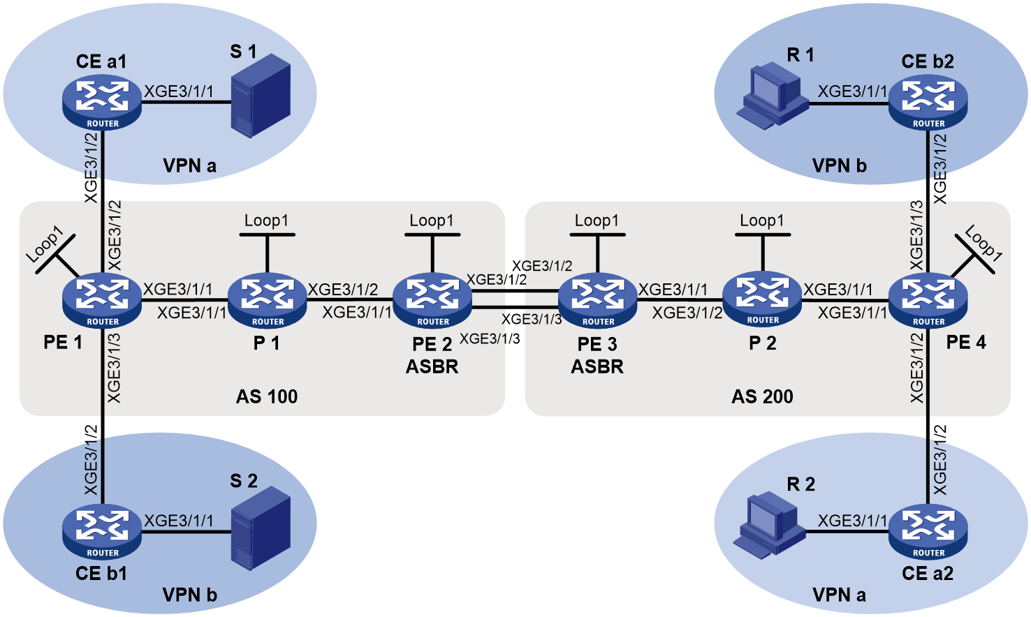
Table 11 Interface and IP address assignment
|
Device |
Interface |
IP address |
Device |
Interface |
IP address |
|
S 1 |
— |
12.1.1.100/24 |
R 1 |
— |
12.4.1.100/24 |
|
S 2 |
— |
12.2.1.100/24 |
R 2 |
— |
12.3.1.100/24 |
|
PE 1 |
XGE3/1/1 |
1011::1/80 |
PE 3 |
XGE3/1/1 |
1041::1/80 |
|
PE 1 |
XGE3/1/2 |
11.1.1.1/24 |
PE 3 |
XGE3/1/2 |
1031::2/80 |
|
PE 1 |
XGE3/1/3 |
11.2.1.1/24 |
PE 3 |
Loop1 |
3.3.3.3/32 3333::3333/128 |
|
PE 1 |
Loop1 |
1.1.1.1/32 1111::1111/128 |
PE 4 |
XGE3/1/1 |
1051::2/80 |
|
PE 2 |
XGE3/1/1 |
1021::2/80 |
PE 4 |
XGE3/1/2 |
11.3.1.1/24 |
|
PE 2 |
XGE3/1/2 |
1031::1/80 |
PE 4 |
XGE3/1/3 |
11.4.1.1/24 |
|
PE 2 |
Loop1 |
2.2.2.2/32 2222::2222/128 |
PE 4 |
Loop1 |
4.4.4.4/32 4444::4444/128 |
|
P 1 |
XGE3/1/1 |
1011::2/80 |
P 2 |
XGE3/1/1 |
1051::1/80 |
|
P 1 |
XGE3/1/2 |
1021::1/80 |
P 2 |
XGE3/1/2 |
1041::2/80 |
|
P 1 |
Loop1 |
5.5.5.5/32 5555::5555/128 |
P 2 |
Loop1 |
6.6.6.6/32 6666::6666/128 |
|
CE a1 |
XGE3/1/1 |
12.1.1.1/24 |
CE b1 |
XGE3/1/1 |
12.2.1.1/24 |
|
CE a1 |
XGE3/1/2 |
11.1.1.2/24 |
CE b1 |
XGE3/1/2 |
11.2.1.2/24 |
|
CE a2 |
XGE3/1/1 |
12.3.1.1/24 |
CE b2 |
XGE3/1/1 |
12.4.1.1/24 |
|
CE a2 |
XGE3/1/2 |
11.3.1.2/24 |
CE b2 |
XGE3/1/2 |
11.4.1.2/24 |
Procedure
1. Configure PE 1:
# Configure a global router ID.
<PE1> system-view
[PE1] router id 1.1.1.1
# Configure BIER.
[PE1] bier
[PE1-bier] sub-domain 0 ipv6
[PE1-bier-sub-domain-0-ipv6] bfr-id 1
[PE1-bier-sub-domain-0-ipv6] bfr-prefix interface LoopBack1
[PE1-bier-sub-domain-0-ipv6] encapsulation-type g-bier bsl 128 max-si 32
[PE1-bier-sub-domain-0-ipv6] g-bier mpra 5001::1
# Configure SRv6.
[PE1] segment-routing ipv6
[PE1-segment-routing-ipv6] encapsulation source-address 11::11
[PE1-segment-routing-ipv6] locator aaa ipv6-prefix 1:2:: 96 static 8
# Configure a multicast service prefix.
[PE1] multicast-service-prefix ms1 ipv6-prefix 1234:1:: 64 service-id-length 10
# Create a VPN instance named a, and configure an RD and route targets for the VPN instance.
[PE1] ip vpn-instance a
[PE1-vpn-instance-a] route-distinguisher 100:1
[PE1-vpn-instance-a] vpn-target 100:1 export-extcommunity
[PE1-vpn-instance-a] vpn-target 100:1 import-extcommunity
[PE1-vpn-instance-a] quit
# Enable IP multicast routing in VPN instance a.
[PE1] multicast routing vpn-instance a
[PE1-mrib-a] quit
# Create a BIER-based MVPN for VPN instance a.
[PE1] multicast-vpn vpn-instance a mode bier
# Create an MVPN IPv4 address family for VPN instance a.
[PE1-mvpn-a] address-family ipv4
# Specify the MVPN source interface for VPN instance a.
[PE1-mvpn-a-ipv4] source loopback 1
# Enable dynamic inclusive tunnel creation and dynamic selective tunnel creation for VPN instance a.
[PE1-mvpn-a-ipv4] inclusive-tunnel dynamic sub-domain 0 bsl 128
[PE1-mvpn-a-ipv4] selective-tunnel dynamic sub-domain 0 bsl 128
[PE1-mvpn-a-ipv4] auto-discovery inter-as
[PE1-mvpn-a-ipv4] tunnel-source multicast-service-prefix ms1 service-id 1
[PE1-mvpn-a-ipv4] quit
[PE1-mvpn-a] quit
# Create a VPN instance named b, and configure an RD and route targets for the VPN instance.
[PE1] ip vpn-instance b
[PE1-vpn-instance-b] route-distinguisher 200:1
[PE1-vpn-instance-b] vpn-target 200:1 export-extcommunity
[PE1-vpn-instance-b] vpn-target 200:1 import-extcommunity
[PE1-vpn-instance-b] quit
# Enable IP multicast routing in VPN instance b.
[PE1] multicast routing vpn-instance b
[PE1-mrib-b] quit
# Create a BIER-based MVPN for VPN instance b.
[PE1] multicast-vpn vpn-instance b mode bier
# Create an MVPN IPv4 address family for VPN instance b.
[PE1-mvpn-b] address-family ipv4
# Specify the MVPN source interface for VPN instance b.
[PE1-mvpn-b-ipv4] source loopback 1
# Enable dynamic inclusive tunnel creation and dynamic selective tunnel creation for VPN instance b.
[PE1-mvpn-b-ipv4] inclusive-tunnel dynamic sub-domain 0 bsl 128
[PE1-mvpn-b-ipv4] selective-tunnel dynamic sub-domain 0 bsl 128
[PE1-mvpn-b-ipv4] auto-discovery inter-as
[PE1-mvpn-b-ipv4] tunnel-source multicast-service-prefix ms1 service-id 2
[PE1-mvpn-b-ipv4] quit
[PE1-mvpn-b] quit
# Assign an IP address to Ten-GigabitEthernet 3/1/1, and enable IS-IS on Ten-GigabitEthernet 3/1/1.
[PE1] interface ten-gigabitethernet 3/1/1
[PE1-Ten-GigabitEthernet3/1/1] ipv6 address 1011::1 24
[PE1-Ten-GigabitEthernet3/1/1] isis ipv6 enable 1
[PE1-Ten-GigabitEthernet3/1/1] quit
# Associate Ten-GigabitEthernet 3/1/2 with VPN instance a, assign an IP address to the interface, and enable PIM-SM on the interface.
[PE1] interface ten-gigabitethernet 3/1/2
[PE1-Ten-GigabitEthernet3/1/2] ip binding vpn-instance a
[PE1-Ten-GigabitEthernet3/1/2] ip address 11.1.1.1 24
[PE1-Ten-GigabitEthernet3/1/2] pim sm
[PE1-Ten-GigabitEthernet3/1/2] quit
# Associate Ten-GigabitEthernet 3/1/3 with VPN instance b, assign an IP address to the interface, and enable PIM-SM on the interface.
[PE1] interface ten-gigabitethernet 3/1/3
[PE1-Ten-GigabitEthernet3/1/3] ip binding vpn-instance b
[PE1-Ten-GigabitEthernet3/1/3] ip address 11.2.1.1 24
[PE1-Ten-GigabitEthernet3/1/3] pim sm
[PE1-Ten-GigabitEthernet3/1/3] quit
# Assign IP addresses to Loopback 1, and enable IS-IS on the interface.
[PE1] interface loopback 1
[PE1-LoopBack1] ip address 1.1.1.1 32
[PE1-LoopBack1] ipv6 address 1111::1111 128
[PE1-LoopBack1] isis ipv6 enable 1
[PE1-LoopBack1] quit
# Configure Ten-GigabitEthernet 3/1/2 as a C-BSR and a C-RP for VPN instance a.
[PE1] pim vpn-instance a
[PE1-pim-a] c-bsr 11.1.1.1
[PE1-pim-a] c-rp 11.1.1.1
[PE1-pim-a] quit
# Configure BGP.
[PE1] bgp 100
[PE1-bgp-default] peer 2222::2222 as-number 100
[PE1-bgp-default] peer 2222::2222 connect-interface loopback 1
[PE1-bgp-default] peer 4444::4444 as-number 200
[PE1-bgp-default] peer 4444::4444 connect-interface loopback 1
[PE1-bgp-default] peer 4444::4444 ebgp-max-hop 10
[PE1–bgp-default] address-family ipv4
[PE1-bgp-default-ipv4] peer 2222::2222 enable
[PE1-bgp-default-ipv4] peer 2222::2222 label-route-capability
[PE1-bgp-default-ipv4] quit
[PE1-bgp-default] address-family ipv4 mvpn
[PE1-bgp-default-mvpn] peer 4444::4444 enable
[PE1-bgp-default-mvpn] quit
[PE1–bgp-default] address-family vpnv4
[PE1–bgp-default-vpnv4] mvpn-advertise-rt-import
[PE1–bgp-default-vpnv4] peer 4444::4444 enable
[PE1–bgp-default-vpnv4] peer 4444::4444 prefix-sid
[PE1–bgp-default-vpnv4] quit
[PE1–bgp-default] ip vpn-instance a
[PE1-bgp-default-a] address-family ipv4
[PE1-bgp-default-ipv4-a] import-route ospf 2
[PE1-bgp-default-ipv4-a] import-route direct
[PE1-bgp-default-ipv4-a] quit
[PE1-bgp-default-a] quit
[PE1–bgp-default] ip vpn-instance b
[PE1-bgp-default-b] address-family ipv4
[PE1-bgp-default-ipv4-b] import-route ospf 3
[PE1-bgp-default-ipv4-b] import-route direct
[PE1-bgp-default-ipv4-b] quit
[PE1-bgp-default-b] quit
[PE1-bgp-default] quit
# Configure IS-IS.
[PE1] isis 1
[PE1-isis-1] is-level level-1
[PE1-isis-1] cost-style wide
[PE1-isis-1] bier enable
[PE1-isis-1] network-entity 10.0000.0000.0001.00
[PE1-isis-1] address-family ipv6 unicast
[PE1-isis-1-ipv6] segment-routing ipv6 locator aaa
# Configure OSPF.
[PE1] ospf 2 vpn-instance a
[PE1-ospf-2] import-route bgp
[PE1-ospf-2] area 0.0.0.0
[PE1-ospf-2-area-0.0.0.0] network 11.1.1.0 0.0.0.255
[PE1-ospf-2-area-0.0.0.0] quit
[PE1-ospf-2] quit
[PE1] ospf 3 vpn-instance b
[PE1-ospf-3] import-route bgp
[PE1-ospf-3] area 0.0.0.0
[PE1-ospf-3-area-0.0.0.0] network 11.2.1.0 0.0.0.255
[PE1-ospf-3-area-0.0.0.0] quit
[PE1-ospf-3] quit
2. Configure PE 2:
# Configure a global router ID.
<PE2> system-view
[PE2] router id 2.2.2.2
# Configure BIER.
[PE2] bier
[PE2-bier] sub-domain 0 ipv6
[PE2-bier-sub-domain-0-ipv6] bfr-id 2
[PE2-bier-sub-domain-0-ipv6] bfr-prefix interface LoopBack1
[PE2-bier-sub-domain-0-ipv6] encapsulation-type g-bier bsl 128 max-si 32
[PE2-bier-sub-domain-0-ipv6] g-bier mpra 5002::1
# Configure SRv6.
[PE2] segment-routing ipv6
[PE2-segment-routing-ipv6] encapsulation source-address 22::22
[PE2-segment-routing-ipv6] locator aaa ipv6-prefix 2:2:: 96 static 8
# Assign an IP address to Ten-GigabitEthernet 3/1/1, and enable IS-IS on the interface.
[PE2] interface ten-gigabitethernet 3/1/1
[PE2-Ten-GigabitEthernet3/1/1] ipv6 address 1021::2 80
[PE2-Ten-GigabitEthernet3/1/1] isis ipv6 enable 1
[PE2-Ten-GigabitEthernet3/1/1] quit
# Assign an IP address to Ten-GigabitEthernet 3/1/2.
[PE2] interface ten-gigabitethernet 3/1/2
[PE2-Ten-GigabitEthernet3/1/2] ipv6 address 1031::1 80
[PE2-Ten-GigabitEthernet3/1/2] quit
# Assign IP addresses to Loopback 1 and enable IS-IS on the interface.
[PE2] interface loopback 1
[PE2-LoopBack1] ip address 1.1.1.2 32
[PE2-LoopBack1] ipv6 address 2222::2222 80
[PE2-LoopBack1] isis ipv6 enable 1
[PE2-LoopBack1] quit
# Configure BGP.
[PE2] bgp 100
[PE2-bgp-default] peer 1111::1111 as-number 100
[PE2-bgp-default] peer 1111::1111 connect-interface loopback 1
[PE2-bgp-default] peer 1031::2 as-number 200
[PE2-bgp-default] address-family ipv6
[PE2-bgp-default-ipv6] peer 1111::1111 enable
[PE2-bgp-default-ipv6] peer 1031::2 enable
[PE2-bgp-default-ipv6] import-route isisv6 1
[PE2-bgp-default-ipv6] segment-routing ipv6 locator aaa
[PE2-bgp-default-ipv6] bier enable
[PE2-bgp-default-ipv6] bier bfr-prefix proxy
[PE2-bgp-default-ipv6] import-bier isisv6 1
[PE2-bgp-default-ipv6] import-route isisv6
[PE2-bgp-default-ipv6] quit
[PE2–bgp-default] quit
# Configure IS-IS.
[PE2] isis 1
[PE2-isis-1] is-level level-1
[PE2-isis-1] cost-style wide
[PE2-isis-1] bier enable
[PE2-isis-1] network-entity 10.0000.0000.0002.00
[PE2-isis-1] address-family ipv6 unicast
[PE2-isis-1-ipv6] segment-routing ipv6 locator aaa
[PE2-isis-1-ipv6] import-bier bgp4+
3. Configure PE 3:
# Configure a global router ID.
<PE3> system-view
[PE3] router id 3.3.3.3
# Configure BIER.
[PE3] bier
[PE3-bier] sub-domain 0 ipv6
[PE3-bier-sub-domain-0-ipv6] bfr-id 3
[PE3-bier-sub-domain-0-ipv6] bfr-prefix interface LoopBack1
[PE3-bier-sub-domain-0-ipv6] encapsulation-type g-bier bsl 128 max-si 32
[PE3-bier-sub-domain-0-ipv6] g-bier mpra 5003::1
# Configure SRv6.
[PE3] segment-routing ipv6
[PE3-segment-routing-ipv6] encapsulation source-address 33::33
[PE3-segment-routing-ipv6] locator aaa ipv6-prefix 3:2:: 96 static 8
# Assign an IPv6 address to Ten-GigabitEthernet 3/1/1, and enable IS-IS on the interface.
[PE3] interface ten-gigabitethernet 3/1/1
[PE3-Ten-GigabitEthernet3/1/1] ipv6 address 1041::1 80
[PE3-Ten-GigabitEthernet3/1/1] isis ipv6 enable 1
[PE3-Ten-GigabitEthernet3/1/1] quit
# Assign an Iv6 address to Ten-GigabitEthernet 3/1/2.
[PE3] interface ten-gigabitethernet 3/1/2
[PE3-Ten-GigabitEthernet3/1/2] ipv6 address 1031::2 80
[PE3-Ten-GigabitEthernet3/1/2] quit
# Assign IP addresses to Loopback 1 and enable IS-IS on the interface.
[PE3] interface loopback 1
[PE3-LoopBack1] ip address 3.3.3.3 32
[PE3-LoopBack1] ipv6 address 3333::3333 128
[PE3-LoopBack1] isis ipv6 enable 1
[PE3-LoopBack1] quit
# Configure BGP.
[PE3] bgp 200
[PE3-bgp-default] peer 4444::4444 as-number 200
[PE3-bgp-default] peer 4444::4444 connect-interface loopback 1
[PE3-bgp-default] peer 1031::1 as-number 100
[PE3-bgp-default] address-family ipv6
[PE3-bgp-default-ipv6] peer 4444::4444 enable
[PE3-bgp-default-ipv6] peer 1031::1 enable
[PE3-bgp-default-ipv6] import-route isisv6 1
[PE3-bgp-default-ipv6] segment-routing ipv6 locator aaa
[PE3-bgp-default-ipv6] bier enable
[PE3-bgp-default-ipv6] bier bfr-prefix proxy
[PE3-bgp-default-ipv6] import-bier isisv6 1
[PE3-bgp-default-ipv6] import-route isisv6
[PE3-bgp-default-ipv6] quit
[PE3–bgp-default] quit
# Configure IS-IS.
[PE3] isis 1
[PE3-isis-1] is-level level-1
[PE3-isis-1] cost-style wide
[PE3-isis-1] bier enable
[PE3-isis-1] network-entity 10.0000.0000.0003.00
[PE3-isis-1] address-family ipv6 unicast
[PE3-isis-1-ipv6] segment-routing ipv6 locator aaa
[PE3-isis-1-ipv6] import-bier bgp4+
4. Configure PE 4:
# Configure a global router ID, and enable IP multicast routing.
<PE4> system-view
[PE4] router id 4.4.4.4
[PE4] multicast routing
[PE4-mrib] quit
# Configure BIER.
[PE4] bier
[PE4-bier] sub-domain 0 ipv6
[PE4-bier-sub-domain-0-ipv6] bfr-id 4
[PE4-bier-sub-domain-0-ipv6] bfr-prefix interface LoopBack1
[PE4-bier-sub-domain-0-ipv6] encapsulation-type g-bier bsl 128 max-si 32
[PE4-bier-sub-domain-0-ipv6] g-bier mpra 5004::1
# Configure SRv6.
[PE4] segment-routing ipv6
[PE4-segment-routing-ipv6] encapsulation source-address 44::44
[PE4-segment-routing-ipv6] locator aaa ipv6-prefix 4:2:: 96 static 8
# Configure a multicast service prefix.
[PE4] multicast-service-prefix ms1 ipv6-prefix 1234:4:: 64 service-id-length 10
# Create a VPN instance named a, and configure an RD and route targets for the VPN instance.
[PE4] ip vpn-instance a
[PE4-vpn-instance-a] route-distinguisher 300:1
[PE4-vpn-instance-a] vpn-target 100:1 export-extcommunity
[PE4-vpn-instance-a] vpn-target 100:1 import-extcommunity
[PE4-vpn-instance-a] quit
# Enable IP multicast routing for VPN instance a.
[PE4] multicast routing vpn-instance a
[PE4-mrib-a] quit
# Create a BIER-based MVPN for VPN instance a.
[PE4] multicast-vpn vpn-instance a mode bier
# Create an MVPN IPv4 address family for VPN instance a.
[PE4-mvpn-a] address-family ipv4
# Specify the MVPN source interface for VPN instance a.
[PE4-mvpn-a-ipv4] source loopback 1
# Enable dynamic inclusive tunnel creation and dynamic selective tunnel creation for VPN instance a.
[PE4-mvpn-a-ipv4] inclusive-tunnel dynamic sub-domain 0 bsl 128
[PE4-mvpn-a-ipv4] selective-tunnel dynamic sub-domain 0 bsl 128
[PE4-mvpn-a-ipv4] tunnel-source multicast-service-prefix ms1 service-id 1
[PE4-mvpn-a-ipv4] quit
[PE4-mvpn-a] quit
# Create a VPN instance named b, and configure an RD and route targets for the VPN instance.
[PE4] ip vpn-instance b
[PE4-vpn-instance-b] route-distinguisher 400:1
[PE4-vpn-instance-b] vpn-target 200:1 export-extcommunity
[PE4-vpn-instance-b] vpn-target 200:1 import-extcommunity
[PE4-vpn-instance-b] quit
# Enable IP multicast routing for VPN instance b.
[PE4] multicast routing vpn-instance b
[PE4-mrib-b] quit
# Create a BIER-based MVPN for VPN instance b.
[PE4] multicast-vpn vpn-instance b mode bier
# Create an MVPN IPv4 address family for VPN instance b.
[PE4-mvpn-b] address-family ipv4
# Specify the MVPN source interface for VPN instance b.
[PE4-mvpn-b-ipv4] source loopback 1
# Enable dynamic inclusive tunnel creation and dynamic selective tunnel creation for VPN instance b.
[PE4-mvpn-b-ipv4] inclusive-tunnel dynamic sub-domain 0 bsl 128
[PE4-mvpn-b-ipv4] selective-tunnel dynamic sub-domain 0 bsl 128
[PE4-mvpn-b-ipv4] tunnel-source multicast-service-prefix ms1 service-id 2
[PE4-mvpn-b-ipv4] quit
[PE4-mvpn-b] quit
# Assign an IPv6 address to Ten-GigabitEthernet 3/1/1, and enable IS-IS on the interface.
[PE4] interface ten-gigabitethernet 3/1/1
[PE4-Ten-GigabitEthernet3/1/1] ipv6 address 1051::2 80
[PE4-Ten-GigabitEthernet3/1/1] isis ipv6 enable 1
[PE4-Ten-GigabitEthernet3/1/1] quit
# Associate Ten-GigabitEthernet 3/1/2 with VPN instance a, assign an IP address to the interface, and enable PIM-SM on the interface.
[PE4] interface ten-gigabitethernet 3/1/2
[PE4-Ten-GigabitEthernet3/1/2] ip binding vpn-instance a
[PE4-Ten-GigabitEthernet3/1/2] ip address 11.3.1.1 24
[PE4-Ten-GigabitEthernet3/1/2] pim sm
[PE4-Ten-GigabitEthernet3/1/2] quit
# Associate Ten-GigabitEthernet 3/1/3 with VPN instance b, assign an IP address to the interface, and enable PIM-SM on the interface.
[PE4] interface ten-gigabitethernet 3/1/3
[PE4-Ten-GigabitEthernet3/1/3] ip binding vpn-instance b
[PE4-Ten-GigabitEthernet3/1/3] ip address 11.4.1.1 24
[PE4-Ten-GigabitEthernet3/1/3] pim sm
[PE4-Ten-GigabitEthernet3/1/3] quit
# Assign an IP address to Loopback 1.
[PE4] interface loopback 1
[PE4-LoopBack1] ip address 4.4.4.4 32
[PE4-LoopBack1] quit
# Configure BGP.
[PE4] bgp 200
[PE4-bgp-default] peer 3333::3333 as-number 200
[PE4-bgp-default] peer 3333::3333 connect-interface loopback 1
[PE4-bgp-default] peer 1111::1111 as-number 100
[PE4-bgp-default] peer 1111::1111 ebgp-max-hop 10
[PE4-bgp-default] peer 1111::1111 connect-interface loopback 1
[PE4-bgp-default] address-family ipv4
[PE4-bgp-default-ipv4] peer 3333::3333 enable
[PE4-bgp-default-ipv4] peer 3333::3333 label-route-capability
[PE4-bgp-default-ipv4] quit
[PE4–bgp-default] address-family ipv4 mvpn
[PE4–bgp-default-mvpn] peer 1111::1111 enable
[PE4–bgp-default-mvpn] quit
[PE4–bgp-default] address-family vpnv4
[PE4–bgp-default-vpnv4]mvpn-advertise-rt-import
[PE4–bgp-default-vpnv4] peer 1111::1111 enable
[PE4–bgp-default-vpnv4] peer 1111::1111 prefix-sid
[PE4–bgp-default-vpnv4] quit
[PE4–bgp-default] ip vpn-instance a
[PE4-bgp-default-a] address-family ipv4
[PE4-bgp-default-ipv4-a] import-route ospf 2
[PE4-bgp-default-ipv4-a] import-route direct
[PE4-bgp-default-ipv4-a] quit
[PE4-bgp-default-a] quit
[PE4–bgp-default] ip vpn-instance b
[PE4-bgp-default-b] address-family ipv4
[PE4-bgp-default-ipv4-b] import-route ospf 3
[PE4-bgp-default-ipv4-b] import-route direct
[PE4-bgp-default-ipv4-b] quit
[PE4-bgp-default-b] quit
[PE4–bgp-default] quit
# Configure IS-IS.
[PE4] isis 1
[PE4-isis-1] is-level level-1
[PE4-isis-1] cost-style wide
[PE4-isis-1] bier enable
[PE4-isis-1] network-entity 10.0000.0000.0004.00
[PE4-isis-1] address-family ipv6 unicast
[PE4-isis-1-ipv6] segment-routing ipv6 locator aaa
# Configure OSPF.
[PE4] ospf 2 vpn-instance a
[PE4-ospf-2] import-route bgp 200
[PE4-ospf-2] area 0.0.0.0
[PE4-ospf-2-area-0.0.0.0] network 11.3.1.0 0.0.0.255
[PE4-ospf-2-area-0.0.0.0] quit
[PE4-ospf-2] quit
[PE4] ospf 3 vpn-instance b
[PE4-ospf-3] import-route bgp 200
[PE4-ospf-3] area 0.0.0.0
[PE4-ospf-3-area-0.0.0.0] network 11.4.1.0 0.0.0.255
[PE4-ospf-3-area-0.0.0.0] quit
[PE4-ospf-3] quit
5. Configure P 1:
# Configure BIER.
[P1] bier
[P1-bier] sub-domain 0 ipv6
[P1-bier-sub-domain-0-ipv6] bfr-id 5
[P1-bier-sub-domain-0-ipv6] bfr-prefix interface LoopBack1
[P1-bier-sub-domain-0-ipv6] encapsulation-type g-bier bsl 128 max-si 32
[P1-bier-sub-domain-0-ipv6] g-bier mpra 5005::1
# Configure SRv6.
[P1] segment-routing ipv6
[P1-segment-routing-ipv6] encapsulation source-address 55::55
[P1-segment-routing-ipv6] locator aaa ipv6-prefix 5:2:: 96 static 8
# Assign an IP address to Ten-GigabitEthernet 3/1/1, and enable IS-IS on the interface.
[P1] interface ten-gigabitethernet 3/1/1
[P1-Ten-GigabitEthernet3/1/1] ipv6 address 1011::2 80
[P1-Ten-GigabitEthernet3/1/1] isis ipv6 enable 1
[P1-Ten-GigabitEthernet3/1/1] quit
# Assign an IP address to Ten-GigabitEthernet 3/1/2, and enable IS-IS on the interface.
[P1] interface ten-gigabitethernet 3/1/2
[P1-Ten-GigabitEthernet3/1/2] ipv6 address 1021::1 80
[P1-Ten-GigabitEthernet3/1/2] isis ipv6 enable 1
[P1-Ten-GigabitEthernet3/1/2] quit
# Assign IP addresses to Loopback 1 and enable IS-IS on the interface.
[P1] interface loopback 1
[P1-LoopBack1] ip address 5.5.5.5 32
[P1-LoopBack1] ipv6 address 5555::5555 128
[P1-LoopBack1] isis ipv6 enable 1
[P1-LoopBack1] quit
# Configure IS-IS.
[P1] isis 1
[P1-isis-1] is-level level-1
[P1-isis-1] cost-style wide
[P1-isis-1] bier enable
[P1-isis-1] network-entity 10.0000.0000.0005.00
[P1-isis-1] address-family ipv6 unicast
[P1-isis-1-ipv6] segment-routing ipv6 locator aaa
[P1-isis-1-ipv6] quit
[P1-isis-1] quit
6. Configure P 2:
# Configure BIER.
[P2] bier
[P2-bier] sub-domain 0 ipv6
[P2-bier-sub-domain-0-ipv6] bfr-id 6
[P2-bier-sub-domain-0-ipv6] bfr-prefix interface LoopBack1
[P2-bier-sub-domain-0-ipv6] encapsulation-type g-bier bsl 128 max-si 32
[P2-bier-sub-domain-0-ipv6] g-bier mpra 5006::1
# Configure SRv6.
[P2] segment-routing ipv6
[P2-segment-routing-ipv6] encapsulation source-address 66::66
[P2-segment-routing-ipv6] locator aaa ipv6-prefix 6:2:: 96 static 8
# Assign an IPv6 address to Ten-GigabitEthernet 3/1/1, and enable IS-IS on the interface.
[P2] interface ten-gigabitethernet 3/1/1
[P2-Ten-GigabitEthernet3/1/1] ipv6 address 1051::1 80
[P2-Ten-GigabitEthernet3/1/1] isis ipv6 enable 1
[P2-Ten-GigabitEthernet3/1/1] quit
# Assign an IPv6 address to Ten-GigabitEthernet 3/1/2, and enable IS-IS on the interface.
[P2] interface ten-gigabitethernet 3/1/2
[P2-Ten-GigabitEthernet3/1/2] ipv6 address 1041::2 80
[P2-Ten-GigabitEthernet3/1/2] isis ipv6 enable 1
[P2-Ten-GigabitEthernet3/1/2] quit
# Assign IP addresses to Loopback 1 and enable IS-IS on the interface.
[P2] interface loopback 1
[P2-LoopBack1] ip address 6.6.6.6 32
[P2-LoopBack1] ipv6 address 6666::6666 128
[P2-LoopBack1] isis ipv6 enable 1
[P2-LoopBack1] quit
# Configure IS-IS.
[P2] isis 1
[P2-isis-1] is-level level-1
[P2-isis-1] cost-style wide
[P2-isis-1] bier enable
[P2-isis-1] network-entity 10.0000.0000.0006.00
[P2-isis-1] address-family ipv6 unicast
[P2-isis-1-ipv6] segment-routing ipv6 locator aaa
[P2-isis-1-ipv6] quit
[P2-isis-1] quit
7. Configure CE a1:
# Enable IP multicast routing.
<CEa1> system-view
[CEa1] multicast routing
[CEa1-mrib] quit
# Assign an IP address to Ten-GigabitEthernet 3/1/1, and enable PIM-SM on the interface.
[CEa1] interface ten-gigabitethernet 3/1/1
[CEa1-Ten-GigabitEthernet3/1/1] ip address 12.1.1.1 24
[CEa1-Ten-GigabitEthernet3/1/1] pim sm
[CEa1-Ten-GigabitEthernet3/1/1] quit
# Assign an IP address to Ten-GigabitEthernet 3/1/2, and enable PIM-SM on the interface.
[CEa1] interface ten-gigabitethernet 3/1/2
[CEa1-Ten-GigabitEthernet3/1/2] ip address 11.1.1.2 24
[CEa1-Ten-GigabitEthernet3/1/2] pim sm
[CEa1-Ten-GigabitEthernet3/1/2] quit
# Configure OSPF.
[CEa1] ospf 1
[CEa1-ospf-1] area 0.0.0.0
[CEa1-ospf-1-area-0.0.0.0] network 12.1.1.0 0.0.0.255
[CEa1-ospf-1-area-0.0.0.0] network 11.1.1.0 0.0.0.255
[CEa1-ospf-1-area-0.0.0.0] quit
[CEa1-ospf-1] quit
8. Configure CE b1:
# Enable IP multicast routing.
<CEb1> system-view
[CEb1] multicast routing
[CEb1-mrib] quit
# Assign an IP address to Ten-GigabitEthernet 3/1/1, and enable PIM-SM on the interface.
[CEb1] interface ten-gigabitethernet 3/1/1
[CEb1-Ten-GigabitEthernet3/1/1] ip address 12.2.1.1 24
[CEb1-Ten-GigabitEthernet3/1/1] pim sm
[CEb1-Ten-GigabitEthernet3/1/1] quit
# Assign an IP address to Ten-GigabitEthernet 3/1/2, and enable PIM-SM on the interface.
[CEb1] interface ten-gigabitethernet 3/1/2
[CEb1-Ten-GigabitEthernet3/1/2] ip address 11.2.1.2 24
[CEb1-Ten-GigabitEthernet3/1/2] pim sm
[CEb1-Ten-GigabitEthernet3/1/2] quit
# Configure OSPF.
[CEb1] ospf 1
[CEb1-ospf-1] area 0.0.0.0
[CEb1-ospf-1-area-0.0.0.0] network 12.2.1.0 0.0.0.255
[CEb1-ospf-1-area-0.0.0.0] network 11.2.1.0 0.0.0.255
[CEb1-ospf-1-area-0.0.0.0] quit
[CEb1-ospf-1] quit
9. Configure CE a2:
# Enable IP multicast routing.
<CEa2> system-view
[CEa2] multicast routing
[CEa2-mrib] quit
# Assign an IP address to Ten-GigabitEthernet 3/1/1, and enable IGMP on the interface.
[CEa2] interface ten-gigabitethernet 3/1/1
[CEa2-Ten-GigabitEthernet3/1/1] ip address 12.3.1.1 24
[CEa2-Ten-GigabitEthernet3/1/1] igmp enable
[CEa2-Ten-GigabitEthernet3/1/1] quit
# Assign an IP address to Ten-GigabitEthernet 3/1/2, and enable PIM-SM on the interface.
[CEa2] interface ten-gigabitethernet 3/1/2
[CEa2-Ten-GigabitEthernet3/1/2] ip address 11.3.1.2 24
[CEa2-Ten-GigabitEthernet3/1/2] pim sm
[CEa2-Ten-GigabitEthernet3/1/2] quit
# Configure OSPF.
[CEa2] ospf 1
[CEa2-ospf-1] area 0.0.0.0
[CEa2-ospf-1-area-0.0.0.0] network 12.3.1.0 0.0.0.255
[CEa2-ospf-1-area-0.0.0.0] network 11.3.1.0 0.0.0.255
[CEa2-ospf-1-area-0.0.0.0] quit
[CEa2-ospf-1] quit
10. Configure CE b2:
# Enable IP multicast routing.
<CEb2> system-view
[CEb2] multicast routing
[CEb2-mrib] quit
# Assign an IP address to Ten-GigabitEthernet 3/1/1, and enable IGMP on the interface.
[CEb2] interface ten-gigabitethernet 3/1/1
[CEb2-Ten-GigabitEthernet3/1/1] ip address 12.4.1.1 24
[CEb2-Ten-GigabitEthernet3/1/1] igmp enable
[CEb2-Ten-GigabitEthernet3/1/1] igmp version 3
[CEb2-Ten-GigabitEthernet3/1/1] quit
# Assign an IP address to Ten-GigabitEthernet 3/1/2, and enable PIM-SM on the interface.
[CEb2] interface ten-gigabitethernet 3/1/2
[CEb2-Ten-GigabitEthernet3/1/2] ip address 11.4.1.2 24
[CEb2-Ten-GigabitEthernet3/1/2] pim sm
[CEb2-Ten-GigabitEthernet3/1/2] quit
# Configure OSPF.
[CEb2] ospf 1
[CEb2-ospf-1] area 0.0.0.0
[CEb2-ospf-1-area-0.0.0.0] network 12.4.1.0 0.0.0.255
[CEb2-ospf-1-area-0.0.0.0] network 11.4.1.0 0.0.0.255
[CEb2-ospf-1-area-0.0.0.0] quit
[CEb2-ospf-1] quit
Verifying the configuration
# Display information about the BIER inclusive tunnel for VPN instance a on PE 1.
[PE1] display multicast-vpn vpn-instance a inclusive-tunnel local
Tunnel type: BIER
Tunnel interface: BIERVOif0
Tunnel identifier: BIER <0x0, 0x1, 5001::>
Tunnel state: Up
Flags: 0x10
Sub-domain ID/BSL: 0/128
BFR-ID: 1
BFR prefix: 5001::
Multicast service prefix:
Prefix length ID length ID offset MS Flags
64 10 0 0
Root: 5001:: (local)
Leafs:
1: BFR-ID: 4 BFR prefix: 5004::
Uptime: 00:01:00 Originating router: 5004::
# Display information about BIER selective tunnels for VPN instance a on PE 1.
[PE1] display multicast-vpn vpn-instance a selective-tunnel local
Total 1 selective tunnels in using
Total 0 selective tunnel in creating
Tunnel type: BIER
Tunnel interface: BIERVOif2
Tunnel identifier: BIER <0x0, 0x1, 5001::>
Tunnel state: Up
Flags: 0x10
Sub-domain ID/BSL: 0/128
BFR-ID: 1
BFR prefix: 5001::
Multicast service prefix:
Prefix length ID length ID offset MS Flags
64 10 0 0
Root: 4001:: (local)
Leafs:
1: BFR-ID: 4 BFR prefix: 5004::
Uptime: 00:10:01 Originating router: 5004::
# Display C-multicast A-D route information for VPN instance a on PE 1.
[PE1] display multicast-vpn vpn-instance a c-multicast routing-table
Total 0 (*, G) entry; 1 (S, G) entry
(12.1.1.100, 225.0.0.1)
CreateTime: 02:54:43
Tunnel Information: BIERVOif2
# Display information about the PIM-SM routing entries for VPN instance a on PE 1.
[PE1] display pim vpn-instance a routing-table
Total 0 (*, G) entries; 1 (S, G) entries
(12.1.1.100, 225.0.0.1)
RP: 11.1.1.1 (local)
Protocol: pim-sm, Flag: SPT 2MSDP ACT RC SRC-ACT 2MVPN
UpTime: 00:00:43
Upstream interface: Ten-GigabitEthernet3/1/2
Upstream neighbor: 11.1.1.2
RPF prime neighbor: 11.1.1.2
Downstream interface information:
Total number of downstream interfaces: 1
1: BIERVOif2
Protocol: MD, UpTime: 00:00:30, Expires: -
# Display information about the BIER inclusive tunnel for VPN instance b on PE 1.
[PE1]display multicast-vpn vpn-instance b inclusive-tunnel local
Tunnel type: BIER
Tunnel interface: BIERVOif3
Tunnel identifier: BIER <0x0, 0x1, 5001::>
Tunnel state: Up
Flags: 0x10
Sub-domain ID/BSL: 0/128
BFR-ID: 1
BFR prefix: 5001::
Multicast service prefix:
Prefix length ID length ID offset MS Flags
64 10 0 0
Root: 5001:: (local)
Leafs:
1: BFR-ID: 4 BFR prefix: 5004::
Uptime: 00:01:00 Originating router: 5004::
# Display information about BIER selective tunnels for VPN instance b on PE 1.
[PE1]display multicast-vpn vpn-instance b selective-tunnel local
Total 1 selective tunnels in using
Total 0 selective tunnel in creating
Tunnel type: BIER
Tunnel interface: BIERVOif4
Tunnel identifier: BIER <0x0, 0x1, 5001::>
Tunnel state: Up
Flags: 0x10
Sub-domain ID/BSL: 0/128
BFR-ID: 1
BFR prefix: 5001::
Multicast service prefix:
Prefix length ID length ID offset MS Flags
64 10 0 0
Root: 4001:: (local)
Leafs:
1: BFR-ID: 4 BFR prefix: 5004::
Uptime: 00:10:01 Originating router: 5004::
# Display information about the PIM-SSM routing entries for VPN instance b on PE 1.
[PE1] display pim vpn-instance b routing-table
Total 0 (*, G) entries; 1 (S, G) entries
(12.2.1.100, 232.0.0.0)
Protocol: pim-ssm, Flag: RC
UpTime: 00:26:06
Upstream interface: Ten-GigabitEthernet3/1/3
Upstream neighbor: 11.2.1.2
RPF prime neighbor: 11.2.1.2
Downstream interface information:
Total number of downstream interfaces: 1
1: BIERVOif4
Protocol: MD, UpTime: 00:25:56, Expires: -
# Display information about the BIER inclusive tunnel for VPN instance a on PE 4.
[PE4] display multicast-vpn vpn-instance a inclusive-tunnel remote
Total 1 inclusive tunnel
Tunnel type: BIER
Tunnel state: --
Flags: 0x0
Sub-domain ID/BSL: 0/128
BFR-ID: 1
BFR prefix: 5001::
Root: 5001::
Leaf:
1: BFR-ID: 4 BFR prefix: 5004::
Uptime: -- Originating router: 5004::
# Display information about BIER selective tunnels for VPN instance a on PE 4.
[PE4] display multicast-vpn vpn-instance a selective-tunnel remote
Tunnel type: BIER
Tunnel state: --
Flags: 0x0
Sub-domain ID/BSL: 0/128
BFR-ID: 1
BFR prefix: 5001::
Root: 5001::
Leaf:
1: BFR-ID: 4 BFR prefix: 5004::
Uptime: -- Originating router: 5004::
# Display information about the BIER inclusive tunnel for VPN instance b on PE 4.
[PE4] display multicast-vpn vpn-instance b inclusive-tunnel remote
Total 1 inclusive tunnel
Tunnel type: BIER
Tunnel state: --
Flags: 0x0
Sub-domain ID/BSL: 0/128
BFR-ID: 1
BFR prefix: 5001::
Root: 5001::
Leaf:
1: BFR-ID: 4 BFR prefix: 5004::
Uptime: -- Originating router: 5004::
# Display information about BIER selective tunnels for VPN instance b on PE 4.
[PE4] display multicast-vpn vpn-instance b selective-tunnel remote
Tunnel type: BIER
Tunnel state: --
Flags: 0x0
Sub-domain ID/BSL: 0/128
BFR-ID: 1
BFR prefix: 5001::
Root: 5001::
Leaf:
1: BFR-ID: 4 BFR prefix: 5004::
Uptime: -- Originating router: 5004::
Example: Configuring receiver-PE-based MVPN extranet
Network configuration
As shown in Figure 35, configure MVPN extranet to meet the following requirements:
|
Item |
Network configuration |
|
Multicast sources and receivers |
· In VPN instance a, S 1 is a multicast source. · In VPN instance b, R 1 is a receiver. · For VPN instance a, the default group is 239.1.1.1, and the data group range is 225.2.2.0 to 225.2.2.15. |
|
VPN instances to which PE interfaces belong |
· PE 1: Ten-GigabitEthernet3/1/1 belongs to VPN instance a. Ten-GigabitEthernet3/1/2 and Loopback 0 belong to the public network instance. · PE 2: Ten-GigabitEthernet3/1/2 belongs to VPN instance b. Ten-GigabitEthernet3/1/1 and Loopback 0 belong to the public network instance. |
|
Unicast routing protocols and MPLS |
· Configure OSPF on the public network and configure RIP between PEs and CEs. · Establish BGP peer connections between PE 1 and PE 2 on their respective Loopback 0. · Configure MPLS on the public network. |
|
IP multicast routing |
· Enable IP multicast routing on the P device. · Enable IP multicast routing for the public network on PE 1 and PE 2. · Enable IP multicast routing for VPN instance a on PE 1. · Enable IP multicast routing for VPN instance b on PE 2. · Enable IP multicast routing on CE 1 and CE 2. |
|
IGMPv2 |
Enable IGMPv2 on Ten-GigabitEthernet3/1/2 of CE 2. |
|
PIM-SM |
Enable PIM-SM on the public network and for VPN instances a and b: · Enable PIM-SM on all interfaces of the P device. · Enable PIM-SM on all public and private network interfaces of PE 1 and PE 2. · Enable PIM-SM on all interfaces that do not have attached receiver hosts on CE 1 and CE 2. · Configure Loopback 0 of the P device as a C-BSR and a C-RP for the public network to provide services for all multicast groups. · Configure Loopback 1 of CE 1 as a C-BSR and a C-RP for VPN instance a to provide services for all multicast groups. · Configure Loopback 1 of PE 2 as a C-BSR and a C-RP for VPN instance b to provide services for all multicast groups. |
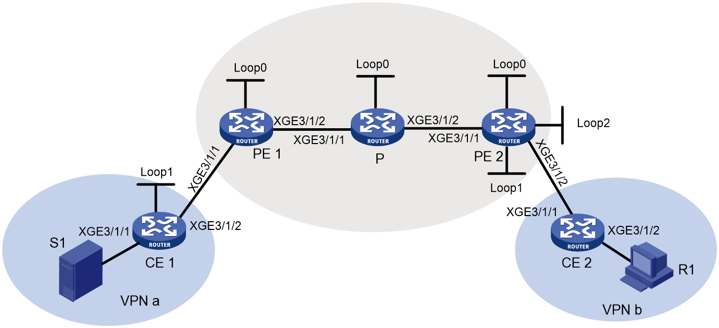
Table 12 Interface and IP address assignment
|
Device |
Interface |
IP address |
Device |
Interface |
IP address |
|
S 1 |
— |
10.110.7.2/24 |
PE 2 |
XGE3/1/1 |
192.168.7.1/24 |
|
R 1 |
— |
10.110.11.2/24 |
PE 2 |
XGE3/1/2 |
10.110.3.2/24 |
|
P |
XGE3/1/1 |
192.168.6.1/24 |
PE 2 |
Loop0 |
1.1.1.2/32 |
|
P |
XGE3/1/2 |
192.168.7.2/24 |
PE 2 |
Loop1 |
20.20.20.20/32 |
|
P |
Loop0 |
2.2.2.2/32 |
PE 2 |
Loop2 |
100.100.100.100/32 |
|
PE 1 |
XGE3/1/1 |
10.110.2.1/24 |
CE 1 |
XGE3/1/1 |
10.110.7.1/24 |
|
PE 1 |
XGE3/1/2 |
192.168.6.2/24 |
CE 1 |
XGE3/1/2 |
10.110.2.2/24 |
|
PE 1 |
Loop0 |
1.1.1.1/32 |
CE 1 |
Loop1 |
11.11.11.11/32 |
|
|
|
|
CE 2 |
XGE3/1/1 |
10.110.3.1/24 |
|
|
|
|
CE 2 |
XGE3/1/2 |
10.110.11.1/24 |
Procedure
1. Configure PE 1:
# Configure a global router ID, and enable IP multicast routing on the public network.
<PE1> system-view
[PE1] router id 1.1.1.1
[PE1] multicast routing
[PE1-mrib] quit
# Configure an LSR ID, and enable LDP globally.
[PE1] mpls lsr-id 1.1.1.1
[PE1] mpls ldp
[PE1-ldp] quit
# Create a VPN instance named a, and configure an RD and route targets for the VPN instance.
[PE1] ip vpn-instance a
[PE1-vpn-instance-a] route-distinguisher 100:1
[PE1-vpn-instance-a] vpn-target 100:1 export-extcommunity
[PE1-vpn-instance-a] vpn-target 100:1 import-extcommunity
[PE1-vpn-instance-a] quit
# Enable IP multicast routing for VPN instance a.
[PE1] multicast routing vpn-instance a
[PE1-mrib-a] quit
# Create an MDT-based MVPN for VPN instance a.
[PE1] multicast-vpn vpn-instance a mode mdt
# Create an MVPN IPv4 address family for VPN instance a.
[PE1-mvpn-vpn-instance-a] address-family ipv4
# Specify the default group, the MVPN source interface, and the data group range for VPN instance a.
[PE1-mvpn-vpn-instance-a-ipv4] default-group 239.1.1.1
[PE1-mvpn-vpn-instance-a-ipv4] source loopback 0
[PE1-mvpn-vpn-instance-a-ipv4] data-group 225.2.2.0 28
[PE1-mvpn-vpn-instance-a-ipv4] quit
[PE1-mvpn-vpn-instance-a] quit
# Assign an IP address to Ten-GigabitEthernet 3/1/2, and enable PIM-SM, MPLS, and IPv4 LDP on the interface.
[PE1] interface ten-gigabitethernet 3/1/2
[PE1-Ten-GigabitEthernet3/1/2] ip address 192.168.6.2 24
[PE1-Ten-GigabitEthernet3/1/2] pim sm
[PE1-Ten-GigabitEthernet3/1/2] mpls enable
[PE1-Ten-GigabitEthernet3/1/2] mpls ldp enable
[PE1-Ten-GigabitEthernet3/1/2] quit
# Associate Ten-GigabitEthernet 3/1/1 with VPN instance a, assign an IP address to the interface and enable PIM-SM on the interface.
[PE1] interface ten-gigabitethernet 3/1/1
[PE1-Ten-GigabitEthernet3/1/1] ip binding vpn-instance a
[PE1-Ten-GigabitEthernet3/1/1] ip address 10.110.2.1 24
[PE1-Ten-GigabitEthernet3/1/1] pim sm
[PE1-Ten-GigabitEthernet3/1/1] quit
# Assign an IP address to Loopback 0, and enable PIM-SM on the interface.
[PE1] interface loopback 0
[PE1-LoopBack0] ip address 1.1.1.1 32
[PE1-LoopBack0] pim sm
[PE1-LoopBack0] quit
# Configure BGP.
[PE1] bgp 100
[PE1-bgp-default] group vpn-g internal
[PE1-bgp-default] peer vpn-g connect-interface loopback 0
[PE1-bgp-default] peer 1.1.1.2 group vpn-g
[PE1–bgp-default] ip vpn-instance a
[PE1-bgp-default-a] address-family ipv4
[PE1-bgp-default-ipv4-a] import-route rip 2
[PE1-bgp-default-ipv4-a] import-route direct
[PE1-bgp-default-ipv4-a] quit
[PE1-bgp-default-a] quit
[PE1–bgp-default] address-family vpnv4
[PE1–bgp-default-vpnv4] peer vpn-g enable
[PE2–bgp-default-vpnv4] quit
[PE1–bgp-default] address-family ipv4 mdt
[PE1–bgp-default-mdt] peer vpn-g enable
[PE1–bgp-default-mdt] quit
[PE1–bgp-default] quit
# Configure OSPF.
[PE1] ospf 1
[PE1-ospf-1] area 0.0.0.0
[PE1-ospf-1-area-0.0.0.0] network 1.1.1.1 0.0.0.0
[PE1-ospf-1-area-0.0.0.0] network 192.168.6.0 0.0.0.255
[PE1-ospf-1-area-0.0.0.0] quit
[PE1-ospf-1] quit
# Configure RIP.
[PE1] rip 2 vpn-instance a
[PE1-rip-2] network 10.110.2.0 0.0.0.255
[PE1-rip-2] import-route bgp
[PE1-rip-2] quit
2. Configure PE 2:
# Configure a global router ID, and enable IP multicast routing on the public network.
<PE2> system-view
[PE2] router id 1.1.1.2
[PE2] multicast routing
[PE2-mrib] quit
# Configure an LSR ID, and enable LDP globally.
[PE2] mpls lsr-id 1.1.1.2
[PE2] mpls ldp
[PE2-ldp] quit
# Create a VPN instance named a, and configure an RD and route targets for the VPN instance.
[PE2] ip vpn-instance a
[PE2-vpn-instance-a] route-distinguisher 100:1
[PE2-vpn-instance-a] vpn-target 100:1 export-extcommunity
[PE2-vpn-instance-a] vpn-target 100:1 import-extcommunity
[PE2-vpn-instance-a] quit
# Enable IP multicast routing for VPN instance a.
[PE2] multicast routing vpn-instance a
[PE2-mrib-a] quit
# Create an MDT-based MVPN for VPN instance a.
[PE2] multicast-vpn vpn-instance a mode mdt
# Create an MVPN IPv4 address family for VPN instance a.
[PE2-mvpn-vpn-instance-a] address-family ipv4
# Specify the default group, the MVPN source interface, and the data group range for VPN instance a.
[PE2-mvpn-vpn-instance-a-ipv4] default-group 239.1.1.1
[PE2-mvpn-vpn-instance-a-ipv4] source loopback 0
[PE2-mvpn-vpn-instance-a-ipv4] data-group 225.2.2.0 28
[PE2-mvpn-vpn-instance-a-ipv4] quit
[PE2-mvpn-vpn-instance-a] quit
# Create a VPN instance named b.
[PE2] ip vpn-instance b
[PE2-vpn-instance-b] quit
# Enable IP multicast routing for VPN instance b.
[PE2] multicast routing vpn-instance b
# Configure IPv4 MVPN extranet RPF selection policies.
[PE2-mrib-b] multicast extranet select-rpf vpn-instance a source 10.110.7.2 32 group 226.1.1.0 24
[PE2-mrib-b] multicast extranet select-rpf vpn-instance a source 20.20.20.20 32 group 226.1.1.0 24
[PE2-mrib-b] quit
# Assign an IP address to Ten-GigabitEthernet 3/1/1, and enable PIM-SM, MPLS, and IPv4 LDP on the interface.
[PE2] interface ten-gigabitethernet 3/1/1
[PE2-Ten-GigabitEthernet3/1/1] ip address 192.168.7.1 24
[PE2-Ten-GigabitEthernet3/1/1] pim sm
[PE2-Ten-GigabitEthernet3/1/1] mpls enable
[PE2-Ten-GigabitEthernet3/1/1] mpls ldp enable
[PE2-Ten-GigabitEthernet3/1/1] quit
# Associate Ten-GigabitEthernet 3/1/2 with VPN instance b, assign an IP address to the interface, and enable PIM-SM on the interface.
[PE2] interface ten-gigabitethernet 3/1/2
[PE2-Ten-GigabitEthernet3/1/2] ip binding vpn-instance b
[PE2-Ten-GigabitEthernet3/1/2] ip address 10.110.3.2 24
[PE2-Ten-GigabitEthernet3/1/2] pim sm
[PE2-Ten-GigabitEthernet3/1/2] quit
# Assign an IP address to Loopback 0, and enable PIM-SM on the interface.
[PE2] interface loopback 0
[PE2-LoopBack0] ip address 1.1.1.2 32
[PE2-LoopBack0] pim sm
[PE2-LoopBack0] quit
# Associate Loopback 1 with VPN instance b, assign an IP address to the interface, and enable PIM-SM on the interface.
[PE2] interface loopback 1
[PE2-LoopBack1] ip binding vpn-instance b
[PE2-LoopBack1] ip address 20.20.20.20 32
[PE2-LoopBack1] pim sm
[PE2-LoopBack1] quit
# Configure Loopback 1 as a C-BSR and a C-RP for VPN instance b.
[PE2] pim vpn-instance b
[PE2-pim-b] c-bsr 20.20.20.20
[PE2-pim-b] c-rp 20.20.20.20
[PE2-pim-b] quit
# Associate Loopback 2 with VPN instance a, assign an IP address to the interface, and enable PIM-SM on the interface.
[PE2] interface loopback 2
[PE2-LoopBack2] ip binding vpn-instance a
[PE2-LoopBack2] ip address 100.100.100.100 32
[PE2-LoopBack2] pim sm
[PE2-LoopBack2] quit
# Configure BGP.
[PE2] bgp 100
[PE2-bgp-default] group vpn-g internal
[PE2-bgp-default] peer vpn-g connect-interface loopback 0
[PE2-bgp-default] peer 1.1.1.1 group vpn-g
[PE2–bgp-default] ip vpn-instance a
[PE2-bgp-default-a] address-family ipv4
[PE2-bgp-default-ipv4-a] import-route direct
[PE2-bgp-default-ipv4-a] quit
[PE2-bgp-default-a] quit
[PE2–bgp-default] address-family vpnv4
[PE2–bgp-default-vpnv4] peer vpn-g enable
[PE2–bgp-default-vpnv4] quit
[PE2–bgp-default] address-family ipv4 mdt
[PE2–bgp-default-mdt] peer vpn-g enable
[PE2–bgp-default-mdt] quit
[PE2–bgp-default] quit
# Configure OSPF.
[PE2] ospf 1
[PE2-ospf-1] area 0.0.0.0
[PE2-ospf-1-area-0.0.0.0] network 1.1.1.2 0.0.0.0
[PE2-ospf-1-area-0.0.0.0] network 192.168.7.0 0.0.0.255
[PE2-ospf-1-area-0.0.0.0] quit
[PE2-ospf-1] quit
# Configure RIP.
[PE2] rip 3 vpn-instance b
[PE2-rip-3] network 10.110.3.0 0.0.0.255
[PE2-rip-3] network 20.20.20.20 0.0.0.0
[PE2-rip-3] import-route bgp
[PE2-rip-3] quit
3. Configure the P device:
# Enable IP multicast routing on the public network.
<P> system-view
[P] multicast routing
[P-mrib] quit
# Configure an LSR ID, and enable LDP globally.
[P] mpls lsr-id 2.2.2.2
[P] mpls ldp
[P-ldp] quit
# Assign an IP address to Ten-GigabitEthernet 3/1/1, and enable PIM-SM, MPLS, and IPv4 LDP on the interface.
[P] interface ten-gigabitethernet 3/1/1
[P-Ten-GigabitEthernet3/1/1] ip address 192.168.6.1 24
[P-Ten-GigabitEthernet3/1/1] pim sm
[P-Ten-GigabitEthernet3/1/1] mpls enable
[P-Ten-GigabitEthernet3/1/1] mpls ldp enable
[P-Ten-GigabitEthernet3/1/1] quit
# Assign an IP address to Ten-GigabitEthernet 3/1/2, and enable PIM-SM, MPLS, and IPv4 LDP on the interface.
[P] interface ten-gigabitethernet 3/1/2
[P-Ten-GigabitEthernet3/1/2] ip address 192.168.7.2 24
[P-Ten-GigabitEthernet3/1/2] pim sm
[P-Ten-GigabitEthernet3/1/2] mpls enable
[P-Ten-GigabitEthernet3/1/2] mpls ldp enable
[P-Ten-GigabitEthernet3/1/2] quit
# Assign an IP address to Loopback 0, and enable PIM-SM on the interface.
[P] interface loopback 0
[P-LoopBack0] ip address 2.2.2.2 32
[P-LoopBack0] pim sm
[P-LoopBack0] quit
# Configure Loopback 0 as a C-BSR and a C-RP for the public network.
[P] pim
[P-pim] c-bsr 2.2.2.2
[P-pim] c-rp 2.2.2.2
[P-pim] quit
# Configure OSPF.
[P] ospf 1
[P-ospf-1] area 0.0.0.0
[P-ospf-1-area-0.0.0.0] network 2.2.2.2 0.0.0.0
[P-ospf-1-area-0.0.0.0] network 192.168.6.0 0.0.0.255
[P-ospf-1-area-0.0.0.0] network 192.168.7.0 0.0.0.255
[P-ospf-1-area-0.0.0.0] quit
4. Configure CE 1:
# Enable IP multicast routing.
<CE1> system-view
[CE1] multicast routing
[CE1-mrib] quit
# Assign an IP address to Ten-GigabitEthernet 3/1/1, and enable PIM-SM on the interface.
[CE1] interface ten-gigabitethernet 3/1/1
[CE1-Ten-GigabitEthernet3/1/1] ip address 10.110.7.1 24
[CE1-Ten-GigabitEthernet3/1/1] pim sm
[CE1-Ten-GigabitEthernet3/1/1] quit
# Assign an IP address to Ten-GigabitEthernet 3/1/2, and enable PIM-SM on the interface.
[CE1] interface ten-gigabitethernet 3/1/2
[CE1-Ten-GigabitEthernet3/1/2] ip address 10.110.2.2 24
[CE1-Ten-GigabitEthernet3/1/2] pim sm
[CE1-Ten-GigabitEthernet3/1/2] quit
# Assign an IP address to Loopback 1, and enable PIM-SM on the interface.
[CE1] interface loopback 1
[CE1-LoopBack1] ip address 11.11.11.11 32
[CE1-LoopBack1] pim sm
[CE1-LoopBack1] quit
# Configure Loopback 1 as a C-BSR and a C-RP for VPN instance a.
[CE1] pim
[CE1-pim] c-bsr 11.11.11.11
[CE1-pim] c-rp 11.11.11.11
[CE1-pim] quit
# Configure RIP.
[CE1] rip 2
[CE1-rip-2] network 10.110.2.0 0.0.0.255
[CE1-rip-2] network 10.110.7.0 0.0.0.255
[CE1-rip-2] network 11.11.11.11 0.0.0.0
[CE1-rip-2] quit
5. Configure CE 2:
# Enable IP multicast routing.
<CE2> system-view
[CE2] multicast routing
[CE2-mrib] quit
# Assign an IP address to Ten-GigabitEthernet 3/1/1, and enable IGMP on the interface.
[CE2] interface ten-gigabitethernet 3/1/1
[CE2-Ten-GigabitEthernet3/1/1] ip address 10.110.3.1 24
[CE2-Ten-GigabitEthernet3/1/1] pim sm
[CE2-Ten-GigabitEthernet3/1/1] quit
# Assign an IP address to Ten-GigabitEthernet 3/1/2, and enable PIM-SM on the interface.
[CE2] interface ten-gigabitethernet 3/1/2
[CE2-Ten-GigabitEthernet3/1/2] ip address 10.110.11.1 24
[CE2-Ten-GigabitEthernet3/1/2] igmp enable
[CE2-Ten-GigabitEthernet3/1/2] quit
# Configure RIP.
[CE2] rip 3
[CE2-rip-3] network 10.110.3.0 0.0.0.255
[CE2-rip-3] network 10.110.11.0 0.0.0.255
[CE2-rip-3] quit
Verifying the configuration
# Display information about the local default group for IPv4 multicast transmission in each VPN instance on PE 1.
[PE1] display multicast-vpn default-group local
MVPN local default-group information:
Group address Source address Interface VPN instance
239.1.1.1 1.1.1.1 MTunnel0 a
# Display information about the local default group for IPv4 multicast transmission in each VPN instance on PE 2.
[PE2] display multicast-vpn default-group local
MVPN local default-group information:
Group address Source address Interface VPN instance
239.1.1.1 1.1.1.2 MTunnel0 a
# Display PIM routing entries for MVPN extranet of VPN instance a on PE 2.
[PE2] display pim vpn-instance a routing-table
Total 1 (*, G) entries; 1 (S, G) entries
(*, 226.1.1.1)
RP: 11.11.11.11
Protocol: pim-sm, Flag: WC
UpTime: 07:06:11
Upstream interface: MTunnel0
Upstream neighbor: 1.1.1.1
RPF prime neighbor: 1.1.1.1
Downstream interface information:
Total number of downstream interfaces: 1
1: Extranet (VPN: b)
Protocol: MD, UpTime: 01:12:52, Expires: -
(10.110.7.2, 226.1.1.1)
RP: 11.11.11.11
Protocol: pim-sm, Flag: SPT ACT RQ
UpTime: 07:06:10
Upstream interface: MTunnel0
Upstream neighbor: 1.1.1.1
RPF prime neighbor: 1.1.1.1
Downstream interface information:
Total number of downstream interfaces: 1
1: Extranet (VPN: b)
Protocol: MD, UpTime: 01:12:52, Expires: -
# Display PIM routing entries for MVPN extranet of VPN instance b on PE 2.
[PE2] display pim vpn-instance b routing-table
Total 1 (*, G) entries; 1 (S, G) entries
(*, 226.1.1.1)
RP: 20.20.20.20
Protocol: pim-sm, Flag: WC
UpTime: 07:06:11
Upstream interface: Extranet (VPN: a)
Upstream neighbor: 127.0.0.1
RPF prime neighbor: 127.0.0.1
Downstream interface information:
Total number of downstream interfaces: 1
1: Ten-GigabitEthernet3/1/2
Protocol: igmp, UpTime: 01:12:52, Expires: -
(10.110.7.2, 226.1.1.1)
RP: 20.20.20.20
Protocol: pim-sm, Flag: SPT ACT 2MVPN
UpTime: 07:06:10
Upstream interface: Extranet (VPN: a)
Upstream neighbor: 127.0.0.1
RPF prime neighbor: 127.0.0.1
Downstream interface information:
Total number of downstream interfaces: 1
1:
Protocol: igmp, UpTime: 01:12:52, Expires: -
Troubleshooting MVPN
This section describes common MVPN issues and how to troubleshoot them.
A default MDT cannot be established
Symptom
The default MDT cannot be established. PIM neighboring relationship cannot be established between PEs' interfaces that are in the same VPN instance.
Solution
To resolve the issue:
1. Use the display interface command to examine the MTI interface state and address encapsulation on the MTI.
2. Use the display multicast-vpn default-group command to verify that the same default group address has been configured for the same VPN instance on different PEs.
3. Use the display pim interface command to verify the following:
¡ PIM is enabled on a minimum of one interface of the same VPN on different PEs.
¡ The same PIM mode is running on all the interfaces of the same VPN instance on different PEs and on all the interfaces of the P device.
4. Use the display ip routing-table command to verify that a unicast route exists from the VPN instance on the local PE to the same VPN instance on each remote PE.
5. Use the display bgp peer command to verify that the BGP peer connections have been correctly configured.
6. If the issue persists, contact H3C Support.
An MVRF cannot be created
Symptom
A VPN instance cannot create an MVRF correctly.
Solution
To resolve the issue:
1. Use the display pim bsr-info command to verify that the BSR information exists on the public network and VPN instance. If it does not, verify that a unicast route exists to the BSR.
2. Use the display pim rp-info command to examine the RP information. If no RP information is available, verify that a unicast route exists to the RP. Use the display pim neighbor command to verify that the PIM adjacencies have been correctly established on the public network and the VPN.
3. Use the ping command to examine the connectivity between the VPN DR and the VPN RP.
4. If the issue persists, contact H3C Support.
