- Table of Contents
- Related Documents
-
| Title | Size | Download |
|---|---|---|
| 01-TAP configuration | 435.57 KB |
Contents
Restrictions and guidelines: TAP configuration
Prerequisites for TAP configuration
Configuring a traffic behavior
Configuring an M:N copying action
Configuring a VLAN ID marking action
Configuring an outer VLAN tag deleting action
Configuring an outer VLAN tag adding action
Configuring an IP or MAC address marking action
Configuring a timestamp and Ethernet header adding action
Configuring a packet truncation action
Configuring a tunnel header stripping action
Applying a TAP policy to the inbound direction of an interface
Display and maintenance commands for TAP
Example: Configuring basic M:N copying
Example: Configuring M:N copying for aggregate interfaces
Example: Configuring VLAN ID marking
Example: Configuring outer VLAN tag deleting
Example: Configuring outer VLAN tag adding
Example: Configuring destination MAC address marking
Example: Configuring timestamp and Ethernet header adding
Example: Configuring packet truncation
Example: Configuring NVGRE header stripping
Configuring TAP
About TAP
The growing scale of data center networks places more and more stringent requirements on security and performance. Monitoring network traffic and extracting data from the traffic is an important aspect to be addressed.
The test access point (TAP) feature can copy and forward traffic in real time without interrupting the traffic. Specifically, it copies traffic and sends a copy of the traffic to each of multiple monitoring devices for Internet access behavior analysis, abnormal traffic monitoring, and application monitoring.
How TAP works
The TAP feature is implemented through a QoS policy. Such a QoS policy is also called a TAP policy. In a TAP policy, you can use match criteria to mark packets and use actions to edit the packets and redirecting them to a monitoring group. A monitoring group can contain multiple interfaces, from which copies of traffic are sent.
Packet editing action
Packet editing actions include the following:
· Mark the IP address or MAC address of packets.
· Add, delete, or mark the VLAN tag of packets.
· Truncate packets.
· Add the timestamp and Ethernet header.
· Strip the tunnel header.
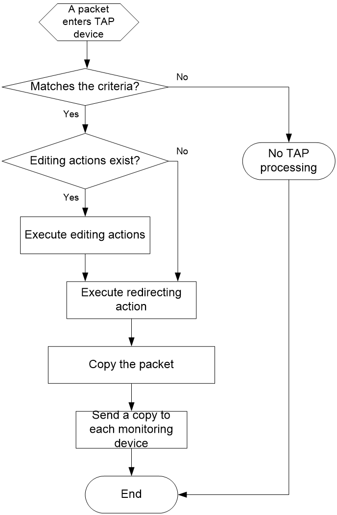
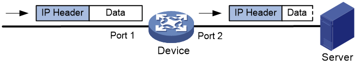
TAP workflow
Figure 1 shows the TAP workflow.
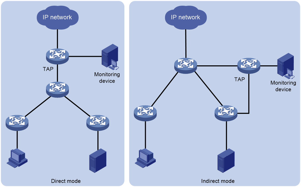
TAP deployment mode
A TAP device can be deployed in the following modes:
· Direct—The TAP device is deployed in the user network and can directly copy user traffic without affecting traffic forwarding and send copied traffic to monitoring devices. In this mode, packet editing actions cannot be configured.
· Indirect—The TAP device is deployed beside the user network. The user network device sends monitored traffic to the TAP device, which then sends the received traffic to monitoring devices. In this mode, packet editing actions can be configured as needed.
Figure 2 Deployment modes
Restrictions and guidelines: TAP configuration
In a TAP policy, you must configure the action of redirecting packets to a monitoring group, and you can configure packet editing actions as needed. If both the redirecting action and a packet editing action are configured, the packet editing action is executed before the redirecting action.
A TAP policy cannot take effect if the monitoring group in a redirecting action contains unsupported configurations. For such a TAP policy to take effect, perform the following tasks:
1. Delete the unsupported configurations in the monitoring group.
2. Delete the redirecting action and then reconfigure it, or remove the TAP policy and reapply it.
If you configure a packet header stripping action by executing the strip-header position command and specify an odd value for the offset-value argument, the deleted part is the odd value minus 1.
A TAP policy can be applied to only Layer 2 aggregate interfaces and Layer 3 aggregate interfaces.
A TAP policy is implemented through a QoS policy. For more information about related commands, see ACL and QoS Command Reference.
TAP tasks at a glance
To configure TAP, perform the following tasks:
2. Configuring a traffic class
3. Configuring a traffic behavior
¡ Configuring an M:N copying action
¡ Configuring a VLAN ID marking action
¡ Configuring an outer VLAN tag deleting action
¡ Configuring an outer VLAN tag adding action
¡ Configuring an IP or MAC address marking action
¡ Configuring a timestamp and Ethernet header adding action
¡ Configuring a packet truncation action
¡ Configuring a tunnel header stripping action
5. Applying a TAP policy to the inbound direction of an interface
Prerequisites for TAP configuration
Before configuring the redirecting action, configure a monitoring group (see flow monitoring configuration in Network Management and Monitoring Configuration Guide.
Enabling TAP globally
About this task
Perform this task if the device acts as a pure TAP device between a production network and a monitoring device. After TAP is enabled globally, the device disables unnecessary packet forwarding functions to prevent loops and broadcast storms.
Procedure
1. Enter system view.
system-view
2. Enable TAP globally.
tap enable
By default, TAP is disabled globally.
Configuring a traffic class
1. Enter system view.
system-view
2. Create a traffic class and enter traffic class view.
traffic classifier classifier-name [ operator { and | or } ]
3. Configure match criteria.
if-match match-criteria
By default, no match criterion is configured in a traffic class.
For more information, see ACL and QoS Command Reference.
Configuring a traffic behavior
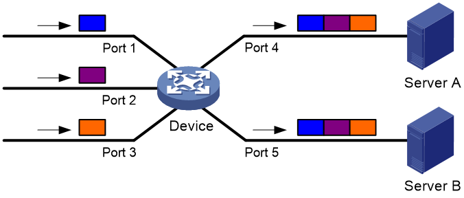
Configuring an M:N copying action
About this task
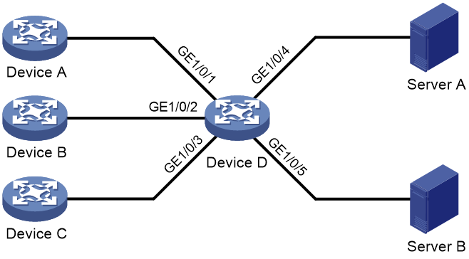
This feature allows the device to forward packets it receives from multiple (M) interfaces to multiple (N) data monitoring devices (Server A and Server B), as shown in Figure 3.
Restrictions and guidelines
You can implement this feature by performing the following steps:
1. Configure a monitoring group with N member interfaces.
2. Create M TAP policies, and configure an action of redirecting packets to the monitoring group with N member interfaces for each QoS policy.
3. Apply the M TAP policies to M interfaces.
Procedure
1. Enter system view.
system-view
2. Create a traffic behavior and enter traffic behavior view.
traffic behavior behavior-name
3. Configure an action of redirecting packets to a monitoring group.
redirect monitoring-group group-id
By default, no action of redirecting packets to a monitoring group is configured.
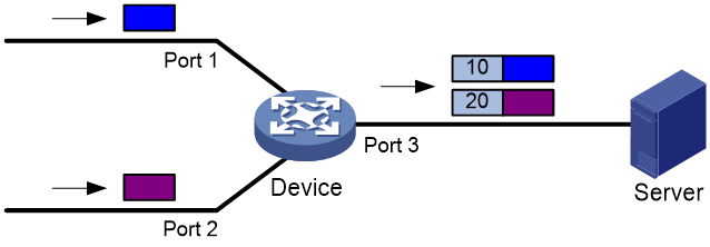
Configuring a VLAN ID marking action
About this task
This feature allows the device to mark packets received on different interfaces with different VLAN IDs. Then, the data monitoring device (the server) can identify the input interfaces of packets according to the marked VLAN IDs, as shown in Figure 4.
Procedure
1. Enter system view.
system-view
2. Create a traffic behavior and enter traffic behavior view.
traffic behavior behavior-name
3. Configure a VLAN ID marking action. Choose one option as needed:
¡ Configure a CVLAN ID marking action.
remark customer-vlan-id vlan-id
By default, no CVLAN ID marking action is configured.
¡ Configure an SVLAN ID marking action.
remark service-vlan-id vlan-id
By default, no SVLAN ID marking action is configured.
4. Configure an action of redirecting packets to a monitoring group.
redirect monitoring-group group-id
By default, no action of redirecting packets to a monitoring group is configured.
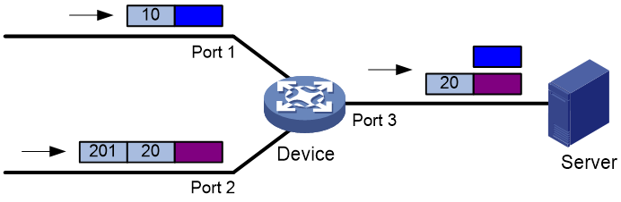
Configuring an outer VLAN tag deleting action
About this task
This feature is used in scenarios where the data monitoring device (the server) can only receive packets without VLAN tags or with one VLAN tag, as shown in Figure 5.
Procedure
1. Enter system view.
system-view
2. Create a traffic behavior and enter traffic behavior view.
traffic behavior behavior-name
3. Configure an outer VLAN tag deleting action.
strip-header top-most-vlan
By default, no outer VLAN tag deleting action is configured.
4. Configure an action of redirecting packets to a monitoring group.
redirect monitoring-group group-id
By default, no action of redirecting packets to a monitoring group is configured.
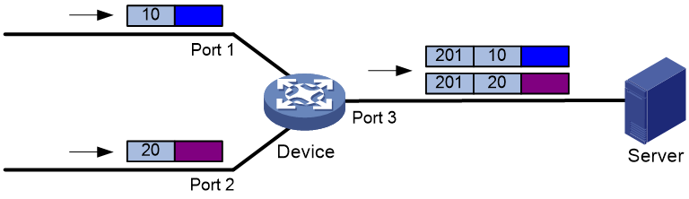
Configuring an outer VLAN tag adding action
About this task
In some scenarios, the device receives packets with different CVLAN IDs on different interfaces. However, the data monitoring device (the server) must receive packets with the same SVLAN ID, as shown in Figure 6. This feature is used in such scenarios.
Procedure
1. Enter system view.
system-view
2. Create a traffic behavior and enter traffic behavior view.
traffic behavior behavior-name
3. Configure an outer VLAN tag adding action.
nest top-most vlan vlan-id [ dot1p 802.1p ]
By default, no outer VLAN tag adding action is configured.
4. Configure an action of redirecting packets to a monitoring group.
redirect monitoring-group group-id
By default, no action of redirecting packets to a monitoring group is configured.
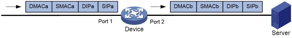
Configuring an IP or MAC address marking action
About this task
In some scenarios, the data monitoring device (the server) must receive packets with its own address as the destination address or identify the input interfaces of packets based on source addresses. This feature allows the device to modify the IP address and MAC address of packets, as shown in Figure 7.
Procedure
1. Enter system view.
system-view
2. Create a traffic behavior and enter traffic behavior view.
traffic behavior behavior-name
3. Configure an IP or MAC address marking action. Choose one option as needed:
¡ Configure a destination IPv4 address marking action.
remark destination-ip ipv4-address
By default, no destination IPv4 address marking action is configured.
¡ Configure a source IPv4 address marking action.
remark source-ip ipv4-address
By default, no source IPv4 address marking action is configured.
¡ Configure a destination IPv6 address marking action.
remark destination-ipv6 ipv6-address
By default, no destination IPv6 address marking action is configured.
¡ Configure a source IPv6 address marking action.
remark source-ipv6 ipv6-address
By default, no source IPv6 address marking action is configured.
¡ Configure a destination MAC address marking action.
remark destination-mac mac-address
By default, no destination MAC address marking action is configured.
¡ Configure a source MAC address marking action.
remark source-mac mac-address
By default, no source MAC address marking action is configured.
4. Configure an action of redirecting packets to a monitoring group.
redirect monitoring-group group-id
By default, no action of redirecting packets to a monitoring group is configured.
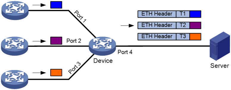
Configuring a timestamp and Ethernet header adding action
About this task
This feature allows a network to monitor the traffic of its internal devices.
Traditional TAP applications monitor the traffic on the egress device of a network. As the network grows and the performance requirements become higher, monitoring the traffic of the internal network devices is required. This feature is used in such scenarios.
As shown in Figure 8, interfaces on a TAP-enabled device connect to different devices. The device adds a timestamp, an Ethernet header, and a user-defined Ethernet protocol number to packets received on an interface, and redirects the packets to a monitoring group. Then, the device sends the packets to the data monitoring device (server). The server identifies the packets according to the Ethernet protocol number in the ETH Header field. The server calculates the network delay according to the timestamps TI, T2, and T3.
Procedure
1. Enter system view.
system-view
2. Create a traffic behavior and enter traffic behavior view.
traffic behavior behavior-name
3. Configure a timestamp and Ethernet header adding action.
timestamp-over-ether destination-mac mac-address source-mac mac-address ethtype-id ethtype-id
By default, no timestamp and Ethernet header adding action is configured.
4. Configure an action of redirecting packets to a monitoring group.
redirect monitoring-group group-id
By default, no action of redirecting packets to a monitoring group is configured.
Configuring a packet truncation action
About this task
This feature reduces the packet processing pressure on the data monitoring device (the server) or prevents the device from sending packet payloads to the server.
This feature truncates packets beginning from the Layer 2 header. The CRC is recalculated for the truncated part. The packet length after truncation is the truncated part plus the CRC length.
Figure 9 Network diagram
Procedure
1. Enter system view.
system-view
2. Create a traffic behavior and enter traffic behavior view.
traffic behavior behavior-name
3. Enable packet truncation.
truncation enable
By default, packet truncation is disabled.
4. Configure an action of redirecting packets to a monitoring group.
redirect monitoring-group group-id
By default, no action of redirecting packets to a monitoring group is configured.
5. Return to system view.
quit
6. Set the packet length after truncation.
qos truncation length length
The default setting is 128 bytes.
Configuring a tunnel header stripping action
About this task
In some scenarios, the data monitoring device (the server) cannot parse GRE, NVGRE, or VXLAN packets.
This feature allows the device to strip the tunnel header from the start of the outer Layer 2 header to the specified position.
Figure 10 GRE packet header stripping
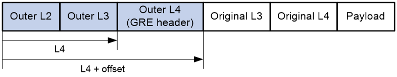
Figure 11 NVGRE packet header stripping
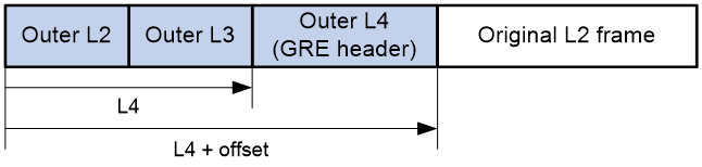
Figure 12 VXLAN packet header stripping
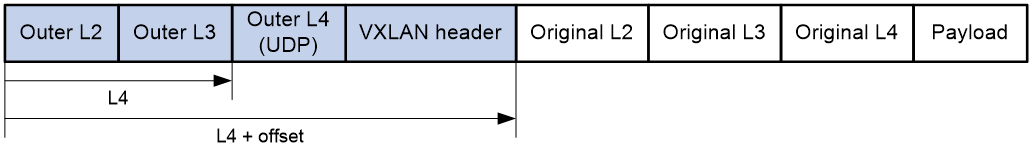
Figure 13 Network diagram for tunnel packet header stripping
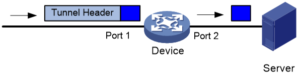
Procedure
1. Enter system view.
system-view
2. Create a traffic behavior and enter traffic behavior view.
traffic behavior behavior-name
3. Configure a tunnel header stripping action.
¡ Delete a tunnel header by using the user-defined method.
strip-header position { l2 | l3 | l4 } [ offset offset-value ]
¡ Delete the GRE header.
strip-header gre header-length header-length encap-eth-header destination-mac mac-address source-mac mac-address [ vlan vlan-id [ dot1p dot1p-value ] ] ethtype-id ethtype-id
¡ Delete the NVGRE header.
strip-header nvgre
¡ Delete the VXLAN header.
strip-header vxlan
By default, no tunnel header stripping action is configured.
4. Configure an action of redirecting packets to a monitoring group.
redirect monitoring-group group-id
By default, no action of redirecting packets to a monitoring group is configured.
Configuring a TAP policy
1. Enter system view.
system-view
2. Create a TAP policy and enter TAP policy view.
qos tap policy policy-name
3. Associate a traffic class with a traffic behavior in the TAP policy.
classifier classifier-name behavior behavior-name
By default, no traffic behavior is associated with a traffic class.
Applying a TAP policy to the inbound direction of an interface
1. Enter system view.
system-view
2. Enter interface view.
interface interface-type interface-number
3. Apply a TAP policy to the interface.
qos apply tap policy policy-name inbound [ inner-match ]
By default, no TAP policy is applied to an interface.
Display and maintenance commands for TAP
Execute display commands in any view.
|
Task |
Command |
|
Display traffic class configuration. |
display traffic classifier user-defined [ classifier-name ] [ slot slot-number ] For more information about this command, see flow mirroring commands in ACL and QoS Command Reference. |
|
Display traffic behavior configuration. |
display traffic behavior user-defined [ behavior-name ] [ slot slot-number ] For more information about this command, see flow mirroring commands in ACL and QoS Command Reference. |
|
Display monitoring group information. |
display monitoring-group { group-id | all } For more information about this command, see flow mirroring commands in Network Management and Monitoring Command Reference. |
|
Display TAP policy configuration. |
display qos policy user-defined tap [ policy-name [ classifier classifier-name ] ] [ slot slot-number ] |
|
Display the configuration and statistics of TAP policies applied to interfaces. |
display qos tap policy interface [ interface-type interface-number [ inbound ] [ slot slot-number ] |
TAP configuration examples
Example: Configuring basic M:N copying
Network configuration
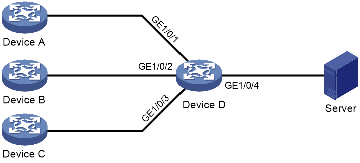
As shown in Figure 14, Device D is a TAP device. Configure M:N copying on Device D to forward all packets received on GigabitEthernet 1/0/1, GigabitEthernet 1/0/2, and GigabitEthernet 1/0/3 to Server A and Server B through GigabitEthernet 1/0/4 and GigabitEthernet 1/0/5.
Procedure
1. Enable TAP globally.
<DeviceD> system-view
[DeviceD] tap enable
2. Create monitoring group 1, and assign GigabitEthernet 1/0/4 and GigabitEthernet 1/0/5 to the monitoring group.
[DeviceD] monitoring-group 1
[DeviceD-monitoring-group-1] monitoring-port gigabitethernet 1/0/4 to gigabitethernet 1/0/5
[DeviceD-monitoring-group-1] quit
3. Create a traffic class named classifier_tap, and configure the traffic class to match all packets.
[DeviceD] traffic classifier classifier_tap
[DeviceD-classifier-classifier_tap] if-match any
[DeviceD-classifier-classifier_tap] quit
4. Create a traffic behavior named behavior_tap, and configure an action of redirecting packets to monitoring group 1.
[DeviceD] traffic behavior behavior_tap
[DeviceD-behavior-behavior_tap] redirect monitoring-group 1
[DeviceD-behavior-behavior_tap] quit
5. Create a TAP policy named policy_tap, and associate the traffic class with the traffic behavior in the TAP policy.
[DeviceD] qos tap policy policy_tap
[DeviceD-qospolicy-policy_tap] classifier classifier_tap behavior behavior_tap
[DeviceD-qospolicy-policy_tap] quit
6. Applying the TAP policy.
# Applying the TAP policy to the inbound direction of GigabitEthernet 1/0/1.
[DeviceD] interface gigabitethernet 1/0/1
[DeviceD-GigabitEthernet1/0/1] qos apply tap policy policy_tap inbound
[DeviceD-GigabitEthernet1/0/1] quit
# Applying the TAP policy to the inbound direction of GigabitEthernet 1/0/2.
[DeviceD] interface gigabitethernet 1/0/2
[DeviceD-GigabitEthernet1/0/2] qos apply tap policy policy_tap inbound
[DeviceD-GigabitEthernet1/0/2] quit
# Applying the TAP policy to the inbound direction of GigabitEthernet 1/0/3.
[DeviceD] interface gigabitethernet 1/0/3
[DeviceD-GigabitEthernet1/0/3] qos apply tap policy policy_tap inbound
[DeviceD-GigabitEthernet1/0/3] quit
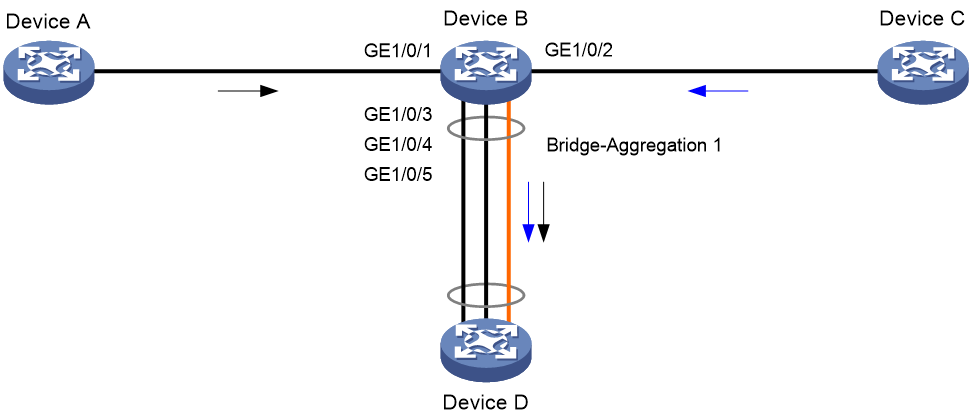
Example: Configuring M:N copying for aggregate interfaces
Network configuration
As shown in Figure 15, Device B is a TAP device. Packets from Device A to Device C enter Device B on GigabitEthernet 1/0/1 and are sent to Device C on GigabitEthernet 1/0/2. Packets from Device C to Device A enter Device B on GigabitEthernet 1/0/2 and are sent to Device A on GigabitEthernet 1/0/1.
Configure M:N copying and link aggregation load sharing on Device B to meet the following requirements:
· Incoming packets on GigabitEthernet 1/0/1 and GigabitEthernet 1/0/2 are redirected to the aggregate interface.
· The aggregate interface loads share packets based on source IP addresses and destination IP addresses.
· The aggregate interface sends incoming packets on GigabitEthernet 1/0/1 and GigabitEthernet 1/0/2 to Device D over the same link by using algorithm 1 as the link aggregation load sharing algorithm.
Procedure
1. Enable TAP globally.
<DeviceB> system-view
[DeviceB] tap enable
2. Configure an aggregate interface:
# Create a Layer 2 aggregate interface named Bridge-Aggregation 1.
[DeviceB] interface bridge-aggregation 1
[DeviceB-Bridge-Aggregation1] quit
# Assign GigabitEthernet 1/0/3, GigabitEthernet 1/0/4, and GigabitEthernet 1/0/5 to the aggregation group.
[DeviceB] interface gigabitethernet 1/0/3
[DeviceB-GigabitEthernet1/0/3] port link-aggregation group 1
[DeviceB-GigabitEthernet1/0/3] quit
[DeviceB] interface gigabitethernet 1/0/4
[DeviceB-GigabitEthernet1/0/4] port link-aggregation group 1
[DeviceB-GigabitEthernet1/0/4] quit
[DeviceB] interface gigabitethernet 1/0/5
[DeviceB-GigabitEthernet1/0/5] port link-aggregation group 1
[DeviceB-GigabitEthernet1/0/5] quit
|
|
NOTE: You can use the port link-mode command to configure an Ethernet port as a Layer 2 or Layer 3 interface (see Layer 2—LAN Switching Configuration Guide). |
3. Configure a monitoring group:
# Create monitoring group 1, and assign the Layer 2 aggregate interface to the monitoring group.
[DeviceB] monitoring-group 1
[DeviceB-monitoring-group-1] monitoring-port bridge-aggregation 1
[DeviceB-monitoring-group-1] quit
4. Configure traffic classes:
# Create IPv4 advanced ACL 3001, and configure a rule to match packets with source IP address 192.168.1.1 and destination IP address 192.168.2.1.
[DeviceB] acl advanced 3001
[DeviceB-acl-ipv4-adv-3001] rule permit ip source 192.168.1.1 0 destination 192.168.2.1 0
[DeviceB-acl-ipv4-adv-3001] quit
# Create a traffic class named classifier1, and use ACL 3001 as the match criterion.
[DeviceB] traffic classifier classifier1
[DeviceB-classifier-classifier1] if-match acl 3001
[DeviceB-classifier-classifier1] quit
# Create IPv4 advanced ACL 3002, and configure a rule to match packets with source IP address 192.168.2.1 and destination IP address 192.168.1.1.
[DeviceB] acl advanced 3002
[DeviceB-acl-ipv4-adv-3002] rule permit ip source 192.168.2.1 0 destination 192.168.1.1 0
[DeviceB-acl-ipv4-adv-3002] quit
# Create a traffic class named classifier2, and use ACL 3002 as the match criterion.
[DeviceB] traffic classifier classifier2
[DeviceB-classifier-classifier2] if-match acl 3002
[DeviceB-classifier-classifier2] quit
5. Configure a traffic behavior:
# Create a traffic behavior named behavior1, and configure an action of redirecting packets to monitoring group 1.
[DeviceD] traffic behavior behavior_tap
[DeviceD-behavior-behavior_tap] redirect monitoring-group 1
[DeviceD-behavior-behavior_tap] quit
6. Configure TAP policies:
# Create a TAP policy named policy1, and associate traffic class classifier1 with traffic behavior behavior1 in the TAP policy.
[DeviceB] qos tap policy policy1
[DeviceB-qospolicy-policy1] classifier classifier1 behavior behavior1
[DeviceB-qospolicy-policy1] quit
# Create a TAP policy named policy2, and associate traffic class classifier2 with traffic behavior behavior1 in the TAP policy.
[DeviceB] qos tap policy policy2
[DeviceB-qospolicy-policy2] classifier classifier2 behavior behavior1
[DeviceB-qospolicy-policy2] quit
7. Applying TAP policies:
# Applying TAP policy policy1 to the inbound direction of GigabitEthernet 1/0/1.
[DeviceD] interface gigabitethernet 1/0/1
[DeviceD-GigabitEthernet1/0/1] qos apply tap policy policy1 inbound
[DeviceD-GigabitEthernet1/0/1] quit
# Applying TAP policy policy2 to the inbound direction of GigabitEthernet 1/0/2.
[DeviceD] interface gigabitethernet 1/0/2
[DeviceD-GigabitEthernet1/0/2] qos apply tap policy policy2 inbound
[DeviceD-GigabitEthernet1/0/2] quit
8. Set the global load sharing mode to load share packets based on source IP addresses and destination IP addresses.
[DeviceB] link-aggregation global load-sharing mode source-ip destination-ip
9. Specify algorithm 1 as the link aggregation load sharing algorithm.
[DeviceB] link-aggregation global load-sharing algorithm 1
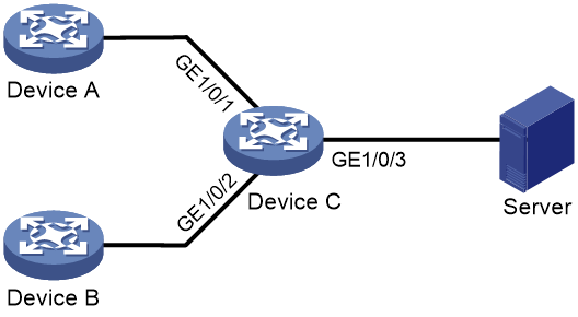
Example: Configuring VLAN ID marking
Network configuration
As shown in Figure 16, Device C is a TAP device. Configure VLAN ID marking on Device C to meet the following requirements:
· Mark CVLAN 10 for packets received on GigabitEthernet 1/0/1.
· Mark CVLAN 20 for packets received on GigabitEthernet 1/0/2.
· Forward packets with CVLAN 10 and packets with CVLAN 20 to the server through GigabitEthernet 1/0/3, enabling the server to identify the input interfaces of packets according to VLAN IDs.

Procedure
1. Enable TAP globally.
<DeviceC> system-view
[DeviceC] tap enable
2. Create monitoring group 1, and assign GigabitEthernet 1/0/3 to the monitoring group.
[DeviceC] monitoring-group 1
[DeviceC-monitoring-group-1] monitoring-port gigabitethernet 1/0/3
[DeviceC-monitoring-group-1] quit
3. Create a traffic class named classifier_tap, and configure the traffic class to match all packets.
[DeviceC] traffic classifier classifier_tap
[DeviceC-classifier-classifier_tap] if-match any
[DeviceC-classifier-classifier_tap] quit
4. Configure traffic behaviors:
# Create a traffic behavior named behavior_tap1, and configure an action of marking CVLAN 10 and an action of redirecting packets to monitoring group 1.
[DeviceC] traffic behavior behavior_tap1
[DeviceC-behavior-behavior_tap1] remark customer-vlan-id 10
[DeviceC-behavior-behavior_tap1] redirect monitoring-group 1
[DeviceC-behavior-behavior_tap1] quit
# Create a traffic behavior named behavior_tap2, and configure an action of marking CVLAN 20 and an action of redirecting packets to monitoring group 1.
[DeviceC] traffic behavior behavior_tap2
[DeviceC-behavior-behavior_tap2] remark customer-vlan-id 20
[DeviceC-behavior-behavior_tap2] redirect monitoring-group 1
[DeviceC-behavior-behavior_tap2] quit
5. Configure TAP policies:
# Create a TAP policy named policy_tap1, and associate traffic class classifier_tap with traffic behavior behavior_tap1 in the TAP policy.
[DeviceC] qos tap policy policy_tap1
[DeviceC-qospolicy-policy_tap1] classifier classifier_tap behavior behavior_tap1
[DeviceC-qospolicy-policy_tap1] quit
# Create a TAP policy named policy_tap2, and associate traffic class classifier_tap with traffic behavior behavior_tap2 in the TAP policy.
[DeviceC] qos tap policy policy_tap2
[DeviceC-qospolicy-policy_tap2] classifier classifier_tap behavior behavior_tap2
[DeviceC-qospolicy-policy_tap2] quit
6. Apply the TAP policies.
# Apply TAP policy policy_tap1 to the inbound direction of GigabitEthernet 1/0/1.
[DeviceC] interface gigabitethernet 1/0/1
[DeviceC-GigabitEthernet1/0/1] qos apply tap policy policy_tap1 inbound
[DeviceC-GigabitEthernet1/0/1] quit
# Apply TAP policy policy_tap2 to the inbound direction of GigabitEthernet 1/0/2.
[DeviceC] interface gigabitethernet 1/0/2
[DeviceC-GigabitEthernet1/0/2] qos apply tap policy policy_tap2 inbound
[DeviceC-GigabitEthernet1/0/2] quit
Example: Configuring outer VLAN tag deleting
Network configuration
As shown in Figure 17, Device C is a TAP device, and GigabitEthernet 1/0/1 and GigabitEthernet 1/0/2 receive double-tagged packets.
Configure Device C to meet the following requirements:
· Delete the outer VLAN tag of the packets received on GigabitEthernet 1/0/1 and GigabitEthernet 1/0/2.
· Forward the packets to the server through GigabitEthernet 1/0/3.
Procedure
1. Enable TAP globally.
<DeviceC> system-view
[DeviceC] tap enable
2. Create monitoring group 1, and assign GigabitEthernet 1/0/3 to the monitoring group.
[DeviceC] monitoring-group 1
[DeviceC-monitoring-group-1] monitoring-port gigabitethernet 1/0/3
[DeviceC-monitoring-group-1] quit
3. Create a traffic class named classifier_tap, and configure the traffic class to match all packets.
[DeviceC] traffic classifier classifier_tap
[DeviceC-classifier-classifier_tap] if-match any
[DeviceC-classifier-classifier_tap] quit
4. Create a traffic behavior named behavior_tap, and configure an outer VLAN tag deleting action and an action of redirecting packets to monitoring group 1.
[DeviceC] traffic behavior behavior_tap
[DeviceC-behavior-behavior_tap] strip-header top-most-vlan
[DeviceC-behavior-behavior_tap] redirect monitoring-group 1
[DeviceC-behavior-behavior_tap] quit
5. Create a TAP policy named policy_tap, and associate the traffic class with the traffic behavior in the TAP policy.
[DeviceC] qos tap policy policy_tap
[DeviceC-qospolicy-policy_tap] classifier classifier_tap behavior behavior_tap
[DeviceC-qospolicy-policy_tap] quit
6. Apply the TAP policy.
# Apply TAP policy policy_tap to the inbound direction of GigabitEthernet 1/0/1.
[DeviceC] interface gigabitethernet 1/0/1
[DeviceC-GigabitEthernet1/0/1] qos apply tap policy policy_tap inbound
[DeviceC-GigabitEthernet1/0/1] quit
# Apply TAP policy policy_tap to the inbound direction of GigabitEthernet 1/0/2.
[DeviceC] interface gigabitethernet 1/0/2
[DeviceC-GigabitEthernet1/0/2] qos apply tap policy policy_tap inbound
[DeviceC-GigabitEthernet1/0/2] quit
Example: Configuring outer VLAN tag adding
Network configuration
As shown in Figure 18, Device C is a TAP device, and GigabitEthernet 1/0/1 and GigabitEthernet 1/0/2 receive single-tagged packets.
Configure Device C to meet the following requirements:
· Add an outer VLAN tag for the packets received on GigabitEthernet 1/0/1 and GigabitEthernet 1/0/2.
· Forward the packets to the server through GigabitEthernet 1/0/3.

Procedure
1. Enable TAP globally.
<DeviceC> system-view
[DeviceC] tap enable
2. Create monitoring group 1, and assign GigabitEthernet 1/0/3 to the monitoring group.
[DeviceC] monitoring-group 1
[DeviceC-monitoring-group-1] monitoring-port gigabitethernet 1/0/3
[DeviceC-monitoring-group-1] quit
3. Create a traffic class named classifier_tap, and configure the traffic class to match all packets.
[DeviceC] traffic classifier classifier_tap
[DeviceC-classifier-classifier_tap] if-match any
[DeviceC-classifier-classifier_tap] quit
4. Create a traffic behavior named behavior_tap, and configure an outer VLAN tag adding action and an action of redirecting packets to monitoring group 1.
[DeviceC] traffic behavior behavior_tap
[DeviceC-behavior-behavior_tap] nest top-most vlan 10
[DeviceC-behavior-behavior_tap] redirect monitoring-group 1
[DeviceC-behavior-behavior_tap] quit
5. Create a TAP policy named policy_tap, and associate the traffic class with the traffic behavior in the TAP policy.
[DeviceC] qos tap policy policy_tap
[DeviceC-qospolicy-policy_tap] classifier classifier_tap behavior behavior_tap
[DeviceC-qospolicy-policy_tap] quit
6. Apply the TAP policy.
# Apply TAP policy policy_tap to the inbound direction of GigabitEthernet 1/0/1.
[DeviceC] interface gigabitethernet 1/0/1
[DeviceC-GigabitEthernet1/0/1] qos apply tap policy policy_tap inbound
[DeviceC-GigabitEthernet1/0/1] quit
# Apply TAP policy policy_tap to the inbound direction of GigabitEthernet 1/0/2.
[DeviceC] interface gigabitethernet 1/0/2
[DeviceC-GigabitEthernet1/0/2] qos apply tap policy policy_tap inbound
[DeviceC-GigabitEthernet1/0/2] quit
Example: Configuring destination MAC address marking
Network configuration
As shown in Figure 19, Device B is a TAP device. Configure Device B to meet the following requirements:
· Modify the destination MAC address of the packets received on GigabitEthernet 1/0/1 as the MAC address of the server.
· Forward the packets to the server through GigabitEthernet 1/0/2.

Procedure
1. Enable TAP globally.
<DeviceB> system-view
[DeviceB] tap enable
2. Create monitoring group 1, and assign GigabitEthernet 1/0/2 to the monitoring group.
[DeviceB] monitoring-group 1
[DeviceB-monitoring-group-1] monitoring-port gigabitethernet 1/0/2
[DeviceB-monitoring-group-1] quit
3. Create a traffic class named classifier_tap, and configure the traffic class to match all packets.
[DeviceB] traffic classifier classifier_tap
[DeviceB-classifier-classifier_tap] if-match any
[DeviceB-classifier-classifier_tap] quit
4. Create a traffic behavior named behavior_tap, and configure a destination MAC address marking action and an action of redirecting packets to monitoring group 1.
[DeviceB] traffic behavior behavior_tap
[DeviceB-behavior-behavior_tap] remark destination-mac 0050-ba27-bed3
[DeviceB-behavior-behavior_tap] redirect monitoring-group 1
[DeviceB-behavior-behavior_tap] quit
5. Create a TAP policy named policy_tap, and associate the traffic class with the traffic behavior in the TAP policy.
[DeviceB] qos tap policy policy_tap
[DeviceB-qospolicy-policy_tap] classifier classifier_tap behavior behavior_tap
[DeviceB-qospolicy-policy_tap] quit
6. Apply TAP policy policy_tap to the inbound direction of GigabitEthernet 1/0/1.
[DeviceB] interface gigabitethernet 1/0/1
[DeviceB-GigabitEthernet1/0/1] qos apply tap policy policy_tap inbound
[DeviceB-GigabitEthernet1/0/1] quit
Example: Configuring timestamp and Ethernet header adding
Network configuration
As shown in Figure 20, Device D is a TAP device. Configure timestamp and Ethernet header adding on Device D to meet the following requirements:
· Add destination MAC address 0050-ba27-bed4, source MAC address 0050-ba27-bed1, and Ethernet protocol number FF for packets received on GigabitEthernet 1/0/1.
· Add destination MAC address 0050-ba27-bed4, source MAC address 0050-ba27-bed2, and Ethernet protocol number FF for packets received on GigabitEthernet 1/0/2.
· Add destination MAC address 0050-ba27-bed4, source MAC address 0050-ba27-bed3, and Ethernet protocol number FF for packets received on GigabitEthernet 1/0/3.
· Forward the packets to the server through GigabitEthernet 1/0/4.
Procedure
1. Enable TAP globally.
<DeviceD> system-view
[DeviceD] tap enable
2. Create monitoring group 1, and assign GigabitEthernet 1/0/4 to the monitoring group.
[DeviceD] monitoring-group 1
[DeviceD-monitoring-group-1] monitoring-port gigabitethernet 1/0/4
[DeviceD-monitoring-group-1] quit
3. Configure a traffic class.
# Create IPv4 advanced ACL 3001, and configure a rule to match all TCP packets.
[DeviceD] acl advanced 3001
[DeviceD-acl-ipv4-adv-3001] rule permit tcp
[DeviceD-acl-ipv4-adv-3001] quit
# Create a traffic class named classifier_tap, and use ACL 3001 as the match criterion.
[DeviceD] traffic classifier classifier_tap
[DeviceD-classifier-classifier_tap] if-match acl 3001
[DeviceD-classifier-classifier_tap] quit
4. Configure traffic behaviors:
# Create a traffic behavior named behavior_tap1, and configure an action of add destination MAC address 0050-ba27-bed4, source MAC address 0050-ba27-bed1, and Ethernet protocol number FF, and an action of redirecting packets to monitoring group 1.
[DeviceD] traffic behavior behavior_tap1
[DeviceD-behavior-behavior_tap1] timestamp-over-ether destination-mac 0050-ba27-bed4 source-mac 0050-ba27-bed1 ethtype-id ff
[DeviceD-behavior-behavior_tap1] redirect monitoring-group 1
[DeviceD-behavior-behavior_tap1] quit
# Create a traffic behavior named behavior_tap2, and configure an action of adding destination MAC address 0050-ba27-bed4, source MAC address 0050-ba27-bed2, and Ethernet protocol number FF, and an action of redirecting packets to monitoring group 1.
[DeviceD] traffic behavior behavior_tap2
[DeviceD-behavior-behavior_tap2] timestamp-over-ether destination-mac 0050-ba27-bed4 source-mac 0050-ba27-bed2 ethtype-id ff
[DeviceD-behavior-behavior_tap2] redirect monitoring-group 1
[DeviceD-behavior-behavior_tap2] quit
# Create a traffic behavior named behavior_tap3, and configure an action of adding destination MAC address 0050-ba27-bed4, source MAC address 0050-ba27-bed3, and Ethernet protocol number FF, and an action of redirecting packets to monitoring group 1.
[DeviceD] traffic behavior behavior_tap3
[DeviceD-behavior-behavior_tap3] timestamp-over-ether destination-mac 0050-ba27-bed4 source-mac 0050-ba27-bed3 ethtype-id ff
[DeviceD-behavior-behavior_tap3] redirect monitoring-group 1
[DeviceD-behavior-behavior_tap2] quit
5. Configure TAP policies:
# Create a TAP policy named policy_tap1, and associate traffic class classifier_tap with traffic behavior behavior_tap1 in the TAP policy.
[DeviceD] qos tap policy policy_tap1
[DeviceD-qospolicy-policy_tap1] classifier classifier_tap behavior behavior_tap1
[DeviceD-qospolicy-policy_tap1] quit
# Create a TAP policy named policy_tap2, and associate traffic class classifier_tap with traffic behavior behavior_tap2 in the TAP policy.
[DeviceD] qos tap policy policy_tap2
[DeviceD-qospolicy-policy_tap2] classifier classifier_tap behavior behavior_tap2
[DeviceD-qospolicy-policy_tap2] quit
# Create a TAP policy named policy_tap3, and associate traffic class classifier_tap with traffic behavior behavior_tap3 in the TAP policy.
[DeviceD] qos tap policy policy_tap3
[DeviceD-qospolicy-policy_tap3] classifier classifier_tap behavior behavior_tap3
[DeviceD-qospolicy-policy_tap3] quit
6. Apply the TAP policies:
# Apply TAP policy policy_tap1 to the inbound direction of GigabitEthernet 1/0/1.
[DeviceD] interface gigabitethernet 1/0/1
[DeviceD-GigabitEthernet1/0/1] qos apply tap policy policy_tap1 inbound
[DeviceD-GigabitEthernet1/0/1] quit
# Apply TAP policy policy_tap2 to the inbound direction of GigabitEthernet 1/0/2.
[DeviceD] interface gigabitethernet 1/0/2
[DeviceD-GigabitEthernet1/0/2] qos apply tap policy policy_tap2 inbound
[DeviceD-GigabitEthernet1/0/2] quit
# Apply TAP policy policy_tap3 to the inbound direction of GigabitEthernet 1/0/3.
[DeviceD] interface gigabitethernet 1/0/3
[DeviceD-GigabitEthernet1/0/3] qos apply tap policy policy_tap2 inbound
[DeviceD-GigabitEthernet1/0/3] quit
Example: Configuring packet truncation
Network configuration
As shown in Figure 21, Device B is a TAP device. Configure Device B to meet the following requirements:
· Truncate the packets received on GigabitEthernet 1/0/1.
· Forward the truncated packets to the server through GigabitEthernet 1/0/2.

Procedure
1. Enable TAP globally.
<DeviceB> system-view
[DeviceB] tap enable
2. Create monitoring group 1, and assign GigabitEthernet 1/0/2 to the monitoring group.
[DeviceB] monitoring-group 1
[DeviceB-monitoring-group-1] monitoring-port gigabitethernet 1/0/2
[DeviceB-monitoring-group-1] quit
3. Configure a traffic class.
# Create IPv4 advanced ACL 3001, and configure a rule to match TCP packets with source IP address 10.0.0.1 and mask 255.255.255.0.
[DeviceB] acl advanced 3001
[DeviceB-acl-ipv4-adv-3001] rule permit tcp source 10.0.0.1 255.255.255.0
[DeviceB-acl-ipv4-adv-3001] quit
# Create a traffic class named classifier_tap, and use ACL 3001 as the match criterion.
[DeviceB] traffic classifier classifier_tap
[DeviceB-classifier-classifier_tap] if-match acl 3001
[DeviceB-classifier-classifier_tap] quit
4. Create a traffic behavior named behavior_tap, and configure a packet truncation enabling action and an action of redirecting packets to monitoring group 1.
[DeviceB] traffic behavior behavior_tap
[DeviceB-behavior-behavior_tap] truncation enable
[DeviceB-behavior-behavior_tap] redirect monitoring-group 1
[DeviceB-behavior-behavior_tap] quit
5. Configure packet truncation.
# Set the packet truncation length to 100 bytes.
[DeviceB] qos truncation length 100
6. Create a TAP policy named policy_tap, and associate the traffic class with the traffic behavior in the TAP policy.
[DeviceB] qos tap policy policy_tap
[DeviceB-qospolicy-policy_tap] classifier classifier_tap behavior behavior_tap
[DeviceB-qospolicy-policy_tap] quit
7. Apply TAP policy policy_tap to the inbound direction of GigabitEthernet 1/0/1.
[DeviceB] interface gigabitethernet 1/0/1
[DeviceB-GigabitEthernet1/0/1] qos apply tap policy policy_tap inbound
[DeviceB-GigabitEthernet1/0/1] quit
Example: Configuring NVGRE header stripping
Network configuration
As shown in Figure 22, Device B is a TAP device, and the server does not support parsing NVGRE packets.
Configure NVGRE header stripping on GigabitEthernet 1/0/1 and traffic redirecting to GigabitEthernet 1/0/2.

Procedure
1. Enable TAP globally.
<DeviceB> system-view
[DeviceB] tap enable
2. Create monitoring group 1, and assign GigabitEthernet 1/0/2 to the monitoring group.
[DeviceB] monitoring-group 1
[DeviceB-monitoring-group-1] monitoring-port gigabitethernet 1/0/2
[DeviceB-monitoring-group-1] quit
3. Create a traffic class named classifier_tap, and configure the traffic class to match NVGRE packets with VSID FFFF28.
[DeviceB] traffic classifier classifier_tap
[DeviceB-classifier-classifier_tap] if-match nvgre-vsid ffff28
[DeviceB-classifier-classifier_tap] quit
4. Create a traffic behavior named behavior_tap, and configure an action of stripping the outer Layer 2 header, outer Layer 3 header, and the GRE header of NVGRE packets, and an action of redirecting packets to monitoring group 1.
[DeviceB] traffic behavior behavior_tap
[DeviceB-behavior-behavior_tap] strip-header position l4 offset 4
[DeviceB-behavior-behavior_tap] redirect monitoring-group 1
[DeviceB-behavior-behavior_tap] quit
5. Create a TAP policy named policy_tap, and associate the traffic class with the traffic behavior in the TAP policy.
[DeviceB] qos tap policy policy_tap
[DeviceB-qospolicy-policy_tap] classifier classifier_tap behavior behavior_tap
[DeviceB-qospolicy-policy_tap] quit
6. Apply TAP policy policy_tap to the inbound direction of GigabitEthernet 1/0/1.
<DeviceB> system-view
[DeviceB] interface gigabitethernet 1/0/1
[DeviceB-GigabitEthernet1/0/1] qos apply tap policy policy_tap inbound
[DeviceB-GigabitEthernet1/0/1] quit
