- Table of Contents
- Related Documents
-
| Title | Size | Download |
|---|---|---|
| 01-Text | 3.36 MB |
Contents
Verifying the software package
Deployment procedure at a glance
Registering and installing licenses
Installing the activation file on the license server
Backing up and restoring the controller configuration
Upgrading the controller and DTN
Uninstalling SeerEngine-DC and DTN
Uninstalling the DTN component only
Scaling out or in the controller
Scaling out the controller from standalone mode to cluster mode
Scaling out the controller in cluster mode
Scaling in the controller in cluster mode
RDRS deployment procedure at a glance
Deploying the primary and backup sites
Configuring the RDRS settings for the controllers at the primary and backup sites
Deploying the third-party arbitration service
Deploying the third-party arbitration service
Uninstalling the third-party arbitration service
Upgrading the third-party arbitration service
Upgrading the controller to support RDRS
Changing the license owner at an RDRS switchover
Cluster deployment over a Layer 3 network
Deploying the controller at Layer 3
About cluster 2+1+1 deployment
About the controller
SeerEngine-DC is a data center controller. Similar to a network operating system, the controller drives SDN application development and allows operation of various SDN applications. It can control various resources on the network and provide interfaces for applications to enable specific network forwarding.
The controller has the following features:
· It supports OpenFlow 1.3 and provides built-in services and a device driver framework.
· It is a distributed platform with high availability and scalability.
· It provides extensible REST APIs and GUI.
· It can operate in standalone or cluster mode.
Preparing for installation
Server requirements
Hardware requirements
The controller can be deployed on a single server or on a cluster of servers. As a best practice, deploy the controller on a cluster of three servers.
The controller supports RDRS, which provides disaster recovery services between the primary and backup sites. In the 3+3 RDRS mode, the primary and backup sites each require three servers.
The controller supports deploying the simulation feature. To use the simulation feature, you need to deploy the DTN component and DTN physical host, and simulate the real network environment 1:1 through virtual switches.
For more information about the hardware requirements in various deployment scenarios of the controller, see the AD-Net solution hardware configuration guide.
Software requirements
SeerEngine-DC runs on Unified Platform as a component. Before deploying SeerEngine-DC, first install Unified Platform. Table 1 describes the CPU and operating system compatibility.
Table 1 CPU and operating system compatibility
|
CPU |
Supported operating systems |
Recommended operating system |
|
x86-64 (Intel64/AMD64) |
· H3Linux 1.1.2 · H3Linux 2.0 (Unified Platform E0711 and later) · Kylin V10 SP2 |
H3Linux 1.1.2 |
|
x86-64 Hygon |
· H3Linux 2.0 (Unified Platform E0711 and later) · Kylin V10 SP2 |
Kylin V10 SP2 |
|
ARM Kunpeng |
· H3Linux 2.0 (Unified Platform E0711 and later) · Kylin V10 SP2 |
Kylin V10 SP2 |
|
ARM Phytium |
Kylin V10 SP2 |
Kylin V10 SP2 |
Client requirements
You can access Unified Platform from a Web browser without installing any client. As a best practice, use Google Chrome 70 or a later version.
Pre-installation checklist
Table 2 Pre-installation checklist
|
Item |
Requirements |
|
|
Server |
Hardware |
· The CPUs, memory, drives, and network interfaces meet the requirements. · The server supports Unified Platform. |
|
Software |
The system time settings are configured correctly. As a best practice, configure NTP for time synchronization and make sure the devices synchronize to the same clock source. |
|
|
Client |
You can access Unified Platform from a Web browser without installing any client. As a best practice, use Google Chrome 70 or a later version. |
|
Verifying the software package
Before installing the software, verify the MD5 checksum of the software package for integrity and correctness.
Deployment procedure at a glance
Use the following procedure to deploy the controller:
1. Prepare for installation.
Prepare a minimum of three physical servers. Make sure the physical servers meet the hardware and software requirements as described in "Server requirements."
2. Deploy Unified Platform.
For the deployment procedure, see H3C Unified Platform Deployment Guide.
3. Deploy SeerEngine-DC components.
4. Deploy the DTN component.
For the deployment procedure, see H3C SeerEngine-DC Simulation Network Deployment Guide.
5. Deploy simulated services.
For the deployment procedure, see H3C SeerEngine-DC Simulation Network Environment Deployment Guide.
Installing Unified Platform
SeerEngine-DC runs on Unified Platform as a component. Before deploying SeerEngine-DC, first install Unified Platform. For the detailed procedure, see H3C Unified Platform Deployment Guide.
To run SeerEngine-DC on Unified Platform, you are required to partition the drive and deploy the application packages required by SeerEngine-DC.
Partitioning the system drive
Before installing Unified Platform, partition the system drive as described in Table 3. Do not use the automatic partitioning feature.
Table 3 Drive partition settings (2400 GB partition)
|
RAID configuration |
Partition |
Mount point |
Min. capacity |
Remarks |
|
2400 GB or higher after RAID 10 setup |
/dev/sda1 |
/boot/efi |
200 MiB |
EFI System Partition type. This partition is required only in UEFI mode. |
|
/dev/sda2 |
/boot |
1024 MiB |
N/A |
|
|
/dev/sda3 |
/ |
900 GiB |
Expandable when the drive space is sufficient. |
|
|
/dev/sda4 |
/var/lib/docker |
460 GiB |
Expandable when the drive space is sufficient. |
|
|
/dev/sda6 |
swap |
1024 MiB |
Swap type. |
|
|
/dev/sda7 |
/var/lib/ssdata |
520 GiB |
Expandable when the drive space is sufficient. |
|
|
/dev/sda8 |
N/A |
300 GiB |
Reserved for GlusterFS. Not required when the operating system is installed. |
|
|
50 GB or higher after RAID 1 setup |
/dev/sdb |
/var/lib/etcd |
50 GiB |
· For the controller in a version earlier than E6203 and Unified Platform in a version earlier than E0706 (including E06xx), make sure etcd has an exclusive use of a physical disk. · For the controller in the E6203 or a later version and Unified Platform in the E0706 or a later version, etcd can share a physical disk with other partitions. As a best practice, make sure etcd has an exclusive use of a physical disk. |
Table 4 Drive partition settings (1920 GB partition)
|
RAID configuration |
Partition |
Mount point |
Min. capacity |
Remarks |
|
1920 GB or higher after RAID 10 setup |
/dev/sda1 |
/boot/efi |
200 MiB |
EFI System Partition type. This partition is required only in UEFI mode. |
|
/dev/sda2 |
/boot |
1024 MiB |
N/A |
|
|
/dev/sda3 |
/ |
650 GiB |
Expandable when the drive space is sufficient. |
|
|
/dev/sda4 |
/var/lib/docker |
410 GiB |
Expandable when the drive space is sufficient. |
|
|
/dev/sda6 |
swap |
1024 MiB |
Swap type. |
|
|
/dev/sda7 |
/var/lib/ssdata |
450 GiB |
Expandable when the drive space is sufficient. |
|
|
/dev/sda8 |
N/A |
220 GiB |
Reserved for GlusterFS. Not required when the operating system is installed. |
|
|
50 GB or higher after RAID 1 setup |
/dev/sdb |
/var/lib/etcd |
50 GiB |
· For the controller in a version earlier than E6203 and Unified Platform in a version earlier than E0706 (including E06xx), make sure etcd has an exclusive use of a physical disk. · For the controller in the E6203 or a later version and Unified Platform in the E0706 or a later version, etcd can share a physical disk with other partitions. As a best practice, make sure etcd has an exclusive use of a physical disk. |
Deploying Unified Platform
Unified Platform can be installed on x86 or ARM servers. Select the installation packages specific to the server type and install the selected packages in sequence as described in Table 5.
For the installation procedures of the packages, see H3C Unified Platform Deployment Guide.
The following installation packages must be deployed when you deploy Unified Platform:
· common_PLAT_GlusterFS_2.0
· general_PLAT_portal_2.0
· general_PLAT_kernel_2.0
· general_PLAT_kernel-base_2.0
· general_PLAT_oneclickcheck_2.0
The following installation packages are deployed automatically when you deploy the controller:
· general_PLAT_Dashboard_2.0
· general_PLAT_widget_2.0
To use the general_PLAT_network_2.0, webdm, syslog, and general_PLAT_netconf_2.0 packages, deploy them on Matrix. You can deploy them before or after SeerEngine-DC components are deployed. To avoid deployment failure, make sure the required and optional packages use the same version.
Table 5 Installation packages required by the controller
|
Installation package |
Description |
|
· x86: common_PLAT_GlusterFS_2.0_version_x86.zip · ARM: common_PLAT_GlusterFS_2.0_version_arm.zip |
Provides local shared storage functionalities. |
|
· x86: general_PLAT_portal_2.0_version_x86.zip · ARM: general_PLAT_portal_2.0_version_arm.zip |
Provides portal, unified authentication, user management, service gateway, and help center functionalities. |
|
· x86: general_PLAT_kernel_2.0_version_x86.zip · ARM: general_PLAT_kernel_2.0_version_arm.zip |
Provides access control, resource identification, license, configuration center, resource group, and log functionalities. |
|
· x86: general_PLAT_kernel-base_2.0_version_x86.zip · ARM: general_PLAT_kernel-base_2.0_version_arm.zip |
Provides alarm, access parameter template, monitoring template, report, email, and SMS forwarding functionalities. |
|
· x86: general_PLAT_Dashboard_2.0_version_x86.zip · ARM: general_PLAT_Dashboard_2.0_version_arm.zip |
Provides the dashboard framework. |
|
· x86: general_PLAT_widget_2.0_version_x86.zip · ARM: general_PLAT_widget_2.0_version_arm.zip |
Provides dashboard widget management. |
|
· x86: general_PLAT_oneclickcheck_2.0_version_x86.zip · ARM: general_PLAT_oneclickcheck_2.0_version_arm.zip |
Provides one-click inspection. |
|
· x86: general_PLAT_kernel-region_2.0_version_x86.zip · ARM: general_PLAT_kernel-region_2.0_version_arm.zip |
(Optional.) Provides the hierarchical management functionality. If you are to use hierarchical management, install the general_PLAT_network_2.0 application and use it together with the super controller component for the super controller to manage DC networks. |
|
· x86: general_PLAT_network_2.0_version_x86.zip · ARM: general_PLAT_network_2.0_version_arm.zip |
(Optional.) Provides basic management of network resources, network performance, network topology, and iCC. Install this application if you are to check match of the software versions with the solution. |
|
· x86: webdm_version_x86.zip · ARM: webdm_version_arm.zip |
(Optional.) Provides the device panel feature. To use this feature, you must first install the general_PLAT_network_2.0 package. |
|
· x86: Syslog-version.zip · ARM: Syslog-version_arm.zip |
(Optional.) Provides syslog management (log viewing, alarm upgrade rules, log parsing) Install this application package if you are to use syslog management. |
|
· x86: general_PLAT_netconf_2.0_version_x86.zip · ARM: general_PLAT_netconf_2.0_version_arm.zip |
(Optional.) Provides NETCONF and NETCONF validity check features. Install this application package if you are to use NETCONF service. |
|
|
NOTE: To deploy optional components, you are required to add hardware resources to the nodes. For information about the hardware resources to add, see the AD-Net solution hardware configuration guide. |
Deploying the controller
|
|
IMPORTANT: · The controller runs on Unified Platform. You can deploy, upgrade, and uninstall it only on Unified Platform. · Before deploying the controller, make sure the required applications have been deployed. · To deploy RDRS for the controller, see "RDRS" for network planning and component deployment. |
Preparing for deployment
Enabling network interfaces
|
|
IMPORTANT: The operating system allows network port names with a maximum of 15 characters. When you configure a VLAN subinterface, the VLAN subinterface name (a maximum of 5 characters) will be suffixed to the network port name. To avoid network configuration failure caused by invalid name length, make sure that the network port name does not exceed 10 characters. |
If the server uses multiple network interfaces for connecting to the network, enable the network interfaces before deployment.
The procedure is the same for all network interfaces. The following procedure enables network interface ens34.
To enable a network interface:
1. Access the server that hosts Unified Platform.
2. Access the network interface configuration file.
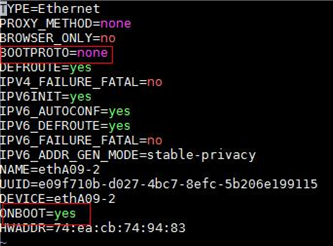
[root@node1 /]# vi /etc/sysconfig/network-scripts/ifcfg-ens34
3. Set the BOOTPROTO field to none to not specify a boot-up protocol and set the ONBOOT field to yes to activate the network interface at system startup.
Figure 1 Modifying the configuration file for a network interface
4. Execute the ifdown and ifup commands in sequence to reboot the network interface.
[root@node1 /]# ifdown ens34
[root@node1 /]# ifup ens34
5. Execute the ifconfig command to verify that the network interface is in up state.
Planning the networks
Network planning
Plan for the following networks:
· Calico network
Calico is an open source networking and network security solution for containers, Vims, and native host-based workloads. The Calico network is an internal network used for container interactions. The network segment of the Calico network is the IP address pool set for containers when the cluster is deployed. The default network segment is 177.177.0.0. You do not need to configure an address pool for the Calico network when installing and deploying the controller. The Calico network and MACVLAN network can use the same network interface.
· MACVLAN network
The MACVLAN network is used as a management network.
The MACVLAN virtual network technology allows you to bind multiple IPs and MAC addresses to a physical network interface. Some applications, especially legacy applications or applications that monitor network traffic, require a direct connection to the physical network. You can use the MACVLAN network driver program to assign a MAC address to the virtual network interface of each container, making the virtual network interface seem to be a physical network interface directly connected to the physical network. The physical network interface must be able to handle "promiscuous mode", supporting bundling of multiple MAC addresses to a physical interface.
The required management networks depend on the deployed components and application scenarios. Before deployment, plan the network address pools in advance.
Table 6 Network types and numbers used by components in the non-RDRS scenario
|
Component |
Network type |
Number of networks |
Remarks |
|
|
SeerEngine-DC |
MACVLAN (management network) |
1 |
N/A |
|
|
vBGP |
Management network and service network converged |
MACVLAN (management network) |
1*Number of vBGP clusters |
· Used for communication between the vBGP and SeerEngine-DC components and service traffic transmission. · Each vBGP cluster requires a separate management network. |
|
Management network and service network separated |
MACVLAN (management network) |
1*Number of vBGP clusters |
· Used for communication between the vBGP and SeerEngine-DC components. · Each vBGP cluster requires a separate management network. |
|
|
MACVLAN (service network) |
1*Number of vBGP clusters |
· Used for service traffic transmission. · Each vBGP cluster requires a separate service network. |
||
|
Digital Twin Network (DTN) |
MACVLAN (simulation management network) |
1 |
Used for simulation services. A separate network interface is required. |
|
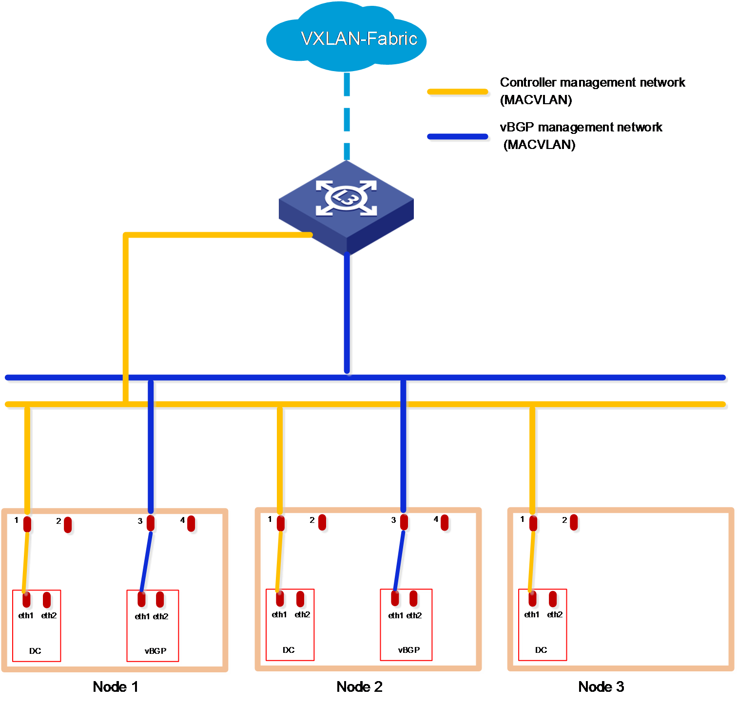
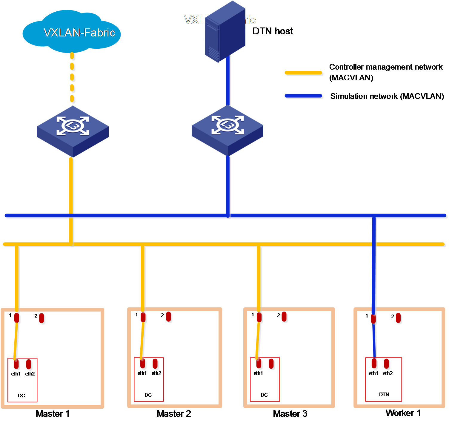
Figure 3 Cloud data center networks in the non-RDRS scenario (only DTN deployed)
|
|
IMPORTANT: · The SeerEngine-DC management network and vBGP management network are on different network segments. You must configure routing entries on the switches connected to the network interfaces to enable Layer 3 communication between the SeerEngine-DC management network and vBGP management network. · DTN does not support RDRS. · If the simulation management network and the controller management network are connected to the same switch, you must configure VPN instances. If the simulation management network and the controller management network are connected to different switches, make sure the switches are physically isolated. · Make sure the simulation management IP and the simulated device management IP are reachable to each other. |
IP address planning
Use Table 7 as a best practice to calculate IP addresses required for the networks.
Table 7 IP addresses required for the networks in the non-RDRS scenario
|
Component |
Network type |
Maximum team members |
Default team members |
Number of IP addresses |
Remarks |
||
|
SeerEngine-DC |
MACVLAN (management network) |
32 |
3 |
Number of cluster nodes + 1 (cluster IP) |
N/A |
||
|
vBGP |
Management network and service network converged |
MACVLAN (management network) |
2 |
2 |
Number of vBGP clusters*number of cluster nodes + Number of vBGP clusters (cluster IP) |
Each vBGP cluster requires a separate management network. |
|
|
Management network and service network separated |
MACVLAN (management network) |
2 |
2 |
Number of vBGP clusters*number of cluster nodes |
Each vBGP cluster requires a separate management network. |
||
|
MACVLAN (service network) |
2 |
2 |
Number of vBGP clusters*number of cluster nodes + Number of vBGP clusters (cluster IP) |
Each vBGP cluster requires a separate service network. |
|||
|
DTN |
MACVLAN (simulation management network) |
1 |
1 |
1 (cluster IP) |
A separate network interface is required. For management IP address assignment for DTN hosts, see H3C SeerEngine-DC Simulation Network Deployment Guide. |
||
Table 8 shows an example of IP address planning for a single vBGP cluster in a non-RDRS scenario where the management network and service network are converged .
Table 8 IP address planning for the non-RDRS scenario
|
Component |
Network type |
IP addresses |
Remarks |
|
SeerEngine-DC |
MACVLAN (management network) |
Subnet: 192.168.12.0/24 (gateway 192.168.12.1) |
N/A |
|
Network address pool: 192.168.12.101 to 192.168.12.132 |
|||
|
vBGP |
MACVLAN (management network) |
Subnet: 192.168.13.0/24 (gateway 192.168.13.1) |
Management network and service network are converged. |
|
Network address pool: 192.168.13.101 to 192.168.13.132 |
|||
|
DTN |
MACVLAN (simulation management network) |
Subnet: 192.168.12.0/24 (gateway 192.168.12.1) |
A separate network interface is required. For management IP address assignment for DTN hosts, see H3C SeerEngine-DC Simulation Network Deployment Guide. |
|
Network address pool: 192.168.12.133 to 192.168.12.133 |
Deploying the controller
1. Log in to Unified Platform. Click System > Deployment.
2. Obtain the SeerEngine-DC installation packages. Table 9 provides the names of the installation packages. Make sure you select installation packages specific to your server type, x86 or ARM.
|
Component |
Installation package name |
Remarks |
|
SeerEngine-DC |
· x86: SeerEngine_DC-version-MATRIX.zip · ARM: SeerEngine_DC-version-ARM64.zip |
Required |
|
vBGP |
· x86: vBGP-version.zip · ARM: vBGP-version-ARM64.zip |
Optional |
|
DTN |
· x86: SeerEngine_DC_DTN-version.zip · ARM: SeerEngine_DC_DTN-version-ARM64.zip |
Optional, for providing simulation services |
|
|
IMPORTANT: · For some controller versions, the installation packages are released only for one server architecture, x86 or ARM. · The DTN version must be consistent with the SeerEngine-DC version. · ARM servers do not support multi-vBGP clusters. |
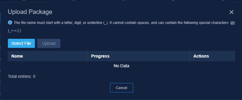
3. Click Upload , click Select File in the dialog box that opens, select an installation package, and then click Upload to upload the installation package. After the upload finishes, click Next.
Figure 4 Uploading an installation package
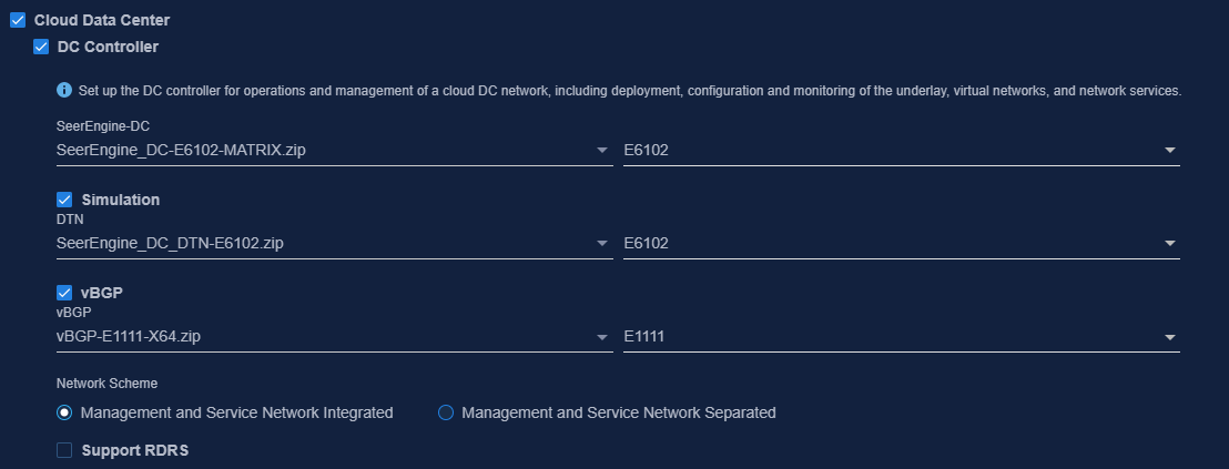
4. Select Cloud Data Center and then select DC Controller. To deploy the vBGP component simultaneously, select vBGP and select a network scheme for vBGP deployment. To deploy the DTN component simultaneously, select Simulation. Then click Next.
Figure 5 Selecting components
|
|
CAUTION: To avoid malfunction of simulation services, do not delete the worker node on which DTN has been deployed on the Matrix cluster deployment page. |
5. Configure the MACVLAN networks and add the uplink interfaces according to the network plan in "Planning the network."
To use simulation services, configure the network settings as follows:
¡ Configure a separate MACVLAN network for the DTN component. Be sure that the subnet IP address pool for the network contains a minimum of one IP address.
¡ If the servers are in standard configuration, the DTN component must have an exclusive use of a worker node server. If the servers are in high-end configuration, the DTN component can have an exclusive use of a worker node server or be deployed on the same master node with a controller. In this example, the DTN component is deployed on a worker node residing on a high-end server.
Figure 6 Configuring a MACVLAN management network for the SeerEngine-DC component
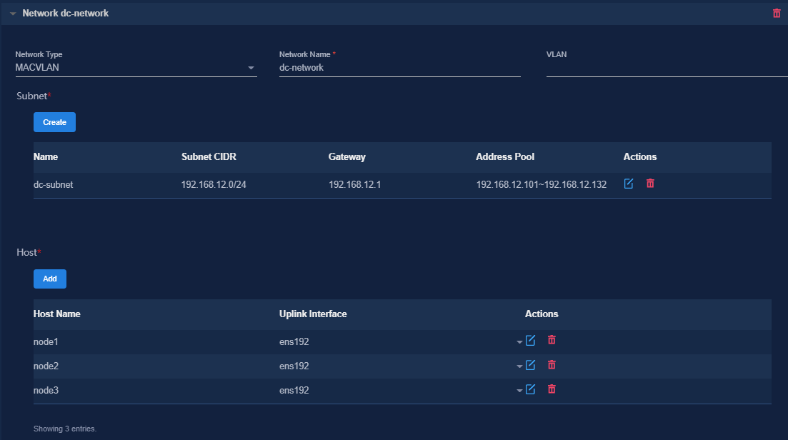
Figure 7 Configuring a MACVLAN management network for the DTN component
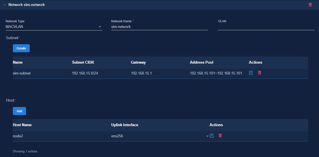
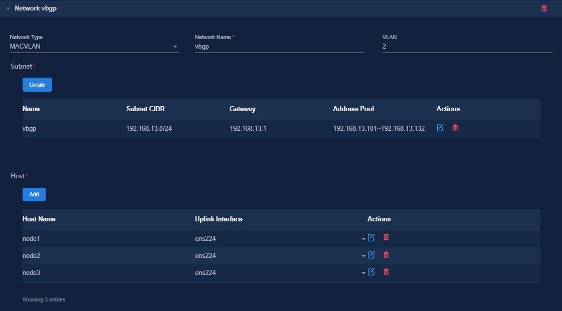
Figure 8 Configuring a MACVLAN management network for the vBGP component
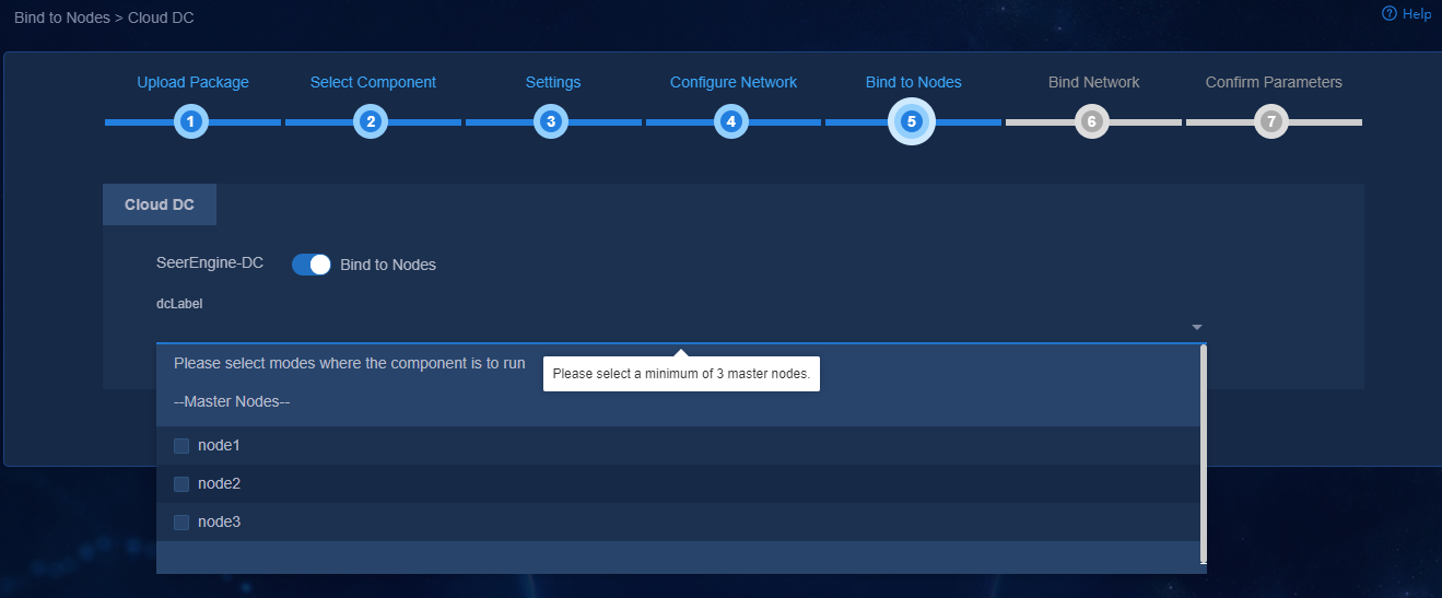
6. (Optional.) On the Bind to Nodes page, select whether to enable node binding. If you enable node binding, select a minimum of three master nodes to host and run microservice pods.
If a resource-intensive component such as Analyzer is required to be deployed simultaneously with the controller, enable node binding and bind the components to different nodes for better use of server resources.
Figure 9 Enabling node binding
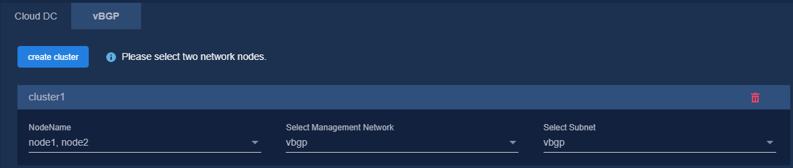
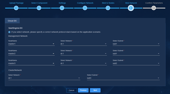
7. Bind networks to the components, assign IP address to the components, specify a network node for the service simulation network, and then click Next.
Figure 10 Binding networks (cloud DC)

Figure 11 Binding networks (vBGP)
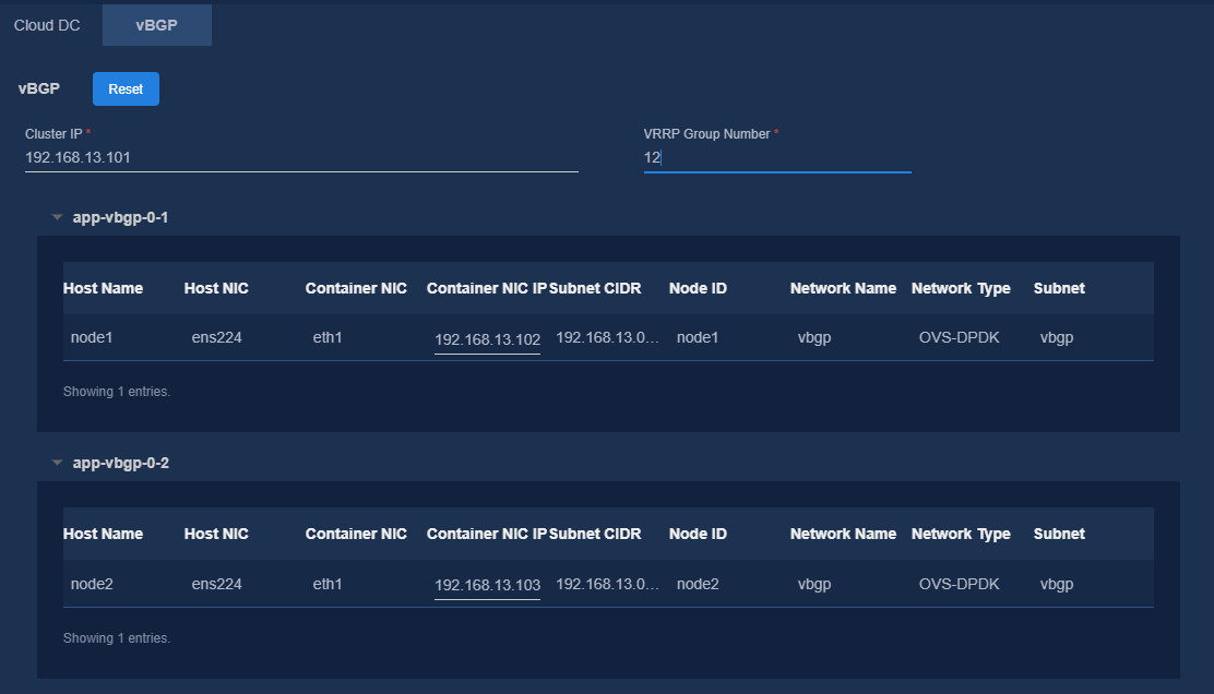
8. On the Confirm Parameters tab, verify network information and specify a VRRP group ID for the components.
A component automatically obtains an IP address from the IP address pool of the subnet bound to it. To modify the IP address, click Modify and then specify another IP address for the component. The IP address specified must be in the IP address range of the subnet bound to the component.
If vBGP is to be deployed, you are required to specify a VRRP group ID in the range of 1 to 255 for the components. The VRRP group ID must be unique within the same network.
Figure 12 Confirming parameters (SeerEngine-DC)
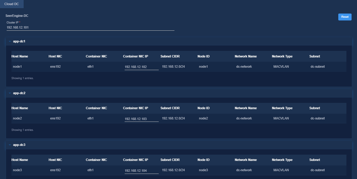
Figure 13 Confirming parameters (DTN)
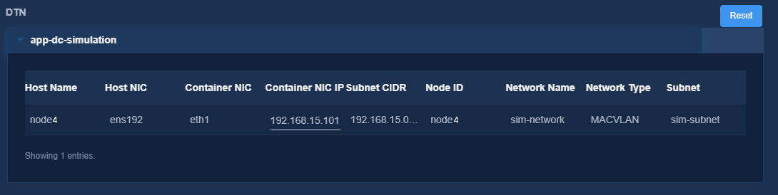
Figure 14 Confirming parameters (vBGP)
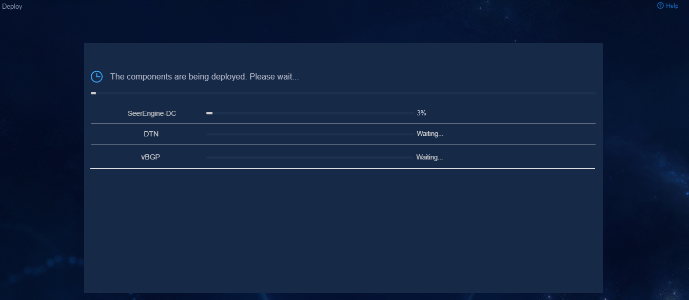
9. Click Deploy.
Figure 15 Deployment in progress
Accessing the controller
After the controller is deployed on Unified Platform, the controller menu items will be loaded on Unified Platform. Then you can access Unified Platform to control and manage the controller.
To access the controller:
1. Enter the address for accessing Unified Platform in the address bar and then press Enter.
By default, the login address is http://ip_address:30000/central/index.html.
¡ ip_address represents the northbound virtual IP address of Unified Platform.
¡ 30000 is the port number.
Figure 16 Unified Platform login page
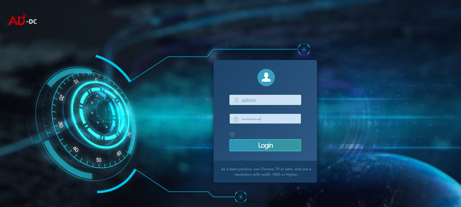
2. Enter the username and password, and then click Log in.
The default username is admin and the default password is Pwd@12345.
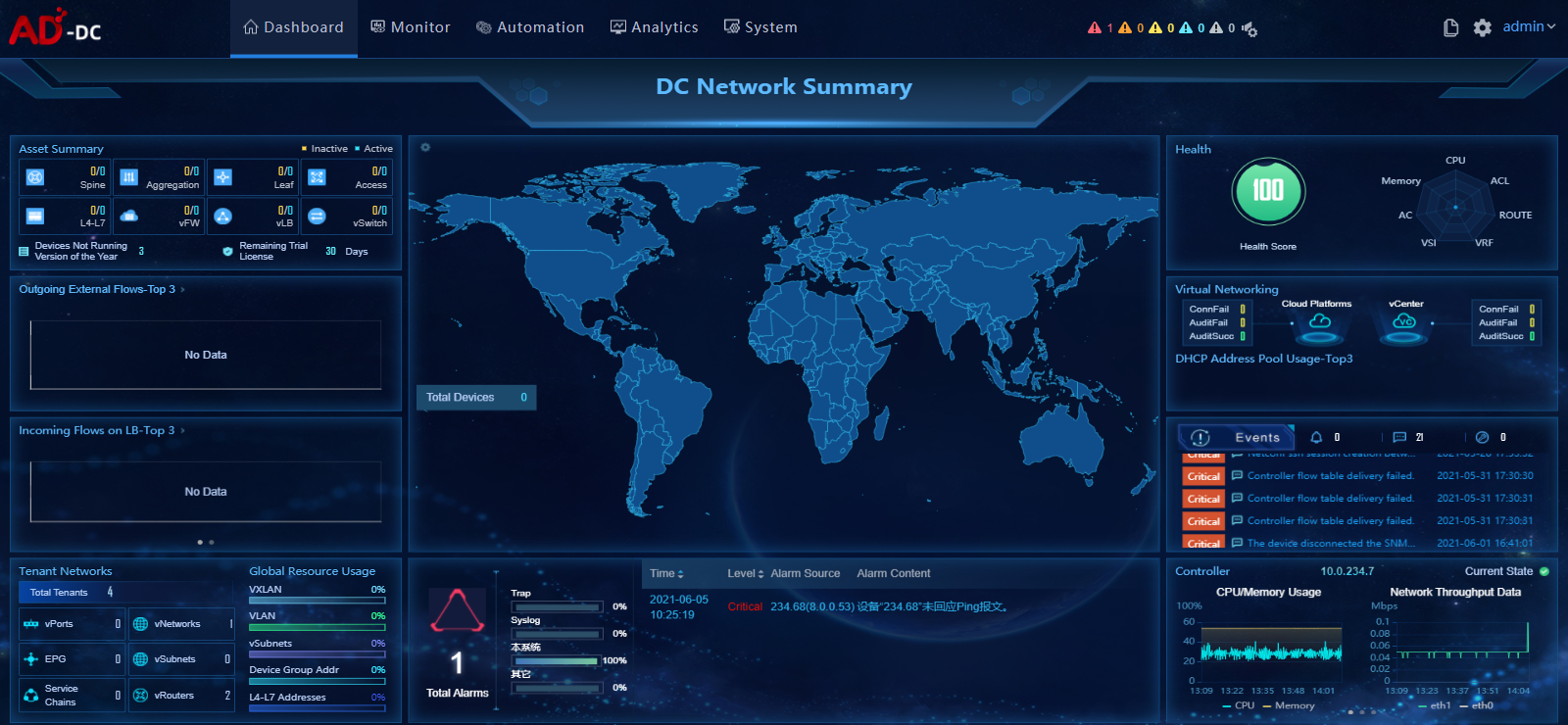
Figure 17 Unified Platform dashboard
Registering and installing licenses
After you install the controller, you can use its complete features and functions for a 180-day trial period. After the trial period expires, you must get the controller licensed.
Installing the activation file on the license server
For the activation file request and installation procedure, see H3C Software Products Remote Licensing Guide.
Obtaining licenses
1. Log in to Unified Platform. On the top navigation bar, click System, and then select License Management > License Information.
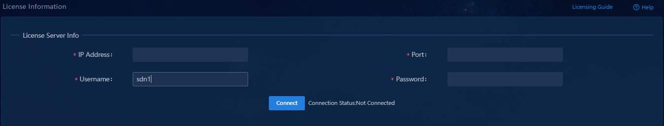
2. Configure the parameters for the license server as described in Table 10.
Table 10 License server parameters
|
Item |
Description |
|
IP Address |
Specify the IP address configured on the license server used for internal communication in the cluster. |
|
Port |
Specify the service port number of the license server. The default value is 5555. |
|
Username |
Specify the client username configured on the license server. |
|
Password |
Specify the client password configured on the license server. |
3. Click Connect to connect the controller to the license server.
The controller will automatically obtain licensing information after connecting to the license server.
Backing up and restoring the controller configuration
You can back up and restore the controller configuration on Unified Platform. For the procedures, see H3C Unified Platform Deployment Guide.
Upgrading the controller and DTN
|
|
CAUTION: · After the DTN component is upgraded, identify whether each simulation image needs to be upgraded. If a simulation image needs to be upgraded, delete it and upload the target one. · Upgrade SeerEngine-DC before DTN. The DTN version must be consistent with the SeerEngine-DC version after the upgrade. · The upgrade might cause service interruption. Be cautious when you perform this operation. · Before upgrading or scaling out Unified Platform or the controller, specify the manual switchover mode for the RDRS if the RDRS has been created. · Do not upgrade the controllers on the primary and backup sites simultaneously if the RDRS has been created. Upgrade the controller on a site first, and upgrade the controller on another site after data is synchronized between the two sites. · If the simulation network construction page has a display issue after the DTN component is upgraded, clear the browser cache and log in again. · After upgrading the DTN component from E6102 or earlier to E6103 or later, you must reinstall the operating system and reconfigure settings for DTN hosts and delete the original hosts from the simulation network and then reincorporate the hosts. For how to install the operating system and configure settings for DTN hosts, see H3C SeerEngine-DC Simulation Network Environment Deployment Guide. · After upgrading the DTN component from E6202 or earlier to E6203 or later, you must uninstall and reconfigure the DTN hosts and delete the original hosts from the simulation network and then reincorporate the hosts. For how to uninstall and configure DTN hosts, see H3C SeerEngine-DC Simulation Network Environment Deployment Guide. |
This section describes the procedure for upgrading and uninstalling the controller and DTN. For the upgrading and uninstallation procedure for Unified Platform, see H3C Unified Platform Deployment Guide.
The components can be upgraded on Unified Platform with the configuration retained.
|
|
NOTE: After upgrading the controller, manually clear the browser cache, and then log in again. |
To upgrade the controller and DTN:
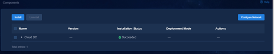
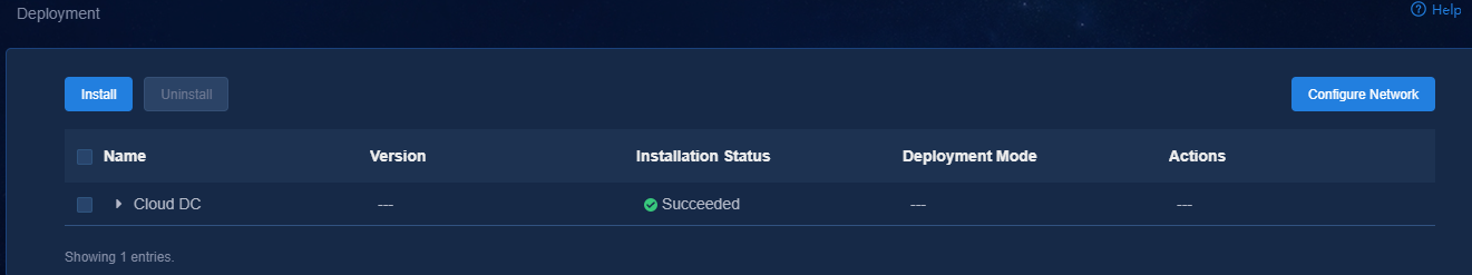
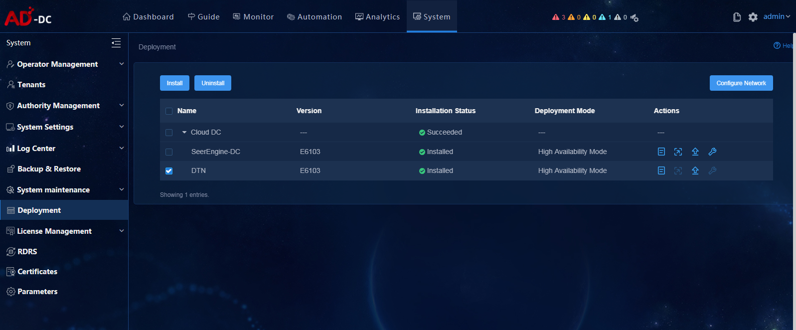
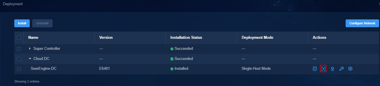
1. Log in to Unified Platform. Click System > Deployment.
Figure 18 Deployment page
2. Click the left chevron button ![]() for Cloud DC to
expand component information. Then upgrade SeerEngine-DC and DTN.
for Cloud DC to
expand component information. Then upgrade SeerEngine-DC and DTN.
a. Click the ![]() icon for the
SeerEngine-DC component to upgrade the SeerEngine-DC component.
icon for the
SeerEngine-DC component to upgrade the SeerEngine-DC component.
- If the controller already supports RDRS, the upgrade page is displayed.
# Upload and select the installation package.
# Select whether to enable Add Master Node-Component Bindings. The nodes that have been selected during controller deployment cannot be modified or deleted.
# Click Upgrade.
# If the upgrade fails, click Roll Back to roll back to the previous version.
- If the controller does not support RDRS, the system displays a confirmation dialog box with a Support RDRS option.
If you leave the Support RDRS option unselected, the upgrade page is displayed. Proceed with the upgrade.
If you select the Support RDRS option, the system will guide you to upgrade the component to support RDRS. For the upgrade procedure, see "Upgrading the controller to support RDRS."
b. Click the ![]() icon for the DTN
component to upgrade the DTN component.
icon for the DTN
component to upgrade the DTN component.
# Upload and select the installation package.
# Click Upgrade.
# If the upgrade fails, click Roll Back to roll back to the previous version.
Hot patching the controller
|
|
CAUTION: · Hot patching the controller might cause service interruption. To minimize service interruption, select the time to hot patch the controller carefully. · You cannot upgrade the controller to support RDRS through hot patching. · If you are to hot patch the controller after the RDRS is created, first specify the manual switchover mode for the RDRS. · Do not hot patch the controllers at the primary and standby sites at the same time after the RDRS is created. Only after the controller at a site is upgraded and data is synchronized, you can upgrade the controller at the other site. |
On the United Platform, you can hot patch the controller with the configuration retained.
To hot patch the controller:
1. Log in to Unified Platform. Click System > Deployment.
Figure 19 Deployment page
2. Click the left chevron button ![]() of the controller to
expand controller information, and then click the hot patching icon
of the controller to
expand controller information, and then click the hot patching icon ![]() .
.
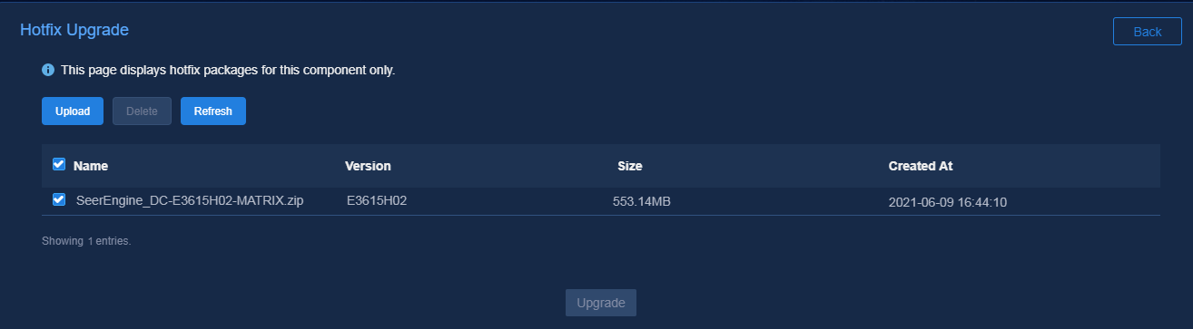
3. Upload the patch package and select the patch of the required version, and then click Upgrade.
Figure 20 Hot patching page
4. If the upgrade fails, click Roll Back to roll back to the previous version or click Terminate to terminate the upgrade.
Uninstalling SeerEngine-DC and DTN
When you uninstall the controller, DTN will be uninstalled simultaneously.
To uninstall SeerEngine-DC and DTN:
1. Log in to Unified Platform. Click System > Deployment.
2. Click the ![]() icon to the left of the controller name and then
click Uninstall.
icon to the left of the controller name and then
click Uninstall.
Figure 21 Uninstalling the controller and DTN
Uninstalling the DTN component only
The DTN component can be uninstalled separately.
To uninstall the DTN component only:
1. Log in to Unified Platform. Click System > Deployment.
2. Click the ![]() icon to the left of the DTN
component and then click Uninstall.
icon to the left of the DTN
component and then click Uninstall.
Figure 22 Uninstalling the DTN component
Uninstalling a hot patch
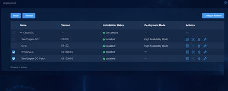
1. Log in to Unified Platform. Click System > Deployment.
2. Select a patch, and then click Uninstall.
Figure 23 Uninstalling a hot patch
Scaling out or in the controller
The controller can be scaled out from standalone mode to cluster mode or in cluster mode.
To scale in the controller, delete worker nodes in the cluster.
Scaling out the controller from standalone mode to cluster mode
To scale out the controller from standalone mode to cluster mode, add two master nodes on Matrix to form a three-host cluster with the existing master node. Then scale out Unified Platform and the controller sequentially.
To scale out the controller from standalone mode to cluster mode:
1. Scale out Matrix. For more information, see H3C Unified Platform Deployment Guide.
2. Scale out Unified Platform. For more information, see H3C Unified Platform Deployment Guide.
3. Add network bindings.
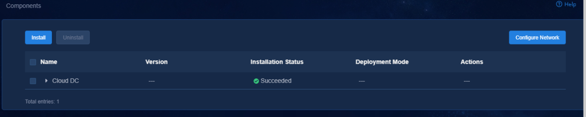
a. Log in to Unified Platform. On the top navigation bar, click System, and then select Deployment from the left navigation pane.
Figure 24 Deployment page
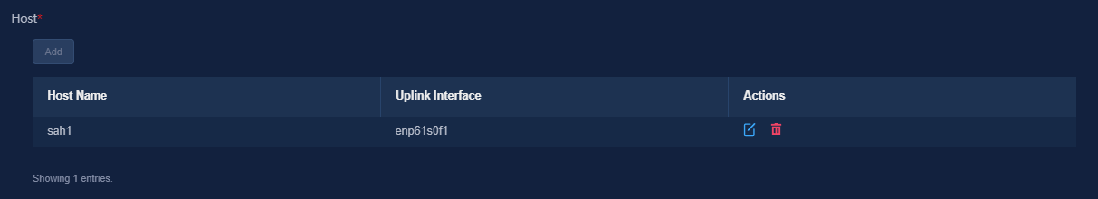
b. On the Deployment page that opens, click Configure Network to edit the MACVLAN network (management network). Click Add in the Host area, and then select the host to scale out and its uplink interface.
Figure 25 The MACVLAN network (management network)
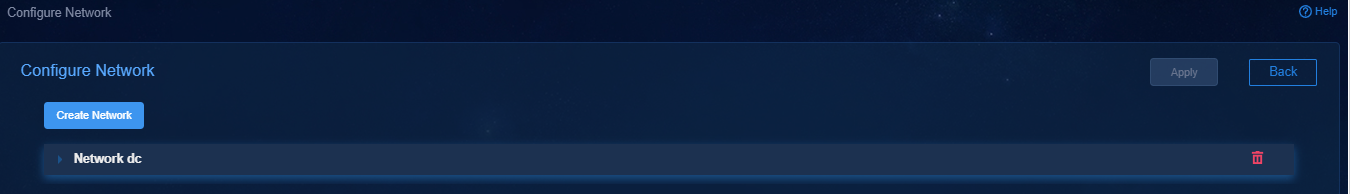
Figure 26 Host area
c. Click Apply.
4. Scale out the controller.
a. On the top navigation bar, click System, and then select Deployment from the left
navigation pane. Select the controller component to
scale out, and then click the ![]() icon in the Actions column.
icon in the Actions column.
b. On the Scale-Out page that opens, verify that the network name, subnet name, and uplink interface for the host to scale out are correct, and then click OK.
c. In the Host Information area, click Scale out.
Scaling out the controller in cluster mode
In cluster mode, scale out worker nodes one by one.
To scale out the controller in cluster mode:
1. Make sure you have added worker nodes to the Matrix cluster. For more information, see H3C Unified Platform Deployment Guide.
2. Log in to Unified Platform. On the top navigation bar, click System, and then select Deployment from the left navigation pane.
Figure 27 Deployment page

3. On the Deployment page that opens, click Configure Network to edit the MACVLAN network. Click Add in the Host area, select the host to scale out and its uplink interface, and then click Apply.
4. Log in to Unified Platform. On the top
navigation bar, click System, and then select Deployment from the left navigation pane. On the Deployment page that opens, select
the controller component to scale out, and then click the ![]() icon in the Actions column.
icon in the Actions column.
Figure 28 Deployment page
5. Select the host to scale out. Verify that the network name, subnet name, and uplink interface for the host are correct, and then click OK.
6. In the Host Information area, click Scale out. In cluster mode, you can scale out only one worker node at a time. Repeat this step to scale out multiple worker nodes.
Scaling in the controller in cluster mode
You can scale in the controller in cluster mode by deleting worker nodes in the cluster.
To scale in the controller in cluster mode:
1. Delete the host that has been scaled out. Only hosts scaled out in the cluster can be deleted.
a. Log in to Unified Platform. On the top navigation bar, click System, and then select Deployment from the left navigation pane.
b. On the Deployment
page that opens, select the component to scale in, and then click the ![]() icon in the Actions column.
icon in the Actions column.
c. On the Scale-Out page that opens, click the ![]() icon at the right of the host name in the
Host Information area. Click OK on the pop-up dialog box.
icon at the right of the host name in the
Host Information area. Click OK on the pop-up dialog box.
To avoid affecting existing services, back up the data before deleting a host.
2. Delete network bindings.
a. Log in to Unified Platform. On the top navigation bar, click System, and then select Deployment from the left navigation pane.
b. On the Deployment page that opens, click Configure Network in the upper right corner.
c. Click the ![]() icon
for the host in the Host area to delete the binding between the host and uplink interface.
icon
for the host in the Host area to delete the binding between the host and uplink interface.
3. Delete worker nodes.
a. Log in to Matrix. Click Deploy on the top navigation bar, and then select Cluster from the navigation pane.
b. In the Worker node area,
click the ![]() icon for a worker node, and then select Delete.
icon for a worker node, and then select Delete.
RDRS
About RDRS
A remote disaster recovery system (RDRS) provides disaster recovery services between the primary and backup sites. The controllers at the primary and backup sites back up each other. When the RDRS is operating correctly, data is synchronized between the site providing services and the peer site in real time. When the service-providing site becomes faulty because of power, network, or external link failure, the peer site immediately takes over to ensure service continuity.
The RDRS supports the following switchover modes:
· Manual switchover—In this mode, the RDRS does not automatically monitor state of the controllers on the primary or backup site. You must manually control the controller state on the primary and backup sites by specifying the Switch to Primary or Switch to Backup actions. This mode requires deploying Unified Platform of the same version on the primary and backup sites.
· Auto switchover with arbitration—In this mode, the RDRS automatically monitors state of the controllers. Upon detecting a controller or Unified Platform failure (because of site power or network failure), the RDRS automatically switches controller state at both sites by using the arbitration service. This mode also supports manual switchover. To use this mode, you must deploy Unified Platform of the same version at the primary and backup sites and the arbitration service as a third-party site.
The arbitration service can be deployed on the same server as the primary or backup site. However, when the server is faulty, the arbitration service might stop working. As a result, RDRS auto switchover will fail. As a best practice, configure the arbitration service on a separate server.
RDRS deployment procedure at a glance
1. Deploy the primary and backup sites.
2. Configure the RDRS settings for the controllers at the primary and backup sites.
3. Deploy the third-party arbitration service.
4. Create an RDRS.
Planning the network
|
|
CAUTION: · To use vBGP, make sure the primary and backup sites have a consistent MACVLAN network scheme and the same number of vBGP clusters. · In an RDRS scenario, if you configure DHCP relay on the management switch for automated underlay network deployment, you must specify the controller clusters' IPs of both the primary and backup sites as relay servers. · To deploy RDRS for the controllers, make sure the primary and backup sites uses different IP addresses for the RDRS networks. |
Table 11 Network types and numbers used by components at the primary/ backup site in the RDRS scenario
|
Component |
Network type |
Number of networks |
Remarks |
|
|
SeerEngine-DC |
MACVLAN (management network) |
1 |
N/A |
|
|
MACVLAN (RDRS network) |
1 |
· Used for carrying traffic for real-time data synchronization between the primary and backup sites. · Used for communication between the RDRS networks at the primary and backup sites · As a best practice, use a separate network interface. |
||
|
vBGP |
Management network and service network converged |
MACVLAN (management network) |
1*number of vBGP clusters |
· Used for communication between the vBGP and SeerEngine-DC components and service traffic transmission. · Each vBGP cluster requires a separate OVS-DPDK management network. |
|
Management network and service network separated |
MACVLAN (management network) |
1*number of vBGP clusters |
· Used for communication between the vBGP and SeerEngine-DC components. · Each vBGP cluster requires a separate OVS-DPDK management network. |
|
|
MACVLAN (service network) |
1*number of vBGP clusters |
· Used for service traffic transmission. · Each vBGP cluster requires a separate OVS-DPDK service network. |
||
Figure 29 Cloud DC networks in an RDRS scenario (vBGP deployed)
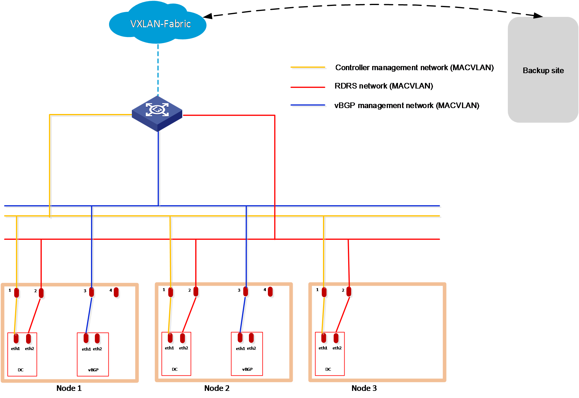
Table 12 IP addresses required for the networks at the primary/backup site in the RDRS scenario
|
Component |
Network type |
Maximum team members |
Default team members |
Number of IP addresses |
Remarks |
|
|
SeerEngine-DC |
MACVLAN (management network) |
32 |
3 |
Number of cluster nodes + 1 (cluster IP) |
N/A |
|
|
MACVLAN (RDRS network) |
32 |
3 |
Number of cluster nodes |
A separate network interface is required. |
||
|
vBGP |
Management network and service network converged |
MACVLAN (management network) |
2 |
2 |
Number of vBGP clusters*number of cluster nodes + Number of vBGP clusters (cluster IP) |
Each vBGP cluster requires a separate management network. |
|
Management network and service network separated |
MACVLAN (management network) |
2 |
2 |
Number of vBGP clusters*number of cluster nodes |
Each vBGP cluster requires a separate management network. |
|
|
MACVLAN (service network) |
2 |
2 |
Number of vBGP clusters*number of cluster nodes + Number of vBGP clusters (cluster IP) |
Each vBGP cluster requires a separate service network. |
||
Table 13 shows an example of IP address planning for a single vBGP cluster in an RDRS scenario where the management network and service network are converged.
Table 13 IP address planning for the RDRS scenario
|
Site |
Component |
Network |
IP address |
Remarks |
|
Primary site |
SeerEngine-DC |
MACVLAN (management network) |
Subnet: 192.168.12.0/24 (gateway 192.168.12.1) |
Make sure the primary and backup sites use different IP addresses for the RDRS networks and controllers. |
|
Address pool: 192.168.12.101 to 192.168.12.132 |
||||
|
MACVLAN (RDRS network) |
Subnet: 192.168.16.0/24 (gateway 192.168.16.1) |
As a best practice, use a separate network interface. |
||
|
Address pool: 192.168.16.101 to 192.168.16.132 |
||||
|
vBGP |
MACVLAN (management network) |
Subnet: 192.168.13.0/24 (gateway 192.168.13.1) |
N/A |
|
|
Address pool: 192.168.13.101 to 192.168.13.132 |
||||
|
Backup site |
SeerEngine-DC |
MACVLAN (management network) |
Subnet: 192.168.12.0/24 (gateway 10.0.234.254) |
Make sure the primary and backup sites use different IP addresses for the RDRS networks and controllers. |
|
Address pool: 192.168.12.133 to 192.168.12.164 |
||||
|
MACVLAN (RDRS network) |
Subnet: 192.168.16.0/24 (gateway 192.168.16.1) |
As a best practice, use a separate network interface. |
||
|
Address pool: 192.168.16.133 to 192.168.16.164 |
||||
|
vBGP |
MACVLAN (management network) |
Subnet: 192.168.13.0/24 (gateway 192.168.13.1) |
N/A |
|
|
Address pool: 192.168.13.101 to 192.168.13.132 |
Deploying the primary and backup sites
Restrictions and guidelines
Follow these restrictions and guidelines when you deploy the primary and backup sites and a site:
· The Unified Platform version, transfer protocol (HTTP or HTTPS), username and password, and IP version of the primary and backup sites must be the same.
· The arbitration service package on the site must match the Unified Platform version on the primary and backup sites.
· To use the auto switchover with arbitration mode, you must deploy a standalone Unified Platform as the site, and deploy arbitration services on the site.
· To use the allowlist feature in an RDRS scenario, you must add the IP addresses of all nodes on the backup site to the allowlist on the primary site, and add the IP addresses of all nodes on the primary site to the allowlist on the backup site.
Procedure
This procedure uses a separate server as the site and deploys Unified Platform in standalone mode on this site.
To deploy the primary and backup sites and a site:
1. Deploy Matrix on primary and backup sites and the site. For the deployment procedure, see H3C Unified Platform Deployment Guide.
2. Deploy Unified Platform on primary and backup sites. Specify the same NTP server for the primary and backup sites. For the deployment procedure, see H3C Unified Platform Deployment Guide.
Configuring the RDRS settings for the controllers at the primary and backup sites
Restrictions and guidelines
If the controller installed on the specified backup site does not support disaster recovery or is not in backup state, remove the controller and install it again.
Procedure
1. Log in to Unified Platform. Click System > Deployment.
2. Obtain the SeerEngine-DC installation package.
The SeerEngine-DC installation packages used for the primary and backup sites must be consistent in version and name.
3. Click Upload to upload the installation package and then click Next.
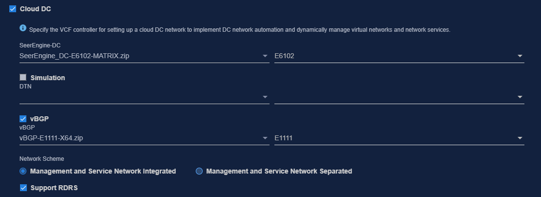
4. Select Cloud DC and controller. Then select the Support for RDRS network scheme. To deploy the vBGP component simultaneously, select vBGP and select the Management and service network converged network scheme for the vBGP component. Then click Next.
Figure 30 Selecting components
5. Configure the networks required by the components and add the uplink interfaces according to the network plan in "Planning the network."
¡ Configure a separate MACVLAN as the RDRS network.
¡ To deploy vBGP, configure an additional MACVLAN network. Make sure the network solutions are the same at the primary and backup sites.
The following shows network configurations at the primary site.
Figure 31 Configuring a MACVLAN management network for the controller

Figure 32 Configuring an RDRS network
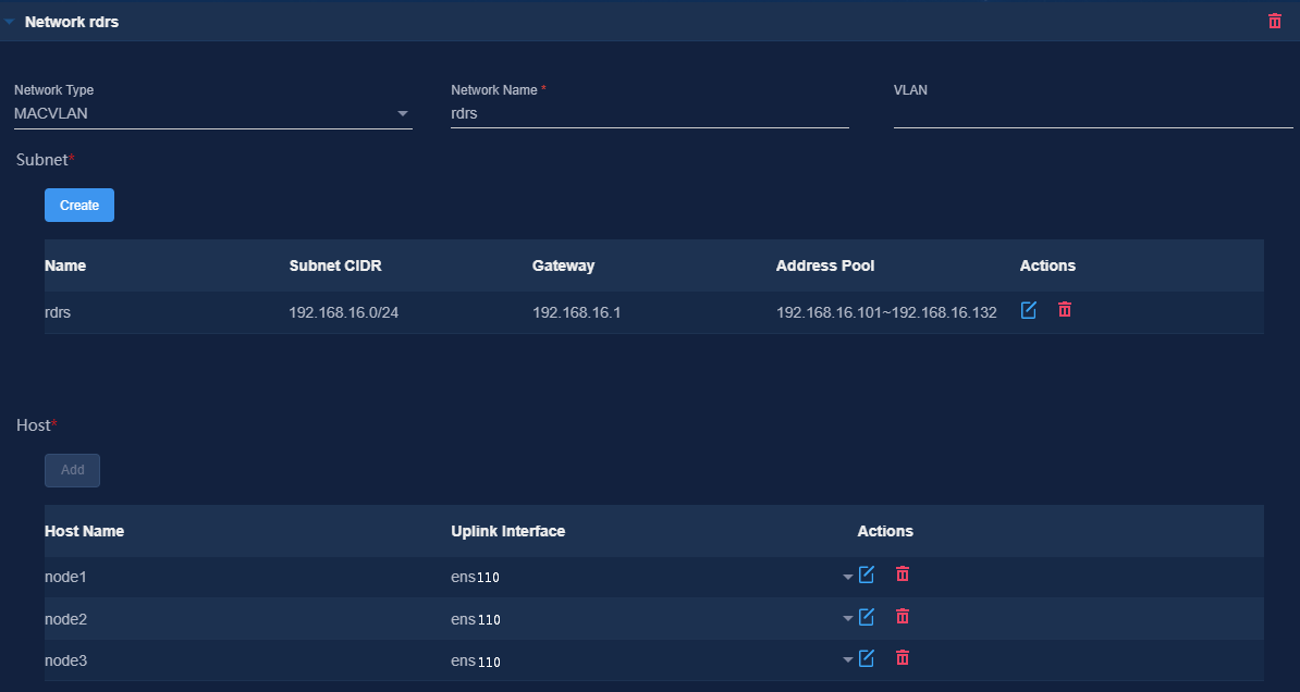
Figure 33 Configuring a vBGP MACVLAN network

6. (Optional.) On the Bind Node page, select whether to enable node binding. If you enable node binding, select a minimum of three master nodes to host and run microservice pods.
If a resource-intensive component such as Analyzer is required to be deployed simultaneously with the controller, enable node binding and bind the components to different nodes for better use of server resources.
7. Bind networks to the components and assign IP address to the components. Then click Next.
Figure 34 Binding networks (1)

8. On the Confirm Parameters page, verify network information and specify the RDRS status and a VRRP group ID for the components.
A component automatically obtains an IP address from the IP address pool of the subnet bound to it. To modify the IP address, click Modify and then specify another IP address for the component. The IP address specified must be in the IP address range of the subnet bound to the component.
Configure the RDRS status for the controllers:
¡ Select Primary from the Status in RDRS list for a controller at the primary site.
¡ Select Backup from the Status in RDRS list for a controller at the backup site.
If vBGP is to be deployed, you are required to specify a VRRP group ID in the range of 1 to 255 for the components. The VRRP group ID must be unique within the same network.
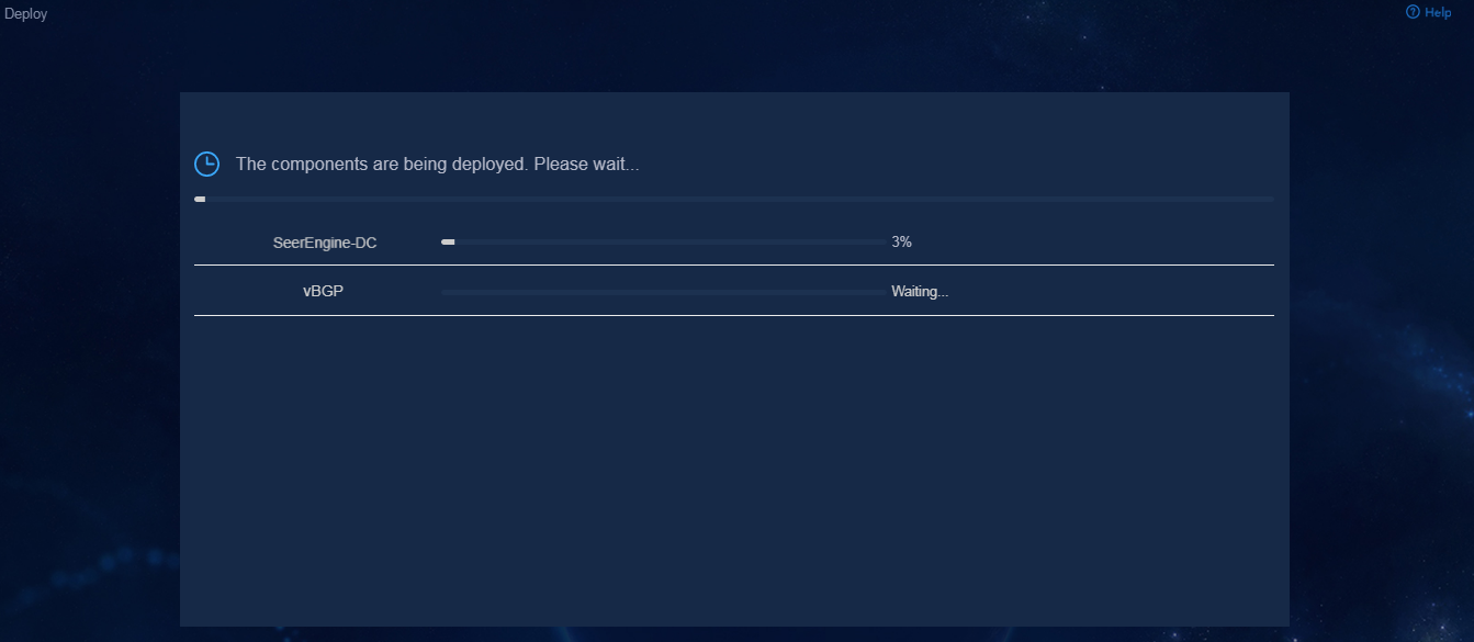
9. Click Deploy.
Figure 35 Deployment in progress
Deploying the third-party arbitration service
Preparing for deployment
Hardware requirements
The arbitration service can be deployed on a physical server. Table 14 describes the hardware requirements for a server to host the arbitration service.
Table 14 Hardware requirements for a server to host the arbitration service
|
Node name |
Node quantity |
Requirements |
|
Arbitration service |
1 |
· CPU: 2 cores, 2.0 GHz. · Memory: 16 GB or above. · RAID configuration: RAID 1, RAID 5, or RAID 10. · Drive configuration option 1: ¡ System drive: 2 × 480 GB SSDs configured in RAID1 that provide a minimum total drive size of 256 GB. ¡ etcd drive: 2 × 480 GB SSDs, configured in RAID1 that provide a minimum total drive size of 50 GB. (Installation path: /var/lib/etcd.) · Drive configuration option 2: ¡ System drive: 2 × 600 GB 7.2K RPM or above HDDs configured in RAID 1 that provide a minimum total drive size of 256 GB. ¡ etcd drive: 2 × 600 GB 7.2K RPM or above HDDs configured in RAID 1 that provide a minimum total drive size of 50 GB. ¡ Storage controller: 1 GB cache, power fail protected with a supercapacitor installed. · Network interface: 1 × 10 Gbps or above. |
Software requirements
As a best practice, deploy the third-party arbitration service on the H3Linux system.
Deploying the third-party arbitration service
Restrictions and guidelines
Make sure the application software package at the third-party site matches the SNA Center version at the primary and backup sites.
To avoid service failure, do not change the system time after the deployment.
Execution of the ifconfig command on network interfaces might cause loss of default routes. For correct deployment and operation of the third-party arbitration service, use the ifup and ifdown commands to configure network interfaces.
If multiple network interfaces exist on the node that hosts the third-party arbitration service, make sure all other network interfaces except the network interface used for the third-party arbitration service are down. If such a network interface is up, use the ifdown command to shut down it.
Pre-installation checklist
Before deploying the third-party arbitration service, check the environment against the checklist described in Table 15 to be sure that all requirements are met.
Table 15 Pre-installation checklist
|
Item |
Requirements |
|
|
Server |
Hardware |
The hardware of the server, including CPUs, memory, disks, and network interfaces, meets the requirements. |
|
Software |
· The version of the operating system is as required. · The system time settings are configured correctly. As a best practice, configure NTP for time synchronization and make sure the devices on the network synchronize to the same clock source. · Network settings, including IP addresses, have been configured correctly. |
|
|
Whether the third-party arbitration service has been installed in the system |
If the third-party arbitration service has been installed in the system, uninstall and reinstall the service again. |
|
|
Network interface |
Make sure the service has an exclusive use of a network interface. No subinterfaces or subnet IPs have been configured on the network interface. |
|
|
IP address |
The IP addresses of other interfaces on the node that hosts the third-party arbitration service must not be on the same network segment with the IP address used for the third-party arbitration service. |
|
|
Time zone |
For the arbitration service to function correctly, make sure the third-party arbitration service and the primary and backup sites are in the same time zone. You can use the timedatectl command to view the system time zone of each node. |
|
|
Power supply |
To protect the file system from irreversible damages (such as damage of the configuration file of the docker.service, etcd.service, or chrony.conf component), do not restart the node, power off the node forcibly, or reset the VM during the deployment and operation of the third-party arbitration service. |
|
Uploading the third-party arbitration service installation package
Obtain and copy the third-party arbitration service installation package to the installation directory on the server, or upload the installation package to the installation directory by using a file transfer protocol such as FTP.
The installation package is named in the SeerEngine_DC_ARBITRATOR-version.zip (applicable to an x86 system) or SeerEngine_DC_ARBITRATOR-version-ARM64.zip (applicable to an ARM system) format.
For some controller versions, the installation package is released only for one server architecture, x86 or ARM.
|
|
CAUTION: To avoid installation package damage, select the binary code if you use FTP or TFTP to upload or download the installation package. |
Installing the third-party arbitration service
The system supports the use of the root user or a non-root user to install the third-party arbitration service. As a best practice, use the root user for the installation. To use a non-root user to install the software package, you must use the root user to modify the configuration file by using the visudo command and assign installation permission to the non-root user by adding the following configuration items at the end of the configuration file:
[root@rdr01 ~]# visudo
<username> ALL=(root) NOPASSWD:/bin/bash
The following procedure uses the root user for the installation. To use a non-root user for the installation, execute the sudo ./install.sh command.
1. Access the directory where the third-party arbitration service installation package is saved and install the third-party arbitration service.
[root@rdr01 ~]# unzip SeerEngine_DC_ARBITRATOR-E3611.zip
[root@rdr01 ~]# cd SeerEngine_DC_ARBITRATOR-E3611/
[root@rdr01 SeerEngine_DC_ARBITRATOR-E3611]# ./install.sh
Installing...
2021-03-04 16:42:52 [info] -----------------------------------
2021-03-04 16:42:52 [info] SeerEngine_DC_ARBITRATOR-E3611
2021-03-04 16:42:52 [info] H3Linux Release 1.1.2
2021-03-04 16:42:52 [info] Linux 3.10.0-957.27.2.el7.x86_64
2021-03-04 16:42:52 [info] -----------------------------------
2021-03-04 16:42:53 [warn] To avoid unknown error, do not interrupt this installation procedure.
2021-03-04 16:42:57 [info] Checking environment...
2021-03-04 16:42:57 [info] Decompressing rdrArbitrator package...
Complete!
2. Verify that the installation is successful. If the installation succeeds, the result is displayed as follows:
[root@rdr01 SeerEngine_DC_ARBITRATOR-E3611]# jps |grep rdr
19761 rdrs3rd-1.0.0.jar
[root@rdr01 SeerEngine_DC_ARBITRATOR-E3611]# docker ps |grep etcd
31b40e2d521d rdr-arbitrator/etcd3rd:1.0.0 "/entrypoint.sh" 5 minutes ago Up 5 minutes etcd3rd
Uninstalling the third-party arbitration service
1. Access the CLI of the operating system and execute the following commands to uninstall the third-party arbitration service.
[root@rdr01 ~]# cd SeerEngine_DC_ARBITRATOR-E3611 //Directory where the third-party arbitration service package is decompressed
[root@rdr01 SeerEngine_DC_ARBITRATOR-E3611]# ./uninstall.sh
Uninstalling…
Uninstalling...
2021-03-04 16:50:09 [info] Stopping rdrArbitrator service...
2021-03-04 16:50:09 [info] stop container 31b40e2d521d in docker daemon
2021-03-04 16:50:20 [info] stop container 31b40e2d521d in docker daemon success
2021-03-04 16:50:20 [info] Deleting image rdr-arbitrator/etcd3rd:1.0.0 in docker daemon
2021-03-04 16:50:20 [info] Delete image rdr-arbitrator/etcd3rd:1.0.0 in docker daemon success
2021-03-04 16:50:20 [info] Deleting rdrArbitrator dir...
Complete!
2. Verify that the uninstallation is successful.
[root@rdr01 SeerEngine_DC_ARBITRATOR-E3611]# jps |grep rdr
[root@rdr01 SeerEngine_DC_ARBITRATOR-E3611]# docker ps |grep etcd
Upgrading the third-party arbitration service
|
|
CAUTION: Specify the manual switchover mode for the RDRS before the upgrade. |
To upgrade the third-party arbitration service, you must first uninstall the old version of third-party arbitration service and then upload and install the new version of third-party arbitration service installation package.
To upgrade the third-party arbitration service:
1. Access the primary site of the RDRS and specify the manual switchover mode.
2. Access the command line interface of the operating system and uninstall the third-party arbitration service. For the uninstallation procedure, see "Uninstalling the third-party arbitration service."
3. Obtain the new version of the third-party arbitration service installation package, and copy the package to the installation directory or upload the software package to the directory by using a file transfer protocol such as FTP. Then reinstall the third-party arbitration service. For the installation procedure, see "Installing the third-party arbitration service."
4. Log in to the primary site of the RDRS and change the switchover mode to automatic switchover with arbitration.
Creating an RDRS
Restrictions and guidelines
Do not create an RDRS at the primary and backup sites simultaneously.
Ensure network connectivity between the primary and standby sites during the RDRS creation process. If the RDRS fails to be created, first check the network connectivity.
You cannot back up or restore data on the RDRS configuration page, including the primary or backup site name, primary or backup site IP address, backup site username and password, and site IP address.
After an RDRS is created, you cannot change the internal virtual IP of the cluster at the primary and backup sites and the node IPs.
Procedure
1. Log in to SeerEngine-DC. Click System on the top navigation bar and then select RDRS from the navigation pane.
2. In the Site Settings area, configure the primary, backup, and site settings, and specify the switchover mode.
3. Click Connect.
If the heartbeat link is successfully set up, the RDRS site settings have been configured successfully.
After the sites are built successfully, the backup site will automatically synchronize its user, log, and backup and restore settings to the primary site, with the exception of the log content.
4. In the Disaster Recovery Components area, click Add to configure disaster recovery components.
Upgrading the controller to support RDRS
If the controller at the primary site does not support RDRS, you can upgrade it to support RDRS on Unified Platform with the configuration retained.
Restrictions and guidelines
The upgrade might cause service interruption. Be cautious when you perform the upgrade.
Only the controller at the primary site can be upgraded to support RDRS. If the controller installed at the standby site does not support RDRS or its RDRS status is not backup, uninstall and reinstall it.
In an RDRS scenario, if you configure DHCP relay on the management switch for automated underlay network deployment, you must specify the controller clusters' IPs of both the primary and backup sites as relay servers.
Procedure
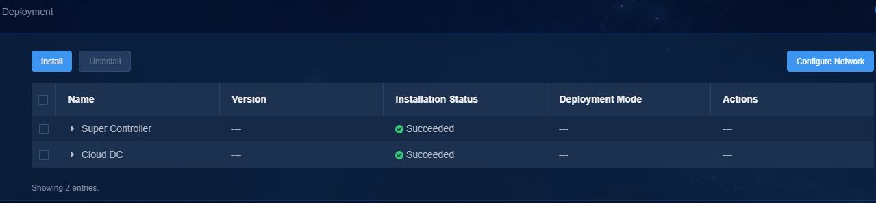
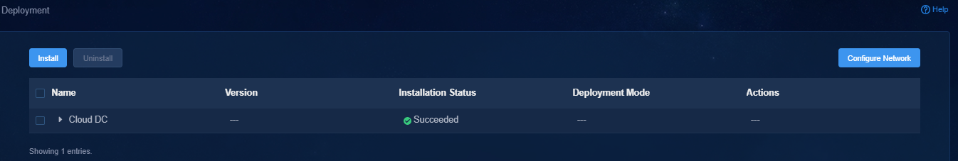
1. Log in to Unified Platform. Click System > Deployment.
Figure 36 Deployment page
2. Click the left chevron button ![]() for the component to
expand component information. Then click the
for the component to
expand component information. Then click the ![]() icon.
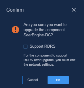
icon.
3. Select the Support RDRS option in the dialog box that opens and then click OK.
Figure 37 Support RDRS option
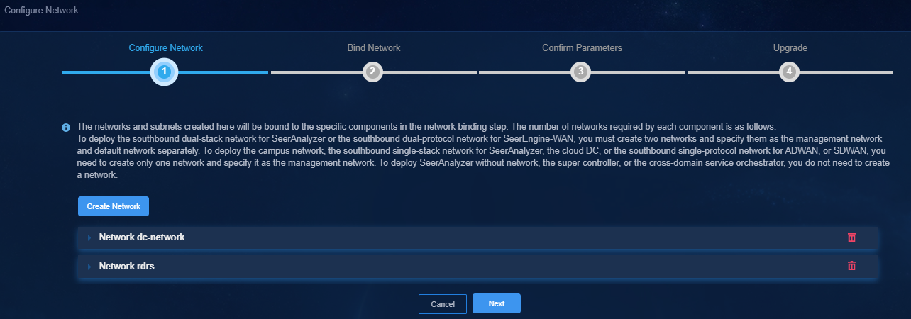
4. On the Configure Network page, create a MACVLAN network as the RDRS network. Make sure the RDRS network and the management network are on different network segments.
Figure 38 Configure Network page
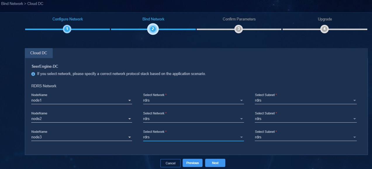
5. On the Bind Network page, bind the controller to the corresponding RDRS network and subnet, and then click Next.
Figure 39 Bind Network page
6. On the Confirm Parameters tab, verify that the IP addresses assigned to the RDRS network are correct, and then click Next.
7. On the Upgrade tab, upload and select the installation package, and then click Deploy.
8. If the upgrade fails, click Roll Back to roll back to the previous version.
Changing the license owner at an RDRS switchover
About this task
Use two sites site A and site B as an example. Configure a cluster with three servers at each site and set up a 3+3 RDRS system for the two sites to manage an SDN network. If 100 fixed-port switches are on the network, the system requires the following licenses.
Table 16 Licenses required in the 3+3 RDRS system
|
License name |
Quantity |
|
One DC controller server node license |
6 |
|
One fixed-port switch management license (NE license) |
100 |
Configure two clients, for example, sdn1 and sdn2 on the license server.
Figure 40 Configuring clients on the license server
Configure the RDRS system to use site A as the primary site and site B as the backup site. After the RDRS system is deployed. You can configure license server information on the license information page on the primary site and backup site separately.
Table 17 License server information
|
Site name |
Client name |
|
Site A |
sdn1 |
|
Site B |
sdn2 |
Figure 41 License server information page
Procedure
After an RDRS switchover occurs, you are required to change ownership of licenses. The following two methods can be used:
· Forcing offline the license client of the original primary site
· Specifying the new primary site as the owner of the licenses
Forcing offline the license client of the original primary site
1. When an RDRS switchover occurs, log in to the license server and force offline the license client of site A (original primary site) to release the licenses.
2. Log in to site B (new primary site) and configure the license server IP address, client name (sdn1), and password to be consistent with those on site A on the license information page. Then site B will connect the license server as the license client to obtain the controller and all NE licenses.
Specifying the new primary site as the owner of the licenses
License Server E1204 or later supports specifying the owner for licenses.
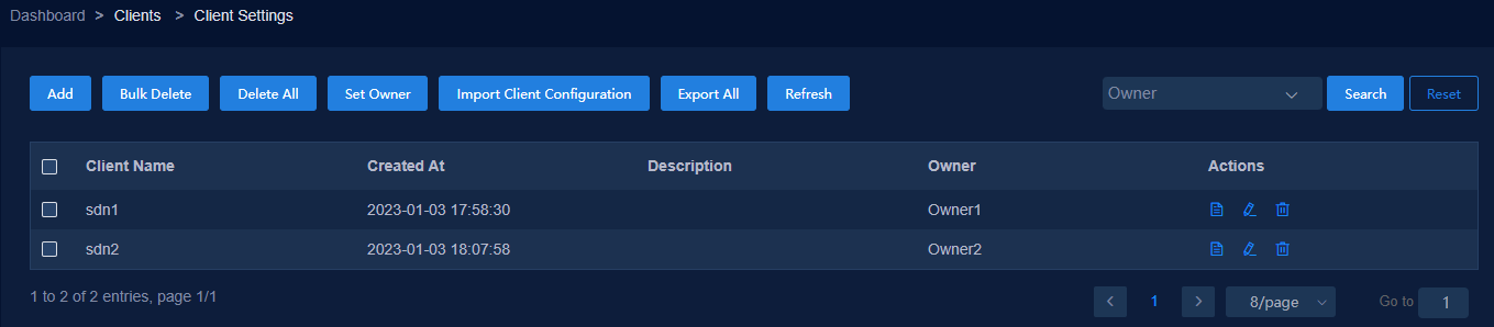
1. Access the license server. Specify two license clients, for example sdn1 and sdn2 and specify owners Owner1 and Owner2 for the clients, respectively.
2. After the RDRS system is deployed, configure license server information on the license information page of the primary and backup sites separately. Use the site, client, and owner relations are as shown in Table 18.
Table 18 Site, client, and owner relations
|
Site |
Client name |
Owner ID |
|
Site A |
sdn1 |
Owner1 |
|
Site B |
sdn2 |
Owner2 |
3. On the license server, assign the three controller licenses of Owner1 to site A, the three controller licenses of Owner2 to site B, and all NE licenses to Owner 1.
4. After an RDRS switchover occurs, reassign all NE licenses to Owner2 on the license server.
5. Disconnect and reconnect license server from the license information page of the new primary site (site B). Then site B obtains the three controller licenses and all NE licenses of Owner2.
Cluster deployment over a Layer 3 network
If the master nodes in a cluster are on different subnets, you deploy the cluster over a Layer 3 network.
In cluster deployment over a Layer 3 network, RDRS deployment, vBGP component deployment, and underlay IPv6 deployment are not supported.
The DTN component only supports deployment on a single node. The DTN component and simulation hosts (or simulated devices) support deployment over a Layer 3 network. For more information, see H3C SeerEngine-DC Simulation Network Deployment Guide.
|
|
NOTE: When VMware of an earlier version uses a VMXNET virtual network adapter, the TCP data packet length in the VXLAN frames might be calculated incorrectly. When using VMware to deploy a cluster over a Layer 3 network, use VMware ESXi 6.7P07 and 7.0U3 (7.0.3) or later. |
Network planning
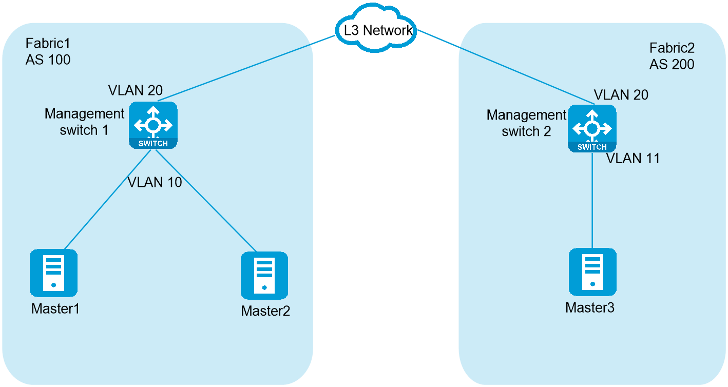
As shown in Figure 42, Master 1 and Master 2 are on the management network of Fabric 1, Master 3 is on the management network of Fabric 2. The management networks of Fabric 1 and Fabric 2 are on different subnets and communicate with each other at Layer 3. Plan the IP addresses as shown in Table 19 to deploy the cluster.
|
Component |
IP type |
IP address |
Remarks |
|
Unified Platform cluster |
IP address of Master node 1 |
192.168.10.102/24 |
The default gateway is 192.168.10.1 on management switch 1. |
|
IP address of Master node 2 |
192.168.10.103/24 |
||
|
IP address of Master node 3 |
192.168.110.104/24 |
The default gateway is 192.168.110.1 on management switch 2. |
|
|
Cluster internal virtual IP |
192.168.10.101/32 |
N/A |
|
|
Northbound service VIP |
192.168.10.100/32 |
N/A |
|
|
SeerEngine-DC |
Management network 1 (bound to master 1 and master 2) |
Subnet: 192.168.12.0/24 Network address pool: 192.168.12.101-192.168.12.132 |
MACVLAN network. The default gateway is 192.168.12.1 on management switch 1. |
|
Management network 2 (bound to master 3) |
Subnet: 192.168.112.0/24 Network address pool: 192.168.112.101-192.168.112.132 |
MACVLAN network. The default gateway is 192.168.112.1 on management switch 2. |
|
|
Management network 3 (cluster VIP) |
Subnet: 8.8.8.0/24 Network address pool: 8.8.8.8-8.8.8.8 |
You do not need to specify a gateway address on the switch. |
|
|
Management switch |
Management switch 1 |
Vlan-interface 10: 192.168.10.1/24, 192.168.12.1/24 Vlan-interface 20: 192.168.20.9/30 |
The Unified Platform node management network and SeerEngine-DC management network use the same NIC interface. |
|
Management switch 2 |
Vlan-interface 11: 192.168.110.1/24, 192.168.112.1/24 Vlan-interface 20: 192.168.20.10/30 |
The Unified Platform node management network and SeerEngine-DC management network use the same NIC interface. |
Prerequisites
Before cluster deployment, complete routing settings for the underlay to make sure the nodes can communicate with each other at Layer 3, and the nodes and the two gateway IP adresses can communicate with each other at Layer 3.
· On management switch 1
[device1] vlan 10
[device1-vlan10] quit
[device1] interface Vlan-interface10
[device1-Vlan-interface10] ip address 192.168.10.1 255.255.255.0
[device1-Vlan-interface10] ip address 192.168.12.1 255.255.255.0 sub
[device1-Vlan-interface10] quit
[device1] vlan 20
[device1-vlan20] quit
[device1] interface Vlan-interface20
[device1-Vlan-interface20] ip address 192.168.20.9 255.255.255.252
[device1-Vlan-interface20] quit
[device1] interface Ten-GigabitEthernet1/0/25
[device1-Ten-GigabitEthernet1/0/25] port link-mode bridge
[device1-Ten-GigabitEthernet1/0/25] port access vlan 10
[device1-Ten-GigabitEthernet1/0/25] quit
[device1] interface Ten-GigabitEthernet1/0/26
[device1-Ten-GigabitEthernet1/0/26] port link-mode bridge
[device1-Ten-GigabitEthernet1/0/26] port access vlan 10
[device1-Ten-GigabitEthernet1/0/26] quit
[device1] interface Ten-GigabitEthernet1/0/27
[device1-Ten-GigabitEthernet1/0/27] port link-mode bridge
[device1-Ten-GigabitEthernet1/0/27] port access vlan 20
[device1-Ten-GigabitEthernet1/0/27] quit
[device1] ip route-static 192.168.110.0 255.255.255.0 192.168.20.10
· On management switch 2
[device2] vlan 11
[device2-vlan11] quit
[device2] vlan 20
[device2-vlan20] quit
[device2] interface Vlan-interface11
[device2-Vlan-interface11] ip address 192.168.110.1 255.255.255.0
[device2-Vlan-interface11] ip address 192.168.112.1 255.255.255.0 sub
[device2-Vlan-interface11] quit
[device2] vlan 20
[device2-vlan20] quit
[device2] interface Vlan-interface20
[device2-Vlan-interface20] ip address 192.168.20.10 255.255.255.252
[device2-Vlan-interface20] quit
[device2] interface Ten-GigabitEthernet1/0/25
[device2-Ten-GigabitEthernet1/0/25] port link-mode bridge
[device2-Ten-GigabitEthernet1/0/25] port access vlan 11
[device2-Ten-GigabitEthernet1/0/25] quit
[device2] interface Ten-GigabitEthernet1/0/26
[device2-Ten-GigabitEthernet1/0/26] port link-mode bridge
[device2-Ten-GigabitEthernet1/0/26] port access vlan 20
[device2-Ten-GigabitEthernet1/0/26] quit
[device2] ip route-static 192.168.10.0 255.255.255.0 192.168.20.9
Deploying a Matrix cluster
This section describes only settings different from Layer 2 deployment. For other procedures, see H3C Unified Platform Deployment Guide.
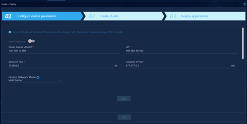
1. Set the cluster network mode to multisubnet.
Figure 43 Configuring cluster parameters
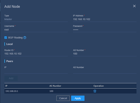
2. Configure BGP parameters for the nodes.
Table 20 Configuring BGP parameters for the nodes
|
Node |
IP address |
Local/Router ID |
Local/AS Number |
Peers/IP |
Peers/AS Number |
|
Master 1 |
192.168.10.102 |
192.168.10.102 |
100 |
192.168.10.1 |
100 |
|
Master 2 |
192.168.10.103 |
192.168.10.103 |
100 |
192.168.10.1 |
100 |
|
Master 3 |
192.168.110.104 |
192.168.110.104 |
200 |
192.168.110.1 |
200 |
Figure 44 Adding a node
3. Configure BGP on the switches connected to the cluster.
On management switch 1:
[device1] bgp 100
[device1-bgp] peer 192.168.10.102 as-number 100
[device1-bgp] peer 192.168.10.102 connect-interface Vlan-interface 10
[device1-bgp] peer 192.168.10.103 as-number 100
[device1-bgp] peer 192.168.10.103 connect-interface Vlan-interface 10
[device1-bgp] peer 192.168.110.1 as-number 200
[device1-bgp] peer 192.168.110.1 connect-interface Vlan-interface 20
[device1-bgp] address-family ipv4 unicast
[device1-bgp-ipv4] peer 192.168.10.102 enable
[device1-bgp-ipv4] peer 192.168.10.103 enable
[device1-bgp-ipv4] peer 192.168.110.1 enable
On management switch 2:
[device2] bgp 200
[device2-bgp] peer 192.168.110.104 as-number 200
[device2-bgp] peer 192.168.110.104 connect-interface Vlan-interface 11
[device2-bgp] peer 192.168.10.1 as-number 100
[device2-bgp] peer 192.168.10.1 connect-interface Vlan-interface 20
[device2-bgp] address-family ipv4 unicast
[device2-bgp-ipv4] peer 192.168.110.104 enable
[device2-bgp-ipv4] peer 192.168.10.1 enable
Deploying the controller at Layer 3
This section describes only settings different from Layer 2 deployment. For other procedures, see "Deploying the controller."
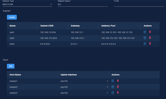
1. Create a MACVLAN network based on the IP address planning in Table 19.
Figure 45 Configuring network settings
2. Select networks.
Figure 46 Network bindings
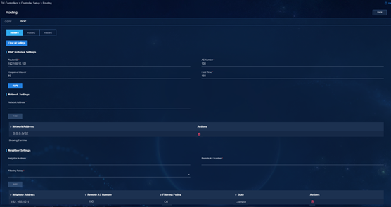
3. After the controller is deployed successfully, configure routing settings for each node. You can configure OSPF and BGP. In this example, BGP is configured.
Table 21 Routing settings on the nodes
|
Node |
BGP instance settings |
Network |
Neighbor settings |
||
|
Router ID |
AS Number |
Neighbor |
Remote AS |
||
|
Master 1 |
192.168.12.101 |
100 |
8.8.8.8/32 |
192.168.10.1 |
100 |
|
Master 2 |
192.168.12.102 |
100 |
8.8.8.8/32 |
192.168.10.1 |
100 |
|
Master 3 |
192.168.112.101 |
200 |
8.8.8.8/32 |
192.168.110.1 |
200 |
Figure 47 Routing settings on Master 1
4. Configure routing settings on the management switches.
On management switch 1:
[device1] bgp 100
[device1-bgp] peer 192.168.12.101 as-number 100
[device1-bgp] peer 192.168.12.101 connect-interface Vlan-interface 10
[device1-bgp] peer 192.168.12.102 as-number 100
[device1-bgp] peer 192.168.12.102 connect-interface Vlan-interface 10
[device1-bgp] address-family ipv4 unicast
[device1-bgp-ipv4] peer 192.168.12.101 enable
[device1-bgp-ipv4] peer 192.168.12.102 enable
On management switch 2:
[device2] bgp 200
[device2-bgp] peer 192.168.112.101 as-number 200
[device2-bgp] peer 192.168.112.101 connect-interface Vlan-interface 11
[device2-bgp] address-family ipv4 unicast
[device2-bgp-ipv4] peer 192.168.112.101 enable
Cluster 2+1+1 deployment
About cluster 2+1+1 deployment
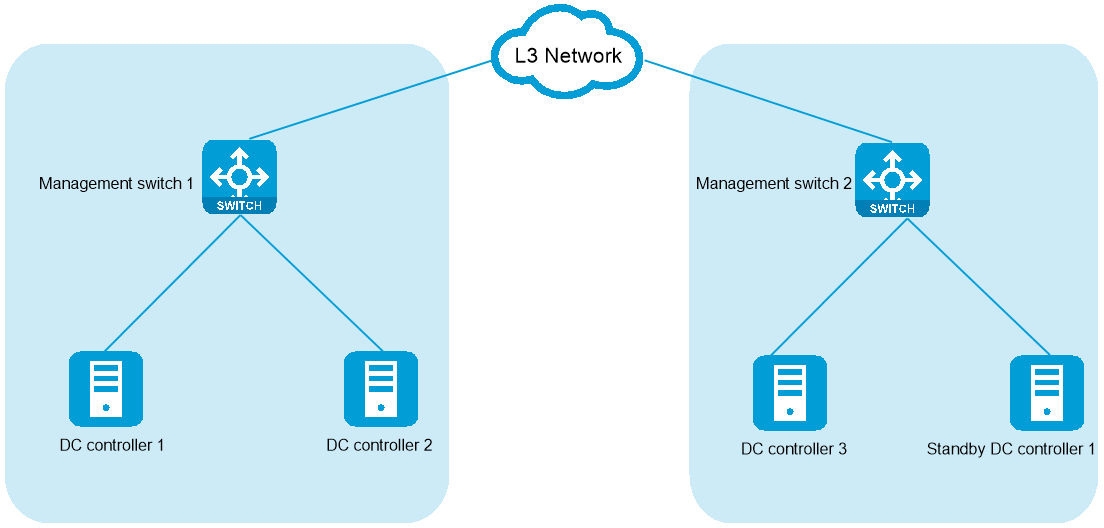
The cluster 2+1+1 mode is a low-cost failure recovery solution. To set up this solution, deploy the three nodes for setting up the controller cluster in two different cabinets or equipment rooms and reserve a standby node outside the cluster as a redundant node. When the cluster is operating correctly, leave the standby node unpowered. If two master nodes in the cluster fail at the same time, power on the standby node. The standby node will join the cluster quickly and the cluster service will have a fast recovery.
Figure 48 Cluster disaster recovery deployment
Deployment process
1. Prepare four servers: three used for setting up the Unified Platform cluster and one used as the standby server.
2. Install the four servers at different locations. As a best practice, install two of the servers for setting up the cluster in one cabinet (or equipment room), and the other server for setting up the cluster and the standby server in another cabinet (or equipment room).
3. Install Unified Platform on the three servers for setting up the cluster. For the installation procedure, see H3C Unified Platform Deployment Guide. As a best practice, assign IP addresses in the same network segment to the three servers and make sure they are reachable to each other.
4. Deploy the controller in the cluster. For the deployment procedure, see "Deploying the controller."
5. Install the Matrix platform on the standby server. Make sure the Matrix version is consistent with that installed on the three cluster servers. You are not required to deploy Unified Platform on the standby server.
Preparing for disaster recovery
1. Record the host name, NIC name, IP address, and username and password of the three nodes in the cluster.
2. Install Matrix on the standby node. The Matrix platform must be the same version as that installed on the cluster nodes.
|
|
IMPORTANT: · The drive letter and partitioning scheme of the standby node must be consistent with those of the cluster nodes. · If a Unified Platform patch version has been installed on the cluster nodes, use the following steps to install Matrix on the standby node for the standby node to have the same version of Matrix as the cluster nodes: 1. Install the Unified Platform base version (E06xx/E07xx) ISO image. 2. Uninstall Matrix from the operating system of the host. 3. Install the same version of Matrix as that in the Unified Platform patch version on the operating system of the host. |
Two node-failure recovery
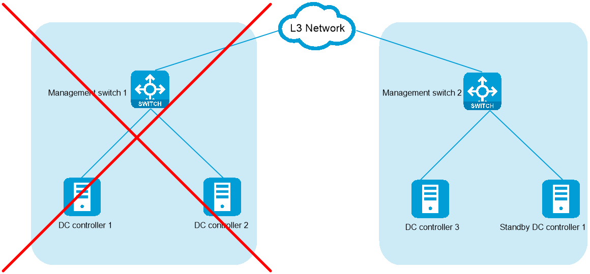
In a cluster with three leader nodes as shown in Figure 49, if two nodes (for example, controllers 1 and 2) fail at the same time, the cluster cannot operate correctly. Only controller 3 is accessible and will automatically enter emergency mode.
Figure 49 Failure of two nodes
To recover the cluster, perform the following steps:
1. Power on the standby node (without connecting it to the management network) and verify that Matrix has been installed on it. If not installed, see H3C Unified Platform Deployment Guide to install Matrix.
Do not configure any cluster-related settings on the standby node after Matrix is installed on it.
2. Verify that the host name, NIC name, IP address, and username and password of the standby node are exactly the same as those of the failed nodes, controller 1 in this example.
3. Disconnect the network connections of the failed controllers 1 and 2, and connect the standby node to the management network.
4. Log in to the Matrix Web interface of controller 3, and then click Deploy > Cluster. Click
the ![]() button for
controller 1 and select Rebuild
from the list. Then use one of the following methods to rebuild the node:
button for
controller 1 and select Rebuild
from the list. Then use one of the following methods to rebuild the node:
¡ Select and upload the same version of software package as installed on the current code. Then click Apply.
¡ Select the original software package version and then click Apply.
5. Log out to quit emergency mode. Then log in to the system again. As a best practice, use the VIP to access Matrix.
6. Repair or recover controller 2.
After the cluster resumes services, you can repair or recover controller 2.
¡ To use a new physical server to replace controller 2, you are required to log in to the Matrix page to perform repair operations.
¡ If the file system of the original controller 2 can be restored and started correctly, the controller can automatically join the cluster after you power on it. Then the cluster will have three correctly operating controllers.
|
|
CAUTION: · After the nodes are rebuilt, the standby node will join the cluster as controller 1. The original controller 1 cannot join the cluster directly after failure recovery. As a best practice, format the drive on the original controller 1, install Matrix on it, and use it as the new standby node. · If two controllers in the cluster are abnormal, you are not allowed to restart the only normal node. If the normal node is restarted, the cluster cannot be recovered through 2+1+1 disaster recovery. |
Network changes
About this task
If IP address conflict exists or the network plan needs to be changed, for example, equipment room relocation or subnet mask change after component deployment, you can change networks for the components. This section describes how to change network settings for the SeerEngine-DC and DTN components.
Procedure
|
|
CAUTION: · To change the IP address of a Matrix node in the RDRS scenario, you must first delete the RDRS system. · To do a network change for the controller and DTN component in the RDRS scenario, you must first delete the RDRS system. · Network change for a component can cause service interruption. Please be cautious. |
To edit network settings:
1. Log in to Unified Platform. Click System > Deployment.
Figure 50 Deployment page
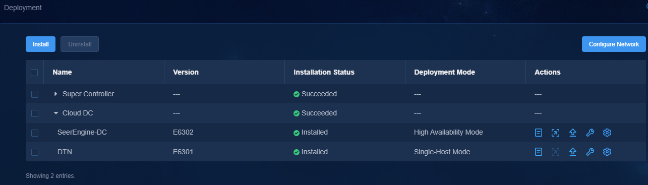
2. Click the left chevron button ![]() for the component to
expand component information.
for the component to
expand component information.
Editing network settings for the controller
1. Click the ![]() icon
for the SeerEngine-DC
component.
icon
for the SeerEngine-DC
component.
2. Select the target network.
Figure 51 Editing network settings
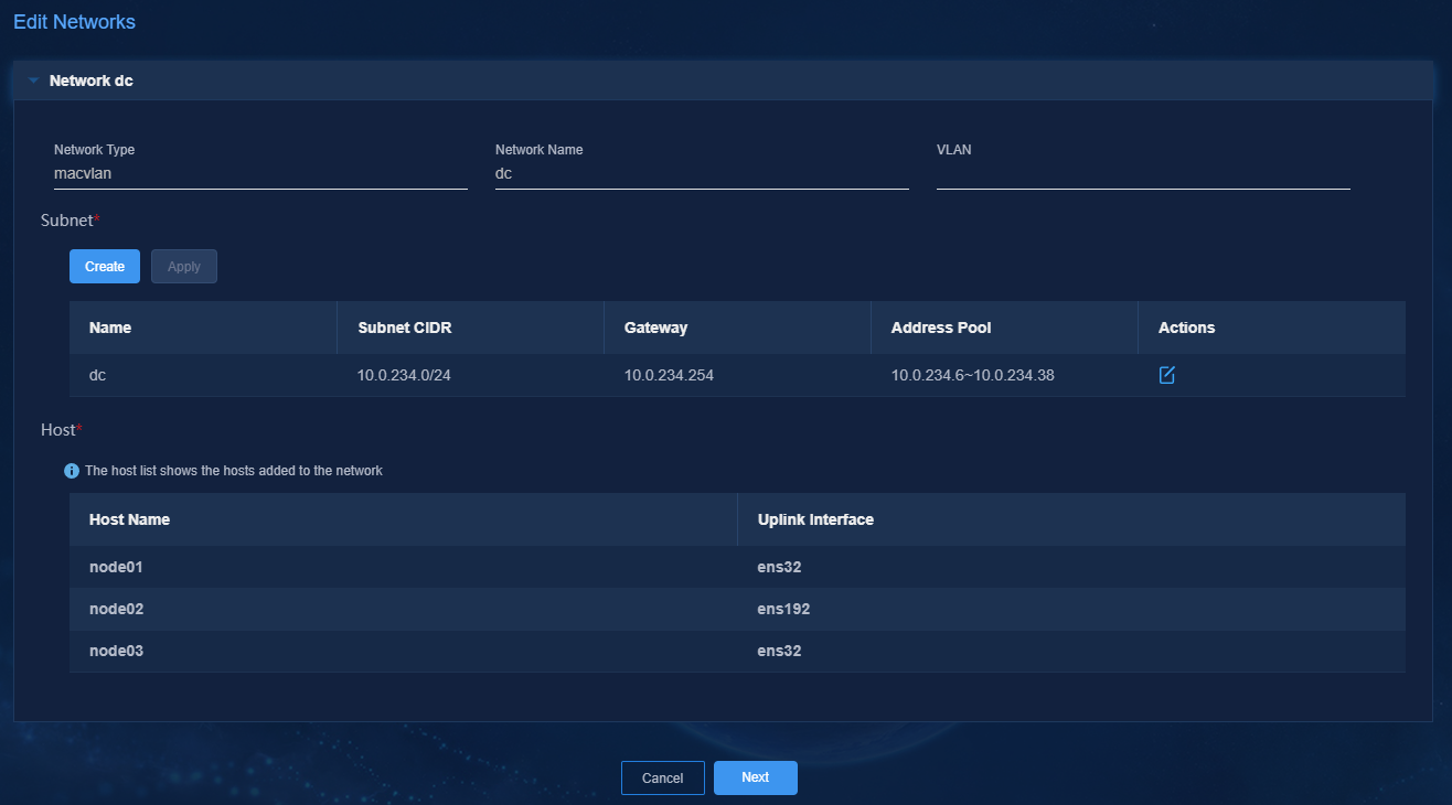
3. Click Create, and then create a subnet in the dialog box that opens.
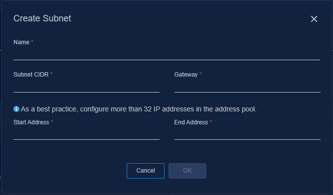
4. Click ![]() in the Actions column for a subnet, edit the name, CIDR, and gateway
for the subnet as needed, and then click OK.
in the Actions column for a subnet, edit the name, CIDR, and gateway
for the subnet as needed, and then click OK.
Figure 53 Editing a subnet
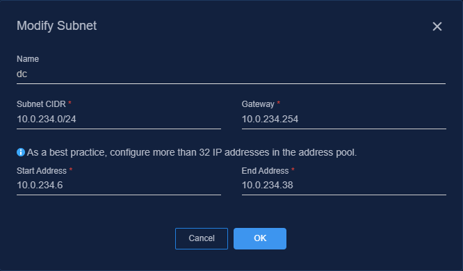
5. Click Next.
Figure 54 Confirming network parameters
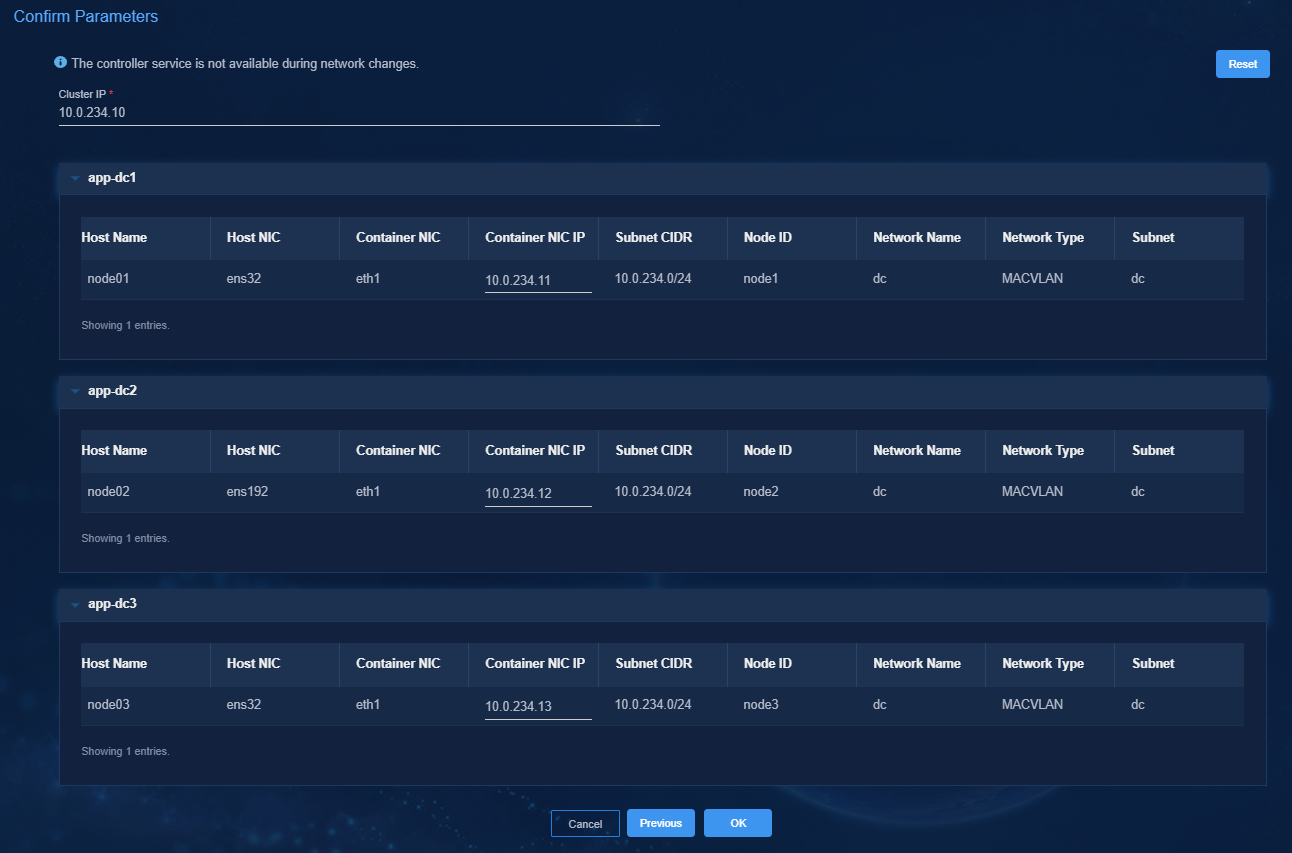
6. Review the parameters, and then click OK. The network editing progress is displayed on the page.
7. If network change fails, roll back the network settings or exit the network change process.
Editing network settings for the DTN component
1. Click the![]() icon for the DTN component.
icon for the DTN component.
2. Select a network.
3. Click Next.
4. Review the parameters, and then click OK. The network editing progress is displayed on the page.
5. If network change fails, roll back the network settings or exit the network change process.
Changing IP address settings after a network change
After a network change, you must edit some IP address related settings.
TFTP and Syslog services enabled
If you have enabled the TFTP and Syslog services on the Automation > Data Center Networks > Fabrics page, you must re-configure the IP address of the services.
Figure 55 Re-configuring the IP address for the TFTP and Syslog services
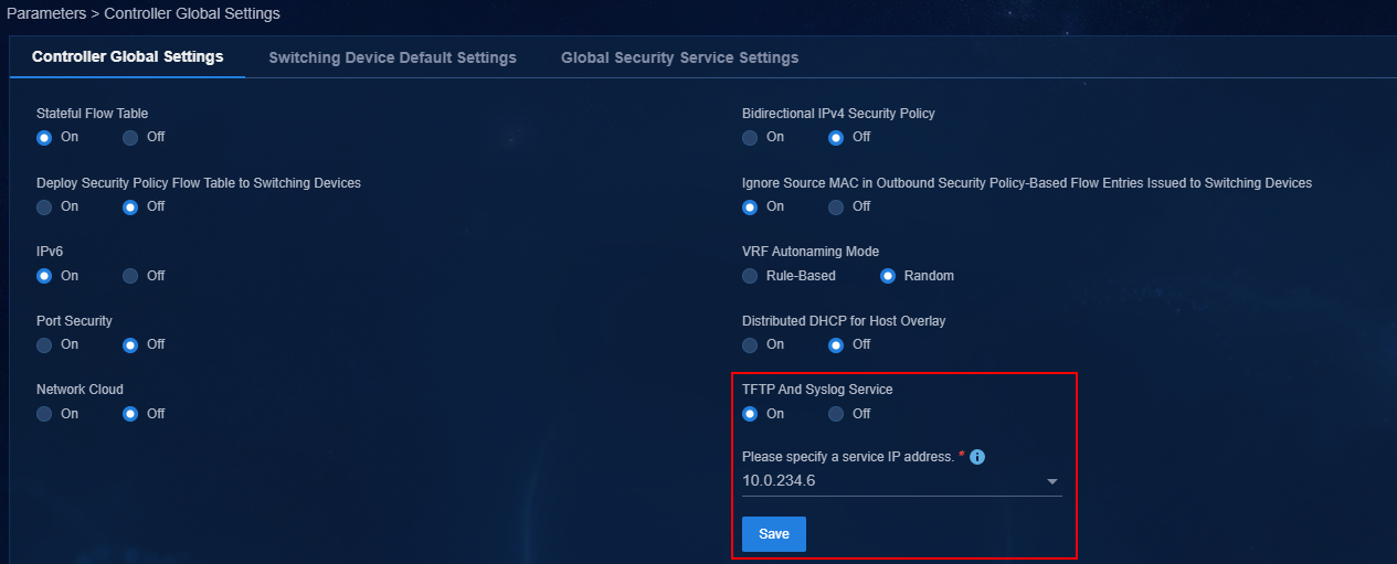
Deployment across a Layer 3 network
If you have configured routing settings on the System > System Maintenance > DC Controllers > Controller Setup page, you must re-configure routing settings after a network change.
Figure 56 Configuring routing settings
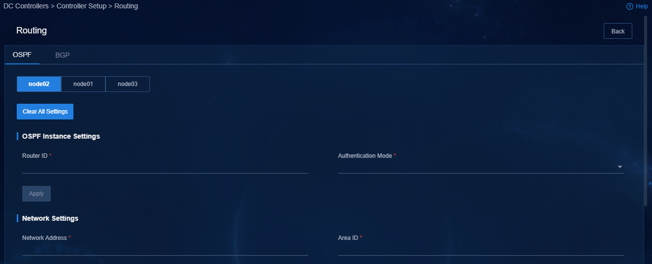
Updating the cluster IP through a configuration fragment
If an existing configuration fragment on the Automation > Data Center Networks > Fabrics > Auto Deployment > Configuration Fragment page contains the cluster IP for the controller, you must update the cluster IP of the controller after a network change and deploy the configuration fragment to the target device.
Figure 57 Configuration fragment page
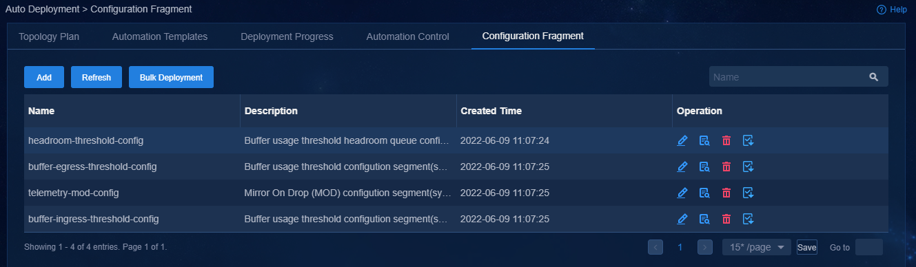
Figure 58 Editing device configuration fragment
The undo info-center loghost vpn-instance mgmt 192.168.89.10 command removes the controller cluster IP.
The info-center loghost vpn-instance mgmt 192.168.89.11 command sets a new controller cluster IP.
Figure 59 Deploying device configuration fragment
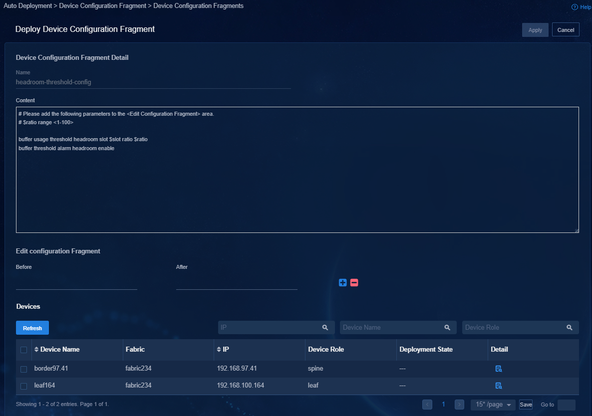
Configuring a region
If you have configured a region on the System > System Maintenance > DC Controllers > Controller Setup page, the system clears the managed subnets settings after a network change. You must re-configure the region.
Figure 60 Configuring a region
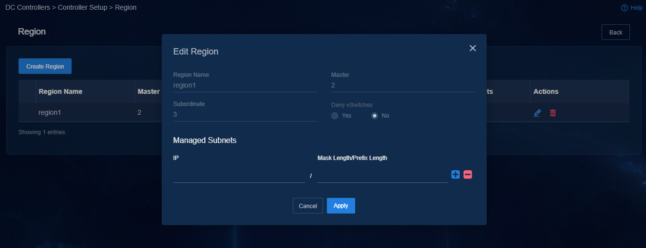
Editing the OpenStack plug-in settings
After a network change, you must edit the URL in the OpenStack Neutron plug-in, because the northbound virtual IP for the Matrix cluster has changed. For more information, see the OpenStack plug-in installation guide.
[SDNCONTROLLER]
url = http://127.0.0.1:30000
Configuring the license server
If the license server is deployed on a node in a Matrix cluster and the IP address of the node has changed, you must re-configure the license server after you edit network settings. For more information, see "Registering and installing licenses."
Data source management configuration
If you configured the close loop feature, you must re-configure basic information for DC data sources on the data source management page.
Figure 61 Managing data sources
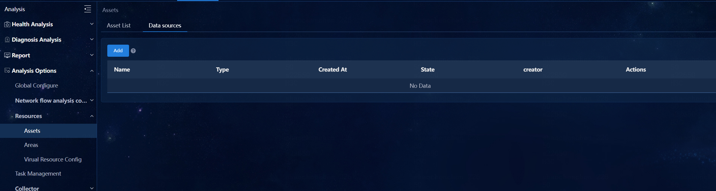
On the Analytics
> Analysis Options
> Resources > Assets
> Data Sources page,
click the Edit icon ![]() in the Actions column for the target data source, and then
change the IP address to the new Matrix northbound virtual IP
in the Actions column for the target data source, and then
change the IP address to the new Matrix northbound virtual IP
Figure 62 Editing basic configuration
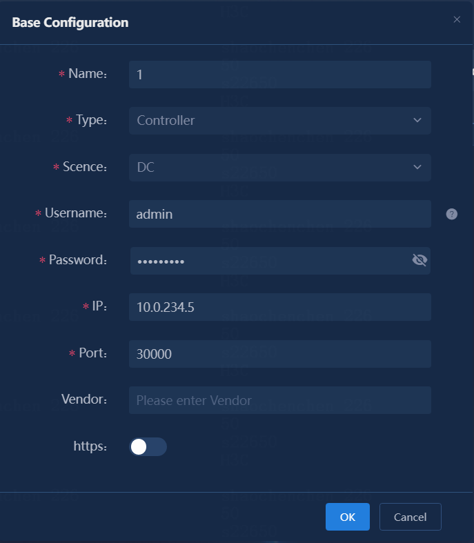
Configuring an RDRS
You must configure an RDRS system after you edit network settings. For more information, see "Creating an RDRS."
Checking the DTN network
For simulation to operate correctly after you edit DTN network settings, make sure the DTN component and DTN node are reachable to each other.
