- Table of Contents
- Related Documents
-
| Title | Size | Download |
|---|---|---|
| 01-Text | 791.34 KB |
Recommended BIOS configurations
BIOS configurations recommended for various workload patterns
Introduction to workload patterns
General Peak Frequency Compute mode
High Performance Computing mode
General Power Efficient Compute mode
Virtualization-Power Efficient mode
Virtualization–Performance mode
Transactional Application Processing mode
General Throughput Compute mode
Accessing the BIOS setup utility
Accessing the Advanced Power Management Configuration screen
About the BIOS
This document introduces the BIOS parameter configuration based on services running on the server, and describes the applicable scenarios and configuration instructions for related workloads.
Introduction to the BIOS
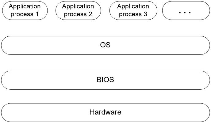
The Basic Input Output System (BIOS) is a firmware stored in the system ROM and acts as the most fundamental operating program loaded on the server hardware system. As shown in Figure 1, the BIOS interacts between the server hardware and the operating system (OS) to initialize hardware and prepare for OS operation.
The main functions of the BIOS include:
· Perform POST self-test.
· Detect input/output devices and bootable devices, including memory initialization, hardware scanning, boot device searching, and system boot.
· Provide advanced power management ACPI.
· Configure the RAID.
Figure 1 Location of the BIOS in the system
Applicable products
This guide is applicable to the following products:
· H3C UniServer R4300 G6
· H3C UniServer R4700 G6
· H3C UniServer R4700LE G6
· H3C UniServer R4900 G6
· H3C UniServer R4900LE G6
· H3C UniServer R4900 G6 Ultra
· H3C UniServer R5300 G6
· H3C UniServer R5500 G6 Intel
· H3C UniServer R6700 G6
· H3C UniServer R6900 G6
Applicable versions
This document is applicable to BIOS-6.00.XX.
Using this document
The information in this document is subject to change without notice due to product version upgrade or other reasons.
The information in this document might differ from your product if it contains custom configuration options or features.
Recommended BIOS configurations
Introduction
An application scenario configuration template is a collection of configuration options for deploying the BIOS settings to suit the expected application of the server. The BIOS provides multiple sets of configuration templates to help users deploy the most suitable BIOS settings according to different application scenarios. The configuration parameters in the template are recommended values for various application scenarios.
BIOS configurations recommended for various workload patterns
The recommended BIOS parameter configurations for various workload patterns are shown in Table 1 and Table 2. These tables display the dependencies associated with application scenario configuration templates. X indicates that the system does not have any requirements on the option in the template and you can edit the option as needed. The default value of X varies by device model. When the configuration template is reapplied, the X value in the template will be restored to the default value of the current model.
|
|
NOTE: · The BIOS may not display all the options corresponding to the table below, but the corresponding option settings will default to the values displayed in the table when the configuration template is used. · After you select a configuration template other than Custom, the corresponding options will be grayed out and cannot be modified. |
For more information about the configuration instructions and applicable scenarios for various types of workload patterns, see "Introduction to workload patterns."
Table 1 Dependencies of power consumption performance and application scenario configuration templates (1)
|
Dependency |
Virtualization-Power Efficient mode |
Virtualization–Performance mode |
Low Latency mode |
Fixed Turbo Frequency mode |
High Performance Computing mode |
General Peak Frequency Compute mode |
|
Link L0p Enable |
Enabled |
Disabled |
Disabled |
Disabled |
Disabled |
Disabled |
|
Link L1 Enable |
Enabled |
Disabled |
Disabled |
Disabled |
Disabled |
Disabled |
|
SNC |
Auto |
Auto |
Disabled |
Disabled |
Auto |
Disabled |
|
ADDDC Sparing |
Disabled |
Disabled |
Disabled |
Disabled |
Disabled |
Disabled |
|
Patrol Scrub |
Disabled |
Enable at End of POST |
Enable at End of POST |
Enable at End of POST |
Enable at End of POST |
Enable at End of POST |
|
Page Policy |
Adaptive |
Closed |
Closed |
Closed |
Closed |
Closed |
|
SpeedStep (Pstates) |
Enabled |
Enabled |
Enabled |
Enabled |
Enabled |
Disabled |
|
Energy Efficient Turbo |
Enabled |
Disabled |
Enabled |
Disabled |
Enabled |
Enabled |
|
Hardware P-States |
Out of Band Mode |
Native Mode |
Native Mode |
Out of Band Mode |
Native Mode |
Native Mode |
|
EPP profile |
Power |
Balanced Performance |
Balanced Performance |
Performance |
Balanced Performance |
Balanced Performance |
|
Enable Monitor MWAIT |
Enabled |
Enabled |
Enabled |
Disabled |
Enabled |
Disabled |
|
CPU C6 report |
Enabled |
Disabled |
Disabled |
Disabled |
Disabled |
Disabled |
|
Enhanced Halt State (C1E) |
Enabled |
Disabled |
Disabled |
Disabled |
Disabled |
Disabled |
|
Package C State |
C6(Retention) state |
C0/C1 state |
C0/C1 state |
C0/C1 state |
C0/C1 state |
C0/C1 state |
|
ENERGY_PERF_BIAS_CFG mode |
Power |
Performance |
Performance |
Performance |
Performance |
Performance |
|
Enable LP [Global] |
ALL LPs |
ALL LPs |
Single LP |
ALL LPs |
ALL LPs |
ALL LPs |
|
Hardware Prefetcher |
Disabled |
Enabled |
Enabled |
Enabled |
Enabled |
Enabled |
|
Adjacent Cache Prefetch |
Disabled |
Enabled |
Enabled |
Enabled |
Enabled |
Enabled |
|
DCU Streamer Prefetcher |
Disabled |
Enabled |
Enabled |
Enabled |
Enabled |
Enabled |
|
LLC Prefetch |
Enabled |
Disabled |
Enabled |
Disabled |
Disabled |
Disabled |
|
VMX |
Enabled |
Enabled |
Enabled |
Enabled |
Enabled |
Enabled |
|
When the SNC option is set to Auto, Auto represents SNC4 if the HBM CPU type is used. If the EMR XCC CPU type is used, Auto represents SNC2. In other cases, Auto represents Disabled. |
||||||
|
Dependency |
General Power Efficient Compute mode |
Transactional Application Processing mode |
General Throughput Compute mode |
Advanced Reliability mode |
Graphic Processing mode |
AI Optimized mode |
Custom mode |
|
Link L0p Enable |
Enabled |
Disabled |
Disabled |
Disabled |
Disabled |
Disabled |
X |
|
Link L1 Enable |
Enabled |
Disabled |
Disabled |
Disabled |
Disabled |
Disabled |
X |
|
SNC |
Auto |
Auto |
Disabled |
Disabled |
Auto |
Disabled |
X |
|
ADDDC Sparing |
Disabled |
Disabled |
Disabled |
Enabled |
Disabled |
Disabled |
X |
|
Patrol Scrub |
Disabled |
Enable at End of POST |
Enable at End of POST |
Enable at End of POST |
Enable at End of POST |
Enable at End of POST |
X |
|
Page Policy |
Adaptive |
Closed |
Closed |
Closed |
Closed |
Closed |
X |
|
SpeedStep (Pstates) |
Enabled |
Enabled |
Enabled |
Enabled |
Enabled |
Enabled |
X |
|
Energy Efficient Turbo |
Enabled |
Disabled |
Enabled |
Disabled |
Disabled |
Disabled |
X |
|
Hardware P-States |
Out of Band Mode |
Native Mode |
Native Mode |
Native Mode |
Native Mode |
Disabled |
X |
|
EPP profile |
Power |
Balanced Performance |
Balanced Performance |
Balanced Performance |
Balanced Performance |
Balanced Performance |
X |
|
Enable Monitor MWAIT |
Enabled |
Disabled |
Disabled |
Disabled |
Enabled |
Disabled |
X |
|
CPU C6 report |
Enabled |
Disabled |
Disabled |
Disabled |
Disabled |
Disabled |
X |
|
Enhanced Halt State (C1E) |
Enabled |
Disabled |
Disabled |
Disabled |
Disabled |
Disabled |
X |
|
Package C State |
C6(Retention) state |
C0/C1 state |
C0/C1 state |
C0/C1 state |
C0/C1 state |
C0/C1 state |
X |
|
ENERGY_PERF_BIAS_CFG mode |
Power |
Performance |
Performance |
Performance |
Performance |
Performance |
X |
|
Enable LP [Global] |
ALL LPs |
ALL LPs |
Single LP |
ALL LPs |
ALL LPs |
ALL LPs |
X |
|
Hardware Prefetcher |
Disabled |
Disabled |
Disabled |
Enabled |
Enabled |
Enabled |
X |
|
Adjacent Cache Prefetch |
Disabled |
Disabled |
Disabled |
Enabled |
Enabled |
Enabled |
X |
|
DCU Streamer Prefetcher |
Disabled |
Disabled |
Disabled |
Enabled |
Enabled |
Enabled |
X |
|
LLC Prefetch |
Enabled |
Enabled |
Enabled |
Disabled |
Disabled |
Disabled |
X |
|
VMX |
Disabled |
Enabled |
Enabled |
Enabled |
Disabled |
Enabled |
X |
Introduction to workload patterns
This chapter introduces the applicable scenarios and configuration instructions for each workload pattern.
|
|
NOTE: In this document, the BIOS configuration schemes for different application scenarios are universal solutions. For special requirements, configure the BIOS parameters according to your actual needs. |
The BIOS provides the following application scenario configuration templates.
Fixed Turbo Frequency mode
Application scenarios
Fixed Turbo Frequency is used for applications that lock to the turbo frequency.
Usage guidelines
The main implementation is achieved through out-of-band methods, and the operating system does not participate in frequency adjustment.
General Peak Frequency Compute mode
Application scenarios
General Peak Frequency Compute is used for application scenarios that do not require high overall system performance.
Usage guidelines
By turning off the turbo boost switch, the operating system takes control of frequency adjustment, allowing the system to run at the base frequency.
Low Latency mode
Application scenarios
Low Latency is suitable for applications with high requirements for computational latency, such as systems with large data volume, real-time monitoring of service data, and wide message transmission.
Usage guidelines
This scenario requires the system to respond quickly to maximize the real-time value of the data. By disabling power-saving options, turning off the delay-inducing hyper-threading technology, and allowing the operating system to control frequency adjustments, this mode enables the system CPUs to operate at the turbo frequency.
High Performance Computing mode
Application scenarios
High Performance Computing mode is used for applications that require intensive computation.
Usage guidelines
The High Performance Computing mode is similar to the low latency mode, but is often used in concurrent multitasking scenarios. As a best practice, enable hyper-threading when you use this mode. By disabling energy-saving options, the operating system takes control of frequency adjustment, allowing the system to run at turbo frequency.
General Power Efficient Compute mode
Application scenarios
General Power Efficient Compute is used for application scenarios with high energy consumption requirements.
Usage guidelines
The General Power Efficient Compute mode is similar to the Virtualization-Power Efficient mode, but does not require enabling virtualization options. Enabling energy-saving options allows the CPU cores to enter sleep state. When the system switch between different states, the latency may increase and performance degrade may occur.
Virtualization-Power Efficient mode
Application scenarios
Virtualization-Power Efficient is used in virtualized environments and for application scenarios with high energy consumption requirements.
Usage guidelines
This mode enables all options related to virtualization to support virtualization features. By enabling energy-saving options and sacrificing the maximum operating speed, the system can achieve lower power consumption in idle state.
Virtualization–Performance mode
Application scenarios
The Virtualization–Performance mode is used in virtualized environments and is suitable for applications that require high performance.
Usage guidelines
This mode enables all options related to virtualization to support virtualization features. By disabling energy-saving options, the system obtains a higher operating speed and better performance.
Advanced Reliability mode
Application scenarios
The Advanced Reliability mode is used for applications with high requirements for system stability and maintainability.
Usage guidelines
This mode enables advanced RAS options and disables power-saving options to reduce the system's response processing time for handling errors. As a best practice, use X4 memory modules.
Transactional Application Processing mode
Application scenarios
The Transactional Application Processing mode is used for upper-level service scenarios, such as database systems.
Usage guidelines
This mode has the same settings as the high performance computing template, which is suitable for most scenarios. If the service data being targeted has a certain degree of randomness and the dataset is large, disable prefetching and NUMA memory access as a best practice. This is beneficial for the application to execute actual service operations.
General Throughput Compute mode
Application scenarios
The General Throughput Compute mode is used in scenarios that require maximum sustainable throughput.
Usage guidelines
By disabling the prefetch option and turning off the turbo boost switch, this mode reduces the number of stalled cycles caused by CPU waiting, balances peak frequency and throughput requirements, and improves IO throughput.
Graphic Processing mode
Application scenarios
The Graphic Processing mode is used for application scenarios that utilize a graphics processing unit.
Usage guidelines
This mode has the same settings as the high performance computing template, which is suitable for most scenarios. This mode disables the virtual machine technology to boost processor core frequency for improved data processing and system performance level.
AI Optimized mode
Application scenarios
The AI Optimized mode is used for application scenarios that perform artificial intelligence inference or training on large-scale computational resources to meet performance requirements.
Usage guidelines
Similar to the high performance computing template, this mode boosts server performance in scenarios involving artificial intelligence inference or training by locking the CPU to its highest performance level.
Custom mode
Application scenarios
The Custom mode uses the default configurations of the BIOS.
Usage guidelines
Selecting this mode automatically loads template-related parameters as default options, and users can customize various parameters based on this template. For detailed instructions on the default configurations of BIOS options, see the BIOS user guide.
Setting a template
You can use the following methods to set the application scenario configuration template:
· BIOS Setup method: In the BIOS setup utility, access the Advanced > Advanced Power Management Configuration > Workload Profile Configuration page.
· HDM exports BIOS in JSON format: Export BIOS JSON configurations through the HDM page, find WorkloadProfileConfiguration, and modify the corresponding template function. For more information, see H3C Servers HDM2 User Guide.
· SCE tool method: After selecting the Custom configuration template, you can use the SCE tool to modify the option values of the configuration template.
|
|
NOTE: If you select a configuration template other than Custom, the configuration result changes according to the template settings. |
This document mainly introduces template setup through the BIOS Setup method.
Accessing the BIOS setup utility
1. Connect keyboard, mouse, and monitor on the server or start the remote console from the HDM Web interface. For more information about launching the remote console, see the HDM user guide.
2. Start or restart the server. As shown in Figure 2, access the BIOS boot interface, and then press Del or Esc.

3. As shown in Figure 3, if the startup password dialog box appears, enter the startup password in the dialog box.
Figure 3 Enter the startup password.

4. (Optional.) As shown in Figure 4, if both the BIOS admin password and user password are set, you must first select the login role when accessing the BIOS setup utility.
Figure 4 Selecting the role to enter the BIOS setup utility

5. Enter the password for the corresponding role, as shown in Figure 5.
Figure 5 Entering the BIOS password

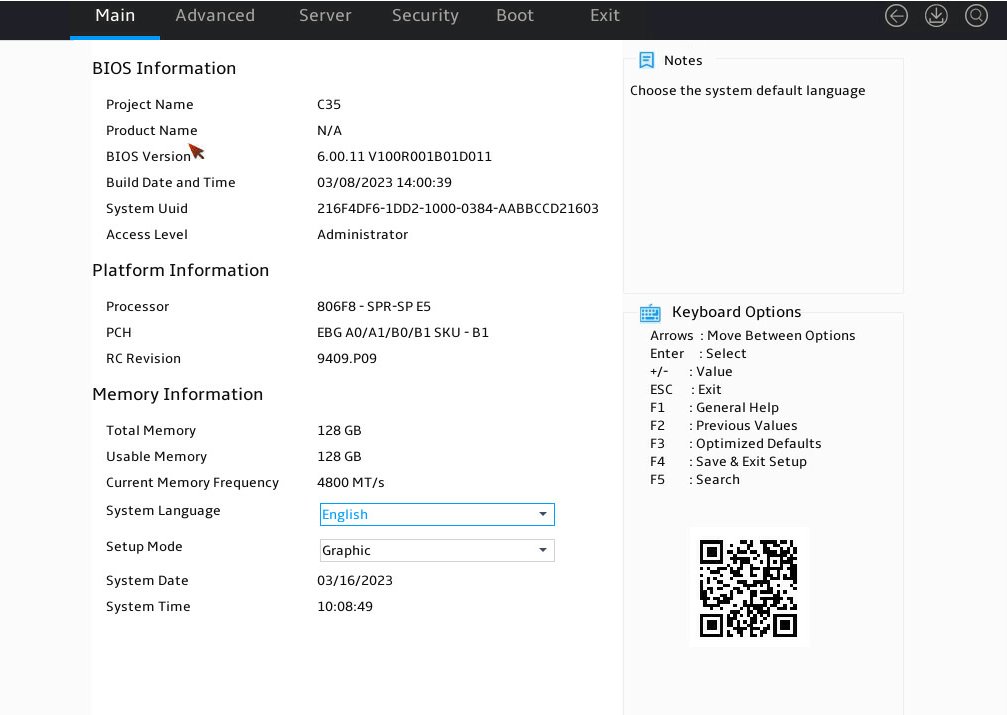
6. As shown in Figure 6, access the BIOS setup utility.
Accessing the Advanced Power Management Configuration screen
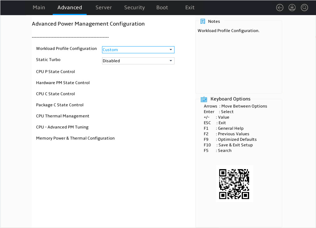
In the BIOS setup utility, click the Advanced tab, select Socket Configuration > Advanced Power Management Configuration, and press Enter, as shown in Figure 7.
Figure 7 Advanced Power Management Configuration menu
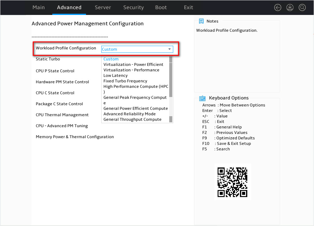
Selecting the configuration template
As shown in Figure 8, according to actual usage requirements, select the desired workload configuration template.
Figure 8 Selecting the configuration template
Restarting the system
After the setup, press F4 and select OK in the pop-up dialog box to save the settings and exit the BIOS interface. The setting will take effect after the server restarts.
