- Table of Contents
- Related Documents
-
| Title | Size | Download |
|---|---|---|
| 01-Text | 469.42 KB |
Removable components and compatibility matrixes
100/1000BASE-T management Ethernet port
100/1000BASE-T autosensing Ethernet port
100/1000BASE-T management Ethernet port LED
100/1000BASE-T autosensing Ethernet port LED
Port LED on an expansion module
1 Product overview
Product models
This document is applicable to the WX3800X series access controllers. Table1-1 describes the WX3800X series access controller models.
Table1-1 WX3800X series access controller models
|
Product series |
Product code |
Model |
Remarks |
|
WX3800X series |
EWP-WX3820X |
WX3820X |
Non-PoE models |
|
EWP-WX3840X |
WX3840X |
Technical specifications
Table1-2 Technical specifications
|
Item |
WX3820X |
WX3840X |
|
Dimensions (H × W × D) |
44 × 440 × 435 mm (1.73 × 17.32 × 17.13 in) |
|
|
Weight |
9 kg (19.84 lb) |
|
|
Console port |
1, control port, 9600 bps (default) to 115200 bps |
|
|
USB port |
2 (USB2.0) |
|
|
Management port |
1 × 100/1000BASE-T management Ethernet port |
|
|
SFP port |
8 × 1000BASE-X SFP ports |
|
|
100/1000BASE-T autosensing Ethernet port |
8 |
|
|
Reset button (RESET) |
· To restore the device to factory default settings, press and hold the button for more than 5 seconds. · To reset the device, press and hold the button for more than 15 milliseconds. |
|
|
Memory |
16GB DDR4 |
|
|
Storage media |
8GB eMMC memory |
|
|
Rated voltage range |
· PSR250-12A1-D: 100 to 240 VAC @ 50 or 60 Hz · PSR450-12D: –48 to –60 VDC |
|
|
System power consumption |
36 W to 107 W |
|
|
Operating temperature |
· Without drives: 0°C to 45°C (32°F to 113°F) · With drives: 5°C to 40°C (41°F to 104°F) |
|
|
Operating humidity |
· Without drives: 5% RH to 95% RH, noncondensing · With drives: 10% RH to 90% RH, noncondensing |
|
2 Chassis views
WX3820X&WX3840X
Front and rear views
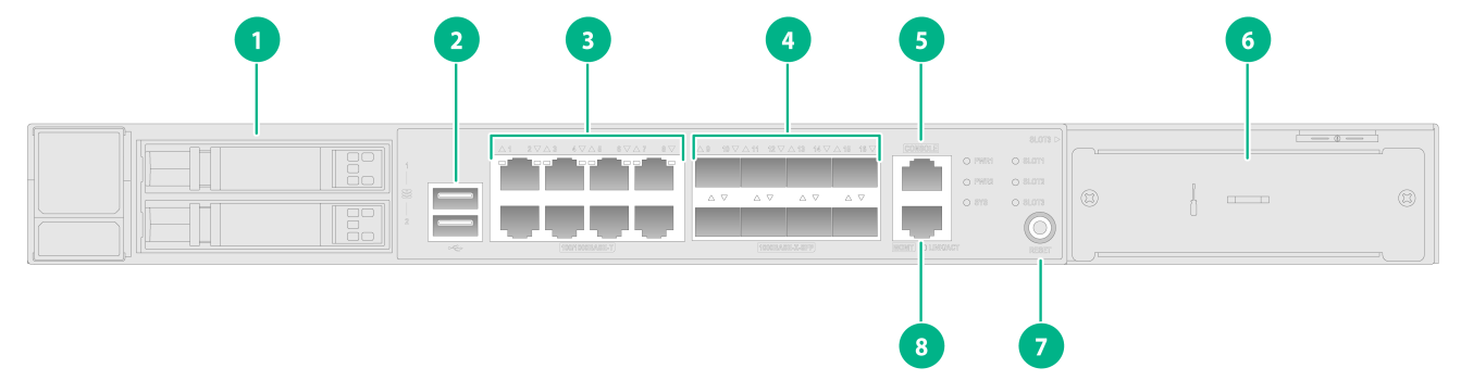
Figure2-1 Front view
|
(1) Drive slot |
(2) USB port |
|
(3) 100/1000BASE-T autosensing Ethernet ports 1 to 8 |
(4) 1000BASE-X SFP ports 9 to 16 |
|
(5) Console port |
(6) Expansion slot |
|
(7) Reset button (RESET) |
(8) 100/1000BASE-T out-of-band management Ethernet port |
|
|
IMPORTANT: If you use the console ports numbered 5 and 6 in the figure simultaneously, only the console port numbered 6 is activated. |
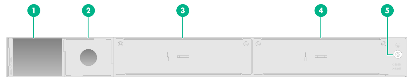
Figure2-2 Rear view
|
(1) Power supply slot PWR1 |
(2) Power supply slot PWR2 |
|
(3) MIM slot 1 |
(4) MIM slot 2 |
|
(5) Grounding screw |
|
LED locations
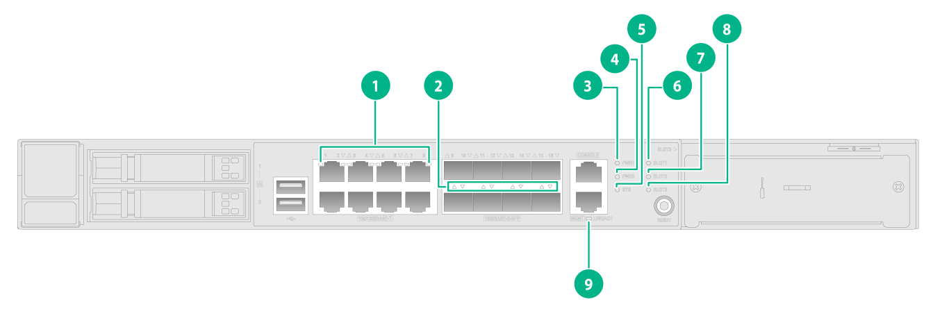
Figure2-3 Front panel LED locations
|
(1) 100/1000BASE-T autosensing Ethernet port LEDs |
(2) 1000BASE-X SFP port LEDs |
|
(3) Power supply status LED (PWR1) |
(4) Power supply status LED (PWR2) |
|
(5) System status LED (SYS) |
(6) Expansion module status LED (SLOT1) |
|
(7) Expansion module status LED (SLOT2) |
(8) Expansion module status LED (SLOT3) |
|
(9) 100/1000BASE-T out-of-band management Ethernet port status LED (LINK/ACT) |
|
3 Removable components
Removable components and compatibility matrixes
The access controllers use modular design. Table3-1 describes the compatibility matrix between access controllers and removable components.
Table3-1 Compatibility matrix between access controllers and removable components
|
Removable components |
WX3820X |
WX3840X |
|
Removable power supplies |
||
|
PSR250-12A1 |
Supported |
Supported |
|
PSR450-12D |
Supported |
Supported |
|
Expansion modules |
||
|
EWPM1WBCE0ENT |
Supported |
Supported |
|
EWPXM1XG03 |
Supported |
Supported |
|
EWPXM1XG20 |
N/A |
Supported |
|
Drives |
||
|
SSD-1.92T-SATA3-WCG |
Supported |
Supported |
Table3-2 describes the compatibility matrix between expansion modules and expansion slots.
Table3-2 Compatibility matrix between expansion modules and expansion slots
|
Expansion module |
WX3820X |
WX3840X |
||
|
Slot 1 Slot 2 |
Slot 3 |
Slot 1 Slot 2 |
Slot 3 |
|
|
EWPM1WBCE0ENT |
Supported |
N/A |
Supported |
N/A |
|
EWPXM1XG03 |
N/A |
Supported |
N/A |
Supported |
|
EWPXM1XG20 |
N/A |
N/A |
Supported |
N/A |
The power supplies support asset management. You can use display device manuinfo command to view the name, sequence number, and vendor of the power supply you have installed on the device.
Power supplies
|
|
WARNING! When the device has power supplies in redundancy, you can replace a power supply without powering off the device. To avoid device damage and bodily injury, make sure the power supply is powered off before you replace it. |
Table3-3 Power supply specifications
|
Power supply model |
Item |
Specification |
|
PSR250-12A1 |
Product code |
PSR250-12A1-D |
|
Rated AC input voltage range |
100 to 240 VAC @ 50 or 60 Hz |
|
|
Rated AC input current |
4 A |
|
|
Max AC input voltage range |
90 to 290 VAC @ 47 to 63 Hz |
|
|
Max AC input current |
5 A |
|
|
Output voltage |
12 V/3.3 V |
|
|
Output current |
20.9 A (12 V)/2 A (3.3 V) |
|
|
Max output power |
250 W |
|
|
Dimensions (H × W × D) |
40.2 × 50.5 × 221 mm (1.58 × 1.99 × 8.70 in) |
|
|
Operating temperature |
–10°C to +55°C (14°F to 131°F) |
|
|
Relative humidity |
5% RH to 95% RH, noncondensing |
|
|
PSR450-12D |
Product code |
PSR450-12D |
|
Rated DC input voltage range |
–48 to –60 VDC |
|
|
Rated DC input current |
12 A (48 VDC) 10 A (60 VDC) |
|
|
Max DC input voltage range |
–36 to –72 VDC |
|
|
Max DC input current |
15 A |
|
|
Output voltage |
12 V/3.3 V |
|
|
Output current |
37.5 A (12 V)/2 A (3.3 V) |
|
|
Max output power |
450 W |
|
|
Dimensions (H × W × D) |
40.2 × 50.5 × 221 mm (1.58 × 1.99 × 8.70 in) |
|
|
Operating temperature |
–10°C to +55°C (14°F to 131°F) |
|
|
Relative humidity |
5% RH to 95% RH, noncondensing |
Expansion modules
Table3-4 Expansion module specifications
|
Expansion module model |
Item |
Specification |
|
EWPM1WBCE0ENT |
Name |
Access controller module |
|
Port quantity and types |
· 2 × 100/1000BASE-T management Ethernet copper ports · 1 × console port · 2 × USB ports |
|
|
Port specifications |
· For detailed information about 100/1000BASE-T Ethernet copper ports, see Table4-8. · For detailed information about the console port, see Table4-1. · For detailed information about USB ports, see Table4-2. |
|
|
EWPXM1XG03 |
Name |
Interface expansion module |
|
Port quantity and types |
· 8 × 100/1000BASE-T Ethernet copper ports · 2 × SFP+ fiber ports |
|
|
Port specifications |
· For detailed information about 100/1000BASE-T Ethernet copper ports, see Table4-8. · For information about SFP+ modules and cables supported by the SFP+ fiber ports, see Table4-6. |
|
|
EWPXM1XG20 |
Name |
Interface expansion module |
|
Port quantity and types |
2 × 10G BASE-R-SFP+ fiber ports |
|
|
Port specifications |
For information about SFP+ modules and cables supported by the SFP+ fiber ports, see Table4-6. |
Drives
|
|
CAUTION: To avoid system anomalies, do not hot swap drives. |
No drives are provided with the device. Purchase them yourself as required.
Table3-5 Drive specifications
|
Drive model |
Item |
Specification |
|
SSD-1.92T-SATA3-WCG |
Capacity |
1.92 TB |
|
Port type |
SATA |
|
|
Port transmission rate |
6 Gbps |
|
|
Size |
SFF |
Cables
To avoid interference between cables, layer cables as follows:
· Do not bundle cables in their first 20 m (65.62 ft).
· Separate power cords and twisted pair cables at and around the distribution frame.
· For ports adjacent to one another on the device, the peer ports on the distribution frame are preferably not adjacent, for example:
¡ If the device connects to one distribution frame, connect port 1 on the device to port 1 on the distribution frame and port 2 on the device to port 3 on the distribution frame.
¡ If the device connects to two distribution frames, connect port 1 on the device to port 1 on distribution frame 1 and port 2 on the device to port 1 on distribution frame 2.
· Keep the device and cables away from the interference source, such as a two-way radio and a high-power variable-frequency drive.
4 Ports and LEDs
Ports
Console port
Table4-1 Console port specifications
|
Item |
Specification |
|
Connector type |
RJ-45 |
|
Compliant standard |
EIA/TIA-232 |
|
Port transmission rate |
9600 bps (default) to 115200 bps |
|
Services |
· Provides connection to an ASCII terminal · Provides connection to the serial port of a local PC running terminal emulation program |
|
Compatible devices |
All device models |
USB port
Table4-2 USB port specifications
|
Item |
Specification |
|
Port type |
USB 2.0 |
|
Compliant standard |
OHCI |
|
Port transmission rate |
Uploads and downloads data at a rate up to 480 Mbps |
|
Functions and services |
Accesses the file system on the flash of the device, for example, to upload or download application and configuration files |
|
Compatible devices |
All device models |
|
|
NOTE: USB devices from different vendors vary in compatibilities and drivers. H3C does not guarantee correct operation of USB devices from other vendors on the device. If a USB device fails to operate on the device, replace it with one from another vendor. |
SFP port
Table4-3 SFP port specifications
|
Item |
Specification |
|
Connector type |
LC |
|
Compatible transceiver modules |
GE SFP transceiver modules in Table4-4 |
|
Compatible devices |
All device models |
Table4-4 GE SFP transceiver modules
|
Transceiver module type |
Transceiver module model |
Central wavelength |
Receiver sensitivity |
Fiber diameter |
Data rate |
Max transmission distance |
|
GE multi-mode module |
SFP-GE-SX-MM850-A |
850 nm |
–17 dBm |
50 µm |
1.25 Gbps |
550 m (1804.46 ft) |
|
SFP-GE-SX-MM850-D |
850 nm |
–17 dBm |
50 µm |
1.25 Gbps |
550 m (1804.46 ft) |
|
|
GE single-mode module |
SFP-GE-LX-SM1310-A |
1310 nm |
–20 dBm |
9 µm |
1.25 Gbps |
10 km (6.21 miles) |
|
SFP-GE-LX-SM1310-D |
1310 nm |
–20 dBm |
9 µm |
1.25 Gbps |
10 km (6.21 miles) |
|
|
NOTE: · As a best practice, use H3C transceiver modules for the device. · The H3C transceiver modules are subject to change over time. For the most recent list of H3C transceiver modules, contact your H3C Support or marketing staff. · For more information about H3C transceiver modules, see H3C Transceiver Modules User Guide. |
SFP+ port
Table4-5 SFP+ port specifications
|
Item |
Specification |
|
Connector type |
LC |
|
Compatible transceiver modules and cables |
· GE SFP transceiver modules in Table4-4 · 10GE SFP+ transceiver modules and cables in Table4-6 |
|
Compatible devices |
Access controller installed with the EWPXM1XG03 or EWPXM1XG20 expansion module |
Table4-6 10GE SFP+ transceiver modules and cables
|
Transceiver module or cable type |
Transceiver module or cable model |
Central wavelength |
Receiver sensitivity |
Fiber diameter |
Data rate |
Max transmission distance |
|
10GE multi-mode module |
SFP-XG-SX-MM850-D |
850 nm |
–9.9 dBm |
50 µm |
10.31 Gbps |
300 m (984.25 ft) |
|
SFP-XG-SX-MM850-E |
850 nm |
–9.9 dBm |
50 µm |
10.31 Gbps |
300 m (984.25 ft) |
|
|
10GE single-mode module |
SFP-XG-LX-SM1310-D |
1310 nm |
–14.4 dBm |
9 µm |
10.31 Gbps |
10 km (6.21 miles) |
|
SFP-XG-LX-SM1310-E |
1310 nm |
–14.4 dBm |
9 µm |
10.31 Gbps |
10 km (6.21 miles) |
|
|
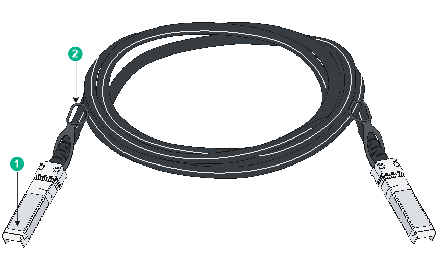
SFP+ cable |
LSWM3STK |
N/A |
N/A |
N/A |
N/A |
3 m (9.84 ft) |
Figure4-1 SFP+ cable
|
(1) Connector |
(2) Pull latch |
|
|
NOTE: · As a best practice, use H3C transceiver modules and cables for the device. · The H3C transceiver modules and cables are subject to change over time. For the most recent list of H3C transceiver modules and cables, contact your H3C Support or marketing staff. · For more information about H3C transceiver modules and cables, see H3C Transceiver Modules User Guide. |
100/1000BASE-T management Ethernet port
Table4-7 100/1000BASE-T management Ethernet port specifications
|
Item |
Specification |
|
Connector type |
RJ-45 |
|
Rate, duplex mode, and auto-MDI/MDI-X |
· 100 Mbps, half/full duplex · 1000 Mbps, full duplex · MDI/MDI-X autosensing |
|
Transmission medium |
Category 5 or above twisted pair cable |
|
Max transmission distance |
100 m (328.08 ft) |
|
Compliant standard |
IEEE 802.3i, 802.3u, 802.3ab |
|
Functions and services |
Device software and Boot ROM upgrade, network management |
|
Compatible devices |
All device models |
100/1000BASE-T autosensing Ethernet port
Table4-8 100/1000BASE-T autosensing Ethernet port specifications
|
Item |
Specification |
|
Connector type |
RJ-45 |
|
Rate, duplex mode, and auto-MDI/MDI-X |
· 100 Mbps, half/full duplex · 1000 Mbps, full duplex · MDI/MDI-X autosensing |
|
Max transmission distance |
100 m (328.08 ft) |
|
Transmission medium |
Category 5 or above twisted pair cable |
|
Compliant standard |
IEEE 802.3i, 802.3u, and 802.3ab |
|
Compatible devices |
All device models |
LEDs
System status LED
The system status LED shows the operating status of the device.
Table4-9 System status LED description
|
LED mark |
Status |
Description |
|
SYS |
Flashing green (4 Hz) |
The system is starting up. |
|
Flashing green (0.5 Hz) |
The system is operating correctly. |
|
|
Steady red |
A critical alarm has been triggered, for example, power supply alarm, fan tray alarm, high temperature alarm, and software loss. |
|
|
Off |
The device has not started up. |
SFP port LED
Table4-10 SFP port LED description
|
LED status |
Description |
|
Steady green |
A 1000 Mbps link is present on the port. |
|
Flashing green |
The port is receiving or sending data at 1000 Mbps. |
|
Off |
No link is present on the port. |
100/1000BASE-T management Ethernet port LED
Table4-11 100/1000BASE-T management Ethernet port LED description
|
LED mark |
Status |
Description |
|
LINK/ACT |
Steady green |
A link is present. |
|
Flashing green |
The port is receiving or sending data. |
|
|
Off |
No link is present. |
100/1000BASE-T autosensing Ethernet port LED
Table4-12 100/1000BASE-T autosensing Ethernet port LED description
|
LED status |
Description |
|
Steady yellow |
A 100 Mbps link is present on the port. |
|
Flashing yellow |
The port is receiving or sending data at 100 Mbps. |
|
Steady green |
A 1000 Mbps link is present on the port. |
|
Flashing green |
The port is receiving or sending data at 1000 Mbps. |
|
Off |
No link is present on the port. |
Power supply status LED
The device provides power supply status LEDs to indicate the operating status of power supplies.
Table4-13 Power supply status LED description
|
LED mark |
Status |
Description |
|
PWR1/PWR2 |
Steady green |
A power supply is installed in the power supply slot, and the power supply is operating correctly. |
|
Steady red |
A power supply is installed in the power supply slot, but the power supply has failed or is not operating. |
|
|
Off |
No power supply is installed in the power supply slot. |
Expansion module status LED
The device provides expansion module status LEDs to indicate the operating status of expansion modules.
Table4-14 Expansion module status LED description
|
LED mark |
Status |
Description |
|
SLOT1 to SLOT3 |
Steady green |
An expansion module is installed in the expansion slot, and the expansion module is operating correctly. |
|
Flashing red |
The device does not support the expansion module model, or the expansion module is faulty. |
|
|
Off |
No expansion module is installed in the expansion module slot. |
Status LED on a power supply
Table4-15 Description for the status LED on a power supply
|
LEDs status |
Description |
|
Steady green |
The power supply is operating correctly. |
|
Flashing green |
The power supply has power input but is not installed on the device. |
|
Steady red |
The power supply is faulty or has entered protection state. |
|
Red/green flashing alternatively |
The power supply has generated an alarm for power issues (such as output overcurrent, output overload, and overtemperature), but has not entered protection state. |
|
Flashing red |
· The power supply does not have power input. The device is installed with two power supplies. If one has power input, but the other does not, the status LED on the power supply that does not have power input flashes red. · The power supply has entered input undervoltage protection state. |
|
Off |
The power supply does not have power input. |
Port LED on an expansion module
Table4-16 Description for the port LEDs on an EWPM1WBCE0ENT
|
LED |
Status |
Description |
|
10GBASE-R-SFP+ fiber port LED |
Steady green |
The port is operating at 100/1000 Mbps, and a link is present on the port. |
|
Flashing green |
The port is receiving or sending data at 100/1000 Mbps. |
|
|
Off |
No transceiver module or cable has been installed or no link is present on the port. |
Table4-17 Description for the port LEDs on an EWPXM1XG03
|
LED |
Status |
Description |
|
100/1000BASE-T Ethernet copper port LED |
Steady green |
The port is operating at 1000 Mbps, and a link is present on the port. |
|
Flashing green |
The port is sending or receiving data at 1000 Mbps. |
|
|
Steady yellow |
The port is operating at 100 Mbps, and a link is present on the port. |
|
|
Flashing yellow |
The port is sending or receiving data at 100 Mbps. |
|
|
Off |
No transceiver module or cable has been installed or no link is present on the port. |
|
|
SFP+ fiber port LED |
Steady green |
The port is operating at 10 Gbps, and a link is present on the port. |
|
Flashing green |
The port is sending or receiving data at 10 Gbps. |
|
|
Steady yellow |
The port is operating at 1000 Mbps, and a link is present on the port. |
|
|
Flashing yellow |
The port is sending or receiving data at 1000 Mbps. |
|
|
Off |
No transceiver module or cable has been installed or no link is present on the port. |
Table4-18 Description for the port LEDs on an EWPXM1XG20
|
LED |
Status |
Description |
|
10GBASE-R-SFP+ fiber port LED |
Steady green |
The port is operating at 10 Gbps, and a link is present on the port. |
|
Flashing green |
The port is sending or receiving data at 10 Gbps. |
|
|
Off |
No transceiver module or cable has been installed or no link is present on the port. |
Drive status LED
The device provides drive status LEDs to indicate the operating status of drives.
Table4-19 Drive status LED description
|
LED status |
Description |
|
Steady green |
A drive is installed in the drive slot. |
|
Flashing green |
Data is being read from or written to the drive. |
|
Off |
No drive is installed in the drive slot. |
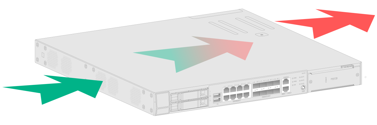
5 Cooling system
To dissipate heat timely and enhance system stability, the device uses a high-performance cooling system. Consider the site ventilation design when you plan the installation site for the device.
Table5-1 Cooling system
|
Product series |
Product model |
Airflow direction |
|
WX3800X series |
WX3820X |
The device provides airflow from the left side to the right side. See Figure5-1. |
|
WX3840X |
Figure5-1 Airflow from the left side to the right side through the device chassis