- Table of Contents
- Related Documents
-
| Title | Size | Download |
|---|---|---|
| 01-H3C High-Density WLAN Deployment Guide | 1.56 MB |
|
|
|
H3C High-Density WLAN |
|
Deployment Guide |
|
|
|
|
|
New H3C Technologies Co., Ltd. http://www.h3c.com
Document version: 6W100-20191125 |
Contents
About high density WLAN deployment
AP deployment and channel planning
Disabling APs from responding to broadcast probe requests
Conference and exhibition scenarios
Signal attenuation through materials
About high density WLAN deployment
Background
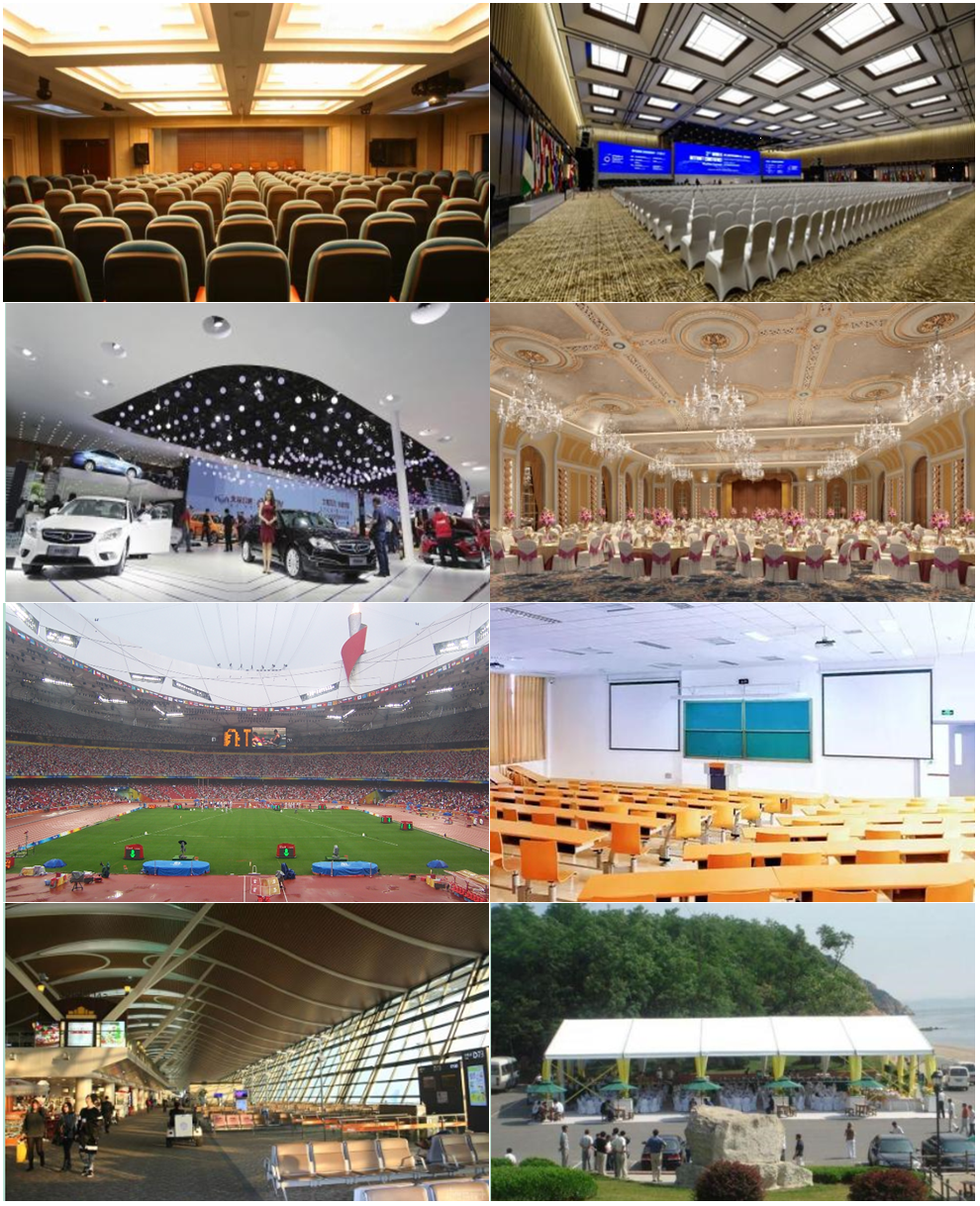
Public places such as large conference rooms and lecture halls require high-density and high-concurrency wireless access, which has the highest requirements on Wi-Fi performance among all WLAN deployment scenarios.
Such public places also include exhibition centers, banquet halls, stadiums, college classrooms, airport terminals, and temporary outdoor conference places.
H3C high-density WLAN deployment provides various WLAN optimization features to ensure optimal WLAN performance.
Figure 1 High-density WLAN access scenarios
Benefits
H3C high-density WLAN deployment offers the following benefits:
· High single-AP capacity provided by scenario-oriented APs.
· Flexible collaboration of various features, such as Layer 2 isolation, AP-based client quantity limit, AP-based client rate limit, and smart SSID hidden.
The number of clients that can access an AP depends on AP model, location, bandwidth, working mode, and bandwidth guarantee setting. For more information, contact the local sales agent.
Network structure
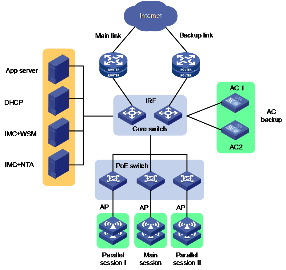
As shown in Figure 2, high-density deployment has the following requirements on the wired network:
· Two egress routers are deployed in dual-link backup mode to load balance each other.
· IRF is configured to virtualize the core switches and PoE switches are deployed at the access layer to supply power to APs through PoE.
· High-performance ACs are attached to the core switches in 1+1 backup mode to provide service redundancy.
· High-performance servers are deployed with the IMC WSM and NTA components to support backend data analysis.
Figure 2 High-density WLAN deployment
Deployment
Engineering survey
Prerequisites
· Identify the wireless coverage and its size, and obtain the layout of the coverage area, including obstacle distribution.
· Identify customers' coverage requirements, including client quantity and bandwidth requirements, and determine the transmission rate and AP quantity. The transmission rate will affect the coverage of each AP and the total AP quantity.
· Identify available device installation positions and installation methods.
· Identify available power supply methods and cabling methods.
· Identify the network structure of the existing wired network and egress resources.
· Identify the number and models of required network devices, accessories, and the accessory cost.
Site survey
· Perform the site survey together with property management staff of the covered area.
· Identify whether WLANs already exist and whether the existing WLANs can be disabled.
· As a best practice, bring a fat AP and use a client installed with the Wuwei app to test wireless coverage, signal attenuation, and channel usage, especially commonly used 2.4 GHz channels 1, 6, and 11. You can also use the cloud engineering survey feature provided by the Oasis platform to import or draw the layout of the site, set wall materials, and deploy APs of different models to simulate WLAN deployment.
· Most conference and exhibition halls require temporary WLAN setup with APs in the halls deployed under tables or seats and APs in other areas mounted on walls. To deploy a WLAN in such a site, communicate with the customers and site staff about the power supply, cabling, installation locations, and installation methods.
· Human bodies might affect signal transmission in crowded areas of a large conference or exhibition hall. If possible, perform an on-site test to assess the effect.
· Take security and anti-theft into consideration no matter whether the devices are provided, borrowed, or rent by the customers.
Survey summarization
After the site survey, sort out the determined installation positions, make a simulated heat map, and generate a site survey report for future deployment.
Deployment solution design
Before designing the deployment solution, communicate with the customers to identify their business demands, such as value-added applications, estimated user quantity, coverage, encryption, VIP user services, and session period. Then, analyze user characteristics, and provide initial networking, device selection, egress bandwidth, and application suggestions based on customers' demands. Make sure the suggestions meet availability, security, manageability, and expandability requirements.
Network structure design
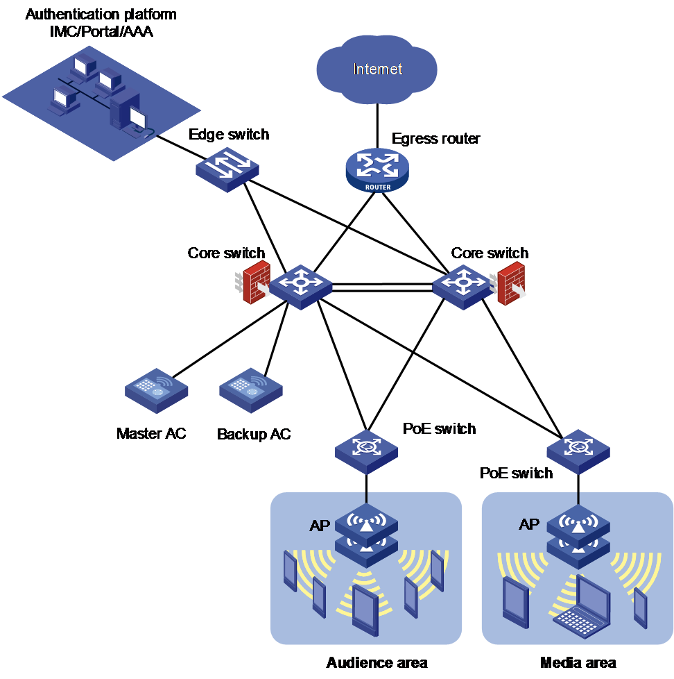
Figure 3 shows a high-density WLAN deployment solution for an exhibition hall.
· ACs are attached to the core switches and operate in dual-link backup mode.
· The authentication platform pushes different portals to clients based on the client type and user type.
· The core switches act as DHCP servers and provide NAT and firewall functions.
· The APs provide two SSIDs, one for audience access and the other for media access.
¡ Audiences can access limited resources.
¡ The media can access any resources through WPA+PSK encryption.
Figure 3 High-density WLAN deployment for an exhibition hall
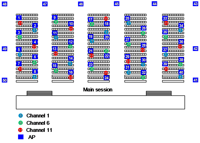
AP deployment and channel planning
When you deploy APs and plan channels, follow these restrictions and guidelines:
· Determine the AP models based on the physical structure of the installation site.
· Determine the AP quantity based on the client quantity. Typically, a dual-radio AP can support 60 clients and a triple-radio AP can support 100 clients.
· To minimize interference, plan channels, control the transmit power, and use obstacles and human bodies to reduce the cell size.
· If AP deployment positions are limited, take AP redundancy into consideration.
· Make sure the deployment can meet concurrent access of multiple users.
Figure 4, Figure 5, and Figure 6 show three AP deployment examples.
Figure 4 AP deployment example (1)
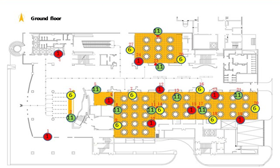
Figure 5 AP deployment example (2)
Deployment procedure
1. Finish basic configuration and the preparatory work, such as device classification and labelling.
2. Install devices as instructed in the blueprint. If any issue occurs, negotiate with the customers and site management staff to ensure that WLAN access requirements can be satisfied.
Update the blueprint if any changes are made, such as AP positions and quantity.
3. Finish public network egress configuration.
To leave enough time for test, finish the configuration two to three days before the exhibition or conference starts.
4. Prepare documents to deliver as required.
WLAN optimization
Channel planning
About this feature
To ensure the wireless coverage and signal strength, APs must be deployed at a certain density and signal overlapping is inevitable. If APs with overlapping coverage operate in the same channel, their signals will interfere with each other, affecting WLAN performance. To avoid inter-AP interference, you can configure these APs to operate in non-overlapping channels to create isolated WLANs, with each WLAN using the resources on a dedicated channel.
The 2.4 GHz band provides three non-overlapping channels: channels 1, 6, and 11.
To deploy WLANs on multiple floors, make sure every required area is covered both horizontally and vertically. Make sure devices deployed at neighboring floors do not interfere with each other.
|
|
NOTE: · As a best practice, set the bandwidth mode to 20 MHz for 802.11n radios in both 2.4 GHz and 5 GHz bands to enhance channel isolation and multiplexing and improve WLAN performance. · By default, the bandwidth mode is 80 MHz for 802.11ac radios and 40 MHz for 802.11an radios in the 5 GHz band for H3C APs. |
Command reference
channel
Use channel to specify a working channel for a radio.
Syntax
Views
Radio view
AP group radio view
Parameters
channel-number: Specifies a channel by its number. The value range for this argument varies by region code and radio mode.
Usage guidelines
Do not specify a radar channel.
The configuration in radio view takes precedence over the configuration in an AP group's radio view.
Examples
# Specify working channel 149 for AP ap1.
<Sysname> system-view
[Sysname] wlan ap ap1 model WA4320i-ACN
[Sysname-wlan-ap-ap1] radio 1
[Sysname-wlan-ap-ap1-radio-1] channel 149
# Specify working channel 149 for AP group apgroup1.
<Sysname> system-view
[Sysname] wlan ap-group apgroup1
[Sysname-wlan-ap-group-apgroup1] ap-model WA4320i-ACN
[Sysname-wlan-ap-group-apgroup1-ap-model-WA4320i-ACN] radio 1
[Sysname-wlan-ap-group-apgroup1-ap-model-WA4320i-ACN-radio-1] channel 149
channel band-width
Use channel band-width to set the bandwidth mode.
Syntax
channel band-width { 20 | 40 [ auto-switch ] | 80 | { 160 | dual-80 } [ secondary-channel channel-number ] }
Views
Radio view
AP group's radio view
Parameters
20: Sets the bandwidth mode to 20 MHz.
40: Sets the bandwidth mode to 40 MHz.
80: Sets the bandwidth mode to 80 MHz.
auto-switch: Allows a radio to switch its bandwidth mode between 20 MHz and 40 MHz. This keyword is applicable only to 802.11gn and 802.11gac radios.
160: Sets the bandwidth mode to 160 MHz. Support for this keyword depends on the AP model.
dual-80: Sets the bandwidth mode to 80+80 MHz. Support for this keyword depends on the AP model.
secondary-channel channel-number: Specifies the secondary channel for the 160 MHz or 80+80 MHz bandwidth mode. Support for this option depends on the AP model.
Usage guidelines
This command is applicable only to 802.11n, 802.11ac, and 802.11gac radios. When you change the mode of a radio, the default setting of this command for the new radio mode is restored.
The radio uses the specified 40/80/160 MHz bandwidth if adjacent channels can be bound to form a 40/80/160 channel. If adjacent channels cannot form a 40/80/160 channel, the radio uses the next available bandwidth less than the specified one.
For example, the bandwidth mode is set to 80 MHz. The radio uses the 80 MHz bandwidth if adjacent channels that can be bound together exist. If adjacent channels that can be bound to an 80 MHz channel do not exist, but two adjacent channels that can be bound to a 40 MHz channel exist, the 40 MHz bandwidth is used. If no adjacent channels that can be bound together exist, the radio uses the 20 MHz bandwidth.
When the bandwidth mode is set to 80+80 MHz, the radio uses the 160 MHz bandwidth if two adjacent 80 MHz channels that can be bound together exist. If a 160 MHz channel cannot be formed but two non-adjacent 80 MHz channels are available, the radio uses the two 80 MHz channels to achieve the 160 MHz bandwidth.
If the working channel is specified, you can specify the secondary 80 MHz channel for the 160 MHz or 80+80 MHz bandwidth mode. If no working channel is specified, the device automatically selects a secondary channel. The working channel forwards all packets and the secondary channel forwards only data packets.
The configuration in radio view takes precedence over the configuration in an AP group's radio view.
Examples
# Set the bandwidth mode to 40 MHz for AP ap1.
<Sysname> system-view
[Sysname] wlan ap ap1 model WA4320i-ACN
[Sysname-wlan-ap-ap1] radio 1
[Sysname-wlan-ap-ap1-radio-1] type dot11an
[Sysname-wlan-ap-ap1-radio-1] channel band-width 40
# Set the bandwidth mode to 40 MHz for AP group apgroup1.
<Sysname> system-view
[Sysname] wlan ap-group apgroup1
[Sysname-wlan-ap-group-apgroup1] ap-model WA4320i-ACN
[Sysname-wlan-ap-group-apgroup1-ap-model-WA4320i-ACN] radio 1
[Sysname-wlan-ap-group-apgroup1-ap-model-WA4320i-ACN-radio-1] type dot11an
[Sysname-wlan-ap-group-apgroup1-ap-model-WA4320i-ACN-radio-1] channel band-width 40
Transmit power optimization
About this feature
Perform this task to adjust the transmit power of each AP to reduce inter-AP interference, enhance channel resource multiplexing, and improve WLAN performance.
Command reference
max-power
Use max-power to set the maximum transmit power.
Syntax
max-power radio-power
Views
Radio view
AP group's radio view
Parameters
radio-power: Specifies the maximum transmit power.
Usage guidelines
The transmit power range supported by a radio varies by region code, channel, AP model, radio mode, antenna type, and bandwidth mode. If you change these attributes for a radio after you set the maximum transmit power, the configured maximum transmit power might be out of the supported transmit power range. If this happens, the system automatically adjusts the maximum transmit power to a valid value.
If you enable power lock, the locked power becomes the maximum transmit power.
As a best practice to avoid affecting user experience, do not enable auto TPC, because TPC might cause frequent client roaming.
The configuration in radio view takes precedence over the configuration in an AP group's radio view.
Examples
# Set the maximum transmit power to 15 dBm for AP ap1.
<Sysname> system-view
[Sysname] wlan ap ap1 model WA4320i-ACN
[Sysname-wlan-ap-ap1] radio 1
[Sysname-wlan-ap-ap1-radio-1] max-power 15
# Set the maximum transmit power to 15 dBm for AP group apgroup1.
<Sysname> system-view
[Sysname] wlan ap-group apgroup1
[Sysname-wlan-ap-group-apgroup1] ap-model WA4320i-ACN
[Sysname-wlan-ap-group-apgroup1-ap-model-WA4320i-ACN] radio 1
[Sysname-wlan-ap-group-apgroup1-ap-model-WA4320i-ACN-radio-1] max-power 15
Layer 2 isolation
About this feature
In a VLAN, broadcast and multicast packets from a client are transmitted to all APs that permit the client VLAN at a low rate. If a large number of such packets exist, channel usage gets high, which affects network performance. To resolve the issue, you can enable Layer 2 isolation to allow clients to access only the gateway.
To further reduce multicast and broadcast packets, you can execute the undo user-isolation permit-broadcast command to forbid wired terminals from sending non-unicast packets to wireless clients. Wired terminals permitted by using the user-isolation vlan permit-mac command are not affected.
|
|
NOTE: To configure user isolation at Layer 2 in a local forwarding network, you must use a MAP file to deploy the configuration to APs. |
Command reference
user-isolation vlan enable
Use user-isolation vlan enable to enable user isolation for a list of VLANs.
Syntax
user-isolation vlan vlan-list enable [ permit-unicast ]
Views
System view
Parameters
vlan-list: Specifies a space-separated list of up to 10 VLAN items. Each VLAN item specifies a VLAN by VLAN ID or specifies a range of VLANs in the form of vlan-id1 to vlan-id2. The value range for the VLAN IDs is 1 to 4094. If you specify a VLAN range, the value for the vlan-id2 argument must be greater than the value for the vlan-id1 argument.
permit-unicast: Permits unicast packets among users. If you do not specify this keyword, unicast packets are isolated among users together with broadcast and multicast packets.
Usage guidelines
To avoid network disconnection to the external network, add the MAC address of the gateway to the permitted MAC address list. To add a permitted MAC address, use the user-isolation vlan permit-mac command.
If you execute the user-isolation vlan enable command multiple times, the device accumulates the specified VLANs. If you execute the user-isolation vlan enable command multiple times for a VLAN, the most recent configuration takes effect.
Examples
# Enable user isolation for VLAN 1.
<Sysname> system-view
[Sysname] user-isolation vlan 1 enable
user-isolation vlan permit-mac
Use user-isolation vlan permit-mac to configure the permitted MAC address list for a list of VLANs.
Syntax
user-isolation vlan vlan-list permit-mac mac-list
Views
System view
Parameters
vlan-list: Specifies a space-separated list of up to 10 VLAN items. Each VLAN item specifies a VLAN by VLAN ID or specifies a range of VLANs in the form of vlan-id1 to vlan-id2. The value range for the VLAN IDs is 1 to 4094. If you specify a VLAN range, the value for the vlan-id2 argument must be greater than the value for the vlan-id1 argument.
mac-list: Specifies a space-separated list of up to 16 MAC addresses. Each MAC address is in the form of H-H-H. The MAC addresses cannot be broadcast or multicast MAC addresses.
Usage guidelines
Packets from users of the permitted MAC addresses are not isolated in their corresponding VLANs.
If you execute the user-isolation vlan permit-mac command multiple times, the device accumulates the specified permitted MAC addresses. The number of permitted MAC addresses cannot exceed 64 for a VLAN.
Examples
# Specify permitted MAC addresses 00bb-ccdd-eeff and 0022-3344-5566 for VLAN 1.
<Sysname> system-view
[Sysname] user-isolation vlan 1 permit-mac 00bb-ccdd-eeff 0022-3344-5566
user-isolation permit-broadcast
Use undo user-isolation permit-broadcast to forbid broadcast and multicast traffic sent from wired users to wireless users.
Syntax
undo user-isolation permit-broadcast
Views
System view
Usage guidelines
Isolate broadcast and multicast packets of wired users from wireless users only in the following situations:
· The wired and wireless users belong to the same VLAN.
· The AC that the users access is an IRF fabric.
Examples
# Forbid broadcast and multicast traffic sent from wired users to wireless users.
<Sysname> system-view
[Sysname] undo user-isolation permit-broadcast
Low rates prohibition
About this feature
In a WLAN, clients and APs randomly select a rate from the rate set defined by the radio type to send traffic. For example, 802.11g radios can use rates 1, 2, 5.5, 11, 6, 9, 12, 18, 24, 36, 48, and 54 Mbps. Multicast and broadcast packets are always transmitted at the lowest rate (1 Mbps) and consume a lot of channel resources.
If long-distance transmission is not required, you can prohibit low rates such as 1, 2, 6, and 9 Mbps to improve channel efficiency.
Prohibiting low rates might cause packet loss on weak-signal clients far from the APs. In indoor wireless deployment, prohibiting low rates is required.
Command reference
rate disabled
Use rate disabled to forbid low rates.
Syntax
rate disabled rate-value
Views
Radio view
AP group's radio view
Parameters
disabled: Specifies the prohibited rates.
rate-value: Specifies the rate value in Mbps. You can set multiple rates and separate them by spaces. The available values for this argument are as follows:
· 802.11a/802.11an/802.11ac—6, 9, 12, 18, 24, 36, 48, and 54.
· 802.11b—1, 2, 5.5, and 11.
· 802.11g/802.11gn/802.11gac—1, 2, 5.5, 6, 9, 11, 12, 18, 24, 36, 48, and 54.
Usage guidelines
The configuration in radio view takes precedence over the configuration in an AP group's radio view.
Examples
# Forbid rates 1, 2, 5.5, 6, and 9 Mbps for the 802.11g radio of AP ap1.
<Sysname> system-view
[Sysname] wlan ap ap1 model WA4320i-ACN
[Sysname-wlan-ap-ap1] radio 2
[Sysname-wlan-ap-ap1-radio-2] rate disabled 1 2 5.5 6 9
# Forbid rates 1, 2, 5.5, 6, and 9 Mbps for the 802.11g radio of WA4320i-ACN APs in AP group apgroup1.
<Sysname> system-view
[Sysname] wlan ap-group apgroup1
[Sysname-wlan-ap-group-apgroup1] ap-model WA4320i-ACN
[Sysname-wlan-ap-group-apgroup1-ap-model-WA4320i-ACN] radio 2
[Sysname-wlan-ap-group-apgroup1-ap-model-WA4320i-ACN-radio-2] rate disabled 1 2 5.5 6 9
Client rate limiting
About this feature
In a WLAN, all clients share the total bandwidth. If a client uses a tool to download files, it might consume a large amount of bandwidth resources and cause long latency and packet loss of other clients. You can configure client rate limiting to prevent aggressive use of bandwidth by one client and ensure fair use of bandwidth among clients associated with the same AP.
You can configure either of the following modes for client rate limiting:
· Dynamic mode—Sets the total bandwidth shared by all clients.
· Static mode—Sets the bandwidth that can be used by each client.
|
|
NOTE: Do not configure both client rate limiting and bandwidth guaranteeing. |
Command reference
client-rate-limit
Use client-rate-limit to configure radio-based client rate limiting.
Syntax
client-rate-limit { inbound | outbound } mode { dynamic | static } cir cir
Views
Radio view
AP group's radio view
Parameters
inbound: Limits the rate of incoming traffic.
outbound: Limits the rate of outgoing traffic.
dynamic: Specifies the dynamic rate limit mode. In this mode, the maximum rate for each client is the total maximum rate divided by the number of clients.
static: Specifies the static rate limit mode. The maximum rate for each client is fixed.
cir cir: Specifies the CIR in Kbps. The value range for the cir argument is 16 to 1700000. This option sets the maximum rate for each client in static rate limit mode and sets the total maximum rate for all clients in dynamic rate limit mode.
Usage guidelines
For this command to take effect, make sure radio-based client rate limiting is enabled.
You can repeat this command multiple times to limit the rates of both the incoming and outgoing traffic.
The configuration in radio view takes precedence over the configuration in an AP group's radio view.
Examples
# Configure client rate limiting for radio 1 in radio view: set the CIR to 567 Kbps for incoming traffic of each client and set the CIR to 89 Kbps for outgoing traffic of all clients.
<Sysname> system-view
[Sysname] wlan ap ap1 model WA4320i-ACN
[Sysname-wlan-ap-ap1] radio 1
[Sysname-wlan-ap-ap1-1] client-rate-limit enable
[Sysname-wlan-ap-ap1-1] client-rate-limit inbound mode static cir 567
[Sysname-wlan-ap-ap1-1] client-rate-limit outbound mode dynamic cir 89
# Configure client rate limiting for radio 1 in an AP group's radio view: set the CIR to 567 Kbps for incoming traffic of each client and set the CIR to 89 Kbps for outgoing traffic of all clients.
<Sysname> system-view
[Sysname] wlan ap-group apgroup1
[Sysname-wlan-ap-group-apgroup1] ap-model WA4320i-ACN
[Sysname-wlan-ap-group-apgroup1-ap-model-WA4320i-ACN] radio 1
[Sysname-wlan-ap-group-apgroup1-ap-model-WA4320i-ACN-radio-1] client-rate-limit enable
[Sysname-wlan-ap-group-apgroup1-ap-model-WA4320i-ACN-radio-1] client-rate-limit inbound mode static cir 567
[Sysname-wlan-ap-group-apgroup1-ap-model-WA4320i-ACN-radio-1] client-rate-limit outbound mode dynamic cir 89
Disabling APs from responding to broadcast probe requests
About this task
Broadcast probe requests do not carry any SSIDs. Upon receiving a broadcast probe request, an AP responds with a probe response that carries service information for the AP at a low rate. If a large number of probe responses are transmitted, channel usage might be high, affecting traffic transmission and WLAN performance.
To resolve this issue, you can disable APs from responding to broadcast probe requests.
Command reference
broadcast-probe reply disable
Use broadcast-probe reply disable to disable an AP from responding to broadcast probe requests.
Syntax
broadcast-probe reply disable
Views
AP view
AP group view
Usage guidelines
Broadcast probe requests do not carry any SSIDs. Upon receiving a broadcast probe request, an AP responds with a probe response that carries service information for the AP at a low rate. If a large number of probe responses are transmitted, channel usage might be high, affecting traffic transmission and WLAN performance.
The configuration in AP view takes precedence over the configuration in AP group view.
Examples
# Disable AP ap1 from responding to broadcast probe requests.
<AC> system-view
[AC] wlan ap ap1 model WA4320i-ACN
[AC-wlan-ap-ap1] broadcast-probe reply disable
# Disable APs in AP group group1 from responding to broadcast probe requests.
<AC> system-view
[AC] wlan ap-group group1
[AC-wlan-ap-group-group1] broadcast-probe reply disable
Rejecting weak-signal clients
About this task
This feature enables an AP to reject clients with an RSSI lower than the specified threshold to release channel resources and enhance WLAN performance.
After you enable this feature, wireless clients with an RSSI lower than the threshold might fail to access the WLAN.
Command reference
option client reject
Use option client reject enable to enable an AP to reject weak-signal clients.
Use option client reject disable to disable an AP from rejecting weak-signal clients.
Syntax
option client reject { disable | enable [ rssi rssi-value ] }
Views
Radio view
AP group's radio view
Parameters
rssi rssi-value: Specifies the RSSI threshold in the range of 5 to 100. Both the default and recommended RSSI thresholds are 10.
Usage guidelines
This feature enables an AP to reject clients with an RSSI lower than the specified threshold to release channel resources and enhance WLAN performance.
Examples
# Enable AP ap1 to reject clients with an RSSI lower than 10 dBm.
<AC> system-view
[AC] wlan ap ap1 model WA4320i-ACN
[AC-wlan-ap-ap1] radio 1
[AC-wlan-ap-ap1-radio-1] option client reject enable rssi 10
# Enable APs with model WA4320i-ACN in AP group 1 to reject clients with an RSSI lower than 10 dBm.
<AC> system-view
[AC] wlan ap-group 1
[AC-wlan-ap-group-1] ap-model WA4320i-ACN
[AC-wlan-ap-group-1-ap-model-WA4320i-ACN] radio 1
[AC-wlan-ap-group-1-ap-model-WA4320i-ACN-radio-1] option client reject enable rssi 10
Typical application scenarios
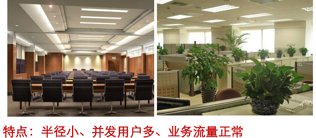
Co-working offices
A co-working office, such as an open office or cubicles, has the following features:
· Small in size.
· Large number of concurrent users.
· Normal service traffic.
· High requirements on device appearance and antenna hiding.
· Unified wired and wireless access.
To deploy a WLAN in a co-working space, follow these restrictions and guidelines:
· Make full use of obstacles, such as pillars and glass walls, to reduce inter-AP interference and maximize wireless coverage.
· Make sure the ceiling material will not greatly attenuate the strength of wireless signals if you deploy APs over the ceiling, and install ceiling-mounted antennas if necessary to ensure wireless performance.
· If frequent client roaming is required, configure WLAN optimization to ensure seamless and smooth client roaming.
Figure 6 Co-working offices
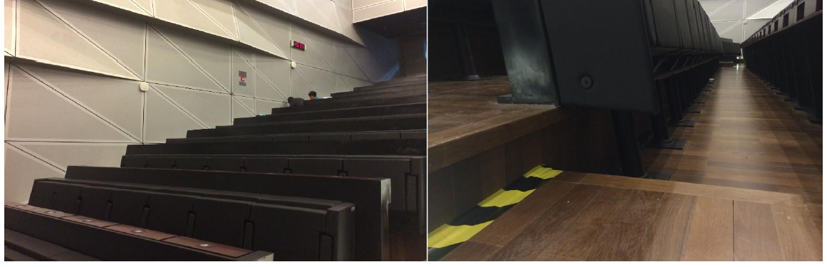
Conference rooms
When you deploy a WLAN in a conference room, follow these restrictions and guidelines:
· You can install APs over the ceiling in a small- to medium-sized conference room that can accommodate 200 or fewer participants.
For a large conference room that can accommodate over 300 participants, see the PowerPoint presentation for high-density Wi-Fi deployment in conference rooms.
· You can use both wall mounting and ceil mounting in lecture halls.
· If available, install APs below chairs as a best practice to use human bodies to shrink the cell size and reduce inter-AP interference.
Figure 7 Conference rooms
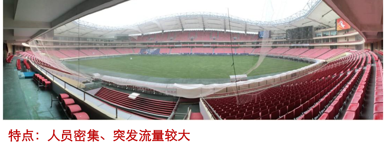
Stadiums
Stadiums have the following features:
· Tiered seating.
· High roof.
· High-density mobile access (mainly cellphones) and large concurrent traffic.
· Large burst traffic (during activity intervals) but low requirements on per-client bandwidth (mainly used for social media access).
· Outdoor deployment, which requires weather-proof and security measures.
To deploy a WLAN in a stadium, follow these restrictions and guidelines:
· Install dual-band APs and directional antennas to provide wireless coverage for the tiered seating area.
· Control the coverage of each AP to reduce inter-AP interference, and increase AP quantity to meet concurrent access demands.
· Take antenna horizontal and vertical lobe angles into consideration and adjust the coverage of the main lobe.
· Reserve installation positions as needed for temporary AP extension in case of special activities.
· In indoor venues, install indoor APs with smart antennas, use the wall mounting method, and install directional antennas as needed to enhance signal strength.
· In indoor venues, you can install APs under seats and take anti-theft measures.
Figure 8 Stadiums
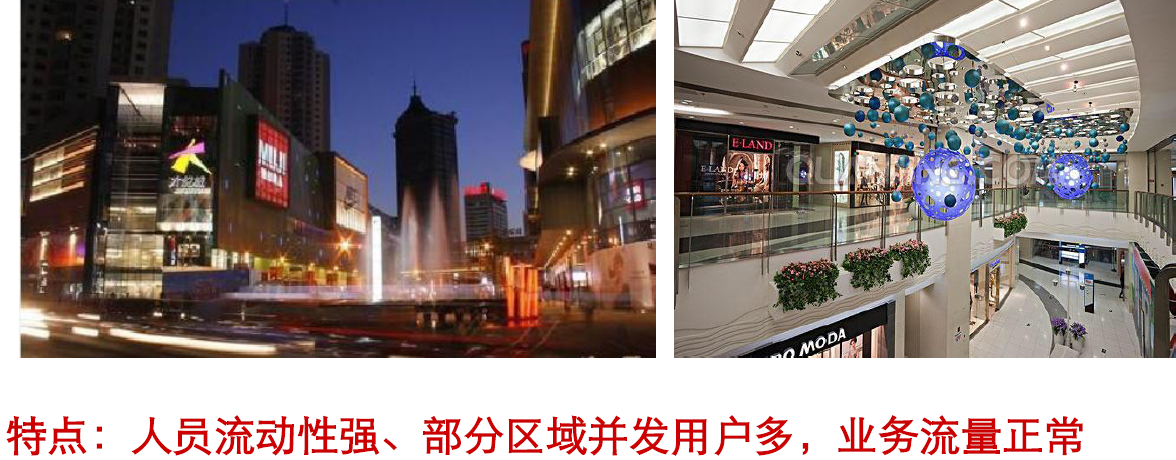
Shopping malls
Shopping malls have the following features:
· Strong personnel mobility.
· Concentrated users and traffic in rest areas and activity areas.
· Short-period burst traffic and high-density access during commercial activities.
When you deploy a WLAN in a shopping mall, follow these restrictions and guidelines:
· Make sure a client can be detected by multiple APs at the same time to ensure mobility performance. As a best practice, attach rod antennas to APs.
· Coffee shops might have Wi-Fi hotspots. You can consult in advance during the engineering survey and avoid this area during AP deployment.
· Avoid using directional antennas radiating downward from very high positions in an atrium because the wireless experience might decrease due to insufficient terminal signal return and APs in other areas might be affected.
· You can install APs in advertising light boxes or behind plants.
Figure 9 Shopping malls
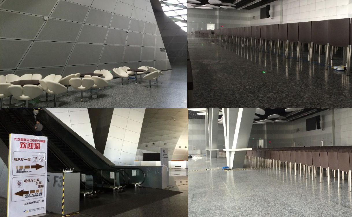
Conference and exhibition scenarios
The conference scenario always involves multiple areas, such as the main session area, parallel session areas, hallways, the attendance area, and the tea break area, and an exhibition might require both indoor and outdoor deployments.
When you deploy a WLAN for a conference or exhibition, follow these restrictions and guidelines:
· The venue might have pre-existing WLANs. You need to communicate with the customers about whether they want to use the existing WLAN or deploy a temporary WLAN.
· Consider future service expansion.
· Identify the number of APs based on the estimated client quantity (50 clients for each AP).
Figure 10 Conference and exhibition scenarios
Appendix
Signal attenuation through materials
|
Material |
Attenuation degree |
Attenuation (dB) |
Examples |
|
Open ground |
Very low |
N/A |
Cafeteria and courtyard |
|
Wood |
Low |
3 to 5 |
Interior wall, partition wall, door, and floor |
|
Plaster |
Low |
5 to 8 |
Interior wall |
|
Synthetic material |
Low |
5 to 8 |
Partition wall |
|
Asbestos cinder |
Low |
5 to 8 |
Interior wall and exterior wall |
|
Asbestos |
Low |
5 to 8 |
Ceiling |
|
Glass |
Low |
5 to 8 |
Colorless window |
|
Human body |
Moderate |
10 to 15 |
Crowd of people |
|
Water |
Moderate |
10 to 15 |
Damp wood, glass vat, and organism |
|
Brick |
Moderate |
10 to 15 |
Interior wall, exterior wall, and floor |
|
Marble |
Moderate |
15 to 20 |
Interior wall, exterior wall, and floor |
|
Ceramic |
High |
20 to 25 |
Ceramic tile, ceiling, and floor |
|
Paper |
High |
20 to 25 |
Box or pile of papers |
|
Concrete |
High |
20 to 25 |
Floor, exterior wall, and load-bearing beam |
|
Bullet-proof glass |
High |
20 to 25 |
Safe tent |
|
Silver plating |
Very high |
25 to 30 |
Mirror |
|
Metal |
Very high |
25 to 30 |
Partition wall, concrete, elevator |
Radar channels
Channels 52, 56, 60, 64, 100, 104, 108, 112, 116, 120, 124, 128, 132, 136, 140, and 144 can be used to transmit radar signals. As a best practice, do not specify a radar channel for an AP. If an AP detects radar signals on its working channel, it changes its working channel or stops transmission as configured.
If you must use such a channel, identify the radar source and non-WLAN interference source, and remove the sources to ensure WLAN performance.
