- Table of Contents
- Related Documents
-
| Title | Size | Download |
|---|---|---|
| 01-H3C WLAN Products Optimization Guide | 220.60 KB |
|
H3C WLAN Products Optimization Guide |
|
|
|
New H3C Technologies Co., Ltd. http://www.h3c.com
Document version: 6W101-20230331
|
Required operation: Deploying APs and antennas properly to ensure the signal strength
About wireless signal strength
Required operation: Planning channels and configuring channel locking
Required operation: Planning the transmit power and configuring power locking
Required operation: Using a separate VLAN for a WLAN service
About using a separate VLAN for a WLAN service
Required operation: Configuring VLAN-based user isolation
About VLAN-based user isolation
user-isolation vlan permit-mac
user-isolation permit-broadcast
Recommended operation: Setting the VLAN allocation method to static for clients
About VLAN allocation for clients
Recommended operation: Specifying prohibited rates
Recommended operation: Configuring client rate limiting
Recommended operation: Configuring port isolation for the downlink wired port on a WTU
Recommended operation: Setting an idle timeout period for portal users
Optional operation: Configuring frame encryption
Optional operation: Configuring rejection of weak-signal clients
About rejection of weak-signal clients
Required operation: Assigning the wired interfaces on the AC to only necessary VLANs
Required operation: Stability of the wired link between the AC and an AP
Required operation: Configuring an independent VLAN for the IRF link
About configuring an independent VLAN for the IRF link
Required operation: Disabling STP for interfaces that connect the switch to the IRF port on the AC
About disabling STP for interfaces that connect the switch to the IRF ports
Required operation: Deploying APs and antennas properly to ensure the signal strength
About wireless signal strength
Sufficient signal strength (over –65 dBm) is required for correct transmission in the wireless coverage. For high-power APs with over 500 mW power, you must also monitor the RSSI detected by the APs to ensure that both the uplink and downlink signals can meet the transmission requirement. Signals with a RSSI higher than 30 are considered strong and signals with a RSSI lower than 20 are considered weak.
<AC>display wlan client verbose
Total number of clients: 64
MAC address : 0cd6-bd00-a98e
IPv4 address : N/A
……
RSSI : 40
Rx/Tx rate : 72.2/72.2
Guidelines
Deploy APs or antennas close to the target area and make sure no obstacles that might weaken the wireless signal strength exist, such as a metal board or thick wall.
For room-corridor scenarios, such as in a dormitory or academic building, do not deploy APs in the corridor as a best practice. If you deploy APs in the corridor, the following issues might occur:
· Weak signals in rooms that cannot meet the client access requirement.
· Too many overlapping coverage areas and strong interference.
For high-density access scenarios, such as in a classroom or conference room, deploy APs in the rooms as a best practice. For room-corridor scenarios, such as in a dormitory building, hotel, or apartment building, use low-cost deployment methods as a best practice, such as X-share or walljack AP deployment.
Required operation: Planning channels and configuring channel locking
About channel planning
Channel planning and power adjustment are the primary WLAN optimization methods.
In actual deployment, to ensure signal strength in the wireless coverage, multiple APs must be deployed in an area, which might cause overlapping coverage areas. If the adjacent APs work on the same channel, co-channel interference occur, affecting the transmission performance.
WLAN protocols provide sets of non-overlapping channels to form isolated virtual WLANs in the same area for adjacent radios to use different channels. For example, for 2.4GHz radios, you can use non-overlapping channels 1, 6, and 11.
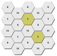
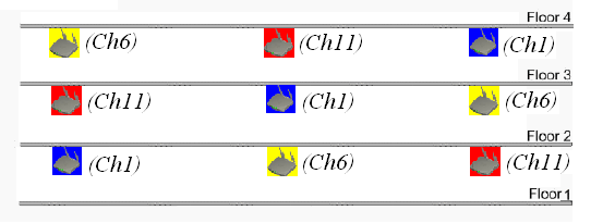
When planning channels, take both horizontal and vertical deployment into consideration. Make sure that cellular coverage is provided and co-channel interference is avoided on the same floor and between adjacent floors.
|
|
NOTE: · In an 802.11n WLAN, use the 20 MHz bandwidth mode as a best practice for both 2.4 GHz and 5 GHz radios to improve channel reuse and isolation. · By default, H3C APs use the 80 MHz bandwidth mode for 802.11ax and 802.11ac radios and 40MHz bandwidth mode for 802.11an radios on the 5GHz band, respectively. |
Figure 1 Channel planning
Command reference
channel
Use channel to specify the working channel for a radio.
Syntax
Parameters
channel-number: Specifies a channel by its number. The value range for this argument varies by region code and radio mode.
Usage guidelines
Do not specify a radar channel as the working channel.
The configuration in radio view takes precedence over the configuration in an AP group's radio view.
Examples
# Specify working channel 149 for radio 1 of AP ap1.
<Sysname> system-view
[Sysname] wlan ap ap1 model WA6320
[Sysname-wlan-ap-ap1] radio 1
[Sysname-wlan-ap-ap1-radio-1] channel 149
# Specify working channel 149 for radio 1 of APs with model WA6320 in AP group apgroup1.
<Sysname> system-view
[Sysname] wlan ap-group apgroup1
[Sysname-wlan-ap-group-apgroup1] ap-model WA6320
[Sysname-wlan-ap-group-apgroup1-ap-model-WA6320] radio 1
[Sysname-wlan-ap-group-apgroup1-ap-model-WA6320-radio-1] channel 149
channel band-width
Use channel band-width to set the bandwidth mode.
Syntax
channel band-width { 20 | 40 [ auto-switch ] | 80 | { 160 | dual-80 } [ secondary-channel channel-number ] }
Parameters
20: Sets the bandwidth mode to 20 MHz.
40: Sets the bandwidth mode to 40 MHz.
80: Sets the bandwidth mode to 80 MHz.
auto-switch: Allows a radio to switch its bandwidth mode between 20 MHz and 40 MHz. This keyword is applicable only to 802.11gn and 802.11gac radios.
160: Sets the bandwidth mode to 160 MHz. Support for this keyword depends on the AP model.
dual-80: Sets the bandwidth mode to 80+80 MHz. Support for this keyword depends on the AP model.
secondary-channel channel-number: Specifies the secondary channel for the 160 MHz or 80+80 MHz bandwidth mode. Support for this option depends on the AP model.
Usage guidelines
This command is applicable only to 802.11n, 802.11ac, 802.11gac, 802.11ax, and 802.11gax radios. When you change the mode of a radio, the default setting of this command for the new radio mode is restored.
The radio uses the specified 40/80/160 MHz bandwidth if adjacent channels can be bound to form a 40/80/160 channel. If adjacent channels cannot form a 40/80/160 channel, the radio uses the next available bandwidth less than the specified one.
For example, the bandwidth mode is set to 80 MHz. The radio uses the 80 MHz bandwidth if adjacent channels that can be bound together exist. If adjacent channels that can be bound to an 80 MHz channel do not exist, but two adjacent channels that can be bound to a 40 MHz channel exist, the 40 MHz bandwidth is used. If no adjacent channels that can be bound together exist, the radio uses the 20 MHz bandwidth.
When the bandwidth mode is set to 80+80 MHz, the radio uses the 160 MHz bandwidth if two adjacent 80 MHz channels that can be bound together exist. If a 160 MHz channel cannot be formed but two non-adjacent 80 MHz channels are available, the radio uses the two 80 MHz channels to achieve the 160 MHz bandwidth.
If the working channel is specified, you can specify the secondary 80 MHz channel for the 160 MHz or 80+80 MHz bandwidth mode. If no working channel is specified, the device automatically selects a secondary channel. The working channel forwards all packets and the secondary channel forwards only data packets.
The configuration in radio view takes precedence over the configuration in an AP group's radio view.
Examples
# Set the bandwidth mode to 40 MHz for radio 1 of AP ap1.
<Sysname> system-view
[Sysname] wlan ap ap1 model WA6320
[Sysname-wlan-ap-ap1] radio 1
[Sysname-wlan-ap-ap1-radio-1] type dot11an
[Sysname-wlan-ap-ap1-radio-1] channel band-width 40
# Set the bandwidth mode to 40 MHz for radio 1 of APs with model WA6320 in AP group apgroup1.
<Sysname> system-view
[Sysname] wlan ap-group apgroup1
[Sysname-wlan-ap-group-apgroup1] ap-model WA6320
[Sysname-wlan-ap-group-apgroup1-ap-model-WA6320] radio 1
[Sysname-wlan-ap-group-apgroup1-ap-model-WA6320-radio-1] type dot11an
[Sysname-wlan-ap-group-apgroup1-ap-model-WA6320-radio-1] channel band-width 40
Required operation: Planning the transmit power and configuring power locking
About transmit power planning
Transmit power affects the signal strength of a wireless device. A higher transmit power enables a radio to cover a larger area but it brings more interference to adjacent devices. The signal strength decreases as the transmission distance increases.
After channel planning, adjust the transmit power of adjacent radios working on the same channel to reduce visibility between the APs and enhance the reuse of spectrum resources to improve the overall WLAN performance.
Command reference
max-power
Use max-power to set the maximum transmit power.
Syntax
max-power radio-power
Parameters
radio-power: Specifies the maximum transmit power.
Usage guidelines
|
|
NOTE: As a best practice, do not configure transmit power control (TPC). Dynamic transmit power adjustment triggered by TPC might cause frequent client roaming and affect user experience. |
The transmit power range supported by a radio varies by region code, channel, AP model, radio mode, antenna type, and bandwidth mode. If you change these attributes for a radio after setting the maximum transmit power, the configured maximum transmit power might be out of the supported transmit power range. If this happens, the system automatically adjusts the maximum transmit power to a valid value.
If you enable power lock, the locked power becomes the maximum transmit power.
The configuration in radio view takes precedence over the configuration in an AP group's radio view.
Examples
# Set the maximum transmit power to 15 dBm for radio 1 of AP ap1.
<Sysname> system-view
[Sysname] wlan ap ap1 model WA6320
[Sysname-wlan-ap-ap1] radio 1
[Sysname-wlan-ap-ap1-radio-1] max-power 15
# Set the maximum transmit power to 15 dBm for radio 1 of APs with model WA6320 in AP group apgroup1.
<Sysname> system-view
[Sysname] wlan ap-group apgroup1
[Sysname-wlan-ap-group-apgroup1] ap-model WA6320
[Sysname-wlan-ap-group-apgroup1-ap-model-WA6320] radio 1
[Sysname-wlan-ap-group-apgroup1-ap-model-WA6320-radio-1] max-power 15
Required operation: Using a separate VLAN for a WLAN service
About using a separate VLAN for a WLAN service
A WLAN is a Layer 2 wireless access network that is typically connected to a wired network directly.
In a WLAN, broadcast/multicast packets are sent at the lowest rate. A large number of broadcast/multicast packets will occupy radio resources for a long time, affecting the performance and applications of the WLAN. Broadcast packets are typically sent to all APs in a VLAN and occupy resources of all the APs. As a result, when you build a WLAN, create a separate VLAN for the WLAN if possible. Do not use the same VLAN for both the wired and wireless networks. Using a separate VLAN for a WLAN can avoid the impact caused by large quantities of broadcast and multicast packets, and it also can avoid some attacks.
Besides, configure the wired interface on a wireless access controller (AC) to permit only the necessary VLANs. If local forwarding is used, do not permit the VLAN for the WLAN service.
Guidelines
When you plan a WLAN, assign a VLAN that is not used by a wired network to the WLAN access service.
You can configure a VLAN for WLAN access by using the following methods:
· Specify a VLAN for a service template, and then wireless clients coming online through a service template are assigned to the specified VLAN.
· Specify a VLAN when you bind a service template to an AP.
· Assign an authorization VLAN when a wireless client accesses the network.
For more information, see the WLAN access configuration guide for the H3C wireless access controller.
For clear network planning, use a WLAN as an access network only. All traffic and accesses are monitored and managed on the existing wired network devices. You can configure WLAN setup and wireless client management on ACs and use the wired devices as the gateways for service VLANs. In this way, a WLAN is only a Layer 2 wireless network added on a wired network device.
|
|
NOTE: An AC mainly provides wireless access services. In large integrated networks, configure the gateways for service VLANs as the devices other than ACs as a best practice. |
Required operation: Configuring VLAN-based user isolation
About VLAN-based user isolation
Broadcast and multicast packets from wireless clients in a VLAN are sent to all APs that permit the VLAN. These packets are typically transmitted at the lowest rate in the wireless media. A large number of broadcast and multicast packets will occupy radio resources for a long time, affecting the overall performance of the WLAN network.
VLAN-based user isolation implements Layer 2 isolation of wireless users in a VLAN. The isolated wireless users cannot access each other and they can access only the gateway devices. You can also use the undo user-isolation permit broadcast command to deny the broadcast and multicast packets sent from wired users to wireless users. In this way, the number of broadcast and multicast packets on the WLAN network will be greatly reduced and overall performance of the WLAN network is ensured.
Note: The broadcast and multicast packets sent from wireless users to wired users are not denied. Traffic from users of the permitted MAC addresses (set by using the user-isolation vlan permit-mac command) are not denied.
Command reference
user-isolation vlan enable
Use user-isolation vlan enable to enable user isolation for a list of VLANs.
Syntax
user-isolation vlan vlan-list enable [ permit-unicast ]
Parameters
vlan-list: Specifies a space-separated list of up to 10 VLAN items. Each VLAN item specifies a VLAN by VLAN ID or specifies a range of VLANs in the form of vlan-id1 to vlan-id2. The value range for the VLAN IDs is 1 to 4094. If you specify a VLAN range, the value for the vlan-id2 argument must be greater than the value for the vlan-id1 argument.
permit-unicast: Permits unicast packets among users. If you do not specify this keyword, unicast packets are isolated among users together with broadcast and multicast packets.
To avoid network disconnection to the external network, add the MAC address of the gateway to the permitted MAC address list. To add a permitted MAC address, use the user-isolation vlan permit-mac command.
If you execute the user-isolation vlan enable command multiple times, the device accumulates the specified VLANs. If you execute the user-isolation vlan enable command multiple times for a VLAN, the most recent configuration takes effect.
Examples
# Enable user isolation for VLAN 1.
<Sysname> system-view
[Sysname] user-isolation vlan 1 enable
user-isolation vlan permit-mac
Use user-isolation vlan permit-mac to configure the permitted MAC address list for a list of VLANs.
Syntax
user-isolation vlan vlan-list permit-mac mac-list
Parameters
vlan-list: Specifies a space-separated list of up to 10 VLAN items. Each VLAN item specifies a VLAN by VLAN ID or specifies a range of VLANs in the form of vlan-id1 to vlan-id2. The value range for the VLAN IDs is 1 to 4094. If you specify a VLAN range, the value for the vlan-id2 argument must be greater than the value for the vlan-id1 argument.
mac-list: Specifies a space-separated list of up to 16 MAC addresses. Each MAC address is in the form of H-H-H. The MAC addresses cannot be broadcast or multicast MAC addresses.
Usage guidelines
Packets from users of the permitted MAC addresses are not isolated in their corresponding VLANs.
If you execute the user-isolation vlan permit-mac command multiple times, the device accumulates the specified permitted MAC addresses. The number of permitted MAC addresses cannot exceed 64 for a VLAN.
Examples
# Specify permitted MAC addresses 00bb-ccdd-eeff and 0022-3344-5566 for VLAN 1.
[Sysname] user-isolation vlan 1 permit-mac 00bb-ccdd-eeff 0022-3344-5566
user-isolation permit-broadcast
Use user-isolation permit-broadcast to permit broadcast and multicast traffic sent from wired users to wireless users.
Use undo user-isolation permit-broadcast to deny broadcast and multicast traffic sent from wired users to wireless users in the VLANs where user isolation is enabled.
Syntax
user-isolation permit-broadcast
undo user-isolation permit-broadcast
Usage guidelines
Isolate broadcast and multicast packets of wired users from wireless users only in the following situations:
· The wired and wireless users belong to the same VLAN.
· The AC that the users access is an IRF fabric.
To enable VLAN-based user isolation for an AP in local forwarding mode, you must use the map-configuration command to deploy the configuration file to the AP.
Examples
# Enable user isolation for VLAN 10. Specify permitted MAC addresses 00bb-ccdd-eeff and 0022-3344-5566 for VLAN 10 (the permitted MAC addresses are usually gateway MAC addresses). Deny broadcast and multicast traffic sent from wired users to wireless users (except the traffic from users of the permitted MAC addresses).
<AC> system-view
[AC] user-isolation vlan 10 enable
[AC] user-isolation vlan 10 permit-mac 00bb-ccdd-eeff 0022-3344-5566
[AC] undo user-isolation permit-broadcast
Recommended operation: Setting the VLAN allocation method to static for clients
About VLAN allocation for clients
By using the VLAN group feature, an AC can assign VLANs in a VLAN group evenly to clients to reduce the broadcast domain and improve non-continuous address usage. When a client comes online for the first time, the associated AP assigns a VLAN from the VLAN group specified in the service template to it. When the client comes online again, the AP assigns a VLAN randomly to the client. With dynamic VLAN allocation, clients can be balanced among all VLANs. However, client address update might become slow and even some client addresses cannot be updated. As a best practice, specify the static VLAN allocation method.
Guidelines
You do not need to configure the VLAN allocation method if you do not specify a VLAN group.
As a best practice, set the VLAN allocation method to static-compatible if both Comware 5 and Comware 7 ACs are deployed, and the WLAN roaming and VLAN group features are enabled.
Command reference
Syntax
client vlan-alloc { dynamic | static | static-compatible }
Parameters
dynamic: Specifies dynamic VLAN allocation.
static: Specifies static VLAN allocation.
static-compatible: Specifies compatible static VLAN allocation.
Usage guidelines
When a client comes online for the first time, the associated AP assigns a VLAN from the VLAN group specified in the service template to it. When the client comes online again, the VLAN assigned to the client depends on the allocation method.
· Static allocation—The client inherits the VLAN that has been assigned to it. If the IP address lease has not expired, the client will use the same IP address. This method helps save IP addresses.
· Dynamic allocation—The radio re-assigns a VLAN to the client. This method balances clients in all VLANs.
· Compatible static allocation—The client inherits the VLAN that has been assigned to it when roaming between Comware 5 and Comware 7 or Comware 9 ACs.
Examples
# Set the VLAN allocation method for clients to static.
[AC] wlan service-template service1
[AC-wlan-st-service1] client vlan-alloc static
Recommended operation: Specifying prohibited rates
About prohibited rates
Each WLAN standard supports a set of data rates. For example, 802.11g supports 1, 2, 5.5, 11, 6, 9, 12, 18, 24, 36, 48, and 54 Mbps. Typically, wireless devices (for example, clients and APs) send frames at a rate dynamically selected from the rate set supported on the WLAN. When sending broadcasts and management frames, they typically use the lowest data rate (1 Mbps). This mechanism causes inefficient use of radio resources and degrades user experience when a large amount of broadcast traffic is present. To prevent broadcast and management frames from occupying too many radio resources, you can prohibit low data rates 1 Mbps, 2 Mbps, 6 Mbps, and 9 Mbps.
Most indoor deployments provide a good signal to clients in the coverage area. Disabling low data rates are unlikely to cause packet drops that might occur because the received signal of clients is weak or the clients is far away from the APs.
Command reference
Syntax
rate disabled rate-value
Parameters
disabled: Specifies rates that cannot be used by an AP.
rate-value: Specifies the rate value in Mbps. You can set multiple rates and separate them by spaces. The available values for this argument are as follows:
· 802.11a/802.11an/802.11ac/802.11ax—6, 9, 12, 18, 24, 36, 48, and 54.
· 802.11b—1, 2, 5.5, and 11.
· 802.11g/802.11gn/802.11gac/802.11gax—1, 2, 5.5, 6, 9, 11, 12, 18, 24, 36, 48, and 54.
Usage guidelines
The configuration in radio view takes precedence over the configuration in an AP group’s radio view.
Examples
# Set the mandatory rates to 1 Mbps, 2 Mbps, 5.5 Mbps, 6 Mbps, and 9 Mbps for AP test.
<Sysname> system-view
[AC] wlan ap test model WA6320
[AC-wlan-ap-test] radio 2
[AC-wlan-ap-test-radio-2] rate disabled 1 2 5.5 6 9
# Set the mandatory rates to 1 Mbps, 2 Mbps, 5.5 Mbps, 6 Mbps, and 9 Mbps for AP group test-group.
<Sysname> system-view
[AC] wlan ap-group test-group
[AC-wlan-ap-group-test-group] ap-model WA6320
[AC-wlan-ap-group-test-group-ap-model-WA6320] radio 2
[AC-wlan-ap-group-test-group-ap-model-WA6320-radio-2] rate disabled 1 2 5.5 6 9
Recommended operation: Configuring client rate limiting
About client rate limiting
In a WLAN, the bandwidth provided by an AP is shared by all clients associated with it. If a client downloads files by using a network tool, burst traffic will occur and the shared bandwidth will be used up, causing network issues such as slow access and packet loss. With client rate limiting configured, all clients can use the network services correctly.
You can configure dynamic mode and static mode. In static mode, you configure a rate limit to limit the rate for each client associated with the same AP.
Command reference
Syntax
In radio view or an AP group's radio view:
client-rate-limit { inbound | outbound } mode { dynamic cir cir [ min min-cir ] [ max max-cir ] | static cir cir }
In service template view:
client-rate-limit { inbound | outbound } mode { dynamic cir cir [ min min-cir ] [ max max-cir ] | static cir cir } [ cbs cbs ]
Parameters
inbound: Limits the rate of incoming traffic.
outbound: Limits the rate of outgoing traffic.
dynamic: Specifies the dynamic rate limit mode. In this mode, the maximum rate for each client is the total maximum rate divided by the number of clients.
static: Specifies the static rate limit mode. The maximum rate for each client is fixed.
cir cir: Specifies the CIR in Kbps. The value range for the cir argument is 16 to 1700000. This option sets the maximum rate for each client in static rate limit mode and sets the total maximum rate for all clients in dynamic rate limit mode.
min min-cir: Specifies the minimum CIR for a client, in the range of 16 to 1700000 Kbps.
max max-cir: Specifies the maximum CIR for a client, in the range of 16 to 1700000 Kbps. The maximum CIR must be larger than the minimum CIR.
cbs cbs: Specifies the CBS for a client, in the range of 1 to 268435456 bytes. If you do not specify this option, the system calculates the CBS based on the CIR.
Usage guidelines
For this command to take effect, make sure radio-based client rate limiting is enabled.
You can repeat this command multiple times to limit the rates of both the incoming and outgoing traffic.
Do not enable both client rate limiting and intelligent bandwidth assurance.
If you specify both the minimum and maximum CIRs for dynamic rate limit, the feature operates as follows:
· If the specified CIR divided by the total number of clients is smaller than the minimum CIR, the minimum CIR takes effect for each client.
· If the specified CIR divided by the total number of clients is larger than the maximum CIR, the maximum CIR takes effect for each client.
· If the specified CIR divided by the total number of clients is between the minimum and maximum CIRs, the specified CIR divided by the total number of clients takes effect for each client.
The configuration in radio view takes precedence over the configuration in an AP group’s radio view.
Examples
# Configure client rate limiting for radio 1 in radio view: set the CIR to 512 Kbps for incoming traffic of each client and set the CIR to 2048 Kbps for outgoing traffic of all clients.
<AC> system-view
[AC] wlan ap ap1 model WA6320
[AC-wlan-ap-ap1] radio 1
[AC-wlan-ap-ap1-1] client-rate-limit enable
[AC-wlan-ap-ap1-1] client-rate-limit inbound mode static cir 512
[AC-wlan-ap-ap1-1] client-rate-limit outbound mode static cir 2048
# Configure client rate limiting for radio 1 in an AP group's radio view: set the CIR to 512 Kbps for incoming traffic of each client and set the CIR to 2048 Kbps for outgoing traffic of all clients.
<AC> system-view
[AC] wlan ap-group group1
[AC-wlan-ap-group-group1] ap-model WA6320
[AC-wlan-ap-group-group1-ap-model-WA6320] radio 1
[AC-wlan-ap-group-group1-ap-model-WA6320-radio-1] client-rate-limit enable
[AC-wlan-ap-group-group1-ap-model-WA6320-radio-1]client-rate-limit inbound mode static cir 512
[AC-wlan-ap-group-group1-ap-model-WA6320-radio-1]client-rate-limit outbound mode static cir 2048
# Configure rate limiting for service template 1: set the CIR to 567 Kbps, maximum CIR to 500, and minimum CIR to 123 for each client's incoming traffic, and set the CIR to 789 Kbps, maximum CIR to 600, and minimum CIR to 234 for each client's outgoing traffic.
<Sysname> system-view
[Sysname] wlan service-template 1
[Sysname-wlan-st-1] client-rate-limit inbound mode dynamic cir 567 max 500 min 123
[Sysname-wlan-st-1] client-rate-limit outbound mode dynamic cir 789 max 600 min 234
Recommended operation: Configuring port isolation for the downlink wired port on a WTU
About port isolation
In a WLAN with WTs and WTUs deployed, broadcast storms and DHCP address allocation issues might occur and affect user experience. To address these issues, you can assign the downlink wired ports of WTUs to different VLANs for Layer 2 isolation. However, VLAN resources are limited. With port isolation, you only need to add these ports to an isolation group, without considering the VLANs to which the ports belong. You can deploy the configuration for WTUs through a map configuration file or log in to the WT to configure the WTUs.
Command reference
Slot
Syntax
slot slot-number
Parameters
slot-number: Specifies a WTU by its slot number.
Usage guidelines
After you enter slot view, you can enable preprovisioning for that slot.
Examples
# Enter slot view.
<WT1020> system-view
[WT1020] slot 2
[WT1020-slot-2]
Provision
Syntax
provision model model
Parameters
model model: Specifies the WTU model to be preprovisioned.
Examples
# Enable preprovisioning for WTU420H in a slot.
<WT1020> system-view
[WT1020] slot 2
[WT1020-slot-2] provision model WTU420H
port-isolate group
Syntax
port-isolate group group-id
Parameters
group-id: Specifies an isolation group by its ID.
Examples
# Create isolation group 1.
<WT1020> system-view
[WT1020] port-isolate group 1
port-isolate enable
Syntax
port-isolate enable group group-id
Parameters
group group-id: Specifies an isolation group by its ID.
Usage guidelines
You can assign interfaces to an isolation group only after you create a slot and execute the provision model command.
Examples
# Enter view of slot 2 on WT1020 to provision WTU420H: assign downlink ports 1/2/1 through 1/2/4 on WTU420H connected to Slot 2 isolation group 1. You can use the map-configuration command to deploy the configuration to all subcards.
<WT1020> system-view
[WT1020] port-isolate group 1
[WT1020] slot 2
[WT1020-slot-2] provision model WTU420H
[WT1020-slot-2] quit
[WT1020] interface Ethernet 1/2/1
[WT1020-Ethernet1/2/1] port-isolate enable group 1
[WT1020] interface Ethernet 1/2/2
[WT1020-Ethernet1/2/1] port-isolate enable group 1
[WT1020] interface Ethernet 1/2/3
[WT1020-Ethernet1/2/1] port-isolate enable group 1
[WT1020] interface Ethernet 1/2/4
[WT1020-Ethernet1/2/1] port-isolate enable group 1
Recommended operation: Setting an idle timeout period for portal users
About idle timeout
When an AC acts as an access device to provide the portal service, we strongly recommended that you configure the idle timeout feature for portal users on the AC. If you do not configure this feature, the AC does not delete the authentication entry for an endpoint after it goes offline. If the endpoint connects to the network again and obtains a new IP address, a conflict might occur on the AC, resulting in authentication failure of the endpoint. Besides, a large number of authentication entries on the AC also consume the system resources.
Command reference
authorization-attribute
Use authorization-attribute idle-cut to set an idle timeout period for portal users.
Syntax
authorization-attribute idle-cut minutes [ flow ]
Parameters
minutes: Specifies an idle timeout period in minutes. The value range for the minutes argument is 1 to 600.
flow: Specifies the minimum traffic (in bytes) that must be generated in the idle timeout period in order not to be logged out. The value range is 1 to 10240000, and the default value is 10240.
Examples
# Enable user isolation for VLAN 1.
<Sysname> system-view
[AC] domain test
[AC-isp-test] authorization-attribute idle-cut 30 10240
Optional operation: Configuring frame encryption
About frame encryption
Disabling frame encryption on air interfaces can reduce the time cost brought by key negotiation and maximize the air interface performance. If frame encryption is required in a WLAN, use the RSN IE and CCMP/GCMP cipher suite, and enable WPA3 as a best practice. TKIP and WEP affect the high bandwidth performance of 802.11n networks and are not recommended.
Command reference
akm mode
akm mode { dot1x | private-psk | psk | anonymous-dot1x }
Parameters
dot1x: Specifies 802.1X as the AKM mode.
private-psk: Specifies private PSK as the AKM mode.
psk: Specifies PSK as the AKM mode.
anonymous-dot1x: Specifies WiFi alliance anonymous 802.1X as the AKM mode.
Usage guidelines
Each WLAN service template supports only one AKM mode. Set the AKM mode only when the WLAN service template is disabled.
You must set the AKM mode for RSNA networks. The security IE must be OSEN IE when the WiFi alliance anonymous 802.1X AKM mode is used.
Each of the following AKM modes must be used with a specific authentication mode:
· 802.1X AKM—802.1X authentication mode.
· Private PSK AKM—MAC authentication mode.
· PSK AKM—MAC or bypass authentication mode.
· WiFi alliance anonymous 802.1X AKM—802.1X authentication mode.
Examples
# Set the PSK AKM mode.
<Sysname> system-view
[Sysname] wlan service-template security
[Sysname-wlan-st-security] akm mode psk
security-ie
security-ie { osen | rsn | wpa }
Parameters
osen: Enables the OSEN IE in the beacon and probe response frames sent by the AP. The OSEN IE advertises the OSEN capabilities of the AP.
rsn: Enables the RSN IE in the beacon and probe response frames sent by the AP. The RSN IE advertises the RSN capabilities of the AP.
wpa: Enables the WPA IE in the beacon and probe response frames sent by the AP. The WPA IE advertises the WPA capabilities of the AP.
Usage guidelines
Set a security IE only when the WLAN service template is disabled and the CCMP or TKIP cipher suite is configured.
You must set the security IE for RSNA networks.
Set the WiFi alliance anonymous 802.1X AKM mode if the OSEN IE is used.
Examples
# Enable the RSN IE in beacon and probe responses.
<Sysname> system-view
[Sysname] wlan service-template security
[Sysname-wlan-st-security] security-ie rsn
cipher-suite
cipher-suite { ccmp | gcmp | tkip | wep40 | wep104 | wep128 }
Parameters
ccmp: Specifies the AES-CCMP cipher suite.
tkip: Specifies the TKIP cipher suite.
gcmp: Specifies the AES-GCMP cipher suite.
wep40: Specifies the WEP40 cipher suite.
wep104: Specifies the WEP104 cipher suite.
wep128: Specifies the WEP128 cipher suite.
Usage guidelines
Set a cipher suite only when the WLAN service template is disabled.
Set the TKIP, CCMP, or GCMP cipher suite when you configure a security IE. You must set the cipher suite for RSNA networks.
The WEP cipher suite includes three types, WEP40, WEP104, and WEP128. Each WLAN service template supports only one type of WEP cipher suite. After you set a type of WEP cipher suite, you must create a key of the same type.
As a best practice, do not configure WEP40\WEP104 and CCMP\GCMP\TKIP at the same time. If you do so, some clients might fail to come online.
WEP128 cannot be set if the CCMP, GCMP, or TKIP cipher suite is configured.
Examples
# Set the TKIP cipher suite for frame encryption.
<Sysname> system-view
[Sysname] wlan service-template security
[Sysname-wlan-st-security] cipher-suite tkip
wpa3
wpa3 { enterprise | personal { mandatory | optional } }
Parameters
enterprise: Specifies WPA3-Enterprise.
personal: Specifies WPA3-SAE.
mandatory: Specifies the mandatory security mode. In this mode, clients that do not support WPA3 cannot access the WLAN.
optional: Specifies the optional security mode. In this mode, clients that do not support WPA3 can access the WLAN.
Usage guidelines
To use WPA3-Enterprise, set the cipher suite to GCMP, and the security IE to RSN.
To use WPA3-SAE, set the cipher suite to CCMP, and the security IE to RSN.
As a best practice, enable management frame protection if you specify a WPA3 security mode.
Do not set the WPA3 security mode and enable 802.11r FT or enhanced open system authentication at the same time. If you do so, the service template cannot be enabled.
Examples
# Set the WPA3 security mode to personal.
<Sysname> system-view
[Sysname] wlan service-template 1
[Sysname-wlan-st-1] wpa3 personal mandatory
Optional operation: Configuring rejection of weak-signal clients
About rejection of weak-signal clients
This feature enables an AP to reject clients with an RSSI lower than the specified threshold to release channel resources and enhance WLAN performance.
Command reference
option client reject
option client reject { disable | enable [ rssi rssi-value ] }
Parameters
rssi rssi-value: Specifies the RSSI threshold in the range of 5 to 100. Both the default and recommended RSSI thresholds are 10.
Usage guidelines
This feature enables an AP to reject clients with an RSSI lower than the specified threshold to release channel resources and enhance WLAN performance.
After you enable this feature, wireless clients with an RSSI lower than the threshold might fail to access the WLAN. To avoid client access failures, set an appropriate RSSI value when enabling this feature.
Examples
# Enable AP ap1 to reject clients with an RSSI lower than 10 dBm.
<AC> system-view
[AC] wlan ap ap1 model WA6320
[AC-wlan-ap-ap1] radio 1
[AC-wlan-ap-ap1-radio-1] option client reject enable rssi 10
# Enable APs with model WA6320 in AP group 1 to reject clients with an RSSI lower than 10 dBm.
<AC> system-view
[AC] wlan ap-group 1
[AC-wlan-ap-group-1] ap-model WA6320
[AC-wlan-ap-group-1-ap-model-WA6320] radio 1
[AC-wlan-ap-group-1-ap-model-WA6320-radio-1] option client reject enable rssi 10
Required operation: Assigning the wired interfaces on the AC to only necessary VLANs
The AC will send broadcast packets to the air interfaces on all APs, which might affect AP and AC performance. To block unnecessary packets from the AC, permit only necessary VLANs on the wired interfaces on the AC and the interfaces that connect the switch to the AC. When local forwarding is used, wireless packets do not pass the AC. In this scenario, you do not need to assign the wired interfaces on the AC to the local forwarding VLAN.
Required operation: Stability of the wired link between the AC and an AP
The wired link between the AC and an AP must meet the following requirements:
· The loss rate of packets larger than 1500 bytes is smaller than 1%.
· The average latency is shorter than 50 milliseconds.
Required operation: Configuring an independent VLAN for the IRF link
About configuring an independent VLAN for the IRF link
When the AC forms an IRF fabric with other ACs through a switch, the IRF link must use an independent VLAN. As a best practice, configure the interfaces that connect the switch to the IRF port on the AC as access ports and assign the access ports to an independent VLAN. The optimization does not require AC configuration changes.
Command reference
vlan
vlan { vlan-id1 [ to vlan-id2 ] | all }
Parameters
vlan-id1: Specifies a VLAN ID in the range of 1 to 4094.
vlan-id1 to vlan-id2: Specifies a VLAN ID range. The vlan-id1 argument specifies the start VLAN ID in the range of 1 to 4094, and the vlan-id2 argument specifies the end VLAN ID in the range of 1 to 4094. The value for the vlan-id2 argument cannot be smaller than the value for the vlan-id1 argument.
all: Specifies all VLANs except reserved VLANs. The keyword is not supported when the maximum number of VLANs that can be created on a device is less than 4094.
Usage guidelines
You cannot create or delete the system default VLAN (VLAN 1) or reserved VLANs.
Before you delete a dynamic VLAN or a VLAN locked by an application, you must first remove the configuration from the VLAN.
Examples
# Create VLAN 2 and enter its view.
<Sysname> system-view
[Sysname] vlan 2
port
port interface-list
Parameters
interface-list: Specifies a space-separated list of up to 10 Ethernet interface items. Each item specifies an Ethernet interface or a range of Ethernet interfaces in the form of interface-type interface-number1 to interface-type interface-number2. The value for the interface-number2 argument must be equal to or greater than the value for the interface-number1 argument.
Usage guidelines
This command can assign only access ports to a VLAN.
By default, all ports are access ports. You can manually configure the port link type. For more information, see the port link-type command.
Examples
# Assign interfaces GigabitEthernet 1/0/1 through GigabitEthernet 1/0/2 to VLAN 2.
<Sysname> system-view
[Sysname] vlan 2
[Sysname-vlan2] port gigabitethernet 1/0/1 to gigabitethernet 1/0/2
Required operation: Configuring static aggregation on the interfaces that connect the switch to the IRF port on the AC
About configuring static aggregation on the interfaces that connect the switch to the IRF port on the AC
When the AC forms an IRF fabric with other ACs through a switch and the IRF port on the AC is bound to multiple physical interfaces, you must configure static aggregation on the interfaces that connect the switch to the IRF port on the AC. The optimization does not require AC configuration changes.
Command reference
interface bridge-aggregation
interface bridge-aggregation interface-number
Parameters
interface-number: Specifies a Layer 2 aggregate interface number.
Usage guidelines
When you create a Layer 2 aggregate interface, the system automatically creates a Layer 2 aggregation group with the same number. The aggregation group operates in static aggregation mode by default.
Deleting a Layer 2 aggregate interface also deletes the Layer 2 aggregation group. If member ports exist in the Layer 2 aggregation group, the member ports will be automatically removed from the group.
Examples
# Create Layer 2 aggregate interface Bridge-Aggregation 1, and enter its view.
<Sysname> system-view
[Sysname] interface bridge-aggregation 1
port link-aggregation group
port link-aggregation group group-id
Parameters
group-id: Specifies an aggregation group by its aggregate interface number.
Examples
# Create Layer 2 aggregate interface 2 and enter its view.
[Switch] interface Bridge-Aggregation 2
# Assign interface Ten-GigabitEthernet 1/2/0/1 to Layer 2 aggregation group 2.
[Switch] interface Ten-GigabitEthernet 1/2/0/1
[Switch-Ten-GigabitEthernet1/2/0/1] port link-aggregation group 2
Required operation: Disabling STP for interfaces that connect the switch to the IRF port on the AC
About disabling STP for interfaces that connect the switch to the IRF ports
When the AC forms an IRF fabric with other ACs through a switch, you must disable STP for the following interfaces:
· Interfaces that connect the switch to the IRF port.
· IRF physical interfaces on the AC.
Command reference
undo stp enable
undo stp enable
Examples
# Disable STP on interface GigabitEthernet 1/0/1.
<Sysname> system-view
[Sysname] interface gigabitethernet 1/0/1
[Sysname-GigabitEthernet1/0/1] undo stp enable
