- Table of Contents
- Related Documents
-
| Title | Size | Download |
|---|---|---|
| 01-Wi-Fi 7 Technology White Paper | 488.99 KB |
Wi-Fi 7 Technology White Paper
Copyright © 2023 New H3C Technologies Co., Ltd. All rights reserved
No part of this manual may be reproduced or transmitted in any form or by any means without prior written consent of New H3C Technologies Co., Ltd.
Except for the trademarks of New H3C Technologies Co., Ltd., any trademarks that may be mentioned in this document are the property of their respective owners.
The information in this document is subject to change without notice.
Overview
Technical background
The first 802.11 standard provides a data rate up to 2 Mbps in the 2.4 GHz frequency band. 802.11b used a new encoding method to increase the rate to 11 Mbps. 802.11a introduced OFDM technology and uses 64-QAM modulation to increase the wireless rate to 54 Mbps at the 5 GHz frequency band. 802.11g applied the technology used in 802.11a to the 2.4 GHz frequency band, increasing the rate of the 2.4 GHz frequency band to 54 Mbps. Until 802.11ax, the data rate had increased by about 10000 times.
Evolving applications such as VR/AR, 4K/8K video, metaverse, online gaming, and cloud computing have higher throughput, lower latency, more concurrent sessions, higher security, higher availability, and higher energy saving requirements. The current Wi-Fi standards cannot address these requirements. To address these new challenges, the IEEE 802.11be EHT working group was established to develop the Wi-Fi 7 standard to optimize the current standards from network throughput, interference suppression, spectrum efficiency, and latency optimization. Wi-Fi 7, also called IEEE 802.11be, will be released in two versions. Release 1 Draft 1.3 has been completed, and will be released by the end of 2022. Release 2 is expected to be launched in 2022 and will be released by the end of 2024.
Benefits
Wi-Fi 7 offers the following benefits:
· Higher throughput—Wi-Fi 7 uses the 320 MHz bandwidth, 4096-QAM modulation, and 16 × 16 MU-MIMO. The theoretical maximum rate can reach 46.1 Gbps, which means Wi-Fi 7 can support higher throughput applications, such as 8K or 16K real-time video transmission, ultra-high refresh rate, and VR/AR experience.
· Lower-latency assurance—Wi-Fi 7 uses the 2.4 GHz, 5 GHz, and 6 GHz frequency bands. In addition, it uses multilink operation (MLO) technology to flexibly schedule resources in different frequency bands to automatically avoid channels with high latency and poor quality. With maximum receive unit (MRU) and joint transmission (JTX) technologies, Wi-Fi 7 has greatly improved channel resource utilization and it can run applications that require high bandwidth and low latency.
· Stronger high-density capabilities—Wi-Fi 6 devices can operate at the 2.4 GHz and 5 GHz frequency bands, and Wi-Fi 7 devices can operate at 2.4 GHz, 5 GHz, and 6 GHz frequency bands, providing higher access capabilities. Higher-order modulation schemes, doubled MIMO capabilities, and higher bandwidth enable Wi-Fi 7 to allow more stations, higher throughput, and higher data rate. Preamble puncturing and MRU technologies improve spectrum resource usage and avoid resource waste caused by RF competition. Even if some channels are occupied, packet transmission can be completed in time. Multi-AP coordination tunes the working channel and power of APs dynamically to improve user experience, reduce RF conflicts and interference, and greatly improve concurrent service processing capabilities and performance of APs in high-density scenarios.
Table 1 Comparison of Wi-Fi 7, Wi-Fi 6, and Wi-Fi 6E
|
Parameter |
Wi-Fi 6 (802.11ax) |
Wi-Fi 6E (802.11ax) |
Wi-Fi 7 (802.11be) |
|
Frequency bands |
2.4 GHz, 5 GHz |
2.4 GHz, 5 GHz, and 6GHz |
2.4 GHz, 5 GHz, and 6 GHz |
|
Max bandwidth |
160 MHz |
320 MHz |
|
|
Modulation mode |
OFDMA, up to 1024-QAM |
OFDMA, up to 4096-QAM |
|
|
Maximum theoretical rate |
9.6 Gbps |
46.1 Gbps |
|
|
MIMO |
8 × 8 UL/DL MU-MIMO |
16 × 16 UL/DL MU-MIMO |
|
Implementation
Enhancement at the physical layer
320 MHz bandwidth
On April 23th, 2020, FCC opened the 6 GHz frequency band (5925-7125 MHz) to Wi-Fi and other unlicensed uses. Subsequently, the European Commission released the 500 MHz of lower 6 GHz band to Wi-Fi and other WLAN technologies.
The new 6 GHz band has a total bandwidth of 1200 MHz. It can provide 59 × 20 MHz, 29 × 40 MHz, 14 × 80 MHz, 7 × 160 MHz, or 3 × 320 MHz channel bandwidths. The total bandwidth of the 6 GHz band is twice the sum of the bandwidth of 2.4 GHz and 5 GHz bands, tripling the usable bandwidth of Wi-Fi applications, and greatly alleviating the Wi-Fi spectrum resource shortage issues. As an extension of Wi-Fi 6, Wi-Fi 6E can operate at the 6 GHz band and has been applied at a large scale.
The following figure shows the licensed frequency bands for Wi-Fi applications.
Figure 1 Licensed frequency bands for Wi-Fi applications
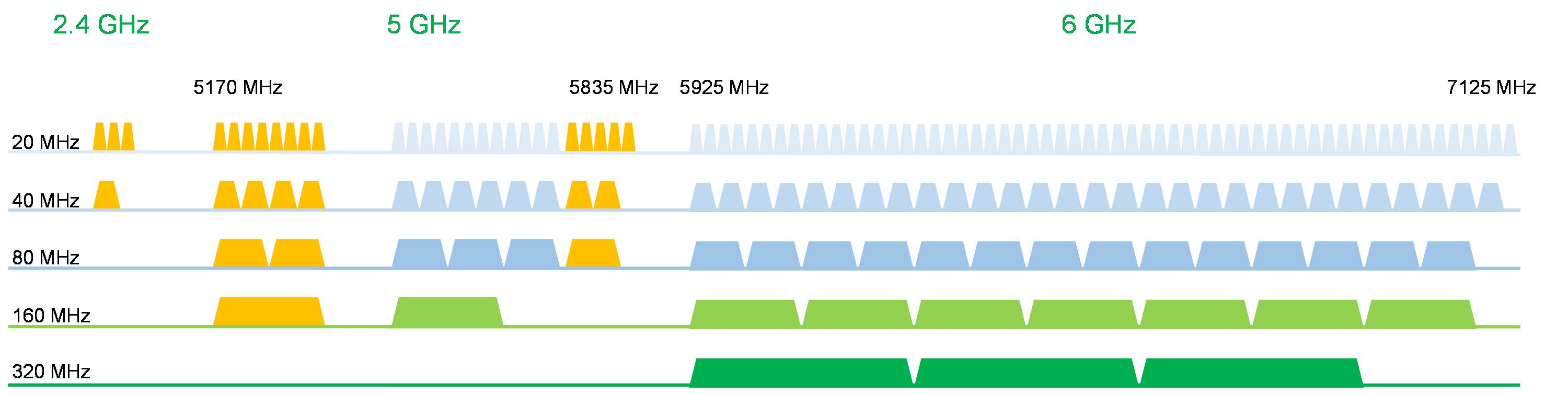
Wi-Fi 7 will operate at the 2.4 GHz, 5 GHz, and 6 GHz frequency bands, providing a bandwidth of 320 MHz at maximum. For flexible spectrum application, 240 MHz, 160+80 MHz, and 160+160 MHz bandwidth modes are supported.
Given the same number of spatial streams and same coding rate, Wi-Fi 7 can achieve twice the peak throughput of Wi-Fi 6.
Table 2 802.11 protocol bandwidth
|
Protocol |
Supported channel bandwidths |
|
802.11 |
20 MHz |
|
802.11a/b/g |
20 MHz |
|
802.11n |
20 MHz, 40 MHz |
|
802.11ac Wave1 |
20 MHz, 40 MHz, and 80 MHz |
|
802.11ac Wave2 |
20 MHz, 40 MHz, 80 MHz, 80+80 MHz, 160 MHz |
|
802.11ax |
20 MHz, 40 MHz, 80 MHz, 80+80 MHz, 160 MHz |
|
802.11be |
20 MHz, 40 MHz, 80 MHz, 80+80 MHz, 160 MHz, 160+80 MHz, 240 MHz, 160+160 MHz, 320 MHz |
4096-QAM modulation
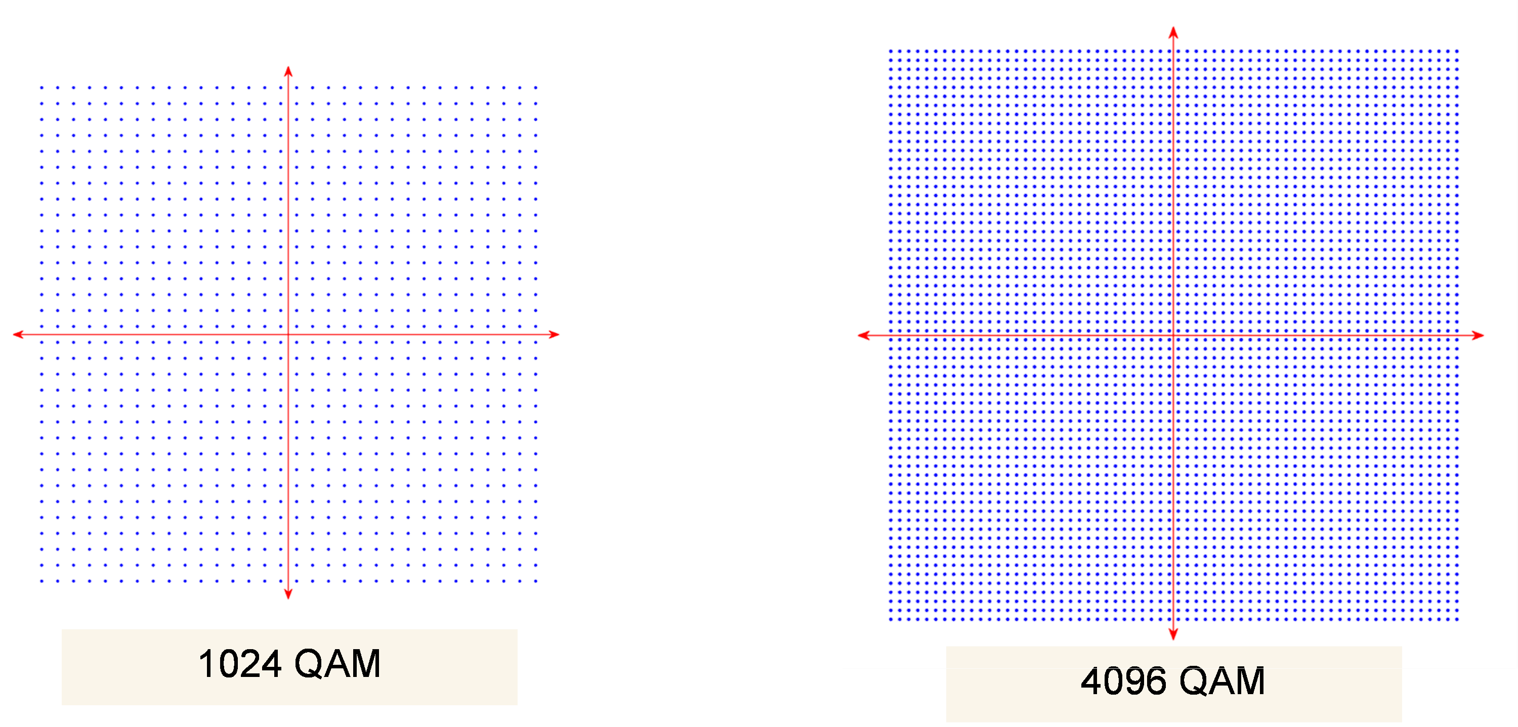
Wi-Fi 6 uses the highest-order modulation scheme 1024-QAM, where one modulation symbol carries 10 bits. Wi-Fi 7 will use a higher-order modulation scheme, 4096-QAM, where one modulation symbol can carry 12 bits. Theoretically, given the same coding rate, Wi-Fi 7 can achieve 20% higher transmission rate compared with Wi-Fi 6.
Figure 2 1024-QAM and 4096-QAM constellation diagram
Wi-Fi 7 supports 800ns, 1600ns, and 3200ns GIs. As shown in the following figure, using 800ns GI and 320 MHz bandwidth, Wi-Fi 7 can increase the maximum transmission rate from 1.2 Gbps to 2.88 Gbps in a single spatial stream.
Table 3 Transmission rate
|
MCS |
Modulation mode |
Data rate |
20 MHz (Mbps) |
40 MHz (Mbps) |
80 MHz (Mbps) |
160 MHz (Mbps) |
320 MHz (Mbps) |
|
0 |
BPSK |
2 |
8.6 |
17.2 |
36.0 |
72.1 |
144.1 |
|
1 |
QPSK |
2 |
17.2 |
34.4 |
72.1 |
144.1 |
288.2 |
|
2 |
4 |
25.8 |
51.6 |
108.1 |
216.2 |
432.4 |
|
|
3 |
16-QAM modulation |
2 |
34.4 |
68.8 |
144.1 |
288.2 |
576.5 |
|
4 |
4 |
51.6 |
103.2 |
216.2 |
432.4 |
864.7 |
|
|
5 |
64-QAM modulation |
3 |
68.8 |
137.6 |
288.2 |
576.5 |
1152.9 |
|
6 |
4 |
77.4 |
154.9 |
324.3 |
648.5 |
1297.1 |
|
|
7 |
6 |
86.0 |
172.1 |
360.3 |
720.6 |
1441.2 |
|
|
8 |
256-QAM modulation |
4 |
103.2 |
206.5 |
432.4 |
864.7 |
1729.4 |
|
9 |
6 |
114.7 |
229.4 |
480.4 |
960.7 |
1921.5 |
|
|
10 |
1024-QAM modulation |
4 |
129.0 |
258.1 |
540.4 |
1080.9 |
2161.8 |
|
11 |
6 |
143.4 |
286.8 |
600.4 |
1201.0 |
2401.9 |
|
|
12 |
4096-QAM |
3/4 |
154.9 |
309.7 |
648.5 |
1297.1 |
2594.1 |
|
13 |
5/6 |
172.1 |
344.1 |
720.6 |
1441.2 |
2882.4 |
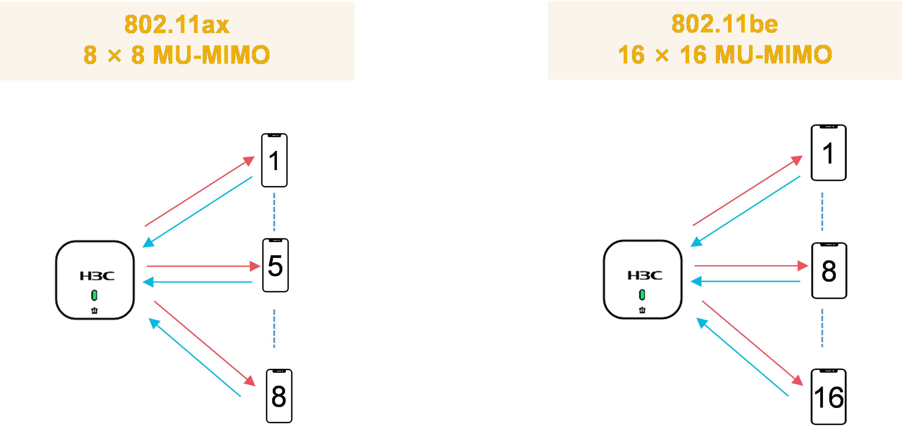
MIMO 16 × 16
Wi-Fi 7 increases the maximum number of spatial streams to 16, allowing a doubled theoretical transmission rate and associated station count than Wi-Fi 6.
Figure 3 MIMO 8 × 8 and MIMO 16 × 16
At the physical layer, Wi-Fi 7 can provide a transmission rate of up to 30 Gbps with 320 MHz bandwidth, 4096-QAM, and MIMO 16 × 16.
The maximum theoretical transmission rate will reach 46.1 Gbps, as shown in the following formula:

· ![]() —802.11be data rate.
—802.11be data rate.
· ![]() —Number of data bits per subcarrier.
—Number of data bits per subcarrier. ![]() =Number of bits per symbol × Bit rate × Number of subcarriers.
=Number of bits per symbol × Bit rate × Number of subcarriers.
· ![]() —Number of spatial
streams.
—Number of spatial
streams.
· ![]() —Guard interval.
—Guard interval.
The theoretical transmission rate is 46.1 Gbps with MCS 13, MIMO 16 × 16, and 320 MHz bandwidth.

Multilink device
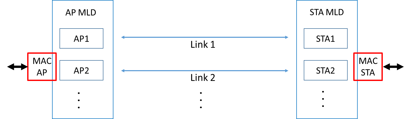
Wi-Fi 7 devices can operate at the 2.4 GHz, 5 GHz, and 6 GHz frequency bands. In actual application, transmissions at different subbands are not fully synchronized. If the primary channel is busy, packet transmission will be delayed even though the rest of the subchannels are idle. In addition, different parts of a channel might have different properties and interference levels, causing more packet losses and retransmissions. To consolidate spectrum frequency resources, Wi-Fi 7 defines multilink aggregation specifications in the protocol, including multilink architecture, multilink channel access, and multilink operation.
On an MLD, a device has at least two links to the wireless media, but with a single MAC address to the LLC layer. The MLD can perform dynamic link switching based on the scenario and wireless media state. This ensures highly-efficient and fast data transmission with low latency.
Figure 4 Multilink device
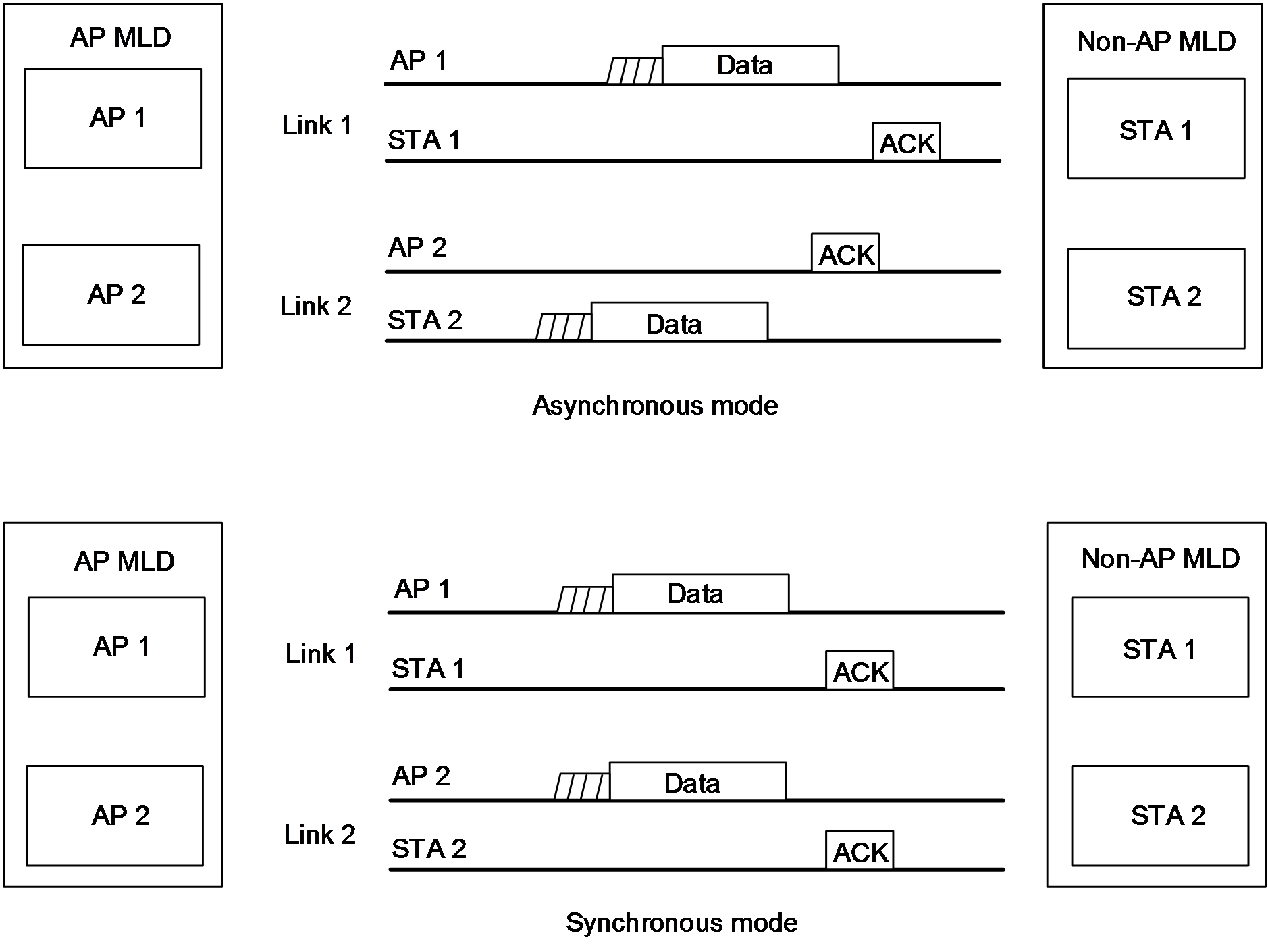
Multi-link operations include synchronous and asynchronous operations. In asynchronous multilink operation, multiple RF links perform channel detection, listen to and transmit and receive data independently. Asynchronous multilink operation is applicable to scenarios where the spectral distance between links is high and no interference exists between devices. If RF links within an MLD share the same antennas, antennas are located close to each other, or the spectrum emission mask is not ideal, power on one link will leak to another link. As a result, the leaked signal received by that link might be higher than the noise floor or even the received signal and significant interference will occur or even no useful signals can be received. Synchronous multilink operation avoids this issue by sending and receiving signals simultaneously.
Figure 5 Synchronous and asynchronous multilink operations (Reference: 802.11be Draft 1.3, Fig35-14)
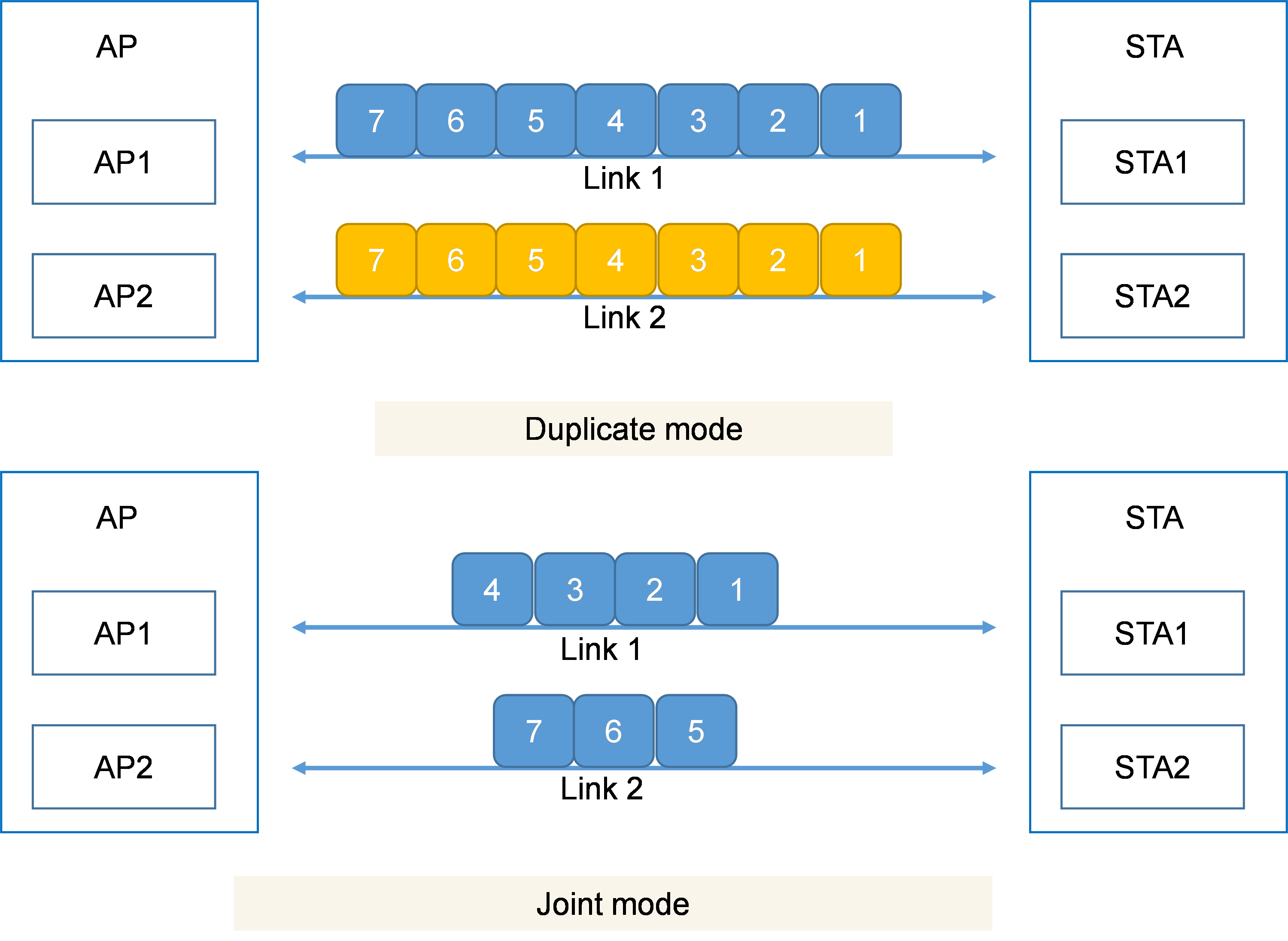
On an MLD, data can be transmitted in duplicate mode or joint mode. In duplicate mode, the receiver drops all the copies of a frame that are delivered later once it obtains that frame, which can lower transmission latency efficiently. In joint mode, the sender transmits frames over multiple available links. In addition, MLDs can exchange power management information about one link via another link` so that stations can enter working state only when necessary, which reduces energy consumption significantly.
Figure 6 Duplicate and joint transmission modes
OFDMA enhancement
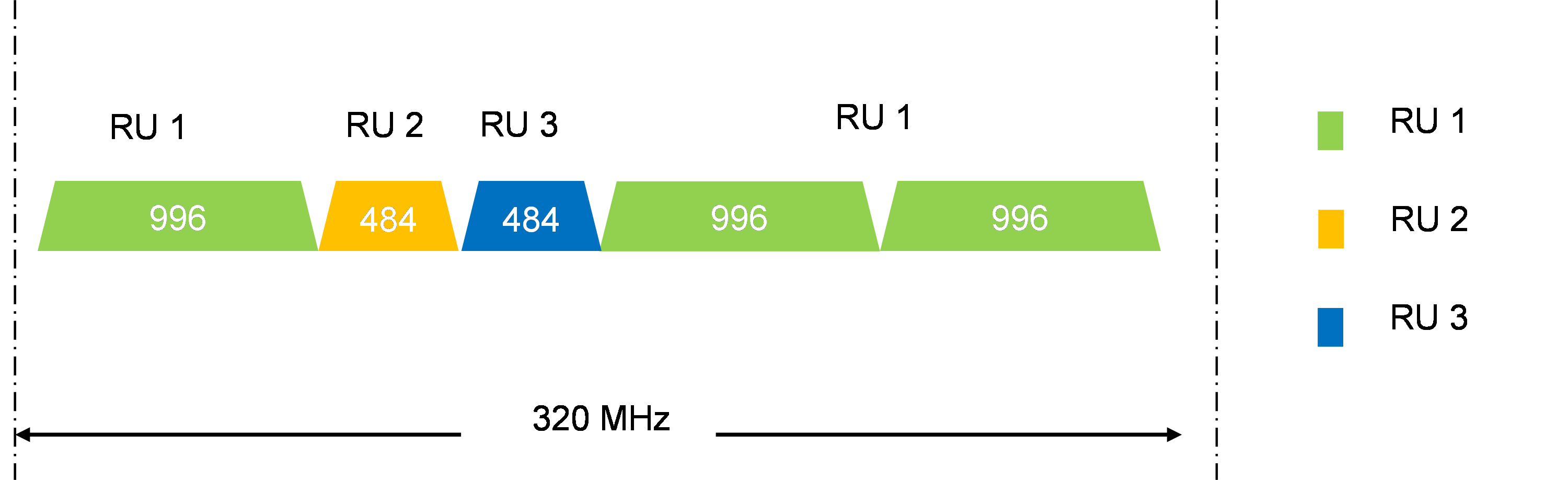
Multi-RU
The Wi-Fi protocols before Wi-Fi 6 typically use the orthogonal frequency division multiplexing (OFDM) modulation mode, which divides a channel into multiple subcarriers. OFDM is more resilient to electromagnetic interference, and can improve the transmission rate. However, only a single user can transmit data on all of the subcarriers at a given time. Wi-Fi 6 introduced orthogonal frequency division multiple access (OFDMA), a mature 4G cellular technology. It provides lower subcarrier bandwidth and adds the concept of RU. One channel can serve multiple users at the same time.
In Wi-Fi 6, each station is assigned only to a specific RU for transmitting or receiving frames, which significantly limits the flexibility of spectrum resource scheduling. Wi-Fi 7 allows multi-RU assignment to a single station, and allows combination of RUs of different sizes. For trade-off between complexity and spectrum efficiency, small-size RUs (lower than 20 MHz) can only be combined with small-size RUs, large-size RUs (equal to or higher than 20 MHz) can only be combined with large-size RUs, and mixture of small-size and large-size RUs is not allowed.
Figure 7 20 MHz multi-RU example
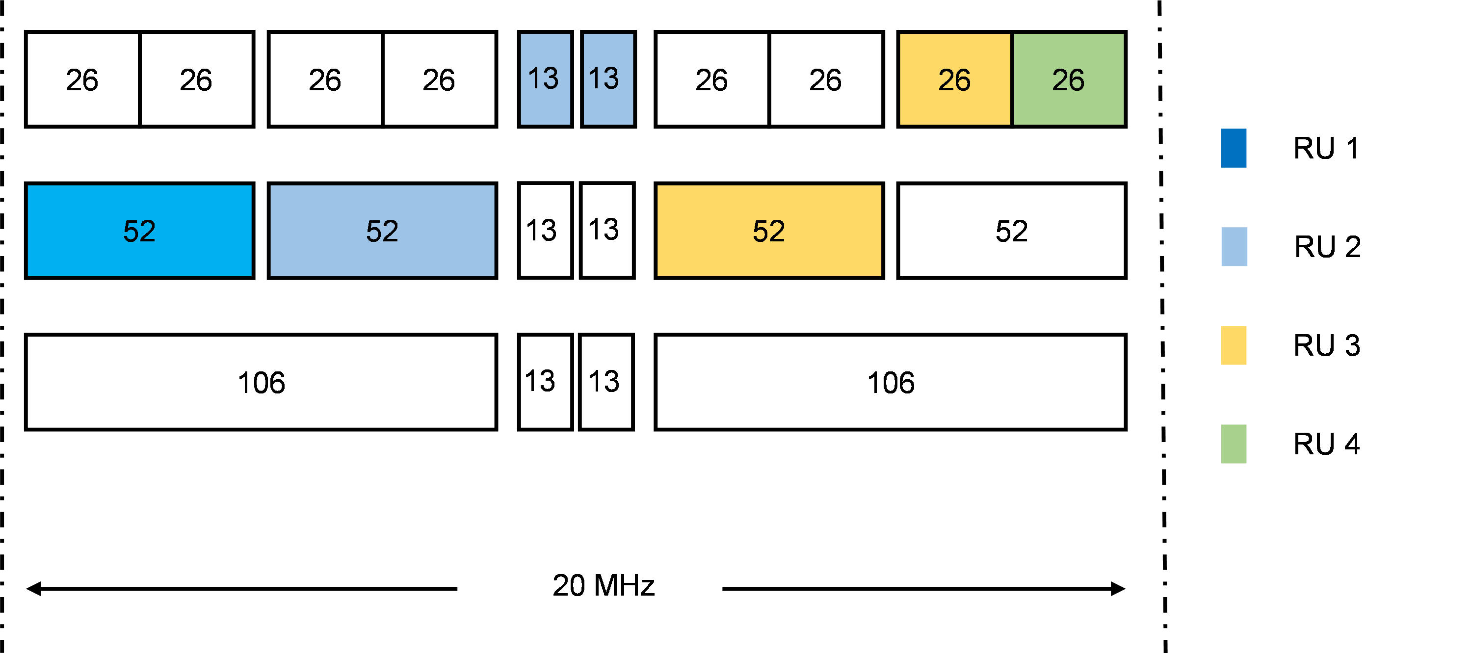
Figure 8 Higher bandwidth multi-RU example
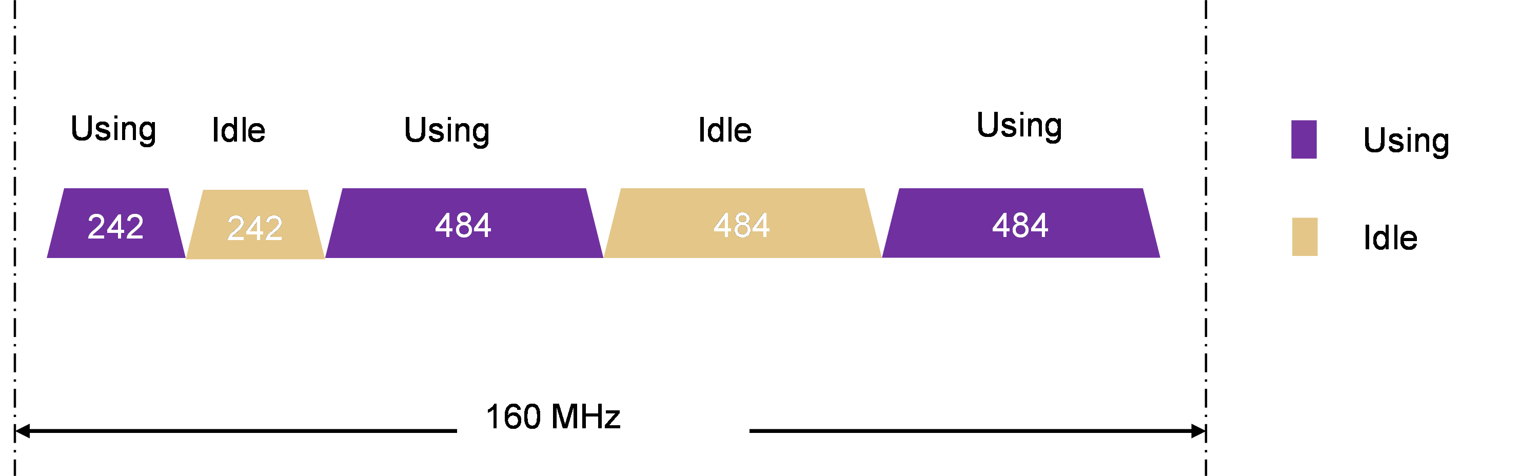
Preamble puncturing
Preamble puncturing is an optional feature introduced in Wi-Fi 6. It improves spectral efficiency by allowing a punctured portion of the spectrum channel to be transmitted. Wi-Fi 7 extended the preamble puncturing patterns up to 240/320 MHz and provides more flexible puncturing mechanisms.
Figure 9 Preamble puncturing
Multi-AP coordination
Wi-Fi 6 only supports transmission to and from a single AP and spatial sharing between APs and stations is not available. Wi-Fi 7 extends its ability to improvement of AP performance and availability and multi-AP transmissions.
Multi-AP transmission modes include the following:
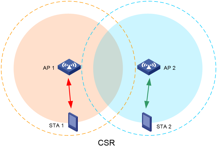
· Coordinated spatial reuse (CSR)
· Joint transmission (JTX)
· Coordinated orthogonal frequency-division multiple access (C-OFDMA)
· Coordinated beamforming (CBF)
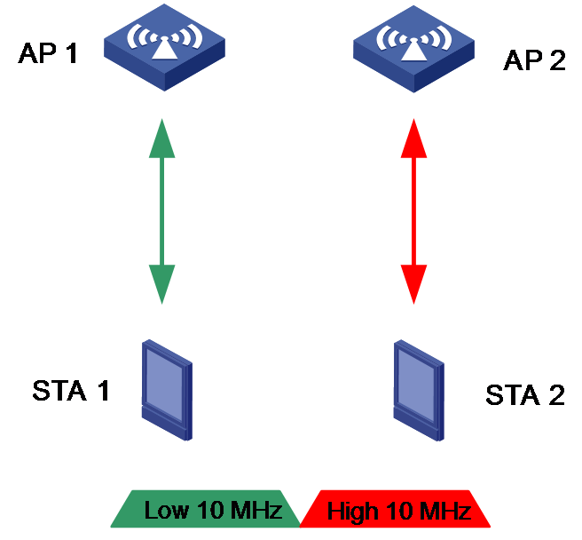
CSR
In Wi-Fi 5 and before, adjacent channel interference is controlled by dynamically adjusting the CCA threshold and ignoring the weak interference signal of the same frequency for concurrent transmission. Wi-Fi 6 introduced the BSS coloring feature, which allows each BSS to use a unique color. Each station can identify transmissions from another network and take right actions accordingly. Wi-Fi 7 controls the transmission power between APs in a coordinated way to reduce interference and maximize the network-wide throughput.
Figure 10 CSR
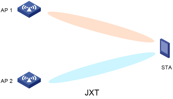
JTX
JTX can be regarded as a virtual MIMO system that contains multiple APs and multiple stations. Multiple APs provide services to one station. It enables fast association of stations with an optimal AP and improves re-connection speed when users move around.
Figure 11 JTX
C-OFDMA
OFDMA divides the whole bandwidth into a series of OFDM subcarrier sets called RUs and assigns different RUs to different users. However, conflicts still occur when interference exists. Wi-Fi 7 extends OFDMA from a single AP to multiple APs, allowing multiple APs and multiple stations to share RUs. With C-OFDMA, APs coordinate to share OFDMA resources for all stations, avoiding RU conflicts and improving spectrum utilization.
Figure 12 C-OFDMA
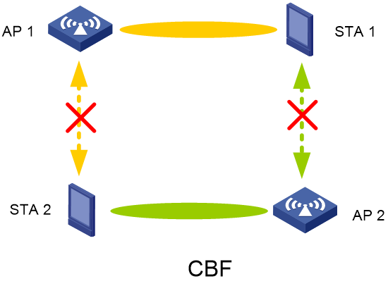
CBF
In WLANs that use a Wi-Fi standard earlier than Wi-Fi 7, beamforming is only performed by a single AP independently, resulting in uncontrollable inter-AP interference. To mitigate interference, EHT recommends CBF each transmit signals on the intended stations.
Figure 13 CBF
Reference
· Amendment 8: Enhancements for extremely high throughput (EHT) in Part 11: Wireless LAN Medium Access Control (MAC) and Physical Layer (PHY) Specifications of IEEE P802.11be™/D1.3 Draft Standard for Information technology— Telecommunications and information exchange between systems Local and metropolitan area networks— Specific requirements
· Current Status and Directions of IEEE 802.11be, the Future Wi-Fi 7
