- Table of Contents
- Related Documents
-
| Title | Size | Download |
|---|---|---|
| 01-Wireless AC Configuration Examples | 163.34 KB |
Contents
Introduction
This document outlines the configuration process for the wireless AC of routers.
Prerequisites
This document is not strictly aligned with specific software or hardware versions. If discrepancies arise during use, please refer to the actual device conditions for guidance.
This document's configurations were established and verified in a laboratory setting using devices with default factory settings. Before configuring, ensure there are no conflicts with existing settings and the examples provided.
This document assumes you are familiar with wireless AC features.
Versions used
This configuration example was set up and verified on the MSR830-10HI router, version Release 6749L04.
Configuration examples
Networking requirements
As shown in Figure 1, the AP connects to the Router (AC) through a PoE switch. The requirements are as follows:
· The client can access the router via the 2.4Ghz and 5Ghz wireless networks deployed by the AP and automatically obtain an IP address from VLAN 20.
· The AP can automatically obtain an IP address from VLAN 10 subnet.
Figure 1 Wireless AC Typical Configuration Network Diagram

Configuration approach
· To configure 2.4G and 5G wireless service templates on the router, this example sets specific parameters to enhance the client's wireless experience, taking into account the surrounding environment of the AP:
|
Wireless service template |
SSID |
Working mode |
Work channel |
Maximum transmission rate |
|
2.4G |
service1 |
802.11g |
6 |
19dm |
|
5G |
service2 |
802.11ac |
157 |
19dm |
· VLAN 10 and VLAN 20 need to be configured on the Router. VLAN 10 is for message exchange between the Router and AP, while VLAN 20 is bound to the 2.4G and 5G wireless service templates.
· To allow both APs and clients to automatically obtain IP addresses, the DHCP Server function must be enabled on the router.
Restrictions and guidelines
· The wireless operating modes, channels, and maximum transmission rates can be adjusted based on actual usage conditions.
· Interfaces connecting routers to PoE switches, as well as those linking APs to PoE switches, must be configured as Trunk, permitting passage of management and service VLANs for APs with the default VLAN set as the AP's management VLAN.
· You can either create a manual AP or configure an automatic AP to get the AP online. This example uses a manual AP creation, and the AP's serial number can be found on the label at the back of the AP device.
Configuration preparation
· Connect your PC to the router's LAN port using an Ethernet cable and configure a static IP address on the PC as 192.168.0.X/23. Then open a web browser and enter the router's management IP address (https://192.168.0.1) to access the Web management interface.
· Confirm that your PC has serial terminal software installed and is connected to the Switch's console port via a serial cable. Launch the terminal software and configure the appropriate parameters to connect to the Switch's backend interface.
Procedures
Configuring Router
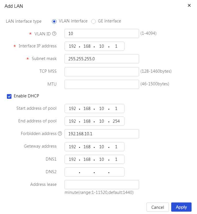
1. Create VLAN 10.
Divide VLAN 10, configure the interface's IP address, and enable its DHCP service.
Navigate to the Network Settings > LAN Configuration in the device's web management interface to access the LAN configuration page.
Click Add to access the LAN configuration page.
In the LAN Interface Type configuration, select the VLAN interface.
Enter 10 in the VLAN ID configuration field.
Enter 192.168.10.1 in the Interface IP Address configuration field.
In the subnet mask configuration field, enter 255.255.255.0.
Check the radio button next to Enable DHCP Service to activate the DHCP service on the interface.
For other configuration items, keep the default settings and click OK to save the configuration.
Figure 2 Creating VLAN 10
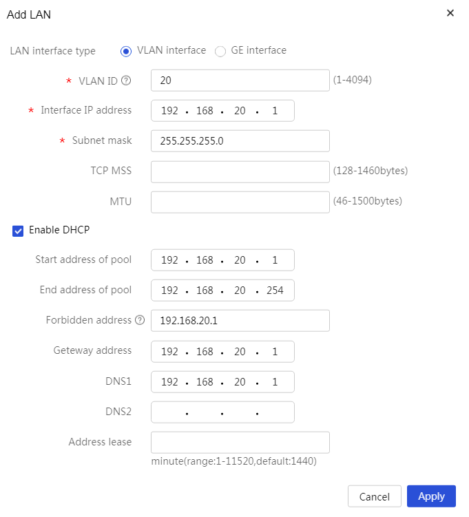
2. Create VLAN 20.
Divide VLAN 20, configure the interface's IP address, and enable its DHCP service.
Navigate to the Network Settings > LAN Configuration in the device's web management interface to access the LAN configuration page.
Click Add to access the LAN configuration page.
In the LAN Interface Type configuration, select the VLAN interface.
Enter 20 in the VLAN ID configuration field.
Enter 192.168.20.1 in the Interface IP Address configuration field.
In the subnet mask configuration field, enter 255.255.255.0.
Check the radio button next to Enable DHCP Service to activate the DHCP service on the interface.
For other configuration items, keep the default settings and click OK to save the configuration.
Figure 3 Creating VLAN 20
3. Configure the GE4 interface.
Configure the GE4 interface to pass through both VLAN 10 and VLAN 20, and set the interface's PVID to 10.
Navigate to the Network Settings > LAN Configuration in the device's web management interface to access the LAN configuration page.
Click on the VLAN Division tab to access the VLAN configuration page.
Click the edit icon in the operation column for the GE4 interface to enter the detailed port configuration page.
At the PVID configuration option, select 10.
Click on VLAN 20 in the available VLAN box to add VLAN 20 to the selected VLAN box.
Click OK to save the configuration.
4. Manually create an AP.
Create the AP manually to establish a connection between the AP and AC.
In the device's web management interface, select Wireless AC from the navigation bar to access the wireless AC configuration page.
Select Quick Setup > Add AP > Add AP from the left sidebar to access the Add AP page.
In the AP Name settings, enter ap1 (customization is allowed).
In the AP Model configuration option, select WA4320H. (Choose the AP model to use.)
In the configuration for AP Serial Number, enter 219801A0YG819BE005JC. (Select the AP serial number to use.)
For other options, keep the default settings and click OK to complete the AP creation.
5. Configure 2.4G Radio Frequency.
5.Configure the 2.4G radio frequency to operate in 802.11g mode, on channel 6, with a maximum transmission power of 19dBm.
a. To access the RF configuration page, select Wireless Settings > RF Management > RF Configuration from the navigation bar on the left side of the wireless AC interface.
Click More on the corresponding row of All APs RF to enter the RF page for all APs.
b. Click the operation button on the corresponding row for 2.4G RF to access the AP's RF configuration page.
Click Modify RF Mode to enter the RF mode editing page.
Select 802.11g under the RF Mode setting.
Choose channel 6 under the Configure Channel setting.
Enter 19 for the Maximum Power setting.
Keep other options at their default settings and click OK to complete the 2.4G RF configuration.
6. Configure 5G Radio Frequency.
Set the 5G RF to work in 802.11ac mode, on channel 157, with a maximum transmission power of 19 dBm.
a. On the AP RF page, click the operation button for 5G RF to enter the RF configuration page for the AP.
b. Click Modify RF Mode to go to the RF mode modification page.
c. Select 802.11g for the RF Mode setting.
d. Choose channel 6 for the Configure Channel setting.
e. Enter 19 for the Maximum Power setting.
f. Keep other options at their default settings and click OK to complete the 5G RF setup.
7. Create a 2.4G Wireless Service Template.
Create a 2.4G wireless service template named map1, set the SSID to service1, configure clients to join VLAN 20 upon connecting through map1, and activate the wireless service template.
a. In the wireless AC configuration interface, select Quick Setup > Add Wireless Service > New Wireless Service from the left navigation bar to enter the new wireless service page.
b. Enter map1 for the Wireless Service Name setting.
c. Select service1 for the SSID setting.
d. Choose to enable under the Wireless Service setting.
e. Input 20 for the Default VLAN setting.
8. Create a 5G Wireless Service Template.
Create a 5G wireless service template named map2, set the SSID to service2, configure clients to join VLAN 20 after connecting through map1, and activate the service template.
a. In the wireless AC configuration interface, select Quick Setup > Add Wireless Service > New Wireless Service from the left navigation bar to enter the new wireless service page.
a. Enter map2 for the Wireless Service Name setting.
b. Select service2 for the SSID setting.
c. Choose to enable under the Wireless Service setting.
d. Input 20 for the Default VLAN setting.
9. Bind the 2.4G wireless service template to the 2.4G RF.
a. On the new wireless service page, click the OK and Enter Advanced Settings to proceed to the advanced settings page.
b. Click Bind on the page to access the binding page.
c. Move ap1 (Radio2 2.4G) from the list of available options to the list of selected options.
d. Leave other options at their default configurations and click OK to finalize the binding of the wireless service template with the RF.
10. Bind the 5G wireless service template to the 5G RF.
a. On the new wireless service page, click OK and Enter Advanced Settings to access the advanced settings page.
b. Click Bind on the page to enter the binding page.
c. Move ap1 (Radio1 5G) from the list of available options to the list of selected options.
d. Keep other options at their default settings and click OK to complete the binding of the wireless service template and RF.
Configuring Switch
1. Configure VLANs and interfaces.
<L2 switch> system-view
[L2 switch] VLAN 10
[L2 switch-VLAN10] quit
[L2 switch] VLAN 20
[L2 switch-VLAN20] quit
[L2 switch] interface gigabitethernet 1/0/1
[L2 switch-GigabitEthernet1/0/1] port link-type trunk
[L2 switch-GigabitEthernet1/0/1] port trunk pvid VLAN 10
[L2 switch-GigabitEthernet1/0/1] port trunk permit VLAN 10 20
[L2 switch-GigabitEthernet1/0/1] quit
[L2 switch] interface gigabitethernet 1/0/2
[L2 switch-GigabitEthernet1/0/2] port link-type trunk
[L2 switch-GigabitEthernet1/0/2] port trunk pvid VLAN 10
[L2 switch-GigabitEthernet1/0/2] port trunk permit VLAN 10 20
[L2 switch-GigabitEthernet1/0/2] quit
2. Enable the remote power supply feature via the PoE interface.
[L2 switch] interface gigabitethernet 1/0/2
[L2 switch-GigabitEthernet1/0/2] poe enable
[L2 switch-GigabitEthernet1/0/2] quit
Verifying the configuration
For more information on AP details, observe that the AP has successfully established a tunnel connection with the AC and entered the Run state.
[Router]display wlan ap name ap1 verbose
AP name : ap1
AP ID : 1
AP group name : default-group
State : Run
Backup type : Master
Online time : 0 days 4 hours 7 minutes 27 seconds
System uptime : 0 days 4 hours 17 minutes 4 seconds
Model : WA4320H
Region code : CN
Region code lock : Disabled
Serial ID : 219801A0YG819BE005JC
MAC address : 9429-2f93-14c0
IP address : 192.168.0.4
UDP control port number : 25930
UDP data port number : 25930
H/W version : Ver.B
S/W version : R2439P01
Boot version : 7.21
USB state : Disabled
Power level : N/A
Power info : N/A
Description : Not configured
Priority : 4
Echo interval : 10 seconds
Echo count : 3 counts
...displays brief information...
Clients can connect to the 2.4G and 5G networks through the wireless signals of service1 and service2, indicating successful configuration. The command display wlan client verbose can be used to view the connection details of online users.
[Router]display wlan client verbose
Total number of clients: 2
MAC address : 424a-b9db-91bf
IPv4 address : 192.168.20.3
IPv6 address : N/A
Username : N/A
AID : 2
AP ID : 1
AP name : ap1
Radio ID : 2
SSID : service1
BSSID : 9429-2f93-14d0
VLAN ID : 20
Sleep count : 22
Wireless mode : 802.11g
Supported rates : 1, 2, 5.5, 6, 9, 11,
12, 18, 24, 36, 48, 54 Mbps
QoS mode : WMM
Listen interval : 20
RSSI : 54
Rx/Tx rate : 0/0 Mbps
Speed : N/A
Authentication method : Open system
Security mode : PRE-RSNA
AKM mode : Not configured
Cipher suite : N/A
User authentication mode : Bypass
WPA3 status : N/A
Authorization CAR : N/A
Authorization ACL ID : N/A
Authorization user profile : N/A
Roam status : N/A
Key derivation : N/A
PMF status : N/A
Forwarding policy name : Not configured
Online time : 0days 0hours 0minutes 6seconds
FT status : Inactive
...displays brief information...
