- Table of Contents
- Related Documents
-
| Title | Size | Download |
|---|---|---|
| 01-Text | 6.46 MB |
Contents
General safety recommendations
Examining the installation site
2 Installing and removing the device
Installation and removal flowchart
About the SL-2U-FR-S short rail kit
Attaching inner rails to the device
Attaching outer rails to the rack
Installing the device in the rack
Connecting a mouse, keyboard, and monitor
Removing the device from a rack
3 Powering on, powering off, and rebooting the device
Flowchart for logging in to the device
Logging in to the device from HDM
Logging in to HDM from the Web interface
Logging in to the remote console
Logging in to the WBC Monitoring Platform
Logging in to the device from the WBC Monitoring Platform
Logging in to the device from a local PC
Logging in to the Oasis platform from the local PC
Logging in to the license server
Monitoring the temperature and humidity in the equipment room
6 Appendix A Chassis views and technical specifications
8 Appendix C Optional transceiver modules
Transceiver module, fiber connector, and optical fiber views
Transceiver module specifications
1 Preparing for installation
Safety sign conventions
To avoid bodily injury or damage to the device or its components, make sure you are familiar with the safety signs on the device chassis or its components.
|
Sign |
Description |
|
Circuit or electricity hazards are present. Only H3C authorized or professional device engineers are allowed to service, repair, or upgrade the device.
To avoid bodily injury or damage to circuits, do not open any components marked with the electrical hazard sign unless you have authorization to do so. |
|
|
Electrical hazards are present. Field servicing or repair is not allowed.
To avoid bodily injury, do not open any components with the field-servicing forbidden sign in any circumstances. |
|
|
The surface or component might be hot and present burn hazards.
To avoid being burnt, allow hot surfaces or components to cool before touching them. |
|
|
The device or component is heavy and requires more than one people to carry or move.
To avoid bodily injury or damage to hardware, do not move a heavy component alone. In addition, observe local occupational health and safety requirements and guidelines for manual material handling. |
|
|
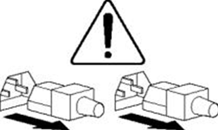
|
The device is powered by multiple power supplies.
To avoid bodily injury from electrical shocks, make sure you disconnect all power supplies if you are performing offline servicing. |
Safety recommendations
To avoid any equipment damage or bodily injury, read the following safety recommendations before installation. Note that the recommendations do not cover every possible hazardous condition.
Safety symbols
When reading this document, note the following symbols:
![]() WARNING means an alert that calls attention to important information that if
not understood or followed can result in personal injury.
WARNING means an alert that calls attention to important information that if
not understood or followed can result in personal injury.
![]() CAUTION means an alert that calls attention to important information that if
not understood or followed can result in data loss, data corruption, or damage
to hardware or software.
CAUTION means an alert that calls attention to important information that if
not understood or followed can result in data loss, data corruption, or damage
to hardware or software.
General safety recommendations
· Make sure the installation site is flat, vibration-free, and away from electromagnetic interferences. Make sure ESD and anti-slip measures are in place.
· Keep the chassis and installation tools away from walk areas.
· Do not place the device on an unstable case or desk. The device might be severely damaged in case of a fall.
· Keep the chassis clean and dust-free.
· Do not place the device near water or in a damp environment. Prevent water or moisture from entering the device chassis.
· Install the device in a standard 19-inch rack.
· If multiple racks exist in an equipment room, connect these racks for stability purposes and ease of installation.
· Make sure the rack is securely seated with the supporting legs closely contacting the floor. All the weight must be supported by the supporting legs.
· Remove a maximum of one device from a rack at one time.
· Use two people to install the device to or pull the device out of a rack to ensure stability. If the installation position is above the chest, use one more people to help adjust the device orientation.
· Make sure the rack is securely seated on the floor before installing or removing the device.
· To ensure good ventilation, install blanks over unused rack space and the empty power supply slot.
· To ensure good ventilation, make sure the air inlet and outlet vents of the device are not blocked. If you are to install multiple devices in a rack, make sure there is a minimum of 2 mm (0.08 in) clearance between every two devices.
· Remove all cables from the device before moving it.
· Make sure the output voltage of the power supplies is as required.
· Use a screwdriver to fasten screws.
· After you move the device from a location below 0°C (32°F) to the equipment room, follow these guidelines to prevent condensation:
¡ Wait a minimum of 30 minutes before unpacking the device.
¡ Wait a minimum of 2 hours before powering on the device.
Electricity safety
|
|
WARNING! If you put the device in standby mode
(system LED in amber) with the |
|
|
CAUTION: As a best practice to avoid device impairment caused by voltage fluctuation and power failure, use a UPS as the external power source. |
· Carefully examine your work area for possible hazards, such as moist floors.
· Locate the emergency power-off switch in the room before installation. Shut off the power immediately if an accident occurs. Remove the power cord if necessary.
· Do not work alone when you operate the device with power on.
· Always verify that the power has been disconnected when you perform operations that require the device to be powered off.
· To avoid device damage or bodily injury, use the power cord supplied with the device.
· Do not use the supplied power cord on any other devices.
· Power off the device before installing or removing any non-hot-swappable hardware options.
Laser safety
|
|
WARNING! · Disconnected optical fibers or transceiver modules might emit invisible laser light. Do not stare into beams or view directly with optical instruments when the router is operating. · Before you remove the optical fiber connector from a fiber port, execute the shutdown command in interface view to shut down the port. |
|
|
CAUTION: · Install dust caps for open optical fiber connectors to protect them from contamination and ESD damage. · Insert dust plugs into open fiber ports and transceiver module ports to protect them from contamination and ESD damage. |
Examining the installation site
The device can only be used indoors. For the device to operate correctly and have a prolonged service time, the installation site must meet the following requirements.
Temperature and humidity
Make sure the temperature and humidity in the equipment room meet the requirements described in Table1-2.
· Lasting high relative humidity can cause poor insulation, electricity leakage, mechanical property change of materials, and metal corrosion.
· Lasting low relative humidity can cause washer contraction and ESD and cause problems including loose mounting screws and circuit failure.
· High temperature can accelerate the aging of insulation materials and significantly lower the reliability and lifespan of the device.
Table1-2 Temperature and humidity requirements for the equipment room
|
Temperature |
Humidity |
|
· Operating temperature: 5°C to 45°C (32°F to 113°F) · Storage temperature: –40°C to +70°C (–40°F to +158°F) |
· Operating humidity: 8% RH to 90% RH, noncondensing · Storage humidity: 5% RH to 95% RH, noncondensing |
|
|
NOTE: The ventilation performance of the device depends on the installation density and ventilation in the rack. In a high-density environment, the available operating temperature might decrease. |
Cleanliness
Dust buildup on the chassis might result in electrostatic adsorption, which causes poor contact of metal components and contact points, especially when indoor relative humidity is low. In the worst case, electrostatic adsorption can cause communication failure.
Table1-3 Dust concentration limit in the equipment room
|
Substance |
Particle diameter |
Concentration limit |
|
Dust particles |
≥ 5 µm |
≤ 3 x 10⁴ particles/m3 (No visible dust on desk in three days) |
|
Dust (suspension) |
≤ 75 µm |
≤ 0.2 mg/m3 |
|
Dust (sedimentation) |
75 µm to 150 µm |
≤ 1.5 mg/(m2h) |
|
Sand |
≥ 150 µm |
≤ 30 mg/m3 |
The equipment room must also meet limits on salts, acids, and sulfides to eliminate corrosion and premature aging of components, as shown in Table1-4.
Table1-4 Harmful gas limits in the equipment room
|
Gas |
Max. (mg/m3) |
|
SO2 |
0.2 |
|
H2S |
0.006 |
|
NH3 |
0.05 |
|
Cl2 |
0.01 |
|
NO2 |
0.04 |
Cooling
To provide adequate cooling for the device, follow these guidelines:
· Reserve a minimum clearance of 10 cm (3.94 in) around the device.
· Make sure the installation site has a good cooling system.
· Identify the cold and hot aisle arrangement at the installation site, and make sure the device draws in air from the cold aisle and exhausts air to the hot aisle.
· Identify the airflow directions of the upper and lower devices, and make sure hot air exhausted from the lower devices does not circulate into the upper devices.
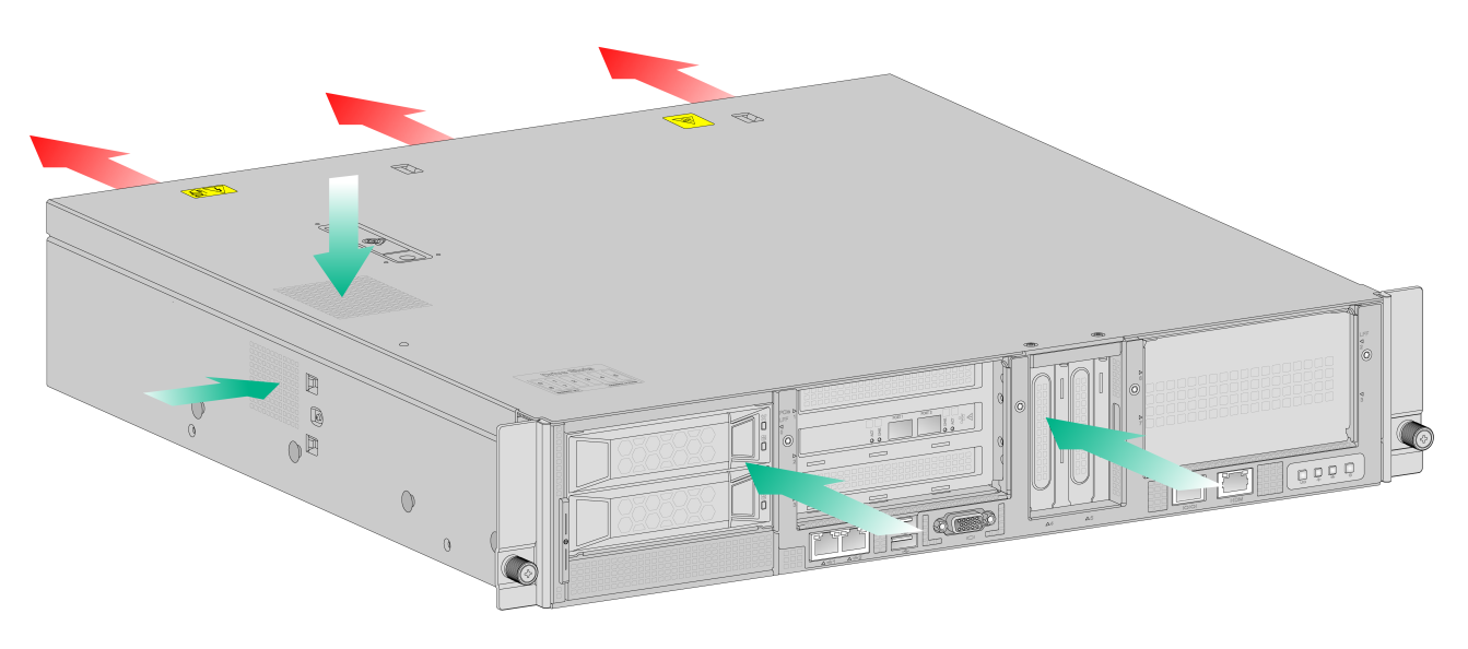
Figure1-1 Airflow through the device
Rack
To rack-mount the device, make sure the rack meets the following requirements:
· The rack is sturdy enough to support the weights of the device and its accessories.
· The rack is grounded reliably.
· The rack can accommodate the device. See Table1-6 for the requirements for rack dimensions.
Table1-5 Requirements for rack dimensions
|
Installation method |
Chassis dimensions |
Distance between the front and rear rack posts |
Rack requirements |
|
Using mounting brackets and an SL-2U-FR-S short rail kit |
· Height—87 mm (3.43 in), 2 RU · Width—440 mm (17.32 in) · Total depth—450 mm (17.72 in) |
350 to 450 mm (13.78 to 17.72 in) |
· Depth (recommended)—A minimum of 800 mm (31.50 in). · Distance between the front rack posts and front door—A minimum of 100 mm (3.94 in). · Distance between the front rack posts and rear door—A minimum of 550 mm (21.65 in). |
|
|
IMPORTANT: For the rack door to close easily, make sure the rack meets the depth requirements described in Table1-6. |
|
|
NOTE: The total depth is the depth of the chassis when it is fully configured with components and cables. |
Altitude
To ensure correct operation of the device, make sure the room altitude meets the requirements as described in Table1-6.
Table1-6 Altitude requirements
|
Item |
Description |
|
Operating altitude |
–60 m to +3000 m (–196.85 ft to +9842.52 ft) The allowed maximum temperature decreases by 0.33°C (32.59°F) as the altitude increases by 100 m (328.08 ft) from 900 m (2952.76 ft) |
|
Storage altitude |
–60 m to +5000 m (–196.85 ft to +16404.20 ft) |
ESD prevention
To prevent electrostatic discharge (ESD), follow these guidelines:
· Make sure the rack is reliably grounded.
· Take dust-proof measures for the equipment room.
· Maintain the humidity and temperature in the equipment room at acceptable levels.
· When working with the device, always wear an ESD wrist strap and ESD garment. Make sure the wrist strap makes good skin contact and is reliably grounded.
· Use foldable antistatic mat and portable repair kit.
EMI
All electromagnetic interference (EMI) sources, from outside or inside of the device and application system, adversely affect the device in the following ways:
· A conduction pattern of capacitance coupling.
· Inductance coupling.
· Electromagnetic wave radiation.
· Common impedance (including the grounding system) coupling.
To prevent EMI, use the following guidelines:
· Take effective measures to filter interference from the power grid.
· Keep the device far away from radio transmitting stations, radar stations, and high-frequency devices.
· Use electromagnetic shielding, for example, shielded interface cables, when necessary.
· To prevent signal ports from getting damaged by overvoltage or overcurrent caused by lightning strikes, route interface cables only indoors.
Lightning protection
To enhance lightning protection for the device, follow these guidelines:
· Make sure the AC power outlet is reliably grounded.
· Install a surge protected power strip at the power input end.
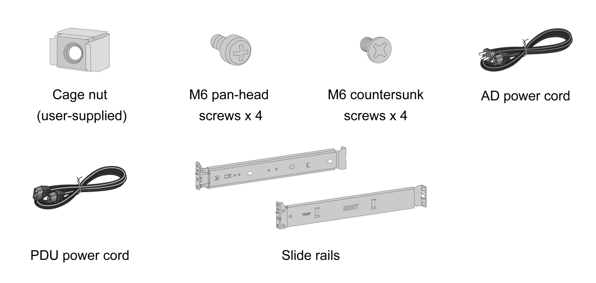
Installation accessories
Figure1-2 Installation accessories
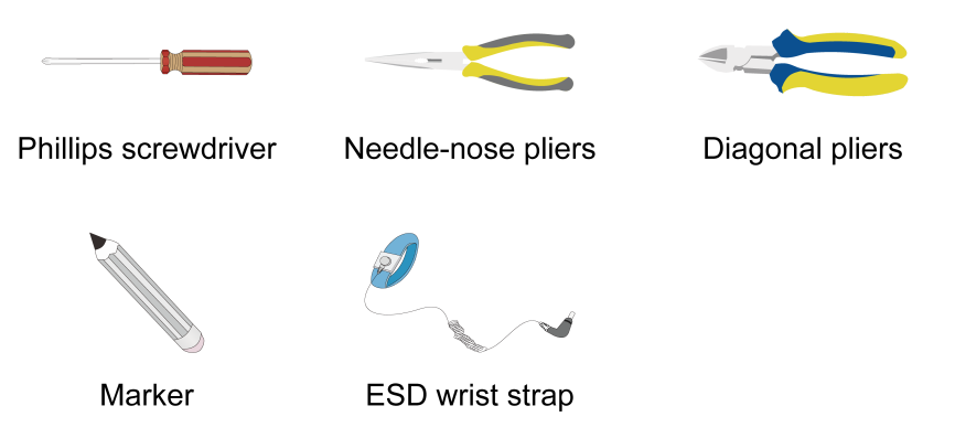
Installation tools
No installation tools are provided with the device. Prepare them yourself as required.
Figure1-3 Installation tools
Pre-installation checklist
Table1-7 Pre-installation checklist
|
Item |
Requirements |
Result |
|
|
Installation site |
Ventilation |
· A minimum clearance of 10 cm (3.9 in) is reserved around the chassis. · The installation site has a good ventilation system. |
|
|
Operating temperature |
5°C to 45°C (32°F to 113°F). |
|
|
|
Operating humidity |
8% RH to 90% RH, noncondensing |
|
|
|
Cleanliness |
· Dust concentration ≤ 3 x 10⁴ particles/m3. · No visible dust on desk within three days. |
|
|
|
ESD prevention |
· The device is reliably grounded. · Dust-proof measures are taken in the equipment room. · Humidity and temperature are maintained in the acceptable range. |
|
|
|
EMI prevention |
· Effective measures are taken for filtering interference from the power grid. · The protection ground of the device is away from the grounding facility of power equipment or lightning protection grounding facility. · The device is far away from radio transmitting stations, radar stations, and high-frequency devices. · Electromagnetic shielding, for example, shielded interface cables, is used as required. |
|
|
|
Lightning protection |
· The AC power source is reliably grounded. · (Optional.) Network port lightning protectors are available. |
|
|
|
Electricity safety |
· A UPS is available. · The power-off switch in the equipment room is identified and accessible so that the power can be immediately shut off when an accident occurs. |
|
|
|
Rack installation |
· The rack has good ventilation performance. · The rack is stable and strong enough to support the device and the accessories attached to the device. · The rack size is suitable for the device installation. · The clearance around the rack meets the ventilation requirements. |
|
|
|
Safety precautions |
The device is far away from any sources of heat or moisture. |
|
|
|
Accessories |
Installation accessories supplied with the device are available. |
|
|
|
Reference |
· Documents shipped with the device are available. · Online documents are available. |
|
|
2 Installing and removing the device
Prerequisites
· You have read "Preparing for installation" carefully.
· All requirements in "Preparing for installation" are met.
Installation and removal flowchart
Figure2-1 Installation flowchart

Figure2-2 Removal flowchart

Installing the device
|
|
CAUTION: Keep the tamper-proof seal on a mounting screw on the chassis cover intact, and if you want to open the chassis, contact H3C for permission. Otherwise, H3C shall not be liable for any consequence. |
About the SL-2U-FR-S short rail kit
The SL-2U-FR-S short rail kit shipped with the device includes left and right slide rails. Each slide rail has an outer rail and an inner rail. The outer rail is installed on the rack, and the inner rail is installed on the device.
Figure2-3 Left outer rail
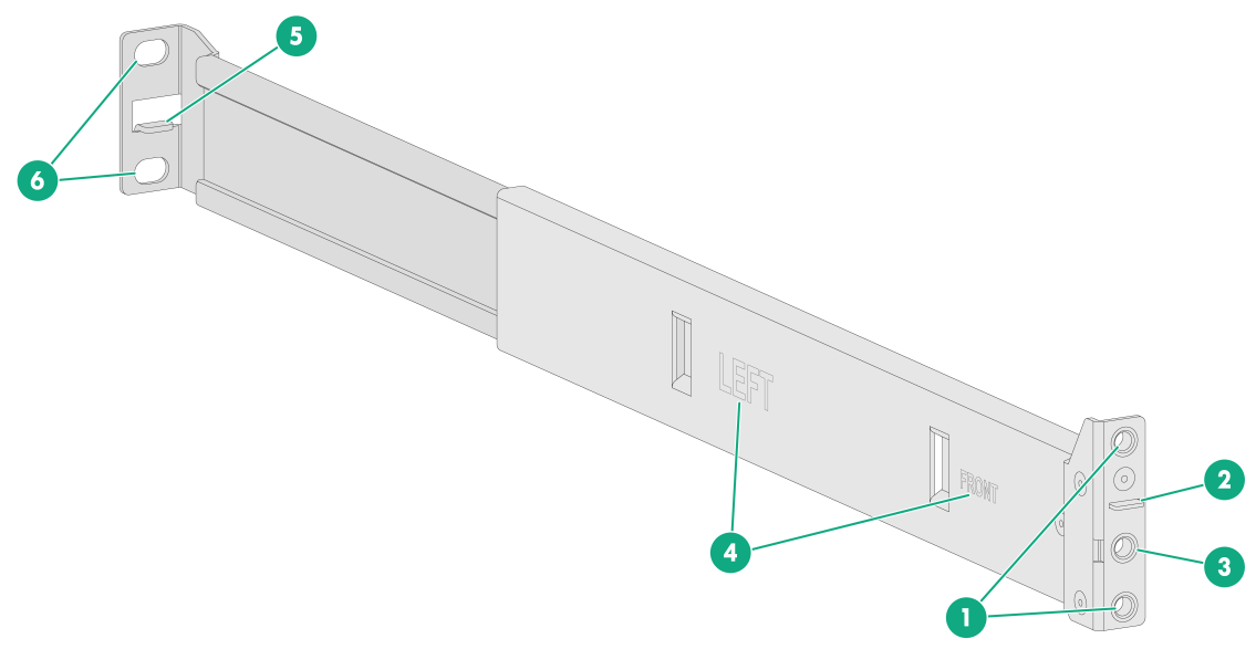
|
(1) Front mounting screw holes |
(2) Front mounting clip |
|
(3) Mounting bracket installation hole |
(4) Identification marks |
|
(5) Rear mounting clip |
(6) Rear mounting screw holes |
Figure2-4 Right outer rail
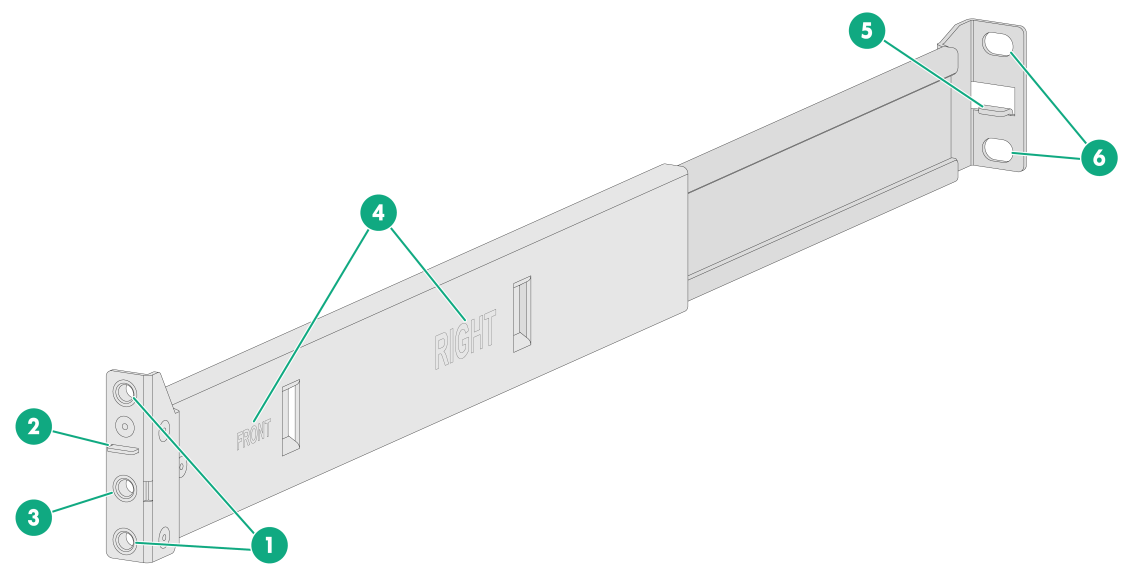
|
(1) Front mounting screw holes |
(2) Front mounting clip |
|
(3) Mounting bracket installation hole |
(4) Identification marks |
|
(5) Rear mounting clip |
(6) Rear mounting screw holes |
Figure2-5 Inner rail
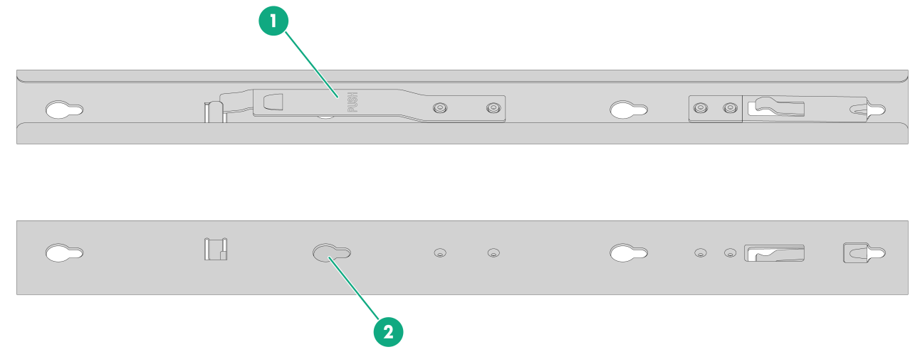
|
(1) Release tab |
(2) Keyhole slot |
Attaching inner rails to the device
1. Unpack the inner rails.
2. Pressing the release tab on the inner rail, extend each rail to its maximum length.
3. Attach an inner rail to the device.
|
|
IMPORTANT: For some devices, you must first remove the transport security screw before attaching inner rails to them. View the labels on the device carefully to identify the location of transport security screws. |
a. As shown by callout 1 in Figure2-6, align the four keyhole slots in the inner rail with the pegs on the chassis side panel and place the inner rail against the side panel.
b. As shown by callout 2 in Figure2-6, slide the rail toward the chassis rear to lock the rail in place on the pegs.
4. Repeat the same procedure to attach the other inner rail to the other side panel of the device.
Figure2-6 Attaching an inner rail to the device
|
|
NOTE: You must set the keyhole slots in the rails over all the four pegs on each side panel of the device. In Figure2-6, a peg is blocked by the release tab and only three pegs are displayed. |
Attaching outer rails to the rack
1. Identify the left and right outer rails.
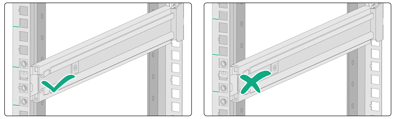
2. Determine and mark the outer rail installation position on the rack posts. Make sure the rails take a 1U of rack space at the same height of the rack posts.
Figure2-7 Correct and wrong installation positions
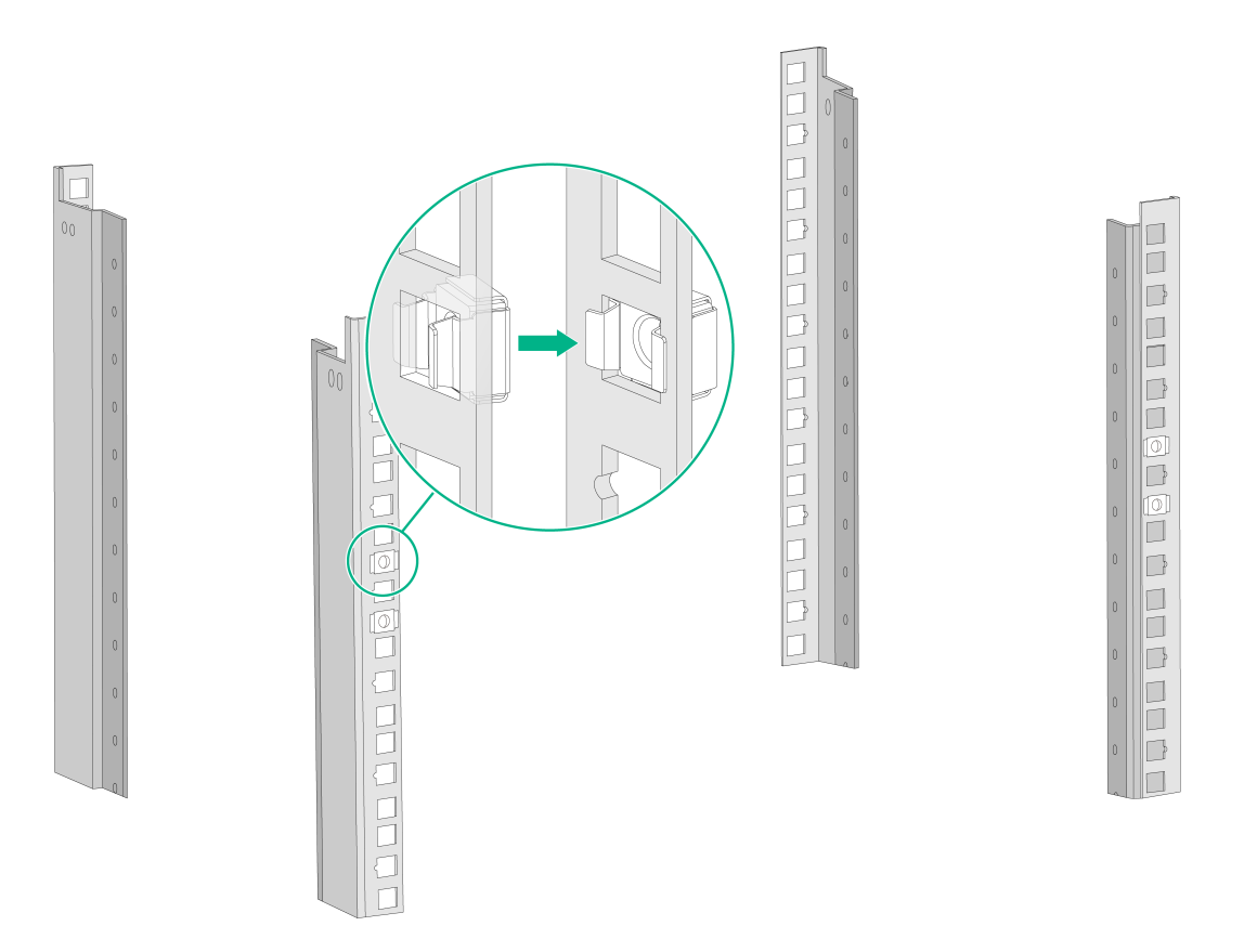
3. As shown in Figure2-8, install two M6 cage nuts at the marked positions on each rear rack post.
The front ends of the outer rails provide threaded screw holes. You are not required to install M6 cage nuts in these screw holes.
Figure2-8 Installing cage nuts
4. Attach an outer rail to the rack.
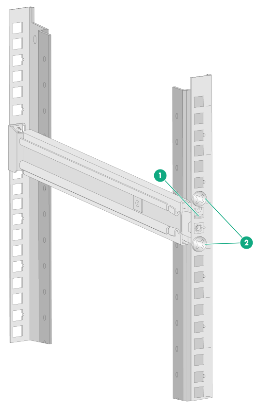
a. Attach the front end of the outer rail to the front rack post.
Align the screw holes in the front end of the outer rail with the marked square holes in the front rack post and insert the mounting clip into the square hole in the rack post, as shown by callout 1 in Figure2-9. Then use two M6 countersunk head screws to secure the front end of the rail to the rack post.
As a best practice, use a torque of 30 kgf·cm (2.94 Nm) to fasten the M6 countersunk head screws.
Figure2-9 Securing the front end of an outer rail to the rack
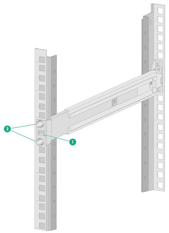
c. Adjust the length of the rail and attach the rear end of the outer rail to the rear rack post.
As shown by callout 1 in Figure2-10, align the screw holes in the rear end of the outer rail with the cage nuts in the rear rack post and insert the mounting clip into the square hole in the rack post. Then use two M6 pan-head screws to secure the rear end of the rail to the rear rack post.
As a best practice, use a torque of 30 kgf·cm (2.94 Nm) to fasten the M6 pan-head screws.
Figure2-10 Securing the rear end of an outer rail to the rack
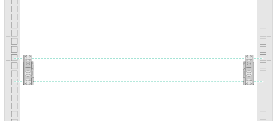
5. Repeat the same procedure to attach the other outer rail to the rack.
Make sure the left and right outer rails are installed at the same height so that the device can be installed safe and level on the rack.
Figure2-11 Left and right outer rails installed
Installing the device in the rack
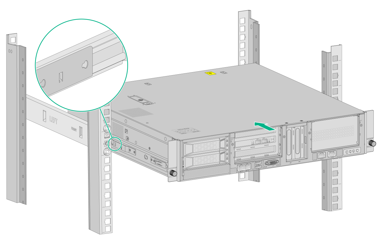
1. Slide the inner rails on the chassis into the outer rails on the rack posts and push the device into the rack.
|
|
WARNING! Be careful when you slide the device into the rack. Do not let the rails squeeze your fingers. |
Figure2-12 Mounting the device in the rack
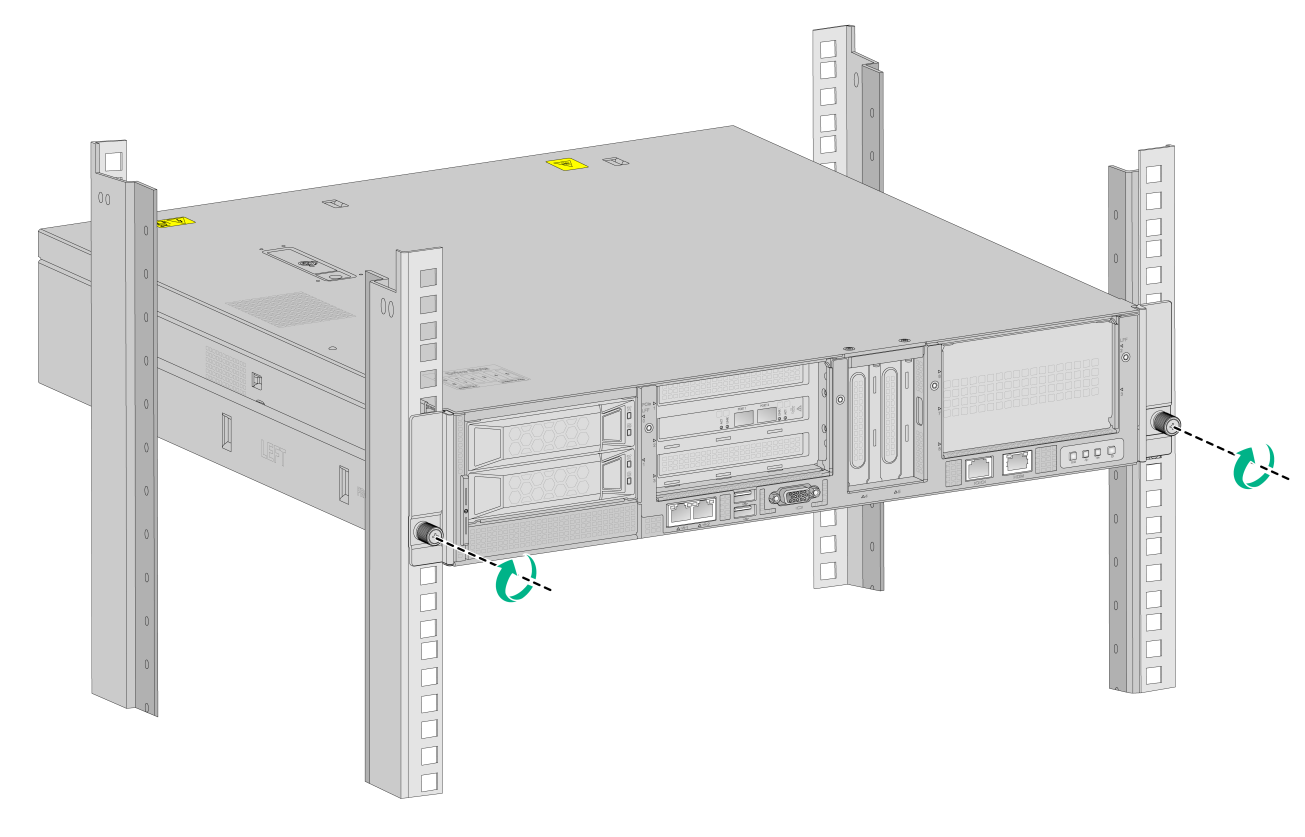
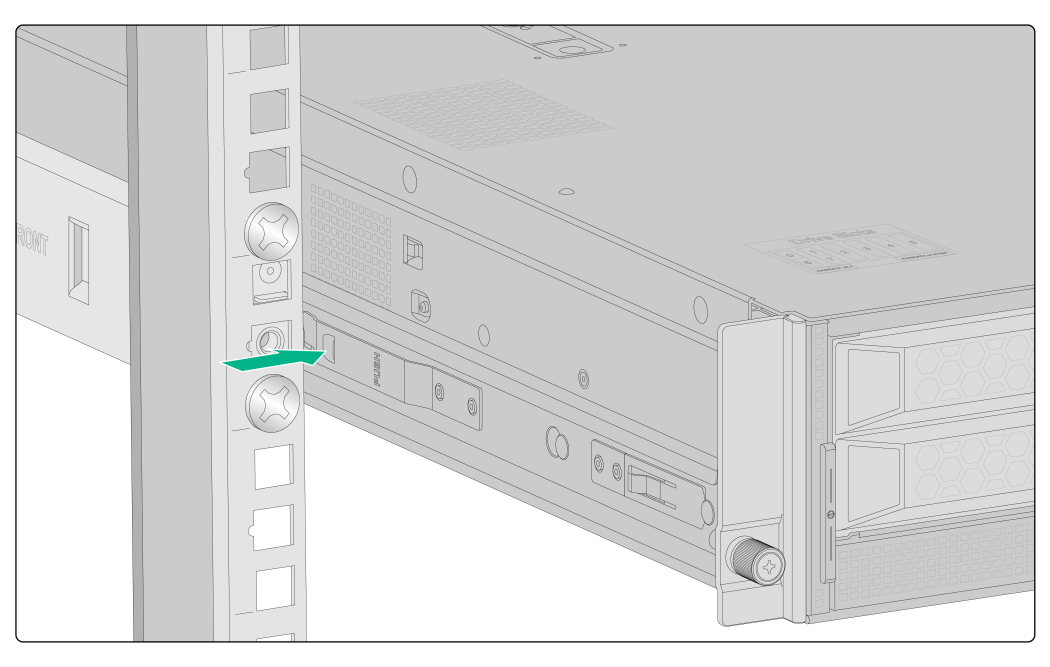
2. Place the mounting brackets of the device flush against the front rack posts. Then use captive screws to secure the mounting brackets to the front rack posts. As a best practice, use a torque of 30 kgf·cm (2.94 Nm) to fasten the captive screws.
Figure2-13 Securing the device to the rack
Installing a power supply
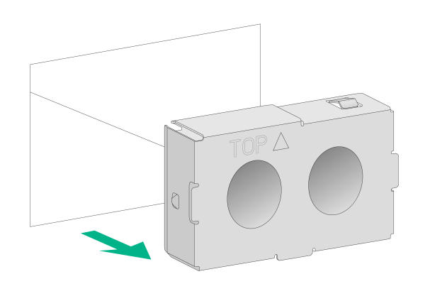
1. Remove the filler panel from the power supply slot.
Figure2-14 Removing the filler panel from the power supply slot
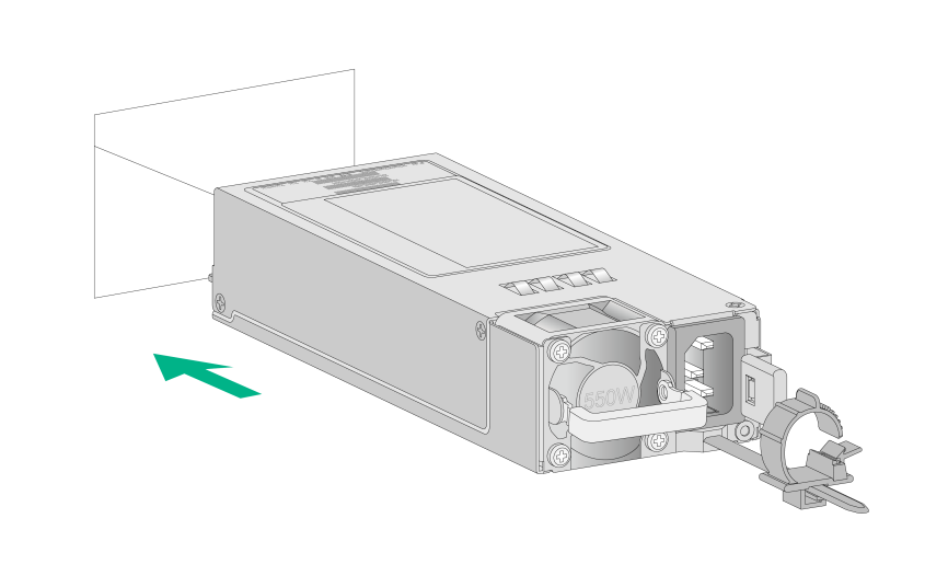
2. Push the power supply into the slot until it snaps into place.
Figure2-15 Installing the power supply
Connecting external cables
Cabling guidelines
|
|
WARNING! To avoid electric shock, fire, or damage to the equipment, do not connect communication equipment to RJ-45 Ethernet ports on the device. |
· For heat dissipation, make sure no cables block the inlet or outlet air vents of the device.
· To easily identify ports and connect/disconnect cables, make sure the cables do not cross.
· Label the cables for easy identification of the cables.
· Wrap unused cables onto an appropriate position on the rack.
Connecting a mouse, keyboard, and monitor
1. Connect one plug of a VGA cable to a VGA connector on the device, and fasten the screws on the plug.
Figure2-16 Connecting a VGA cable
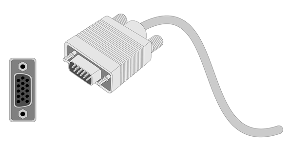
2. Connect the other plug of the VGA cable to the VGA connector on the monitor, and fasten the screws on the plug.
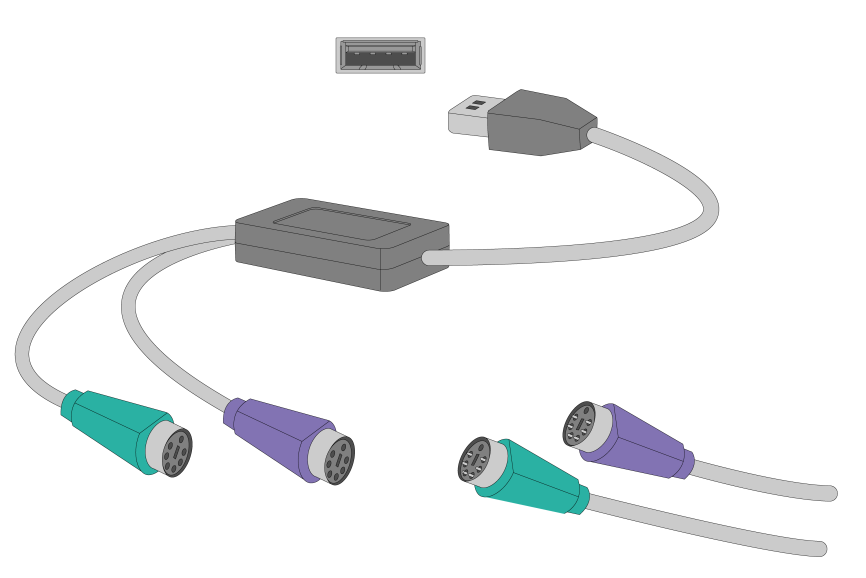
3. Connect the mouse and keyboard.
¡ For a USB mouse and keyboard, directly connect the USB connectors of the mouse and keyboard to the USB connectors on the device.
¡ For a PS2 mouse and keyboard, insert the USB connector of the USB-to-PS2 adapter to a USB connector on the device. Then, insert the PS2 connectors of the mouse and keyboard into the PS2 receptacles of the adapter.
Figure2-17 Connecting a PS2 mouse and keyboard by using a USB-to-PS2 adapter
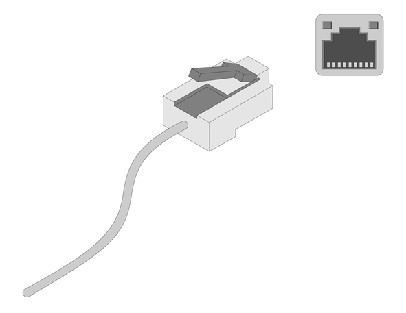
Connecting an Ethernet cable
To connect the device to the network, use one of the two Ethernet ports on the device front panel.
To log in to HDM from the Web interface, use the HDM dedicated network port or HDM shared network port (Ethernet port 1) on the device front panel. For the position of the ports, see "Chassis views."
Figure2-18 Connecting an Ethernet cable
Connecting a fiber port
|
|
CAUTION: · To connect a fiber port by using an optical fiber, first install a transceiver module in the port and then connect the optical fiber to the transceiver module. · Insert a dust cap into any open optical fiber connector and a dust plug into any open fiber port or transceiver module port to protect them from contamination and ESD damage. · Never bend an optical fiber excessively. The bend radius of an optical fiber must be not less than 100 mm (3.94 in). · Keep the fiber end clean. · Make sure the Tx and Rx ports on a transceiver module are connected to the Rx and Tx ports on the peer end, respectively. |
No transceiver modules are provided with the device. Purchase transceiver modules yourself as required. For transceiver module specifications, see "Appendix C Optional transceiver modules."
The fiber ports on the device support only LC connectors.
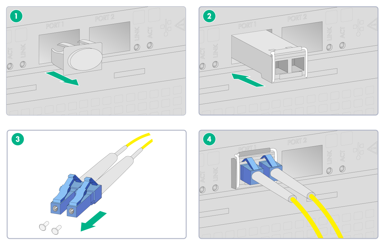
To connect an optical fiber for a fiber port:
1. Remove the dust plug from the fiber port.
2. Remove the dust cap from the transceiver module, and insert the transceiver module slowly into the port.
3. Remove the dust cap from the fiber connectors on the optical fiber.
4. Identify the Rx and Tx ports on the transceiver module. Use the optical fiber to connect the Rx port and Tx port on the transceiver module to the Tx port and Rx port on the peer end, respectively.
Figure2-19 Connecting an optical fiber
5. Examine the fiber port Link LED to verify that the port is operating correctly. For more information about the Link LED, see "Rear panel LEDs."
Connecting a USB device
USB devices are hot swappable.
To connect a USB device:
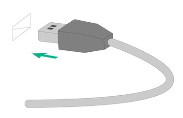
1. Connect the USB device to the USB connector, as shown in Figure2-20.
Figure2-20 Connecting a USB device to a USB connector
2. Verify that the device can identify the USB device.
If the device fails to identify the USB device, download and install the driver of the USB device. If the device still fails to identify the USB device after the driver is installed, replace the USB device.
Connecting the power cord
|
|
WARNING! To avoid damage to the equipment or even bodily injury, use the power cord shipped with the device. |
Before connecting the power cord, make sure the device and components are installed correctly.
To connect the power cord:
1. Open the latch on the tie mount of the cable clamp and slide the clamp backward.
2. Open the cable clamp, place the power cord through the opening in the cable clamp, and then close the cable clamp.
3. Insert the power cord connector into the receptacle on the power supply.
4. Slide the cable clamp forward until it is flush against the edge of the power cord connector.
5. Connect the other end of the power cord to the power supply system.
Figure2-21 Connecting the power cord
Removing the device from a rack
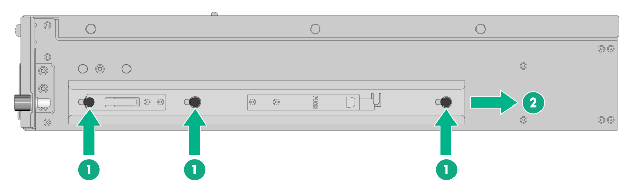
1. Power down the device. For more information, see "Powering off the device."
2. Disconnect all cables from the device.
3. Remove the device from the rack.
a. Use a screwdriver to loosen the captive screws on the mounting brackets. Then, slide the device out of the rack until it stops.
b. Supporting the bottom of the device and holding down the release tabs on the inner slides, pull the device all the way out of the rack.
Figure2-22 Pressing the release tab
4. Place the device on a clean, stable antistatic workbench or on the floor.
Removing a power supply
The power supplies are hot swappable. If two power supplies are installed and sufficient space is available for replacement, you can replace a power supply without powering off or removing the device from the rack.
To remove a power supply:
1. Power off the device. For more information, see "Powering off the device."
2. Remove the device from the rack. For more information, see "Removing the device from a rack."
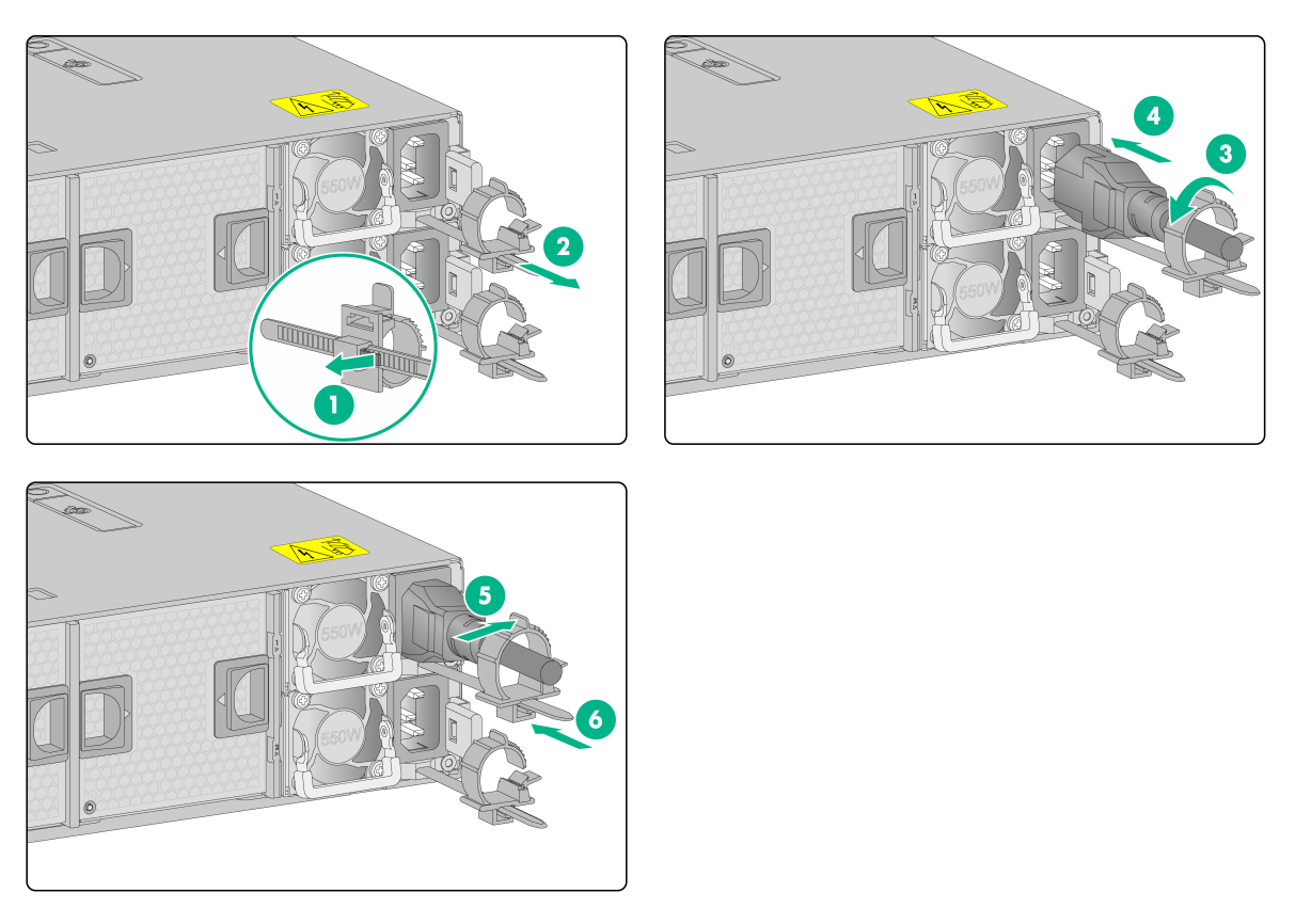
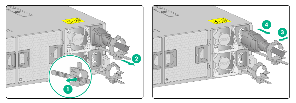
3. Remove the power cord from the power supply:
a. Open the latch on the tie mount of the cable clamp and slide the cable clamp outward.
b. Open the cable clamp and remove the power cord out of the clamp.
c. Disconnect the power cord.
Figure2-23 Removing the power cord
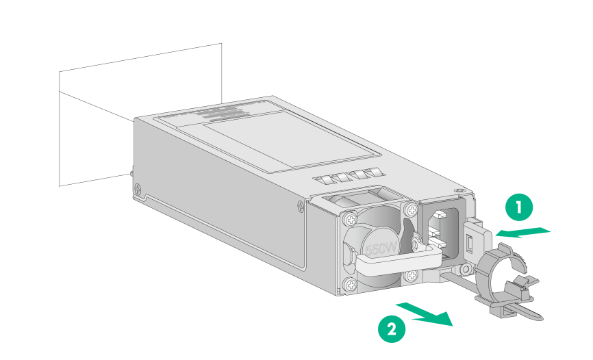
4. Press the retaining latch with your thumb and hold the power supply by its handle to release the power supply. Then pull the power supply slowly out of the slot, as shown in Figure2-24.
Figure2-24 Removing the power supply
3 Powering on, powering off, and rebooting the device
Important information
If the device is connected to external storage devices, make sure the device is the first device to power off and then the last device to power on. This restriction prevents the device from mistakenly identifying the external storage devices as faulty devices.
Powering on the device
Powering on the device by pressing the power on/standby button
Press the power on/standby button to power on the device.
The device exits standby mode and supplies power to the system. The system power LED changes from steady amber to flashing green and then to steady green. For information about the position of the system power LED, see "Front panel LEDs."
Powering on the device from the HDM Web interface
1. Log in to the HDM. For information about how to log in to HDM, see "Logging in to HDM from the Web interface."
2. From the navigation pane, select Power Manager > Power Control.
The power control configuration page opens.
3. Select Power on and then click Execute.
Powering on the device from the remote console interface
1. Log in to HDM. For information about how to log in to HDM, see "Logging in to HDM from the Web interface."
2. Log in to the remote console. For more information, see "Logging in to the remote console."
3. Click the ![]() button
at the top right corner of the page.
button
at the top right corner of the page.
Powering off the device
Guidelines
|
|
CAUTION: To avoid software system damage or service anomaly, do not power off the device. If you have to power off the device, do that from the WBC Monitoring Platform. For more information, see "Powering off the device from the WBC Monitoring Platform." |
Before powering off the device, you must complete the following tasks:
· Backup all critical data.
· Make sure all services have stopped or have been migrated to other devices.
Procedure
Powering off the device from its operating system
1. Connect a monitor, mouse, and keyboard to the device.
2. Shut down the operating system of the device.
3. Disconnect all power cords from the device.
Powering off the device by pressing the power on/standby button
1. Press and hold the power on/standby button until the system power LED turns into steady amber.
This method forces the device to enter standby mode without properly exiting applications and the operating system. If an application stops responding, you can use this method to force a shutdown.
2. Disconnect all power cords from the device.
Powering off the device from the HDM Web interface
1. Log in to HDM. For information about how to log in to HDM, see "Logging in to HDM from the Web interface."
2. From the navigation pane, select Power Manager > Power Control.
The power control configuration page opens.
3. Select Force power-off or Graceful power-off and then click Execute to put the device in standby mode.
4. Disconnect all power cords from the device.
Powering off the device from the remote console interface
1. Log in to HDM. For information about how to log in to HDM, see "Logging in to HDM from the Web interface."
2. Log in to a remote console. For more information, see "Logging in to the remote console."
3. Select Power from the menu and then click Force Power Off or Graceful Power Off.
4. Disconnect all power cords from the device.
Powering off the device from the WBC Monitoring Platform
1. Log in to the WBC Monitoring Platform. For information about how to log in to the WBC monitoring system, see "Logging in to the WBC Monitoring Platform."
2. Click Devices, and then click the ![]() button to the right side of Device Summary on
the Device Info tab.
button to the right side of Device Summary on
the Device Info tab.
3. Disconnect all power cords from the device.
Rebooting the device
Guidelines
|
|
CAUTION: To avoid software system damage or service anomaly, do not reboot the device forcibly. If you have to reboot the device, do that from the WBC Monitoring Platform as described in the following procedure. |
Before rebooting the device, you must complete the following tasks:
· Backup all critical data.
· Make sure all services have stopped or have been migrated to other devices.
Procedure
1. Log in to the WBC Monitoring Platform. For information about how to log in to the WBC monitoring system, see "Logging in to the WBC Monitoring Platform."
2. Click Devices, and then click the ![]() button to the right side of Device Summary on
the Device Info tab.
button to the right side of Device Summary on
the Device Info tab.
3. The device starts rebooting. The reboot process might take about 20 to 60 minutes. Avoid power interruption during this period.
After the device has rebooted, you can log into the device. For information about how to log in to the device, see "Logging in to the device."
4 Logging in to the device
|
|
IMPORTANT: The information in this document might be slightly different depending on the software or hardware version of the device. |
The device uses the CentOS operating system and contains the following management components:
· Cloud server (Oasis platform) —Allows users to monitor network conditions, manage the device, and operate O2O services online.
· License server—Manages licenses in a unified way and provides license server hot backup to achieve high service availability. It can simplify license management and control dynamic service licensing to solve licensing interruption caused by single-point failure.
· Access controller (AC)—Controls wireless data forwarding and centrally manages access points (APs).
· Device management—Provides device network configuration, system update, backup and restore, and real-time monitoring on device health state and CPU usage.
Restrictions and guidelines
· As a best practice, use one of the following browsers to access the Web interface:
¡ Chrome 48 or higher.
¡ Internet Explorer 11.836.18362.0 or higher in the Windows 10 system.
¡ Firefox 50 or higher.
· Make sure the browser allows third-party cookies and is enabled with Active Scripting (or JavaScript).
· If an Internet Explorer is used, make sure the following functions are enabled:
¡ Script ActiveX controls marked safe for scripting.
¡ Run ActiveX controls and plugins.
· After software update, first clear cache in the browser and then log in to the Web interface as a best practice.
· Make sure the resolution ratio of the PC (desktop, laptop, or tablet PC) is 1024 × 768 or higher.
Flowchart for logging in to the device
The device supports the following login methods:
· Logging in to the device from HDM
· Logging in to the device from the WBC Monitoring Platform
· Logging in to the device from a local PC
Use the following flowchart to determine the optimal device login method.
Figure4-1 Device login flowchart
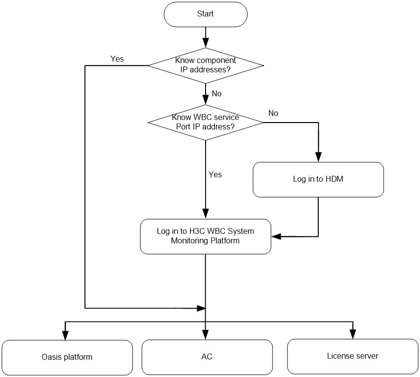
Logging in to the device from HDM
If you cannot obtain the IP addresses of the Oasis Platform, AC, license server, and WBC Monitoring Platform use this method to log in to the device.
Logging in to HDM from the Web interface
Hardware Device Management (HDM) is a remote server management system. HDM enables easy server configuration, server component information retrieval, operating health status monitoring, and remote control.
Preparing for an HDM login
Before logging in to HDM, perform the following tasks:
· Connect the HDM shared or dedicated port on the server to the network.
¡ The HDM shared network port transmits HDM management traffic and server data traffic simultaneously.
¡ The HDM dedicated network port transmits only HDM management traffic.
· Obtain HDM management IP address and user account information. For the first login, use the default settings in Table4-1.
Table4-1 Default HDM login settings
|
Item |
Default setting |
|
IP address |
· HDM shared network port: DHCP assigned IP address · HDM dedicated network port: 192.168.1.2/24 |
|
Username |
admin |
|
Password (case-sensitive) |
|
|
Domain name |
You can obtain the domain name from the label at the lower left corner on the chassis hood. |
Procedure
1. Launch the browser, and enter the HDM management IP address in the https://hdm_ip_address format in the address bar. This example uses a Microsoft Internet Explorer browser and an HDM management IP address of 192.168.1.2.
2. On the security certificate page that opens, click the Proceed to 192.168.1.2 (unsafe) link.
3. (Optional.) Click Select language at the bottom of the page to select the interface language. HDM supports both simplified Chinese and English.
4. On the login page, enter the username and password, and then click Sign in.
If this is the first login, enter the default username (admin) and password (Password@_).
Figure4-2 HDM login page

Logging in to the remote console
You can manage the device and install an operating system (OS) from a remote console.
HDM supports a maximum of four remote control sessions. If you establish the first session, you are the primary user. All subsequent remote console users are secondary users and must obtain access permissions from the primary user.
Remote consoles include KVM, H5 KVM, and VNC remote consoles. In the current software version, HDM supports both KVM and H5 KVM remote consoles.
· To use KVM, you must first set up the OS environment. The environment setup configuration varies by OS type.
· To use VNC, client installation is required for VNC.
· To use H5 KVM, no OS environment or client installation is required.
Setting up the Windows environment for KVM
As a best practice, use Zulu OpenJDK 8 and IcedTea-Web 1.7.1 to run KVM.
You can obtain the installation packages at the following websites:
· Zulu OpenJDK: https://www.azul.com/downloads/zulu/
· IcedTea-Web: http://icedtea.wildebeest.org/download/icedtea-web-binaries/
To set up the Windows environment for KVM:
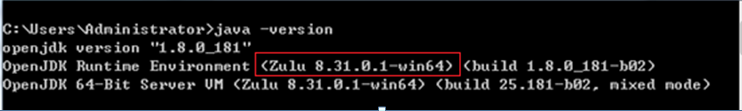
1. Install the OpenJDK Java environment:
a. Obtain the msi. installation file for Zulu OpenJDK and install OpenJDK with the default settings.
b. Verify the version of OpenJDK.
Figure4-3 Verifying the version of OpenJDK
2. Install the IcedTea-Web plugin:
Open the .msi installation file of the target version for the plugin, and install the plugin with the default settings.
3. Run HDM KVM:
a. Access the installation directory of the IcedTea-Web plugin. This example uses directory C:\Program Files\IcedTeaWeb\WebStart\bin.
b. Open the CLI in the directory and execute the javaws jnlp_directory command. The jnlp_directory argument represents the directory of the downloaded .jnlp file.
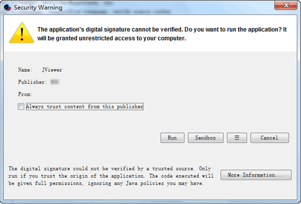
c. In the dialog box that opens, click Run.
Figure4-4 Command execution
4. The KVM login window opens. You can enter password admin.Default.0506 to access KVM.
Setting up the Linux environment
As a best practice, use Zulu OpenJDK 8 and IcedTea-Web to run HDM KVM.
You can obtain the installation packages at the following websites:
· Zulu OpenJDK: https://www.azul.com/downloads/zulu/
· IcedTea-Web: http://icedtea.wildebeest.org/download/source/
To set up the Linux environment for KVM:
1. Install the IcedTea-Web plugin:
Use the yum install filename command to install the plugin. The filename argument represents the name of the installation package. In this example, the package name is icedtea-web.x86_64.
Figure4-5 Installing the IcedTea-Web plugin
![]()
2. Install the OpenJDK Java environment:
a. Use either of the following methods to install OpenJDK:
- If you downloaded the .rpm installation package, execute the rpm –ivh xxx.rpm command. The xxx.rpm argument represents the package name.
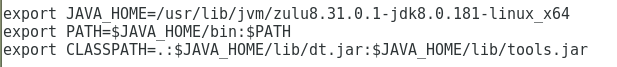
- If you downloaded the tar.gz package, decompress the package to the /usr/lib/jvm directory, and then append the following commands to the end of the /etc/profile file:
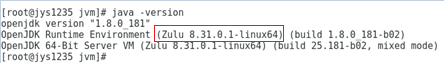
b. Verify that OpenJDK 8 has been installed.
Figure4-6 Verifying OpenJDK version
3. Run HDM KVM:
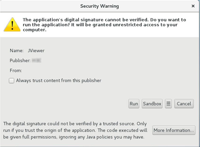
Double-click the downloaded KVM.jnlp file, and then click Run in the dialog box that opens.
Figure4-7 Running the HDM KVM
4. The KVM login window opens. You can enter password admin.Default.0506 to access KVM.
Launching a KVM or H5 KVM remote console
Restrictions and guidelines
Do not use KVM and H5 KVM at the same time or start the remote console in multiple browsers on one PC.
The dedicated KVM and H5 KVM modes are available only for HDM-1.30.08 or later.
The unencrypted H5 KVM modes are available only for HDM-1.30.09 or later.
For security purposes, grant full permission to a trustworthy secondary user when you close the remote console session as the primary user.
Granting full permission to a secondary user removes the full permission from the primary user. Then, the primary user has only the read-only permission.
The primary user can grant full permission to any secondary user when closing the KVM window. If the primary user does not grant full permission in 10 seconds, the permissions of secondary users remain unchanged.
The UID LED of the server flashes if a remote console is active.
Prerequisites
Before you can launch a remote control console, you must perform the following tasks:
· Make sure your user account has the remote control privilege. If you do not have the remote control privilege, contact the administrator.
· To launch the KVM console, make sure your user account has the KVM extended privilege. To launch the H5 KVM console, make sure your account has the Web and KVM extended privileges. If you do not have the Web or KVM privilege, contact the administrator.
Procedure
1. In the navigation pane, select Remote Services > Remote Console, as shown in Figure4-8.
Figure4-8 Entering remote console page
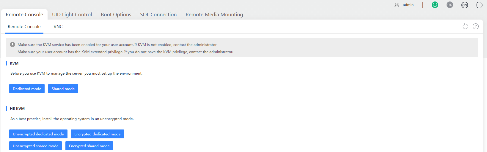
2. In the KVM or H5 KVM section, click a launch mode. This section launches an H5 KVM remote console.
Encrypted modes transmit encrypted data and provide better security performance. Unencrypted modes transmit unencrypted data and provide higher transmission speed.
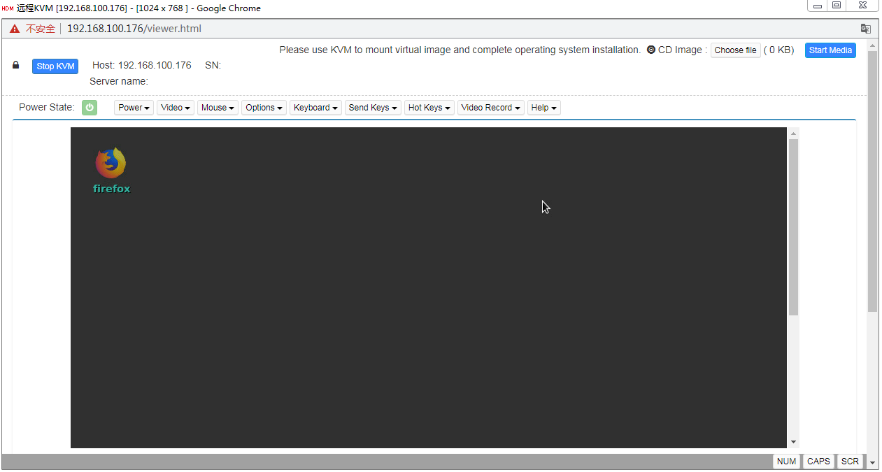
The remote console sign-in page opens.
Figure4-9 Remote console sign-in page
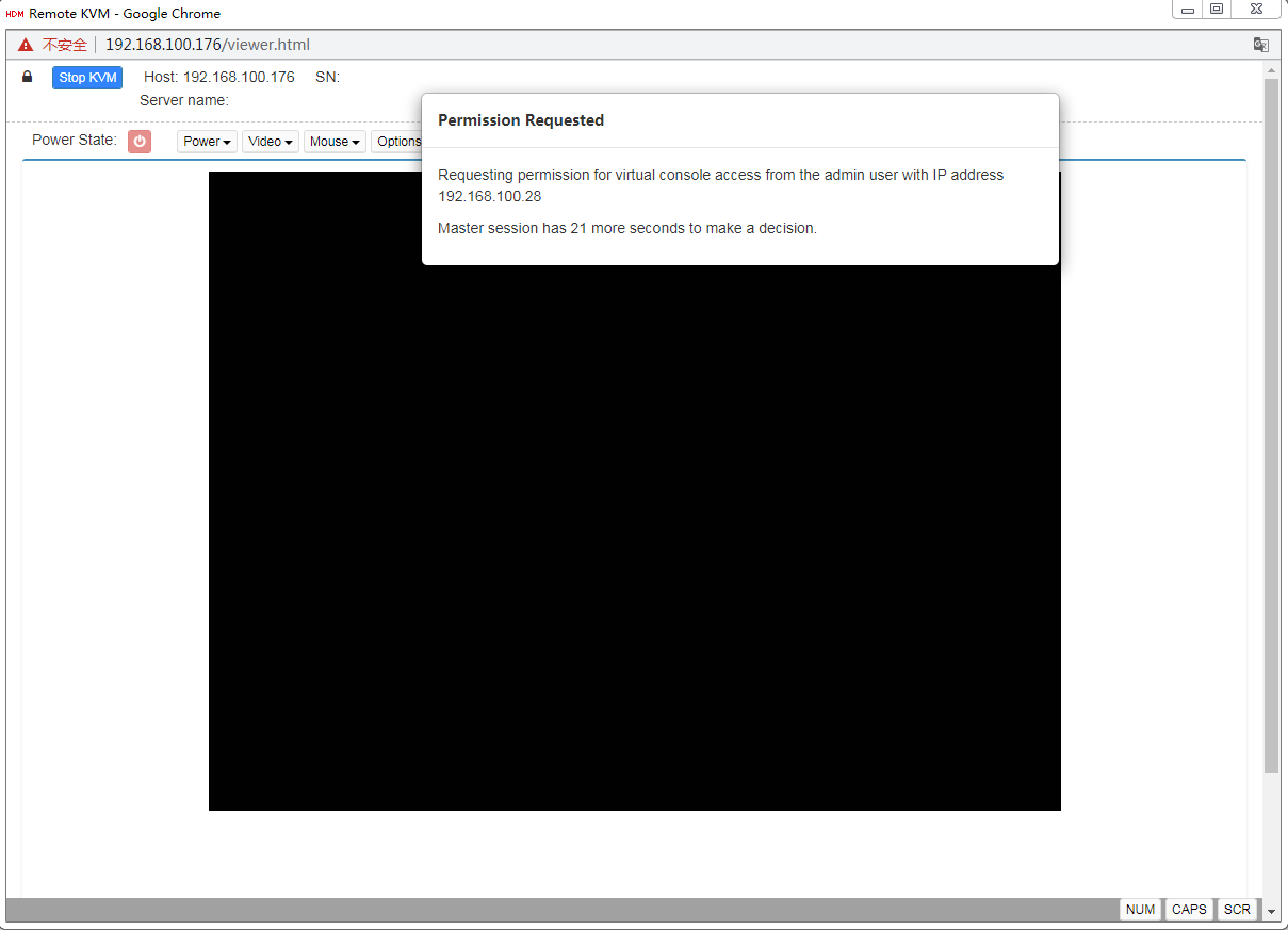
3. For a shared mode, wait for the access authorization from the primary user if you are not the first access user, as shown in Figure4-10.
Figure4-10 Waiting for remote console access authorization
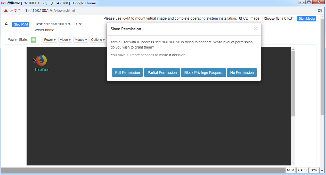
If you are the primary user, you might need to grant access permissions to other users, as shown in Figure4-11.
Figure4-11 Authorizing remote console access
Parameters
· Dedicated mode: Includes Encrypted dedicated mode and Unencrypted dedicated mode. A dedicated mode allows for only one remote console session and grants the user with the full access permission. You can launch the remote console successfully in dedicated mode only if no other user is using the remote console. In the current software version, KVM supports only unencrypted dedicated mode.
· Shared mode: Includes Encrypted shared mode and Unencrypted shared mode. A shared mode allows for a primary session and multiple secondary sessions. If you are the first access user, the system assigns you with the full access permission. If you are a secondary user, the granted permission is decided by the primary user as follows:
¡ If you are granted full access permission, you can display information and configure the server.
¡ If you are granted read-only permission, you can only view videos and screenshots, and record videos. You cannot perform any configuration tasks.
¡ If your access is denied, the KVM window closes.
¡ If the primary user does not respond in 30 seconds, you are granted read-only permission.
Logging in to the WBC Monitoring Platform
1. Open the browser to access the WBC Monitoring Platform.
Figure4-12 WBC Monitoring Platform
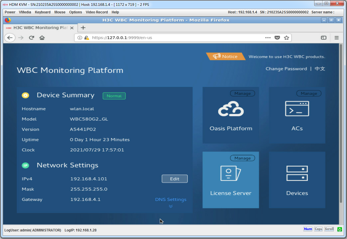
2. (Optional.) Select the interface language. WBC Monitoring Platform supports both simplified Chinese and English. You can click Change Password to change the login password.
3. Click Oasis Platform, ACs, and License server to access the Oasis platform, AC, and license server Web interface, respectively.
The Oasis platform Web interface, AC Web interface, and license server Web interface are as shown in Figure4-13, Figure4-14, and Figure4-15.
Figure4-13 Oasis platform Web interface
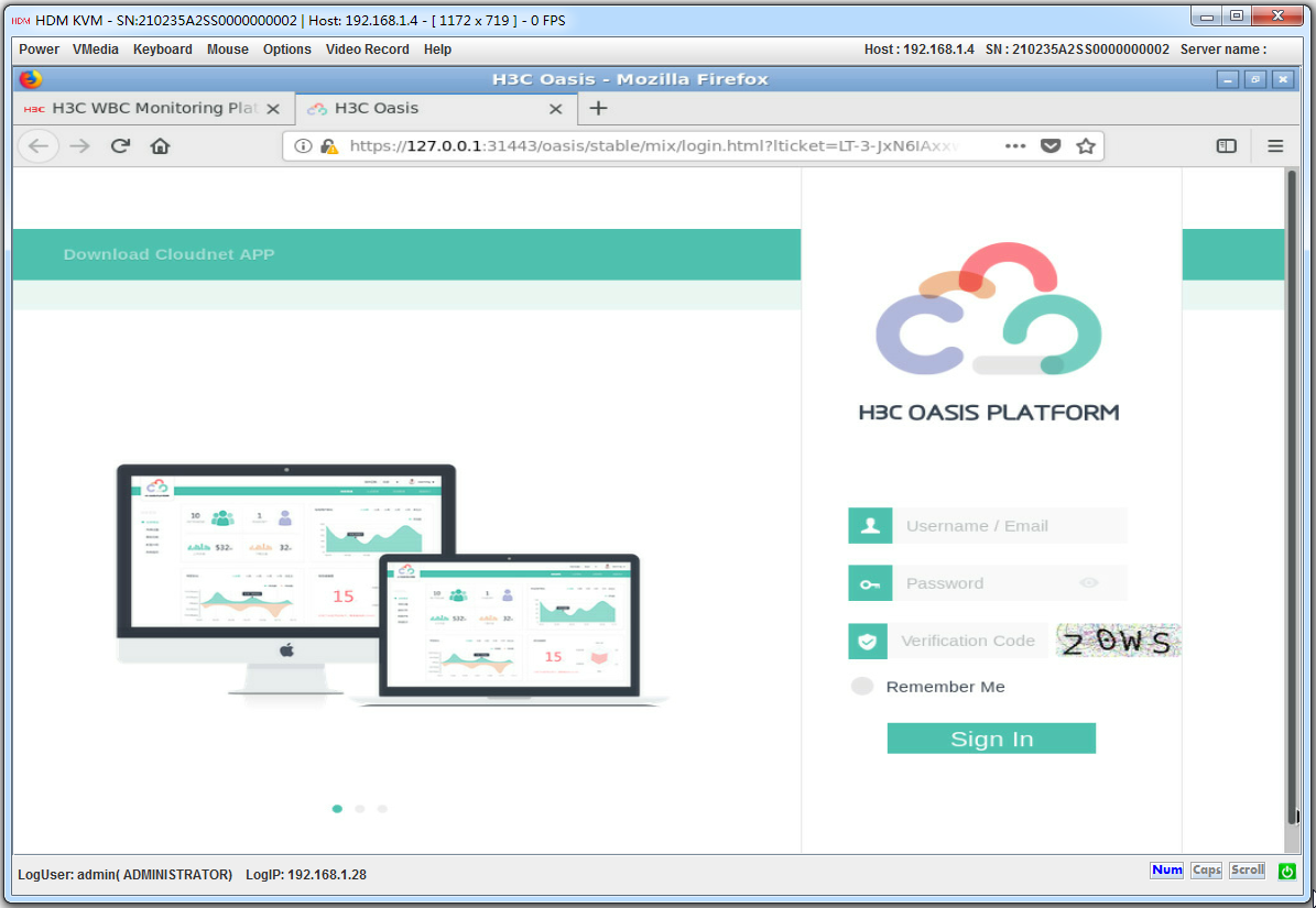
Figure4-14 AC Web interface
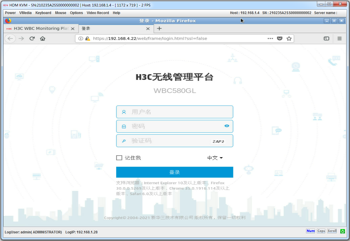
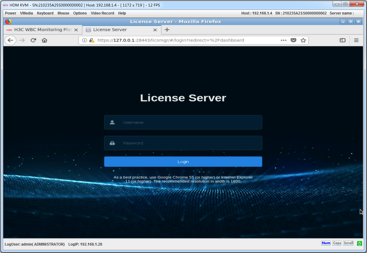
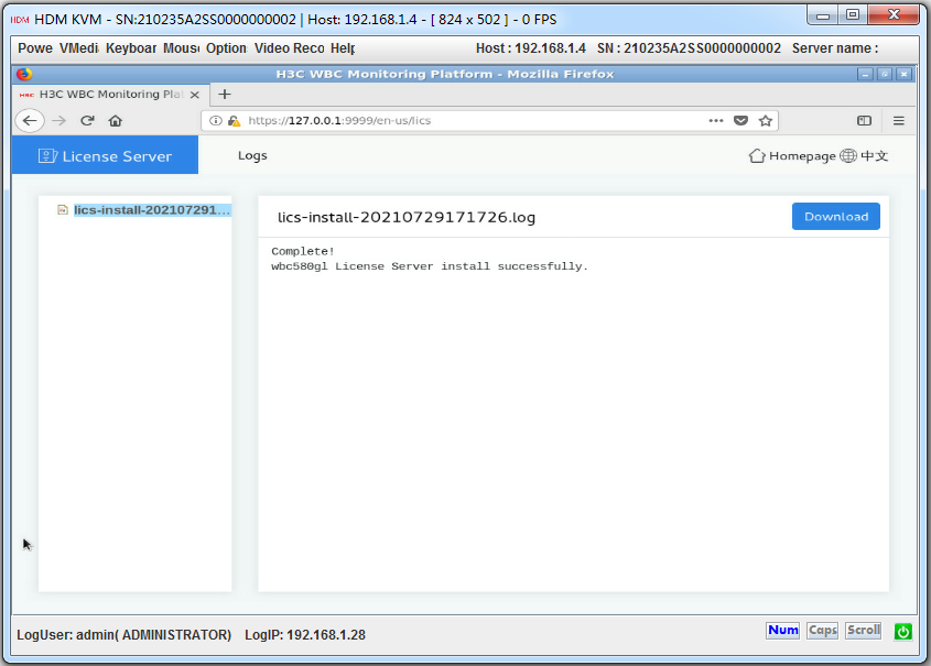
Figure4-15 License server Web interface
4. Click Manage at the right corner of the Oasis Platform, ACs, or License Server icon to access the O&M page.
The Oasis platform O&M page, AC O&M page, and license server O&M page are as shown in Figure4-16, Figure4-17, and Figure4-18.
Figure4-16 Oasis platform O&M page
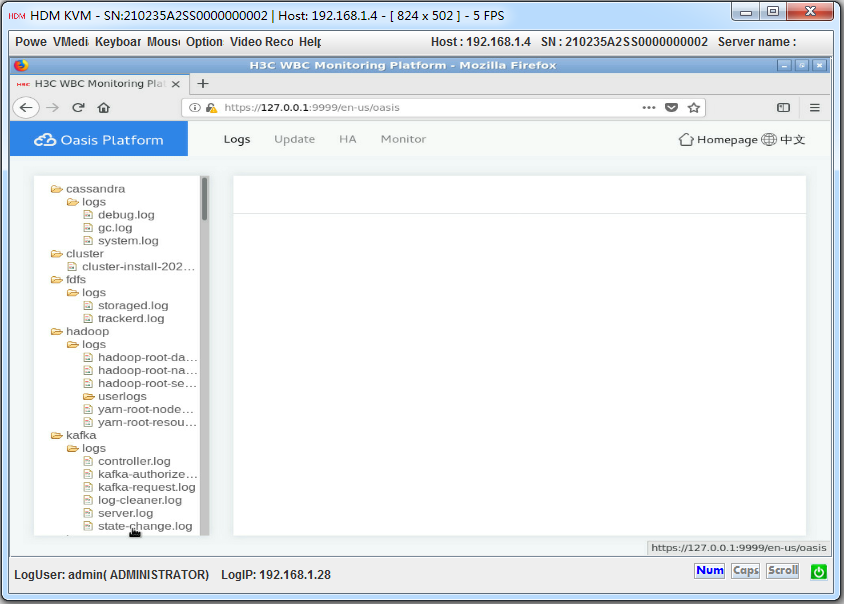
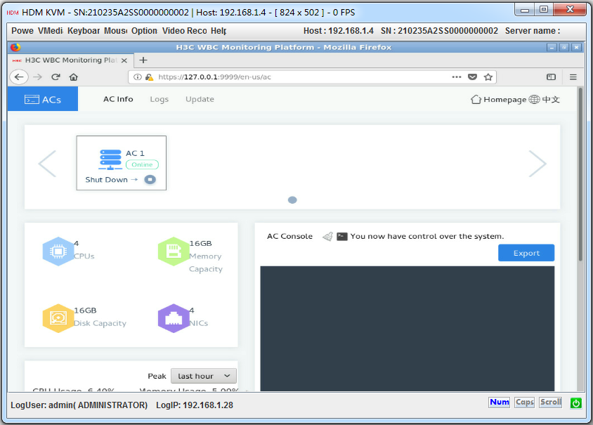
Figure4-18 license server O&M page
Logging in to the device from the WBC Monitoring Platform
If you can obtain only the URL of the WBC Monitoring Platform, use this method to log in to the device.
In the Internet Explorer browser, enter the complete URL of the WBC Monitoring Platform in the format of https://IP:Port/zh-cn/login.
To log in to the device from the WBC Monitoring Platform:
1. Launch the browser, and enter default URL https://192.168.0.101:9999 in the address bar. This example uses a Microsoft Internet Explorer browser and the default URL.
Figure4-19 WBC Monitoring Platform login page

2. Enter the username and password, and then click Log In.
If this is the first login, enter the default username (admin) and password (admin.Default.0506).
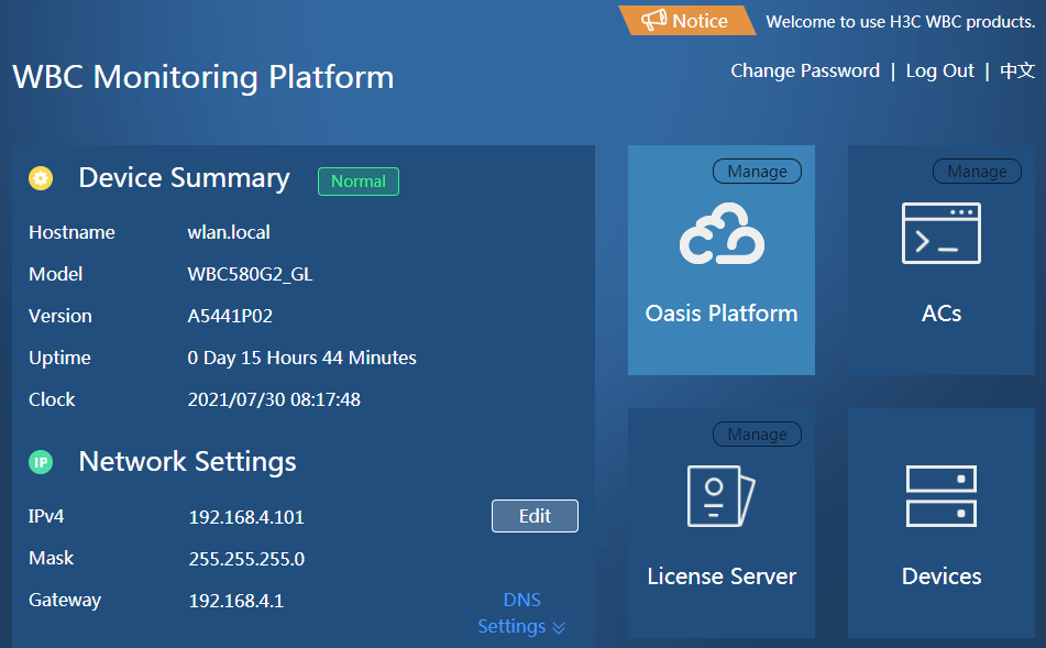
Figure4-20 WBC Monitoring Platform home page
3. Click Oasis Platform, ACs, and License server to access the Oasis platform, AC, and license server Web interface, respectively.
The Oasis platform Web interface, AC Web interface, and license server Web interface are as shown in Figure4-13, Figure4-14, and Figure4-15.
4. Click Manage at the right corner of the Oasis Platform, ACs, or License Server icon to access the O&M page.
The Oasis platform O&M page, AC O&M page, and license server O&M page are as shown in Figure4-16, Figure4-17, and Figure4-18.
Logging in to the device from a local PC
If you can obtain the IP addresses of the Oasis platform, AC, and license server, use this method to log in to the device.
Logging in to the Oasis platform from the local PC
1. Connect the PC to the device.
2. Launch the browser, and enter https://192.168.0.101:31443 in the address bar. This example uses a Microsoft Internet Explorer browser and the default Oasis platform IP address.
3. On the security certificate page that opens, click the Proceed to 192.168.0.101 (unsafe) link.
4. On the login page, enter the username and password, and then click Sign In.
If this is the first login, enter the default username (oasis_root) and password (oasis_root123456).
Figure4-21 Oasis platform login page

Logging in to the AC
|
|
IMPORTANT: By default, AC is enabled. To disable AC, see "Managing the AC." |
The factory-configured VLAN-interface 1 of the AC obtains an IP address through the DHCP protocol. To enable the AC to obtain an IP address through DHCP, make sure the local PC and AC are in the same subnet. If IP address acquisition through DHCP fails, VLAN-interface 1 of the AC uses the default IP address 192.168.0.100.
You can also log in to the device from HDM or from the WBC Monitoring Platform to obtain the current IP address of the AC. For more information, see "Logging in to the device from HDM" or "Logging in to the WBC Monitoring Platform."
Logging in to the AC from the CLI
Use Telnet to log in to the AC from the CLI.
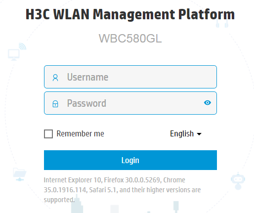
Logging in to the AC from the Web interface
1. Connect the PC to the device.
2. Launch the browser, and enter the AC IP address in the https://ip_address format in the address bar. This example uses a Microsoft Internet Explorer browser and an AC IP address of 192.168.100.155.
3. On the security certificate page that opens, click the Proceed to 192.168.100.155 (unsafe) link.
4. On the login page, enter the username and password, and then click Login.
If this is the first login, enter the default username (admin) and password (admin).
Figure4-22 AC Web interface login page
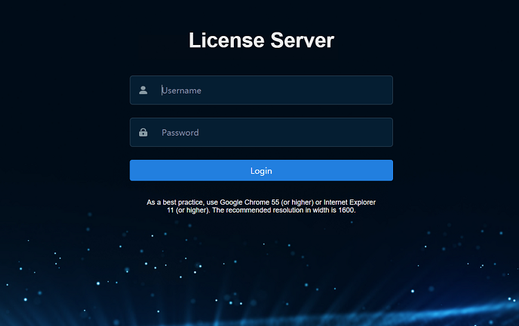
Logging in to the license server
1. Connect the PC to the device.
2. Launch the browser, and enter default license server IP address https://192.168.0.101:28443/licsmger in the address bar. This example uses a Microsoft Internet Explorer browser and the default license server IP address.
3. On the security certificate page that opens, click the Proceed to 192.168.0.101 (unsafe) link.
4. On the login page, enter the username and password, and then click Login.
If this is the first login, enter the default username (admin) and password (admin@123).
Figure4-23 License server login page
Managing the Oasis platform
1. Click Manage at the right corner of the Oasis Platform icon on the WBC Monitoring Platform to access the O&M page.
The Oasis platform O&M page is as shown in Figure4-24.
Figure4-24 Oasis platform O&M homepage
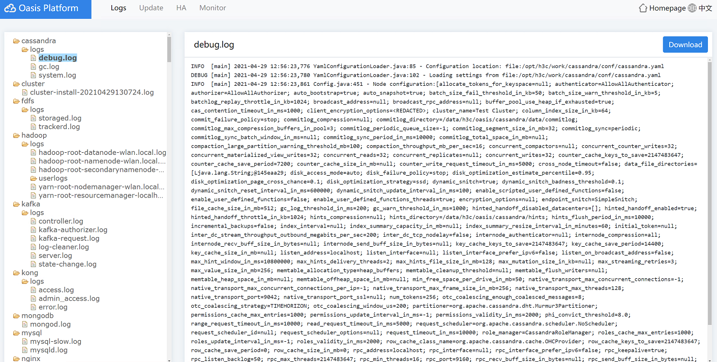
2. Click the Logs tab, you can view the detailed logs and perform the following tasks:
¡ To delete a log file, you can right-click a log folder name and select Delete.
¡ To download logs, you can right-click a log folder name and select Download, or click Download in the right corner of the page.
3. Click the Update tab to update the Oasis platform version.
Figure4-25 Oasis platform update page
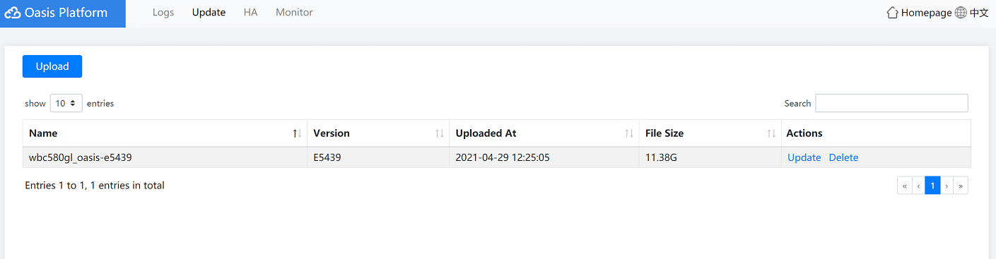
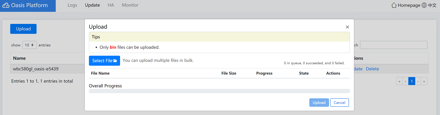
a. (Optional.) Click Upload. In the dialog box that opens, click Select File, select a file for upload, and then click Upload. After the file is uploaded to the Oasis platform, close the dialog box.
Figure4-26 Uploading a file
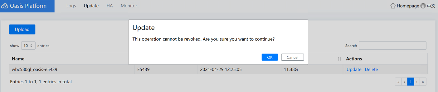
b. Click Update in the Actions column. In the dialog box that opens, click OK.
Figure4-27 Updating the Oasis platform version
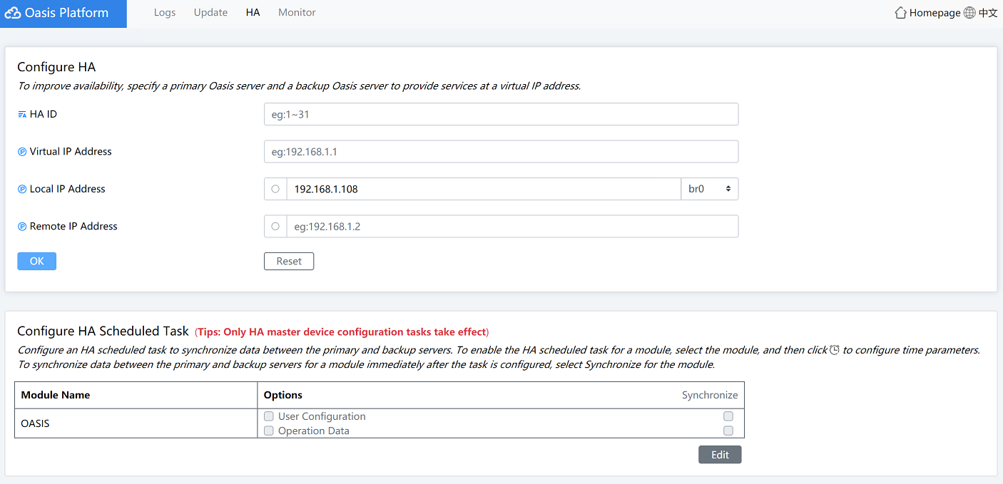
4. Click the HA tab to configure two devices to back up each other to ensure service continuity.
In the Configure HA area, you can configure the following parameters:
¡ HA ID—The HA ID must be unique in the Layer 2 network. The HA ID must be an integer in the range of 1 to 31.
¡ Virtual IP Address—The virtual IP address is used for the unified management of local and remote devices.
- Local IP Address—IP address of the local device.
¡ Remote IP Address—IP address of the remote device.
In the Configure HA Scheduled Task area, you can back up the device data of the current day. The device supports 30 data backup tasks. When the 31st data backup task triggers, the first backup data will be overwritten.
Figure4-28 Oasis platform HA page
a. Click Edit.
b. To configure an HA scheduled task, click the
![]() icon to configure the backup interval and
then click OK. The local device will back up the data to the remote device
according to the specified backup interval.
icon to configure the backup interval and
then click OK. The local device will back up the data to the remote device
according to the specified backup interval.
c. To configure an immediate HA task, select Synchronize. Thus, the local device will back up the data to the remote device immediately.
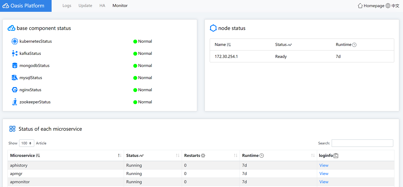
5. Click the Monitor tab to view the component status, node status, and microservice status.
Figure4-29 Oasis platform monitor page
Managing the AC
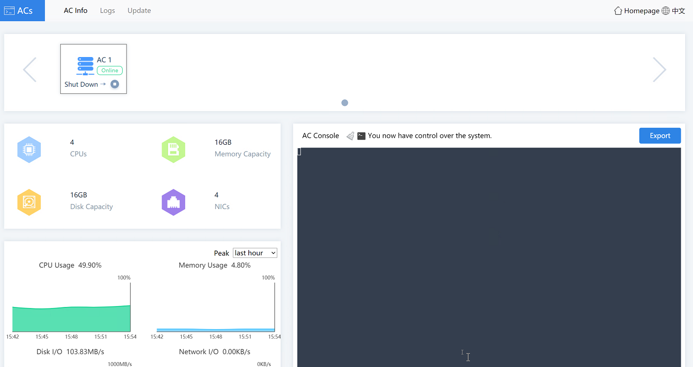
1. Click Manage at the right corner of the ACs icon on the WBC Monitoring Platform to access the O&M page.
The AC O&M page is as shown in Figure4-30.
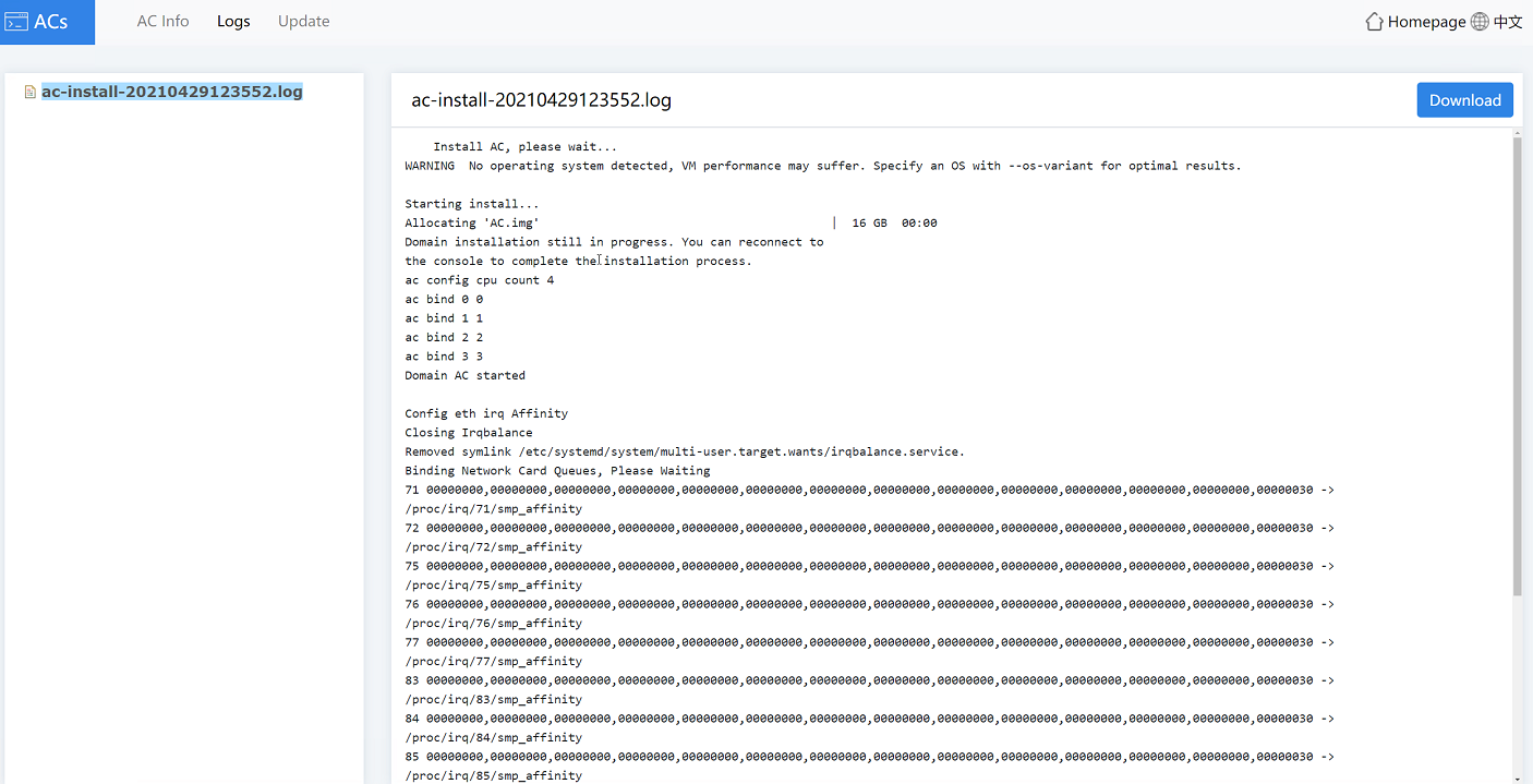
2. Click the Logs tab, you can view the detailed logs and perform the following tasks:
¡ To delete a log file, you can right-click a log folder name and select Delete.
¡ To download logs, you can right-click a log folder name and select Download, or click Download in the right corner of the page.
Figure4-31 AC logs page
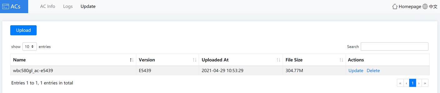
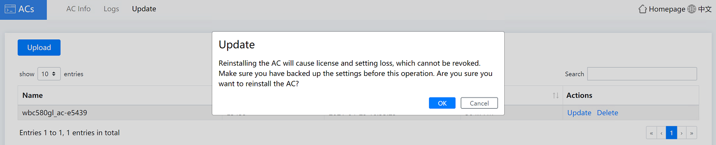
3. Click the Update tab to update the AC version.
|
|
IMPORTANT: To avoid AC license loss or AC configuration loss during the update, back up AC license and configuration in advance. |
Figure4-32 AC update page
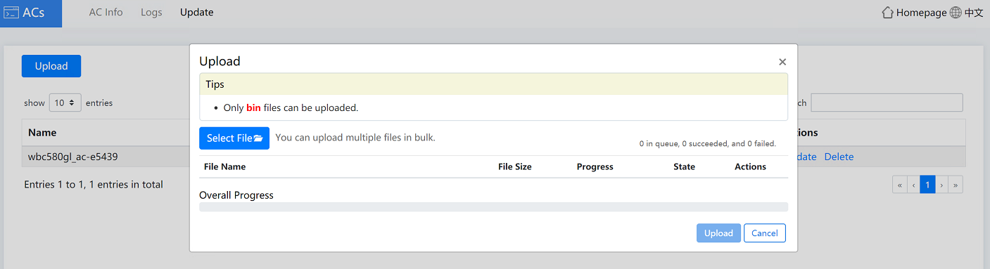
a. (Optional.) Click Upload. In the dialog box that opens, click Select File, select a file for upload, and then click Upload. After the file is uploaded to the AC, close the dialog box.
Figure4-33 Uploading a file
b. Click Update in the Actions column. In the dialog box that opens, click OK.
Figure4-34 Updating the AC version
Managing the license server
1. Click Manage at the right corner of the License Server icon on the WBC Monitoring Platform to access the O&M page.
The license server O&M page is as shown in Figure4-35.
Figure4-35 License server O&M homepage

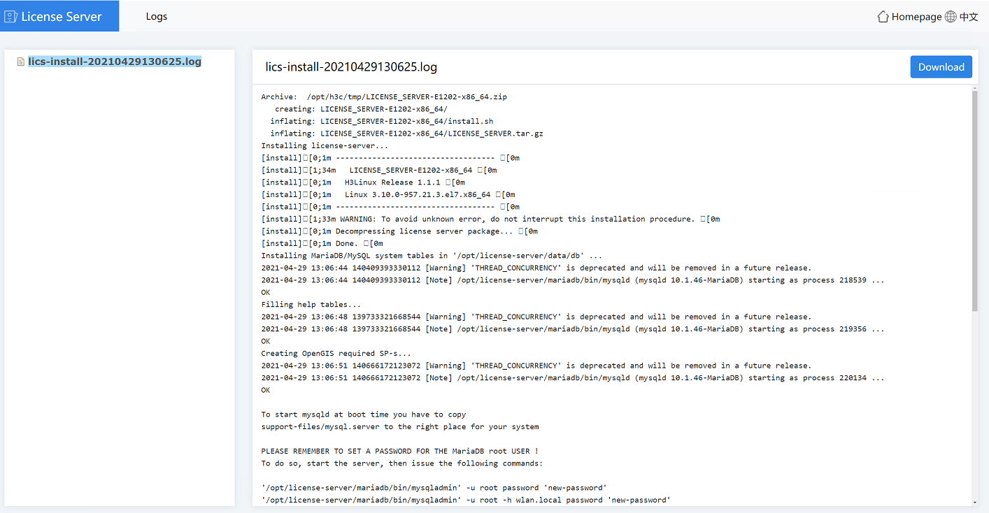
2. Click the Logs tab, you can view the detailed logs and perform the following tasks:
¡ To delete a log file, you can right-click a log folder name and select Delete.
¡ To download logs, you can right-click a log folder name and select Download, or click Download in the right corner of the page.
Figure4-36 License server logs page
Managing the device
On the Devices page, you can view device information, print logs, update device version, back up or rollback device configuration, and configure security.
To manage the device:
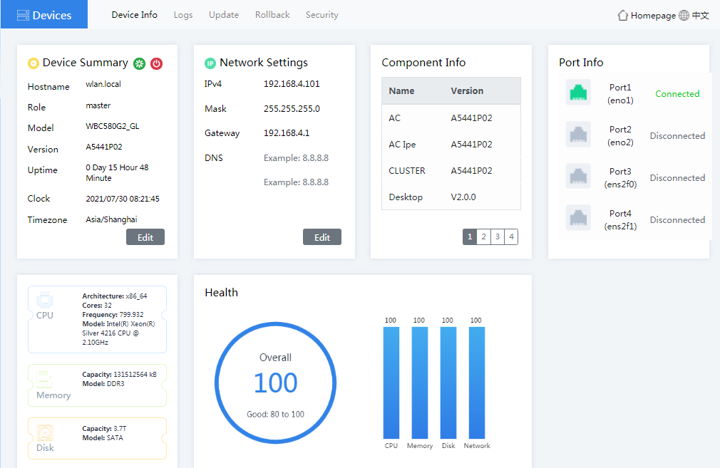
1. Click Devices on the WBC Monitoring Platform to access the devices page. As shown in Figure4-37, you can configure the following parameters:
¡ Device Summary—View hostname, role, model, version, and uptime.
¡ Network Settings—Click Edit in the Network Settings area to modify the IPv4 address, mask, gateway, or DNS.
¡ Component Info—View the name and version number of each component.
¡ Port Info—View the port connection status.
¡ Health—View the device health status in real time, including overall health score, CPU usage, memory usage, disk usage, and network I/O rate.
¡ CPU—View related CPU information.
¡ Memory—View related memory information.
¡ Disk—View related disk information.
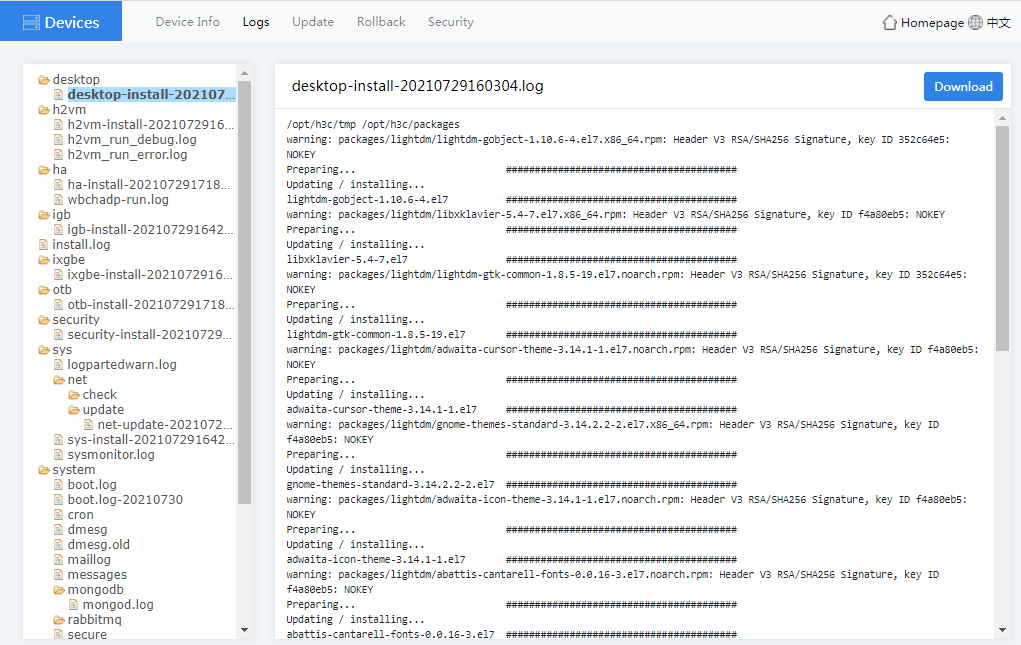
2. Click the Logs tab, you can view the detailed logs and perform the following tasks:
¡ To delete a log file, you can right-click a log folder name and select Delete.
¡ To download logs, you can right-click a log folder name and select Download, or click Download in the right corner of the page.
Figure4-38 Device logs page
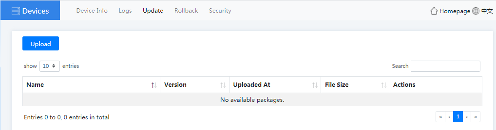
3. Click the Update tab to update the Device to the latest version, thus the device can use the latest features normally.
Figure4-39 Device update page
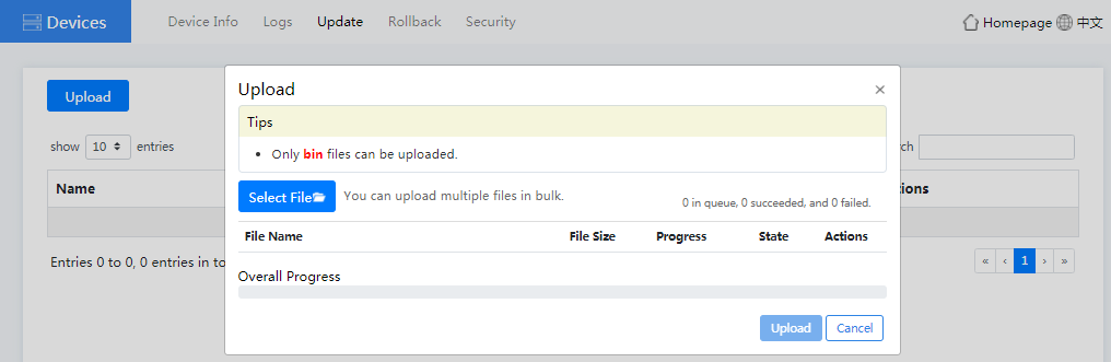
a. (Optional.) Click Upload. In the dialog box that opens, click Select File, select a file for upload, and then click Upload. After the file is uploaded to the Oasis platform, close the dialog box.
Figure4-40 Uploading a file
b. Click Update in the Actions column. In the dialog box that opens, click OK.
c. In the dialog box that opens, select an upgrade mode. The system version update will affect the service data.
- If you select Uninstall and Upgrade, the system first Uninstall the current system version and then update the system version. During the Uninstallation and update process, the device logout occurs and the device login page displays. After you log in to the device again, you can view the update progress. After the update is completed, a message indicating the successful update will pop up.
- If you select Update, the system will update the current system version to the specified system version.
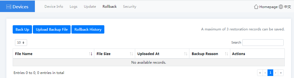
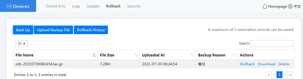
4. Click the Rollback tab to back up the configuration or rollback the history configuration.
Figure4-41 Device rollback page
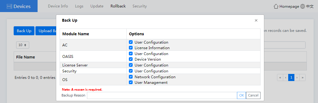
¡ To back up the device configuration, click Back Up. In the dialog box that opens, select the configuration of modules to be backed up and enter a backup reason, click OK.
Figure4-42 Backing up the device configuration
¡ After the configuration backup is completed, you can click Download, Rollback, or Delete as required.
Figure4-43 Managing the configuration file package
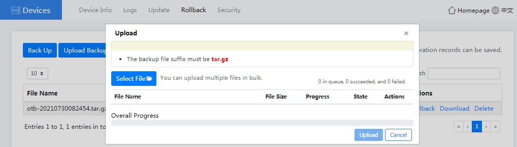
¡ To upload a backup file package, click Upload Backup File. In the dialog box that opens, click Select File, select a file package, and then click Upload.
Figure4-44 Uploading a backup file
¡ To roll back the history configuration, click Rollback History. You can then view and delete the rollback history records.
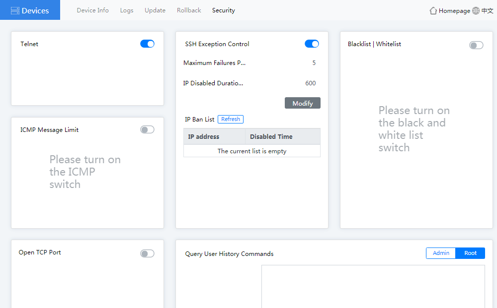
5. Click the Security tab. Then you can configure the following parameters:
¡ Telnet—If you disable Telnet, you cannot log in to the device through Telnet to ensure the system security.
¡ SSH Exception Control—With this feature enabled, the password brute force cracking and DOS attacks can be prevented. You can set the maximum failures per minute and IP disabled duration.
¡ ICMP Message Limit—With this feature enabled, you can prevent the frequent external device Ping packets from consuming the system resources.
¡ Blacklist/Whitelist—You can configure blacklists and whitelists to control the device access.
¡ Open TCP Port—With this feature enabled, the external devices can access the device only through the configured TCP port.
¡ Query User History Commands—You can use this feature to view the user history operations to determine whether the issue is caused by user improper operation.
Figure4-45 Device security page
5 Maintenance
The following information describes the guidelines and methods for daily device maintenance.
Guidelines
· Keep the equipment room where the device resides clean and tidy. Remove unnecessary devices or objects from the equipment room.
· Make sure the temperature and humidity of the equipment room meet the device operating requirements.
· Check the health status of the device through HDM regularly. If any health issue is detected, diagnose and resolve the issue immediately.
· Keep the operating system and software up to date as required.
· Make reliable backup plans:
¡ Schedule regular data backup tasks according to the server operating status.
¡ If data changes frequently, back up data any time when needed.
¡ Check the backed up data regularly to ensure that the data is stored correctly.
· Keep the network topology up to date to facilitate troubleshooting of networking problems.
Maintenance tools
The following tools are required for device maintenance:
· Temperature humidity meter—Monitors the operating environment of the device.
· HDM—Monitors the operating status of the device.
Maintenance operations
Monitoring the temperature and humidity in the equipment room
Use a temperature humidity meter to monitor the temperature and humidity in the equipment room.
The temperature and humidity in the equipment room must meet the device requirements. For information about the temperature and humidity requirements for device operation and storage, see "Temperature and humidity."
Examining cable connections
Verify that the cables and power cords are correctly connected.
Guidelines
· Do not use excessive force when connecting or disconnecting cables.
· Do not twist or stretch the cables.
· Organize the cables appropriately. For more information, see "Cabling guidelines."
Checklist
· The cable type is correct.
· The cables are correctly and firmly connected and the cable length is appropriate.
· The cables are in good condition and are not twisted or corroded at the connection point.
6 Appendix A Chassis views and technical specifications
Chassis views
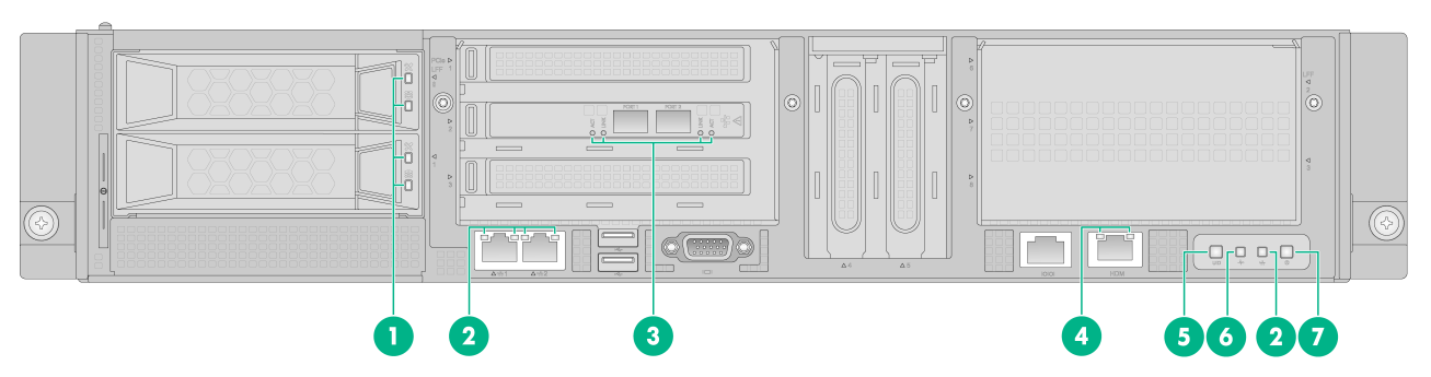
Figure6-1 Front panel
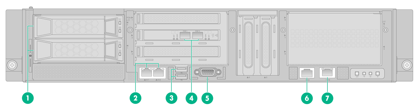
|
(1) 4TB drives |
(2) 1000BASE-T Ethernet ports |
|
(3) USB 2.0 connectors |
(4) SFP+ fiber ports |
|
(5) VGA connector |
(6) BIOS serial port |
|
(7) 1000BASE-T HDM dedicated network port (default IP address 192.168.1.2/24) |
|
Table6-1 Port and connector description
|
Port or connector |
Connector type |
Description |
|
4TB drive |
SATA |
N/A |
|
1000BASE-T Ethernet port |
RJ-45 |
Used together with an Ethernet cable to provide network connection. |
|
USB connector |
USB 2.0 |
Used for connecting the following USB devices: · USB flash disk. · USB keyboard or mouse. · USB optical drive. |
|
SFP+ fiber port |
LC |
Used together with an optical fiber to provide network connection. |
|
VGA connector |
DB-15 |
Used for connecting a display terminal, such as a monitor. |
|
BIOS serial port |
RJ-45 |
· Used for connecting to the device to locate the fault when remote access to the device fails. · Used for applications such as dongle and SMS modem. |
|
1000BASE-T HDM dedicated network port |
RJ-45 |
Used for logging in to the HDM Web interface. |
Figure6-2 Rear panel
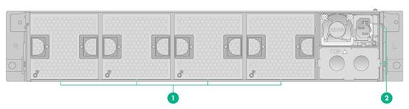
|
(1) Fan module slots |
(2) Power supply slots 1 and 2 |
Technical specifications
Table6-2 Technical specifications
|
Item |
Specifications |
|
Chassis height |
2 U 1 U equals 44.45 mm (1.75 in) |
|
Dimensions (H × W × D) (excluding the mounting brackets) |
87.5 × 440 × 451 mm (3.44 × 17.32 × 17.76 in) |
|
Weight (including two power supplies) |
14 kg (30.86 lb) |
|
Memory |
128 GB |
|
Storage |
4TB 6G SATA 7.2K 3.5in HDD General Intelligent Disk Equipment Module (FIO) |
|
Power supply |
550W power supply |
|
Power consumption |
≤ 194.1 W |
|
Rated input voltage |
100 to 240 VAC @ 50 or 60 Hz |
|
Network ports |
· 2 × embedded 1000 Mbps Ethernet ports · 2 × 10 Gbps Ethernet fiber ports · 1 × HDM dedicated network port |
|
I/O connectors |
· 2 × USB 2.0 connectors · 1 × VGA connector · 1 × BIOS serial port |
Table6-3 AC power supply specifications
|
Item |
Specifications |
|
Vendor model |
DPS-550AB-22 G |
|
Product code |
DPS-550AB-22 G |
|
Rated input voltage |
100 VAC to 240 VAC @ 50 or 60 Hz |
|
Rated power consumption |
550W |
7 Appendix B LEDs
Front panel LEDs
Figure7-1 Front panel LEDs
|
(1) Drive LEDs (upper: Fault/UID LED, lower: Present/Active LED) |
|
|
(2) 1000BASE-T port LEDs |
(3) SFP+ port LEDS |
|
(4) HDM dedicated network port LED |
(5) UID button/LED |
|
(6) Health LED |
(7) Power on/standby button and system power LED |
Table7-1 Drive LED description
|
Fault/UID LED status |
Present/Active LED status |
Description |
|
Flashing amber |
Steady green/Flashing green |
A drive failure is predicted. Replace the drive immediately. |
|
Steady amber |
Steady green/Flashing green |
The drive is faulty. Replace the drive immediately. |
|
Steady blue |
Steady green/Flashing green |
The drive is operating correctly and is selected by the RAID controller. |
|
Off |
Flashing green |
The drive is performing a RAID migration or rebuilding, or the system is reading or writing data to the drive. |
|
Off |
Steady green |
The drive is present but no data is being read or written to the drive. |
|
Off |
Off |
The drive is not securely installed or a drive failure has occurred. |
Table7-2 SFP+ port LED description
|
SFP+ port LED |
LINK |
ACT |
Description |
|
Steady on |
Flashing |
A link is present on the port, and the port is receiving or sending data. |
|
|
Steady on |
Off |
A link is present on the port, and the port is not receiving or sending data. |
|
|
Off |
Off |
No link is present on the port. |
Table7-3 Description for other LEDs and button
|
Button/LED |
Status |
|
1000Base-T Ethernet port LED |
· Steady green—A link is present on the port. · Flashing green—The port is receiving or sending data. · Off—No link is present on the port. |
|
HMD dedicated network port LED |
· Steady green—A link is present on the port. · Flashing green—The port is receiving or sending data. · Off—No link is present on the port. |
|
UID button LED |
· Steady blue—UID LED is activated. The UID LED can be activated by using the following methods: ¡ Press the UID button LED. ¡ Enable UID LED from HDM. · Flashing blue: ¡ Slow flashing—The firmware is being upgraded or the system is being managed from HDM. ¡ Fast flashing—HDM is restarting. To restart HDM, press the UID button LED for eight seconds. · Off—UID LED is not activated. |
|
Health LED |
· Steady green—The system is operating correctly, or a minor alarm has occurred. · Flashing green—Initializing HDM. · Slow flashing amber—A pre-alarm has occurred. · Fast flashing amber—A general alarm has occurred. · Flashing red—A severe alarm has occurred. |
|
Power on/standby button and system power LED |
· Steady green—The system has started. · Flashing green—The system is starting. · Steady amber—The system is in standby state. · Off—No power is present. The reasons might be the following: ¡ No power source is connected. ¡ No power supply is present. ¡ The installed power supplies are faulty. ¡ The system power LED is not connected correctly. |
Rear panel LEDs
Figure7-2 Rear panel LEDs
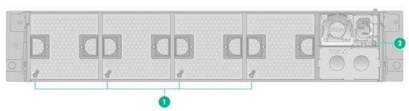
|
(1) Fan module status LEDs |
(2) Power supply status LED |
Table7-4 LEDs and buttons on the rear panel
|
LED |
Status |
|
Fan module status LED |
· Steady green—The fan module is operating correctly. · Steady red—The fan module is faulty. · Off—The fan module is not installed securely, or no power is present on the fan module. |
|
Power supply status LED |
· Steady green—The power supply is operating correctly. · Fast flashing green—Power is being input correctly but the system is not powered on. · Slow flashing green—The power supply is for backup and provides no power output. · Steady amber—Either of the following conditions exists: ¡ The power supply is faulty. ¡ The power supply does not have power input, but the other power supply has correct power input. · Flashing amber—An alert has occurred. · Off—Both power supplies do not have power input, which can be caused by incorrect power cord connection or power source shutdown. |
8 Appendix C Optional transceiver modules
Transceiver module, fiber connector, and optical fiber views
The device provides SFP+ ports. To connect an SFP+ port on the device, use an SFP+ transceiver module and an optical fiber with LC connectors.
Figure8-1 SFP transceiver module
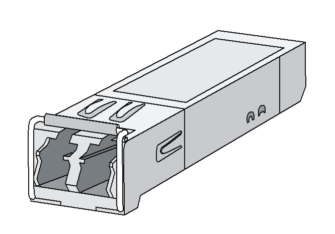
Figure8-2 SFP+ transceiver module
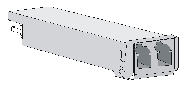
Figure8-3 Optical fiber with LC connectors
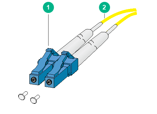
|
(1) LC connector |
(2) Optical fiber |
Transceiver module specifications
Table8-1 SFP-GE-LX-SM1310-A specifications
|
Item |
Specification |
|
Central wavelength |
1310 nm |
|
Max transmission distance |
10 km (6.21 miles)/550 m (1804.46 ft) |
|
Transmission rate |
1250 Mbps |
|
Connector type |
Duplex LC |
|
Fiber mode |
SMF/MMF |
|
Fiber diameter |
9 µm/50 μm (62.5 μm) |
|
Transmit power |
–9.5 to –3 dBm |
|
Receive sensitivity |
≤ –20 dBm |
|
Saturation |
≤ –3 dBm |
Table8-2 SFP-GE-SX-MM850-A specifications
|
Item |
Specification |
|
Central wavelength |
850 nm |
|
Max transmission distance |
550 m (1804.46 ft) |
|
Transmission rate |
1250 Mbps |
|
Connector type |
Duplex LC |
|
Fiber mode |
MMF |
|
Fiber diameter |
50 μm/62.5 μm |
|
Transmit power |
–9.5 to 0 dBm |
|
Receive sensitivity |
≤ –17 dBm |
|
Saturation |
≤ –3 dBm |
Table8-3 SFP-XG-LX-SM1310-E specifications
|
Item |
Specification |
|
Central wavelength |
1310 nm |
|
Max transmission distance |
10 km (6.21 miles) |
|
Transmission rate |
10.3125 Gbps |
|
Connector type |
Duplex LC |
|
Fiber mode |
SMF |
|
Fiber diameter |
9 µm |
|
Transmit power |
–8.2 to +0.5 dBm |
|
Receive sensitivity |
≤ –14.4 dBm |
|
Saturation |
≤ 0.5 dBm |
Table8-4 SFP-XG-SX-MM850-E specifications
|
Item |
Specification |
|
Central wavelength |
850 nm |
|
Max transmission distance |
300 m (984.25 ft) |
|
Transmission rate |
10.3125 Gbps |
|
Connector type |
Duplex LC |
|
Fiber mode |
MMF |
|
Fiber diameter |
50 μm/62.5 μm |
|
Transmit power |
–7.3 to –1 dBm |
|
Receive sensitivity |
≤ –9.9 dBm |
|
Saturation |
≤ 0.5 dBm |
