- Table of Contents
- Related Documents
-
| Title | Size | Download |
|---|---|---|
| 01-Text | 13.24 MB |
Sign in to HDM for rack servers
Sign in to HDM for blade servers
View summary information about the device
View information about other components
View storage summary information
View storage controller information
Power on or power off the server
Set the power supply operating mode
View power consumption information
Configure processor power states
View status and readings of temperature sensors
General restrictions and guidelines for network configuration
View dedicated network port information
Configure the dedicated network port
View shared network port information
Configure the shared network port
View port information in active/standby mode
Configure the active/standby mode
View services and user sessions
Launch a KVM or H5 KVM remote console
Operate the server from H5 KVM
Configure the VNC login password
Export HDM, BIOS, or RAID configuration
Import HDM, BIOS, or RAID configuration
Manage the intelligent security bezel
Installation package management
Firmware update restrictions and guidelines
Prerequisites for firmware update
Update the REPO for firmware update
Update HDM installation package
Update drive backplane firmware
Update firmware for retimer on the BIREN GPU module
Update firmware for storage controllers, network adapters, and drives
Configure the password policy for local users
Configure privileges for custom users
User roles and privileges matrix
Types of firewall rules and their priority order
Upload an SSL certificate and key to HDM
Configure two-factor authentication
Configure the security tip for login
Security monitoring information
Launch an H5 KVM remote console
Intelligent load configuration
Mount images through a Windows CIFS server
Mount images through a Linux CIFS server
Set up a Linux syslog server based on UDP or TCP
Set up a Linux syslog server based on TLS
About HDM
Introduction
Hardware Device Management (HDM) is a remote server management system that can satisfy the requirements of both individual and data center computing and storage. It applies to scenarios of HPC, AI, databases, cache servers, file servers, and storage servers.
HDM2 is an upgrade version of HDM. It inherits existing features, makes optimizations for multiple scenarios such as server intelligent diagnosis, host monitoring, energy efficiency management, and security management, and provides features for corresponding software and hardware versions. In this document, HDM2 is referred to simply as HDM.
HDM provides the following abundant features:
· Various management interfaces
¡ HDM provides IPMI, HTTPS, SNMP, and Redfish, to meet various system integration requirements.
¡ HDM is compatible with IPMI v1.5 and IPMI v2.0 and provides a standard management interface for standard management system integration.
· Remote maintenance
¡ HDM provides remote access to the server through KVM (keyboard, video, and mouse), VNC, and virtual media, enabling convenient server monitoring and management.
¡ HDM supports out-of-band RAID monitoring and configuration to improve RAID configuration efficiency and management capability.
¡ HDM supports importing and exporting HDM, BIOS, or RAID configuration to improve remote server management efficiency.
· Fault monitoring and diagnosis
¡ HDM supports taking a screenshot or records a video upon a system crash for future troubleshooting.
¡ HDM supports using syslog messages, traps and emails to report alarms for troubleshooting.
¡ HDM provides all-round server monitoring, alarming, and event logging. It monitors server operation, for example, CPU failure, voltage, and fan failure, and generates alarms and logs if any event occurs, such as memory failure, drive failure, or power supply failure.
¡ HDM supports Smart Hardware Diagnosis (SHD) for component fault diagnosis, bringing ease to fault location and faulty component replacement.
· Firmware update
¡ HDM supports firmware out-out-band update for multiple types of firmware, such as HDM, BIOS, CPLD, and PSU.
¡ HDM supports hot and cold patch upgrades, which does not interrupt the system operation during fault repairs.
· Networking
¡ HDM supports VLANs and the sideband technology that allows for flexible network management.
¡ NTP is available for time synchronization to improve time precision on the server.
¡ HDM supports domain services and directory services to simplify user management and improve security of user management.
· Security management
¡ HDM supports primary/backup image switchover. The switchover enables startup by using the backup image if the system crashes, which enhances system availability.
¡ HDM provides various user interfaces to ensure user login security.
¡ HDM supports uploading and replacing certificates to enhance data transmission security.
¡ HDM supports two-factor authentication to enhance the security performance of system management.
¡ HDM supports SSH keys to safeguard user security during login.
¡ Platform Firmware Resiliency (PFR) is used to protect HDM from attacks.
¡ HDM supports security erase to protect user data from leakage.
· Smart power supply management
¡ HDM provides power capping to precisely control the power consumption of each server, helping arranging energy supply.
¡ HDM supports clod backup power supply check to verify whether the power supply group is operating correctly, improving power stability.
¡ HDM supports configuring processor power states and the power supply operating mode to achieve power saving.
· Unified control
HDM supports managing servers in bulk to improve efficiency.
Various management interfaces
HDM supports management through Web, Redfish, IPMI, and SNMP interfaces.
HDM Web interface
HDM Web interface provides a convenient configuration query interface. Multiple modules are integrated on the HDM Web interface based on feature implementation, including Dashboard, System, Configuration, Remote Services, O&M Diagnosis, Firmware & Software, Users & Security, and Unified Control. Some servers also support Intelligent Power Efficiency.
HDM supports both Chinese and English. You
click the ![]() button to change the language to Chinese
and English, respectively.
button to change the language to Chinese
and English, respectively.
To access the online help, you can click the ![]() button.
button.
Redfish management interface
HDM supports the standard Redfish management interface. The Redfish client as a Redfish interface tool such as Postman, sends HTTPS requests to the server, and performs information query, configuration, and monitoring through the GET, PATCH, POST, or DELETE command.
For more information about Redfish, see H3C HDM2 Redfish API Reference.
IPMI management interface
HDM supports IPMI 1.5 and IPMI 2.0. IPMI is a server management system standard that provides server management on different types of hardware. It enables multiple platform-integrated management.
Baseboard Management Controller (HDM) is the core controller in IPMI that enables system management software to exchange information for server management.
IPMI provides the following out-of-band management and monitoring features:
· Asset management.
· Fault monitoring.
· Logging.
· Recovery control.
For information about supported IPMI commands, see H3C HDM2 IPMI Basics Command Reference.
SNMP management interface
Simple Network Management Protocol (SNMP) defines the standard management framework, common communication languages, and security and access control mechanisms for device monitoring and management in a network. It is widely used for remote management and operation on network devices.
HDM provides SNMP-based programming interfaces. SNMP supports GET and SET operations, and trap sending. Third-party management software can manage servers in a centralized manner by using SNMP interfaces. The SNMP agents support SNMPv1, SNMPv2c, and SNMPv3.
An SNMP agent supports displaying the following information: system health status, hardware status, memory and processor models, alarm reporting configuration, power statistics, asset information, heat dissipation management, firmware version, and network management.
Applicable products
This document is applicable to the following products:
· H3C UniServer R4700 G6
· H3C UniServer R4700LE G6
· H3C UniServer R4900 G6
· H3C UniServer R4900 G6 Ultra
· H3C UniServer R4900LE G6
· H3C UniServer R4950 G6
· H3C UniServer R5300 G6
· H3C UniServer R5350 G6
· H3C UniServer R5500 G6
· H3C UniServer B5700 G6
· H3C UniServer R6700 G6
· H3C UniServer R6900 G6
Using this document
The figures of hardware options used in this document are for illustration only and might differ from your product.
The screenshots in this document are subject to change over time.
Some data in this document is used as an example and might differ from your product.
This document is available for HDM2-1.XX software versions.
Before you start
Guidelines for using HDM
· As a best practice, use a dedicated network port to manage and configure HDM.
· Do not connect HDM to the Internet directly.
· Do not use insecure protocols or ports.
· Audit the operation logs periodically.
Default parameter settings
Table 1 describes the default parameter settings. As a best practice, change the default parameter values at your first access to HDM and update the default parameter values periodically.
Table 1 Default parameter settings
|
Parameter |
Default value |
|
Username |
admin |
|
Password |
Password@_ |
|
IPv4 address of the dedicated network port |
192.168.1.2/24 |
|
SNMP read-only community name |
rocommstr |
|
SNMP read-write community name |
N/A |
|
Trap community name |
public |
HDM users
HDM supports the following types of users:
· Local users—HDM supports a maximum of 16 local users. The local access mode is suitable for small-size scenarios such as laboratories and small- and medium-sized enterprises.
· Domain users (LDAP users, AD users and Kerberos users)—The number of users and user permissions are configured and managed on the domain server. This access mode is suitable for environments that require unified authentication.
Sign in to HDM
The following information describes the prerequisites for a successful sign-in to HDM, the default sign-in parameters, the sign-in procedure, and global operations for all pages.
Sign in to HDM for rack servers
Prepare for an HDM sign-in
Before you sign in to the HDM Web interface, make sure all preparation requirements are met.
Set up the HDM client
HDM does not require installation of client software. You can use a Web browser to access HDM.
Make sure the browser and resolution setting of the configuration terminal meet the requirements in Table 2.
Table 2 Browser and resolution requirements
|
Browsers |
Resolution |
|
Google Chrome 80 (or higher) Mozilla Firefox 90.0.0 (or higher) Safari 14 (or higher) Microsoft Edge 108 (or higher) |
To ensure that you can view a full webpage, use the following resolutions as a best practice: · 1280*800 · 1366*768 · 1440*900 · 1600*900 · 1600*1200 · 1680*1050 · 1920*1080 · 1920*1200 |
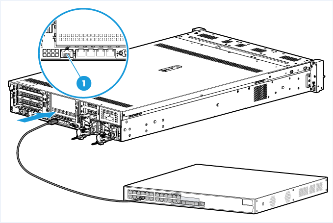
Connect the server to the network
Connect either of the following network ports on the server to the network:
· HDM shared network port—Transmits HDM management traffic and server data traffic simultaneously. This port is available on all servers.
· HDM dedicated network port—Transmits only HDM management traffic. This port is not available on blade servers.
For network port configuration on rack or storage servers, see "Network." For network port configuration on blade servers, see "Configure the shared network port."
Figure 1 Connecting the server to the network
Obtain the HDM sign-in settings
To sign in to HDM, you must obtain its management IP address and user account information.
On the first sign-in, use the default settings in Table 3. To change the management IP address after login, see "Network."
Table 3 Default HDM sign-in settings
|
Item |
Default setting |
|
IP address |
HDM shared network port: DHCP HDM dedicated network port: 192.168.1.2/24 |
|
Username |
admin |
|
Password (case-sensitive) |
You can obtain the HDM management IP address from the POST screen of the BIOS. As shown in Figure 2, the POST screen displays the IPv4 addresses of the shared and dedicated network ports at the upper right corner, and the IPv6 addresses at the lower left corner.
Figure 2 Obtaining the HDM management IP address (BIOS version 6.00.05)

Sign in to HDM
Restrictions and guidelines
By default, the session timeout is 30 minutes. If no operation is performed within 30 minutes, the system logs you out.
After five consecutive password check failures, your account will be locked for five minutes.
For security purposes, change the default username and password at the first login, and update your password periodically.
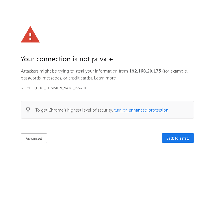
The default self-signed SSL certificate for HDM login will prompt a warning dialog box.
Procedure
1. Open the browser, and enter the HDM management IP address. This section uses Google Chrome as an example.
2. On the security certificate page that opens, click Continue to 192.168.88.89 (not secure).
Figure 3 Security certificate confirmation page
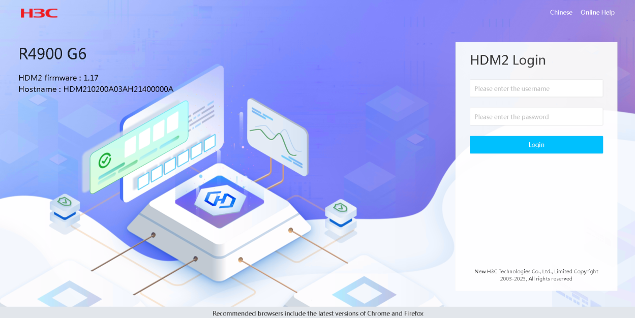
3. On the sign-in page, enter the username and password, and then click Sign in.
If this is the first sign-in, enter the default username (admin) and password (Password@_). The password is case sensitive.
Figure 4 HDM sign-in page
4. Click Chinese or English to change the language if needed.
5. If this is the first sign-in, change the username and password for security purposes as described in "User management."
6. If Kerberos authentication is enabled correctly, you can click Login to log in to the HDM Web interface directly without a username and password.
Figure 5 Login

Sign in to HDM for blade servers
For blade servers, HDM is accessible only from OM. You can access HDM from the Remote Consoles page without being authenticated or by clicking the HDM network IP address from the blade server information page.
Only OM administrator users and operator users that have the HDM access privilege can access HDM from OM.
The HDM sign-in procedure is the same for blade servers. This section uses the procedure for blade servers as an example.
HDM sign-in flowchart

Prepare for an HDM sign-in
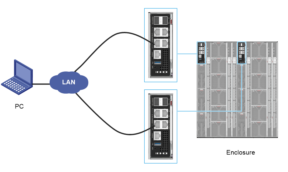
Setting up the configuration environment
As shown in Figure 6, use a local PC as the HDM client and connect the PC to the management (MGMT) ports on the active and standby OM modules. For more information about port locations, see the labels on the front panel of the OM modules.
Figure 6 Setting up the configuration environment
Obtain OM sign-in settings
To sign in to the OM Web interface, you must obtain its management IP address and user account information. On the first sign-in, use the default settings in Table 4.
Table 4 Default OM sign-in settings
|
Item |
Default setting |
|
IP address |
192.168.100.100/24 |
|
Username |
admin |
|
Password (case-sensitive) |
Password@_ |
Set up the HDM client
HDM does not require installation of client software. You can use a Web browser to access HDM. To ensure login success, follow these restrictions:
· Make sure the IP address of the HDM client is in the same network segment with the management IP addresses of OM modules and HDM. You can obtain the HDM management IP address from the OM Web interface. For more information, see OM online help.
· Make sure the browser and resolution setting of the configuration terminal meet the requirements in Table 5.
Table 5 Browser and resolution requirements
|
Browsers |
Resolution |
|
Google Chrome 58.0 (or higher) |
Recommended: 1600*900 (or higher) |
Sign in to OM
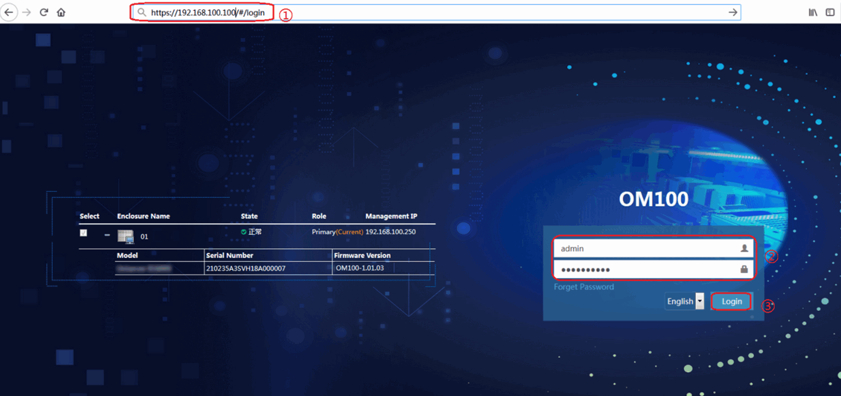
1. Open the browser, and enter the OM management IP address in the format of https://OM_ip_address.
2. On the sign-in page, enter the username and password, and then click Login.
If this is the first sign-in, enter the default username (admin) and password (Password@_). The password is case sensitive.
Figure 7 Signing in to OM
Sign in to HDM
Authentication-free access
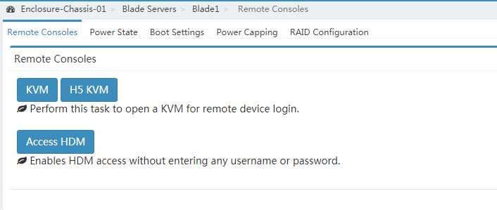
1. In the navigation pane of the OM Web interface, click Blade Servers, select the target server, and then click Remote Consoles.
2. On the Remote Consoles tab, click the Access HDM button to sign in to HDM, as shown in Figure 8.
If this is the first sign-in, click the Proceed to link as shown in Figure 8 to trust the webpage that opens.
Figure 8 Authentication-free access
The HDM Web interface opens.

HDM network IP access
1. In the navigation pane of the OM Web interface, click Blade Servers, and then select the target server.
2. In the HDM Network Info section, click the IP address link from the IPv4 Address field, as shown in Figure 10.
If this is the first sign-in, click the Proceed to link as shown in Figure 10 to trust the webpage that opens.
Figure 10 HDM network IP access

The HDM Web interface opens.
Figure 11 HDM Web interface
Global operations
You can perform the following operations on any HDM page:
· To change the language, click ![]() .
.
· To access the HDM online
help, click ![]() .
.
· To log out, click ![]() .
.
· To refresh the page, click ![]() .
.
View device information
View summary information about the device
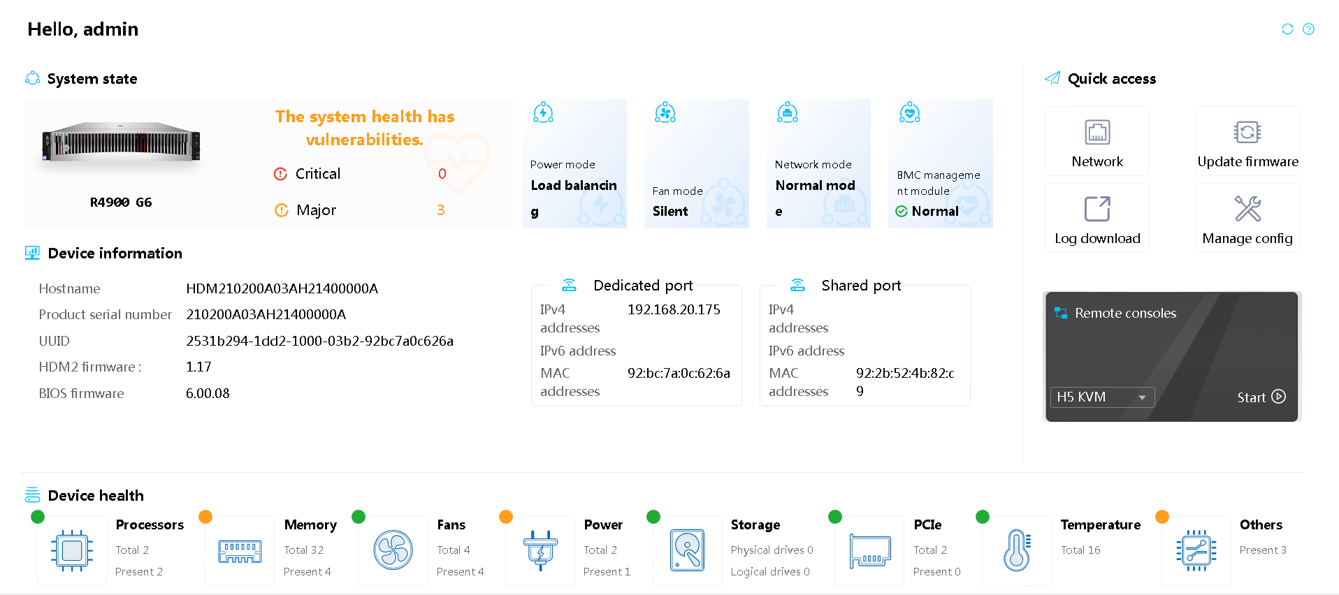
The Dashboard presents summary information about the device, including basic information about the device, system health status, system alarm information, power mode, fan mode, network mode, HDM management module ststus, and shortcuts for you to quickly access the desirable function or feature menus.
Procedure
Select Dashboard on the top navigation bar. Summary information about the device is displayed.
Parameters
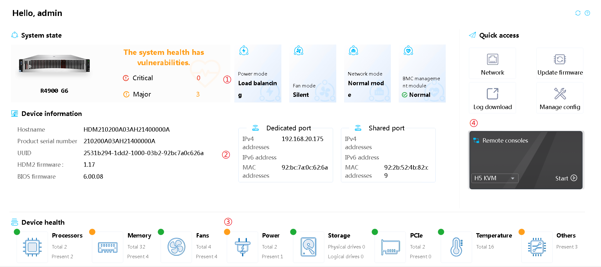
The work pane provides the following sections:
· Section 1—Displays the server status and basic information about the server.
¡ System state: Displays health status of the server.
- ![]() Normal—All server components are operating correctly.
Normal—All server components are operating correctly.
- ![]() Critical,
Critical, ![]() Major—A minimum
of one component is experiencing issues.
Major—A minimum
of one component is experiencing issues.
¡ Alarm information
- Major—The event might cause part of the system to fail and result in service interruption. Immediate action is required.
- Critical—The event might result in system outage or power failure. Immediate action is required.
¡ Power mode: Role of the power supply. Options include Active and Standby. The active power supplies provide power normally and the standby power supplies provide low power output.
¡ Fan mode
- Silent: Enables the fans to run at the lowest speed required by heat dissipation of the server. This mode is suitable for scenarios with high noise requirements.
- Balanced: Enables the fans to run at a higher speed to provide balanced noise control and cooling performance.
- Powerful: Enables the fans to run at the highest possible speed. This mode is suitable for scenarios where the server requires high cooling performance. For example, the server is busy and key components, such as processors, are heavily loaded, or the ambient temperature changes frequently.
- Custom: Specifies a customized fan speed level. A higher level represents a higher speed and larger noise.
¡ Network mode
- Normal mode—The HDM dedicated and shared network ports have separate IP addresses and operate in active/active mode. HDM is accessible at both ports.
- Active/standby mode—The HDM dedicated and shared network ports have separate IP addresses and operate in active/standby mode. In this mode, the dedicated port is the primary port and the shared network is the secondary port. HDM is accessible at the dedicated port as long as the dedicated port is up and has network connectivity. After the dedicated port fails, HDM is accessible at the shared port. In standby mode, the shared port cannot forward management traffic, but it can still forward data traffic.
¡ HDM management module
- PCB: Printed Circuit Board (PCB) version number for HDM.
- CPLD: Complex Programmable Logical Device (CPLD) version for HDM.
- Video memory: Video memory capacity for HDM.
- Backup plan: The system uses the Golden Image embedded in the server system as the backup image for HDM firmware.
- ECC CE errors: Number of ECC correctable errors detected by HDM.
- ECC UCE errors: Number of ECC uncorrectable errors detected by HDM.
- SD card state: State of the SD card on the HDM management module. Options include Normal, Partition lost, Access failed, and Absent.
¡ iFIST module
- SD card state: State of the SD card on the iFIST module. Options include Absent and Normal.
- SD card size: Capacity of the SD card on the iFIST module.
- Version: iFIST software version number.
· Section 2—Displays the device information.
¡ Product serial number: A unique product code assigned by the manufacturer.
¡ UUID: Universally unique identifier of the server.
¡ HDM firmware: Current firmware version of HDM. For more information about updating the firmware, see "Firmware update."
¡ BIOS firmware: Current firmware version of the BIOS. For more information about updating the firmware, see "."
¡ Dedicated port: Processes management
traffic only. The ![]() icon represents a correct network connection, and the
icon represents a correct network connection, and the ![]() icon
represents an incorrect network connection for the port.
icon
represents an incorrect network connection for the port.
¡ Shared port: Processes both
management traffic and data traffic. The ![]() icon represents a
correct network connection, and the
icon represents a
correct network connection, and the ![]() icon represents
an incorrect network connection for the port.
icon represents
an incorrect network connection for the port.
¡ Active/standby mode: Port used by the active/standby network mode. This field is displayed only when the active/standby network mode is enabled.
¡ Hostname: By default, the server name is not configured. Support for this field depends on the server model.
¡ IPv4 address: IPv4 address of HDM management port.
¡ IPv6 address: IPv6 address of HDM management port.
¡ MAC address: MAC address of the HDM management port.
¡ Chip model:Chip model of HDM.
· Section 3—Displays the health status of the device components.
¡ ![]() Normal: The component is operating correctly.
Normal: The component is operating correctly.
¡ ![]() Major: The component performance is degraded
significantly.
Major: The component performance is degraded
significantly.
¡ ![]() Critical: The server might shut down to prevent component
damage.
Critical: The server might shut down to prevent component
damage.
Table 6 Component health status
|
Component |
Health status |
Description |
|
Processors |
|
The processors are operating correctly. |
|
|
One of the following conditions exists: · An overtemperature condition has occurred. · The processor configuration is incorrect. |
|
|
|
One of the following conditions exists: · The temperature of a processor has exceeded the critical threshold. · An unrecoverable processor error has occurred. · The primary processor is absent. · BIOS halt has occurred during POST because of a processor error. |
|
|
Memory |
|
The memory is operating correctly. |
|
|
One of the following conditions exists: · All memory modules are absent or isolated. · An unrecoverable memory error has occurred. · A DIMM is not correctly installed or a DIMM compatibility error occurred. |
|
|
|
BIOS halt has occurred during POST because of a memory error. |
|
|
Fans |
|
The fans are operating correctly in redundancy. None of the fans at critical locations has failed or all present fans are operating correctly. |
|
|
Fan redundancy issue is present. Fans at critical locations in the same fan tray have failed. |
|
|
|
Fan redundancy issue is present because fans at two or more critical locations in different fan trays have failed. |
|
|
Power supplies |
|
The power supplies are operating correctly. |
|
|
A severe power supply error has occurred. |
|
|
Storage |
|
All logical drives, physical drives, and storage controllers are operating correctly. |
|
|
One of the following conditions exists: · A logical drive error has occurred. · A major physical drive error has occurred. · A storage controller error has occurred. |
|
|
PCIe modules |
|
The PCIe modules (network adapters, GPUs, FC HBAs, QAT cards, and FPGA cards) are operating correctly. |
|
|
A bus uncorrectable error, bus fatal error, or PCIe module (network adapter, GPU, FC HBA, QAT card, or FPGA card) error has occurred. |
|
|
Temperature |
|
All component temperatures are below the major threshold. |
|
|
A component temperature has crossed the major threshold, but it has not reached the critical threshold. Immediate action is required. |
|
|
|
A component temperature has crossed the critical threshold. Immediate action is required. |
|
|
Others |
|
All components are operating correctly. |
|
|
A major error has occurred on a minimum of one component. |
|
|
|
A critical error has occurred on a minimum of one component. |
· Section 4—Provides shortcuts for you to quickly access the desirable function or feature menus.
To access a remote console, you must first click Start KVM or Start H5 KVM on the redirected page. For information about the KVM and H5 KVM launch modes, see "Launch a KVM or H5 KVM remote console."
Virtual buttons
The HDM Web interface provides buttons on the top right corner. Table 7 provides information about the buttons.
|
Button name |
Icon |
Description |
|
My tasks |
|
You can click this icon to view the ongoing tasks, including firmware update, log downloading, and virtual media mounting. If multiple tasks are in progress, the system displays only the four most recent tasks. To view more information, click View details to view the task ID, name, description, state, and creation time. |
|
UID LED |
|
The server is selected. |
|
|
· Firmware update is being performed or the remote console is open. · SDS log download through a service USB drive is in progress. |
|
|
|
The UID LED on the server is off. |
|
|
Server power |
|
The server is powered on. When you click this button, the following power options are displayed for you to change the power status of the server. · Force system reset—Warm reboots the server without power cycling the server. · Force power-off—Shuts down the server immediately by force. This action is equivalent to pressing the power button on the server for five seconds. · Graceful power-off—Shuts down the operating system first, and then removes power from the server. · Force power-cycle—Powers off and then powers on the server. |
|
|
The server is powered off. · Power on—Starts up the server. |
|
|
Language |
|
If the interface is in English, you can click the button to change the language to Chinese. |
|
If the interface is in English, you can click the button to change the language to English. |
||
|
Theme |
|
If the interface is in light theme, you can click the button to change the interface theme to starry theme. If the interface is in starry theme, you can click the button to change the interface theme to light theme. |
|
Alarm |
|
Displays detailed information about an alarm. |
|
Security monitoring information |
|
Security monitoring is disabled. You can click the icon to access the Security Monitoring Information page. |
|
|
No risk exists for security settings. You can click the icon to access the Security Monitoring Information page. |
|
|
|
Risks are ignored for all security settings. You can click the icon to access the Security Monitoring Information page. |
|
|
|
Risks exist for security settings. You can click the icon to access the Security Monitoring Information page. |
|
|
User |
|
You can click the button to view the session IDs, session types, user IDs, usernames, IP addresses, user roles, and user types of all online users, delete sessions, or exit the system. |
|
Refresh |
|
Refreshes the webpage. |
|
Online help |
|
Accesses the online help. |
System
View summary information
The Summary menu allows you to view information about the server, processors, memory, PCIe modules, sensors, and other components.
The supported configurations vary by server model.
|
|
NOTE: · HDM can display correct, complete processor, memory, and PCIe module information only after the server completes POST. · If the server is off, HDM displays the processor, memory, and PCIe module information obtained at the most recent POST. |
View device information
Procedure
1. On the top navigation bar, click System.
You are placed on the Summary page.
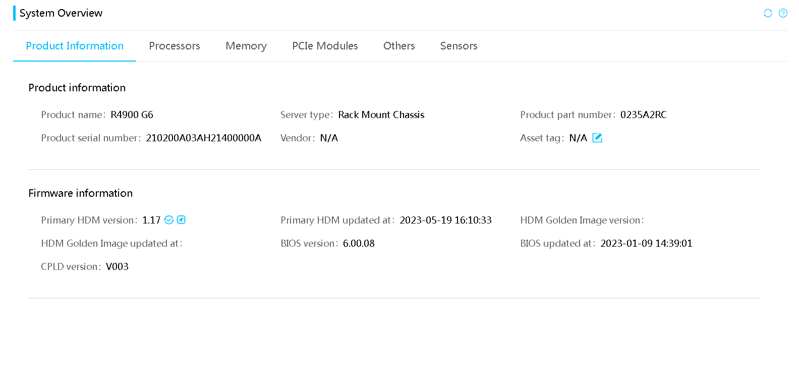
2. Click the Product Information tab to view device and firmware information.
Figure 13 Viewing device information
Parameters
Product information
· Device name: Server model.
· Server type: Server type.
· Part number: Part number of the server, which corresponds to the server model. This field displays N/A if the system fails to obtain the server part number.
· Product serial number: Serial number of the server.
· Manufacturer: Manufacturer of the server.
· Asset tag: Asset tag of the server. This field is optional. The asset tag is a string of 1 to 48 characters and can contain only letters, digits, spaces, and the following special characters: ` ~ ! @ # $ % ^ & * ( ) _ + - = [ ] { } | ; ' : \ " , . / < > ?
Firmware information
· Primary HDM version: Firmware version of the primary HDM image. Hover over the ![]() icon, the system prompts that the current
HDM version is primary version. You can click the
icon, the system prompts that the current
HDM version is primary version. You can click the ![]() icon
to access the "Installation package management" page for detailed information.
icon
to access the "Installation package management" page for detailed information.
· Primary HDM complied at: Most recent update time of the primary HDM image.
· HDM
Golden Image version:
Firmware version of the backup image. Hover over the ![]() icon,
the system prompts that the current HDM version is backup version.
icon,
the system prompts that the current HDM version is backup version.
· HDM Golden Image updated at: Time at which the backup image version was compiled.
· BIOS version: Version of the Basic Input Output System (BIOS).
· BIOS compiled at: Time at which the BIOS was compiled.
· ME version: Version of the Intel Management Engine (ME). This field is available only for servers installed with an Intel processor.
· CPLD1 version: Version of the primary CPLD firmware.
View processor information
Perform this task to view summary and detailed processor information and processor errors.
Procedure
1. On the top navigation bar, click System.
You are placed on the Summary page.
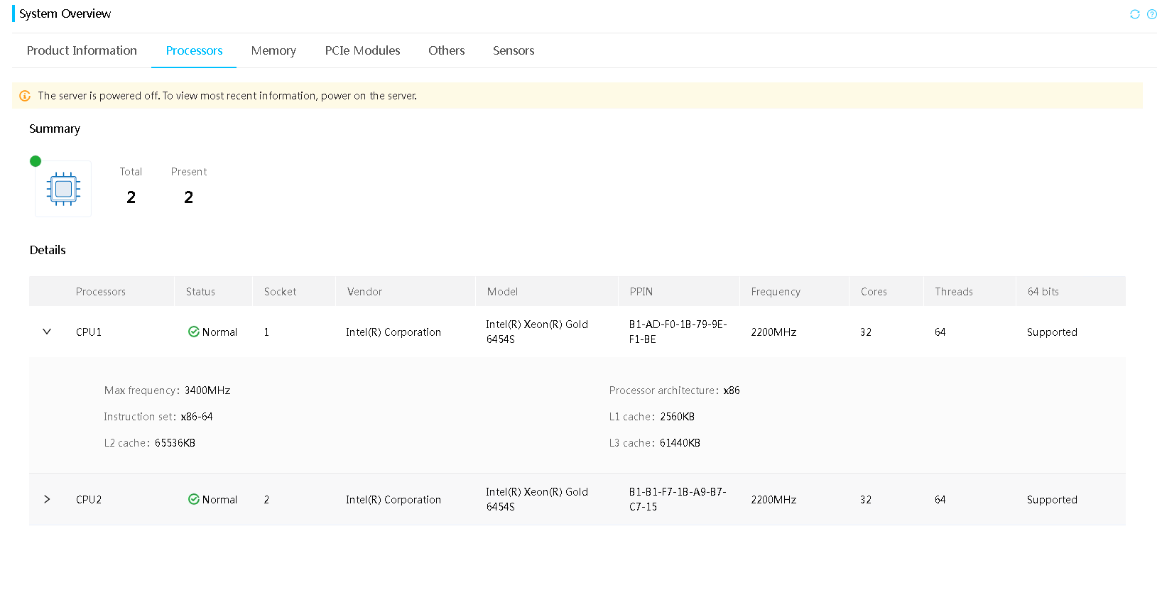
2. Click the Processors tab to view processor information.
Figure 14 Viewing processor information
Parameters
· Status: Operating status of the processor. If a processor is in abnormal state, view the fault description to locate the errors.
· Socket: Slot number of the processor.
· Model: Model of the processor.
¡ An Extreme Core Count (XCC) processor can be configured with a relatively large amount of cores, which belongs to an advanced configuration.
¡ A Medium Core Count (MCC) processor can be configured with a medium amount of cores, which belongs to a medium configuration.
· PPIN: Unique product code assigned by the manufacturer. This field displays N/A if HDM fails to obtain the PPIN.
· Max frequency: Maximum frequency of the processor.
· Frequency: Base frequency of the processor.
· Cores: Cores of the processor.
· Threads: Number of the threads supported by the processor.
· 64 bits: Indicates whether the processor supports 64-bit computing.
· Processor architecture: Framework of the processor. Only the x86 architecture is supported.
· Instruction set: Type of the processor instruction set for processing and computing, only X86-64 supported.
· L1 cache: L1 cache of the processor.
· L2 cache: L2 cache of the processor.
· L3 cache: L3 cache of the processor.
· Serial number: Unique serial number assigned by the manufacturer. This field displays N/A if HDM fails to obtain the serial number. Support for this field depends on the device model.
· Fault description: Alarms generated for processor errors.
· Other parameters: ChopType and Stepping fields of the processor.
View memory information
Perform this task to view summary, RAS, view, and detailed memory information, and memory errors.
Restrictions and guidelines
If a DIMM is disabled because of a memory training error, the other DIMM in the same channel will also be disabled.
Procedure
1. On the top navigation bar, click System.
You are placed on the Summary page.
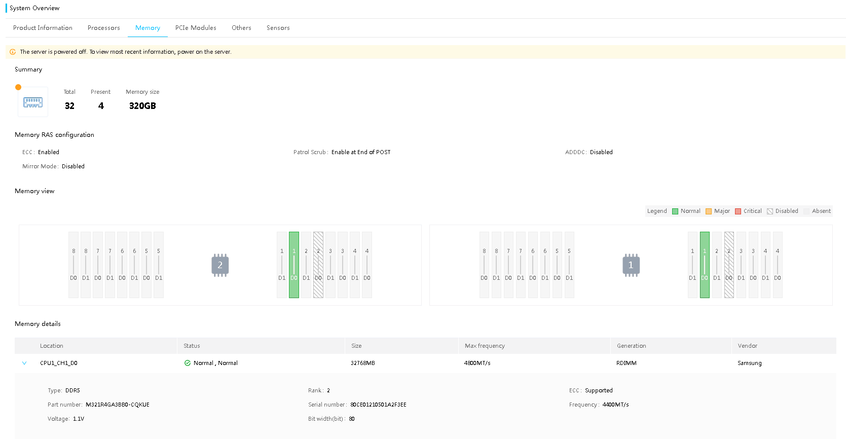
2. Click the Memory tab to view memory information.
3. (Optional.) Select the target compute module to view the corresponding memory information.
Figure 15 Viewing memory information
Parameters
The field for memory reliability, availability, and serviceability (RAS) configuration is displayed only when RAS mode is enabled.
· ECC: Support for error-correcting code (ECC). Available options include:
¡ 48-bit ECC.
¡ 96-bit ECC.
¡ 125-bit ECC.
¡ 128-bit ECC.
· Patrol Scrub: Patrol scrubbing settings. Patrol scrubbing allows a processor to automatically search for and correct correctable memory errors at regular intervals.
· SDDC: Enablement status of DRAM Single Device Data Correction (SDDC), which can correct multiple bit errors in x4 or x8 chips.
· ADDDC: Enablement status of Adaptive Double Device Data Correction Sparing (ADDDC), which can correct two-bit memory errors.
· Mirror Mode: Mirror mode. Available options include:
¡ Disabled—Disables memory mirroring.
¡ Full Mirror Mode—Sets the entire 1LM memory in the system to be mirrored.
¡ Partial Mirror Mode—Sets a part of the 1LM memory in the system to be mirrored.
Memory details (available for all DIMMs)
· Location: Processor ID, channel ID, and slot number of a DIMM.
· Status: Health status and authenticity status of a memory module. If a DIMM is in abnormal state, view the fault description to locate the errors. The authenticity status indicates whether the memory is vendor certified and available options include:
¡ Vendor certified—The module has been certified.
¡ Normal—The module has not been certified.
· Size: Capacity of the DIMM.
· Max frequency: Main frequency of the memory module.
· Generation: Generation of the DIMM.
· Vendor: DIMM manufacturer.
· Type: DIMM type.
· Rank: Rank type of the DIMM. Options include SR DIMM, DR DIMM, and QR DIMM.
· ECC: Support for error-correcting code (ECC).
· Serial number: Unique product code assigned by the manufacturer. This field displays N/A if HDM fails to obtain the serial number.
· Part number: Part number of the DIMM. This field displays N/A if HDM fails to obtain the part number.
· Frequency: Frequency at which the memory operates.
· Voltage: Voltage for the memory.
· Bit width: Memory bit width.
View PCIe module information
Restrictions and guidelines
If a PCIe module is present and the present PCIe module does not support information obtaining, you can view the available empty physical slots and maximum bandwidth information. If a physical slot is a riser card slot, you can also view the corresponding riser card information.
If the system cannot obtain the current power, verify that the GPU driver has been installed.
To enable the Management Component Transport Protocol (MCTP) feature, first update the system firmware to a version that supports MCTP. Then, access the BIOS setup utility, access the Advanced > Platform Configuration > Server ME Configuration menu, enable MCTP proxy, and then restart the server.
Procedure
1. On the top navigation bar, click System.
You are placed on the Summary page.
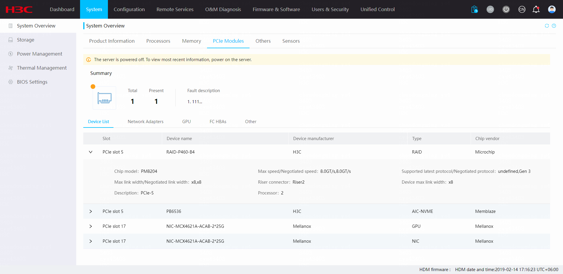
2. Click the PCIe Modules tab to view PCIe module information.
3. To view information about a type of PCIe modules, click the corresponding tab.
Figure 16 Viewing PCIe module information
Parameters
Device list
· Device information
¡ Slot: Slot of the PCIe module. For more information about slot locations, see the user guide for the server.
¡ Status: PCIe module status, including Normal and Abnormal.
¡ Device name: Model of the PCIe module.
¡ Device manufacturer: Manufacturer of the PCIe module.
¡ Type: Type of the PCIe module.
¡ Chip vendor: Chip manufacturer of the PCIe module.
¡ Serial number: Unique product code assigned by the manufacturer. This field displays N/A if HDM fails to obtain the serial number.
¡ Part number: Part number of the PCIe module, which corresponds to the model of the PCIe module. This field displays N/A if HDM fails to obtain the part number.
¡ Chip model: Chip model of the PCIe module.
¡ Max speed: Maximum PCIe link rate.
¡ Negotiated speed: Auto-negotiated PCIe link rate.
¡ Max protocol: Supported latest generation of the PCIe standard.
¡ Negotiated protocol: Auto-negotiated generation of the PCIe standard.
¡ Max link width: Maximum link width supported by the PCIe slot.
¡ Max link width: Maximum link width supported by the PCIe module.
¡ Negotiated link width: Auto-negotiated link width of the PCIe module.
¡ Description: Description of model and position the PCIe device. Models include PCIe and OCP.
¡ Mezzanine slot: Slot number of the mezzanine PCIe module. This field is displayed only for blade servers.
· Slot information
¡ Processor: Processor to which the PCIe module is subordinate. Support for this field depends on the device model.
¡ Riser connector: Connector number of the riser card where the PCIe module is installed.
¡ Max link width: Maximum link width supported by the PCIe slot.
Network adapters
· Device name: Name of the network adapter.
· Port: Port type of the network adapter.
· Device manufacturer: Manufacturer of the network adapter.
· Chip vendor: Chip manufacturer of the network adapter.
· Mezzanine slot: Slot number of the mezzanine PCIe module. This field is displayed only for blade servers.
· Firmware: Firmware version of the network adapter.
· Status: Network adapter health status. If a network adapter is in abnormal state, review the event logs to locate the errors.
· Location: Physical location of the network adapter.
· OCP fan status: Status of OCP network adapter fans. Options include Absent, Normal, and Major.
· Part number: Part number of the PCIe module, which corresponds to the model of the PCIe module. This field displays N/A if HDM fails to obtain the part number.
· Serial number: Unique product code assigned by the manufacturer. This field displays N/A if HDM fails to obtain the serial number.
· Chip model: Chip model of the network adapter.
¡ Mode: Mode of the network adapter.
- Single: Normal mode.
- NPAR: Mode for network adapter partitioning. In this mode, a single physical network port can be virtualized.
- Multihost: Multi-CPU mode. In this mode, the two ports of the OCP network adapter will be assigned to two CPUs respectively.
· OCP fan fault description: Alarm log information about errors on failed OCP fans.
· Slot: Physical slot to which the network adapter belongs. Support for this field depends on the device model.
· Port: Network ports on the network adapter.
· Processor: Processor to which the OCP network adapter belongs. Support for this field depends on the device model.
· Subport: Virtual port of the network adapter.
· MAC address: MAC address of the network port.
· Root BDF: Bus, device, and function information for the processor that manages the network adapter.
¡ Bus: Bus number of the processor.
¡ Device: Device number of the processor.
¡ Function: Function number of the processor.
· BDF: BDF information that contains port numbers.
· Speed: Maximum speed supported by the network port. This filed displays N/A if HDM fails to obtain the max speed.
· Negotiated speed: Negotiated speed of the network port. This field displays N/A if HDM fails to obtain the negotiated speed.
· Port type: Network port type. Options include Fiber and Copper.
· Port connection: Displays whether a cable is connected to the network port. Options include Connected and Disconnected. This field displays N/A if HDM fails to obtain the connection status.
· LLDP status: LLDP status of the current network port.
· LLDP: Enables or disables LLDP for the network port. After changing the LLDP state, the method for the configuration to take effect depends on the vendor and firmware version.
GPUs
· Device name: Model of the GPU.
· Device manufacturer: Manufacturer of the GPU.
· Firmware version: Firmware version of the GPU.
· Status: GPU health status. If a GPU is in abnormal state, review the event logs to locate the errors.
· Location: Number of the slot in which the GPU resides. For information about the slot location, see the user guide for the server.
· Part number: Part number of the GPU, which corresponds to the model of the GPU module. This field displays N/A if HDM fails to obtain the part number.
· Serial number: Unique product code assigned by the vendor. This field displays N/A if HDM fails to obtain the serial number.
· Power: Current power of the GPU.
· Fault description: Event log information about an error on the PCIe module.
· Chip model: Chip model of the GPU.
FC HBAs
· Device name: Model of the FC HBA.
· Device manufacturer: Manufacturer of the FC HBA.
· Firmware version: Firmware version of the FC HBA.
· Status: FC HBA health status. If an FC HBA is in abnormal state, review the event logs to locate the errors.
· Location: Location of the FC HBA.
· WWPN: Worldwide port number (WWPN) for the network port.
· WWNN: Worldwide node name (WWNN) for the network port.
· Port connection: Displays whether a cable is connected to the network port. Options include Connected and Disconnected. This field displays N/A if HDM fails to obtain the connection state.
· Connection Speed: Connection speed of the network port. This field displays N/A if HDM fails to obtain the speed.
· Speed: Maximum speed of the network port. This field displays N/A if HDM fails to obtain the max speed.
· Port type: Type of the network connector. Options include fiber port and copper port.
QAT cards
· Device name: Model of the QAT card.
· Device manufacturer: Manufacturer of the QAT card.
· Chip vendor: Chip manufacturer of the QAT card.
· Status: QAT card health status. If a QAT card is in abnormal state, review the event logs to locate the errors.
· Location: Number of the slot in which the QAT card resides. For information about slot locations, see the user guide for the server.
· Part number: Part number of the QAT card, which corresponds to the model of the QAT card. This field displays N/A if HDM fails to obtain the part number.
· Serial number: Unique product code assigned by the vendor. This field displays N/A if HDM fails to obtain the serial number.
· Fault description: Event log information about an error on the PCIe module.
FPGA cards
· Device name: Model of the FPGA card.
· Device manufacturer: Manufacturer of the FPGA card.
· Status: FPGA card health status. If an FPGA card is in abnormal state, review the event logs to locate the errors.
· Location: Number of the slot in which the FPGA card resides. For information about the slot location, see the user guide for the server.
· Part number: Part number of the FPGA card, which corresponds to the model of the FPGA card. This field displays N/A if HDM fails to obtain the part number.
· Serial number: Unique product code assigned by the vendor. This field displays N/A if HDM fails to obtain the serial number.
· Fault description: Event log information about an error on the PCIe module.
View information about other components
Restrictions and guidelines
HDM displays component information only about present components.
The supported components vary by server model.
Procedure
1. On the top navigation bar, click System.
You are placed on the Summary page.
2. Click the Others tab.
3. Select the target component type to view the corresponding component information.
Figure 17 Viewing information about other components
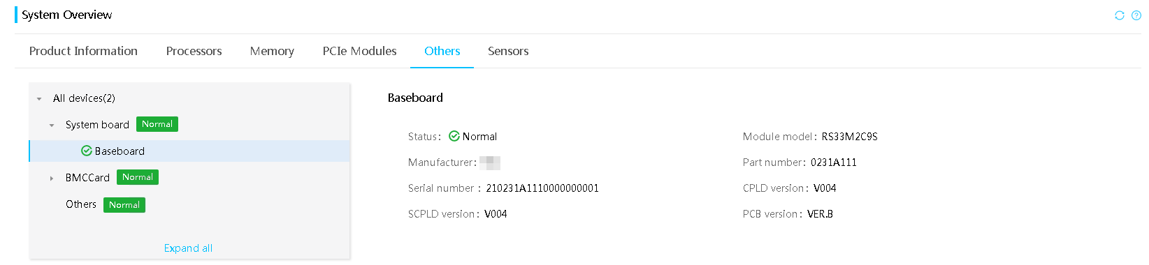
Parameters
· Status: Component health status. If a component is in abnormal state, review the event logs to locate the errors.
· Manufacturer: Manufacturer of the component.
· Part number: Part number of the component, which corresponds to the component model. This field displays N/A if HDM fails to obtain the part number.
· Serial number: Unique product code assigned by the manufacturer.
· CPLD1 version: Version of the primary CPLD firmware.
· CPLD2 version: Version of the secondary CPLD firmware.
· PCB version: Version of the Printed Circuit Board (PCB) firmware.
· Chip vendor: Manufacturer of the BMC chip.
· Chip model: Model of the BMC chip.
· Module model: Model of the module.
· Current firmware version: Firmware version of the drive backplane.
· Current configuration file version: Configuration file version of the drive backplane.
· Bootloader version: Bootloader version of the drive backplane.
· EEPROM version (for firmware): Electrically erasable programmable read only memory (EEPROM) version of the drive backplane.
· Fault description: Event log information about errors on the components.
· DSDCard: The server is installed with a dual-SD module. The module supports operating system installation and some serial port functions.
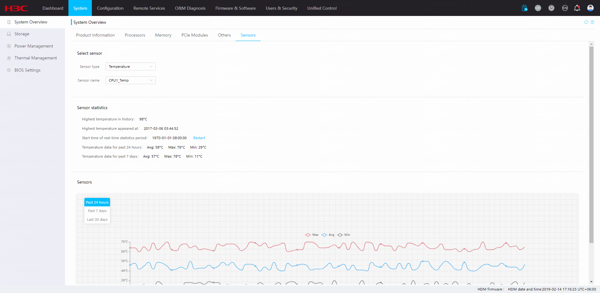
View the sensor reading chart
Perform this task to view the sensor readings in a line chart.
The system collects sensor readings at intervals of 5 minutes.
Restrictions and guidelines
HDM cannot obtain the sensor readings during restart.
Restoring HDM settings clears the sensor reading statistics.
Only linear sensors support this feature.
Some servers support displaying only the average sensor readings.
Disabling sensor prediction clears all sensor prediction data. Please be cautious.
Procedure
1. On the top navigation bar, click System.
You are placed on the Summary page.
2. Click the Sensors tab to view the corresponding information.
3. To view sensor readings on the Sensors tab, select a sensor type and name. You can perform the following tasks in the work pane:
¡ To clear the history readings and start a new statistics collection period, click Restart.
¡ To view sensor readings for the past 24 hours, past 7 days, or past 30 days in the line chart, select Past 24 hours or Past 7 days. You can hover over the lines in the chart to view the minimum, average, and minimum readings during the statistics collection period.
¡ To
view only the maximum, average,
or minimum sensor readings,
click the ![]() Max,
Max, ![]() Avg, or
Avg, or ![]() Min icon, respectively.
Min icon, respectively.
Figure 18 Viewing the sensor reading chart
Storage
The Storage menu allows you to perform the following tasks:
· View information about storage controllers, logical drives, physical drives, and storage errors.
· Manage storage controller information, including modifying RAID controller properties and clearing RAID configuration.
· Manage physical and logical drives controlled by the storage controller in Table 8 in an out-of-band manner:
|
Chip type |
Storage controller model |
HDM management channel |
|
LSI chip |
RAID-LSI-9560-LP-16i-8GB |
· Management Component Transport Protocol (MCTP) · Inter-Integrated Circuit (I2C) |
|
RAID-LSI-9560-LP-8i-4GB |
· MCTP · I2C |
|
|
HBA-LSI-9540-8i |
· MCTP · I2C |
|
|
HBA-LSI-9500-16i |
· I2C |
|
|
HBA-LSI-9500-8i |
· I2C |
|
|
PMC chip |
RAID-P460-B2 |
· MCTP · PMC BMC Services Interface (PBSI) |
|
RAID-P460-B4 |
· MCTP · PMC BMC Services Interface (PBSI) |
|
|
RAID-3254-8i |
· MCTP · PMC BMC Services Interface (PBSI) |
|
|
HBA-H460-B1 |
· PMC BMC Services Interface (PBSI) |
|
|
RAID-P4408-Ma-8i-2GB |
· MCTP |
|
|
RAID-P4408-Mr-8i-2GB |
· MCTP · PBSI (PMC BMC Services Interface) |
|
|
RAID-P2404-Mf-4i-2GB |
· MCTP · PBSI (PMC BMC Services Interface) |
|
|
MARVELL |
RAID-MARVELL-M.2 |
· I2C |
View storage summary information
1. On the top navigation bar, click System.
2. In the left navigation pane, select Storage.
3. View storage summary information, including the health status of the storage system, the numbers of storage controllers, logical drives, and physical drives, and fault descriptions.
If the health status is abnormal, check the fault descriptions and review the event logs to locate the errors. The fault description field can display a maximum of 1 to 511 characters. If a description exceeds 511 characters, access the event log page to view the complete information.
Figure 19 Viewing storage summary information

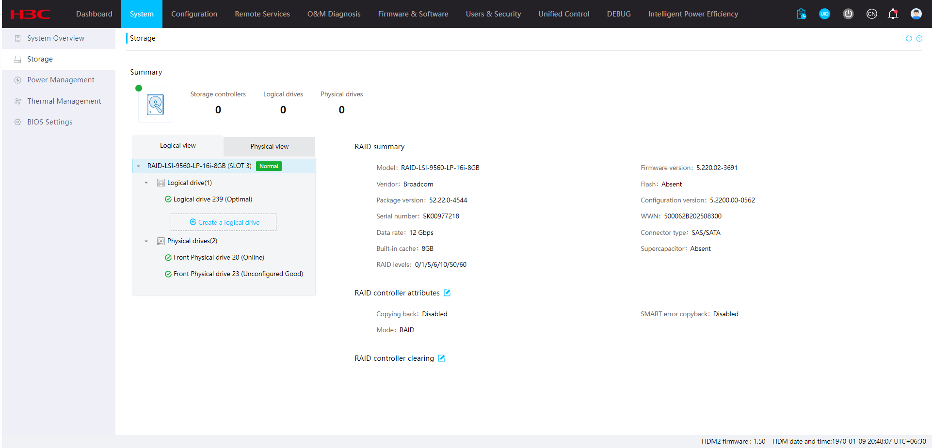
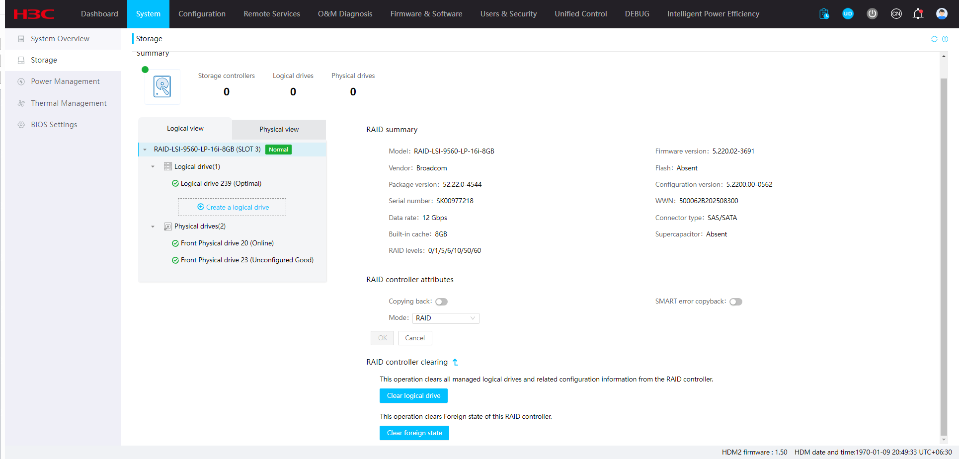
View storage controller information
Perform this task to view information about storage controllers, modify storage controller attributes, and clear RAID configuration.
Restrictions and guidelines
Refresh the Storage page to obtain the update-to-date storage information after the server OS starts up successfully.
If the storage controllers or drive backplanes are not installed as expected, the physical drive numbers might be incorrect.
After you change the RAID controller mode, the new mode takes effect after you restart the BIOS.
The RAID-P460-B2 storage controller supports obtaining information by using the MCTP or PBSI channel. You can switch the channel by configuring OOB Interface on the BIOS Setup utility.
· If you select MCTP channel, for HDM to obtain controller information, set SMBus Physical Channel to Disable for the channel.
· If you select PBSI channel for HDM to obtain controller information, set SMBus Clock Stretching to Enable for the channel.
Viewing storage controller information
1. On the top navigation bar, click System.
2. In the left navigation pane, select Storage.
3. On the Logical view tab, select a storage controller.
Figure 20 Viewing storage controller information
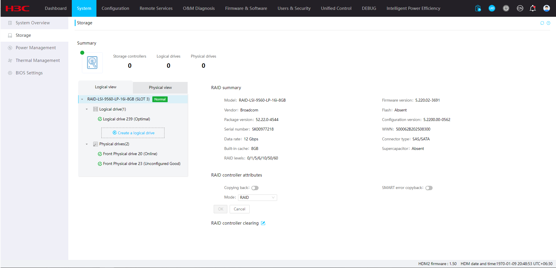
Modifying storage controller information
1. On the top navigation bar, click System.
2. In the left navigation pane, select Storage.
3. On the Logical view
tab, select a storage
controller, and click the ![]() icon next to RAID controller attributes. On the page that opens, you can perform the
following tasks:
icon next to RAID controller attributes. On the page that opens, you can perform the
following tasks:
¡ Enable or disable data copyback for the RAID controller.
¡ Enable or disable SMART error copyback for the RAID controller.
¡ Enable or disable JBOD for the RAID controller.
¡ Modify the RAID controller mode.
4. Click OK.
Figure 21 Modifying storage controller information
Clearing RAID configuration
1. On the top navigation bar, click System.
2. In the left navigation pane, select Storage.
3. On the Logical view
tab, select a RAID controller, and click the ![]() icon next to RAID controller
clearing. On the page
that opens, you can perform the following tasks:
icon next to RAID controller
clearing. On the page
that opens, you can perform the following tasks:
¡ Click Clear logical drive. In the dialog box that opens, enter the login password and click OK.
The system clears all managed logical drives and related configuration information from the controller once the password verification succeeds.
¡ Click Clear foreign state to clear the remaining RAID information for all physical drives managed by the controller. This feature is supported only for LSI RAID controllers.
4. Click OK.
Figure 22 Clearing RAID configuration
Parameters
Storage controller
· Device name: Model of the storage controller.
· Firmware version: Firmware version of the storage controller.
· Vendor: Manufacturer of the storage controller.
· Flash: Status of the flash card of the power fail safeguard module.
¡ For an LSI storage controller, status options include:
- Normal—The flash card is operating correctly.
- Abnormal—The flash card is operating incorrectly.
- Absent—The flash card is not connected to the supercapacitor, not installed securely, or not installed at all.
¡ For a PMC storage controller, status options include:
- Normal—The flash card is operating correctly.
- Absent—The flash card of the power fail module is not securely installed or is not installed at all.
- Initializing—The flash card is initializing.
- Abnormal_status code—The flash card is operating incorrectly. You can check the status code to identify the exceptions that cause the flash card to enter the abnormal state.
- Warning_status code—A warning is present on the flash card. You can check the status code to identify the exceptions that cause the flash card to enter the warning state.
A status code is a hexadecimal number. To identify the exceptions, convert the hexadecimal status code into a 16-digit binary number (bit 0 to bit 15 from the right to the left). A set bit means that the exception indicated by the bit is present. For information about a set bit and its corresponding exception, see Table 9.
For example, if the status code is 0x500 (binary format 0000 0101 0000 0000), exceptions indicated by bit 8 and bit 10 are present on the flash card.
Table 9 Flash card exceptions and their set bits
|
Bit# |
Bit state |
Description |
|
0 |
1 |
GB subsystem is currently initializing. |
|
1 |
1 |
GB subsystem is in ready state. |
|
2 |
1 |
GB subsystem is executing a learning cycle. Learning cycles do not disrupt normal operation or the ability to protect data. |
|
3 |
1 |
GB subsystem has failed. |
|
4 |
1 |
The supercapacitor pack has exceeded the maximum temperature threshold. |
|
5 |
1 |
The supercapacitor pack has exceeded the warning temperature threshold. |
|
6 |
1 |
The supercapacitor pack is over voltage. |
|
7 |
1 |
The supercapacitor pack has exceeded the maximum charging current. |
|
8 |
1 |
GB subsystem learning cycle has passed. |
|
9 |
1 |
GB subsystem learning cycle has failed. |
|
10 |
1 |
The supercapacitor pack has failed. |
|
11 |
1 |
The supercapacitor pack is nearing the end of its life. Replacement is recommended. |
|
12 |
1 |
The supercapacitor pack has reached the end of its life. Replacement is required. |
|
13 |
1 |
One of the capacitors in the supercapacitor pack seems to be missing. |
|
14 |
N/A |
Reserved. |
|
15 |
N/A |
Reserved. |
· Package version: Software package version of the storage controller. This field is available only for some LSI storage controllers.
· Configuration version: Configuration version of the storage controller.
· Serial number: Serial number of the storage controller.
· WWN: SAS address of the storage controller.
· Mode: Storage controller mode.
¡ For the LSI storage controller, supported options include RAID and JBOD.
¡ For the PMC storage controller, supported options include RAID, HBA, and Mixed.
· Data rate: Data rate supported by the connectors of the storage controller.
· Connector type: Connector type supported by the storage controller.
· Built-in cache: Capacity of the read/write cache embedded in the storage controller.
· Supercapacitor: Status of the supercapacitor. Options include Absent, Charging, Charge completed, Calibrating, Overtemperature, Calibration failure, and Abnormal. The supercapacitor is faulty when it is in Overtemperature, Calibration failure, or Abnormal state.
· Charging status: The remaining amount of power available with the supercapacitor.
· RAID levels: RAID levels supported by the storage controller. For PMC storage controllers, RAID1(Triple) and RAID10(Triple) are displayed as RAID1(ADM) and RAID10(ADM), respectively.
· Internal ports: Number of internal ports on a RAID controller.
· External ports:Number of external ports on a RAID controller.
· Clear foreign status: Clears remaining RAID information in physical drives. After you clear the information, the Foreign state disappears.
· Copyback: If a drive fails, the storage controller uses a hot spare drive to replace the failed drive and rebuilds data of the failed drive on the hot spare drive. When the storage controller detects that a new drive replaces the failed drive, it copies data on the hot spare drive back to the new drive and places the hot spare drive in standby status.
· SMART error copyback: When the storage controller detects that a Self Monitoring Analysis and Report Technology (SMART) error occurred to physical drives, it performs the copyback feature.
· JBOD: Enablement status of JBOD mode in the BIOS. This state enables data to be transmitted to physical drives without being processed by the transmission devices, and thus facilitates the upper-layer service software or management software in managing physical drives.
|
|
NOTE: The Flash and Charging status fields are available only if a power fail safeguard module is installed. A power fail safeguard module contains a flash card and a supercapacitor. When a system power failure occurs, this supercapacitor can provide power for a minimum of 20 seconds. During this interval, the storage controller transfers data from memory to the flash card, where the data remains indefinitely or until the controller retrieves the data. |
Manage logical drives
Perform this task to view logical drive information and create logical drives.
Restrictions and guidelines
After you create or delete a logical drive, wait a few moments for the system to complete the operation and then refresh the page to verify the operation result.
A physical drive can be used to create only one logical drive.
The default maximum capacity of a logical drive might be slightly different from the maximum capacity you can set. If you do not specify a drive capacity when creating a logical drive, the drive capacity is the default maximum capacity calculated by the system.
You can view and set the enablement status of JBOD mode from the BIOS only for some LSI storage controllers in RAID mode.
A storage controller can manage a maximum of 256 logical drives through HDM. Support for this feature varies by storage controller specification.
Procedure
1. On the top navigation bar, click System.
2. In the left navigation pane, select Storage.
3. On the Logical view tab, select a logical drive to view its information.
4. To modify the default read policy, default
write policy, cache policy, and access policy for drives managed by an LSI RAID
controller, click the ![]() icon.
icon.
5. To delete a logical drive, select the
logical drive, and then click the ![]() icon. In
the dialog box that opens, enter the user login password and click OK. HDM will
delete the logical drive and related configuration once the password
verification succeeds.
icon. In
the dialog box that opens, enter the user login password and click OK. HDM will
delete the logical drive and related configuration once the password
verification succeeds.
6. To create a logical drive, click Create a logical drive, specify drive parameters, and then click Save.
Figure 23 Logical drive information
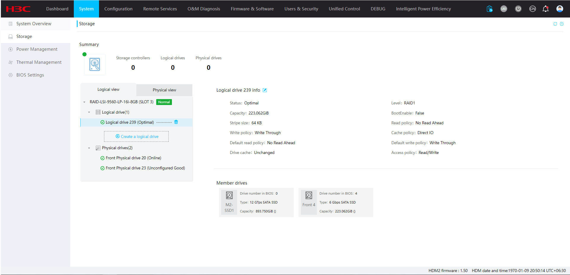
Parameters
· Name: Name of the logical drive. As a best practice, use letters and digits, and do not use special characters. For a PMC storage controller, this field is required and the name length is 1 to 31 characters. For an LSI storage controller, this field is optional and the name length is 0 to 15 characters.
· Status: Status of the logical drive. Options include:
¡ Optimal/Functional—The logical drive is operating correctly.
¡ Creating—The logical drive is being created.
¡ Degraded—Some RAID member drives have failed and require prompt replacement.
¡ Rebuilding—The RAID array is being rebuilt to reconstruct data and recover from the degraded state.
¡ Offline—The logical drive is corrupt and inaccessible.
¡ Zeroing—The logical drive is being formatted. All data will be deleted upon this action.
¡ Scrubbing—The member drives are being scanned to maintain data continuity in the logical drive. This field is available for logical drives with parity bits, such as RAID 5 and RAID 6 logical drives.
¡ Morphing—Data is being migrated between drives or the RAID array is changing to a new RAID level.
¡ Copying—Data is being copied from the hot spare disk back to the replacement drive of a failed drive. When this operation is complete, the hot spare returns to the hot standby state.
¡ Foreign—Indicates that the logical drive is in foreign status and has residual RAID information.
· BootEnable: Indicates whether the logical drive is a boot drive. Support for this field depends on the storage controller model. Options include:
¡ True—The logical drive is a boot drive.
¡ False—The logical drive is not a boot drive.
· Stripe size: Stripe size of each physical drive. Support for this field depends on the storage controller model.
· Read policy: Read policy for the logical drive. Support for this field depends on the storage controller model. Options are:
¡ No read ahead—Disables read ahead capability.
¡ Read ahead—Enables read ahead capability. When this capability is enabled, the storage controller can pre-read sequential data or anticipate data to be requested and store the data in the cache
· Write policy: Write policy for the logical drive. Support for this field depends on the storage controller model. Options are:
¡ Write through—Enables the controller to send a data transfer completion signal to the host when the drive subsystem has received all data in a transaction.
¡ Write back—Enables the controller to send a data transfer completion signal to the host when the controller cache receives all data in a transaction. If the storage controller is not installed with a supercapacitor or if the supercapacitor is faulty, the Write through policy is used.
¡ Always write back—Uses the Write back policy even if the supercapacitor of the storage controller is absent or faulty. If the server is powered off, the controller cache loses its data because of lack of power.
· Cache policy: I/O policy for the logical drive. Support for this field depends on the storage controller model. Options include:
¡ Direct—Enables the cache module to process all read and write operations of the storage controller.
¡ Cached—Disables the cache module from processing any read or write operations on the storage controller.
· Drive cache: Indicates whether drive cache is enabled for the logical drive. Support for this field depends on the storage controller model. Options include:
¡ Unchanged—The default drive cache policy is used.
¡ Enable—Drive cache is enabled.
¡ Disable—Drive cache is disabled.
· Access policy: Access policy for the logical drive. Support for this field depends on the storage controller model. Options include:
¡ Read/Write.
¡ Read only.
¡ Blocked.
· Acceleration method: Status of read/write cache. This field is available only for logical drives managed by a PMC storage controller that supports MCTP. Options include:
¡ Controller Cache—Enables read/write cache.
¡ None—Disables read/write cache.
¡ IO Bypass—Enables the storage controller to use I/O bypass paths to enhance read/write performance. This feature is available only on SSDs.
¡ MaxCache—Uses RAID created by SSDs to cache data to enhance read/write performance.
· Spans/Parity groups: Number of spans or parity groups for mixed-mode RAID (RAID 00, RAID 10, RAID 50, or RAID 60).
· Initialization type: Initialization type used upon logical drive creation. Options include:
¡ For a logical drive managed by an LSI storage controller:
- No—Does not initialize the logical drive.
- Fast—Initializes the first and last 10 MiB of the logical drive for data write upon drive creation, and then initializes the remaining space in background. The logical drive state changes to Optimal after initialization.
- Full—Initializes all space in the logical drive.
¡ For a logical drive managed by a PMC storage controller:
- Default—Does not initialize the logical drive.
- RapidParity—Initializes the first and last 10 MiB of the logical drive for data write upon drive creation, and then initializes the remaining space in background. The logical drive state changes to Optimal after initialization.
· Capacity: Drive capacity. For a logical drive managed by an LSI storage controller, the minimum capacity is 100 MiB. For a logical drive managed by a PMC storage controller, the minimum capacity is 1 GiB. If you do not specify a capacity, the maximum capacity is used.
· Dedicated hot spare: Dedicated hot spare disks for redundancy-capable logical drives. If a drive fails, the dedicated spare drive can replace the failed drive and rebuilds data of the failed drive on the hot spare drive. When the storage controller detects that a new drive replaces the failed drive, it copies data on the hot spare drive back to the new drive and places the hot spare drive in standby status.
· Roaming hot spare: Roaming hot spare disks for redundancy-capable logical drives managed by a PMC storage controller. If a drive fails, the roaming spare drive directly replaces the failed drive to become a member drive.
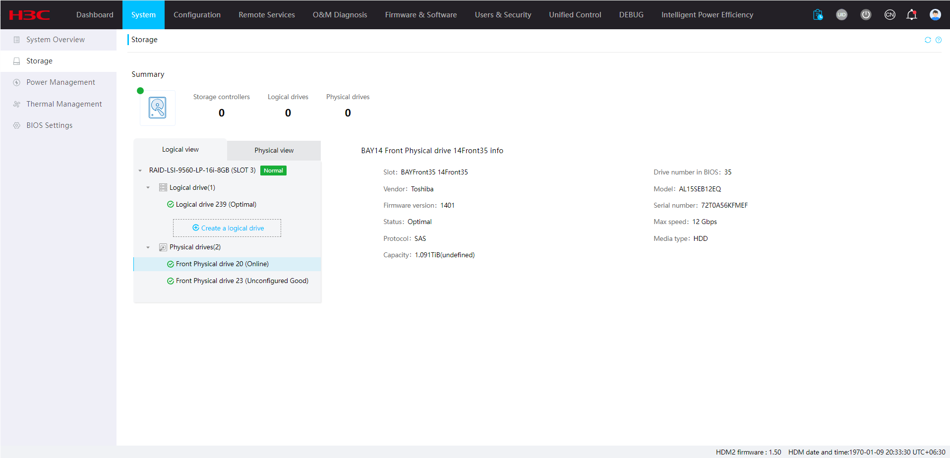
Manage physical drives
Perform this task to view information about physical drives, change drive status, and turn on the drive UID LED.
Restrictions and guidelines
If the drive status is Failed, the drive information might be inaccurate and is provided only for reference.
You cannot change the state of physical drives in Unconfigured Good (Foreign), Unconfigured Bad (Foreign), or Online state.
The Predicted remaining life field displays the value calculated by the system under the premise that the drives are operating stably. If drives are frequently read and written, the actual life of drives might change rapidly, resulting in deviations in the predicted remaining life of drives.
When you create hot spare drives, follow these restrictions and guidelines:
· Only spare physical drives can be used as hot spare drives, and member drives of logical drive cannot be configured to provide the hot spare service.
· Make sure the physical drive to be used is an SATA or SAS drive and its capacity is not smaller than the minimum capacity of a member drive. The physical drive must have the same type (SATA/SAS) as the member drives of the logical drive.
· You can create hot spares for logical drives of any RAID level, except for RAID 0.
· If an LSI storage controller is used, make sure the physical drive to use is in Unconfigured Good state. If a PMC storage controller is used, make sure the physical drive to use is in Ready state.
· You can only set one hot spare state for a physical drive at a time. If you want to change the hot spare state, disable the current state and then switch to the other.
· For a logical drive managed by a PMC storage controller, make sure all the hot spares are of the same hot spare state, and each hot spare can operate only in one state.
Procedure
1. On the top navigation bar, click System.
2. In the left navigation pane, select Storage.
3. To view information about a physical drive that has been used for creating logical drive:
a. On the Logical view tab, select a storage controller and a logical drive.
b. Select the physical drive.
c. To locate the drive, enable the drive UID LED. This feature is available only for some physical drives.
d. To change the
physical drive state, you can click the ![]() icon next to the physical drive name. If you set the drive state to dedicated
hot spare, you must select one or multiple target logical drives.
icon next to the physical drive name. If you set the drive state to dedicated
hot spare, you must select one or multiple target logical drives.
- Physical drives managed by an LSI storage controller support global hot spare and dedicated hot spare.
- Physical drives managed by a PMC storage controller support roaming hot spare and dedicated hot spare.
e. Click OK.
Figure 24 View physical drive information (logical view)
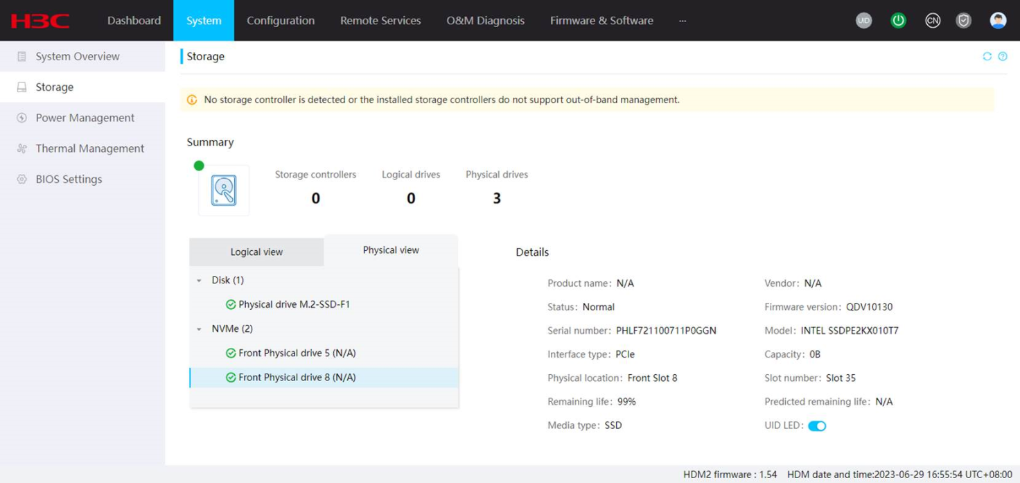
4. To view information about physical drives that are not used for creating logical drive:
a. Click the Physical view tab.
b. To locate the drive, enable the drive UID LED. This feature is available only for some physical drives.
c. To change the physical drive state, click
the ![]() icon next to the physical drive name. If
you set the drive state to dedicated hot spare, you must select one or multiple
target logical drives.
icon next to the physical drive name. If
you set the drive state to dedicated hot spare, you must select one or multiple
target logical drives.
- Physical drives managed by an LSI storage controller support global hot spare and dedicated hot spare.
- Physical drives managed by a PMC storage controller support roaming hot spare and dedicated hot spare.
d. Click OK.
Figure 25 View physical drive information (physical view)
Parameters
HDD and SSD drives
· Slot: Slot number of the physical drive.
· Drive number: Physical drive number.
· Vendor: Vendor of the physical drive.
· Model: Model of the physical drive.
· Firmware version: Firmware version of the physical drive.
· Serial number: Serial number of the physical drive.
· Status: Status of the physical drive. Options include:
If an LSI storage controller is installed, you can click Change status to change the physical drive state.
¡ Ready/Unconfigured Good/Unconfigured—The physical drive has been initialized or has not been configured, and it is available for RAID configuration and hot spare setting. The status name depends on the storage controller model.
¡ Unconfigured Bad—The physical drive is in abnormal state. To use the physical drive, you must change the physical drive state to Unconfigured Good. If an error has occurred on the physical drive, you will fail to change the physical drive state. In this case, you need to replace the faulty drive.
¡ Unconfigured Good (Foreign)—The physical drive has residual RAID information. After you clear residual RAID information, the physical drive state changes to Unconfigured Good.
¡ Unconfigured Bad (Foreign)—The physical drive has residual RAID information. After you clear residual RAID information, the physical drive state changes to Unconfigured Bad.
¡ Optimal/Online/Configured—The physical drive is already used to create a RAID. The status name depends on the storage controller model.
¡ Offline—The physical drive is disabled.
¡ Rebuilding—The physical drive is being used in RAID rebuilding.
¡ Hot spare—The physical drive is already used as a hot spare.
¡ JBOD/Raw—The physical drive is a passthrough drive, which can be used directly in the OS without RAID building.
¡ Failed—The physical drive failed.
¡ PFA—The physical drive is analyzing possible failures.
¡ Copyback—Data is being copied from the hot spare disk back to the replacement drive of a failed drive. When this operation is complete, the hot spare returns to the hot standby state. This field is available only for a physical drive attached to an LSI storage controller.
¡ Global hot spare—Acts as the spare for all qualified logical drives managed by an LSI storage controller. After the faulty drive recovers, data will be transmitted back to the drive from the hot spare, and the hot spare continues to operate in global hot spare state.
¡ Roaming hot spare—Acts as the spare for the specified logical drive managed by a PMC storage controller. After the faulty drive recovers, the new physical drive will act as the roaming hot spare.
¡ Dedicated hot spare—Acts as the spare for the specified logical drives. After the faulty drive recovers, data will be transmitted back to the drive from the hot spare, and the hot spare continues to operate in dedicated spare state.
· Rebuilding progress: Rebuilding progress of the physical drive in RAID rebuilding. This field is displayed for a physical drive only when the drive is in Rebuilding state.
· Type: Interface speed, interface type, and drive type of the physical drive. This field displays the negotiated speed, instead of the interface speed, for some storage controllers.
· Capacity: Capacity of the physical drive.
· Remaining life: Remaining SSD drive life in percent. This field is available only for the following drives when the drives are attached to an LSI storage controller that supports out-of-band RAID configuration:
¡ Intel SSD S4610 drives.
¡ Intel SSD S4600 drives.
¡ Intel SSD S4510 drives.
¡ Intel SSD S4500 drives.
¡ Intel SSD S3520 drives.
¡ Micron SSD 5200 drives.
¡ Samsung SSD drives.
· UID LED: Drive UID LED status. You can click this field to manage the drive UID LED.
NVMe drives
· Product name: Product name of the NVMe drive.
· Vendor: Manufacturer of the NVMe drive.
· Status: NVMe drive status:
¡ Normal—The NVMe drive is operating correctly.
¡ Abnormal—A PCIe err or Drive Fault error has occurred on the NVMe drive.
¡ Spare space below threshold—The available space in the NVMe drive has fallen below the threshold.
¡ Temperature anomaly—The NVMe drive temperature is above the upper threshold or below the lower threshold.
¡ Subsystem degraded—The NVMe subsystem reliability has been degraded because of storage media or internal errors.
¡ Read-only mode—The NVMe drive has been placed in read only mode.
¡ Cache failed—The volatile memory backup device has failed.
¡ Pre-alarm—The service life of the NVMe drive has reached the alarm threshold.
· Firmware version: Firmware version of the NVMe drive. This field displays N/A if HDM does not support displaying the firmware version of the NVMe drive.
· Serial number: Serial number of the NVMe drive.
· Model: Model of the NVMe drive.
· Interface type: Interface type of the NVMe drive.
· Capacity: Capacity of the NVMe drive.
· Physical location—NVMe drive slot number.
· Slot number—NVMe drive slot number or PCIe slot number assigned to the drive by the system.
· Max speed—Maximum speed supported by the NVMe drive.
· Remaining life: Estimate of the percentage of NVMe subsystem life used.
· Predicted remaining life(in days): Predicted remaining life of the NVMe drive in days.
· Media type: NVMe drive type. For NVMe drives, only the Solid State Disk (SSD) type is available.
· UID LED: Drive UID LED status. You can click this field to manage the drive UID LED. This field is available only when the drive is directly connected to the drive backplane.
Power management
Power on or power off the server
|
|
CAUTION: · The force power-off, force system reset, and force power-cycle actions might cause corruption or loss of data. When you perform these actions, make sure you fully understand their impact on the services. · With the physical power button disabled, you cannot perform power actions by pressing the power button on the chassis ear. |
Perform this task to power on or power off the server, disable the physical power button, or configure the power-on policy.
Powering on or powering off the server
1. On the top navigation bar, click System.
2. In the left navigation pane, select Power Management.
3. Click the Power status tab to view the current power status of the server.
4. To change the power status, click the desired action.
5. Select whether to enable or disable the physical power button as needed.
Figure 26 Powering on or powering off the server
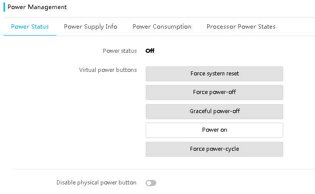
Configuring AC power recovery
1. On the top navigation bar, click System.
2. In the left navigation pane, select Power Management.
3. View the automatic power-on status.
4. Set the power-on delay time. If you select Random, you can customize the delay time range.
5. Click Save.
Figure 27 Configuring AC power recovery
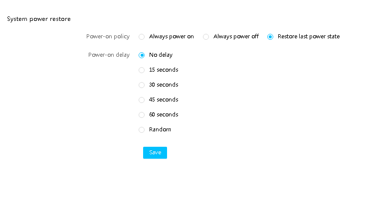
Parameters
· Force system reset: Warm reboots the server without power cycling the server.
· Force power-off: Shuts down the server immediately by force. This action is equivalent to pressing the power button on the server for five seconds.
· Graceful power-off: Shuts down the operating system first, and then removes power from the server.
· Power on: Starts up the server.
· Force power-cycle: Powers off and then powers on the server.
· Disable physical power button: Controls the physical power button. With the power button disabled, users cannot use the physical power button to manage the power status of the server.
· Power-on policy—Select whether to start the server when the server is connected to the power source. Options are Always power on, Always power off, and Restore last power state.
¡ To have the server always automatically start up when it is connected to the power source, select Always power on.
¡ To have the server stay off when it is connected to the power source, select Always power off.
¡ To have the server return to the power state on the previous power-off, select Restore last power state.
· Power-on delay—Set the power-on delay time. If you select Random, you can customize the delay time range.
View power supply information
Procedure
1. On the top navigation bar, click System.
2. In the left navigation pane, select Power Management.
3. Click the Power Supply Info tab.
4. View power supply summary and detailed information.
Figure 28 Viewing power supply information
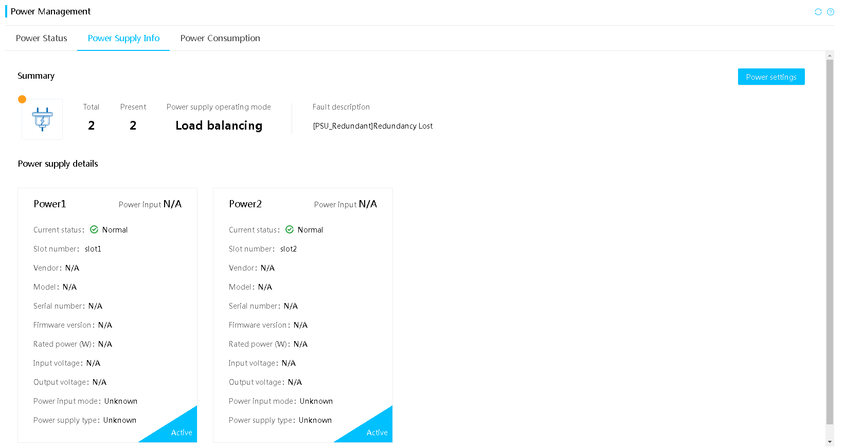
5. To view the input voltage history, click the
voltage icon ![]() .
.
Figure 29 View the input voltage history
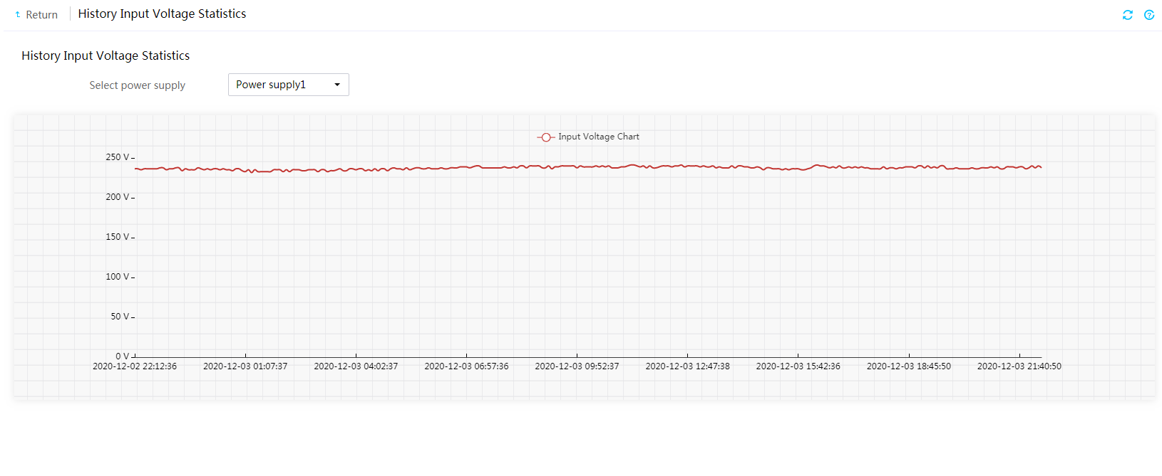
Parameters
· Power mode: Role of the power supply. Options include Active and Standby. The active power supplies provide power normally and the standby power supplies provide low power output.
· Power input: Input power of the power supply
· Current status: Status of the power supply. If a power supply is in abnormal state, review the event logs to locate the errors.
· Slot number: Number of the slot in which the power supply resides.
· Vendor: Manufacturer of the power supply.
· Model: Model of the power supply.
· Serial number: Unique code assigned by the manufacturer.
· Firmware version: Firmware version of the power supply.
· Rated power: Rated power of the power supply.
· Input voltage: Input voltage of the power supply.
· Output voltage: Output voltage of the power supply.
· Output power: Output power of the power supply.
· Power input mode: Power input mode. Options include:
¡ No input: The power supply is not connected to the power source.
¡ AC: The power supply is connected to an AC power source.
¡ HVDC: The power supply is connected to a high-voltage DC power source. The voltage is in the range of 192 V to 400 V.
¡ LVDC: The power supply is connected to a low-voltage DC power source. The voltage is in the range of 12 V to 72 V.
· Supported power input modes: Power input modes supported by the power supply. Options include:
¡ AC: The power supply supports only the AC input mode.
¡ AC or DC: The power supply supports both the AC and DC input modes.
¡ DC: The power supply supports only the DC input mode.
¡ Unknown: HDM has failed to obtain the power supply information.
· Fault description: Event log information about power supply errors.
Set the power supply operating mode
Restrictions and guidelines
Only the R4700 G6 and R4900 G6 servers support intelligent power saving.
To avoid configuration failure, set the power supply operating mode after the server starts up.
If you fail to set the operating mode for multiple power supplies in bulk, HDM generates a log message only for the power supply with the lowest slot number.
If the server has two power supply groups, you cannot set the power supply operating mode to active/standby for power supply group 2.
If Power Settings is unavailable, access the Intelligent Power Saving page and verify whether the power saving mode is enabled. Make sure you disable the power saving mode before configuring power settings.
To enable cold standby power supply monitor, make sure no health alarm exists for the power group and the group has two or more power supplies.
Cold standby power supply monitor can be enabled in both load balancing mode and active/standby mode.
Procedure
1. On the top navigation bar, click System.
2. In the left navigation pane, select Power Management.
3. In the work pane, click the Power Supply Info tab.
4. Click Power Settings.
5. Select the power supply operating mode and enable or disable cold standby power supply monitoring. Available operation modes include:
¡ Load balancing—Allows all power supplies to provide power in a balanced way.
¡ Active/standby—Allows active power supplies to mainly provide power. In this mode, you must specify a minimum of one active power supply and a minimum of one standby power supply. If an active power supply fails, a standby power supply becomes active to supply power. If an actual power consumption of the active power supply exceeds 62% of its maximum rated power consumption, a standby power supply becomes active to supply power. The active/standby switchover will not be performed after the power consumption of the original active power supply drops.
6. Click OK.
Figure 30 Setting the power supply operating mode
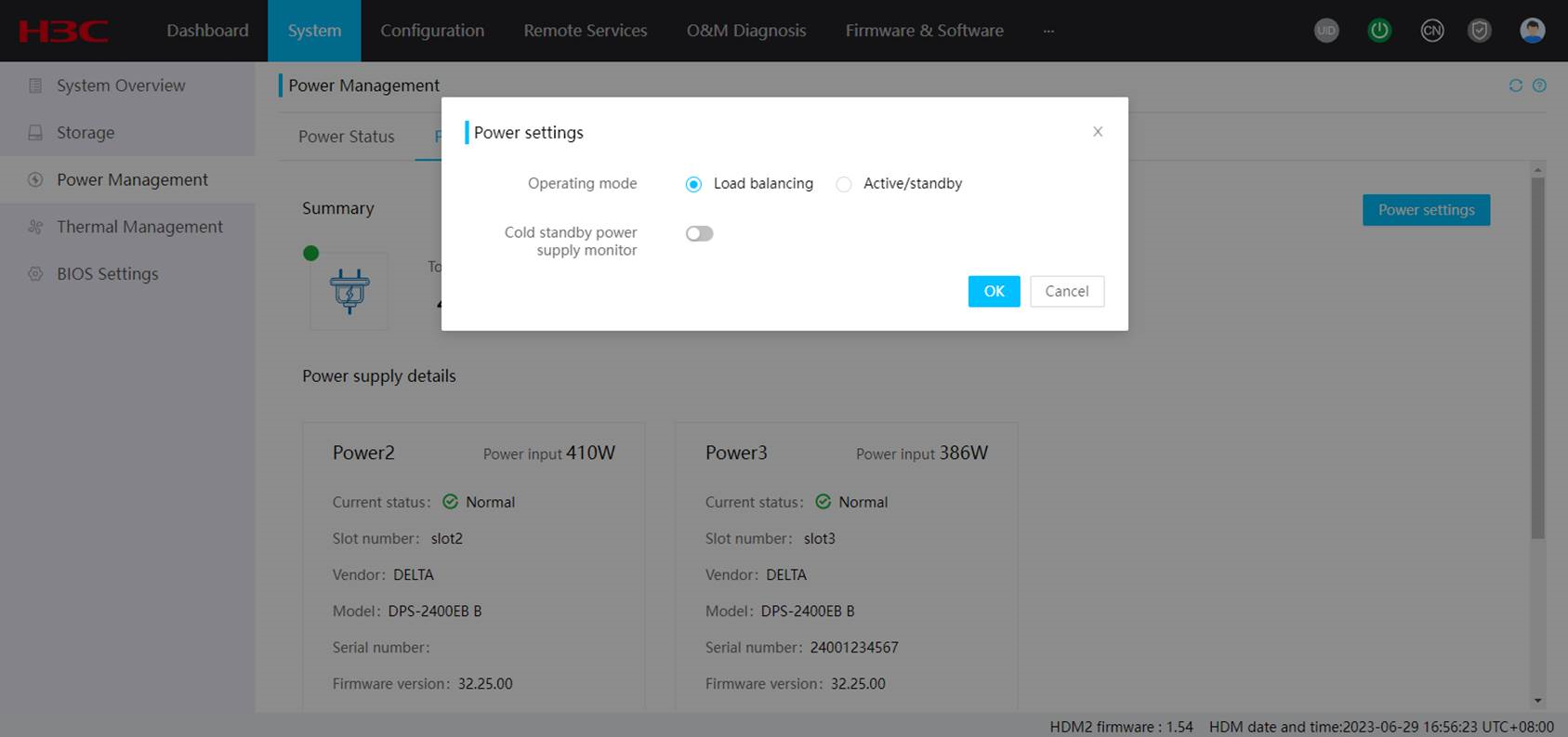
Parameters
Cold standby power supply monitor: Monitor if all the present cold standby power supplies in a power group can act as active power supplies to output power correctly. During the monitor, the system switches the power mode to load balancing and verifies whether the power output of the power group is correct.
· If the power output is correct, the system restores to the previous user-configured power mode.
· If the power output is incorrect, the power supplies keep operating in load balancing mode.
View power consumption information
Perform this task to view power consumption summary, power information, and power consumption history. You can view the 5-minute server power consumption statistics for the past 24 hours or seven days, including the maximum, average, and minimum power consumption.
Procedure
1. On the top navigation bar, click System.
2. In the left navigation pane, select Power Management.
3. In the work pane, click the Power Consumption tab.
4. View the power consumption summary, power alarming, system board power capping, CPU node power capping, GPU node power capping, and history power information.
¡ To clear the history readings and start a new statistics collection period, click Restart.
¡ To view power consumption in a time range, select a start time and end time, and then click OK.
¡ To
view only the maximum, average, or minimum power consumption, click the ![]() Max,
Max, ![]() Avg, or
Avg, or ![]() Min icon, respectively.
Min icon, respectively.
Figure 31 Power supply power information
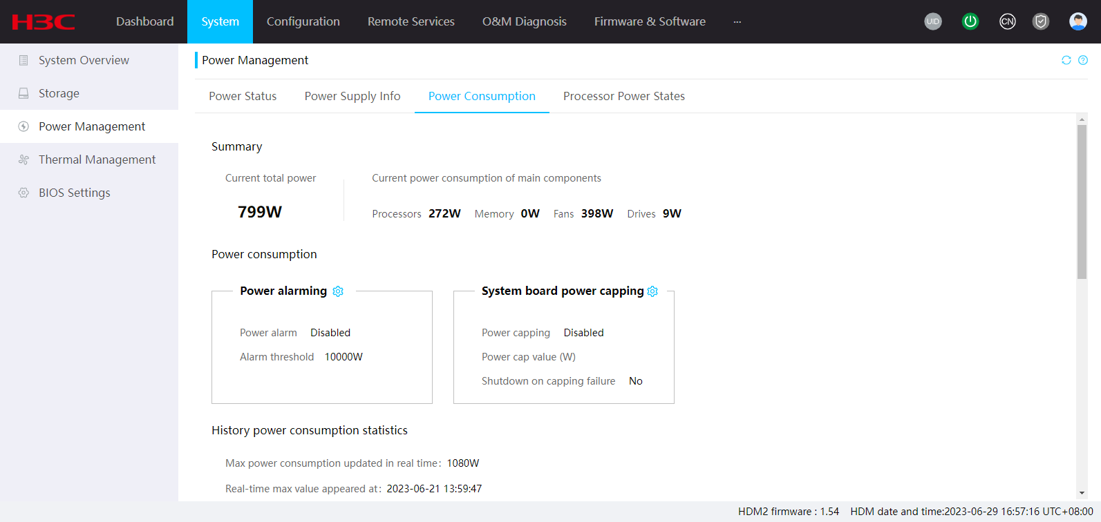
Figure 32 History power information
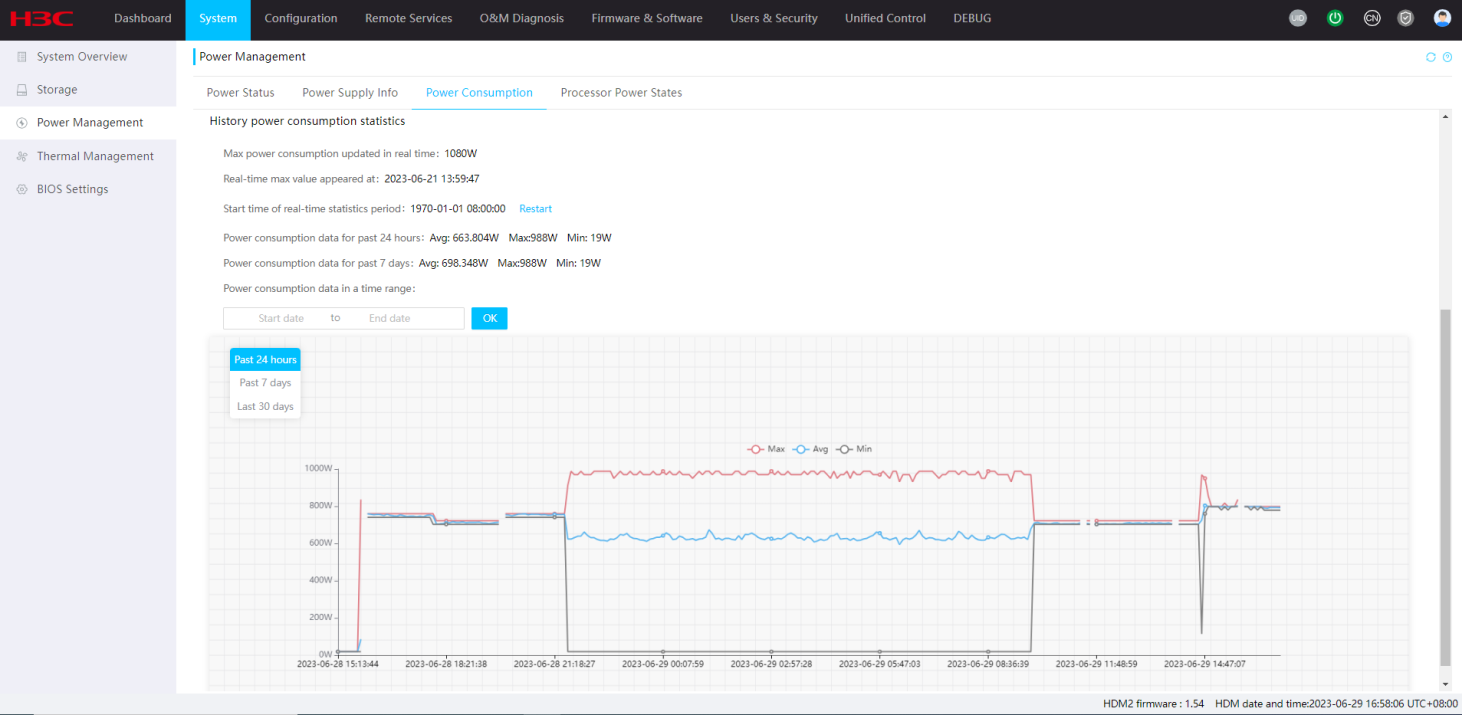
Configure power alarming
Power alarming allows the system to generate an alarm log when the total power consumption of the server exceeds the alarm threshold.
Procedure
1. On the top navigation bar, click System.
2. In the left navigation pane, select Power Management.
3. In the work pane, click the Power Consumption tab.
4. Click the ![]() icon
in the Power alarming section.
icon
in the Power alarming section.
5. In the dialog box that opens, enable power alarming and then specify the alarm threshold.
6. Click OK.
Figure 33 Configuring power alarming
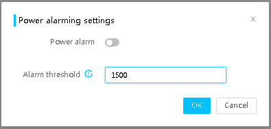
Configure power capping
Power capping limits the power consumption of the server to a power cap value that is lower or equal to the maximum rated power of the server.
When the power cap value of the system board or CPU node is exceeded, the server attempts to decrease power consumption by automatically decreasing the operating frequency of system components such as processors.
When the GPU node power cap value is exceeded, the server attempts to decrease power consumption by automatically decreasing the operating frequency of GPUs.
Power capping fails if the power consumption cannot drop below the power cap value in 30 seconds. You can configure the server to shut down or continue to run on a power capping failure.
Restrictions and guidelines
|
|
CAUTION: Server shutdown upon a power capping failure causes service interruption. To use this function, make sure you understand the impact. |
Only the R5500 G6 server supports setting CPU node power capping and GPU node power capping.
Power capping is at the expense of system performance. Select the power cap value carefully to avoid undesirable decrease in performance.
To avoid GPU node power capping configuration invalidity, make sure the GPU driver is installed in the OS before configuring GPU node power capping settings.
Set reasonable power cap values. If a power cap is too low, power capping failures might occur.
During HDM restart and the server shutdown period, the system cannot record historical power information.
If HDM is restored to its factory settings, all historical power information will be deleted.
Only the system board and CPU nodes support configuring the action to take upon a power capping failure.
Procedure
1. On the top navigation bar, click System.
2. In the left navigation pane, select Power Management.
3. In the work pane, click the Power Consumption tab.
4. Click the ![]() icon
in the System board power capping, CPU node, or GPU node section.
icon
in the System board power capping, CPU node, or GPU node section.
5. In the dialog box that opens, enable power capping, set the power cap value, and then set the action to take upon a power capping failure.
6. Click OK.
Figure 34 Configuring power capping
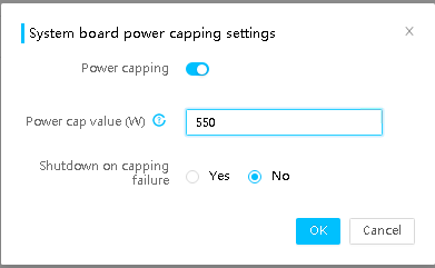
Configure processor power states
Perform this task to configure the processor power states and the power supply operating mode.
You can adjust the power consumption of processors by changing the processor power states.
Restrictions and guidelines
The AMD platform, such as the R4950 G6 and R5350 G6, does not support configuring processor power states.
Prerequisites
For the power states to take effect, configure the following tasks on the Socket Configuration > Advanced Power Management Configuration screen from the BIOS:
1. Set EIST (P-States) and Software Controlled T-States to Enabled.
2. Select the T-state throttle level.
3. Set Hardware P-States to Disable.
4. Set Power Performance Tuning to BIOS Controls EPB.
Then, save the configuration and restart the host.
Restrictions and guidelines
The adjusted P-state takes effect immediately after you save the configuration and the P-state restores to the default after the server restarts.
After saving the CPU power-efficient configuration, you must restart the server for the configuration to take effect. If you configure CPU power-efficient settings when BIOS is starting up, the settings will not take effect. Do not configure CPU power-efficient settings at BIOS startup.
Procedure
1. On the top navigation bar, click System.
2. In the left navigation pane, select Power Management.
3. Click the Processor Power States tab.
4. Click Advanced Settings.
5. Adjust the preferred P-state value and then click OK.
The available state values vary by processor model.
6. Select the power supply operating mode, and then click Save. The operating mode options include:
¡ Performance—Indicates the performance first mode.
¡ Balanced—Indicates the balanced performance and power consumption mode.
¡ Power—Automatically adapts the speed and energy consumption of the processors according to processor usage. This mode reduces the total consumption and has little or no impact on the performance.
Figure 35 Configuring power saving
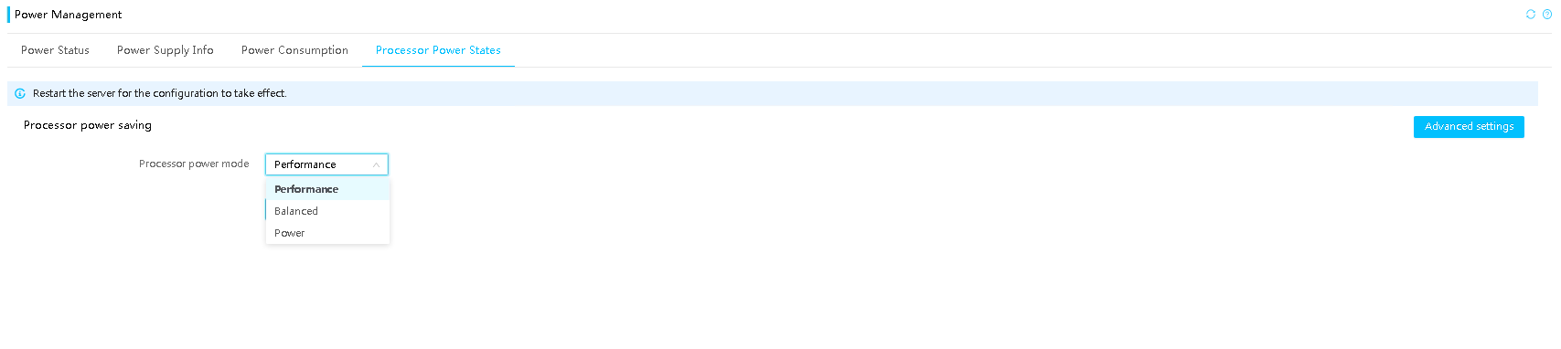
Parameters
P-state: Defines the operating frequency of processors. A smaller P-state value represents a higher operating frequency, which translates to higher performance and higher power consumption.
Thermal management
View status and readings of temperature sensors
HDM presents temperature data in both heatmap and table formats to help you monitor the cooling performance of the server.
· The temperature heatmaps use colors between green and red to show the temperature distribution inside the server chassis in 2D and 3D views and use circles to represent sensors. Green indicates 0°C (32°F). As the temperature gets higher, the color gets warmer until it changes to red. With the temperature heatmaps, you can quickly identify the component that is in a poor cooling condition.
· The temperature sensor table displays the temperature reading, status, and coordinates of each sensor.
Restrictions and guidelines
The temperature heatmaps do not display sensors whose reading is negative.
Procedure
1. On the top navigation bar, click System.
2. In the left navigation pane, select Thermal Management.
3. View the temperature heatmap and sensor list.
Figure 36 Viewing status and readings of temperature sensors
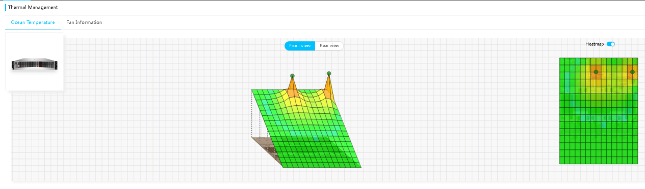
Parameters
· Status: Temperature status of a component:
¡ Normal—The temperature is normal, between the lower and upper minor thresholds (exclusive). No action is required.
¡ Minor—The temperature is between the lower major threshold (exclusive) and lower minor threshold (inclusive) or between the upper minor threshold (inclusive) and upper major threshold exclusive). Administrative attention is required.
¡ Major—The temperature is between the lower critical threshold (exclusive) and lower major threshold (inclusive) or between the upper major threshold (inclusive) and upper critical threshold (exclusive). Immediate action is required.
¡ Critical—The temperature is equal to or below the lower critical threshold, or it is equal to or above the upper critical threshold. Immediate action is required.
¡ N/A—The monitored component is not installed or the temperature sensor cannot be read.
· Reading: Current temperature. If HDM fails to read the sensor, this field displays N/A.
· Thresholds: Temperature thresholds:
¡ Critical—Lower and upper critical thresholds. When the temperature reaches either threshold, the server might automatically shut down to avoid damage to its components.
¡ Major—Lower and upper major thresholds. If the temperature reaches either threshold, server performance will significantly degrade.
¡ Minor—Lower and upper minor thresholds. If the temperature reaches either threshold, server performance will slightly degrade.
Manage fans
Perform this task to view fan information and fan errors and configure the fan speed mode.
You can adjust the fan speed mode to optimize the cooling, noise control, and energy efficiency performance.
Set the preferred fan speed mode
1. On the top navigation bar, click System.
2. In the left navigation pane, select Thermal Management.
3. View fan information.
4. Click Fans.
5. Select a fan speed mode.
6. Click OK.
Figure 37 Viewing fan information
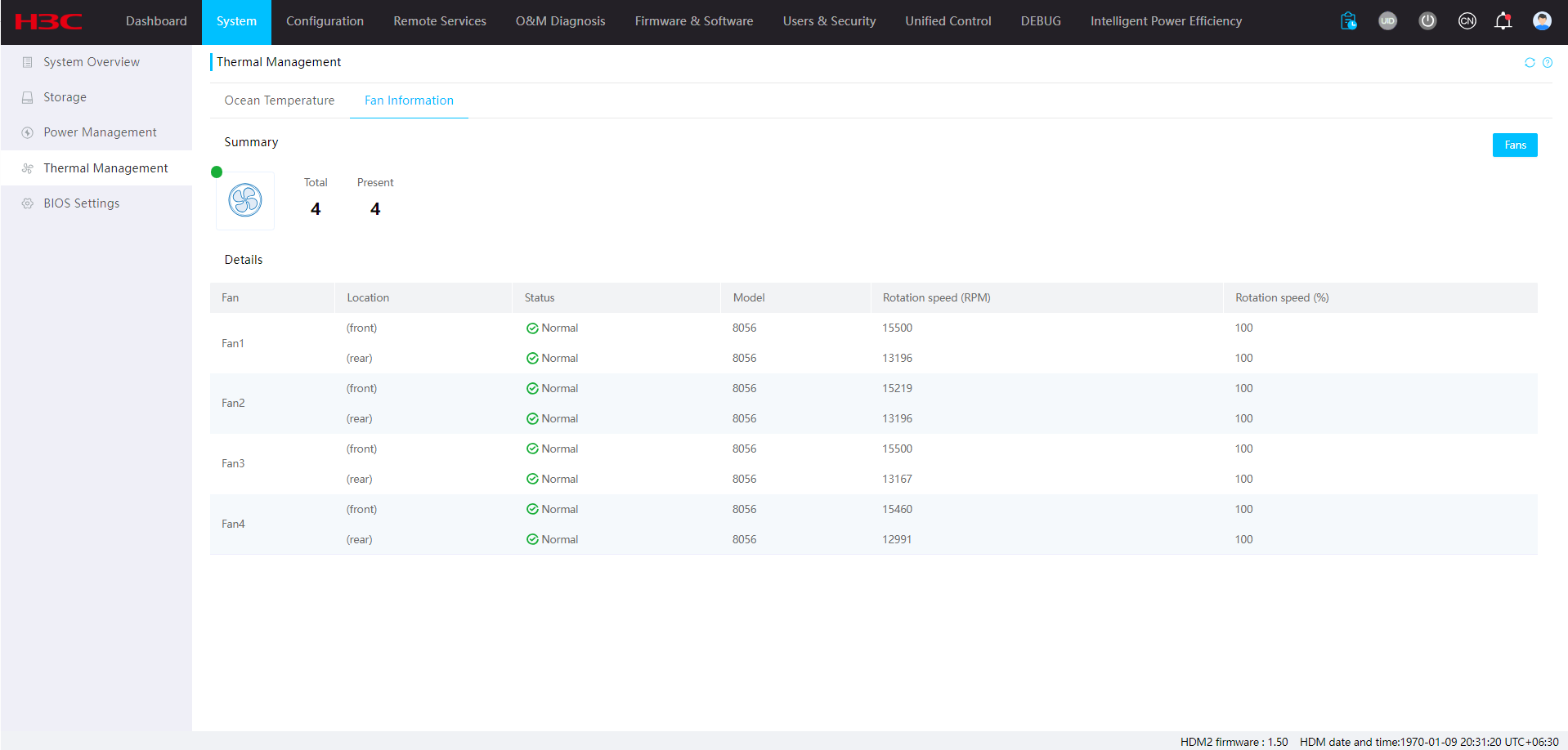
Figure 38 Managing fans
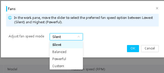
Parameters
· Location: If a fan contains two rotors or a fan module contains two fans, this field displays the location of a rotor or a fan.
· Status: Operation status of the fan.
· Model: Fan model.
· Rotation speed (RPM): Current actual rotational speed.
· Rotation speed (%): Ideal RPM based on current temperature as a percentage of the rated RPM.
· Fault description: Alarms generated for fan errors.
· Silent: Enables the fans to run at the lowest speed required by heat dissipation of the server. This mode is suitable for scenarios with high noise requirements.
· Balanced: Enables the fans to run at a higher speed to provide balanced noise control and cooling performance.
· Powerful: Enables the fans to run at the highest possible speed. This mode is suitable for scenarios where the server requires high cooling performance. For example, the server is busy and key components, such as processors, are heavily loaded, or the ambient temperature changes frequently.
· Custom: Specifies a customized fan speed level. A higher level represents a higher speed and larger noise.
BIOS settings
Restrictions and guidelines
Items for the BIOS settings are only available in English.
If you configure the BIOS settings when BIOS is starting up, the settings will not take effect. Do not configure the BIOS settings at BIOS startup.
Procedure
1. On the top navigation bar, click System.
2. In the left navigation pane, select BIOS Settings.
3. Click the target tab, and configure the BIOS settings.
4. To view explanation for an item, hover over
the ![]() icon.
icon.
5. Click Save. The new configuration takes effect at next startup.
6. To cancel the settings that have not been saved, click Cancel.
7. To clear the preset settings to be applied, click Remove all preprovisioned settings. After clearing, the preset settings do not take effect at next startup.
Figure 39 BIOS settings
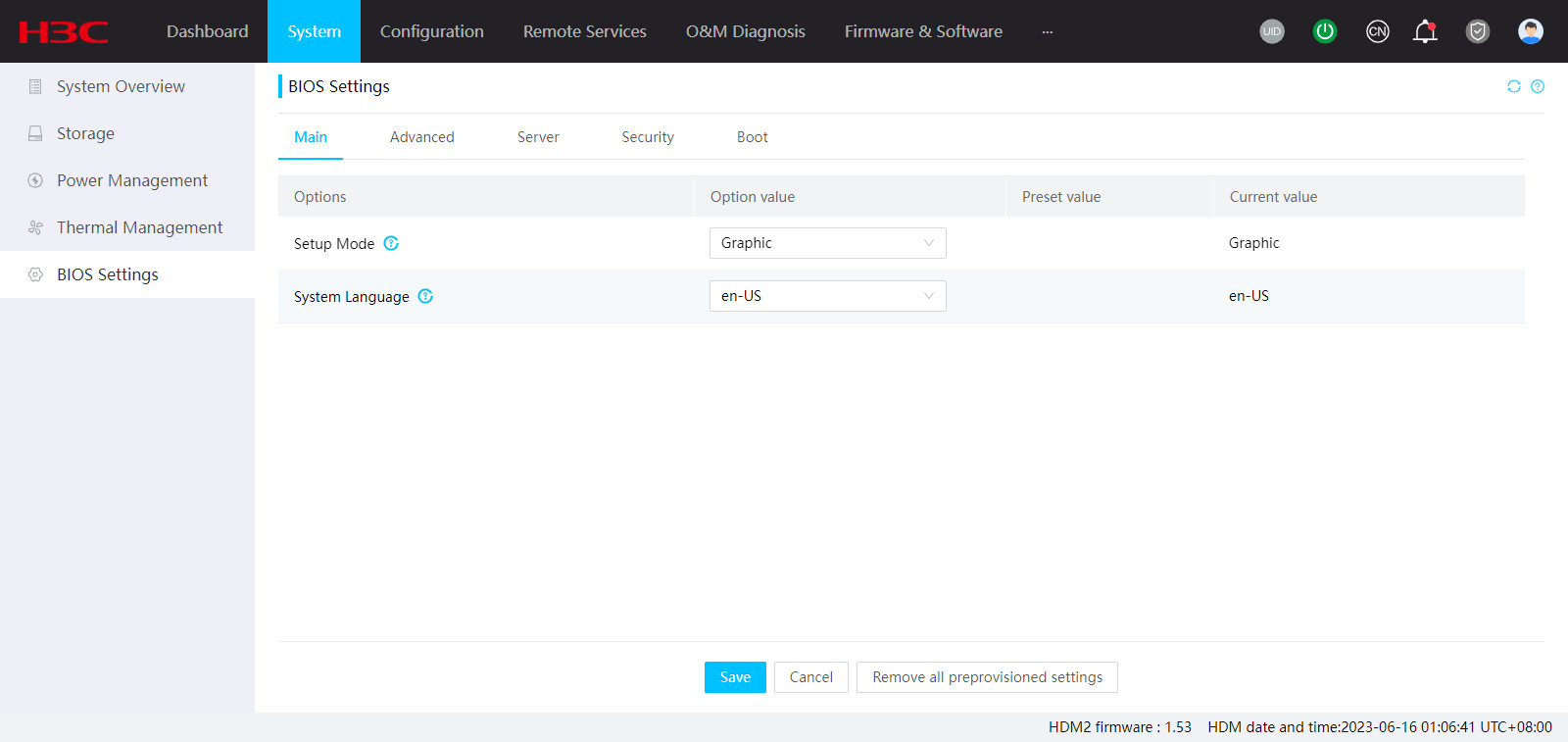
Parameters
· Options: The BIOS options to be configured.
· Option value: Value of an available option.
· Preset value: Settings to be applied by the user. The preset settings take effect at next startup.
· Current value: Option value at the most recent startup.
Boot option configuration
This feature allows you to configure the boot mode and boot option for the server.
Restrictions and guidelines
· This feature is available only for servers installed with Intel processors.
· If the boot option validity is set to Permanent, you cannot set the next boot mode and the next boot option as None at the same time.
· Some servers do not support configuring the validity period for boot options and only allow the boot options to take effect once at next startup.
· The displayed sub-boot option configuration parameters depend on the obtained boot information.
· If you select to boot the system from the hard disk in Legacy mode, make sure the hard disk supports the Legacy mode.
· The sub-boot option configuration is not supported in Legacy mode.
· The boot option configuration might not take effect if you configure it at the BIOS startup stage.
Procedures
Configure boot option settings
1. On the top navigation bar, click System.
2. In the left navigation pane, select Boot Option Configuration.
3. Set the validity period to One time or Permanent.
4. Select the next boot mode and next boot option.
5. Configure the boot order.
¡ To
increase the boot priority of an option, select the option and click the ![]() icon.
icon.
¡ To
lower the boot priority of an option, select the option and click the ![]() icon.
icon.
¡ To
reset the boot order settings, click the ![]() icon.
icon.
6. View the current boot mode and current first boot option.
7. Click Save.
Configure sub-boot option settings
1. On the top navigation bar, click System.
2. In the left navigation pane, select Boot Option Configuration.
3. In the Sub-boot option configuration area, select a boot option.
4. Adjust the sub-boot option order.
¡ To
increase the boot priority of a
sub-boot option, select the sub-boot
option and click the ![]() icon.
icon.
¡ To
lower the boot priority of a
sub-boot option, select the sub-boot
option and click the ![]() icon.
icon.
5. Click Save.
Parameters
Boot option configuration
· One time: The boot option configuration only takes effect once at next startup. After the next startup, the boot option configuration will be restored to the default.
· Permanent: The boot option configuration takes effect permanently.
· Next boot mode: Select the next boot mode for the server. Options include Legacy, UEFI, and None. The None configuration indicates that no modification is made to the server boot mode and the server will start with the boot mode configured in the BIOS.
· Next boot option: Configure the first boot option at next startup. The None configuration indicates that no modification is made to the server boot option and the server will start with the boot order configured in the BIOS.
· Boot order: Configure the boot order. Other Device indicates other boot options, including:
¡ Unidentified boot devices.
¡ Embedded UEFI shell. This option is available only when EFI Shell Boot is set to Enabled in the BIOS.
Sub-boot option configuration
· Boot option: Select the boot option to be configured.
· Sub-boot option order: Configure the sub-boot option order. The device will start from the first sub-boot option at next startup.
HDM Configuration
Network
You can log in to HDM from the HDM dedicated network port or the HDM shared network port.
The dedicated network port can process only HDM management traffic. By default, the dedicated network port uses IPv4 address 192.168.1.2/24 and obtains an IPv6 address from the DHCP server.
The shared network port transmits HDM management traffic and server data traffic simultaneously. By default, the shared network port automatically obtains its IP address through DHCP.
General restrictions and guidelines for network configuration
To ensure successful access to HDM, follow these restrictions and guidelines when you configure network settings:
· If the HDM dedicated network port and shared network port are in normal mode, make sure the dedicated port, shared port, and the WLAN use different IP addresses from different subnets. A violation might cause network failure.
· Do not disable the HDM dedicated network port and the shared network port at the same time. HDM Web interface will be inaccessible if both network ports are disabled.
· Any change to network settings can cause HDM user sessions to disconnect and take a few minutes to take effect. After you change network settings, reconnect to the HDM Web interface at prompt.
· If you need to power off the server after changing network settings, first wait for the changes to take effect.
General configuration
Restrictions and guidelines
Verify that the network interface to be used as the shared network port is in up state before manually changing the shared network port.
The change of the shared network port does not require reconfiguring port network settings. All the network settings except for the IP address obtained through DHCP continue to take effect after the change. If the IP address of the HDM shared port is obtained through DHCP, the DHCP server re-assigns an IP address to the shared network port after you change it.
If you disable automatic shared port selection and do not specify an interface as the shared port, the system uses the shared port specified before you enabled the feature. Make sure the port is in up state. If the port is in down state, HDM will be inaccessible.
Before importing a configuration file to edit network port selection and network port mode, make sure the file content is intact and correct.
Aggregate links are used once you enabled the automatic shared port selection.
If you use one NCSI cable to connect two network adapters to the server, HDM only displays information about the connected network adapter.
Configure the host name
1. On the top navigation bar, click Configuration.
You are placed on the Network page.
2. In the Set hostname section, select Manual or Auto configuration for the host.
¡ If you select manual configuration, enter the host name manually.
¡ If you select automatic configuration, the host name is set to HDM+serial_number by default.
3. Click Save.
Figure 40 Configuring the host name

Connect HDM to a network
1. On the top navigation bar, click Configuration.
You are placed on the Network page.
2. In the Connection config section, select the network mode from Normal mode and Active/Standby mode.
¡ If you select normal mode, you can select whether to enabled HDM shared network port. After enabling, you can view the status of the automatic network adapter selection, and configure the automatic shared port selection or specify the port manually.
¡ If you select active/standby mode, the shared network port is enabled automatically for accessing HDM once the dedicated port fails, and cannot be disabled. After enabling, you can view the status of the automatic network adapter selection, and configure the automatic shared port selection or specify the port manually.
3. Click Save.
Figure 41 Connecting HDM to a network
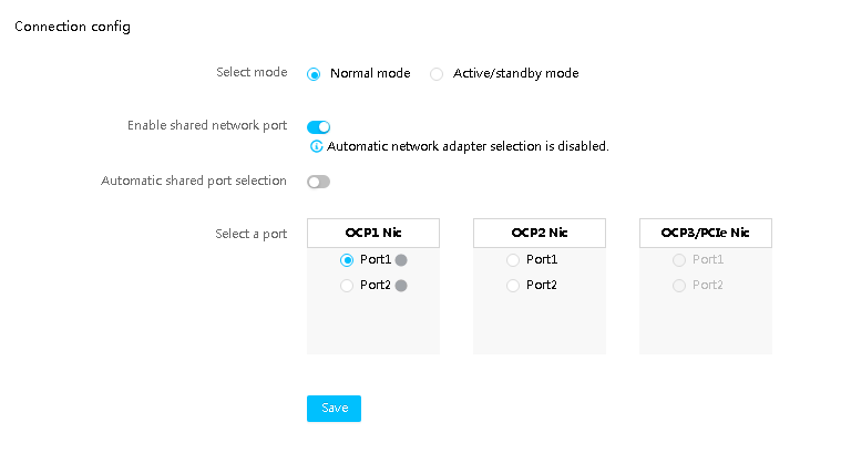
Parameters
· Host name: Name of the HDM host, a string of 1 to 63 characters. For special characters, only hyphens (-) are allowed but the string cannot start or end with a hyphen (-).
· Normal mode—The HDM dedicated and shared network ports have separate IP addresses and operate in active/active mode. HDM is accessible at both ports. This is the default mode.
· Active/standby mode—The HDM dedicated and shared network ports have separate IP addresses and operate in active/standby mode. In this mode, the dedicated port is the primary port and the shared network is the secondary port. HDM is accessible at the dedicated port as long as the dedicated port is up and has network connectivity. After the dedicated port fails, HDM is accessible at the shared port. In standby mode, the shared port cannot forward management traffic, but it can still forward data traffic.
View dedicated network port information
Perform this task to view information about the dedicated network port, including MAC address, connection status, IPv4 and IPv6 addresses, VLAN settings, and self-negotiation settings.
Procedure
1. On the top navigation bar, click Configuration.
You are placed on the Network page.
2. On the Dedicated Port tab, view information about the dedicated network port.
3. (Optional.) To view the state of an address, hover over the icon before the link local address or IPv6 address. Available states include Pending, Failed, and Active.
Figure 42 Viewing dedicated network port information
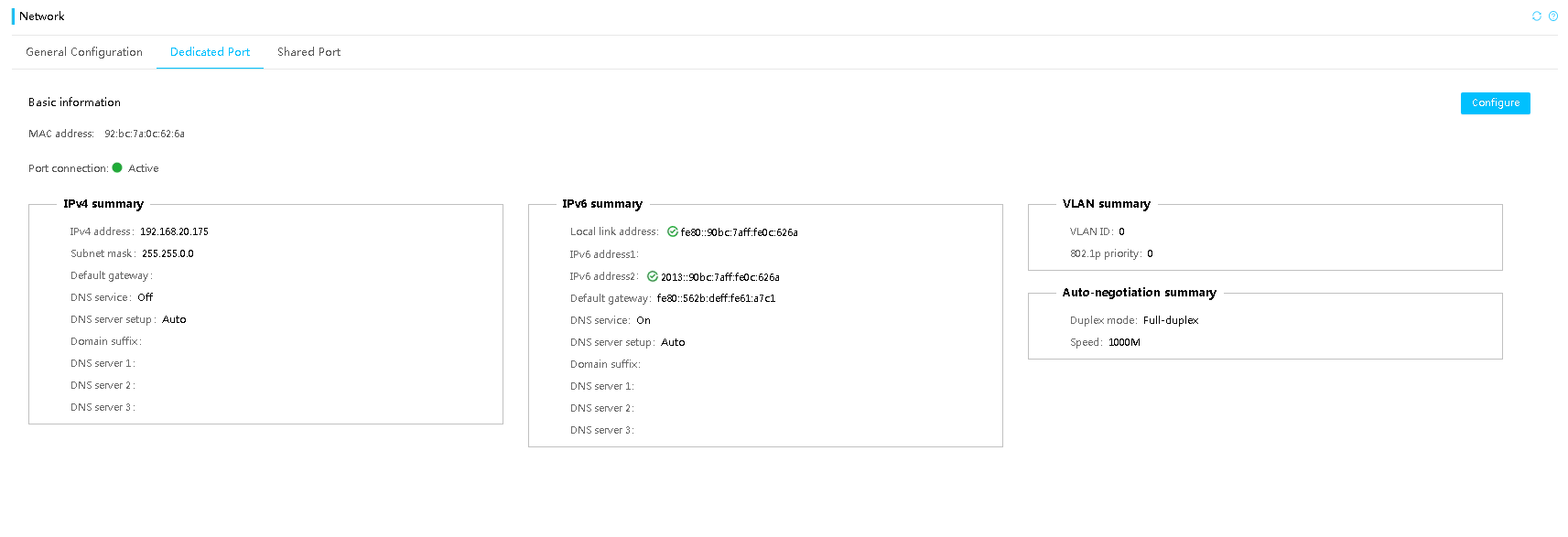
Parameters
· Port state: This field is available only when the network port mode is active/standby. Options include:
¡ Active—The port is connected and in active state.
¡ Disconnected—The port is disconnected.
· Port connection: Displays whether a cable is connected to the port. Options include:
¡ Disconnected—The port is disconnected.
¡ Active—The port is connected and is in active state.
Configure the dedicated network port
Perform this task to configure information about the dedicated network port, including MAC address, connection status, IPv4 and IPv6 addresses, VLAN settings, and self-negotiation settings.
Domain Name System (DNS) is a distributed database used by TCP/IP applications to translate domain names into IP addresses. You can configure DNS to enable access to HDM by using a domain name instead of the management IP address of HDM.
Restrictions and guidelines
See "General restrictions and guidelines for network configuration."
An IPv6 address assigned by the DHCP server or configured through stateless autoconfiguration supports only the 64-bit prefix.
If you cannot log in to HDM at its IPv6 address, disable proxy server in the browser and then try again.
If you are manually specifying IPv6 addresses of DNS servers, specify global IPv6 addresses.
If an invalid DNS server address is configured, the DNS registration might take a long time.
DNS is configurable only when the corresponding IPv4 or IPv6 network service is enabled.
The DNS configuration might change only when the following conditions are met:
· The obtaining method of an IPv4 or IPv6 address changes from DHCP server assignment to manual configuration.
· The Configure DNS service field is Auto.
In this case, the Configure DNS service field will switch to Manual automatically and the system will continue to use the domain suffix and DNS server information before the switch.
After disabling IPv6 configuration, you can still use the IPv6 link-local address.
Prerequisites
Verify that the dedicated network port is physically connected to the network.
Configure IPv4 settings
1. On the top navigation bar, click Configuration.
You are placed on the Network page.
2. On the Dedicated Port tab, click Configure.
3. Select Enable for IPv4 to enable IPv4 network service.
4. Configure IPv4 address settings for the port:
¡ To use the IP address automatically assigned by a DHCP server, select Automatic IP obtaining.
¡ To manually configure static IP address settings, clear Automatic IP obtaining, and then enter an IPv4 address, subnet mask, and default gateway address.
5. In the Configure DNS service area, select Enable for DNS service.
6. Select Manual, or IPv4 (Auto) from the Configure DNS service field. To select IPv4 (Auto), you must enable Automatic IP Obtaining first.
¡ If you select IPv4 (Auto), the Domain suffix field will be automatically populated, and HDM will search for DNS servers automatically.
¡ If you select Manual, enter a domain suffix in the Domain suffix field, and enter the IP addresses of DNS servers. The DNS server information is optional. If you do not enter any information about DNS servers, the DNS configuration cannot take effect.
7. Configure the destination address, mask, and gateway in the Static route 1 configuration and Static route 2 configuration fields.
¡ The host number of the destination address must be all zero.
¡ The addresses cannot be on the same network segment as the IPv4 address used by the network interface, including static and dynamic addresses.
¡ Make sure any two routes are on different network segments.
8. Click Save.
Figure 43 Configuring IPv4 settings

Configure IPv6 settings
1. On the top navigation bar, click Configuration.
You are placed on the Network page.
2. On the Dedicated Port tab, click Configure.
3. Select Enable for IPv6 to enable IPv6 network service.
4. Configure IPv6 address settings for the port:
¡ To use the IP address automatically assigned by a DHCP server, select Automatic IP obtaining.
¡ To manually configure static IP address settings, clear Automatic IP obtaining, and then enter an IPv6 address, the prefix length (in the range of 1 to 127), and default gateway address fe80::9628:2eff:fe9c:ffda.
5. In the Configure DNS service area, select Enable for DNS service.
6. Select Manual, or IPv6 (Auto) from the Configure DNS service field. To select IPv6 (Auto), you must enable Automatic IP Obtaining first.
¡ If you select IPv6 (Auto), the Domain suffix field will be automatically populated, and HDM will search for DNS servers automatically.
¡ If you select Manual, enter a domain suffix in the Domain suffix field, and enter the IP addresses of DNS servers. The DNS server information is optional. If you do not enter any information about DNS servers, the DNS configuration cannot take effect.
7. Configure the destination address, prefix length, and gateway in the Static route 1 configuration and Static route 2 configuration fields.
¡ The host number of the destination address must be all zero.
¡ The value range of the prefix is 4 to 128.
¡ The address cannot be on the same network segment as the IPv6 address used by the network interface, including static and dynamic addresses.
¡ Make sure any two routes are on different network segments.
8. Click Save.
Figure 44 Configuring IPv6 settings

Configure VLAN settings
1. On the top navigation bar, click Configuration.
You are placed on the Network page.
2. On the Dedicated Port tab, click Configure.
3. Select Enable for VLAN to enable VLAN service.
4. Enter a VLAN ID in the range of 2 to 4094.
5. Enter an 802.1p priority in the range of 0 to 7.
The 802.1p priority determines the transmission priority of the traffic from the VLAN when congestion occurs. The higher the value, the higher the priority.
6. Click Save.
Figure 45 Configuring VLAN settings
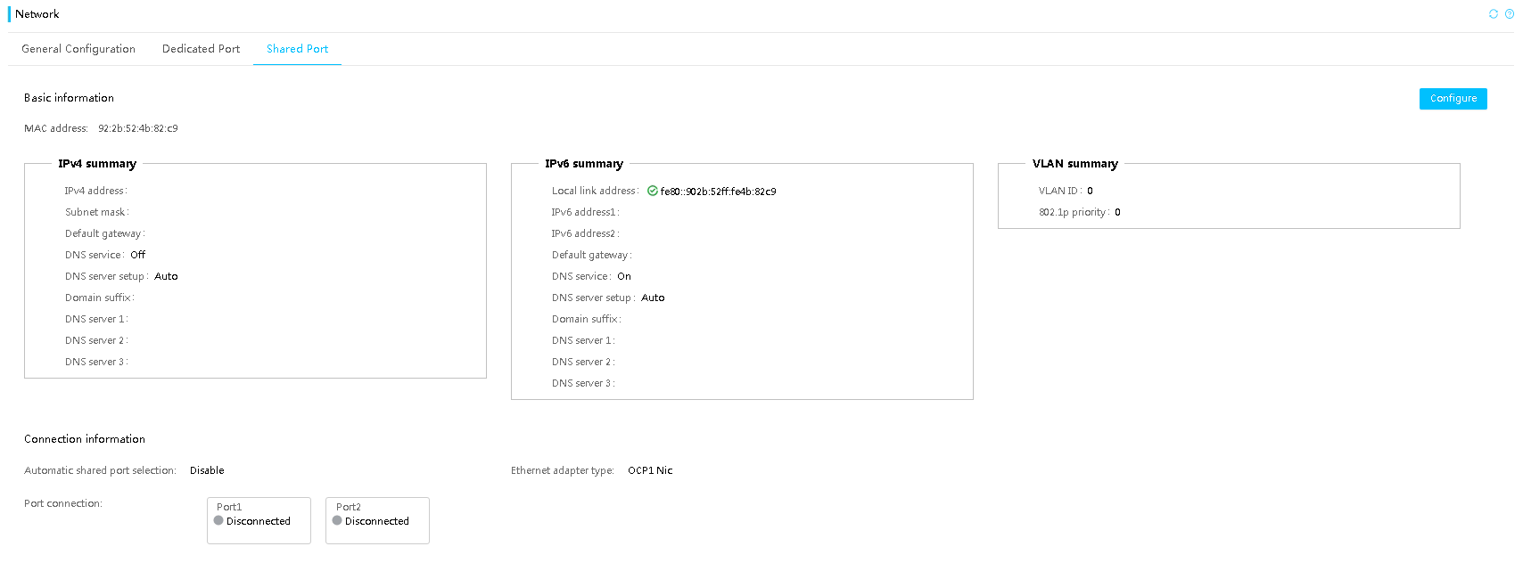
Configure self-negotiation settings
1. On the top navigation bar, click Configuration.
You are placed on the Network page.
2. On the Dedicated Port tab, click Configure.
3. In the Auto-negotiation section, perform the following tasks:
¡ If you enable self-negotiation settings, the dedicated port will negotiate with the switch to set the duplex mode and speed automatically. No manual configuration is required.
¡ If you disable self-negotiation settings, you are required to configure the duplex mode and speed manually.
4. Click Save.
Figure 46 Configuring self-negotiation settings

Parameters
· Port connection: Displays whether a cable is connected to the port. Options include:
¡ Disconnected—The port is disconnected.
¡ Active—The port is connected and is in active state.
· Domain suffix: Domain prefix registered in DNS server. This domain suffix will be automatically combined with the HDM host name to form a fully qualified domain name for HDM access.
· DNS server 1 to 3: Specifies DNS servers. You can specify a maximum of three DNS servers. The priorities of DNS servers 1, 2, and 3 are in descending order.
· Destination: Destination network address to which the packet will be sent.
· Mask: Subnet mask of the network address.
· Gateway: Address of the gateway connected to the interface of the adjacent router.
· Full-duplex: Data can be transmitted by using the dedicated network port in both directions at the same time.
· Half-duplex: Data can be transmitted by using the dedicated network port only in one direction at a time.
View shared network port information
Perform this task to view information about the shared network port, including MAC address, connection status, IPv4 and IPv6 addresses, and VLAN settings.
Procedure
1. On the top navigation bar, click Configuration.
You are placed on the Network page.
2. On the Shared Port tab, view information about the shared network port.
3. (Optional.) To view the state of an address, hover over the icon before the link local address or IPv6 address. Available states include Pending, Failed, and Active.
Figure 47 Viewing shared network port information

Parameters
· Connection Information: Displays connection information about shared network ports, including automatic shared port selection state, Ethernet adapter type, and whether a cable is connected to each port. This field is not available when no Ethernet adapter is installed or the installed Ethernet adapters do not support NCSI. Options include:
¡ Disconnected—The port is disconnected.
¡ Connected—The port is connected but is not in active state.
¡ Active—The port is connected and is in active state.
Configure the shared network port
Perform this task to configure information about the shared network port, including MAC address, connection status, IPv4 and IPv6 addresses, and VLAN settings.
Domain Name System (DNS) is a distributed database used by TCP/IP applications to translate domain names into IP addresses. You can configure DNS to enable access to HDM by using a domain name instead of the management IP address of HDM.
Restrictions and guidelines
See "General restrictions and guidelines for network configuration."
An IPv6 address assigned by the DHCP server or configured through stateless autoconfiguration supports only the 64-bit prefix.
If you cannot log in to HDM at its IPv6 address, disable proxy server in the browser and then try again.
If you are manually specifying IPv6 addresses of DNS servers, specify global IPv6 addresses.
If an invalid DNS server address is configured, the DNS registration might take a long time.
DNS is configurable only when the corresponding IPv4 or IPv6 network service is enabled.
The DNS configuration might change only when the following conditions are met:
· The obtaining method of an IPv4 or IPv6 address changes from DHCP server assignment to manual configuration.
· The Configure DNS service field is IPv4 (Auto)/ IPv6 (Auto).
In this case, the Configure DNS service field will switch to Manual automatically and the system will continue to use the domain suffix and DNS server information before the switch.
After disabling IPv6 configuration, you can still use the IPv6 link-local address.
Prerequisites
Verify that the dedicated network port is physically connected to the network.
Configure IPv4 settings
1. On the top navigation bar, click Configuration.
You are placed on the Network page.
2. Click the Shared Port tab.
3. Click Configure.
4. Select Enable for IPv4 to enable IPv4 network service.
5. Configure IPv4 address settings for the port:
¡ To use the IP address automatically assigned by a DHCP server, select Automatic IP obtaining. This is the default setting.
¡ To manually configure static IP address settings, clear Automatic IP obtaining, and then enter an IPv4 address, subnet mask, and default gateway address.
6. In the Configure DNS service area, select Enable for DNS service.
7. Select Manual, or Auto from the Configure DNS service field. To select Auto, you must enable Automatic IP Obtaining first.
¡ If you select Auto, the Domain suffix field will be automatically populated, and HDM will search for DNS servers automatically.
¡ If you select Manual, enter a domain suffix in the Domain suffix field, and enter the IP addresses of DNS servers. The DNS server information is optional. If you do not enter any information about DNS servers, the DNS configuration cannot take effect.
8. Configure the destination address, mask, and gateway in the Static route 1 configuration and Static route 2 configuration fields.
¡ The host number of the destination address must be all zero.
¡ The addresses cannot be on the same network segment as the IPv4 address used by the network interface, including static and dynamic addresses.
¡ Make sure any two routes are on different network segments.
9. Click Save.
Figure 48 Configuring IPv4 settings

Configure IPv6 settings
1. On the top navigation bar, click Configuration.
You are placed on the Network page.
2. Click the Shared Port tab.
3. Click Configure.
4. Select Enable for IPv6 to enable IPv6 network service.
5. Configure IPv6 address settings for the port:
¡ To use the IP address automatically assigned by a DHCP server, select Automatic IP obtaining.
¡ To manually configure static IP address settings, clear Automatic IP obtaining, and then enter an IPv6 address, the prefix length (in the range of 1 to 127), and default gateway address fe80::9628:2eff:fe9c:ffda.
6. In the Configure DNS service area, select Enable for DNS service.
7. Select Manual, or Auto from the Configure DNS service field. To select Auto, you must enable Automatic IP Obtaining first.
¡ If you select Auto, the Domain suffix field will be automatically populated, and HDM will search for DNS servers automatically.
¡ If you select Manual, enter a domain suffix in the Domain suffix field, and enter the IP addresses of DNS servers. The DNS server information is optional. If you do not enter any information about DNS servers, the DNS configuration cannot take effect.
8. Configure the destination address, prefix length, and gateway in the Static route 1 configuration and Static route 2 configuration fields.
¡ The host number of the destination address must be all zero.
¡ The value range of the prefix is 4 to 128.
¡ The addresses cannot be on the same network segment as the IPv6 address used by the network interface, including static and dynamic addresses.
¡ Make sure any two routes are on different network segments.
9. Click Save.
Figure 49 Configuring IPv6 settings

Configure VLAN settings
1. On the top navigation bar, click Configuration.
You are placed on the Network page.
2. Click the Shared Port tab.
3. Click Configure.
4. Select Enable for VLAN to enable VLAN service.
5. Enter a VLAN ID in the range of 2 to 4094.
6. Enter an 802.1p priority in the range of 0 to 7.
The 802.1p priority determines the transmission priority of the traffic from the VLAN when congestion occurs. The higher the value, the higher the priority.
7. Click Save.
Figure 50 Configuring VLAN settings
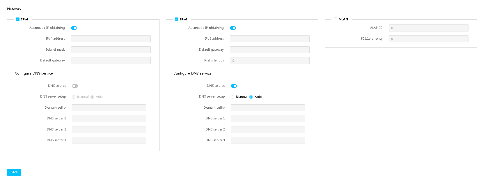
Parameters
· Domain suffix: Domain prefix registered in DNS server. This domain suffix will be automatically combined with the HDM host name to form a fully qualified domain name for HDM access.
· DNS server 1 to 3: Specifies DNS servers. You can specify a maximum of three DNS servers. The priorities of DNS servers 1, 2, and 3 are in descending order.
· Destination: Destination network address to which the packet will be sent.
· Mask: Subnet mask of the network address.
· Gateway: Address of the gateway connected to the interface of the adjacent router.
View port information in active/standby mode
With the active/standby mode enabled, you can perform this task to view the ports, including the MAC address, connection status, IPv4 and IPv6 addresses, and VLAN settings.
Procedure
1. On the top navigation bar, click Configuration.
You are placed on the Network page.
2. On the Active/Standby Mode Port tab, view the port information.
3. (Optional.) To view the state of an address, hover over the icon before the link local address or IPv6 address. Available states include Pending, Failed, and Active.
Figure 51 Viewing port information in active/standby mode
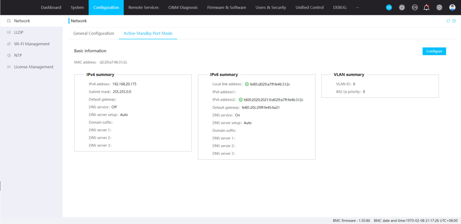
Parameters
· Connection Information: Displays connection information about shared network ports, including automatic shared port selection state, Ethernet adapter type, and whether a cable is connected to each port. This field is not available when no Ethernet adapter is installed or the installed Ethernet adapters do not support NCSI. Options include:
¡ Disconnected—The port is disconnected.
¡ Connected—The port is connected but is not in active state.
¡ Active—The port is connected and is in active state.
Configure the active/standby mode
With the active/standby mode enabled, you can perform this task to configure the ports, including the MAC address, connection status, IPv4 and IPv6 addresses, and VLAN settings.
Domain Name System (DNS) is a distributed database used by TCP/IP applications to translate domain names into IP addresses. You can configure DNS to enable access to HDM by using a domain name instead of the management IP address of HDM.
Restrictions and guidelines
DNS is configurable only when the corresponding IPv4 or IPv6 network service is enabled.
The DNS configuration might change only when the following conditions are met:
· The obtaining method of an IPv4 or IPv6 address changes from DHCP server assignment to manual configuration.
· The Configure DNS service field is IPv4 (Auto)/ IPv6 (Auto).
In this case, the Configure DNS service field will switch to Manual automatically and the system will continue to use the domain suffix and DNS server information before the switch.
If an invalid DNS server address is configured, the DNS registration might take a long time.
VLAN settings take effect only when the active/standby mode is enabled and the shared network port is used.
After disabling IPv6 configuration, you can still use the IPv6 link-local address.
Configure IPv4 settings
1. On the top navigation bar, click Configuration.
You are placed on the Network page.
2. Click the Active/Standby Mode tab.
3. Click Configure.
4. Select Enable for IPv4 to enable IPv4 network service.
5. Configure IPv4 address settings for the port:
¡ To use the IP address automatically assigned by a DHCP server, select Automatic IP obtaining. This is the default setting.
¡ To manually configure static IP address settings, clear Automatic IP obtaining, and then enter an IPv4 address, subnet mask, and default gateway address.
6. In the Configure DNS service area, select Enable for DNS service.
7. Select Manual, or IPv4 (Auto) from the Configure DNS service field. To select IPv4 (Auto), you must enable Automatic IP Obtaining first.
¡ If you select IPv4 (Auto), the Domain suffix field will be automatically populated, and HDM will search for DNS servers automatically.
¡ If you select Manual, enter a domain suffix in the Domain suffix field, and enter the IP addresses of DNS servers. The DNS server information is optional. If you do not enter any information about DNS servers, the DNS configuration cannot take effect.
8. Configure the destination address, mask, and gateway in the Static route 1 configuration and Static route 2 configuration fields.
¡ The host number of the destination address must be all zero.
¡ The addresses cannot be on the same network segment as the IPv4 address used by the network interface, including static and dynamic addresses.
¡ Make sure any two routes are on different network segments.
9. Click Save.
Figure 52 Configuring IPv4 settings

Configure IPv6 settings
1. On the top navigation bar, click Configuration.
You are placed on the Network page.
2. Click the Active/Standby Mode tab.
3. Click Configure.
4. Select Enable for IPv6 to enable IPv6 network service.
5. Configure IPv6 address settings for the port:
¡ To use the IP address automatically assigned by a DHCP server, select Automatic IP obtaining.
¡ To manually configure static IP address settings, clear Automatic IP obtaining, and then enter an IPv6 address, the prefix length (in the range of 1 to 127), and default gateway address fe80::9628:2eff:fe9c:ffda.
6. In the Configure DNS service area, select Enable for DNS service.
7. Select Manual, or IPv6 (Auto) from the Configure DNS service field. To select IPv6 (Auto), you must enable Automatic IP Obtaining first.
¡ If you select IPv6 (Auto), the Domain suffix field will be automatically populated, and HDM will search for DNS servers automatically.
¡ If you select Manual, enter a domain suffix in the Domain suffix field, and enter the IP addresses of DNS servers. The DNS information filed field is optional. If you do not enter any information about DNS servers, the DNS configuration cannot take effect.
8. Configure the destination address, prefix length, and gateway in the Static route 1 configuration and Static route 2 configuration fields.
¡ The host number of the destination address must be all zero.
¡ The value range of the prefix is 4 to 128.
¡ The addresses cannot be on the same network segment as the IPv6 address used by the network interface, including static and dynamic addresses.
¡ Make sure any two routes are on different network segments.
9. Click Save.
Figure 53 Configuring IPv6 settings
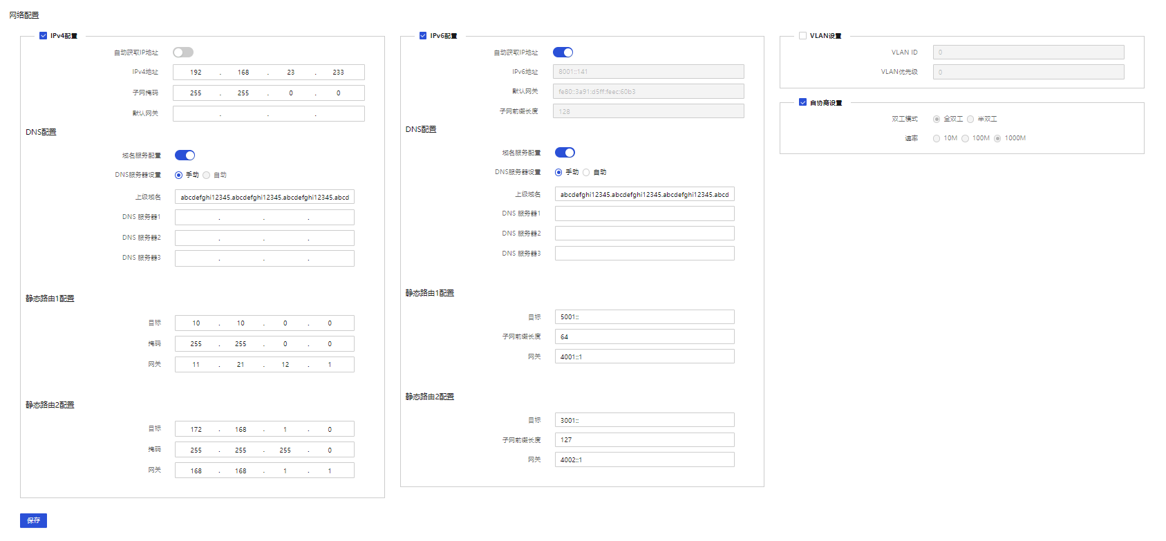
Configure VLAN settings
1. On the top navigation bar, click Configuration.
You are placed on the Network page.
2. Click the Active/Standby Mode tab.
3. Click Configure.
4. Select Enable for VLAN to enable VLAN service.
5. Enter a VLAN ID in the range of 2 to 4094.
6. Enter an 802.1p priority in the range of 0 to 7.
The 802.1p priority determines the transmission priority of the traffic from the VLAN when congestion occurs. The higher the value, the higher the priority.
7. Click Save.
Figure 54 Configuring VLAN settings
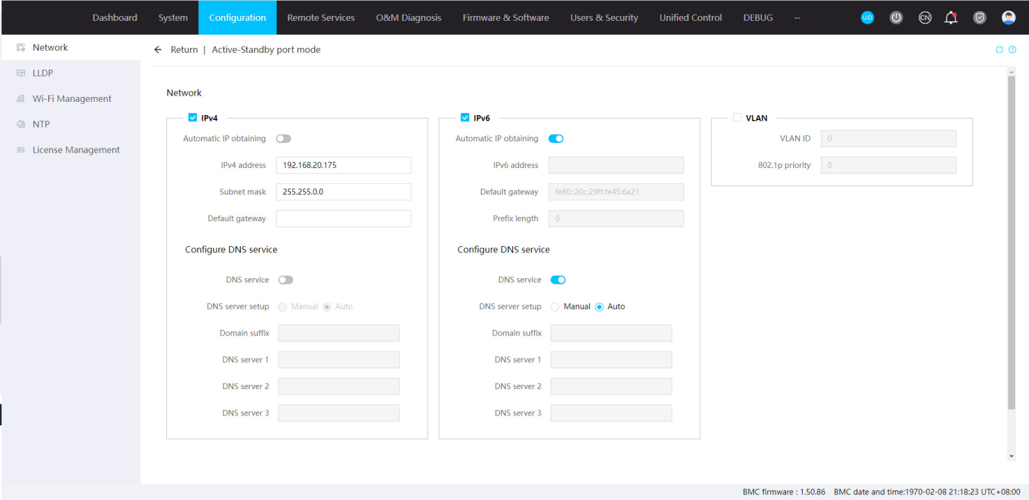
Parameters
· Domain suffix: Domain prefix registered in DNS server. This domain suffix will be automatically combined with the HDM host name to form a fully qualified domain name for HDM access.
· DNS server 1 to 3: Specifies DNS servers. You can specify a maximum of three DNS servers. The priorities of DNS servers 1, 2, and 3 are in descending order.
· Destination: Destination network address to which the packet will be sent.
· Mask: Subnet mask of the network address.
· Gateway: Address of the gateway connected to the interface of the adjacent router.
Configure LLDP
The Link Layer Discovery Protocol (LLDP) is a standard link layer protocol that allows network devices from different vendors to discover neighbors and exchange system and configuration information.
Perform this task to set the status and working mode of LLDP, and view related information about LLDP.
Procedure
1. On the top navigation bar, click Configuration.
2. In the left navigation pane, select LLDP.
3. Enable or disable LLDP as needed. By default, LLDP is diabled.
4. If you select to enable LLDP, select a working mode and the clike Save. By default, the working mode is TxRx.
5. View information about the received LLDP frames.
The list displays information about all connected devices of the server. If a device is unreachable or does not support displaying or sending LLDP frames, the corresponding fields display N/A.
Figure 55 Configuring LLDP
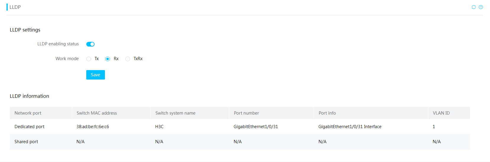
Parameters
· Working mode: Working mode of LLDP.
¡ Tx—Transmit mode. The device only sends but does not accept LLDP frames. This mode is suitable for scenarios that require information about the device itself, but do not require information about other devices.
¡ Rx—Receive mode. The device only accepts but does not send LLDP frames. This mode is suitable for scenarios that require other device information but do not require information about the device itself.
¡ TxRx—Transmit and receive mode. The device sends and receives LLDP frames. This mode is suitable for scenarios that require the exchange of device information.
· Network port: Network port of the server that receives LLDP frames.
· Switch MAC address: MAC address of the connected switch.
· Switch system name: System name of the connected switch.
· Port number: Number of the connected switch port.
· Port info: Information about the connected switch port, port name for example.
· VLAN ID: ID of the VLAN to which the server port belongs.
Configure Wi-Fi settings
Perform this task to configure Wi-Fi settings after you connect a USB Wi-Fi adapter to the server. This enables users to access the server through wireless connections and view information about online wireless clients.
Restrictions and guidelines
To restore the network shut down by idle timeout, you can reconnect the USB Wi-Fi adapter or log in to HDM to enable the network.
Procedure
1. On the top navigation bar, click Configuration.
2. In the left navigation pane, select Wi-Fi Management.
The page that opens displays current Wi-Fi settings and information about online wireless clients.
3. Configure Wi-Fi settings as needed:
¡ Enter the Wi-Fi name.
¡ Select the encryption method. If you select Encrypted, you must also specify a Wi-Fi password.
¡ Specify the idle timeout.
¡ Enter the IPv4 address of the wireless network.
¡ Specify the IPv4 address range for IP address assignment to clients.
4. Click Save.
Figure 56 Configuring Wi-Fi settings
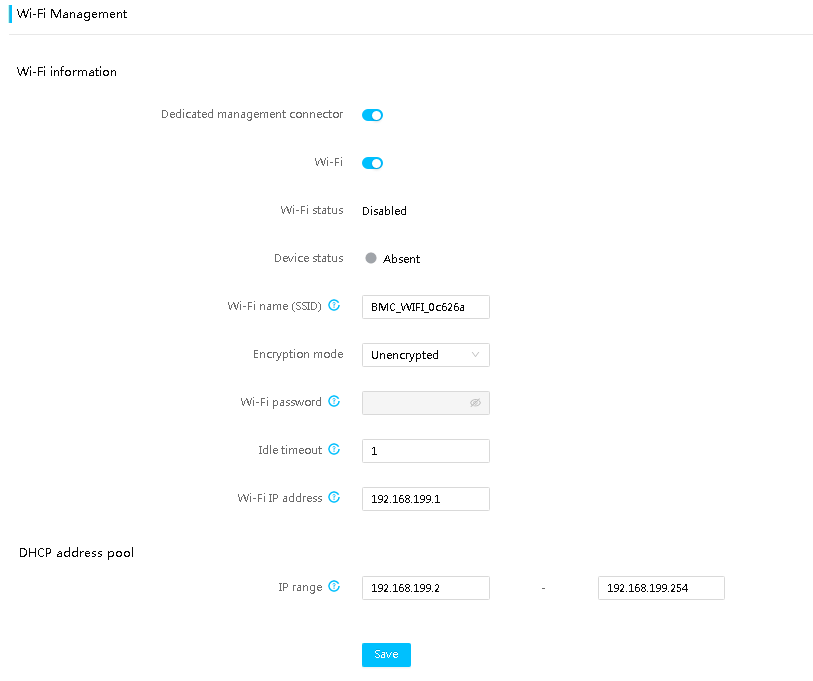
5. View client access information.
Figure 57 Viewing client access information
Parameters
· Device status: Presence status of the USB Wi-Fi adapter.
· Wi-Fi name: Name of the wireless network, a case-sensitive string of 1 to 31 characters. Only letters, digits, dots (.), hyphens (-), and underscores (_) are allowed. This field is required. By default, the name is in the HDM_WIFI_xxxxxx format, where xxxxxx represents the last 6 characters of the MAC address of the HDM dedicated management port.
· Encryption mode: Whether to enable network encryption. By default, the network is not encrypted.
· Wi-Fi password: Password of the wireless network, a case-sensitive string of 8 to 63 characters. Only letters, digits, spaces, and special characters `~!@#$%^&*()_+-=[]\{}|;':,./<>? are allowed. This field is required if the encryption mode is Encrypted.
· Idle timeout: Maximum idle period before the network is shut down, in the range of 0 to 200 hours. 0 indicates that wireless network will not be shut down. By default, the value is 1. A network is considered idle if no online clients exist.
· Wi-Fi IP address: IP address of the wireless network. By default, the IP address is 192.168.199.1. The subnet mask is fixed to 255.255.255.0. The IP address cannot belong to the same subnet as the IP address of the HDM dedicated or shared network port.
· IP range: IPv4 address range for IP address assignment to online clients. Make sure the IP address range is in the same subnet as the Wi-Fi IP address. The subnet mask is fixed to 255.255.255.0.
· No.: Number of an online client. The system allows a maximum of two clients to come online at the same time.
· Client MAC address: MAC address of an online client.
· Client IP address: IPv4 address of an online client.
· Host name: Host name of an online client.
NTP
Use this feature to obtain the correct system date and time from an NTP server.
You can manually specify one primary NTP server, one secondary NTP server, and one tertiary NTP server. When synchronizing time with NTP, HDM first uses the primary NTP server. If the primary NTP server is not available, HDM uses the secondary NTP server. If neither the primary nor secondary server is available, HDM uses the tertiary NTP server.
With HDM, you can also choose to obtain NTP server settings from the DHCP server when all manually specified NTP servers are unavailable. If the DHCP server is not available, HDM uses the system date and time obtained in the most recent successful NTP time synchronization or uses the local system date and time.
Configure NTP settings
Restrictions and guidelines
If time synchronization with the NTP server fails because the NTP server is not reachable, the Web interface displays an error message about the failure to obtain date and time from the NTP server. To synchronize with the NTP server after it becomes reachable or to start new time synchronization, you must click Save again. HDM does not perform time synchronization without being triggered by the Save action.
If the Windows built-in NTP server is used for time synchronization, you need to set LocalClockDispersion to 0 in the HKEY_LOCAL_MACHINE\SYSTEM\CurrentControlSet\Services\W32Time\Config path in the Windows registry.
Procedure
1. On the top navigation bar, click Configuration.
2. In the left navigation pane, select NTP.
3. In the work pane, select the time zone of the server.
4. Select Enable or Disable for Time auto sync.
¡ With this feature enabled, HDM synchronizes time settings with a manually specified NTP server. If the manually specified NTP servers fail, HDM synchronizes settings with the NTP server obtained from the DHCP server. This is the default setting.
¡ With this feature disabled, HDM synchronizes time settings with ME. After the BIOS reboots, HDM starts to synchronize time settings based on the time in the BIOS (UTC time) and the specified time zone. For example, if the specified time zone is UTC+8, HDM uses a time eight hours earlier than the time in the BIOS. For example, if the BIOS time is 8 o'clock, the HDM time is 16 o'clock.
5. If you select Enable for Time auto sync, set the NTP synchronization interval, and enter the addresses of the primary, secondary, and tertiary NTP servers.
The server addresses can be IPv4 addresses, IPv6 addresses, or domain names, but cannot be IPv6 local link addresses or IPv6 multicast addresses. The secondary and tertiary servers are optional. The HDM server uses the secondary NTP server only when the primary NTP server fails, and uses the tertiary NTP server only when both the primary and secondary NTP servers fail.
By default, the primary NTP server address is 1.cn.pool.ntp.org, the secondary NTP server address is 2.cn.pool.ntp.org, and the tertiary server address is not specified.
6. Click Save.
HDM attempts to synchronize time.
Figure 58 Configuring NTP
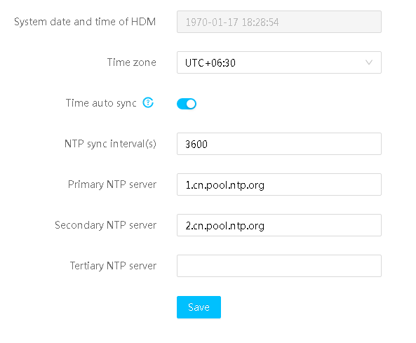
Parameters
NTP sync interval: Set the interval at which HDM synchronizes time from the NTP server. By default, the interval is 3600 seconds. The value range is 600 to 2592000 seconds. This setting takes effect only when NTP is configured.
License management
To use license-based features, you must purchase licenses from server manufacturers and install the licenses. For more information about license-based features of HDM, see the HDM license matrixes for HDM. For more information about obtaining licenses, see the license user guide.
After obtaining an activation file, you can use this feature to install the activation file and then use the license-based features.
Restrictions and guidelines
· Before installing the activation file of a formal license, make sure the server DID is the same as the DID used to apply for the activation file and the license state for the server meets any one of the following conditions:
¡ The server is not installed with any activation file of a formal license or trial license.
¡ The activation files of other licenses are uninstalled and the corresponding uninstall files are exported.
¡ The activation file of the current trial license is expired.
¡ The activation file of the trial license is uninstalled.
· Before installing the activation file of a trial license, make sure the server DID is the same as the DID used to apply for the activation file and the activation file is still valid.
· Only administrator role users and custom users that have the configuration privileges can use the license management feature.
Procedure
1. On the top navigation bar, click Configuration.
2. In the left navigation pane, select License Management.
Figure 59 License management page
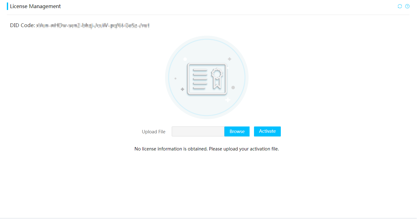
3. Click Browse. On the page that opens, select an activation file.
4. Click Activate to install the activation file.
5. After installation, perform the following tasks as needed:
¡ View the serial number, type, state, and validity period for the license.
¡ To
export the activation file for
backup purpose, click the icon ![]() in the Licensing State field.
in the Licensing State field.
¡ To uninstall the activation file, click License Management and select Uninstall. On the page that opens, enter the user login password and click OK. HDM will uninstall the activation file once the password verification succeeds.
¡ After uninstalling the activation file, to export the corresponding uninstall file, click Export Uninstall File.
Figure 60 License installed
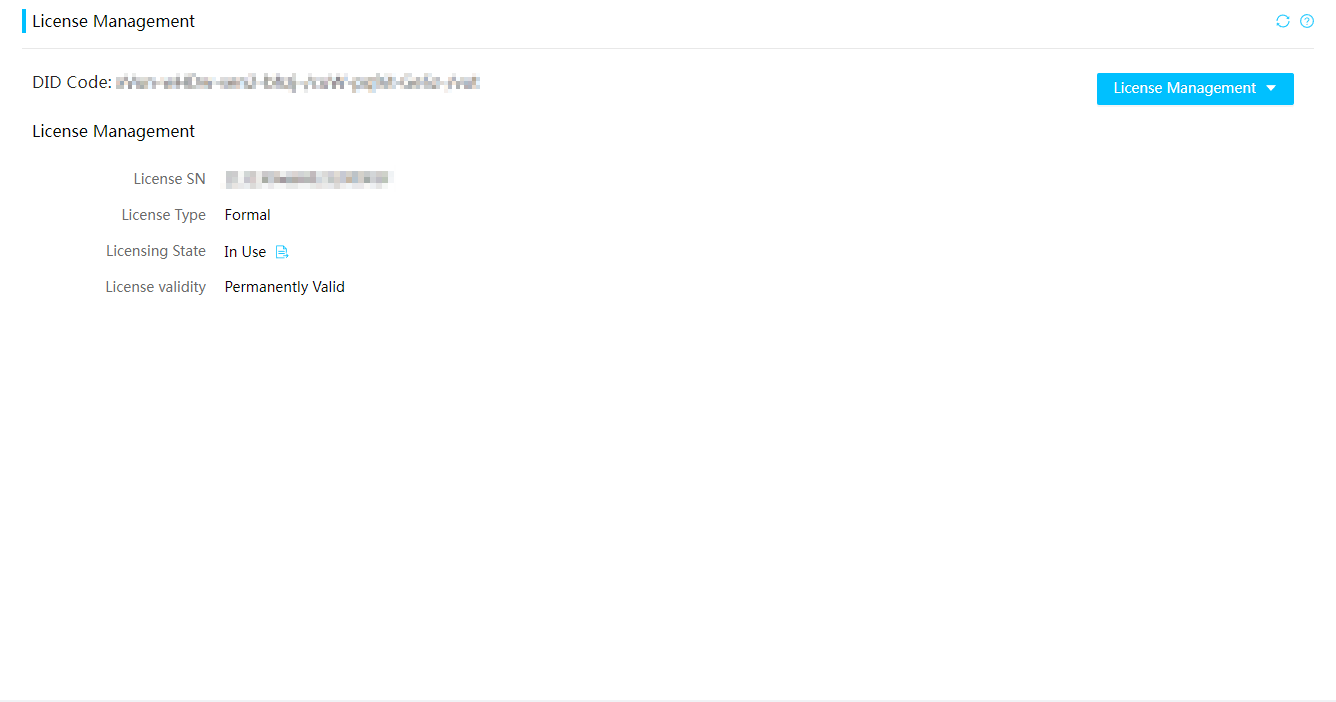
Parameters
· DID Code: Device identification code.
· License SN: Serial number of the license.
· License Type:
¡ Formal: A formal license can be installed, uninstalled, and transferred and is valid permanently.
¡ Trial: A trial license can be installed, uninstalled, cannot be transferred, and is valid for 90 days. When a trial license expires, the license-based feature becomes unavailable. To continue to use the feature, you must purchase and install a formal license for it.
· License State: Status of the license. Options include In Use, Expired Soon, Expired, Uninstalled, and Unavailable. When the license status becomes unavailable, contact Technical Support.
· License Validity: Valid duration for the activation file.
Remote services
Access services
View services and user sessions
Restrictions and guidelines
The available services vary by server model.
Procedure
1. In the navigation pane, select Remote Services > Services.
The service list page opens.
2. In the work pane, click View for an access service to view its detailed information, as shown in Figure 61.
Figure 61 Viewing access service entries
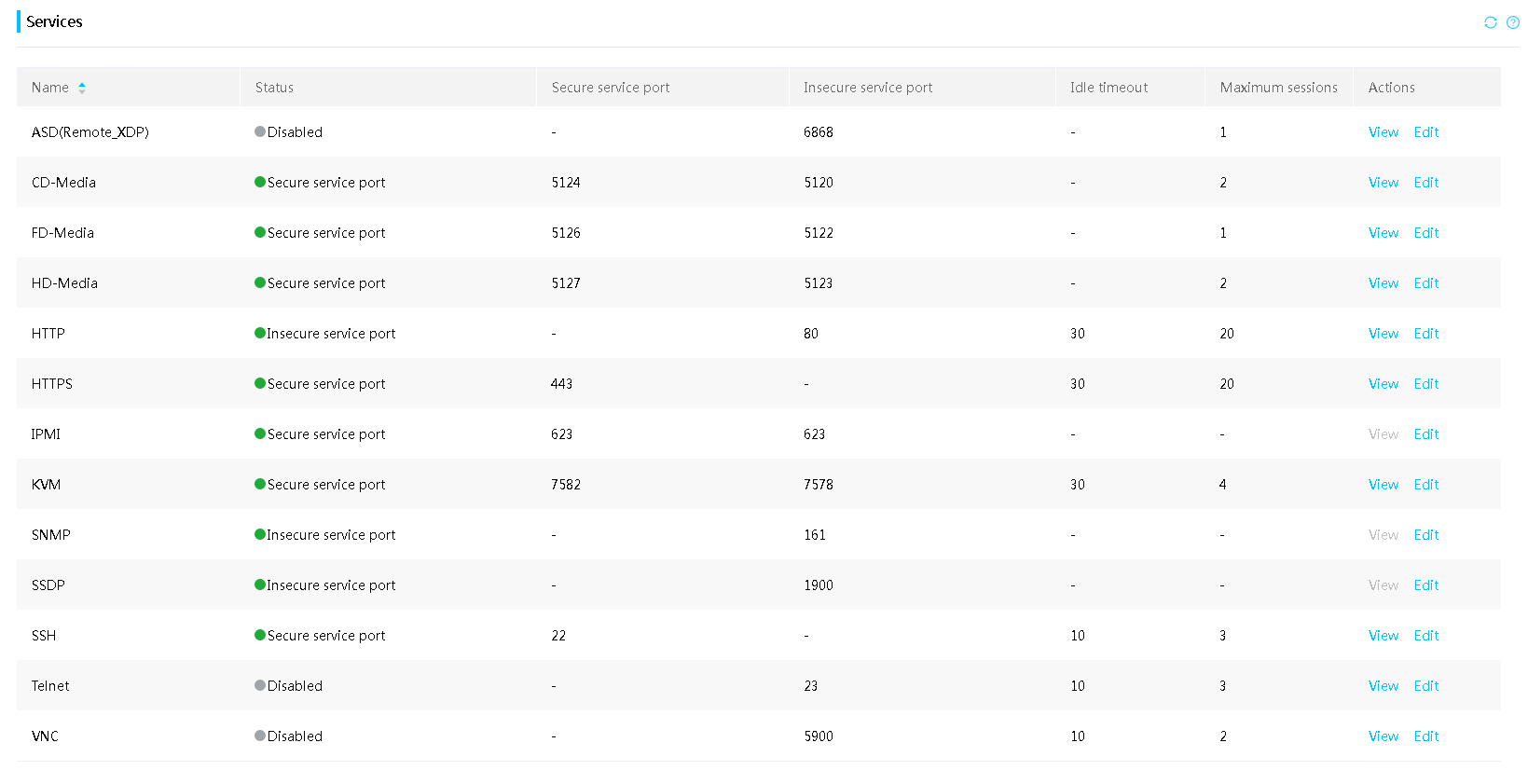
3. In the session list that opens, perform either of the following tasks, as shown in Figure 62:
¡ To close a session, click Delete for the session.
¡ To return to the previous page, click Close.
Figure 62 Viewing access services
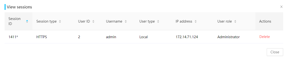
Parameters
· Name: Name of the service.
HDM provides the following services:
¡ CD-Media—Access to the virtual CDs and DVDs.
¡ FD-Media—Access to the virtual floppy disk drives.
¡ HD-Media—Access to the virtual disk drives and USB.
¡ HTTP—Connect to HDM by using Hyper Text Transfer Protocol (HTTP).
¡ HTTPS—Connect to HDM by using Hyper Text Transfer Protocol over SecureSocket Layer (HTTPS).
¡ IPMI—Remote Management Control Protocol (RMCP) or RMCP+ connections to HDM.
¡ KVM—Access to the server from a remote console.
¡ ASD (Remote_XDP)—Remote debugging and diagnosis through XDP. This service is available only for the R4700 G6, R4900 G6, and B5700 G6 servers.
¡ SNMP—SNMP access to HDM.
¡ SSDP—SSDP access to HDM.
¡ SSH—SSH access to HDM.
¡ Telnet—Telnet access to HDM.
¡ VNC—Access to the server from a Virtual Network Computing (VNC) client.
· Status: Status of the service. Options include:
¡ Disabled.
¡ Enabled.
· Insecure service port: Port used for unencrypted communication of the service.
· Secure service port: Port used for encrypted communication of the service.
· Idle timeout: Idle timeout time of the user session, in minutes. A user session automatically disconnects when it times out.
· Maximum sessions: Maximum number of sessions supported for the service. The maximum number of sessions supported for HTTP or HTTPS is not fixed, but the total maximum number of the two types of sessions is 20.
· Session ID: ID that identifies the session among HDM user sessions. An asterisk (*) mark indicates that the session was established by using the IP address with which the client accesses the current Web interface.
· Session type: Protocol type or service type of the session.
· User ID: ID of the user account in the user list on the Users & Security > Users page. 0 indicates that the user is neither a local user nor a domain user.
· Username: Username of the user account.
· User type: Type of the user account.
· IP address: IP address of the user using the service.
· User role: User role of the user account, which represents a set of access privileges.
Edit an access service
Restrictions and guidelines
The available services vary by server model.
If you change the default secure or insecure service port of a service, follow these guidelines when you use that service:
· If you change the default IPMI insecure service port number (623), you must use the -p parameter to explicitly specify the port number when you execute an IPMI command.
· If you change the default secure or insure HTTP or HTTPS service port number, you must explicitly specify the Web service port when you access HDM from a Web browser. The HDM URL address format is https://ip_address:secure-port.
· You can disable the insecure HTTP service port for users to access HDM only from the secure HTTP service port but you cannot disable the insecure HTTPS service port. When the insecure HTTP service port is disabled, you cannot access H5 KVM in unencrypted mode.
· If you change the default ASD(Remote_XDP) service port number (6868), you must also update the port number change to the OpenIPC client.
· Changing the settings of a service restarts the service. During the restart, the service is unavailable.
Procedure
1. In the navigation pane, select Remote Services > Services.
2. In the work pane, click Edit for the target service.
3. Edit service parameters, as shown in Figure 63.
Figure 63 Editing an access service
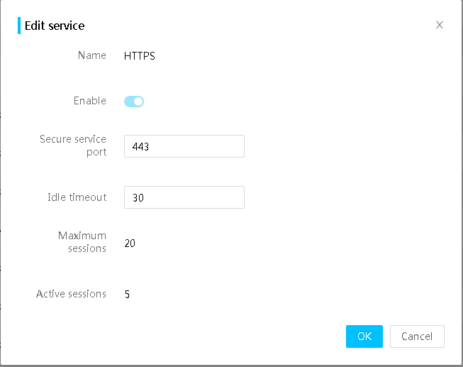
4. Edit the service status, port number, and idle timeout as needed.
5. Click OK.
Parameters
· Insecure service port: Set the service port number for unencrypted communication of the service. For access services except VNC, the value range is 1 to 65535. For VNC, the value range is 100 to 65535.
· Secure service port: Set the service port number for encrypted communication of the service. The value range is 1 to 65535.
Table 10 Default port numbers used by the supported access services
|
Service |
Default insecure port |
Default secure port |
|
CD-Media |
5120 |
5124 |
|
FD-Media |
5122 |
5126 |
|
HD-Media |
5123 |
5127 |
|
HTTP |
80 |
N/A |
|
HTTPS |
N/A |
443 |
|
IPMI |
623 |
623 |
|
KVM |
7578 |
7582 |
|
ASD(Remote_XDP) |
6868 |
N/A |
|
SNMP |
161 |
N/A |
|
SSDP |
1900 (fixed and unchangeable) |
N/A |
|
SSH |
N/A |
22 |
|
Telnet |
23 |
N/A |
|
VNC |
5900 |
N/A |
· Idle timeout: Set the session idle timeout time for the service. You can set the timeout for Web, HTTP, HTTPS, KVM, SSH, Telnet, and VNC services. The SSH and Telnet services use the same idle timeout time. If you set an idle timeout for both SSH and Telnet, the most recent configuration takes effect. The HTTP and HTTPS services use the same idle timeout time. If you modify one of the two idle timeout time, the other one will update automatically and accordingly.
Table 11 Timeout value ranges and default timeout settings of services
|
Service name |
Timeout value range (in minutes) |
Default timeout (in minutes) |
|
HTTP |
5 to 120 |
30 |
|
HTTPS |
5 to 120 |
30 |
|
KVM |
5 to 30 |
30 |
|
SSH |
1 to 30 |
10 |
|
Telnet |
1 to 30 |
10 |
|
VNC |
5 to 30 |
10 |
Remote console
You can manage the server and install an operating system (OS) from a remote console.
HDM supports a maximum of four remote control sessions. If you establish the first session, you are the primary user. All subsequent remote console users are secondary users and must obtain access permissions from the primary user.
HDM supports KVM, H5 KVM, and VNC remote consoles. This section describes how to use KVM and H5 KVM remote consoles and configure the VNC login password.
Restrictions and guidelines
To use KVM, contact Technical Support to obtain the user guide for KVM environment configuration.
To use KVM, you must first set up the OS environment. The environment setup configuration varies by OS type.
To use the VNC remote console, you must first install the VNC client. H5 KVM requires no client.
If you use the virtual media function to install an OS through a remote console, do not restart HDM, update HDM, or perform any power actions during the process.
Launch a KVM or H5 KVM remote console
Restrictions and guidelines
Do not use KVM and H5 KVM at the same time or start the remote console in multiple browsers on one PC.
For security purposes, grant full permission to a trustworthy secondary user when you close the remote console session as the primary user.
Granting full permission to a secondary user removes the full permission from the primary user. Then, the primary user has only the read-only permission.
The primary user can grant full permission to any secondary user when closing the KVM window. If the primary user does not grant full permission in 10 seconds, the permissions of secondary users remain unchanged.
The UID LED of the server flashes if a remote console is active.
Prerequisites
Before you can launch a remote control console, you must perform the following tasks:
· Make sure your user account has the remote control privilege. If you do not have the remote control privilege, contact the administrator.
· To launch the KVM console, make sure your user account has the KVM extended privilege. To launch the H5 KVM console, make sure your account has the KVM, HTTP, or HTTPS extended privileges. If you do not have the Web or KVM privilege, contact the administrator.
Procedure
1. In the navigation pane, select Remote Services > Remote Console, as shown in Figure 64.
Figure 64 Entering remote console page
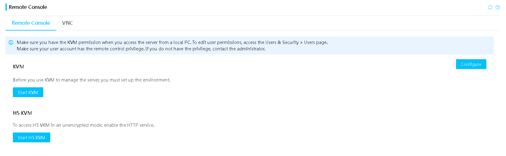
2. (Optional.) Click Configure, select a launch mode for KVM and H5 KVM, and then click OK.
3. Launch a remote console:
¡ To launch the KVM remote console, click Start KVM.
If no launch mode is specified for KVM, KVM will be launched in shared mode.
- If a secure port is specified for KVM, KVM supports the encrypted shared mode for data transmission.
- If an insecure port is specified for KVM, KVM supports the unencrypted shared mode for data transmission.
¡ To launch the H5 KVM remote console, click Start H5 KVM.
If no launch mode is specified for H5 KVM, H5 KVM will be launched shared mode.
- If an insecure port is specified for KVM and HTTP service is enabled, H5 KVM supports the unencrypted shared mode.
- If a secure port is specified for KVM and HTTPS service is enabled, H5 KVM supports the encrypted shared mode.
- If an insecure port is specified for KVM and HTTP service is disabled, you cannot start H5 KVM.
Encrypted modes transmit encrypted data and provide better security performance. Unencrypted modes transmit unencrypted data and provide higher transmission speed.
The remote console sign-in page opens.
Figure 65 Remote console sign-in page
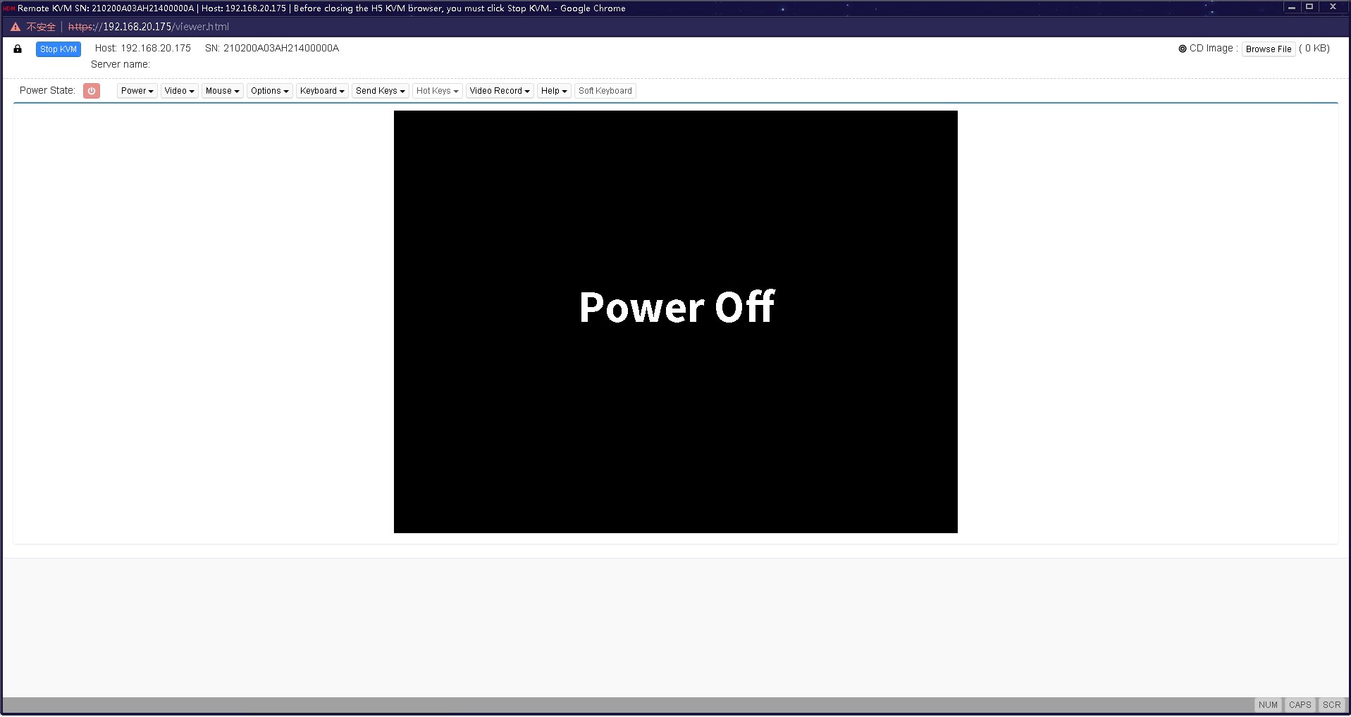
4. For a shared mode, wait for the access authorization from the primary user if you are not the first access user, as shown in Figure 66.
Figure 66 Waiting for remote console access authorization
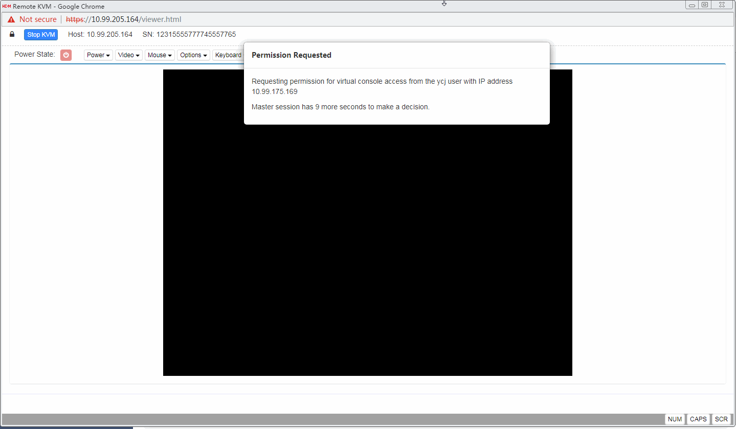
If you are the primary user, you might need to grant access permissions to other users, as shown in Figure 67.
Figure 67 Authorizing remote console access
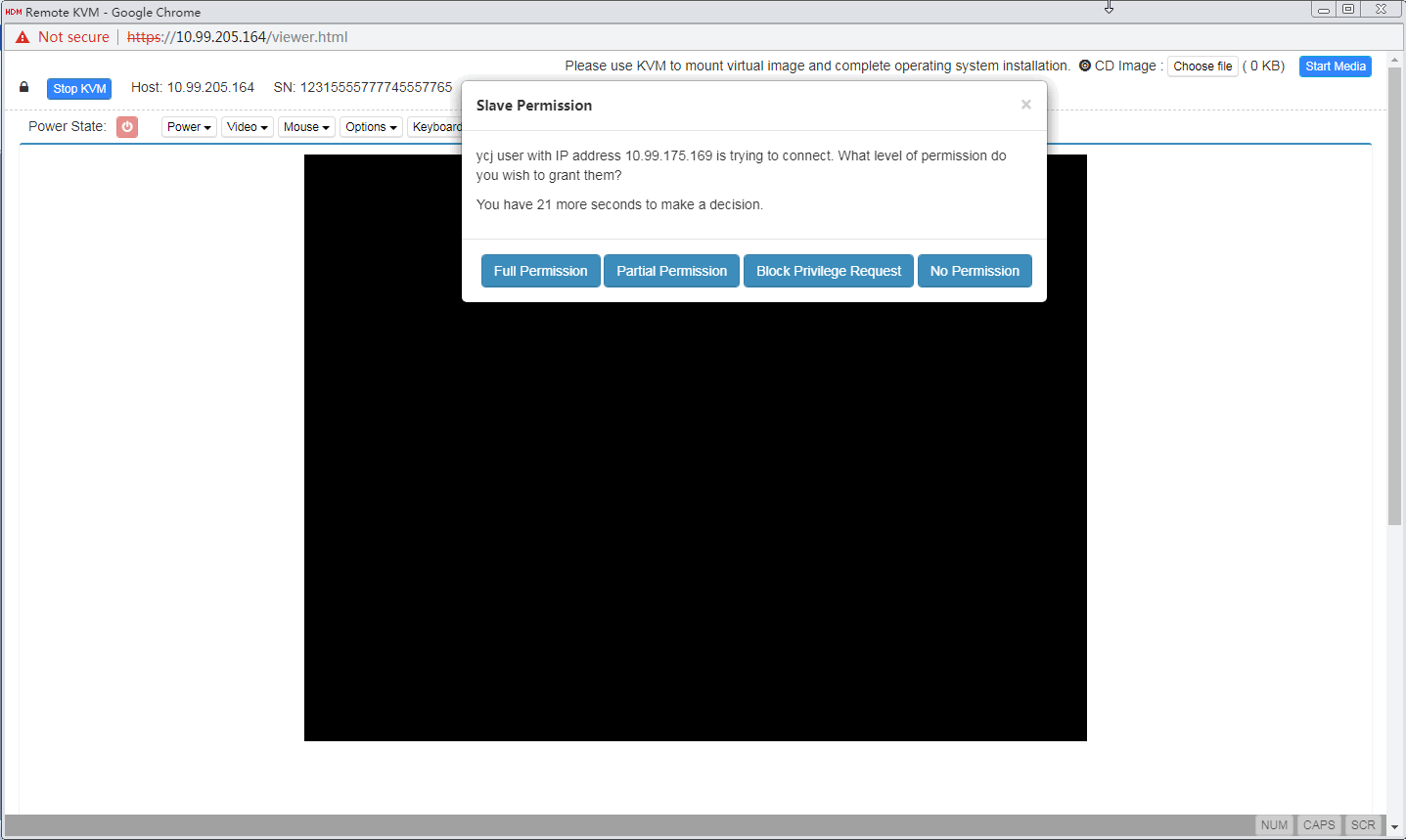
Parameters
· Dedicated mode: Includes Encrypted dedicated mode and Unencrypted dedicated mode. A dedicated mode allows for only one remote console session and grants the user with the full access permission. You can launch the remote console successfully in dedicated mode only if no other user is using the remote console.
· Shared mode: Includes Encrypted shared mode and Unencrypted shared mode. A shared mode allows for a primary session and multiple secondary sessions. If you are the first access user, the system assigns you with the full access permission. If you are a secondary user, the granted permission is decided by the primary user as follows:
¡ If you are granted full access permission, you can display information and configure the server.
¡ If you are granted read-only permission, you can only view videos and screenshots, and record videos. You cannot perform any configuration tasks.
¡ If your access is denied, the KVM window closes.
¡ If the primary user does not respond in 30 seconds, you are granted read-only permission.
Operate the server from KVM
Prerequisites
Launch a KVM remote console.
Block full permission requests
If you are the primary user (the user that established the first console session), you might receive full permission requests from remote console users who have only read-permission.
To block full permission requests, select Options > Block Privilege Request from the top menu bar.
Configure boot options for the next boot
To configure the boot option and boot mode for the server to use at the next reboot, select Options > Configure Boot Options from the top menu bar.
You can set the validity for the configuration to one-time or permanent.
· If the system boot order configured in permanent system boot options is inconsistent with the system boot order, the server will start based on the permanent settings.
· If the system boot order configured in one-time system boot options is inconsistent with the system boot order, the server will follow the one-time settings at next startup. The configured system boot options take effect after startup.
· If you configure boot options at the BIOS startup, the configuration might fail to take effect.
Access the server
You can use the keyboard, mouse, and monitor of the local PC to access the server.
Start up or shut down the server
|
|
WARNING! The Force Power-Off and Graceful Power-Off options only put the server in standby mode by removing power from most circuits. To maintain the server with all power removed, you must remove all power cords from the server. |
1. Select the Power menu from the top menu bar.
2. Select a menu option as needed.
|
Power menu option |
Purpose |
|
Force System Reset |
Warm reboots the server without power cycling the server. |
|
Force Power-Off |
Shuts down the server immediately by force. This action is equivalent to pressing the power button on the server for five seconds to put the server in standby mode. |
|
Graceful Power-Off |
Shuts down the operating system first, and then removes power from the server to put it in standby mode. |
|
Power On |
Starts up the server. |
|
Force Power-Cycle |
Powers off and then powers on the server. |
3. Use the power icon in the lower right corner of the console to verify the power state of the server.
¡ If
the server is up, the icon is in green (![]() ).
).
¡ If
the server is down, the icon is in red (![]() ).
).
Capture the screen
1. Select Options > Capture Screen from the top menu bar.
2. In the dialog box that opens, select the screenshot file storage path, enter the file name, and then click Save, as shown in Figure 68.
Figure 68 Capturing the screen
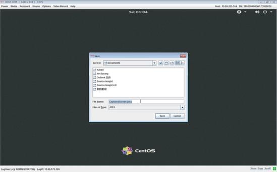
Record a video
1. Select Video Record > Settings from the top menu bar.
2. Set the video recording parameters, as shown in Figure 69:
¡ Video Length.
¡ Video to be Saved.
¡ Normalized video resolution to 1024 × 768.
Figure 69 Setting video recording parameters
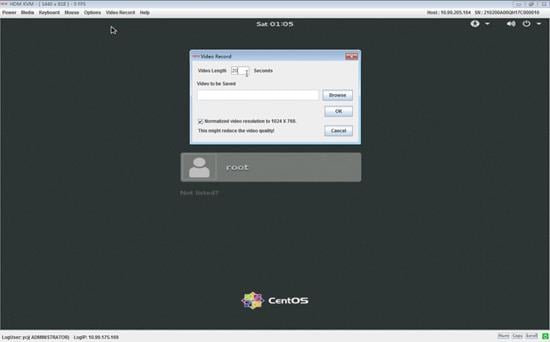
3. Select Video Record > Start Record to start video recording.
4. Select Video Record > Stop Record to stop video recording.
Mount virtual storage media
1. Select Media > Virtual Media Wizard from the top menu bar.
2. Mount a virtual storage medium, as shown in Figure 70:
¡ To mount a virtual CD/DVD, click the CD/DVD tab, click Browse next to a CD Image field to select a CD/DVD file or CD/DVD drive of the local PC, and then click Connect. Make sure the total length of the mounting path name and image name (including backslashes) does not exceed 255 characters.
¡ To mount a virtual floppy disk, click the Floppy tab, click Browse next to the Floppy Image field, select a floppy disk file from the local PC, and then click Connect. Make sure the total length of the mounting path name and image name (including backslashes) does not exceed 255 characters.
¡ To mount a virtual hard disk drive or USB, click the Hard disk/USB tab, and perform one of the following tasks:
- If the image already exists in the hard drive or USB, select HD/USB Image, click Browse next to the HD/USB Image field, select a disk file or USB device of the local PC, and then click Connect. Make sure the total length of the mounting path name and image name (including backslashes) does not exceed 255 characters.
- If the image does not exist in the hard drive or USB but the files to be mounted exist in the local PC, select Folder Path, click Browse next to the Folder Path field to select the folder from the local PC. Make sure that the length of the image name or the driver source (backslashes (\) included) does not exceed 255 characters. Then, click Browse next to the Image Path field to select a path from the hard drive or USB for saving the image generated by using the selected folder, and then click Connect.
Make sure the folder is not larger than 600 M, and the path for saving the image is different from the path for saving the folder.
Figure 70 Mounting a virtual storage medium
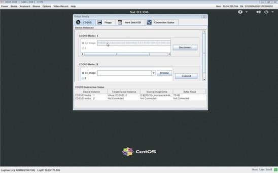
3. To unmount a virtual storage medium, access the medium tab, and click Disconnect.
Quit the remote console
To quit the remote console and disconnect
from HDM, click the close button ![]() of the
remote console window.
of the
remote console window.
The KVM idle timeout does not take effect if a virtual medium is mounted through the remote console.
Configure the peripherals in the KVM console
· To configure keyboard settings, select the Keyboard menu from the top menu bar, and then select the desired menu option.
|
Keyboard menu option |
Task |
|
Ctrl+Alt+Del |
Perform an action equivalent to pressing the Ctrl, Alt, and Delete keys simultaneously on the keyboard. |
|
Hot Keys |
Define and use hot keys. You can define a maximum of 20 hot keys, each being a combination of up to six keys. |
|
SoftKeyboard |
Open the soft keyboard. Only American English soft keyboard is supported. |
· To configure the mouse settings, select the Mouse menu from the top menu bar, and then select the desired menu option.
|
Mouse menu option |
Task |
|
Show Cursor |
· Select this option to display mouse pointer trails. · Clear this option to hide mouse pointer trails. |
|
Mouse Calibration |
Calibrates the mouse location in relative mouse mode. |
|
Mouse Mode |
The mouse mode is used to calculate the current location of the mouse. Options include: · Absolute mouse mode—Calculates the mouse location according to the screen's absolute coordinates. · Relative mouse mode—Calculates the mouse location according to the offset of the mouse movement. · Other mouse mode—Calculates the mouse location according to the distance from the mouse to the screen center. Mouse mode recommendations for server operating systems: · Use absolute mouse mode in Windows 2008, Windows 2012, Redhat 6.5, Redhat 7.0, CentOS 6.5, CentOS 7.1, Ubuntu 12.04, Ubuntu 15.04, SLES 11, and SLES 13. · Use relative mouse mode for versions lower than Redhat 6, CentOS 6, or Fedora 14. · Use other mouse mode in SLES 11 installation interface. · Use absolute mouse mode in any operating systems that are not mentioned above.
· As a best practice, do not change the mouse mode frequently. · The Show Cursor feature will be enabled automatically if you change the mouse mode from relative or other to absolute. |
Change the language in the KVM console
1. Select Options > GUI Languages from the top menu bar.
2. Change the language to Chinese or English.
Block full permission requests
If you are the primary user (the user that established the first console session), you might receive full permission requests from remote console users who have only read-permission.
To block full permission requests, select Options > Block Privilege Request from the top menu bar.
Configure boot options for the next boot
To configure the boot option, boot mode, and boot order for the server to use at the next reboot, select Options > Boot Options from the top menu bar.
Obtain version and copyright information
To obtain version and copyright right information, select Help > About HDM KVM from the top menu bar.
Operate the server from H5 KVM
Prerequisites
1. Launch an H5 KVM remote console.
2. To perform any server tasks except viewing videos and screenshots and recording videos, make sure you have full permission.
Block full permission requests
If you are the primary user (the user that established the first console session), you might receive full permission requests from remote console users who have only read-permission.
To block full permission requests, select Options > Block Privilege Request from the top menu bar.
Configure boot options for the next boot
To configure the boot option and boot mode for the server to use at the next reboot, select Options > Boot Options from the top menu bar.
You can set the validity for the configuration to one-time or permanent.
· If the system boot order configured in permanent system boot options is inconsistent with the system boot order, the server will start based on the permanent settings.
· If the system boot order configured in one-time system boot options is inconsistent with the system boot order, the server will follow the one-time settings at next startup. The configured system boot options take effect after startup.
· If you configure boot options at the BIOS startup, the configuration might fail to take effect.
Configure the system boot order
To configure the system boot order, select Options > Configure Boot Order from the top menu bar. This feature is available only for some servers.
The system boot order is effective as long as you do not change it.
If you configure this feature when BIOS is starting up, this feature will not take effect. Do not configure this feature at BIOS start up.
Access the server
You can use the keyboard, mouse, and monitor of the local PC to access the server.
Start up or shut down the server
|
|
WARNING! The Force Power Off and Graceful Power Off options only put the server in standby mode by removing power from most circuits. To maintain the server with all power removed, you must remove all power cords from the server. |
1. Select the Power menu from the top menu bar.
2. Select a menu option as needed.
|
Power menu option |
Purpose |
|
Immediate Reset |
Warm reboots the server without power cycling the server. |
|
Force Power Off |
Shuts down the server immediately by force. This action is equivalent to pressing the power button on the server for five seconds to put the server in standby mode. |
|
Graceful Power Off |
Shuts down the operating system first, and then removes power from the server to put it in standby mode. |
|
Power On |
Starts up the server. |
|
Power Cycle |
Powers off and then powers on the server. |
3. Use the power icon in the upper left corner of the console to verify the power state of the server.
¡ If
the server is up, the icon is in green (![]() ).
).
¡ If
the server is down, the icon is in red (![]() ).
).
Record a video
1. Select Video Record > Record Settings from the top menu bar.
Figure 71 Selecting record settings

2. Set the video recording parameters:
¡ Video Length—Enters the maximum time length of the video. The value range is 1 to 1800 seconds.
¡ Video Compression—Sets the view compression ratio. The value range is 0.1 to 1.
¡ Normalized video resolution to 1024 × 768—To use the 1024 × 768 resolution, select this option. If you do not select this resolution, the screen resolution of the server monitor is used.
Figure 72 Setting video recording parameters
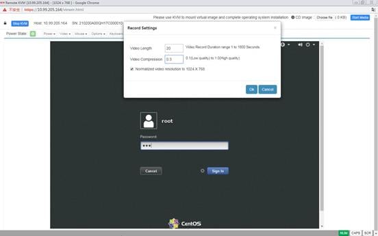
3. Select Video Record > Record Video to start video recording.
4. Select Video Record > Stop Record to stop video recording.
Play a video
1. Select the Video menu from the top menu bar.
2. Select a menu option as needed:
¡ To pause the video while it is playing, select Pause Video.
¡ To resume video playing, select Resume Redirection.
¡ To refresh the video displayed on the remote console, select Refresh Video.
Capture the screen
Select Video > Capture Screen from the top menu bar, as shown in Figure 73.
Figure 73 Capturing the screen
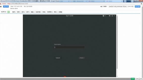
Open the soft keyboard
Select the SoftKeyboard menu from the top menu bar. Only American English soft keyboard is supported.
Quit the remote console
To quit the remote console and disconnect from HDM, click Stop KVM on the upper left corner of the remote console window.
The KVM idle timeout does not take effect if a virtual medium is mounted through the remote console.
Configure the peripherals in the H5 KVM console
· To configure keyboard settings, select the Keyboard menu from the top menu bar, and then select the desired menu option.
|
Keyboard menu option |
Task |
|
Keyboard Layout |
Change the keyboard layout. |
|
English U.S |
Use the U.S. English keyboard layout. |
· To perform Send Keys operations, select the Send Keys menu from the top menu bar, and then select the desired menu option.
|
Send Keys menu option |
Description |
|
Hold Down section |
|
|
Right Ctrl Key |
Perform an action equivalent to pressing the right Ctrl key on the keyboard. |
|
Right Alt Key |
Perform an action equivalent to pressing the right Alt key on the keyboard. |
|
Right Windows Key |
Perform an action equivalent to pressing the right Windows key on the keyboard. |
|
Left Ctrl Key |
Perform an action equivalent to pressing the left Ctrl key on the keyboard. |
|
Left Alt Key |
Perform an action equivalent to pressing the left Alt key on the keyboard. |
|
Left Windows Key |
Perform an action equivalent to pressing the left Windows key on the keyboard. |
|
Press and Release section |
|
|
Ctrl+Alt+Del |
Perform an action equivalent to pressing and releasing the Ctrl, Alt, and Delete keys simultaneously on the keyboard. |
|
Left Windows Key |
Perform an action equivalent to pressing and releasing the left Windows key on the keyboard. |
|
Right Windows Key |
Perform an action equivalent to pressing and releasing the right Windows key on the keyboard. |
|
Context Menu Key |
Perform an action equivalent to pressing and releasing the context menu key on the keyboard. |
|
Print Screen Key |
Perform an action equivalent to pressing and releasing the PrScrn key on the keyboard. |
· To define and use hot keys, select the Hot Keys menu from the top menu bar, and then select Add Hot Keys.
· To configure the mouse settings, select the Mouse menu from the top menu bar, and then select the desired menu option.
|
Mouse menu option |
Task |
|
Show Client Cursor |
· Select this option to display mouse pointer trails. · Clear this option to hide mouse pointer trails. |
|
Mouse Mode |
The mouse mode is used to calculate the current location of the mouse. Options include: · Absolute Mouse Mode—Calculates the mouse location according to the screen's absolute coordinates. · Other Mouse Mode—Calculates the mouse location according to the distance from the mouse to the screen center. As a best practice, use KVM if you are using one of the following operating systems, with which the absolute mouse mode does not work well: · CentOS 6, Fedora 14, Redhat 6, or their lower versions. · SLES 11 installation interface.
· As a best practice, do not change the mouse mode frequently. · The Show Client Cursor feature will be enabled automatically if you change the mouse mode from other to absolute. |
Obtain version and copyright information
To obtain version and copyright right information, select Help > About H5Viewer from the top menu bar.
Mount virtual media
H5 KVM only supports mounting an .iso image.
1. Click Browse File in the upper right corner of the remote console.
2. Select an .iso image file.
To unmount the virtual media, click Stop Media.
Use keyboard buttons
The remote console provides the following keyboard buttons at the bottom right:
· NUM—Performs an action equivalent to pressing the Num key on the keyboard.
· CAPS—Performs an action equivalent to pressing the Caps key on the keyboard.
· SCR—Performs an action equivalent to pressing the Scroll key on the keyboard.
Operate the server from VNC
About VNC
VNC is a technology for remote desktop sharing. In a VNC system, the client can connect to the server and control the remote desktop of the server by using the Remote Frame Buffer (RFB) protocol. RFB is a simple protocol used for remote access to graphical user interfaces. It works at the framebuffer level and is applicable to all windowing systems and applications such as Windows and Mac. VNC allows you to access and manage the server from a local PC without logging in to HDM.
HDM supports both IPv4 and IPv6 VNC sessions. The following session modes are available:
· Shared mode—Supports a maximum of two concurrent VNC sessions. Both of the sessions have access to the mouse and keyboard and have the control of the server's OS.
· Exclusive mode—Supports only one VNC session.
The session mode used in a VNC system is determined by the VNC client.
Prerequisites
Before you use VNC to operate the server, you must complete the following tasks:
· Sign in to HDM, and enable the VNC service on the Remote Services > Services page.
· Install a VNC client. This example uses TightVNC.
Procedure
1. Open the VNC client, enter the HDM management IP address in the address bar, and click Connect, as shown in Figure 74.
Figure 74 Entering the login page
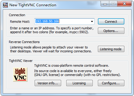
2. In the window that opens, enter the VNC password (the default is root), and then click OK, as shown in Figure 75.
Figure 75 Authenticating to VNC server
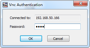
A VNC session is established between the VNC client and VNC server. The VNC client displays the server screen.
You can view the established VNC session from the Remote Services > Services page of HDM. The IP address for the VNC session is the IP address of the VNC client.
Figure 76 VNC session information
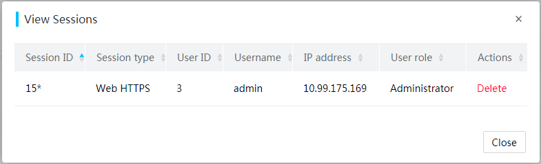
3. Operate the server as needed.
Configure the VNC login password
Use this feature to configure the settings of passwords for VNC client login. By default, the password is root.
Procedure
1. In the navigation pane, select Remote Services > Remote Console.
2. In the work pane, click the VNC tab, as shown in Figure 77.
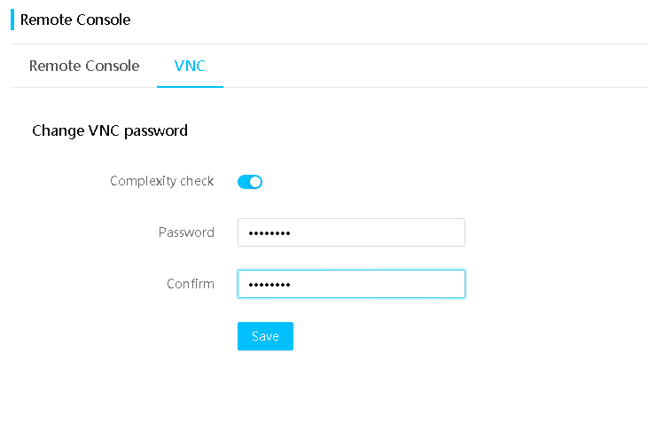
3. (Optional.) Select Enable for Complexity check.
4. Enter a new password and confirm the new password.
5. Click Save.
Parameters
Complexity check: Disable or enable password complexity check.
· If this feature is disabled, passwords must meet the following basic complexity requirements:
¡ 1 to 8 characters in length.
¡ Case sensitive. Valid characters are letters, digits, spaces, and special characters `~!@#$%^&*()_+-=[]\{}|;':",./<>?
· If this feature is enabled, passwords must meet the following enhanced complexity requirements:
¡ 8 characters in length.
¡ Case sensitive. Valid characters are letters, digits, spaces, and special characters `~!@#$%^&*()_+-=[]\{}|;':",./<>?
¡ Must contain characters from at least two of the following categories: uppercase letters, lowercase letters, and digits.
¡ Must contain at least one space or special character.
Remote media mounting
Image mounting mounts image files from a remote device to the operating system of the server. With this feature, you do not need to copy image files to the server before you can mount them.
You can mount virtual media by using the remote console (see "Remote console") or the image mounting feature. The following describes how to use image mounting to mount remote media images files.
Mount remote media
Perform this task to mount remote media to the server's operating system.
Prerequisites
Before you configure remote media image mounting, perform the following tasks:
1. Verify that the image files to be mounted are in correct format.
A CD/DVD image file must use the .iso extension, and floppy and HD(drive) image files must use the .img or .ima extension.
A floppy disk image file cannot exceed 1.44 MB.
2. Make sure the number of CD/DVD image files does not exceed 400 and the total number of floppy image files and HD(drive) image files does not exceed 400 in the source directory on the NFS or CIFS server. The length of each image file name is less than 128 characters.
3. Make sure your user account has the administrator or operator role or the remote media privilege. If the account is neither an administrator nor an operator, and does not have the remote media privilege, contact the administrator to obtain the privilege.
4. Make sure the desired virtual media services have been enabled for your user account. If they are not enabled, contact the administrator. You can use CD-Media and HD-Media to mount two image files and use FD-Media to mount only one media.
Restrictions and guidelines
· After enabling remote media redirection, when you modify advanced settings, make sure all remote media redirections stop, and images mounted to the remote console are disconnected.
· The server address supports both IPv4 and IPv6 addresses. IPv6 link-local addresses are not supported.
Procedure
1. Set up the image mounting environment. For more information, see "Configure virtual media."
2. In the navigation pane, select Remote Services > Virtual Media, as shown in Figure 78.
Figure 78 Accessing the remote media mounting page
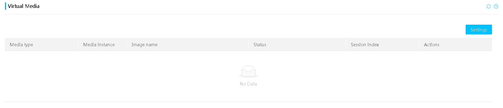
3. To open the operation wizard, click the ![]() icon on the upper right corner of the
page. Continue clicking Next to follow the guidance. After the operation is completed, click Finish in the
wizard. To close the wizard, click the cross on the upper right corner of the
wizard.
icon on the upper right corner of the
page. Continue clicking Next to follow the guidance. After the operation is completed, click Finish in the
wizard. To close the wizard, click the cross on the upper right corner of the
wizard.
4. In the work pane, click Settings.
5. On the page that opens, enable remote media, select media types, and then click OK, as shown in Figure 79.
¡ If you select NFS as the shared file system, enter the server address and source path.
¡ If you select CIFS (Samba) as the shared file system, enter the server address, source path, username, password, and domain name. The domain name field is optional.
As a best practice to avoid image mounting failure, do not enter unnecessary special characters for media information including the image file name, such as pound signs (#), asterisks (*), and semi-colons (;).
|
|
IMPORTANT: If remote media mounting has already been enabled, the media settings cannot be modified unless you stop all remote media mountings and disconnect all mounted images on the remote console. |
Figure 79 Configuring media mounting settings
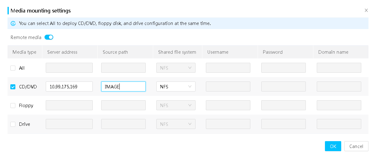
6. Select an image file from the remote media list, and then click Start.
To unmount the image file, click Stop.
Figure 80 Starting or stopping remote media mounting
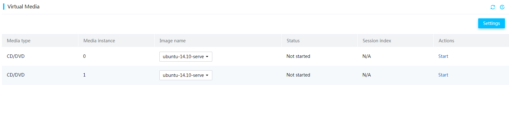
Parameters
· Media type: Type of the remote media, including CD/DVD, floppy, and disk (which includes both HDD and SSD).
· Status: Remote media mounting status, including Started and Not started. Common reasons for the Not started status include the following:
¡ Opening error—The image file is invalid.
¡ Not started— Max number of login sessions reached.
¡ Connection lost—The virtual media service has failed.
¡ Access error—The virtual media service is not enabled.
¡ Session terminated—The virtual media session is terminated.
· Session index: Index of the remote media mounting session.
Disable remote media
1. In the navigation pane, select Remote Services > Virtual Media.
2. In the work pane, click Settings.
3. In the dialog box that opens, select Disable for the remote media, and then click OK, as shown in Figure 79.
SNMP
Simple Network Management Protocol (SNMP) is an Internet protocol used for remote management and operations. It allows users to manage devices of different vendors with different physical characteristics and interconnection technologies in the network through NMS. For example, monitor device status, collect statistics, and perform troubleshooting.
Perform this task to configure SNMP settings, including SNMP version, read-only community string, and read/write community string.
Restrictions and guidelines
The SNMP SET operation is not supported if the read/write community string is empty.
The read/write community string cannot be the same as the read-only community string.
The read/write community string and read-only community string are displayed in ciphertext format from the Web interface.
Configure SNMP settings
1. In the navigation pane, select Remote Services > SNMP.
2. In the work pane, configure SNMP settings:
a. Select an SNMP version.
b. Select whether to enable the long community string feature.
c. Select Edit read-only community string or Edit read/write community string, and enter or delete the read-only or read/write community string.
3. Click Save.
Figure 81 Configuring SNMP settings
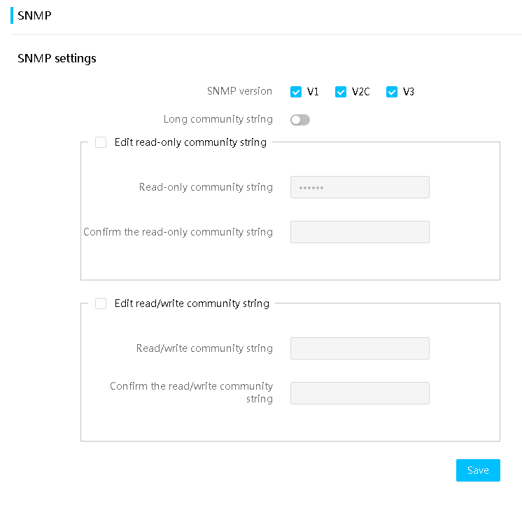
Configure SNMPv3 user settings
1. On the top navigation bar, click Remote Services.
2. In the left navigation pane, select SNMP.
The SNMPv3 user section displays the local users that are enabled with the SNMPv3 privilege.
3. Click Edit in the Actions column for a user.
4. In the dialog box that opens, edit the SNMPv3 privilege of the user:
a. (Optional.) Enter the SNMPv3 independent password.
b. Select SNMPv3 read or write permission.
c. Select SNMPv3 authentication protocol and privacy protocol. Privacy protocols AES192 and AES256 can be used only in combination with authentication protocol SHA256, SHA384, or SHA512.
5. Click OK.
Parameters
· SNMP version: Select an SNMP version available for SNMP GET and SET operations. Options include v1 and v2c and v3.
· Long community string: Select whether to enable the long community string feature. This feature is disabled by default.
If you enable the long community string feature, the value range for the community strings is 16 to 32 characters. If you disable the long community string feature, the value range for the community strings is 1 to 32 characters. You can leave the read/write community string empty, regardless of whether the long community string feature is enabled.
· Read-only community string: Enter the read-only community string for security authentication. By default, this field is empty but the default read-only SNMP community string is rocommstr.
· Read/write community string: Enter the read/write community string for security authentication. By default, no read/write SNMP community string is specified.
· User engine ID: Uniquely identifies SNMP agent entity enabled with the current user.
· SNMPv3 independent password: Enter the password to enable the SNMPv3 privilege. By default, the independent password is the same as the local user password. Follow these guidelines when you configure an SNMPv3 independent password:
¡ The password is a string of 8 to 40 characters. Spaces and backslashes (\) are not allowed.
¡ The password must meet the advanced password policy requirements for local user passwords.
¡ If the local user password contains spaces or backslashes (\), you must specify a new SNMPv3 independent password.
· SNMPv3 authProtocol: Select the SNMPv3 authentication protocol. Options include SHA, MD5, SHA256, SHA384, and SHA512.
· SNMPv3 privProtocol: Select the SNMPv3 privacy protocol. Options include DES, AES, AES192, and AES256.
Remarks
The Read-only community string and Read/write community string fields can contain only letters, digits, and special characters`~!@$%^&*()_+-=[]{}|:,./?
Fast system installation
This feature allows you to select a specified image file from Network File System (NFS) or SAMBA Common Internet File System (CIFS) to fast install the specified operating system.
Restrictions and guidelines
· This feature only completes specific image transfers in BMC. After the image transfer is completed, access the BIOS Setup Utility for subsequent system installation operations.
· Only administrators, operators, and users that have the remote media privilege can configure fast system installation.
· If you disable a fast system installation service that is progress, the current service will be terminated. If you enable the service again, you must re-configure the service settings.
· Fast system installation is not supported in Legacy mode.
· As a best practice, use this feature through the dedicated network port, because the transmission rate of the shared network port is slower, which might cause this feature to fail. To use the shared network port, you can improve the mirroring transmission rate by limiting the network connection speed to 100 Mbps.
· The operation systems that support fast system installation are as shown in Table 12.
Table 12 Supported OS types and names
|
OS type |
OS name |
|
RHEL |
RHEL-7.6 Server.x86_64 |
|
RHEL-7.7 Server.x86_64 |
|
|
RHEL-7.8 Server.x86_64 |
|
|
RHEL-8-0-0-BaseOS-x86_64 |
|
|
RHEL-8-1-0-BaseOS-x86_64 |
|
|
RHEL-8-2-0-BaseOS-x86_64 |
|
|
RHEL-8-3-0-BaseOS-x86_64 |
|
|
RHEL-8-4-0-BaseOS-x86_64 |
|
|
RHEL-8-5-0-BaseOS-x86_64 |
|
|
RHEL-8-6-0-BaseOS-x86_64 |
|
|
RHEL-9-0-0-BaseOS-x86_64 |
|
|
CentOS |
CentOS-8-BaseOS-x86_64 |
|
CentOS-8-1-1911-x86_64-dvd |
|
|
CentOS-8-2-2004-x86_64-dvd |
|
|
CentOS-8-2-2004-x86_64-dvd |
|
|
CentOS-8-3-2011-x86_64-dvd |
|
|
CentOS-8-4-2105-x86_64-dvd |
|
|
CentOS-8-5-2111-x86_64-dvd |
|
|
SLES |
SLE-15 |
|
VMware ESXi |
ESXI-7.0 |
|
ESXI-8.0 |
|
|
iFIST |
H3Linux8 |
|
H3Linux-Release |
|
|
H3Linux-2.0.1-x86_64 |
|
|
H3Linux-2.0.2-x86_64 |
|
|
Kylin |
Kylin-Server-10 |
|
CAS |
CAS-x86_64 |
|
Rocky |
Rocky-8-6-x86_64-dvd |
|
Oracle |
OL-8-4-0-BaseOS-x86_64 |
|
OL-8-6-0-BaseOS-x86_64 |
|
|
OL-9-0-0-BaseOS-x86_64 |
Procedure
1. On the top navigation bar, click Remote Services.
2. In the left navigation pane, select Fast System Installation.
3. Enable or disable fast system installation and select the image type.
¡ If you select NFS, you must also the server address, file path, and image name.
¡ If you select CIFS, you must also specify the server address, file path, image name, username, and password.
Figure 82 Fast System Installation
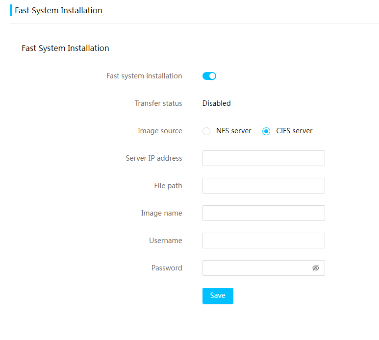
4. Click Save.
5. Restart the BIOS for the configuration to take effect.
Parameters
· Fast system installation: Enable or disable the fast system installation feature.
· Transfer status: Displays the current status of image transfer.
¡ Disabled: Image transfer is not enabled or is terminated.
¡ Image transfer finished: The previous transfer has finished.
¡ Waiting for image transfer: Image transfer is enabled and the system is waiting for the BIOS to restart to trigger the transmission.
¡ Image transfer in progress: Image transfer is enabled and triggered.
· Image source: Select NFS or CIFS.
· Server address: Specify the image file server address. Both IPv4 and IPv6 addresses are supported.
· File path: Specify the image file path. The file path cannot exceed 256 characters and special characters {}()<>&*`|=?;[]$-#~!"%:+,'\ are not allowed.
· Image name: Specify the image file name. The file name cannot exceed 128 characters, must end with .iso, and cannot contain semicolons (;), pound signs (#), or asterisks (*).
· Username: Enter the username of the Samba account. The username cannot exceed 256 characters and only letters, digits, and underscores (_) are allowed. This field is available only for CIFS (SAMBA) servers.
· Password: Enter the password of the Samba account. The password cannot exceed 32 characters and special characters "`,$'\ are not allowed. The field is available only for CIFS (SAMBA) servers.
O&M diagnosis
Logs
Manage the event log
Perform this task to configure the log policy, and view, download, or clear log entries.
Restrictions and guidelines
When the event log reaches the maximum size (1500), logging action on new events depends on the event log policy.
After all event log entries are deleted, the system automatically generates a log entry that records the deletion.
Procedure
1. On the top navigation bar, click O&M Diagnosis.
You are placed on the Logs page.
2. On the Event Log tab, select an event log policy from the Log policy field.
3. In the work pane, use one of the following methods to filter events:
¡ Select a severity level of the events.
¡ Select a sensor type.
¡ Select or customize a period when the events generated.
¡ Enter your keywords.
4. To filter events based on keywords, enter
the keywords, and then click the query icon ![]() .
.
5. To clear all specified filter criteria, click Reset.
6. To save event log entries to a .csv file, click Save.
7. To delete all event log entries, click Delete All.
The deleted event log entries cannot be restored.
Figure 83 Managing the event log
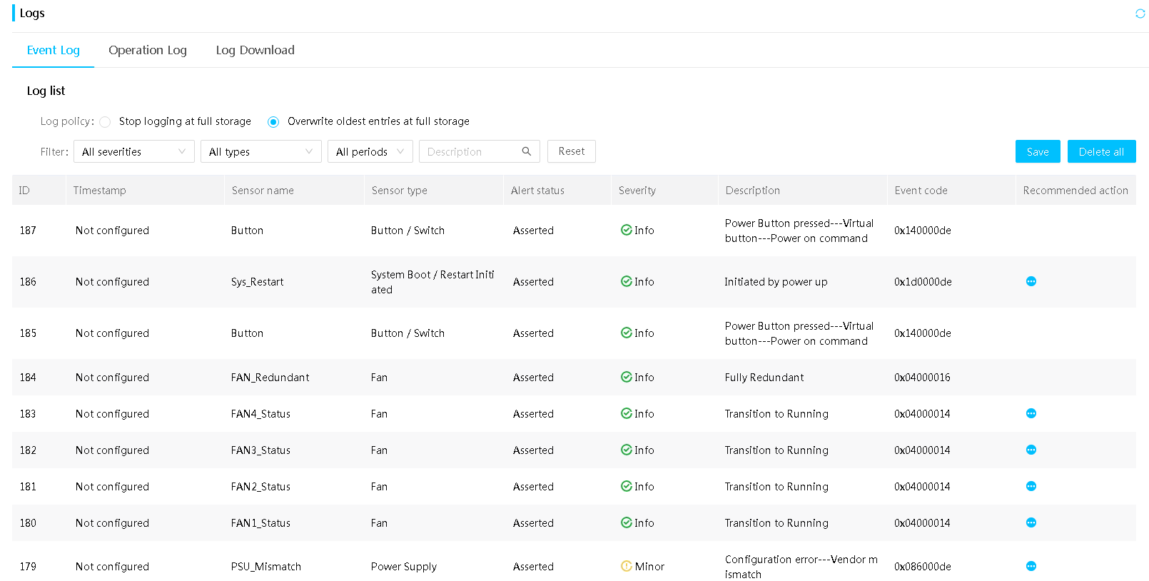
Parameters
· Stop logging at full storage: The system stops logging on new events when the event log fills up.
· Overwrite oldest entries at full storage: The system overwrites oldest entries with new log entries when the event log fills up.
· ID: Event number. Events are numbered in chronological order. By default, the events in the event list are sorted by event number in ascending order.
· Timestamp: Date and time when the event was logged.
· Alert status: Alarm status of the event, including Cleared and Triggered.
· Severity: Severity level of the event.
¡ Info—The event does not adversely affect the system. No action is required. Examples of informational events include expected state change events and alarm removed events.
¡ Minor—The event has minor impacts on the system. Prompt action is required to avoid an escalation in severity.
¡ Major—The event might cause part of the system to fail and result in service interruption. Immediate action is required.
¡ Critical—The event might result in system outage or power failure. Immediate action is required.
· Event code: Event code that identifies a system event in HDM.
· Recommended action: Actions recommended for a system event.
Manage the operation log
The operation log includes audit log entries, firmware update log entries, hardware update log entries, and configuration log entries.
· Audit log entries record HDM administrative events, including access to HDM and remote console startup.
· Firmware update log entries record HDM firmware updates as well as their results.
· Hardware update log entries record hardware updates as well as their results, for example, the updates of CPUs, memory, drives (including NVMe drives), and power supplies.
· Configuration log entries record user configuration operations as well as their results.
Procedure
1. On the top navigation bar, click O&M Diagnosis.
You are placed on the Logs page.
2. Click the Operation Log tab.
3. In the work pane, select a log type or a result to filter operation log entries as follows:
¡ To display operation log entries of a particular type, select that log type from the All types list.
¡ To display operation log entries of succeeded or failed tasks, select a corresponding result from the All results list.
4. To save operation log entries to a .csv file, click Save.
5. To delete all operation log entries, click Delete All.
The deleted log entries cannot be restored. Please use this feature with caution.
After the deletion, the system generates a log deletion log message.
Figure 84 Managing the operation log
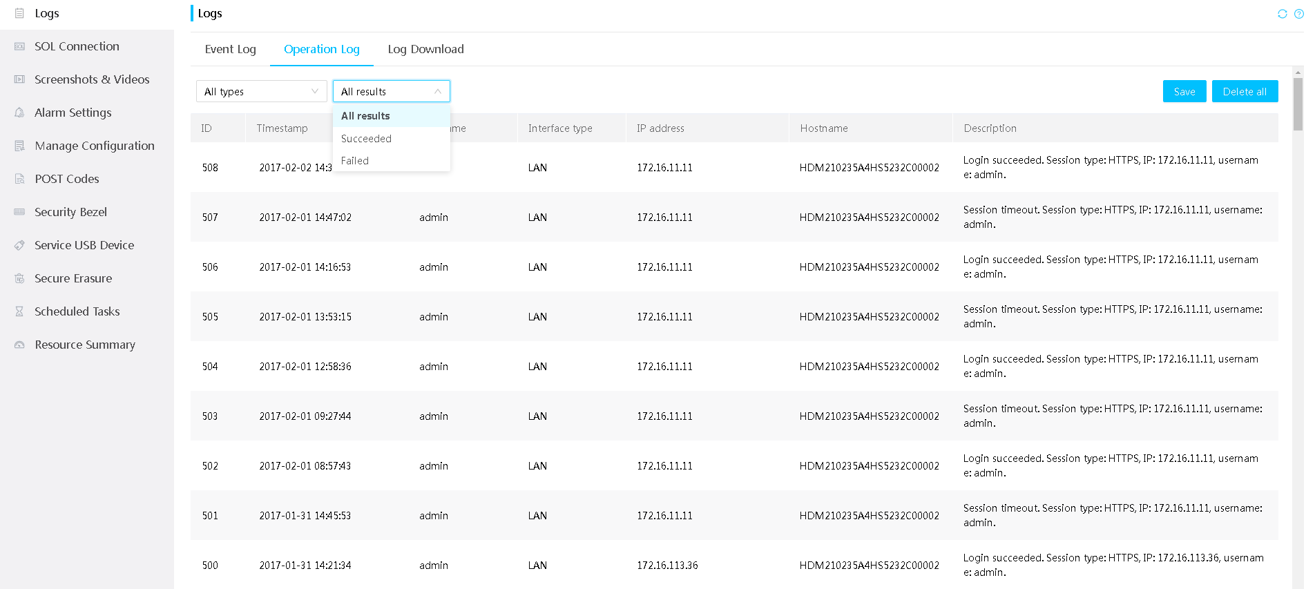
Parameters
· ID: Operation log entry number. Operations are numbered in chronological order. By default, the operations in the operation list are sorted by operation log entry number in ascending order. The system can display a maximum of 1000 operation log entries.
· Timestamp: Date and time when the operation was logged.
· Username: Enter a username for HDM login.
· Interface type: Type of the interface through which the operation was performed.
· IP address: User IP address.
· Host name: HDM host name.
· Description: Description of the log entry.
Download log
Perform this task to download Smart Diagnosis System (SDS) logs of the server. The SDS log includes HDM event log, HDM operation log, device information, operating parameters, and internal diagnostic information.
By decoding the collected SDS logs, users can comprehensively locate and analyze issues that occur to the server.
To decode SDS logs, contact Technical Support. As a best practice, add contact information at log downloading.
Restrictions and guidelines
Simultaneous log downloading by multiple users is not supported.
The downloaded log entries are saved in an .sds file folder. For more information about files in the file folder, see "Appendix A Downloaded log files."
Procedure
1. On the top navigation bar, click O&M Diagnosis.
You are placed on the Logs page.
2. Click the Log Download tab.
3. Configure Default download or Download all as needed:
¡ To download
the log entries for a period, select Default download and click the icon ![]() to set a time range in days. By default, this
feature downloads logs within the last 30 days.
to set a time range in days. By default, this
feature downloads logs within the last 30 days.
¡ To download all logs during the server life cycle, select Download all. This process might take a long time.
Figure 85 Downloading log
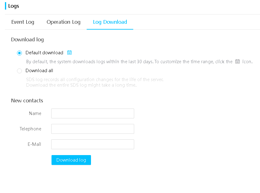
4. (Optional.) Add contact information, including the name, phone number, and email address.
5. Click Download log to download the log. This page displays a progress bar.
Figure 86 Viewing log downloading progress
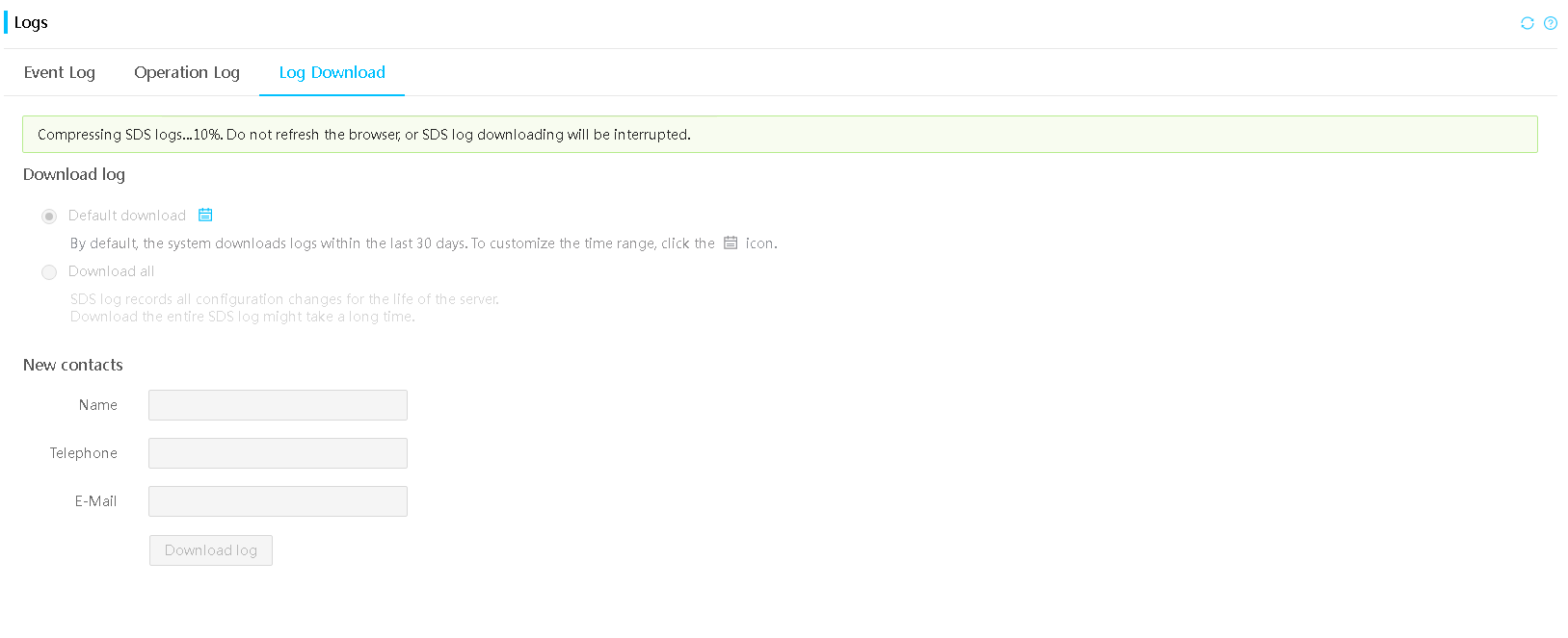
6. Save the displayed log entries to an .sds file on the local server.
SOL connection
Perform this task to select the serial port to connect to when the SOL feature is enabled.
Prerequisites
Before setting the SOL connection mode, make sure the SOL feature is disabled.
Procedure
1. On the top navigation bar, click O&M Diagnosis.
2. In the left navigation pane, select SOL Connection.
3. In the work pane, select a serial port from the SOL connection mode field.
4. Click Save.
Figure 87 Setting the SOL connection
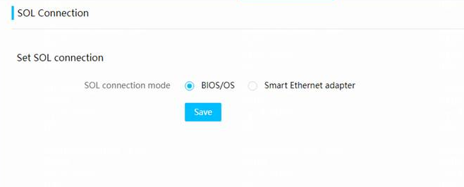
Parameters
· BIOS/OS: Connects to the BIOS or OS serial port.
· Smart Ethernet adapter: Connects to the serial port of the smart Ethernet adapter. Only some smart Ethernet adapters support serial port connection.
Screenshots & videos
Enable video recording
This feature records the server status upon occurrence of severe operating system events, including crash, restart, and shutdown. You can replay these videos to analyze or troubleshoot the recorded events.
Prerequisites
Make sure the KVM service has been enabled for your user account. If KVM is not enabled, contact the administrator.
If the remote console is open when an event triggers video recording, video recording will fail.
Procedure
1. On the top navigation bar, click O&M Diagnosis.
2. In the left navigation pane, select Screenshots & Videos.
3. In the work pane, click Configure.
4. In the dialog box that opens, enable video recording.
5. Set the video length. The value range is 15 to 255 seconds.
6. Select types of events to be recorded: crash, restart, or shutdown.
Crash event recording is available for Windows and Linux operating systems.
7. Click Save.
Figure 88 Configuring video recording
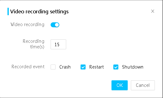
Play and manage videos
On the video replay page, you can play, download, and delete the recorded videos.
The system supports a maximum of three video files. If three video files already exist, a new video file overwrites the earliest one. The file creation time is recorded in the file properties.
Restrictions and guidelines
If the operating system was in sleep state when the event occurred, HDM displays a no signal message in place of the video.
Procedure
1. On the top navigation bar, click O&M Diagnosis.
2. In the left navigation pane, select Screenshots & Videos.
3. In the Video files section, click the video to be played.
4. To download a video, click Download after the video is loaded.
5. To close a video, click Cancel.
6. To delete a video, click the icon ![]() in the lower right corner of the video,
and then click OK in the dialog box that opens.
in the lower right corner of the video,
and then click OK in the dialog box that opens.
Figure 89 Playing videos
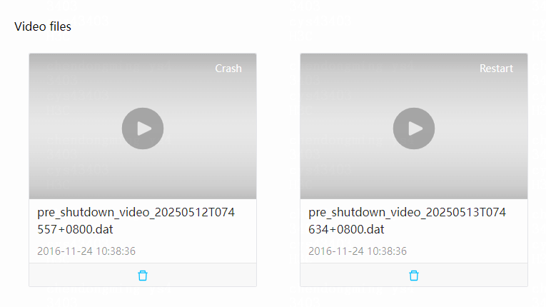
View BSoD screenshots
This feature automatically takes a bluescreen of death (BSoD) screenshot upon a system crash of Windows for future troubleshooting. HDM can save a maximum of 10 BSoD screenshots, which are named with a sequence number and the screenshot time. When the maximum number of screenshots is reached, a new BSoD screenshot overwrites the oldest one.
Prerequisites
Make sure the KVM service has been enabled for your user account. If KVM is not enabled, contact the administrator.
Restrictions and guidelines
If the server is installed with a non-Windows operating system, HDM also takes screenshots upon MCA triggers when the server detects an MCA error.
HDM takes screenshots of the FRB2 timeout trigger when the server detects a BIOS watchdog timeout.
Procedure
1. On the top navigation bar, click O&M Diagnosis.
2. In the left navigation pane, select Screenshots & Videos.
3. View the BSoD screenshots listed on the page.
Figure 90 Viewing BSoD screenshots
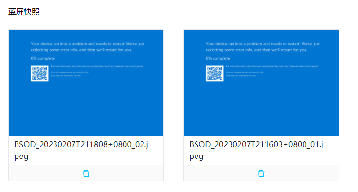
Alarm settings
Use this feature to perform the following operations:
· Configure alert policies on the server when an error occurs, including NMI control and MCA policy.
· Send emails, SNMP traps, or syslog messages to notify the concerned server administrative staff members of server events for prompt action.
Manage alert polices
Enable NMI debug
This feature enables the operating system debugger to help you debug software lock-up issues by generating non-maskable interrupts.
Restrictions and guidelines
The Non Maskable Interrupt (NMI) debug feature is intended for debugging only. Do not use this feature if the server is operating correctly.
Prerequisites
Verify that the operating system can handle NMIs. If the operating system cannot handle NMIs, using NMI debug might cause the operating system to crash.
Procedure
1. On the top navigation bar, click O&M Diagnosis.
2. In the left navigation pane, select Alarm Settings.
3. In the NMI debug section of the work pane, click Execute.
Figure 91 Enabling NMI debug

Set the MCA policy
Machine Check Architecture (MCA) is a mechanism that enables error reporting and error recovery. MCA policy defines whether a host requires a restart when HDM detects uncorrectable IERR errors (including CPU, memory, and PCIe errors) or fatal errors on the host.
Restrictions and guidelines
The MCA policy does not affect the OS restart policy.
Procedure
1. On the top navigation bar, click O&M Diagnosis.
2. In the left navigation pane, select Alarm Settings.
3. In the MCA policy section of the work pane, select Yes or No from the Restart upon IERR occurrence field.
¡ Yes: When HDM detects uncorrectable IERR errors or fatal errors, the system restarts the host automatically.
¡ No: When HDM detects uncorrectable IERR errors or fatal errors, the system does not restart the host.
4. Click Save.
Figure 92 Setting the MCA policy
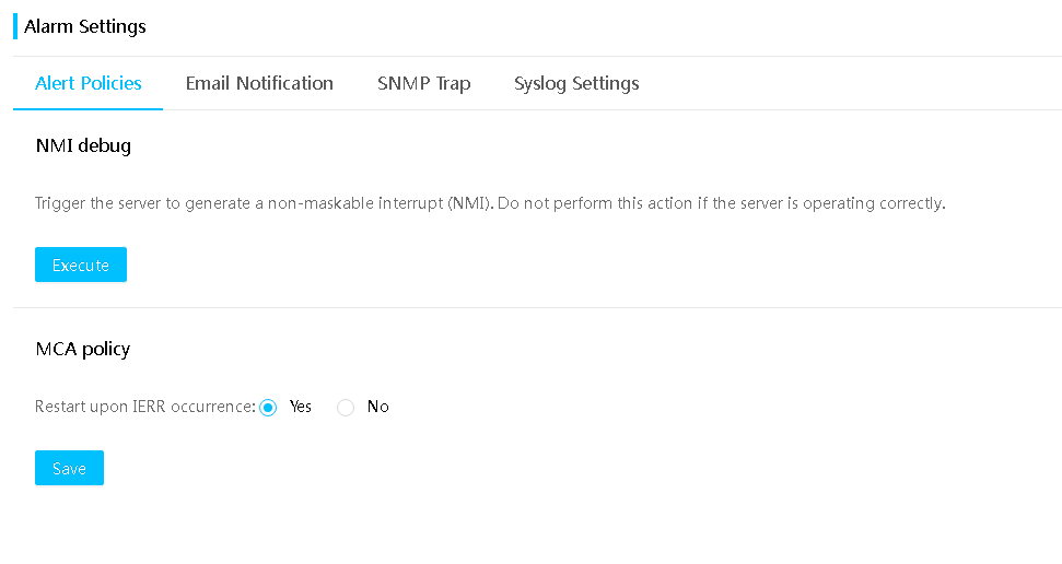
Manage alert emails
HDM sends alert emails through Simple Mail Transfer Protocol (SMTP). To send an alert email to a user, you must configure SMTP, specify that user as an email recipient, and configure the alert policy for that user.
Prerequisites
Make sure you have specified an email address in the user account for the email recipient. For information about adding an email address for a user account, see "User management."
Set up SMTP for alert emails
1. On the top navigation bar, click O&M Diagnosis.
2. In the left navigation pane, select Alarm Settings.
3. Click the Email notification tab.
Figure 93 Email notification tab
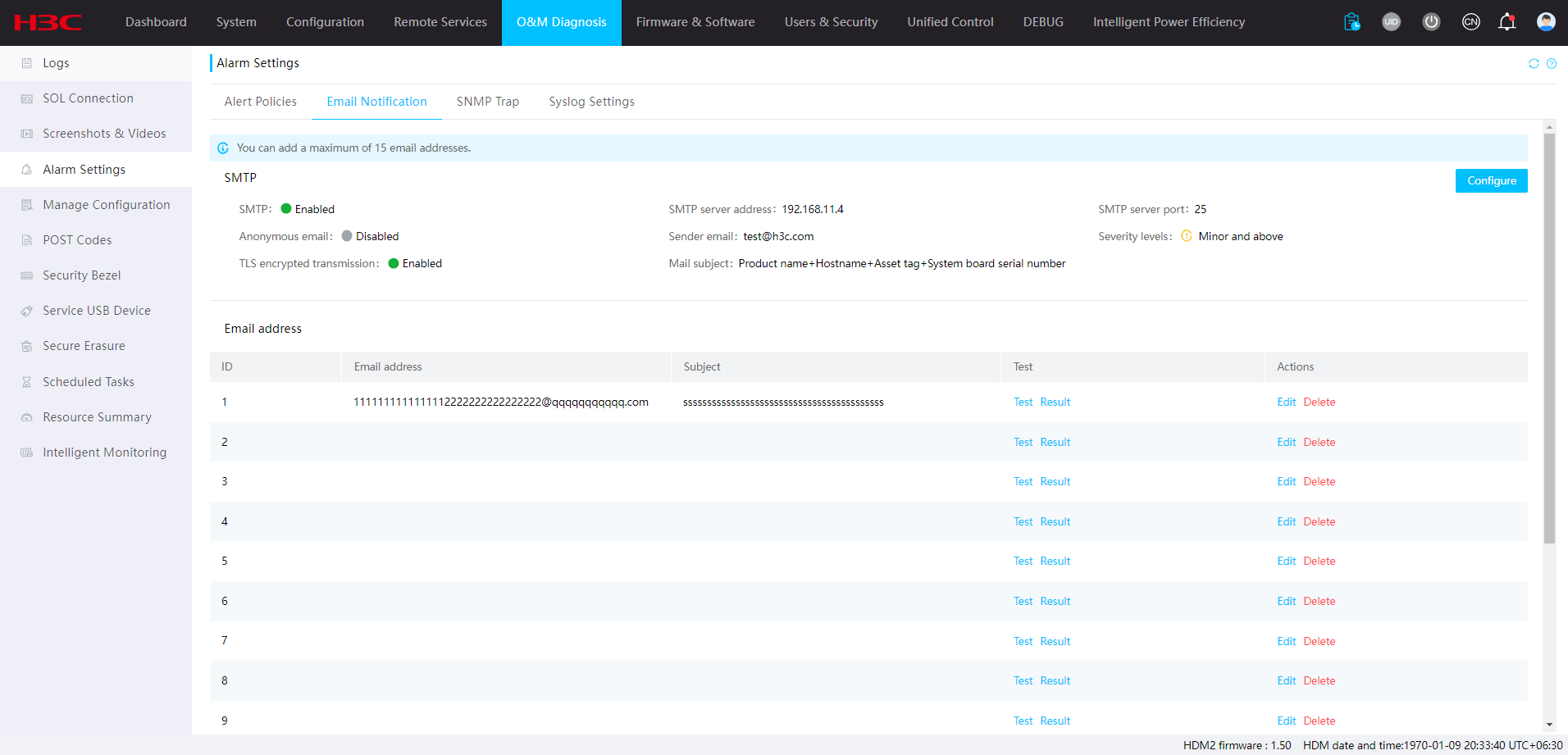
4. In the SMTP section, click Configure.
5. In the dialog box that opens, configure SMTP:
¡ Select Enable for SMTP.
¡ Enter the SMTP server address and port number.
¡ To send alert emails as anonymous emails, select Enable for Anonymous email. To send alert emails with sender identity information, clear Enable for Anonymous email and enter the username and password for connecting to the SMTP server. The username can contain only letters, digits, underscores (_), at signs (@), and dots (.).
¡ Enter the sender email address. Make sure the email service uses the SMTP mail server.
¡ Select severity levels. Options include Info and above, Minor and above, Major and above, and Critical and above.
¡ To ensure data confidentiality and integrity during transmission, enable Transport Layer Security (TLS) encrypted transmission.
TLS encrypted transmission uses port 465 by default. To use the feature, you must import SMTP certificate and SMTP private key files to the SMTP server.
¡ Add email subjects. You can select multiple subjects for an email.
6. Click OK.
Figure 94 Setting up SMTP for alert emails
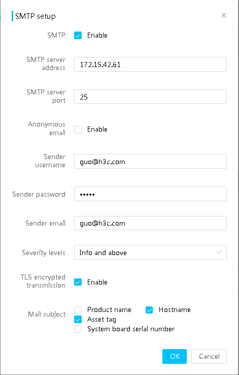
Add an alert email recipient
1. To have a user receive alert emails, you must specify an email address for that user when you set up the user account on the Users & Security > User Accounts page.
2. On the top navigation bar, click O&M Diagnosis.
3. In the left navigation pane, select Alarm Settings.
4. Click the Email notification tab.
5. Click Add.
6. In the dialog box that opens, select the ID, enter the recipient email address and subject.
Only letters, digits, and underscores (_) are supported for the email subject.
With an email subject added in SMTP settings, if you configure a subject again for the recipient settings, HDM displays two subjects during sending.
7. Click Test to send a test email, and then click Result to view the test result.
8. To edit a recipient, click Edit in the email recipient entry.
9. To delete a recipient, click Delete in the email recipient entry.
Manage SNMP traps
You can send server events in SNMP traps to an SNMP management workstation.
Configure SNMP trap settings
1. On the top navigation bar, click O&M Diagnosis.
2. In the left navigation pane, select Alarm Settings.
3. Click the SNMP trap tab.
Figure 95 SNMP trap tab

4. In the SNMP trap settings section, click Configure.
5. In the dialog box that opens, configure SNMP trap settings.
a. Select Enable for SNMP trap.
b. Select an SNMP trap mode. Options include Node mode, Event mode, or Event code mode.
c. Select an SNMP version. If SNMPv3 is selected, you must also specify an SNMPv3 user in the Choose trap v3 user field.
d. (Optional.) Enter the location of the server and contact information.
6. Click OK.
Figure 96 Configuring SNMP trap settings

Configure SNMP trap server settings
1. On the top navigation bar, click O&M Diagnosis.
2. In the left navigation pane, select Alarm Settings.
3. Click the SNMP trap tab.
4. In the SNMP trap server settings section, click Edit in a server entry.
5. In the dialog box that opens, configure SNMP trap server parameters.
Figure 97 Configuring SNMP trap server settings
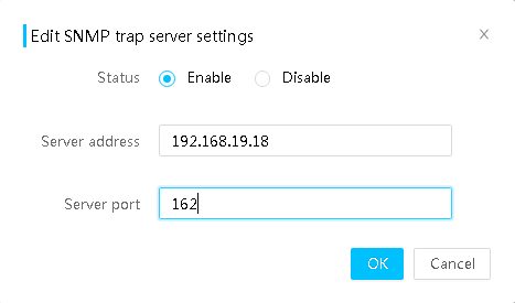
6. Click OK.
7. (Optional.) Click Test in a server entry to send a test email.
Parameters
· Node mode: Uses the OID of an SNMP node as the ID of a trap event. This is the default mode.
· Event mode: Uses the OID of the SNMP node that is in a mapping relationship with a trap event as the ID of the event.
· Event code mode: Uses the event code as the ID of the event. Information provided in this mode is more accurate.
· SNMP version: Select an SNMP version. Options include SNMPv1, SNMPv2c, and SNMPv3.
· Choose trap v3 user: Select the username used by the system to send SNMPv3 traps.
· System location: Enter the location of the server, a string of up to 31 characters.
· Contact: Enter contact information, a string of up to 31 characters.
· Trap community: Enter the trap community string for authentication on the manager. The trap community string can be empty. The value range is 1 to 31 characters. The default value is public.
· Severity levels: Select the severity levels. Options include Info and above, Minor and above, Major and above, and Critical and above.
· No.: Entry number. You can specify a maximum of eight servers, one server in each entry. This field cannot be edited.
· Status: Indicates whether trap notification is enabled for the specified server.
· Server address: IP or domain address of the destination host. IPv6 local link addresses and IPv6 multicast addresses are not supported.
· Server port: Enter the port number at which the destination host receives SNMP traps. The value range is 1 to 65535. The default port number is 162.
Remarks
The System location, Contact, and Trap community fields can contain only letters, digits, and the following special characters:
` ~ ! @ $ % ^ & * ( ) _ + - = [ ] { } | : , . / ?
Manage syslog settings
Perform this task to use syslog messages to report operation logs, event logs, security logs, sensor logs, and serial port logs to destination hosts:
Restrictions and guidelines
After you disable Syslog, all tunnels for sending logs are disabled. When you enable Syslog again, the tunnels restore to the states before you first disable Syslog.
Prerequisites
Before enabling syslog, make sure a syslog server is available. For more information, see "Set up a syslog server."
Configure alarm log notification settings
1. On the top navigation bar, click O&M Diagnosis.
2. In the left navigation pane, select Alarm Settings.
3. Click the Syslog Settings tab.
Figure 98 Syslog Settings tab
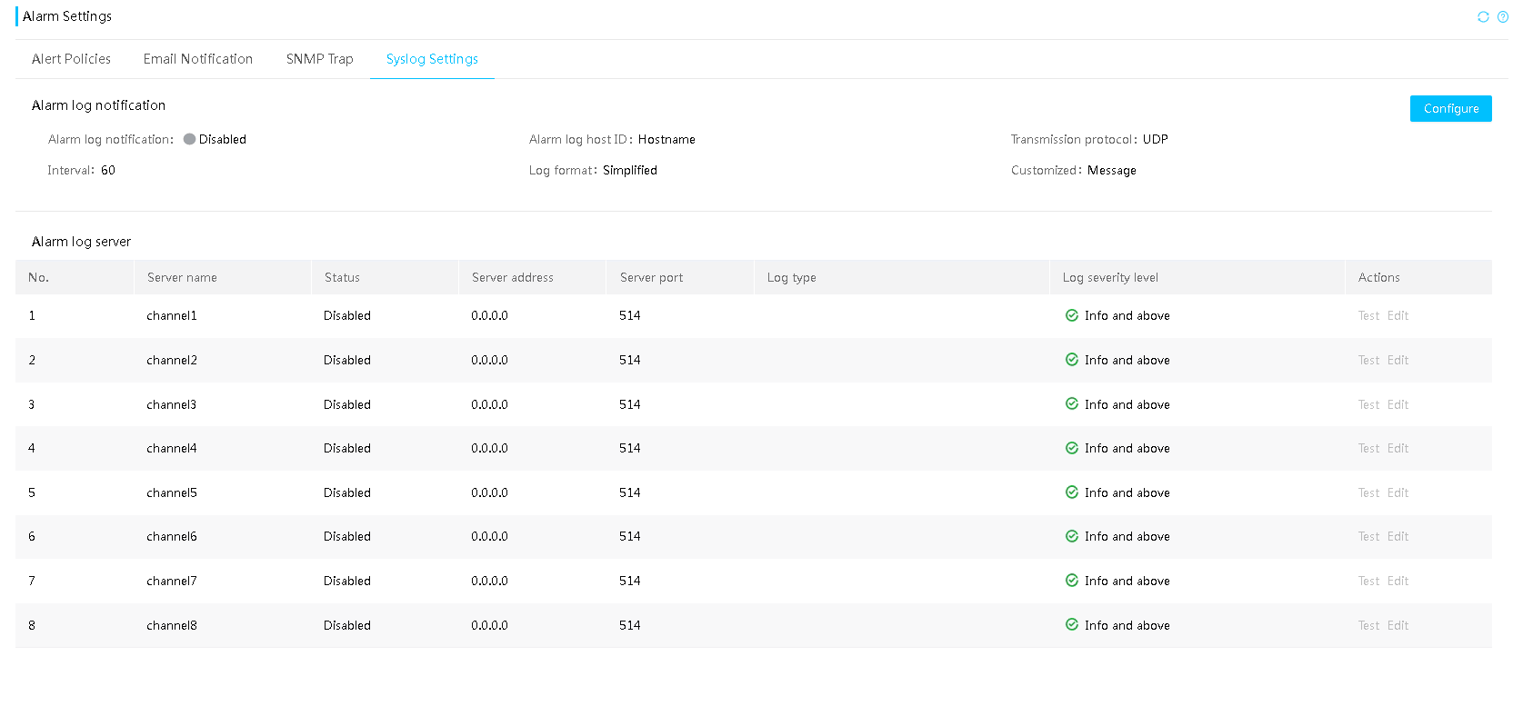
4. In the Alarm log notification section, click Configure, and then perform the following tasks:
a. Enable alarm log notification.
b. Select an alarm log server identifier.
c. Select a transmission protocol.
If you select TLS, you must select an authentication mode, and upload the CA certificate, local certificate, and private key file.
d. Specify the log sending interval. This item takes effect only for sensor logs.
e. Select the log format. You can select the RFC format (including RFC3164 and RFC5424) or a simplified format that supports customizing timestamp and host name. You can select multiple log formats.
f. Click OK.
Figure 99 Configuring alarm log server settings

Configure alarm log server settings
1. On the top navigation bar, click O&M Diagnosis.
2. In the left navigation pane, select Alarm Settings.
3. Click the Syslog Settings tab.
4. In the Alarm log server settings section, click Edit in a server entry, and then perform the following tasks:
a. Enable the tunnel for sending the current alarm logs.
b. Enter the server name.
c. Enter the server address, both IP address and domain name are supported.
d. Enter the port number.
e. Select one or multiple types of logs to be reported.
f. Select the log level. This item is supported only for event logs.
g. Click OK.
Figure 100 Configuring alarm log server settings

Parameters
· Alarm log host ID: Select an alarm log server identifier. Options include Host name, System board serial number, Asset tag, and Product serial number.
· Transmission protocol: Select the transmission protocol used for syslog message transmission. Options include:
¡ TCP—A connection-oriented protocol that requires establishing connection between the sender and the receiver before data transmission.
¡ UDP—A message-oriented protocol that does not require establishing connection between the sender and the receiver before data transmission.
¡ TLS—A connection-oriented protocol and provides privacy and data integrity between the sender and the receiver.
· Authentication mode: Select an authentication mode. Options include:
¡ One-way authentication: Authenticates only the alarm log server.
¡ Two-way authentication: Authenticates both the alarm log server and the client used for HDM login.
· CA certificate: Upload a CA certificate in PEM format to authenticate packets sent by the alarm log server.
· Local certificate: Upload a local certificate in PEM format whose information will be carried in packets sent to the alarm log server by HDM for the server to authenticate the client used for HDM login.
· Private key: Upload a private key file in PEM format to decrypt the local certificate.
· Interval: Specify the interval at which sensor information is reported, in the range of 10 to 2592000 seconds.
· No.: Entry number. You can specify a maximum of eight servers, one server in each entry.
· Server name: Name of the destination host that receives syslog messages, a case-sensitive string of 1 to 31 characters. Only letters, digits, dots (.), hyphens (-), underscores (_), and at signs (@) are allowed. This field is optional.
· Server address: Enter the IP address or domain name of the destination host. The default IP address is 0.0.0.0. A domain name cannot exceed 255 characters. An IPv6 local link address or IPv6 multicast address is not supported.
· Server port: Enter the port number at which the destination host receives syslog messages. The value range is 1 to 65535. The default port number is 514.
· Log type: Types of syslog messages to be reported. Options include Operation log, Event log, Security log, Serial port log, and Sensor log.
· Log severity level: Severity levels of alarm logs. Options include Info and above, Minor and above, Major and above, and Critical and above.
Manage configuration
Perform this task to import and export HDM, BIOS, or RAID configuration, and restore and view HDM factory defaults.
Restrictions and guidelines
To avoid HDM and operating system anomalies, do not perform any power actions on the server during the import process.
Do not refresh the webpage when configuration is being imported or HDM settings are being restored. If you refresh the page, HDM might fail to be accessed.
If configuration import fails, troubleshoot the issue that leads to the failure as instructed and then import the configuration again.
Configuration import overwrites the existing configuration with the configuration in the imported file.
To avoid import failure, when you modify the configuration file, please be cautious and make sure the configurations are valid.
RAID configuration import and export do not import or export storage controller configurations such as the RAID mode setting.
Support for configuration that can be imported or exported varies by device model.
To avoid import failure, make sure no one except for the current user is performing operations.
Export HDM, BIOS, or RAID configuration
Restrictions and guidelines
Make sure the storage controllers have been initialized before you export the RAID configuration.
PMC storage controllers do not support RAID configuration export.
Make sure the logical drives attached to the storage controllers are in normal state and no expansion, migration, rebuilding, or erasing task is being performed before you export the RAID configuration.
Before exporting RAID configuration, make sure the physical drives of a logical drive are the same media and a physical drive is used only by one logical drive.
If you import BIOS configuration when BIOS is staring up, the operation will not take effect. Do not import BIOS configuration at BIOS startup.
Procedure
1. On the top navigation bar, click O&M Diagnosis.
2. In the left navigation pane, select Manage Configuration.
3. In the Export configuration section, select the target configuration type from the Select type field.
4. Click Export.
Figure 101 Exporting HDM, BIOS, or RAID configuration
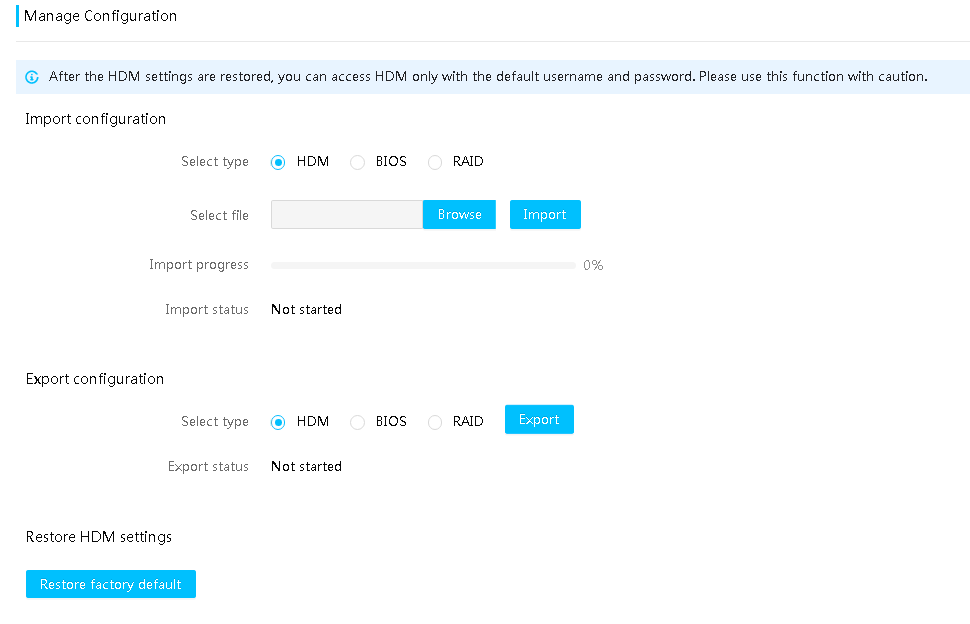
Import HDM, BIOS, or RAID configuration
General restrictions and guidelines
To avoid HDM and operating system anomalies, do not perform any power actions on the server during the import process.
If configuration import fails, troubleshoot the issue that leads to the failure as instructed and then import the configuration again.
To avoid import failure, make sure the other users are not operating the server from HDM before you import configuration.
To avoid import failure, when you modify the configuration file, make sure the configurations are valid.
Make sure you have deleted all the comment statements in the configuration file before the import.
If the password in the configuration to be imported is empty and the configuration is from a different server, you must add the password manually. The new password will take effect after the import.
Restrictions and guidelines for importing HDM configuration
Make sure the server model in the configuration file to import is consistent with the actual server model.
The import operation does not affect HDM configurations that are not covered by the configuration file to import.
The configuration takes effect directly after import. If you update network settings after importing HDM configuration successfully, the system will terminate the current browser connection. You are required to open a new browser and re-log in to HDM.
If the configuration to be imported includes HDM management IP settings, you cannot access HDM by using the current management IP address after the import. If a static IP address is imported, the IP address becomes the management address. If a DHCP-assigned address is imported, the server obtains a new IP address from the DHCP server and uses the address as the management address, and the address obtaining method changes to DHCP.
Restrictions and guidelines for importing BIOS configuration
Make sure the server model and hardware configuration (for example, storage controller and drive configuration) in the configuration file is consistent with the actual configuration.
For the imported BIOS configuration to take effect, restart the server after the import.
Restrictions and guidelines for importing RAID configuration
Make sure the server is powered on and the storage controller is in RAID mode before you import RAID configuration.
Make sure the server model and hardware configuration (for example, storage controller and drive configuration) in the configuration file is consistent with the actual configuration.
To avoid import failure, make sure the BIOS is in Setup stage and out-of-band management is correct for the storage controller from the Storage page.
To avoid import failure, clear existing RAID configuration from the BIOS before you import RAID configuration.
To avoid import failure, delete logical member drives whose slots are in the configuration file from the Storage page.
PMC storage controllers do not support RAID configuration import.
After a RAID configuration import, it takes about 40 seconds for the imported file to take effect.
Procedure
1. On the top navigation bar, click Remote O&M.
2. In the left navigation pane, select Manage Configuration, as shown in Figure 101.
3. In the Import configuration section, select HDM from the Select type field.
4. Select the target configuration file, and then click Import.
5. In the confirmation dialog box that opens, click OK.
Figure 102 Importing HDM, BIOS, or RAID configuration
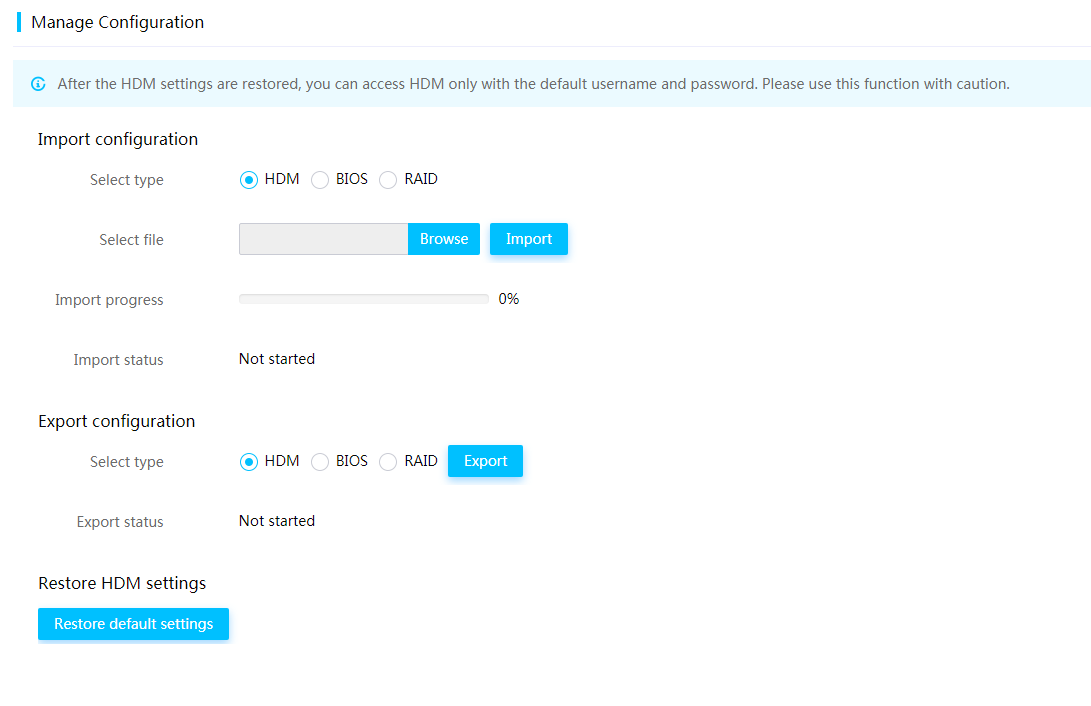
Restore HDM settings
|
|
CAUTION: · After HDM settings are restored, you can access HDM only with the default username and password. Use this function with caution. · Do not refresh the webpage when HDM settings are being restored. If you refresh the page, HDM might fail to be accessed. |
To restore HDM settings:
1. On the top navigation bar, click O&M Diagnosis.
2. In the left navigation pane, select Manage Configuration, as shown in Figure 101.
3. In the left navigation pane, select Manage Configuration.
4. In the Restore HDM settings section, perform one of the following tasks:
¡ Identify the configuration model of the server.
¡ To restore HDM to the factory defaults, click Restore factory defaults.
5. In the confirmation dialog box that opens, click OK.
HDM restarts after the settings are restored.
POST codes
The system generates power-on self-test (POST) codes to record its state in each phase of server startup. For more information about POST codes, contact Technical Support.
View POST codes
Restrictions and guidelines
If the system generates more than 512 post codes during startup, the HDM web interface only displays the most recent 512 post codes.
Procedure
1. On the top navigation bar, click O&M Diagnosis.
2. In the left navigation pane, select POST Codes.
3. In the work pane, view the generated timestamp, name, and description of the system POST codes.
Figure 103 Post codes
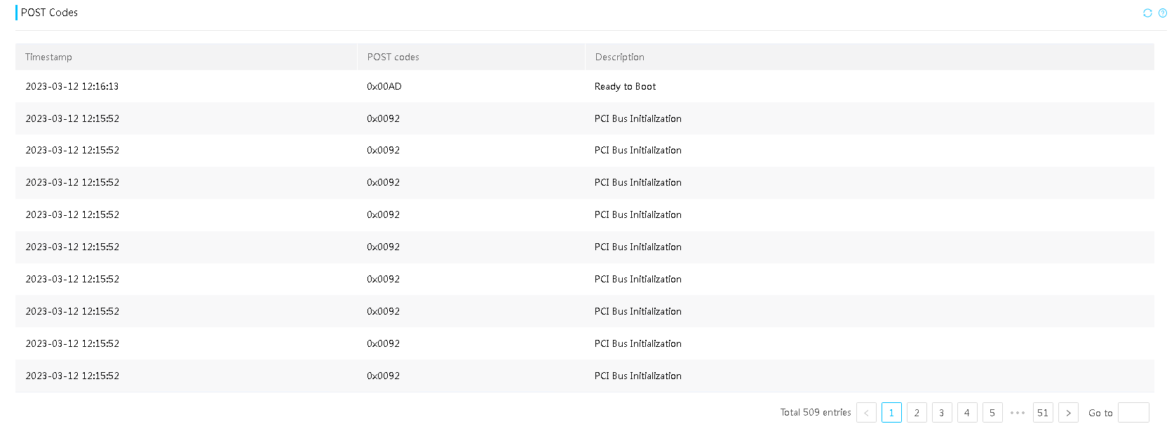
Parameters
· Timestamp—Time when the post code is generated.
· POST code of current phase—POST code for the current startup phase of the system.
Manage the intelligent security bezel
Perform this task to identify the presence status of the intelligent security bezel and configure security bezel settings.
Restrictions and guidelines
Support for the health status sync and the color setting of the decorative LEDs varies by device model.
Procedure
1. On the top navigation bar, click O&M Diagnosis.
2. In the left navigation pane, select Security Bezel.
3. Identify whether the intelligent security bezel is present.
4. If the intelligent security bezel is present, configure the security bezel settings as needed.
¡ If you set the decorative LED mode to Server status sync, the flashing mode and color of the decorative LEDs change as the server operation status changes.
¡ If you set the decorative LED mode to Custom, you can set the flashing mode and color of the decorative LEDs.
5. Click Save.
Figure 104 Managing the intelligent security bezel
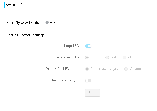
Parameters
· Decorative LEDs: Includes the following options: Bright, Soft, and Off. If you enable the decorative LEDs, select Soft as a best practice to decrease power consumption. Support for the Soft option varies by server model.
· Health status sync: Enables the decorative LEDs to flash based on the server health status. To use this feature, make sure the Server status sync option is selected. For more information, see the user guide for the server.
Manage service USB devices
A service USB device is a USB device burned with the image file of the UniTool. You can connect such a device by using the USB C-to-USB A adapter to the server to download SDS logs automatically and manage the service USB device from HDM as needed.
Restrictions and guidelines
· If a user is downloading SDS logs at the time you connect a service USB device, the system ejects the service USB device. You can wait for the ongoing downloading process to end and then reconnect the service USB device.
· Before connecting a service USB device, make sure the available space on the device is greater than 500 MB.
· During SDS log downloading, the server UID LED is in flashing blue and returns to the normal state when the downloading is complete.
· To avoid USB exceptions, do not forcibly remove an operating service USB device.
· To avoid USB exceptions, do not connect or remove a service USB device frequently.
· If you connect multiple service USB devices to the dedicated management port of the server, the server can identify only the first-connected one.
Procedure
1. On the top navigation bar, click O&M Diagnosis.
2. In the left navigation pane, select Service USB Device.
The page that opens displays the status of the service USB device.
3. Select whether to enable the dedicated management port.
4. Select whether to enable the service USB device.
5. Select whether to enable auto SDS log downloading.
6. Click Save.
7. If the service USB device is operating, wait for the operation to end and then reconnect the service USB device for the settings to take effect.
Figure 105 Managing service USB devices
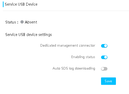
Parameters
· Status: Status of the service USB device. Options include Present, Absent, and Operating.
· Auto SDS log downloading: With this feature enabled, the service USB device automatically downloads SDS logs to its ServiceUdisk directory when you connect the device to a server.
Secure erasure
Perform this task to erase HDM, the BIOS, and storage data for the server to avoid data leakage when the server service life terminates or the server operation is terminated.
The secure erase feature depends on the license status. For more information about obtaining licenses, see "License management."
Restrictions and guidelines
|
|
CAUTION: · To avoid data loss, backup data in advance or make sure the data to be erased are of no use and can be erased. · To avoid erasing data by mistake, make sure you remove all external storage devices (including but not limited to mobile HDDs) from the server. |
If the data volume to be erased is large, the operation might take more than one day.
To ensure a successful erase, make sure the server uses iFIST-1.38 or later version.
Do not restart HDM or the server or modify the OS configuration information during erase.
For the BIOS and storage data, the server restarts automatically and then uses iFIST for erase. When the erase is complete, the server automatically restarts again with boot options configured before the erase.
If the server is powered off, power on the server before you erase the BIOS and storage data.
Once the erase starts, all HDM functions except for secure erasure are unavailable.
Secure erasure only erases data of drives identified by the OS.
Restart the server before you perform secure erasure on other storage components.
If secure erasure fails for a drive, use other methods to erase the data.
If you select multiple erasing objects that include HDM, HDM will restart after data erase for all objects is complete. To download and view the erasing result, re-log in to HDM.
If you erase HDM data, the system also erases hardware information for HDM Web interface and the BIOS information in HDM. To obtain these information, you must power off and power on the server.
Support for objects of secure erasure varies by server model.
Procedure
1. On the top navigation bar, click O&M Diagnosis.
2. In the left navigation pane, select Secure erasure.
Figure 106 Secure erasure page
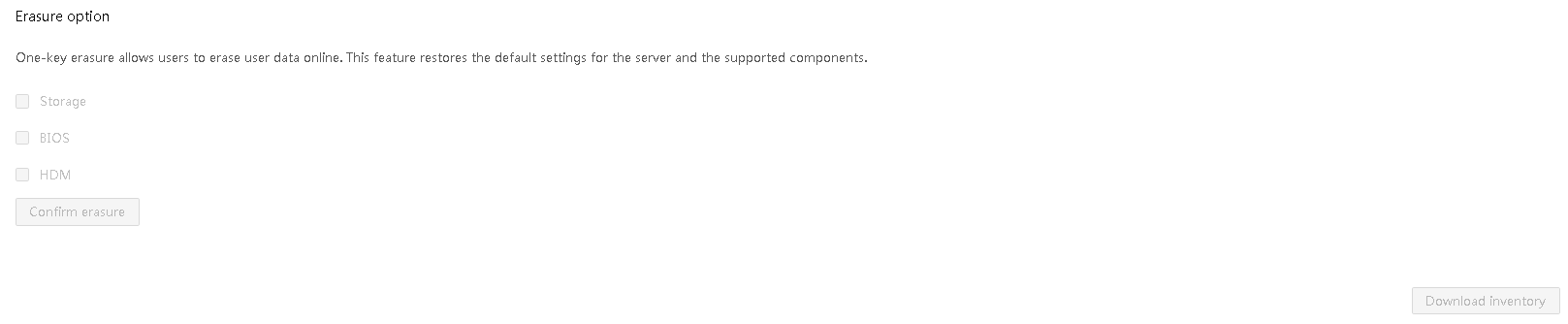
3. Select items from HDM, BIOS, and Storage to be erased.
4. Click Confirm erasure. In the dialog box that opens, enter the HDM login password, and then click OK.
5. View the erasure progress in Erasure progress.
6. When the erase is complete, click Download inventory to view the erase result. The available erase results and methods for the erase to take effect are shown in Table 13.
|
Item |
Erase result |
Method to take effect |
|
HDM |
Restore HDM factory defaults. SDS logs and flash card data are erased. |
HDM restarts automatically. |
|
BIOS |
· Restore to the BIOS default settings. · The administrator and user passwords for the BIOS are erased. The BIOS does not require a password for the user whose password is erased to enter the BIOS Setup utility at next restart. · The server power-on password is erased from the BIOS. |
Restart the server. |
|
No-volatile DRAM (NVDIMM) |
Data in NVDIMMs that are not in memory mode are erased. After erase, all NVDIMMs operate in memory mode. |
The server restarts automatically. |
|
Storage controller |
· All logical drives managed by the RSTe RAID controller and VROC module are deleted. · All logical drives managed by the following LSI storage controllers are deleted: ¡ HBA-LSI-9311-8i ¡ HBA-LSI-9500-16i ¡ HBA –LSI-9500-8i ¡ HBA-LSI-9540-8i ¡ If the LSI storage controller is in RAID mode before the deletion, the JBOD attribute of the storage controller will change to ON after the deletion. · All logical drives managed by the following PMC storage controllers are deleted: ¡ HBA-H460-B1 ¡ RAID-P4408-Mf-8i-2GB ¡ RAID-P2404-Mf-4i ¡ RAID-P460-B2 ¡ RAID-P460-B4 · All logical drives managed by the following MARVELL storage controllers are deleted: ¡ RAID-MARVELL-SANTACRUZ-2i |
The server restarts automatically. |
|
Drive |
All data in the drive are deleted. |
The server restarts automatically. |
|
SD card |
All data in the SD card are deleted. |
The server restarts automatically. |
Scheduled tasks
When upgrading firmware from the HDM Web interface, if you customize the upgrade time, HDM will establish a new timer task for firmware update.
Perform this task to view and modify all timer task information, including the type, state, last execution time, and description for the task.
Restrictions and guidelines
HDM deletes a scheduled task one hour after the task finished.
If the server cannot finish a scheduled task on time, the system keeps the task automatically unless you delete the task manually.
HDM supports a maximum of 20 scheduled tasks and a maximum of 10 scheduled upgrade tasks. When the number of scheduled tasks reaches the upper limit, a newly created task overwrites a task in Executed state. If the number of scheduled upgrade tasks already reaches 10, the creation of a new scheduled upgrade task fails. If all current tasks are in Waiting or Abnormal state, you must delete a current task to add a new one.
You can delete or modify only tasks in Waiting or Abnormal state, and cannot delete or modify tasks in Executed state.
Procedure
1. On the top navigation bar, click O&M Diagnosis.
2. In the left navigation pane, select Scheduled Tasks.
Figure 107 Scheduled Tasks page
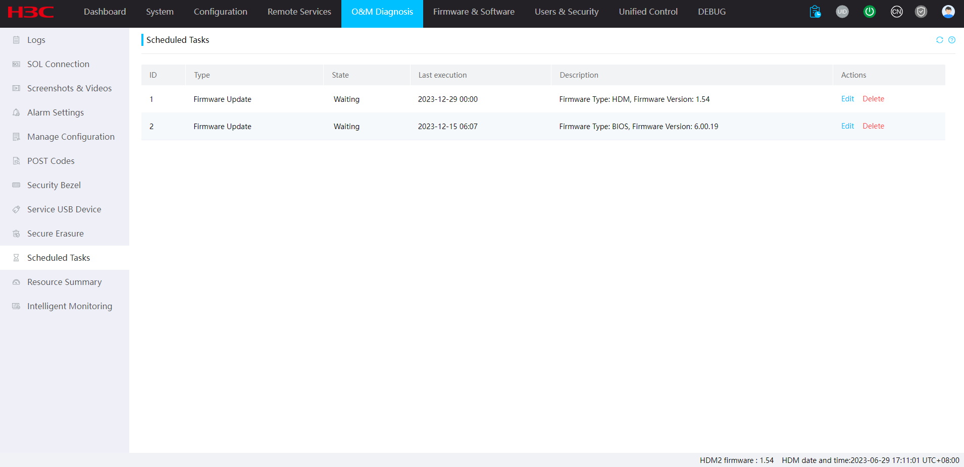
3. View all scheduled task information.
4. To modify a scheduled task, click Edit in the Actions column.
5. To delete a scheduled task, click Delete in the Actions column.
Parameters
· Type: Type of the scheduled task.
· State: State of the scheduled task. Options include Waiting, Executed, and Abnormal.
· Last execution: Last execution time for the scheduled task.
· Description: Detailed information for the scheduled task, including the firmware type and version.
Resource summary
Resource summary
Perform this task to set the alarm thresholds for processor, memory, and drive usage and view information about resource usage and performance monitoring. When the resource usage exceeds an alarm threshold, an alarm occurs. When the resource usage recovers to normal, an alarm is cleared.
Restrictions and guidelines
To use this feature, you must install and run FIST SMS in the operating system of the server. For more information, see the FIST SMS user guide for the server.
The system generates a log entry when an alarm occurs or is cleared. You can view the alarms in the event log.
Restoring HDM factory defaults clears all chart statistics.
Procedure
1. On the top navigation bar, click O&M Diagnosis.
2. In the left navigation pane, select Resource Summary, as shown in Figure 108.
3. If FIST SMS is absent, you can only view memory usage and CPU usage.
4. If FIST SMS is present, you can perform the following operations:
¡ Click Advanced Settings. Set the alarm thresholds for processor usage, memory usage, and drive usage, and then click OK, as shown in Figure 109.
¡ View resource usage and resource information historical trends, as shown in Figure 110.
Figure 108 Viewing resource summary

Figure 109 Setting the alarm thresholds
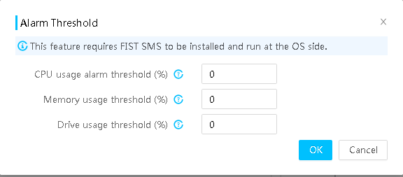
Figure 110 Viewing resource usage information
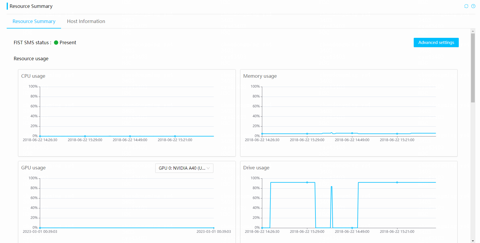
Parameters
Resource usage
· Drive usage threshold: Proportion of used drive space to the total size of the partition, drive partition directory, used space, and total partition space.
Drive performance info
· Low-performance drives (ms): Displays the drive load factor trend. If the load factor values of a drive exceed 1000 in five consecutive intervals, the drive is a low-performance drive.
· Drive read and write frequency (operations/s): Displays the read and write frequency trend of drive partitions.
Monitored performance
· NFS client read/write speed (kB/s): Displays the trend of NFS client read/write speed.
· NFS server read/write speed (kB/s): Displays the trend of NFS server read/write speed.
· System load: Measures the calculation amount processed by the system over a time period.
· Network throughput (Mbps): Displays the receive/send rate trend of the network.
Host information
Perform this task to view host running information, host-related information, process of the previous host startup, and process of the current host startup.
Procedure
1. On the top navigation bar, click O&M Diagnosis.
2. In the left navigation pane, select Resource Summary.
3. Click the Host Info tab to view host information.
4. To view information about a startup stage, click the expand icon for the stage in the process chart. Information displayed includes time consumption, stage start and end time, and information changes.
Figure 111 Viewing host information
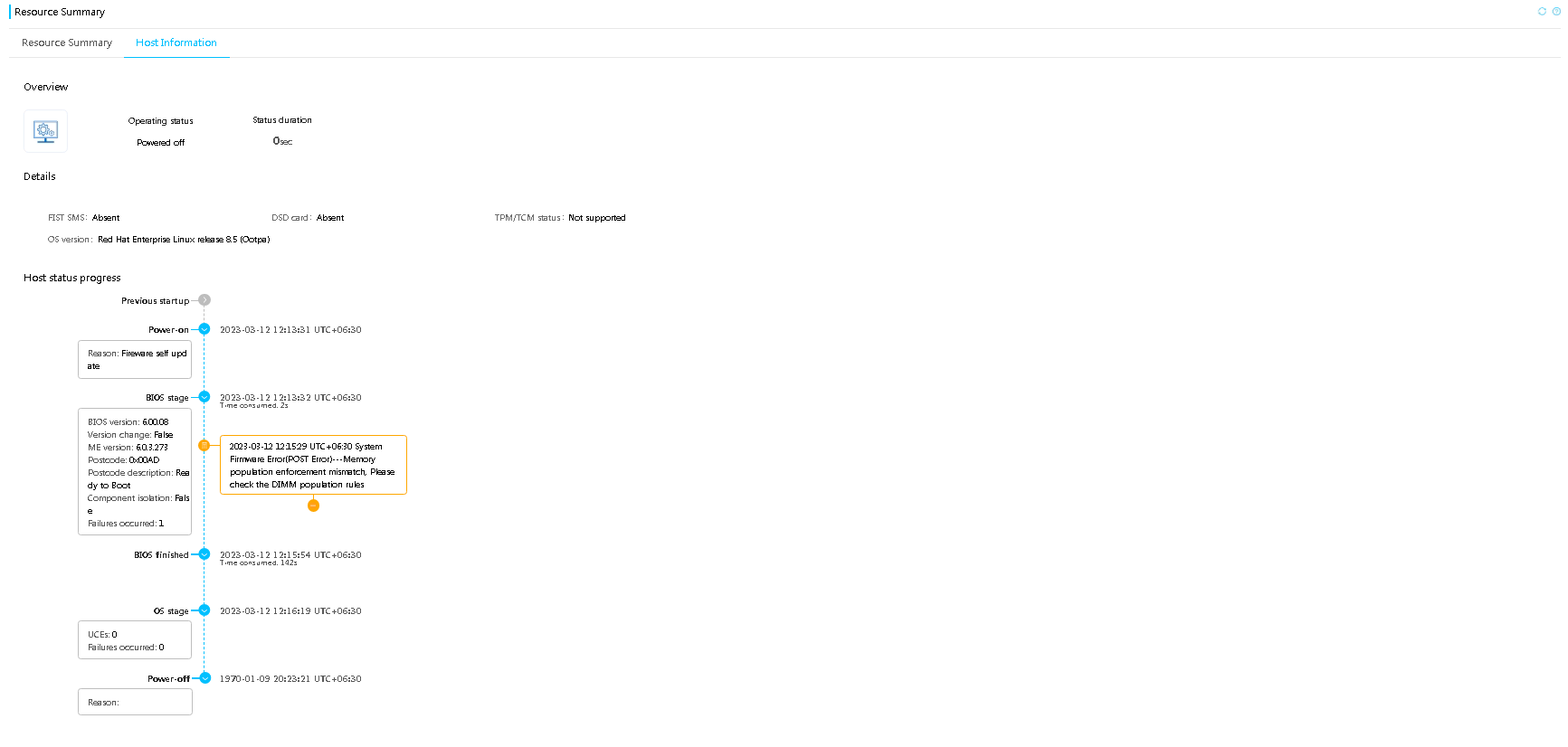
Figure 112 Viewing host stage information
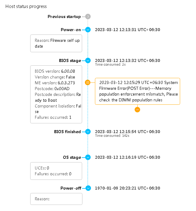
Parameters
· Previous startup: Process of the previous startup.
· Power-on: Stage from host power-on to BIOS startup.
¡Reason: Reason that causes the host to restart.
· BIOS stage: BIOS startup stage.
¡BIOS version: Current BIOS version number.
¡Version change: Whether the BIOS version is changed.
¡Postcode: Postcode for the startup.
¡Postcode description: Description of a postcode, which can be used to identify the BIOS running state and error information.
¡Component isolation: Whether a host-related component is blocked.
¡Failures occurred: Number of BIOS failures of the major or a higher level.
· BIOS finished: BIOS finish stage.
· OS stage: Stage from BIOS finish to system operation.
¡UCEs: Number of uncorrectable errors occurred on CPUs, PCIe modules, and memory.
¡Failures occurred: Number of host failures of the major or a higher level.
· Power-off: Host cold restart or power-off stage.
¡Reason: Reason that causes the host to be powered off.
Restrictions and guidelines
· If the host is hot restarted through software, the host startup process will not be recorded as a previous startup process.
· The BIOS stage can display up to 10 failure log entries of the major or a higher level.
Intelligent monitoring
Memory intelligent alarm
This feature allows users to view memory repair records. With memory intelligent alarm report enabled, the system reports SEL logs when hardware risks are detected for memory. With DIMM isolation enabled in the OS, the system can deny access to an error memory page.
The memory intelligent alarm feature requires licenses. For more information about licenses, see "License management."
Restrictions and guidelines
· DIMM isolation in the OS is available only for servers installed with Intel processors.
· The data is for illustration only. To use features on the page, a license is required.
Procedure
1. On the top navigation bar, click O&M Diagnosis.
2. In the left navigation pane, select Intelligent Monitoring.
Figure 113 Intelligent Monitoring
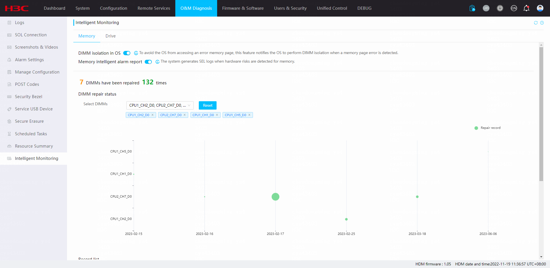
3. (Optional.) Enable DIMM isolation in the OS. By default, DIMM isolation in the OS is disabled.
4. (Optional.) Enable memory intelligent alarm report. By default, intelligent memory alarm report is disabled.
5. (Optional.) To hide the repair record marks in the graph, click Repair record. By default, the repair record marks are displayed. The larger a mark, the more the repair times of the DIMM in the slot at the corresponding time.
6. To display repair records of DIMMs in specific slots, select the slots from the Select DIMMs field. To select all DIMMs in the repair records, click Reset.
Figure 114 Select DIMMs
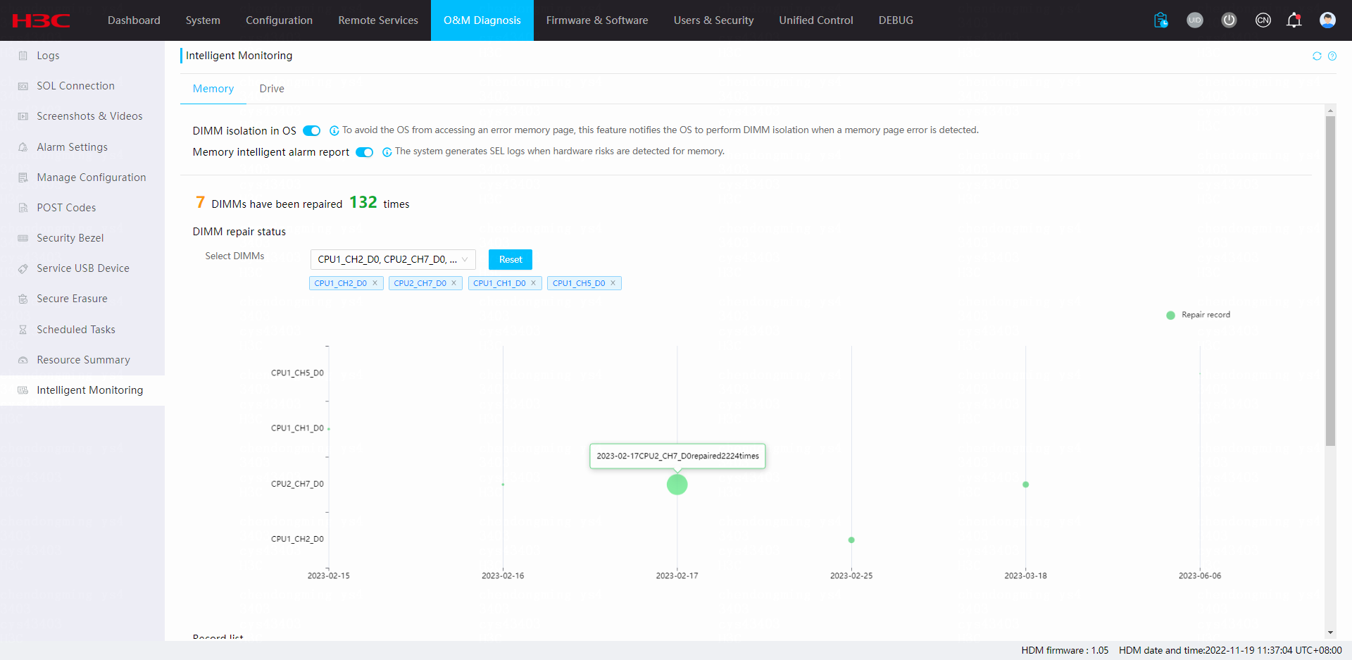
7. To view the most recent repair records, click Displays the most recent 40 records. The system displays only the most recent 40 records. To view repair records during the memory lifetime, click Displays repair records during the life cycle.
Figure 115 Displays the most recent 40 records
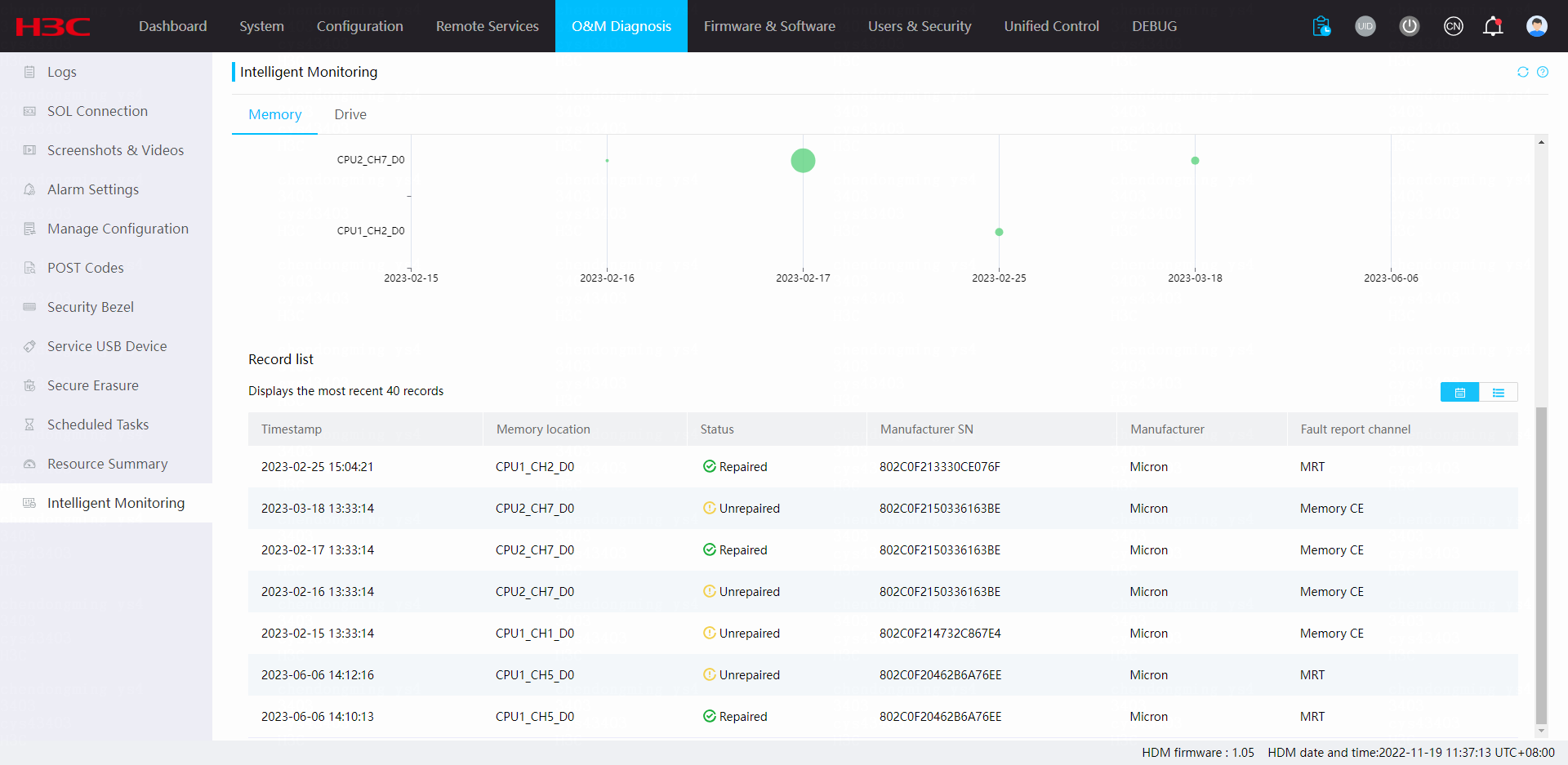
Parameters
· Displays the most recent 40 records: Displays the most recent 40 repair records of the selected DIMMs.
¡ Timestamp: Time at which the DIMM was repaired.
¡ Memory location: DIMM slot.
¡ Status: Repaired status of the DIMM.
¡ Manufacturer SN: Unique product code assigned by the manufacturer. This field displays N/A if the system fails to obtain the serial number.
¡ Manufacturer: Manufacturers of the DIMM.
¡ Fault report channel: Memory repair method. Options include Patrol Scrub, Memory CE, On-Die-ECC, Intel® Memory Resilience Technology, ADDDC, and PPR. The repair method is selected by the system automatically.
· Displays repair records during the life cycle: Displays all repair records of the selected DIMMs during its lifetime.
¡ Memory location: DIMM slot.
¡ Manufacturer SN: Unique product code assigned by the manufacturer. This field displays N/A if the system fails to obtain the serial number.
¡ Manufacturer: Manufacturers of the DIMM.
¡ History repairs: Total number of repairs of the DIMM.
¡ Last repaired at: Most recent time at which the DIMM was repaired.
Drive health
Perform this task to view health statistics of selected drives and make predictions on health indicators of some drives.
Procedure
1. On the top navigation bar, click O&M Diagnosis.
Figure 116 O&M Diagnosis
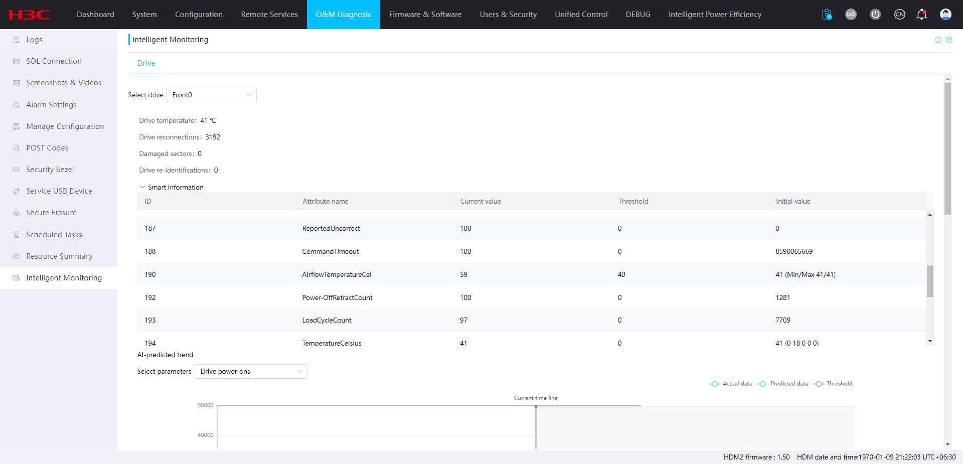
2. In the left navigation pane, select Intelligent Monitoring.
3. (Optional.) In the Select drive area, select a drive slot to view the drive information.
Figure 117 Select drive
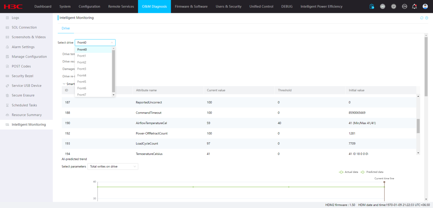
4. (Optional.) In the Select parameters area of the AI-predicted trend section, select health indicators to view the actual data and predicted data of the selected indicator.
Figure 118 AI-predicted trend
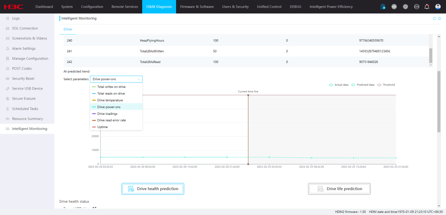
Restrictions and guidelines
· The SMART information of SAS HDDs does not contain IDs and initial values.
· The AI-predicted trend section can display history statistics for a maximum of 90 days and predicted statistics for a maximum of one day.
· The system stops updating the AI-predicted trend once the server is powered off. The trend will be updated after the server is powered on.
Parameters
· Select drive: Select a drive slot.
· Drive temperature: Temperature of the drive in the selected drive slot.
· Drive reconnections: Number of starts and stops of the drive spindle motor in the selected drive slot.
· Damaged sectors: Number of drive sectors that cannot be accessed or written in the selected drive slot.
· Drive re-identifications: Number of loadings or unloadings of the drive magnetic head in the selected slot.
· Smart information: Information about drive status detection and alarming.
¡ ID: Attribute ID of the SATA HDD SMART information.
¡ Attribute name—Attribute name that corresponds to the ID of the SATA HDD or SAS HDD SMART information.
¡ Current value—Result calculated based on the initial value. If the current value is close to the threshold, the drive health status decreases.
¡ Threshold—Threshold used to identify whether the drive is healthy.
¡ Initial value—SMART information value detected in real time during SATA HDD operation.
Drive health prediction
Perform this task to view health states and repair records of drives.
Procedure
1. On the top navigation bar, click O&M Diagnosis.
2. In the left navigation pane, select Intelligent Monitoring.
3. Click Drive health prediction. The system displays health status and repair records for drives.
Figure 119 Drive health prediction
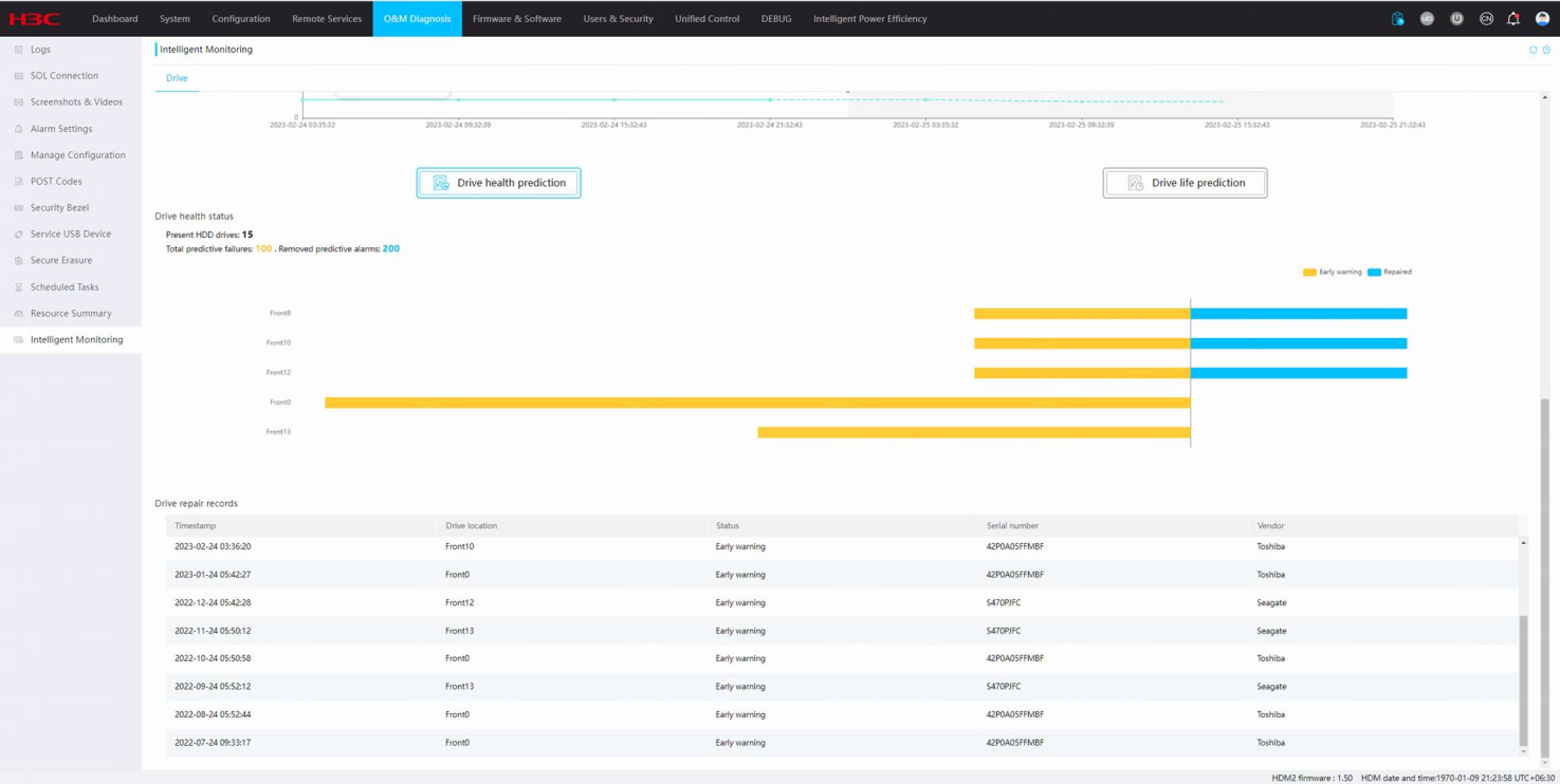
Restrictions and guidelines
· The Drive health prediction page can display a maximum of 1000 drive repair records.
· Drive health prediction supports only HDDs.
Parameters
· Drive repair records: Displays related records for drive predictive failures and failure repairs.
¡ Timestamp: Time at which the drive predictive failure occurs or the failure is repaired.
¡ Drive location: Drive slot information.
¡ Status: Drive health status.
- Early warning—A potential drive failure might exist or a drive failure has occurred.
- Repaired—Drive failures are repaired.
¡ Serial number: Unique identifier of the drive.
¡ Vendor: Vendor of the drive.
Drive life prediction
This feature provides drive life information and you can predict remaining life of drives based on the related information..
Restrictions and guidelines
Drive life prediction supports only SATA HDDs.
Procedure
1. On the top navigation bar, click O&M Diagnosis.
2. In the left navigation pane, select Intelligent Monitoring.
3. Click Drive life prediction. View read operation counts, write operation counts, and total uptime of drives.
Figure 120 Drive life prediction
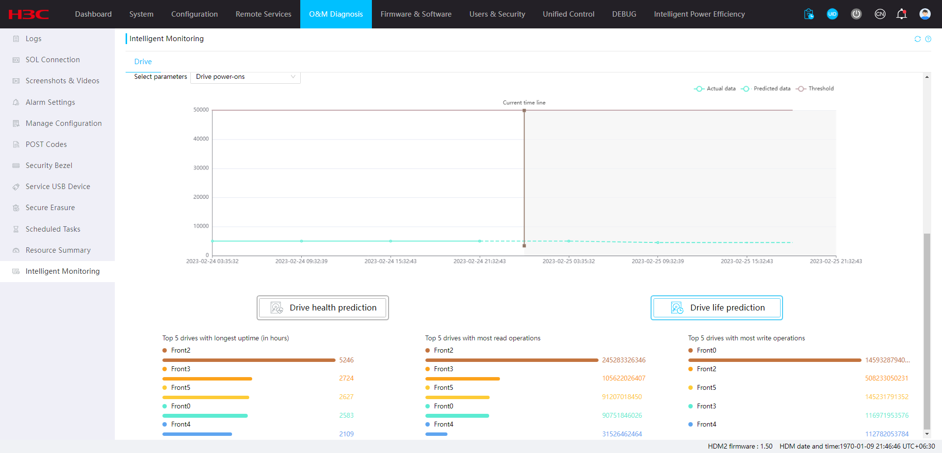
Parameters
· Top 5 drives with longest uptime (in hours): Top 5 HDDs that have the longest uptime.
· Top 5 drives with most read operations: Top 5 HDDs that have the most read operations.
· Top 5 drives with most write operations: Top 5 HDDs that have the most write operations.
Drive capacity prediction
This feature allows you to monitor the capacity of drive partitions. With the intelligent alarm report function enabled, you will receive warnings for any risks associated with the capacity of your drive partitions. You can also set up the time for drive capacity prediction and the alarm threshold, and view corresponding predictive curves.
|
|
IMPORTANT: To use this feature, install and run FIST SMS in the operating system. For more information, see H3C Servers FIST SMS User Guide. |
Procedure
1. On the top navigation bar, click O&M Diagnosis.
2. In the left navigation pane, select Intelligent Monitoring.
No data is displayed if FIST SMS is not running. Please install and run FIST SMS first.
Figure 121 Drive capacity prediction

3. Click Advanced Settings. Set the intelligent alarm state, intelligent alarm report state, prediction time, and alarm threshold.
Figure 122 Drive capacity advanced settings
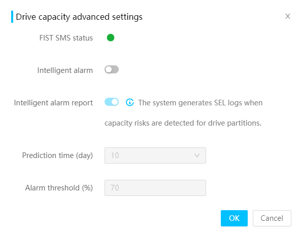
4. Click OK to save the settings.
5. Select drive partitions and view the capacity prediction curves for the partitions.
Figure 123 Capacity prediction curves for the partitions
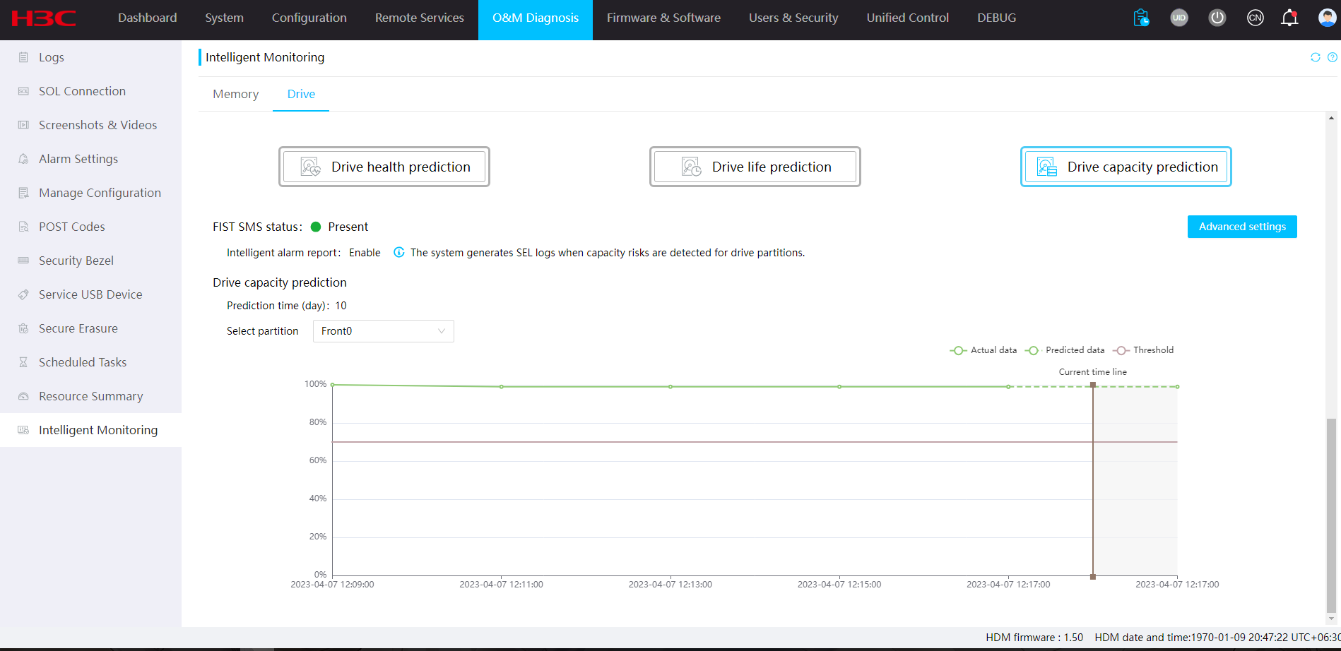
Parameters
· Intelligent alarm report: Enable the system to report alarms or alarm clearing events based on the alarm threshold and the predicted partition capacity usage. This feature is disabled by default.
· Prediction time: Specify the prediction time in days. By default, the value is 7 after you enable intelligent alarm. The maximum value is 21.
· Alarm threshold: Specify the partition capacity usage that can trigger an alarm.
Firmware and software
Firmware inventory
Perform this task to view and download firmware information for the server, including firmware name, device model, version, and location.
Procedure
1. On the top navigation bar, click Firmware & Software.
2. In the left navigation pane, select Firmware Inventory.
Figure 124 Viewing firmware inventory
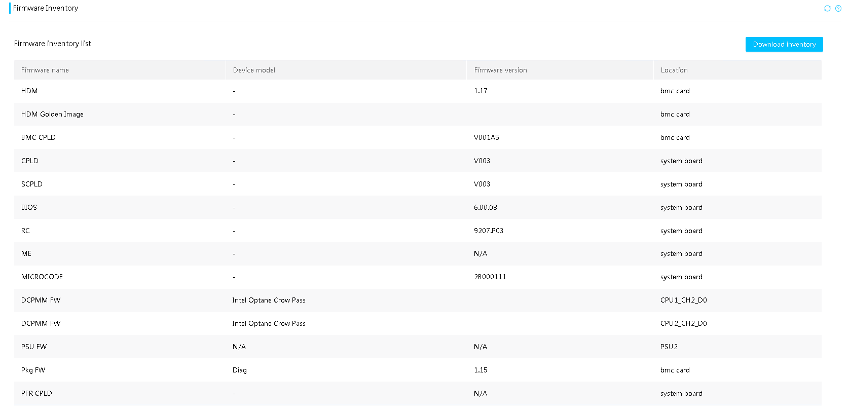
3. To download the firmware inventory to the local server, click Download inventory.
Parameters
· Firmware name: Name of the firmware. Options include HDM, BIOS, CPLD, ME, power supplies, LCD, and GPUFPGA. Firmware names of a component vary by product.
· Device model: Firmware vendor and component model information.
· Firmware version: External version information of the firmware.
· Location: Component or slot to which the firmware belongs. For example, iFIST belongs to the bmc card and CPLD belongs to the system board.
Installation package management
Procedure
1. On the top navigation bar, click Firmware & Software.
2. In the left navigation pane, select Installation Package Management.
Figure 125 Installation package management
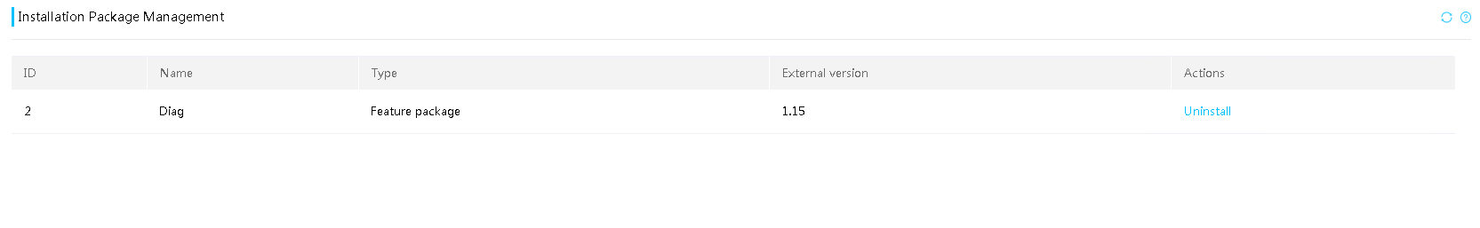
3. View the installation package information.
4. To remove an installation package, click Uninstall in the Actions column.
Parameters
· Name: Name of the installation package.
· Type: Type of the installation package.
¡ Patch package—Released for resolving issues for a specified HDM software version.
¡ Feature package—Released for adding new features to a specified HDM software version.
· External version: Version number of the installation package.
System software
Perform this task to view and download software information for the operating system, including position, name, version, update time.
Prerequisites
Before using this feature, install FIST SMS in the operating system. For more information, see FIST SMS user guide.
Procedure
1. On the top navigation bar, click Firmware & Software.
2. In the left navigation pane, select System Software.
You can view software inventory information for the OS, FIST SMS, and other software.
Figure 126 System software
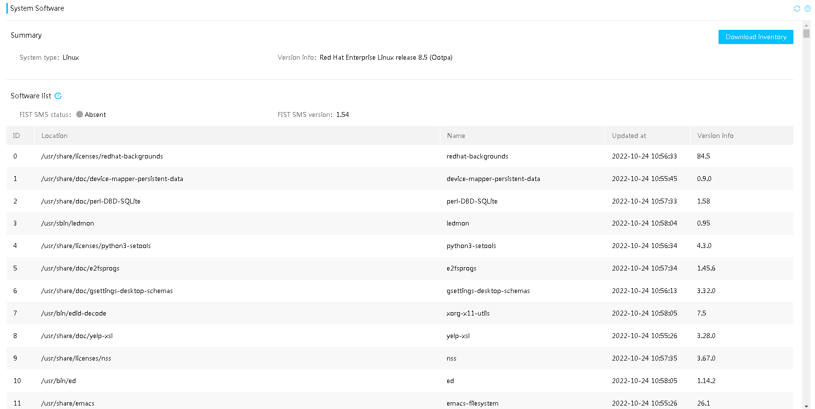
3. To download the software inventory to the local server, click Download inventory at the upper right corner.
Parameters
· System type: Type of the current operating system.
· Version info: Version information of the current operating system.
· FIST SMS status: Version information of FIST System Management Service (FIST SMS) installed in the operating system.
· Location: Installation directory for the software.
· Name: Name of the software.
· Updated at: Time at which the current software version updated.
· Version info: Version information of the software.
Firmware update
You can update the firmware of HDM, BIOS, CPLD, power supplies, and REPO. REPO firmware includes storage controller firmware, network adapter firmware, and drive firmware. Table 14 shows server models and the firmware types that they support.
Table 14 Server models and supported firmware types
|
Model |
Firmware type |
|
· R4700 G6 · R4900 G6 |
· HDM · BIOS · CPLD1 · CPLD2 · BPCPLD · PSU · PFRCPLD · BMCCPLD · Storage controller components · Netowrk adapter components · Drive components |
|
R4950 G6 |
· HDM · BIOS · CPLD1 · CPLD2 · BPCPLD · PSU · BMCCPLD · Storage controller components · Netowrk adapter components · Drive components |
Firmware update restrictions and guidelines
To ensure a successful firmware update, follow these restrictions and guidelines during the update:
· To avoid HDM or operating system errors, do not perform power actions on the server during the update.
· Do not refresh the HDM webpage during the update unless you are instructed to do so. Doing so will reset the update process.
Only one user can update firmware at a time. When you successfully start a firmware update, HDM automatically disables all other webpages and signs out all the other users. The signed-out users can sign in again only after the update is finished.
Firmware update might fail if the update image file does not contain a vendor signature or is corrupt. In this situation, obtain the desired firmware image file and try again.
During the firmware upgrade, do not refresh the upgrade page. Other login users cannot perform any operation except KVM access, SDS log downloading, and information query.
If CPLD update fails, the server will become unavailable. If the server cannot be accessed, contact Technical Support.
The following remote console menus are not available during the update:
· Keyboard menu in the KVM console.
· Send Keys and Hot Keys menus in the H5 KVM console.
Because of a limited HDM storage space, the uploaded image size cannot exceed the specified upper limit. To upload an image file with a large size, first delete the backup image file from the firmware library manually.
As a best practice, use the Local uploading method to upload firmware image.
Firmware update workflow
Figure 127 shows the firmware update workflow.
Figure 127 Firmware update workflow
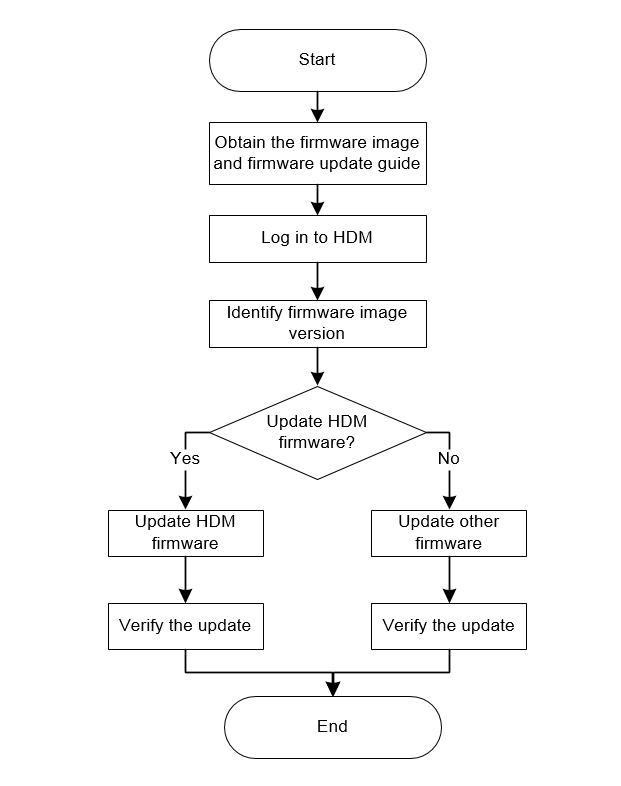
Prerequisites for firmware update
Before a firmware update, perform the following tasks:
1. Obtain the up-to-date server firmware image. Make sure the image matches the firmware type.
2. To avoid configuration loss caused by inadvertent mistakes, back up the configuration. You can export the HDM configuration for backup.
3. Make sure no user is updating firmware. You cannot update firmware if there is an ongoing firmware update.
Update the REPO for firmware update
Perform this task to update the REPO for the firmware update of HDM, BIOS, CPLD, power supplies, server components including storage controllers, network adapters, and drives.
Restrictions and guidelines
For the new firmware to take effect after REPO update, iFIST of the server is required. Make sure the iFIST version is compatible with the current HDM version. For information about the compatibility between HDM and iFIST, see HDM release notes or iFIST release notes.
At the first restart after REPO update from HDM, the server will automatically enter iFIST to make the new firmware of server components take effect. After the new firmware takes effect, the server automatically restarts again with boot options configured before the update.
Make sure the REPO image file to be uploaded does not exceed the upper limit as prompted, and the MD5 file does not exceed 1024 bytes.
During the process for the new firmware to take effect, do not restart the server or reconnect its power cords.
Methods for firmware to take effect after update vary by firmware type.
Table 15 Methods for firmware to take effect
|
Firmware type |
Method to take effect |
|
HDM |
Restart HDM. |
|
BIOS |
Restart or power on the server. |
|
BPCPLD |
Shut down the server or perform no action. |
|
· HDM installation package · PSU · Drive firmware |
The firmware takes effect automatically. |
|
· CPLD1 · CPLD2 · BMCCPLD · PFRCPLD · SWCPLD · DBCPLD · DeltaH800 · BRCPLD |
Restart CPLD or power off and power on the server. |
|
· Storage controller firmware · Network adapter firmware · Drive firmware |
Restart the server. |
For more restrictions and guidelines, see "Firmware update restrictions and guidelines."
Prerequisites
For information about how to download and use the REPO image file, see the REPO user guide for the server.
See "Prerequisites for firmware update."
Procedure
1. On the top navigation bar, click Firmware & Software.
2. In the left navigation pane, select Update Firmware.
3. In the Update Firmware section, click Update Firmware.
4. In the work pane, perform the following tasks:
a. Select an image upload method.
- If you select Local, select REPO as the firmware type. Browse to the update image file and select it. Then, browse to upload the MD5 file for the REPO as needed.
- If you select TFTP, enter the IP address of the interface used for image upload and enter the image name, which must include the suffix. Select REPO as the firmware type. Then, enter the name of the MD5 file for the REPO as needed, which must include the suffix.
b. To view the firmware inventory that can be updated by using REPO, click Download inventory.
Figure 128 Uploading REPO firmware image

5. Click Next to enter the page for confirming firmware information.
Figure 129 Confirming firmware information
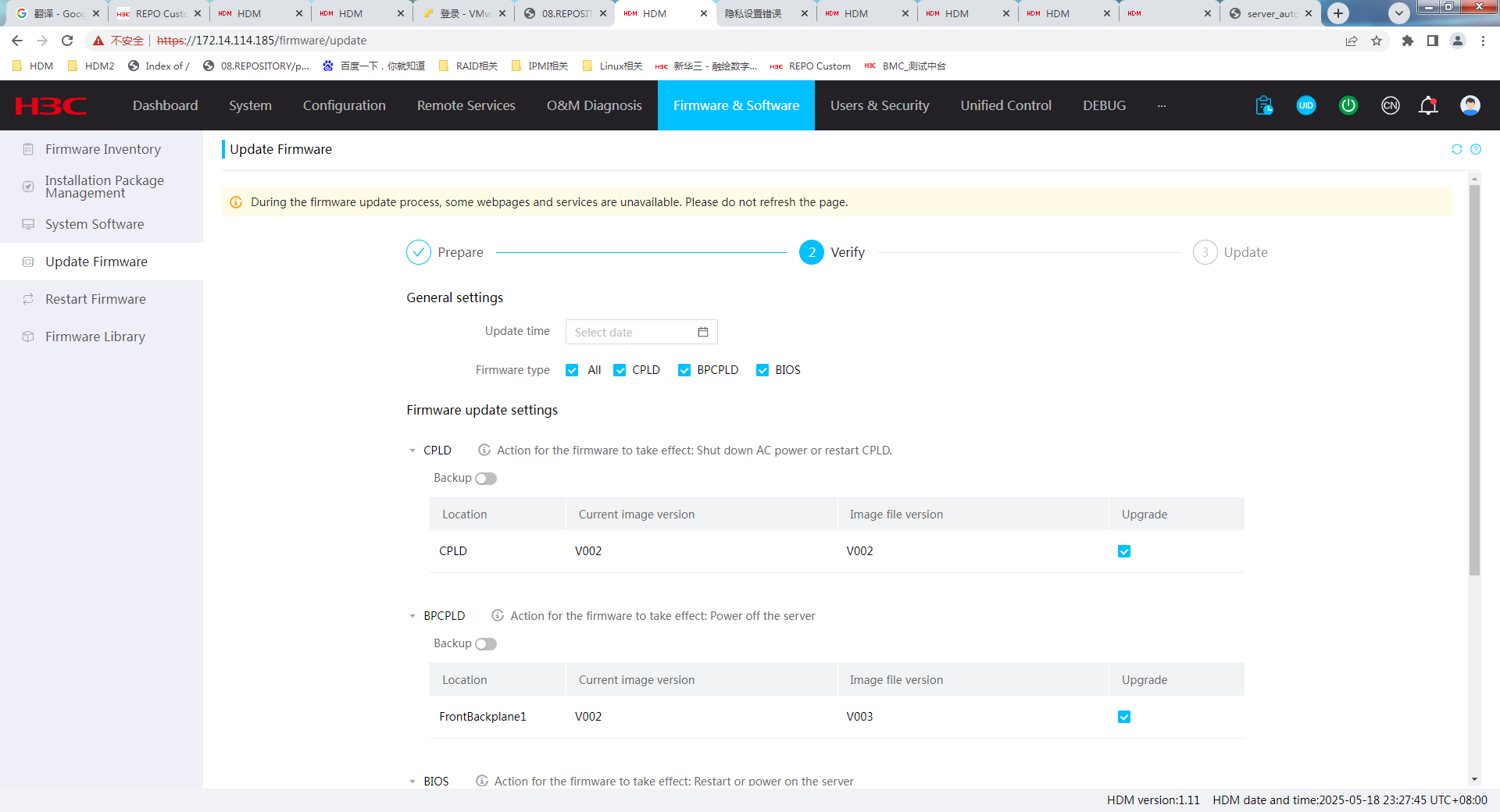
6. Set the update time as needed. After configuring, the system will establish a new scheduled task that is displayed on the Scheduled Tasks page.
7. Select one or multiple firmware to be updated.
8. View the firmware type, current version, firmware version of the upgrade file, and method to take effect.
9. Enable firmware backup as needed. After enabling, the firmware will be backed up into the firmware library.
10. When updating firmware for HDM, BIOS, and power supplies, configure respective firmware update settings:
¡ Select Enabled for Restore factory default as needed after HDM firmware update.
|
|
CAUTION: The Restore factory default option removes all user configured settings and restore factory defaults of the firmware when HDM starts up with the new firmware. When you select this option, make sure you understand its impact on the services. |
¡ Select whether to restore default BIOS settings after the update. The Restore factory default option is unavailable if you update only the ME firmware.
- To retain the user-configured BIOS settings, select Retain.
- To remove the user-configured BIOS settings and restore factory defaults, select Restore. If no factory defaults exist, the system restores the default settings.
- To remove the user-configured BIOS settings and restore default settings, select Forcedly restore. This option enables HDM to rewrite the BIOS flash and can be used when the BIOS is operating incorrectly and cannot be updated in any other ways. To avoid BIOS feature failures when using this feature, make sure the server is powered off.
The Forcedly restore option is available for BIOS firmware update only when the server is powered off.
¡ Select target components for firmware update of power supplies.
11. Verify that the firmware update configuration is correct, and then click Next.
The firmware update starts and the system displays the update progress.
Figure 130 Updating the firmware
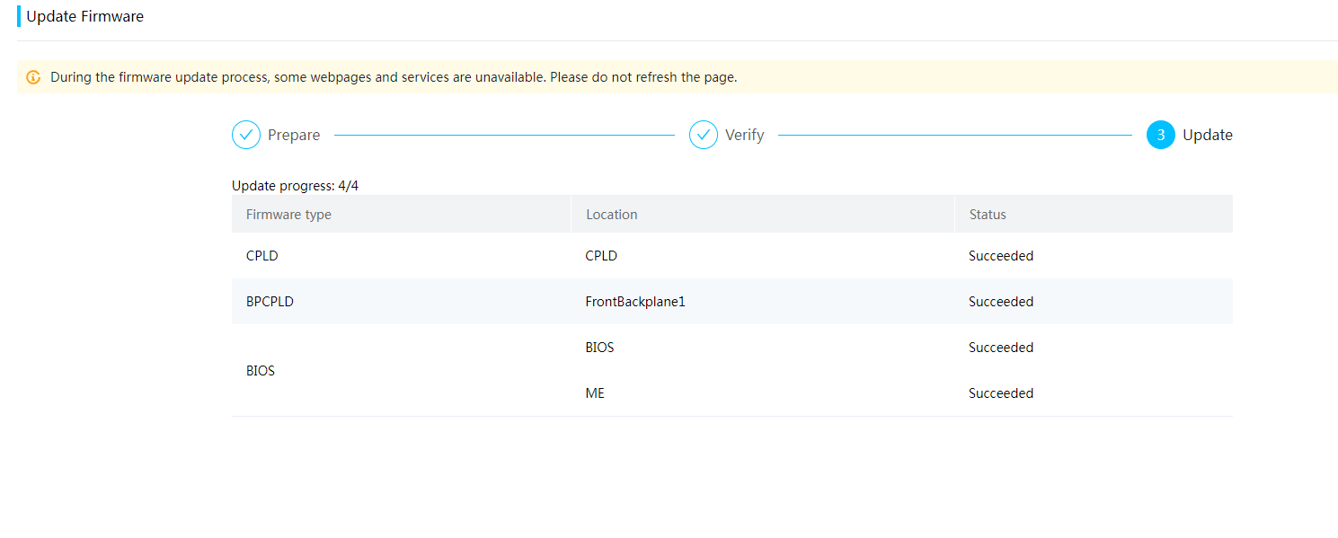
12. Access the Operation Log page from HDM to view the firmware update result.
Figure 131 Viewing the update result
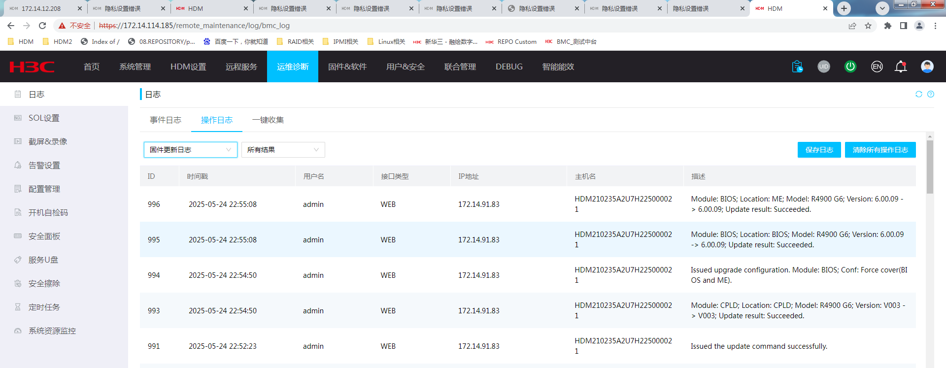
Update HDM firmware
HDM supports one primary firmware image and one backup firmware image, and it always runs the primary image.
To minimize the impact on HDM services, HDM uses the following procedure to update HDM firmware:
1. When you update HDM firmware, HDM replaces the backup firmware image with the uploaded update image.
2. When you restart HDM or perform a primary/backup switchover, HDM changes the roles of primary and backup HDM images. Then, HDM restarts with the update image, which is now the primary image.
Restrictions and guidelines
If the Restore factory default option is selected, you must use the default user account settings at the first sign-in to HDM after its firmware is updated.
Both HDM primary and backup images support update for multiple types of firmware, including HDM, the BIOS, CPLD, and power supplies.
When updating HDM firmware from the Web interface, the system only updates the firmware for the primary image.
Clearing the browser cache ensures the correct display of webpage contents after you re-sign in to HDM.
After you enable the PFR function, the updated HDM firmware will restart twice and the BIOS will also be restarted. The startup time of HDM and the BIOS will be slightly longer, which is normal. To avoid negative impact, make sure no running service operations are present.
For more restrictions and guidelines, see "Firmware update restrictions and guidelines."
Prerequisites
See "Prerequisites for firmware update."
Procedure
1. On the top navigation bar, click Firmware & Software.
2. In the left navigation pane, select Update Firmware.
3. In the work pane, perform the following tasks:
Select an image upload method.
- If you select Local, select HDM as the firmware type. Then, browse to the update image file and select it.
- If you select TFTP, enter the IP address of the interface used for file upload and enter the image name. Then, select HDM as the firmware type. The image name must include the suffix.
Figure 132 Selecting an image upload method

4. Click Next to access the page for confirming firmware information. Perform the following tasks:
a. Set the update time as needed. After setting, HDM will establish a new scheduled task that is displayed on the Schedule Tasks page.
b. Verify that the firmware type, current version of image in use, and image file version are correct.
c. Select Enabled for Restore factory default as needed after HDM firmware update.
|
|
CAUTION: The Restore factory default option removes all user configured settings and restore factory defaults of the firmware when HDM starts up with the new firmware. When you select this option, make sure you understand its impact on the services. |
d. Select the method to reboot the server after the update is complete.
You can have the server automatically restart immediately. Alternatively, you can choose Restart the Server Manually to manually restart the server.
e. Enable firmware backup as needed. After enabling, the firmware will be backed up into the firmware library.
Figure 133 Confirming firmware information
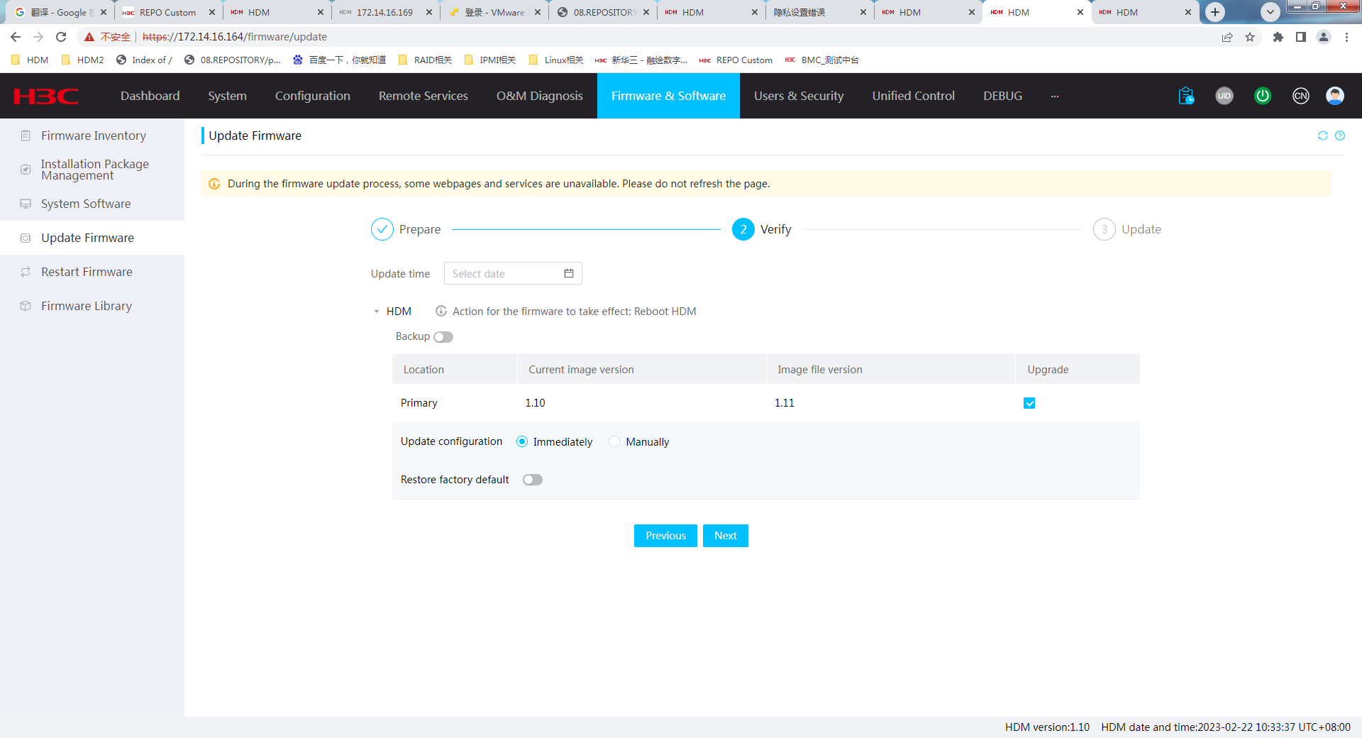
6. After update, restart HDM for the firmware to take effect.
¡ If you select to take effect immediately, HDM restarts automatically after the firmware update.
¡ If you select to take effect manually, you must restrt HDM manually for the new firmware to take effect.
Update HDM installation package
Perform this task to update the HDM installation package.
· Patch package—Released for resolving issues for a specified HDM software version.
· Feature package—Released for adding new features to a specified HDM software version.
Restrictions and guidelines
· You can use this feature to update the firmware only when the firmware version in the installation package is the same as the current HDM firmware version.
· After the HDM installation package update finishes, you can view installation package summary in "Installation Package Management."
Procedure
1. On the top navigation bar, click Firmware & Software.
2. In the left navigation pane, select Update Firmware.
Figure 134 Update firmware

3. In the work pane, select an image upload method.
¡ If you select Local, select HDM as the firmware type. Then, browse to the update image file and select it.
¡ If you select TFTP, enter the IP address of the interface used for file upload and enter the image name. Then, select HDM as the firmware type.
4. Click Next to confirm the installation page information.
Figure 135 Confirming the installation page information
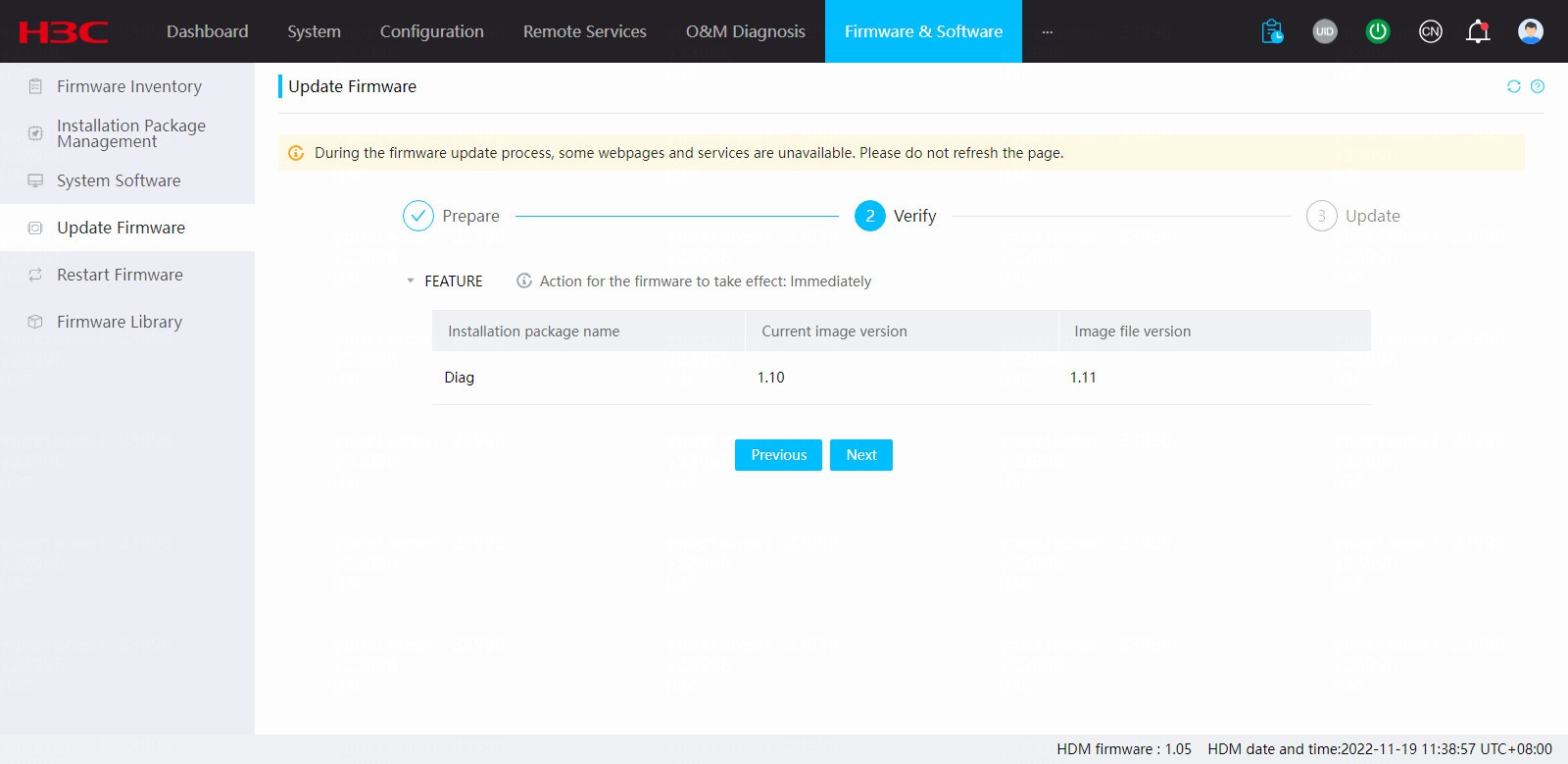
5. Click Next. The installation package update starts.
The new installation package takes effect automatically after update.
Figure 136 Viewing version information
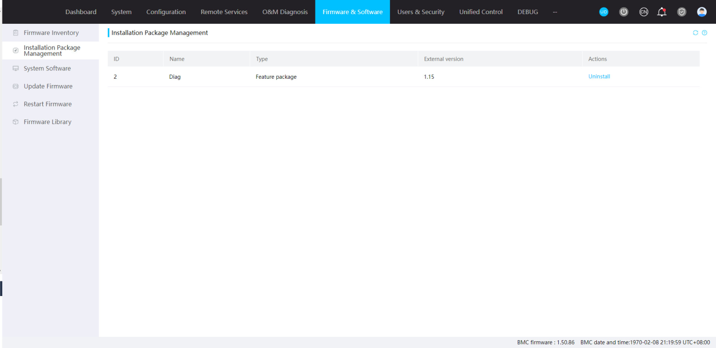
Update BIOS firmware
HDM Web interface supports the following method for BIOS firmware update:
· Uploading the BIOS firmware—The method can update the BIOS and ME firmware simultaneously. You can retain the user-configured BIOS settings, remove the user-configured BIOS settings and restore factory defaults, or remove the user-configured BIOS settings and restore the default settings. After the update, you must restart the server for the new firmware to take effect.
Restrictions and guidelines
To avoid update errors, make sure power supply redundancy is normal before the update.
If the Restore or Forcedly restore option is selected, the boot mode in the BIOS changes to the default after the update.
After an update, the server must restart for the new firmware to take effect. To avoid BIOS errors, do not perform BIOS update again or restart HDM during the restart.
For a server installed with Intel processors, do not perform graceful power-off from HDM to restart the server after you update the BIOS with the Forcedly restore option specified. If you perform graceful power-off, ME exceptions might occur.
To avoid BIOS errors, make sure the system has entered the boot options before you update the firmware if the server is up.
All user-configured BIOS settings will get lost if you downgrade the BIOS firmware.
After BIOS firmware is updated, HDM can display the BIOS version correctly only when the server is restarted and the POST stage is finished.
Configurations for storage controllers and network adapters are saved on the modules themselves, which have nothing to do with Rstore Factory Defaults.
After you enable the PFR function, only Forcedly restore is supported. Back up the user configuration in advance as a best practice. HDM will restart after the update. The startup time of HDM and the BIOS will be slightly longer, which is normal.
For more restrictions and guidelines, see "Firmware update restrictions and guidelines."
Prerequisites
See "Prerequisites for firmware update."
Procedure
1. On the top navigation bar, click Firmware & Software.
2. In the left navigation pane, select Update Firmware.
3. In the Update Firmware section, click Update Firmware.
The firmware image file upload page as shown in Figure 137 opens.
Figure 137 Uploading firmware image

4. In the work pane, perform the following tasks:
a. Select an image upload method.
- If you select Local, select BIOS as the firmware type. Then, browse to the update image file and select it.
- If you select TFTP, enter the IP address of the interface used for image upload and enter the image name. Then, select BIOS as the firmware type. The image name must include the suffix.
5. Click Next to access the page for confirming firmware information. Perform the following tasks:
a. Set the update time as needed. After setting, HMD will establish a new scheduled task that is displayed on the Schedule Tasks page.
b. Verify that the firmware type, current version of image in use, and image file version are correct.
c. Select components to be updated. This task is available only for servers installed with Intel processors.
You cannot select only ME when the server is up.
d. Specify Immediately or Manually for the update configuration. This field is available only when the server is up.
e. Select whether to restore factory defaults after the update.
The Restore factory default option is available only when you update the BIOS firmware by uploading the BIOS firmware. When you update only the ME firmware, the Restore factory default option is not supported.
- To retain the user-configured BIOS settings, select Retain.
- To remove the user-configured BIOS settings and restore factory defaults, select Restore. If no factory defaults exist, the system restores the default settings.
- To remove the user-configured BIOS settings and restore default settings, select Forcedly restore. This option enables HDM to rewrite the BIOS flash and can be used when the BIOS is operating incorrectly and cannot be updated in any other ways.
The Forcedly restore option is available for BIOS firmware update only when the server is powered off.
f. Enable firmware backup as needed. After enabling, the firmware will be backed up into the firmware library.
Figure 138 Confirming firmware information
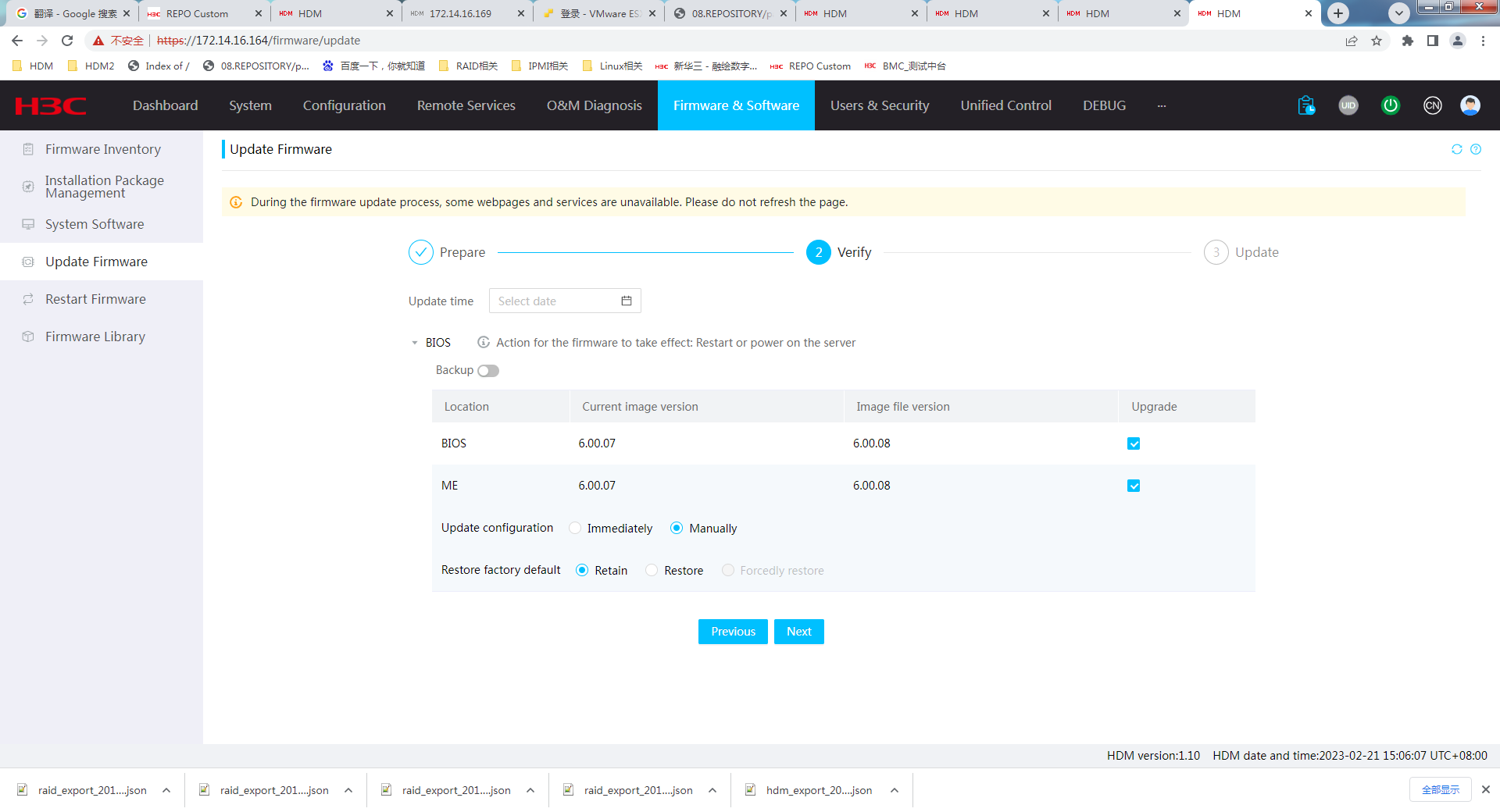
6. Click Next.
7. After update, restart the server for the BIOS firmware to take effect.
Update CPLD firmware
Perform this task to update the following types of CPLD firmware: CPLD1, CPLD2, PFRCPLD, BMCCPLD, SWCPLD, DBCPLD, and BRCPLD.
Restrictions and guidelines
The supported CPLD firmware types vary by device model.
If CPLD firmware update fails, the server cannot operate correctly.
Update of the PFRCPLD firmware is supported only when the PFR function is enabled. The update also restarts HDM and the BIOS, which is normal. To avoid negative impact, make sure no running service operations are present.
For more restrictions and guidelines, see "Firmware update restrictions and guidelines."
Prerequisites
See "Prerequisites for firmware update."
Procedure
1. On the top navigation bar, click Firmware & Software.
2. In the left navigation pane, select Update Firmware.
3. In the Update Firmware section, click Update Firmware.
The firmware image file upload page as shown in Figure 139 opens.
Figure 139 Uploading firmware image

4. In the work pane, perform the following tasks:
Select an image upload method.
- If you select Local, select CPLD as the firmware type. Then, browse to the update image file and select it.
- If you select TFTP, enter the IP address of the interface used for image upload and enter the image name. Then, select CPLD as the firmware type. The image name must include the suffix.
5. Click Next to access the page for confirming firmware information. Perform the following tasks:
a. Set the update time as needed. After setting, HDM will establish a new scheduled task that is displayed on the Schedule Tasks page.
b. Verify that the firmware type, current version of image in use, and image file version are correct.
c. Enable firmware backup as needed. After enabling, the firmware will be backed up into the firmware library.
Figure 140 Verifying firmware information
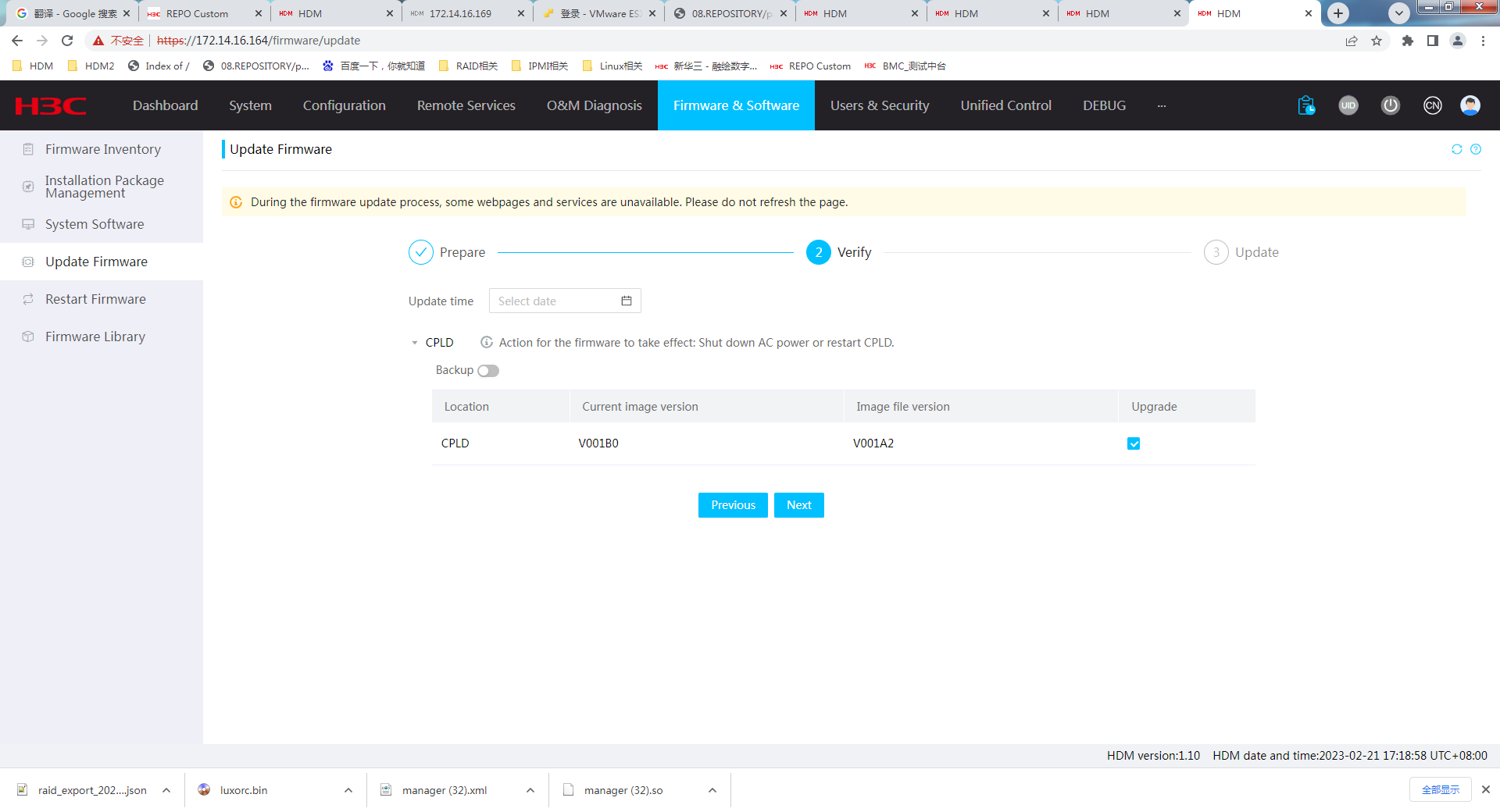
6. Click Next.
The firmware update starts and the system displays the update progress.
7. After the update is complete, access the Restart firmware page, and then click Restart CPLD for the firmware to take effect.
Update drive backplane firmware
Restrictions and guidelines
An update operation updates only drive backplanes supported by the uploaded BPCPLD image file.
You can update the BPCPLD firmware when the server is powered on or off. To avoid update failures, do not perform power actions or reconnect the power cords during the update.
If the update fails for a drive backplane, the system will try again. A maximum of three update attempts are allowed for each drive backplane.
You can try to start a new update after the current update fails. If multiple updates fail, contact the technical support to use a different method to update the firmware.
For more restrictions and guidelines, see "Firmware update restrictions and guidelines."
Prerequisites
See "Prerequisites for firmware update."
Procedure
1. On the top navigation bar, click Firmware & Software.
2. In the left navigation pane, select Update Firmware.
3. In the Update Firmware section, click Update Firmware.
The firmware image file upload page as shown in Figure 141 opens.
Figure 141 Uploading firmware image

4. In the work pane, perform the following tasks:
Select an image upload method. As a best practice, use the Local upload method.
- If you select Local, select BPCPLD as the firmware type. Then, browse to the update image file and select it.
- If you select TFTP, enter the IP address of the interface used for image upload and enter the image name. Then, select BPCPLD as the firmware type. The image name must include the suffix.
5. Click Next to access the page for confirming firmware information. Perform the following tasks:
a. Set the update time as needed. After setting, HDM will establish a new scheduled task that is displayed on the Schedule Tasks page.
b. Verify that the firmware type, current version of image in use, and image file version are correct.
c. Enable firmware backup as needed. After enabling, the firmware will be backed up into the firmware library.
Figure 142 Verifying firmware information
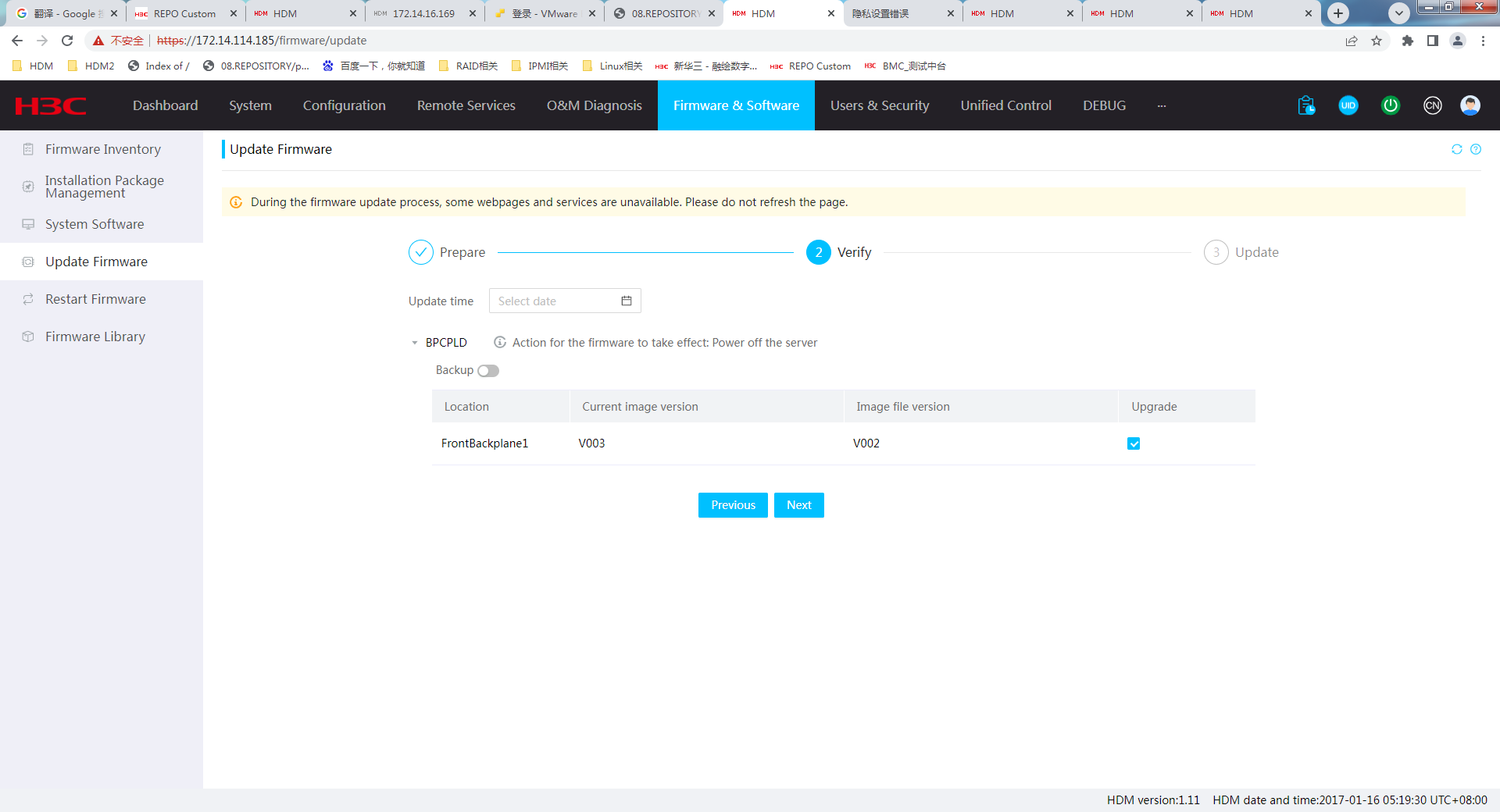
6. Click Next. The firmware update starts.
After the update finishes, if the server is powered on, the new firmware takes effect after you power off the server. If the server is powered off, the new firmware takes effect immediately.
Update power supply firmware
Restrictions and guidelines
The system updates the firmware only for power supplies using the same model defined in the image file and updates the power supplies one by one. The power supply that is being updated cannot supply power to the server. Make sure a minimum of one power supply is present and the power supply can provide power to the system board during the update process.
Before the update, make sure the present power supplies are operating correctly.
If the system supports power supply grouping, make sure power supplies in the same group have the same model.
Power supply firmware supports the following update methods:
· Immediate update—Start immediately once the new firmware image version is verified.
To avoid power supply errors, do not power on or power off the server or disconnect any power supply during the update.
· Update after server power-off—Start nine seconds after the server is powered off.
To avoid power supply errors, do not power on the server or disconnect any power supply during the update.
The firmware update method is determined by the image file. Before the update, contact Technical Support to identify the update method.
The update process might take a long time.
If the update fails for a power supply, the power supply might fail to operate.
For more restrictions and guidelines, see "Firmware update restrictions and guidelines."
Prerequisites
See "Prerequisites for firmware update."
Procedure
1. On the top navigation bar, click Firmware & Software.
2. In the left navigation pane, select Update Firmware.
3. In the Update Firmware section, click Update Firmware.
The firmware image file upload page as shown in Figure 143 opens.
Figure 143 Uploading firmware image

4. In the work pane, perform the following tasks:
Select an image upload method.
- If you select Local, select PSU as the firmware type. Then, browse to the update image file and select it.
- If you select TFTP, enter the IP address of the interface used for image upload and enter the image name. Then, select PSU as the firmware type. The image name must include the suffix.
5. Click Next to access the page for confirming firmware information. Perform the following tasks:
a. Set the update time as needed. After setting, HDM will establish a new scheduled task that is displayed on the Schedule Tasks page.
b. Verify that the target power supply module, current version of image in use, and image file version are correct.
c. Enable firmware backup as needed. After enabling, the firmware will be backed up into the firmware library.
Figure 144 Verifying firmware information
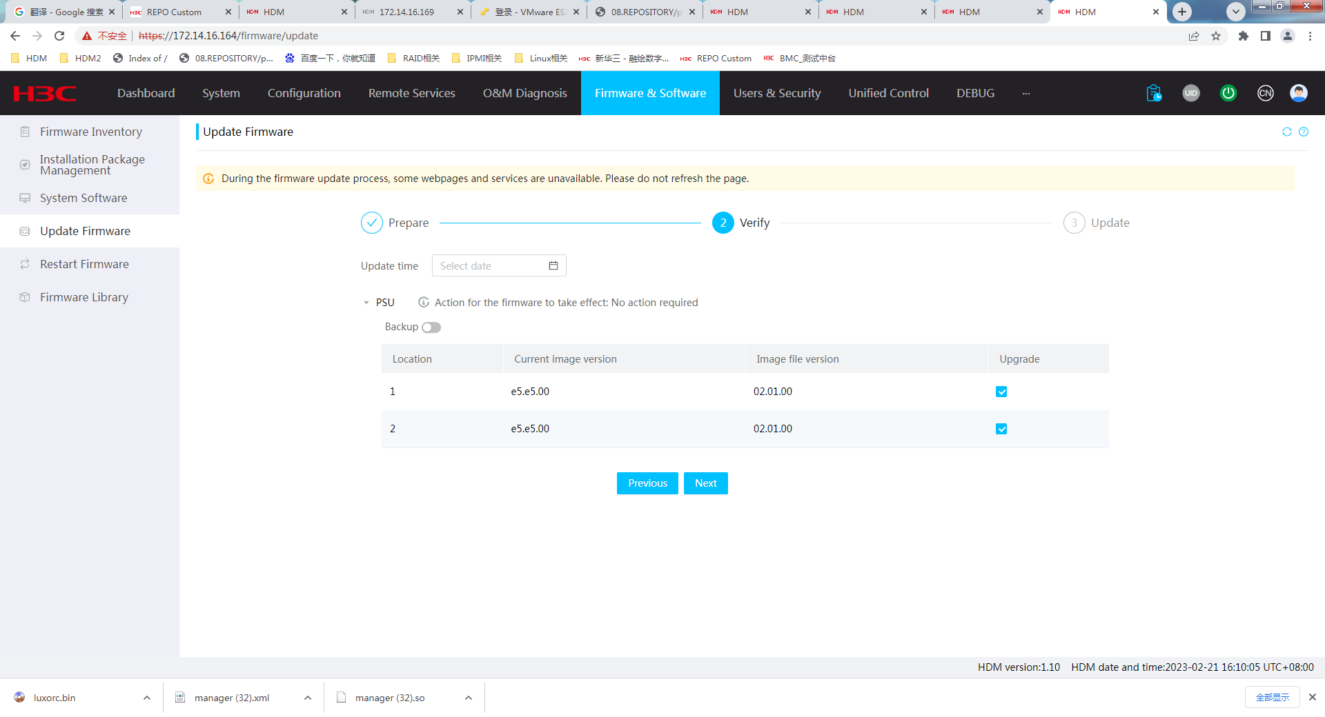
6. Click Next.
The server starts the update immediately or after the server is powered off depending on the update method of the new firmware image.
To view the update result for each power supply, go to Operation Log.
The new firmware takes effect automatically after the update finishes.
Update GPUCPLD firmware
Perform this task to update the CPLD firmware for GPUs.
Restrictions and guidelines
This feature is available only for some servers and specific GPUs. If multiple GPUs are present, the operation updates only GPUs supported by the uploaded GPUCPLD image.
If the update fails for a GPU, the system retries. The system allows a maximum of two retries.
The BIOS will restart multiple times during the update process.
This feature is available only when the server is powered on. During the update process, do not power off or remove power from the server. If you do so, the update might fail or GPUs might fail to be identified.
For more restrictions and guidelines, see "Firmware update restrictions and guidelines."
Prerequisites
See "Prerequisites for firmware update."
Procedure
1. On the top navigation bar, click Firmware & Software.
2. In the left navigation pane, select Update Firmware.
3. In the Update Firmware section, click Update Firmware.
The firmware image file upload page as shown in Figure 145 opens.
Figure 145 Uploading firmware image
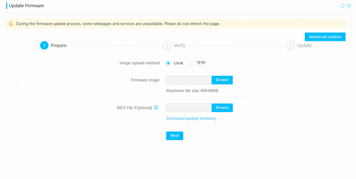
4. In the work pane, perform the following tasks:
a. Select an image upload method.
- If you select Local, select GPUCPLD as the firmware type. Then, browse to the update image file and select it.
- If you select TFTP, enter the IP address of the interface used for image upload and enter the image name. Then, select GPUCPLD as the firmware type. The image name must include the suffix.
5. Click Next to access the page for confirming firmware information. Perform the following tasks:
a. Set the update time as needed. After setting, HDM will establish a new scheduled task that is displayed on the Schedule Tasks page.
b. Select GPU to be updated. Verify that the GPU information for update, current version of image in use, and image file version are correct.
c. Enable firmware backup as needed. After enabling, the firmware will be backed up into the firmware library.
6. Click Next.
7. After the update, for the new firmware to take effect, power cycle the server with the power source reconnected.
Update GPUFPGA firmware
Perform this task to update the Field Programmable Gate Array (FPGA) firmware for GPUs.
Restrictions and guidelines
This feature is available only for specific GPUs. If multiple GPUs are present, the operation updates only GPUs supported by the uploaded GPUFPGA image.
If the update fails for a GPU, the system retries. The system allows a maximum of two retries.
This feature is available only when the server is powered on. During the update process, do not power off or remove power from the server. If you do so, the update might fail or GPUs might fail to be identified.
For more restrictions and guidelines, see "Firmware update restrictions and guidelines."
Prerequisites
See "Prerequisites for firmware update."
Procedure
1. On the top navigation bar, click Firmware & Software.
2. In the left navigation pane, select Update Firmware.
3. In the Update Firmware section, click Update Firmware.
The firmware image file upload page as shown in Figure 146 opens.
Figure 146 Uploading firmware image

4. In the work pane, perform the following tasks:
a. Select an image upload method.
- If you select Local, select GPUFPGA as the firmware type. Then, browse to the update image file and select it.
- If you select TFTP, enter the IP address of the interface used for image upload and enter the image name. Then, select GPUFPGA as the firmware type. The image name must include the suffix.
5. Click Next to access the page for confirming firmware information. Perform the following tasks:
a. Set the update time as needed. After setting, HDM will establish a new scheduled task that is displayed on the Schedule Tasks page.
b. Verify that the firmware type, GPU information, current version of image in use, and image file version are correct.
c. Enable firmware backup as needed. After enabling, the firmware will be backed up into the firmware library.
6. Click Next.
7. After the update, for the new firmware to take effect, power cycle the server.
Update GPUH800 firmware
Perform this task to update firmware for components on the Delta H800 module (firmware name GPUH800), including GPU, HMC, FPGA, NVSwitch, PCIe switch, and PCIe retimer.
Restrictions and guidelines
After the server is powered on, wait for the BIOS to complete a full startup before you perform update tasks for the GPUH800 firmware. If you fail to do so, the update might fail or components might fail to be identified.
This feature is available only when the server is powered on. During the update process, do not power off or remove power from the server. If you do so, the update might fail or components might fail to be identified.
For more restrictions and guidelines, see "Firmware update restrictions and guidelines."
Prerequisites
See "Prerequisites for firmware update."
Procedure
1. On the top navigation bar, click Firmware & Software.
2. In the left navigation pane, select Update Firmware.
3. In the Update Firmware section, click Update Firmware.
The firmware image file upload page as shown in Figure 147 opens.
Figure 147 Uploading firmware image

4. In the work pane, select an image upload method.
¡ If you select Local, browse to the update image file and select it.
¡ If you select TFTP, enter the IP address of the TFTP server and the image name. The image name must include the suffix. Make sure the address is the same as the value of the Server interfaces field in the tftpd tool.
5. Click Next to access the page for confirming firmware information. Perform the following tasks:
a. Set the update time as needed. After setting, HDM will establish a new scheduled task that is displayed on the Schedule Tasks page.
b. Verify the current image versions and update image versions for components. By default, all components of the module are selected for update.
c. Enable firmware backup as needed. After enabling, the firmware will be backed up into the firmware library.
6. Click Next.
7. After the update, for the new firmware to take effect, restart CPLD or power off and power on the server.
Update firmware for retimer on the BIREN GPU module
Perform this task to update firmware for PCIe retimer on the BIREN GPU module.
Restrictions and guidelines
After the server is powered on, wait for the BIOS to complete a full startup before you perform update tasks for the retimer firmware on the BIREN GPU module. If you fail to do so, the update might fail or components might fail to be identified.
This feature is available only when the server is powered on. During the update process, do not power off or remove power from the server. If you do so, the update might fail or components might fail to be identified.
Procedure
1. On the top navigation bar, click Firmware & Software.
2. In the left navigation pane, select Update Firmware.
The firmware image file upload page as shown in Figure 147 opens.
3. In the work pane, select an image upload method.
¡ If you select Local, browse to the update image file and select it.
¡ If you select TFTP, enter the IP address of the TFTP server and the image name. The image name must include the suffix. Make sure the address is the same as the value of the Server interfaces field in the tftpd tool.
4. Click Next to access the page for confirming firmware information. Perform the following tasks:
a. Set the update time as needed. After setting, HDM will establish a new scheduled task that is displayed on the Schedule Tasks page.
b. Verify the current image versions and update image versions for components. By default, all components of the module are selected for update.
c. Enable firmware backup as needed. After enabling, the firmware will be backed up into the firmware library.
5. Click Next.
6. After the update, the new firmware to take effect immediately.
Update firmware for storage controllers, network adapters, and drives
Restrictions and guidelines
When multiple components of different models are present, you can update firmware only for components whose firmware images are available for update.
You can update firmware for storage controllers, network adapters, and drives when the server is up and can update firmware for only network adapters when the server is down. To avoid update or component identification failures, do not power off the server or disconnect the power cord during firmware update for storage controllers, network adapters, and drives.
If the update fails for the firmware, the system retries. The system allows a maximum of two retries.
For more restrictions and guidelines, see "Firmware update restrictions and guidelines."
Prerequisites
Before updating, contact Technical Support to confirm the component information for firmware update.
Procedure
1. On the top navigation bar, click Firmware & Software.
2. In the left navigation pane, select Update Firmware.
The firmware image file upload page as shown in Figure 148 opens.
Figure 148 Uploading firmware image

3. In the work pane, perform the following tasks:
a. Select an image upload method.
- If you select Local, browse to the update image file and select it.
- If you select TFTP, enter the IP address of the interface used for image upload and enter the image name. The image name must include the suffix.
4. Click Next to access the page for confirming firmware information. Perform the following tasks:
a. Set the update time as needed. After setting, HDM will establish a new scheduled task that is displayed on the Schedule Tasks page.
b. Select the target components. Verify that the firmware information, current version of image in use, and image file version are correct.
c. Enable firmware backup as needed. After enabling, the firmware will be backed up into the firmware library.
Figure 149 Verifying firmware information
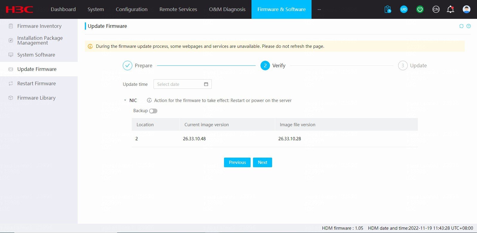
5. Click Next.
6. After the update, for the new firmware for storage controllers and network adapters to take effect, restart the server. The new firmware for drives will take effect automatically.
Advanced options
Perform this task to configure HDM firmware anomaly recovery, BIOS firmware anomaly recovery, and update task recovery after an unexpected restart.
Restrictions and guidelines
· When the system is running with the backup firmware, you cannot configure HDM firmware anomaly recovery.
· Besides state changes of configuration items on the Advanced options page, default setting restoration, factory default restoration, and HDM configuration import might also change the states of configuration items for advanced options.
· The configuration item changes of advanced options do not affect recovery tasks once the tasks are deployed.
· Update task recovery after a HDM restart does not take effect on scheduled update tasks, HDM firmware anomaly recovery, and BIOS firmware anomaly recovery.
· Scheduled update tasks, HDM firmware anomaly recovery, and BIOS firmware anomaly recovery task resumes after the device restarts.
Procedure
1. On the top navigation bar, click Firmware & Software.
2. In the left navigation pane, select Update Firmware.
The firmware image file upload page as shown in Figure 150 opens.
Figure 150 Uploading firmware image

3. Click Advanced options. Enable HDM firmware anomaly recovery, BIOS firmware anomaly recovery, and Update task recovery after HDM restart as needed.
Figure 151 Advanced options
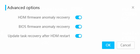
4. Click OK.
Parameters
· HDM firmware anomaly recovery: Enables HDM firmware to recover from anomalies automatically.
· When anomalies occur to the primary HDM firmware, the system uses the backup firmware. The backup firmware attempts to restore the primary firmware with user configuration retained and HDM will switch back to the primary firmware once the primary firmware recovers.
· If the recovery fails, HDM keeps using the backup firmware.
To view the running firmware, navigate to System > System Overview > Product Information.
· BIOS firmware anomaly recovery: Enables the BIOS firmware to recover from anomalies automatically.
¡ If BIOS firmware anomalies are detected, the system attempts to restore the BIOS firmware at next startup with user configuration retained.
¡ If the host cannot be powered on or the BIOS startup times out, HDM recovers the BIOS firmware with the default settings restored, and then attempts to power on the host. This operation might change the BIOS settings.
¡ If the recovery fails, the system no longer attempts to restore the BIOS firmware.
· Update task recovery after HDM restart: Enables update tasks to resume automatically after a restart when anomalies occur.
¡ If the restart occurs at the update preparation stage, the update task fails.
¡ If the restart occurs at update execution, the update task resumes after the restart.
¡ If the recovery fails, the system no longer attempts to resume the update task.
To view the progress of update tasks, click My tasks on the Dashboard page.
Firmware restart
Restart HDM
You can restart HDM to have the new firmware image take effect after a firmware update or when HDM is malfunctioning.
When HDM restarts, all HDM user sessions are closed. These sessions will be automatically re-established after HDM starts up.
HDM restart does not remove the HDM configuration.
Restrictions and guidelines
Do not power on, power off, or power cycle the server during an HDM restart operation. Doing so might cause malfunctioning of some HDM features or operating system errors.
Procedure
1. On the top navigation bar, click Firmware & Software.
2. In the left navigation pane, select Restart Firmware.
The page as shown in Figure 152 opens.
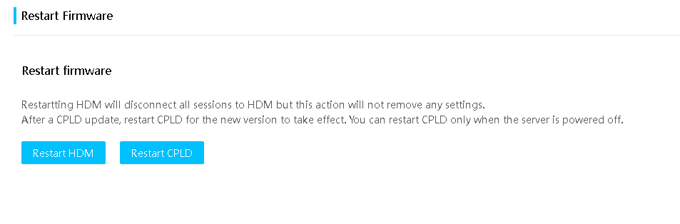
3. Click Restart HDM, and then click OK to confirm the operation.
Restart CPLD
You can restart CPLD to have the new CPLD1, CPLD2, PFRCPLD, SWCPLD, BMCCPLD, and BRCPLD firmware image take effect after a firmware update or when CPLD firmware is malfunctioning.
Restrictions and guidelines
You can restart CPLD only when the server is powered off.
Restarting CPLD will cause HDM to restart immediately.
Procedure
1. On the top navigation bar, click Firmware & Software.
2. In the left navigation pane, select Restart Firmware.
The page as shown in Figure 153 opens.
3. Click Restart CPLD and then click OK to confirm the operation.
Firmware library
During firmware update from HDM Web interface, if you enable firmware backup, HDM will back up the firmware image file to the firmware library automatically.
Perform this task to view information for the backup firmware image files.
Restrictions and guidelines
The maximum capacity of the firmware library is 500 MB. If the available capacity is less than the size of the new image to be backed up, the backup operation fails. To resolve the issue, delete firmware image files from the library manually.
The firmware library saves image files used for recovery by default in case of system exceptions. The files occupy some storage space and the occupied space cannot be released manually. Image files used for scheduled firmware upgrade also occupy some space of the firmware library and the occupied space is released when the scheduled task finishes or is manually cancelled.
Procedure
1. On the top navigation bar, click Firmware & Software.
2. In the left navigation pane, select Firmware library.
Figure 154 Firmware library
3. View the space size for the firmware library, including Used space and Available space.
4. View firmware image file information, including the firmware name, type, version, and size.
5. To start firmware update, click Activate in the Actions column for a firmware image file.
6. To delete a target firmware image file, click Delete in the Actions column.
Users & Security
User management
Manage user accounts, including local users, LDAP users, AD groups and Kerberos groups, to control access to HDM. You can also enable OTP authentication to authenticate HDM users through static and dynamic passwords.
|
|
NOTE: Only the R4700 G6 and R4900 G6 servers support intelligent power saving. |
View local user information
Procedure
1. On the top navigation bar, click Users & Security.
2. In the left navigation pane, select Users.
3. In the work pane, view information about HDM users in the user list.
Figure 155 Viewing local user information
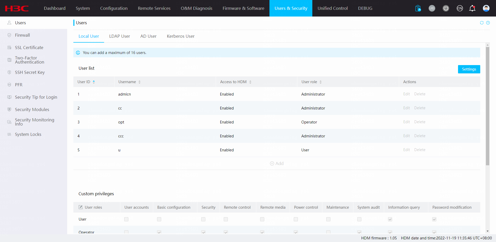
Parameters
· User ID: ID of the user.
· Username: Name of the user.
· Access to HDM: Whether the user can access the HDM Web interface.
· User role: Role of the user, which determines the HDM access privileges of the user.
¡ Administrator—The user has read and write permissions to all features.
¡ Operator—The user has read permission to all features and has write permission to some features.
¡ User—The user has read-only permission.
¡ CustomRoleN—The user has the privileges specified for the custom role by an administrator user. The system supports a maximum of five custom user roles.
¡ None—The user does not have network access permissions. This role is for special use. Do not assign the role to any users.
Configure the password policy for local users
Perform this task to enhance HDM access security by setting rules that the passwords of user accounts must follow.
Restrictions and guidelines
If the length of the password exceeds 20 characters, you cannot access the IPMI interface by using IPMItool. If you modify the password from IPMItool, make sure the length does not exceed 20 characters.
To upload a weak password dictionary, make sure the file name does not exceed 255 characters in length, and contain only letters, digits, and the following special characters: @ ! $ ^ & ( ) _ + . ; [ ] { } - = ~ `
To upload a weak password dictionary, make sure the file size does not exceed 10K, and each weak password does not exceed 40 characters. The file content can include line breaks, lowercase and uppercase letters, digits, spaces, and the following special characters: ` ~ ! @ # $ % ^ & * ( ) _ + - = [ ] \ { } | ; ' : " , . / < > ?
Any characters in the weak password dictionary that do not comply with the rules or exceed the length limit will be deleted after the upload. The content of the uploaded weak password dictionary cannot be empty.
Procedure
1. On the top navigation bar, click Users & Security.
2. In the left navigation pane, select Users.
3. In the work pane, click Settings.
Figure 156 Configuring the password policy
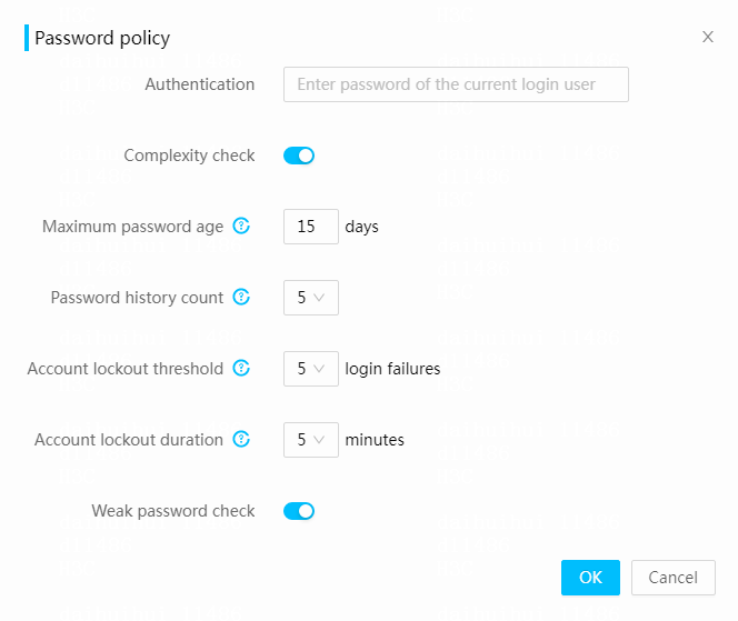
4. In the dialog box that opens, enter your login password, configure the password policy, and then click OK.
5. If the weak password check is enabled, click Weak password dictionary management, and you can perform the following operations in the drop-down list:
¡ Click Upload weak password dictionary. In the dialog box that opens, view the current weak password dictionary, or upload a new weak password dictionary and click OK.
¡ Click Export weak password dictionary to export the current weak password dictionary.
Figure 157 Weak password dictionary management
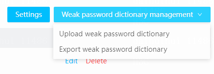
Parameters
· Complexity check: Disable or enable password complexity check.
¡ If this feature is disabled, passwords must meet the following basic complexity requirements:
- 2 to 40 characters in length.
- Case sensitive. Valid characters are letters, digits, spaces, and the following special characters: ` ~ ! @ # $ % ^ & * ( ) _ + - = [ ] \ { } | ; ' : " , . / < > ?
¡ If this feature is enabled, passwords must meet the following enhanced complexity requirements:
- 8 to 40 characters in length.
- Case sensitive. Valid characters are the same as those supported when complexity check is disabled.
- Must contain characters from at least two of the following categories: uppercase letters, lowercase letters, and digits.
- Must contain at least one space or special character.
- Must not be identical to the username or the reverse of the username.
· Maximum password age: Maximum number of days that a password can be used. When a password is about to expire, HDM prompts the user to change the password.
· Password history count: Number of unique passwords that a user must create before an old password can be reused.
· Account lockout threshold: Number of consecutive login failures that will cause a user account to be locked.
· Account lockout duration: Amount of time before a locked account can be used again.
· Weak password check: Select whether to enable weak password check. This feature can identify whether a password is weak. After you enable this feature, a user-configured password cannot be in the weak password dictionary.
Configure privileges for custom users
Perform this task to configure privileges for custom users and change the names of custom user roles.
Restrictions and guidelines
Only users that have basic configuration privilege can upload or download files.
Procedure
1. On the top navigation bar, click Users & Security.
2. In the left navigation pane, select Users.
3. To edit the names of custom user roles,
click the ![]() icon to the left to the User roles field
of the table header.
icon to the left to the User roles field
of the table header.
4. In the Custom privileges section, select access privileges for custom users CustomRole1 to CustomRole5 as needed as shown in Figure 158.
5. Click Save. In the dialog box that opens, enter the login password.
Figure 158 Configuring privileges for custom users
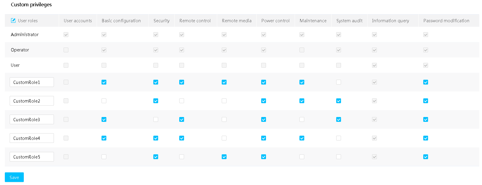
Parameters
· User roles: User role that represents a set of HDM access privileges.
· CustomRoleN: Name of the custom user role. The system supports a maximum of five custom user roles. By default, a custom user role has only the information query privilege. You can edit a custom user role name as needed. A name is a case-sensitive string of 1 to 16 characters, and supports only letters, digits, dots (.), hyphens (-), underscores (_), and at signs (@).
· User accounts: Specify the privilege to manage local users, LDAP users, and AD groups, Kerberos groups, configure OTP authentication, certificate authentication, SSH secret key, license management, secure erasure, import and export configurations, system locks and perform unified control.
· Basic configuration: Specify the privilege to manage asset tags, network configuration, LLDP configuration, Wi-Fi settings, NTP configuration, SNMP configuration, alarm settings (SMTP settings, SNMP trap settings, and syslog settings), event log policy configuration, operation log clearing, video replay, and intelligent security bezel.
· Security: Specify the privilege to configure access services, firewall, SSL certificate, PFR, and security tip for login settings.
· Remote control: Specify the privilege to manage storage configuration, system resource monitoring, BIOS configuration, KVM, H5 KVM, password settings for VNC client login, UID LED, SOL connection mode, and MCA policy. The privilege for power control and mounting media images are not included.
· Remote media: Specify the privilege to configure virtual media configuration, virtual media operation wizard, media mounting from the KVM console, and media mounting from the H5 KVM console.
· Power control: Specify the privilege to manage power configuration, physical power supply button control, NMI control, fan settings, and intelligent power saving.
· Maintenance: Specify the privilege to manage the event log clearing, installation packages, firmware update, firmware library, scheduled tasks, HDM settings restoration, HDM restart, service USB device settings, and CPLD restart.
· System audit: Specifies the privilege to view and save event logs and operation logs, and to manage SDS log downloading.
· Information query: Specify the privilege for a user to view HDM information (excluding event logs and operation logs displaying as well as SDS log downloading). Only an administrator user can view information about other users.
· Password modification: Specify the privilege to modify the local user's own password and SSH key.
Manage local user accounts
Restrictions and guidelines
· You cannot modify the username or user role of a user in a session or delete such a user.
· The user with user ID 1 is an anonymous user reserved by IPMI. The user cannot log in to HDM or be modified from the HDM Web interface.
· Privacy protocols AES192 and AES256 can be used only in combination with authentication protocol SHA256, SHA384, or SHA512.
Prerequisites
Make sure you signed in with the administrator role.
Add a user account
1. On the top navigation bar, click Users & Security.
2. In the left navigation pane, select Users.
Figure 159 Local users

3. Click Add.
4. In the dialog box that opens, configure the user parameters.
Figure 160 Adding a user account
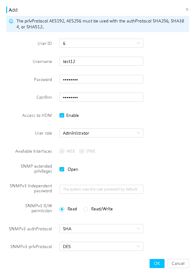
5. Click OK.
Edit a user account
You cannot edit the username of a user with sessions.
To edit a user account:
1. On the top navigation bar, click Users & Security.
2. In the left navigation pane, select Users.
3. Click Edit in the user account entry.
4. In the dialog box that opens, enter your login password and configure the user parameters.
Figure 161 Editing a user account
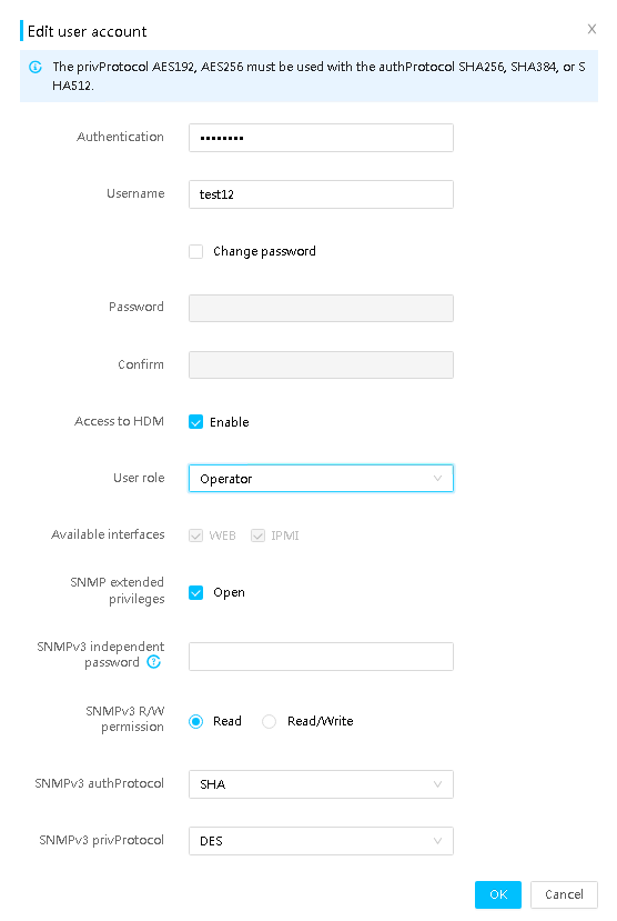
5. Click OK.
Delete a user account
1. On the top navigation bar, click Users & Security.
2. In the left navigation pane, select Users.
3. Click Delete in the user account entry.
4. In the dialog box that opens, enter your login password and click OK.
Parameters
· User ID: ID of the user.
· Username: Specify a username for the user account. The username is a case-sensitive string of 1 to 16 characters. Valid characters are letters, digits, dots (.), hyphens (-), underscores (_), and at signs (@).
· Password: Specify a password for the user account, which must comply with the password policy described in "Configure the password policy for local users."
· Confirm: Enter the password again for confirmation.
· Access to HDM: Enable the user to access HDM as needed. If you do not enable user access, the user cannot access HDM.
· User role: Select a user role, which represents a set of network and service access privileges. Available user roles include:
¡ Administrator—The user has read and write permissions to all features.
¡ Operator—The user has read permission to all features and has write permission to some features.
¡ User—The user has read-only permission.
¡ CustomRoleN—The user has the privileges specified for the custom role by an administrator user. The system supports a maximum of five custom user roles.
¡ None—The user does not have network access permissions. This role is for special use. Do not assign the role to any users.
· Available interfaces: Select the Web and IPMI access privileges for the user as needed.
Web and IPMI access are authorized to administrators and operators by default and cannot be revoked.
· SNMP extended privileges: Select whether to grant the user with SNMP extended privileges. To grant the privileges, you must enable user access to HDM and the user password must contain a minimum of eight characters. If you select SNMP extended privileges, select a privilege from the SNMPv3 R/W permission field. Options include:
¡ Read: The user has read-only permission. This enables the user to perform GET operations and receive traps.
¡ Read/Write: The user has read-and-write permission. This enables the user to perform GET and SET operations and receive traps.
· SNMPv3 independent password: Enter the password to enable the SNMPv3 privilege. By default, the independent password is the same as the local user password. Follow these guidelines when you configure an SNMPv3 independent password:
¡ The password is a string of 8 to 40 characters. Spaces and backslashes (\) are not allowed.
¡ The password must meet the advanced password policy requirements for local user passwords. For more information about the advanced password policy requirements, see "Configure the password policy for local users."
¡ If the local user password contains spaces or backslashes (\), you must specify a new SNMPv3 independent password.
· SNMPv3 authProtocol: Select the SNMP v3 authentication protocol. Options include SHA, MD5, SHA256, SHA384, and SHA512. The default protocol is SHA.
· SNMPv3 privProtocol: Select the SNMP v3 privacy protocol. Options include DES, AES, AES192, and AES256. The default protocol is DES.
User roles and privileges matrix
The supported features or feature menus vary by server model.
The following information describes the privileges that a user role has. A feature or feature menu is inaccessible if your user role does not have the privileges to use that feature or feature menu.
|
Menu/Feature |
Administrator |
Operator |
User |
|
User accounts |
|||
|
Configure a local user account |
√ |
× |
× |
|
Configure LDAP settings |
√ |
× |
× |
|
Configure AD settings |
√ |
× |
× |
|
Configure Kerberos settings |
√ |
× |
× |
|
Configure OTP authentication |
√ |
× |
× |
|
Configure certificate authentication |
√ |
× |
× |
|
Upload SSH key |
√ |
× |
× |
|
License management |
√ |
× |
× |
|
Configure secure erasure |
√ |
× |
× |
|
Import and export configurations |
√ |
× |
× |
|
Perform unified control |
√ |
× |
× |
|
Basic configuration |
|||
|
Set asset tags |
√ |
√ |
× |
|
Configure the HDM dedicated network port |
√ |
√ |
× |
|
Specify the HDM shared network port |
√ |
√ |
× |
|
Configure general settings |
√ |
√ |
× |
|
Configure LLDP |
√ |
√ |
× |
|
Configure Wi-Fi settings |
√ |
√ |
× |
|
Configure NTP servers |
√ |
√ |
× |
|
Configure SNMP settings |
√ |
√ |
× |
|
Manage alert emails |
√ |
√ |
× |
|
Configure SNMP trap settings |
√ |
√ |
× |
|
Configure syslog settings |
√ |
√ |
× |
|
Configure the event log policy |
√ |
√ |
× |
|
Clear operation log entries |
√ |
√ |
× |
|
Configure advanced settings for video replay (download and play videos) |
√ |
√ |
× |
|
Configure the intelligent security bezel |
√ |
√ |
× |
|
Security |
|||
|
Configure services |
√ |
√ |
× |
|
Configure the firewall |
√ |
√ |
× |
|
Configure SSL |
√ |
√ |
× |
|
PFR |
√ |
√ |
× |
|
Security tip for login |
√ |
√ |
× |
|
Remote console |
|||
|
Manage storage configuration |
√ |
√ |
× |
|
Configure the alarm thresholds for system resource monitoring |
√ |
√ |
× |
|
Use KVM remote console (except power control and media mounting) |
√ |
√ |
× |
|
Use H5 KVM remote console (except power control and media mounting) |
√ |
√ |
× |
|
Configure password settings for VNC client login |
√ |
√ |
× |
|
BIOS options |
√ |
√ |
× |
|
Switch SOL connection mode |
√ |
√ |
× |
|
Set the UID LED |
√ |
√ |
× |
|
Set the MCA policy |
√ |
√ |
× |
|
Remote media |
|||
|
Configure virtual media settings |
√ |
√ |
× |
|
Virtual media operation wizard |
√ |
√ |
× |
|
Mount media images from KVM |
√ |
√ |
× |
|
Mount media images from H5 KVM |
√ |
√ |
× |
|
Power control |
|||
|
Power on or power off the server |
√ |
√ |
× |
|
NMI control |
√ |
√ |
× |
|
Meter power (operating mode and power-on policy) |
√ |
√ |
× |
|
Physical power button control |
√ |
√ |
× |
|
Configure global power settings (alarm threshold for the global power consumption and power capping) |
√ |
√ |
× |
|
Configure fan settings |
√ |
√ |
× |
|
Configure processor power states |
√ |
√ |
× |
|
Intelligent power saving |
√ |
√ |
× |
|
Maintenance |
|||
|
Clear event logs |
√ |
× |
× |
|
Update firmware |
√ |
× |
× |
|
Manage installation package |
√ |
× |
× |
|
Manage firmware library |
√ |
× |
× |
|
Manage scheduled tasks |
√ |
× |
× |
|
Restore HDM settings |
√ |
× |
× |
|
Restart HDM |
√ |
× |
× |
|
Restart CPLD |
√ |
× |
× |
|
Manage service USB device settings |
√ |
× |
× |
|
System audit |
|||
|
View and save event logs |
√ |
√ |
× |
|
View and save operation logs |
√ |
√ |
× |
|
Manage SDS log downloading |
√ |
√ |
× |
|
View most recent event notifications |
√ |
√ |
× |
|
Information query |
|||
|
View basic server information |
√ |
√ |
√ |
|
View basic server status information |
√ |
√ |
√ |
|
View server health state |
√ |
√ |
√ |
|
View HDM user sessions |
√ |
√ |
√ |
|
View storage information |
√ |
√ |
√ |
|
View system information |
√ |
√ |
√ |
|
View power information |
√ |
√ |
√ |
|
Display power configuration (operating mode and power-on policy) |
√ |
√ |
√ |
|
Display global power settings (alarm threshold for the global power consumption and power capping) |
√ |
√ |
√ |
|
View history power consumption statistics |
√ |
√ |
√ |
|
View processor power states |
√ |
√ |
√ |
|
View temperature heatmaps |
√ |
√ |
√ |
|
View fan configuration |
√ |
√ |
√ |
|
Display the BIOS settings |
√ |
√ |
√ |
|
View system resource monitoring statistics |
√ |
√ |
√ |
|
View information about the HDM dedicated network port |
√ |
√ |
√ |
|
View information about the HDM shared network port |
√ |
√ |
√ |
|
View general settings |
√ |
√ |
√ |
|
View LLDP information |
√ |
√ |
√ |
|
View Wi-Fi information |
√ |
× |
× |
|
View NTP servers |
√ |
√ |
√ |
|
View license information |
√ |
√ |
√ |
|
View service configuration information |
√ |
√ |
√ |
|
View remote console information |
√ |
√ |
√ |
|
View virtual media information |
√ |
√ |
√ |
|
View SNMP settings |
√ |
√ |
√ |
|
View SOL connection mode information |
√ |
√ |
√ |
|
View BSoD screenshots |
√ |
√ |
√ |
|
View alarm settings |
√ |
√ |
√ |
|
View configuration management information |
√ |
√ |
√ |
|
View POST codes |
√ |
√ |
√ |
|
View intelligent security bezel settings |
√ |
√ |
√ |
|
View service USB device settings |
√ |
√ |
√ |
|
View secure erasure information |
√ |
√ |
√ |
|
View task center |
√ |
√ |
√ |
|
View and download firmware inventory information |
√ |
√ |
√ |
|
View and download system software information |
√ |
√ |
√ |
|
View firmware library information |
√ |
√ |
√ |
|
View scheduled task information |
√ |
√ |
√ |
|
View information about the current local user |
√ |
√ |
√ |
|
View information about the other local users |
√ |
√ |
√ |
|
View LDAP settings |
√ |
√ |
√ |
|
View AD settings |
√ |
√ |
√ |
|
View firewall settings |
√ |
√ |
√ |
|
View the SSL certificate |
√ |
√ |
√ |
|
View OTP authentication settings |
√ |
√ |
√ |
|
View certificate authentication settings |
√ |
√ |
√ |
|
View PFR settings |
√ |
√ |
√ |
|
View the security tip for login |
√ |
√ |
√ |
|
View the security module status |
√ |
√ |
√ |
|
View fan configuration |
√ |
√ |
√ |
|
View unified control information |
√ |
√ |
√ |
|
View intelligent power saving configuration |
√ |
√ |
√ |
|
View UID LED status |
√ |
√ |
√ |
|
Toggle between languages |
√ |
√ |
√ |
|
Access online help |
√ |
√ |
√ |
|
Refresh a page |
√ |
√ |
√ |
|
Sign out HDM |
√ |
√ |
√ |
|
Password modification |
|||
|
Modify the current user's password |
√ |
√ |
√ |
Configure LDAP settings
Lightweight Directory Access Protocol (LDAP) enables you to efficiently access and maintain distributed directory information services over an IP network.
You can enable LDAP authentication and access to HDM with the user accounts in LDAP role groups on the LDAP server.
Prerequisites
Before configuring LDAP settings, make sure an LDAP server is available. For more information, see "Set up an LDAP server."
Procedure
1. On the top navigation bar, click Users & Security.
2. In the left navigation pane, select Users.
3. Click the LDAP User tab.
Figure 162 LDAP User
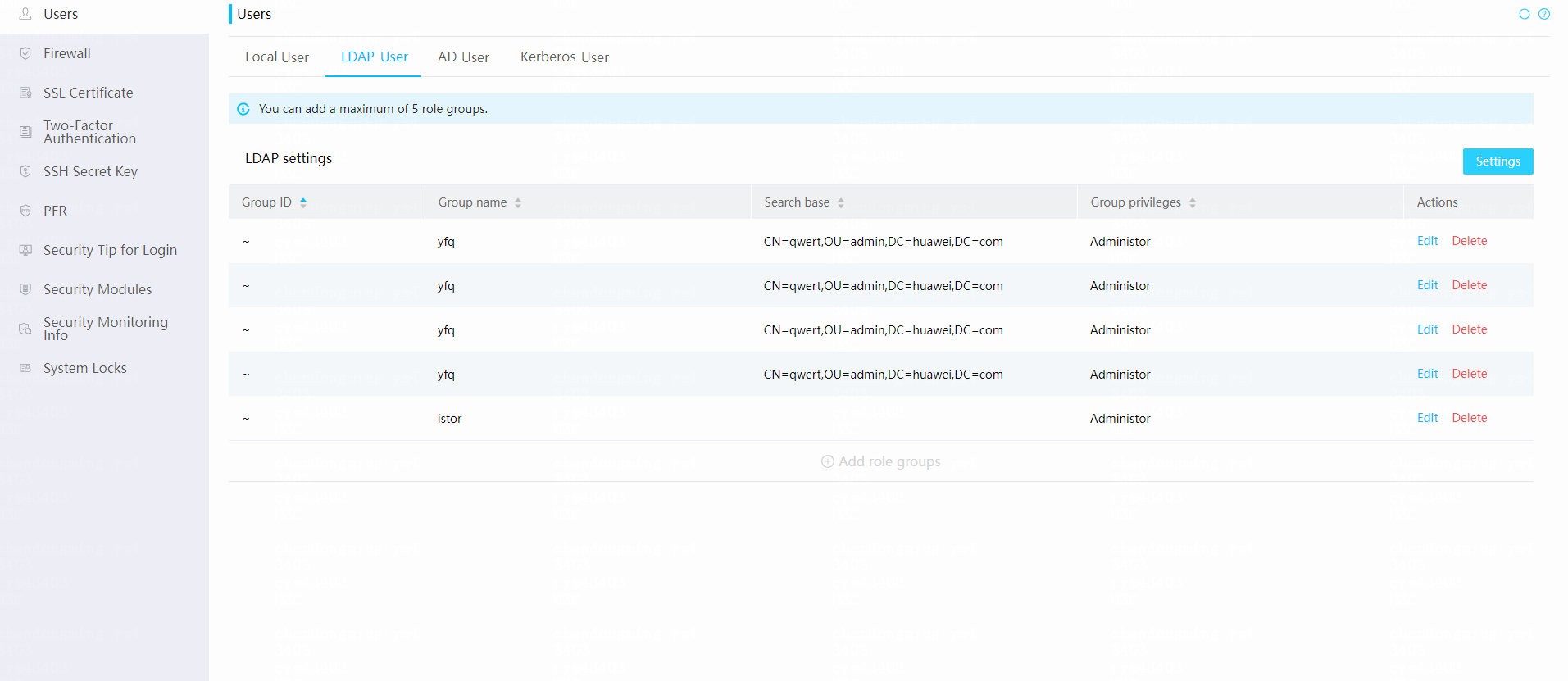
4. In the LDAP Settings section, click Settings.
5. In the dialog box that opens, enter your login password, enable LDAP authentication, and then configure the LDAP parameters.
Figure 163 Configuring LDAP parameters

6. Click OK.
Parameters
· Encryption type: Select the encryption type.
¡ No encryption—Establishes an unencrypted connection with the LDAP server.
¡ SSL—Establishes an SSL encrypted connection with the LDAP server.
· LDAP certificate verification: Enable or disable LDAP certificate verification. For this feature to take effect, you must also enable LDAP encryption.
· Certificate verification level: Select a verification level. Options include:
¡ Demand: Refuses a client to log in to HDM when a certificate error is detected for the client or the client does not have a certificate.
¡ Allows: Allows a client to log in to HDM even if a certificate error is detected for the client or the client does not have a certificate.
· LDAP certificate: Upload the LDAP CA certificate. Only the .cer, .pem, .cert, and .crt formats are supported. The certificate name cannot contain spaces and special characters such as back quote (`), ampersand signs (&), left parentheses ((), right parentheses ()), semi-colons (;), and apostrophes ('). The maximum length of the certificate name is 32 characters. The size of the certificate file cannot exceed 1 MB.
· Common name type: IP address or domain name.
· Server address: IPv4 address, IPv6 address, or domain name of the LDAP server. Do not specify an IPv6 link-local address or an IPv6 multicast address.
· Port number: LDAP service port number, in the range of 1 to 65535. For an SSL connection, the port number is 636 by default. For the remaining types of connections, the port number is 389 by default. Make sure the port number is unique among all services.
· Bind DN: DN information of the LDAP user that is bound to the LDAP server and HDM. The maximum length is 255 bytes. The DN information includes the following comma-separated items:
¡ CN—User login name.
¡ UID—User ID.
¡ OU—Organizational units in ascending order of levels.
¡ DC—Name of the domain to which the user belongs.
· Password: Directory password of the LDAP user.
· Search base: Search base (directory) of the LDAP user in the bind DN on the LDAP server. The maximum length is 255 bytes.
· User identification method: User identification method used by the LDAP server. Supported methods are CN and UID. The user identification method must be consistent with LDAP user information in the bind DN.
Manage LDAP role groups
Add a role group
1. On the top navigation bar, click Users & Security.
2. In the left navigation pane, select Users.
3. Click the LDAP User tab.
4. In the LDAP Settings section, click Add role groups.
5. Configure the role group parameters.
Figure 164 Adding a role group

6. Click OK.
Edit a role group
1. On the top navigation bar, click Users & Security.
2. In the left navigation pane, select Users.
3. Click the LDAP User tab.
4. In the LDAP Settings section, click the Edit link in the role group entry that you want to modify.
5. Enter your login password and modify the parameters.
Figure 165 Editing a role group
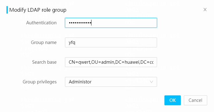
6. Click OK.
Delete a role group
1. On the top navigation bar, click Users & Security.
2. In the left navigation pane, select Users.
3. Click the LDAP User tab.
4. In the LDAP Settings section, click Delete in the role group entry that you want to delete. In the dialog box that opens, enter the HDM login password.
Figure 166 Deleting a role group

Parameters
· Group ID: ID of the role group.
· Group name: Name of an existing role group on the LDAP server.
· Search base: Search base (directory) of the role group on the LDAP server. The maximum length is 255 bytes.
· Group privileges: HDM access privileges of the group.
Configure AD authentication
Perform this task to enable users to access HDM by using the username and password of user accounts in a valid Active Directory (AD) group configured on the AD server.
Prerequisites
Before configuring AD settings, make sure an AD server is available.
Procedure
1. On the top navigation bar, click Users & Security.
2. In the left navigation pane, select Users.
3. Click the AD User tab.
Figure 167 AD Users
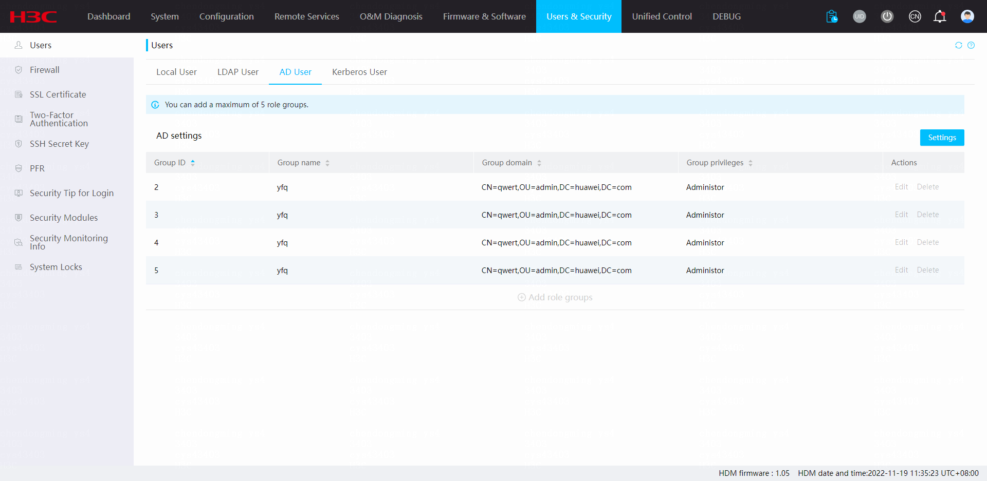
4. In the AD settings section, click Settings.
5. Enter your login password, and select Enable or Disable for AD authentication. If you select Enable, configure AD authentication parameters as needed.
Figure 168 Configuring AD authentication parameters
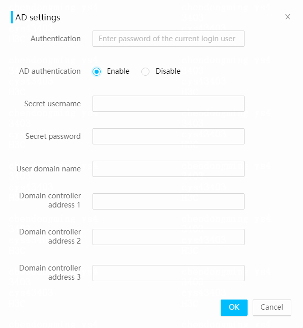
6. Click OK.
Parameters
· Secret username: Enter the username used for logging in to the AD servers, a string of up to 64 characters. The username can contain only digits, letters, or both and must start with a letter. The username is optional.
· Secret password: Enter the password used for logging in to the AD servers, a string of 6 to 96 characters. The password is optional.
· User domain name: Enter the user domain name. The name must conform to the domain name requirements.
· Domain controller address: Enter the IP address or domain name of an AD server. Domain controller address 1 is required.
Manage AD groups
Perform this task to add, edit, or delete AD groups.
Add an AD group
1. On the top navigation bar, click Users & Security.
2. In the left navigation pane, select Users.
3. Click the AD User tab.
4. In the AD settings section, click Add role groups.
5. In the dialog box that opens, configure AD group parameters.
Figure 169 Adding an AD group
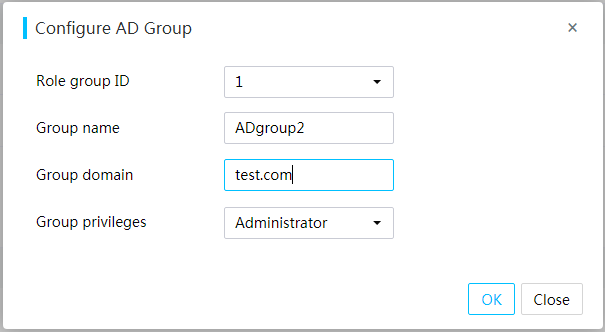
6. Click OK.
Edit an AD group
1. On the top navigation bar, click Users & Security.
2. In the left navigation pane, select Users.
3. Click the AD User tab.
4. In the AD settings section, click Edit for the target AD group from the AD group list.
5. In the dialog box that opens, enter your login password, and edit AD group parameters.
Figure 170 Editing an AD group
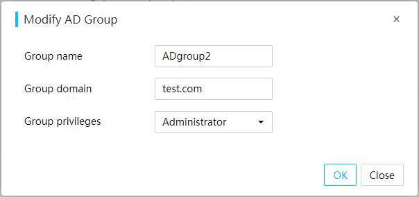
6. Click OK.
Delete an AD group
1. On the top navigation bar, click Users & Security.
2. In the left navigation pane, select Users.
3. Click the AD User tab.
4. In the AD settings section, click Delete for the target AD group from the AD group list. In the dialog box that opens, enter HDM login password.
Parameters
· Role group ID: ID of the AD group.
· Group name: Name of an existing group on the AD server, a string of 1 to 255 characters. Only digits, letters, underscores (_), and hyphens (-) are allowed.
· Group domain: Name of the domain to which the group belongs, a string of 1 to 255 characters. Only digits, letters, underscores (_), hyphens (-), and dots (.) are allowed.
· Group privileges: Network privileges of the group.
Configure Kerberos settings
Perform this task to enable users to access HDM by using the username and password of a user account in a Kerberos role group configured on the Kerberos server. If the Kerberos server domain name is added to the PC as a local intranet zone, you can access HDM directly without entering a username or password. To add a domain name to the PC, access Internet Options > Security > Local intranet > Sites > Advanced, and then enter the domain name in the Add this Web site to the zone field.
This feature requires licenses. For more information about licenses, see "License management."
Prerequisites
Before configuring Kerberos settings, make sure a Kerberos server is available.
Before using Kerberos single-node login, make sure the domain name is accessible. For more information, see DNS configuration in "Network."
To use single-node login in the Mozilla Firefox browser, enter about:config in the address bar and configure the values of network.negotiate-auth.delegation-uris and network.negotiate-auth.trusted-uris as https://.
To use single-node login, make sure the domain has been added to the PC and enter the correct format of the account (account@domain or domain\account). If you do not do so, it may cause no response after successful login.
Restrictions and guidelines
Direct HDM login without using a username and password is not available once two-factor authentication is enabled.
SSH, Telnet, IPMI, and SNMP are not available for Kerberos users.
Procedure
1. On the top navigation bar, click Users & Security.
2. In the left navigation pane, select Users.
3. Click the Kerberos User tab.
Figure 171 Kerberos User
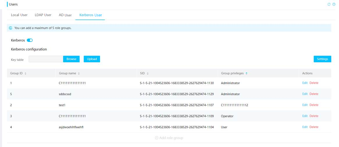
4. Enable or disable Kerberos authentication. In the dialog box that opens, enter your login password.
5. If you enabled Kerberos authentication, click Settings.
6. In the dialog box that opens, enter the login password. Then, configure Kerberos settings.
Figure 172 Configuring Kerberos parameters

7. Click OK.
8. To access HDM directly without a username and password, click Browse in the Key table section, select the keytab file, and click Upload. In the dialog box that opens, enter the login password.
Figure 173 Authentication
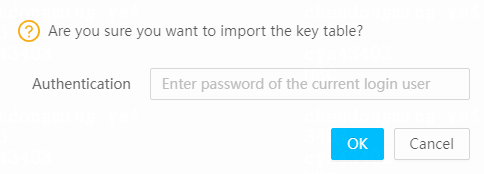
9. After the keytab file is uploaded, you can access HDM by using the username and password or directly from the login page.
Parameters
· Domain name: Enter the Kerberos server domain name. The name must conform to domain name requirements:
¡ The domain name cannot exceed 255 characters
¡ Only uppercase letters are supported.
· Kerberos server address: Enter the IP address of the Kerberos server. The address can be an IPv4 address, IPv6 address, or domain name.
· Kerberos port: Enter the Kerberos port. The Kerberos port must conform to port verification rules. The default port is 88.
Manage Kerberos role groups
Perform this task to add, edit, or delete Kerberos role groups.
Add a Kerberos role group
1. On the top navigation bar, click Users & Security.
2. In the left navigation pane, select Users.
3. Click the Kerberos User tab.
4. In the Kerberos role group section, click Add role group.
Figure 174 Add Kerberos role group
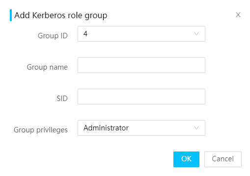
5. Configure Kerberos role group settings in the dialog box that opens.
6. Click OK.
Edit a Kerberos role group
1. On the top navigation bar, click Users & Security.
2. In the left navigation pane, select Users.
3. Click the Kerberos User tab.
4. In the Kerberos role group section, click Edit for the target Kerberos role group in the list.
Figure 175 Edit Kerberos role group
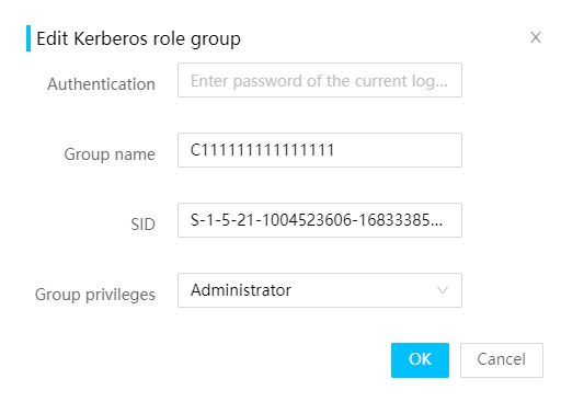
5. In the dialog box that opens, edit the Kerberos role group settings.
6. Click OK. In dialog box that opens, enter the login password. The operation is finished once the verification succeeds.
Delete a Kerberos role group
1. On the top navigation bar, click Users & Security.
2. In the left navigation pane, select Users.
3. Click the Kerberos User tab.
4. In the Kerberos role group section, click Delete for the target Kerberos role group in the list. In dialog box that opens, enter the login password. The operation is finished once the verification succeeds.
Figure 176 Authentication
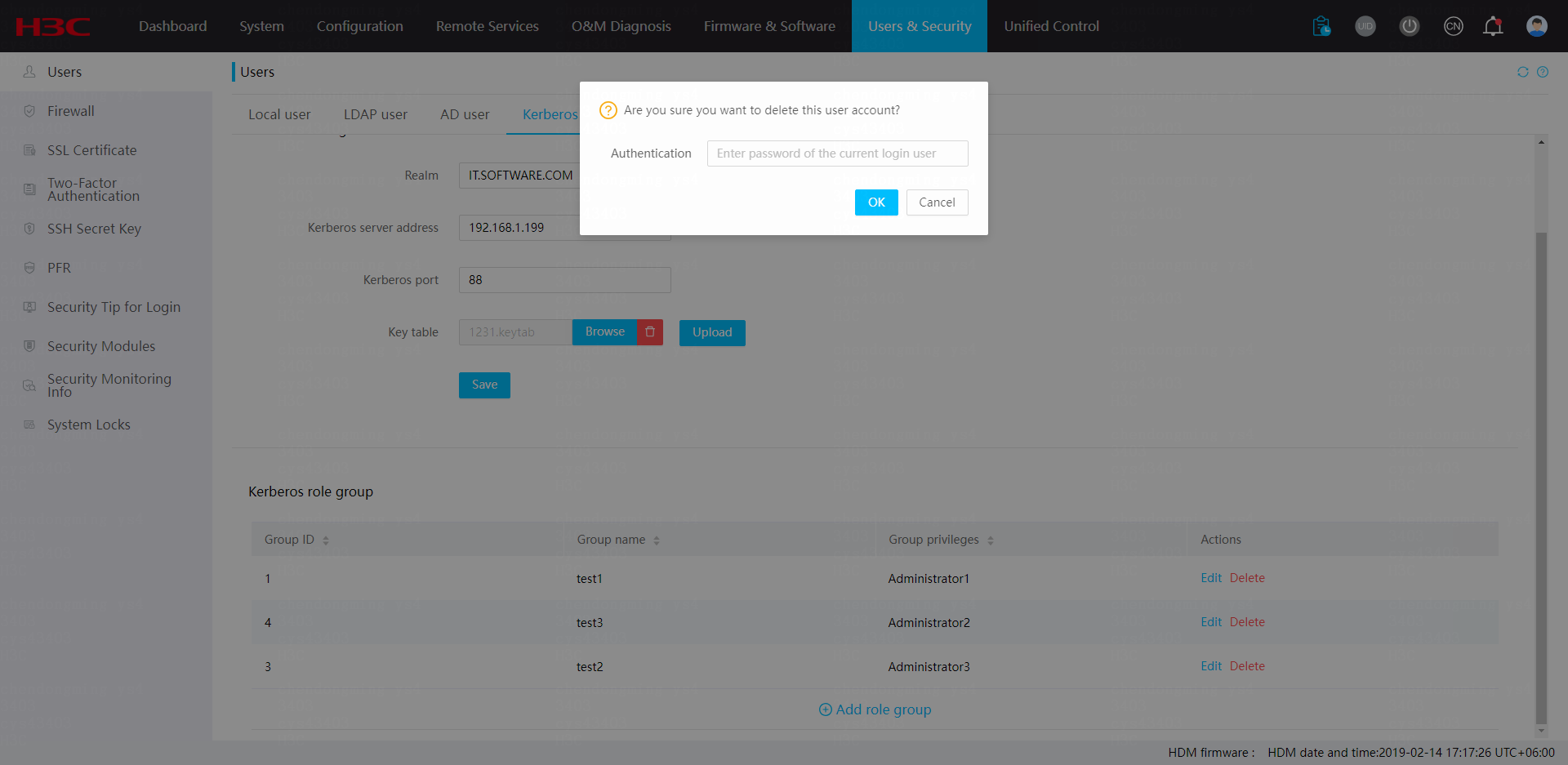
Parameters
· Group ID: ID of a Kerberos role group.
· Group name: Name of an existing role group on the Kerberos server. You can customize the group name based on group permissions for management convenience. The name must meet the following requirements:
¡ Contains only digits, letters, underscores (_), and hyphens (-).
¡ Contains 1 to 255 characters.
· SID: Security Identifier (SID) used for Kerberos role authorization. It is also the objectSID of the role group attribute in the Kerberos server.
· Group privileges: HDM access permission used by the user. Options include:
¡ Administrator: Has read and write permissions to all features.
¡ Operator: Has read permissions to all features and write permissions for specific features. The operator role allows users to perform basic daily operations.
¡ User: Has read-only permissions and cannot edit HDM settings.
¡ CustomRoleN: Custom user roles with administrator-specified permissions. The value of N is in the range of 1 to 5.
Configure firewall
The firewall protects HDM from attacks based on firewall rules that identify accesses to be permitted or blocked.
If HDM cannot be accessed due to improper firewall settings, you can restore the HDM factory settings from the BIOS to clear the firewall rules. For more information, see the BIOS user guide for the server.
Types of firewall rules and their priority order
You can create the following firewall rules:
· Blacklist rules—Block accesses to the HDM server from specific IP addresses or MAC addresses. You can configure a blacklist rule to take effect in the specified time range.
· Whitelist rules—Permit accesses to the HDM server from specific IP addresses of MAC addresses. You can configure a whitelist rule to take effect in the specified time range.
The blacklist rules take precedence over the whitelist rules.
Manage blacklist rules
Use blacklist rules to block accesses from the specified IP addresses and MAC addresses.
Restrictions and guidelines
· You must specify an IP address/IP range, a MAC address, or both for a blacklist rule.
· The time range settings take effect based on the system time in the HDM server and use the same time zone as HDM.
· If you create multiple blacklist rules with the same content, the system displays only one of them.
Add a blacklist rule
1. On the top navigation bar, click Users & Security.
2. In the left navigation pane, select Firewall.
Figure 177 Firewall page
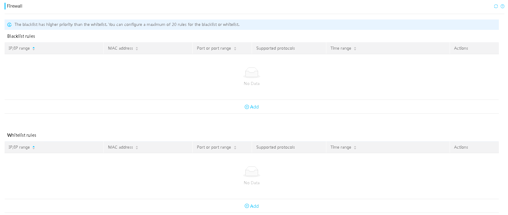
3. In the Blacklist rules section, click Add.
4. In the dialog box that opens, enter at least one of an IP address/IP range, a MAC address, and a port/port range, select UDP, TCP, or both, and set the time range during which the rule takes effect. By default, no validity period is set and the rule is valid permanently.
The port is in the range of 1 to 65535.
Figure 178 Adding a blacklist rule
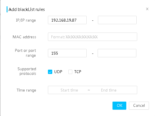
5. Click OK.
Delete a blacklist rule
1. On the top navigation bar, click Users & Security.
2. In the left navigation pane, select Firewall.
3. In the Blacklist rules section, click Delete for the target rule.
Edit a blacklist rule
1. On the top navigation bar, click Users & Security.
2. In the left navigation pane, select Firewall.
3. In the Blacklist rules section, click Edit for the target rule.
4. In the dialog box that opens, edit the rule as needed.
You must enter at least one of an IP address/IP range, a MAC address, and a port/port range. The port is in the range of 1 to 65535.
You can repeat the steps to add another IP address, IP address range, MAC address, port number, or port number range.
Figure 179 Editing a blacklist rule
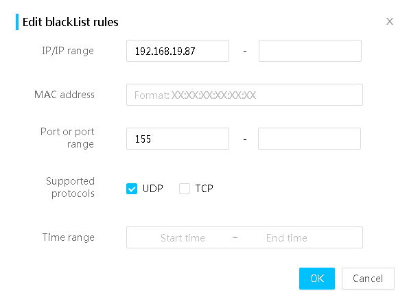
5. Click OK.
Manage whitelist rules
Use whitelist rules to permit accesses from the specified IP addresses and MAC addresses.
Restrictions and guidelines
· First add the IP address and MAC address of the local device to the whitelist before adding any other whitelist rules. If you do not do so, HDM cannot be accessed from the local device.
· If whitelist rules exist, only devices whose addresses have been added to the whitelist can access HDM.
· When you delete a whitelist rule, make sure you fully understand the impact of the operation.
· You must specify an IP address/IP range, a MAC address, or both for a whitelist rule.
· The time range settings take effect based on the system time in the HDM server and use the same time zone as HDM.
· If you create multiple whitelist rules with the same content, the system displays only one of them.
Add a whitelist rule
1. On the top navigation bar, click Users & Security.
2. In the left navigation pane, select Firewall.
3. In the Whitelist rules section, click Add.
4. In the dialog box that opens, enter at least one of an IP address/IP range, a MAC address, and a port/port range, select UDP, TCP, or both, and set the time range during which the rule takes effect. By default, no validity period is set and the rule is valid permanently.
The port is in the range of 1 to 65535.
You can repeat the steps to add another IP address, IP address range, MAC address, port number, or port number range.
Figure 180 Adding a whitelist rule
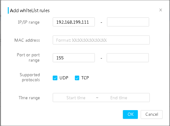
5. Click OK.
Delete a whitelist rule
|
|
CAUTION: Be cautious when you delete a whitelist rule. |
1. On the top navigation bar, click Users & Security.
2. In the left navigation pane, select Firewall.
3. In the Whitelist rules section, click Delete for the target rule.
Edit a whitelist rule
1. On the top navigation bar, click Users & Security.
2. In the left navigation pane, select Firewall.
3. In the Whitelist rules section, click Edit for the target rule.
4. In the dialog box that opens, edit the rule as needed.
You must enter at least one of an IP address/IP range, a MAC address, and a port/port range. The port is in the range of 1 to 65535.
Figure 181 Editing a whitelist rule

5. Click OK.
Manage an SSL certificate
Secure Sockets Layer (SSL) is a protocol for securely transmitting private data over the Internet by using for TCP-based application layer protocols, such as HTTP. It uses keys to encrypt and decrypt data. Using SSL, the Web server and client can have secure data transmission, verify the identity of the data source, and ensure the integrity of the data.
SSL protects HDM accesses from eavesdropping and data tampering and enables HDM users to authenticate the HDM server through SSL certificate authentication.
View SSL certificate
1. On the top navigation bar, click Users & Security.
2. In the left navigation pane, select SSL Certificate.
3. View information about the current SSL certificate.
Figure 182 Viewing SSL certificate information

Upload an SSL certificate and key to HDM
As a best practice, upload an encryption algorithm certificate such as an RSA2048 certificate. It is not recommended to upload a DSA certificate.
Prerequisites
Before you upload an SSL certificate, perform the following tasks:
· Make sure you signed in with the administrator or operator role, or a user account that has the privilege to configure security settings.
· Identify the date and time in HDM on the Dashboard > Summary page, and verify that the HDM system time is in the validity period of the certificate. If the HDM system time is not in the validity period of the certificate, SSL authentication will fail.
· When configuring the common name, organization, organization unit, state or province, and country, the length for the value contains the space at the front or end. However, parameters configured successfully will be displayed with no space.
Procedure
1. On the top navigation bar, click Users & Security.
2. In the left navigation pane, select SSL Certificate.
3. On the SSL Certificate tab, click Upload SSL.
4. Examine information about the current certificate and private key to decide whether a new set of certificate and private key is needed:
¡ Current certificate uploaded at—Date and time when the current certificate was uploaded.
¡ Current private key uploaded at—Date and time when the current private key was uploaded.
Figure 183 Uploading an SSL certificate
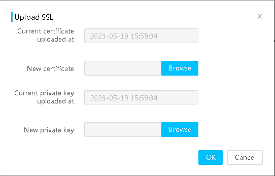
5. Click Browse next to the New certificate field, and then select an SSL certificate file.
6. Click Browse next to the New private key field, and then select a private key file.
7. Click OK.
After the certificate is uploaded, your user session will be disconnected. The HDM server will use the new SSL certificate for authentication during subsequent sign-ins.
8. If you uploaded an SSL certificate generated by yourself, verify that the corresponding root certificate already exists in the client browser. This section uses Chrome to illustrate how to view and add the root certificate of the certification authority to the browser.
a. Open the Chrome browser.
b. From the toolbar, select Settings > Privacy and security.
c. Click the Security tab and then click Manage device certificates.
d. Click the Trusted Root Certification Authorities tab to view the trusted root certification authorities and root certificate expiration date.
e. If the certification authority is not in the list, click Import to import the root certificate.
Figure 184 Viewing and adding the root certificate
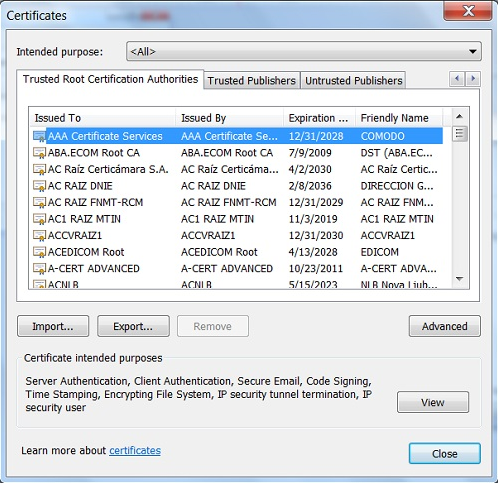
Generate an SSL certificate
Prerequisites
To generate an SSL certificate, you must sign in with the administrator or operator role, or a user account that has the privilege to configure security settings.
Procedure
1. On the top navigation bar, click Users & Security.
2. In the left navigation pane, select SSL Certificate.
3. Click the SSL Certificate tab.
4. Click Generate SSL.
5. Configure the certificate parameters.
Figure 185 Generating an SSL certificate
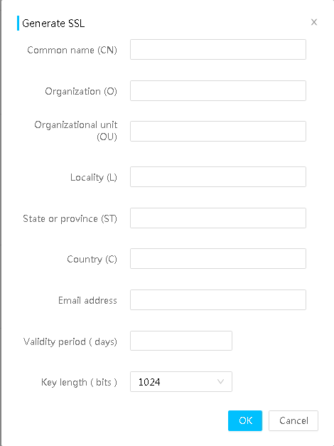
6. Click OK.
7. In the confirmation dialog box that opens, click OK.
If the certificate is generated, you receive a success result message.
The HDM server will use the new SSL certificate for authentication during subsequent sign-ins.
Parameters
· Basic information: Basic information about the current SSL certificate.
¡ Version—Version number of the certificate.
¡ Serial number—Serial number of the certificate. This number is assigned by the certificate authority (CA).
¡ Signature algorithm—Signature algorithm of the certificate.
¡ Public key—Public key information of the certificate.
· Issued by: Certificate authority that issued the certificate.
· Validity: Validity period of the certificate.
¡ Issued at—First valid day of the certificate.
¡ Expires at—Expiration day of the certificate.
· Issued to: Entity to whom the certificate is issued.
· Common name (CN): Full domain name of the HDM server, a string of 1 to 64 characters. Only letters, digits, spaces, underscores (_), hyphens (-), and dots (.) are allowed. The common name cannot be a digits-only string.
· Organization (O): Name of the organization that owns the HDM server, a string of 1 to 64 characters. Only letters, digits, spaces, underscores (_), hyphens (-), dots (.), and commas (,) are allowed. The organization name cannot be a digits-only string.
· Organizational Unit (OU): Name of the unit that owns the HDM server in the organization, a string of 1 to 64 characters. Only letters, digits, spaces, underscores (_), hyphens (-), and dots (.) are allowed. The organizational unit name cannot be a digits-only string.
· Locality (L): City or county where the HDM server resides, a string of 1 to 128 characters. Only letters, digits, spaces, underscores (_), hyphens (-), and dots (.) are allowed. The locality name cannot be a digits-only string.
· State or province (ST): State or province where the HDM server resides, a string of 1 to 128 characters. Only letters, digits, spaces, underscores (_), hyphens (-), and dots (.) are allowed. The state or province name cannot be a digits-only string.
· Country (C): Country or region where the HDM server resides. The country/region is represented as a two-letter code.
· Email address: Email address at which the HDM server owner can be contacted. The address can contain a maximum of 128 characters.
· Validity period: Validity period of the SSL certificate, in the range of 1 to 5475 days.
· Key length: Key length of the certificate.
Configure two-factor authentication
Certificate authentication
To improve HDM reliability for security and avoid user information leakage, HDM provides certificate authentication that requires a client certificate and client private key for each login.
After applying for the root certificate and client certificate file from the certification authority, you can upload them to HDM through certificate authentication, and bind a local HDM user to each client certificate. After successful binding, open a browser and upload the client private key certificate. Once the private key certificate is uploaded, you can enter the HDM login page and select the client certificate as prompted, and then login to HDM as the local user bound to the client certificate.
Restrictions and guidelines
Before enabling certificate, perform the following tasks:
· Apply for a root certificate, client certificate, and client private key from the certification authority.
· Before enabling certificate revocation check, make sure the Web server and the Online Certificate Status Protocol (OCSP) server can reach each other.
· Upload the root certificate and client certificate. Following these restrictions when uploading:
¡ You must upload Base64 coded root certificate and client certificate in the format of .cer, .crt, or .pem. The browser only supports client private key in the . p12 format.
¡ Make sure the length of the certificate name does not exceed 32 characters, and the name cannot contain spaces or special characters, such as back quotes (`), ampersand signs (&), left parentheses ((), right parentheses ()), semi-colons (;), and apostrophes (').
¡ You can upload a maximum of 20 root certificates and 16 client certificates for each root certificate. HDM supports a maximum of 20 client certificates for uploading, and each client certificate can only bind to one HDM local user.
To avoid authentication failures, bind the HDM local user who has permissions to access HDM Web interface.
After you use a client private key to log in to HDM, the root certificate cannot be deleted.
If you want to switch the client private key, clear the browser cache and select another client private key.
Existing sessions might be terminated and new sessions might fail to be established, as shown in Table 16. However, the configuration of these interfaces is not modified. After you disable certificate authentication, these interfaces restore to the status before certificate authentication was enabled.
Table 16 Session consistency and establishment
|
Interface |
Disconnect existing sessions or connections |
Block new sessions or connections |
|
Web |
No |
No |
|
SSH |
No |
Yes |
|
Telnet |
Yes |
Yes |
|
VNC |
Yes |
Yes |
|
Redfish |
Yes |
Yes |
|
IPMI |
Yes |
Yes |
|
SNMPv3 |
No |
Yes |
|
SOL |
Yes |
Yes |
Upload certificates
1. On the top navigation bar, click Users & Security.
2. In the left navigation pane, select Two-Factor Authentication.
Figure 186 Two-Factor Authentication
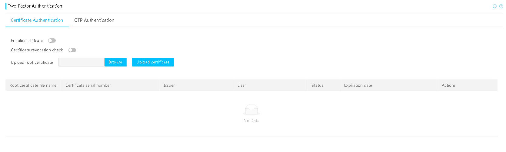
3. Select the Certificate Authentication tab.
4. Click Browse to browse to files, select the target root certificate, and click Upload certificate.
5. In the root certificate list, view the uploaded certificate information.
6. To upload a client certificate, click Upload client certificate in the Actions column. In the dialog box that opens, select and upload the client certificate.
7. To delete a root certificate or client certificate, click Delete in the Actions column.
Bind an HDM local user
1. On the top navigation bar, click Users & Security.
2. In the left navigation pane, select Two-Factor Authentication.
3. Select the Certificate Authentication tab.
4. Click User binding in the Actions column for the target client certificate. In the dialog box that opens, select a user.
5. To unbind the user from a certificate, click User unbinding in the Actions column.
Enable certificate authentication
1. On the top navigation bar, click Users & Security.
2. In the left navigation pane, select Two-Factor Authentication.
3. Select the Certificate Authentication tab.
4. Configure Enable certificate to the enabled state. In the dialog box that opens, enter the HDM login password, and select root certificate to enable.
5. Enable Certificate revocation check as needed. If enabling, in the dialog box that opens, enter the HDM login password.
Log in to HDM by using certificate
1. Open the dialog box for browser certificate management.
2. Click Import to import the client private key. Enter a certificate password if you set a password during the private key generation.
3. Close and open the browse again, access the HDM Web interface, and select the target client certificate as prompted.
4. You can log in to HDM successfully after the certificate passes its verification.
Parameters
Certificate revocation check: During the process of logging into HDM with a client certificate, HDM matches the bound local user and sends the client certificate to the OCSP server to verify its validity. If the certificate has been revoked, the verification fails, and the user cannot log in to HDM.
OTP authentication
About OTP authentication
One-time password (OTP) authentication requires a static password and a dynamic password for each login attempt to provide enhanced network security.
HDM supports DKEY token and can collaborate with an OTP server to provide two-factor authentication for user login. With this feature configured, a user must enter the correct username, static password, and dynamic password obtained from a mobile phone or hardware token to log in to HDM.
Restrictions and guidelines
|
|
CAUTION: Use this feature with caution. Enabling OTP authentication might affect HDM login. |
Before enabling OTP authentication, make sure an OTP server is available and the related settings have been configured on the OTP server. Required settings include HDM management IP address, HDM user accounts (local users and domain users), authentication policy, and tokens.
HDM does not lock a user if the number of user login failures caused by incorrect dynamic passwords reaches the account lockout threshold.
Enabling OTP authentication affects server management as follows:
· You cannot manage the current server through the HDM management address by using management software or features that do not support OTP authentication, for example, UniSystem, HDM Mobile, and HDM unified control of other servers.
· Existing sessions might be terminated and new sessions might fail to be established, as shown in Table 17. However, the configuration of these interfaces is not modified. After you disable OTP authentication, these interfaces restore to the status before OTP authentication was enabled.
Table 17 Session consistency and establishment
|
Interface |
Disconnect existing sessions or connections |
Block new sessions or connections |
|
Web |
No |
No |
|
SSH |
No |
Yes |
|
Telnet |
No |
No |
|
VNC |
Yes |
Yes |
|
Redfish |
Yes |
Yes |
|
IPMI |
Yes |
Yes |
|
SNMPv3 |
No |
Yes |
|
SOL |
Yes |
Yes |
Procedure
1. On the top navigation bar, click Users & Security.
2. In the navigation pane, select Two-Factor Authentication.
3. Click the OTP Authentication tab.
Figure 187 OTP authentication
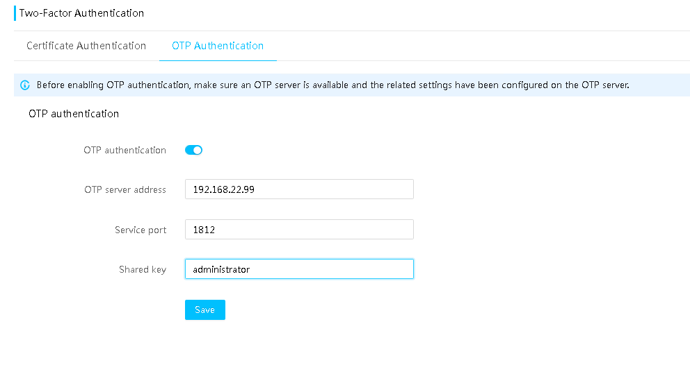
4. Enable Two-factor authentication.
5. Enter the OTP server address, service port, and shared key.
6. Click Save. In the dialog box that opens, enter the HDM login password.
After the configuration, users must enter an HDM username, static password, and dynamic password on the HDM login page to establish new HDM Web sessions.
Figure 188 HDM login

Parameters
· OTP server address: Enter the IP or domain address of the OTP server. Do not specify an IPv6 link-local address or an IPv6 multicast address.
· Service port: Enter the service port number of the OTP server. The default is 1812.
· Shared key: Enter the shared key configured when you add the HDM management IP address to the OTP server. The shared key is a case-sensitive string of 1 to 64 characters. Only letters, digits, and special characters `~!@$%^&*()_+-=[]\{}|;':",./? are allowed.
Upload SSH secret key
Perform this task to upload an SSH secret key, and bind the SSH secret key to a local user for HDM login.
Restrictions and guidelines
At access attempts, the user must also enter the password for the key if a password was specified during key generation on the HDM CLI client. If no password was specified, the user can directly log in to the HDM CLI.
In the current software version, RSA, ECDSA, and ED25519 keys are supported. The length of an SSH key varies by key format.
· For RSA SSH keys, the length can be 1024, 2048, or 4096 bytes.
· For ECDSA SSH keys, the length can be 256, 384, or 521 bytes.
· For ED25519 SSH keys, the length can only be 256 bytes.
HDM supports a maximum of 20 SSH secret keys for uploading, and 1 to 16 users to be bond with each key. Each user can only be bond with one SSH secret key.
Make sure the file name does not exceed 32 characters for each SSH secret key file, and the name cannot contain spaces or special characters, such as back quotes (`), ampersand signs (&), left parentheses ((), right parentheses ()), semi-colons (;), and apostrophes (').
Procedure
1. On the top navigation bar, click Users & Security.
2. In the navigation pane, select SSH Secret Key.
Figure 189 SSH secret key
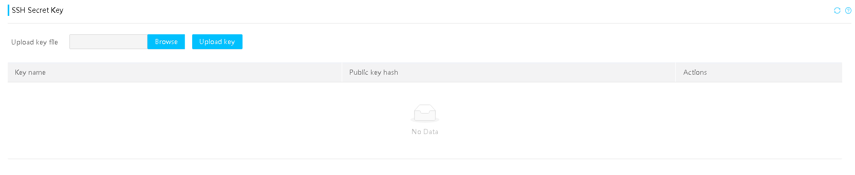
3. Click Browse to browse to files and select the target file.
4. Click Upload key.
5. After uploading, view the SSH key name and public key hash.
6. To bind a user, click User binding in the Actions column. In the dialog box that opens, select the target user and click OK.
7. To unbind a user, click User unbinding in the Actions column.
8. To delete a key, click Delete in the Actions column.
Parameters
Publish hash: Hash of an SSH key.
Configure PFR
Platform Firmware Resiliency (PFR) is a technology used to protect HDM from attacks. If PFR is enabled, PFR will verify the HDM firmware image when HDM starts. The implementation of PFR requires support from the PFRCPLD firmware. PFRCPLD is responsible for protecting HDM and the BIOS firmware and providing checksum and recovery functionality. Servers equipped with the PFRCPLD firmware have this feature enabled by default, while only certain servers support the installation of PFRCPLD firmware.
· If the primary HDM firmware image passes the verification, HDM starts with the primary image.
· If the primary HDM firmware image is damaged, PFR verifies the backup HDM firmware image. If the backup image passes the verification, HDM starts with the backup image.
· If both the primary and backup HDM firmware images are damaged, but the damage to the primary image does not affect HDM start, HDM starts with the primary image.
Hardware and feature compatibility
The R4950 G6 server does not support this feature.
Restrictions and guidelines
· You can update a damaged firmware image to correct it.
· If the main partition of the HDM is damaged, PFRCPLD first attempts to fix the partition. If the partition cannot recover, the entire server system is unable to start up.
· If the BIOS firmware is damaged, PFRCPLD attempts to fix the BIOS firmware. If the firmware cannot recover, HDM still can start up normally.
· Enabling PFR extends the startup time of HDM.
· After PFR is enabled, you can only upgrade the HDM firmware that supports PFR. To use the PFR-incapable HDM firmware of an earlier version, disable PFR first.
Procedure
1. On the top navigation bar, click Users & Security.
2. In the navigation pane, select PFR.
3. Select whether to enable HDM to start with the backup image upon primary image damage. This feature is available only when PFR is enabled.
Figure 190 PFR tab
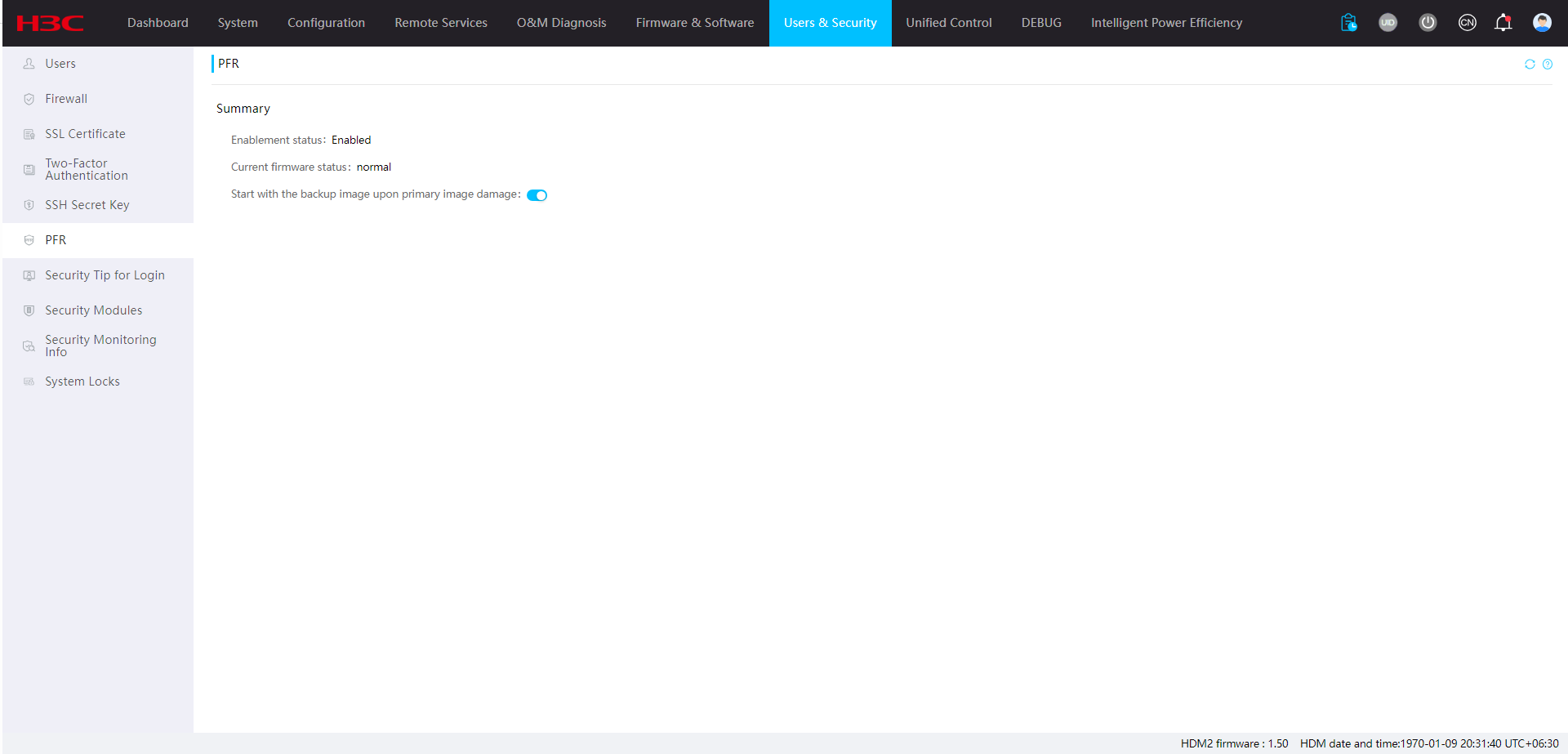
Parameters
· Enablement status: Enablement status of PFR. By default, PFR is enabled.
· Current firmware status: Result of the verification on HDM firmware images during this startup.
· Start with the backup image upon primary image damage: Select whether HDM can start with the backup firmware image. This feature is disabled by default. With this feature enabled, HDM can start with the backup firmware image if the primary image fails the verification but the backup image passes the verification.
Configure the security tip for login
Perform this task to configure the security tip displayed on the login page.
Restrictions and guidelines
The security tip can contain 1 to 1024 bytes. Valid characters include letters, digits, Chinese characters, and special characters except the left angle brackets (<) and right angle brackets (>).
Procedure
1. On the top navigation bar, click Users & Security.
2. In the navigation pane, select Security Tip for Login.
3. Enable Display security tip at login.
4. (Optional.) Configure the security tip.
5. Click Save.
After a successful configuration, you can view the configured security tip on the login page.
Figure 191 Configuring the security tip for login
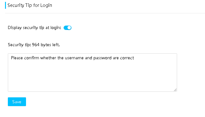
Figure 192 Security tip at login

Security modules
View TPM/TCM status
Trusted Platform Module (TPM) is a microchip embedded in the system board. It stores encryption information (such as encryption keys) for authenticating server hardware and software. Trusted Cryptography Module (TCM) is a trusted computing platform-based hardware module with protected storage space, which enables the platform to implement password calculation. For information about the TPM/TCM module, see the user guide for the server.
Procedure
1. On the top navigation bar, click Users & Security.
2. In the navigation pane, select Security Modules.
3. On the tab that opens, you can view TPM or TCM status. This field displays N/A if both the TPM and TCM are not supported.
Figure 193 Viewing TPM or TCM status
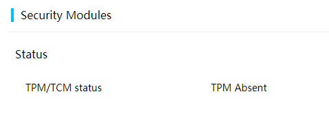
Security monitoring information
This feature allows you to view the status of important security settings and verify whether potential risks exist for HDM static security settings. When risks are detected, you can use this feature to view details and suggestions.
Procedure
1. On the top navigation bar, click Users & Security.
2. In the left navigation pane, select Security Monitoring Information.
Figure 194 Security Monitoring Information

3. Enable Security Monitoring.
After enabling the feature, you can view the status of important HDM security settings. The feature is disabled by default.
4. (Optional.) Ignore the risks of security settings in the Configuration details section.
5. (Optional.) When a security setting is in risk status, to view the warning for the setting, click Risk in the Status column.
Figure 195 Security risk tip
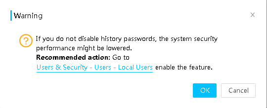
Parameter
· Security settings do not have any risks: No security configuration risk is detected.
· Security settings have risks: One or more security configuration items are identified as risky.
· The overall security status has been ignored: All risky security configuration items are ignored.
· Security monitoring is disabled: Security monitoring is disabled.
· Risk configuration items: Number of security settings that have risks.
· Ignore risk items: Number of security settings of which the risks are ignored.
· Security setting: Names of security settings that are being monitored.
· Value: Current status of the security setting that is being monitored.
· Status: Current risk status of the security setting that is being monitored.
¡ Normal: No risk is detected.
¡ Risk: Potential risk is detected.
¡ Ignore: Risk warning for the security setting is ignored.
· Ignore: Select to ignore risk warning for the security setting. This feature is disabled by default.
Reasons and suggestions for security setting risks are as follows:
Table 18 Reasons and suggestions for security setting risks (1)
|
Security setting |
Risk configuration status |
Reasons and suggestions |
|
|
Account authentication security |
Password complexity check |
Disabled |
Setting a simple password increases the security risk of brute-force attacks. Recommended action: Access Users & Security > Users > Settings to enable complexity check. |
|
Login failure lock (times) |
0 |
Disabling login failure lock might lower the system security performance. Recommended action: Access Users & Security > Users > Settings to set the account lockout threshold. |
|
|
Login failure lock time (min) |
0 |
Disabling login failure lock might lower the system security performance. Recommended action: Access Users & Security > Users > Settings to set the account lockout duration. |
|
|
Password validity (day) |
0 |
If the password validity is not set, long term use of an unchanged password increases the risk of password compromise and might lead to unauthorized access attacks. Recommended action: Access Users & Security > Users > Settings to set a proper password validity period and change the password periodically. |
|
|
Disable history password |
0 |
If you do not disable history passwords, the system security performance might be lowered. Recommended action: Access Users & Security > Users > Settings to set the password history count. |
|
|
Weak password check |
Disabled |
Disabling weak password check might increase the security risk of brute-force attacks. Recommended action: Access Users & Security > Users > Settings to enable Weak password check, or use an IPMI or Redfish command to enable weak password check. |
|
|
LDAP certificate verification |
Disabled |
Disabling LDAP certificate verification might lower the system security performance. Recommended action: Access Users & Security > Users > LDAP User and enable LDAP certificate verification. |
|
Table 19 Reasons and suggestions for security setting risks (2)
|
Security setting |
Risk configuration status |
Reasons and suggestions |
|
|
Application service security |
SNMP community complexity check |
Disabled |
Setting a simple community name increases the security risk of brute-force attacks. Recommended action: Access Remote Services > SNMP to enable the long community string feature. |
|
SNMP v1/v2c |
Enabled |
SNMPv3 provides higher security performance than SNMP v1/v2c. Recommended action: Access Remote Services > SNMP to disable SNMP v1/v2c. |
|
|
IPMI RMCP+ |
Disabled |
RMCP+ is more secure than RMCP. Recommended action: Access Remote Services > Services to enable the secure IPMI service port. |
|
|
VNC password complexity check |
Disabled |
Setting a simple password increases the security risk of brute-force attacks. Recommended action: Access Remote Services > Remote Console > VNC to enable complexity check. |
|
|
KVM encryption mode |
Disabled |
KVM is operating in the unencrypted mode. Recommended action: Access Remote Services > Services to enable the secure KVM service port. |
|
|
Certificate remaining validity (day) |
Within 30 days |
The certificate is about to expire. Recommended action: Access Remote Services > SSL Certificate to replace it with a valid certificate. |
|
|
TLS version |
TLS version includes TLS v1.0 |
A low TLS version is risky. Recommended action: Use IPMI commands to enable a higher TLS version. |
|
|
Default certificate is in use |
Yes |
HDM is using the default self-signed certificate. Recommended action: Access Remote Services > SSL Certificate to import a certificate issued by a trusted authority. |
|
|
Syslog TLS |
Disabled |
Syslog notification is using an insecure transmission protocol. Recommended action: Access O&M Diagnosis > Alarm Settings > Syslog Settings to select the TLS transmission protocol. |
|
|
SMTP TLS encryption |
Disabled |
The system is sending alert emails through SMTP without using TLS encryption. Recommended action: Access O&M Diagnosis > Alarm Settings > Email Notification to enable TLS encryption. |
|
System locks
Perform this task to lock specific server features, configurations, and firmware version to avoid mistaken or malicious modification.
System locks require licensing. For more information about licensing, see "License management."
Procedure
1. On the top navigation bar, click Users & Security.
2. In the left navigation pane, select System Locks.
Figure 196 System Locks
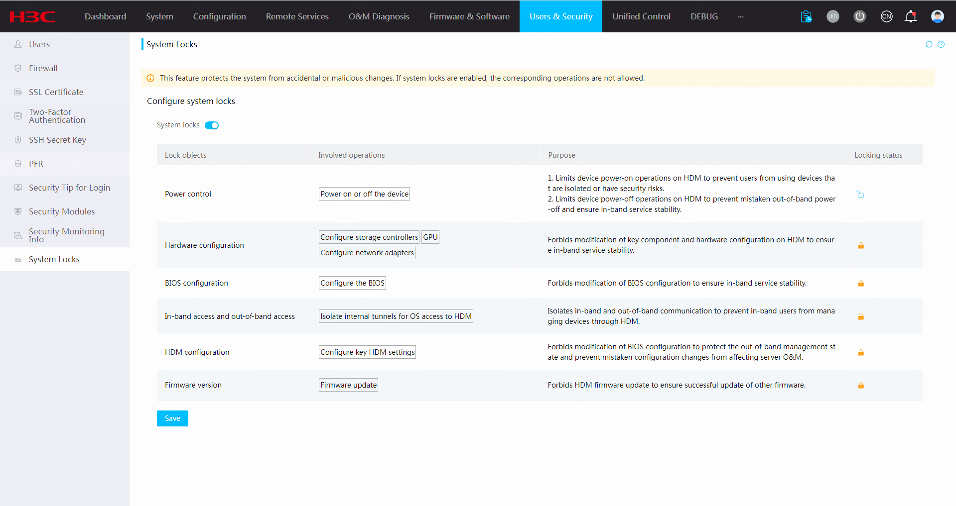
3. Enable the system locks feature.
By default, this feature is disabled.
4. Enable or disable specific system locks in Table 20.
5. Click Save. In the dialog box that opens, specify the user password.
6. Click OK. The system lock settings take effect immediately after the password passes verification.
Table 20 System lock parameters
|
Item |
Description |
|
Power control |
Controls system reset from HDM or by pressing the physical button. |
|
Firmware version |
Controls firmware version update from HDM. |
|
Hardware configuration |
Controls storage controller, GPU, and network configuration from HDM. Options include: · Configure storage controllers, GPUs, and network adapters. · Import RAID configuration files. · Perform storage secure erasing. |
|
BIOS configuration |
Controls BIOS configuration from HDM. Options include: · Configure the BIOS settings. · Import BIOS configuration files. · Update the BIOS with user-defined settings restored or forcibly restored. · Perform BIOS secure erasing. |
|
HDM configuration |
Controls remote modification of HDM configuration. Options include: · Configure user settings (except for export configuration and perform unified control) · Configure general settings (except for event log clearing and video play) · Configure security settings (except for configuring login security information) · Power control (except for power on or power off the server and NMI control) · Remote control (configure MCA policies) · Maintenance (restore the factory defaults of HDM and update HDM with the factory defaults restored) |
|
In-band access and out-of-band access |
Isolate internal tunnels for OS access to HDM, allowing HDM to operate in an independent environment. |
Restrictions and guidelines
· Only users with the administrator privileges can manage system locks.
· System locks take effect on users of all types.
Unified control
Use unified control to manage a maximum of 10 devices in bulk. You can perform the following tasks:
· Launch an H5 KVM remote console
The number of devices that can be managed by unified control depends on the license status. For more information about obtaining licenses, see "License management."
Add devices
Perform this task to add devices one by one or in bulk. You can add a maximum of 10 devices. If you install licenses, see Management Software License Matrixes to obtain the maximum number of devices that are supported.
Restrictions and guidelines
The specified IP range can contain a maximum of 255 IP addresses.
If the number of IP addresses contained in the specified IP range exceeds the HDM-supported upper limit, the system adds the devices whose information is obtained first.
If you change the HDM login username or password of a device after you add it for unified control, the device will become inaccessible from the unified control interface.
Only one user can add devices at a time.
Procedure
1. In the navigation pane, select Unified Control.
Figure 197 Unified control page
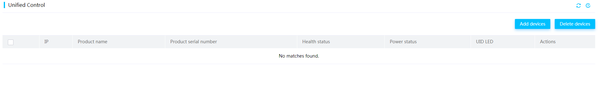
2. Click Add devices.
3. In the dialog box that opens, enter the start and end IP addresses, username, and password of the device, and then click OK.
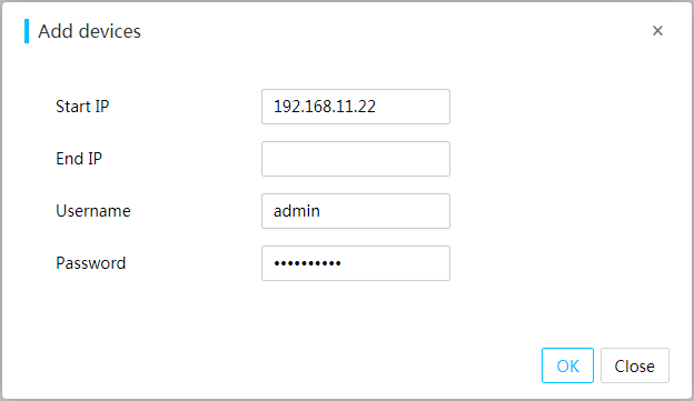
Parameters
· Start IP: Enter the HDM management IP address or the start IP address of the HDM management IP range. Only IPv4 addresses are supported. This field is required.
· End IP: Enter the end HDM management IP address. Only IPv4 addresses are supported. This field is optional.
· Username: Enter a username for HDM login. As a best practice, enter the username of an administrator user. If you enter the username of a non-administrator user, some functions will be unavailable.
· Password: Enter the password for HDM login.
View device information
Perform this task to view information about devices that have been added, including IP addresses, product names, product serial numbers, health status, power status, and UID LED status.
Procedure
In the navigation pane, select Unified Control and view information about the added devices.
Figure 199 Viewing device information
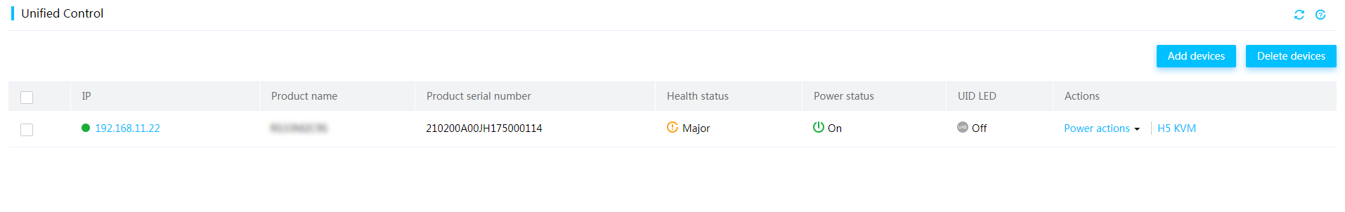
Parameters
· IP: HDM management IP address of the server.
· Health status: Health status of the server.
¡ ![]() Normal—All server components are operating correctly.
Normal—All server components are operating correctly.
¡ ![]() Critical,
Critical, ![]() Major, or
Major, or ![]() Minor—A minimum
of one component is experiencing issues.
Minor—A minimum
of one component is experiencing issues.
· Power status: Power status of the server.
¡ ![]() On—The server is powered on.
On—The server is powered on.
¡ ![]() Off—The server is powered off.
Off—The server is powered off.
· UID LED: Status of the UID LED.
¡ ![]() On—The UID LED
of the server is steady blue.
On—The UID LED
of the server is steady blue.
¡ ![]() Off—The UID LED
of the server is off.
Off—The UID LED
of the server is off.
¡ ![]() Flashing—The UID
LED of the server is flashing blue. The server is
updating firmware or the remote console is launched.
Flashing—The UID
LED of the server is flashing blue. The server is
updating firmware or the remote console is launched.
Access HDM
Perform this task to access the HDM interface of a specific server.
Prerequisites
Make sure the specified user account for the device has the privilege to access HDM. The user privileges are determined by the user role.
Procedure
1. In the navigation pane, select Unified Control.
2. Click the IP address link of the target server.
The HDM interface for the server opens, as shown in Figure 200.
Figure 200 HDM interface for the specified server

Perform power actions
|
|
CAUTION: The force power-off, force system reset, and force power-cycle actions might cause corruption or loss of data. When you perform these actions, make sure you fully understand their impact on the services. |
Perform this task to manage power status of a server.
Prerequisites
Make sure the specified user account for the device has the administrator, operator, or power control role.
To avoid operation failure, make sure the other users are not performing any power actions.
Procedure
1. In the navigation pane, select Unified Control.
2. Identify the entry for the target server.
3. Select a power action for the server as shown in Figure 201.
¡ To warm reboot the server without power cycling the server, select Force system reset.
¡ To shut down the server immediately by force, select Force power-off. This action is equivalent to pressing the power button on the server for five seconds.
¡ To shut down the operating system first, and then remove power from the server, select Graceful power-off.
¡ To start up the server, select Power on.
¡ To power off and then power on the server, select Force power-cycle.
Figure 201 Performing power actions
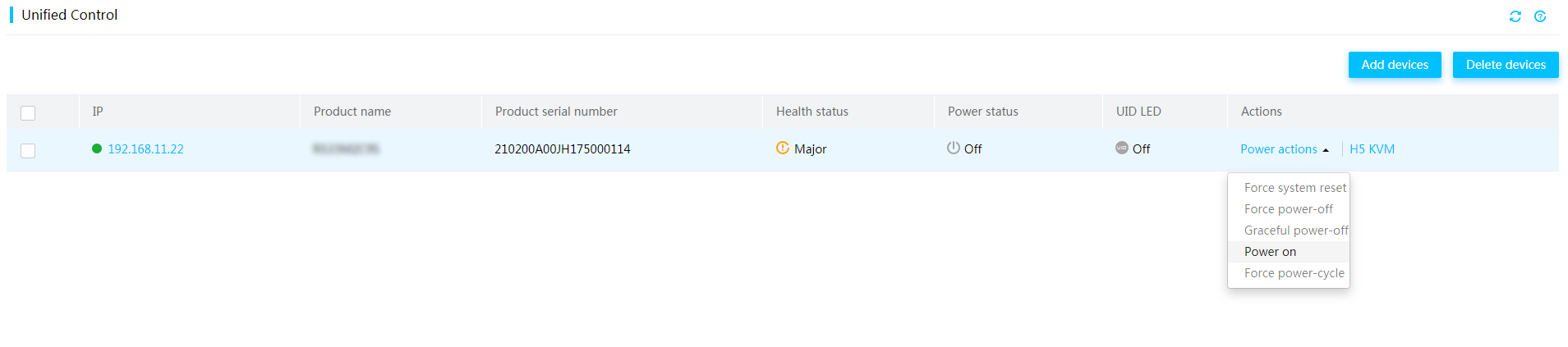
Launch an H5 KVM remote console
Perform this task to operate a server from an H5 KVM remote console.
Prerequisites
Before you can launch an H5 KVM remote console, you must perform the following tasks:
· Make sure the specified user account for the device has the KVM extended privilege. If the user account does not have the privilege, edit the user account. For more information, see "Edit a user account."
· Make sure the user account specified for the device is enabled with the KVM service. If KVM is not enabled, enable the KVM service first. For more information, see "User management."
Procedure
1. In the navigation pane, select Unified Control.
2. Click H5 KVM in the target server entry.
For more information about the H5 KVM remote console, see "Operate the server from H5 KVM."
Figure 202 Remote console for a secondary user
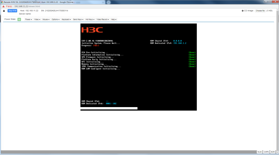
Delete devices
To avoid operation failure, make sure the other users are not performing device deletion actions before you delete devices.
To delete devices:
1. In the navigation pane, select Unified Control.
2. Select one or multiple servers.
3. Click Delete devices.
4. In the dialog box that opens, click OK.
Figure 203 Deleting devices
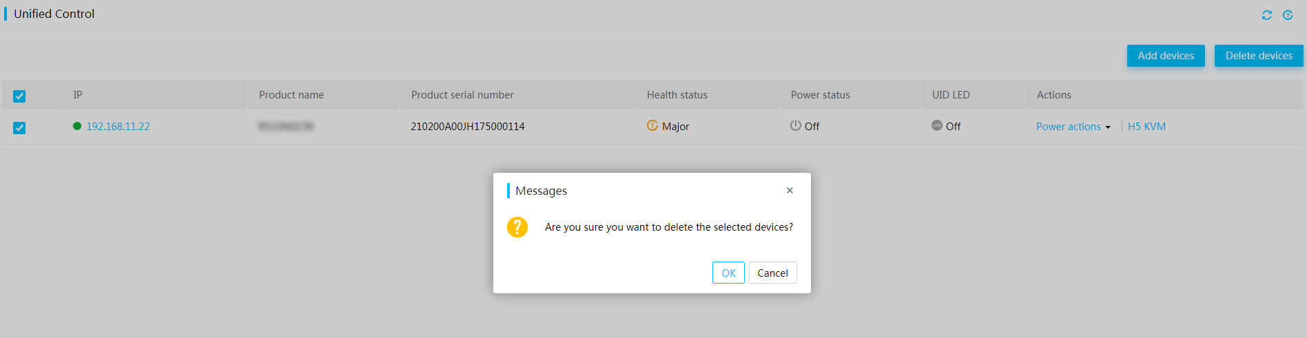
Intelligent power efficiency
Configure power saving mode
Perform this task to enable the power saving mode for the server. The power saving mode is available only for the power sub-system. After you enable this mode, the power sub-system exits the configured power operating mode and enters the power saving mode.
In power saving mode, HDM dynamically adjusts the power operating mode of the server based on the total power consumption to achieve the highest power efficiency. When the total power consumption is high, the power supplies switch to load balancing mode automatically. When the total power consumption is low, the power supplies switch to active/standby mode automatically.
|
|
NOTE: Only the R4700 G6 and R4900 G6 and R4950 G6 servers support intelligent power saving. |
Restrictions and guidelines
· Before you enable the power saving mode, for the configuration to take effect, make sure the current settings meet the following requirements:
¡ The server enters boot options successfully.
¡ All present power supplies are in normal state.
· After you enable the power saving mode, you cannot set the power operating mode manually.
· Enabling intelligent power saving disables cold standby power supply check if the check feature is enabled, and you cannot enable the check feature manually. When intelligent power saving is disabled, the system enables cold standby power supply check automatically.
· After you disable the power saving mode, the power operating mode will restore to the state before you configure the power saving mode.
Procedure
1. On the top navigation bar, click Intelligent Power Efficiency.
2. Select Intelligent power saving.
Figure 204 Intelligent power saving
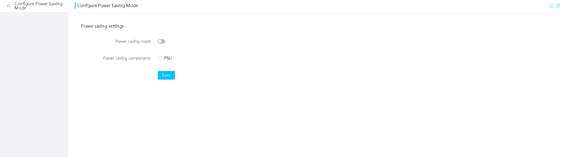
3. Enable the power saving mode as needed.
4. If you enable the power saving mode, select components to be power saved. Only power supplies are available.
Performance configuration
Perform this task to view the current BIOS configuration profile and set the BIOS configuration profile for next startup.
For more information about parameters that can be changed by performance configuration, see the user guide for the BIOS.
Restrictions and guidelines
· This feature is available only for servers installed with Intel processors.
· The configuration takes effect after you restart the BIOS.
Procedure
1. On the top navigation bar, click Intelligent Power Efficiency.
2. In the left navigation pane, select Performance Configuration.
Figure 205 Performance Configuration
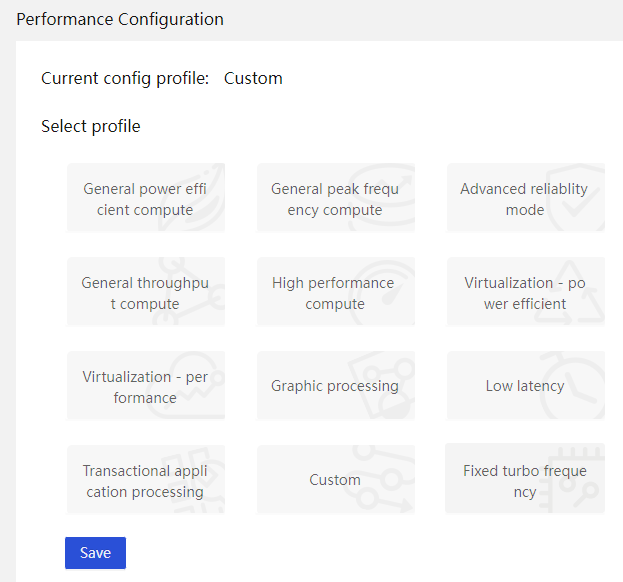
3. View the current configuration profile of the BIOS.
4. Select a profile and click Save. The page prompts whether the operation succeeds.
Parameters
· General power efficient compute: Applicable to most applications and focuses more on power-saving. This profile enables processors to operate in power-saving status and processor chips to enter sleep mode and disables virtualization configuration.
· General peak frequency compute: Applicable to scenarios that require processors or memory to support workloads and focuses more on performance. By disabling power-saving and virtualization configuration, this profile enables processors to operate in active status.
· Advanced relability mode: Applicable to scenarios that require high system stability and maintainability. In this profile, advanced RAS options are enabled, and power-saving options are disabled to reduce the response time of the system to errors.
· General throughput compute: Applicable to scenarios where sustained maximum throughput is required. This profile enables processors to operate at a high efficiency continuously to provide enhanced system performance and the optimal throughput.
· High performance compute: Applicable to scenarios that require high-performance configuration. This profile enables the system to operate at a high efficiency to meet large-scale workload requirements.
· Virtualization-power efficient: Applicable to virtualization scenarios that give priority to power saving. This profile enables all available virtual options and allows processor chips to enter sleep mode.
· Virtualization-performance: Applicable to virtualization scenarios that have high performance requirements. This profile enables all virtualization-related options to support virtualization, and allows the system to operate at a higher frequency by disabling power-saving options to obtain a higher speed.
· Graphic processing: Applicable to GPU servers. This profile forbids virtualization configuration.
· Low latency: Applicable to scenarios that require the minimal compute latency. This profile might disable management features that cause compute latency.
· Transactional application processing: Applicable to service application scenarios such as database systems.
· Custom: Uses the BIOS default settings. Note that this option does not allow users to customize any settings.
· Fixed turbo frequency: Applicable to scenarios that require fixed turbo frequency. This profile is implemented through an out-of-band manner to exclude the operating system from frequency adjustment.
Performance consultant
Perform this task to view server performance indicators and obtain the current and recommended workload profiles.
This feature requires licenses. For more information about licenses, see "License management."
|
|
NOTE: · This feature is available only for servers installed with Intel processors. · If the recommended configuration is the same as the existing configuration, no recommendation will be given and the page will display a hyphen (-). · NUMA identification data and recommended configuration for sub-NUMA clustering can be displayed after you install and run FIST SMS in the operating system. For more information, see FIST SMS User Guide. |
Intelligent load configuration
Perform this task to obtain the recommended workload profile configuration and configure the workload profile. This feature is realized based on system resource monitoring and workload profiles of the BIOS.
Restrictions and guidelines
The configuration takes effect after you restart the BIOS.
Procedure
1. On the top navigation bar, click Intelligent Power Efficiency.
2. In the left navigation pane, select Performance Consultant.
3. Click the Intelligent load config tab.
Figure 206 Intelligent load config
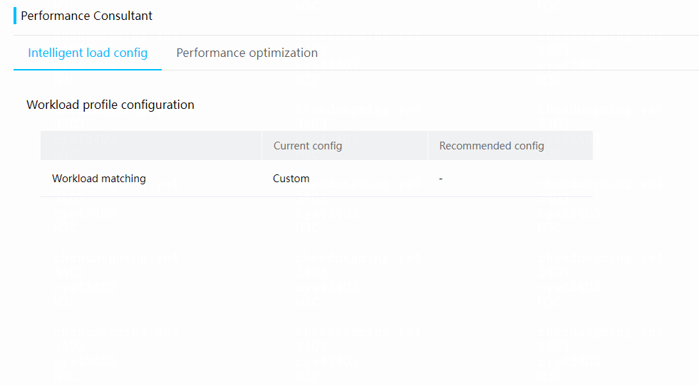
4. To change the current workload configuration to the recommended configuration, click the configure icon in the Recommended config column.
Figure 207 Recommended config
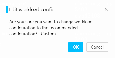
5. In the dialog box that opens, click OK.
Performance optimization
Perform this task to view the workload characteristics by time, view the current and recommended optimization settings, and adjust the settings.
Restrictions and guidelines
The configuration takes effect after you restart the BIOS.
Procedure
1. On the top navigation bar, click Intelligent Power Efficiency.
2. In the left navigation pane, select Performance Consultant.
3. Click the Performance optimization tab.
Figure 208 Performance optimization
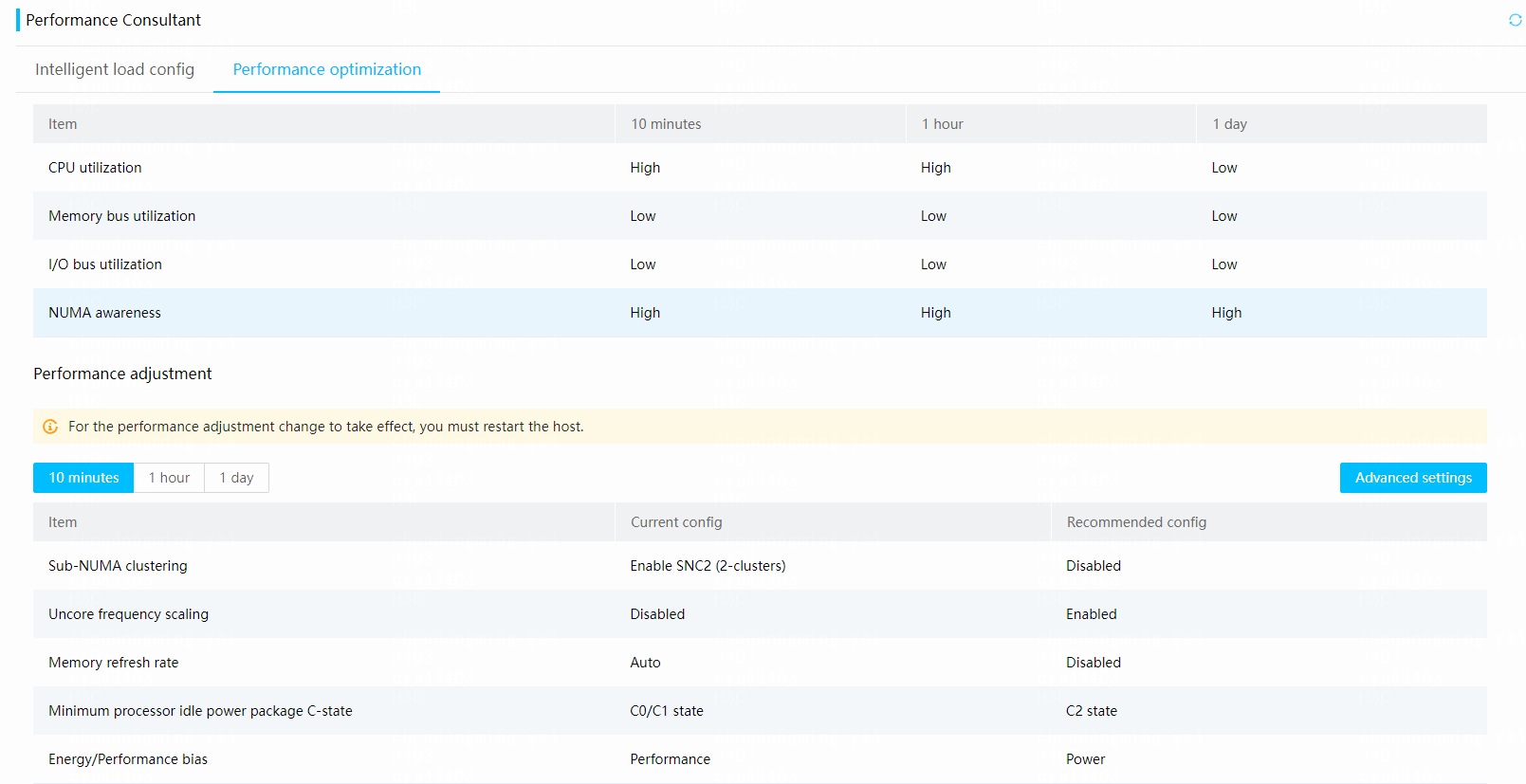
4. View the workload characteristics by time.
5. To view the current and recommended optimization settings for a specific period, click 10 minutes, 1 hour, or 1 day in the Performance Adjustment section.
Figure
209 Performance Adjustment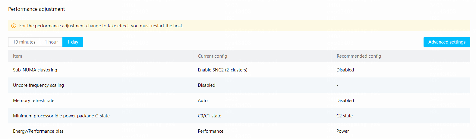
6. To change the current optimization settings, click Advanced settings. In the dialog box that opens, configure the parameters and click OK. The recommended settings are all marked with (recommended).
Figure 210 Advanced settings
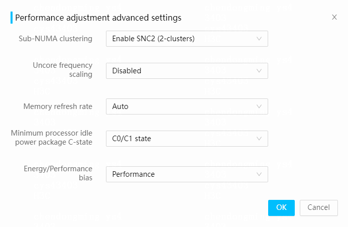
Parameters
Workload characteristics:
· CPU utilization: Displays the CPU usage level calculated based on the average CPU usage of a specific period.
· Memory bus utilization: Displays the memory usage level calculated based on the average memory bus usage of a specific period.
· I/O bus utilization: Displays the I/O bus usage level based on the average I/O bus usage of a specific period.
· NUMA awareness: Displays the NUMA usage level calculated based on the average NUMA (Non-uniform memory access) usage of a specific period.
· 10 minutes: Based on data collected at intervals of 10 minutes. If FIST SMS is installed, the system uses data of FIST SMS. If FIST SMS is not installed, the system uses data of the BIOS.
· 1 hour: Based on data collected at intervals of 1 hour. If FIST SMS is installed, the system uses data of FIST SMS. If FIST SMS is not installed, the system uses data of the BIOS.
· 1 day: Based on data collected at intervals of 1 day. If FIST SMS is installed, the system uses data of FIST SMS. If FIST SMS is not installed, the system uses data of the BIOS.
Performance adjustment:
· 10 minutes: Based on data collected at intervals of 10 minutes. If FIST SMS is installed, the system uses data of FIST SMS. If FIST SMS is not installed, the system uses data of the BIOS.
· 1 hour: Based on data collected at intervals of 1 hour. If FIST SMS is installed, the system uses data of FIST SMS. If FIST SMS is not installed, the system uses data of the BIOS.
· 1 day: Based on data collected at intervals of 1 day. If FIST SMS is installed, the system uses data of FIST SMS. If FIST SMS is not installed, the system uses data of the BIOS.
· Sub-NUMA clustering: Shortens the latency from LLC (Last Level Cache) to the memory. Options include Auto, Disabled, Enable SNC2 (2-clusters), and Enable SNC4 (4-clusters).
· Uncore frequency scaling: Enables the system to distribute power in a more proper manner to maximize performance. Options include Enable and Disabled.
· Memory refresh rate: Adjusts the memory automatic refresh rate. Options include Auto, Disabled, and Enabled.
· Minimum processor idle power package C-state: Defines different power states for processors. Options include C0/C1 state, C2 state, C6 (non-Retention) state, C6 (Retention) state, No Limit, and Auto.
· Energy/Performance bias: Adjusts the power consumption and performance preference. Options include Performance, Balanced Performance, Balanced Power, and Power.
Common operations
This section introduces common operations in HDM configuration.
Configure virtual media
Mount images through a Windows CIFS server
Common Internet File System (CIFS) allows HDM to access files on a remote server. Windows OSs are embedded with CIFS software and do not require CIFS installation.
This section uses Windows 7 as an example.
To mount images through a Windows CIFS server:
1. Copy the target image file to a local path. This section takes D:\IMAGE 2 as an example.
Figure 211 Copying an image file to a local path
2. Configure file sharing.
a. Right-click the IMAGE 2 file folder, select Share with > Specific people.
b. Add users as needed. This section uses UserA as an example.
Figure 212 Configuring file sharing settings
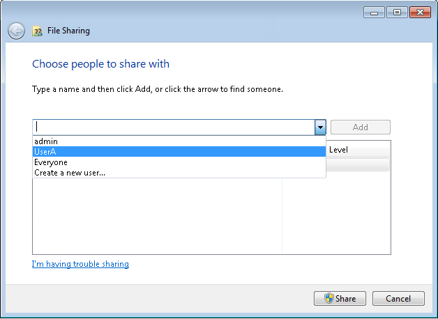
c. Select a Read/Write permission for each user from the Permission Level column.
Figure 213 Adding a user
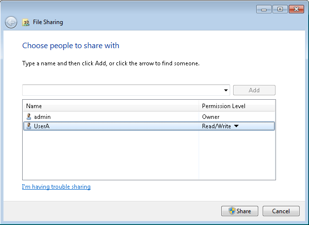
3. Access HDM and configure media mounting settings.
a. On the top navigation bar, click Remote Services.
b. In the left navigation pane, select Virtual Media.
c. In the work pane, click Settings.
d. In the dialog box that opens, enable remote media.
e. Select CD/DVD as the media type.
f. Specify the IP address of the CIFS server and IMAGE2 as the source path. In this example, the server address is 192.168.32.48.
g. Select CIFS as the shared file system.
h. Enter the username and password for access to the shared image file.
Figure 214 Configuring media mounting settings

4. Click OK.
The Virtual Media page displays mounted images.

Mount images through a Linux CIFS server
Common Internet File System (CIFS) is an open version of Server Messages Block (SMB) and allows applications to access files on a remote server.
To set up a Linux CIFS server, you must install the Samba software on the device.
This section uses Red Hat Enterprise Linux 7.3 as an example.
Install and configure Samba
1. Execute the yum –y install samba samba-common samba-client command to install Samba.
The samba-common and samba-client keyword represent the Samba server and Samba client, respectively. As a best practice, specify both keywords to install both the server and the client.
2. Execute the yum list installed | grep samba command to verify that both the Samba server and Samba client have been installed successfully.
3. Execute the testparm command to verify that Samba is configured correctly as shown in Figure 216.
Figure 216 Verifying Samba parameters
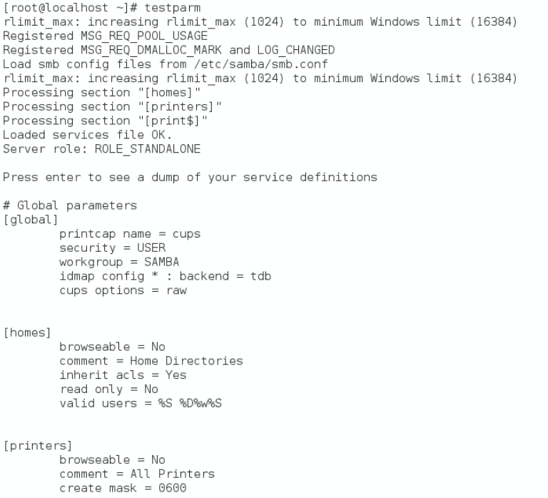
4. Execute the systemctl start smb command to start the Samba service and execute the systemctl status smb command to verify that the service operates correctly.
5. Disable the firewall and disable SELinux.
systemctl stop firewalld
getenforce
setenforce 0
6. Execute the pdbedit –L command to verify that Samba users exist. If no user exists, execute the smbpasswd -a username command to add a user. In this example, the username is ldt.
Make sure the added user already exists in the server OS. To view existing users in the OS, execute the cat /etc/passwd command.
Figure 217 Adding a Samba user
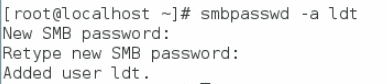
7. Execute the smbclient -L //OS_IP_address command to access the Samba server. In this example, the address is 10.99.205.165.
Figure 218 Accessing the Samba server
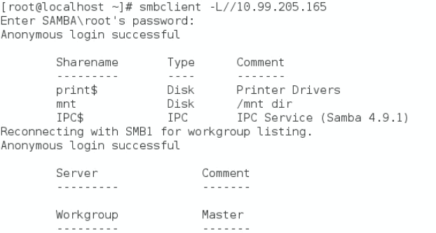
8. Edit the /etc/samba/smb.conf configuration file to create a shared file path. In this example, the path is /test.
vi /etc/samba/smb.conf
[mnt]
comment = /mnt dir
path = /test
9. Execute the systemctl restart smb command to restart Samba.
10. Upload the file to share to the path. In this example, the file is named test.iso.
Mount an image to HDM
1. Access HDM.
2. On the top navigation bar, click Remote Services.
3. In the left navigation pane, select Virtual Media.
4. In the work pane, click Settings.
5. In the dialog box that opens, enable remote media.
a. Select CD/DVD as the media type.
b. Specify the IP address of the Samba server and /mnt as the source path. In this example, the server address is 10.99.205.165.
c. Select CIFS as the shared file system.
d. Enter the username and password of a Samba user.
e. (Optional.) Enter a domain name.
Figure 219 Configuring media mounting settings
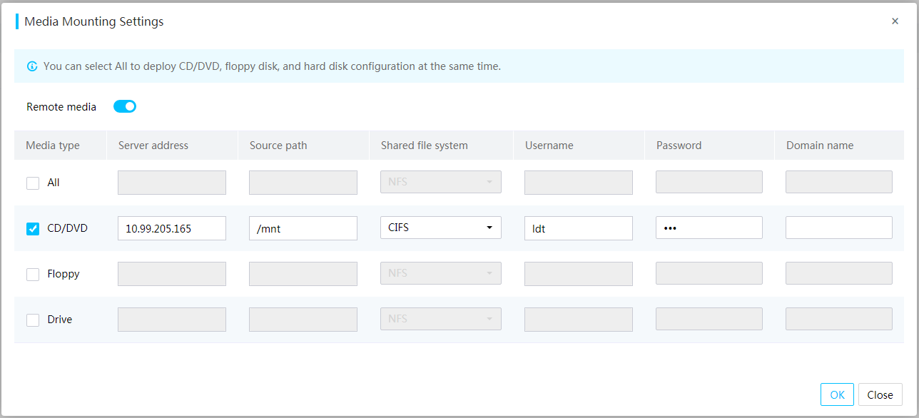
6. Click OK.
The Virtual Media page displays mounted images.
Figure 220 Virtual Media page
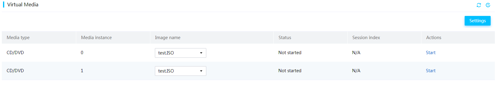
Import HDM configuration
Import HDM user accounts
Restrictions and guidelines
Make sure the server model in the configuration file to import is consistent with the actual server model.
The password fields are empty in a configuration file exported from a server. To import the configuration file to its source server, you can leave the password fields empty or specify passwords as needed. To import the configuration file to another server of the same model, you must specify the passwords in the configuration file.
Procedure
1. Open the configuration file, and search for User Accounts.
Figure 221 Searching for user account information

2. To edit the password of an existing user, delete the comment statement for the user, and then set the new password.
To retain the password of an existing user, leave the password field for the user empty.
If the complexity check field displays 1 in Figure 221, make sure the password you enter meet the complexity requirements.
Figure 222 Configuring a new password

3. To add a new user account, delete the comment statement for the user, and then specify the username and password.
The username and password fields are required for a new user account.
If the complexity check field displays 1 in Figure 221, make sure the password you enter meet the complexity requirements.
Figure 223 Deleting the comment statement
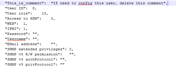
Figure 224 Setting the username and password
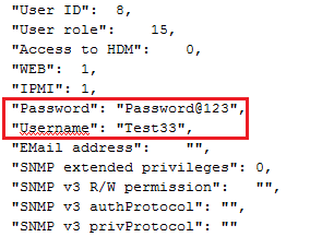
4. To configure the role of a user and enable access to HDM, set the User role and Access to HDM fields, respectively. For supported options of the fields, see Table 21.
Figure 225 Configuring user privileges
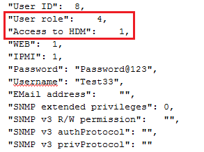
5. Modify miscellaneous settings as needed.
For more information about the configurable fields, see Table 21.
Table 21 Configurable item description
|
Item |
Description |
|
role customrole 1 through 5 |
Privileges of custom user roles 1 through 5. Each role custom field displays the decimal number equivalent of an 9-bit binary number, where each bit represents a privilege as follows: · Bit 0—Remote control. · Bit 1—Remote media. · Bit 2—Security configuration. · Bit 3—User account configuration. · Bit 4—Basic configuration. · Bit 5—Power control. · Bit 6—Maintenance. · Bit 7—Information query. · Bit 8—Password modification. The bit value indicates the enablement status of a privilege as follows: · 1—Enabled. · 0—Disabled. |
|
User ID |
User ID, in the range of 2 to 16. A user ID must be unique. |
|
User role |
Specify the role of the user. · 2—User. · 3—Operator. · 4—Administrator. · 6—CustomRole 1. · 7—CustomRole 2. · 8—CustomRole 3. · 9—CustomRole 4. · 10—CustomRole 5. · 15—None. |
|
Access to HDM |
Enter 0 or 1 to disable or enable access to HDM. |
|
WEB |
Enter 0 or 1 to disable or enable the Web extended privilege. |
|
IPMI |
Enter 0 or 1 to disable or enable the IPMI extended privilege. |
6. Save and import the configuration file.
a. On the top navigation bar, click O&M Diagnosis.
b. In the left navigation pane, select Manage Configuration.
c. Import the configuration file.
The configuration takes effect immediately.
Figure 226 Importing the configuration file
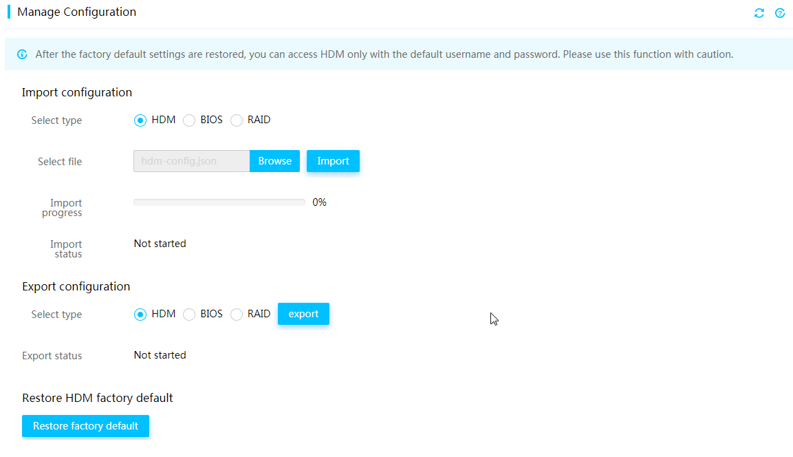
7. To verify the configuration, re-sign in to HDM after HDM restarts and access the Users & Security > Users page to view HDM user accounts.
Figure 227 Re-signing in to HDM

Figure 228 Viewing user accounts

Import SNMP trap settings
1. Open the configuration file, and search for SNMPTrap.
Figure 229 Searching for SNMP trap settings
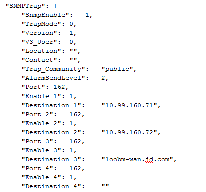
2. Modify SNMP trap server settings. For example:
¡ Set the Destination_2 address to 10.99.160.75 and the Port_2 field to 161.
¡ Set the Enable_3 field to 0 to disable the SNMP trap server.
¡ Set the Destination_4 address to 10.99.160.70.
Figure 230 Modifying SNMP trap server settings
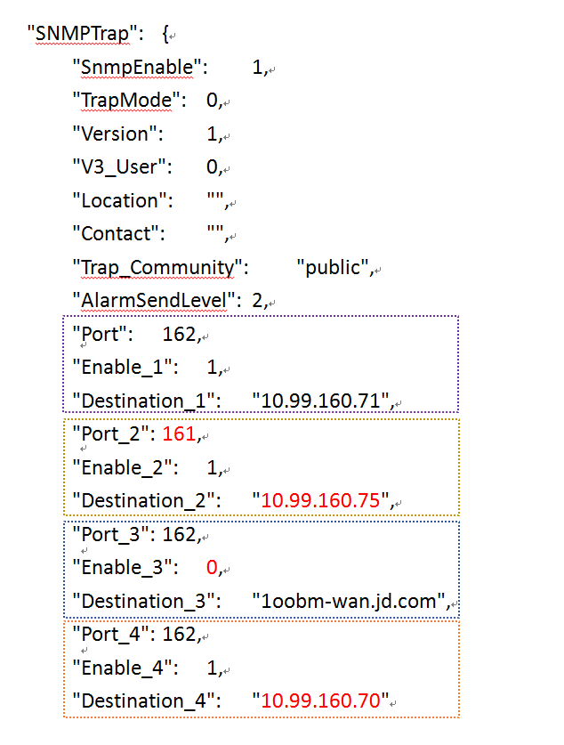
3. Modify miscellaneous SNMP trap settings as needed.
For more information about configurable SNMP trap settings, see Table 22.
Table 22 Configurable item description
|
Item |
Description |
|
SnmpEnable |
Enter 0 or 1 to disable or enable SNMP trap notification. |
|
Trap Mode |
Enter an SNMP trap mode. Options include: · 0—Node mode. · 1—Event mode. |
|
Version |
Enter an SNMP version. Options include: · 0—v1. · 1—v2c. · 2—v3. |
|
V3_User |
Enter a username used by the system to send SNMPv3 traps. |
|
Location |
Enter the location of the server, a string of up to 31 bytes. |
|
Contact |
Enter contact information, a string of up to 31 bytes. |
|
Trap_Community |
Enter the trap community string for authentication on the manager. The value range is 1 to 31 characters. The default value is public. |
|
AlarmSendLevel |
Severity levels of SNMP traps. Options include: · 0—Minor + Major + Critical. · 1—Major + Critical. · 2—All. |
|
Port-Port_8 |
Enter the port number at which the destination host receives SNMP traps. The value range is 1 to 65535. The default port number is 162. |
|
Enable_1-Enable_8 |
Enter 0 or 1 to disable or enable an SNMP trap server. |
|
Destination_1-Destination_8 |
IP or domain address of a destination host that receives SNMP traps. |
4. Save and import the configuration file.
a. On the top navigation bar, click O&M Diagnosis.
b. In the left navigation pane, select Manage Configuration.
c. Import the configuration file.
The configuration takes effect immediately.
5. To verify the configuration, open the SNMP trap packet settings page, and then view SNMP trap settings.
Figure 231 Viewing SNMP trap settings
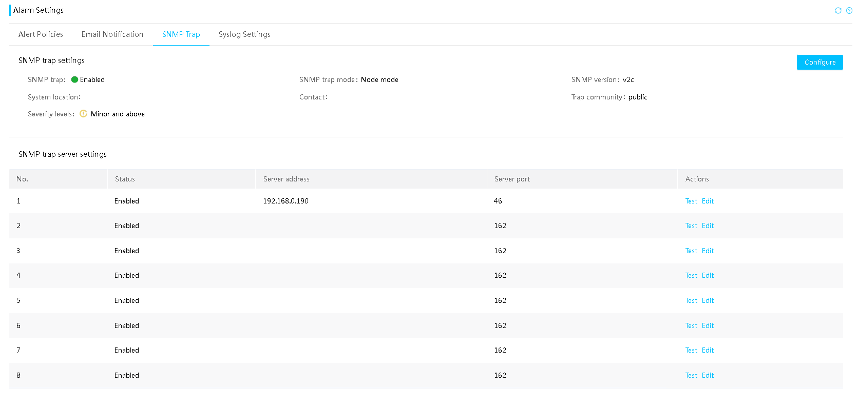
Set up a syslog server
This section uses Red Hat Enterprise Linux 7.7 as an example.
You can set up a Linux syslog server based on UDP, TCP, or TLS.
Set up a Linux syslog server based on UDP or TCP
1. Open the /etc/rsyslog.conf configuration file.
Figure 232 Opening the configuration file
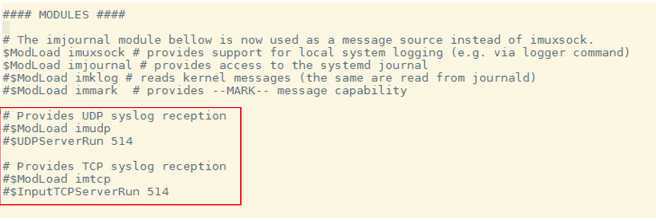
2. Enable UDP and TCP syslog reception.
a. Uncomment the line as shown in Figure 232.
b. Set the UDP server port, TCP server port, or both. If you specify both ports, make sure the specified ports are different. In this example, the UDP port is 514 and the TCP port is 518.
c. Specify the path to store remote logs as /var/log/hdm/messages.log.
Figure 233 Configuring UDP and TCP syslog reception settings
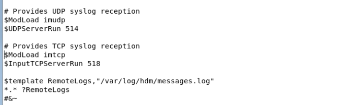
|
|
NOTE: · The $template RemoteLogs directive instructs rsyslog daemon to collect and write all remote messages to distinct files stored in the /var/log directory. · The *.* ?RemoteLogs directive indicates that the RemoteLogs template will be used to receive all log messages. · The & ~ directive instructs rsyslog daemon to stop writing messages to local files, and to write messages only to the messages.log directory. |
3. Execute commands to restart rsyslog and view its status.
Figure 234 Restarting rsyslog and viewing its status
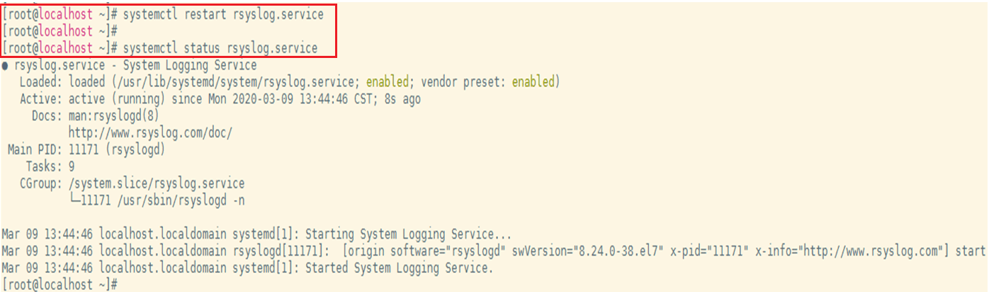
4. Configure syslog settings on the HDM Web interface.
a. Sign in to the HDM Web interface.
b. On the top navigation bar, click O&M Diagnosis.
c. In the left navigation pane, select Alarm Settings.
d. Click the Syslog Settings tab.
e. In the Syslog notification settings section, select Enable for Syslog notification, select host name as the syslog server identifier, select UDP as the transmission protocol, and then click OK.
Figure 235 Configuring syslog notification settings

e. In the Syslog server settings section, click Edit for a syslog server. Configure the syslog server parameters, and then click OK.
Make sure you specify the OS IP address of the server instead of the HDM management address.
Figure 236 Configuring syslog server parameters

Set up a Linux syslog server based on TLS
TLS is an encrypted transmission protocol and supports the following authentication modes.
· One-way authentication—Authenticates only the syslog server.
· Two-way authentication—Authenticates both the syslog server and the client used for HDM login.
Prerequisites
Install the OS on the server. Rsyslog is installed on the OS by default.
Procedure
1. Download the rsyslog-gnutls package for TLS transmission.
¡ If the server is connected to the network, use the sudo yum install -y rsyslog-gnutls or apt command to download the package.
¡ If the server is disconnected from the network, obtain the package from the OS image, as shown in Figure 237.
Figure 237 Obtaining the rsyslog-gnutls package from the OS image
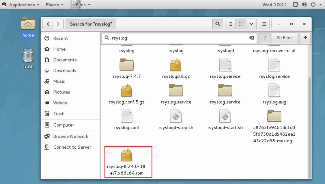
2. Install the rsyslog-gnutls package.
Figure 238 Installing the rsyslog-gnutls package
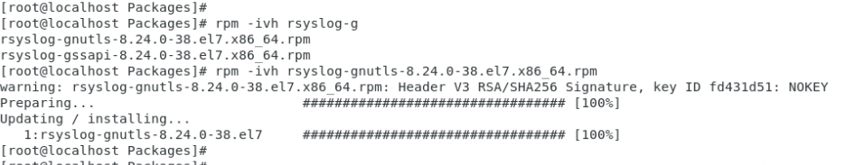
3. Generate a self-signed CA certificate. Right-click on the desktop, select Open Terminal, and then perform the following tasks:
a. Generate a private key file in PEM format.
# cd /root/Desktop
# mkdir tls
# cd tls
# mkdir server
# mkdir client
# openssl genrsa -out cakey.pem 2048
b. Generate a root certificate signing request (CSR) file.
# openssl req -new -key cakey.pem -out ca.csr -subj "/C=CN/ST=myprovice/L=mycity/O=myorganization/OU=mygroup/CN=myCA"
c. Generate a self-signed root certificate.
# openssl x509 -req -days 365 -sha1 -extensions v3_ca -signkey cakey.pem -in ca.csr -out cacert.pem
4. Generate a private key and certificate for the server. Right-click on the desktop, select Open Terminal, and then perform the following tasks:
a. Generate a private key file.
# cd server
# openssl genrsa -out key.pem 2048
b. Generate a certificate request file. This section uses IP address 172.16.18.48 (OS IP address of the server) as an example.
# openssl req -new -key key.pem -out server.csr -subj "/C=CN/ST=myprovice/L=mycity/O=myorganization/OU=mygroup/CN=172.16.18.48"
c. Use the root certificate to issue the server certificate.
# openssl x509 -req -days 365 -sha1 -extensions v3_req -CA ../cacert.pem -CAkey ../cakey.pem -CAserial ca.srl -CAcreateserial -in server.csr -out cert.pem
d. Use the CA certificate to verify the server certificate.
# openssl verify -CAfile ../cacert.pem cert.pem
5. Generate a private key and certificate for the client. Right-click on the desktop, select Open Terminal, and then perform the following tasks:
a. Generate a private key file.
# cd ../client
# openssl genrsa -out key.pem 2048
b. Generate a certificate request file. This section uses IP address 172.16.20.168 as an example.
# openssl req -new -key key.pem -out client.csr -subj "/C=CN/ST=myprovice/L=mycity/O=myorganization/OU=mygroup/CN=172.16.20.168"
c. Use the root certificate to issue the client certificate.
# openssl x509 -req -days 365 -sha1 -extensions v3_req -CA ../cacert.pem -CAkey ../cakey.pem -CAserial ../server/ca.srl -CAcreateserial -in client.csr -out cert.pem
d. Use the CA certificate to verify the client certificate.
# openssl verify -CAfile ../cacert.pem cert.pem
6. Configure the rsyslog.conf configuration file.
a. Leave TCP and UDP settings unchanged, and modify the marked lines as shown in Figure 239.
Figure 239 Configuring the configuration file
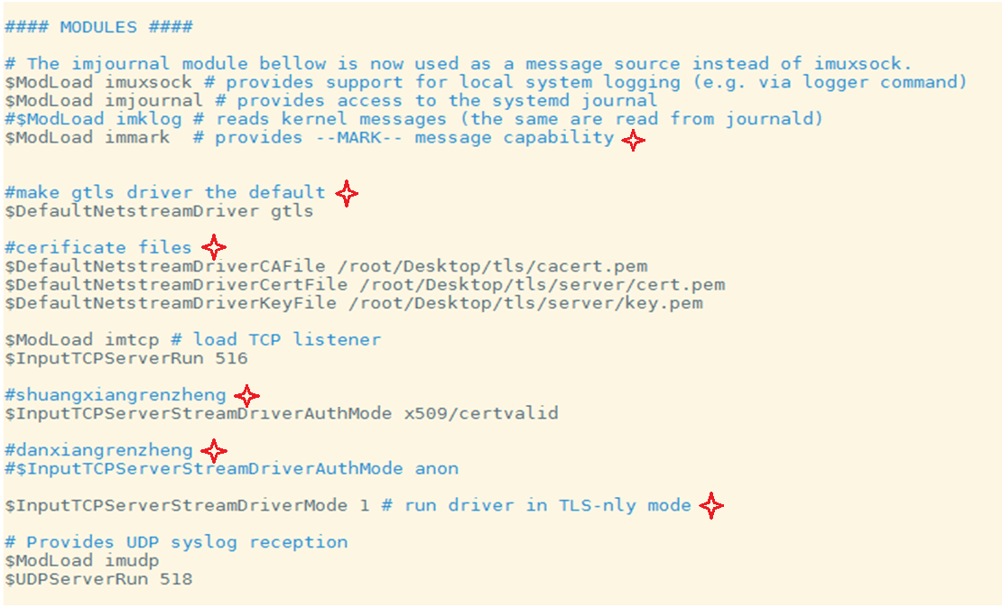
b. Set the server port to 516.
c. For one-way authentication, add the following line to the file:
$InputTCPServerStreamDriverAuthMode anon
d. For two-way authentication, add the following line to the file:
$InputTCPServerStreamDriverAuthMode x509/certvalid
7. Turn off the firewall. Execute the following commands and set SELINUX to disabled:
# systemctl stop firewalld
# setenforce 0
# sed -i 's#SELINUX=enforcing#SELINUX=disabled#g' /etc/selinux/config
8. Restart rsyslog and view its status.
systemctl restart rsyslog
systemctl status rsyslog
9. Configure syslog settings on the HDM Web interface.
a. Copy the certificates generated in steps 3 through 5 to the host used for HDM access.
b. Sign in to HDM.
c. On the top navigation bar, click O&M Diagnosis.
d. In the left navigation pane, select Alarm Settings.
e. Click the Syslog Settings tab.
f. In the Alarm log notification section, enable alarm log notification, select an alarm log host ID and TLS, as shown in Figure 235.
- If you select One-way authentication, upload the self-signed CA certificate generated in step 3.
- If you select Two-way authentication, upload the self-signed CA certificate, local certificate, and private key file generated in steps 3 and 5.
g. Click OK.
Figure 240 Configuring syslog notification settings
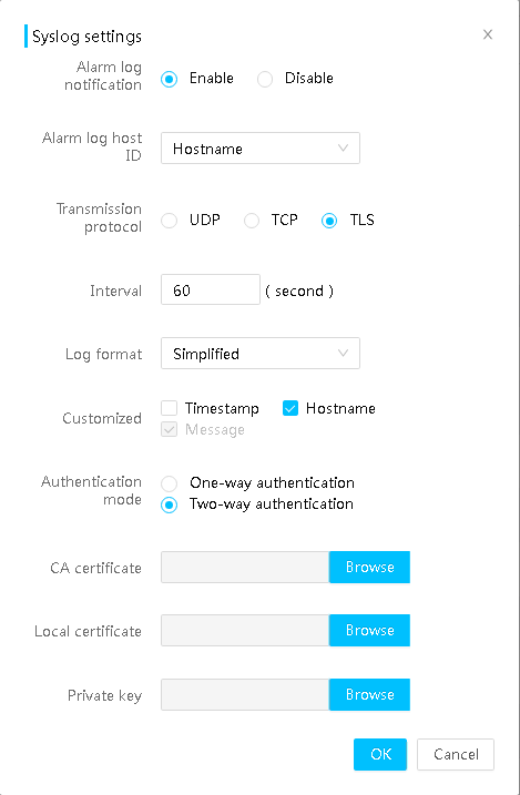
g. Configure the alarm log server parameters, and then click OK.
Figure 241 Configuring alarm log server parameters
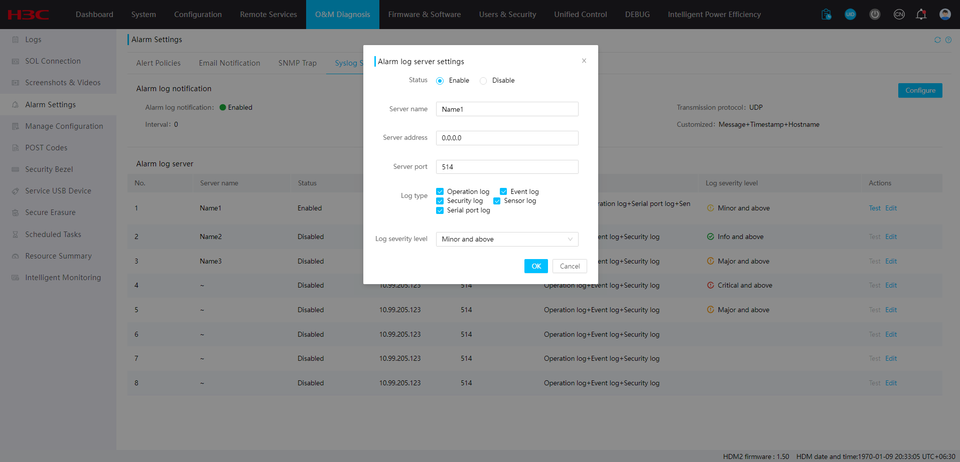
View rsyslog log
1. Log in to the rsyslog server through SSH.
In this example, the IP address of the server is 172.16.18.48.
2. View log entries in the /var/log/hdm/messages.log path.
Figure 242 Viewing rsyslog log
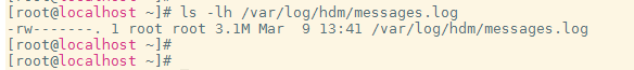
Configure LDAP settings
Lightweight Directory Access Protocol (LDAP) is an application protocol for accessing and maintaining distributed directory information services over an IP network. LDAP can quickly respond to user query requests, and can be used to implement unified user authentication management.
HDM supports both Windows Active Directory and Linux OpenLDAP. This section uses Windows Server 2012 R2 Datacenter as an example to describe LDAP configuration.
Install an OS
Install Windows Server 2012 R2 Datacenter. For more information, see H3C Servers Operating System Installation Guide.
Set up an LDAP server
Prerequisites
Install the OS and access the OS as administrator.
Install a DNS server
2. From the left navigation pane, select Local Server to enter the PROPERTIES page of the local server.
Figure 243 PROPERTIES page of the local server
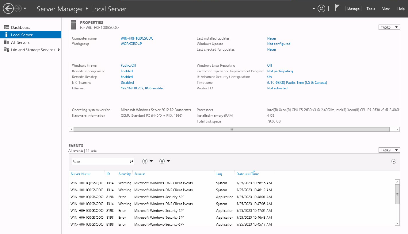
3. Click Manage in the upper right corner and select Add Roles and Features.
4. In the window that opens, click Next.
Figure 244 Add Roles and Features wizard
5. Select Role-based or feature-based installation as the installation type, and then click Next.
Figure 245 Selecting an installation type
6. Select Select a server from the server pool, select the current server as the destination server, and then click Next.
Figure 246 Selecting the destination server
7. Select DNS server as the server role, and then click Next.
Figure 247 Selecting the server role
8. Select NET Framework 4.5 Features, and then click Next.
Figure 248 Selecting the features of the server
9. On the DNS Server tab, click Next.
10. Verify that the server configuration is correct, and then click Install.
Install Active Directory Domain Services on the server
1. Repeat steps 1 to 6 in DNS server installation.
2. On the Server Roles tab, select Active Directory Domain Services, and then click Next.
Figure 249 Selecting the server role

3. Select NET Framework 4.5 Features, and then click Next.
Figure 250 Selecting the features of the server
4. On the AD DS tab, click Next.
5. Verify that the service configuration is correct, and then click Install.
Configure Active Directory Domain Services
1. From the left navigation pane, select AD DS, and then click More....
Figure 251 AD DS menu
2. In the dialog box that opens, click Promote this server to a domain controller in the Action column to open the AD DS configuration wizard.
Figure 252 All Servers Task Details dialog box
3. Select Add a new forest, enter an Active Directory domain name in the Root domain name field, for example, hdmldap, and then click Next.
Figure 253 Active Directory Domain Services configuration wizard
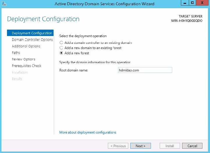
4. On the Domain Controller Options tab, enter the password for the domain controller, and then click Next.
Figure 254 Domain Controller Options menu
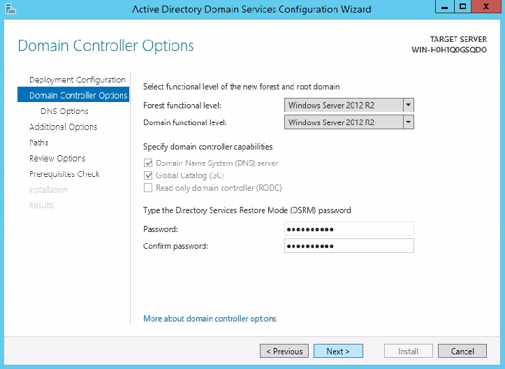
5. Click Next as instructed until you enter the Paths tab. Specify the location of the AD DS database, log files, and SYSVOL, and then click Next.
Figure 255 Configuring Active Directory paths
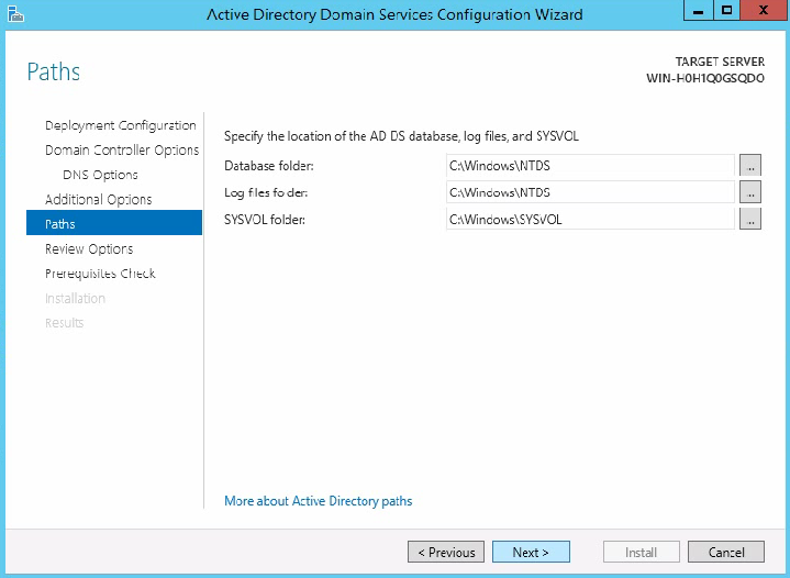
6. Click Next as instructed until you enter the Prerequisites Check tab, and then click Install.
The OS automatically restarts after the installation is complete.
Figure 256 Prerequisites Check menu
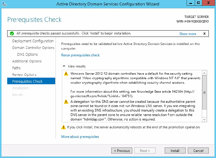
Install Active Directory Certificate Services on the server
1. Access the OS as administrator.
To access the OS successfully, you must add the domain name to the front of the username.
2. Repeat steps 1 to 6 in DNS server installation.
3. On the Server Roles tab, select Active Directory Certificate Services, and then click Next.
Figure 257 Selecting the server role

4. Select NET Framework 4.5 Features, and then click Next.
Figure 258 Selecting the features of the server
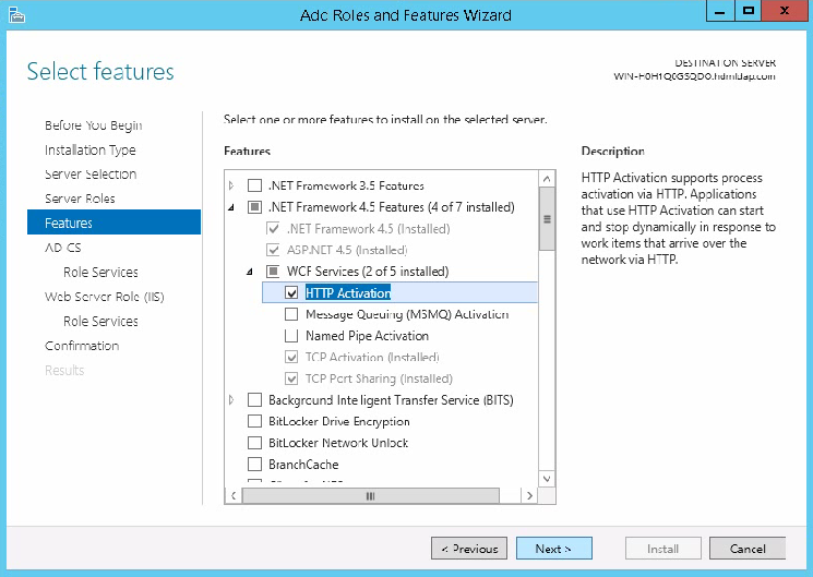
5. On the AD CS tab, click Next.
6. On the Role Services tab, select Certification Authority and Certification Authority Web Enrollment, and then click Next.
Figure 259 Selecting role services for AD CS
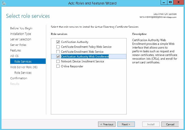
7. On the Web Server Role (IIS) tab, click Next.
8. On the Role Services tab, select role services for the Web server, and then click Next.
As a best practice, use the default role services.
Figure 260 Selecting role services for the Web server

9. On the Confirmation tab, click Install.
Configure Active Directory Certificate Services
1. From the left navigation pane, select AD CS, and then click More....
Figure 261 AD CS menu

2. In the dialog box that opens, click Configure Active Directory Certificate Services on the server in the Action column to open the AD CS configuration wizard.
Figure 262 All Servers Task Details dialog box
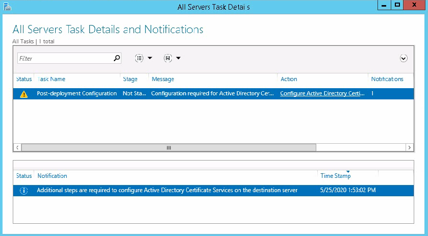
3. On the Credentials tab, click Next.
Figure 263 AD CS configuration wizard
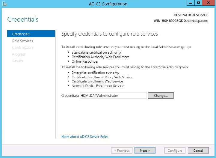
4. On the Role Services tab, select Certificate Authority and Certificate Authority Web Enrollment, and then click Next.
Figure 264 Selecting role services
5. On the Setup Type tab, select Enterprise CA, and then click Next.
6. On the CA Type tab, select Root CA, and then click Next.
7. On the Private Key tab, select Create a new private key, and then click Next.
8. Select RSA as the cryptographic provider, 2048 as the key length, and SHA1 as the hash algorithm, and then click Next.
Figure 265 Specifying the cryptographic options
9. Specify hdmldap-test02 as the CA name, and then click Next.
Figure 266 Specifying the CA name
10. Enter a validity period, and then click Next. The default validity period is 5 years.
11. On the Certificate Database tab, specify the database locations, and then click Next.
Figure 267 Specifying the database locations
12. Verify that the configuration is correct, and then click Configure.
After the configuration is complete, restart the server to make the configuration take effect.
Configure the LDAP server
Prerequisites
After the OS restarts, access the OS as administrator. To access the OS successfully, you must add the domain name to the front of the username.
Create organizational units
LDAP supports levels of organizational units. You can create an organizational unit of any level as needed. This section creates a first-level organizational unit and its second-level units as an example.
To create organizational units:
1. Open Server Manager.
2. Click the Tasks button in the upper right corner, and then select Active Directory Users and Computers.
Figure 268 Active Directory Users and Computers window
3. Right-click hdmldap.com in the left navigation pane, and select New > Organizational Unit.
Figure 269 Right-clicking a domain name
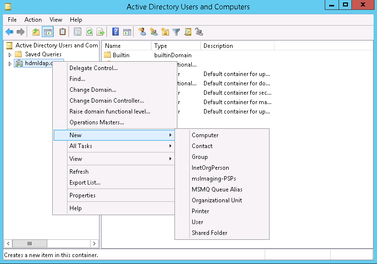
4. In the dialog box that opens, enter an organizational unit name, for example, company, and then click OK.
First-level organizational unit company is created successfully.
Figure 270 Creating a first-level organizational unit
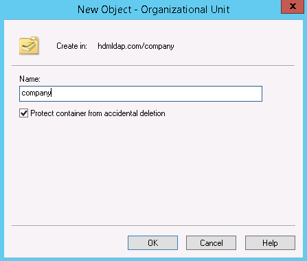
5. To create a second-level organizational unit for the first-level organizational unit, right-click company, and select New > Organizational Unit.
6. In the dialog box that opens, enter an organizational unit name, for example, product, and then click OK.
Second-level organizational unit product is created successfully.
Figure 271 Creating a second-level organizational unit
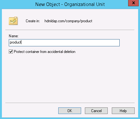
Create a role group
You can create a role group for an organizational unit of any level.
To create a role group:
1. Right-click an organizational unit and select New > Group. This section takes second-level organizational unit product as an example.
2. In the dialog box that opens, enter a group name, for example, group1, select the group scope and group type, and then click OK.
As a best practice, specify the same group name in the Group name (A) and Group name (pre-Windows 2000) fields.
Figure 272 Creating a role group
Creating a user
You can create a user for an organizational unit of any level.
To create a user:
1. Right-click an organizational unit and select New > User. This section takes second-level organizational unit product as an example.
2. In the dialog box that opens, configure the user settings as required, and then click Next.
The usernames in the User logon name and User logon name (pre-Windows 2000) fields will be used for HDM login.
Figure 273 Creating a user
3. Set the password, cancel the User must change password at next logon option, and click Next.
The password will be used for HDM login.
Figure 274 Setting the password
4. Verify that the user configuration is correct, and click Finish.
Add a user to a role group
You can add a user to a role group by configuring the role group or configuring the user. This section configures the user as an example.
To add a user to a user group:
1. Right-click the target user, for example, user1, and select Add to a group.
2. In the dialog box that opens, enter a role group name, for example, group1, and then click OK.
Figure 275 Selecting a role group
Configure LDAP settings from HDM
Configure LDAP settings
1. On the top navigation bar, click Users & Security.
2. In the left navigation pane, select Users.
3. Click the LDAP User tab.
Figure 276 LDAP Users

4. In the LDAP Settings section, click Settings.
5. In the dialog box that opens, enter your login password, enable LDAP authentication, and then configure the following LDAP parameters, as shown in Figure 277:
a. Select No encryption as the encryption type.
b. Select IP as the common name type.
c. Enter the OS IP address of the LDAP server in the Server address field.
d. Use the default port number.
e. Enter the DN information of a user, for example, user1, including the common name, organizational units in ascending order of levels, and the domain names. Separate these parameters with commas.
In this example, enter cn=user1,ou=product,ou=company,dc=hdmldap,dc=com.
f. Enter the password of the user.
g. Enter the domain information of the user in the Search base field.
h. Select cn as the user identification method.
Figure 277 Configuring the LDAP parameters
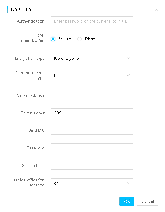
6. Click OK.
Add a role group
1. On the top navigation bar, click Users & Security.
2. In the left navigation pane, select Users.
3. Click the LDAP User tab.
4. In the LDAP Settings section, click Add.
5. Configure the role group parameters, as shown in Figure 278.
6. Click OK.
Figure 278 Adding a role group

Verify the LDAP configuration
Perform this task to verify that the LDAP configuration is complete and has taken effect.
To verify the LDAP configuration:
1. Sign in to HDM with a username and password in role group group1. This section uses user user1 as an example.
Figure 279 Signing in to HDM
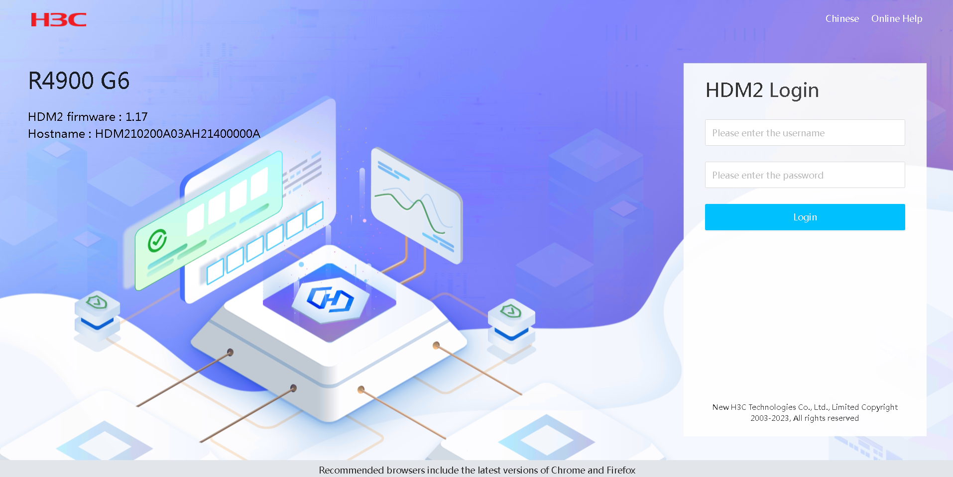
2. View the LDAP settings.
LDAP keywords
|
Keyword |
Full name |
Description |
|
dc |
Domain component |
Domain name. For example, domain name example.com can be translated into dc=example,dc=com. |
|
uid |
User ID |
ID of a user. |
|
ou |
Organizational unit |
Container of Active Directory that can manage Active Directory objects such as users and groups. |
|
cn |
Common name |
N/A |
|
sn |
Surname |
N/A |
|
dn |
Distinguished name |
Distinguished name that uniquely identifies an entry in a directory. |
|
c |
Country |
Country or region code, for example, CN. |
|
o |
Organization |
Organization name. |
Appendix A Downloaded log files
|
Level 1 |
Level 2 |
File name |
Description |
|
dump |
N/A |
dump_end |
Dump end time |
|
HDM_SDS_DUMP_DUP_01 |
Dump encryption information |
||
|
HDM_SDS_DUMP_DUP_02 |
Dump encryption information |
||
|
HDM_SDS_DUMP_DUP_03 |
Dump encryption information |
||
|
HDM_SDS_DUMP_DUP_04 |
Dump encryption information |
||
|
event |
N/A |
*.sbe |
Internal record for event log |
|
*.sme |
Internal record for event log |
||
|
hdm |
N/A |
pack.info |
SDS log compression information |
|
sdmmc0p4 |
log |
auth |
HDM login authentication information |
|
operate |
Operation log |
||
|
update |
Update log |
||
|
visible |
Audit log |
||
|
static |
N/A |
board_cfg |
System board or mainboard information |
|
hdm.json |
HDM configuration |
||
|
bios.json |
BIOS configuration |
||
|
raid.json |
RAID configuration |
||
|
firmware_version |
System firmware version information |
||
|
FruInfo |
FRU information |
||
|
dcpmm_info |
DCPMM information |
||
|
gpu_info |
GPU information |
||
|
hardware.info |
Hardware information |
||
|
hardware_info |
Hardware information |
||
|
net_cfg |
Net configuration |
||
|
PCIe_arguments_table |
PCIe device configuration information |
||
|
nvme_info |
NVMe drive information |
||
|
psu_cfg |
Power configuration |
||
|
sensor_info |
Sensor list |
||
|
test |
SDS log |
