- Table of Contents
-
- 03-WLAN Configuration Guides
- 00-Preface
- 01-AP management configuration
- 02-Radio management configuration
- 03-WLAN access configuration
- 04-WLAN security configuration
- 05-WLAN authentication configuration
- 06-WIPS configuration
- 07-WLAN QoS configuration
- 08-WLAN roaming configuration
- 09-WLAN load balancing configuration
- 10-WLAN radio resource measurement configuration
- 11-Channel scanning configuration
- 12-Band navigation configuration
- 13-WLAN high availability configuration
- 14-Wireless location configuration
- 15-AC hierarchy configuration
- 16-IoT AP configuration
- 17-WLAN probe configuration
- 18-Spectrum management configuration
- 19-WLAN optimization configuration
- 20-WLAN RRM configuration
- 21-WLAN IP snooping configuration
- 22-WLAN radio load balancing configuration
- 23-802.1X client configuration
- 24-IP source guard configuration
- Related Documents
-
| Title | Size | Download |
|---|---|---|
| 22-WLAN radio load balancing configuration | 197.92 KB |
Configuring WLAN radio load balancing
About WLAN radio load balancing
Radio load balancing modes and types
Restrictions and guidelines: WLAN radio load balancing configuration
WLAN radio load balancing tasks at a glance
Prerequisites for WLAN radio load balancing
Enabling WLAN radio load balancing
Configuring radio load balancing parameters
Configuring overloaded 5 GHz radios to hide SSIDs
Enabling band navigation for radio load balancing
Display and maintenance commands for WLAN radio load balancing
WLAN radio load balancing configuration examples
Example: Configuring WLAN radio load balancing
Configuring WLAN radio load balancing
About WLAN radio load balancing
WLAN radio load balancing dynamically balances clients across radios on APs managed by the same AC. It ensures wireless service quality and adequate bandwidth for clients in high-density WLANs.
Networking scheme
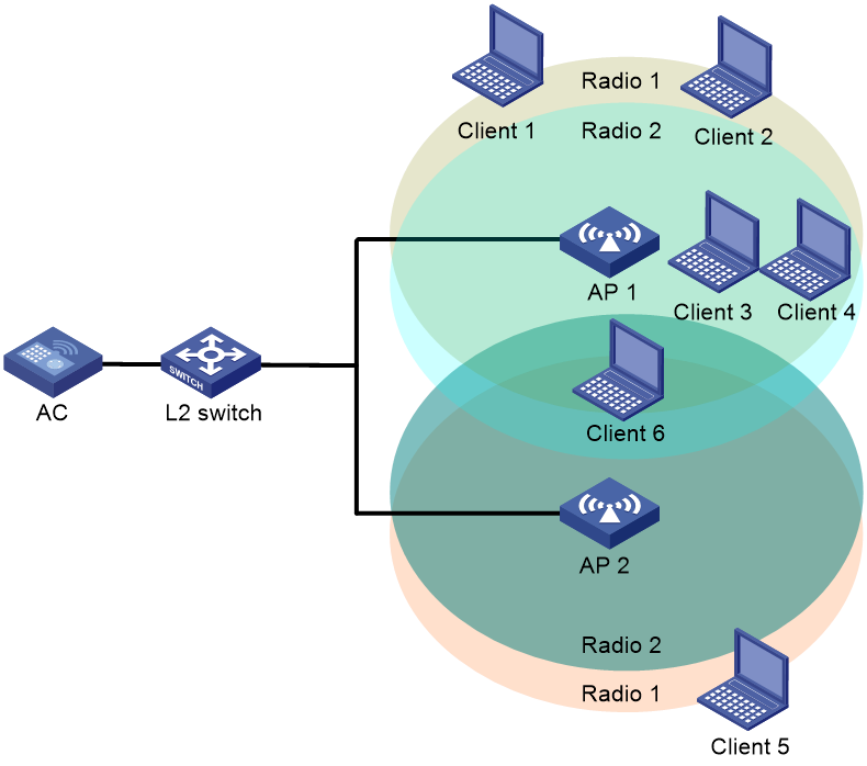
As shown in Figure 1, AP 1 and AP 2 are managed by the same AC and they each have Radio 1 and Radio 2 enabled. Radio load balancing is enabled in the WLAN. Radio 1 and Radio 2 of AP 1 have reached their maximum load. When Client 6 tries to associate with a radio on AP 1, the AC rejects the association request and directs Client 6 to other radios.
Radio load balancing modes and types
The device supports session-mode radio load balancing and the following radio load balancing types:
· Session gap threshold based—The device performs radio load balancing when the following conditions are met:
¡ The number of clients associated with a radio reaches the session threshold.
¡ The session gap between the radio and the radio that has the fewest clients reaches the session gap threshold.
The session gap is the difference between weighted client value of a radio where the client comes online and the weighted client value of the radio that has the fewest clients within the same AC. The weighted client value is equivalent to the number of clients multiplied by the radio weight value. The radio weight values of 2.4 GHz and 5 GHz radios are 2 and 1, respectively.
· Band ratio based—The device performs radio load balancing in the following scenarios:
Scenario 1
¡ A client requests to associate with a 5 GHz radio.
¡ The number of online clients associated with the 5 GHz radio reaches the session threshold.
¡ The ratio between the number of clients associated with all 5 GHz neighbor radios multiplied by the radio weight value and the number of clients associated with all 2.4 GHz neighbor radios multiplied by the radio weight value is larger than the band ratio, or the load of the radio is higher than the average load of all radios of the same type.
Scenario 2
¡ A client requests to associate with a 2.4 GHz radio.
¡ The number of online clients associated with the 2.4 GHz radio reaches the session threshold.
¡ The ratio between the number of clients associated with all 5 GHz neighbor radios multiplied by the radio weight value and the number of clients associated with all 2.4 GHz neighbor radios multiplied by the radio weight value is smaller than or equivalent to the band ratio, or the load of the radio is lower than or equivalent to the average load of all radios of the same type.
|
|
NOTE: Neighbor radios of a client refer to all radios that receive requests from the client. |
Restrictions and guidelines: WLAN radio load balancing configuration
When a client requests to access the WLAN, the system performs radio load balancing only among radios of APs managed by the same AC and can be detected by the client.
WLAN radio load balancing and WLAN load balancing or band navigation are mutually exclusive. For more information about WLAN load balancing and band navigation, see "Configuring WLAN load balancing" and "Configuring band navigation".
WLAN radio load balancing tasks at a glance
To configure WLAN radio load balancing, perform the following tasks:
· (Required.) Enabling WLAN radio load balancing
· (Optional.) Configuring radio load balancing parameters
· (Optional.) Configuring overloaded 5 GHz radios to hide SSIDs
· (Optional.) Enabling band navigation for radio load balancing
Prerequisites for WLAN radio load balancing
Before you configure radio load balancing, make sure the quick association function is disabled. For more information about quick association, see "Enabling quick association".
Enabling WLAN radio load balancing
1. Enter system view.
system-view
2. Enable WLAN radio load balancing.
wlan radio-load-balance enable [ mode session value [ gap gap-value | band-ratio 5g-proportion 2.4g-proportion ] [ report-time time ] ]
By default, WLAN radio load balancing is disabled.
Configuring radio load balancing parameters
About this task
The following parameters affect radio load balancing calculation:
· Radio load balancing RSSI threshold—If a radio detects that the RSSI of a client is lower than the specified RSSI threshold, the radio ignores the association requests of the client.
· Maximum number of denials for association requests—If the number of times that a radio rejects a client reaches the specified maximum number of denials for association requests, the radio accepts the association request of the client.
Procedure
1. Enter system view.
system-view
2. Set the RSSI threshold.
wlan radio-load-balance rssi-threshold rssi-threshold
By default, the RSSI threshold is 30.
3. Set the maximum number of denials for association requests.
wlan radio-load-balance access-denial access-denial
By default, the maximum number of denials is three for association requests.
Configuring overloaded 5 GHz radios to hide SSIDs
About this task
With this feature enabled, a 5 GHz radio hides its SSID in beacon frames when the following conditions are met:
· The number of clients associated with the 5 GHz radio reaches the session threshold.
· The session gap between the 5 GHz radio and another 5 GHz radio on the same AP reaches the session gap threshold.
The 5 GHz radio stops hiding its SSID in beacon frame when either of the following conditions are met:
· The number of clients associated with the 5 GHz radio falls below the session threshold.
· The session gap between the 5 GHz radio and another 5 GHz radio on the same AP falls below the session gap threshold.
Restrictions and guidelines
As a best practice, enable this feature when a large number of clients exist in the network.
This feature takes effect only when an AP has multiple 5 GHz radios.
Procedure
1. Enter system view.
system-view
2. Enter AP view or AP group view.
¡ Enter AP view.
wlan ap ap-name
¡ Enter AP group view.
wlan ap-group group-name
3. Configure overloaded 5 GHz radios to hide SSIDs.
wlan radio-load-balance overload-5g ssid-hide { disable | enable [ session value [ gap gap-value ] ] } [ force-logoff ]
By default:
¡ In AP view, an AP uses the configuration in AP group view.
¡ In AP group view, overloaded 5 GHz radios hide SSIDs.
Enabling band navigation for radio load balancing
About this task
After you enable this feature, the device will send BSS switchover requests to the online 802.11v clients associated with the 2.4 GHz radio. Then, the 802.11v clients can select whether to switch to the 5 GHz radio configured with the 802.11v service.
After you specify the association-reject keyword, the AC rejects 2.4 GHz radio association requests from non-802.11v clients, and navigates the clients to 5 GHz radios. To specify the maximum number of rejections, execute the radio-load-balance band-navigation association-reject command.
Restrictions and guidelines
As a best practice to improve the data transmission performance:
· Use radio-load-balance band-navigation enable when a large number of 802.11v clients are associated with 2.4 GHz radios.
· Use radio-load-balance band-navigation enable association-reject when a large number of non-802.11v clients are associated with 2.4 GHz radios.
To view the number of 802.11v and non-802.11v clients associated with 2.4 GHz radios, execute the display wlan client verbose command.
Procedure
1. Enter system view.
system-view
2. Enter AP view or AP group view.
¡ Enter AP view.
wlan ap ap-name
¡ Enter AP group view.
wlan ap-group group-name
3. Enable band navigation for radio load balancing.
radio-load-balance band-navigation { disable | enable [ association-reject ] }
By default:
¡ In AP view, the AP group configuration is used.
¡ In AP group view, band navigation for radio load balancing is enabled, and association rejection of non-802.11v clients that attempt to access 2.4 GHz radios is disabled.
4. (Optional.) Specify the maximum number of rejections for 2.4 GHz radios against non-802.11v clients.
radio-load-balance band-navigation association-reject 5g-capability 5g-count unknown-capability unknown-count
By default:
In AP view, an AP uses the configuration in AP group view.
In AP group view, a 2.4 GHz radio can reject the association request of a 5 GHz-capable client or unknown client only once.
Display and maintenance commands for WLAN radio load balancing
Execute the display command in any view.
|
Task |
Command |
|
Display radio load balancing information for radios that are bound to a service template. |
display wlan radio-load-balance status service-template template-name client mac-address |
WLAN radio load balancing configuration examples
Example: Configuring WLAN radio load balancing
Network configuration
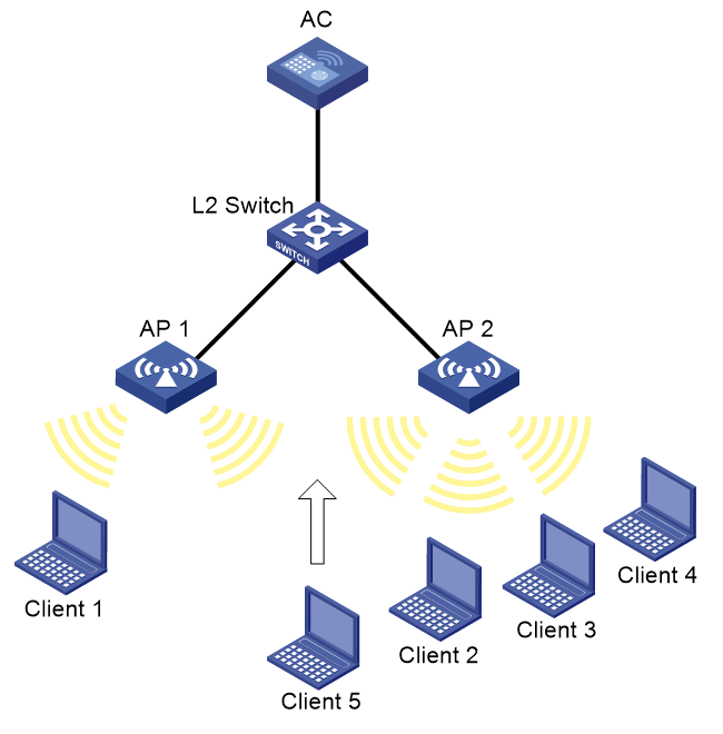
As shown in Figure 2, AP 1 and AP 2 are managed by the AC and the clients can discover the APs. Client 1 associates with AP 1, and Client 2 through Client 4 associate with AP 2.
Configure the AP to perform radio load balancing on radios of AP 1 and AP 2 when the following conditions are met:
· The number of sessions on a radio of an AP reaches 3.
· The session gap between the radio and the radio that has the fewest sessions reaches 2.
Procedure
# Create wireless service template 1, and set its SSID to rlb.
<AC> system-view
[AC] wlan service-template 1
[AC-wlan-st-1] ssid rlb
[AC-wlan-st-1] service-template enable
[AC-wlan-st-1] quit
# Create AP template ap1, and specify the model and serial ID.
[AC] wlan ap ap1 model WA6320
[AC-wlan-ap-ap1] serial-id 219801A28N819CE0002T
# Bind service template 1 to radio 2 of AP 1.
[AC-wlan-ap-ap1] radio 2
[AC-wlan-ap-ap1-radio-2] service-template 1
[AC-wlan-ap-ap1-radio-2] radio enable
[AC-wlan-ap-ap1-radio-2] quit
[AC-wlan-ap-ap1] quit
# Create AP template ap2, and specify the model and serial ID.
[AC] wlan ap ap2 model WA6320
[AC-wlan-ap-ap2] serial-id 219801A28N819CE0002T
# Bind service template 1 to radio 2 of AP 2.
[AC-wlan-ap-ap2] radio 2
[AC-wlan-ap-ap2-radio-2] service-template 1
[AC-wlan-ap-ap2-radio-2] radio enable
[AC-wlan-ap-ap2-radio-2] quit
[AC-wlan-ap-ap2] quit
# Enable WLAN radio load balancing, and set the session threshold and session gap threshold to 3 and 2, respectively.
[AC] wlan radio-load-balance enable mode session 3 gap 2
# Set the RSSI threshold to 30.
[AC] wlan radio-load-balance rssi-threshold 30
# Set the maximum number of denials for association requests to 4.
[AC] wlan radio-load-balance access-denial 4
Verifying the configuration
# Verify that the AC performs radio load balancing on radios of AP 1 and AP 2 when the following conditions are met:
· The number of sessions on radio 2 of AP 2 reaches 3.
· The session gap between radio 2 of AP 2 and radio 2 of AP 1 reaches 2. (Details not shown.)
# Verify that radio 2 on AP 1 and radio 2 on AP 2 are load balanced by using the display wlan client command. (Details not shown.)