- Table of Contents
-
- 07-MPLS Configuration Guide
- 00-Preface
- 01-Basic MPLS configuration
- 02-Static LSP configuration
- 03-LDP configuration
- 04-MPLS TE configuration
- 05-Static CRLSP configuration
- 06-RSVP configuration
- 07-Tunnel policy configuration
- 08-MPLS L3VPN configuration
- 09-IPv6 MPLS L3VPN configuration
- 10-MPLS OAM configuration
- 11-MCE configuration
- Related Documents
-
| Title | Size | Download |
|---|---|---|
| 08-MPLS L3VPN configuration | 2.04 MB |
MPLS L3VPN route advertisement
BGP AS number substitution and SoO attribute
Associating a VPN instance with a Layer 3 interface
Configuring route related attributes for a VPN instance
Configuring routing between a PE and a CE
Configuring static routing between a PE and a CE
Configuring RIP between a PE and a CE
Configuring OSPF between a PE and a CE
Configuring IS-IS between a PE and a CE
Configuring EBGP between a PE and a CE
Configuring IBGP between a PE and a CE
Configuring routing between PEs
Configuring BGP VPNv4 route control
Controlling BGP VPNv4 route advertisement, reception, and saving
Setting a preferred value for received routes
Configuring BGP VPNv4 route reflection
Configuring BGP VPNv4 route attributes
Configuring BGP VPNv4 route filtering
Configuring BGP VPNv4 route dampening
Configuring BGP VPNv4 routes to use private network next hops
Preferring routes learned from the specified peer or peer group during optimal route selection
Advertising BGP RPKI validation state to a peer or peer group
Configuring inter-AS option C (method 1)
Configuring inter-AS option C (method 2)
Specifying the VPN label processing mode on the egress PE
Configuring FRR by using a routing policy
Enabling MPLS L3VPN FRR for an address family
Configuring a TTL processing mode for tunnels associated with a VPN instance
Redistributing the loopback interface address
Configuring BGP AS number substitution and SoO attribute
Configuring the BGP additional path feature
Configuring link bandwidth attributes for BGP VPNv4 routes
Enabling independent routing tables for BGP VPNv4 routes and BGP-VPN instance routes
Minimizing the priority of BGP routes advertised to peers
Minimizing the priority of BGP routes advertised to peers with a down-to-up state change
Minimizing the priority of BGP routes advertised to peers after a device reboot
Restoring the priority of advertised BGP routes
Specifying a local network to be advertised in the public instance or a VPN instance
Configuring the public instance
Configuring route replication for public and VPN instances
Configuring BGP route replication between public and VPN instances
Configuring route re-origination
Enabling a VPN instance to use the public instance routing table for packet forwarding
Enabling ECMP VPN route redistribution
Enabling prioritized withdrawal of specific routes
Configuring BGP next hop recursion based on a routing policy
Enabling SNMP notifications for MPLS L3VPN
Enabling logging for BGP route flapping
Verifying and maintaining MPLS L3VPN
Verifying MPLS L3VPN configuration and running status
Displaying and clearing BGP VPNv4 route dampening parameters
Displaying and clearing BGP VPNv4 route flapping statistics
MPLS L3VPN configuration examples
Example: Configuring basic MPLS L3VPN
Example: Configuring a hub-spoke network
Example: Configuring MPLS L3VPN inter-AS option A
Example: Configuring MPLS L3VPN inter-AS option B
Example: Configuring MPLS L3VPN inter-AS option C (method 1)
Example: Configuring MPLS L3VPN inter-AS option C (method 2)
Example: Configuring MPLS L3VPN carrier's carrier in the same AS
Example: Configuring MPLS L3VPN carrier's carrier in different ASs
Example: Configuring nested VPN
Example: Configuring an OSPF sham link
Example: Configuring BGP AS number substitution
Example: Configuring BGP AS number substitution and SoO attribute
Example: Configuring MPLS L3VPN FRR through VPNv4 route backup for a VPNv4 route
Example: Configuring MPLS L3VPN FRR through VPNv4 route backup for an IPv4 route
Example: Configuring MPLS L3VPN FRR through IPv4 route backup for a VPNv4 route
Configuring MPLS L3VPN
About MPLS L3VPN
MPLS L3VPN is a L3VPN technology used to interconnect geographically dispersed VPN sites. MPLS L3VPN uses BGP to advertise VPN routes and uses MPLS to forward VPN packets over a service provider backbone. MPLS L3VPN provides flexible networking modes, excellent scalability, and convenient support for MPLS QoS and MPLS TE.
Basic MPLS L3VPN architecture
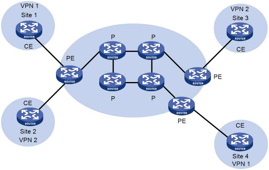
As shown in Figure 1, a basic MPLS L3VPN architecture has the following types of devices:
· Customer edge device—A CE device resides on a customer network and has one or more interfaces directly connected to a service provider network. It does not support MPLS.
· Provider edge device—A PE device resides at the edge of a service provider network and is connected to one or more CEs. All MPLS VPN services are processed on PEs.
· Provider device—A P device is a core device on a service provider network. It is not directly connected to any CEs. A P device has only basic MPLS forwarding capability and does not handle VPN routing information.
Figure 1 Basic MPLS L3VPN architecture
MPLS L3VPN concepts
Site
A site has the following features:
· A site is a group of IP systems with IP connectivity that does not rely on any service provider networks.
· The classification of a site depends on the topology relationship of the devices, rather than the geographical positions. However, the devices at a site are, in most cases, adjacent to each other geographically.
· The devices at a site can belong to multiple VPNs, which means that a site can belong to multiple VPNs.
· A site is connected to a provider network through one or more CEs. A site can contain multiple CEs, but a CE can belong to only one site.
Sites connected to the same provider network can be classified into different sets by policies. Only the sites in the same set can access each other through the provider network. Such a set is called a VPN.
VPN instance
VPN instances implement route isolation, data independence, and data security for VPNs.
A VPN instance has the following components:
· A separate Label Forwarding Information Base (LFIB).
· An IP routing table.
· Interfaces bound to the VPN instance.
· VPN instance administration information, including route distinguishers (RDs), route targets (RTs), and route filtering policies.
To associate a site with a VPN instance, bind the VPN instance to the PE's interface connected to the site. A site can be associated with only one VPN instance, and different sites can be associated with the same VPN instance. A VPN instance contains the VPN membership and routing rules of associated sites.
VPN-IPv4 address
Each VPN independently manages its address space. The address spaces of VPNs might overlap. For example, if both VPN 1 and VPN 2 use the addresses on subnet 10.110.10.0/24, address space overlapping occurs.
BGP cannot process overlapping VPN address spaces. For example, if both VPN 1 and VPN 2 use the subnet 10.110.10.0/24 and each advertise a route destined for the subnet, BGP selects only one of them. This results in the loss of the other route.
Multiprotocol BGP (MP-BGP) can solve this problem by advertising VPN-IPv4 addresses (also called VPNv4 addresses).
Figure 2 VPN-IPv4 address structure
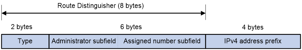
As shown in Figure 2, a VPN-IPv4 address consists of 12 bytes. The first eight bytes represent the RD, followed by a four-byte IPv4 prefix. The RD and the IPv4 prefix form a unique VPN-IPv4 prefix.
An RD can be in one of the following formats:
· When the Type field is 0, the Administrator subfield occupies two bytes, the Assigned number subfield occupies four bytes, and the RD format is 16-bit AS number:32-bit user-defined number. For example, 100:1.
· When the Type field is 1, the Administrator subfield occupies four bytes, the Assigned number subfield occupies two bytes, and the RD format is 32-bit IPv4 address:16-bit user-defined number. For example, 172.1.1.1:1.
· When the Type field is 2, the Administrator subfield occupies four bytes, the Assigned number subfield occupies two bytes, and the RD format is 32-bit AS number:16-bit user-defined number, where the minimum value of the AS number is 65536. For example, 65536:1.
To guarantee global uniqueness for a VPN-IPv4 address, do not set the Administrator subfield to any private AS number or private IP address.
Route target attribute
MPLS L3VPN uses route target (also called VPN target) community attributes to control the advertisement of VPN routing information. A VPN instance on a PE supports the following types of route target attributes:
· Export target attribute—A PE sets the export target attribute for VPN-IPv4 routes learned from directly connected sites before advertising them to other PEs.
· Import target attribute—A PE checks the export target attribute of VPN-IPv4 routes received from other PEs. If the export target attribute matches the import target attribute of a VPN instance, the PE adds the routes to the routing table of the VPN instance.
Route target attributes define which sites can receive VPN-IPv4 routes, and from which sites a PE can receive routes.
Like RDs, route target attributes can be one of the following formats:
· 16-bit AS number:32-bit user-defined number. For example, 100:1.
· 32-bit IPv4 address:16-bit user-defined number. For example, 172.1.1.1:1.
· 32-bit AS number:16-bit user-defined number, where the minimum value of the AS number is 65536. For example, 65536:1.
MP-BGP
MP-BGP supports multiple address families, including VPN-IPv4 address family.
In MPLS L3VPN, MP-BGP advertises VPN-IPv4 routes for VPN sites between PEs.
MPLS L3VPN route advertisement
In a basic MPLS L3VPN, CEs and PEs are responsible for advertising VPN routing information. P routers maintain only the routes within the backbone. A PE maintains only routing information for directly connected VPNs, rather than for all VPNs.
VPN routing information is advertised through the path local CE—ingress PE—egress PE—remote CE.
Route advertisement from the local CE to the ingress PE
The CE advertises standard IPv4 routing information to the ingress PE over a static route, RIP route, OSPF route, IS-IS route, EBGP route, or IBGP route.
Route advertisement from the ingress PE to the egress PE
The ingress PE performs the following operations:
1. Adds RDs and route target attributes to these standard IPv4 routes to create VPN-IPv4 routes.
2. Saves the VPN-IPv4 routes to the routing table of the VPN instance created for the CE.
3. Advertises the VPN-IPv4 routes to the egress PE through MP-BGP.
Route advertisement from the egress PE to the remote CE
After receiving the VPN-IPv4 routes, the egress PE performs the following operations:
1. Compares the routes' export target attributes with the local import target attributes.
2. Adds the routes to the routing table of the VPN instance if the export and local import target attributes match each other.
3. Restores the VPN-IPv4 routes to the original IPv4 routes.
4. Advertises those routes to the connected CE over a static route, RIP route, OSPF route, IS-IS route, EBGP route, or IBGP route.
MPLS L3VPN packet forwarding
In a basic MPLS L3VPN (within a single AS), a PE adds the following information into VPN packets:
· Outer tag—Identifies the public tunnel from the local PE to the remote PE. The public tunnel can be an LSP or an MPLS TE tunnel. Based on the outer tag, a VPN packet can be forwarded along the public tunnel to the remote PE. The outer tag is an MPLS label.
· Inner label—Identifies the remote VPN site. The remote PE uses the inner label to forward packets to the target VPN site. MP-BGP advertises inner labels for VPN-IPv4 routes among PEs.
Figure 3 VPN packet forwarding
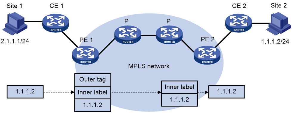
As shown in Figure 3, a VPN packet is forwarded from Site 1 to Site 2 by using the following process:
1. Site 1 sends an IP packet with the destination address 1.1.1.2. CE 1 transmits the packet to PE 1.
2. PE 1 performs the following operations:
a. Finds the matching VPN route based on the inbound interface and destination address of the packet.
b. Labels the packet with both the inner label and the outer tag.
c. Forwards the packet to the public tunnel.
3. P devices forward the packet to PE 2 by the outer tag. The label is removed from the packet at the penultimate hop.
4. PE 2 performs the following operations:
a. Uses the inner label to find the matching VPN instance to which the destination address of the packet belongs.
b. Looks up the routing table of the VPN instance for the output interface.
c. Removes the inner label and forwards the packet out of the interface to CE 2.
5. CE 2 transmits the packet to the destination through IP forwarding.
When two sites of a VPN are connected to the same PE, the PE directly forwards packets between the two sites through the VPN routing table without adding any tag or label.
MPLS L3VPN networking schemes
In MPLS L3VPNs, route target attributes are used to control the advertisement and reception of VPN routes between sites. They work independently and can be configured with multiple values to support flexible VPN access control and implement multiple types of VPN networking schemes.
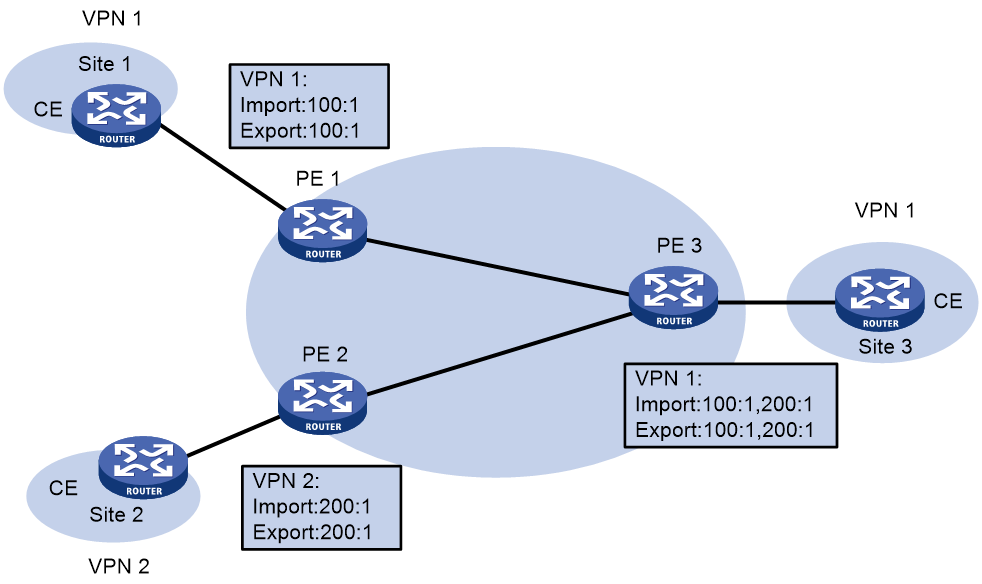
Basic VPN networking scheme
In the simplest case, all users in a VPN form a closed user group. They can forward traffic to each other but cannot communicate with any user outside the VPN.
For the basic VPN networking scheme, you must assign a route target to each VPN for identifying the export target attribute and import target attribute of the VPN. Moreover, this route target cannot be used by any other VPNs.
Figure 4 Network diagram for basic VPN networking scheme
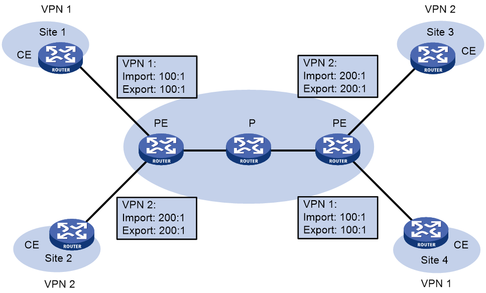
As shown in Figure 4, the route target for VPN 1 is 100:1, while that for VPN 2 is 200:1. The two VPN 1 sites can communicate with each other, and the two VPN 2 sites can communicate with each other. However, the VPN 1 sites cannot communicate with the VPN 2 sites.
Hub and spoke networking scheme
The hub and spoke networking scheme is suitable for a VPN where all users must communicate with each other through an access control device.
In a hub and spoke network as shown in Figure 5, configure route targets as follows:
· On spoke PEs (PEs connected to spoke sites), set the export target to Spoke and the import target to Hub.
· On the hub PE (PE connected to the hub site), use two interfaces that each belong to a different VPN instance to connect the hub CE. One VPN instance receives routes from spoke PEs and has the import target set to Spoke. The other VPN instance advertises routes to spoke PEs and has the export target set to Hub.
These route targets rules produce the following results:
· The hub PE can receive all VPN-IPv4 routes from spoke PEs.
· All spoke PEs can receive VPN-IPv4 routes advertised by the hub PE.
· The hub PE advertises the routes learned from a spoke PE to the other spoke PEs so the spoke sites can communicate with each other through the hub site.
· The import target attribute of a spoke PE is different from the export target attribute of any other spoke PE. Any two spoke PEs do not directly advertise VPN-IPv4 routes to each other. Therefore, they cannot directly access each other.
Figure 5 Network diagram for hub and spoke network
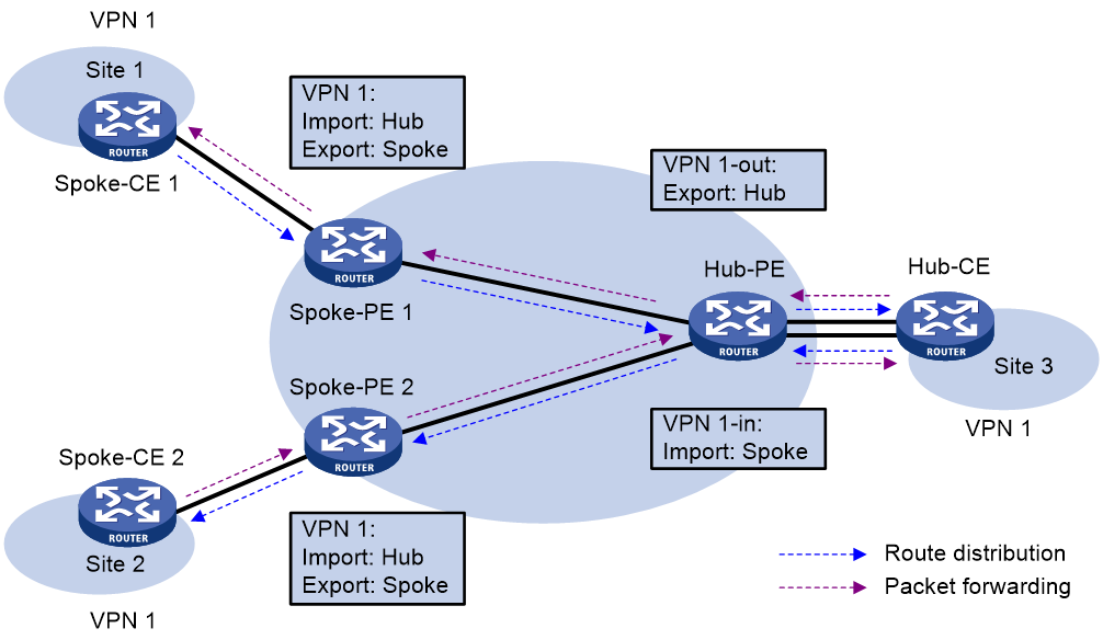
A route in Site 1 is advertised to Site 2 by using the following process:
1. Spoke-CE 1 advertises a route in Site 1 to Spoke-PE 1.
2. Spoke-PE 1 changes the route to a VPN-IPv4 route and advertises the VPN-IPv4 route to Hub-PE through MP-BGP.
3. Hub-PE adds the VPN-IPv4 route into the routing table of VPN 1-in, changes it to the original IPv4 route, and advertises the IPv4 route to Hub-CE.
4. Hub-CE advertises the IPv4 route back to Hub-PE.
5. Hub-PE adds the IPv4 route to the routing table of VPN 1-out, changes it to a VPN-IPv4 route, and advertises the VPN-IPv4 route to Spoke-PE 2 through MP-BGP.
6. Spoke-PE 2 changes the VPN-IPv4 route to the original IPv4 route, and advertises the IPv4 route to Site 2.
After spoke sites exchange routes through the hub site, they can communicate with each other through the hub site.
Extranet networking scheme
The extranet networking scheme allows specific resources in a VPN to be accessed by users not in the VPN.
In this networking scheme, if a VPN instance needs to access a shared site, the export target attribute and the import target attribute of the VPN instance must be contained in the import target attribute and the export target attribute of the VPN instance of the shared site, respectively.
Figure 6 Network diagram for extranet networking scheme
As shown in Figure 6, route targets configured on PEs produce the following results:
· PE 3 can receive VPN-IPv4 routes from PE 1 and PE 2.
· PE 1 and PE 2 can receive VPN-IPv4 routes advertised by PE 3.
· Site 1 and Site 3 of VPN 1 can communicate with each other, and Site 2 of VPN 2 and Site 3 of VPN 1 can communicate with each other.
· PE 3 advertises neither the VPN-IPv4 routes received from PE 1 to PE 2 nor the VPN-IPv4 routes received from PE 2 to PE 1 (routes learned from an IBGP neighbor are not advertised to any other IBGP neighbor). Therefore, Site 1 of VPN 1 and Site 2 of VPN 2 cannot communicate with each other.
Inter-AS VPN
In an inter-AS VPN networking scenario, multiple sites of a VPN are connected to multiple ISPs in different ASs, or to multiple ASs of an ISP.
Inter AS-VPN provides the following solutions:
· VRF-to-VRF connections between ASBRs—This solution is also called inter-AS option A.
· EBGP redistribution of labeled VPN-IPv4 routes between ASBRs—ASBRs advertise VPN-IPv4 routes to each other through MP-EBGP. This solution is also called inter-AS option B.
· Multihop EBGP redistribution of labeled VPN-IPv4 routes between PE routers—PEs advertise VPN-IPv4 routes to each other through MP-EBGP. This solution is also called inter-AS option C.
Inter-AS option A
In this solution, PEs of two ASs are directly connected, and each PE is also the ASBR of its AS. Each PE treats the other as a CE and advertises unlabeled IPv4 unicast routes through EBGP. The PEs associate a VPN instance with a minimum of one interface.
Figure 7 Network diagram for inter-AS option A
As shown in Figure 7, in VPN 1, routes are advertised from CE 1 to CE 3 by using the following process:
1. PE 1 advertises the VPN routes learned from CE 1 to ASBR 1 through MP-IBGP.
2. ASBR 1 performs the following operations:
a. Adds the routes to the routing table of the VPN instance whose import target attribute matches the export target attribute of the routes.
b. Advertises the routes as IPv4 unicast routes to its CE (ASBR 2) through EBGP.
3. ASBR 2 adds the IPv4 unicast routes to the routing table of the VPN instance that is bound to the receiving interface, and advertises the routes to PE 3 through MP-IBGP.
4. PE 3 advertises the received routes to CE 3.
Packets forwarded within an AS are VPN packets that carry two labels. Packets forwarded between ASBRs are common IP packets.
Inter-AS option A is easy to carry out because no special configuration is required on the PEs acting as the ASBRs.
However, it has limited scalability because the PEs acting as the ASBRs must manage all the VPN routes and create VPN instances on a per-VPN basis. This leads to excessive VPN-IPv4 routes on the PEs. Associating a separate interface with each VPN also requires additional system resources.
Inter-AS option B
In this solution, two ASBRs use MP-EBGP to exchange VPN-IPv4 routes that they obtain from the PEs in their respective ASs.
Figure 8 Network diagram for inter-AS option B
As shown in Figure 8, in VPN 1, routes are advertised from CE 1 to CE 3 by using the following process:
1. PE 1 advertises the VPN routes learned from CE 1 to ASBR 1 through MP-IBGP.
Assume that the inner label assigned by PE 1 for the routes is L1.
2. ASBR 1 advertises the VPN-IPv4 routes to ASBR 2 through MP-EBGP.
Before advertising the routes, ASBR 1 modifies the next hop as its own address, assigns a new inner label (L2) to the routes, and associates L1 with L2.
3. ASBR 2 advertises the VPN-IPv4 routes to PE 3 through MP-IBGP.
Before advertising the routes, ASBR 2 modifies the next hop as its own address, assigns a new inner label (L3) to the routes, and associates L2 with L3.
4. PE 3 advertises the received routes to CE 3.
A packet is forwarded from CE 3 to CE 1 by using the following process:
5. PE 3 encapsulates the received packet with two labels, and forwards the encapsulated packet to ASBR 2.
One of the labels is L3, and the other is the outer tag for the public tunnel from PE 3 to ASBR 2.
6. ASBR 2 removes the outer tag, replaces L3 with L2, and forwards the packet to ASBR 1.
Packets between ASBR 1 and ASBR 2 carry only one inner label.
7. ASBR 1 replaces L2 with L1, adds the outer tag of the public tunnel from ASBR 1 to PE 1, and forwards the packet to PE 1.
8. PE 1 removes the inner label and outer tag and forwards the packet to CE 1.
In this solution, ASBRs must receive all inter-AS VPN routes. Therefore, ASBRs cannot filter incoming VPN-IPv4 routes by route targets.
Inter-AS option B has better scalability than option A. However, it requires that ASBRs maintain and advertise VPN routes.
Inter-AS option C
The Inter-AS option A and option B solutions require that the ASBRs maintain and advertise VPN-IPv4 routes. When every AS needs to exchange a great amount of VPN routes, the ASBRs might become bottlenecks, which hinders network extension. Inter-AS option C has better scalability because it makes PEs directly exchange VPN-IPv4 routes.
In this solution, PEs exchange VPN-IPv4 routes over a multihop MP-EBGP session. Each PE must have a route to the peer PE and a label for the route so that the inter-AS public tunnel between the PEs can be set up. Inter-AS option C sets up a public tunnel by using the following methods:
· Method 1:
a. The PE and the ASBR within an AS establish a public tunnel by using a label distribution protocol such as LDP.
b. The local and remote ASBRs advertise labeled IPv4 unicast routes through BGP to establish an inter-AS public tunnel.
Labeled IPv4 unicast route advertisement refers to the process of assigning MPLS labels to IPv4 unicast routes and advertising IPv4 unicast routes and their labels.
· Method 2:
In method 2, the PE and ASBR within an AS do not need to establish an IBGP peer relationship.
a. The local ASBR redistributes IGP routes to the BGP routing table, assigns labels to the routes, and advertises the labeled routes to the remote ASBR.
b. The remote ASBR redistributes BGP routes to the IGP routing table.
c. The local and remote PEs then can learn the route s to reach each other. After the PEs learn the routes to each other, they establish a public tunnel by using a label distribution protocol such as LDP.
The following is an example of configuring inter-AS option C by using method 1.
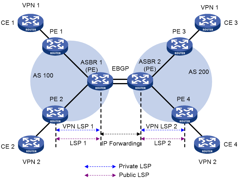
Figure 9 Network diagram for inter-AS option C (method 1)
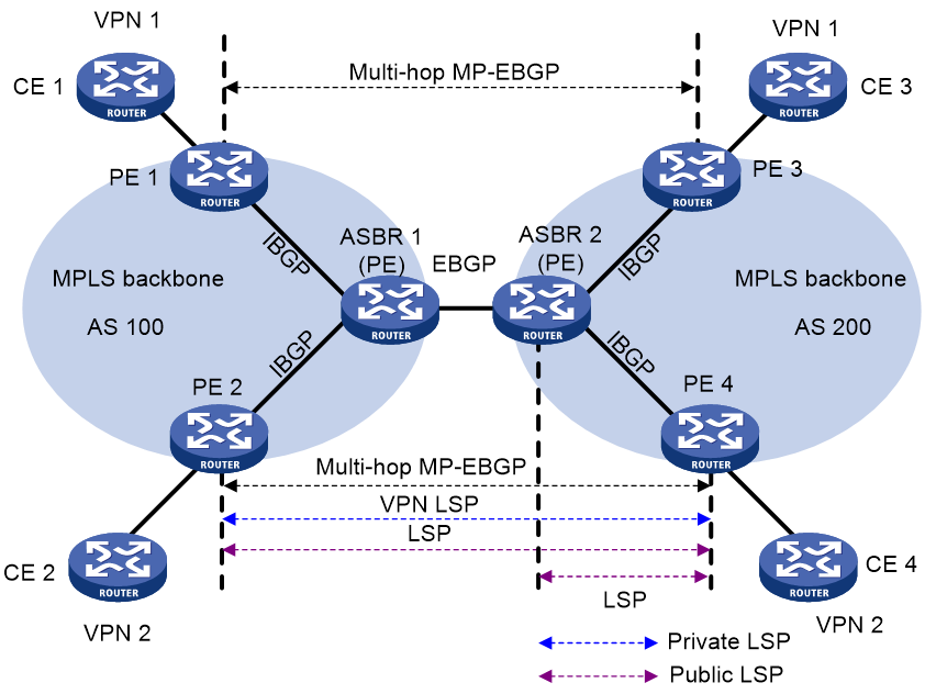
As shown in Figure 9, in VPN 1, routes are advertised from CE 1 to CE 3 by using the following process:
2. PE 1 advertises the VPN routes learned from CE 1 as VPN-IPv4 routes to PE 3 through multihop MP-EBGP.
Assume that the inner label assigned by PE 1 for the routes is Lx.
3. PE 3 advertises the received routes to CE 3.
Setting up an inter-AS public tunnel is difficult in this solution. A public tunnel, for example, the one from PE 3 to PE 1, is set up by using the following process:
4. Within AS 100, the public tunnel from ASBR 1 to PE 1 is set up by using a label distribution protocol, for example, LDP.
Assume that the outgoing label for the public tunnel on ASBR 1 is L1.
5. ASBR 1 advertises labeled IPv4 unicast routes to ASBR 2 through EBGP.
The route destined for PE 1 and the label (L2) assigned by ASBR 1 for the route are advertised from ASBR 1 to ASBR 2. The next hop of the route is ASBR 1. The public tunnel from ASBR 2 to ASBR 1 is set up. The incoming label for the public tunnel on ASBR 1 is L2.
6. ASBR 2 advertises labeled IPv4 unicast routes to PE 3 through IBGP.
The route destined for PE 1 and the label (L3) assigned by ASBR 2 for the route are advertised from ASBR 2 to PE 3. The next hop for the route is ASBR 2. The public tunnel from PE 3 to ASBR 2 is set up. The incoming label for the public tunnel on ASBR 2 is L3, and the outgoing label is L2.
7. MPLS packets cannot be forwarded directly from PE 3 to ASBR 2. Within AS 200, the public tunnel from PE 3 to ASBR 2 is required to be set up hop by hop through a label distribution protocol, for example, LDP.
Assume that the outgoing label for the public tunnel on PE 3 is Lv.
After route advertisement and public tunnel setup, a packet is forwarded from CE 3 to CE 1 by using the following process:
1. PE 3 performs the following routing table lookups for the packet:
a. Finds a matching route with next hop PE 1 and inner label Lx, and encapsulates the packet with label Lx.
b. Finds the route to PE 1 with next hop ASBR 2 and label L3, and encapsulates the packet with label L3 as the outer label.
c. Finds the route to ASBR 2 with outgoing label Lv, and encapsulates the packet with label Lv as the outmost label.
2. AS 200 transmits the packet to ASBR 2 by the outmost label.
3. ASBR 2 removes the outmost label, replaces L3 with L2, and forwards the packet to ASBR 1.
4. ASBR 1 replaces L2 with L1, and forwards the packet.
5. AS 100 transmits the packet to PE 1 by the outer label.
6. PE 1 removes the outer label, and forwards the packet to CE 1 according to the inner label Lx.
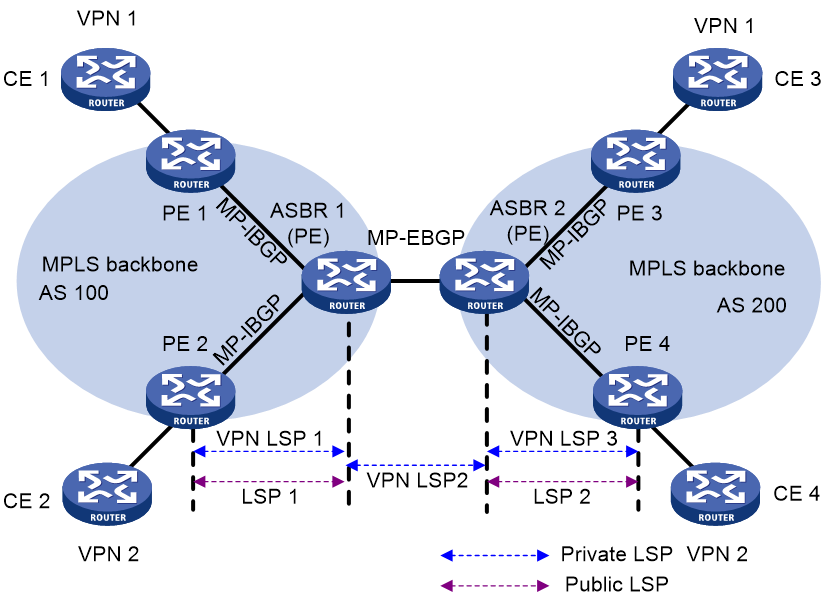
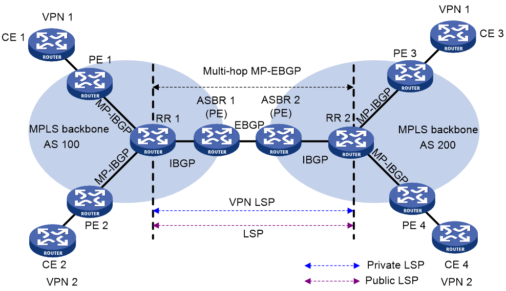
As shown in Figure 10, to improve scalability, you can specify a route reflector (RR) in each AS to exchange VPN-IPv4 routes with PEs in the same AS. The RR in each AS maintains all VPN-IPv4 routes. The RRs in two ASs establish a multihop MP-EBGP session to advertise VPN-IPv4 routes.
Figure 10 Network diagram for inter-AS option C using RRs
Carrier's carrier
If a customer of an MPLS L3VPN service provider is also a service provider:
· The MPLS L3VPN service provider is called the provider carrier or the Level 1 carrier.
· The customer is called the customer carrier or the Level 2 carrier.
This networking model is referred to as carrier's carrier.
The PEs of the Level 2 carrier directly exchange customer networks over a BGP session. The Level 1 carrier only learns the backbone networks of the Level 2 carrier, without learning customer networks.
For packets between customer networks to travel through the Level 1 carrier, the PE of the Level 1 carrier and the CE of the Level 2 carrier must assign labels to the backbone networks of the Level 2 carrier. The CE of the Level 2 carrier is a PE within the Level 2 carrier network.
Follow these guidelines to assign labels:
· If the PE and the CE are in the same AS, you must configure IGP and LDP between them. If they are in different ASs, you must configure MP-EBGP to assign labels to IPv4 unicast routes exchanged between them.
· You must enable MPLS on the CE of the Level 2 carrier regardless of whether the PE and CE are in the same AS.
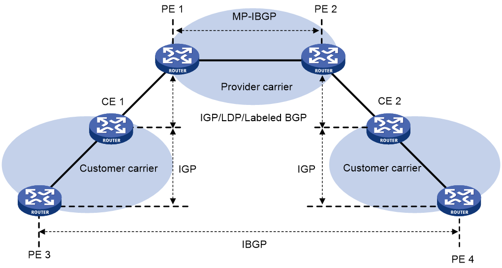
A Level 2 carrier can be an ordinary ISP or an MPLS L3VPN service provider.
As shown in Figure 11, when the customer carrier is an ordinary ISP, its PEs and CEs run IGP to communicate with each other. The PEs do not need to run MPLS. PE 3 and PE 4 exchange customer network routes (IPv4 unicast routes) through an IBGP session.
Figure 11 Scenario where the Level 2 carrier is an ISP
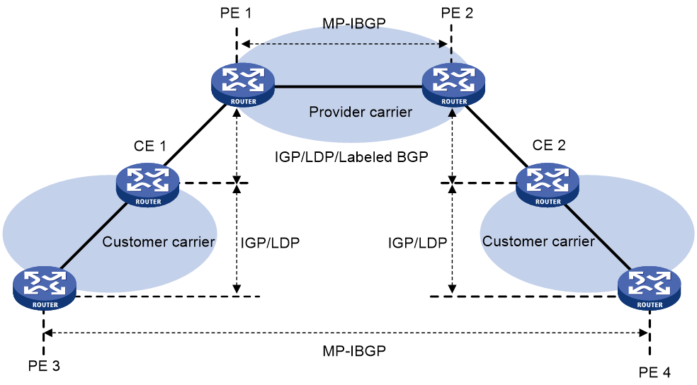
As shown in Figure 12, when the customer carrier is an MPLS L3VPN service provider, its PEs and CEs must run IGP and LDP to communicate with each other. PE 3 and PE 4 exchange customer network routes (VPN-IPv4 routes) through an MP-IBGP session.
Figure 12 Scenario where the Level 2 carrier is an MPLS L3VPN service provider
|
|
NOTE: As a best practice, establish equal cost LSPs between the Level 1 carrier and the Level 2 carrier if equal cost routes exist between them. |
Nested VPN
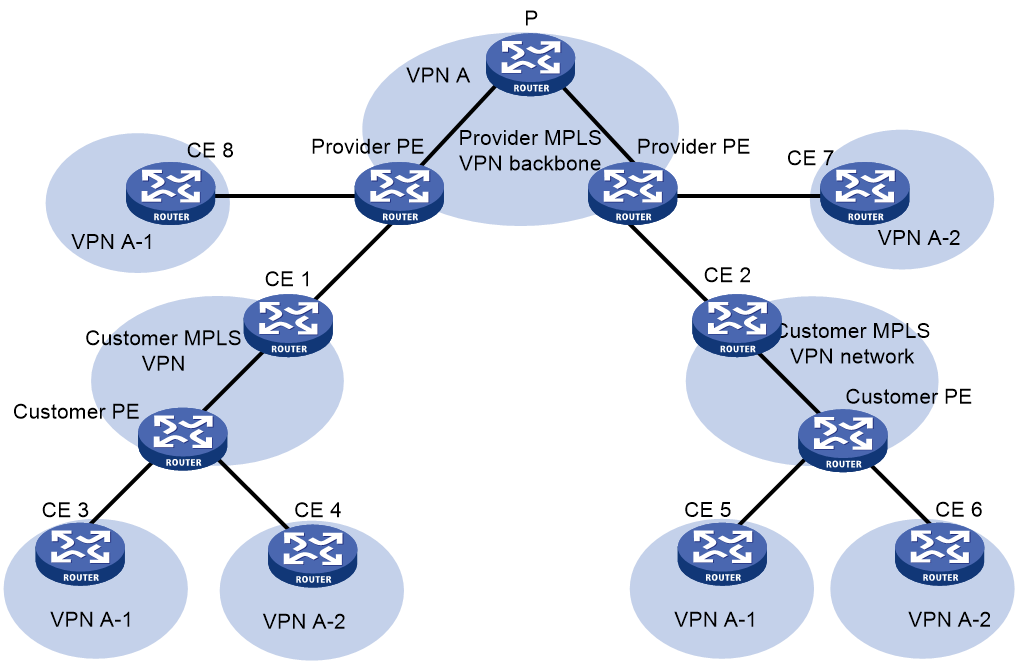
The nested VPN technology exchanges VPNv4 routes between PEs and CEs of the ISP MPLS L3VPN and allows a customer to manage its own internal VPNs. Figure 13 shows a nested VPN network. On the service provider's MPLS VPN network, there is a customer VPN named VPN A. The customer VPN contains two sub-VPNs, VPN A-1 and VPN A-2.
The service provider PEs consider the customer's network as a common VPN user and do not join any sub-VPNs. The service provider CE devices (CE 1 and CE 2) exchange VPNv4 routes including sub-VPN routing information with the service provider PEs, which implements the propagation of the sub-VPN routing information throughout the customer network.
The nested VPN technology supports both symmetric networking and asymmetric networking. Sites of the same VPN can have the same number or different numbers of internal VPNs. Nested VPN also supports multiple-level nesting of internal VPNs.
Figure 13 Network diagram for nested VPN
In a nested VPN network, routing information is propagated by using the following process:
1. After receiving VPN routes from customer CEs, a customer PE advertises VPN-IPv4 routes to the provider CEs through MP-BGP.
2. The provider CEs advertise the VPN-IPv4 routes to a provider PE through MP-BGP.
3. After receiving a VPN-IPv4 route, the provider PE keeps the customer's internal VPN information, and appends the customer's MPLS VPN attributes on the service provider network. It replaces the RD of the VPN-IPv4 route with the RD of the customer's MPLS VPN on the service provider network. It also adds the export route-target (ERT) attribute of the customer's MPLS VPN on the service provider network to the extended community attribute list of the route. The internal VPN information for the customer is maintained on the provider PE.
4. The provider PE advertises VPN-IPv4 routes carrying the comprehensive VPN information to the other PEs of the service provider.
5. After another provider PE receives the VPN-IPv4 routes, it matches the VPN-IPv4 routes to the import targets of its local VPNs. Each local VPN accepts routes of its own and advertises them to provider CEs. If a provider CE (such as CE 7 and CE 8 in Figure 13) is connected to a provider PE through an IPv4 connection, the PE advertises IPv4 routes to the CE. If it is a VPN-IPv4 connection (a customer MPLS VPN network), the PE advertises VPN-IPv4 routes to the CE.
6. After receiving VPN-IPv4 routes from the provider CE, a customer PE matches those routes to local import targets. Each customer VPN accepts only its own routes and advertises them to connected customer CEs (such as CE 3, CE 4, CE 5, and CE 6 in Figure 13).
HoVPN
Hierarchy of VPN (HoVPN), also called Hierarchy of PE (HoPE), prevents PEs from being bottlenecks and is applicable to large-scale VPN deployment.
HoVPN divides PEs into underlayer PEs (UPEs) or user-end PEs, and superstratum PEs (SPEs) or service provider-end PEs. UPEs and SPEs have different functions and comprise a hierarchical PE. The HoPE and common PEs can coexist in an MPLS network.
Figure 14 Basic architecture of HoVPN
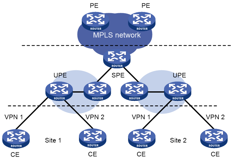
As shown in Figure 14, UPEs and SPEs play the following different roles:
· A UPE is directly connected to CEs. It provides user access. It maintains the routes of directly connected VPN sites. It does not maintain the routes of the remote sites in the VPN, or it only maintains their summary routes. A UPE assigns inner labels to the routes of its directly connected sites, and advertises the labels along with VPN routes to the SPE through MP-BGP. A UPE features high access capability, small routing table capacity, and low forwarding performance.
· An SPE is connected to UPEs and resides inside the service provider network. It manages and advertises VPN routes. It maintains all the routes of the VPNs connected through UPEs, including the routes of both the local and remote sites. An SPE advertises routes along with labels to UPEs, including the default routes of VPN instances or summary routes and the routes permitted by the routing policy. By using routing policies, you can control which sites in a VPN can communicate with each other. An SPE features large routing table capacity, high forwarding performance, and fewer interface resources.
Either MP-IBGP or MP-EBGP can run between SPE and UPE. When MP-IBGP runs between SPE and UPEs, the SPE acts as the RR of multiple UPEs and reflects routes between UPEs.
HoVPN supports HoPE recursion:
· An HoPE can act as a UPE to form a new HoPE with an SPE.
· An HoPE can act as an SPE to form a new HoPE with multiple UPEs.
HoVPN supports multilevel recursion. In HoPE recursion, the concepts of SPE and UPE are relative. A PE might be the SPE of its underlayer PEs and a UPE of its SPE at the same time.
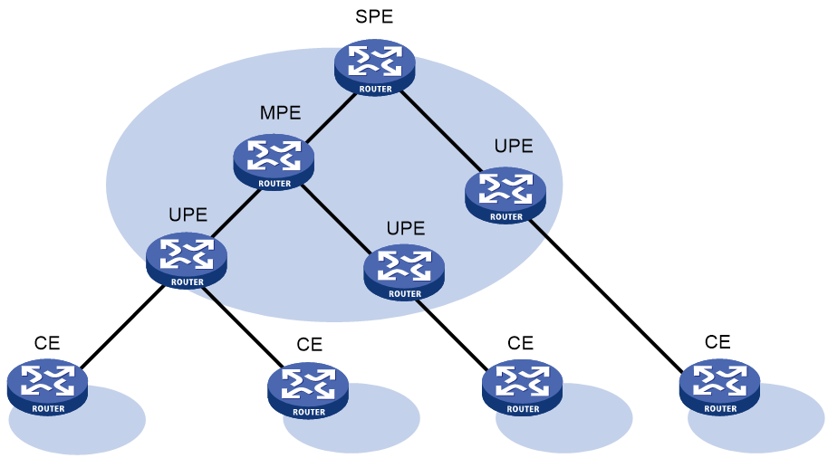
Figure 15 shows a three-level HoPE. The PE in the middle is called the middle-level PE (MPE). MP-BGP runs between SPE and MPE, and between MPE and UPE.
MP-BGP advertises the following routes:
· All the VPN routes of UPEs to the SPEs.
· The default routes of the VPN instance of the SPEs or the VPN routes permitted by the routing policies to the UPEs.
The SPE maintains the VPN routes of all sites in the HoVPN. Each UPE maintains only VPN routes of its directly connected sites. An MPE has fewer routes than the SPE but has more routes than a UPE.
OSPF VPN extension
This section describes the OSPF VPN extension. For more information about OSPF, see Layer 3—IP Routing Configuration Guide.
OSPF for VPNs on a PE
If OSPF runs between a CE and a PE to exchange VPN routes, the PE must support multiple OSPF instances to create independent routing tables for VPN instances. Each OSPF process is bound to a VPN instance. Routes learned by an OSPF process are added into the routing table of the bound VPN instance.
OSPF area configuration between a PE and a CE
The OSPF area between a PE and a CE can be either a non-backbone area or a backbone area.
In the OSPF VPN extension application, the MPLS VPN backbone is considered the backbone area (area 0). The area 0 of each site must be connected to the MPLS VPN backbone (physically connected or logically connected through a virtual link) because OSPF requires that the backbone area be contiguous.
BGP/OSPF interaction
If OSPF runs between PEs and CEs, each PE redistributes BGP routes to OSPF and advertises the routes to CEs through OSPF. OSPF considers the routes redistributed from BGP as external routes but the OSPF routes actually belong to the same OSPF domain. This problem can be resolved by configuring the same domain ID for sites in an OSPF domain.
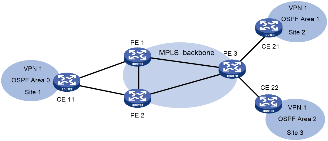
Figure 16 Network diagram for BGP/OSPF interaction
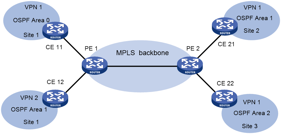
As shown in Figure 16, CE 11, CE 21, and CE 22 belong to the same VPN and the same OSPF domain.
Before domain ID configuration, VPN 1 routes are advertised from CE 11 to CE 21 and CE 22 by using the following process:
1. PE 1 redistributes OSPF routes from CE 11 into BGP, and advertises the VPN routes to PE 2 through BGP.
2. PE 2 redistributes the BGP routes to OSPF, and advertises them to CE 21 and CE 22 in AS External LSAs (Type 5) or NSSA External LSAs (Type 7).
After domain ID configuration, VPN 1 routes are advertised from CE 11 to CE 21 and CE 22 by using the following process:
3. PE 1 redistributes OSPF routes into BGP, adds the domain ID to the redistributed BGP VPNv4 routes as a BGP extended community attribute, and advertises the routes to PE 2.
4. PE 2 compares the domain ID in the received routes with the locally configured domain ID. If they are the same and the received routes are intra-area or inter-area routes, OSPF advertises these routes in Network Summary LSAs (Type 3). Otherwise, OSPF advertises these routes in AS External LSAs (Type 5) or NSSA External LSAs (Type 7).
Routing loop avoidance
Figure 17 Network diagram for routing loop avoidance
As shown in Figure 17, Site 1 is connected to two PEs. When a PE advertises VPN routes learned from MP-BGP to Site 1 through OSPF, the routes might be received by the other PE. This results in a routing loop.
OSPF VPN extension uses the following tags to avoid routing loops:
· DN bit (for Type 3 LSAs)—When a PE redistributes BGP routes into OSPF and creates Type 3 LSAs, it sets the DN bit for the LSAs. When receiving the Type 3 LSAs advertised by CE 11, the other PE ignores the LSAs whose DN bit is set to avoid routing loops.
· Route tag (for Type 5 or 7 LSAs)—The two PEs use the same route tag. When a PE redistributes BGP routes into OSPF and creates Type 5 or 7 LSAs, it adds the route tag to the LSAs. When receiving the Type 5 or 7 LSAs advertised by CE 11, the other PE compares the route tag in the LSAs against the local route tag. If they are the same, the PE ignores the LSAs to avoid routing loops.
OSPF sham link
As shown in Figure 18, two routes exist between Site 1 and Site 2 of VPN 1:
· A route over MPLS backbone—It is an inter-area route if PE 1 and PE 2 have the same domain ID, or is an external route if PE 1 and PE 2 are configured with no domain ID or with different domain IDs.
· A direct route between CEs—It is an intra-area route that is called a backdoor link.
VPN traffic is always forwarded through the backdoor link because it has a higher priority than the inter-area route. To forward VPN traffic over the inter-area route, you can establish a sham link between the two PEs to change the inter-area route to an intra-area route.
Figure 18 Network diagram for sham link
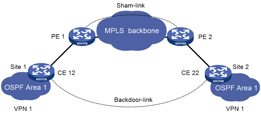
A sham link is considered a virtual point-to-point link within a VPN and is advertised in a Type 1 LSA. It is identified by the source IP address and destination IP address that are the local PE address and the remote PE address in the VPN address space. Typically, the source and destination addresses are loopback interface addresses with a 32-bit mask.
To add a route to the destination IP address of a sham link to a VPN instance, the remote PE must advertise the source IP address of the sham link as a VPN-IPv4 address through MP-BGP. To avoid routing loops, a PE does not advertise the sham link's destination address.
BGP AS number substitution and SoO attribute
BGP detects routing loops by examining AS numbers. If EBGP runs between PE and CE, you must assign different AS numbers to geographically different sites or configure the BGP AS number substitution feature to ensure correct transmission of routing information.
The BGP AS number substitution feature allows geographically different CEs to use the same AS number. If the AS_PATH of a route contains the AS number of a CE, the PE replaces the AS number with its own AS number before advertising the route to that CE.
After you enable the BGP AS number substitution feature, the PE performs BGP AS number substitution for all routes and re-advertises them to connected CEs in the peer group.
Figure 19 Application of BGP AS number substitution and SoO attribute
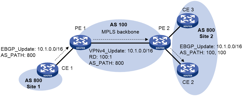
As shown in Figure 19, both Site 1 and Site 2 use the AS number 800. AS number substitution is enabled on PE 2 for CE 2. Before advertising updates received from CE 1 to CE 2, PE 2 substitutes its own AS number 100 for the AS number 800. In this way, CE 2 can correctly receive the routing information from CE 1.
However, the AS number substitution feature also introduces a routing loop in Site 2 because route updates originated from CE 3 can be advertised back to Site 2 through PE 2 and CE 2. To remove the routing loop, you can configure the same SoO attribute on PE 2 for CE 2 and CE 3. PE 2 adds the SoO attribute to route updates received from CE 2 or CE 3, and checks the SoO attribute of route updates to be advertised to CE 2 or CE 3. The SoO attribute of the route updates from CE 3 is the same as the SoO attribute for CE 2, and PE 2 does not advertise route updates to CE 2.
For more information about the SoO attribute, see basic BGP configuration in Layer 3—IP Routing Configuration Guide.
MPLS L3VPN FRR
MPLS L3VPN Fast Reroute (FRR) is applicable to a dual-homed scenario, as shown in Figure 20. By using BFD to detect the primary link, FRR enables a PE to use the backup link when the primary link fails. The PE then selects a new optimal route, and uses the new optimal route to forward traffic.
MPLS L3VPN FRR supports the following types of backup:
· VPNv4 route backup for a VPNv4 route.
· VPNv4 route backup for an IPv4 route.
· IPv4 route backup for a VPNv4 route.
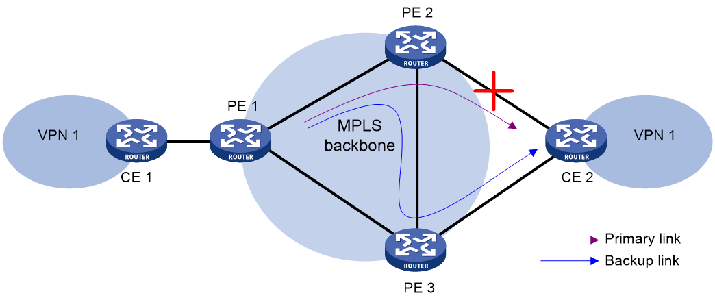
VPNv4 route backup for a VPNv4 route
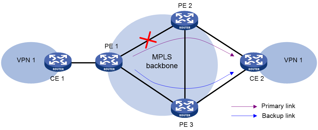
As shown in Figure 20, configure FRR on the ingress node PE 1, and specify the backup next hop for VPN 1 as PE 3. When PE 1 receives a VPNv4 route to CE 2 from both PE 2 and PE 3, it uses the route from PE 2 as the primary link, and the route from PE 3 as the backup link.
Configure BFD for LSPs or MPLS TE tunnels on PE 1 to detect the connectivity of the public tunnel from PE 1 to PE 2. When the tunnel PE 1—PE 2 operates correctly, traffic from CE 1 to CE 2 goes through the path CE 1—PE 1—PE 2—CE 2. When the tunnel fails, the traffic goes through the path CE 1—PE 1—PE 3—CE 2.
In this scenario, PE 1 is responsible for primary link detection and traffic switchover.
For more information about BFD for LSPs or MPLS TE tunnels, see "Configuring MPLS OAM."
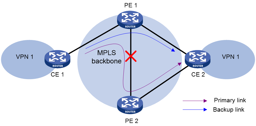
VPNv4 route backup for an IPv4 route
As shown in Figure 21, configure FRR on the egress node PE 2, and specify the backup next hop for VPN 1 as PE 3. When PE 2 receives an IPv4 route from CE 2 and a VPNv4 route from PE 3 (both routes are destined for VPN 1 connected to CE 2), PE 2 uses the IPv4 route as the primary link, and the VPNv4 route as the backup link.
PE 2 uses ARP or echo-mode BFD to detect the connectivity of the link from PE 2 to CE 2. When the link operates correctly, traffic from CE 1 to CE 2 goes through the path CE 1—PE 1—PE 2—CE 2. When the link fails, PE 2 switches traffic to the link PE 2—PE 3—CE 2, and traffic from CE 1 to CE 2 goes through the path CE 1—PE 1—PE 2—PE 3—CE 2. This avoids traffic interruption before route convergence completes (switching to the link CE 1—PE 1—PE 3—CE 2).
In this scenario, PE 2 is responsible for primary link detection and traffic switchover.
IPv4 route backup for a VPNv4 route
As shown in Figure 22, configure FRR on PE 1, and specify the backup next hop for VPN 1 as CE 2. When PE 1 receives an IPv4 route from CE 2 and a VPNv4 route from PE 2 (both routes are destined for VPN 1 connected to CE 2), PE 1 uses the VPNv4 route as the primary link, and the IPv4 route as the backup link.
Configure BFD for LSPs or MPLS TE tunnels on PE 1 to detect the connectivity of the public tunnel from PE 1 to PE 2. When the tunnel operates correctly, traffic from CE 1 to CE 2 goes through the path CE 1—PE 1—PE 2—CE 2. When the tunnel fails, the traffic goes through the path CE 1—PE 1—CE 2.
In this scenario, PE 1 is responsible for primary link detection and traffic switchover.
ECMP VPN route redistribution
This feature enables a VPN instance to redistribute all routes that have the same prefix and RD into its routing table. Based on the ECMP routes, the device can perform load sharing (as configured by the balance command) or MPLS L3VPN FRR. For more information about the balance command, see basic BGP configuration in Layer 3—IP Routing Command Reference.
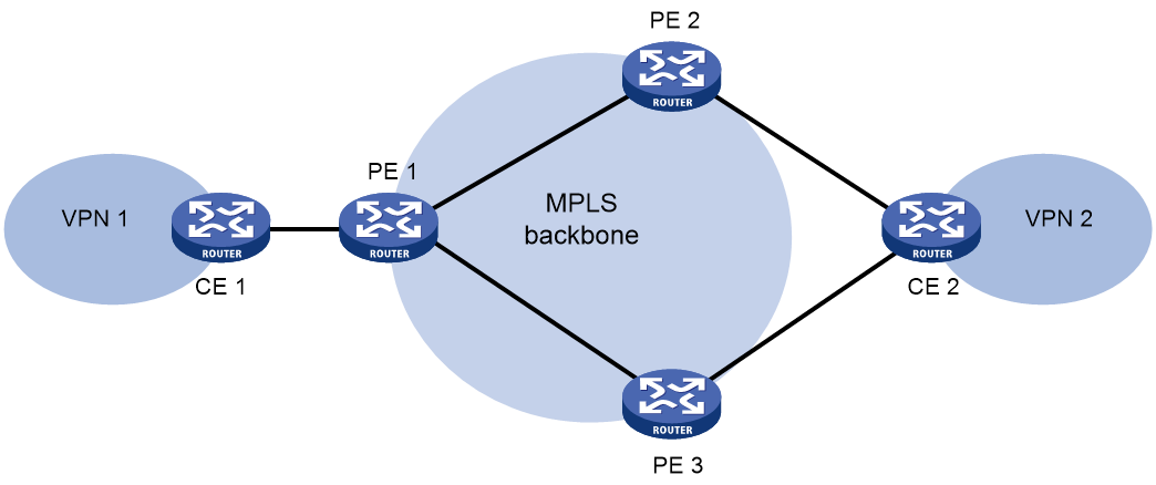
As shown in Figure 23, CE 1 accesses the backbone network through VPN instance VPN1 created on PE 1. The RD of VPN instance VPN1 is 1:1. CE 2 accesses the backbone network through VPN instances created on PE 2 and PE 3. The VPN instances created on PE 2 and PE 3 have the same name VPN2 and the same RD 1:2. VPN instances VPN1 and VPN2 can communicate with each other.
Both PE 2 and PE 3 can advertise routes from CE 2 to PE 1, and the advertised routes have the same RD 1:2. By default, BGP redistributes only the optimal route into the routing table of VPN instance VPN1. After you enable this feature on VPN instance VPN1, BGP redistributes routes from both PE 2 and PE 3 to the routing table of VPN instance VPN1.
Protocols and standards
· RFC 3107, Carrying Label Information in BGP-4
· RFC 4360, BGP Extended Communities Attribute
· RFC 4364, BGP/MPLS IP Virtual Private Networks (VPNs)
· RFC 4577, OSPF as the Provider/Customer Edge Protocol for BGP/MPLS IP Virtual Private Networks (VPNs)
MPLS L3VPN tasks at a glance
Unless otherwise indicated, configure MPLS L3VPN on PEs.
To configure MPLS L3VPN, perform the following tasks:
1. Configuring MPLS L3VPN basics
b. Configuring routing between a PE and a CE
c. Configuring routing between PEs
d. (Optional.) Configuring BGP VPNv4 route control
2. Configuring advanced MPLS L3VPN networks
Choose the following tasks as needed:
Perform this task when sites of a VPN are connected to different ASs of an ISP.
Deploy the nest VPN when a large number of VPNs exist and you want to hide from the outside of the customer internal VPNs.
HoVPN prevents PEs from being bottlenecks and is applicable to large-scale VPN deployment.
3. (Optional.) Specifying the VPN label processing mode on the egress PE
4. (Optional.) Configuring MPLS L3VPN FRR
5. (Optional.) Configuring a TTL processing mode for tunnels associated with a VPN instance
6. (Optional.) Controlling route advertisement and reception in an MPLS L3VPN network
¡ Configuring an OSPF sham link
¡ Configuring BGP AS number substitution and SoO attribute
¡ Configuring BGP RT filtering
Perform this task to reduce the number of routes advertised in an MPLS L3VPN.
¡ Configuring the BGP additional path feature
Perform this task to enable BGP to advertise multiple routes with the same prefix and different next hops to a peer or peer group.
¡ Configuring link bandwidth attributes for BGP VPNv4 routes
¡ Enabling independent routing tables for BGP VPNv4 routes and BGP-VPN instance routes
¡ Minimizing the priority of BGP routes advertised to peers
¡ Specifying a local network to be advertised in the public instance or a VPN instance
¡ Configuring route replication
Perform this task to enable a VPN instance to communicate with the public network or other VPN instances by replicating routes from the public network or other VPN instances.
¡ Enabling ECMP VPN route redistribution
Perform this task to enable a VPN instance to redistribute all routes that have the same prefix and RD into its routing table to perform load sharing or MPLS L3VPN FRR.
¡ Enabling prioritized withdrawal of specific routes
Configure BGP to send withdrawal messages of specific routes prior to other routes to ensure fast route switchover and reduce the traffic interruption time for the specific routes.
¡ Configuring BGP next hop recursion based on a routing policy
7. (Optional.) Configuring a VPN peer
8. (Optional.) Maintaining MPLS L3VPN networks
¡ Enabling SNMP notifications for MPLS L3VPN
¡ Enabling logging for BGP route flapping
Prerequisites for MPLS L3VPN
Before you configure basic MPLS L3VPN, perform the following tasks:
1. Configure an IGP on the PEs and P devices to ensure IP connectivity within the MPLS backbone.
2. Configure basic MPLS for the MPLS backbone.
3. Configure MPLS LDP on the PEs and P devices to establish LDP LSPs.
Configuring VPN instances
All VPN instance configurations are performed on PEs.
Creating a VPN instance
About this task
A VPN instance is a collection of the VPN membership and routing rules of its associated site. A VPN instance might correspond to more than one VPN.
Procedure
1. Enter system view.
system-view
2. Specify a label range for all VPN instances.
mpls per-vrf-label range minimum maximum
By default, no label range is configured.
3. Create a VPN instance and enter VPN instance view.
ip vpn-instance vpn-instance-name
4. Configure an RD for the VPN instance.
route-distinguisher route-distinguisher
By default, no RD is configured for a VPN instance.
5. (Optional.) Configure a description for the VPN instance.
description text
By default, no description is configured for a VPN instance.
6. (Optional.) Configure a VPN ID for the VPN instance.
vpn-id vpn-id
By default, no VPN ID is configured for a VPN instance.
7. (Optional.) Configure an SNMP context for the VPN instance.
snmp context-name context-name
By default, no SNMP context is configured.
8. Specify a label allocation mode.
apply-label { per-instance [ static static-label-value ] | per-route }
By default, BGP allocates labels on a per-next-hop basis.
|
|
CAUTION: Executing this command will re-advertise all routes in the VPN instance, which will cause temporary interruption of running services in the VPN instance. Please be cautious. |
Associating a VPN instance with a Layer 3 interface
1. Enter system view.
system-view
2. Enter interface view.
interface interface-type interface-number
3. Associate a VPN instance with the interface.
ip binding vpn-instance vpn-instance-name
By default, an interface is not associated with a VPN instance and belongs to the public network.
|
|
CAUTION: Associating a VPN instance with an interface or disassociating a VPN instance from an interface will clear the IP address and routing protocol settings of the interface. |
The ip binding vpn-instance command deletes the IP address of the current interface. You must reconfigure an IP address for the interface after executing the command.
Configuring route related attributes for a VPN instance
Restrictions and guidelines
Configurations made in VPN instance view apply to both IPv4 VPN and IPv6 VPN.
IPv4 VPN prefers the configurations in VPN instance IPv4 address family view over the configurations in VPN instance view.
Prerequisites
Before you perform this task, create the routing policies to be used by this task. For information about routing policies, see Layer 3—IP Routing Configuration Guide.
Procedure
1. Enter system view.
system-view
2. Enter VPN instance view or VPN instance IPv4 address family view.
¡ Enter VPN instance view.
ip vpn-instance vpn-instance-name
¡ Execute the following commands in sequence to enter VPN instance IPv4 address family view:
ip vpn-instance vpn-instance-name
address-family ipv4
3. Configure route targets.
vpn-target vpn-target&<1-8> [ both | export-extcommunity | import-extcommunity ]
By default, no route targets are configured.
4. Set the maximum number of active routes.
routing-table limit number { warn-threshold | simply-alert }
By default, the number of active routes in a VPN instance is not limited.
Setting the maximum number of active routes for a VPN instance can prevent the device from learning too many routes.
5. Apply an import routing policy.
import route-policy route-policy
By default, all routes matching the import target attribute are accepted.
6. Apply an export routing policy.
export route-policy route-policy
By default, routes to be advertised are not filtered.
7. Apply a tunnel policy to the VPN instance.
tnl-policy tunnel-policy-name
By default, only one tunnel is selected (no load balancing) in this order: LSP tunnel, CRLSP tunnel, SRLSP tunnel, SR-TE policy tunnel.
If the specified tunnel policy does not exist, the default tunnel policy is used.
For information about tunnel policies, see "Configuring tunnel policies."
Configuring routing between a PE and a CE
Configuring static routing between a PE and a CE
About this task
Perform this configuration on the PE. On the CE, configure a common static route.
For more information about static routing, see Layer 3—IP Routing Configuration Guide.
Procedure
1. Enter system view.
system-view
2. Configure a static route for a VPN instance.
ip route-static vpn-instance s-vpn-instance-name dest-address { mask-length | mask } { interface-type interface-number [ next-hop-address ] | next-hop-address [ public ] [ track track-entry-number ] | vpn-instance d-vpn-instance-name next-hop-address [ track track-entry-number ] } [ permanent ] [ preference preference ] [ tag tag-value ] [ description text ]
Configuring RIP between a PE and a CE
About this task
Perform this configuration on the PE. On the CE, create a common RIP process.
For more information about RIP, see Layer 3—IP Routing Configuration Guide.
Procedure
1. Enter system view.
system-view
2. Create a RIP process for a VPN instance and enter RIP view.
rip [ process-id ] vpn-instance vpn-instance-name
A RIP process can belong to only one VPN instance.
3. Redistribute BGP routes.
import-route bgp [ as-number ] [ allow-ibgp ] [ cost cost-value | route-policy route-policy-name | tag tag ] *
By default, RIP does not redistribute routes from other routing protocols.
4. Enable RIP on the interface attached to the specified network.
network network-address [ wildcard-mask ]
By default, RIP is disabled on an interface.
Configuring OSPF between a PE and a CE
About this task
Perform this configuration on the PE. On the CE, create a common OSPF process.
For more information about OSPF, see Layer 3—IP Routing Configuration Guide.
Procedure
1. Enter system view.
system-view
2. Create an OSPF process for a VPN instance and enter the OSPF view.
ospf [ process-id | router-id router-id ] * vpn-instance vpn-instance-name
|
Parameter |
Usage guidelines |
|
router-id router-id |
An OSPF process bound to a VPN instance does not use the public network router ID configured in system view. Therefore, you must specify a router ID when creating a process or configure an IP address for a minimum of one interface in the bound VPN instance. |
|
vpn-instance vpn-instance-name |
An OSPF process can belong to only one VPN instance. If you delete a VPN instance, all OSPF processes of the VPN instance are also deleted. |
3. Redistribute BGP routes.
import-route bgp [ as-number ] [ allow-ibgp ] [ cost cost-value | nssa-only | route-policy route-policy-name | tag tag | type type ] *
By default, OSPF does not redistribute routes from other routing protocols.
If the vpn-instance-capability simple command is not configured for the OSPF process, the allow-ibgp keyword is optional to redistribute VPNv4 routes learned from MP-IBGP peers. In any other cases, if you do not specify the allow-ibgp keyword, the OSPF process does not redistribute VPNv4 routes learned from MP-IBGP peers.
4. (Optional.) Set an OSPF domain ID.
domain-id domain-id [ secondary ]
The default domain ID is 0.
|
Description |
Restrictions and guidelines |
|
The domain ID is carried in the routes of the OSPF process. When redistributing routes from the OSPF process, BGP adds the domain ID as an extended community attribute into BGP route. |
An OSPF process can be configured with only one primary domain ID. Domain IDs of different OSPF processes can be the same. All OSPF processes of a VPN must be configured with the same domain ID. |
5. (Optional.) Configure the type codes of OSPF extended community attributes.
ext-community-type { domain-id type-code1 | router-id type-code2 | route-type type-code3 }
The defaults are as follows:
¡ 0x0005 for Domain ID.
¡ 0x0107 for Router ID.
¡ 0x0306 for Route Type.
6. Create an OSPF area and enter area view.
area area-id
7. Enable OSPF on the interface attached to the specified network in the area.
network ip-address wildcard-mask
By default, an interface neither belongs to any area nor runs OSPF.
Configuring IS-IS between a PE and a CE
About this task
Perform this configuration on the PE. On the CE, configure common IS-IS.
For more information about IS-IS, see Layer 3—IP Routing Configuration Guide.
Procedure
1. Enter system view.
system-view
2. Create an IS-IS process for a VPN instance and enter IS-IS view.
isis [ process-id ] vpn-instance vpn-instance-name
An IS-IS process can belong to only one VPN instance.
3. Configure a network entity title for the IS-IS process.
network-entity net
By default, no NET is configured.
4. Enter IS-IS IPv4 unicast address family view.
address-family ipv4
5. Redistribute BGP routes.
import-route bgp [ as-number ] [ allow-ibgp ] [ cost cost-value | cost-type { external | internal } | [ level-1 | level-1-2 | level-2 ] | route-policy route-policy-name | tag tag ] *
By default, IS-IS does not redistribute routes from other routing protocols.
6. Return to system view.
quit
quit
7. Enter interface view.
interface interface-type interface-number
8. Enable the IS-IS process on the interface.
isis enable [ process-id ]
By default, no IS-IS process is enabled on the interface.
Configuring EBGP between a PE and a CE
Configuring the PE
1. Enter system view.
system-view
2. Enable a BGP instance and enter BGP instance view.
bgp as-number [ instance instance-name ]
By default, BGP is not enabled.
3. Enter BGP-VPN instance view.
ip vpn-instance vpn-instance-name
Configuration commands in BGP-VPN instance view are the same as those in BGP instance view. For more information, see basic BGP configuration in Layer 3—IP Routing Configuration Guide.
4. Configure the CE as the VPN EBGP peer.
peer { group-name | ip-address [ mask-length ] } as-number as-number
5. Create the BGP-VPN IPv4 unicast address family and enter its view.
address-family ipv4 [ unicast ]
6. Enable IPv4 unicast route exchange with the specified peer.
peer { group-name | ip-address [ mask-length ] } enable
By default, BGP does not exchange IPv4 unicast routes with a peer.
7. Redistribute the routes of the local CE.
import-route protocol [ { process-id | all-processes } [ allow-direct | med med-value | route-policy route-policy-name ] * ]
A PE must redistribute the routes of the local CE into its VPN routing table so it can advertise them to the peer PE.
8. Allow the local AS number to appear in the AS_PATH attribute of a received route, and set the maximum number of repetitions.
peer { group-name | ip-address [ mask-length ] } allow-as-loop [ number ]
By default, BGP discards incoming route updates that contain the local AS number.
Execute this command in a hub-spoke network where EBGP is running between a PE and a CE to enable the PE to receive the route updates from the CE.
Configuring the CE
1. Enter system view.
system-view
2. Enable a BGP instance and enter BGP instance view.
bgp as-number [ instance instance-name ]
By default, BGP is not enabled.
3. Configure the PE as a BGP peer.
peer { group-name | ip-address [ mask-length ] } as-number as-number
4. Create the BGP IPv4 unicast address family and enter its view.
address-family ipv4 [ unicast ]
5. Enable IPv4 unicast route exchange with the specified peer or peer group.
peer { group-name | ip-address [ mask-length ] } enable
By default, BGP does not exchange IPv4 unicast routes with any peer.
6. Configure route redistribution.
import-route protocol [ { process-id | all-processes } [ allow-direct | med med-value | route-policy route-policy-name ] * ]
A CE must redistribute its routes to the PE so the PE can advertise them to the peer CE.
Configuring IBGP between a PE and a CE
Restrictions and guidelines
Use IBGP between PE and CE only in a basic MPLS L3VPN network. In networks such as Hub&Spoke, Extranet, inter-AS VPN, carrier's carrier, nested VPN, and HoVPN, you cannot use IBGP between PE and CE.
Configuring the PE
1. Enter system view.
system-view
2. Enable a BGP instance and enter BGP instance view.
bgp as-number [ instance instance-name ]
By default, BGP is not enabled.
3. Enter BGP-VPN instance view.
ip vpn-instance vpn-instance-name
Configuration commands in BGP-VPN instance view are the same as those in BGP instance view. For more information, see basic BGP configuration in Layer 3—IP Routing Configuration Guide.
4. Configure the CE as the VPN IBGP peer.
peer { group-name | ip-address [ mask-length ] } as-number as-number
5. Create the BGP-VPN IPv4 unicast address family and enter its view.
address-family ipv4 [ unicast ]
6. Enable IPv4 unicast route exchange with the specified peer.
peer { group-name | ip-address [ mask-length ] } enable
By default, BGP does not exchange IPv4 unicast routes with any peer.
7. Configure the CE as a client of the RR to enable the PE to advertise routes learned from the IBGP peer CE to other IBGP peers.
peer { group-name | ip-address [ mask-length ] } reflect-client
By default, no RR or RR client is configured.
Configuring an RR does not change the next hop of a route. To change the next hop of a route, configure an inbound policy on the receiving side.
8. (Optional.) Enable route reflection between clients.
reflect between-clients
By default, route reflection between clients is enabled.
9. (Optional.) Configure the cluster ID for the RR.
reflector cluster-id { cluster-id | ip-address }
By default, the RR uses its own router ID as the cluster ID.
If multiple RRs exist in a cluster, use this command to configure the same cluster ID for all RRs in the cluster to avoid routing loops.
Configuring the CE
1. Enter system view.
system-view
2. Enable a BGP instance and enter BGP instance view.
bgp as-number [ instance instance-name ]
By default, BGP is not enabled.
3. Configure the PE as an IBGP peer.
peer { group-name | ip-address [ mask-length ] } as-number as-number
4. Create the BGP IPv4 unicast address family and enter its view.
address-family ipv4 [ unicast ]
5. Enable IPv4 unicast route exchange with the specified peer.
peer { group-name | ip-address [ mask-length ] } enable
By default, BGP does not exchange IPv4 unicast routes with a peer.
6. Configure route redistribution.
import-route protocol [ { process-id | all-processes } [ allow-direct | med med-value | route-policy route-policy-name ] * ]
A CE must redistribute its routes to the PE so the PE can advertise them to the peer CE.
Configuring routing between PEs
1. Enter system view.
system-view
2. Enable a BGP instance and enter BGP instance view.
bgp as-number [ instance instance-name ]
By default, BGP is not enabled.
3. Configure the remote PE as a BGP peer.
peer { group-name | ip-address [ mask-length ] } as-number as-number
4. (Optional.) Specify the source interface for TCP connections.
peer { group-name | ip-address [ mask-length ] } connect-interface interface-type interface-number
By default, BGP uses the output interface of the optimal route destined for the peer as the source interface.
5. Create the BGP VPNv4 address family and enter its view.
address-family vpnv4
6. Enable BGP VPNv4 route exchange with the specified peer.
peer { group-name | ip-address [ mask-length ] } enable
By default, BGP does not exchange BGP VPNv4 routes with a peer.
Configuring BGP VPNv4 route control
About BGP VPNv4 route control
BGP VPNv4 route control is configured similarly with BGP route control, except that it is configured in BGP VPNv4 address family view. For more information about BGP route control, see basic BGP configuration and advanced BGP configuration in Layer 3—IP Routing Configuration Guide.
Controlling BGP VPNv4 route advertisement, reception, and saving
1. Enter system view.
system-view
2. Enter BGP instance view.
bgp as-number [ instance instance-name ]
3. Enter BGP VPNv4 address family view.
address-family vpnv4
4. Advertise a default VPN route to a peer or peer group.
peer { group-name | ipv4-address [ mask-length ] } default-route-advertise vpn-instance vpn-instance-name
By default, no default VPN route is advertised to a peer or peer group.
5. Set the maximum number of routes BGP can receive from a peer or peer group.
peer { group-name | ipv4-address [ mask-length ] } route-limit prefix-number [ { alert-only | discard | reconnect reconnect-time } | percentage-value ] *
By default, the number of routes that BGP can receive from a peer or peer group is not limited.
6. Save all route updates from a peer or peer group.
peer { group-name | ipv4-address [ mask-length ] } keep-all-routes
By default, BGP does not save route updates from a peer.
Setting a preferred value for received routes
1. Enter system view.
system-view
2. Enter BGP instance view.
bgp as-number [ instance instance-name ]
3. Enter BGP VPNv4 address family view.
address-family vpnv4
4. Set a preferred value for routes received from a peer or peer group.
peer { group-name | ipv4-address [ mask-length ] } preferred-value value
By default, the preferred value for routes received from a peer or peer group is 0.
Configuring BGP VPNv4 route reflection
About this task
To ensure the connectivity of IBGP peers, you must establish full-mesh IBGP connections, which costs massive network and CPU resources.
To reduce IBGP connections in the network, you can configure a router as a route reflector (RR) and configure other routers as its clients. You only need to establish IBGP connections between the RR and its clients to enable the RR to forward routes to the clients.
Procedure
1. Enter system view.
system-view
2. Enter BGP instance view.
bgp as-number [ instance instance-name ]
3. Enter BGP VPNv4 address family view.
address-family vpnv4
4. Configure the device as a route reflector and specify a peer or peer group as its client.
peer { group-name | ipv4-address [ mask-length ] } reflect-client
By default, no route reflector or client is configured.
5. (Optional.) Enable route reflection between clients.
reflect between-clients
By default, route reflection between clients is enabled.
6. (Optional.) Configure a cluster ID for the RR.
reflector cluster-id { cluster-id | ip-address }
By default, the RR uses its own router ID as the cluster ID.
7. (Optional.) Configure a filtering policy for reflected routes.
rr-filter { ext-comm-list-number | ext-comm-list-name }
By default, the RR does not filter reflected routes.
8. (Optional.) Allow the RR to change the attributes of routes to be reflected.
reflect change-path-attribute
By default, RR cannot change the attributes of routes to be reflected.
9. (Optional.) Specify a peer or peer group as a client of the nearby cluster.
peer { group-name | ipv4-address [ mask-length ] } reflect-nearby-group
By default, the nearby cluster does not have any clients.
The RR does not change the next hop of routes reflected to clients in the nearby cluster.
Configuring BGP VPNv4 route attributes
1. Enter system view.
system-view
2. Enter BGP instance view.
bgp as-number [ instance instance-name ]
3. Enter BGP VPNv4 address family view.
address-family vpnv4
4. Configure the NEXT_HOP attribute.
¡ Set the device as the next hop for routes sent to a peer or peer group.
peer { group-name | ipv4-address [ mask-length ] } next-hop-local
By default, the device uses its address as the next hop for routes advertised to peers.
¡ Configure the device to not change the next hop of routes advertised to a peer or peer group.
peer { group-name | ipv4-address [ mask-length ] } next-hop-invariable
By default, the device uses its address as the next hop for routes advertised to peers.
On an RR in an inter-AS option C scenario, you must execute this command to not change the next hop of VPNv4 routes advertised to BGP peers and RR clients.
5. Configure the AS_PATH attribute.
¡ Allow the local AS number to appear in the AS_PATH attribute of a received route and set the maximum number of repetitions.
peer { group-name | ipv4-address [ mask-length ] } allow-as-loop [ number ]
By default, BGP discards incoming routes that contain the local AS number.
¡ Remove private AS numbers in BGP updates sent to an EBGP peer or peer group.
peer { group-name | ipv4-address [ mask-length ] } public-as-only [ { force | limited } [ replace ] [ include-peer-as ] ]
By default, BGP updates sent to an EBGP peer or peer group can carry both public and private AS numbers.
6. Advertise the COMMUNITY attribute to a peer or peer group.
peer { group-name | ipv4-address [ mask-length ] } advertise-community
By default, BGP does not advertise the COMMUNITY attribute to a peer or peer group.
7. Configure the SoO attribute for a peer for peer group.
peer { group-name | ipv4-address [ mask-length ] } soo site-of-origin
By default, the SoO attribute is not configured.
Configuring BGP VPNv4 route filtering
1. Enter system view.
system-view
2. Enter BGP instance view.
bgp as-number [ instance instance-name ]
3. Enter BGP VPNv4 address family view.
address-family vpnv4
4. Filter advertised routes.
filter-policy { ipv4-acl-number | prefix-list prefix-list-name } export [ direct | { isis | ospf | rip } process-id | static ]
By default, BGP does not filter advertised routes.
5. Filter received routes.
filter-policy { ipv4-acl-number | prefix-list prefix-list-name } import
By default, BGP does not filter received routes.
6. Configure AS_PATH list-based route filtering for a peer or peer group.
peer { group-name | ipv4-address [ mask-length ] } as-path-acl as-path-acl-number { export | import }
By default, AS_PATH list-based route filtering is not configured.
7. Configure ACL-based route filtering for a peer or peer group.
peer { group-name | ipv4-address [ mask-length ] } filter-policy ipv4-acl-number { export | import }
By default, ACL-based route filtering is not configured.
8. Configure IP prefix list-based route filtering for a peer or peer group.
peer { group-name | ipv4-address [ mask-length ] } prefix-list prefix-list-name { export | import }
By default, no IP prefix list-based route filtering is configured.
9. Apply a routing policy to routes advertised to or received from a peer or peer group.
peer { group-name | ipv4-address [ mask-length ] } route-policy route-policy-name { export | import }
By default, no routing policy is applied for a peer.
10. Enable route target filtering for received BGP VPNv4 routes.
policy vpn-target
By default, route target filtering is enabled for received VPNv4 routes. Only VPNv4 routes whose export route target attribute matches the local import route target attribute are added to the routing table.
11. Enable the first AS number check for EBGP route advertisement to EBGP peers.
peer-as-check enable
By default, BGP does not check the first AS number of a received route and advertises the route to other peers.
After you execute this command, BGP checks the first AS number of a received route. If the AS number of an EBGP peer is the first AS number of the EBGP route to be advertised, BGP will not advertise the route to that EBGP peer.
Configuring BGP VPNv4 route dampening
About this task
This feature enables BGP to not select unstable routes as optimal routes.
Restrictions and guidelines
This feature applies only to IBGP routes.
If an IBGP peer goes down after you configure this feature, VPNv4 routes coming from the peer are dampened but not deleted.
Procedure
1. Enter system view.
system-view
2. Enter BGP instance view.
bgp as-number [ instance instance-name ]
3. Enter BGP VPNv4 address family view.
address-family vpnv4
4. Configure BGP VPNv4 route dampening.
dampening ibgp[ half-life-reachable half-life-unreachable reuse suppress ceiling | route-policy route-policy-name ] *
By default, BGP VPNv4 route dampening is not configured.
Configuring BGP VPNv4 routes to use private network next hops
About this task
By default, the device does not change the next hop attribute of a received BGP VPNv4 route. The next hop address of a BGP VPNv4 route is a public address. This feature changes the next hop of a BGP VPNv4 route received from a peer or peer group to an IP address in the VPN instance. The outgoing label of the VPNv4 route is also changed to an invalid value. For example, the device received a VPNv4 route and its next hop address is 10.1.1.1, which is a public address by default. After this feature is configured, the next hop address changes to private address 10.1.1.1.
Restrictions and guidelines
After you configure this feature, the following applies:
· The device re-establishes the BGP sessions to the specified peer or to all peers in the specified peer group.
· The device receives a BGP VPNv4 route only when its RD is the same as a local RD.
· When advertising a BGP VPNv4 route received from the specified peer or peer group, the device does not change the route target attribute of the route.
· If you delete a VPN instance or its RD, BGP VPNv4 routes received from the specified peer or peer group and in the VPN instance will be deleted.
Procedure
1. Enter system view.
system-view
2. Enter BGP instance view.
bgp as-number [ instance instance-name ]
3. Enter BGP VPNv4 address family view.
address-family vpnv4
4. Change the next hop of a BGP VPNv4 route received from a peer or peer group to a VPN instance address.
peer { group-name | ipv4-address [ mask-length ] } next-hop-vpn
By default, the device does not change the next hop attribute of a received BGP VPNv4 route, and the next hop belongs to the public network.
Preferring routes learned from the specified peer or peer group during optimal route selection
About this task
The VPNv4 address family supports both IPv4 and IPv6 peers, so the device might learn routes with the same prefix from the IPv4 and IPv6 peers. You can perform this task to control the route priorities.
When an MPLS L3VPN supports both IPv4 and IPv6, the VPNv4 address family might learn routes with the same prefix from the IPv4 and IPv6 peers. In this scenario, the route learned from the IPv6 peer might be selected as the optimal route, and the route learned from the IPv4 peer will not be advertised. You can configure this feature on the IPv4 peers in the VPNv4 address family to ensure that routes learned from the IPv4 peers are preferred.
Procedure
1. Enter system view.
system-view
2. Enter BGP instance view.
bgp as-number [ instance instance-name ]
3. Enter BGP VPNv4 address family view.
address-family vpnv4
4. Prefer routes learned from the specified peer or peer group during optimal route selection.
peer { group-name | ipv4-address [ mask-length ] } high-priority
By default, routes learned from a peer or peer group do not take precedence over routes learned from other peers or peer groups.
Advertising BGP RPKI validation state to a peer or peer group
Restrictions and guidelines
BGP advertises the BGP RPKI validation state to a peer or peer group through the extended community attribute. For more information about BGP RPKI, see BGP configuration in Layer 3—IP Routing Configuration Guide.
Procedure
1. Enter system view.
system-view
2. Enter BGP instance view.
bgp as-number [ instance instance-name ]
3. Enter BGP VPNv4 address family view.
address-family vpnv4
4. Advertise the BGP RPKI validation state to the specified peer or peer group.
peer { group-name | ipv4-address [ mask-length ] } advertise origin-as-validation
By default, BGP does not advertise the BGP RPKI validation state.
Configuring inter-AS VPN
Configuring inter-AS option A
Inter-AS option A applies to scenarios with a few VPNs.
To configure inter-AS option A, create VPN instances on PEs and ASBRs. The VPN instances on PEs are used to allow CEs to access the network. The VPN instances on ASBRs are used to access the peer ASBRs. An ASBR considers the peer ASBR as a CE.
The route targets configured on the PEs must match those configured on the ASBRs in the same AS to make sure VPN routes sent by the PEs (or ASBRs) can be received by the ASBRs (or PEs). Route targets configured on the PEs in different ASs do not have such requirements.
Configuring inter-AS option B
Restrictions and guidelines
An ASBR always sets itself as the next hop of VPNv4 routes advertised to an MP-IBGP peer regardless of the peer next-hop-local command.
Configuring a PE
Configure basic MPLS L3VPN, and specify the ASBR in the same AS as an MP-IBGP peer. The route targets for the VPN instances on the PEs in different ASs must match for the same VPN.
Configuring an ASBR
1. Enter system view.
system-view
2. Enable MPLS and LDP on the interface connected to an internal router of the AS:
a. Configure an LSR ID for the local LSR.
mpls lsr-id lsr-id
By default, no LSR ID is configured.
b. Enable LDP on the local LSR and enter LDP view.
mpls ldp
By default, LDP is disabled.
c. Return to system view.
quit
d. Enter interface view of the interface connected to an internal router of the AS.
interface interface-type interface-number
e. Enable MPLS on the interface.
mpls enable
By default, MPLS is disabled on the interface.
f. Enable MPLS LDP on the interface.
mpls ldp enable
By default, MPLS LDP is disabled on the interface.
g. Return to system view.
quit
3. Enable MPLS on the interface connected to the remote ASBR:
a. Enter interface view of the interface connected to the remote ASBR.
interface interface-type interface-number
b. Enable MPLS on the interface.
mpls enable
By default, MPLS is disabled on the interface.
c. Return to system view.
quit
4. Enter BGP instance view.
bgp as-number [ instance instance-name ]
5. Configure PEs in the same AS as IBGP peers and ASBRs in different ASs as EBGP peers.
peer { group-name | ipv4-address [ mask-length ] } as-number as-number
6. Enter BGP VPNv4 address family view.
address-family vpnv4
7. Enable BGP to exchange VPNv4 routes with the PE in the same AS and the ASBR in another AS.
peer { group-name | ipv4-address [ mask-length ] } enable
By default, BGP cannot exchange VPNv4 routes with a peer.
8. Disable route target filtering of received VPNv4 routes.
undo policy vpn-target
By default, route target filtering is enabled for received VPNv4 routes.
Configuring inter-AS option C (method 1)
Restrictions and guidelines
PEs are not directly connected. For the PEs to establish neighbor relationships, execute the peer ebgp-max-hop command to enable the local router to establish an EBGP session to an indirectly-connected peer.
Prerequisites
Before you configure inter-AS option C, perform the following tasks:
· Configure BGP to advertise routes destined for a PE on PEs or ASBRs. For more information, see basic BGP configuration in Layer 3—IP Routing Configuration Guide.
· Configure VPN instances on PEs.
· Configure routing between PE and CE.
Configuring a PE
1. Enter system view.
system-view
2. Enter BGP instance view.
bgp as-number [ instance instance-name ]
3. Configure the ASBR in the same AS as an IBGP peer and configure the PE of another AS as an EBGP peer.
peer { group-name | ipv4-address [ mask-length ] } as-number as-number
4. Create the BGP IPv4 unicast address family and enter its view.
address-family ipv4 [ unicast ]
5. Enable BGP to exchange IPv4 unicast routes with the ASBR in the same AS.
peer { group-name | ipv4-address [ mask-length ] } enable
By default, BGP does not exchange IPv4 unicast routes with any peer.
6. Enable BGP to exchange labeled IPv4 routes with the ASBR in the same AS.
peer { group-name | ipv4-address [ mask-length ] } label-route-capability
By default, BGP cannot exchange labeled routes with any IPv4 peer or peer group.
7. Return to BGP instance view.
quit
8. Enter BGP VPNv4 address family view.
address-family vpnv4
9. Enable BGP to exchange VPNv4 routes with the PE in different ASs.
peer { group-name | ipv4-address [ mask-length ] } enable
By default, BGP cannot exchange VPNv4 routes with any peer.
10. (Optional.) Configure the PE to not change the next hop of routes advertised to the peer.
peer { group-name | ipv4-address [ mask-length ] } next-hop-invariable
By default, the device uses its address as the next hop of routes advertised to peers.
Execute this command on the RR so the RR does not change the next hop of advertised VPNv4 routes.
Configuring an ASBR
1. Enter system view.
system-view
2. Configure a routing policy:
a. Create a routing policy, and enter routing policy view.
route-policy route-policy-name { deny | permit } node node-number
b. Match IPv4 routes carrying labels.
if-match mpls-label
By default, no MPLS label match criterion is configured.
You can configure if-match clauses in the routing policy to filter routes. Routes surviving the filtering are assigned labels, and all others are advertised as common IPv4 routes.
c. Set labels for IPv4 routes.
apply mpls-label
By default, no MPLS label is set for IPv4 routes.
d. Return to system view.
quit
3. Enable MPLS and LDP on the interface connected to an internal router of the AS:
a. Configure an LSR ID for the local LSR.
mpls lsr-id lsr-id
By default, no LSR ID is configured.
b. Enable LDP on the local LSR and enter LDP view.
mpls ldp
By default, LDP is disabled.
c. Return to system view.
quit
d. Enter interface view of the interface connected to an internal router of the AS.
interface interface-type interface-number
e. Enable MPLS on the interface.
mpls enable
By default, MPLS is disabled on the interface.
f. Enable MPLS LDP on the interface.
mpls ldp enable
By default, MPLS LDP is disabled on the interface.
g. Return to system view.
quit
4. Enable MPLS on the interface connected to the remote ASBR.
a. Enter interface view of the interface connected to the remote ASBR.
interface interface-type interface-number
b. Enable MPLS on the interface.
mpls enable
By default, MPLS is disabled on the interface.
c. Return to system view.
quit
5. Enter BGP instance view.
bgp as-number [ instance instance-name ]
6. Configure PEs in the same AS as IBGP peers and ASBRs in different ASs as EBGP peers.
peer { group-name | ipv4-address [ mask-length ] } as-number as-number
7. Create BGP IPv4 unicast address family and enter its view.
address-family ipv4 [ unicast ]
8. Enable BGP to exchange IPv4 unicast routes with the PE in the same AS and the ASBR in another AS.
peer { group-name | ipv4-address [ mask-length ] } enable
By default, BGP cannot exchange IPv4 unicast routes with a peer.
9. Enable BGP to exchange labeled IPv4 routes with the PE in the same AS and the ASBR in another AS.
peer { group-name | ipv4-address [ mask-length ] } label-route-capability
By default, BGP cannot exchange labeled IPv4 routes with a peer.
10. Specify the device as the next hop of routes sent to a peer or peer group.
peer { group-name | ipv4-address [ mask-length ] } next-hop-local
By default, the device does not set itself as the next hop for routes sent to a peer or peer group.
11. Apply a routing policy to routes advertised to or received from a peer or peer group.
peer { group-name | ipv4-address [ mask-length ] } route-policy route-policy-name { export | import }
By default, no routing policy is applied.
Configuring inter-AS option C (method 2)
Restrictions and guidelines
PEs are not directly connected. For the PEs to establish neighbor relationships, execute the peer ebgp-max-hop command to enable the local router to establish an EBGP session to an indirectly-connected peer.
Prerequisites
Before you configure inter-AS option C (method 2), perform the following tasks:
· Configure BGP on the PE or ASBR to advertise the route for the PE address. For more information, see BGP configuration in Layer 3—IP Routing Configuration Guide.
· Configure VPN instances on PEs.
· Configure routing between PE and CE.
Configuring a PE
1. Enter system view.
system-view
2. Enter BGP instance view.
bgp as-number [ instance instance-name ]
3. Configure the PE in another AS as an EBGP peer.
peer { group-name | ipv4-address [ mask-length ] } as-number as-number
4. Enter BGP VPNv4 address family view.
address-family vpnv4
5. Enable BGP to exchange VPNv4 routes with the the PE in another AS.
peer { group-name | ipv4-address [ mask-length ] } enable
By default, BGP cannot exchange VPNv4 routes with any peer.
6. (Optional.) Configure the PE to not change the next hop of routes advertised to the peer.
peer { group-name | ipv4-address [ mask-length ] } next-hop-invariable
By default, the device uses its address as the next hop of routes advertised to peers.
Configure this command on the RR so the RR does not change the next hop of advertised VPNv4 routes.
Configuring an ASBR
1. Enter system view.
system-view
2. Configure a routing policy:
a. Create a routing policy, and enter routing policy view.
route-policy route-policy-name { deny | permit } node node-number
b. Match IPv4 routes carrying labels.
if-match mpls-label
By default, no MPLS label match criterion is configured.
You can configure if-match clauses in the routing policy to filter routes. Routes surviving the filtering are assigned labels, and all others are advertised as common IPv4 routes.
c. Set labels for IPv4 routes.
apply mpls-label
By default, no MPLS label is set for IPv4 routes.
d. Return to system view.
quit
3. Enable MPLS and LDP on the interface connected to an internal router of the AS:
a. Configure an LSR ID for the local LSR.
mpls lsr-id lsr-id
By default, no LSR ID is configured.
b. Enable LDP on the local LSR and enter LDP view.
mpls ldp
By default, LDP is disabled.
c. Return to system view.
quit
d. Enter interface view of the interface connected to an internal router of the AS.
interface interface-type interface-number
e. Enable MPLS on the interface.
mpls enable
By default, MPLS is disabled on the interface.
f. Enable MPLS LDP on the interface.
mpls ldp enable
By default, MPLS LDP is disabled on the interface.
g. Return to system view.
quit
4. Enable MPLS on the interface connected to the remote ASBR.
a. Enter interface view of the interface connected to the remote ASBR.
interface interface-type interface-number
b. Enable MPLS on the interface.
mpls enable
By default, MPLS is disabled on the interface.
c. Return to system view.
quit
5. Enter BGP instance view.
bgp as-number [ instance instance-name ]
6. Configure the ASBR in another AS as an EBGP peer.
peer { group-name | ipv4-address [ mask-length ] } as-number as-number
7. Create BGP IPv4 unicast address family and enter its view.
address-family ipv4 [ unicast ]
8. Enable BGP to exchange IPv4 unicast routes with the ASBR in another AS.
peer { group-name | ipv4-address [ mask-length ] } enable
By default, BGP cannot exchange IPv4 unicast routes with a peer.
9. Enable BGP to exchange labeled IPv4 routes with the ASBR in another AS.
peer { group-name | ipv4-address [ mask-length ] } label-route-capability
By default, BGP cannot exchange labeled IPv4 routes with a peer.
10. Specify the device as the next hop of routes sent to a peer or peer group.
peer { group-name | ipv4-address [ mask-length ] } next-hop-local
By default, the device does not set itself as the next hop for routes sent to an IBGP peer or peer group.
11. Apply a routing policy to routes advertised to or received from a peer or peer group.
peer { group-name | ipv4-address [ mask-length ] } route-policy route-policy-name { export | import }
By default, no routing policy is applied.
Configuring nested VPN
Restrictions and guidelines
When you configure nested VPN, follow these guidelines:
· The address spaces of sub-VPNs of a VPN cannot overlap.
· Do not assign nested VPN peers addresses that public network peers use.
· Nested VPN does not support multihop EBGP. A provider PE and a provider CE must use the addresses of the directly connected interfaces to establish a neighbor relationship.
Procedure
1. Connect the customer CE to the customer PE:
a. Configure VPN instances on the customer PE.
See "Configuring VPN instances."
b. Configure route exchange between customer PE and customer CE.
See "Configuring routing between a PE and a CE."
2. Configure the customer PE to exchange sub-VPN routing information with the provider CE:
a. Configure BGP VPNv4 route exchange between customer PE and provider CE.
See "Configuring routing between PEs."
b. Execute the following commands in sequence to configure the provider CE to receive all VPNv4 routes (not filter VPNv4 routes by route targets).
system-view
bgp as-number [ instance instance-name ]
address-family vpnv4
undo policy vpn-target
By default, route target filtering is enabled for received VPNv4 routes. Only VPNv4 routes whose export route target attribute matches the local import route target attribute are added to the routing table.
This step is not required in a nested VPN network when no provider CE is deployed and the customer PE is connected directly to the provider PE.
3. Connect the provider CE to the provider PE:
a. Configure VPN instances on the provider PE.
See "Configuring VPN instances."
b. Configure route exchange between the provider CE and provider PE.
See "Configuring routing between a PE and a CE."
4. Configure BGP VPNv4 route exchange between the provider PE and provider CE:
This step contains only configurations on the provider PE. For information about configuring the provider CE, see "Configuring routing between PEs." If the customer PE is directly connected to the provider PE, you must configure provider CE settings on the customer PE because the PE also functions as a provider CE.
a. Execute the following commands in sequence to enter BGP VPNv4 address family view:
system-view
bgp as-number [ instance instance-name ]
address-family vpnv4
b. Enable nested VPN.
nesting-vpn
By default, nested VPN is disabled.
c. Return to BGP instance view.
quit
d. Enter BGP-VPN instance view.
ip vpn-instance vpn-instance-name
e. Configure the provider CE as a BGP peer.
peer { group-name | ipv4-address [ mask-length ] } as-number as-number
f. Create BGP-VPN VPNv4 address family and enter BGP-VPN VPNv4 address family view.
address-family vpnv4
g. Enable BGP VPNv4 route exchange with the peer CE or the peer group of the peer CE.
peer { group-name | ipv4-address [ mask-length ] } enable
By default, BGP does not exchange VPNv4 routes with any peer.
h. (Optional.) Configure the device to not change the next hop of routes advertised to the peer or peer group.
peer { group-name | ipv4-address [ mask-length ] } next-hop-invariable
By default, the device uses its address as the next hop of routes advertised to peers.
i. (Optional.) Configure the SoO attribute for the BGP peer or peer group.
peer { group-name | ipv4-address [ mask-length ] } soo site-of-origin
By default, the SoO attribute is not configured.
j. (Optional.) Prefer routes learned from the specified peer or peer group during optimal route selection.
peer { group-name | ipv4-address [ mask-length ] } high-priority
By default, routes learned from a peer or peer group do not take precedence over routes learned from other peers or peer groups.
5. Configure BGP VPNv4 route exchange between provider PEs.
See "Configuring routing between PEs."
Configuring HoVPN
Configuring the UPE
Configure basic MPLS L3VPN settings on the UPE.
Configuring the SPE
system-view
2. Enter BGP instance view.
bgp as-number [ instance instance-name ]
3. Specify a BGP peer or peer group.
peer { group-name | ipv4-address [ mask-length ] } as-number as-number
4. Enter BGP VPNv4 address family view.
address-family vpnv4
5. Enable BGP VPNv4 route exchange with the peer or peer group.
peer { group-name | ipv4-address [ mask-length ] } enable
By default, BGP does not exchange VPNv4 routes with any peer.
6. Specify the BGP peer or peer group as a UPE.
peer { group-name | ipv4-address [ mask-length ] } upe
By default, no peer is a UPE.
7. Advertise routes to the UPE.
¡ Advertise a default VPN route to the UPE.
peer { group-name | ipv4-address [ mask-length ] } default-route-advertise vpn-instance vpn-instance-name
The device advertises a default route using the local address as the next hop to the UPE, regardless of whether the default route exists in the local routing table.
¡ Advertise routes permitted by a routing policy to the UPE.
peer { group-name | ipv4-address [ mask-length ] } upe route-policy route-policy-name export
By default, no route is advertised to the UPE.
Do not execute both commands.
8. Return to BGP instance view.
quit
9. Create a BGP-VPN instance and enter BGP-VPN instance view.
ip vpn-instance vpn-instance-name
You do not need to associate the VPN instance to an interface on the SPE.
This step adds the learned VPNv4 routes to the BGP routing table of the VPN instance.
Specifying the VPN label processing mode on the egress PE
About this task
An egress PE can process VPN labels in either POPGO or POP mode:
· POPGO forwarding—Pops the label and forwards the packet out of the output interface corresponding to the label.
· POP forwarding—Pops the label and forwards the packet through the FIB table.
Restrictions and guidelines
The POPGO forwarding mode (vpn popgo) cannot be used in per-VPN instance per-label allocation mode (apply-label per-instance). After the apply-label per-instance command is executed for a VPN instance, the device can only forward packets by looking up the FIB according to labels, and the vpn popgo command does not take effect in the VPN instance.
Procedure
1. Enter system view.
system-view
2. Enter BGP instance view.
bgp as-number [ instance instance-name ]
3. Specify the VPN label processing mode as POPGO forwarding.
vpn popgo
The default is POP forwarding.
Configuring MPLS L3VPN FRR
About MPLS L3VPN FRR
You can use the following methods to configure MPLS L3VPN FRR:
· Method 1—Execute the pic command in BGP-VPN IPv4 unicast address family view or BGP VPNv4 address family view. The device calculates a backup next hop for each BGP route in the VPN instance if there are two or more unequal-cost routes to reach the destination.
· Method 2—Execute the fast-reroute route-policy command in BGP-VPN IPv4 unicast address family view to use a routing policy. In the routing policy, specify a backup next hop by using the apply fast-reroute backup-nexthop command. The backup next hop calculated by the device must be the same as the specified backup next hop. Otherwise, the device does not generate a backup next hop for the primary route. You can also configure if-match clauses in the routing policy to identify the routes protected by FRR.
If both methods are configured, Method 2 takes precedence over Method 1.
Restrictions and guidelines
Executing the pic command in BGP-VPN IPv4 unicast address family view or BGP VPNv4 address family view might cause routing loops. Use it with caution.
Configuring FRR by using a routing policy
1. Enter system view.
system-view
2. Configure BFD.
¡ Enable MPLS BFD.
mpls bfd enable
By default, MPLS BFD is disabled.
The mpls bfd enable command applies to VPNv4 route backup for a VPNv4 route and IPv4 route backup for a VPNv4 route.
For more information about this command, see MPLS Command Reference.
¡ Configure the source IP address for BFD echo packets.
bfd echo-source-ip ip-address
By default, the source IP address for BFD echo packets is not configured.
This command is required when echo-mode BFD is used to detect primary route connectivity in VPNv4 route backup for an IPv4 route. For more information about this command, see High Availability Command Reference.
3. Use BFD to test the connectivity of an LSP or MPLS TE tunnel.
¡ Configure BFD to test the connectivity of the LSP for the specified FEC.
mpls bfd dest-addr mask-length [ nexthop nexthop-address [ discriminator local local-id remote remote-id ] ] [ template template-name ]
¡ Configure BFD to test the connectivity of the MPLS TE tunnel for the tunnel interface.
interface tunnel number mode mpls-te
mpls bfd [ discriminator local local-id remote remote-id ] [ template template-name ]
quit
By default, BFD is not configured to test the connectivity of the LSP or MPLS TE tunnel.
This step is required for VPNv4 route backup for a VPNv4 route and IPv4 route backup for a VPNv4 route.
For more information about the commands in this step, see MPLS Command Reference.
4. Configure a routing policy:
a. Create a routing policy and enter routing policy view.
route-policy route-policy-name permit node node-number
b. Set the backup next hop for FRR.
apply fast-reroute backup-nexthop ip-address
By default, no backup next hop address is set for FRR.
c. Return to system view.
quit
For more information about the commands, see Layer 3—IP Routing Command Reference.
5. Enter BGP instance view.
bgp as-number [ instance instance-name ]
6. (Optional.) Use echo-mode BFD to detect the connectivity to the next hop of the primary route.
primary-path-detect bfd echo
By default, ARP is used to detect the connectivity to the next hop.
Use this command if necessary in VPNv4 route backup an IPv4 route.
For more information about this command, see advanced BGP commands in Layer 3—IP Routing Command Reference.
7. Enter BGP-VPN instance view.
ip vpn-instance vpn-instance-name
8. Enter BGP-VPN IPv4 unicast address family view.
address-family ipv4 [ unicast ]
9. Apply a routing policy to FRR.
fast-reroute route-policy route-policy-name
By default, no routing policy is applied to FRR.
The apply fast-reroute backup-nexthop command can take effect in the routing policy that is being used. Other apply commands do not take effect.
For more information about the command, see advanced BGP commands in Layer 3—IP Routing Command Reference.
Enabling MPLS L3VPN FRR for an address family
1. Enter system view.
system-view
2. Configure BFD.
¡ Enable MPLS BFD.
mpls bfd enable
By default, MPLS BFD is disabled.
This command applies to VPNv4 route backup for a VPNv4 route and IPv4 route backup for a VPNv4 route. For more information about this command, see MPLS OAM commands in MPLS Command Reference.
¡ Configure the source IP address for BFD echo packets.
bfd echo-source-ip ip-address
By default, the source IP address for BFD echo packets is not configured.
This command is required when echo-mode BFD is used to detect primary route connectivity in VPNv4 route backup for an IPv4 route. For more information about this command, see BFD commands in High Availability Command Reference.
3. Use BFD to test the connectivity of an LSP or MPLS TE tunnel.
¡ Use BFD to test the connectivity of the LSP for the specified FEC.
mpls bfd dest-addr mask-length [ nexthop nexthop-address [ discriminator local local-id remote remote-id ] ] [ template template-name ]
¡ Use BFD to test the connectivity of the MPLS TE tunnel for the tunnel interface.
interface tunnel number mode mpls-te
mpls bfd [ discriminator local local-id remote remote-id ] [ template template-name ]
quit
By default, BFD is not used to test the connectivity of the LSP or MPLS TE tunnel.
This command applies to VPNv4 route backup for a VPNv4 route and IPv4 route backup for a VPNv4 route.
For more information about the commands, see MPLS OAM commands in MPLS Command Reference.
4. Enter BGP instance view.
bgp as-number [ instance instance-name ]
5. (Optional.) Use echo-mode BFD to detect the connectivity to the next hop of the primary route.
primary-path-detect bfd echo
By default, ARP is used to detect the connectivity to the next hop.
Use this command if necessary in VPNv4 route backup an IPv4 route.
For more information about this command, see advanced BGP commands in Layer 3—IP Routing Command Reference.
6. Enter BGP-VPN IPv4 unicast address family view or BGP VPNv4 address family view.
¡ Execute the following commands in sequence to enter BGP-VPN IPv4 unicast address family view:
ip vpn-instance vpn-instance-name
address-family ipv4 [ unicast ]
¡ Enter BGP VPNv4 address family view.
address-family vpnv4
7. Enable MPLS L3VPN FRR for the address family.
pic
By default, MPLS L3VPN FRR is disabled.
For more information about this command, see advanced BGP commands in Layer 3—IP Routing Command Reference.
Configuring a TTL processing mode for tunnels associated with a VPN instance
About this task
A tunnel associated with a VPN instance supports the following TTL processing modes:
· Pipe—When an IP or IPv6 packet enters the tunnel of the VPN instance, the ingress node adds a new header to the packet. The ingress node sets the TTL value or hop limit in the new header to 255 or the value specified by the encapsulation source-address ip-ttl command in SRv6 view. When the packet leaves the tunnel of the VPN instance, the egress node does not change the TTL value or the hop limit according to the remaining TTL value in the new header. Therefore, the public network nodes are invisible to user networks, and the tracert facility cannot show the real path in the public network.
· Uniform—When an IP or IPv6 packet enters the tunnel of the VPN instance, the ingress node adds a new header to the packet. The ingress node copies the TTL value or the hop limit of the original packet to the TTL or hop limit field of the new header. When the packet leaves the tunnel of the VPN instance, the egress node copies the remaining TTL value or hop limit back to the original packet. The TTL value or hop limit can reflect how many hops the packet has traversed in the public network. The tracert facility can show the real path along which the packet has traveled.
Restrictions and guidelines
In the current software version, you can configure a TTL processing mode for only SRv6 tunnels associated with VPN instances. For more information about associating VPN instances with SRv6 tunnels, see MPLS L3VPN over SRv6 configuration in Segment Routing Configuration Guide.
Procedure
1. Enter system view.
system-view
2. Enter VPN instance mode.
ip vpn-instance vpn-instance-name [ index vpn-index ]
3. Configure a TTL processing mode for the tunnel associated with a VPN instance.
ttl-mode { pipe | uniform }
By default, the TTL processing mode for the tunnel associated with a VPN instance is pipe.
Configuring an OSPF sham link
About OSPF sham links
When a backdoor link exists between the two sites of a VPN, you can create a sham link between PEs to forward VPN traffic through the sham link on the backbone rather than the backdoor link. A sham link is considered an OSPF intra-area route.
The source and destination addresses of the sham link must be loopback interface addresses with 32-bit masks. The loopback interfaces must be bound to VPN instances, and their addresses are advertised through BGP.
Prerequisites
Before you configure an OSPF sham link, perform the following tasks:
· Configure basic MPLS L3VPN (OSPF is used between PE and CE).
· Configure OSPF in the LAN where customer CEs reside.
Redistributing the loopback interface address
1. Enter system view.
system-view
2. Create a loopback interface and enter loopback interface view.
interface loopback interface-number
3. Associate the loopback interface with a VPN instance.
ip binding vpn-instance vpn-instance-name
By default, the interface is not associated with any VPN instances and belongs to the public network.
4. Configure an IP address for the loopback interface.
ip address ip-address { mask-length | mask }
By default, no IP address is configured for the loopback interface.
5. Return to system view.
quit
6. Enter BGP instance view.
bgp as-number [ instance instance-name ]
7. Enter BGP-VPN instance view.
ip vpn-instance vpn-instance-name
8. Enter BGP-VPN IPv4 unicast address family view.
address-family ipv4 [ unicast ]
9. Redistribute direct routes into BGP (including the loopback interface route).
import-route direct
By default, no direct routes are redistributed into BGP.
Creating a sham link
1. Enter system view.
system-view
2. Enter OSPF view.
ospf [ process-id | router-id router-id | vpn-instance vpn-instance-name ] *
As a best practice, specify a router ID.
3. Set the external route tag for imported VPN routes.
route-tag tag-value
By default, if BGP runs within an MPLS backbone, and the BGP AS number is not greater than 65535, the first two octets of the external route tag are 0xD000 and the last two octets are the local BGP AS number. If the AS number is greater than 65535, the external route tag is 0.
4. Enter OSPF area view.
area area-id
5. Configure a sham link.
sham-link source-ip-address destination-ip-address [ cost cost-value | dead dead-interval | hello hello-interval | { { hmac-md5 | hmac-sha-256 | md5 } key-id { cipher | plain } string | keychain keychain-name | simple { cipher | plain } string } | retransmit retrans-interval | trans-delay delay | ttl-security hops hop-count ] *
Configuring BGP AS number substitution and SoO attribute
About this task
When CEs at different sites have the same AS number, configure the BGP AS number substitution feature to avoid route loss.
When a PE uses different interfaces to connect different CEs in a site, the BGP AS number substitution feature introduces a routing loop. To remove the routing loop, configure the SoO attribute on the PE.
For more information about the BGP AS number substitution feature and the SoO attribute, see "BGP AS number substitution and SoO attribute." For more information about the commands in this feature, see advanced BGP commands in Layer 3—IP Routing Command Reference.
Procedure
1. Enter system view.
system-view
2. Enter BGP instance view.
bgp as-number [ instance instance-name ]
3. Enter BGP-VPN instance view.
ip vpn-instance vpn-instance-name
4. Enable the BGP AS number substitution feature.
peer { ipv4-address [ mask-length ] | group-name } substitute-as
By default, BGP AS number substitution is disabled.
5. Enter BGP-VPN IPv4 unicast address family view.
address-family ipv4 [ unicast ]
6. (Optional.) Configure the SoO attribute for a BGP peer or peer group.
peer { group-name | ipv4-address [ mask-length ] } soo site-of-origin
By default, the SoO attribute is not configured.
Configuring BGP RT filtering
About this task
The BGP RT filtering feature reduces the number of routes advertised in an MPLS L3VPN.
After RT filtering is configured, a PE advertises its import target attribute to the peer PEs in the RT filter address family. The peer PEs use the received import target attribute to filter routes and advertise only the routes that match the attribute to the PE.
When a large number of IBGP peers exist, the BGP RT filtering and the route reflection features are used together as a best practice. Route reflection reduces the number of IBGP connections. BGP RT filtering reduces the number of routes advertised in the network.
For more information about the BGP RT filtering commands, see basic BGP commands in Layer 3—IP Routing Command Reference.
Procedure
1. Enter system view.
system-view
2. Enter BGP instance view.
bgp as-number [ instance instance-name ]
3. Enter BGP IPv4 RT filter address family view.
address-family ipv4 rtfilter
4. Enable the device to exchange routing information with a peer or peer group.
peer { group-name | ipv4-address [ mask-length ] } enable
By default, the device cannot exchange routing information with a peer or peer group.
5. (Optional.) Advertise a default route to a peer or peer group.
peer { group-name | ipv4-address [ mask-length ] } default-route-advertise [ route-policy route-policy-name ]
By default, no default route is advertised.
6. (Optional.) Set a preferred value for routes received from a peer or peer group.
peer { group-name | ipv4-address [ mask-length ] } preferred-value value
By default, the preferred value for routes received from a peer or peer group is 0.
7. (Optional.) Prefer routes learned from the specified peer or peer group during optimal route selection.
peer { group-name | ipv4-address [ mask-length ] } high-priority
By default, routes learned from a peer or peer group do not take precedence over routes learned from other peers or peer groups.
8. (Optional.) Configure the device as a route reflector and specify a peer or peer group as its client.
peer { group-name | ipv4-address [ mask-length ] } reflect-client
By default, no route reflector or client is configured.
9. (Optional.) Enable route reflection between clients.
reflect between-clients
By default, route reflection between clients is enabled.
10. (Optional.) Configure the cluster ID of the route reflector.
reflector cluster-id { cluster-id | ipv4-address }
By default, a route reflector uses its own router ID as the cluster ID.
11. (Optional.) Configure the PE to not change the next hop of routes advertised to the peer or peer group.
peer { group-name | ipv4-address [ mask-length ] } next-hop-invariable
By default, the device uses its address as the next hop of routes advertised to the EBGP peer or peer group and does not change the next hop of routes advertised to the IBGP peer or peer group.
Configuring the BGP additional path feature
About this task
By default, BGP advertises only one optimal route. When the optimal route fails, traffic forwarding will be interrupted until route convergence completes.
The BGP additional path (Add-Path) feature enables BGP to advertise multiple routes with the same prefix and different next hops to a peer or peer group. When the optimal route fails, the suboptimal route becomes the optimal route, which shortens the traffic interruption time.
You can enable the BGP additional path sending, receiving, or both sending and receiving capabilities on a BGP peer. For two BGP peers to successfully negotiate the additional path capabilities, make sure one end has the sending capability and the other end has the receiving capability.
For more information about the BGP additional path configuration commands, see advanced BGP commands in Layer 3—IP Routing Command Reference.
Procedure
1. Enter system view.
system-view
2. Enter BGP VPNv4 address family view or BGP-VPN VPNv4 address family view.
¡ Execute the following commands in sequence to enter BGP VPNv4 address family view:
bgp as-number [ instance instance-name ]
address-family vpnv4
¡ Execute the following commands in sequence to enter BGP-VPN VPNv4 address family view:
bgp as-number [ instance instance-name ]
ip vpn-instance vpn-instance-name
address-family vpnv4
3. Configure the BGP additional path capabilities.
peer { group-name | ipv4-address [ mask-length ] } additional-paths { receive | send } *
By default, no BGP additional path capabilities are configured.
4. Set the maximum number of Add-Path optimal routes that can be advertised to a peer or peer group.
peer { group-name | ipv4-address [ mask-length ] } advertise additional-paths best number
By default, a maximum of one Add-Path optimal route can be advertised to a peer or peer group.
5. Set the maximum total number of Add-Path optimal routes that can be advertised to all peers.
additional-paths select-best best-number
By default, a maximum total number of one Add-Path optimal route can be advertised to all peers.
This command is not supported in BGP-VPN VPNv4 address family view.
Configuring link bandwidth attributes for BGP VPNv4 routes
About this task
ECMP load balancing equally distributes traffic to the equal-cost links without considering link bandwidth differences. This might cause insufficient usage of high-speed links and traffic congestion on low-speed links. To resolve this issue, you can configure Unequal Cost Multiple Path (UCMP) load balancing based on the link bandwidth attributes of BGP routes.
The link bandwidth attribute of a route indicates the link bandwidth of the outgoing interface of the route. After UCMP load balancing is enabled for an EBGP peer on the device, the device adds the link bandwidth attribute into the route received from the EBGP peer. This attribute carries the AS number of the current BGP process and the interface bandwidth for establishing a direct EBGP session. UCMP BGP routes are formed in the following situation: BGP route load balancing is configured by using the balance command in BGP-VPN IPv4 address family view. All the BGP routes for load balancing carry a link bandwidth attribute. In traffic forwarding, the proportion of the traffic carried on each BGP route is that of the route's link bandwidth to the total link bandwidth of all UCMP routes. As shown in Figure 24, Device A receives routes for the same destination address from three EBGP peers. Assume Device A adds link bandwidth attribute values 500 kbps, 1000 kbps, and 500 kbps for the three BGP routes. The traffic load proportions carried on the three BGP routes are 25%, 50%, and 25%, respectively. For more information the balance command, see BGP commands in Layer 3—IP Routing Command Reference.
Figure 24 UCMP load balancing based on BGP routes with link bandwidth attributes
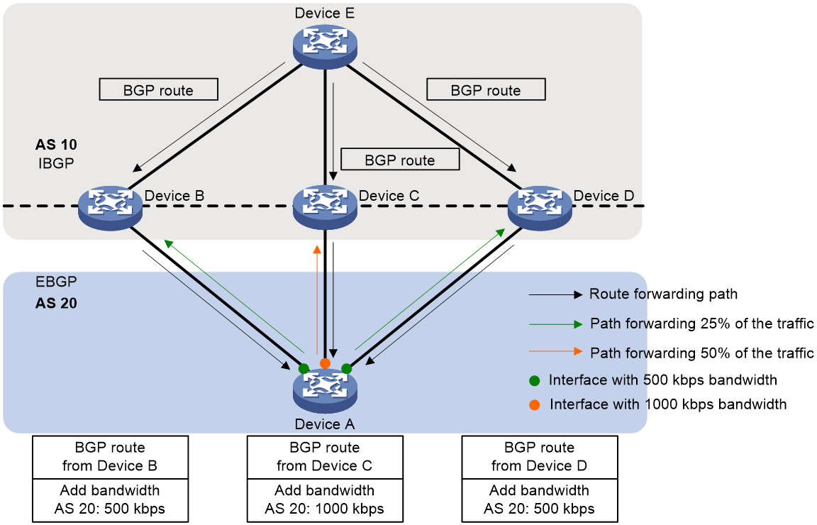
By default, the BGP routes with link bandwidth attributes are advertised only to IBGP peers and the added link bandwidth attributes are optional non-transitive attributes. You can change the advertisement rule for BGP routes with link bandwidth attributes as needed:
· To advertise link bandwidth attributes to EBGP peers, execute the peer advertise ebgp bandwidth command.
· To make BGP peers that cannot identify link bandwidth attributes to carry link bandwidth attributes when they forward BGP routes, execute the peer advertise bandwidth transitive command. This command can convert the link bandwidth attributes carried in BGP routes into optional transitive attributes.
Restrictions and guidelines
When you configure this feature to add link bandwidth attributes to BGP routes, follow these restrictions and guidelines:
· This feature applies only to direct EBGP peers or peer groups. If the specified peer or peer group becomes an indirectly connected neighbor, the device no longer adds link bandwidth attributes to the routes received from that neighbor.
· Only if all BGP routes for the same destination address carry the link bandwidth attributes, can these routes provide UCMP load balancing. Otherwise, the routes can only provide ECMP load balancing.
· A BGP route can carry a maximum of one link bandwidth attribute. If a received route already has a link bandwidth attribute, the device cannot add a link bandwidth attribute to the route any more.
In advertisement of BGP routes with link bandwidth attributes, the following restrictions apply:
· If you use the peer route-policy export command to apply a routing policy to a BGP peer/peer group, and the routing policy uses the apply extcommunity command to configure a link bandwidth attribute for BGP routes, that link bandwidth attribute will be carried in the BGP routes advertised to the BGP peer/peer group.
· When the device receives a BGP route with a link bandwidth attribute, the device deletes the link bandwidth attribute before advertising the route if the next hop address of the route needs to be changed before advertisement. This is because the forwarding link instructed by this route has changed and thus the carried link bandwidth no longer indicates the bandwidth of the actual forwarding link. This restriction does not exist if the device receives a route without a link bandwidth attribute and then adds a link bandwidth attribute to the route.
· For UCMP routes, if the Add-Path feature is configured to advertise only one optimal route, the optimal route advertised will carry a link bandwidth attribute that is the total link bandwidth of all UCMP routes. If the Add-Path feature is configured to advertise more than one optimal route, the advertised routes carry their respective link bandwidth attributes.
Procedure
1. Enter system view.
system-view
2. Enter BGP VPNv4 address family view or BGP-VPN VPNv4 address family view.
¡ Execute the following commands in sequence to enter BGP VPNv4 address family view:
bgp as-number [ instance instance-name ]
address-family vpnv4
¡ Execute the following commands in sequence to enter BGP-VPN VPNv4 address family view:
bgp as-number [ instance instance-name ]
ip vpn-instance vpn-instance-name
address-family vpnv4
3. Configure a link bandwidth attribute for a peer or peer group.
peer { group-name | ipv4-address [ mask-length ] } bandwidth [ bandwidth-value ]
By default, no link bandwidth attribute is configured for a peer or peer group.
4. (Optional.) Configure the device to advertise link bandwidth attributes to EBGP peers.
peer { group-name | ipv4-address [ mask-length ] } advertise ebgp bandwidth
By default, the device does not advertise link bandwidth attributes to EBGP peers.
5. (Optional.) Convert the link bandwidth attributes to optional transitive attributes in the BGP routes to be advertised to a peer or peer group.
peer { group-name | ipv4-address [ mask-length ] } advertise bandwidth transitive
By default, the link bandwidth attributes in BGP routes are optional non-transitive attributes.
Enabling independent routing tables for BGP VPNv4 routes and BGP-VPN instance routes
About this task
After the undo policy vpn-target command is executed, VPNv4 routes without matching route targets of the local VPN instance can be received. If the VPNv4 routes have the same RD as the local VPN instance, these routes can be selected in the BGP VPNv4 routing table as optimal routes. However, routes without matching route targets are invisible and unavailable in the BGP-VPN instance routing table and cannot be added to the routing table of the VPN instance. The BGP-VPN instance routing table uses the same optimal route selection result as the BGP VPNv4 routing table. Therefore, if a route without matching route targets is selected as the only optimal route in the BGP VPNv4 routing table, no optimal route can be added to the BGP-VPN instance routing table. Only the optimal route in the BGP-VPN instance routing table can be added to the VPN instance IP routing table. Therefore, the BGP route without matching route targets cannot be added to the VPN instance IP routing table, so packets destined for the destination address of that route cannot be forwarded.
You can configure this feature (the routing-table independent enable command) to resolve this issue. After this feature is enabled, only BGP VPNv4 optimal routes with matching route targets of a VPN instance can be added to the corresponding BGP-VPN instance routing table. These routes can participate in optimal route selection together with other routes in the BGP-VPN instance routing table and the selection result is independent of that in the BGP VPNv4 routing table. This mechanism allows the BGP-VPN instance routing table to contain only the BGP routes with matching route targets of the corresponding VPN instance. So the optimal routes selected in the BGP-VPN instance routing table can always be added to the VPN instance IP routing table.
For example, a PE has learned two routes with the same prefix (10.10.10.10/32) and different next hops through BGP VPNv4 sessions.
<Sysname> display bgp routing-table vpnv4
BGP local router ID is 2.2.2.2
Status codes: * - valid, > - best, d - dampened, h - history,
s - suppressed, S - stale, i - internal, e - external,
a - additional-path
Origin: i - IGP, e - EGP, ? - incomplete
Total number of routes from all PEs: 2
Route distinguisher: 10:1(vpn1)
Total number of routes: 3
Network NextHop MED LocPrf PrefVal Path/Ogn
* >i 10.10.10.10/32 1.1.1.1 0 100 0 i
* i 3.3.3.3 0 100 0 i
Route distinguisher: 20:1
Total number of routes: 1
Network NextHop MED LocPrf PrefVal Path/Ogn
* >i 10.10.10.10/32 3.3.3.3 0 100 100 i
|
|
NOTE: In the BGP VPNv4 routing table, route entries are listed by RD. In the previous output, the BGP VPNv4 routing table contains two route lists, one for RD 10:1 and the other for RD 20:1. |
The route with next hop address 3.3.3.3 has matching route target values of VPN instance vpn1, while the route with next hop address 1.1.1.1 does not. The route with next hop 3.3.3.3 is added to the BGP-VPN instance routing table of vpn1. The BGP VPNv4 of RD 10:1 and the BGP-VPN instance share the same route entries, so the BGP VPNv4 routing table for RD 10:1 also contains the route with next hop 3.3.3.3. In the BGP VPNv4 routing table for RD 10:1, the route with next hop 3.3.3.3 and the route with next hop 1.1.1.1 participate in optimal route selection and the route with next hop 1.1.1.1 is selected as the optimal route. However, the route target attribute of the route with next hop 1.1.1.1 does not match that of vpn1, so this route is not available in the BGP-VPN instance routing table of vpn1. As a result, there is no optimal route destined for 10.10.10.10/32 in the BGP-VPN instance routing table of vpn1.
<Sysname> display bgp routing-table ipv4 vpn-instance vpn1
Total number of routes: 1
BGP local router ID is 2.2.2.2
Status codes: * - valid, > - best, d - dampened, h - history,
s - suppressed, S - stale, i - internal, e - external,
a - additional-path
Origin: i - IGP, e - EGP, ? - incomplete
Network NextHop MED LocPrf PrefVal Path/Ogn
* i 10.10.10.10/32 3.3.3.3 0 100 100 i
After this feature is configured, the BGP VPNv4 routing table and the BGP-VPN instance routing table no longer share route entries. The BGP VPNv4 routing table is as follows:
<Sysname> display bgp routing-table vpnv4
BGP local router ID is 2.2.2.2
Status codes: * - valid, > - best, d - dampened, h - history,
s - suppressed, S - stale, i - internal, e - external,
a - additional-path
Origin: i - IGP, e - EGP, ? - incomplete
Total number of routes from all PEs: 2
Route distinguisher: 10:1(vpn1)
Total number of routes: 3
Network NextHop MED LocPrf PrefVal Path/Ogn
* >i 10.10.10.10/32 1.1.1.1 0 100 0 i
Route distinguisher: 20:1
Total number of routes: 1
Network NextHop MED LocPrf PrefVal Path/Ogn
* >i 10.10.10.10/32 3.3.3.3 0 100 100 i
The route with next hop 1.1.1.1 is selected as the optimal route for RD 10:1. However, the route target attribute of the route with next hop 1.1.1.1 does not match that of vpn1, so this route cannot be added to the BGP-VPN instance routing table of vpn1.
The route with next hop 3.3.3.3 is selected as the optimal route for RD 20:1, and the route target attribute of the route matches that of vpn1. So this route can be added to the BGP-VPN instance routing table of vpn1 and selected as an optimal route and thus added to the IP routing table of vpn1.
<Sysname> display bgp routing-table ipv4 vpn-instance vpn1
Total number of routes: 1
BGP local router ID is 2.2.2.2
Status codes: * - valid, > - best, d - dampened, h - history,
s - suppressed, S - stale, i - internal, e - external,
a - additional-path
Origin: i - IGP, e - EGP, ? - incomplete
Network NextHop MED LocPrf PrefVal Path/Ogn
* >i 10.10.10.10/32 3.3.3.3 0 100 100 i
IP prefix routes can be added to a BGP-VPN instance routing table. When the optimal route for an IP prefix in the VPNv4 address family does not match the route targets of the local VPN instance, this feature also can add the route with the same IP prefix learned from the BGP EVPN address family to the BGP-VPN instance routing table. The IP prefix advertisement route added to the BGP-VPN instance routing table can be selected as an optimal route and added to the IP routing table of the VPN instance.
This feature also provides the following function:
· Before this feature is enabled, the peer re-originated command cannot modify the route information for received BGP VPNv4 routes that have the same RD as the local VPN instance.
· After this feature is enabled, the peer re-originated command can modify the route information for all received BGP VPNv4 routes.
Restrictions and guidelines
The bestroute same-rd command and the routing-table independent enable command can implement similar functions. The differences include the following:
· The bestroute same-rd command ignores the routes that do not have matching route targets of the local VPN instance, and enables BGP to add other routes that have the same IP prefix and matching route targets (if any in the BGP VPNv4 routing table) to the IP routing table of the VPN instance.
· The routing-table independent enable command uses the routes learned from other BGP routing tables to implement the function of adding BGP routes to the IP routing table of the VPN instance. In the BGP VPNv4 routing table for an RD, the route without matching route targets still cannot be added to the IP routing table of the VPN instance. This feature applies to the following scenarios:
¡ There are optimal routes with the same IP prefix in the BGP VPNv4 route entries for different RDs.
¡ An IP prefix advertisement route in the BGP EVPN routing table and a VPNv4 route in the BGP VPNv4 routing table have the same IP prefix.
¡ The peer re-originated command is configured to modify the route information for received BGP VPNv4 routes that have the same RD as the local VPN instance.
After the routing-table independent enable command is executed, the bestroute same-rd command no longer takes effect.
Procedure
1. Enter system view.
system-view
2. Enter BGP instance view.
bgp as-number [ instance instance-name ]
3. Enabling independent routing tables for BGP VPNv4 routes and BGP-VPN instance routes.
routing-table independent enable
By default, BGP VPNv4 routes and BGP-VPN routes share the same route entries. The BGP routes in BGP-VPN instance routing table can also be displayed in the BGP VPNv4 routing table. For the same VPN instance, it has the same optimal route selection result in BGP VPNv4 routing table and in the BGP-VPN instance routing table.
Configuring the rule for adding BGP routes to the IP routing table and the route advertisement rule for VPN instances
About this task
Perform this task to configure the following features:
· Route adding rule—For multiple BGP routes to the same destination, BGP adds the optimal route with matching route targets of a VPN instance to the IP routing table of the VPN instance.
After the undo policy vpn-target command is executed, VPNv4 routes without matching route targets of the local VPN instance can be received. If the VPNv4 routes have the same RD as the local VPN instance, these routes can be selected in the BGP VPNv4 routing table as optimal routes. However, routes without matching route targets are invisible and unavailable in the BGP-VPN instance routing table and cannot be added to the routing table of the VPN instance. The BGP-VPN instance routing table uses the same optimal route selection result as the BGP VPNv4 routing table. Therefore, if a route without matching route targets is selected as the only optimal route in the BGP VPNv4 routing table, no optimal route can be added to the BGP-VPN instance routing table. Only the optimal route in the BGP-VPN instance routing table can be added to the VPN instance IP routing table. Therefore, the BGP route without matching route targets cannot be added to the VPN instance IP routing table, so packets destined for the destination address of that route cannot be forwarded.
You can configure this feature to resolve this issue. With this feature configured, for BGP routes to the same destination address, BGP adds the optimal route with the same route targets as a VPN instance to the IP routing table of the VPN instance.
For example, the import target of VPN instance vpna is 10:1. The BGP routing table of VPN instance vpna contains two routes to destination address 1.1.1.1, which are 1.1.1.1 <RT: 10:1> and 1.1.1.1 <RT: 20:1>, and 1.1.1.1 <RT: 20:1> is the optimal route. After you configure this feature, BGP will add 1.1.1.1 <RT: 10:1> to the IP routing table of VPN instance vpna, because this route has the same import target as the VPN instance.
· Route advertisement rule—When the optimal route to a destination address cannot be advertised to peers, the device advertises the suboptimal route to the destination address from the routes that can be advertised. The device does not advertise any route for a destination address only if no routes to the destination address can be advertised.
The BGP routing table of a VPN instance contains the routes in the IP routing table of the VPN instance, so the routing table of a BGP address family might contain routes that are not learned from that address family. For example, an IP prefix advertisement route learned from the BGP EVPN address family is added to the IP routing table of a VPN instance, and the route also exists in the BGP routing tables of the BGP-VPN IPv4 unicast address family and BGP VPNv4 address family in the VPN instance. BGP cannot advertise the optimal route to peers in an address family if the optimal route is not learned from that address family, making the destination address of the route unreachable.
After you configure this feature, if the optimal route to a destination address cannot be advertised to peers, the device advertises the suboptimal route, and so forth until a route to the destination address is advertised successfully. The device does not advertise any route for a destination address only if no routes to the destination address can be advertised.
For example, the device learns the route with IP prefix 3.3.3.3/32 from both the BGP VPNv4 address family and the BGP EVPN address family. Therefore, there will be two routes to destination address 3.3.3.3 in the BGP routing table of the BGP VPNv4 address family, and the one learned from the BGP EVPN address family is the optimal route. However, this optimal route cannot be advertised to BGP VPNv4 peers, because it was learned from the BGP EVPN address family. As a result, network nodes deployed with only BGP VPNv4 cannot obtain the route with IP prefix 3.3.3.3/32. After you configure this feature, the device will advertise the route with IP prefix 3.3.3.3/32 learned from the BGP VPNv4 address family to BGP VPNv4 peers, although this route is not the optimal route.
Restrictions and guidelines
The bestroute same-rd command takes effect on BGP routes of all VPN instances. Use caution when you execute this command.
After the routing-table independent enable command is executed, the bestroute same-rd command no longer takes effect. For more information about the differences of the two commands, see "Enabling independent routing tables for BGP VPNv4 routes and BGP-VPN instance routes."
Procedure
1. Enter system view.
system-view
2. Enter BGP instance view.
bgp as-number [ instance instance-name ]
3. Configure BGP to add the optimal routes with the same route targets as a VPN instance to the IP routing table of the VPN instance, and allow BGP to advertise non-optimal routes in the BGP VPN instance to its peers.
bestroute same-rd
By default, BGP adds the optimal routes in the BGP routing table to the IP routing table of a VPN instance and advertises only the optimal routes to its peers.
Minimizing the priority of BGP routes advertised to peers
Minimizing the priority of BGP routes advertised to peers with a down-to-up state change
About this task
By default, the device sends BGP routes immediately to a peer when the peer state changes to Up. If the device advertises routes before completing ARP table convergence, the traffic matching these advertised routes might not be forwarded correctly, which causes traffic loss.
To resolve this issue, use this feature to minimize the priority of the routes to be advertised after the state of a peer changes from Down to Up. The peer will not select the routes received from the device as the optimal routes. After the ARP table convergence is completed and the specified wait time elapses, the device restores the priority of the routes advertised to the peer.
After you use this feature, the device performs the following tasks when the state of a peer changes from Down to Up:
· Sets the local preference value to the minimum (0) and the MED value to the maximum (4294967295) for the routes to be advertised.
· After the specified wait time elapses, restores the local preference value and the MED value for the advertised routes, and then advertises these routes immediately.
For the device to restore the priority of the advertised routes before the specified wait time elapses, use one of the following commands:
¡ reset bgp advertise lowest-priority on-peer-up
After you use this command, the device immediately sends BGP routes with the original local preference value and MED value to the peer. If the state of a peer changes from Down to Up later, the device still minimizes the priority of the routes advertised to that peer.
¡ undo advertise lowest-priority on-peer-up duration
After you use this command, the device immediately sends BGP routes with the original local preference value and MED value to the peer. The device does not change the original local preference value and MED value for the subsequent routes advertised to peers.
Restrictions and guidelines
You can use the advertise lowest-priority on-peer-up duration command multiple times to change the wait time. After you change the wait time, the following rules apply:
· If the original wait time setting is taking effect, the new wait time setting will immediately take over and the device will update the time to wait for route priority restoration.
For example, you can set the wait time to 10 seconds by using the advertise lowest-priority on-peer-up duration 10 command. Then, you use the advertise lowest-priority on-peer-up duration 6 command to set a new wait time six seconds after the state of a peer changes from Down to Up. The device will still minimize the priority of the routes advertised to the peer during the following six seconds.
· If the original wait time is not taking effect, the new wait time will take effect after the state of a peer changes from Down to Up.
The following commands can influence each other:
· advertise lowest-priority on-peer-up duration
· advertise lowest-priority on-startup duration
· bgp update-delay on-startup
· route-update-delay
When you use two of the commands above together, the configuration result varies by command as follows:
|
Command A |
Command B |
Configuration result |
|
bgp update-delay on-startup |
advertise lowest-priority on-startup duration in the view of a BGP address family |
In the address family configured with command B, only command B takes effect. In the address families not configured with command B, command A takes effect. |
|
advertise lowest-priority on-peer-up duration in the view of a BGP address family |
Assume that the delay time specified in command A is TA and the wait time specified in command B is TB. In the address families not configured with command B, only command A takes effect. In the address family configured with command B, the two commands take effect as follows after the device restarts and the BGP process recovers: · If TA ≥ TB, only command A takes effect. · If TA < TB, the device performs the following tasks: ¡ The device does not send any BGP routes to peers within TA. ¡ The device sends BGP routes to peers and minimizes the priority of these routes during the remaining time (TB minus TA). ¡ After TB elapses, the device restores the priority of the advertised routes, and then immediately sends them to peers. The device does not minimize the priority of the subsequent routes advertised to peers. |
|
|
route-update-delay |
advertise lowest-priority on-startup duration in BGP VPNv4 or BGP-VPN VPNv4 address family view |
In BGP VPNv4 or BGP-VPN VPNv4 address family view, the two commands take effect as follows after the device restarts and the BGP process recovers: · If TS ≥ TB, only command A takes effect. · If TS < TB, the device performs the following tasks: a. The device does not send any BGP routes to peers within TS. b. After TS elapses, the device sends BGP routes to peers and minimizes the priority of these routes during the remaining time (TB minus TS). c. After TB elapses, the device restores the priority of the advertised routes, and then immediately sends them to peers. The device does not minimize the priority of the subsequent routes advertised to peers. TB represents the wait time specified in command B. TS represents the larger interval among the intervals specified in the peer route-update-interval command and command A. If you did not execute the peer route-update-interval command for the peers, the device uses the default value of this command to compare with the interval configured in command A. |
|
advertise lowest-priority on-peer-up duration in BGP VPNv4 or BGP-VPN VPNv4 address family view |
In BGP VPNv4 or BGP-VPN VPNv4 address family view, the two commands take effect as follows after the state of a peer changes from Down to Up: · If TS ≥ TB, only command A takes effect. · If TS < TB, the device performs the following tasks: a. The device does not send any BGP routes to peers within TS. b. After TS elapses, the device sends BGP routes to peers and minimizes the priority of these routes during the remaining time (TB minus TS). c. After TB elapses, the device restores the priority of the advertised routes, and then immediately sends them to the peer. The device does not minimize the priority of the subsequent routes advertised to the peer. TB represents the wait time specified in command B. TS represents the larger interval among the intervals specified in the peer route-update-interval command and command A. If you did not execute the peer route-update-interval command for the peers, the device uses the default value of this command to compare with the interval configured in command A. |
|
|
advertise lowest-priority on-peer-up duration in the view of a BGP address family |
advertise lowest-priority on-startup duration in the view of a BGP address family |
Command A is mutually exclusive with command B in the same address family. |
For more information about the following commands, see basic BGP commands in Layer 3—IP Routing Command Reference:
· advertise lowest-priority on-peer-up duration
· advertise lowest-priority on-startup duration
· peer route-update-interval
· route-update-delay
· bgp update-delay on-startup
Procedure
1. Enter system view.
system-view
2. Enter BGP VPNv4 address family view or BGP-VPN VPNv4 address family view.
¡ Execute the following commands in sequence to enter BGP VPNv4 address family view:
bgp as-number [ instance instance-name ]
address-family vpnv4
¡ Execute the following commands in sequence to enter BGP-VPN VPNv4 address family view:
bgp as-number [ instance instance-name ]
ip vpn-instance vpn-instance-name
address-family vpnv4
3. Minimize the priority of the routes advertised to a peer after the peer state changes from Down to Up.
advertise lowest-priority on-peer-up duration seconds
By default, BGP does not change the priority of the routes advertised to its peers.
Minimizing the priority of BGP routes advertised to peers after a device reboot
About this task
By default, the device sends BGP routes immediately to peers after the device restarts and the BGP process recovers. If the device advertises routes before completing ARP table convergence, the traffic matching these advertised routes might not be forwarded correctly, which causes traffic loss.
To resolve this issue, use this feature to minimize the priority of the routes to be advertised after the device restarts and the BGP process recovers. Peers will not select the routes received from the device as the optimal routes. After the ARP table convergence is completed and the specified wait time elapses, the device restores the priority of the routes advertised to the peers.
After you use this feature, the device performs the following tasks after the device restarts and the BGP process recovers:
1. Set the local preference value to the minimum (0) and the MED value to the maximum (4294967295) for the routes to be advertised.
2. After the specified wait time elapses, restore the local preference value and the MED value for the advertised routes, and then advertise these routes immediately.
For the device to restore the priority of the advertised routes before the specified wait time elapses, use one of the following commands:
¡ reset bgp advertise lowest-priority on-startup
After you use this command, the device immediately sends BGP routes with the original local preference value and MED value to peers. The device does not minimize the priority of the subsequent routes advertised to the peers unless the device restarts again.
¡ undo advertise lowest-priority on-startup duration
After you use this command, the device immediately sends BGP routes with the original local preference value and MED value to peers. The device does not change the original local preference value and MED value for the subsequent routes advertised to the peers.
Restrictions and guidelines
The configuration of the advertise lowest-priority on-startup duration command does not take effect immediately. It takes effect only after the device restarts.
The following commands can influence the configuration of each other:
· advertise lowest-priority on-peer-up duration
· advertise lowest-priority on-startup duration
· bgp update-delay on-startup
· route-update-delay
When you use two of the commands above together, the configuration result varies by command. For more information, see Table 1.
For more information about the following commands, see basic BGP commands in Layer 3—IP Routing Command Reference:
· advertise lowest-priority on-peer-up duration
· advertise lowest-priority on-startup duration
· peer route-update-interval
· route-update-delay
· bgp update-delay on-startup
Procedure
1. Enter system view.
system-view
2. Enter BGP VPNv4 address family view or BGP-VPN VPNv4 address family view.
¡ Execute the following commands in sequence to enter BGP VPNv4 address family view:
bgp as-number [ instance instance-name ]
address-family vpnv4
¡ Execute the following commands in sequence to enter BGP-VPN VPNv4 address family view:
bgp as-number [ instance instance-name ]
ip vpn-instance vpn-instance-name
address-family vpnv4
3. Minimize the priority of the routes advertised to peers after the device restarts and the BGP process recovers.
advertise lowest-priority on-startup duration seconds
By default, BGP does not change the priority of the routes advertised to its peers.
Restoring the priority of advertised BGP routes
About this task
After configuring the device to minimize the priority of BGP routes sent to a peer within the specified time after the device restarts or after the peer state changes from down to up, you can perform this task to manually restore the priority of BGP routes. After you configure this feature, the device restores the priority of BGP routes sent to peers whose timers have not expired and immediately sends the routes to those peers. However, the device still minimizes the priority of BGP routes sent to a peer after the peer comes up or after the device restarts.
Before performing this task, make sure the following conditions exist:
· The device is ready to advertise routes with original priority.
· The advertise lowest-priority on-peer-up duration or advertise lowest-priority on-startup duration command still takes effect after a peer comes up or the device restarts.
After you perform this task, the device immediately sends BGP routes with the original local preference value and MED value to peers.
· If the state of a peer changes from Down to Up later, the device still minimizes the priority of the routes advertised to that peer.
· If the device restarts again later, the device still minimizes the priority of the routes advertised to peers.
Procedure
To restore the priority of advertised BGP routes, execute the following command in user view:
reset bgp [ instance instance-name ] advertise lowest-priority { on-peer-up | on-startup }
Specifying a local network to be advertised in the public instance or a VPN instance
About this task
This feature specifies a local network of the public instance or a VPN instance. Then, you can configure BGP to redistribute the network (by using the import-route local-aggregate command) and advertise the network. For more information about the import-route local-aggregate command, see BGP commands in Layer 3—IP Routing Command Reference.
Restrictions and guidelines
The specified local network route must exist and be active in the routing table of the public instance or VPN instance.
Procedure
1. Enter system view.
system-view
2. Enter public instance IPv4 address family view or VPN instance IPv4 address family view.
¡ Execute the following commands in sequence to enter public instance IPv4 address family view:
ip public-instance
address-family ipv4
¡ Execute the following commands in sequence to enter VPN instance IPv4 address family view:
ip vpn-instance vpn-instance-name
address-family ipv4
3. Specify a local network to be advertised.
network ipv4-address [ mask-length | mask ]
By default, no local network in the public instance or a VPN instance will be advertised.
Configuring route replication
Configuring the public instance
About this task
Configure the public instance to enable the mutual access between public network and private network users.
Restrictions and guidelines
In an MPLS L3VPN network, for the public network and the VPN network to communicate with each other through route target matching, perform the following tasks:
· Configure matching route targets for the public instance and VPN instance.
· Use the route-replicate enable command in BGP instance view to enable mutual BGP route replication between the public and VPN instances.
Procedure
1. Enter system view.
system-view
2. Enter public instance view.
ip public-instance
3. Configure an RD for the public instance.
route-distinguisher route-distinguisher
By default, no RD is configured for the public instance.
4. Configure a route target for the public instance.
vpn-target vpn-target&<1-8> [ both | export-extcommunity | import-extcommunity ]
By default, no route target is configured for the public instance.
5. Apply an import routing policy to the public instance.
import route-policy route-policy
By default, all routes matching the import target attribute are accepted.
6. Apply an export routing policy to the public instance.
export route-policy route-policy
By default, routes to be advertised are not filtered.
7. Enter public instance IPv4 address family view.
address-family ipv4
8. Configure a route target for the IPv4 address family of the public instance.
vpn-target vpn-target&<1-8> [ both | export-extcommunity | import-extcommunity ]
By default, no route target is configured for the IPv4 address family of thee public instance.
9. Apply an import routing policy to the public instance IPv4 address family.
import route-policy route-policy
By default, all routes matching the import target attribute are accepted.
10. Apply an export routing policy to the public instance IPv4 address family.
export route-policy route-policy
By default, routes to be advertised are not filtered.
Configuring route replication for public and VPN instances
About this task
In a BGP/MPLS L3VPN network, only VPN instances that have matching route targets can communicate with each other.
The route replication feature provides the following functions:
· Enables a VPN instance to communicate with the public network or other VPN instances by replicating routes from the public instance or other VPN instances.
· Enables the public network to communicate with a VPN instance by replicating routes from the VPN instance to the public instance.
In an intelligent traffic control network, traffic of different tenants is assigned to different VPNs. To enable the tenants to communicate with the public network, configure this feature to replicate routes from the public network to the VPN instances.
VLINK direct routes are generated based on ARP entries learned by interfaces. The route-replicate from vpn-instance protocol direct or route-replicate from public protocol direct command replicates VLINK direct routes, but the VLINK direct routes cannot be added to the FIB, causing traffic forwarding failures. To address this issue, you can specify the vlink-direct keyword to replicate VLINK direct routes and add the routes to the FIB.
Configuring a VPN instance to replicate routes from the public instance or another VPN instance
1. Enter system view.
system-view
2. Enter VPN instance view.
ip vpn-instance vpn-instance-name
3. Enter VPN instance IPv4 address family view.
address-family ipv4
4. Replicate routes from the public instance or other VPN instances.
route-replicate from { public | vpn-instance vpn-instance-name } protocol { bgp as-number | direct | static | unr | vlink-direct | { isis | ospf | rip } process-id } [ advertise ] [ route-policy route-policy-name ]
route-replicate from { public | vpn-instance vpn-instance-name } protocol eigrp eigrp-as [ advertise ] [ route-policy route-policy-name ]
By default, a VPN instance cannot replicate routes from the public instance or other VPN instances.
Replicating routes from a VPN instance to the public instance
1. Enter system view.
system-view
2. Enter public instance view.
ip public-instance
3. Enter public instance IPv4 address family view.
address-family ipv4
4. Replicate routes from a VPN instance to the public instance.
route-replicate from vpn-instance vpn-instance-name protocol { bgp as-number | direct | static | unr | vlink-direct | { isis | ospf | rip } process-id } [ advertise ] [ route-policy route-policy-name ]
By default, the public instance cannot replicate routes from VPN instances.
Configuring BGP route replication between public and VPN instances
About this task
In a BGP/MPLS L3VPN network, only VPN instances that have matching route targets can communicate with each other.
In traffic cleaning scenarios, traffic between the public and private networks are filtered by firewalls and traffic of different tenants is assigned to different VPNs. To enable the tenants to communicate with the public network under the protection of firewalls, you can configure BGP route replication between public and VPN instances.
After you configure this feature, the public and VPN instances replicate all BGP routes including route attributes from each other.
Restrictions and guidelines
This feature also enables BGP route replication between VPN instances, so VPNs cannot be isolated. Configure this feature only in specific scenarios, for example, the traffic cleaning scenario.
To use this feature to implement IPv4 or IPv6 route replication between the public instance and a VPN instance, make sure the VPN instance and the BGP IPv4 or IPv6 address family have been created.
Procedure
1. Enter system view.
system-view
2. Enter BGP instance view.
bgp as-number [ instance instance-name ]
3. Enable BGP route replication between public and VPN instances.
route-replicate enable
By default, BGP route replication between public and VPN instances is disabled.
Configuring route re-origination
About this task
By default, BGP routes in different VPN instances are isolated. In some networks, a device might need to advertise routes across VPN instances or advertise the routes in a VPN instance through other VPN instances to hide the routing information of the VPN instance.
Figure 25 Route re-origination

As shown in Figure 25, PE 1 and PE 2 set up public IBGP sessions with PE 3, and the public instance and VPN instances exchange routes to enable communication between the public network and the VPN sites. PE 1 and PE 2 set up VPNv4 IBGP peer relationships with each other to exchange VPN instance routes. When all links operate correctly, PE 2 receives the public routes advertised by PE 3 and redistributes the routes to the local VPN site. When the link between PE 2 and PE 3 fails, perform the following tasks for PE 1 to reoriginate the public routes in a specified VPN instance and advertise them to PE 2:
1. Configure route targets for the public instance on PE 1. Make sure the route targets match those of the VPN instance to redistribute public routes.
2. Execute the route-replicate enable command on PE 1 to redistribute the BGP routes of the public instance to the target VPN instance.
3. Execute the advertise route-reoriginate command on PE 1 to enable reoriginating the BGP routes of other VPN instances in the target VPN instance. This command enables reoriginating BGP routes based on only the BGP routes that match the route targets of the target VPN instance. The VPN instance does not reoriginate BGP routes based on the redistributed local routes, such as the IGP routes redistributed by using the import-route command.
4. Execute the peer advertise vpn-reoriginate ibgp command on PE 1 to advertise reoriginated routes to IBGP peer PE 2.
Restrictions and guidelines
You must use the peer advertise vpn-reoriginate ibgp command in combination with the advertise route-reoriginate command. If you execute only the peer advertise vpn-reoriginate ibgp command, it does not take effect.
Procedure
1. Enter system view.
system-view
2. Enter BGP instance view.
bgp as-number [ instance instance-name ]
3. (Optional.) Enable BGP route replication between public and VPN instances.
route-replicate enable
By default, BGP route replication between public and VPN instances is disabled.
4. Enter BGP-VPN instance view.
ip vpn-instance vpn-instance-name
5. Enter BGP-VPN IPv4 unicast address family view.
address-family ipv4 [ unicast ]
6. Re-originate BGP unicast routes from other VPN instances.
advertise route-reoriginate [ route-policy route-policy-name ] [ replace-rt ]
By default, a VPN instance cannot re-originate BGP unicast routes from other VPN instances.
This command enables reoriginating BGP routes based on only the BGP routes that match the route targets of the current VPN instance. The VPN instance does not reoriginate BGP routes based on the redistributed local routes.
7. (Optional.) Enable advertising the BGP routes reoriginated for a VPN instance to an IBGP peer or peer group.
a. Return to BGP instance view.
quit
quit
b. Enter BGP VPNv4 address family view.
address-family vpnv4
c. Enable advertising the BGP routes reoriginated for a VPN instance to an IBGP peer or peer group.
peer { group-name | ipv4-address [ mask-length ] | ipv6-address [ prefix-length ] } advertise vpn-reoriginate ibgp
By default, the device does not advertise the BGP routes reoriginated for a VPN instance to IBGP peers or peer groups.
Enabling a VPN instance to use the public instance routing table for packet forwarding
About this task
If a route redistributed from the public instance to a VPN instance is invalid or unreachable, packet loss might occur. To resolve this issue, perform the following tasks:
1. Configure a default route in the public instance.
2. Configure this feature to enable the VPN instance to forward a packet based on the public instance routing table if it fails to find a match for the packet in the VPN instance routing table.
Procedure
1. Enter system view.
system-view
2. Enter VPN instance view.
ip vpn-instance vpn-instance-name
3. Enable the VPN instance to forward a packet based on the public instance routing table if it fails to find a match for the packet in the VPN instance routing table.
redirect public enable
By default, a VPN instance cannot use the public instance routing table for packet forwarding.
Enabling ECMP VPN route redistribution
About this task
For multiple routes that have the same prefix and RD, a VPN instance redistributes only the optimal route into its routing table by default. This feature enables a VPN instance to redistribute all routes that have the same prefix and RD into its routing table to perform load sharing or MPLS L3VPN FRR.
Procedure
1. Enter system view.
system-view
2. Enter a BGP address family view.
¡ Enter BGP instance view.
bgp as-number [ instance instance-name ]
¡ Execute the following commands in sequence to enter BGP IPv4 unicast address family view.
bgp as-number [ instance instance-name ]
address-family ipv4 [ unicast ]
¡ Execute the following commands in sequence to enter BGP IPv6 unicast address family view.
bgp as-number [ instance instance-name ]
address-family ipv6 [ unicast ]
¡ Execute the following commands in sequence to enter BGP-VPN IPv4 unicast address family view:
bgp as-number [ instance instance-name ]
ip vpn-instance vpn-instance-name
address-family ipv4 [ unicast ]
¡ Execute the following commands in sequence to enter BGP-VPN IPv6 unicast address family view:
bgp as-number [ instance instance-name ]
ip vpn-instance vpn-instance-name
address-family ipv6 [ unicast ]
3. Enable ECMP VPN route redistribution.
vpn-route cross multipath
By default, ECMP VPN route redistribution is disabled. If multiple routes have the same prefix and RD, a VPN instance redistributes only the optimal route into its routing table.
In BGP IPv4 unicast address family view and BGP IPv6 unicast address family view, this command redistributes ECMP routes to the routing table of the public instance. For more information about the public instance, see EVPN Configuration Guide.
Enabling prioritized withdrawal of specific routes
About this task
Configure BGP to send withdrawal messages of specific routes prior to other routes to ensure fast route switchover and reduce the traffic interruption time for the specific routes.
For more information about the commands of this feature, see basic BGP commands in Layer 3—IP Routing Command Reference.
Procedure
1. Enter system view.
system-view
2. Enter BGP instance view.
bgp as-number [ instance instance-name ]
3. Enter BGP VPNv4 address family view.
address-family vpnv4
4. Configure BGP to send withdrawal messages of routes matching the specified routing policy prior to other routes.
update-first route-policy route-policy-name
By default, BGP does not send withdrawal messages of specific routes prior to other routes.
Configuring BGP next hop recursion based on a routing policy
About this task
BGP route recursion without any restrictions might recurse a route to an incorrect forwarding path.
To resolve this issue, you can use a routing policy to control the route recursion results. After you configure this feature, the next hop for a BGP route can be recursed only to a route that is permitted by the routing policy. You can configure various conditions in the routing policy to filter out incorrect routes and ensure that the next hop of a BGP route can be recursed to the expected forwarding path.
If none of the recursive next hops for a BGP route is permitted by the routing policy, the BGP route is marked as unreachable. A BGP route is permitted by a routing policy if it passes the filtering of the permit node in the routing policy.
To not use a routing policy to filter the recursive routes for the BGP routes learned from a specific peer or peer group, you can use the peer nexthop-recursive-policy disable command to disable routing policy-based recursive next hop lookup.
Restrictions and guidelines
The nexthop recursive-lookup route-policy command does not take effect on the routes learned from direct EBGP peers.
In you execute the nexthop recursive-lookup route-policy command in BGP VPNv4 or BGP-VPN VPNv4 address family view and the protocol nexthop recursive-lookup command in RIB IPv4 address family view, the nexthop recursive-lookup route-policy command takes effect on the BGP routes in BGP VPNv4 or BGP-VPN VPNv4 address family view.
If the nexthop recursive-lookup route-policy command is not executed in a BGP address family view but the protocol nexthop recursive-lookup command is executed in RIB IPv4 address family view, the BGP routes in the BGP address family use the protocol nexthop recursive-lookup command settings for recursive next hop lookup.
For more information about the nexthop recursive-lookup route-policy command and the peer nexthop-recursive-policy disable command, see BGP commands in Layer 3—IP Routing Command Reference.
For more information about the protocol nexthop recursive-lookup command, see basic IP routing commands in Layer 3—IP Routing Command Reference.
Procedure
1. Enter system view.
system-view
2. Enter BGP VPNv4 address family view or BGP-VPN VPNv4 address family view.
¡ Execute the following commands in sequence to enter BGP VPNv4 address family view.
bgp as-number [ instance instance-name ]
address-family vpnv4
¡ Execute the following commands in sequence to enter BGP-VPN VPNv4 address family view.
bgp as-number [ instance instance-name ]
ip vpn-instance vpn-instance-name
address-family vpnv4
3. Configure BGP next hop recursion based on a routing policy.
nexthop recursive-lookup route-policy route-policy-name
By default, BGP does not use a routing policy to filter recursive next hop routes.
|
|
CAUTION: After this command is executed, if no recursive next hops for the BGP routes in the address family are permitted by the routing policy, all the BGP routes become unreachable routes. Before you execute this command, make sure the expected recursive next hop route can pass the filtering of the permit node in the specified routing policy. |
4. (Optional.) Disable routing policy-based recursive next hop lookup:
a. Return to BGP instance view or BGP-VPN instance view.
quit
b. Disable routing policy-based recursive next hop lookup for routes learned from the specified peer or peer group.
peer { group-name | ipv4-address [ mask-length ] } nexthop-recursive-policy disable
By default, recursive next hop lookup for routes is controlled by a routing policy.
After you execute this command, the nexthop recursive-lookup route-policy and protocol nexthop recursive-lookup commands do not take effect on the BGP routes learned from the specified peer or peer group.
Configuring a VPN peer
About this task
Two virtual private clouds (VPCs) that communicate with each other through MPLS L3VPN are called VPN peers of each other.
You can configure routes to carry a VPN peer ID by using a routing policy. Packets that match the routes will be processed based on the user profile associated with the VPN peer.
For more information about routing policies, see Layer 3—IP Routing Configuration Guide.
For more information about user profiles, see Security Configuration Guide.
Procedure
1. Enter system view.
system-view
2. Configure a VPN peer.
vpn-peer vpn-peer-name vpn-peer-id vpn-peer-id user-profile profile-name
Enabling SNMP notifications for MPLS L3VPN
About this task
To report critical MPLS L3VPN events to an NMS, enable SNMP notifications for MPLS L3VPN. For MPLS L3VPN event notifications to be sent correctly, you must also configure SNMP on the device. For more information about SNMP configuration, see the network management and monitoring configuration guide for the device.
Procedure
1. Enter system view.
system-view
2. Enable SNMP notifications for MPLS L3VPN.
snmp-agent trap enable l3vpn
By default, SNMP notifications for MPLS L3VPN are enabled.
Enabling logging for BGP route flapping
About this task
This feature enables BGP to generate logs for BGP route flappings that trigger log generation. The generated logs are sent to the information center. For the logs to be output correctly, you must also configure information center on the device. For more information about the information center, see System Management Configuration Guide.
Procedure
1. Enter system view.
system-view
2. Enter BGP VPNv4 address family view or BGP-VPN VPNv4 address family view.
¡ Execute the following commands in sequence to enter BGP VPNv4 address family view:
bgp as-number [ instance instance-name ]
address-family vpnv4
¡ Execute the following commands in sequence to enter BGP-VPN VPNv4 address family view:
bgp as-number [ instance instance-name ]
ip vpn-instance vpn-instance-name
address-family vpnv4
3. Enable logging for BGP route flapping.
log-route-flap monitor-time monitor-count [ log-count-limit | route-policy route-policy-name ] *
By default, logging for BGP route flapping is disabled.
Verifying and maintaining MPLS L3VPN
Verifying MPLS L3VPN configuration and running status
Verifying BGP route configuration
Perform display tasks in any view.
· Display BGP peer and route summary information.
display bgp [ instance instance-name ] vpnv4 summary
For more information about the command, see basic BGP commands in Layer 3—IP Routing Command Reference.
· Display BGP RT filter routing information.
display bgp [ instance instance-name ] routing-table ipv4 rtfilter [ default-rt [ advertise-info | as-path | cluster-list ] | [ origin-as as-number ] [ route-target [ advertise-info | as-path | cluster-list ] ] | peer ipv4-address { advertised-routes | received-routes } [ default-rt | [ origin-as as-number ] [ route-target ] | statistics ] | statistics ]
For more information about the command, see basic BGP commands in Layer 3—IP Routing Command Reference.
· Display BGP VPNv4 routes.
display bgp [ instance instance-name ] routing-table vpnv4 [ [ route-distinguisher route-distinguisher ] [ ipv4-address [ mask-length | mask ] [ longest-match ] | ipv4-address [ mask-length | mask ] advertise-info | ipv4-address [ mask-length | mask ] { as-path | cluster-list | community | ext-community } | [ vpn-instance vpn-instance-name ] peer ipv4-address { advertised-routes | received-routes } [ ipv4-address [ mask-length | mask ] | statistics ] | statistics ]
display bgp [ instance instance-name ] routing-table vpnv4 [ route-distinguisher route-distinguisher ] as-path-acl { as-path-acl-number | as-path-acl-name }
display bgp [ instance instance-name ] routing-table vpnv4 [ route-distinguisher route-distinguisher ] [ statistics ] community [ community-number&<1-32> | aa:nn&<1-32> ] [ internet | no-advertise | no-export | no-export-subconfed ] [ whole-match ]
display bgp [ instance instance-name ] routing-table vpnv4 [ route-distinguisher route-distinguisher ] [ statistics ] community-list { basic-community-list-number | comm-list-name | adv-community-list-number } [ whole-match ]
display bgp [ instance instance-name ] routing-table vpnv4 [ route-distinguisher route-distinguisher ] [ statistics ] ext-community [ bandwidth link-bandwidth-value | color color | rt route-target | soo site-of-origin ]&<1-32> [ whole-match ]
display bgp [ instance instance-name ] routing-table vpnv4 [ same-rd-selected ]
· Display information about dampened BGP VPNv4 routes.
display bgp [ instance instance-name ] routing-table dampened vpnv4
For more information about this command, see basic BGP commands in Layer 3—IP Routing Command Reference.
Verifying BGP peer and peer group configuration
This section only lists the commands for verifying BGP peer and peer group configuration. For more information about the commands, see basic BGP commands in Layer 3—IP Routing Command Reference.
Perform display tasks in any view.
· Display BGP RT filter peer information.
display bgp [ instance instance-name ] peer ipv4 rtfilter [ ipv4-address mask-length | { ipv4-address | group-name group-name } log-info | [ ipv4-address ] verbose ]
· Display BGP VPNv4 peer information.
display bgp [ instance instance-name ] peer vpnv4 [ vpn-instance vpn-instance-name ] [ ipv4-address mask-length | { ipv4-address | group-name group-name } log-info | [ ipv4-address ] verbose ]
· Display BGP RT filter peer group information.
display bgp [ instance instance-name ] group ipv4 rtfilter [ group-name group-name ]
· Display BGP VPNv4 peer group information.
display bgp [ instance instance-name ] group vpnv4 [ vpn-instance vpn-instance-name ] [ group-name group-name ]
Verifying BGP update group configuration
This section only lists the commands for verifying BGP update group configuration. For more information about the commands, see basic BGP commands in Layer 3—IP Routing Command Reference.
Perform display tasks in any view.
· Display BGP IPv4 RT filter address family update group information.
display bgp [ instance instance-name ] update-group ipv4 rtfilter [ ipv4-address ]
· Display BGP VPNc4 address family update group information.
display bgp [ instance instance-name ] update-group vpnv4 [ vpn-instance vpn-instance-name ] [ ipv4-address ]
Verifying incoming label and outgoing label configuration
Perform display tasks in any view.
· Display incoming labels for BGP IPv4 unicast routes.
display bgp [ instance instance-name ] routing-table ipv4 [ unicast ] [ vpn-instance vpn-instance-name ] inlabel
· Display outgoing labels for BGP IPv4 unicast routes.
display bgp [ instance instance-name ] routing-table ipv4 [ unicast ] [ vpn-instance vpn-instance-name ] outlabel
· Display incoming labels for BGP VPNv4 routes.
display bgp [ instance instance-name ] routing-table vpnv4 inlabel
· Display outgoing labels for BGP VPNv4 routes.
display bgp [ instance instance-name ] routing-table vpnv4 outlabel
Verifying BGP IPv4 RT filter configuration
To display BGP IPv4 RT filter information, execute the following command in any view:
display bgp [ instance instance-name ] ipv4 rtfilter [ peer ipv4-address [ statistics ] | statistics ]
For more information about the command, see basic BGP commands in Layer 3—IP Routing Command Reference.
Verifying VPN instance configuration
Perform display tasks in any view.
· Display information about a VPN instance.
display ip vpn-instance [ instance-name vpn-instance-name ]
· Display the routing table for a VPN instance.
display ip routing-table vpn-instance vpn-instance-name [ statistics | verbose ]
For more information about the command, see IP routing basics commands in Layer 3—IP Routing Command Reference.
· Display the FIB of a VPN instance.
display fib vpn-instance vpn-instance-name
For more information about the command, see IP forwarding basics commands in Layer 3—IP Services Command Reference.
· Display FIB entries that match the specified destination IP address in the specified VPN instance.
display fib vpn-instance vpn-instance-name ip-address [ mask-length | mask ]
For more information about the command, see IP forwarding basics commands in Layer 3—IP Services Command Reference.
Verifying VPN peer configuration
To display VPN peer information, execute the following command in any view:
display vpn-peer [ peer-id vpn-peer-id | peer-name vpn-peer-name | verbose ]
Verifying OSPF sham link configuration
To display OSPF sham link information, execute the following command in any view:
display ospf [ process-id ] sham-link [ area area-id ]
Displaying and clearing BGP VPNv4 route dampening parameters
To display BGP VPNv4 route dampening parameters, execute the following command in any view:
display bgp [ instance instance-name ] dampening parameter vpnv4
To clear BGP VPNv4 route dampening information and release dampened routes, execute the following command in user view:
reset bgp [ instance instance-name ] dampening vpnv4 [ ipv4-address [ mask | mask-length ] ]
Displaying and clearing BGP VPNv4 route flapping statistics
To display BGP VPNv4 route flapping statistics, execute the following command in any view:
display ip vpn-instance mpls statistics [ instance-name vpn-instance-name ]
To clear BGP VPNv4 route flapping statistics, execute the following command in user view:
reset bgp [ instance instance-name ] flap-info vpnv4 [ ipv4-address [ mask | mask-length ] | as-path-acl as-path-acl-number | peer ipv4-address [ mask-length ] ]
Resetting BGP sessions
About this task
You can soft-reset or reset BGP sessions to apply new BGP configurations. A soft reset operation updates BGP routing information without tearing down BGP connections. A reset operation updates BGP routing information by tearing down, and then re-establishing BGP connections. Soft reset requires that BGP peers have route refresh capability.
Procedure
The following information only lists the commands for resetting BGP sessions. For more information about the commands, see basic BGP commands in Layer 3—IP Routing Command Reference.
Perform refresh or reset tasks in user view:
· Soft-reset BGP sessions for the BGP IPv4 RT filter address family.
refresh bgp [ instance instance-name ] { ipv4-address [ mask-length ] | all | external | group group-name | internal } { export | import } ipv4 rtfilter
· Soft-reset BGP sessions for the BGP VPNv4 address family.
refresh bgp [ instance instance-name ] { ipv4-address [ mask-length ] | all | external | group group-name | internal } { export | import } vpnv4 [ vpn-instance vpn-instance-name ]
· Reset BGP sessions for the BGP IPv4 RT filter address family.
reset bgp [ instance instance-name ] { as-number | ipv4-address [ mask-length ] | all | external | internal | group group-name } ipv4 rtfilter
· Reset BGP sessions for the BGP VPNv4 address family.
reset bgp [ instance instance-name ] { as-number | ipv4-address [ mask-length ] | all | external | internal | group group-name } vpnv4 [ vpn-instance vpn-instance-name ]
MPLS L3VPN configuration examples
Example: Configuring basic MPLS L3VPN
Network configuration
CE 1 and CE 3 belong to VPN 1. CE 2 and CE 4 belong to VPN 2.
VPN 1 uses route target attribute 111:1. VPN 2 uses route target attribute 222:2. Users of different VPNs cannot access each other.
A PE and its connected CE use EBGP to exchange VPN routing information.
PEs use OSPF to communicate with each other and use MP-IBGP to exchange VPN routing information.
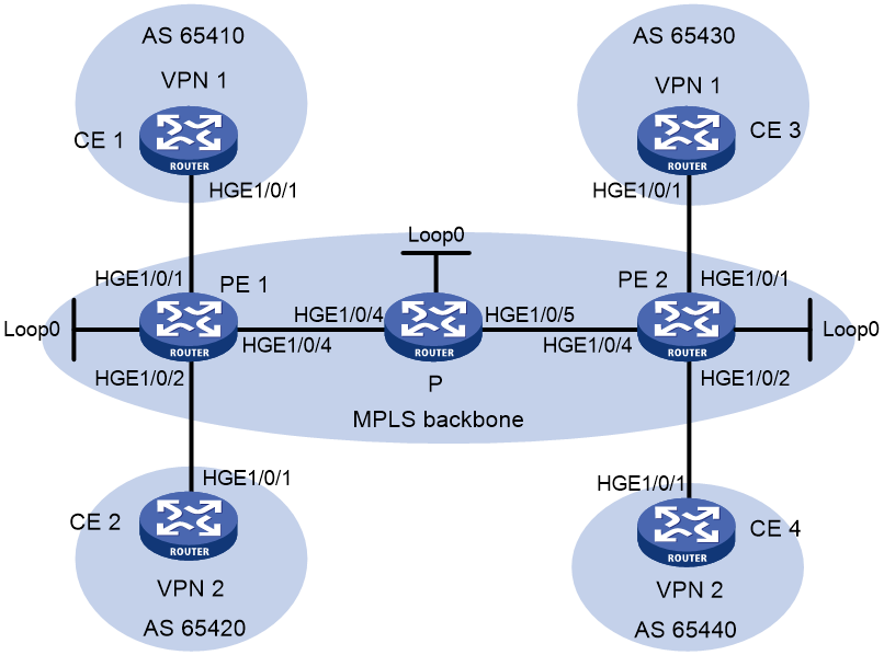
Table 2 Interface and IP address assignment
|
Device |
Interface |
IP address |
Device |
Interface |
IP address |
|
CE 1 |
HGE1/0/1 |
10.1.1.1/24 |
P |
Loop0 |
2.2.2.9/32 |
|
PE 1 |
Loop0 |
1.1.1.9/32 |
|
HGE1/0/4 |
172.1.1.2/24 |
|
|
HGE1/0/1 |
10.1.1.2/24 |
|
HGE1/0/5 |
172.2.1.1/24 |
|
|
HGE1/0/2 |
10.2.1.2/24 |
PE 2 |
Loop0 |
3.3.3.9/32 |
|
|
HGE1/0/4 |
172.1.1.1/24 |
|
HGE1/0/1 |
10.3.1.2/24 |
|
CE 2 |
HGE1/0/1 |
10.2.1.1/24 |
|
HGE1/0/2 |
10.4.1.2/24 |
|
CE 3 |
HGE1/0/1 |
10.3.1.1/24 |
|
HGE1/0/4 |
172.2.1.2/24 |
|
CE 4 |
HGE1/0/1 |
10.4.1.1/24 |
|
|
|
Procedure
1. Configure OSPF on the MPLS backbone to ensure IP connectivity within the backbone:
# Configure PE 1.
<PE1> system-view
[PE1] interface loopback 0
[PE1-LoopBack0] ip address 1.1.1.9 32
[PE1-LoopBack0] quit
[PE1] interface hundredgige 1/0/4
[PE1-HundredGigE1/0/4] ip address 172.1.1.1 24
[PE1-HundredGigE1/0/4] quit
[PE1] ospf
[PE1-ospf-1] area 0
[PE1-ospf-1-area-0.0.0.0] network 172.1.1.0 0.0.0.255
[PE1-ospf-1-area-0.0.0.0] network 1.1.1.9 0.0.0.0
[PE1-ospf-1-area-0.0.0.0] quit
[PE1-ospf-1] quit
# Configure the P device.
<P> system-view
[P] interface loopback 0
[P-LoopBack0] ip address 2.2.2.9 32
[P-LoopBack0] quit
[P] interface hundredgige 1/0/4
[P-HundredGigE1/0/4] ip address 172.1.1.2 24
[P-HundredGigE1/0/4] quit
[P] interface hundredgige 1/0/5
[P-HundredGigE1/0/5] ip address 172.2.1.1 24
[P-HundredGigE1/0/5] quit
[P] ospf
[P-ospf-1] area 0
[P-ospf-1-area-0.0.0.0] network 172.1.1.0 0.0.0.255
[P-ospf-1-area-0.0.0.0] network 172.2.1.0 0.0.0.255
[P-ospf-1-area-0.0.0.0] network 2.2.2.9 0.0.0.0
[P-ospf-1-area-0.0.0.0] quit
[P-ospf-1] quit
# Configure PE 2.
<PE2> system-view
[PE2] interface loopback 0
[PE2-LoopBack0] ip address 3.3.3.9 32
[PE2-LoopBack0] quit
[PE2] interface hundredgige 1/0/4
[PE2-HundredGigE1/0/4] ip address 172.2.1.2 24
[PE2-HundredGigE1/0/4] quit
[PE2] ospf
[PE2-ospf-1] area 0
[PE2-ospf-1-area-0.0.0.0] network 172.2.1.0 0.0.0.255
[PE2-ospf-1-area-0.0.0.0] network 3.3.3.9 0.0.0.0
[PE2-ospf-1-area-0.0.0.0] quit
[PE2-ospf-1] quit
# Execute the display ospf peer command to verify that OSPF adjacencies in Full state have been established between PE 1, P, and PE 2. Execute the display ip routing-table command to verify that the PEs have learned the routes to the loopback interfaces of each other. (Details not shown.)
2. Configure basic MPLS and MPLS LDP on the MPLS backbone to establish LDP LSPs:
# Configure PE 1.
[PE1] mpls lsr-id 1.1.1.9
[PE1] mpls ldp
[PE1-ldp] quit
[PE1] interface hundredgige 1/0/4
[PE1-HundredGigE1/0/4] mpls enable
[PE1-HundredGigE1/0/4] mpls ldp enable
[PE1-HundredGigE1/0/4] quit
# Configure the P device.
[P] mpls lsr-id 2.2.2.9
[P] mpls ldp
[P-ldp] quit
[P] interface hundredgige 1/0/4
[P-HundredGigE1/0/4] mpls enable
[P-HundredGigE1/0/4] mpls ldp enable
[P-HundredGigE1/0/4] quit
[P] interface hundredgige 1/0/5
[P-HundredGigE1/0/5] mpls enable
[P-HundredGigE1/0/5] mpls ldp enable
[P-HundredGigE1/0/5] quit
# Configure PE 2.
[PE2] mpls lsr-id 3.3.3.9
[PE2] mpls ldp
[PE2-ldp] quit
[PE2] interface hundredgige 1/0/4
[PE2-HundredGigE1/0/4] mpls enable
[PE2-HundredGigE1/0/4] mpls ldp enable
[PE2-HundredGigE1/0/4] quit
# Execute the display mpls ldp peer command to verify that LDP sessions in Operational state have been established between PE 1, P, and PE 2. Execute the display mpls ldp lsp command to verify that the LSPs have been established by LDP. (Details not shown.)
3. Configure VPN instances on PEs to allow CE access:
# Configure PE 1.
[PE1] ip vpn-instance vpn1
[PE1-vpn-instance-vpn1] route-distinguisher 100:1
[PE1-vpn-instance-vpn1] vpn-target 111:1
[PE1-vpn-instance-vpn1] quit
[PE1] ip vpn-instance vpn2
[PE1-vpn-instance-vpn2] route-distinguisher 100:2
[PE1-vpn-instance-vpn2] vpn-target 222:2
[PE1-vpn-instance-vpn2] quit
[PE1] interface hundredgige 1/0/1
[PE1-HundredGigE1/0/1] ip binding vpn-instance vpn1
[PE1-HundredGigE1/0/1] ip address 10.1.1.2 24
[PE1-HundredGigE1/0/1] quit
[PE1] interface hundredgige 1/0/2
[PE1-HundredGigE1/0/2] ip binding vpn-instance vpn2
[PE1-HundredGigE1/0/2] ip address 10.2.1.2 24
[PE1-HundredGigE1/0/2] quit
# Configure PE 2.
[PE2] ip vpn-instance vpn1
[PE2-vpn-instance-vpn1] route-distinguisher 200:1
[PE2-vpn-instance-vpn1] vpn-target 111:1
[PE2-vpn-instance-vpn1] quit
[PE2] ip vpn-instance vpn2
[PE2-vpn-instance-vpn2] route-distinguisher 200:2
[PE2-vpn-instance-vpn2] vpn-target 222:2
[PE2-vpn-instance-vpn2] quit
[PE2] interface hundredgige 1/0/1
[PE2-HundredGigE1/0/1] ip binding vpn-instance vpn1
[PE2-HundredGigE1/0/1] ip address 10.3.1.2 24
[PE2-HundredGigE1/0/1] quit
[PE2] interface hundredgige 1/0/2
[PE2-HundredGigE1/0/2] ip binding vpn-instance vpn2
[PE2-HundredGigE1/0/2] ip address 10.4.1.2 24
[PE2-HundredGigE1/0/2] quit
# Configure IP addresses for the CEs according to Figure 26. (Details not shown.)
# Execute the display ip vpn-instance command on the PEs to display the configuration of the VPN instance.
# Use the ping command on the PEs to verify that the PEs can ping their attached CEs.
4. Establish EBGP peer relationships between PEs and CEs, and redistribute VPN routes into BGP:
# Configure CE 1.
<CE1> system-view
[CE1] bgp 65410
[CE1-bgp-default] peer 10.1.1.2 as-number 100
[CE1-bgp-default] address-family ipv4 unicast
[CE1-bgp-default-ipv4] peer 10.1.1.2 enable
[CE1-bgp-default-ipv4] import-route direct
[CE1-bgp-default-ipv4] quit
[CE1-bgp-default] quit
# Configure the other three CEs in the same way that CE 1 is configured. (Details not shown.)
# Configure PE 1.
[PE1] bgp 100
[PE1-bgp-default] ip vpn-instance vpn1
[PE1-bgp-default-vpn1] peer 10.1.1.1 as-number 65410
[PE1-bgp-default-vpn1] address-family ipv4 unicast
[PE1-bgp-default-ipv4-vpn1] peer 10.1.1.1 enable
[PE1-bgp-default-ipv4-vpn1] quit
[PE1-bgp-default-vpn1] quit
[PE1-bgp-default] ip vpn-instance vpn2
[PE1-bgp-default-vpn2] peer 10.2.1.1 as-number 65420
[PE1-bgp-default-vpn2] address-family ipv4 unicast
[PE1-bgp-default-ipv4-vpn2] peer 10.2.1.1 enable
[PE1-bgp-default-ipv4-vpn2] quit
[PE1-bgp-default-vpn2] quit
[PE1-bgp-default] quit
# Configure PE 2 in the same way that PE 1 is configured. (Details not shown.)
# Execute the display bgp peer ipv4 vpn-instance command on the PEs to verify that a BGP peer relationship in Established state has been established between a PE and a CE. (Details not shown.)
5. Create an MP-IBGP peer relationship between PEs:
# Configure PE 1.
[PE1] bgp 100
[PE1-bgp-default] peer 3.3.3.9 as-number 100
[PE1-bgp-default] peer 3.3.3.9 connect-interface loopback 0
[PE1-bgp-default] address-family vpnv4
[PE1-bgp-default-vpnv4] peer 3.3.3.9 enable
[PE1-bgp-default-vpnv4] quit
[PE1-bgp-default] quit
# Configure PE 2.
[PE2] bgp 100
[PE2-bgp-default] peer 1.1.1.9 as-number 100
[PE2-bgp-default] peer 1.1.1.9 connect-interface loopback 0
[PE2-bgp-default] address-family vpnv4
[PE2-bgp-default-vpnv4] peer 1.1.1.9 enable
[PE2-bgp-default-vpnv4] quit
[PE2-bgp-default] quit
# Execute the display bgp peer vpnv4 command on the PEs to verify that a BGP peer relationship in Established state has been established between the PEs. (Details not shown.)
Verifying the configuration
# Execute the display ip routing-table vpn-instance command on the PEs.
[PE1] display ip routing-table vpn-instance vpn1
Destinations : 13 Routes : 13
Destination/Mask Proto Pre Cost NextHop Interface
0.0.0.0/32 Direct 0 0 127.0.0.1 InLoop0
10.1.1.0/24 Direct 0 0 10.1.1.2 HGE1/0/1
10.1.1.0/32 Direct 0 0 10.1.1.2 HGE1/0/1
10.1.1.2/32 Direct 0 0 127.0.0.1 InLoop0
10.1.1.255/32 Direct 0 0 10.1.1.2 HGE1/0/1
10.3.1.0/24 BGP 255 0 3.3.3.9 HGE1/0/4
127.0.0.0/8 Direct 0 0 127.0.0.1 InLoop0
127.0.0.0/32 Direct 0 0 127.0.0.1 InLoop0
127.0.0.1/32 Direct 0 0 127.0.0.1 InLoop0
127.255.255.255/32 Direct 0 0 127.0.0.1 InLoop0
224.0.0.0/4 Direct 0 0 0.0.0.0 NULL0
224.0.0.0/24 Direct 0 0 0.0.0.0 NULL0
255.255.255.255/32 Direct 0 0 127.0.0.1 InLoop0
The output shows that PE 1 has a route to the remote CE. Output on PE 2 is similar.
# Verify that CEs of the same VPN can ping each other, whereas those of different VPNs cannot. For example, CE 1 can ping CE 3 (10.3.1.1), but it cannot ping CE 4 (10.4.1.1). (Details not shown.)
Example: Configuring a hub-spoke network
Network configuration
The Spoke-CEs cannot communicate directly. They can communicate only through Hub-CE.
Configure EBGP between the Spoke-CEs and Spoke-PEs and between Hub-CE and Hub-PE to exchange VPN routing information.
Configure OSPF between the Spoke-PEs and Hub-PE to implement communication between the PEs, and configure MP-IBGP between them to exchange VPN routing information.
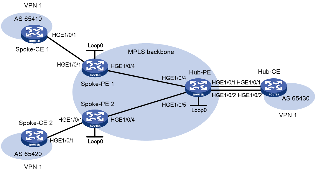
Table 3 Interface and IP address assignment
|
Device |
Interface |
IP address |
Device |
Interface |
IP address |
|
Spoke-CE 1 |
HGE1/0/1 |
10.1.1.1/24 |
Hub-CE |
HGE1/0/1 |
10.3.1.1/24 |
|
Spoke-PE 1 |
Loop0 |
1.1.1.9/32 |
|
HGE1/0/2 |
10.4.1.1/24 |
|
|
HGE1/0/1 |
10.1.1.2/24 |
Hub-PE |
Loop0 |
2.2.2.9/32 |
|
|
HGE1/0/4 |
172.1.1.1/24 |
|
HGE1/0/4 |
172.1.1.2/24 |
|
Spoke-CE 2 |
HGE1/0/1 |
10.2.1.1/24 |
|
HGE1/0/5 |
172.2.1.2/24 |
|
Spoke-PE 2 |
Loop0 |
3.3.3.9/32 |
|
HGE1/0/1 |
10.3.1.2/24 |
|
|
HGE1/0/1 |
10.2.1.2/24 |
|
HGE1/0/2 |
10.4.1.2/24 |
|
|
HGE1/0/4 |
172.2.1.1/24 |
|
|
|
Procedure
1. Configure an IGP on the MPLS backbone to ensure IP connectivity within the backbone:
# Configure Spoke-PE 1.
<Spoke-PE1> system-view
[Spoke-PE1] interface loopback 0
[Spoke-PE1-LoopBack0] ip address 1.1.1.9 32
[Spoke-PE1-LoopBack0] quit
[Spoke-PE1] interface hundredgige 1/0/4
[Spoke-PE1-HundredGigE1/0/4] ip address 172.1.1.1 24
[Spoke-PE1-HundredGigE1/0/4] quit
[Spoke-PE1] ospf
[Spoke-PE1-ospf-1] area 0
[Spoke-PE1-ospf-1-area-0.0.0.0] network 172.1.1.0 0.0.0.255
[Spoke-PE1-ospf-1-area-0.0.0.0] network 1.1.1.9 0.0.0.0
[Spoke-PE1-ospf-1-area-0.0.0.0] quit
[Spoke-PE1-ospf-1] quit
# Configure Spoke-PE 2.
<Spoke-PE2> system-view
[Spoke-PE2] interface loopback 0
[Spoke-PE2-LoopBack0] ip address 3.3.3.9 32
[Spoke-PE2-LoopBack0] quit
[Spoke-PE2] interface hundredgige 1/0/4
[Spoke-PE2-HundredGigE1/0/4] ip address 172.2.1.1 24
[Spoke-PE2-HundredGigE1/0/4] quit
[Spoke-PE2] ospf
[Spoke-PE2-ospf-1] area 0
[Spoke-PE2-ospf-1-area-0.0.0.0] network 172.2.1.0 0.0.0.255
[Spoke-PE2-ospf-1-area-0.0.0.0] network 3.3.3.9 0.0.0.0
[Spoke-PE2-ospf-1-area-0.0.0.0] quit
[Spoke-PE2-ospf-1] quit
# Configure Hub-PE.
<Hub-PE> system-view
[Hub-PE] interface loopback 0
[Hub-PE-LoopBack0] ip address 2.2.2.9 32
[Hub-PE-LoopBack0] quit
[Hub-PE] interface hundredgige 1/0/4
[Hub-PE-HundredGigE1/0/4] ip address 172.1.1.2 24
[Hub-PE-HundredGigE1/0/4] quit
[Hub-PE] interface hundredgige 1/0/5
[Hub-PE-HundredGigE1/0/5] ip address 172.2.1.2 24
[Hub-PE-HundredGigE1/0/5] quit
[Hub-PE] ospf
[Hub-PE-ospf-1] area 0
[Hub-PE-ospf-1-area-0.0.0.0] network 172.1.1.0 0.0.0.255
[Hub-PE-ospf-1-area-0.0.0.0] network 172.2.1.0 0.0.0.255
[Hub-PE-ospf-1-area-0.0.0.0] network 2.2.2.9 0.0.0.0
[Hub-PE-ospf-1-area-0.0.0.0] quit
[Hub-PE-ospf-1] quit
# Execute the display ospf peer command on the devices to verify that OSPF adjacencies in Full state have been established between Spoke-PE 1, Spoke-PE 2, and Hub-PE. Execute the display ip routing-table command on the devices to verify that the PEs have learned the routes to the loopback interfaces of each other. (Details not shown.)
2. Configure basic MPLS and MPLS LDP on the MPLS backbone to establish LDP LSPs:
# Configure Spoke-PE 1.
[Spoke-PE1] mpls lsr-id 1.1.1.9
[Spoke-PE1] mpls ldp
[Spoke-PE1-ldp] quit
[Spoke-PE1] interface hundredgige 1/0/4
[Spoke-PE1-HundredGigE1/0/4] mpls enable
[Spoke-PE1-HundredGigE1/0/4] mpls ldp enable
[Spoke-PE1-HundredGigE1/0/4] quit
# Configure Spoke-PE 2.
[Spoke-PE2] mpls lsr-id 3.3.3.9
[Spoke-PE2] mpls ldp
[Spoke-PE2-ldp] quit
[Spoke-PE2] interface hundredgige 1/0/4
[Spoke-PE2-HundredGigE1/0/4] mpls enable
[Spoke-PE2-HundredGigE1/0/4] mpls ldp enable
[Spoke-PE2-HundredGigE1/0/4] quit
# Configure Hub-PE.
[Hub-PE] mpls lsr-id 2.2.2.9
[Hub-PE] mpls ldp
[Hub-PE-ldp] quit
[Hub-PE] interface hundredgige 1/0/4
[Hub-PE-HundredGigE1/0/4] mpls enable
[Hub-PE-HundredGigE1/0/4] mpls ldp enable
[Hub-PE-HundredGigE1/0/4] quit
[Hub-PE] interface hundredgige 1/0/5
[Hub-PE-HundredGigE1/0/5] mpls enable
[Hub-PE-HundredGigE1/0/5] mpls ldp enable
[Hub-PE-HundredGigE1/0/5] quit
# Execute the display mpls ldp peer command on the devices to verify that LDP sessions in Operational state have been established between Spoke-PE 1, Spoke-PE 2, and Hub-PE. Execute the display mpls ldp lsp command on the devices to verify that the LSPs have been established by LDP. (Details not shown.)
3. Configure VPN instances on the Spoke-PEs and Hub-PE:
# Configure Spoke-PE 1.
[Spoke-PE1] ip vpn-instance vpn1
[Spoke-PE1-vpn-instance-vpn1] route-distinguisher 100:1
[Spoke-PE1-vpn-instance-vpn1] vpn-target 111:1 import-extcommunity
[Spoke-PE1-vpn-instance-vpn1] vpn-target 222:2 export-extcommunity
[Spoke-PE1-vpn-instance-vpn1] quit
[Spoke-PE1] interface hundredgige 1/0/1
[Spoke-PE1-HundredGigE1/0/1] ip binding vpn-instance vpn1
[Spoke-PE1-HundredGigE1/0/1] ip address 10.1.1.2 24
[Spoke-PE1-HundredGigE1/0/1] quit
# Configure Spoke-PE 2.
[Spoke-PE2] ip vpn-instance vpn1
[Spoke-PE2-vpn-instance-vpn1] route-distinguisher 100:2
[Spoke-PE2-vpn-instance-vpn1] vpn-target 111:1 import-extcommunity
[Spoke-PE2-vpn-instance-vpn1] vpn-target 222:2 export-extcommunity
[Spoke-PE2-vpn-instance-vpn1] quit
[Spoke-PE2] interface hundredgige 1/0/1
[Spoke-PE2-HundredGigE1/0/1] ip binding vpn-instance vpn1
[Spoke-PE2-HundredGigE1/0/1] ip address 10.2.1.2 24
[Spoke-PE2-HundredGigE1/0/1] quit
# Configure Hub-PE.
[Hub-PE] ip vpn-instance vpn1-in
[Hub-PE-vpn-instance-vpn1-in] route-distinguisher 100:3
[Hub-PE-vpn-instance-vpn1-in] vpn-target 222:2 import-extcommunity
[Hub-PE-vpn-instance-vpn1-in] quit
[Hub-PE] ip vpn-instance vpn1-out
[Hub-PE-vpn-instance-vpn1-out] route-distinguisher 100:4
[Hub-PE-vpn-instance-vpn1-out] vpn-target 111:1 export-extcommunity
[Hub-PE-vpn-instance-vpn1-out] quit
[Hub-PE] interface hundredgige 1/0/1
[Hub-PE-HundredGigE1/0/1] ip binding vpn-instance vpn1-in
[Hub-PE-HundredGigE1/0/1] ip address 10.3.1.2 24
[Hub-PE-HundredGigE1/0/1] quit
[Hub-PE] interface hundredgige 1/0/2
[Hub-PE-HundredGigE1/0/2] ip binding vpn-instance vpn1-out
[Hub-PE-HundredGigE1/0/2] ip address 10.4.1.2 24
[Hub-PE-HundredGigE1/0/2] quit
# Configure IP addresses for the CEs according to Table 3. (Details not shown.)
# Execute the display ip vpn-instance command on the PEs to display the configuration of the VPN instance.
# Use the ping command on the PEs to verify that the PEs can ping their attached CEs.
4. Establish EBGP peer relationships between the PEs and CEs, and redistribute VPN routes into BGP:
# Configure Spoke-CE 1.
<Spoke-CE1> system-view
[Spoke-CE1] bgp 65410
[Spoke-CE1-bgp-default] peer 10.1.1.2 as-number 100
[Spoke-CE1-bgp-default] address-family ipv4
[Spoke-CE1-bgp-default-ipv4] peer 10.1.1.2 enable
[Spoke-CE1-bgp-default-ipv4] import-route direct
[Spoke-CE1-bgp-default-ipv4] quit
[Spoke-CE1-bgp-default] quit
# Configure Spoke-CE 2.
<Spoke-CE2> system-view
[Spoke-CE2] bgp 65420
[Spoke-CE2-bgp-default] peer 10.2.1.2 as-number 100
[Spoke-CE2-bgp-default] address-family ipv4
[Spoke-CE2-bgp-default-ipv4] peer 10.2.1.2 enable
[Spoke-CE2-bgp-default-ipv4] import-route direct
[Spoke-CE2-bgp-default-ipv4] quit
[Spoke-CE2-bgp-default] quit
# Configure Hub-CE.
<Hub-CE> system-view
[Hub-CE] bgp 65430
[Hub-CE-bgp-default] peer 10.3.1.2 as-number 100
[Hub-CE-bgp-default] peer 10.4.1.2 as-number 100
[Hub-CE-bgp-default] address-family ipv4
[Hub-CE-bgp-default-ipv4] peer 10.3.1.2 enable
[Hub-CE-bgp-default-ipv4] peer 10.4.1.2 enable
[Hub-CE-bgp-default-ipv4] import-route direct
[Hub-CE-bgp-default-ipv4] quit
[Hub-CE-bgp-default] quit
# Configure Spoke-PE 1.
[Spoke-PE1] bgp 100
[Spoke-PE1-bgp-default] ip vpn-instance vpn1
[Spoke-PE1-bgp-default-vpn1] peer 10.1.1.1 as-number 65410
[Spoke-PE1-bgp-default-vpn1] address-family ipv4
[Spoke-PE1-bgp-default-ipv4-vpn1] peer 10.1.1.1 enable
[Spoke-PE1-bgp-default-ipv4-vpn1] quit
[Spoke-PE1-bgp-default-vpn1] quit
[Spoke-PE1-bgp-default] quit
# Configure Spoke-PE 2.
[Spoke-PE2] bgp 100
[Spoke-PE2-bgp-default] ip vpn-instance vpn1
[Spoke-PE2-bgp-default-vpn1] peer 10.2.1.1 as-number 65420
[Spoke-PE2-bgp-default-vpn1] address-family ipv4
[Spoke-PE2-bgp-default-ipv4-vpn1] peer 10.2.1.1 enable
[Spoke-PE2-bgp-default-ipv4-vpn1] quit
[Spoke-PE2-bgp-default-vpn1] quit
[Spoke-PE2-bgp-default] quit
# Configure Hub-PE.
[Hub-PE] bgp 100
[Hub-PE-bgp-default] ip vpn-instance vpn1-in
[Hub-PE-bgp-default-vpn1-in] peer 10.3.1.1 as-number 65430
[Hub-PE-bgp-default-vpn1-in] address-family ipv4
[Hub-PE-bgp-default-ipv4-vpn1-in] peer 10.3.1.1 enable
[Hub-PE-bgp-default-ipv4-vpn1-in] quit
[Hub-PE-bgp-default-vpn1-in] quit
[Hub-PE-bgp-default] ip vpn-instance vpn1-out
[Hub-PE-bgp-default-vpn1-out] peer 10.4.1.1 as-number 65430
[Hub-PE-bgp-default-vpn1-out] address-family ipv4
[Hub-PE-bgp-default-ipv4-vpn1-out] peer 10.4.1.1 enable
[Hub-PE-bgp-default-ipv4-vpn1-out] peer 10.4.1.1 allow-as-loop 2
[Hub-PE-bgp-default-ipv4-vpn1-out] quit
[Hub-PE-bgp-default-vpn1-out] quit
[Hub-PE-bgp-default] quit
# Execute the display bgp peer ipv4 vpn-instance command on the PEs to verify that a BGP peer relationship in Established state has been established between a PE and a CE. (Details not shown.)
5. Establish an MP-IBGP peer relationship between the Spoke-PEs and Hub-PE:
# Configure Spoke-PE 1.
[Spoke-PE1] bgp 100
[Spoke-PE1-bgp-default] peer 2.2.2.9 as-number 100
[Spoke-PE1-bgp-default] peer 2.2.2.9 connect-interface loopback 0
[Spoke-PE1-bgp-default] address-family vpnv4
[Spoke-PE1-bgp-default-vpnv4] peer 2.2.2.9 enable
[Spoke-PE1-bgp-default-vpnv4] quit
[Spoke-PE1-bgp-default] quit
# Configure Spoke-PE 2.
[Spoke-PE2] bgp 100
[Spoke-PE2-bgp-default] peer 2.2.2.9 as-number 100
[Spoke-PE2-bgp-default] peer 2.2.2.9 connect-interface loopback 0
[Spoke-PE2-bgp-default] address-family vpnv4
[Spoke-PE2-bgp-default-vpnv4] peer 2.2.2.9 enable
[Spoke-PE2-bgp-default-vpnv4] quit
[Spoke-PE2-bgp-default] quit
# Configure Hub-PE.
[Hub-PE] bgp 100
[Hub-PE-bgp-default] peer 1.1.1.9 as-number 100
[Hub-PE-bgp-default] peer 1.1.1.9 connect-interface loopback 0
[Hub-PE-bgp-default] peer 3.3.3.9 as-number 100
[Hub-PE-bgp-default] peer 3.3.3.9 connect-interface loopback 0
[Hub-PE-bgp-default] address-family vpnv4
[Hub-PE-bgp-default-vpnv4] peer 1.1.1.9 enable
[Hub-PE-bgp-default-vpnv4] peer 3.3.3.9 enable
[Hub-PE-bgp-default-vpnv4] quit
[Hub-PE-bgp-default] quit
# Execute the display bgp peer vpnv4 command on the PEs to verify that a BGP peer relationship in Established state has been established between the PEs. (Details not shown.)
Verifying the configuration
# Execute the display ip routing-table vpn-instance command on the PEs to display the routes to the CEs. This example uses Spoke-PE 1 to verify that the next hop of the route from a Spoke-PE to its connected Spoke-CE is Hub-PE.
[Spoke-PE1] display ip routing-table vpn-instance vpn1
Destinations : 15 Routes : 15
Destination/Mask Proto Pre Cost NextHop Interface
0.0.0.0/32 Direct 0 0 127.0.0.1 InLoop0
10.1.1.0/24 Direct 0 0 10.1.1.2 HGE1/0/1
10.1.1.0/32 Direct 0 0 10.1.1.2 HGE1/0/1
10.1.1.2/32 Direct 0 0 127.0.0.1 InLoop0
10.1.1.255/32 Direct 0 0 10.1.1.2 HGE1/0/1
10.2.1.0/24 BGP 255 0 2.2.2.9 HGE1/0/4
10.3.1.0/24 BGP 255 0 2.2.2.9 HGE1/0/4
10.4.1.0/24 BGP 255 0 2.2.2.9 HGE1/0/4
127.0.0.0/8 Direct 0 0 127.0.0.1 InLoop0
127.0.0.0/32 Direct 0 0 127.0.0.1 InLoop0
127.0.0.1/32 Direct 0 0 127.0.0.1 InLoop0
127.255.255.255/32 Direct 0 0 127.0.0.1 InLoop0
224.0.0.0/4 Direct 0 0 0.0.0.0 NULL0
224.0.0.0/24 Direct 0 0 0.0.0.0 NULL0
255.255.255.255/32 Direct 0 0 127.0.0.1 InLoop0
# Verify that Spoke-CE 1 and Spoke-CE 2 can ping each other. The TTL value indicates that traffic from Spoke-CE 1 to Spoke-CE 2 passes six hops (255-250+1) and is forwarded through Hub-CE. This example uses Spoke-CE 1 to verify their connectivity.
[Spoke-CE1] ping 10.2.1.1
Ping 10.2.1.1 (10.2.1.1): 56 data bytes, press CTRL_C to break
56 bytes from 10.2.1.1: icmp_seq=0 ttl=250 time=1.000 ms
56 bytes from 10.2.1.1: icmp_seq=1 ttl=250 time=2.000 ms
56 bytes from 10.2.1.1: icmp_seq=2 ttl=250 time=0.000 ms
56 bytes from 10.2.1.1: icmp_seq=3 ttl=250 time=1.000 ms
56 bytes from 10.2.1.1: icmp_seq=4 ttl=250 time=0.000 ms
--- Ping statistics for 10.2.1.1 ---
5 packet(s) transmitted, 5 packet(s) received, 0.0% packet loss
round-trip min/avg/max/std-dev = 0.000/0.800/2.000/0.748 ms
Example: Configuring MPLS L3VPN inter-AS option A
Network configuration
CE 1 and CE 2 belong to the same VPN. CE 1 accesses the network through PE 1 in AS 100, and CE 2 accesses the network through PE 2 in AS 200.
Configure inter-AS option A MPLS L3VPN, and use the VRF-to-VRF method to manage VPN routes.
Run OSPF on the MPLS backbone of each AS.
Figure 28 Network diagram
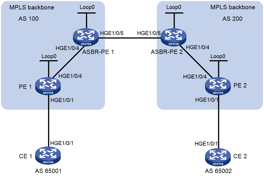
Table 4 Interface and IP address assignment
|
Interface |
IP address |
Device |
Interface |
IP address |
|
|
CE 1 |
HGE1/0/1 |
10.1.1.1/24 |
CE 2 |
HGE1/0/1 |
10.2.1.1/24 |
|
PE 1 |
Loop0 |
1.1.1.9/32 |
PE 2 |
Loop0 |
4.4.4.9/32 |
|
|
HGE1/0/1 |
10.1.1.2/24 |
|
HGE1/0/1 |
10.2.1.2/24 |
|
|
HGE1/0/4 |
172.1.1.2/24 |
|
HGE1/0/4 |
162.1.1.2/24 |
|
ASBR-PE1 |
Loop0 |
2.2.2.9/32 |
ASBR-PE2 |
Loop0 |
3.3.3.9/32 |
|
|
HGE1/0/4 |
172.1.1.1/24 |
|
HGE1/0/4 |
162.1.1.1/24 |
|
|
HGE1/0/5 |
192.1.1.1/24 |
|
HGE1/0/5 |
192.1.1.2/24 |
Restrictions and guidelines
For the same VPN, the route targets for the VPN instance on the PE must match those for the VPN instance on the ASBR-PE in the same AS. This is not required for PEs in different ASs.
Procedure
1. Configure IGP on the MPLS backbone.
This example uses OSPF. (Details not shown.)
# Execute the display ospf peer command to verify that each ASBR-PE has established an OSPF adjacency in Full state with the PE in the same AS, and that PEs and ASBR-PEs in the same AS have learned the routes to the loopback interfaces of each other. Verify that each ASBR-PE and the PE in the same AS can ping each other. (Details not shown.)
2. Configure basic MPLS and MPLS LDP on the MPLS backbone to establish LDP LSPs:
# Configure basic MPLS on PE 1, and enable MPLS LDP on the interface connected to ASBR-PE 1.
<PE1> system-view
[PE1] mpls lsr-id 1.1.1.9
[PE1] mpls ldp
[PE1-ldp] quit
[PE1] interface hundredgige 1/0/4
[PE1-HundredGigE1/0/4] mpls enable
[PE1-HundredGigE1/0/4] mpls ldp enable
[PE1-HundredGigE1/0/4] quit
# Configure basic MPLS on ASBR-PE 1, and enable MPLS LDP on the interface connected to PE 1.
<ASBR-PE1> system-view
[ASBR-PE1] mpls lsr-id 2.2.2.9
[ASBR-PE1] mpls ldp
[ASBR-PE1-ldp] quit
[ASBR-PE1] interface hundredgige 1/0/4
[ASBR-PE1-HundredGigE1/0/4] mpls enable
[ASBR-PE1-HundredGigE1/0/4] mpls ldp enable
[ASBR-PE1-HundredGigE1/0/4] quit
# Configure basic MPLS on ASBR-PE 2, and enable MPLS LDP on the interface connected to PE 2.
<ASBR-PE2> system-view
[ASBR-PE2] mpls lsr-id 3.3.3.9
[ASBR-PE2] mpls ldp
[ASBR-PE2-ldp] quit
[ASBR-PE2] interface hundredgige 1/0/4
[ASBR-PE2-HundredGigE1/0/4] mpls enable
[ASBR-PE2-HundredGigE1/0/4] mpls ldp enable
[ASBR-PE2-HundredGigE1/0/4] quit
# Configure basic MPLS on PE 2, and enable MPLS LDP on the interface connected to ASBR-PE 2.
<PE2> system-view
[PE2] mpls lsr-id 4.4.4.9
[PE2] mpls ldp
[PE2-ldp] quit
[PE2] interface hundredgige 1/0/4
[PE2-HundredGigE1/0/4] mpls enable
[PE2-HundredGigE1/0/4] mpls ldp enable
[PE2-HundredGigE1/0/4] quit
# Execute the display mpls ldp peer command on the devices to verify that the LDP session status is Operational, and that each PE and the ASBR-PE in the same AS have established an LDP neighbor relationship. (Details not shown.)
3. Configure VPN instances on PEs:
# Configure CE 1.
<CE1> system-view
[CE1] interface hundredgige 1/0/1
[CE1-HundredGigE1/0/1] ip address 10.1.1.1 24
[CE1-HundredGigE1/0/1] quit
# Configure PE 1.
[PE1] ip vpn-instance vpn1
[PE1-vpn-instance-vpn1] route-distinguisher 100:2
[PE1-vpn-instance-vpn1] vpn-target 100:1 both
[PE1-vpn-instance-vpn1] quit
[PE1] interface hundredgige 1/0/1
[PE1-HundredGigE1/0/1] ip binding vpn-instance vpn1
[PE1-HundredGigE1/0/1] ip address 10.1.1.2 24
[PE1-HundredGigE1/0/1] quit
# Configure CE 2.
<CE2> system-view
[CE2] interface hundredgige 1/0/1
[CE2-HundredGigE1/0/1] ip address 10.2.1.1 24
[CE2-HundredGigE1/0/1] quit
# Configure PE 2.
[PE2] ip vpn-instance vpn1
[PE2-vpn-instance-vpn1] route-distinguisher 200:2
[PE2-vpn-instance-vpn1] vpn-target 200:1 both
[PE2-vpn-instance-vpn1] quit
[PE2] interface hundredgige 1/0/1
[PE2-HundredGigE1/0/1] ip binding vpn-instance vpn1
[PE2-HundredGigE1/0/1] ip address 10.2.1.2 24
[PE2-HundredGigE1/0/1] quit
# On ASBR-PE 1, create a VPN instance, and bind the instance to the interface connected to ASBR-PE 2. ASBR-PE 1 considers ASBR-PE 2 to be its CE.
[ASBR-PE1] ip vpn-instance vpn1
[ASBR-PE1-vpn-instance-vpn1] route-distinguisher 100:1
[ASBR-PE1-vpn-instance-vpn1] vpn-target 100:1 both
[ASBR-PE1-vpn-instance-vpn1] quit
[ASBR-PE1] interface hundredgige 1/0/5
[ASBR-PE1-HundredGigE1/0/5] ip binding vpn-instance vpn1
[ASBR-PE1-HundredGigE1/0/5] ip address 192.1.1.1 24
[ASBR-PE1-HundredGigE1/0/5] quit
# On ASBR-PE 2, create a VPN instance, and bind the instance to the interface connected to ASBR-PE 1. ASBR-PE 2 considers ASBR-PE 1 to be its CE.
[ASBR-PE2] ip vpn-instance vpn1
[ASBR-PE2-vpn-instance-vpn1] route-distinguisher 200:1
[ASBR-PE2-vpn-instance-vpn1] vpn-target 200:1 both
[ASBR-PE2-vpn-instance-vpn1] quit
[ASBR-PE2] interface hundredgige 1/0/5
[ASBR-PE2-HundredGigE1/0/5] ip binding vpn-instance vpn1
[ASBR-PE2-HundredGigE1/0/5] ip address 192.1.1.2 24
[ASBR-PE2-HundredGigE1/0/5] quit
# Execute the display ip vpn-instance command to display VPN instance configurations. Verify that the PEs can ping their attached CEs, and the ASBR-PEs can ping each other. (Details not shown.)
4. Establish EBGP peer relationships between PEs and CEs, and redistribute VPN routes into BGP:
# Configure CE 1.
[CE1] bgp 65001
[CE1-bgp-default] peer 10.1.1.2 as-number 100
[CE1-bgp-default] address-family ipv4 unicast
[CE1-bgp-default-ipv4] peer 10.1.1.2 enable
[CE1-bgp-default-ipv4] import-route direct
[CE1-bgp-default-ipv4] quit
[CE1-bgp-default] quit
# Configure PE 1.
[PE1] bgp 100
[PE1-bgp-default] ip vpn-instance vpn1
[PE1-bgp-default-vpn1] peer 10.1.1.1 as-number 65001
[PE1-bgp-default-vpn1] address-family ipv4 unicast
[PE1-bgp-default-ipv4-vpn1] peer 10.1.1.1 enable
[PE1-bgp-default-ipv4-vpn1] quit
[PE1-bgp-default-vpn1] quit
[PE1-bgp-default] quit
# Configure CE 2.
[CE2] bgp 65002
[CE2-bgp-default] peer 10.2.1.2 as-number 200
[CE2-bgp-default] address-family ipv4 unicast
[CE2-bgp-default-ipv4] peer 10.2.1.2 enable
[CE2-bgp-default-ipv4] import-route direct
[CE2-bgp-default-ipv4] quit
[CE2-bgp-default] quit
# Configure PE 2.
[PE2] bgp 200
[PE2-bgp-default] ip vpn-instance vpn1
[PE2-bgp-default-vpn1] peer 10.2.1.1 as-number 65002
[PE2-bgp-default-vpn1] address-family ipv4 unicast
[PE2-bgp-default-ipv4-vpn1] peer 10.2.1.1 enable
[PE2-bgp-default-ipv4-vpn1] quit
[PE2-bgp-default-vpn1] quit
[PE2-bgp-default] quit
5. Establish an MP-IBGP peer relationship between each PE and the ASBR-PE in the same AS, and an EBGP peer relationship between the ASBR-PEs:
# Configure PE 1.
[PE1] bgp 100
[PE1-bgp-default] peer 2.2.2.9 as-number 100
[PE1-bgp-default] peer 2.2.2.9 connect-interface loopback 0
[PE1-bgp-default] address-family vpnv4
[PE1-bgp-default-vpnv4] peer 2.2.2.9 enable
[PE1-bgp-default-vpnv4] peer 2.2.2.9 next-hop-local
[PE1-bgp-default-vpnv4] quit
[PE1-bgp-default] quit
# Configure ASBR-PE 1.
[ASBR-PE1] bgp 100
[ASBR-PE1-bgp-default] ip vpn-instance vpn1
[ASBR-PE1-bgp-default-vpn1] peer 192.1.1.2 as-number 200
[ASBR-PE1-bgp-default-vpn1] address-family ipv4 unicast
[ASBR-PE1-bgp-default-ipv4-vpn1] peer 192.1.1.2 enable
[ASBR-PE1-bgp-default-ipv4-vpn1] quit
[ASBR-PE1-bgp-default-vpn1] quit
[ASBR-PE1-bgp-default] peer 1.1.1.9 as-number 100
[ASBR-PE1-bgp-default] peer 1.1.1.9 connect-interface loopback 0
[ASBR-PE1-bgp-default] address-family vpnv4
[ASBR-PE1-bgp-default-vpnv4] peer 1.1.1.9 enable
[ASBR-PE1-bgp-default-vpnv4] peer 1.1.1.9 next-hop-local
[ASBR-PE1-bgp-default-vpnv4] quit
[ASBR-PE1-bgp-default] quit
# Configure ASBR-PE 2.
[ASBR-PE2] bgp 200
[ASBR-PE2-bgp-default] ip vpn-instance vpn1
[ASBR-PE2-bgp-default-vpn1] peer 192.1.1.1 as-number 100
[ASBR-PE2-bgp-default-vpn1] address-family ipv4 unicast
[ASBR-PE2-bgp-default-ipv4-vpn1] peer 192.1.1.1 enable
[ASBR-PE2-bgp-default-ipv4-vpn1] quit
[ASBR-PE2-bgp-default-vpn1] quit
[ASBR-PE2-bgp-default] peer 4.4.4.9 as-number 200
[ASBR-PE2-bgp-default] peer 4.4.4.9 connect-interface loopback 0
[ASBR-PE2-bgp-default] address-family vpnv4
[ASBR-PE2-bgp-default-vpnv4] peer 4.4.4.9 enable
[ASBR-PE2-bgp-default-vpnv4] peer 4.4.4.9 next-hop-local
[ASBR-PE2-bgp-default-vpnv4] quit
[ASBR-PE2-bgp-default] quit
# Configure PE 2.
[PE2] bgp 200
[PE2-bgp-default] peer 3.3.3.9 as-number 200
[PE2-bgp-default] peer 3.3.3.9 connect-interface loopback 0
[PE2-bgp-default] address-family vpnv4
[PE2-bgp-default-vpnv4] peer 3.3.3.9 enable
[PE2-bgp-default-vpnv4] peer 3.3.3.9 next-hop-local
[PE2-bgp-default-vpnv4] quit
[PE2-bgp-default] quit
Verifying the configuration
# Verify that the CEs can learn the interface routes from each other and ping each other. (Details not shown.)
Example: Configuring MPLS L3VPN inter-AS option B
Network configuration
Site 1 and Site 2 belong to the same VPN. CE 1 of Site 1 accesses the network through PE 1 in AS 100, and CE 2 of Site 2 accesses the network through PE 2 in AS 600.
PEs in the same AS run IS-IS.
PE 1 and ASBR-PE 1 exchange VPNv4 routes through MP-IBGP. PE 2 and ASBR-PE 2 exchange VPNv4 routes through MP-IBGP. ASBR-PE 1 and ASBR-PE 2 exchange VPNv4 routes through MP-EBGP.
ASBRs do not perform route target filtering of received VPN-IPv4 routes.
Figure 29 Network diagram
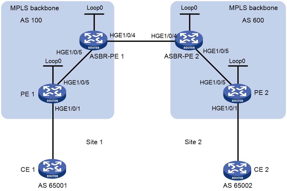
Table 5 Interface and IP address assignment
|
Interface |
IP address |
Device |
Interface |
IP address |
|
|
PE 1 |
Loop0 |
2.2.2.9/32 |
PE 2 |
Loop0 |
5.5.5.9/32 |
|
|
HGE1/0/1 |
30.0.0.1/8 |
|
HGE1/0/1 |
20.0.0.1/8 |
|
|
HGE1/0/5 |
1.1.1.2/8 |
|
HGE1/0/5 |
9.1.1.2/8 |
|
ASBR-PE 1 |
Loop0 |
3.3.3.9/32 |
ASBR-PE 2 |
Loop0 |
4.4.4.9/32 |
|
|
HGE1/0/5 |
1.1.1.1/8 |
|
HGE1/0/5 |
9.1.1.1/8 |
|
|
HGE1/0/4 |
11.0.0.2/8 |
|
HGE1/0/4 |
11.0.0.1/8 |
Procedure
1. Configure PE 1:
# Configure IS-IS on PE 1.
<PE1> system-view
[PE1] isis 1
[PE1-isis-1] network-entity 10.0000.0000.0000.0001.00
[PE1-isis-1] quit
# Configure LSR ID, and enable MPLS and LDP.
[PE1] mpls lsr-id 2.2.2.9
[PE1] mpls ldp
[PE1-ldp] quit
# Configure HundredGigE 1/0/5, and enable IS-IS, MPLS, and LDP on the interface.
[PE1] interface hundredgige 1/0/5
[PE1-HundredGigE1/0/5] ip address 1.1.1.2 255.0.0.0
[PE1-HundredGigE1/0/5] isis enable 1
[PE1-HundredGigE1/0/5] mpls enable
[PE1-HundredGigE1/0/5] mpls ldp enable
[PE1-HundredGigE1/0/5] quit
# Configure Loopback 0, and enable IS-IS on it.
[PE1] interface loopback 0
[PE1-LoopBack0] ip address 2.2.2.9 32
[PE1-LoopBack0] isis enable 1
[PE1-LoopBack0] quit
# Create VPN instance vpn1, and configure the RD and route target attributes.
[PE1] ip vpn-instance vpn1
[PE1-vpn-instance-vpn1] route-distinguisher 11:11
[PE1-vpn-instance-vpn1] vpn-target 1:1 2:2 import-extcommunity
[PE1-vpn-instance-vpn1] vpn-target 1:1 export-extcommunity
[PE1-vpn-instance-vpn1] quit
# Bind the interface connected to CE 1 to the created VPN instance.
[PE1] interface hundredgige 1/0/1
[PE1-HundredGigE1/0/1] ip binding vpn-instance vpn1
[PE1-HundredGigE1/0/1] ip address 30.0.0.1 8
[PE1-HundredGigE1/0/1] quit
# Enable BGP on PE 1.
[PE1] bgp 100
# Configure IBGP peer 3.3.3.9 as a VPNv4 peer.
[PE1-bgp-default] peer 3.3.3.9 as-number 100
[PE1-bgp-default] peer 3.3.3.9 connect-interface loopback 0
[PE1-bgp-default] address-family vpnv4
[PE1-bgp-default-vpnv4] peer 3.3.3.9 enable
[PE1-bgp-default-vpnv4] quit
# Redistribute direct routes to the VPN routing table of vpn1.
[PE1-bgp-default] ip vpn-instance vpn1
[PE1-bgp-default-vpn1] address-family ipv4 unicast
[PE1-bgp-default-ipv4-vpn1] import-route direct
[PE1-bgp-default-ipv4-vpn1] quit
[PE1-bgp-default-vpn1] quit
[PE1-bgp-default] quit
2. Configure ASBR-PE 1:
# Enable IS-IS on ASBR-PE 1.
<ASBR-PE1> system-view
[ASBR-PE1] isis 1
[ASBR-PE1-isis-1] network-entity 10.0000.0000.0000.0002.00
[ASBR-PE1-isis-1] quit
# Configure LSR ID, and enable MPLS and LDP.
[ASBR-PE1] mpls lsr-id 3.3.3.9
[ASBR-PE1] mpls ldp
[ASBR-PE1-ldp] quit
# Configure HundredGigE 1/0/5, and enable IS-IS, MPLS, and LDP on the interface.
[ASBR-PE1] interface hundredgige 1/0/5
[ASBR-PE1-HundredGigE1/0/5] ip address 1.1.1.1 255.0.0.0
[ASBR-PE1-HundredGigE1/0/5] isis enable 1
[ASBR-PE1-HundredGigE1/0/5] mpls enable
[ASBR-PE1-HundredGigE1/0/5] mpls ldp enable
[ASBR-PE1-HundredGigE1/0/5] quit
# Configure HundredGigE 1/0/4, and enable MPLS.
[ASBR-PE1] interface hundredgige 1/0/4
[ASBR-PE1-HundredGigE1/0/4] ip address 11.0.0.2 255.0.0.0
[ASBR-PE1-HundredGigE1/0/4] mpls enable
[ASBR-PE1-HundredGigE1/0/4] quit
# Configure Loopback 0, and enable IS-IS on it.
[ASBR-PE1] interface loopback 0
[ASBR-PE1-LoopBack0] ip address 3.3.3.9 32
[ASBR-PE1-LoopBack0] isis enable 1
[ASBR-PE1-LoopBack0] quit
# Enable BGP on ASBR-PE 1.
[ASBR-PE1] bgp 100
[ASBR-PE1-bgp-default] peer 2.2.2.9 as-number 100
[ASBR-PE1-bgp-default] peer 2.2.2.9 connect-interface loopback 0
[ASBR-PE1-bgp-default] peer 11.0.0.1 as-number 600
[ASBR-PE1-bgp-default] peer 11.0.0.1 connect-interface hundredgige 1/0/4
# Disable route target based filtering of received VPNv4 routes.
[ASBR-PE1-bgp-default] address-family vpnv4
[ASBR-PE1-bgp-default-vpnv4] undo policy vpn-target
# Configure both IBGP peer 2.2.2.9 and EBGP peer 11.0.0.1 as VPNv4 peers.
[ASBR-PE1-bgp-default-vpnv4] peer 11.0.0.1 enable
[ASBR-PE1-bgp-default-vpnv4] peer 2.2.2.9 enable
[ASBR-PE1-bgp-default-vpnv4] quit
3. Configure ASBR-PE 2:
# Enable IS-IS on ASBR-PE 2.
<ASBR-PE2> system-view
[ASBR-PE2] isis 1
[ASBR-PE2-isis-1] network-entity 10.0000.0000.0000.0003.00
[ASBR-PE2-isis-1] quit
# Configure LSR ID, and enable MPLS and LDP.
[ASBR-PE2] mpls lsr-id 4.4.4.9
[ASBR-PE2] mpls ldp
[ASBR-PE2-ldp] quit
# Configure HundredGigE 1/0/5, and enable IS-IS, MPLS, and LDP on the interface.
[ASBR-PE2] interface hundredgige 1/0/5
[ASBR-PE2-HundredGigE1/0/5] ip address 9.1.1.1 255.0.0.0
[ASBR-PE2-HundredGigE1/0/5] isis enable 1
[ASBR-PE2-HundredGigE1/0/5] mpls enable
[ASBR-PE2-HundredGigE1/0/5] mpls ldp enable
[ASBR-PE2-HundredGigE1/0/5] quit
# Configure HundredGigE 1/0/4, and enable MPLS.
[ASBR-PE2] interface hundredgige 1/0/4
[ASBR-PE2-HundredGigE1/0/4] ip address 11.0.0.1 255.0.0.0
[ASBR-PE2-HundredGigE1/0/4] mpls enable
[ASBR-PE2-HundredGigE1/0/4] quit
# Configure Loopback 0, and enable IS-IS on it.
[ASBR-PE2] interface loopback 0
[ASBR-PE2-LoopBack0] ip address 4.4.4.9 32
[ASBR-PE2-LoopBack0] isis enable 1
[ASBR-PE2-LoopBack0] quit
# Enable BGP on ASBR-PE 2.
[ASBR-PE2] bgp 600
[ASBR-PE2-bgp-default] peer 11.0.0.2 as-number 100
[ASBR-PE2-bgp-default] peer 11.0.0.2 connect-interface hundredgige 1/0/4
[ASBR-PE2-bgp-default] peer 5.5.5.9 as-number 600
[ASBR-PE2-bgp-default] peer 5.5.5.9 connect-interface loopback 0
# Disable route target based filtering of received VPNv4 routes.
[ASBR-PE2-bgp-default] address-family vpnv4
[ASBR-PE2-bgp-default-vpnv4] undo policy vpn-target
# Configure both IBGP peer 5.5.5.9 and EBGP peer 11.0.0.2 as VPNv4 peers.
[ASBR-PE2-bgp-default-vpnv4] peer 11.0.0.2 enable
[ASBR-PE2-bgp-default-vpnv4] peer 5.5.5.9 enable
[ASBR-PE2-bgp-default-vpnv4] quit
[ASBR-PE2-bgp-default] quit
4. Configure PE 2:
# Enable IS-IS on PE 2.
<PE2> system-view
[PE2] isis 1
[PE2-isis-1] network-entity 10.0000.0000.0000.0004.00
[PE2-isis-1] quit
# Configure the LSR ID, and enable MPLS and LDP.
[PE2] mpls lsr-id 5.5.5.9
[PE2] mpls ldp
[PE2-ldp] quit
# Configure HundredGigE 1/0/5, and enable IS-IS, MPLS, and LDP on the interface.
[PE2] interface hundredgige 1/0/5
[PE2-HundredGigE1/0/5] ip address 9.1.1.2 255.0.0.0
[PE2-HundredGigE1/0/5] isis enable 1
[PE2-HundredGigE1/0/5] mpls enable
[PE2-HundredGigE1/0/5] mpls ldp enable
[PE2-HundredGigE1/0/5] quit
# Configure Loopback 0, and enable IS-IS on it.
[PE2] interface loopback 0
[PE2-LoopBack0] ip address 5.5.5.9 32
[PE2-LoopBack0] isis enable 1
[PE2-LoopBack0] quit
# Create VPN instance vpn1, and configure the RD and route target attributes.
[PE2] ip vpn-instance vpn1
[PE2-vpn-instance-vpn1] route-distinguisher 12:12
[PE2-vpn-instance-vpn1] vpn-target 1:1 2:2 import-extcommunity
[PE2-vpn-instance-vpn1] vpn-target 2:2 export-extcommunity
[PE2-vpn-instance-vpn1] quit
# Bind the interface connected to CE 1 to the created VPN instance.
[PE2] interface hundredgige 1/0/1
[PE2-HundredGigE1/0/1] ip binding vpn-instance vpn1
[PE2-HundredGigE1/0/1] ip address 20.0.0.1 8
[PE2-HundredGigE1/0/1] quit
# Enable BGP on PE 2.
[PE2] bgp 600
# Configure IBGP peer 4.4.4.9 as a VPNv4 peer.
[PE2-bgp-default] peer 4.4.4.9 as-number 600
[PE2-bgp-default] peer 4.4.4.9 connect-interface loopback 0
[PE2-bgp-default] address-family vpnv4
[PE2-bgp-default-vpnv4] peer 4.4.4.9 enable
[PE2-bgp-default-vpnv4] quit
# Redistribute direct routes to the VPN routing table of vpn1.
[PE2-bgp-default] peer 4.4.4.9 as-number 600
[PE2-bgp-default] peer 4.4.4.9 connect-interface loopback 0
[PE2-bgp-default] address-family vpnv4
[PE2-bgp-default-vpnv4] peer 4.4.4.9 enable
[PE2-bgp-default-vpnv4] quit
Verifying the configuration
# Use the following command on PE 1 to verify its connectivity to PE 2.
[PE1] ping -a 30.0.0.1 -vpn-instance vpn1 20.0.0.1
Ping 20.0.0.1 (20.0.0.1) from 30.0.0.1: 56 data bytes, press CTRL_C to break
56 bytes from 20.0.0.1: icmp_seq=0 ttl=255 time=1.208 ms
56 bytes from 20.0.0.1: icmp_seq=1 ttl=255 time=0.867 ms
56 bytes from 20.0.0.1: icmp_seq=2 ttl=255 time=0.551 ms
56 bytes from 20.0.0.1: icmp_seq=3 ttl=255 time=0.566 ms
56 bytes from 20.0.0.1: icmp_seq=4 ttl=255 time=0.570 ms
--- Ping statistics for 20.0.0.1 ---
5 packet(s) transmitted, 5 packet(s) received, 0.0% packet loss
round-trip min/avg/max/std-dev = 0.551/0.752/1.208/0.257 ms
Example: Configuring MPLS L3VPN inter-AS option C (method 1)
Network configuration
Site 1 and Site 2 belong to the same VPN. Site 1 accesses the network through PE 1 in AS 100, and Site 2 accesses the network through PE 2 in AS 600. PEs in the same AS run IS-IS.
PE 1 and ASBR-PE 1 exchange labeled IPv4 routes through IBGP. PE 2 and ASBR-PE 2 exchange labeled IPv4 routes through IBGP. PE 1 and PE 2 are MP-EBGP peers and exchange VPNv4 routes.
ASBR-PE 1 and ASBR-PE 2 use routing policies and label the routes received from each other.
ASBR-PE 1 and ASBR-PE 2 use EBGP to exchange labeled IPv4 routes.
Figure 30 Network diagram

Table 6 Interface and IP address assignment
|
Interface |
IP address |
Device |
Interface |
IP address |
|
|
PE 1 |
Loop0 |
2.2.2.9/32 |
PE 2 |
Loop0 |
5.5.5.9/32 |
|
|
HGE1/0/1 |
30.0.0.1/24 |
|
HGE1/0/1 |
20.0.0.1/24 |
|
|
HGE1/0/5 |
1.1.1.2/8 |
|
HGE1/0/5 |
9.1.1.2/8 |
|
ASBR-PE 1 |
Loop0 |
3.3.3.9/32 |
ASBR-PE 2 |
Loop0 |
4.4.4.9/32 |
|
|
HGE1/0/5 |
1.1.1.1/8 |
|
HGE1/0/5 |
9.1.1.1/8 |
|
|
HGE1/0/4 |
11.0.0.2/8 |
|
HGE1/0/4 |
11.0.0.1/8 |
|
CE 1 |
HGE1/0/1 |
30.0.0.2/24 |
CE 2 |
HGE1/0/1 |
20.0.0.2/24 |
Procedure
1. Configure CE 1:
# Configure an IP address for HundredGigE 1/0/1.
<CE1> system-view
[CE1] interface hundredgige 1/0/1
[CE1-HundredGigE1/0/1] ip address 30.0.0.2 24
[CE1-HundredGigE1/0/1] quit
# Establish an EBGP peer relationship with PE 1, and redistribute VPN routes.
[CE1] bgp 65001
[CE1-bgp-default] peer 30.0.0.1 as-number 100
[CE1-bgp-default] address-family ipv4 unicast
[CE1-bgp-default-ipv4] peer 30.0.0.1 enable
[CE1-bgp-default-ipv4] import-route direct
[CE1-bgp-default-ipv4] quit
[CE1-bgp-default] quit
2. Configure PE 1:
# Configure IS-IS on PE 1.
<PE1> system-view
[PE1] isis 1
[PE1-isis-1] network-entity 10.0000.0000.0000.0001.00
[PE1-isis-1] quit
# Configure LSR ID, and enable MPLS and LDP.
[PE1] mpls lsr-id 2.2.2.9
[PE1] mpls ldp
[PE1-ldp] quit
# Configure HundredGigE 1/0/5, and enable IS-IS, MPLS, and LDP on the interface.
[PE1] interface hundredgige 1/0/5
[PE1-HundredGigE1/0/5] ip address 1.1.1.2 255.0.0.0
[PE1-HundredGigE1/0/5] isis enable 1
[PE1-HundredGigE1/0/5] mpls enable
[PE1-HundredGigE1/0/5] mpls ldp enable
[PE1-HundredGigE1/0/5] quit
# Configure Loopback 0, and start IS-IS on it.
[PE1] interface loopback 0
[PE1-LoopBack0] ip address 2.2.2.9 32
[PE1-LoopBack0] isis enable 1
[PE1-LoopBack0] quit
# Create VPN instance vpn1, and configure the RD and route target attributes.
[PE1] ip vpn-instance vpn1
[PE1-vpn-instance-vpn1] route-distinguisher 11:11
[PE1-vpn-instance-vpn1] vpn-target 1:1 2:2 3:3 import-extcommunity
[PE1-vpn-instance-vpn1] vpn-target 3:3 export-extcommunity
[PE1-vpn-instance-vpn1] quit
# Associate interface HundredGigE 1/0/1 with VPN instance vpn1, and specify the IP address for the interface.
[PE1] interface hundredgige 1/0/1
[PE1-HundredGigE1/0/1] ip binding vpn-instance vpn1
[PE1-HundredGigE1/0/1] ip address 30.0.0.1 24
[PE1-HundredGigE1/0/1] quit
# Start BGP on PE 1.
[PE1] bgp 100
# Enable the capability to advertise labeled routes to IBGP peer 3.3.3.9 and to receive labeled routes from the peer.
[PE1-bgp-default] peer 3.3.3.9 as-number 100
[PE1-bgp-default] peer 3.3.3.9 connect-interface loopback 0
[PE1-bgp-default] address-family ipv4 unicast
[PE1-bgp-default-ipv4] peer 3.3.3.9 enable
[PE1-bgp-default-ipv4] peer 3.3.3.9 label-route-capability
[PE1-bgp-default-ipv4] quit
# Configure the maximum hop count from PE 1 to EBGP peer 5.5.5.9 as 10.
[PE1-bgp-default] peer 5.5.5.9 as-number 600
[PE1-bgp-default] peer 5.5.5.9 connect-interface loopback 0
[PE1-bgp-default] peer 5.5.5.9 ebgp-max-hop 10
# Configure peer 5.5.5.9 as a VPNv4 peer.
[PE1-bgp-default] address-family vpnv4
[PE1-bgp-default-vpnv4] peer 5.5.5.9 enable
[PE1-bgp-default-vpnv4] quit
# Establish an EBGP peer relationship with CE 1, and add the learned BGP routes to the routing table of VPN instance vpn1.
[PE1-bgp-default] ip vpn-instance vpn1
[PE1-bgp-default-vpn1] peer 30.0.0.2 as-number 65001
[PE1-bgp-default-vpn1] address-family ipv4 unicast
[PE1-bgp-default-ipv4-vpn1] peer 30.0.0.2 enable
[PE1-bgp-default-ipv4-vpn1] quit
[PE1-bgp-default-vpn1] quit
[PE1-bgp-default] quit
3. Configure ASBR-PE 1:
# Start IS-IS on ASBR-PE 1.
<ASBR-PE1> system-view
[ASBR-PE1] isis 1
[ASBR-PE1-isis-1] network-entity 10.0000.0000.0000.0002.00
[ASBR-PE1-isis-1] quit
# Configure the LSR ID, and enable MPLS and LDP.
[ASBR-PE1] mpls lsr-id 3.3.3.9
[ASBR-PE1] mpls ldp
[ASBR-PE1-ldp] quit
# Configure HundredGigE 1/0/5, and enable IS-IS, MPLS, and LDP on the interface.
[ASBR-PE1] interface hundredgige 1/0/5
[ASBR-PE1-HundredGigE1/0/5] ip address 1.1.1.1 255.0.0.0
[ASBR-PE1-HundredGigE1/0/5] isis enable 1
[ASBR-PE1-HundredGigE1/0/5] mpls enable
[ASBR-PE1-HundredGigE1/0/5] mpls ldp enable
[ASBR-PE1-HundredGigE1/0/5] quit
# Configure HundredGigE 1/0/4, and enable MPLS on it.
[ASBR-PE1] interface hundredgige 1/0/4
[ASBR-PE1-HundredGigE1/0/4] ip address 11.0.0.2 255.0.0.0
[ASBR-PE1-HundredGigE1/0/4] mpls enable
[ASBR-PE1-HundredGigE1/0/4] quit
# Configure Loopback 0, and start IS-IS on it.
[ASBR-PE1] interface loopback 0
[ASBR-PE1-LoopBack0] ip address 3.3.3.9 32
[ASBR-PE1-LoopBack0] isis enable 1
[ASBR-PE1-LoopBack0] quit
# Create routing policies.
[ASBR-PE1] route-policy policy1 permit node 1
[ASBR-PE1-route-policy-policy1-1] apply mpls-label
[ASBR-PE1-route-policy-policy1-1] quit
[ASBR-PE1] route-policy policy2 permit node 1
[ASBR-PE1-route-policy-policy2-1] if-match mpls-label
[ASBR-PE1-route-policy-policy2-1] apply mpls-label
[ASBR-PE1-route-policy-policy2-1] quit
# Start BGP on ASBR-PE 1, and apply the routing policy policy2 to routes advertised to IBGP peer 2.2.2.9.
[ASBR-PE1] bgp 100
[ASBR-PE1-bgp-default] peer 2.2.2.9 as-number 100
[ASBR-PE1-bgp-default] peer 2.2.2.9 connect-interface loopback 0
[ASBR-PE1-bgp-default] address-family ipv4 unicast
[ASBR-PE1-bgp-default-ipv4] peer 2.2.2.9 enable
[ASBR-PE1-bgp-default-ipv4] peer 2.2.2.9 route-policy policy2 export
# Enable the capability to advertise labeled routes to IBGP peer 2.2.2.9 and to receive labeled routes from the peer.
[ASBR-PE1-bgp-default-ipv4] peer 2.2.2.9 label-route-capability
# Redistribute routes from IS-IS process 1 to BGP.
[ASBR-PE1-bgp-default-ipv4] import-route isis 1
[ASBR-PE1-bgp-default-ipv4] quit
# Apply routing policy policy1 to routes advertised to EBGP peer 11.0.0.1.
[ASBR-PE1-bgp-default] peer 11.0.0.1 as-number 600
[ASBR-PE1-bgp-default] address-family ipv4 unicast
[ASBR-PE1-bgp-default-ipv4] peer 11.0.0.1 enable
[ASBR-PE1-bgp-default-ipv4] peer 11.0.0.1 route-policy policy1 export
# Enable the capability to advertise labeled routes to EBGP peer 11.0.0.1 and to receive labeled routes from the peer.
[ASBR-PE1-bgp-default-ipv4] peer 11.0.0.1 label-route-capability
[ASBR-PE1-bgp-default-ipv4] quit
[ASBR-PE1-bgp-default] quit
4. Configure ASBR-PE 2:
# Enable IS-IS on ASBR-PE 2.
<ASBR-PE2> system-view
[ASBR-PE2] isis 1
[ASBR-PE2-isis-1] network-entity 10.0000.0000.0000.0003.00
[ASBR-PE2-isis-1] quit
# Configure the LSR ID, and enable MPLS and LDP.
[ASBR-PE2] mpls lsr-id 4.4.4.9
[ASBR-PE2] mpls ldp
[ASBR-PE2-ldp] quit
# Configure HundredGigE 1/0/5, and enable IS-IS, MPLS, and LDP on the interface.
[ASBR-PE2] interface hundredgige 1/0/5
[ASBR-PE2-HundredGigE1/0/5] ip address 9.1.1.1 255.0.0.0
[ASBR-PE2-HundredGigE1/0/5] isis enable 1
[ASBR-PE2-HundredGigE1/0/5] mpls enable
[ASBR-PE2-HundredGigE1/0/5] mpls ldp enable
[ASBR-PE2-HundredGigE1/0/5] quit
# Configure Loopback 0, and enable IS-IS on it.
[ASBR-PE2] interface loopback 0
[ASBR-PE2-LoopBack0] ip address 4.4.4.9 32
[ASBR-PE2-LoopBack0] isis enable 1
[ASBR-PE2-LoopBack0] quit
# Configure HundredGigE 1/0/4, and enable MPLS on the interface.
[ASBR-PE2] interface hundredgige 1/0/4
[ASBR-PE2-HundredGigE1/0/4] ip address 11.0.0.1 255.0.0.0
[ASBR-PE2-HundredGigE1/0/4] mpls enable
[ASBR-PE2-HundredGigE1/0/4] quit
# Create routing policies.
[ASBR-PE2] route-policy policy1 permit node 1
[ASBR-PE2-route-policy-policy1-1] apply mpls-label
[ASBR-PE2-route-policy-policy1-1] quit
[ASBR-PE2] route-policy policy2 permit node 1
[ASBR-PE2-route-policy-policy2-1] if-match mpls-label
[ASBR-PE2-route-policy-policy2-1] apply mpls-label
[ASBR-PE2-route-policy-policy2-1] quit
# Enable BGP on ASBR-PE 2, and enable the capability to advertise labeled routes to IBGP peer 5.5.5.9 and to receive labeled routes from the peer.
[ASBR-PE2] bgp 600
[ASBR-PE2-bgp-default] peer 5.5.5.9 as-number 600
[ASBR-PE2-bgp-default] peer 5.5.5.9 connect-interface loopback 0
[ASBR-PE2-bgp-default] address-family ipv4 unicast
[ASBR-PE2-bgp-default-ipv4] peer 5.5.5.9 enable
[ASBR-PE2-bgp-default-ipv4] peer 5.5.5.9 label-route-capability
# Apply routing policy policy2 to routes advertised to IBGP peer 5.5.5.9.
[ASBR-PE2-bgp-default-ipv4] peer 5.5.5.9 route-policy policy2 export
# Redistribute routes from IS-IS process 1.
[ASBR-PE2-bgp-default-ipv4] import-route isis 1
[ASBR-PE2-bgp-default-ipv4] quit
# Apply routing policy policy1 to routes advertised to EBGP peer 11.0.0.2.
[ASBR-PE2-bgp-default] peer 11.0.0.2 as-number 100
[ASBR-PE2-bgp-default] address-family ipv4 unicast
[ASBR-PE2-bgp-default-ipv4] peer 11.0.0.2 enable
[ASBR-PE2-bgp-default-ipv4] peer 11.0.0.2 route-policy policy1 export
# Enable the capability to advertise labeled routes to EBGP peer 11.0.0.2 and to receive labeled routes from the peer.
[ASBR-PE2-bgp-default-ipv4] peer 11.0.0.2 label-route-capability
[ASBR-PE2-bgp-default-ipv4] quit
[ASBR-PE2-bgp-default] quit
5. Configure PE 2:
# Enable IS-IS on PE 2.
<PE2> system-view
[PE2] isis 1
[PE2-isis-1] network-entity 10.0000.0000.0000.0004.00
[PE2-isis-1] quit
# Configure the LSR ID, and enable MPLS and LDP.
[PE2] mpls lsr-id 5.5.5.9
[PE2] mpls ldp
[PE2-ldp] quit
# Configure HundredGigE 1/0/5, and enable IS-IS, MPLS, and LDP on the interface.
[PE2] interface hundredgige 1/0/5
[PE2-HundredGigE1/0/5] ip address 9.1.1.2 255.0.0.0
[PE2-HundredGigE1/0/5] isis enable 1
[PE2-HundredGigE1/0/5] mpls enable
[PE2-HundredGigE1/0/5] mpls ldp enable
[PE2-HundredGigE1/0/5] quit
# Configure Loopback 0, and enable IS-IS on it.
[PE2] interface loopback 0
[PE2-LoopBack0] ip address 5.5.5.9 32
[PE2-LoopBack0] isis enable 1
[PE2-LoopBack0] quit
# Create VPN instance vpn1, and configure the RD and route target attributes.
[PE2] ip vpn-instance vpn1
[PE2-vpn-instance-vpn1] route-distinguisher 11:11
[PE2-vpn-instance-vpn1] vpn-target 1:1 2:2 3:3 import-extcommunity
[PE2-vpn-instance-vpn1] vpn-target 3:3 export-extcommunity
[PE2-vpn-instance-vpn1] quit
# Associate HundredGigE 1/0/1 with VPN instance vpn1, and specify the IP address for the interface.
[PE2] interface hundredgige 1/0/1
[PE2-HundredGigE1/0/1] ip binding vpn-instance vpn1
[PE2-HundredGigE1/0/1] ip address 20.0.0.1 24
[PE2-HundredGigE1/0/1] quit
# Enable BGP on PE 2.
[PE2] bgp 600
# Enable the capability to advertise labeled routes to IBGP peer 4.4.4.9 and to receive labeled routes from the peer.
[PE2-bgp-default] peer 4.4.4.9 as-number 600
[PE2-bgp-default] peer 4.4.4.9 connect-interface loopback 0
[PE2-bgp-default] address-family ipv4 unicast
[PE2-bgp-default-ipv4] peer 4.4.4.9 enable
[PE2-bgp-default-ipv4] peer 4.4.4.9 label-route-capability
[PE2-bgp-default-ipv4] quit
# Configure the maximum hop count from PE 2 to EBGP peer 2.2.2.9 as 10.
[PE2-bgp-default] peer 2.2.2.9 as-number 100
[PE2-bgp-default] peer 2.2.2.9 connect-interface loopback 0
[PE2-bgp-default] peer 2.2.2.9 ebgp-max-hop 10
# Configure peer 2.2.2.9 as a VPNv4 peer.
[PE2-bgp-default] address-family vpnv4
[PE2-bgp-default-vpnv4] peer 2.2.2.9 enable
[PE2-bgp-default-vpnv4] quit
# Establish an EBGP peer relationship with CE 2, and add the learned BGP routes to the routing table of VPN instance vpn1.
[PE2-bgp-default] ip vpn-instance vpn1
[PE2-bgp-default-vpn1] peer 20.0.0.2 as-number 65002
[PE2-bgp-default-vpn1] address-family ipv4 unicast
[PE2-bgp-default-ipv4-vpn1] peer 20.0.0.2 enable
[PE2-bgp-default-ipv4-vpn1] quit
[PE2-bgp-default-vpn1] quit
[PE2-bgp-default] quit
6. Configure CE 2:
# Configure an IP address for HundredGigE 1/0/1.
<CE2> system-view
[CE2] interface hundredgige 1/0/1
[CE2-HundredGigE1/0/1] ip address 20.0.0.2 24
[CE2-HundredGigE1/0/1] quit
# Establish an EBGP peer relationship with PE 2, and redistribute VPN routes.
[CE2] bgp 65002
[CE2-bgp-default] peer 20.0.0.1 as-number 600
[CE2-bgp-default] address-family ipv4 unicast
[CE2-bgp-default-ipv4] peer 20.0.0.1 enable
[CE2-bgp-default-ipv4] import-route direct
[CE2-bgp-default-ipv4] quit
[CE2-bgp-default] quit
Verifying the configuration
# Execute the display ip routing table command on CE 1 and CE 2 to verify that CE 1 and CE 2 have a route to each other. Verify that CE 1 and CE 2 can ping each other. (Details not shown.)
Example: Configuring MPLS L3VPN inter-AS option C (method 2)
Network configuration
Site 1 and Site 2 belong to the same VPN. Site 1 accesses the network through PE 1 in AS 100, and Site 2 accesses the network through PE 2 in AS 600. PEs in the same AS run IS-IS.
PE 1 and PE 2 are MP-EBGP peers and exchange VPNv4 routes.
ASBR-PE 1 and ASBR-PE 2 label the routes received from each other, use EBGP to exchange labeled IPv4 routes, and redistribute IGP and BGP routes from each other.
Figure 31 Network diagram
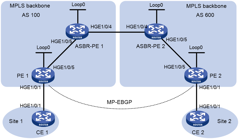
Table 7 Interface and IP address assignment
|
Device |
Interface |
IP address |
Device |
Interface |
IP address |
|
PE 1 |
Loop0 |
2.2.2.9/32 |
PE 2 |
Loop0 |
5.5.5.9/32 |
|
|
HGE1/0/1 |
30.0.0.1/24 |
|
HGE1/0/1 |
20.0.0.1/24 |
|
|
HGE1/0/5 |
1.1.1.2/8 |
|
HGE1/0/5 |
9.1.1.2/8 |
|
ASBR-PE 1 |
Loop0 |
3.3.3.9/32 |
ASBR-PE 2 |
Loop0 |
4.4.4.9/32 |
|
|
HGE1/0/5 |
1.1.1.1/8 |
|
HGE1/0/5 |
9.1.1.1/8 |
|
|
HGE1/0/4 |
11.0.0.2/8 |
|
HGE1/0/4 |
11.0.0.1/8 |
|
CE 1 |
HGE1/0/1 |
30.0.0.2/24 |
CE 2 |
HGE1/0/1 |
20.0.0.2/24 |
Procedure
1. Configure CE 1:
# Configure an IP address for HundredGigE 1/0/1.
<CE1> system-view
[CE1] interface hundredgige 1/0/1
[CE1-HundredGigE1/0/1] ip address 30.0.0.2 24
[CE1-HundredGigE1/0/1] quit
# Establish an EBGP peer relationship with PE 1, and redistribute VPN routes.
[CE1] bgp 65001
[CE1-bgp-default] peer 30.0.0.1 as-number 100
[CE1-bgp-default] address-family ipv4 unicast
[CE1-bgp-default-ipv4] peer 30.0.0.1 enable
[CE1-bgp-default-ipv4] import-route direct
[CE1-bgp-default-ipv4] quit
[CE1-bgp-default] quit
2. Configure PE 1:
# Configure IS-IS on PE 1.
<PE1> system-view
[PE1] isis 1
[PE1-isis-1] network-entity 10.0000.0000.0000.0001.00
[PE1-isis-1] quit
# Configure an LSR ID, and enable MPLS and LDP.
[PE1] mpls lsr-id 2.2.2.9
[PE1] mpls ldp
[PE1-ldp] quit
# Enable IS-IS, MPLS, and LDP on interface HundredGigE 1/0/5.
[PE1] interface hundredgige 1/0/5
[PE1-HundredGigE1/0/5] ip address 1.1.1.2 255.0.0.0
[PE1-HundredGigE1/0/5] isis enable 1
[PE1-HundredGigE1/0/5] mpls enable
[PE1-HundredGigE1/0/5] mpls ldp enable
[PE1-HundredGigE1/0/5] quit
# Enable IS-IS on interface Loopback 0.
[PE1] interface loopback 0
[PE1-LoopBack0] ip address 2.2.2.9 32
[PE1-LoopBack0] isis enable 1
[PE1-LoopBack0] quit
# Create VPN instance vpn1, and configure the RD and route target attributes.
[PE1] ip vpn-instance vpn1
[PE1-vpn-instance-vpn1] route-distinguisher 11:11
[PE1-vpn-instance-vpn1] vpn-target 1:1 2:2 3:3 import-extcommunity
[PE1-vpn-instance-vpn1] vpn-target 3:3 export-extcommunity
[PE1-vpn-instance-vpn1] quit
# Associate interface HundredGigE 1/0/5 with VPN instance vpn1, and specify an IP address for the interface.
[PE1] interface hundredgige 1/0/1
[PE1-HundredGigE1/0/1] ip binding vpn-instance vpn1
[PE1-HundredGigE1/0/1] ip address 30.0.0.1 24
[PE1-HundredGigE1/0/1] quit
# Enable BGP on PE 1.
[PE1] bgp 100
# Configure the maximum hop count from PE 1 to EBGP peer 5.5.5.9 as 10.
[PE1-bgp-default] peer 5.5.5.9 as-number 600
[PE1-bgp-default] peer 5.5.5.9 connect-interface loopback 0
[PE1-bgp-default] peer 5.5.5.9 ebgp-max-hop 10
# Configure peer 5.5.5.9 as a VPNv4 peer.
[PE1-bgp-default] address-family vpnv4
[PE1-bgp-default-vpnv4] peer 5.5.5.9 enable
[PE1-bgp-default-vpnv4] quit
# Establish an EBGP peer relationship with CE 1, and add the learned BGP routes to the routing table of VPN instance vpn1.
[PE1-bgp-default] ip vpn-instance vpn1
[PE1-bgp-default-vpn1] peer 30.0.0.2 as-number 65001
[PE1-bgp-default-vpn1] address-family ipv4 unicast
[PE1-bgp-default-ipv4-vpn1] peer 30.0.0.2 enable
[PE1-bgp-default-ipv4-vpn1] quit
[PE1-bgp-default-vpn1] quit
[PE1-bgp-default] quit
3. Configure ASBR-PE1:
# Enable IS-IS on ASBR-PE 1.
<ASBR-PE1> system-view
[ASBR-PE1] isis 1
[ASBR-PE1-isis-1] network-entity 10.0000.0000.0000.0002.00
# Redistribute BGP routes.
[ASBR-PE1-isis-1] address-family ipv4 unicast
[ASBR-PE1-isis-1-ipv4] import-route bgp
[ASBR-PE1-isis-1-ipv4] quit
[ASBR-PE1-isis-1] quit
# Configure an LSR ID, and enable MPLS and LDP.
[ASBR-PE1] mpls lsr-id 3.3.3.9
[ASBR-PE1] mpls ldp
[ASBR-PE1-ldp] quit
# Configure interface HundredGigE 1/0/5, and enable IS-IS, MPLS, and LDP on the interface.
[ASBR-PE1] interface hundredgige 1/0/5
[ASBR-PE1-HundredGigE1/0/5] ip address 1.1.1.1 255.0.0.0
[ASBR-PE1-HundredGigE1/0/5] isis enable 1
[ASBR-PE1-HundredGigE1/0/5] mpls enable
[ASBR-PE1-HundredGigE1/0/5] mpls ldp enable
[ASBR-PE1-HundredGigE1/0/5] quit
# Configure HundredGigE 1/0/4, and enable MPLS on it.
[ASBR-PE1] interface hundredgige 1/0/4
[ASBR-PE1-HundredGigE1/0/4] ip address 11.0.0.2 255.0.0.0
[ASBR-PE1-HundredGigE1/0/4] mpls enable
[ASBR-PE1-HundredGigE1/0/4] quit
# Configure interface Loopback 0, and enable IS-IS on it.
[ASBR-PE1] interface loopback 0
[ASBR-PE1-LoopBack0] ip address 3.3.3.9 32
[ASBR-PE1-LoopBack0] isis enable 1
[ASBR-PE1-LoopBack0] quit
# Create routing policy policy1.
[ASBR-PE1] route-policy policy1 permit node 1
[ASBR-PE1-route-policy-policy1-1] apply mpls-label
[ASBR-PE1-route-policy-policy1-1] quit
# Enable BGP on ASBR-PE 1, and redistribute routes from IS-IS process 1.
[ASBR-PE1] bgp 100
[ASBR-PE1-bgp-default] address-family ipv4 unicast
[ASBR-PE1-bgp-default-ipv4] import-route isis 1
[ASBR-PE1-bgp-default-ipv4] quit
# Apply routing policy policy1 to routes advertised to EBGP peer 11.0.0.1.
[ASBR-PE1-bgp-default] peer 11.0.0.1 as-number 600
[ASBR-PE1-bgp-default] address-family ipv4 unicast
[ASBR-PE1-bgp-default-ipv4] peer 11.0.0.1 enable
[ASBR-PE1-bgp-default-ipv4] peer 11.0.0.1 route-policy policy1 export
# Enable the capability to advertise labeled routes to EBGP peer 11.0.0.1 and to receive labeled routes from the peer.
[ASBR-PE1-bgp-default-ipv4] peer 11.0.0.1 label-route-capability
[ASBR-PE1-bgp-default-ipv4] quit
[ASBR-PE1-bgp-default] quit
4. Configure ASBR-PE 2:
# Enable IS-IS on ASBR-PE 2.
<ASBR-PE2> system-view
[ASBR-PE2] isis 1
[ASBR-PE2-isis-1] network-entity 10.0000.0000.0000.0003.00
# Redistribute BGP routes.
[ASBR-PE2-isis-1] address-family ipv4 unicast
[ASBR-PE2-isis-1-ipv4] import-route bgp
[ASBR-PE2-isis-1-ipv4] quit
[ASBR-PE2-isis-1] quit
# Configure an LSR ID, and enable MPLS and LDP.
[ASBR-PE2] mpls lsr-id 4.4.4.9
[ASBR-PE2] mpls ldp
[ASBR-PE2-ldp] quit
# Configure HundredGigE 1/0/5, and enable IS-IS, MPLS, and LDP on the interface.
[ASBR-PE2] interface hundredgige 1/0/5
[ASBR-PE2-HundredGigE1/0/5] ip address 9.1.1.1 255.0.0.0
[ASBR-PE2-HundredGigE1/0/5] isis enable 1
[ASBR-PE2-HundredGigE1/0/5] mpls enable
[ASBR-PE2-HundredGigE1/0/5] mpls ldp enable
[ASBR-PE2-HundredGigE1/0/5] quit
# Configure Loopback 0, and enable IS-IS on it.
[ASBR-PE2] interface loopback 0
[ASBR-PE2-LoopBack0] ip address 4.4.4.9 32
[ASBR-PE2-LoopBack0] isis enable 1
[ASBR-PE2-LoopBack0] quit
# Configure HundredGigE 1/0/4, and enable MPLS on the interface.
[ASBR-PE2] interface hundredgige 1/0/4
[ASBR-PE2-HundredGigE1/0/4] ip address 11.0.0.1 255.0.0.0
[ASBR-PE2-HundredGigE1/0/4] mpls enable
[ASBR-PE2-HundredGigE1/0/4] quit
# Create routing policy policy1.
[ASBR-PE2] route-policy policy1 permit node 1
[ASBR-PE2-route-policy-policy1-1] apply mpls-label
[ASBR-PE2-route-policy-policy1-1] quit
# Enable BGP on ASBR-PE 2, and redistribute routes from IS-IS process 1.
[ASBR-PE2] bgp 600
[ASBR-PE2-bgp-default] address-family ipv4 unicast
[ASBR-PE2-bgp-default-ipv4] import-route isis 1
[ASBR-PE2-bgp-default-ipv4] quit
# Apply routing policy policy1 to routes advertised to EBGP peer 11.0.0.2.
[ASBR-PE2-bgp-default] peer 11.0.0.2 as-number 100
[ASBR-PE2-bgp-default] address-family ipv4 unicast
[ASBR-PE2-bgp-default-ipv4] peer 11.0.0.2 enable
[ASBR-PE2-bgp-default-ipv4] peer 11.0.0.2 route-policy policy1 export
# Enable the capability to advertise labeled routes to EBGP peer 11.0.0.2 and to receive labeled routes from the peer.
[ASBR-PE2-bgp-default-ipv4] peer 11.0.0.2 label-route-capability
[ASBR-PE2-bgp-default-ipv4] quit
[ASBR-PE2-bgp-default] quit
5. Configure PE 2:
# Enable IS-IS on PE 2.
<PE2> system-view
[PE2] isis 1
[PE2-isis-1] network-entity 10.0000.0000.0000.0004.00
[PE2-isis-1] quit
# Configure an LSR ID, and enable MPLS and LDP.
[PE2] mpls lsr-id 5.5.5.9
[PE2] mpls ldp
[PE2-ldp] quit
# Configure interface HundredGigE 1/0/5, and enable IS-IS, MPLS, and LDP on the interface.
[PE2] interface hundredgige 1/0/5
[PE2-HundredGigE1/0/5] ip address 9.1.1.2 255.0.0.0
[PE2-HundredGigE1/0/5] isis enable 1
[PE2-HundredGigE1/0/5] mpls enable
[PE2-HundredGigE1/0/5] mpls ldp enable
[PE2-HundredGigE1/0/5] quit
# Configure interface Loopback 0, and enable IS-IS on it.
[PE2] interface loopback 0
[PE2-LoopBack0] ip address 5.5.5.9 32
[PE2-LoopBack0] isis enable 1
[PE2-LoopBack0] quit
# Create VPN instance vpn1, and configure the RD and route target attributes.
[PE2] ip vpn-instance vpn1
[PE2-vpn-instance-vpn1] route-distinguisher 11:11
[PE2-vpn-instance-vpn1] vpn-target 1:1 2:2 3:3 import-extcommunity
[PE2-vpn-instance-vpn1] vpn-target 3:3 export-extcommunity
[PE2-vpn-instance-vpn1] quit
# Associate interface HundredGigE 1/0/1 with VPN instance vpn1, and specify an IP address for the interface.
[PE2] interface hundredgige 1/0/1
[PE2-HundredGigE1/0/1] ip binding vpn-instance vpn1
[PE2-HundredGigE1/0/1] ip address 20.0.0.1 24
[PE2-HundredGigE1/0/1] quit
# Enable BGP on PE 2.
[PE2] bgp 600
# Configure the maximum hop count from PE 2 to EBGP peer 2.2.2.9 as 10.
[PE2-bgp-default] peer 2.2.2.9 as-number 100
[PE2-bgp-default] peer 2.2.2.9 connect-interface loopback 0
[PE2-bgp-default] peer 2.2.2.9 ebgp-max-hop 10
# Configure peer 2.2.2.9 as a VPNv4 peer.
[PE2-bgp-default] address-family vpnv4
[PE2-bgp-default-vpnv4] peer 2.2.2.9 enable
[PE2-bgp-default-vpnv4] quit
# Establish an EBGP peer relationship with CE 2, and add the learned BGP routes to the routing table of VPN instance vpn1.
[PE2-bgp-default] ip vpn-instance vpn1
[PE2-bgp-default-vpn1] peer 20.0.0.2 as-number 65002
[PE2-bgp-default-vpn1] address-family ipv4 unicast
[PE2-bgp-default-ipv4-vpn1] peer 20.0.0.2 enable
[PE2-bgp-default-ipv4-vpn1] quit
[PE2-bgp-default-vpn1] quit
[PE2-bgp-default] quit
6. Configure CE 2:
# Configure an IP address for interface HundredGigE 1/0/1.
<CE2> system-view
[CE2] interface hundredgige 1/0/1
[CE2-HundredGigE1/0/1] ip address 20.0.0.2 24
[CE2-HundredGigE1/0/1] quit
# Establish an EBGP peer relationship with PE 2, and redistribute VPN routes.
[CE2] bgp 65002
[CE2-bgp-default] peer 20.0.0.1 as-number 600
[CE2-bgp-default] address-family ipv4 unicast
[CE2-bgp-default-ipv4] peer 20.0.0.1 enable
[CE2-bgp-default-ipv4] import-route direct
[CE2-bgp-default-ipv4] quit
[CE2-bgp-default] quit
Verifying the configuration
# Execute the display ip routing table command on CE 1 and CE 2 to verify that CE 1 and CE 2 have a route to each other. Verify that CE 1 and CE 2 can ping each other. (Details not shown.)
Example: Configuring MPLS L3VPN carrier's carrier in the same AS
Network configuration
Configure carrier's carrier for the scenario shown in Figure 32. In this scenario:
· PE 1 and PE 2 are the provider carrier's PE routers. They provide VPN services for the customer carrier.
· CE 1 and CE 2 are the customer carrier's routers. They are connected to the provider carrier's backbone as CE routers.
· PE 3 and PE 4 are the customer carrier's PE routers. They provide MPLS L3VPN services for the end customers.
· CE 3 and CE 4 are customers of the customer carrier.
· The customer carrier and the provider carrier reside in the same AS.
The key to carrier's carrier deployment is to configure exchange of two kinds of routes:
· Exchange of the customer carrier's internal routes on the provider carrier's backbone.
· Exchange of the end customers' VPN routes between PE 3 and PE 4, the PEs of the customer carrier. In this process, an MP-IBGP peer relationship must be established between PE 3 and PE 4.

Table 8 Interface and IP address assignment
|
Interface |
IP address |
Device |
Interface |
IP address |
|
|
CE 3 |
HGE1/0/1 |
100.1.1.1/24 |
CE 4 |
HGE1/0/1 |
120.1.1.1/24 |
|
PE 3 |
Loop0 |
1.1.1.9/32 |
PE 4 |
Loop0 |
6.6.6.9/32 |
|
|
HGE1/0/1 |
100.1.1.2/24 |
|
HGE1/0/1 |
120.1.1.2/24 |
|
|
HGE1/0/5 |
10.1.1.1/24 |
|
HGE1/0/5 |
20.1.1.2/24 |
|
CE 1 |
Loop0 |
2.2.2.9/32 |
CE 2 |
Loop0 |
5.5.5.9/32 |
|
|
HGE1/0/4 |
10.1.1.2/24 |
|
HGE1/0/4 |
21.1.1.2/24 |
|
|
HGE1/0/5 |
11.1.1.1/24 |
|
HGE1/0/5 |
20.1.1.1/24 |
|
PE 1 |
Loop0 |
3.3.3.9/32 |
PE 2 |
Loop0 |
4.4.4.9/32 |
|
|
HGE1/0/4 |
11.1.1.2/24 |
|
HGE1/0/4 |
30.1.1.2/24 |
|
|
HGE1/0/5 |
30.1.1.1/24 |
|
HGE1/0/5 |
21.1.1.1/24 |
Procedure
1. Configure MPLS L3VPN on the provider carrier backbone. Enable IS-IS as the IGP, enable LDP between PE 1 and PE 2, and establish an MP-IBGP peer relationship between the PEs:
# Configure PE 1.
<PE1> system-view
[PE1] interface loopback 0
[PE1-LoopBack0] ip address 3.3.3.9 32
[PE1-LoopBack0] quit
[PE1] mpls lsr-id 3.3.3.9
[PE1] mpls ldp
[PE1-ldp] quit
[PE1] isis 1
[PE1-isis-1] network-entity 10.0000.0000.0000.0004.00
[PE1-isis-1] quit
[PE1] interface loopback 0
[PE1-LoopBack0] isis enable 1
[PE1-LoopBack0] quit
[PE1] interface hundredgige 1/0/5
[PE1-HundredGigE1/0/5] ip address 30.1.1.1 24
[PE1-HundredGigE1/0/5] isis enable 1
[PE1-HundredGigE1/0/5] mpls enable
[PE1-HundredGigE1/0/5] mpls ldp enable
[PE1-HundredGigE1/0/5] mpls ldp transport-address interface
[PE1-HundredGigE1/0/5] quit
[PE1] bgp 100
[PE1-bgp-default] peer 4.4.4.9 as-number 100
[PE1-bgp-default] peer 4.4.4.9 connect-interface loopback 0
[PE1-bgp-default] address-family vpnv4
[PE1-bgp-default-vpnv4] peer 4.4.4.9 enable
[PE1-bgp-default-vpnv4] quit
[PE1-bgp-default] quit
# Configure PE 2 in the same way that PE 1 is configured. (Details not shown.)
# On PE 1 or PE 2, execute the following commands:
¡ Execute the display mpls ldp peer command to verify that an LDP session in Operational state has been established between PE 1 and PE 2. (Details not shown.)
¡ Execute the display bgp peer vpnv4 command to verify that a BGP peer relationship in Established state has been established between PE 1 and PE 2. (Details not shown.)
¡ Execute the display isis peer command to verify that the IS-IS neighbor relationship has been established between PE 1 and PE 2. (Details not shown.)
2. Configure the customer carrier network. Enable IS-IS as the IGP, and enable LDP between PE 3 and CE 1, and between PE 4 and CE 2:
# Configure PE 3.
<PE3> system-view
[PE3] interface loopback 0
[PE3-LoopBack0] ip address 1.1.1.9 32
[PE3-LoopBack0] quit
[PE3] mpls lsr-id 1.1.1.9
[PE3] mpls ldp
[PE3-ldp] quit
[PE3] isis 2
[PE3-isis-2] network-entity 10.0000.0000.0000.0001.00
[PE3-isis-2] quit
[PE3] interface loopback 0
[PE3-LoopBack0] isis enable 2
[PE3-LoopBack0] quit
[PE3] interface hundredgige 1/0/5
[PE3-HundredGigE1/0/5] ip address 10.1.1.1 24
[PE3-HundredGigE1/0/5] isis enable 2
[PE3-HundredGigE1/0/5] mpls enable
[PE3-HundredGigE1/0/5] mpls ldp enable
[PE3-HundredGigE1/0/5] mpls ldp transport-address interface
[PE3-HundredGigE1/0/5] quit
# Configure CE 1.
<CE1> system-view
[CE1] interface loopback 0
[CE1-LoopBack0] ip address 2.2.2.9 32
[CE1-LoopBack0] quit
[CE1] mpls lsr-id 2.2.2.9
[CE1] mpls ldp
[CE1-ldp] quit
[CE1] isis 2
[CE1-isis-2] network-entity 10.0000.0000.0000.0002.00
[CE1-isis-2] quit
[CE1] interface loopback 0
[CE1-LoopBack0] isis enable 2
[CE1-LoopBack0] quit
[CE1] interface hundredgige 1/0/4
[CE1-HundredGigE1/0/4] ip address 10.1.1.2 24
[CE1-HundredGigE1/0/4] isis enable 2
[CE1-HundredGigE1/0/4] mpls enable
[CE1-HundredGigE1/0/4] mpls ldp enable
[CE1-HundredGigE1/0/4] mpls ldp transport-address interface
[CE1-HundredGigE1/0/4] quit
PE 3 and CE 1 can establish an LDP session and IS-IS neighbor relationship between them.
# Configure PE 4 and CE 2 in the same way that PE 3 and CE 1 are configured. (Details not shown.)
3. Allow CEs of the customer carrier to access PEs of the provider carrier, and redistribute IS-IS routes to BGP and BGP routes to IS-IS on the PEs:
# Configure PE 1.
[PE1] ip vpn-instance vpn1
[PE1-vpn-instance-vpn1] route-distinguisher 200:1
[PE1-vpn-instance-vpn1] vpn-target 1:1
[PE1-vpn-instance-vpn1] quit
[PE1] mpls ldp
[PE1-ldp] vpn-instance vpn1
[PE1-ldp-vpn-instance-vpn1] quit
[PE1-ldp] quit
[PE1] isis 2 vpn-instance vpn1
[PE1-isis-2] network-entity 10.0000.0000.0000.0003.00
[PE1-isis-2] address-family ipv4
[PE1-isis-2-ipv4] import-route bgp
[PE1-isis-2-ipv4] quit
[PE1-isis-2] quit
[PE1] interface hundredgige 1/0/4
[PE1-HundredGigE1/0/4] ip binding vpn-instance vpn1
[PE1-HundredGigE1/0/4] ip address 11.1.1.2 24
[PE1-HundredGigE1/0/4] isis enable 2
[PE1-HundredGigE1/0/4] mpls enable
[PE1-HundredGigE1/0/4] mpls ldp enable
[PE1-HundredGigE1/0/4] mpls ldp transport-address interface
[PE1-HundredGigE1/0/4] quit
[PE1] bgp 100
[PE1-bgp-default] ip vpn-instance vpn1
[PE1-bgp-default-vpn1] address-family ipv4 unicast
[PE1-bgp-default-ipv4-vpn1] import isis 2
[PE1-bgp-default-ipv4-vpn1] quit
[PE1-bgp-default-vpn1] quit
[PE1-bgp-default] quit
# Configure CE 1.
[CE1] interface hundredgige 1/0/5
[CE1-HundredGigE1/0/5] ip address 11.1.1.1 24
[CE1-HundredGigE1/0/5] isis enable 2
[CE1-HundredGigE1/0/5] mpls enable
[CE1-HundredGigE1/0/5] mpls ldp enable
[CE1-HundredGigE1/0/5] mpls ldp transport-address interface
[CE1-HundredGigE1/0/5] quit
PE 1 and CE 1 can establish an LDP session and IS-IS neighbor relationship between them.
# Configure PE 2 and CE 2 in the same way that PE 1 and CE 1 are configured. (Details not shown.)
4. Connect CEs of the end customers and the PEs of the customer carrier:
# Configure CE 3.
<CE3> system-view
[CE3] interface hundredgige 1/0/1
[CE3-HundredGigE1/0/1] ip address 100.1.1.1 24
[CE3-HundredGigE1/0/1] quit
[CE3] bgp 65410
[CE3-bgp-default] peer 100.1.1.2 as-number 100
[CE3-bgp-default] address-family ipv4 unicast
[CE3-bgp-default-ipv4] peer 100.1.1.2 enable
[CE3-bgp-default-ipv4] import-route direct
[CE3-bgp-default-ipv4] quit
[CE3-bgp-default] quit
# Configure PE 3.
[PE3] ip vpn-instance vpn1
[PE3-vpn-instance-vpn1] route-distinguisher 100:1
[PE3-vpn-instance-vpn1] vpn-target 1:1
[PE3-vpn-instance-vpn1] quit
[PE3] interface hundredgige 1/0/1
[PE3-HundredGigE1/0/1] ip binding vpn-instance vpn1
[PE3-HundredGigE1/0/1] ip address 100.1.1.2 24
[PE3-HundredGigE1/0/1] quit
[PE3] bgp 100
[PE3-bgp-default] ip vpn-instance vpn1
[PE3-bgp-default-vpn1] peer 100.1.1.1 as-number 65410
[PE3-bgp-default-vpn1] address-family ipv4 unicast
[PE3-bgp-default-ipv4-vpn1] peer 100.1.1.1 enable
[PE3-bgp-default-ipv4-vpn1] quit
[PE3-bgp-default-vpn1] quit
[PE3-bgp-default] quit
# Configure PE 4 and CE 4 in the same way that PE 3 and CE 3 are configured. (Details not shown.)
5. Configure an MP-IBGP peer relationship between the PEs of the customer carrier to exchange the VPN routes of the end customers:
# Configure PE 3.
[PE3] bgp 100
[PE3-bgp-default] peer 6.6.6.9 as-number 100
[PE3-bgp-default] peer 6.6.6.9 connect-interface loopback 0
[PE3-bgp-default] address-family vpnv4
[PE3-bgp-default-vpnv4] peer 6.6.6.9 enable
[PE3-bgp-default-vpnv4] quit
[PE3-bgp-default] quit
# Configure PE 4 in the same way that PE 3 is configured. (Details not shown.)
Verifying the configuration
1. Display the public network routing table and VPN routing table on the provider carrier PEs, for example, on PE 1:
# Verify that the public network routing table contains only routes of the provider carrier network.
[PE1] display ip routing-table
Destinations : 14 Routes : 14
Destination/Mask Proto Pre Cost NextHop Interface
0.0.0.0/32 Direct 0 0 127.0.0.1 InLoop0
3.3.3.9/32 Direct 0 0 127.0.0.1 InLoop0
4.4.4.9/32 IS_L1 15 10 30.1.1.2 HGE1/0/5
30.1.1.0/24 Direct 0 0 30.1.1.1 HGE1/0/5
30.1.1.0/32 Direct 0 0 30.1.1.1 HGE1/0/5
30.1.1.1/32 Direct 0 0 127.0.0.1 InLoop0
30.1.1.255/32 Direct 0 0 30.1.1.1 HGE1/0/5
127.0.0.0/8 Direct 0 0 127.0.0.1 InLoop0
127.0.0.0/32 Direct 0 0 127.0.0.1 InLoop0
127.0.0.1/32 Direct 0 0 127.0.0.1 InLoop0
127.255.255.255/32 Direct 0 0 127.0.0.1 InLoop0
224.0.0.0/4 Direct 0 0 0.0.0.0 NULL0
224.0.0.0/24 Direct 0 0 0.0.0.0 NULL0
255.255.255.255/32 Direct 0 0 127.0.0.1 InLoop0
# Verify that the VPN routing table contains the internal routes of the customer carrier, but it does not contain the VPN routes that the customer carrier maintains.
[PE1] display ip routing-table vpn-instance vpn1
Destinations : 18 Routes : 18
Destination/Mask Proto Pre Cost NextHop Interface
0.0.0.0/32 Direct 0 0 127.0.0.1 InLoop0
1.1.1.9/32 IS_L1 15 20 11.1.1.1 HGE1/0/4
2.2.2.9/32 IS_L1 15 10 11.1.1.1 HGE1/0/4
5.5.5.9/32 BGP 255 10 4.4.4.9 HGE1/0/5
6.6.6.9/32 BGP 255 20 4.4.4.9 HGE1/0/5
10.1.1.0/24 IS_L1 15 20 11.1.1.1 HGE1/0/4
11.1.1.0/24 Direct 0 0 11.1.1.2 HGE1/0/4
11.1.1.0/32 Direct 0 0 11.1.1.2 HGE1/0/4
11.1.1.2/32 Direct 0 0 127.0.0.1 InLoop0
11.1.1.255/32 Direct 0 0 11.1.1.2 HGE1/0/4
20.1.1.0/24 BGP 255 20 4.4.4.9 HGE1/0/5
127.0.0.0/8 Direct 0 0 127.0.0.1 InLoop0
127.0.0.0/32 Direct 0 0 127.0.0.1 InLoop0
127.0.0.1/32 Direct 0 0 127.0.0.1 InLoop0
127.255.255.255/32 Direct 0 0 127.0.0.1 InLoop0
224.0.0.0/4 Direct 0 0 0.0.0.0 NULL0
224.0.0.0/24 Direct 0 0 0.0.0.0 NULL0
255.255.255.255/32 Direct 0 0 127.0.0.1 InLoop0
2. Display the routing table on the customer carrier CEs, for example, on CE 1:
# Verify that the routing table contains the internal routes of the customer carrier network, but it does not contain the VPN routes that the customer carrier maintains.
[CE1] display ip routing-table
Destinations : 21 Routes : 21
Destination/Mask Proto Pre Cost NextHop Interface
0.0.0.0/32 Direct 0 0 127.0.0.1 InLoop0
1.1.1.9/32 IS_L1 15 10 10.1.1.1 HGE1/0/4
2.2.2.9/32 Direct 0 0 127.0.0.1 InLoop0
5.5.5.9/32 IS_L2 15 74 11.1.1.2 HGE1/0/5
6.6.6.9/32 IS_L2 15 74 11.1.1.2 HGE1/0/5
10.1.1.0/24 Direct 0 0 10.1.1.2 HGE1/0/4
10.1.1.0/32 Direct 0 0 10.1.1.2 HGE1/0/4
10.1.1.2/32 Direct 0 0 127.0.0.1 InLoop0
10.1.1.255/32 Direct 0 0 10.1.1.2 HGE1/0/4
11.1.1.0/24 Direct 0 0 11.1.1.1 HGE1/0/5
11.1.1.0/32 Direct 0 0 11.1.1.1 HGE1/0/5
11.1.1.1/32 Direct 0 0 127.0.0.1 InLoop0
11.1.1.255/32 Direct 0 0 11.1.1.1 HGE1/0/5
20.1.1.0/24 IS_L2 15 74 11.1.1.2 HGE1/0/5
127.0.0.0/8 Direct 0 0 127.0.0.1 InLoop0
127.0.0.0/32 Direct 0 0 127.0.0.1 InLoop0
127.0.0.1/32 Direct 0 0 127.0.0.1 InLoop0
127.255.255.255/32 Direct 0 0 127.0.0.1 InLoop0
224.0.0.0/4 Direct 0 0 0.0.0.0 NULL0
224.0.0.0/24 Direct 0 0 0.0.0.0 NULL0
255.255.255.255/32 Direct 0 0 127.0.0.1 InLoop0
3. Display the public network routing table and VPN routing table on the customer carrier PEs, for example, on PE 3:
# Verify that the public network routing table contains the internal routes of the customer carrier network.
[PE3] display ip routing-table
Destinations : 18 Routes : 18
Destination/Mask Proto Pre Cost NextHop Interface
0.0.0.0/32 Direct 0 0 127.0.0.1 InLoop0
1.1.1.9/32 Direct 0 0 127.0.0.1 InLoop0
2.2.2.9/32 IS_L1 15 10 10.1.1.2 HGE1/0/5
5.5.5.9/32 IS_L2 15 84 10.1.1.2 HGE1/0/5
6.6.6.9/32 IS_L2 15 84 10.1.1.2 HGE1/0/5
10.1.1.0/24 Direct 0 0 10.1.1.1 HGE1/0/5
10.1.1.0/32 Direct 0 0 10.1.1.1 HGE1/0/5
10.1.1.1/32 Direct 0 0 127.0.0.1 InLoop0
10.1.1.255/32 Direct 0 0 10.1.1.1 HGE1/0/5
11.1.1.0/24 IS_L1 15 20 10.1.1.2 HGE1/0/5
20.1.1.0/24 IS_L2 15 84 10.1.1.2 HGE1/0/5
127.0.0.0/8 Direct 0 0 127.0.0.1 InLoop0
127.0.0.0/32 Direct 0 0 127.0.0.1 InLoop0
127.0.0.1/32 Direct 0 0 127.0.0.1 InLoop0
127.255.255.255/32 Direct 0 0 127.0.0.1 InLoop0
224.0.0.0/4 Direct 0 0 0.0.0.0 NULL0
224.0.0.0/24 Direct 0 0 0.0.0.0 NULL0
255.255.255.255/32 Direct 0 0 127.0.0.1 InLoop0
# Verify that the VPN routing table contains the route to the remote VPN customer.
[PE3] display ip routing-table vpn-instance vpn1
Destinations : 13 Routes : 13
Destination/Mask Proto Pre Cost NextHop Interface
0.0.0.0/32 Direct 0 0 127.0.0.1 InLoop0
100.1.1.0/24 Direct 0 0 100.1.1.2 HGE1/0/1
100.1.1.0/32 Direct 0 0 100.1.1.2 HGE1/0/1
100.1.1.2/32 Direct 0 0 127.0.0.1 InLoop0
100.1.1.255/32 Direct 0 0 100.1.1.2 HGE1/0/1
127.0.0.0/8 Direct 0 0 127.0.0.1 InLoop0
127.0.0.0/32 Direct 0 0 127.0.0.1 InLoop0
127.0.0.1/32 Direct 0 0 127.0.0.1 InLoop0
127.255.255.255/32 Direct 0 0 127.0.0.1 InLoop0
120.1.1.0/24 BGP 255 0 6.6.6.9 HGE1/0/5
224.0.0.0/4 Direct 0 0 0.0.0.0 NULL0
224.0.0.0/24 Direct 0 0 0.0.0.0 NULL0
255.255.255.255/32 Direct 0 0 127.0.0.1 InLoop0
4. Verify that PE 3 and PE 4 can ping each other. (Details not shown.)
5. Verify that CE 3 and CE 4 can ping each other. (Details not shown.)
Example: Configuring MPLS L3VPN carrier's carrier in different ASs
Network configuration
Configure carrier's carrier for the scenario shown in Figure 33. In this scenario:
· PE 1 and PE 2 are the provider carrier's PE routers. They provide VPN services for the customer carrier.
· CE 1 and CE 2 are the customer carrier's routers. They are connected to the provider carrier's backbone as CE routers.
· PE 3 and PE 4 are the customer carrier's PE routers. They provide MPLS L3VPN services for the end customers.
· CE 3 and CE 4 are customers of the customer carrier.
· The customer carrier and the provider carrier reside in different ASs.
The key to carrier's carrier deployment is to configure exchange of two kinds of routes:
· Exchange of the customer carrier's internal routes on the provider carrier's backbone.
· Exchange of the end customers' VPN routes between PE 3 and PE 4, the PEs of the customer carrier. In this process, an MP-EBGP peer relationship must be established between PE 3 and PE 4.
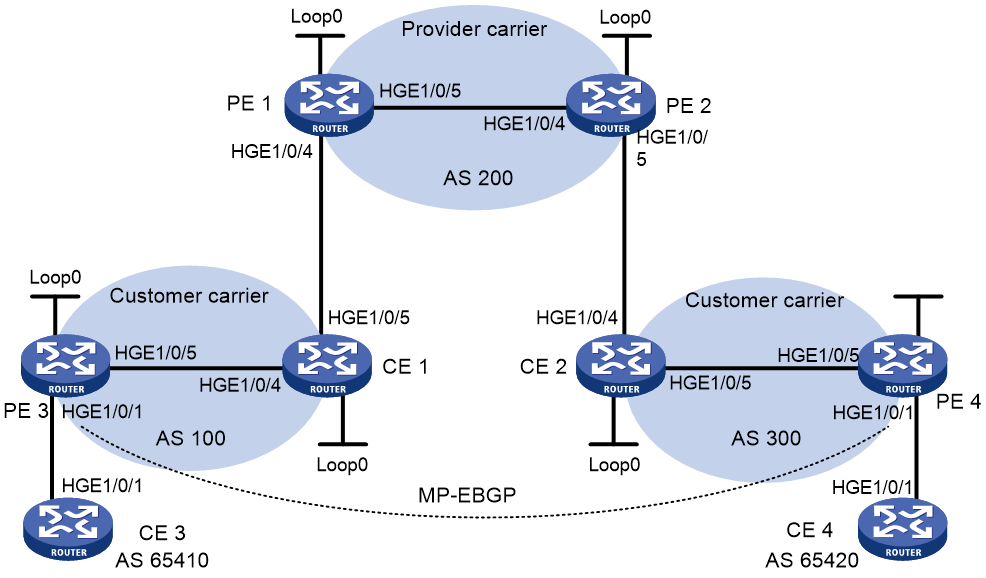
Table 9 Interface and IP address assignment
|
Device |
Interface |
IP address |
Device |
Interface |
IP address |
|
CE 3 |
HGE1/0/1 |
100.1.1.1/24 |
CE 4 |
HGE1/0/1 |
120.1.1.1/24 |
|
PE 3 |
Loop0 |
1.1.1.9/32 |
PE 4 |
Loop0 |
6.6.6.9/32 |
|
|
HGE1/0/1 |
100.1.1.2/24 |
|
HGE1/0/1 |
120.1.1.2/24 |
|
|
HGE1/0/5 |
10.1.1.1/24 |
|
HGE1/0/5 |
20.1.1.2/24 |
|
CE 1 |
Loop0 |
2.2.2.9/32 |
CE 2 |
Loop0 |
5.5.5.9/32 |
|
|
HGE1/0/4 |
10.1.1.2/24 |
|
HGE1/0/4 |
21.1.1.2/24 |
|
|
HGE1/0/5 |
11.1.1.1/24 |
|
HGE1/0/5 |
20.1.1.1/24 |
|
PE 1 |
Loop0 |
3.3.3.9/32 |
PE 2 |
Loop0 |
4.4.4.9/32 |
|
|
HGE1/0/4 |
11.1.1.2/24 |
|
HGE1/0/4 |
30.1.1.2/24 |
|
|
HGE1/0/5 |
30.1.1.1/24 |
|
HGE1/0/5 |
21.1.1.1/24 |
Procedure
1. Configure MPLS L3VPN on the provider carrier backbone. Enable IS-IS as the IGP, enable LDP between PE 1 and PE 2, and establish an MP-IBGP peer relationship between the PEs:
# Configure PE 1.
<PE1> system-view
[PE1] interface loopback 0
[PE1-LoopBack0] ip address 3.3.3.9 32
[PE1-LoopBack0] quit
[PE1] mpls lsr-id 3.3.3.9
[PE1] mpls ldp
[PE1-ldp] quit
[PE1] isis 1
[PE1-isis-1] network-entity 10.0000.0000.0000.0004.00
[PE1-isis-1] quit
[PE1] interface loopback 0
[PE1-LoopBack0] isis enable 1
[PE1-LoopBack0] quit
[PE1] interface hundredgige 1/0/5
[PE1-HundredGigE1/0/5] ip address 30.1.1.1 24
[PE1-HundredGigE1/0/5] isis enable 1
[PE1-HundredGigE1/0/5] mpls enable
[PE1-HundredGigE1/0/5] mpls ldp enable
[PE1-HundredGigE1/0/5] mpls ldp transport-address interface
[PE1-HundredGigE1/0/5] quit
[PE1] bgp 200
[PE1-bgp-default] peer 4.4.4.9 as-number 200
[PE1-bgp-default] peer 4.4.4.9 connect-interface loopback 0
[PE1-bgp-default] address-family vpnv4
[PE1-bgp-default-vpnv4] peer 4.4.4.9 enable
[PE1-bgp-default-vpnv4] quit
[PE1-bgp-default] quit
# Configure PE 2 in the same way that PE 1 is configured. (Details not shown.)
# On PE 1 or PE 2, execute the following commands:
¡ Execute the display mpls ldp peer command to verify that an LDP session in Operational state has been established between PE 1 and PE 2. (Details not shown.)
¡ Execute the display bgp peer vpnv4 command to verify that a BGP peer relationship in Established state has been established between PE 1 and PE 2. (Details not shown.)
¡ Execute the display isis peer command to verify that the IS-IS neighbor relationship has been established between PE 1 and PE 2. (Details not shown.)
2. Configure the customer carrier network. Enable IS-IS as the IGP, and enable LDP between PE 3 and CE 1, and between PE 4 and CE 2:
# Configure PE 3.
<PE3> system-view
[PE3] interface loopback 0
[PE3-LoopBack0] ip address 1.1.1.9 32
[PE3-LoopBack0] quit
[PE3] mpls lsr-id 1.1.1.9
[PE3] mpls ldp
[PE3-ldp] quit
[PE3] isis 2
[PE3-isis-2] network-entity 10.0000.0000.0000.0001.00
[PE3-isis-2] quit
[PE3] interface loopback 0
[PE3-LoopBack0] isis enable 2
[PE3-LoopBack0] quit
[PE3] interface hundredgige 1/0/5
[PE3-HundredGigE1/0/5] ip address 10.1.1.1 24
[PE3-HundredGigE1/0/5] isis enable 2
[PE3-HundredGigE1/0/5] mpls enable
[PE3-HundredGigE1/0/5] mpls ldp enable
[PE3-HundredGigE1/0/5] mpls ldp transport-address interface
[PE3-HundredGigE1/0/5] quit
# Configure CE 1.
<CE1> system-view
[CE1] interface loopback 0
[CE1-LoopBack0] ip address 2.2.2.9 32
[CE1-LoopBack0] quit
[CE1] mpls lsr-id 2.2.2.9
[CE1] mpls ldp
[CE1-ldp] import bgp
[CE1-ldp] quit
[CE1] isis 2
[CE1-isis-2] network-entity 10.0000.0000.0000.0002.00
[CE1-isis-2] address-family ipv4
[CE1-isis-2-ipv4] import-route bgp
[CE1-isis-2-ipv4] quit
[CE1-isis-2] quit
[CE1] interface loopback 0
[CE1-LoopBack0] isis enable 2
[CE1-LoopBack0] quit
[CE1] interface hundredgige 1/0/4
[CE1-HundredGigE1/0/4] ip address 10.1.1.2 24
[CE1-HundredGigE1/0/4] isis enable 2
[CE1-HundredGigE1/0/4] mpls enable
[CE1-HundredGigE1/0/4] mpls ldp enable
[CE1-HundredGigE1/0/4] mpls ldp transport-address interface
[CE1-HundredGigE1/0/4] quit
PE 3 and CE 1 can establish an LDP session and IS-IS neighbor relationship between them.
# Configure PE 4 and CE 2 in the same way that PE 3 and CE 1 are configured. (Details not shown.)
3. Allow CEs of the customer carrier to access PEs of the provider carrier:
# Configure PE 1.
[PE1] ip vpn-instance vpn1
[PE1-vpn-instance-vpn1] route-distinguisher 200:1
[PE1-vpn-instance-vpn1] vpn-target 1:1
[PE1-vpn-instance-vpn1] quit
[PE1] interface hundredgige 1/0/4
[PE1-HundredGigE1/0/4] ip binding vpn-instance vpn1
[PE1-HundredGigE1/0/4] ip address 11.1.1.2 24
[PE1-HundredGigE1/0/4] mpls enable
[PE1-HundredGigE1/0/4] quit
[PE1] bgp 200
[PE1-bgp-default] ip vpn-instance vpn1
[PE1-bgp-default-vpn1] peer 11.1.1.1 as-number 100
[PE1-bgp-default-vpn1] address-family ipv4 unicast
[PE1-bgp-default-ipv4-vpn1] peer 11.1.1.1 enable
[PE1-bgp-default-ipv4-vpn1] peer 11.1.1.1 label-route-capability
[PE1-bgp-default-ipv4-vpn1] peer 11.1.1.1 route-policy csc export
[PE1-bgp-default-ipv4-vpn1] quit
[PE1-bgp-default-vpn1] quit
[PE1-bgp-default] quit
[PE1] route-policy csc permit node 0
[PE1-route-policy-csc-0] apply mpls-label
[PE1-route-policy-csc-0] quit
# Configure CE 1.
[CE1] interface hundredgige 1/0/5
[CE1-HundredGigE1/0/5] ip address 11.1.1.1 24
[CE1-HundredGigE1/0/5] mpls enable
[CE1-HundredGigE1/0/5] quit
[CE1] bgp 100
[CE1-bgp-default] peer 11.1.1.2 as-number 200
[CE1-bgp-default] address-family ipv4 unicast
[CE1-bgp-default-ipv4] peer 11.1.1.2 enable
[CE1-bgp-default-ipv4] peer 11.1.1.2 label-route-capability
[CE1-bgp-default-ipv4] peer 11.1.1.2 route-policy csc export
[CE1-bgp-default-ipv4] import isis 2
[CE1-bgp-default-ipv4] quit
[CE1-bgp-default] quit
[CE1] route-policy csc permit node 0
[CE1-route-policy-csc-0] apply mpls-label
[CE1-route-policy-csc-0] quit
PE 1 and CE 1 can establish a BGP session and exchange labeled IPv4 unicast routes through BGP.
# Configure PE 2 and CE 2 in the same way that PE 1 and CE 1 are configured. (Details not shown.)
4. Connect CEs of the end customers and the PEs of the customer carrier:
# Configure CE 3.
<CE3> system-view
[CE3] interface hundredgige 1/0/1
[CE3-HundredGigE1/0/1] ip address 100.1.1.1 24
[CE3-HundredGigE1/0/1] quit
[CE3] bgp 65410
[CE3-bgp-default] peer 100.1.1.2 as-number 100
[CE3-bgp-default] address-family ipv4 unicast
[CE3-bgp-default-ipv4] peer 100.1.1.2 enable
[CE3-bgp-default-ipv4] import-route direct
[CE3-bgp-default-ipv4] quit
[CE3-bgp-default] quit
# Configure PE 3.
[PE3] ip vpn-instance vpn1
[PE3-vpn-instance-vpn1] route-distinguisher 100:1
[PE3-vpn-instance-vpn1] vpn-target 1:1
[PE3-vpn-instance-vpn1] quit
[PE3] interface hundredgige 1/0/1
[PE3-HundredGigE1/0/1] ip binding vpn-instance vpn1
[PE3-HundredGigE1/0/1] ip address 100.1.1.2 24
[PE3-HundredGigE1/0/1] quit
[PE3] bgp 100
[PE3-bgp-default] ip vpn-instance vpn1
[PE3-bgp-default-vpn1] peer 100.1.1.1 as-number 65410
[PE3-bgp-default-vpn1] address-family ipv4 unicast
[PE3-bgp-default-ipv4-vpn1] peer 100.1.1.1 enable
[PE3-bgp-default-ipv4-vpn1] quit
[PE3-bgp-default-vpn1] quit
[PE3-bgp-default] quit
# Configure PE 4 and CE 4 in the same way that PE 3 and CE 3 are configured. (Details not shown.)
5. Configure an MP-EBGP peer relationship between the PEs of the customer carrier to exchange the VPN routes of the end customers:
# Configure PE 3.
[PE3] bgp 100
[PE3-bgp-default] peer 6.6.6.9 as-number 300
[PE3-bgp-default] peer 6.6.6.9 connect-interface loopback 0
[PE3-bgp-default] peer 6.6.6.9 ebgp-max-hop 10
[PE3-bgp-default] address-family vpnv4
[PE3-bgp-default-vpnv4] peer 6.6.6.9 enable
[PE3-bgp-default-vpnv4] quit
[PE3-bgp-default] quit
# Configure PE 4 in the same way that PE 3 is configured. (Details not shown.)
Verifying the configuration
1. Display the public network routing table and VPN routing table on the provider carrier PEs, for example, on PE 1:
# Verify that the public network routing table contains only routes of the provider carrier network.
[PE1] display ip routing-table
Destinations : 14 Routes : 14
Destination/Mask Proto Pre Cost NextHop Interface
0.0.0.0/32 Direct 0 0 127.0.0.1 InLoop0
3.3.3.9/32 Direct 0 0 127.0.0.1 InLoop0
4.4.4.9/32 IS_L1 15 10 30.1.1.2 HGE1/0/5
30.1.1.0/24 Direct 0 0 30.1.1.1 HGE1/0/5
30.1.1.0/32 Direct 0 0 30.1.1.1 HGE1/0/5
30.1.1.1/32 Direct 0 0 127.0.0.1 InLoop0
30.1.1.255/32 Direct 0 0 30.1.1.1 HGE1/0/5
127.0.0.0/8 Direct 0 0 127.0.0.1 InLoop0
127.0.0.0/32 Direct 0 0 127.0.0.1 InLoop0
127.0.0.1/32 Direct 0 0 127.0.0.1 InLoop0
127.255.255.255/32 Direct 0 0 127.0.0.1 InLoop0
224.0.0.0/4 Direct 0 0 0.0.0.0 NULL0
224.0.0.0/24 Direct 0 0 0.0.0.0 NULL0
255.255.255.255/32 Direct 0 0 127.0.0.1 InLoop0
# Verify that the VPN routing table contains the internal routes of the customer carrier, but it does not contain the VPN routes that the customer carrier maintains.
[PE1] display ip routing-table vpn-instance vpn1
Destinations : 14 Routes : 14
Destination/Mask Proto Pre Cost NextHop Interface
0.0.0.0/32 Direct 0 0 127.0.0.1 InLoop0
1.1.1.9/32 BGP 255 10 11.1.1.1 HGE1/0/4
6.6.6.9/32 BGP 255 10 4.4.4.9 HGE1/0/5
11.1.1.0/24 Direct 0 0 11.1.1.2 HGE1/0/4
11.1.1.0/32 Direct 0 0 11.1.1.2 HGE1/0/4
11.1.1.2/32 Direct 0 0 127.0.0.1 InLoop0
11.1.1.255/32 Direct 0 0 11.1.1.2 HGE1/0/4
127.0.0.0/8 Direct 0 0 127.0.0.1 InLoop0
127.0.0.0/32 Direct 0 0 127.0.0.1 InLoop0
127.0.0.1/32 Direct 0 0 127.0.0.1 InLoop0
127.255.255.255/32 Direct 0 0 127.0.0.1 InLoop0
224.0.0.0/4 Direct 0 0 0.0.0.0 NULL0
224.0.0.0/24 Direct 0 0 0.0.0.0 NULL0
255.255.255.255/32 Direct 0 0 127.0.0.1 InLoop0
2. Display the routing table on the customer carrier CEs, for example, on CE 1.
# Verify that the routing table contains the internal routes of the customer carrier network, but it does not contain the VPN routes that the customer carrier maintains.
[CE1] display ip routing-table
Destinations : 19 Routes : 19
Destination/Mask Proto Pre Cost NextHop Interface
0.0.0.0/32 Direct 0 0 127.0.0.1 InLoop0
1.1.1.9/32 IS_L1 15 10 10.1.1.1 HGE1/0/4
2.2.2.9/32 Direct 0 0 127.0.0.1 InLoop0
6.6.6.9/32 BGP 255 0 11.1.1.2 HGE1/0/5
10.1.1.0/24 Direct 0 0 10.1.1.2 HGE1/0/4
10.1.1.0/32 Direct 0 0 10.1.1.2 HGE1/0/4
10.1.1.2/32 Direct 0 0 127.0.0.1 InLoop0
10.1.1.255/32 Direct 0 0 10.1.1.2 HGE1/0/4
11.1.1.0/24 Direct 0 0 11.1.1.1 HGE1/0/5
11.1.1.0/32 Direct 0 0 11.1.1.1 HGE1/0/5
11.1.1.1/32 Direct 0 0 127.0.0.1 InLoop0
11.1.1.255/32 Direct 0 0 11.1.1.1 HGE1/0/5
127.0.0.0/8 Direct 0 0 127.0.0.1 InLoop0
127.0.0.0/32 Direct 0 0 127.0.0.1 InLoop0
127.0.0.1/32 Direct 0 0 127.0.0.1 InLoop0
127.255.255.255/32 Direct 0 0 127.0.0.1 InLoop0
224.0.0.0/4 Direct 0 0 0.0.0.0 NULL0
224.0.0.0/24 Direct 0 0 0.0.0.0 NULL0
255.255.255.255/32 Direct 0 0 127.0.0.1 InLoop0
3. Display the public network routing table and VPN routing table on the customer carrier PEs, for example, on PE 3:
# Verify that the public network routing table contains the internal routes of the customer carrier network.
[PE3] display ip routing-table
Destinations : 15 Routes : 15
Destination/Mask Proto Pre Cost NextHop Interface
0.0.0.0/32 Direct 0 0 127.0.0.1 InLoop0
1.1.1.9/32 Direct 0 0 127.0.0.1 InLoop0
2.2.2.9/32 IS_L1 15 10 10.1.1.2 HGE1/0/5
6.6.6.9/32 IS_L2 15 74 10.1.1.2 HGE1/0/5
10.1.1.0/24 Direct 0 0 10.1.1.1 HGE1/0/5
10.1.1.0/32 Direct 0 0 10.1.1.1 HGE1/0/5
10.1.1.1/32 Direct 0 0 127.0.0.1 InLoop0
10.1.1.255/32 Direct 0 0 10.1.1.1 HGE1/0/5
127.0.0.0/8 Direct 0 0 127.0.0.1 InLoop0
127.0.0.0/32 Direct 0 0 127.0.0.1 InLoop0
127.0.0.1/32 Direct 0 0 127.0.0.1 InLoop0
127.255.255.255/32 Direct 0 0 127.0.0.1 InLoop0
224.0.0.0/4 Direct 0 0 0.0.0.0 NULL0
224.0.0.0/24 Direct 0 0 0.0.0.0 NULL0
255.255.255.255/32 Direct 0 0 127.0.0.1 InLoop0
# Verify that the VPN routing table contains the route to the remote VPN customer.
[PE3] display ip routing-table vpn-instance vpn1
Destinations : 13 Routes : 13
Destination/Mask Proto Pre Cost NextHop Interface
0.0.0.0/32 Direct 0 0 127.0.0.1 InLoop0
100.1.1.0/24 Direct 0 0 100.1.1.2 HGE1/0/1
100.1.1.0/32 Direct 0 0 100.1.1.2 HGE1/0/1
100.1.1.2/32 Direct 0 0 127.0.0.1 InLoop0
100.1.1.255/32 Direct 0 0 100.1.1.2 HGE1/0/1
127.0.0.0/8 Direct 0 0 127.0.0.1 InLoop0
127.0.0.0/32 Direct 0 0 127.0.0.1 InLoop0
127.0.0.1/32 Direct 0 0 127.0.0.1 InLoop0
127.255.255.255/32 Direct 0 0 127.0.0.1 InLoop0
120.1.1.0/24 BGP 255 0 6.6.6.9 HGE1/0/5
224.0.0.0/4 Direct 0 0 0.0.0.0 NULL0
224.0.0.0/24 Direct 0 0 0.0.0.0 NULL0
255.255.255.255/32 Direct 0 0 127.0.0.1 InLoop0
4. Verify that PE 3 and PE 4 can ping each other. (Details not shown.)
5. Verify that CE 3 and CE 4 can ping each other. (Details not shown.)
Example: Configuring nested VPN
Network configuration
The service provider provides nested VPN services for users, as shown in Figure 34.
· PE 1 and PE 2 are PE devices on the service provider backbone. Both of them support the nested VPN feature.
· CE 1 and CE 2 are provider CEs connected to the service provider backbone. Both of them support VPNv4 routes.
· PE 3 and PE 4 are PE devices of the customer VPN. Both of them support MPLS L3VPN.
· CE 3 through CE 6 are CE devices of sub-VPNs in the customer VPN.
The key of nested VPN configuration is to understand the processing of routes of sub-VPNs on the service provider PEs:
· When receiving a VPNv4 route from a provider CE (CE 1 or CE 2, in this example), a provider PE performs the following operations:
a. Replaces the RD of the VPNv4 route with the RD of the MPLS VPN on the service provider network.
b. Adds the export target attribute of the MPLS VPN on the service provider network to the extended community attribute list.
c. Forwards the VPNv4 route.
· To implement exchange of sub-VPN routes between customer PEs and service provider PEs, MP-EBGP peers must be established between provider PEs and provider CEs.
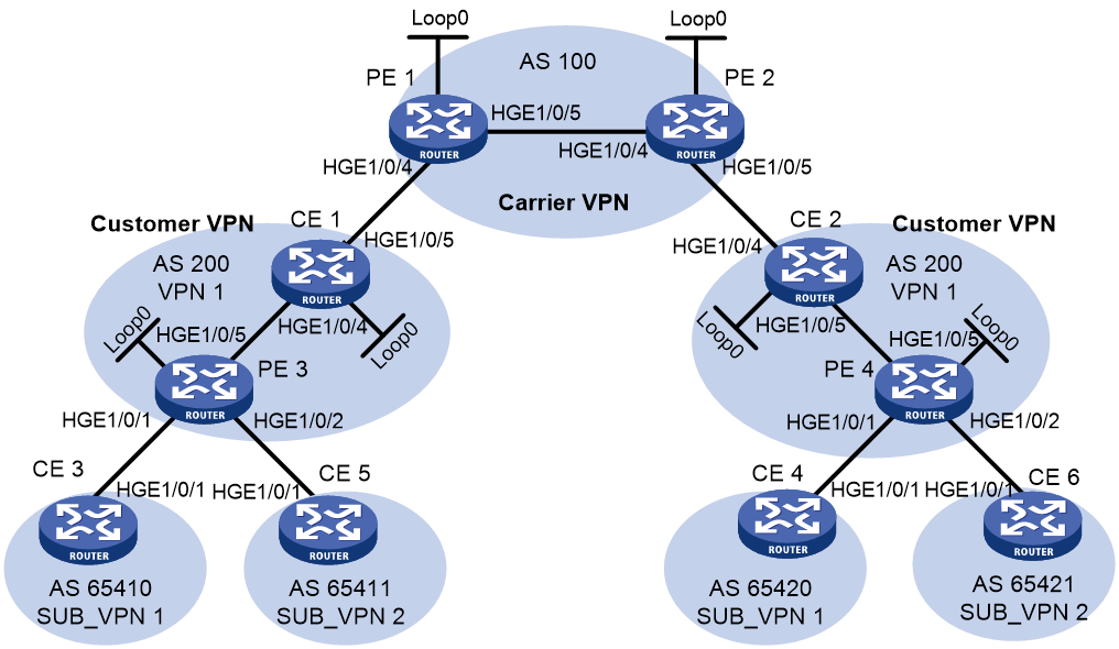
Table 10 Interface and IP address assignment
|
Device |
Interface |
IP address |
Device |
Interface |
IP address |
|
CE 1 |
Loop0 |
2.2.2.9/32 |
CE 2 |
Loop0 |
5.5.5.9/32 |
|
|
HGE1/0/4 |
10.1.1.2/24 |
|
HGE1/0/4 |
21.1.1.2/24 |
|
|
HGE1/0/5 |
11.1.1.1/24 |
|
HGE1/0/5 |
20.1.1.1/24 |
|
CE 3 |
HGE1/0/1 |
100.1.1.1/24 |
CE 4 |
HGE1/0/1 |
120.1.1.1/24 |
|
CE 5 |
HGE1/0/1 |
110.1.1.1/24 |
CE 6 |
HGE1/0/1 |
130.1.1.1/24 |
|
PE 1 |
Loop0 |
3.3.3.9/32 |
PE 2 |
Loop0 |
4.4.4.9/32 |
|
|
HGE1/0/4 |
11.1.1.2/24 |
|
HGE1/0/4 |
30.1.1.2/24 |
|
|
HGE1/0/5 |
30.1.1.1/24 |
|
HGE1/0/5 |
21.1.1.1/24 |
|
PE 3 |
Loop0 |
1.1.1.9/32 |
PE 4 |
Loop0 |
6.6.6.9/32 |
|
|
HGE1/0/1 |
100.1.1.2/24 |
|
HGE1/0/1 |
120.1.1.2/24 |
|
|
HGE1/0/2 |
110.1.1.2/24 |
|
HGE1/0/2 |
130.1.1.2/24 |
|
|
HGE1/0/5 |
10.1.1.1/24 |
|
HGE1/0/5 |
20.1.1.2/24 |
Procedure
1. Configure MPLS L3VPN on the service provider backbone. Enable IS-IS, enable LDP, and establish an MP-IBGP peer relationship between PE 1 and PE 2:
# Configure PE 1.
<PE1> system-view
[PE1] interface loopback 0
[PE1-LoopBack0] ip address 3.3.3.9 32
[PE1-LoopBack0] quit
[PE1] mpls lsr-id 3.3.3.9
[PE1] mpls ldp
[PE1-ldp] quit
[PE1] isis 1
[PE1-isis-1] network-entity 10.0000.0000.0000.0004.00
[PE1-isis-1] quit
[PE1] interface loopback 0
[PE1-LoopBack0] isis enable 1
[PE1-LoopBack0] quit
[PE1] interface hundredgige 1/0/5
[PE1-HundredGigE1/0/5] ip address 30.1.1.1 24
[PE1-HundredGigE1/0/5] isis enable 1
[PE1-HundredGigE1/0/5] mpls enable
[PE1-HundredGigE1/0/5] mpls ldp enable
[PE1-HundredGigE1/0/5] mpls ldp transport-address interface
[PE1-HundredGigE1/0/5] quit
[PE1] bgp 100
[PE1-bgp-default] peer 4.4.4.9 as-number 100
[PE1-bgp-default] peer 4.4.4.9 connect-interface loopback 0
[PE1-bgp-default] address-family vpnv4
[PE1-bgp-default-vpnv4] peer 4.4.4.9 enable
[PE1-bgp-default-vpnv4] quit
[PE1-bgp-default] quit
# Configure PE 2 in the same way that PE 1 is configured. (Details not shown.)
# On PE 1 or PE 2, execute the following commands:
¡ Execute the display mpls ldp peer command to verify that an LDP session in Operational state has been established between PE 1 and PE 2. (Details not shown.)
¡ Execute the display bgp peer vpnv4 command to verify that a BGP peer relationship in Established state has been established between PE 1 and PE 2. (Details not shown.)
¡ Execute the display isis peer command to verify that the IS-IS neighbor relationship has been established between PE 1 and PE 2. (Details not shown.)
2. Configure the customer VPN. Enable IS-IS, and enable LDP between PE 3 and CE 1, and between PE 4 and CE 2:
# Configure PE 3.
<PE3> system-view
[PE3] interface loopback 0
[PE3-LoopBack0] ip address 1.1.1.9 32
[PE3-LoopBack0] quit
[PE3] mpls lsr-id 1.1.1.9
[PE3] mpls ldp
[PE3-ldp] quit
[PE3] isis 2
[PE3-isis-2] network-entity 10.0000.0000.0000.0001.00
[PE3-isis-2] quit
[PE3] interface loopback 0
[PE3-LoopBack0] isis enable 2
[PE3-LoopBack0] quit
[PE3] interface hundredgige 1/0/5
[PE3-HundredGigE1/0/5] ip address 10.1.1.1 24
[PE3-HundredGigE1/0/5] isis enable 2
[PE3-HundredGigE1/0/5] mpls enable
[PE3-HundredGigE1/0/5] mpls ldp enable
[PE3-HundredGigE1/0/5] quit
# Configure CE 1.
<CE1> system-view
[CE1] interface loopback 0
[CE1-LoopBack0] ip address 2.2.2.9 32
[CE1-LoopBack0] quit
[CE1] mpls lsr-id 2.2.2.9
[CE1] mpls ldp
[CE1-ldp] quit
[CE1] isis 2
[CE1-isis-2] network-entity 10.0000.0000.0000.0002.00
[CE1-isis-2] quit
[CE1] interface loopback 0
[CE1-LoopBack0] isis enable 2
[CE1-LoopBack0] quit
[CE1] interface hundredgige 1/0/4
[CE1-HundredGigE1/0/4] ip address 10.1.1.2 24
[CE1-HundredGigE1/0/4] isis enable 2
[CE1-HundredGigE1/0/4] mpls enable
[CE1-HundredGigE1/0/4] mpls ldp enable
[CE1-HundredGigE1/0/4] quit
An LDP session and IS-IS neighbor relationship can be established between PE 3 and CE 1.
# Configure PE 4 and CE 2 in the same way that PE 3 and CE 1 are configured. (Details not shown.)
3. Connect CE 1 and CE 2 to service provider PEs:
# Configure PE 1.
[PE1] ip vpn-instance vpn1
[PE1-vpn-instance-vpn1] route-distinguisher 200:1
[PE1-vpn-instance-vpn1] vpn-target 1:1
[PE1-vpn-instance-vpn1] quit
[PE1] interface hundredgige 1/0/4
[PE1-HundredGigE1/0/4] ip binding vpn-instance vpn1
[PE1-HundredGigE1/0/4] ip address 11.1.1.2 24
[PE1-HundredGigE1/0/4] mpls enable
[PE1-HundredGigE1/0/4] quit
[PE1] bgp 100
[PE1-bgp-default] ip vpn-instance vpn1
[PE1-bgp-default-vpn1] peer 11.1.1.1 as-number 200
[PE1-bgp-default-vpn1] address-family ipv4
[PE1-bgp-default-ipv4-vpn1] peer 11.1.1.1 enable
[PE1-bgp-default-ipv4-vpn1] quit
[PE1-bgp-default-vpn1] quit
[PE1-bgp-default] quit
# Configure CE 1.
[CE1] interface hundredgige 1/0/5
[CE1-HundredGigE1/0/5] ip address 11.1.1.1 24
[CE1-HundredGigE1/0/5] mpls enable
[CE1-HundredGigE1/0/5] quit
[CE1] bgp 200
[CE1-bgp-default] peer 11.1.1.2 as-number 100
[CE1-bgp-default] address-family ipv4
[CE1-bgp-default-ipv4] peer 11.1.1.2 enable
[CE1-bgp-default-ipv4] quit
[CE1-bgp-default] quit
# Configure PE 2 and CE 2 in the same way that PE 1 and CE 1 are configured. (Details not shown.)
4. Connect sub-VPN CEs to the customer VPN PEs:
# Configure CE 3.
<CE3> system-view
[CE3] interface hundredgige 1/0/1
[CE3-HundredGigE1/0/1] ip address 100.1.1.1 24
[CE3-HundredGigE1/0/1] quit
[CE3] bgp 65410
[CE3-bgp-default] peer 100.1.1.2 as-number 200
[CE3-bgp-default] address-family ipv4 unicast
[CE3-bgp-default-ipv4] peer 100.1.1.2 enable
[CE3-bgp-default-ipv4] import-route direct
[CE3-bgp-default-ipv4] quit
[CE3-bgp-default] quit
# Configure CE 5.
<CE5> system-view
[CE5] interface hundredgige 1/0/1
[CE5-HundredGigE1/0/1] ip address 110.1.1.1 24
[CE5-HundredGigE1/0/1] quit
[CE5] bgp 65411
[CE5-bgp-default] peer 110.1.1.2 as-number 200
[CE5-bgp-default] address-family ipv4 unicast
[CE5-bgp-default-ipv4] peer 110.1.1.2 enable
[CE5-bgp-default-ipv4] import-route direct
[CE5-bgp-default-ipv4] quit
[CE5-bgp-default] quit
# Configure PE 3.
[PE3] ip vpn-instance SUB_VPN1
[PE3-vpn-instance-SUB_VPN1] route-distinguisher 100:1
[PE3-vpn-instance-SUB_VPN1] vpn-target 2:1
[PE3-vpn-instance-SUB_VPN1] quit
[PE3] interface hundredgige 1/0/1
[PE3-HundredGigE1/0/1] ip binding vpn-instance SUB_VPN1
[PE3-HundredGigE1/0/1] ip address 100.1.1.2 24
[PE3-HundredGigE1/0/1] quit
[PE3] ip vpn-instance SUB_VPN2
[PE3-vpn-instance-SUB_VPN2] route-distinguisher 101:1
[PE3-vpn-instance-SUB_VPN2] vpn-target 2:2
[PE3-vpn-instance-SUB_VPN2] quit
[PE3] interface hundredgige 1/0/2
[PE3-HundredGigE1/0/2] ip binding vpn-instance SUB_VPN2
[PE3-HundredGigE1/0/2] ip address 110.1.1.2 24
[PE3-HundredGigE1/0/2] quit
[PE3] bgp 200
[PE3-bgp-default] ip vpn-instance SUB_VPN1
[PE3-bgp-default-SUB_VPN1] peer 100.1.1.1 as-number 65410
[PE3-bgp-default-SUB_VPN1] address-family ipv4 unicast
[PE3-bgp-default-ipv4-SUB_VPN1] peer 100.1.1.1 enable
[PE3-bgp-default-ipv4-SUB_VPN1] quit
[PE3-bgp-default-SUB_VPN1] quit
[PE3-bgp-default] ip vpn-instance SUB_VPN2
[PE3-bgp-default-SUB_VPN2] peer 110.1.1.1 as-number 65411
[PE3-bgp-default-SUB_VPN2] address-family ipv4 unicast
[PE3-bgp-default-ipv4-SUB_VPN2] peer 110.1.1.1 enable
[PE3-bgp-default-ipv4-SUB_VPN2] quit
[PE3-bgp-default-SUB_VPN2] quit
[PE3-bgp-default] quit
# Configure PE 4, CE 4 and CE 6 in the same way that PE 3, CE 3, and CE 5 are configured. (Details not shown.)
5. Establish MP-EBGP peer relationship between service provider PEs and their CEs to exchange user VPNv4 routes:
# On PE 1, enable nested VPN, and enable VPNv4 route exchange with CE 1.
[PE1] bgp 100
[PE1-bgp-default] address-family vpnv4
[PE1-bgp-default-vpnv4] nesting-vpn
[PE1-bgp-default-vpnv4] quit
[PE1-bgp-default] ip vpn-instance vpn1
[PE1-bgp-default-vpn1] address-family vpnv4
[PE1-bgp-default-vpnv4-vpn1] peer 11.1.1.1 enable
[PE1-bgp-default-vpnv4-vpn1] quit
[PE1-bgp-default-vpn1] quit
[PE1-bgp-default] quit
# On CE 1, enable VPNv4 route exchange with PE 1.
[CE1] bgp 200
[CE1-bgp-default] address-family vpnv4
[CE1-bgp-default-vpnv4] peer 11.1.1.2 enable
# Allow the local AS number to appear in the AS-PATH attribute of the routes received.
[CE1-bgp-default-vpnv4] peer 11.1.1.2 allow-as-loop 2
# Disable route target based filtering of received VPNv4 routes.
[CE1-bgp-default-vpnv4] undo policy vpn-target
[CE1-bgp-default-vpnv4] quit
[CE1-bgp-default] quit
# Configure PE 2 and CE 2 in the same way that PE 1 and CE 1 are configured. (Details not shown.)
6. Establish MP-IBGP peer relationships between sub-VPN PEs and CEs of the customer VPN to exchange VPNv4 routes of sub-VPNs:
# Configure PE 3.
[PE3] bgp 200
[PE3-bgp-default] peer 2.2.2.9 as-number 200
[PE3-bgp-default] peer 2.2.2.9 connect-interface loopback 0
[PE3-bgp-default] address-family vpnv4
[PE3-bgp-default-vpnv4] peer 2.2.2.9 enable
# Allow the local AS number to appear in the AS-PATH attribute of the routes received.
[PE3-bgp-default-vpnv4] peer 2.2.2.9 allow-as-loop 2
[PE3-bgp-default-vpnv4] quit
[PE3-bgp-default] quit
# Configure CE 1.
[CE1] bgp 200
[CE1-bgp-default] peer 1.1.1.9 as-number 200
[CE1-bgp-default] peer 1.1.1.9 connect-interface loopback 0
[CE1-bgp-default] address-family vpnv4
[CE1-bgp-default-vpnv4] peer 1.1.1.9 enable
[CE1-bgp-default-vpnv4] undo policy vpn-target
[CE1-bgp-default-vpnv4] quit
[CE1-bgp-default] quit
# Configure PE 4 and CE 2 in the same way that PE 3 and CE 1 are configured. (Details not shown.)
Verifying the configuration
1. Display the public routing table and VPN routing table on the provider PEs, for example, on PE 1:
# Verify that the public routing table contains only routes on the service provider network.
[PE1] display ip routing-table
Destinations : 14 Routes : 14
Destination/Mask Proto Pre Cost NextHop Interface
0.0.0.0/32 Direct 0 0 127.0.0.1 InLoop0
3.3.3.9/32 Direct 0 0 127.0.0.1 InLoop0
4.4.4.9/32 IS_L1 15 10 30.1.1.2 HGE1/0/5
30.1.1.0/24 Direct 0 0 30.1.1.1 HGE1/0/5
30.1.1.0/32 Direct 0 0 30.1.1.1 HGE1/0/5
30.1.1.1/32 Direct 0 0 127.0.0.1 InLoop0
30.1.1.255/32 Direct 0 0 30.1.1.1 HGE1/0/5
127.0.0.0/8 Direct 0 0 127.0.0.1 InLoop0
127.0.0.0/32 Direct 0 0 127.0.0.1 InLoop0
127.0.0.1/32 Direct 0 0 127.0.0.1 InLoop0
127.255.255.255/32 Direct 0 0 127.0.0.1 InLoop0
224.0.0.0/4 Direct 0 0 0.0.0.0 NULL0
224.0.0.0/24 Direct 0 0 0.0.0.0 NULL0
255.255.255.255/32 Direct 0 0 127.0.0.1 InLoop0
# Verify that the VPN routing table contains sub-VPN routes.
[PE1] display ip routing-table vpn-instance vpn1
Destinations : 16 Routes : 16
Destination/Mask Proto Pre Cost NextHop Interface
0.0.0.0/32 Direct 0 0 127.0.0.1 InLoop0
11.1.1.0/24 Direct 0 0 11.1.1.2 HGE1/0/4
11.1.1.0/32 Direct 0 0 11.1.1.2 HGE1/0/4
11.1.1.2/32 Direct 0 0 127.0.0.1 InLoop0
11.1.1.255/32 Direct 0 0 11.1.1.2 HGE1/0/4
100.1.1.0/24 BGP 255 0 11.1.1.1 HGE1/0/4
110.1.1.0/24 BGP 255 0 11.1.1.1 HGE1/0/4
120.1.1.0/24 BGP 255 0 4.4.4.9 HGE1/0/5
127.0.0.0/8 Direct 0 0 127.0.0.1 InLoop0
127.0.0.0/32 Direct 0 0 127.0.0.1 InLoop0
127.0.0.1/32 Direct 0 0 127.0.0.1 InLoop0
127.255.255.255/32 Direct 0 0 127.0.0.1 InLoop0
130.1.1.0/24 BGP 255 0 4.4.4.9 HGE1/0/5
224.0.0.0/4 Direct 0 0 0.0.0.0 NULL0
224.0.0.0/24 Direct 0 0 0.0.0.0 NULL0
255.255.255.255/32 Direct 0 0 127.0.0.1 InLoop0
2. Display the VPNv4 routing table on the provider CEs, for example, on CE 1.
# Verify that the VPNv4 routing table on the customer VPN contains internal sub-VPN routes.
[CE1] display bgp routing-table vpnv4
BGP local router ID is 2.2.2.9
Status codes: * - valid, > - best, d - dampened, h - history,
s - suppressed, S - stale, i - internal, e - external
Origin: i - IGP, e - EGP, ? - incomplete
Total number of routes from all PEs: 4
Route distinguisher: 100:1
Total number of routes: 1
Network NextHop MED LocPrf PrefVal Path/Ogn
* >i 100.1.1.0/24 1.1.1.9 0 100 0 200 65410?
Route distinguisher: 101:1
Total number of routes: 1
Network NextHop MED LocPrf PrefVal Path/Ogn
* >i 110.1.1.0/24 1.1.1.9 0 100 0 200 65411?
Route distinguisher: 200:1
Total number of routes: 1
Network NextHop MED LocPrf PrefVal Path/Ogn
* >e 120.1.1.0/24 11.1.1.2 0 100 200
65420?
Route Distinguisher: 201:1
Total number of routes: 1
Network NextHop MED LocPrf PrefVal Path/Ogn
* >e 130.1.1.0/24 11.1.1.2 0 100 200
65421?
3. Display the VPN routing table on the customer PEs, for example, on PE 3:
# Verify that the VPN routing table contains routes sent by the provider PE to the sub-VPN.
[PE3] display ip routing-table vpn-instance SUB_VPN1
Destinations : 13 Routes : 13
Destination/Mask Proto Pre Cost NextHop Interface
0.0.0.0/32 Direct 0 0 127.0.0.1 InLoop0
100.1.1.0/24 Direct 0 0 100.1.1.2 HGE1/0/1
100.1.1.0/32 Direct 0 0 100.1.1.2 HGE1/0/1
100.1.1.2/32 Direct 0 0 127.0.0.1 InLoop0
100.1.1.255/32 Direct 0 0 100.1.1.2 HGE1/0/1
120.1.1.0/24 BGP 255 0 2.2.2.9 HGE1/0/5
127.0.0.0/8 Direct 0 0 127.0.0.1 InLoop0
127.0.0.0/32 Direct 0 0 127.0.0.1 InLoop0
127.0.0.1/32 Direct 0 0 127.0.0.1 InLoop0
127.255.255.255/32 Direct 0 0 127.0.0.1 InLoop0
224.0.0.0/4 Direct 0 0 0.0.0.0 NULL0
224.0.0.0/24 Direct 0 0 0.0.0.0 NULL0
255.255.255.255/32 Direct 0 0 127.0.0.1 InLoop0
4. Display the routing table on the CEs of sub-VPNs in the customer VPN, for example, on CE 3 and CE 5:
# Verify that the routing table contains the route to the remote sub-VPN on CE 3.
[CE3] display ip routing-table
Destinations : 13 Routes : 13
Destination/Mask Proto Pre Cost NextHop Interface
0.0.0.0/32 Direct 0 0 127.0.0.1 InLoop0
100.1.1.0/24 Direct 0 0 100.1.1.1 HGE1/0/1
100.1.1.0/32 Direct 0 0 100.1.1.1 HGE1/0/1
100.1.1.1/32 Direct 0 0 127.0.0.1 InLoop0
100.1.1.255/24 Direct 0 0 100.1.1.1 HGE1/0/1
120.1.1.0/24 BGP 255 0 100.1.1.2 HGE1/0/1
127.0.0.0/8 Direct 0 0 127.0.0.1 InLoop0
127.0.0.0/32 Direct 0 0 127.0.0.1 InLoop0
127.0.0.1/32 Direct 0 0 127.0.0.1 InLoop0
127.255.255.255/32 Direct 0 0 127.0.0.1 InLoop0
224.0.0.0/4 Direct 0 0 0.0.0.0 NULL0
224.0.0.0/24 Direct 0 0 0.0.0.0 NULL0
255.255.255.255/32 Direct 0 0 127.0.0.1 InLoop0
# Verify that the routing table contains the route to the remote sub-VPN on CE 5.
[CE5] display ip routing-table
Destinations : 13 Routes : 13
Destination/Mask Proto Pre Cost NextHop Interface
0.0.0.0/32 Direct 0 0 127.0.0.1 InLoop0
110.1.1.0/24 Direct 0 0 110.1.1.1 HGE1/0/1
110.1.1.0/32 Direct 0 0 110.1.1.1 HGE1/0/1
110.1.1.1/32 Direct 0 0 127.0.0.1 InLoop0
110.1.1.255/32 Direct 0 0 110.1.1.1 HGE1/0/1
127.0.0.0/8 Direct 0 0 127.0.0.1 InLoop0
127.0.0.0/32 Direct 0 0 127.0.0.1 InLoop0
127.0.0.1/32 Direct 0 0 127.0.0.1 InLoop0
127.255.255.255/32 Direct 0 0 127.0.0.1 InLoop0
130.1.1.0/24 BGP 255 0 110.1.1.2 HGE1/0/1
224.0.0.0/4 Direct 0 0 0.0.0.0 NULL0
224.0.0.0/24 Direct 0 0 0.0.0.0 NULL0
255.255.255.255/32 Direct 0 0 127.0.0.1 InLoop0
5. Verify that CE 3 and CE 4 can ping each other. (Details not shown.)
6. Verify that CE 5 and CE 6 can ping each other. (Details not shown.)
7. Verify that CE 3 and CE 6 cannot ping each other. (Details not shown.)
Example: Configuring HoVPN
Network configuration
As shown in Figure 35, there are two levels of networks: the backbone and the MPLS VPN networks.
· SPEs act as PEs to allow MPLS VPNs to access the backbone.
· UPEs act as PEs of the MPLS VPNs to allow end users to access the VPNs.
· Performance requirements for the UPEs are lower than those for the SPEs.
· SPEs advertise routes permitted by routing policies to UPEs, permitting CE 1 and CE 3 in VPN 1 to communicate with each other and forbidding CE 2 and CE 4 in VPN 2 from communicating with each other.
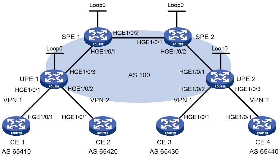
Table 11 Interface and IP address assignment
|
Interface |
IP address |
Device |
Interface |
IP address |
|
|
CE 1 |
HGE1/0/1 |
10.2.1.1/24 |
CE 3 |
HGE1/0/1 |
10.1.1.1/24 |
|
CE 2 |
HGE1/0/1 |
10.4.1.1/24 |
CE 4 |
HGE1/0/1 |
10.3.1.1/24 |
|
UPE 1 |
Loop0 |
1.1.1.9/32 |
UPE 2 |
Loop0 |
4.4.4.9/32 |
|
|
HGE1/0/1 |
10.2.1.2/24 |
|
HGE1/0/1 |
172.2.1.1/24 |
|
|
HGE1/0/2 |
10.4.1.2/24 |
|
HGE1/0/2 |
10.1.1.2/24 |
|
|
HGE1/0/3 |
172.1.1.1/24 |
|
HGE1/0/3 |
10.3.1.2/24 |
|
SPE 1 |
Loop0 |
2.2.2.9/32 |
SPE 2 |
Loop0 |
3.3.3.9/32 |
|
|
HGE1/0/1 |
172.1.1.2/24 |
|
HGE1/0/1 |
180.1.1.2/24 |
|
|
HGE1/0/2 |
180.1.1.1/24 |
|
HGE1/0/2 |
172.2.1.2/24 |
Procedure
1. Configure UPE 1:
# Configure basic MPLS and MPLS LDP to establish LDP LSPs.
<UPE1> system-view
[UPE1] interface loopback 0
[UPE1-LoopBack0] ip address 1.1.1.9 32
[UPE1-LoopBack0] quit
[UPE1] mpls lsr-id 1.1.1.9
[UPE1] mpls ldp
[UPE1-ldp] quit
[UPE1] interface hundredgige 1/0/3
[UPE1-HundredGigE1/0/3] ip address 172.1.1.1 24
[UPE1-HundredGigE1/0/3] mpls enable
[UPE1-HundredGigE1/0/3] mpls ldp enable
[UPE1-HundredGigE1/0/3] quit
# Configure the IGP protocol (OSPF, in this example).
[UPE1] ospf
[UPE1-ospf-1] area 0
[UPE1-ospf-1-area-0.0.0.0] network 172.1.1.0 0.0.0.255
[UPE1-ospf-1-area-0.0.0.0] network 1.1.1.9 0.0.0.0
[UPE1-ospf-1-area-0.0.0.0] quit
[UPE1-ospf-1] quit
# Configure VPN instances vpn1 and vpn2, allowing CE 1 and CE 2 to access UPE 1.
[UPE1] ip vpn-instance vpn1
[UPE1-vpn-instance-vpn1] route-distinguisher 100:1
[UPE1-vpn-instance-vpn1] vpn-target 100:1 both
[UPE1-vpn-instance-vpn1] quit
[UPE1] ip vpn-instance vpn2
[UPE1-vpn-instance-vpn2] route-distinguisher 100:2
[UPE1-vpn-instance-vpn2] vpn-target 100:2 both
[UPE1-vpn-instance-vpn2] quit
[UPE1] interface hundredgige 1/0/1
[UPE1-HundredGigE1/0/1] ip binding vpn-instance vpn1
[UPE1-HundredGigE1/0/1] ip address 10.2.1.2 24
[UPE1-HundredGigE1/0/1] quit
[UPE1] interface hundredgige 1/0/2
[UPE1-HundredGigE1/0/2] ip binding vpn-instance vpn2
[UPE1-HundredGigE1/0/2] ip address 10.4.1.2 24
[UPE1-HundredGigE1/0/2] quit
# Establish an MP-IBGP peer relationship with SPE 1.
[UPE1] bgp 100
[UPE1-bgp-default] peer 2.2.2.9 as-number 100
[UPE1-bgp-default] peer 2.2.2.9 connect-interface loopback 0
[UPE1-bgp-default] address-family vpnv4
[UPE1-bgp-default-vpnv4] peer 2.2.2.9 enable
[UPE1-bgp-default-vpnv4] quit
# Establish an EBGP peer relationship with CE 1.
[UPE1-bgp-default] ip vpn-instance vpn1
[UPE1-bgp-default-vpn1] peer 10.2.1.1 as-number 65410
[UPE1-bgp-default-vpn1] address-family ipv4 unicast
[UPE1-bgp-default-ipv4-vpn1] peer 10.2.1.1 enable
[UPE1-bgp-default-ipv4-vpn1] quit
[UPE1-bgp-default-vpn1] quit
# Establish an EBGP peer relationship with CE 2.
[UPE1-bgp-default] ip vpn-instance vpn2
[UPE1-bgp-default-vpn2] peer 10.4.1.1 as-number 65420
[UPE1-bgp-default-vpn2] address-family ipv4 unicast
[UPE1-bgp-default-ipv4-vpn2] peer 10.4.1.1 enable
[UPE1-bgp-default-ipv4-vpn2] quit
[UPE1-bgp-default-vpn2] quit
[UPE1-bgp-default] quit
2. Configure CE 1.
<CE1> system-view
[CE1] interface hundredgige 1/0/1
[CE1-HundredGigE1/0/1] ip address 10.2.1.1 255.255.255.0
[CE1-HundredGigE1/0/1] quit
[CE1] bgp 65410
[CE1-bgp-default] peer 10.2.1.2 as-number 100
[CE1-bgp-default] address-family ipv4 unicast
[CE1-bgp-default-ipv4] peer 10.2.1.2 enable
[CE1-bgp-default-ipv4] import-route direct
[CE1-bgp-default-ipv4] quit
[CE1-bgp-default] quit
3. Configure CE 2.
<CE2> system-view
[CE2] interface hundredgige 1/0/1
[CE2-HundredGigE1/0/1] ip address 10.4.1.1 255.255.255.0
[CE2-HundredGigE1/0/1] quit
[CE2] bgp 65420
[CE2-bgp-default] peer 10.4.1.2 as-number 100
[CE2-bgp-default] address-family ipv4 unicast
[CE2-bgp-default-ipv4] peer 10.4.1.2 enable
[CE2-bgp-default-ipv4] import-route direct
[CE2-bgp-default-ipv4] quit
[CE2-bgp-default] quit
4. Configure UPE 2:
# Configure basic MPLS and MPLS LDP to establish LDP LSPs.
<UPE2> system-view
[UPE2] interface loopback 0
[UPE2-LoopBack0] ip address 4.4.4.9 32
[UPE2-LoopBack0] quit
[UPE2] mpls lsr-id 4.4.4.9
[UPE2] mpls ldp
[UPE2-ldp] quit
[UPE2] interface hundredgige 1/0/1
[UPE2-HundredGigE1/0/1] ip address 172.2.1.1 24
[UPE2-HundredGigE1/0/1] mpls enable
[UPE2-HundredGigE1/0/1] mpls ldp enable
[UPE2-HundredGigE1/0/1] quit
# Configure the IGP protocol (OSPF, in this example).
[UPE2] ospf
[UPE2-ospf-1] area 0
[UPE2-ospf-1-area-0.0.0.0] network 172.2.1.0 0.0.0.255
[UPE2-ospf-1-area-0.0.0.0] network 4.4.4.9 0.0.0.0
[UPE2-ospf-1-area-0.0.0.0] quit
[UPE2-ospf-1] quit
# Configure VPN instances vpn1 and vpn2, allowing CE 3 and CE 4 to access UPE 2.
[UPE2] ip vpn-instance vpn1
[UPE2-vpn-instance-vpn1] route-distinguisher 300:1
[UPE2-vpn-instance-vpn1] vpn-target 100:1 both
[UPE2-vpn-instance-vpn1] quit
[UPE2] ip vpn-instance vpn2
[UPE2-vpn-instance-vpn2] route-distinguisher 400:2
[UPE2-vpn-instance-vpn2] vpn-target 100:2 both
[UPE2-vpn-instance-vpn2] quit
[UPE2] interface hundredgige 1/0/2
[UPE2-HundredGigE1/0/2] ip binding vpn-instance vpn1
[UPE2-HundredGigE1/0/2] ip address 10.1.1.2 24
[UPE2-HundredGigE1/0/2] quit
[UPE2] interface hundredgige 1/0/3
[UPE2-HundredGigE1/0/3] ip binding vpn-instance vpn2
[UPE2-HundredGigE1/0/3] ip address 10.3.1.2 24
[UPE2-HundredGigE1/0/3] quit
# Establish an MP-IBGP peer relationship with SPE 2.
[UPE2] bgp 100
[UPE2-bgp-default] peer 3.3.3.9 as-number 100
[UPE2-bgp-default] peer 3.3.3.9 connect-interface loopback 0
[UPE2-bgp-default] address-family vpnv4
[UPE2-bgp-default-vpnv4] peer 3.3.3.9 enable
[UPE2-bgp-default-vpnv4] quit
# Establish an EBGP peer relationship with CE 3.
[UPE2-bgp-default] ip vpn-instance vpn1
[UPE2-bgp-default-vpn1] peer 10.1.1.1 as-number 65430
[UPE2-bgp-default-vpn1] address-family ipv4 unicast
[UPE2-bgp-default-ipv4-vpn1] peer 10.1.1.1 enable
[UPE2-bgp-default-ipv4-vpn1] quit
[UPE2-bgp-default-vpn1] quit
# Establish an EBGP peer relationship with CE 4.
[UPE2-bgp-default] ip vpn-instance vpn2
[UPE2-bgp-default-vpn2] peer 10.3.1.1 as-number 65440
[UPE2-bgp-default-vpn2] address-family ipv4 unicast
[UPE2-bgp-default-ipv4-vpn2] peer 10.3.1.1 enable
[UPE2-bgp-default-ipv4-vpn2] quit
[UPE2-bgp-default-vpn2] quit
[UPE2-bgp-default] quit
5. Configure CE 3.
<CE3> system-view
[CE3] interface hundredgige 1/0/1
[CE3-HundredGigE1/0/1] ip address 10.1.1.1 255.255.255.0
[CE3-HundredGigE1/0/1] quit
[CE3] bgp 65430
[CE3-bgp-default] peer 10.1.1.2 as-number 100
[CE3-bgp-default] address-family ipv4 unicast
[CE3-bgp-default-ipv4] peer 10.1.1.2 enable
[CE3-bgp-default-ipv4] import-route direct
[CE3-bgp-default-ipv4] quit
[CE3-bgp-default] quit
6. Configure CE 4.
<CE4> system-view
[CE4] interface hundredgige 1/0/1
[CE4-HundredGigE1/0/1] ip address 10.3.1.1 255.255.255.0
[CE4-HundredGigE1/0/1] quit
[CE4] bgp 65440
[CE4-bgp-default] peer 10.3.1.2 as-number 100
[CE4-bgp-default] address-family ipv4 unicast
[CE4-bgp-default-ipv4] peer 10.3.1.2 enable
[CE4-bgp-default-ipv4] import-route direct
[CE4-bgp-default-ipv4] quit
[CE4-bgp-default] quit
7. Configure SPE 1:
# Configure basic MPLS and MPLS LDP to establish LDP LSPs.
<SPE1> system-view
[SPE1] interface loopback 0
[SPE1-LoopBack0] ip address 2.2.2.9 32
[SPE1-LoopBack0] quit
[SPE1] mpls lsr-id 2.2.2.9
[SPE1] mpls ldp
[SPE1-ldp] quit
[SPE1] interface hundredgige 1/0/1
[SPE1-HundredGigE1/0/1] ip address 172.1.1.2 24
[SPE1-HundredGigE1/0/1] mpls enable
[SPE1-HundredGigE1/0/1] mpls ldp enable
[SPE1-HundredGigE1/0/1] quit
[SPE1] interface hundredgige 1/0/2
[SPE1-HundredGigE1/0/2] ip address 180.1.1.1 24
[SPE1-HundredGigE1/0/2] mpls enable
[SPE1-HundredGigE1/0/2] mpls ldp enable
[SPE1-HundredGigE1/0/2] quit
# Configure the IGP protocol, OSPF, in this example.
[SPE1] ospf
[SPE1-ospf-1] area 0
[SPE1-ospf-1-area-0.0.0.0] network 2.2.2.9 0.0.0.0
[SPE1-ospf-1-area-0.0.0.0] network 172.1.1.0 0.0.0.255
[SPE1-ospf-1-area-0.0.0.0] network 180.1.1.0 0.0.0.255
[SPE1-ospf-1-area-0.0.0.0] quit
[SPE1-ospf-1] quit
# Configure VPN instances vpn1 and vpn2.
[SPE1] ip vpn-instance vpn1
[SPE1-vpn-instance-vpn1] route-distinguisher 500:1
[SPE1-vpn-instance-vpn1] vpn-target 100:1 both
[SPE1-vpn-instance-vpn1] quit
[SPE1] ip vpn-instance vpn2
[SPE1-vpn-instance-vpn2] route-distinguisher 700:1
[SPE1-vpn-instance-vpn2] vpn-target 100:2 both
[SPE1-vpn-instance-vpn2] quit
# Establish MP-IBGP peer relationships with SPE 2 and UPE 1, and specify UPE 1 as a UPE.
[SPE1] bgp 100
[SPE1-bgp-default] peer 1.1.1.9 as-number 100
[SPE1-bgp-default] peer 1.1.1.9 connect-interface loopback 0
[SPE1-bgp-default] peer 3.3.3.9 as-number 100
[SPE1-bgp-default] peer 3.3.3.9 connect-interface loopback 0
[SPE1-bgp-default] address-family vpnv4
[SPE1-bgp-default-vpnv4] peer 3.3.3.9 enable
[SPE1-bgp-default-vpnv4] peer 1.1.1.9 enable
[SPE1-bgp-default-vpnv4] peer 1.1.1.9 upe
[SPE1-bgp-default-vpnv4] peer 1.1.1.9 next-hop-local
[SPE1-bgp-default-vpnv4] quit
# Create BGP-VPN instances for VPN instances vpn1 and vpn2, so the VPNv4 routes learned according to the RT attributes can be added into the BGP routing tables of the corresponding VPN instances.
[SPE1-bgp-default] ip vpn-instance vpn1
[SPE1-bgp-default-vpn1] quit
[SPE1-bgp-default] ip vpn-instance vpn2
[SPE1-bgp-default-vpn2] quit
[SPE1-bgp-default] quit
# Advertise to UPE 1 the routes permitted by a routing policy (the routes of CE 3).
[SPE1] ip prefix-list hope index 10 permit 10.1.1.1 24
[SPE1] route-policy hope permit node 0
[SPE1-route-policy-hope-0] if-match ip address prefix-list hope
[SPE1-route-policy-hope-0] quit
[SPE1] bgp 100
[SPE1-bgp-default] address-family vpnv4
[SPE1-bgp-default-vpnv4] peer 1.1.1.9 upe route-policy hope export
8. Configure SPE 2:
# Configure basic MPLS and MPLS LDP to establish LDP LSPs.
<SPE2> system-view
[SPE2] interface loopback 0
[SPE2-LoopBack0] ip address 3.3.3.9 32
[SPE2-LoopBack0] quit
[SPE2] mpls lsr-id 3.3.3.9
[SPE2] mpls ldp
[SPE2-ldp] quit
[SPE2] interface hundredgige 1/0/1
[SPE2-HundredGigE1/0/1] ip address 180.1.1.2 24
[SPE2-HundredGigE1/0/1] mpls enable
[SPE2-HundredGigE1/0/1] mpls ldp enable
[SPE2-HundredGigE1/0/1] quit
[SPE2] interface hundredgige 1/0/2
[SPE2-HundredGigE1/0/2] ip address 172.2.1.2 24
[SPE2-HundredGigE1/0/2] mpls enable
[SPE2-HundredGigE1/0/2] mpls ldp enable
[SPE2-HundredGigE1/0/2] quit
# Configure the IGP protocol, OSPF, in this example.
[SPE2] ospf
[SPE2-ospf-1] area 0
[SPE2-ospf-1-area-0.0.0.0] network 3.3.3.9 0.0.0.0
[SPE2-ospf-1-area-0.0.0.0] network 172.2.1.0 0.0.0.255
[SPE2-ospf-1-area-0.0.0.0] network 180.1.1.0 0.0.0.255
[SPE2-ospf-1-area-0.0.0.0] quit
[SPE2-ospf-1] quit
# Configure VPN instances vpn1 and vpn2.
[SPE2] ip vpn-instance vpn1
[SPE2-vpn-instance-vpn1] route-distinguisher 600:1
[SPE2-vpn-instance-vpn1] vpn-target 100:1 both
[SPE2-vpn-instance-vpn1] quit
[SPE2] ip vpn-instance vpn2
[SPE2-vpn-instance-vpn2] route-distinguisher 800:1
[SPE2-vpn-instance-vpn2] vpn-target 100:2 both
[SPE2-vpn-instance-vpn2] quit
# Establish MP-IBGP peer relationships with SPE 1 and UPE 2, and specify UPE 2 as a UPE.
[SPE2] bgp 100
[SPE2-bgp-default] peer 4.4.4.9 as-number 100
[SPE2-bgp-default] peer 4.4.4.9 connect-interface loopback 0
[SPE2-bgp-default] peer 2.2.2.9 as-number 100
[SPE2-bgp-default] peer 2.2.2.9 connect-interface loopback 0
[SPE2-bgp-default] address-family vpnv4
[SPE2-bgp-default-vpnv4] peer 2.2.2.9 enable
[SPE2-bgp-default-vpnv4] peer 4.4.4.9 enable
[SPE2-bgp-default-vpnv4] peer 4.4.4.9 upe
[SPE2-bgp-default-vpnv4] peer 4.4.4.9 next-hop-local
[SPE2-bgp-default-vpnv4] quit
# Create BGP-VPN instances for VPN instances vpn1 and vpn2, so the VPNv4 routes learned according to the RT attributes can be added into the BGP routing tables of the corresponding VPN instances.
[SPE2-bgp-default] ip vpn-instance vpn1
[SPE2-bgp-default-vpn1] quit
[SPE2-bgp-default] ip vpn-instance vpn2
[SPE2-bgp-default-vpn2] quit
[SPE2-bgp-default] quit
# Advertise to UPE 2 the routes permitted by a routing policy (the routes of CE 1).
[SPE2] ip prefix-list hope index 10 permit 10.2.1.1 24
[SPE2] route-policy hope permit node 0
[SPE2-route-policy-hope-0] if-match ip address prefix-list hope
[SPE2-route-policy-hope-0] quit
[SPE2] bgp 100
[SPE2-bgp-default] address-family vpnv4
[SPE2-bgp-default-vpnv4] peer 4.4.4.9 upe route-policy hope export
Verifying the configuration
# Verify that CE 1 and CE3 can learn each other's interface routes and can ping each other. CE 2 and CE 4 cannot learn each other's interface routes and cannot ping each other. (Details not shown.)
Example: Configuring an OSPF sham link
Network configuration
As shown in Figure 36, CE 1 and CE 2 belong to VPN 1. Configure an OSPF sham link between PE 1 and PE 2 so traffic between the CEs is forwarded through the MPLS backbone instead of the backdoor link.
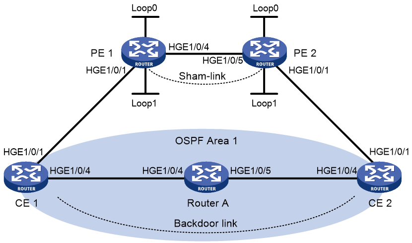
Table 12 Interface and IP address assignment
|
Interface |
IP address |
Device |
Interface |
IP address |
|
|
CE 1 |
HGE1/0/1 |
100.1.1.1/24 |
CE 2 |
HGE1/0/1 |
120.1.1.1/24 |
|
|
HGE1/0/4 |
20.1.1.1/24 |
|
HGE1/0/4 |
30.1.1.2/24 |
|
PE 1 |
Loop0 |
1.1.1.9/32 |
PE 2 |
Loop0 |
2.2.2.9/32 |
|
|
Loop1 |
3.3.3.3/32 |
|
Loop1 |
5.5.5.5/32 |
|
|
HGE1/0/1 |
100.1.1.2/24 |
|
HGE1/0/1 |
120.1.1.2/24 |
|
|
HGE1/0/4 |
10.1.1.1/24 |
|
HGE1/0/5 |
10.1.1.2/24 |
|
Router A |
HGE1/0/5 |
30.1.1.1/24 |
|
|
|
|
|
HGE1/0/4 |
20.1.1.2/24 |
|
|
|
Procedure
1. Configure OSPF on the customer networks:
# Configure conventional OSPF on CE 1, Router A, and CE 2 to advertise addresses of the interfaces (see Table 12). (Details not shown.)
# Set the cost value to 2 for both the link between CE 1 and Router A, and the link between CE 2 and Router A. (Details not shown.)
# Execute the display ip routing-table command to verify that CE 1 and CE 2 have learned the route to each other. (Details not shown.)
2. Configure MPLS L3VPN on the backbone:
# Configure basic MPLS and MPLS LDP on PE 1 to establish LDP LSPs.
<PE1> system-view
[PE1] interface loopback 0
[PE1-LoopBack0] ip address 1.1.1.9 32
[PE1-LoopBack0] quit
[PE1] mpls lsr-id 1.1.1.9
[PE1] mpls ldp
[PE1-ldp] quit
[PE1] interface hundredgige 1/0/4
[PE1-HundredGigE1/0/4] ip address 10.1.1.1 24
[PE1-HundredGigE1/0/4] mpls enable
[PE1-HundredGigE1/0/4] mpls ldp enable
[PE1-HundredGigE1/0/4] quit
# Configure PE 1 to take PE 2 as an MP-IBGP peer.
[PE1] bgp 100
[PE1-bgp-default] peer 2.2.2.9 as-number 100
[PE1-bgp-default] peer 2.2.2.9 connect-interface loopback 0
[PE1-bgp-default] address-family vpnv4
[PE1-bgp-default-vpnv4] peer 2.2.2.9 enable
[PE1-bgp-default-vpnv4] quit
[PE1-bgp-default] quit
# Configure OSPF on PE 1.
[PE1]ospf 1
[PE1-ospf-1]area 0
[PE1-ospf-1-area-0.0.0.0] network 1.1.1.9 0.0.0.0
[PE1-ospf-1-area-0.0.0.0] network 10.1.1.0 0.0.0.255
[PE1-ospf-1-area-0.0.0.0] quit
[PE1-ospf-1] quit
# Configure basic MPLS and MPLS LDP on PE 2 to establish LDP LSPs.
<PE2> system-view
[PE2] interface loopback 0
[PE2-LoopBack0] ip address 2.2.2.9 32
[PE2-LoopBack0] quit
[PE2] mpls lsr-id 2.2.2.9
[PE2] mpls ldp
[PE2-ldp] quit
[PE2] interface hundredgige 1/0/5
[PE2-HundredGigE1/0/5] ip address 10.1.1.2 24
[PE2-HundredGigE1/0/5] mpls enable
[PE2-HundredGigE1/0/5] mpls ldp enable
[PE2-HundredGigE1/0/5] quit
# Configure PE 2 to take PE 1 as an MP-IBGP peer.
[PE2] bgp 100
[PE2-bgp-default] peer 1.1.1.9 as-number 100
[PE2-bgp-default] peer 1.1.1.9 connect-interface loopback 0
[PE2-bgp-default] address-family vpnv4
[PE2-bgp-default-vpnv4] peer 1.1.1.9 enable
[PE2-bgp-default-vpnv4] quit
[PE2-bgp-default] quit
# Configure OSPF on PE 2.
[PE2] ospf 1
[PE2-ospf-1] area 0
[PE2-ospf-1-area-0.0.0.0] network 2.2.2.9 0.0.0.0
[PE2-ospf-1-area-0.0.0.0] network 10.1.1.0 0.0.0.255
[PE2-ospf-1-area-0.0.0.0] quit
[PE2-ospf-1] quit
3. Configure PEs to allow CE access:
# Configure PE 1.
[PE1] ip vpn-instance vpn1
[PE1-vpn-instance-vpn1] route-distinguisher 100:1
[PE1-vpn-instance-vpn1] vpn-target 1:1
[PE1-vpn-instance-vpn1] quit
[PE1] interface hundredgige 1/0/1
[PE1-HundredGigE1/0/1] ip binding vpn-instance vpn1
[PE1-HundredGigE1/0/1] ip address 100.1.1.2 24
[PE1-HundredGigE1/0/1] quit
[PE1] ospf 100 vpn-instance vpn1
[PE1-ospf-100] domain-id 10
[PE1-ospf-100] area 1
[PE1-ospf-100-area-0.0.0.1] network 100.1.1.0 0.0.0.255
[PE1-ospf-100-area-0.0.0.1] quit
[PE1-ospf-100] quit
[PE1] bgp 100
[PE1-bgp-default] ip vpn-instance vpn1
[PE1-bgp-default-vpn1] address-family ipv4 unicast
[PE1-bgp-default-ipv4-vpn1] import-route ospf 100
[PE1-bgp-default-ipv4-vpn1] import-route direct
[PE1-bgp-default-ipv4-vpn1] quit
[PE1-bgp-default-vpn1] quit
[PE1-bgp-default] quit
# Configure PE 2.
[PE2] ip vpn-instance vpn1
[PE2-vpn-instance-vpn1] route-distinguisher 100:2
[PE2-vpn-instance-vpn1] vpn-target 1:1
[PE2-vpn-instance-vpn1] quit
[PE2] interface hundredgige 1/0/1
[PE2-HundredGigE1/0/1] ip binding vpn-instance vpn1
[PE2-HundredGigE1/0/1] ip address 120.1.1.2 24
[PE2-HundredGigE1/0/1] quit
[PE2] ospf 100 vpn-instance vpn1
[PE2-ospf-100] domain-id 10
[PE2-ospf-100] area 1
[PE2-ospf-100-area-0.0.0.1] network 120.1.1.0 0.0.0.255
[PE2-ospf-100-area-0.0.0.1] quit
[PE2-ospf-100] quit
[PE2] bgp 100
[PE2-bgp-default] ip vpn-instance vpn1
[PE2-bgp-default-vpn1] address-family ipv4 unicast
[PE2-bgp-default-ipv4-vpn1] import-route ospf 100
[PE2-bgp-default-ipv4-vpn1] import-route direct
[PE2-bgp-default-ipv4-vpn1] quit
[PE2-bgp-default-vpn1] quit
[PE2-bgp-default] quit
# Execute the display ip routing-table vpn-instance command on the PEs. Verify that the path to the peer CE is along the OSPF route across the customer networks, instead of the BGP route across the backbone. (Details not shown.)
4. Configure a sham link:
# Configure PE 1.
[PE1] interface loopback 1
[PE1-LoopBack1] ip binding vpn-instance vpn1
[PE1-LoopBack1] ip address 3.3.3.3 32
[PE1-LoopBack1] quit
[PE1] ospf 100
[PE1-ospf-100] area 1
[PE1-ospf-100-area-0.0.0.1] sham-link 3.3.3.3 5.5.5.5
[PE1-ospf-100-area-0.0.0.1] quit
[PE1-ospf-100] quit
# Configure PE 2.
[PE2] interface loopback 1
[PE2-LoopBack1] ip binding vpn-instance vpn1
[PE2-LoopBack1] ip address 5.5.5.5 32
[PE2-LoopBack1] quit
[PE2] ospf 100
[PE2-ospf-100] area 1
[PE2-ospf-100-area-0.0.0.1] sham-link 5.5.5.5 3.3.3.3
[PE2-ospf-100-area-0.0.0.1] quit
[PE2-ospf-100] quit
Verifying the configuration
# Execute the display ip routing-table vpn-instance command on the PEs to verify the following results (details not shown):
· The path to the peer CE is now along the BGP route across the backbone.
· A route to the sham link destination address exists.
# Execute the display ip routing-table command on the CEs. Verify that the next hop of the OSPF route to the peer CE is the interface connected to the PE (HundredGigE 1/0/1). This means that VPN traffic to the peer CE is forwarded over the backbone. (Details not shown.)
# Verify that a sham link has been established on PEs, for example, on PE 1.
[PE1] display ospf sham-link
OSPF Process 100 with Router ID 100.1.1.2
Sham link
Area Neighbor ID Source IP Destination IP State Cost
0.0.0.1 120.1.1.2 3.3.3.3 5.5.5.5 P-2-P 1
# Verify that the peer state is Full on PE 1.
[PE1] display ospf sham-link area 1
OSPF Process 100 with Router ID 100.1.1.2
Sham link: 3.3.3.3 --> 5.5.5.5
Neighbor ID: 120.1.1.2 State: Full
Area: 0.0.0.1
Cost: 1 State: P-2-P Type: Sham
Timers: Hello 10, Dead 40, Retransmit 5, Transmit Delay 1
Request list: 0 Retransmit list: 0
Example: Configuring BGP AS number substitution
Network configuration
As shown in Figure 37, CE 1 and CE 2 belong to VPN 1 and are connected to PE 1 and PE 2, respectively. The two CEs have the same AS number, 600.
Configure BGP AS number substitution on the PEs to enable the CEs to communicate with each other.
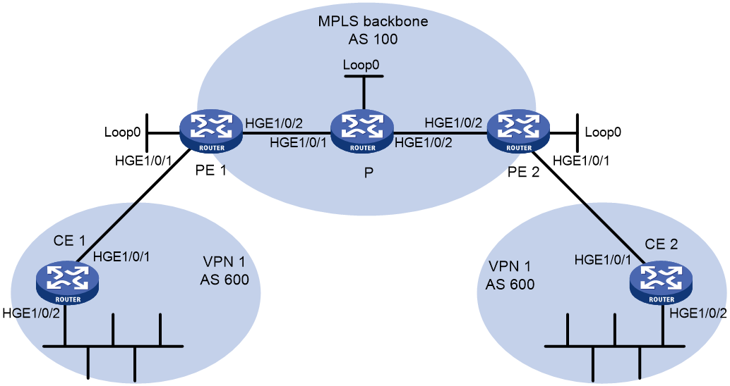
Table 13 Interface and IP address assignment
|
Interface |
IP address |
Device |
Interface |
IP address |
|
|
CE 1 |
HGE1/0/1 |
10.1.1.1/24 |
P |
Loop0 |
2.2.2.9/32 |
|
|
HGE1/0/2 |
100.1.1.1/24 |
|
HGE1/0/1 |
20.1.1.2/24 |
|
PE 1 |
Loop0 |
1.1.1.9/32 |
|
HGE1/0/2 |
30.1.1.1/24 |
|
|
HGE1/0/1 |
10.1.1.2/24 |
PE 2 |
Loop0 |
3.3.3.9/32 |
|
|
HGE1/0/2 |
20.1.1.1/24 |
|
HGE1/0/1 |
10.2.1.2/24 |
|
CE 2 |
HGE1/0/1 |
10.2.1.1/24 |
|
HGE1/0/2 |
30.1.1.2/24 |
|
|
HGE1/0/2 |
200.1.1.1/24 |
|
|
|
Procedure
1. Configure basic MPLS L3VPN:
¡ Configure OSPF on the MPLS backbone to allow the PEs and P device to learn the routes of the loopback interfaces from each other.
¡ Configure basic MPLS and MPLS LDP on the MPLS backbone to establish LDP LSPs.
¡ Establish MP-IBGP peer relationship between the PEs to advertise VPN IPv4 routes.
¡ Configure the VPN instance of VPN 1 on PE 2 to allow CE 2 to access the network.
¡ Configure the VPN instance of VPN 1 on PE 1 to allow CE 1 to access the network.
¡ Configure BGP as the PE-CE routing protocol, and redistribute routes of CEs into PEs.
For more information about basic MPLS L3VPN configurations, see "Example: Configuring basic MPLS L3VPN."
# Execute the display ip routing-table command on CE 2. The output shows that CE 2 has learned the route to network 10.1.1.0/24, where the interface used by CE 1 to access PE 1 resides. However, it has not learned the route to the VPN (100.1.1.0/24) behind CE 1.
<CE2> display ip routing-table
Destinations : 17 Routes : 17
Destination/Mask Proto Pre Cost NextHop Interface
0.0.0.0/32 Direct 0 0 127.0.0.1 InLoop0
10.1.1.0/24 BGP 255 0 10.2.1.2 HGE1/0/1
10.2.1.0/24 Direct 0 0 10.2.1.1 HGE1/0/1
10.2.1.0/32 Direct 0 0 10.2.1.1 HGE1/0/1
10.2.1.1/32 Direct 0 0 127.0.0.1 InLoop0
10.2.1.255/32 Direct 0 0 10.2.1.1 HGE1/0/1
127.0.0.0/8 Direct 0 0 127.0.0.1 InLoop0
127.0.0.0/32 Direct 0 0 127.0.0.1 InLoop0
127.0.0.1/32 Direct 0 0 127.0.0.1 InLoop0
127.255.255.255/32 Direct 0 0 127.0.0.1 InLoop0
200.1.1.0/24 Direct 0 0 200.1.1.1 HGE1/0/2
200.1.1.0/32 Direct 0 0 200.1.1.1 HGE1/0/2
200.1.1.1/32 Direct 0 0 127.0.0.1 InLoop0
200.1.1.255/24 Direct 0 0 200.1.1.1 HGE1/0/2
224.0.0.0/4 Direct 0 0 0.0.0.0 NULL0
224.0.0.0/24 Direct 0 0 0.0.0.0 NULL0
255.255.255.255/32 Direct 0 0 127.0.0.1 InLoop0
# Execute the display ip routing-table command on CE 1 to verify that CE 1 has not learned the route to the VPN behind CE 2. (Details not shown.)
# Execute the display ip routing-table vpn-instance command on the PEs. The output shows the route to the VPN behind the peer CE. This example uses PE 2.
<PE2> display ip routing-table vpn-instance vpn1
Destinations : 15 Routes : 15
Destination/Mask Proto Pre Cost NextHop Interface
0.0.0.0/32 Direct 0 0 127.0.0.1 InLoop0
10.1.1.0/24 BGP 255 0 1.1.1.9 HGE1/0/2
10.2.1.0/24 Direct 0 0 10.2.1.2 HGE1/0/1
10.2.1.0/32 Direct 0 0 10.2.1.2 HGE1/0/1
10.2.1.2/32 Direct 0 0 127.0.0.1 InLoop0
10.2.1.255/32 Direct 0 0 10.2.1.2 HGE1/0/1
100.1.1.0/24 BGP 255 0 1.1.1.9 HGE1/0/2
127.0.0.0/8 Direct 0 0 127.0.0.1 InLoop0
127.0.0.0/32 Direct 0 0 127.0.0.1 InLoop0
127.0.0.1/32 Direct 0 0 127.0.0.1 InLoop0
127.255.255.255/32 Direct 0 0 127.0.0.1 InLoop0
200.1.1.0/24 BGP 255 0 10.2.1.1 HGE1/0/1
224.0.0.0/4 Direct 0 0 0.0.0.0 NULL0
224.0.0.0/24 Direct 0 0 0.0.0.0 NULL0
255.255.255.255/32 Direct 0 0 127.0.0.1 InLoop0
# Enable BGP update packet debugging on PE 2. The output shows that PE 2 advertises the route to 100.1.1.0/24, and the AS_PATH is 100 600.
<PE2> terminal monitor
<PE2> terminal logging level 7
<PE2> debugging bgp update vpn-instance vpn1 10.2.1.1 ipv4
<PE2> refresh bgp all export ipv4 vpn-instance vpn1
*Jun 13 16:12:52:096 2012 PE2 BGP/7/DEBUG:
BGP.vpn1: Send UPDATE to peer 10.2.1.1 for following destinations:
Origin : Incomplete
AS Path : 100 600
Next Hop : 10.2.1.2
100.1.1.0/24,
# Execute the display bgp routing-table ipv4 peer received-routes command on CE 2 to verify that CE 2 has not received the route to 100.1.1.0/24.
<CE2> display bgp routing-table ipv4 peer 10.2.1.2 received-routes
Total number of routes: 2
BGP local router ID is 200.1.1.1
Status codes: * - valid, > - best, d - dampened, h - history,
s - suppressed, S - stale, i - internal, e - external
Origin: i - IGP, e - EGP, ? - incomplete
Network NextHop MED LocPrf PrefVal Path/Ogn
* >e 10.1.1.0/24 10.2.1.2 0 100?
* e 10.2.1.0/24 10.2.1.2 0 0 100?
2. Configure BGP AS number substitution on PE 2.
<PE2> system-view
[PE2] bgp 100
[PE2-bgp-default] ip vpn-instance vpn1
[PE2-bgp-default-vpn1] peer 10.2.1.1 substitute-as
[PE2-bgp-default-vpn1] address-family ipv4 unicast
[PE2-bgp-default-ipv4-vpn1] peer 10.2.1.1 enable
[PE2-bgp-default-ipv4-vpn1] quit
[PE2-bgp-default-vpn1] quit
[PE2-bgp-default] quit
Verifying the configuration
# The output shows that among the routes advertised by PE 2 to CE 2, the AS_PATH of 100.1.1.0/24 has changed from 100 600 to 100 100.
*Jun 13 16:15:59:456 2012 PE2 BGP/7/DEBUG:
BGP.vpn1: Send UPDATE to peer 10.2.1.1 for following destinations:
Origin : Incomplete
AS Path : 100 100
Next Hop : 10.2.1.2
100.1.1.0/24,
# Display again the routing information that CE 2 has received, and the routing table.
<CE2> display bgp routing-table ipv4 peer 10.2.1.2 received-routes
Total number of routes: 3
BGP local router ID is 200.1.1.1
Status codes: * - valid, > - best, d - dampened, h - history,
s - suppressed, S - stale, i - internal, e - external
Origin: i - IGP, e - EGP, ? - incomplete
Network NextHop MED LocPrf PrefVal Path/Ogn
* >e 10.1.1.0/24 10.2.1.2 0 100?
* e 10.2.1.0/24 10.2.1.2 0 0 100?
* >e 100.1.1.0/24 10.2.1.2 0 100 100?
<CE2> display ip routing-table
Destinations : 18 Routes : 18
Destination/Mask Proto Pre Cost NextHop Interface
0.0.0.0/32 Direct 0 0 127.0.0.1 InLoop0
10.1.1.0/24 BGP 255 0 10.2.1.2 HGE1/0/1
10.2.1.0/24 Direct 0 0 10.2.1.1 HGE1/0/1
10.2.1.0/32 Direct 0 0 10.2.1.1 HGE1/0/1
10.2.1.1/32 Direct 0 0 127.0.0.1 InLoop0
10.2.1.255/32 Direct 0 0 10.2.1.1 HGE1/0/1
100.1.1.0/24 BGP 255 0 10.2.1.2 HGE1/0/1
127.0.0.0/8 Direct 0 0 127.0.0.1 InLoop0
127.0.0.0/32 Direct 0 0 127.0.0.1 InLoop0
127.0.0.1/32 Direct 0 0 127.0.0.1 InLoop0
127.255.255.255/32 Direct 0 0 127.0.0.1 InLoop0
200.1.1.0/24 Direct 0 0 200.1.1.1 HGE1/0/2
200.1.1.0/32 Direct 0 0 200.1.1.1 HGE1/0/2
200.1.1.1/32 Direct 0 0 127.0.0.1 InLoop0
200.1.1.255/32 Direct 0 0 200.1.1.1 HGE1/0/2
224.0.0.0/4 Direct 0 0 0.0.0.0 NULL0
224.0.0.0/24 Direct 0 0 0.0.0.0 NULL0
255.255.255.255/32 Direct 0 0 127.0.0.1 InLoop0
# After you also configure BGP AS substitution on PE 1, verify that the interfaces of CE 1 and CE 2 can ping each other. (Details not shown.)
Example: Configuring BGP AS number substitution and SoO attribute
Network configuration
CE 1, CE 2, and CE 3 belong to VPN 1, and are connected to PE1, PE 2, and PE 3, respectively.
CE 1 and CE 2 reside in the same site. CE1, CE2, and CE 3 all use AS number 600.
· To avoid route loss, configure BGP AS number substitution on PEs.
· To avoid routing loops, configure the same SoO attribute on PE 1 and PE 2 for CE 1 and CE 2.
Figure 38 Network diagram
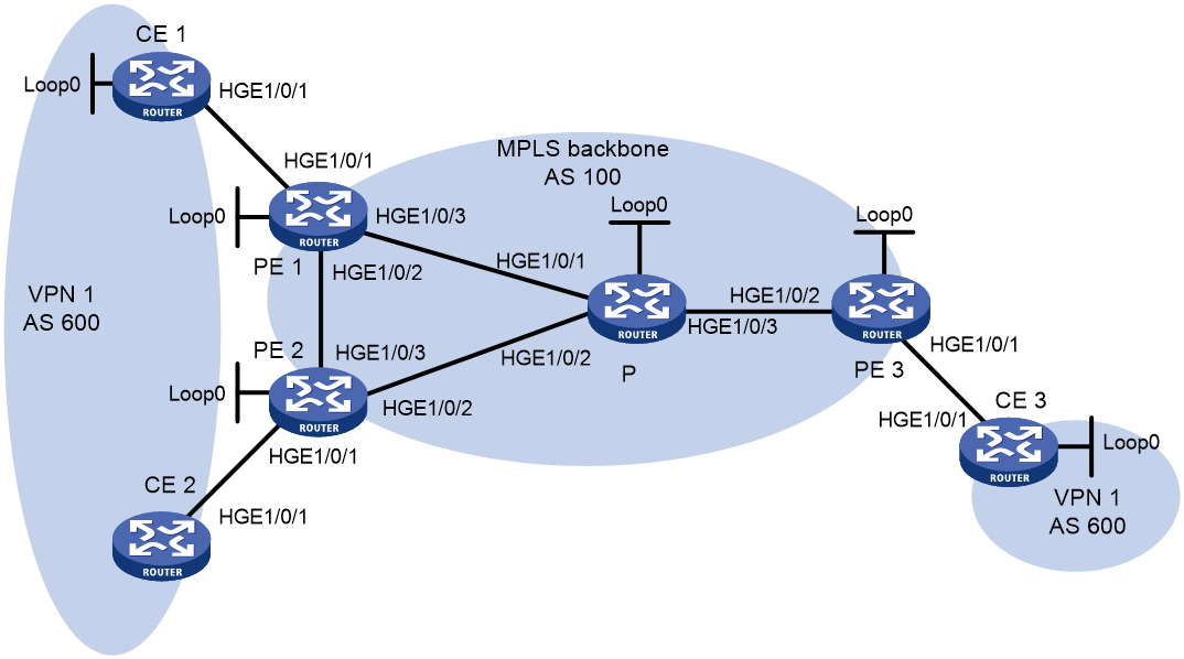
Table 14 Interface and IP address assignment
|
Device |
Interface |
IP address |
Device |
Interface |
IP address |
|
CE 1 |
Loop0 |
100.1.1.1/32 |
CE 3 |
Loop0 |
200.1.1.1 /32 |
|
|
HGE1/0/1 |
10.1.1.1/24 |
|
HGE1/0/1 |
10.3.1.1/24 |
|
CE 2 |
HGE1/0/1 |
10.2.1.1/24 |
PE 2 |
Loop0 |
2.2.2.9/32 |
|
PE 1 |
Loop0 |
1.1.1.9/32 |
|
HGE1/0/1 |
10.2.1.2/24 |
|
|
HGE1/0/1 |
10.1.1.2/24 |
|
HGE1/0/2 |
40.1.1.1/24 |
|
|
HGE1/0/2 |
20.1.1.1/24 |
|
HGE1/0/3 |
20.1.1.2/24 |
|
|
HGE1/0/3 |
30.1.1.1/24 |
P |
Loop0 |
3.3.3.9/32 |
|
PE 3 |
Loop0 |
4.4.4.9/32 |
|
HGE1/0/1 |
30.1.1.2/24 |
|
|
HGE1/0/1 |
10.3.1.2/24 |
|
HGE1/0/2 |
40.1.1.2/24 |
|
|
HGE1/0/2 |
50.1.1.2/24 |
|
HGE1/0/3 |
50.1.1.1/24 |
Procedure
1. Configure basic MPLS L3VPN:
¡ Configure OSPF on the MPLS backbone to allow the PEs and P device to learn the routes of the loopback interfaces from each other.
¡ Configure basic MPLS and MPLS LDP on the MPLS backbone to establish LDP LSPs.
¡ Establish MP-IBGP peer relationship between the PEs to advertise VPN IPv4 routes.
¡ Configure the VPN instance of VPN 1 on PE 1 to allow CE 1 to access the network.
¡ Configure the VPN instance of VPN 1 on PE 2 to allow CE 2 to access the network.
¡ Configure the VPN instance of VPN 1 on PE 3 to allow CE 3 to access the network.
¡ Configure BGP as the PE-CE routing protocol, and redistribute routes of CEs into PEs.
For more information about basic MPLS L3VPN configurations, see "Example: Configuring basic MPLS L3VPN."
2. Configure BGP AS number substitution:
# Configure BGP AS number substitution on PE 1, PE 2, and PE 3. For more information about the configuration, see "Example: Configuring BGP AS number substitution."
# Display routing information on CE 2. The output shows that CE 2 has learned the route for 100.1.1.1/32 from CE 1. A routing loop has occurred because CE 1 and CE 2 reside in the same site.
<CE2> display bgp routing-table ipv4 peer 10.2.1.2 received-routes
Total number of routes: 6
BGP local router ID is 1.1.1.9
Status codes: * - valid, > - best, d - dampened, h - history,
s - suppressed, S - stale, i - internal, e - external
Origin: i - IGP, e - EGP, ? - incomplete
Network NextHop MED LocPrf PrefVal Path/Ogn
* >e 10.1.1.0/24 10.2.1.2 0 100?
* 10.2.1.0/24 10.2.1.2 0 0 100?
* 10.2.1.1/32 10.2.1.2 0 0 100?
* >e 10.3.1.0/24 10.2.1.2 0 100?
* >e 100.1.1.1/32 10.2.1.2 0 100 100?
* >e 200.1.1.1/32 10.2.1.2 0 100 100?
3. Configure BGP SoO attribute:
# On PE 1, configure the SoO attribute as 1:100 for CE 1.
<PE1> system-view
[PE1] bgp 100
[PE1-bgp-default] ip vpn-instance vpn1
[PE1-bgp-default-vpn1] address-family ipv4
[PE1-bgp-default-ipv4-vpn1] peer 10.1.1.1 soo 1:100
# On PE 2, configure the SoO attribute as 1:100 for CE 2.
<PE2> system-view
[PE2] bgp 100
[PE2-bgp-default] ip vpn-instance vpn1
[PE2-bgp-default-vpn1] address-family ipv4
[PE2-bgp-default-ipv4-vpn1] peer 10.2.1.1 soo 1:100
Verifying the configuration
# PE 2 does not advertise routes received from CE 1 to CE 2 because the same SoO attribute has been configured for the CEs. Display the routing table of CE 2. The output shows that the route 100.1.1.1/32 has been removed.
<CE2> display ip routing-table
Destinations : 14 Routes : 14
Destination/Mask Proto Pre Cost NextHop Interface
0.0.0.0/32 Direct 0 0 127.0.0.1 InLoop0
10.2.1.0/24 Direct 0 0 10.2.1.1 HGE1/0/1
10.2.1.0/32 Direct 0 0 10.2.1.1 HGE1/0/1
10.2.1.1/32 Direct 0 0 127.0.0.1 Inloop0
10.2.1.255/32 Direct 0 0 10.2.1.1 HGE1/0/1
10.3.1.0/24 BGP 255 0 10.2.1.2 HGE1/0/1
127.0.0.0/8 Direct 0 0 127.0.0.1 InLoop0
127.0.0.0/32 Direct 0 0 127.0.0.1 InLoop0
127.0.0.1/32 Direct 0 0 127.0.0.1 InLoop0
127.255.255.255/32 Direct 0 0 127.0.0.1 InLoop0
200.1.1.1/32 BGP 255 0 10.2.1.2 HGE1/0/1
224.0.0.0/4 Direct 0 0 0.0.0.0 NULL0
224.0.0.0/24 Direct 0 0 0.0.0.0 NULL0
255.255.255.255/32 Direct 0 0 127.0.0.1 InLoop0
Example: Configuring MPLS L3VPN FRR through VPNv4 route backup for a VPNv4 route
Network configuration
CE 1 and CE 2 belong to VPN 1.
Configure EBGP between CEs and PEs to exchange VPN routes.
Configure OSPF to ensure connectivity between PEs, and configure MP-IBGP to exchange VPNv4 routing information between PEs.
Configure MPLS L3VPN FRR on PE 1 to achieve the following purposes:
· When the link PE 1—PE 2 operates correctly, traffic from CE 1 to CE 2 goes through the path CE 1—PE 1—PE 2—CE 2.
· When BFD detects that the LSP between PE 1 and PE 2 fails, traffic from CE 1 to CE 2 goes through the path CE 1—PE 1—PE 3—CE 2.
Figure 39 Network diagram
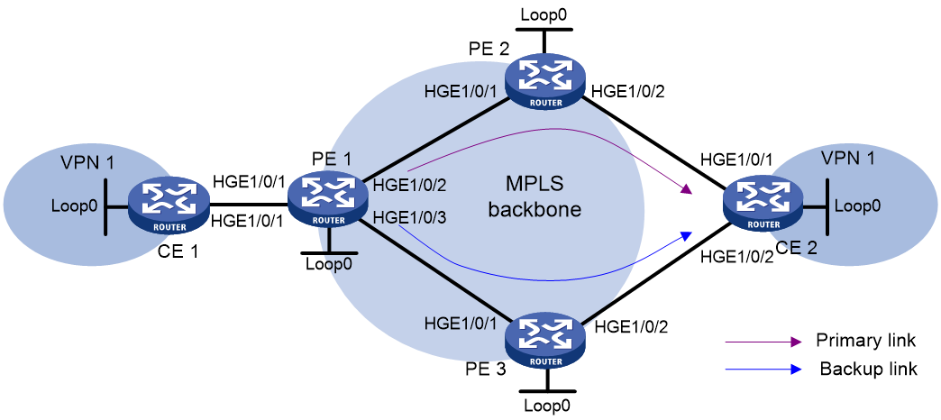
Table 15 Interface and IP address assignment
|
Device |
Interface |
IP address |
Device |
Interface |
IP address |
|
CE 1 |
Loop0 |
5.5.5.5/32 |
PE 1 |
Loop0 |
1.1.1.1/32 |
|
HGE1/0/1 |
10.2.1.1/24 |
HGE1/0/1 |
10.2.1.2/24 |
||
|
PE 2 |
Loop0 |
2.2.2.2/32 |
HGE1/0/2 |
172.1.1.1/24 |
|
|
HGE1/0/1 |
172.1.1.2/24 |
HGE1/0/3 |
172.2.1.1/24 |
||
|
HGE1/0/2 |
10.1.1.2/24 |
CE 2 |
Loop0 |
4.4.4.4/32 |
|
|
PE 3 |
Loop0 |
3.3.3.3/32 |
HGE1/0/1 |
10.1.1.1/24 |
|
|
HGE1/0/1 |
172.2.1.3/24 |
HGE1/0/2 |
10.3.1.1/24 |
||
|
HGE1/0/2 |
10.3.1.2/24 |
Procedure
1. Configure IP addresses and masks for interfaces as shown in Table 15, and configure BGP and MPLS L3VPN. (Details not shown.)
For more information about configuring basic MPLS L3VPN, see "Example: Configuring basic MPLS L3VPN."
2. Configure MPLS L3VPN FRR on PE 1:
# Configure BFD to test the connectivity of the LSP to 2.2.2.2/32.
<PE1> system-view
[PE1] mpls bfd enable
[PE1] mpls bfd 2.2.2.2 32
# Create routing policy frr, and specify the backup next hop as 3.3.3.3 for the route to 4.4.4.4/32.
[PE1] ip prefix-list abc index 10 permit 4.4.4.4 32
[PE1] route-policy frr permit node 10
[PE1-route-policy-frr-10] if-match ip address prefix-list abc
[PE1-route-policy-frr-10] apply fast-reroute backup-nexthop 3.3.3.3
[PE1-route-policy-frr-10] quit
# Configure FRR for VPN instance vpn1 to use routing policy frr.
[PE1] bgp 100
[PE1-bgp-default] ip vpn-instance vpn1
[PE1-bgp-default-vpn1] address-family ipv4 unicast
[PE1-bgp-default-ipv4-vpn1] fast-reroute route-policy frr
[PE1-bgp-default-ipv4-vpn1] quit
[PE1-bgp-default-vpn1] quit
# Specify the preferred value as 100 for routes received from PE 2. This value is greater than the preferred value (0) for routes from PE 3, so PE 1 prefers the routes from PE 2.
[PE1-bgp-default] address-family vpnv4
[PE1-bgp-default-vpnv4] peer 2.2.2.2 preferred-value 100
[PE1-bgp-default-vpnv4] quit
[PE1-bgp-default] quit
3. Enable MPLS BFD on PE 2.
<PE2> system-view
[PE2] mpls bfd enable
Verifying the configuration
# Display detailed information about the route to 4.4.4.4/32 on PE 1. The output shows the backup next hop for the route.
[PE1] display ip routing-table vpn-instance vpn1 4.4.4.4 32 verbose
Summary Count : 1
Destination: 4.4.4.4/32
Protocol: BGP
Process ID: 0
SubProtID: 0x1 Age: 00h00m03s
Cost: 0 Preference: 255
IpPre: N/A QosLocalID: N/A
Tag: 0 State: Active Adv
OrigTblID: 0x0 OrigVrf: default-vrf
TableID: 0x102 OrigAs: 300
NibID: 0x15000002 LastAs: 300
AttrID: 0x2 Neighbor: 2.2.2.2
Flags: 0x110060 OrigNextHop: 2.2.2.2
Label: 1146 RealNextHop: 172.1.1.2
BkLabel: 1275 BkNextHop: 172.2.1.3
Tunnel ID: Invalid Interface: HGE1/0/2
BkTunnel ID: Invalid BkInterface: HGE1/0/3
FtnIndex: 0x0 TrafficIndex: N/A
Connector: N/A PathID: 0x0
VpnPeerId: N/A Dscp: N/A
Exp: N/A
Example: Configuring MPLS L3VPN FRR through VPNv4 route backup for an IPv4 route
Network configuration
CE 1 and CE 2 belong to VPN 1.
Configure EBGP between CEs and PEs to exchange VPN routes.
Configure OSPF to ensure connectivity between PEs, and configure MP-IBGP to exchange VPNv4 routing information between PEs.
Configure MPLS L3VPN FRR on PE 2 to achieve the following purposes:
· When the link PE 2—CE 2 operates correctly, traffic from CE 1 to CE 2 goes through the path CE 1—PE 1—PE 2—CE 2.
· When BFD detects that the link between PE 2 and CE 2 fails, traffic from CE 1 to CE 2 goes through the path CE 1—PE 1—PE 2—PE 3—CE 2.
Figure 40 Network diagram
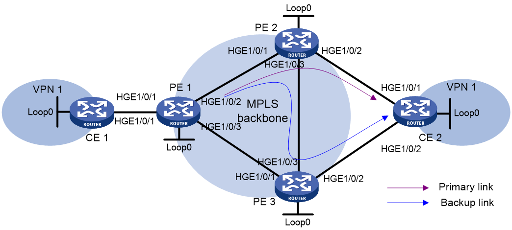
Table 16 Interface and IP address assignment
|
Device |
Interface |
IP address |
Device |
Interface |
IP address |
|
CE 1 |
Loop0 |
5.5.5.5/32 |
PE 2 |
Loop0 |
2.2.2.2/32 |
|
HGE1/0/1 |
10.2.1.1/24 |
HGE1/0/1 |
172.1.1.2/24 |
||
|
PE 1 |
Loop0 |
1.1.1.1/32 |
HGE1/0/2 |
10.1.1.2/24 |
|
|
HGE1/0/1 |
10.2.1.2/24 |
HGE1/0/3 |
172.3.1.2/24 |
||
|
HGE1/0/2 |
172.1.1.1/24 |
PE 3 |
Loop0 |
3.3.3.3/32 |
|
|
HGE1/0/3 |
172.2.1.1/24 |
HGE1/0/1 |
172.2.1.3/24 |
||
|
CE 2 |
Loop0 |
4.4.4.4/32 |
HGE1/0/2 |
10.3.1.2/24 |
|
|
HGE1/0/1 |
10.1.1.1/24 |
HGE1/0/3 |
172.3.1.3/24 |
||
|
HGE1/0/2 |
10.3.1.1/24 |
Procedure
1. Configure IP addresses and masks for interfaces as shown in Table 16, and configure BGP and MPLS L3VPN. (Details not shown.)
For more information about configuring basic MPLS L3VPN, see "Example: Configuring basic MPLS L3VPN."
2. Configure MPLS L3VPN FRR on PE 2:
# Configure the source IP address of BFD echo packets as 12.1.1.1.
<PE2> system-view
[PE2] bfd echo-source-ip 12.1.1.1
# Create routing policy frr, and specify the backup next hop as 3.3.3.3 for the route to 4.4.4.4/32.
[PE2] ip prefix-list abc index 10 permit 4.4.4.4 32
[PE2] route-policy frr permit node 10
[PE2-route-policy-frr-10] if-match ip address prefix-list abc
[PE2-route-policy-frr-10] apply fast-reroute backup-nexthop 3.3.3.3
[PE2-route-policy-frr-10] quit
# Use echo-mode BFD to detect the primary route connectivity.
[PE2] bgp 100
[PE2-bgp-default] primary-path-detect bfd echo
# Configure FRR for VPN instance vpn1 to use routing policy frr.
[PE2-bgp-default] ip vpn-instance vpn1
[PE2-bgp-default-vpn1] address-family ipv4 unicast
[PE2-bgp-default-ipv4-vpn1] fast-reroute route-policy frr
# Specify the preferred value as 200 for BGP routes received from CE 2. This value is greater than the preferred value (0) for routes from PE 3, so PE 2 prefers the routes from CE 2.
[PE2-bgp-default-ipv4-vpn1] peer 10.1.1.1 preferred-value 200
[PE2-bgp-default-vpn1] quit
[PE2-bgp-default] quit
Verifying the configuration
# Display detailed information about the route to 4.4.4.4/32 on PE 2. The output shows the backup next hop for the route.
[PE2] display ip routing-table vpn-instance vpn1 4.4.4.4 32 verbose
Summary Count : 1
Destination: 4.4.4.4/32
Protocol: BGP
Process ID: 0
SubProtID: 0x2 Age: 01h54m24s
Cost: 0 Preference: 10
IpPre: N/A QosLocalID: N/A
Tag: 0 State: Active Adv
OrigTblID: 0x0 OrigVrf: vpn1
TableID: 0x102 OrigAs: 300
NibID: 0x15000002 LastAs: 300
AttrID: 0x0 Neighbor: 10.1.1.1
Flags: 0x10060 OrigNextHop: 10.1.1.1
Label: NULL RealNextHop: 10.1.1.1
BkLabel: 1275 BkNextHop: 172.3.1.3
Tunnel ID: Invalid Interface: HGE1/0/2
BkTunnel ID: 0x409 BkInterface: HGE1/0/3
FtnIndex: 0x0 TrafficIndex: N/A
Connector: N/A
Example: Configuring MPLS L3VPN FRR through IPv4 route backup for a VPNv4 route
Network configuration
CE 1 and CE 2 belong to VPN 1.
Configure EBGP between CEs and PEs to exchange VPN routes.
Configure OSPF to ensure connectivity between PEs, and configure MP-IBGP to exchange VPNv4 routing information between PEs.
Configure MPLS L3VPN FRR on PE 1 to achieve the following purposes:
· When the link PE 1—PE 2 operates correctly, traffic from CE 1 to CE 2 goes through the path CE 1—PE 1—PE 2—CE 2.
· When BFD detects that the link between PE 1 and PE 2 fails, traffic from CE 1 to CE 2 goes through the path CE 1—PE 1—CE 2.
Figure 41 Network diagram
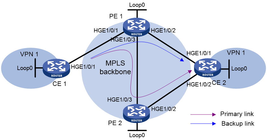
Table 17 Interface and IP address assignment
|
Device |
Interface |
IP address |
Device |
Interface |
IP address |
|
CE 1 |
Loop0 |
5.5.5.5/32 |
CE 2 |
Loop0 |
4.4.4.4/32 |
|
HGE1/0/1 |
10.2.1.1/24 |
HGE1/0/1 |
10.1.1.1/24 |
||
|
PE 1 |
Loop0 |
1.1.1.1/32 |
HGE1/0/2 |
10.3.1.1/24 |
|
|
HGE1/0/1 |
10.2.1.2/24 |
PE 2 |
Loop0 |
2.2.2.2/32 |
|
|
HGE1/0/2 |
10.1.1.2/24 |
HGE1/0/2 |
10.3.1.2/24 |
||
|
HGE1/0/3 |
172.2.1.1/24 |
HGE1/0/3 |
172.2.1.2/24 |
Procedure
1. Configure IP addresses and masks for interfaces as shown in Table 17, and configure BGP and MPLS L3VPN. (Details not shown.)
For more information about configuring basic MPLS L3VPN, see "Example: Configuring basic MPLS L3VPN."
2. Configure MPLS L3VPN FRR on PE 1:
# Configure BFD to test the connectivity of the LSP to 2.2.2.2/32.
<PE1> system-view
[PE1] mpls bfd enable
[PE1] mpls bfd 2.2.2.2 32
# Create routing policy frr, and specify the backup next hop as 10.1.1.1 for the route to 4.4.4.4/32.
[PE1] ip prefix-list abc index 10 permit 4.4.4.4 32
[PE1] route-policy frr permit node 10
[PE1-route-policy-frr-10] if-match ip address prefix-list abc
[PE1-route-policy-frr-10] apply fast-reroute backup-nexthop 10.1.1.1
[PE1-route-policy-frr-10] quit
# Configure FRR for VPN instance vpn1 to use routing policy frr.
[PE1] bgp 100
[PE1-bgp-default] ip vpn-instance vpn1
[PE1-bgp-default-vpn1] address-family ipv4 unicast
[PE1-bgp-default-ipv4-vpn1] fast-reroute route-policy frr
[PE1-bgp-default-ipv4-vpn1] quit
[PE1-bgp-default-vpn1] quit
# Specify the preferred value as 200 for BGP VPNv4 routes received from PE 2. This value is greater than the preferred value (0) for IPv4 unicast routes from CE 2, so PE 1 prefers the routes from PE 2.
[PE1-bgp-default] address-family vpnv4
[PE1-bgp-default-vpnv4] peer 2.2.2.2 preferred-value 200
[PE1-bgp-default-vpnv4] quit
[PE1-bgp-default] quit
3. Enable MPLS BFD on PE 2.
<PE2> system-view
[PE2] mpls bfd enable
Verifying the configuration
# Display detailed information about the route to 4.4.4.4/32 on PE 1. The output shows the backup next hop for the route.
[PE1] display ip routing-table vpn-instance vpn1 4.4.4.4 32 verbose
Summary Count : 1
Destination: 4.4.4.4/32
Protocol: BGP
Process ID: 0
SubProtID: 0x1 Age: 00h00m04s
Cost: 0 Preference: 255
IpPre: N/A QosLocalID: N/A
Tag: 0 State: Active Adv
OrigTblID: 0x0 OrigVrf: default-vrf
TableID: 0x102 OrigAs: 300
NibID: 0x15000004 LastAs: 300
AttrID: 0x1 Neighbor: 2.2.2.2
Flags: 0x110060 OrigNextHop: 2.2.2.2
Label: 1275 RealNextHop: 172.2.1.2
BkLabel: NULL BkNextHop: 10.1.1.1
Tunnel ID: 0x409 Interface: HGE1/0/3
BkTunnel ID: Invalid BkInterface: HGE1/0/2
FtnIndex: 0x0 TrafficIndex: N/A
Connector: N/A PathID: 0x0
VpnPeerId: N/A Dscp: N/A
Exp: N/A
