- Table of Contents
- Related Documents
-
| Title | Size | Download |
|---|---|---|
| 04-Telemetry stream configuration | 79.59 KB |
Contents
Restrictions and guidelines: Telemetry stream configuration
Configuring basic telemetry stream functions
Configuring telemetry stream timestamping
Verifying and maintaining telemetry stream
Verifying the configuration and running status for ACLs
Verifying telemetry stream and sampler configuration
Configuring telemetry stream
About telemetry stream
Telemetry stream is a network monitoring technology used to collect data from devices. It continuously streams data to a collector.
Telemetry stream supports collecting the input interface, output interface and timestamp of traffic.
How telemetry stream works
Telemetry stream works as follows:
1. Telemetry stream samples a matching packet on the input interface and copies it to the telemetry stream processor in the device. The telemetry stream processor adds the input interface information to the packet.
2. The telemetry stream processor encapsulates the packet and routes it to the collector.
The collector can calculate the path and delay information according to the collected data from multiple nodes.
Telemetry stream timestamping
With this function enabled, the device carries the timestamp in its packets sent to the collector. The collector can calculate the delay introduced when a node forwards packets. Additionally, the collector can use the timestamp information collected from multiple nodes to calculate the delay introduced when packets are forwarded along the path.
Restrictions and guidelines: Telemetry stream configuration
The collected data is encapsulated in sFlow packets. The sFlow packet does not include the Extended Switch Data or Extended Router Data field, and the value of the sample pool field is fixed.
Prerequisites
Configure routing to make sure the devices can reach each other.
Configuring basic telemetry stream functions
About this task
The device samples a matching packet on the input interface and copies it to the telemetry stream processor in the device. The telemetry stream processor adds the input and output interface information to the packet, encapsulates it, and routes it to the collector.
Too many original packets will overwhelm the Telemetry processor and even cause it to drop packets. To address this problem, you can use an ACL or sampler on the input interface to reduce the packets sent to the collector. Only packets matching a permit ACL rule or sampled packets are sent to the collector.
If the data portion of original packets is large, you can enable the truncation function to save the link bandwidth consumed between the device and the collector and reduce the parsing load of the collector. The truncation function truncates the packets before sending them to the collector. The truncated packets retain complete input interface, output interface, and timestamp information.
Procedure
a. Enter system view.
system-view
b. Specify a device ID.
telemetry stream device-id address
By default, no device ID is specified.
2. Configure addressing parameters to encapsulate in the packets sent to the collector.
telemetry stream collector source source-address destination destination-address source-port source-port destination-port destination-port [ vpn-instance vpn-instance-name ] [ truncation ]
By default, no addressing parameters are configured.
As a best practice, specify the truncation keyword when you execute this command. If you do not specify the truncation keyword, telemetry stream might fail to collect data about packets when the packet length approaches the interface MTU.
3. Configure a telemetry stream action on the input interface.
a. Enter interface view.
interface interface-type interface-number
b. Configure a telemetry stream action on the interface.
telemetry stream action action-id [ acl [ ipv6 | mac | user-defined ] { acl-number | name acl-name } | sampler sampler-name ] *
By default, no telemetry stream action is configured.
To collect data about MPLS packets, you must specify a Layer 2 ACL that matches packets with the link layer protocol as 8847.
c. Return to system view.
quit
For information about ACLs, see ACL and QoS Configuration Guide.
For information about samplers, see Network Management and Monitoring Configuration Guide.
4. Enable telemetry stream.
telemetry stream enable
By default, telemetry stream is enabled.
Configuring telemetry stream timestamping
About this task
This feature allows the device to add the timestamp information when a packet enters and leaves it.
Procedure
Enable telemetry stream timestamping.
telemetry stream timestamp enable
By default, telemetry stream timestamping is disabled.
Verifying and maintaining telemetry stream
Verifying the configuration and running status for ACLs
To verify the ACL configuration and running status, perform the following command in any view:
display acl [ ipv6 | mac | user-defined ] { acl-number | all | name acl-name }
For more information about this command, see ACL and QoS Command Reference.
Verifying telemetry stream and sampler configuration
Perform display tasks in any view.
· Display sampler configuration.
For more information about the display sampler command, see Network Management and Monitoring Command Reference.
· Display telemetry stream r configuration.
Telemetry stream configuration examples
Example: Configuring telemetry stream
Network configuration
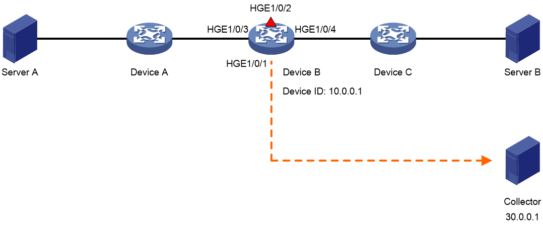
As shown in Figure 1, configure telemetry stream on Device B for the collector to calculate the delay when packets are forwarded by Device B.
Prerequisites
|
|
IMPORTANT: By default, interfaces on the device are disabled (in ADM or Administratively Down state). To have an interface operate, you must use the undo shutdown command to enable that interface. |
Assign IP addresses to interfaces and configure routing protocols. (Details not shown.)
Procedure
# Specify 10.0.0.1 as the device ID.
<DeviceB> system-view
[DeviceB] telemetry stream device-id 10.0.0.1
# Configure addressing parameters to encapsulate in telemetry stream packets sent to the collector.
[DeviceB] telemetry stream collector source 20.0.0.2 destination 30.0.0.1 source-port 12 destination-port 14
# Enable telemetry stream timestamping.
[DeviceB] telemetry stream timestamp enable
# Create sampler samp in random sampling mode, and set the sampling rate to 8. One packet from 256 (2 to the 8th power) packets is selected.
[DeviceB] sampler samp mode random packet-interval n-power 8
# Create IPv4 basic ACL 2000, and configure a rule to match packets with source IP address 192.168.1.2.
[DeviceB] acl basic 2000
[DeviceB-acl-ipv4-basic-2000] rule permit source 192.168.1.2 0
[DeviceB-acl-ipv4-basic-2000] quit
# Configure telemetry stream action 1 to use ACL 2000 and sampler samp on HundredGigE 1/0/1.
[DeviceB] interface hundredgige 1/0/1
[DeviceB-HundredGigE1/0/1] telemetry stream action 1 acl 2000 sampler samp
[DeviceB-HundredGigE1/0/1] quit
# Enable telemetry stream.
[DeviceB] telemetry stream enable
Verifying the configuration
# Display the telemetry stream configuration on Device B.
[DeviceB] display telemetry stream
Telemetry stream status : Enabled
Telemetry stream timestamp status: Enabled
Telemetry stream device-id : 10.0.0.1
Telemetry stream action:
HundredGigE1/0/1:
Telemetry stream action 1:
ACL : 2000
Sampler: samp
Telemetry stream collector:
Source IP : 20.0.0.2
Destination IP : 30.0.0.1
Source port : 12
Destination port: 14
