- Table of Contents
- Related Documents
-
| Title | Size | Download |
|---|---|---|
| 05-EVPN-DCI configuration | 439.64 KB |
Contents
Restrictions and guidelines: EVPN-DCI configuration
Configuring route reorigination on EDs
Enabling route nexthop replacement and route router MAC replacement
Enabling an ED to replace the L3 VXLAN ID, RD, route targets of BGP EVPN routes
Suppressing BGP EVPN route advertisement
Configuring the BGP EVPN address family and the BGP VPNv4 or VPNv6 address family to exchange routes
Enabling BGP VPNv4 or VPNv6 route advertisement for the BGP EVPN address family
Enabling BGP EVPN route advertisement for the BGP VPNv4 or VPNv6 address family
Configuring EVPN-DCI dual-homing
EVPN-DCI configuration examples
Example: Configuring a basic EVPN-DCI network
Example: Configuring EVPN-DCI intermediate VXLAN mapping
Example: Configuring EVPN-DCI IPv4 Layer 3 communication
Example: Configuring EVPN-DCI dual-homing
Example: Configuring EVPN-DCI M-LAG
Configuring EVPN-DCI
About EVPN-DCI
EVPN data center interconnect (EVPN-DCI) uses VXLAN-DCI tunnels to provide connectivity for data centers over an IP transport network.
EVPN-DCI network model
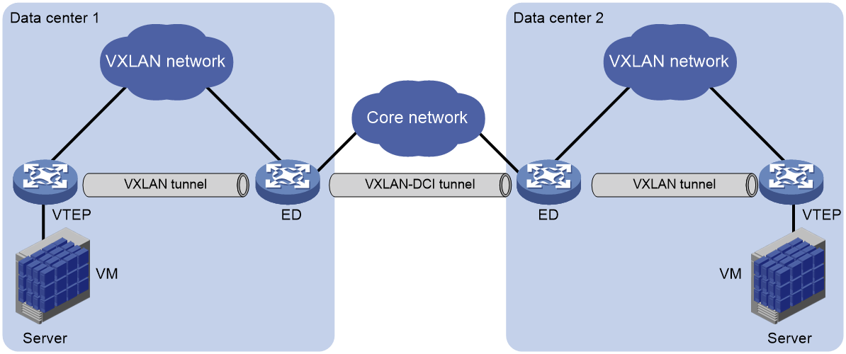
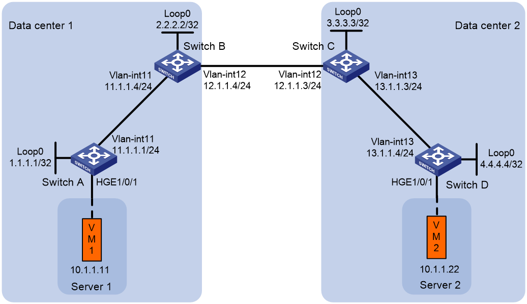
As shown in Figure 1, the EVPN-DCI network contains VTEPs and edge devices (EDs) located at the edge of the transport network. A VXLAN tunnel is established between a VTEP and an ED, and a VXLAN-DCI tunnel is established between two EDs. VXLAN-DCI tunnels use VXLAN encapsulation. Each ED de-encapsulates incoming VXLAN packets and re-encapsulates them based on the destination before forwarding the packets through a VXLAN or VXLAN-DCI tunnel.
Figure 1 EVPN-DCI network model
Working mechanisms
In an EVPN-DCI network, BGP EVPN peer relationships are established between EDs and between EDs and VTEPs. When advertising routes to a VTEP or another ED, an ED replaces the routes' nexthop IP address and router MAC address with its IP address and router MAC address.
In an EVPN-DCI network, a VTEP and an ED use a VXLAN tunnel to send traffic, and two EDs use a VXLAN-DCI tunnel to send traffic. An ED de-encapsulates incoming VXLAN packets and re-encapsulates them before forwarding the packets through a VXLAN or VXLAN-DCI tunnel.
EVPN-DCI dual-homing
As shown in Figure 2, EVPN-DCI dual-homing allows you to deploy two EDs at a data center for high availability and load sharing. To virtualize the redundant EDs into one device, a virtual ED address is configured on them. The redundant EDs use the virtual ED address to establish tunnels with VTEPs and remote EDs.
Figure 2 EVPN-DCI dual-homing
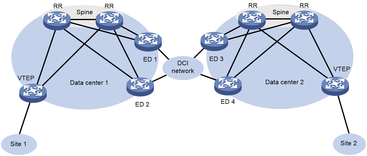
The redundant EDs use their respective IP addresses as the BGP peer addresses to establish BGP EVPN neighbor relationships with VTEPs and remote EDs. The VTEPs and remote EDs send traffic destined for the virtual ED address to both of the redundant EDs through the ECMP routes provided by the underlay network.
The redundant EDs communicate with remote data centers through the transport network. Devices in the dual-homed data center are unaware of the transport network. When the transport-side link fails on one of the redundant EDs, traffic destined for remote data centers is still sent to that ED. To resolve this issue, Monitor Link is used together with EVPN-DCI dual-homing.
On each redundant ED, the transport-facing physical interface is associated with the following loopback interfaces: The loopback interface that provides the IP address used for establishing BGP EVPN neighbor relationships and the loopback interface that provides the virtual ED address. If the transport-side link fails on a redundant ED, the loopback interfaces are placed in down state, and all traffic is forwarded by the other redundant ED. For more information about Monitor Link, see High Availability Configuration Guide.
For link redundancy, deploy multiple RRs on the spine nodes in a data center, and connect each redundant ED to the transport network through multiple links.
EVPN-DCI M-LAG
|
|
IMPORTANT: To use this feature, make sure the site network and the underlay network are both IPv4 networks or both IPv6 networks. |
As shown in Figure 3, you can use M-LAG to virtualize two physical EDs of a data center into a virtual ED to prevent single points of failure from interrupting traffic. For more information about M-LAG, see Layer 2—LAN Switching Configuration Guide.
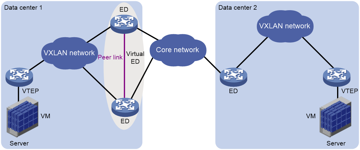
EVPN-DCI M-LAG uses the following mechanisms:
· VM reachability information synchronization—To ensure VM reachability information consistency in the M-LAG system, the member EDs synchronize MAC address entries and ARP or ND information with each other over the peer link. The peer link can only be an Ethernet aggregate link.
· Virtual ED address—The member EDs use a virtual ED address to set up VXLAN tunnels or VXLAN-DCI tunnels with VTEPs or remote EDs.
· Independent BGP neighbor relationship establishment—The member EDs use different BGP peer addresses to establish neighbor relationships with remote devices. For load sharing and link redundancy, a neighbor sends traffic destined for the virtual ED address to both of the member EDs through ECMP routes of the underlay network.
The member EDs in an M-LAG system communicate with remote data centers through the transport network. Devices in the dual-homed data center are unaware of the transport network. When the transport-side link fails on one of the member EDs, traffic destined for remote data centers is still sent to that ED. To resolve this issue, Monitor Link is used together with EVPN-DCI M-LAG.
On each member ED, the transport-facing physical interface is associated with the following loopback interfaces: The loopback interface that provides the IP address used for establishing BGP EVPN neighbor relationships and the loopback interface that provides the virtual ED address. If the transport-side link fails on a member ED, the loopback interfaces are placed in down state, and all traffic is forwarded by the other member ED. For more information about Monitor Link, see High Availability Configuration Guide.
Restrictions and guidelines: EVPN-DCI configuration
On an ED, make sure the VSI interfaces configured with L3 VXLAN IDs use the same MAC address. To modify the MAC address of a VSI interface, use the mac-address command.
EVPN-DCI tasks at a glance
To configure EVPN-DCI, perform the following tasks on EDs:
1. Configuring route reorigination on EDs
¡ Enabling route nexthop replacement and route router MAC replacement
¡ Enabling an ED to replace the L3 VXLAN ID, RD, route targets of BGP EVPN routes
2. (Optional.) Suppressing BGP EVPN route advertisement
To reduce the number of BGP EVPN routes on EDs of an EVPN-DCI network, suppress the advertisement of specific BGP EVPN routes on the EDs.
3. (Optional.) Configuring VXLAN mapping
Perform this task to provide Layer 2 connectivity for a tenant subnet that uses different VXLAN IDs in multiple data centers.
4. Configuring the BGP EVPN address family and the BGP VPNv4 or VPNv6 address family to exchange routes
You must perform this task if data centers are interconnected through an MPLS L3VPN network.
5. (Optional.) Configuring EVPN-DCI dual-homing
6. (Optional.) Configuring EVPN-DCI M-LAG
Prerequisites for EVPN-DCI
Before you configure EVPN-DCI, complete basic EVPN configuration for each data center. For more information about basic EVPN configuration, see "Configuring basic EVPN features."
Configuring route reorigination on EDs
Enabling route nexthop replacement and route router MAC replacement
Restrictions and guidelines
In an EVPN-DCI network, EDs automatically set up VXLAN-DCI tunnels based on EVPN routes to interconnect data centers.
If the dci keyword is specified in the peer router-mac-local command, EDs set up VXLAN-DCI tunnels. If this keyword is not specified, EDs set up VXLAN tunnels.
Procedure
1. Enter system view.
system-view
2. Configure a global router ID.
router id router-id
By default, no global router ID is configured.
3. Enable a BGP instance and enter BGP instance view.
bgp as-number [ instance instance-name ]
By default, BGP is disabled, and no BGP instances exist.
4. Specify local VTEPs and remote EDs as BGP peers.
peer { group-name | ipv4-address [ mask-length ] | ipv6-address [ prefix-length ] } as-number as-number
5. Create the BGP EVPN address family and enter BGP EVPN address family view.
address-family l2vpn evpn
6. Enable BGP to exchange BGP EVPN routes with a peer or peer group.
peer { group-name | ipv4-address [ mask-length ] | ipv6-address [ prefix-length ] } enable
By default, BGP does not exchange BGP EVPN routes with peers.
7. Set the local router as the next hop for routes advertised to a peer or peer group.
peer { group-name | ipv4-address [ mask-length ]| ipv6-address [ prefix-length ] } next-hop-local
The default settings for this command are as follows:
¡ BGP sets the local router as the next hop for all routes advertised to an EBGP peer or peer group.
¡ BGP does not modify the next hop for EBGP routes advertised to an IBGP peer or peer group.
The peers specified in this task must be VTEPs in the local data center.
8. Enable route router MAC replacement for a peer or peer group.
peer { group-name | ipv4-address [ mask-length ] | ipv6-address [ prefix-length ] } router-mac-local [ dci ]
By default, the device does not modify the router MAC address of routes before advertising the routes.
This command enables the device to use its router MAC address to replace the router MAC address of routes received from and advertised to a peer or peer group.
The peers specified in this task must be remote EDs.
To set up VXLAN-DCI tunnels with a peer or peer group, specify the dci keyword. To set up VXLAN tunnels with a peer or peer group, do not specify this keyword.
Enabling an ED to replace the L3 VXLAN ID, RD, route targets of BGP EVPN routes
About this task
In an EVPN-DCI network, use this feature to hide the L3 VXLAN IDs of data centers or enable communication between data centers that use different L3 VXLAN IDs or route targets.
After you enable this feature on an ED, the ED performs the following operations after receiving BGP EVPN routes:
1. Matches the route targets of the routes with the import route targets of local VPN instances.
2. Replaces the L3 VXLAN ID, RD, and route targets of the routes with those of the matching local VPN instance.
3. Advertises the routes to a VTEP or remote ED.
After you execute the peer re-originated command, the ED advertises only reoriginated BGP EVPN routes. For the ED to advertise both original and reoriginated BGP EVPN routes, execute the peer advertise original-route command.
An ED configured with the peer re-originated and peer advertise original-route commands advertises both original and reoriginated BGP EVPN routes. For the ED to advertise only original BGP EVPN routes, execute the peer suppress re-originated command on the ED.
Restrictions and guidelines
If the RD of a received BGP EVPN route is identical to the RD of the matching local VPN instance, an ED does not replace the L3 VXLAN ID of the route or reoriginate the route. As a result, the ED does not advertise the route. As a best practice, assign unique RDs to VPN instances on different EVPN gateways and EDs when you use this command.
Procedure
1. Enter system view.
system-view
2. Enter BGP instance view.
bgp as-number [ instance instance-name ]
3. Enter BGP EVPN address family view.
address-family l2vpn evpn
4. Replace the L3 VXLAN ID and RD of received BGP EVPN routes.
peer { group-name | ipv4-address [ mask-length ] | ipv6-address [ prefix-length ] } re-originated [ imet | ip-prefix | mac-ip ] [ replace-rt ]
By default, the device does not modify the L3 VXLAN ID or RD of the BGP EVPN routes that are received from peers or peer groups.
5. (Optional.) Enable the device to advertise original BGP EVPN routes together with the reoriginated BGP EVPN routes after the peer re-originated command is executed.
peer { group-name | ipv4-address [ mask-length ] | ipv6-address [ prefix-length ] } advertise original-route
By default, the device advertises only reoriginated BGP EVPN routes to peers and peer groups after the peer re-originated command is executed.
6. (Optional.) Suppress advertisement of reoriginated BGP EVPN routes to a peer or peer group.
peer { group-name | ipv4-address [ mask-length ] | ipv6-address [ prefix-length ] } suppress re-originated { imet | ip-prefix | mac-ip }
By default, the device advertises reoriginated BGP EVPN routes to peers and peer groups after the peer re-originated command is executed.
Suppressing BGP EVPN route advertisement
About this task
To reduce the number of BGP EVPN routes on EDs of an EVPN-DCI network, suppress the advertisement of specific BGP EVPN routes on the EDs.
Restrictions and guidelines
If two VSI interfaces on EVPN gateways of different data centers use the same IP address, do not suppress the advertisement of MAC/IP advertisement routes on the EDs of the data centers. If you suppress the advertisement of these routes, the EDs cannot communicate with each other.
Procedure
1. Enter system view.
system-view
2. Enter BGP instance view.
bgp as-number [ instance instance-name ]
3. Enter BGP EVPN address family view.
address-family l2vpn evpn
4. Suppress the advertisement of specific BGP EVPN routes to a peer or peer group.
peer { group-name | ipv4-address [ mask-length ] | ipv6-address [ prefix-length ] } advertise evpn-route suppress { ip-prefix | mac-ip }
By default, advertisement of BGP EVPN routes is not suppressed.
Configuring VXLAN mapping
About this task
The VXLAN mapping feature provides Layer 2 connectivity for a tenant subnet that uses different VXLAN IDs in multiple data centers.
If you map a local VXLAN to a remote VXLAN on an ED, the ED processes routes as follows:
· When the ED receives the local VXLAN's MAC/IP advertisement routes from local VTEPs, it performs the following operations:
¡ Adds the routes to the local VXLAN.
¡ Replaces the VXLAN ID of the routes with the remote VXLAN ID and advertises the routes to remote EDs.
· When the ED receives the remote VXLAN's MAC/IP advertisement routes from a remote data center, it adds the routes to the local VXLAN.
VXLAN mapping includes the following types:
· Non-intermediate VXLAN mapping—When two data centers use different VXLAN IDs for a subnet, map the local VXLAN to the remote VXLAN on the ED of one data center. For example, for VXLAN 10 of data center 1 to communicate with VXLAN 20 of data center 2, map VXLAN 10 to VXLAN 20 on the ED of data center 1.
· Intermediate VXLAN mapping—When multiple data centers use different VXLAN IDs for a subnet, map the VXLANs to an intermediate VXLAN on all EDs. For example, data center 1 uses VXLAN 10, data center 2 uses VXLAN 20, and data center 3 uses VXLAN 30. To provide connectivity for the VXLANs, map them to intermediate VXLAN 500 on EDs of the data centers. You must use intermediate VXLAN mapping if more than two data centers use different VXLAN IDs. The intermediate VXLAN can be used only for VXLAN mapping, and it cannot be used for common VXLAN services.
If only Layer 2 connectivity is required between data centers with VXLAN mapping configured, you can enable EDs of the data centers to remove the route targets of the VPN instances with L3 VXLAN IDs associated from BGP EVPN routes for mapped remote VXLANs. This prevents remote EDs from adding the BGP EVPN routes for mapped remote VXLANs to the routing tables of VPN instances.
Restrictions and guidelines
You must create mapped remote VXLANs on the device, create an EVPN instance for each remote VXLAN, and configure RD and route target settings for the EVPN instances.
When you use VXLAN mapping, follow these route target restrictions:
· EVPN instances and EVPN address family of VPN instances do not have the same export targets.
· EVPN instances and EVPN address family of the public instance do not have the same export targets.
Procedure
1. Enter system view.
system-view
2. Enter VSI view.
vsi vsi-name
3. Enter EVPN instance view.
evpn encapsulation vxlan
4. Map the local VXLAN to a remote VXLAN.
mapping vni vxlan-id
By default, a local VXLAN is not mapped to any remote VXLAN.
The remote VXLAN ID cannot be the reserved VXLAN ID specified by using the reserved vxlan command or the L3 VXLAN ID specified by using the l3-vni command. For more information about the reserved vxlan command, see VXLAN Command Reference.
5. (Optional.) Remove the route targets of VPN instances from BGP EVPN routes for mapped remote VXLANs.
a. Execute the following commands in sequence to return to system view.
quit
quit
b. Enter BGP instance view.
bgp as-number [ instance instance-name ]
c. Enter BGP EVPN address family view.
address-family l2vpn evpn
d. Remove the route targets of VPN instances from BGP EVPN routes for mapped remote VXLANs.
mapping-vni remove vpn-target
By default, the device does not remove the route targets of VPN instances from BGP EVPN routes for mapped remote VXLANs.
Configuring the BGP EVPN address family and the BGP VPNv4 or VPNv6 address family to exchange routes
About route exchange
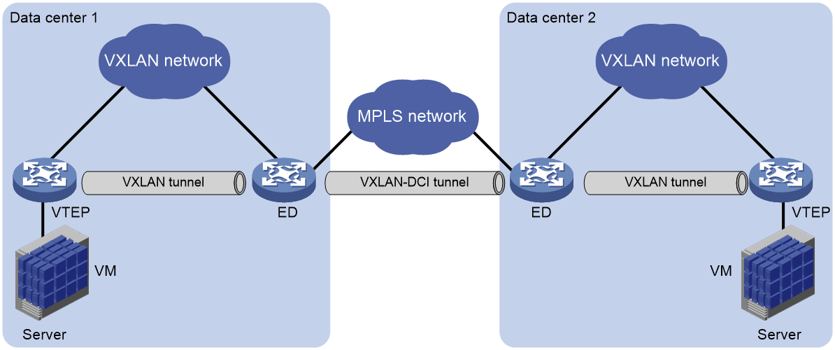
When data centers are interconnected through an MPLS L3VPN network, EVPN EDs also act as MPLS L3VPN PEs. To enable communication between the data centers, you must perform the following tasks on the EDs:
· Configure both MPLS L3VPN and EVPN.
· Configure the BGP EVPN address family and the BGP VPNv4 or VPNv6 address family to exchange routes.
Figure 4 Data centers interconnected through an MPLS L3VPN network
Enabling BGP VPNv4 or VPNv6 route advertisement for the BGP EVPN address family
1. Enter system view.
system-view
2. Enter BGP instance view.
bgp as-number [ instance instance-name ]
3. Enter BGP EVPN address family view.
address-family l2vpn evpn
4. Enable BGP VPNv4 or VPNv6 route advertisement for the BGP EVPN address family.
advertise l3vpn route [ replace-rt ][ advertise-policy policy-name ]
By default, BGP VPNv4 or VPNv6 routes are not advertised through the BGP EVPN address family.
After you execute this command, the device advertises BGP VPNv4 or VPNv6 routes as IP prefix advertisement routes through the BGP EVPN address family.
Enabling BGP EVPN route advertisement for the BGP VPNv4 or VPNv6 address family
1. Enter system view.
system-view
2. Enter BGP instance view.
bgp as-number [ instance instance-name ]
3. Enter BGP VPNv4 address family view or BGP VPNv6 address family view.
address-family { vpnv4 | vpnv6 }
4. Enable BGP EVPN route advertisement for the BGP VPNv4 or VPNv6 address family.
advertise evpn route [ replace-rt ][ advertise-policy policy-name ]
By default, BGP EVPN routes are not advertised through the BGP VPNv4 or VPNv6 address family.
After you execute this command, the device advertises IP prefix advertisement routes and MAC/IP advertisement routes that contain host route information through the BGP VPNv4 or VPNv6 address family.
Configuring EVPN-DCI dual-homing
About this task
For high availability and load sharing, you can deploy two EDs at a data center. To virtualize the redundant EDs into one device, you must configure the same virtual ED address on them.
Restrictions and guidelines
Do not configure a virtual ED address on the only ED of a data center.
On a redundant ED, the virtual ED address must be the IP address of a loopback interface, and it cannot be the BGP peer IP address of the ED.
Redundant EDs cannot provide access service for local VMs. They can act only as EDs. For correct communication, do not redistribute external routes on only one of the redundant EDs. However, you can redistribute the same external routes on both EDs.
EVPN-DCI dual-homing is mutually exclusive with EVPN distributed relay. Do not use the evpn edge group and evpn m-lag group commands together.
To use EVPN-DCI dual-homing, make sure the overlay and undelay networks are both IPv4 networks or both IPv6 networks.
Procedure
1. Enter system view.
system-view
2. Configure a virtual ED address.
evpn edge group { group-ipv4 | group-ipv6 }
By default, no virtual ED address is configured.
Configuring EVPN-DCI M-LAG
About this task
To set up an M-LAG system with two EDs, configure a virtual VTEP address on the EDs. The EDs will use the virtual VTEP address to set up VXLAN tunnels or VXLAN-DCI tunnels with VTEPs or remote EDs.
Restrictions and guidelines
Do not execute the evpn m-lag local command if you have configured EVPN-DCI M-LAG.
When you attach a user site to an M-LAG system, attach it to both M-LAG interfaces in an M-LAG group. Do not configure single-homed ACs on the member EDs.
Procedure
1. Enter system view.
system-view
2. Specify the virtual VTEP address.
evpn m-lag group { virtual-vtep-ipv4 | virtual-vtep-ipv6 }
By default, EVPN-DCI M-LAG is not configured.
3. Enter BGP instance view.
bgp as-number [ instance instance-name ]
4. Enter BGP EVPN address family view.
address-family l2vpn evpn
5. Enable the device to replace the next hop in advertised BGP EVPN routes with the virtual VTEP address.
nexthop evpn-m-lag group-address
The default settings are as follows:
¡ When advertising BGP EVPN routes to an EBGP peer or peer group, the device replaces the next hop with the IP address of the source interface used to establish BGP sessions.
¡ When advertising EBGP routes to an IBGP peer or peer group, the device does not modify the next hop.
EVPN-DCI configuration examples
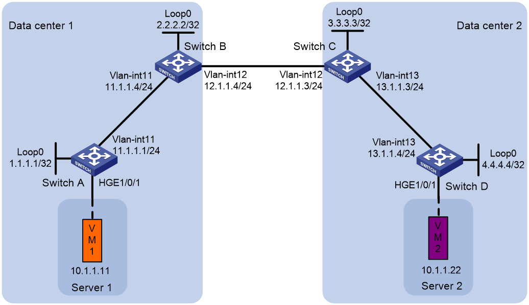
Example: Configuring a basic EVPN-DCI network
Network configuration
As shown in Figure 5:
· Configure VXLAN 10 on Switch A through Switch D to provide connectivity for the VMs in the data centers.
· Configure Switch A and Switch D as VTEPs, and configure Switch B and Switch C as EDs.
Procedure
|
|
IMPORTANT: By default, interfaces on the device operate in Layer 3 mode. In this example, you must use the port link-mode command to configure the interfaces that host Ethernet service instances to operate in Layer 2 mode. |
1. Configure IP addresses and unicast routing settings:
# Assign IP addresses to interfaces, as shown in Figure 5. (Details not shown.)
# Configure OSPF on the transport network for the switches to reach one another. (Details not shown.)
2. Configure Switch A:
# Enable L2VPN.
<SwitchA> system-view
[SwitchA] l2vpn enable
# Disable remote MAC address learning.
[SwitchA] vxlan tunnel mac-learning disable
# Create VXLAN 10 on VSI vpna.
[SwitchA] vsi vpna
[SwitchA-vsi-vpna] vxlan 10
[SwitchA-vsi-vpna-vxlan-10] quit
# Create an EVPN instance on VSI vpna. Configure the switch to automatically generate an RD, and manually configure a route target for the EVPN instance.
[SwitchA-vsi-vpna] evpn encapsulation vxlan
[SwitchA-vsi-vpna-evpn-vxlan] route-distinguisher auto
[SwitchA-vsi-vpna-evpn-vxlan] vpn-target 123:456
[SwitchA-vsi-vpna-evpn-vxlan] quit
[SwitchA-vsi-vpna] quit
# Configure BGP to advertise BGP EVPN routes.
[SwitchA] bgp 100
[SwitchA-bgp-default] peer 2.2.2.2 as-number 100
[SwitchA-bgp-default] peer 2.2.2.2 connect-interface loopback 0
[SwitchA-bgp-default] address-family l2vpn evpn
[SwitchA-bgp-default-evpn] peer 2.2.2.2 enable
[SwitchA-bgp-default-evpn] quit
[SwitchA-bgp-default] quit
# On HundredGigE 1/0/1, create Ethernet service instance 1000 to match VLAN 100.
[SwitchA] interface hundredgige 1/0/1
[SwitchA-HundredGigE1/0/1] service-instance 1000
[SwitchA-HundredGigE1/0/1-srv1000] encapsulation s-vid 100
# Map Ethernet service instance 1000 to VSI vpna.
[SwitchA-HundredGigE1/0/1-srv1000] xconnect vsi vpna
[SwitchA-HundredGigE1/0/1-srv1000] quit
3. Configure Switch B:
# Enable L2VPN.
<SwitchB> system-view
[SwitchB] l2vpn enable
# Disable remote MAC address learning.
[SwitchB] vxlan tunnel mac-learning disable
# Create VXLAN 10 on VSI vpna.
[SwitchB] vsi vpna
[SwitchB-vsi-vpna] vxlan 10
[SwitchB-vsi-vpna-vxlan-10] quit
# Create an EVPN instance on VSI vpna. Configure the switch to automatically generate an RD, and manually configure a route target for the EVPN instance.
[SwitchB-vsi-vpna] evpn encapsulation vxlan
[SwitchB-vsi-vpna-evpn-vxlan] route-distinguisher auto
[SwitchB-vsi-vpna-evpn-vxlan] vpn-target 123:456
[SwitchB-vsi-vpna-evpn-vxlan] quit
[SwitchB-vsi-vpna] quit
# Configure BGP to advertise BGP EVPN routes. Enable nexthop replacement for routes advertised to Switch A, and enable router MAC replacement for routes advertised to and received from Switch C.
[SwitchB] bgp 100
[SwitchB-bgp-default] peer 3.3.3.3 as-number 200
[SwitchB-bgp-default] peer 3.3.3.3 connect-interface loopback 0
[SwitchB-bgp-default] peer 3.3.3.3 ebgp-max-hop 64
[SwitchB-bgp-default] peer 1.1.1.1 as-number 100
[SwitchB-bgp-default] peer 1.1.1.1 connect-interface loopback 0
[SwitchB-bgp-default] address-family l2vpn evpn
[SwitchB-bgp-default-evpn] peer 3.3.3.3 enable
[SwitchB-bgp-default-evpn] peer 3.3.3.3 router-mac-local dci
[SwitchB-bgp-default-evpn] peer 1.1.1.1 enable
[SwitchB-bgp-default-evpn] peer 1.1.1.1 next-hop-local
[SwitchB-bgp-default-evpn] quit
[SwitchB-bgp-default] quit
4. Configure Switch C:
# Enable L2VPN.
<SwitchC> system-view
[SwitchC] l2vpn enable
# Disable remote MAC address learning.
[SwitchC] vxlan tunnel mac-learning disable
# Create VXLAN 10 on VSI vpna.
[SwitchC] vsi vpna
[SwitchC-vsi-vpna] vxlan 10
[SwitchC-vsi-vpna-vxlan-10] quit
# Create an EVPN instance on VSI vpna. Configure the switch to automatically generate an RD, and manually configure a route target for the EVPN instance.
[SwitchC-vsi-vpna] evpn encapsulation vxlan
[SwitchC-vsi-vpna-evpn-vxlan] route-distinguisher auto
[SwitchC-vsi-vpna-evpn-vxlan] vpn-target 123:456
[SwitchC-vsi-vpna-evpn-vxlan] quit
[SwitchC-vsi-vpna] quit
# Configure BGP to advertise BGP EVPN routes. Enable nexthop replacement for routes advertised to Switch D, and enable router MAC replacement for routes advertised to and received from Switch B.
[SwitchC] bgp 200
[SwitchC-bgp-default] peer 2.2.2.2 as-number 100
[SwitchC-bgp-default] peer 2.2.2.2 connect-interface loopback 0
[SwitchC-bgp-default] peer 2.2.2.2 ebgp-max-hop 64
[SwitchC-bgp-default] peer 4.4.4.4 as-number 200
[SwitchC-bgp-default] peer 4.4.4.4 connect-interface loopback 0
[SwitchC-bgp-default] address-family l2vpn evpn
[SwitchC-bgp-default-evpn] peer 2.2.2.2 enable
[SwitchC-bgp-default-evpn] peer 2.2.2.2 router-mac-local dci
[SwitchC-bgp-default-evpn] peer 4.4.4.4 enable
[SwitchC-bgp-default-evpn] peer 4.4.4.4 next-hop-local
[SwitchC-bgp-default-evpn] quit
[SwitchC-bgp-default] quit
5. Configure Switch D:
# Enable L2VPN.
<SwitchD> system-view
[SwitchD] l2vpn enable
# Disable remote MAC address learning.
[SwitchD] vxlan tunnel mac-learning disable
# Create VXLAN 10 on VSI vpna.
[SwitchD] vsi vpna
[SwitchD-vsi-vpna] vxlan 10
[SwitchD-vsi-vpna-vxlan-10] quit
# Create an EVPN instance on VSI vpna. Configure the switch to automatically generate an RD, and manually configure a route target for the EVPN instance.
[SwitchD-vsi-vpna] evpn encapsulation vxlan
[SwitchD-vsi-vpna-evpn-vxlan] route-distinguisher auto
[SwitchD-vsi-vpna-evpn-vxlan] vpn-target 123:456
[SwitchD-vsi-vpna-evpn-vxlan] quit
[SwitchD-vsi-vpna] quit
# Configure BGP to advertise BGP EVPN routes.
[SwitchD] bgp 200
[SwitchD-bgp-default] peer 3.3.3.3 as-number 200
[SwitchD-bgp-default] peer 3.3.3.3 connect-interface Loopback 0
[SwitchD-bgp-default] address-family l2vpn evpn
[SwitchD-bgp-default-evpn] peer 3.3.3.3 enable
[SwitchD-bgp-default-evpn] quit
[SwitchD-bgp-default] quit
# On HundredGigE 1/0/1, create Ethernet service instance 1000 to match VLAN 200.
[SwitchD] interface hundredgige 1/0/1
[SwitchD-HundredGigE1/0/1] service-instance 1000
[SwitchD-HundredGigE1/0/1-srv1000] encapsulation s-vid 200
# Map Ethernet service instance 1000 to VSI vpna.
[SwitchD-HundredGigE1/0/1-srv1000] xconnect vsi vpna
[SwitchD-HundredGigE1/0/1-srv1000] quit
Verifying the configuration
1. Verify the configuration on EDs. (This example uses Switch B.)
# Verify that the ED has discovered Switch A and Switch C through IMET routes and has established VXLAN and VXLAN-DCI tunnels to the switches.
[SwitchB] display evpn auto-discovery imet
Total number of automatically discovered peers: 2
VSI name: vpna
RD PE_address Tunnel_address Tunnel mode VXLAN ID
1:10 1.1.1.1 1.1.1.1 VXLAN 10
1:10 3.3.3.3 3.3.3.3 VXLAN-DCI 10
# Verify that the VXLAN and VXLAN-DCI tunnels on the ED are up.
[SwitchB] display interface tunnel
Tunnel0
Current state: UP
Line protocol state: UP
Description: Tunnel0 Interface
Bandwidth: 64 kbps
Maximum transmission unit: 1464
Internet protocol processing: Disabled
Last clearing of counters: Never
Tunnel source 2.2.2.2, destination 1.1.1.1
Tunnel protocol/transport UDP_VXLAN/IP
Last 300 seconds input rate: 0 bytes/sec, 0 bits/sec, 0 packets/sec
Last 300 seconds output rate: 0 bytes/sec, 0 bits/sec, 0 packets/sec
Input: 0 packets, 0 bytes, 0 drops
Output: 0 packets, 0 bytes, 0 drops
Tunnel1
Current state: UP
Line protocol state: UP
Description: Tunnel1 Interface
Bandwidth: 64 kbps
Maximum transmission unit: 1464
Internet protocol processing: Disabled
Last clearing of counters: Never
Tunnel source 2.2.2.2, destination 3.3.3.3
Tunnel protocol/transport UDP_VXLAN-DCI/IP
Last 300 seconds input rate: 0 bytes/sec, 0 bits/sec, 0 packets/sec
Last 300 seconds output rate: 0 bytes/sec, 0 bits/sec, 0 packets/sec
Input: 0 packets, 0 bytes, 0 drops
Output: 0 packets, 0 bytes, 0 drops
# Verify that the VXLAN and VXLAN-DCI tunnels have been assigned to the VXLAN.
[SwitchB] display l2vpn vsi name vpna verbose
VSI Name: vpna
VSI Index : 0
VSI State : Up
MTU : -
Diffserv Mode : -
Bandwidth : -
Broadcast Restrain : -
Multicast Restrain : -
Unknown Unicast Restrain: -
MAC Learning : -
MAC Table Limit : -
MAC Learning rate : -
Drop Unknown : -
PW Redundancy Mode : Independent
DSCP : -
Service Class : -
Flooding : Enabled
ESI : 0000.0000.0000.0000.0000
Redundancy Mode : All-active
Statistics : Disabled
VXLAN ID : 10
EVPN Encapsulation : VXLAN
Tunnels:
Tunnel Name Link ID State Type Flood proxy
Tunnel0 0x5000000 UP Auto Disabled
Tunnel1 0x5000001 UP Auto Disabled
# Verify that the ED has generated EVPN MAC address entries for the VMs.
[SwitchB] display evpn route mac
Flags: D - Dynamic B - BGP L - Local active
G - Gateway S - Static M - Mapping
VSI name: vpna
MAC address Link ID/Name Flags Next hop
0001-0001-0011 Tunnel0 B 1.1.1.1
0001-0001-0033 Tunnel1 B 3.3.3.3
2. Verify that VM 1 and VM 2 can communicate. (Details not shown.)
Example: Configuring EVPN-DCI intermediate VXLAN mapping
Network configuration
As shown in Figure 6:
· Configure VXLAN 10 on VTEP Switch A and ED Switch B, and configure VXLAN 30 on VTEP Switch D and ED Switch C.
· Configure intermediate VXLAN mapping for VXLAN 10 and VXLAN 30 to have Layer 2 connectivity:
¡ Map VXLAN 10 to intermediate VXLAN 500 on Switch B.
¡ Map VXLAN 30 to intermediate VXLAN 500 on Switch C.
Procedure
|
|
IMPORTANT: By default, interfaces on the device operate in Layer 3 mode. In this example, you must use the port link-mode command to configure the interfaces that host Ethernet service instances to operate in Layer 2 mode. |
1. Configure IP addresses and unicast routing settings:
# Assign IP addresses to interfaces, as shown in Figure 6. (Details not shown.)
# Configure OSPF on the transport network for the switches to reach one another. (Details not shown.)
2. Configure Switch A:
# Enable L2VPN.
<SwitchA> system-view
[SwitchA] l2vpn enable
# Disable remote MAC address learning.
[SwitchA] vxlan tunnel mac-learning disable
# Create VXLAN 10 on VSI vpna.
[SwitchA] vsi vpna
[SwitchA-vsi-vpna] vxlan 10
[SwitchA-vsi-vpna-vxlan-10] quit
# Create an EVPN instance on VSI vpna. Configure the switch to automatically generate an RD and a route target for the EVPN instance.
[SwitchA-vsi-vpna] evpn encapsulation vxlan
[SwitchA-vsi-vpna-evpn-vxlan] route-distinguisher auto
[SwitchA-vsi-vpna-evpn-vxlan] vpn-target auto
[SwitchA-vsi-vpna-evpn-vxlan] quit
[SwitchA-vsi-vpna] quit
# Configure BGP to advertise BGP EVPN routes.
[SwitchA] bgp 100
[SwitchA-bgp-default] peer 2.2.2.2 as-number 100
[SwitchA-bgp-default] peer 2.2.2.2 connect-interface loopback 0
[SwitchA-bgp-default] address-family l2vpn evpn
[SwitchA-bgp-default-evpn] peer 2.2.2.2 enable
[SwitchA-bgp-default-evpn] quit
[SwitchA-bgp-default] quit
# On HundredGigE 1/0/1, create Ethernet service instance 1000 to match VLAN 100.
[SwitchA] interface hundredgige 1/0/1
[SwitchA-HundredGigE1/0/1] service-instance 1000
[SwitchA-HundredGigE1/0/1-srv1000] encapsulation s-vid 100
# Map Ethernet service instance 1000 to VSI vpna.
[SwitchA-HundredGigE1/0/1-srv1000] xconnect vsi vpna
[SwitchA-HundredGigE1/0/1-srv1000] quit
3. Configure Switch B:
# Enable L2VPN.
<SwitchB> system-view
[SwitchB] l2vpn enable
# Disable remote MAC address learning.
[SwitchB] vxlan tunnel mac-learning disable
# Create VXLAN 10 on VSI vpna.
[SwitchB] vsi vpna
[SwitchB-vsi-vpna] vxlan 10
[SwitchB-vsi-vpna-vxlan-10] quit
# Create an EVPN instance on VSI vpna. Configure the switch to automatically generate an RD and a route target for the EVPN instance.
[SwitchB-vsi-vpna] evpn encapsulation vxlan
[SwitchB-vsi-vpna-evpn-vxlan] route-distinguisher auto
[SwitchB-vsi-vpna-evpn-vxlan] vpn-target auto
# Map local VXLAN 10 to intermediate VXLAN 500.
[SwitchB-vsi-vpna-evpn-vxlan] mapping vni 500
[SwitchB-vsi-vpna-evpn-vxlan] quit
[SwitchB-vsi-vpna] quit
# Create VXLAN 500 on VSI vpnb. The switch will replace the VXLAN ID of VXLAN 10's traffic with VXLAN ID 500 when performing Layer 2 forwarding.
[SwitchB] vsi vpnb
[SwitchB-vsi-vpnb] vxlan 500
[SwitchB-vsi-vpnb-vxlan-500] quit
# Create an EVPN instance on VSI vpnb. Configure the switch to automatically generate an RD, and manually configure a route target for the EVPN instance.
[SwitchB-vsi-vpnb] evpn encapsulation vxlan
[SwitchB-vsi-vpnb-evpn-vxlan] route-distinguisher auto
[SwitchB-vsi-vpnb-evpn-vxlan] vpn-target 123:456
[SwitchB-vsi-vpnb-evpn-vxlan] quit
[SwitchB-vsi-vpnb] quit
# Configure BGP to advertise BGP EVPN routes. Enable nexthop replacement for routes advertised to Switch A, and enable router MAC replacement for routes advertised to and received from Switch C.
[SwitchB] bgp 100
[SwitchB-bgp-default] peer 3.3.3.3 as-number 200
[SwitchB-bgp-default] peer 3.3.3.3 connect-interface loopback 0
[SwitchB-bgp-default] peer 3.3.3.3 ebgp-max-hop 64
[SwitchB-bgp-default] peer 1.1.1.1 as-number 100
[SwitchB-bgp-default] peer 1.1.1.1 connect-interface loopback 0
[SwitchB-bgp-default] address-family l2vpn evpn
[SwitchB-bgp-default-evpn] peer 3.3.3.3 enable
[SwitchB-bgp-default-evpn] peer 3.3.3.3 router-mac-local dci
[SwitchB-bgp-default-evpn] peer 1.1.1.1 enable
[SwitchB-bgp-default-evpn] peer 1.1.1.1 next-hop-local
[SwitchB-bgp-default-evpn] quit
[SwitchB-bgp-default] quit
4. Configure Switch C:
# Enable L2VPN.
<SwitchC> system-view
[SwitchC] l2vpn enable
# Disable remote MAC address learning.
[SwitchC] vxlan tunnel mac-learning disable
# Create VXLAN 30 on VSI vpna.
[SwitchC] vsi vpna
[SwitchC-vsi-vpna] vxlan 30
[SwitchC-vsi-vpna-vxlan-30] quit
# Create an EVPN instance on VSI vpna. Configure the switch to automatically generate an RD and a route target for the EVPN instance.
[SwitchC-vsi-vpna] evpn encapsulation vxlan
[SwitchC-vsi-vpna-evpn-vxlan] route-distinguisher auto
[SwitchC-vsi-vpna-evpn-vxlan] vpn-target auto
# Map local VXLAN 30 to intermediate VXLAN 500.
[SwitchC-vsi-vpna-evpn-vxlan] mapping vni 500
[SwitchC-vsi-vpna-evpn-vxlan] quit
[SwitchC-vsi-vpna] quit
# Create VXLAN 500 on VSI vpnb. The switch will replace the VXLAN ID of VXLAN 30's traffic with VXLAN ID 500 when performing Layer 2 forwarding.
[SwitchC] vsi vpnb
[SwitchC-vsi-vpnb] vxlan 500
[SwitchC-vsi-vpnb-vxlan-500] quit
# Create an EVPN instance on VSI vpnb. Configure the switch to automatically generate an RD, and manually configure a route target for the EVPN instance.
[SwitchC-vsi-vpnb] evpn encapsulation vxlan
[SwitchC-vsi-vpnb-evpn-vxlan] route-distinguisher auto
[SwitchC-vsi-vpnb-evpn-vxlan] vpn-target 123:456
[SwitchC-vsi-vpnb-evpn-vxlan] quit
[SwitchC-vsi-vpnb] quit
# Configure BGP to advertise BGP EVPN routes. Enable nexthop replacement for routes advertised to Switch D, and enable router MAC replacement for routes advertised to and received from Switch B.
[SwitchC] bgp 200
[SwitchC-bgp-default] peer 2.2.2.2 as-number 100
[SwitchC-bgp-default] peer 2.2.2.2 connect-interface loopback 0
[SwitchC-bgp-default] peer 2.2.2.2 ebgp-max-hop 64
[SwitchC-bgp-default] peer 4.4.4.4 as-number 200
[SwitchC-bgp-default] peer 4.4.4.4 connect-interface loopback 0
[SwitchC-bgp-default] address-family l2vpn evpn
[SwitchC-bgp-default-evpn] peer 2.2.2.2 enable
[SwitchC-bgp-default-evpn] peer 2.2.2.2 router-mac-local dci
[SwitchC-bgp-default-evpn] peer 4.4.4.4 enable
[SwitchC-bgp-default-evpn] peer 4.4.4.4 next-hop-local
[SwitchC-bgp-default-evpn] quit
[SwitchC-bgp-default] quit
5. Configure Switch D:
# Enable L2VPN.
<SwitchD> system-view
[SwitchD] l2vpn enable
# Disable remote MAC address learning.
[SwitchD] vxlan tunnel mac-learning disable
# Create VXLAN 30 on VSI vpna.
[SwitchD] vsi vpna
[SwitchD-vsi-vpna] vxlan 30
[SwitchD-vsi-vpna-vxlan-30] quit
# Create an EVPN instance on VSI vpna. Configure the switch to automatically generate an RD and a route target for the EVPN instance.
[SwitchD-vsi-vpna] evpn encapsulation vxlan
[SwitchD-vsi-vpna-evpn-vxlan] route-distinguisher auto
[SwitchD-vsi-vpna-evpn-vxlan] vpn-target auto
[SwitchD-vsi-vpna-evpn-vxlan] quit
[SwitchD-vsi-vpna] quit
# Configure BGP to advertise BGP EVPN routes.
[SwitchD] bgp 200
[SwitchD-bgp-default] peer 3.3.3.3 as-number 200
[SwitchD-bgp-default] peer 3.3.3.3 connect-interface Loopback 0
[SwitchD-bgp-default] address-family l2vpn evpn
[SwitchD-bgp-default-evpn] peer 3.3.3.3 enable
[SwitchD-bgp-default-evpn] quit
[SwitchD-bgp-default] quit
# On HundredGigE 1/0/1, create Ethernet service instance 1000 to match VLAN 200.
[SwitchD] interface hundredgige 1/0/1
[SwitchD-HundredGigE1/0/1] service-instance 1000
[SwitchD-HundredGigE1/0/1-srv1000] encapsulation s-vid 200
# Map Ethernet service instance 1000 to VSI vpna.
[SwitchD-HundredGigE1/0/1-srv1000] xconnect vsi vpna
[SwitchD-HundredGigE1/0/1-srv1000] quit
Verifying the configuration
1. Verify the configuration on EDs. (This example uses Switch B.)
# Verify that the ED has discovered Switch A and Switch C through IMET routes and has established VXLAN and VXLAN-DCI tunnels to the switches.
[SwitchB] display evpn auto-discovery imet
Total number of automatically discovered peers: 2
VSI name: vpna
RD PE_address Tunnel_address Tunnel mode VXLAN ID
1:10 1.1.1.1 1.1.1.1 VXLAN 10
1:500 3.3.3.3 3.3.3.3 VXLAN-DCI 500
# Verify that the VXLAN and VXLAN-DCI tunnels on the ED are up.
[SwitchB] display interface tunnel
Tunnel0
Current state: UP
Line protocol state: UP
Description: Tunnel0 Interface
Bandwidth: 64 kbps
Maximum transmission unit: 1464
Internet protocol processing: Disabled
Last clearing of counters: Never
Tunnel source 2.2.2.2, destination 1.1.1.1
Tunnel protocol/transport UDP_VXLAN/IP
Last 300 seconds input rate: 0 bytes/sec, 0 bits/sec, 0 packets/sec
Last 300 seconds output rate: 0 bytes/sec, 0 bits/sec, 0 packets/sec
Input: 0 packets, 0 bytes, 0 drops
Output: 0 packets, 0 bytes, 0 drops
Tunnel1
Current state: UP
Line protocol state: UP
Description: Tunnel1 Interface
Bandwidth: 64 kbps
Maximum transmission unit: 1464
Internet protocol processing: Disabled
Last clearing of counters: Never
Tunnel source 2.2.2.2, destination 3.3.3.3
Tunnel protocol/transport UDP_VXLAN-DCI/IP
Last 300 seconds input rate: 0 bytes/sec, 0 bits/sec, 0 packets/sec
Last 300 seconds output rate: 0 bytes/sec, 0 bits/sec, 0 packets/sec
Input: 0 packets, 0 bytes, 0 drops
Output: 0 packets, 0 bytes, 0 drops
# Verify that the VXLAN and VXLAN-DCI tunnels have been assigned to VXLAN 10, and that no tunnels are assigned to intermediate VXLAN 500.
[SwitchB] display l2vpn vsi verbose
VSI Name: vpna
VSI Index : 0
VSI State : Up
MTU : -
Diffserv Mode : -
Bandwidth : -
Broadcast Restrain : -
Multicast Restrain : -
Unknown Unicast Restrain: -
MAC Learning : -
MAC Table Limit : -
MAC Learning rate : -
Drop Unknown : -
PW Redundancy Mode : Independent
DSCP : -
Service Class : -
Flooding : Enabled
ESI : 0000.0000.0000.0000.0000
Redundancy Mode : All-active
Statistics : Disabled
VXLAN ID : 10
EVPN Encapsulation : VXLAN
Tunnels:
Tunnel Name Link ID State Type Flood proxy
Tunnel0 0x5000000 UP Auto Disabled
Tunnel1 0x5000001 UP Auto Disabled
VSI Name: vpnb
VSI Index : 1
VSI State : Down
MTU : -
Diffserv Mode : -
Bandwidth : -
Broadcast Restrain : -
Multicast Restrain : -
Unknown Unicast Restrain: -
MAC Learning : -
MAC Table Limit : -
MAC Learning rate : -
Drop Unknown : -
PW Redundancy Mode : Independent
DSCP : -
Service Class : -
Flooding : Enabled
ESI : 0000.0000.0000.0000.0000
Redundancy Mode : All-active
Statistics : Disabled
VXLAN ID : 500
EVPN Encapsulation : VXLAN
# Verify that the ED has generated EVPN MAC address entries for the VMs, and the remote MAC address entry has the M flag.
[SwitchB] display evpn route mac
Flags: D - Dynamic B - BGP L - Local active
G - Gateway S - Static M - Mapping
VSI name: vpna
MAC address Link ID/Name Flags Next hop
0001-0001-0011 Tunnel0 B 1.1.1.1
0001-0001-0033 Tunnel1 BM 3.3.3.3
2. Verify that VM 1 and VM 2 can communicate. (Details not shown.)
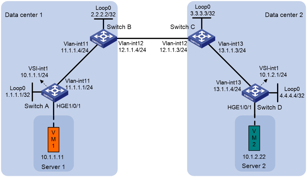
Example: Configuring EVPN-DCI IPv4 Layer 3 communication
Network configuration
As shown in Figure 7:
· Configure VXLAN 10 for data center 1, and configure VXLAN 20 for data center 2.
· Configure Switch A and Switch D as distributed EVPN gateways to perform Layer 3 forwarding between VXLAN 10 and VXLAN 20.
· Configure Switch B and Switch C as EDs.
Procedure
|
|
IMPORTANT: By default, interfaces on the device operate in Layer 3 mode. In this example, you must use the port link-mode command to configure the interfaces that host Ethernet service instances to operate in Layer 2 mode. |
1. Configure IP addresses and unicast routing settings:
# On VM 1, specify 10.1.1.1 as the gateway address. On VM 2, specify 10.1.2.1 as the gateway address. (Details not shown.)
# Assign IP addresses to interfaces, as shown in Figure 7. (Details not shown.)
# Configure OSPF on the transport network for the switches to reach one another. (Details not shown.)
2. Configure Switch A:
# Enable L2VPN.
<SwitchA> system-view
[SwitchA] l2vpn enable
# Disable remote MAC address learning and remote ARP learning.
[SwitchA] vxlan tunnel mac-learning disable
[SwitchA] vxlan tunnel arp-learning disable
# Create VXLAN 10 on VSI vpna.
[SwitchA] vsi vpna
[SwitchA-vsi-vpna] vxlan 10
[SwitchA-vsi-vpna-vxlan-10] quit
# Create an EVPN instance on VSI vpna. Configure the switch to automatically generate an RD and a route target for the EVPN instance.
[SwitchA-vsi-vpna] evpn encapsulation vxlan
[SwitchA-vsi-vpna-evpn-vxlan] route-distinguisher auto
[SwitchA-vsi-vpna-evpn-vxlan] vpn-target auto
[SwitchA-vsi-vpna-evpn-vxlan] quit
[SwitchA-vsi-vpna] quit
# Configure BGP to advertise BGP EVPN routes.
[SwitchA] bgp 100
[SwitchA-bgp-default] peer 2.2.2.2 as-number 100
[SwitchA-bgp-default] peer 2.2.2.2 connect-interface loopback 0
[SwitchA-bgp-default] address-family l2vpn evpn
[SwitchA-bgp-default-evpn] peer 2.2.2.2 enable
[SwitchA-bgp-default-evpn] quit
[SwitchA-bgp-default] quit
# On HundredGigE 1/0/1, create Ethernet service instance 1000 to match VLAN 100.
[SwitchA] interface hundredgige 1/0/1
[SwitchA-HundredGigE1/0/1] service-instance 1000
[SwitchA-HundredGigE1/0/1-srv1000] encapsulation s-vid 100
# Map Ethernet service instance 1000 to VSI vpna.
[SwitchA-HundredGigE1/0/1-srv1000] xconnect vsi vpna
[SwitchA-HundredGigE1/0/1-srv1000] quit
# Configure RD and route target settings for VPN instance vpn1.
[SwitchA] ip vpn-instance vpn1
[SwitchA-vpn-instance-vpn1] route-distinguisher 1:1
[SwitchA-vpn-instance-vpn1] address-family ipv4
[SwitchA-vpn-ipv4-vpn1] vpn-target 2:2
[SwitchA-vpn-ipv4-vpn1] quit
[SwitchA-vpn-instance-vpn1] address-family evpn
[SwitchA-vpn-evpn-vpn1] vpn-target 1:1
[SwitchA-vpn-evpn-vpn1] quit
[SwitchA-vpn-instance-vpn1] quit
# Configure VSI-interface 1 as a distributed gateway.
[SwitchA] interface vsi-interface 1
[SwitchA-Vsi-interface1] ip binding vpn-instance vpn1
[SwitchA-Vsi-interface1] ip address 10.1.1.1 255.255.255.0
[SwitchA-Vsi-interface1] mac-address 1-1-1
[SwitchA-Vsi-interface1] distributed-gateway local
[SwitchA-Vsi-interface1] quit
# Create VSI-interface 2. Associate VSI-interface 2 with VPN instance vpn1, and configure the L3 VXLAN ID as 1000 for the VPN instance.
[SwitchA] interface vsi-interface 2
[SwitchA-Vsi-interface2] ip binding vpn-instance vpn1
[SwitchA-Vsi-interface2] l3-vni 1000
[SwitchA-Vsi-interface2] quit
# Specify VSI-interface 1 as the gateway interface for VSI vpna.
[SwitchA] vsi vpna
[SwitchA-vsi-vpna] gateway vsi-interface 1
[SwitchA-vsi-vpna] quit
3. Configure Switch B:
# Enable L2VPN.
<SwitchB> system-view
[SwitchB] l2vpn enable
# Disable remote MAC address learning and remote ARP learning.
[SwitchB] vxlan tunnel mac-learning disable
[SwitchB] vxlan tunnel arp-learning disable
# Configure BGP to advertise BGP EVPN routes. Enable nexthop replacement for routes advertised to Switch A, and enable router MAC replacement for routes advertised to and received from Switch C.
[SwitchB] bgp 100
[SwitchB-bgp-default] peer 3.3.3.3 as-number 200
[SwitchB-bgp-default] peer 3.3.3.3 connect-interface loopback 0
[SwitchB-bgp-default] peer 3.3.3.3 ebgp-max-hop 64
[SwitchB-bgp-default] peer 1.1.1.1 as-number 100
[SwitchB-bgp-default] peer 1.1.1.1 connect-interface loopback 0
[SwitchB-bgp-default] address-family l2vpn evpn
[SwitchB-bgp-default-evpn] peer 3.3.3.3 enable
[SwitchB-bgp-default-evpn] peer 3.3.3.3 router-mac-local dci
[SwitchB-bgp-default-evpn] peer 1.1.1.1 enable
[SwitchB-bgp-default-evpn] peer 1.1.1.1 next-hop-local
[SwitchB-bgp-default-evpn] quit
[SwitchB-bgp-default] quit
# Configure RD and route target settings for VPN instance vpn1.
[SwitchB] ip vpn-instance vpn1
[SwitchB-vpn-instance-vpn1] route-distinguisher 1:2
[SwitchB-vpn-instance-vpn1] address-family ipv4
[SwitchB-vpn-ipv4-vpn1] vpn-target 2:2
[SwitchB-vpn-ipv4-vpn1] quit
[SwitchB-vpn-instance-vpn1] address-family evpn
[SwitchB-vpn-evpn-vpn1] vpn-target 1:1
[SwitchB-vpn-evpn-vpn1] quit
[SwitchB-vpn-instance-vpn1] quit
# Create VSI-interface 2. Associate VSI-interface 2 with VPN instance vpn1, and configure the L3 VXLAN ID as 1000 for the VPN instance.
[SwitchB] interface vsi-interface 2
[SwitchB-Vsi-interface2] ip binding vpn-instance vpn1
[SwitchB-Vsi-interface2] l3-vni 1000
[SwitchB-Vsi-interface2] quit
4. Configure Switch C:
# Enable L2VPN.
<SwitchC> system-view
[SwitchC] l2vpn enable
# Disable remote MAC address learning and remote ARP learning.
[SwitchC] vxlan tunnel mac-learning disable
[SwitchC] vxlan tunnel arp-learning disable
# Configure BGP to advertise BGP EVPN routes. Enable nexthop replacement for routes advertised to Switch D, and enable router MAC replacement for routes advertised to and received from Switch B.
[SwitchC] bgp 200
[SwitchC-bgp-default] peer 2.2.2.2 as-number 100
[SwitchC-bgp-default] peer 2.2.2.2 connect-interface Loopback 0
[SwitchC-bgp-default] peer 2.2.2.2 ebgp-max-hop 64
[SwitchC-bgp-default] peer 4.4.4.4 as-number 200
[SwitchC-bgp-default] peer 4.4.4.4 connect-interface Loopback 0
[SwitchC-bgp-default] address-family l2vpn evpn
[SwitchC-bgp-default-evpn] peer 2.2.2.2 enable
[SwitchC-bgp-default-evpn] peer 2.2.2.2 router-mac-local dci
[SwitchC-bgp-default-evpn] peer 4.4.4.4 enable
[SwitchC-bgp-default-evpn] peer 4.4.4.4 next-hop-local
[SwitchC-bgp-default-evpn] quit
[SwitchC-bgp-default] quit
# Configure RD and route target settings for VPN instance vpn1.
[SwitchC] ip vpn-instance vpn1
[SwitchC-vpn-instance-vpn1] route-distinguisher 1:3
[SwitchC-vpn-instance-vpn1] address-family ipv4
[SwitchC-vpn-ipv4-vpn1] vpn-target 2:2
[SwitchC-vpn-ipv4-vpn1] quit
[SwitchC-vpn-instance-vpn1] address-family evpn
[SwitchC-vpn-evpn-vpn1] vpn-target 1:1
[SwitchC-vpn-evpn-vpn1] quit
[SwitchC-vpn-instance-vpn1] quit
# Create VSI-interface 2. Associate VSI-interface 2 with VPN instance vpn1, and configure the L3 VXLAN ID as 1000 for the VPN instance.
[SwitchC] interface vsi-interface 2
[SwitchC-Vsi-interface2] ip binding vpn-instance vpn1
[SwitchC-Vsi-interface2] l3-vni 1000
[SwitchC-Vsi-interface2] quit
5. Configure Switch D:
# Enable L2VPN.
<SwitchD> system-view
[SwitchD] l2vpn enable
# Disable remote MAC address learning and remote ARP learning.
[SwitchD] vxlan tunnel mac-learning disable
[SwitchD] vxlan tunnel arp-learning disable
# Create an EVPN instance on VSI vpnb. Configure the switch to automatically generate an RD and a route target for the EVPN instance.
[SwitchD] vsi vpnb
[SwitchD-vsi-vpnb] evpn encapsulation vxlan
[SwitchD-vsi-vpnb-evpn-vxlan] route-distinguisher auto
[SwitchD-vsi-vpnb-evpn-vxlan] vpn-target auto
[SwitchD-vsi-vpnb-evpn-vxlan] quit
# Create VXLAN 20 on VSI vpnb.
[SwitchD-vsi-vpnb] vxlan 20
[SwitchD-vsi-vpnb-vxlan-20] quit
[SwitchD-vsi-vpnb] quit
# Configure BGP to advertise BGP EVPN routes.
[SwitchD] bgp 200
[SwitchD-bgp-default] peer 3.3.3.3 as-number 200
[SwitchD-bgp-default] peer 3.3.3.3 connect-interface Loopback 0
[SwitchD-bgp-default] address-family l2vpn evpn
[SwitchD-bgp-default-evpn] peer 3.3.3.3 enable
[SwitchD-bgp-default-evpn] quit
[SwitchD-bgp-default] quit
# On HundredGigE 1/0/1, create Ethernet service instance 3000 to match VLAN 3.
[SwitchD] interface hundredgige 1/0/1
[SwitchD-HundredGigE1/0/1] service-instance 3000
[SwitchD-HundredGigE1/0/1-srv3000] encapsulation s-vid 3
# Map Ethernet service instance 3000 to VSI vpnb.
[SwitchD-HundredGigE1/0/1-srv3000] xconnect vsi vpnb
[SwitchD-HundredGigE1/0/1-srv3000] quit
# Configure RD and route target settings for VPN instance vpn1.
[SwitchD] ip vpn-instance vpn1
[SwitchD-vpn-instance-vpn1] route-distinguisher 1:4
[SwitchD-vpn-instance-vpn1] address-family ipv4
[SwitchD-vpn-ipv4-vpn1] vpn-target 2:2
[SwitchD-vpn-ipv4-vpn1] quit
[SwitchD-vpn-instance-vpn1] address-family evpn
[SwitchD-vpn-evpn-vpn1] vpn-target 1:1
[SwitchD-vpn-evpn-vpn1] quit
[SwitchD-vpn-instance-vpn1] quit
# Configure VSI-interface 1 as a distributed gateway.
[SwitchD] interface vsi-interface 1
[SwitchD-Vsi-interface1] ip binding vpn-instance vpn1
[SwitchD-Vsi-interface1] ip address 10.1.2.1 255.255.255.0
[SwitchD-Vsi-interface1] mac-address 1-2-1
[SwitchD-Vsi-interface1] distributed-gateway local
[SwitchD-Vsi-interface1] quit
# Create VSI-interface 2. Associate VSI-interface 2 with VPN instance vpn1, and configure the L3 VXLAN ID as 1000 for the VPN instance.
[SwitchD] interface vsi-interface 2
[SwitchD-Vsi-interface2] ip binding vpn-instance vpn1
[SwitchD-Vsi-interface2] l3-vni 1000
[SwitchD-Vsi-interface2] quit
# Specify VSI-interface 1 as the gateway interface for VSI vpnb.
[SwitchD] vsi vpnb
[SwitchD-vsi-vpnb] gateway vsi-interface 1
[SwitchD-vsi-vpnb] quit
Verifying the configuration
1. Verify the configuration on EDs. (This example uses Switch B.)
# Verify that the ED has discovered Switch A and Switch C through MAC/IP advertisement routes and IP prefix advertisement routes, and has established VXLAN and VXLAN-DCI tunnels to the switches.
[SwitchB] display evpn auto-discovery macip-prefix
Destination IP Source IP L3VNI Tunnel mode OutgoingInterface
1.1.1.1 2.2.2.2 1000 VXLAN Vsi-interface2
3.3.3.3 2.2.2.2 1000 VXLAN-DCI Vsi-interface2
# Verify that the VXLAN and VXLAN-DCI tunnels on the ED are up.
[SwitchB] display interface tunnel
Tunnel0
Current state: UP
Line protocol state: UP
Description: Tunnel0 Interface
Bandwidth: 64 kbps
Maximum transmission unit: 1464
Internet protocol processing: Disabled
Last clearing of counters: Never
Tunnel source 2.2.2.2, destination 1.1.1.1
Tunnel protocol/transport UDP_VXLAN/IP
Last 300 seconds input rate: 0 bytes/sec, 0 bits/sec, 0 packets/sec
Last 300 seconds output rate: 0 bytes/sec, 0 bits/sec, 0 packets/sec
Input: 0 packets, 0 bytes, 0 drops
Output: 0 packets, 0 bytes, 0 drops
Tunnel1
Current state: UP
Line protocol state: UP
Description: Tunnel1 Interface
Bandwidth: 64 kbps
Maximum transmission unit: 1464
Internet protocol processing: Disabled
Last clearing of counters: Never
Tunnel source 2.2.2.2, destination 3.3.3.3
Tunnel protocol/transport UDP_VXLAN-DCI/IP
Last 300 seconds input rate: 0 bytes/sec, 0 bits/sec, 0 packets/sec
Last 300 seconds output rate: 0 bytes/sec, 0 bits/sec, 0 packets/sec
Input: 0 packets, 0 bytes, 0 drops
Output: 0 packets, 0 bytes, 0 drops
# Verify that the ED has EVPN ARP entries and EVPN routes for the VMs.
[SwitchB] display arp vpn-instance vpn1
Type: S-Static D-Dynamic O-Openflow R-Rule I-Invalid
IP address MAC address VLAN/VSI name Interface Aging Type
1.1.1.1 0031-1900-0000 0 Tunnel0 N/A R
3.3.3.3 0031-3900-0000 0 Tunnel1 N/A R
[SwitchB] display ip routing-table vpn-instance vpn1
Destinations : 4 Routes : 4
Destination/Mask Proto Pre Cost NextHop Interface
10.1.1.0/24 BGP 255 0 1.1.1.1 Vsi2
10.1.1.11/32 BGP 255 0 1.1.1.1 Vsi2
10.1.2.0/24 BGP 255 0 3.3.3.3 Vsi2
10.1.2.22/32 BGP 255 0 3.3.3.3 Vsi2
2. Verify that VM 1 and VM 2 can communicate. (Details not shown.)
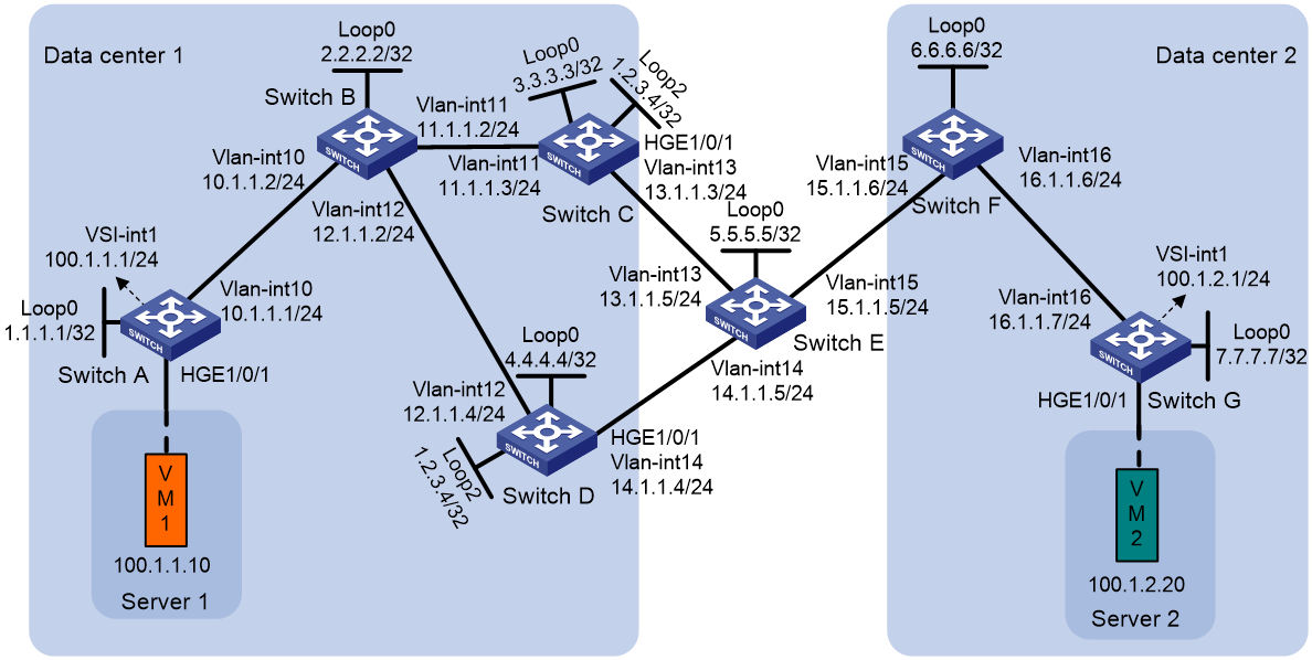
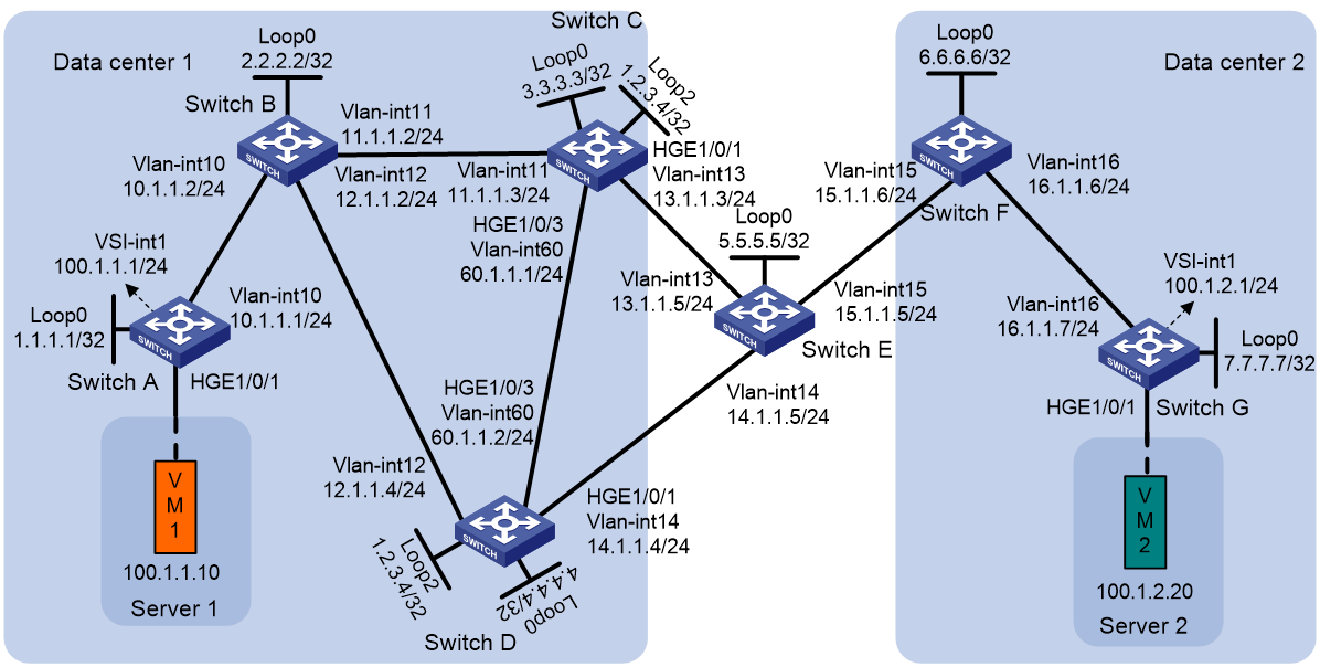
Example: Configuring EVPN-DCI dual-homing
Network configuration
As shown in Figure 8:
· Configure VXLAN 10 for data center 1, and configure VXLAN 20 for data center 2.
· Configure Switch A and Switch G as distributed EVPN gateways to perform Layer 3 forwarding between VXLAN 10 and VXLAN 20.
· Configure Switch C and Switch D as EDs of data center 1, and configure Switch F as the ED of data center 2.
· Configure Switch B as an RR.
|
|
NOTE: This example provides configuration of IPv4 sites over an IPv4 underlay network. The configuration procedure does not differ between IPv4 and IPv6 sites or underlay networks. |
Procedure
1. Configure IP addresses and unicast routing settings:
# On VM 1, specify 100.1.1.1 as the gateway address. On VM 2, specify 100.1.2.1 as the gateway address. (Details not shown.)
# Assign IP addresses to the interfaces, as shown in Figure 8. (Details not shown.)
# Configure OSPF for the switches to reach one another. (Details not shown.)
2. Configure Switch A:
# Enable L2VPN.
<SwitchA> system-view
[SwitchA] l2vpn enable
# Disable remote MAC address learning and remote ARP learning.
[SwitchA] vxlan tunnel mac-learning disable
[SwitchA] vxlan tunnel arp-learning disable
# Create VXLAN 10 on VSI vpna.
[SwitchA] vsi vpna
[SwitchA-vsi-vpna] vxlan 10
[SwitchA-vsi-vpna-vxlan-10] quit
# Create an EVPN instance on VSI vpna. Configure the switch to automatically generate an RD and a route target for the EVPN instance.
[SwitchA-vsi-vpna] evpn encapsulation vxlan
[SwitchA-vsi-vpna-evpn-vxlan] route-distinguisher auto
[SwitchA-vsi-vpna-evpn-vxlan] vpn-target auto
[SwitchA-vsi-vpna-evpn-vxlan] quit
[SwitchA-vsi-vpna] quit
# Configure BGP to advertise BGP EVPN routes.
[SwitchA] bgp 100
[SwitchA-bgp-default] peer 2.2.2.2 as-number 100
[SwitchA-bgp-default] peer 2.2.2.2 connect-interface loopback 0
[SwitchA-bgp-default] address-family l2vpn evpn
[SwitchA-bgp-default-evpn] peer 2.2.2.2 enable
[SwitchA-bgp-default-evpn] quit
[SwitchA-bgp-default] quit
# On HundredGigE 1/0/1, create Ethernet service instance 1000 to match VLAN 100.
[SwitchA] interface hundredgige 1/0/1
[SwitchA-HundredGigE1/0/1] service-instance 1000
[SwitchA-HundredGigE1/0/1-srv1000] encapsulation s-vid 100
# Map Ethernet service instance 1000 to VSI vpna.
[SwitchA-HundredGigE1/0/1-srv1000] xconnect vsi vpna
[SwitchA-HundredGigE1/0/1-srv1000] quit
# Configure RD and route target settings for VPN instance vpn1.
[SwitchA] ip vpn-instance vpn1
[SwitchA-vpn-instance-vpn1] route-distinguisher 1:1
[SwitchA-vpn-instance-vpn1] address-family ipv4
[SwitchA-vpn-ipv4-vpn1] vpn-target 2:2
[SwitchA-vpn-ipv4-vpn1] quit
[SwitchA-vpn-instance-vpn1] address-family evpn
[SwitchA-vpn-evpn-vpn1] vpn-target 1:1
[SwitchA-vpn-evpn-vpn1] quit
[SwitchA-vpn-instance-vpn1] quit
# Configure VSI-interface 1 as a distributed gateway.
[SwitchA] interface vsi-interface 1
[SwitchA-Vsi-interface1] ip binding vpn-instance vpn1
[SwitchA-Vsi-interface1] ip address 100.1.1.1 255.255.255.0
[SwitchA-Vsi-interface1] mac-address 1-1-1
[SwitchA-Vsi-interface1] distributed-gateway local
[SwitchA-Vsi-interface1] quit
# Create VSI-interface 2. Associate VSI-interface 2 with VPN instance vpn1, and configure the L3 VXLAN ID as 1000 for the VPN instance.
[SwitchA] interface vsi-interface 2
[SwitchA-Vsi-interface2] ip binding vpn-instance vpn1
[SwitchA-Vsi-interface2] l3-vni 1000
[SwitchA-Vsi-interface2] quit
# Specify VSI-interface 1 as the gateway interface for VSI vpna.
[SwitchA] vsi vpna
[SwitchA-vsi-vpna] gateway vsi-interface 1
[SwitchA-vsi-vpna] quit
3. Configure Switch B as an RR.
<SwitchB> system-view
[SwitchB] bgp 100
[SwitchB-bgp-default] group evpn internal
[SwitchB-bgp-default] peer evpn connect-interface loopback 0
[SwitchB-bgp-default] peer 1.1.1.1 group evpn
[SwitchB-bgp-default] peer 3.3.3.3 group evpn
[SwitchB-bgp-default] peer 4.4.4.4 group evpn
[SwitchB-bgp-default] address-family l2vpn evpn
[SwitchB-bgp-default-evpn] undo policy vpn-target
[SwitchB-bgp-default-evpn] peer evpn enable
[SwitchB-bgp-default-evpn] peer evpn reflect-client
[SwitchB-bgp-default-evpn] quit
4. Configure Switch C:
# Enable L2VPN.
<SwitchC> system-view
[SwitchC] l2vpn enable
# Disable remote MAC address learning and remote ARP learning.
[SwitchC] vxlan tunnel mac-learning disable
[SwitchC] vxlan tunnel arp-learning disable
# Configure BGP to advertise BGP EVPN routes. Enable nexthop replacement for routes advertised to Switch B, and enable router MAC replacement for routes advertised to and received from Switch F.
[SwitchC] bgp 100
[SwitchC-bgp-default] peer 6.6.6.6 as-number 200
[SwitchC-bgp-default] peer 6.6.6.6 connect-interface loopback 0
[SwitchC-bgp-default] peer 6.6.6.6 ebgp-max-hop 64
[SwitchC-bgp-default] peer 2.2.2.2 as-number 100
[SwitchC-bgp-default] peer 2.2.2.2 connect-interface loopback 0
[SwitchC-bgp-default] address-family l2vpn evpn
[SwitchC-bgp-default-evpn] peer 6.6.6.6 enable
[SwitchC-bgp-default-evpn] peer 6.6.6.6 router-mac-local dci
[SwitchC-bgp-default-evpn] peer 2.2.2.2 enable
[SwitchC-bgp-default-evpn] peer 2.2.2.2 next-hop-local
[SwitchC-bgp-default-evpn] quit
[SwitchC-bgp-default] quit
# Configure RD and route target settings for VPN instance vpn1.
[SwitchC] ip vpn-instance vpn1
[SwitchC-vpn-instance-vpn1] route-distinguisher 1:2
[SwitchC-vpn-instance-vpn1] address-family ipv4
[SwitchC-vpn-ipv4-vpn1] vpn-target 2:2
[SwitchC-vpn-ipv4-vpn1] quit
[SwitchC-vpn-instance-vpn1] address-family evpn
[SwitchC-vpn-evpn-vpn1] vpn-target 1:1
[SwitchC-vpn-evpn-vpn1] quit
[SwitchC-vpn-instance-vpn1] quit
# Create VSI-interface 2. Associate VSI-interface 2 with VPN instance vpn1, and configure the L3 VXLAN ID as 1000 for the VPN instance.
[SwitchC] interface vsi-interface 2
[SwitchC-Vsi-interface2] ip binding vpn-instance vpn1
[SwitchC-Vsi-interface2] l3-vni 1000
[SwitchC-Vsi-interface2] mac-address 1-2-3
[SwitchC-Vsi-interface2] quit
# Configure 1.2.3.4 as the virtual ED address, and assign the IP address to Loopback 2. Configure OSPF to advertise the virtual ED address.
[SwitchC] evpn edge group 1.2.3.4
[SwitchC] interface loopback 2
[SwitchC-LoopBack2] ip address 1.2.3.4 32
[SwitchC-LoopBack2] quit
[SwitchC] ospf
[SwitchC-ospf-1] area 0
[SwitchC-ospf-1-area-0.0.0.0] network 1.2.3.4 0.0.0.0
[SwitchC-ospf-1-area-0.0.0.0] quit
[SwitchC-ospf-1] quit
# Configure monitor link group 1 to associate HundredGigE 1/0/1 with Loopback 0 and Loopback 2. Set the switchover delay for the downlink interface to 90 seconds.
[SwitchC] undo monitor-link disable
[SwitchC] monitor-link group 1
[SwitchC-mtlk-group1] port hundredgige 1/0/1 uplink
[SwitchC-mtlk-group1] port loopback 0 downlink
[SwitchC-mtlk-group1] port loopback 2 downlink
[SwitchC-mtlk-group1] downlink up-delay 90
[SwitchC-mtlk-group1] quit
5. Configure Switch D:
<SwitchD> system-view
[SwitchD] l2vpn enable
# Disable remote MAC address learning and remote ARP learning.
[SwitchD] vxlan tunnel mac-learning disable
[SwitchD] vxlan tunnel arp-learning disable
# Configure BGP to advertise BGP EVPN routes. Enable nexthop replacement for routes advertised to Switch B, and enable router MAC replacement for routes advertised to and received from Switch F.
[SwitchD] bgp 100
[SwitchD-bgp-default] peer 6.6.6.6 as-number 200
[SwitchD-bgp-default] peer 6.6.6.6 connect-interface loopback 0
[SwitchD-bgp-default] peer 6.6.6.6 ebgp-max-hop 64
[SwitchD-bgp-default] peer 2.2.2.2 as-number 100
[SwitchD-bgp-default] peer 2.2.2.2 connect-interface loopback 0
[SwitchD-bgp-default] address-family l2vpn evpn
[SwitchD-bgp-default-evpn] peer 6.6.6.6 enable
[SwitchD-bgp-default-evpn] peer 6.6.6.6 router-mac-local dci
[SwitchD-bgp-default-evpn] peer 2.2.2.2 enable
[SwitchD-bgp-default-evpn] peer 2.2.2.2 next-hop-local
[SwitchD-bgp-default-evpn] quit
[SwitchD-bgp-default] quit
# Configure RD and route target settings for VPN instance vpn1.
[SwitchD] ip vpn-instance vpn1
[SwitchD-vpn-instance-vpn1] route-distinguisher 1:2
[SwitchD-vpn-instance-vpn1] address-family ipv4
[SwitchD-vpn-ipv4-vpn1] vpn-target 2:2
[SwitchD-vpn-ipv4-vpn1] quit
[SwitchD-vpn-instance-vpn1] address-family evpn
[SwitchD-vpn-evpn-vpn1] vpn-target 1:1
[SwitchD-vpn-evpn-vpn1] quit
[SwitchD-vpn-instance-vpn1] quit
# Create VSI-interface 2. Associate VSI-interface 2 with VPN instance vpn1, and configure the L3 VXLAN ID as 1000 for the VPN instance.
[SwitchD] interface vsi-interface 2
[SwitchD-Vsi-interface2] ip binding vpn-instance vpn1
[SwitchD-Vsi-interface2] l3-vni 1000
[SwitchD-Vsi-interface2] mac-address 1-2-3
[SwitchD-Vsi-interface2] quit
# Configure 1.2.3.4 as the virtual ED address, and assign the IP address to Loopback 2. Configure OSPF to advertise the virtual ED address.
[SwitchD] evpn edge group 1.2.3.4
[SwitchD] interface loopback 2
[SwitchD-LoopBack2] ip address 1.2.3.4 32
[SwitchD-LoopBack2] quit
[SwitchD] ospf
[SwitchD-ospf-1] area 0
[SwitchD-ospf-1-area-0.0.0.0] network 1.2.3.4 0.0.0.0
[SwitchD-ospf-1-area-0.0.0.0] quit
[SwitchD-ospf-1] quit
# Configure monitor link group 1 to associate HundredGigE 1/0/1 with Loopback 0 and Loopback 2. Set the switchover delay for the downlink interface to 90 seconds.
[SwitchD] undo monitor-link disable
[SwitchD] monitor-link group 1
[SwitchD-mtlk-group1] port hundredgige 1/0/1 uplink
[SwitchD-mtlk-group1] port loopback 0 downlink
[SwitchD-mtlk-group1] port loopback 2 downlink
[SwitchD-mtlk-group1] downlink up-delay 90
[SwitchD-mtlk-group1] quit
6. Configure Switch F:
# Enable L2VPN.
<SwitchF> system-view
[SwitchF] l2vpn enable
# Disable remote MAC address learning and remote ARP learning.
[SwitchF] vxlan tunnel mac-learning disable
[SwitchF] vxlan tunnel arp-learning disable
# Configure BGP to advertise BGP EVPN routes. Enable nexthop replacement for routes advertised to Switch G, and enable router MAC replacement for routes advertised to and received from Switch C and Switch D.
[SwitchF] bgp 200
[SwitchF-bgp-default] peer 3.3.3.3 as-number 100
[SwitchF-bgp-default] peer 3.3.3.3 connect-interface loopback 0
[SwitchF-bgp-default] peer 3.3.3.3 ebgp-max-hop 64
[SwitchF-bgp-default] peer 4.4.4.4 as-number 100
[SwitchF-bgp-default] peer 4.4.4.4 connect-interface loopback 0
[SwitchF-bgp-default] peer 4.4.4.4 ebgp-max-hop 64
[SwitchF-bgp-default] peer 7.7.7.7 as-number 200
[SwitchF-bgp-default] peer 7.7.7.7 connect-interface loopback 0
[SwitchF-bgp-default] address-family l2vpn evpn
[SwitchF-bgp-default-evpn] peer 3.3.3.3 enable
[SwitchF-bgp-default-evpn] peer 3.3.3.3 router-mac-local dci
[SwitchF-bgp-default-evpn] peer 4.4.4.4 enable
[SwitchF-bgp-default-evpn] peer 4.4.4.4 router-mac-local dci
[SwitchF-bgp-default-evpn] peer 7.7.7.7 enable
[SwitchF-bgp-default-evpn] peer 7.7.7.7 next-hop-local
[SwitchF-bgp-default-evpn] quit
[SwitchF-bgp-default] quit
# Configure RD and route target settings for VPN instance vpn1.
[SwitchF] ip vpn-instance vpn1
[SwitchF-vpn-instance-vpn1] route-distinguisher 1:4
[SwitchF-vpn-instance-vpn1] address-family ipv4
[SwitchF-vpn-ipv4-vpn1] vpn-target 2:2
[SwitchF-vpn-ipv4-vpn1] quit
[SwitchF-vpn-instance-vpn1] address-family evpn
[SwitchF-vpn-evpn-vpn1] vpn-target 1:1
[SwitchF-vpn-evpn-vpn1] quit
[SwitchF-vpn-instance-vpn1] quit
# Create VSI-interface 2. Associate VSI-interface 2 with VPN instance vpn1, and configure the L3 VXLAN ID as 1000 for the VPN instance.
[SwitchF] interface vsi-interface 2
[SwitchF-Vsi-interface2] ip binding vpn-instance vpn1
[SwitchF-Vsi-interface2] l3-vni 1000
[SwitchF-Vsi-interface2] quit
7. Configure Switch G:
# Enable L2VPN.
<SwitchG> system-view
[SwitchG] l2vpn enable
# Disable remote MAC address learning and remote ARP learning.
[SwitchG] vxlan tunnel mac-learning disable
[SwitchG] vxlan tunnel arp-learning disable
# Create VXLAN 20 on VSI vpnb.
[SwitchG] vsi vpnb
[SwitchG-vsi-vpnb] vxlan 20
[SwitchG-vsi-vpnb-vxlan-20] quit
# Create an EVPN instance on VSI vpnb. Configure the switch to automatically generate an RD and a route target for the EVPN instance.
[SwitchG-vsi-vpnb] evpn encapsulation vxlan
[SwitchG-vsi-vpnb-evpn-vxlan] route-distinguisher auto
[SwitchG-vsi-vpnb-evpn-vxlan] vpn-target auto
[SwitchG-vsi-vpnb-evpn-vxlan] quit
[SwitchG-vsi-vpnb] quit
# Configure BGP to advertise BGP EVPN routes.
[SwitchG] bgp 200
[SwitchG-bgp-default] peer 6.6.6.6 as-number 200
[SwitchG-bgp-default] peer 6.6.6.6 connect-interface loopback 0
[SwitchG-bgp-default] address-family l2vpn evpn
[SwitchG-bgp-default-evpn] peer 6.6.6.6 enable
[SwitchG-bgp-default-evpn] quit
[SwitchG-bgp-default] quit
# On HundredGigE 1/0/1, create Ethernet service instance 2000 to match VLAN 200.
[SwitchG] interface hundredgige 1/0/1
[SwitchG-HundredGigE1/0/1] service-instance 2000
[SwitchG-HundredGigE1/0/1-srv2000] encapsulation s-vid 200
# Map Ethernet service instance 2000 to VSI vpnb.
[SwitchG-HundredGigE1/0/1-srv2000] xconnect vsi vpnb
[SwitchG-HundredGigE1/0/1-srv2000] quit
# Configure RD and route target settings for VPN instance vpn1.
[SwitchG] ip vpn-instance vpn1
[SwitchG-vpn-instance-vpn1] route-distinguisher 1:5
[SwitchG-vpn-instance-vpn1] address-family ipv4
[SwitchG-vpn-ipv4-vpn1] vpn-target 2:2
[SwitchG-vpn-ipv4-vpn1] quit
[SwitchG-vpn-instance-vpn1] address-family evpn
[SwitchG-vpn-evpn-vpn1] vpn-target 1:1
[SwitchG-vpn-evpn-vpn1] quit
[SwitchG-vpn-instance-vpn1] quit
# Configure VSI-interface 1 as a distributed gateway.
[SwitchG] interface vsi-interface 1
[SwitchG-Vsi-interface1] ip binding vpn-instance vpn1
[SwitchG-Vsi-interface1] ip address 100.1.2.1 255.255.255.0
[SwitchG-Vsi-interface1] mac-address 2-2-2
[SwitchG-Vsi-interface1] distributed-gateway local
[SwitchG-Vsi-interface1] quit
# Create VSI-interface 2. Associate VSI-interface 2 with VPN instance vpn1, and configure the L3 VXLAN ID as 1000 for the VPN instance.
[SwitchG] interface vsi-interface 2
[SwitchG-Vsi-interface2] ip binding vpn-instance vpn1
[SwitchG-Vsi-interface2] l3-vni 1000
[SwitchG-Vsi-interface2] quit
# Specify VSI-interface 1 as the gateway interface for VSI vpnb.
[SwitchG] vsi vpnb
[SwitchG-vsi-vpnb] gateway vsi-interface 1
[SwitchG-vsi-vpnb] quit
Verifying the configuration
1. Verify the configuration on EDs. (This example uses Switch C.)
# Verify that the ED has discovered Switch A and Switch F through MAC/IP advertisement routes and IP prefix advertisement routes, and has established VXLAN and VXLAN-DCI tunnels to the switches.
[SwitchC] display evpn auto-discovery macip-prefix
Destination IP Source IP L3VNI Tunnel mode OutInterface
1.1.1.1 1.2.3.4 1000 VXLAN Vsi-interface2
6.6.6.6 1.2.3.4 1000 VXLAN-DCI Vsi-interface2
# Verify that the VXLAN and VXLAN-DCI tunnels on the ED are up.
[SwitchC] display interface tunnel
Tunnel0
Current state: UP
Line protocol state: UP
Description: Tunnel0 Interface
Bandwidth: 64 kbps
Maximum transmission unit: 1464
Internet protocol processing: Disabled
Last clearing of counters: Never
Tunnel source 1.2.3.4, destination 1.1.1.1
Tunnel protocol/transport UDP_VXLAN/IP
Last 300 seconds input rate: 0 bytes/sec, 0 bits/sec, 0 packets/sec
Last 300 seconds output rate: 0 bytes/sec, 0 bits/sec, 0 packets/sec
Input: 0 packets, 0 bytes, 0 drops
Output: 0 packets, 0 bytes, 0 drops
Tunnel1
Current state: UP
Line protocol state: UP
Description: Tunnel1 Interface
Bandwidth: 64 kbps
Maximum transmission unit: 1464
Internet protocol processing: Disabled
Last clearing of counters: Never
Tunnel source 1.2.3.4, destination 6.6.6.6
Tunnel protocol/transport UDP_VXLAN-DCI/IP
Last 300 seconds input rate: 0 bytes/sec, 0 bits/sec, 0 packets/sec
Last 300 seconds output rate: 0 bytes/sec, 0 bits/sec, 0 packets/sec
Input: 0 packets, 0 bytes, 0 drops
Output: 0 packets, 0 bytes, 0 drops
# Verify that the ED has routes for the VMs.
[SwitchC] display ip routing-table vpn-instance vpn1
Destinations : 4 Routes : 4
Destination/Mask Proto Pre Cost NextHop Interface
100.1.1.0/24 BGP 255 0 1.1.1.1 Vsi2
100.1.1.10/32 BGP 255 0 1.1.1.1 Vsi2
100.1.2.0/24 BGP 255 0 6.6.6.6 Vsi2
100.1.2.20/32 BGP 255 0 6.6.6.6 Vsi2
2. Verify the configuration on Switch A:
# Verify that the switch has discovered the virtual ED through MAC/IP advertisement routes and IP prefix advertisement routes, and has established a VXLAN tunnel to the virtual ED.
[SwitchA] display evpn auto-discovery macip-prefix
Destination IP Source IP L3VNI Tunnel mode OutInterface
1.2.3.4 1.1.1.1 1000 VXLAN Vsi-interface2
# Verify that the VXLAN tunnel on the switch is up.
[SwitchA] display interface tunnel
Tunnel0
Current state: UP
Line protocol state: UP
Description: Tunnel0 Interface
Bandwidth: 64 kbps
Maximum transmission unit: 1464
Internet protocol processing: Disabled
Last clearing of counters: Never
Tunnel source 1.1.1.1, destination 1.2.3.4
Tunnel protocol/transport UDP_VXLAN/IP
Last 300 seconds input rate: 0 bytes/sec, 0 bits/sec, 0 packets/sec
Last 300 seconds output rate: 0 bytes/sec, 0 bits/sec, 0 packets/sec
Input: 0 packets, 0 bytes, 0 drops
Output: 0 packets, 0 bytes, 0 drops
# Verify that the switch has routes for the VMs.
[SwitchA] display ip routing-table vpn-instance vpn1
Destinations : 4 Routes : 4
Destination/Mask Proto Pre Cost NextHop Interface
100.1.2.0/24 BGP 255 0 1.2.3.4 Vsi2
100.1.2.10/32 BGP 255 0 1.2.3.4 Vsi2
3. Verify that VM 1 and VM 2 can communicate when both Switch C and Switch D are working correctly and when Switch C or Switch D fails. (Details not shown.)
Example: Configuring EVPN-DCI M-LAG
Network configuration
As shown in Figure 9:
· Configure VXLAN 10 for data center 1, and configure VXLAN 20 for data center 2.
· Configure Switch A and Switch G as distributed EVPN gateways to perform Layer 3 forwarding between VXLAN 10 and VXLAN 20.
· For data center 1, configure Switch C and Switch D as EDs and use M-LAG to virtualize them into one device.
· For data center 2, configure Switch F as an ED.
· Configure Switch B as an RR.
Procedure
1. Configure IP addresses and unicast routing settings:
# On VM 1, specify 100.1.1.1 as the gateway address. On VM 2, specify 100.1.2.1 as the gateway address. (Details not shown.)
# Assign IP addresses to interfaces, as shown in Figure 9. (Details not shown.)
# Configure OSPF for the switches to reach one another. (Details not shown.)
2. Configure Switch A:
# Enable L2VPN.
<SwitchA> system-view
[SwitchA] l2vpn enable
# Disable remote MAC address learning and remote ARP learning.
[SwitchA] vxlan tunnel mac-learning disable
[SwitchA] vxlan tunnel arp-learning disable
# Create VXLAN 10 on VSI vpna.
[SwitchA] vsi vpna
[SwitchA-vsi-vpna] vxlan 10
[SwitchA-vsi-vpna-vxlan-10] quit
# Create an EVPN instance on VSI vpna. Configure the switch to automatically generate an RD and a route target for the EVPN instance.
[SwitchA-vsi-vpna] evpn encapsulation vxlan
[SwitchA-vsi-vpna-evpn-vxlan] route-distinguisher auto
[SwitchA-vsi-vpna-evpn-vxlan] vpn-target auto
[SwitchA-vsi-vpna-evpn-vxlan] quit
[SwitchA-vsi-vpna] quit
# Configure BGP to advertise BGP EVPN routes.
[SwitchA] bgp 100
[SwitchA-bgp-default] peer 2.2.2.2 as-number 100
[SwitchA-bgp-default] peer 2.2.2.2 connect-interface loopback 0
[SwitchA-bgp-default] address-family l2vpn evpn
[SwitchA-bgp-default-evpn] peer 2.2.2.2 enable
[SwitchA-bgp-default-evpn] quit
[SwitchA-bgp-default] quit
# On HundredGigE 1/0/1, create Ethernet service instance 1000 to match VLAN 100.
[SwitchA] interface hundredgige 1/0/1
[SwitchA-HundredGigE1/0/1] service-instance 1000
[SwitchA-HundredGigE1/0/1-srv1000] encapsulation s-vid 100
# Map Ethernet service instance 1000 to VSI vpna.
[SwitchA-HundredGigE1/0/1-srv1000] xconnect vsi vpna
[SwitchA-HundredGigE1/0/1-srv1000] quit
# Configure RD and route target settings for VPN instance vpn1.
[SwitchA] ip vpn-instance vpn1
[SwitchA-vpn-instance-vpn1] route-distinguisher 1:1
[SwitchA-vpn-instance-vpn1] address-family ipv4
[SwitchA-vpn-ipv4-vpn1] vpn-target 2:2
[SwitchA-vpn-ipv4-vpn1] quit
[SwitchA-vpn-instance-vpn1] address-family evpn
[SwitchA-vpn-evpn-vpn1] vpn-target 1:1
[SwitchA-vpn-evpn-vpn1] quit
[SwitchA-vpn-instance-vpn1] quit
# Configure VSI-interface 1 as a distributed gateway.
[SwitchA] interface vsi-interface 1
[SwitchA-Vsi-interface1] ip binding vpn-instance vpn1
[SwitchA-Vsi-interface1] ip address 100.1.1.1 255.255.255.0
[SwitchA-Vsi-interface1] mac-address 1-1-1
[SwitchA-Vsi-interface1] distributed-gateway local
[SwitchA-Vsi-interface1] quit
# Create VSI-interface 2. Associate VSI-interface 2 with VPN instance vpn1, and configure the L3 VXLAN ID as 1000 for the VPN instance.
[SwitchA] interface vsi-interface 2
[SwitchA-Vsi-interface2] ip binding vpn-instance vpn1
[SwitchA-Vsi-interface2] l3-vni 1000
[SwitchA-Vsi-interface2] quit
# Specify VSI-interface 1 as the gateway interface for VSI vpna.
[SwitchA] vsi vpna
[SwitchA-vsi-vpna] gateway vsi-interface 1
[SwitchA-vsi-vpna] quit
3. Configure Switch B as an RR.
<SwitchB> system-view
[SwitchB] bgp 100
[SwitchB-bgp-default] group evpn internal
[SwitchB-bgp-default] peer evpn connect-interface loopback 0
[SwitchB-bgp-default] peer 1.1.1.1 group evpn
[SwitchB-bgp-default] peer 3.3.3.3 group evpn
[SwitchB-bgp-default] peer 4.4.4.4 group evpn
[SwitchB-bgp-default] address-family l2vpn evpn
[SwitchB-bgp-default-evpn] undo policy vpn-target
[SwitchB-bgp-default-evpn] peer evpn enable
[SwitchB-bgp-default-evpn] peer evpn reflect-client
[SwitchB-bgp-default-evpn] quit
4. Configure Switch C:
# Enable L2VPN.
<SwitchC> system-view
[SwitchC] l2vpn enable
# Disable remote MAC address learning and remote ARP learning.
[SwitchC] vxlan tunnel mac-learning disable
[SwitchC] vxlan tunnel arp-learning disable
# Specify the virtual VTEP address as 1.2.3.4.
[SwitchA] evpn m-lag group 1.2.3.4
# Configure M-LAG system parameters.
[SwitchC] m-lag system-mac 0001-0001-0001
[SwitchC] m-lag system-number 1
[SwitchC] m-lag system-priority 10
[SwitchC] m-lag keepalive ip destination 60.1.1.1 source 60.1.1.2
[SwitchC] m-lag restore-delay 180
# Create Layer 2 dynamic aggregate interface Bridge-Aggregation 3.
[SwitchC] interface bridge-aggregation 3
[SwitchC-Bridge-Aggregation3] link-aggregation mode dynamic
[SwitchC-Bridge-Aggregation3] quit
# Assign HundredGigE 1/0/3 to aggregation group 3.
[SwitchC] interface hundredgige 1/0/3
[SwitchC-HundredGigE1/0/3] port link-aggregation group 3
[SwitchC-HundredGigE1/0/3] quit
# Specify Bridge-Aggregation 3 as the peer-link interface.
[SwitchC] interface bridge-aggregation 3
[SwitchC-Bridge-Aggregation3] port m-lag peer-link 1
[SwitchC-Bridge-Aggregation3] quit
# Configure BGP to advertise BGP EVPN routes. Enable nexthop replacement for routes advertised to Switch B, and enable router MAC replacement for routes advertised to and received from Switch F.
[SwitchC] bgp 100
[SwitchC-bgp-default] peer 6.6.6.6 as-number 200
[SwitchC-bgp-default] peer 6.6.6.6 connect-interface loopback 0
[SwitchC-bgp-default] peer 6.6.6.6 ebgp-max-hop 64
[SwitchC-bgp-default] peer 2.2.2.2 as-number 100
[SwitchC-bgp-default] peer 2.2.2.2 connect-interface loopback 0
[SwitchC-bgp-default] address-family l2vpn evpn
[SwitchC-bgp-default-evpn] nexthop evpn-m-lag group-address
[SwitchC-bgp-default-evpn] peer 6.6.6.6 enable
[SwitchC-bgp-default-evpn] peer 6.6.6.6 router-mac-local dci
[SwitchC-bgp-default-evpn] peer 2.2.2.2 enable
[SwitchC-bgp-default-evpn] peer 2.2.2.2 next-hop-local
[SwitchC-bgp-default-evpn] quit
[SwitchC-bgp-default] quit
# Configure RD and route target settings for VPN instance vpn1.
[SwitchC] ip vpn-instance vpn1
[SwitchC-vpn-instance-vpn1] route-distinguisher 1:2
[SwitchC-vpn-instance-vpn1] address-family ipv4
[SwitchC-vpn-ipv4-vpn1] vpn-target 2:2
[SwitchC-vpn-ipv4-vpn1] quit
[SwitchC-vpn-instance-vpn1] address-family evpn
[SwitchC-vpn-evpn-vpn1] vpn-target 1:1
[SwitchC-vpn-evpn-vpn1] quit
[SwitchC-vpn-instance-vpn1] quit
# Create VSI-interface 2. Associate VSI-interface 2 with VPN instance vpn1, and configure the L3 VXLAN ID as 1000 for the VPN instance.
[SwitchC] interface vsi-interface 2
[SwitchC-Vsi-interface2] ip binding vpn-instance vpn1
[SwitchC-Vsi-interface2] l3-vni 1000
[SwitchC-Vsi-interface2] mac-address 1-2-3
[SwitchC-Vsi-interface2] quit
# Configure monitor link group 1 to associate HundredGigE 1/0/1 with Loopback 0 and Loopback 2. Set the switchover delay for the downlink interface to 90 seconds.
[SwitchC] undo monitor-link disable
[SwitchC] monitor-link group 1
[SwitchC-mtlk-group1] port hundredgige 1/0/1 uplink
[SwitchC-mtlk-group1] port loopback 0 downlink
[SwitchC-mtlk-group1] port loopback 2 downlink
[SwitchC-mtlk-group1] downlink up-delay 90
[SwitchC-mtlk-group1] quit
5. Configure Switch D:
# Enable L2VPN.
<SwitchD> system-view
[SwitchD] l2vpn enable
# Disable remote MAC address learning and remote ARP learning.
[SwitchD] vxlan tunnel mac-learning disable
[SwitchD] vxlan tunnel arp-learning disable
# Specify the virtual VTEP address as 1.2.3.4.
[SwitchD] evpn m-lag group 1.2.3.4
# Configure M-LAG system parameters.
[SwitchD] m-lag system-mac 0001-0001-0001
[SwitchD] m-lag system-number 2
[SwitchD] m-lag system-priority 10
[SwitchD] m-lag keepalive ip destination 60.1.1.1 source 60.1.1.2
[SwitchD] m-lag restore-delay 180
# Create Layer 2 dynamic aggregate interface Bridge-Aggregation 3.
[SwitchD] interface bridge-aggregation 3
[SwitchD-Bridge-Aggregation3] link-aggregation mode dynamic
[SwitchD-Bridge-Aggregation3] quit
# Assign HundredGigE 1/0/3 to link aggregation group 3.
[SwitchD] interface hundredgige 1/0/3
[SwitchD-HundredGigE1/0/3] port link-aggregation group 3
[SwitchD-HundredGigE1/0/3] quit
# Specify Bridge-Aggregation 3 as the peer-link interface.
[SwitchD] interface bridge-aggregation 3
[SwitchD-Bridge-Aggregation3] port m-lag peer-link 1
[SwitchD-Bridge-Aggregation3] quit
# Configure BGP to advertise BGP EVPN routes. Enable nexthop replacement for routes advertised to Switch B, and enable router MAC replacement for routes advertised to and received from Switch F.
[SwitchD] bgp 100
[SwitchD-bgp-default] peer 6.6.6.6 as-number 200
[SwitchD-bgp-default] peer 6.6.6.6 connect-interface loopback 0
[SwitchD-bgp-default] peer 6.6.6.6 ebgp-max-hop 64
[SwitchD-bgp-default] peer 2.2.2.2 as-number 100
[SwitchD-bgp-default] peer 2.2.2.2 connect-interface loopback 0
[SwitchD-bgp-default] address-family l2vpn evpn
[SwitchD-bgp-default-evpn] nexthop evpn-m-lag group-address
[SwitchD-bgp-default-evpn] peer 6.6.6.6 enable
[SwitchD-bgp-default-evpn] peer 6.6.6.6 router-mac-local dci
[SwitchD-bgp-default-evpn] peer 2.2.2.2 enable
[SwitchD-bgp-default-evpn] peer 2.2.2.2 next-hop-local
[SwitchD-bgp-default-evpn] quit
[SwitchD-bgp-default] quit
# Configure RD and route target settings for VPN instance vpn1.
[SwitchD] ip vpn-instance vpn1
[SwitchD-vpn-instance-vpn1] route-distinguisher 1:2
[SwitchD-vpn-instance-vpn1] address-family ipv4
[SwitchD-vpn-ipv4-vpn1] vpn-target 2:2
[SwitchD-vpn-ipv4-vpn1] quit
[SwitchD-vpn-instance-vpn1] address-family evpn
[SwitchD-vpn-evpn-vpn1] vpn-target 1:1
[SwitchD-vpn-evpn-vpn1] quit
[SwitchD-vpn-instance-vpn1] quit
# Create VSI-interface 2. Associate VSI-interface 2 with VPN instance vpn1, and configure the L3 VXLAN ID as 1000 for the VPN instance.
[SwitchD] interface vsi-interface 2
[SwitchD-Vsi-interface2] ip binding vpn-instance vpn1
[SwitchD-Vsi-interface2] l3-vni 1000
[SwitchD-Vsi-interface2] mac-address 1-2-3
[SwitchD-Vsi-interface2] quit
# Configure monitor link group 1 to associate HundredGigE 1/0/1 with Loopback 0 and Loopback 2. Set the switchover delay for the downlink interface to 90 seconds.
[SwitchD] undo monitor-link disable
[SwitchD] monitor-link group 1
[SwitchD-mtlk-group1] port hundredgige 1/0/1 uplink
[SwitchD-mtlk-group1] port loopback 0 downlink
[SwitchD-mtlk-group1] port loopback 2 downlink
[SwitchD-mtlk-group1] downlink up-delay 90
[SwitchD-mtlk-group1] quit
6. Configure Switch F:
# Enable L2VPN.
<SwitchF> system-view
[SwitchF] l2vpn enable
# Disable remote MAC address learning and remote ARP learning.
[SwitchF] vxlan tunnel mac-learning disable
[SwitchF] vxlan tunnel arp-learning disable
# Configure BGP to advertise BGP EVPN routes. Enable nexthop replacement for routes advertised to Switch G, and enable router MAC replacement for routes advertised to and received from Switch C and Switch D.
[SwitchF] bgp 200
[SwitchF-bgp-default] peer 3.3.3.3 as-number 100
[SwitchF-bgp-default] peer 3.3.3.3 connect-interface loopback 0
[SwitchF-bgp-default] peer 3.3.3.3 ebgp-max-hop 64
[SwitchF-bgp-default] peer 4.4.4.4 as-number 100
[SwitchF-bgp-default] peer 4.4.4.4 connect-interface loopback 0
[SwitchF-bgp-default] peer 4.4.4.4 ebgp-max-hop 64
[SwitchF-bgp-default] peer 7.7.7.7 as-number 200
[SwitchF-bgp-default] peer 7.7.7.7 connect-interface loopback 0
[SwitchF-bgp-default] address-family l2vpn evpn
[SwitchF-bgp-default-evpn] peer 3.3.3.3 enable
[SwitchF-bgp-default-evpn] peer 3.3.3.3 router-mac-local dci
[SwitchF-bgp-default-evpn] peer 4.4.4.4 enable
[SwitchF-bgp-default-evpn] peer 4.4.4.4 router-mac-local dci
[SwitchF-bgp-default-evpn] peer 7.7.7.7 enable
[SwitchF-bgp-default-evpn] peer 7.7.7.7 next-hop-local
[SwitchF-bgp-default-evpn] quit
[SwitchF-bgp-default] quit
# Configure RD and route target settings for VPN instance vpn1.
[SwitchF] ip vpn-instance vpn1
[SwitchF-vpn-instance-vpn1] route-distinguisher 1:4
[SwitchF-vpn-instance-vpn1] address-family ipv4
[SwitchF-vpn-ipv4-vpn1] vpn-target 2:2
[SwitchF-vpn-ipv4-vpn1] quit
[SwitchF-vpn-instance-vpn1] address-family evpn
[SwitchF-vpn-evpn-vpn1] vpn-target 1:1
[SwitchF-vpn-evpn-vpn1] quit
[SwitchF-vpn-instance-vpn1] quit
# Create VSI-interface 2. Associate VSI-interface 2 with VPN instance vpn1, and configure the L3 VXLAN ID as 1000 for the VPN instance.
[SwitchF] interface vsi-interface 2
[SwitchF-Vsi-interface2] ip binding vpn-instance vpn1
[SwitchF-Vsi-interface2] l3-vni 1000
[SwitchF-Vsi-interface2] quit
7. Configure Switch G:
# Enable L2VPN.
<SwitchG> system-view
[SwitchG] l2vpn enable
# Disable remote MAC address learning and remote ARP learning.
[SwitchG] vxlan tunnel mac-learning disable
[SwitchG] vxlan tunnel arp-learning disable
# Create VXLAN 20 on VSI vpnb.
[SwitchG] vsi vpnb
[SwitchG-vsi-vpnb] vxlan 20
[SwitchG-vsi-vpnb-vxlan-20] quit
# Create an EVPN instance on VSI vpnb. Configure the switch to automatically generate an RD and a route target for the EVPN instance.
[SwitchG-vsi-vpnb] evpn encapsulation vxlan
[SwitchG-vsi-vpnb-evpn-vxlan] route-distinguisher auto
[SwitchG-vsi-vpnb-evpn-vxlan] vpn-target auto
[SwitchG-vsi-vpnb-evpn-vxlan] quit
[SwitchG-vsi-vpnb] quit
# Configure BGP to advertise BGP EVPN routes.
[SwitchG] bgp 200
[SwitchG-bgp-default] peer 6.6.6.6 as-number 200
[SwitchG-bgp-default] peer 6.6.6.6 connect-interface loopback 0
[SwitchG-bgp-default] address-family l2vpn evpn
[SwitchG-bgp-default-evpn] peer 6.6.6.6 enable
[SwitchG-bgp-default-evpn] quit
[SwitchG-bgp-default] quit
# On HundredGigE 1/0/1, create Ethernet service instance 2000 to match VLAN 200.
[SwitchG] interface hundredgige 1/0/1
[SwitchG-HundredGigE1/0/1] service-instance 2000
[SwitchG-HundredGigE1/0/1-srv2000] encapsulation s-vid 200
# Map Ethernet service instance 2000 to VSI vpnb.
[SwitchG-HundredGigE1/0/1-srv2000] xconnect vsi vpnb
[SwitchG-HundredGigE1/0/1-srv2000] quit
# Configure RD and route target settings for VPN instance vpn1.
[SwitchG] ip vpn-instance vpn1
[SwitchG-vpn-instance-vpn1] route-distinguisher 1:4
[SwitchG-vpn-instance-vpn1] address-family ipv4
[SwitchG-vpn-ipv4-vpn1] vpn-target 2:2
[SwitchG-vpn-ipv4-vpn1] quit
[SwitchG-vpn-instance-vpn1] address-family evpn
[SwitchG-vpn-evpn-vpn1] vpn-target 1:1
[SwitchG-vpn-evpn-vpn1] quit
[SwitchG-vpn-instance-vpn1] quit
# Configure VSI-interface 1 as a distributed gateway.
[SwitchG] interface vsi-interface 1
[SwitchG-Vsi-interface1] ip binding vpn-instance vpn1
[SwitchG-Vsi-interface1] ip address 100.1.2.1 255.255.255.0
[SwitchG-Vsi-interface1] mac-address 2-2-2
[SwitchG-Vsi-interface1] distributed-gateway local
[SwitchG-Vsi-interface1] quit
# Create VSI-interface 2. Associate VSI-interface 2 with VPN instance vpn1, and configure the L3 VXLAN ID as 1000 for the VPN instance.
[SwitchG] interface vsi-interface 2
[SwitchG-Vsi-interface2] ip binding vpn-instance vpn1
[SwitchG-Vsi-interface2] l3-vni 1000
[SwitchG-Vsi-interface2] quit
# Specify VSI-interface 1 as the gateway interface for VSI vpnb.
[SwitchG] vsi vpnb
[SwitchG-vsi-vpnb] gateway vsi-interface 1
[SwitchG-vsi-vpnb] quit
Verifying the configuration
1. Verify the configuration on EDs. (This example uses Switch C.)
# Verify that the ED has discovered Switch A and Switch F through MAC/IP advertisement routes and IP prefix advertisement routes, and has established VXLAN and VXLAN-DCI tunnels to the switches.
[SwitchC] display evpn auto-discovery macip-prefix
Destination IP Source IP L3VNI Tunnel mode OutInterface
1.1.1.1 3.3.3.3 1000 VXLAN Vsi-interface2
6.6.6.6 3.3.3.3 1000 VXLAN-DCI Vsi-interface2
# Verify that the VXLAN and VXLAN-DCI tunnels on the ED are up.
[SwitchC] display interface tunnel
Tunnel0
Current state: UP
Line protocol state: UP
Description: Tunnel0 Interface
Bandwidth: 64 kbps
Maximum transmission unit: 1464
Internet protocol processing: Disabled
Output queue - Urgent queuing: Size/Length/Discards 0/100/0
Output queue - Protocol queuing: Size/Length/Discards 0/500/0
Output queue - FIFO queuing: Size/Length/Discards 0/75/0
Last clearing of counters: Never
Tunnel source 1.2.3.4, destination 1.1.1.1
Tunnel protocol/transport UDP_VXLAN/IP
Last 300 seconds input rate: 0 bytes/sec, 0 bits/sec, 0 packets/sec
Last 300 seconds output rate: 0 bytes/sec, 0 bits/sec, 0 packets/sec
Input: 0 packets, 0 bytes, 0 drops
Output: 0 packets, 0 bytes, 0 drops
Tunnel1
Current state: UP
Line protocol state: UP
Description: Tunnel1 Interface
Bandwidth: 64 kbps
Maximum transmission unit: 1464
Internet protocol processing: Disabled
Output queue - Urgent queuing: Size/Length/Discards 0/100/0
Output queue - Protocol queuing: Size/Length/Discards 0/500/0
Output queue - FIFO queuing: Size/Length/Discards 0/75/0
Last clearing of counters: Never
Tunnel source 1.2.3.4, destination 6.6.6.6
Tunnel protocol/transport UDP_VXLAN-DCI/IP
Last 300 seconds input rate: 0 bytes/sec, 0 bits/sec, 0 packets/sec
Last 300 seconds output rate: 0 bytes/sec, 0 bits/sec, 0 packets/sec
Input: 0 packets, 0 bytes, 0 drops
Output: 0 packets, 0 bytes, 0 drops
# Verify that the ED has ARP entries and routes for the VMs.
[SwitchC] display ip routing-table vpn-instance vpn1
Destinations : 4 Routes : 4
Destination/Mask Proto Pre Cost NextHop Interface
100.1.1.0/24 BGP 255 0 1.1.1.1 Vsi2
100.1.1.10/32 BGP 255 0 1.1.1.1 Vsi2
100.1.2.0/24 BGP 255 0 6.6.6.6 Vsi2
100.1.2.20/32 BGP 255 0 6.6.6.6 Vsi2
2. Verify the configuration on Switch A:
# Verify that the switch has discovered the virtual ED through MAC/IP advertisement routes and IP prefix advertisement routes, and has established a VXLAN tunnel to the virtual ED.
[SwitchA] display evpn auto-discovery macip-prefix
Destination IP Source IP L3VNI Tunnel mode OutInterface
1.2.3.4 1.1.1.1 1000 VXLAN Vsi-interface2
# Verify that the VXLAN tunnel on the switch is up.
[SwitchA] display interface tunnel
Tunnel0
Current state: UP
Line protocol state: UP
Description: Tunnel0 Interface
Bandwidth: 64 kbps
Maximum transmission unit: 1464
Internet protocol processing: Disabled
Output queue - Urgent queuing: Size/Length/Discards 0/100/0
Output queue - Protocol queuing: Size/Length/Discards 0/500/0
Output queue - FIFO queuing: Size/Length/Discards 0/75/0
Last clearing of counters: Never
Tunnel source 1.1.1.1, destination 1.2.3.4
Tunnel protocol/transport UDP_VXLAN/IP
Last 300 seconds input rate: 0 bytes/sec, 0 bits/sec, 0 packets/sec
Last 300 seconds output rate: 0 bytes/sec, 0 bits/sec, 0 packets/sec
Input: 0 packets, 0 bytes, 0 drops
Output: 0 packets, 0 bytes, 0 drops
# Verify that the switch has ARP entries and routes for the VMs.
[SwitchA] display ip routing-table vpn-instance vpn1
Destinations : 4 Routes : 4
Destination/Mask Proto Pre Cost NextHop Interface
100.1.2.0/24 BGP 255 0 1.2.3.4 Vsi2
100.1.2.10/32 BGP 255 0 1.2.3.4 Vsi2
3. Verify that VM 1 and VM 2 can communicate when both Switch C and Switch D are working correctly and when Switch C or Switch D fails. (Details not shown.)
