- Table of Contents
- Related Documents
-
| Title | Size | Download |
|---|---|---|
| 03-VXLAN-DCI configuration | 182.91 KB |
Intra-VXLAN traffic forwarding between sites
Inter-VXLAN traffic forwarding between sites
Configuring a VXLAN-DCI tunnel
Assigning VXLAN-DCI tunnels to a VXLAN
Configuring a gateway interface on an ED
Verifying and maintaining VXLAN-DCI
Verifying VSI configuration and running status
Verifying tunnel configuration and running status
Configuring VXLAN-DCI
About VXLAN-DCI
VXLAN tunnels are used only for intra-data center connection. To provide Layer 2 connectivity between data centers over an IP transport network, you can use VXLAN data center interconnect (VXLAN-DCI) tunnels.
VXLAN-DCI network model
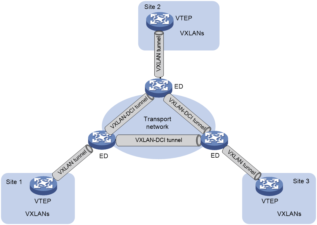
As shown in Figure 1, the VXLAN-DCI network contains edge devices (EDs) located at the edge of the transport network and VTEPs located at the data center sites. VXLAN tunnels are established between VTEPs and EDs, and VXLAN-DCI tunnels are established between EDs. VXLAN-DCI tunnels use VXLAN encapsulation. Each ED de-encapsulates received VXLAN packets and then re-encapsulates them based on the destination before forwarding them through a VXLAN or VXLAN-DCI tunnel.
Figure 1 VXLAN-DCI network model
Working mechanisms
In a VXLAN-DCI network, VTEPs use MAC address entries to perform Layer 2 forwarding for VXLANs, and EDs perform Layer 3 forwarding based on ARP or ND entries.
As shown in Figure 2, a VSI interface uses the same IP address to provide gateway services for a VXLAN on different EDs. Local proxy ARP or local ND proxy is enabled on the EDs.
Figure 2 VXLAN-DCI working mechanisms
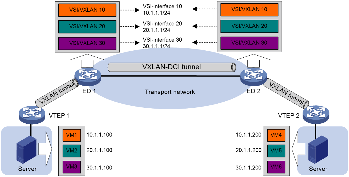
Intra-VXLAN traffic forwarding between sites
As shown in Figure 2, the network uses the following process to forward traffic in a VXLAN between sites (for example, from VM 1 to VM 4 in VXLAN 10):
1. VM 1 sends an ARP request to obtain the MAC address of VM 4.
2. VTEP 1 learns the MAC address of VM 1 and floods the ARP request in VXLAN 10.
3. ED 1 performs the following operations:
a. Removes the VXLAN encapsulation of the ARP request.
b. Creates an ARP entry for VM 1 and replies with the MAC address of VSI-interface 10 (the gateway interface for VXLAN 10). The ARP reply is sent to VTEP 1.
4. VTEP 1 removes the VXLAN encapsulation of the ARP reply, learns the MAC address of ED 1, and forwards the ARP reply to VM 1.
5. VM 1 creates an ARP entry for VM 4. The MAC address in the entry is the MAC address of VSI-interface 10 on ED 1.
6. ED 1 replaces the sender MAC address of the request with the MAC address of VSI-interface 10 on ED 1, and then floods the request to the remote EDs in VXLAN 10.
7. ED 2 performs the following operations:
a. Removes the VXLAN encapsulation of the ARP request.
b. Creates an ARP entry for VM 1. The entry contains VM 1's IP address (10.1.1.100), the MAC address of VSI-interface 10 on ED 1, and the incoming VXLAN-DCI tunnel interface.
c. Replaces the sender MAC address of the request with the MAC address of VSI-interface 10 on ED 2, and then floods the request on all VXLAN tunnels of VXLAN 10.
8. VTEP 2 removes the VXLAN encapsulation of the ARP request, learns the MAC address of ED 2, and floods the ARP request to the local site.
9. VM 4 creates an ARP entry for VM 1, and then sends a reply to VTEP 2. The MAC address in the ARP entry is the MAC address of VSI-interface 10 on ED 2.
10. VTEP 2 looks up the MAC address table and forwards the ARP reply to ED 2.
11. ED 2 performs the following operations:
a. Removes the VXLAN encapsulation of the ARP reply.
b. Creates an ARP entry for VM 4
c. Replaces the sender MAC address of the ARP reply with the MAC address of VSI-interface 10 on ED 2, and sends the reply to ED 1.
12. ED 1 performs the following operations:
a. Removes the VXLAN encapsulation of the ARP reply.
b. Creates an ARP entry for VM 4. The entry contains VM 4's IP address (10.1.1.200), the MAC address of VSI-interface 10 on ED 2, and the incoming VXLAN-DCI tunnel interface.
13. For subsequent traffic between VM 1 and VM 4, the VTEPs and EDs use their respective MAC address tables and ARP tables to make the forwarding decision.
Inter-VXLAN traffic forwarding between sites
As shown in Figure 2, the network uses the following process to forward traffic between VXLANs (for example, from VM 1 in VXLAN 10 to VM 5 in VXLAN 20):
1. VM 1 sends an ARP request to obtain the MAC address of the gateway at 10.1.1.1.
2. VTEP 1 learns the MAC address of VM 1 and floods the ARP request in VXLAN 10.
3. ED 1 performs the following operations:
a. Removes the VXLAN encapsulation of the ARP request.
b. Creates an ARP entry for VM 1 and replies with the MAC address of VSI-interface 10 (the gateway interface for VXLAN 10). The ARP reply is sent to VTEP 1.
4. VTEP 1 removes the VXLAN encapsulation of the ARP reply, learns the MAC address of ED 1, and forwards the ARP reply to VM 1.
5. VM 1 creates an ARP entry for the gateway and sends the packet destined for VM 5 to VTEP 1.
6. VTEP 1 looks up the MAC address table and forwards the packet to ED 1.
7. ED 1 performs the following operations:
a. Removes the VXLAN encapsulation of the packet and looks up the routing table based on the destination IP address.
b. Sends an ARP request to the local VTEP and remote ED of VXLAN 20 to obtain the MAC address of VM 5. In the ARP request, the sender IP address is 20.1.1.1, and the sender MAC address is the MAC address of VSI-interface 20 on ED 1.
8. ED 2 performs the following operations:
a. Removes the VXLAN encapsulation of the ARP request.
b. Replaces the sender MAC address of the request with the MAC address of VSI-interface 20 on ED 2, and then floods the request on all VXLAN tunnels of VXLAN 20.
9. VTEP 2 removes the VXLAN encapsulation of the ARP request, learns the MAC address of ED 2, and floods the ARP request to the local site.
10. VM 5 creates an ARP entry for ED 2 and sends a reply to VTEP 2. The MAC address in the ARP entry is the MAC address of VSI-interface 20 on ED 2.
11. VTEP 2 looks up the MAC address table and forwards the ARP reply to ED 2.
12. ED 2 performs the following operations:
a. Removes the VXLAN encapsulation of the ARP reply.
b. Creates an ARP entry for VM 5.
c. Sends a gratuitous ARP packet to ED 1. In the packet, the sender and target IP address is 20.1.1.200, and the sender MAC address is the MAC address of VSI-interface 20 on ED 2.
13. ED 1 performs the following operations:
a. Removes the VXLAN encapsulation of the packet.
b. Creates an ARP entry for VM 5. The entry contains VM 5's IP address (20.1.1.200), the MAC address of VSI-interface 20 on ED 2, and the incoming VXLAN-DCI tunnel interface.
14. For subsequent traffic between VM 1 and VM 5, the VTEPs and EDs use their respective MAC address tables and ARP tables to make the forwarding decision.
VXLAN-DCI tasks at a glance
To configure a VXLAN-DCI network, perform the following tasks:
· Configure routing protocols on the transport network for EDs to reach one another.
· Configure routing protocols on EDs and VTEPs for them to reach one another.
· Configure VXLANs on EDs and VTEPs, and set up VXLAN tunnels between EDs and VTEPs.
· Configure VXLAN-DCI on EDs, and set up VXLAN-DCI tunnels between EDs.
To configure VXLAN-DCI on an ED, perform the following tasks:
1. Creating a VXLAN on a VSI
For more information, see "Configuration basic VXLAN features."
2. Configuring a VXLAN-DCI tunnel
3. Assigning VXLAN-DCI tunnels to a VXLAN
4. Configuring a gateway interface on an ED
5. Configuring optional parameters for a VSI interface
For more information, see "Configuring VXLAN IP gateways."
6. Configuring VXLAN packet parameters
¡ Setting the destination UDP port number of VXLAN packets
For more information, see "Configuration basic VXLAN features."
¡ Configuring VXLAN packet check
For more information, see "Configuration basic VXLAN features."
7. Enabling packet statistics for a VSI
For more information, see "Configuration basic VXLAN features."
|
|
NOTE: This chapter covers only the VXLAN-DCI configuration tasks available on an ED. For more information about basic VXLAN configuration and VXLAN IP gateway configuration, see "Configuring basic VXLAN features" and "Configuring VXLAN IP gateways." |
Configuring a VXLAN-DCI tunnel
Restrictions and guidelines
You must specify the tunnel source and destination IP addresses when you manually set up a VXLAN-DCI tunnel between EDs. As a best practice, do not configure the same tunnel source and destination addresses for different VXLAN-DCI tunnels on an ED.
This task provides basic VXLAN-DCI tunnel configuration. For more information about tunnel interface configuration and commands, see Interface Configuration Guide and Interface Command Reference.
Procedure
1. Enter system view.
system-view
2. Create a VXLAN-DCI tunnel interface and enter tunnel interface view.
interface tunnel tunnel-number mode vxlan-dci
The endpoints of a tunnel must use the same tunnel mode.
3. Specify a source address for the tunnel. Choose one of the following tasks:
¡ Specify a source IP address.
source ipv4-address | interface-type interface-number }
The specified IP address is used as the source IP address in the outer IP header of tunneled VXLAN packets.
¡ Specify a source interface.
source interface-type interface-number
The primary IP address is used as the source IP address in the outer IP header of tunneled VXLAN packets.
By default, no source address is specified for a tunnel.
4. Specify a destination IP address for the tunnel.
destination ipv4-address
By default, no destination IP address is specified for a tunnel.
Specify the remote ED's IP address. This IP address will be the destination IP address in the outer IP header of tunneled VXLAN packets.
Assigning VXLAN-DCI tunnels to a VXLAN
About this task
To provide connectivity for a VXLAN between two EDs, you must assign the VXLAN-DCI tunnel between the EDs to the VXLAN.
You can assign multiple VXLAN-DCI tunnels to a VXLAN, and configure a VXLAN-DCI tunnel to trunk multiple VXLANs. EDs use the VXLAN ID in VXLAN packets to identify the VXLAN. For a unicast-mode VXLAN, the system floods unknown unicast, multicast, and broadcast traffic to each VXLAN-DCI tunnel associated with the VXLAN.
Restrictions and guidelines
For full connectivity in the VXLAN, make sure the VXLAN contains the VXLAN-DCI tunnel between each pair of EDs in the VXLAN.
Procedure
1. Enter system view.
system-view
2. Enter VSI view.
vsi vsi-name
3. Enter VXLAN view.
vxlan vxlan-id
4. Assign VXLAN-DCI tunnels to the VXLAN.
tunnel { tunnel-number | all }
By default, a VXLAN does not contain any VXLAN-DCI tunnels.
For more information about this command, see VXLAN Command Reference.
Configuring a gateway interface on an ED
1. Enter system view.
system-view
2. Create a VSI interface and enter VSI interface view.
interface vsi-interface vsi-interface-id
3. Assign an IP address to the VSI interface.
IPv4:
ip address ip-address { mask | mask-length } [ sub ]
IPv6:
See IPv6 basics in Layer 3—IP Services Configuration Guide.
By default, no IP address is assigned to a VSI interface.
4. Specify the VSI interface as a distributed gateway.
distributed-gateway local
By default, a VSI interface is not a distributed gateway.
5. Enable local proxy ARP or local ND proxy.
IPv4:
local-proxy-arp enable [ ip-range startIP to endIP ]
By default, local proxy ARP is disabled.
For more information about this command, see proxy ARP commands in Layer 3—IP Services Command Reference.
IPv6:
local-proxy-nd enable
By default, local ND proxy is disabled.
For more information about this command, see IPv6 neighbor discovery commands in Layer 3—IP Services Command Reference.
6. Bring up the VSI interface.
undo shutdown
By default, a VSI interface is up.
7. Return to system view.
quit
8. Enter VSI view.
vsi vsi-name
9. Specify the VSI interface as the gateway interface for the VSI.
gateway vsi-interface vsi-interface-id
By default, no gateway interface is specified for a VSI.
Verifying and maintaining VXLAN-DCI
Verifying VSI configuration and running status
To display information about VSIs, execute the following command in any view:
display l2vpn vsi [ name vsi-name ] [ verbose ]
To clear packet statistics on VSIs, execute the following command in user view:
reset l2vpn statistics vsi [ name vsi-name ]
Verifying tunnel configuration and running status
Perform display tasks in any view.
· Display information about tunnel interfaces.
display interface [ tunnel [ number ] ] [ brief [ description | down ] ]
For more information about this command, see tunnel interface commands in Interface Command Reference.
· Display VXLAN-DCI tunnel information for VXLANs.
display vxlan tunnel [ vxlan-id vxlan-id ]
VXLAN-DCI configuration examples
Example: Configuring a basic VXLAN-DCI network
Network configuration
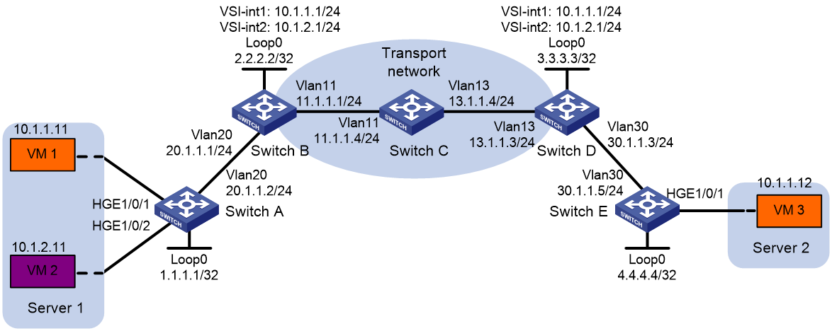
As shown in Figure 3:
· Configure VXLAN 10 and VXLAN 20 as unicast-mode VXLANs on Switch A, Switch B, Switch D, and Switch E to provide connectivity for the VMs across the data center sites.
· Configure Switch A and Switch E as VTEPs, and Switch B and Switch D as EDs.
· Manually establish VXLAN tunnels and VXLAN-DCI tunnels, and assign the tunnels to the VXLANs.
Procedure
|
|
IMPORTANT: By default, interfaces on the device are disabled (in ADM or Administratively Down state). To have an interface operate, you must use the undo shutdown command to enable that interface. By default, interfaces on the device operate in Layer 3 mode. In this example, you must use the port link-mode command to configure the interfaces that host Ethernet service instances to operate in Layer 2 mode. |
1. Configure IP addresses and unicast routing settings:
# Assign IP addresses to interfaces, as shown in Figure 3. (Details not shown.)
# Configure OSPF on Switches A through E. (Details not shown.)
# Configure OSPF to advertise routes to networks 10.1.1.0/24 and 10.1.2.0/24 on Switch B and Switch D. (Details not shown.)
2. Configure Switch A:
# Enable L2VPN.
<SwitchA> system-view
[SwitchA] l2vpn enable
# Create VSI vpna and VXLAN 10.
[SwitchA] vsi vpna
[SwitchA-vsi-vpna] vxlan 10
[SwitchA-vsi-vpna-vxlan-10] quit
[SwitchA-vsi-vpna] quit
# Create VSI vpnb and VXLAN 20.
[SwitchA] vsi vpnb
[SwitchA-vsi-vpnb] vxlan 20
[SwitchA-vsi-vpnb-vxlan-20] quit
[SwitchA-vsi-vpnb] quit
# Assign an IP address to Loopback 0. The IP address will be used as the source IP address of the VXLAN tunnel to Switch B.
[SwitchA] interface loopback 0
[SwitchA-Loopback0] ip address 1.1.1.1 255.255.255.255
[SwitchA-Loopback0] quit
# Create a VXLAN tunnel to Switch B. The tunnel interface name is Tunnel 1.
[SwitchA] interface tunnel 1 mode vxlan
[SwitchA-Tunnel1] source 1.1.1.1
[SwitchA-Tunnel1] destination 2.2.2.2
[SwitchA-Tunnel1] quit
# Assign Tunnel 1 to VXLAN 10.
[SwitchA] vsi vpna
[SwitchA-vsi-vpna] vxlan 10
[SwitchA-vsi-vpna-vxlan-10] tunnel 1
[SwitchA-vsi-vpna-vxlan-10] quit
[SwitchA-vsi-vpna] quit
# Assign Tunnel 1 to VXLAN 20.
[SwitchA] vsi vpnb
[SwitchA-vsi-vpnb] vxlan 20
[SwitchA-vsi-vpnb-vxlan-20] tunnel 1
[SwitchA-vsi-vpnb-vxlan-20] quit
[SwitchA-vsi-vpnb] quit
# On HundredGigE 1/0/1, create Ethernet service instance 1000 to match VLAN 100.
[SwitchA] interface hundredgige 1/0/1
[SwitchA-HundredGigE1/0/1] port link-type trunk
[SwitchA-HundredGigE1/0/1] port trunk permit vlan 100
[SwitchA-HundredGigE1/0/1] service-instance 1000
[SwitchA-HundredGigE1/0/1-srv1000] encapsulation s-vid 100
# Map Ethernet service instance 1000 on HundredGigE 1/0/1 to VSI vpna.
[SwitchA-HundredGigE1/0/1-srv1000] xconnect vsi vpna
[SwitchA-HundredGigE1/0/1-srv1000] quit
[SwitchA-HundredGigE1/0/1] quit
# On HundredGigE 1/0/2, create Ethernet service instance 1000 to match VLAN 200.
[SwitchA] interface hundredgige 1/0/2
[SwitchA-HundredGigE1/0/2] port link-type trunk
[SwitchA-HundredGigE1/0/2] port trunk permit vlan 200
[SwitchA-HundredGigE1/0/2] service-instance 1000
[SwitchA-HundredGigE1/0/2-srv1000] encapsulation s-vid 200
# Map Ethernet service instance 1000 on HundredGigE 1/0/2 to VSI vpnb.
[SwitchA-HundredGigE1/0/2-srv1000] xconnect vsi vpnb
[SwitchA-HundredGigE1/0/2-srv1000] quit
[SwitchA-HundredGigE1/0/2] quit
3. Configure Switch B:
# Enable L2VPN.
<SwitchB> system-view
[SwitchB] l2vpn enable
# Create VSI vpna and VXLAN 10.
[SwitchB] vsi vpna
[SwitchB-vsi-vpna] vxlan 10
[SwitchB-vsi-vpna-vxlan-10] quit
[SwitchB-vsi-vpna] quit
# Create VSI vpnb and VXLAN 20.
[SwitchB] vsi vpnb
[SwitchB-vsi-vpnb] vxlan 20
[SwitchB-vsi-vpnb-vxlan-20] quit
[SwitchB-vsi-vpnb] quit
# Assign an IP address to Loopback 0. The IP address will be used as the source IP address of the VXLAN tunnel to Switch A and the VXLAN-DCI tunnel to Switch D.
[SwitchB] interface loopback 0
[SwitchB-Loopback0] ip address 2.2.2.2 255.255.255.255
[SwitchB-Loopback0] quit
# Create a VXLAN tunnel to Switch A. The tunnel interface name is Tunnel 1.
[SwitchB] interface tunnel 1 mode vxlan
[SwitchB-Tunnel1] source 2.2.2.2
[SwitchB-Tunnel1] destination 1.1.1.1
[SwitchB-Tunnel1] quit
# Create a VXLAN-DCI tunnel to Switch D. The tunnel interface name is Tunnel 2.
[SwitchB] interface tunnel 2 mode vxlan-dci
[SwitchB-Tunnel2] source 2.2.2.2
[SwitchB-Tunnel2] destination 3.3.3.3
[SwitchB-Tunnel2] quit
# Assign Tunnel 1 and Tunnel 2 to VXLAN 10.
[SwitchB] vsi vpna
[SwitchB-vsi-vpna] vxlan 10
[SwitchB-vsi-vpna-vxlan-10] tunnel 1
[SwitchB-vsi-vpna-vxlan-10] tunnel 2
[SwitchB-vsi-vpna-vxlan-10] quit
[SwitchB-vsi-vpna] quit
# Assign Tunnel 1 and Tunnel 2 to VXLAN 20.
[SwitchB] vsi vpnb
[SwitchB-vsi-vpnb] vxlan 20
[SwitchB-vsi-vpnb-vxlan-20] tunnel 1
[SwitchB-vsi-vpnb-vxlan-20] tunnel 2
[SwitchB-vsi-vpnb-vxlan-20] quit
[SwitchB-vsi-vpnb] quit
# Create VSI-interface 1 and assign the interface an IP address. The IP address will be used as the gateway address for VXLAN 10.
[SwitchB] interface vsi-interface 1
[SwitchB-Vsi-interface1] ip address 10.1.1.1 255.255.255.0
# Specify VSI-interface 1 as a distributed gateway and enable local proxy ARP on the interface.
[SwitchB-Vsi-interface1] distributed-gateway local
[SwitchB-Vsi-interface1] local-proxy-arp enable
[SwitchB-Vsi-interface1] quit
# Create VSI-interface 2 and assign the interface an IP address. The IP address will be used as the gateway address for VXLAN 20.
[SwitchB] interface vsi-interface 2
[SwitchB-Vsi-interface2] ip address 10.1.2.1 255.255.255.0
# Specify VSI-interface 2 as a distributed gateway and enable local proxy ARP on the interface.
[SwitchB-Vsi-interface2] distributed-gateway local
[SwitchB-Vsi-interface2] local-proxy-arp enable
[SwitchB-Vsi-interface2] quit
# Enable dynamic ARP entry synchronization for distributed VXLAN IP gateways.
[SwitchB] arp distributed-gateway dynamic-entry synchronize
# Specify VSI-interface 1 as the gateway interface for VSI vpna.
[SwitchB] vsi vpna
[SwitchB-vsi-vpna] gateway vsi-interface 1
[SwitchB-vsi-vpna] quit
# Specify VSI-interface 2 as the gateway interface for VSI vpnb.
[SwitchB] vsi vpnb
[SwitchB-vsi-vpnb] gateway vsi-interface 2
[SwitchB-vsi-vpnb] quit
4. Configure Switch D:
# Enable L2VPN.
<SwitchD> system-view
[SwitchD] l2vpn enable
# Create VSI vpna and VXLAN 10.
[SwitchD] vsi vpna
[SwitchD-vsi-vpna] vxlan 10
[SwitchD-vsi-vpna-vxlan-10] quit
[SwitchD-vsi-vpna] quit
# Create VSI vpnb and VXLAN 20.
[SwitchD] vsi vpnb
[SwitchD-vsi-vpnb] vxlan 20
[SwitchD-vsi-vpnb-vxlan-20] quit
[SwitchD-vsi-vpnb] quit
# Assign an IP address to Loopback 0. The IP address will be used as the source IP address of the VXLAN-DCI tunnel to Switch B and the VXLAN tunnel to Switch E.
[SwitchD] interface loopback 0
[SwitchD-Loopback0] ip address 3.3.3.3 255.255.255.255
[SwitchD-Loopback0] quit
# Create a VXLAN tunnel to Switch E. The tunnel interface name is Tunnel 1.
[SwitchD] interface tunnel 1 mode vxlan
[SwitchD-Tunnel1] source 3.3.3.3
[SwitchD-Tunnel1] destination 4.4.4.4
[SwitchD-Tunnel1] quit
# Create a VXLAN-DCI tunnel to Switch B. The tunnel interface name is Tunnel 2.
[SwitchD] interface tunnel 2 mode vxlan-dci
[SwitchD-Tunnel2] source 3.3.3.3
[SwitchD-Tunnel2] destination 2.2.2.2
[SwitchD-Tunnel2] quit
#Assign Tunnel 1 and Tunnel 2 to VXLAN 10.
[SwitchD] vsi vpna
[SwitchD-vsi-vpna] vxlan 10
[SwitchD-vsi-vpna-vxlan-10] tunnel 1
[SwitchD-vsi-vpna-vxlan-10] tunnel 2
[SwitchD-vsi-vpna-vxlan-10] quit
[SwitchD-vsi-vpna] quit
# Assign Tunnel 2 to VXLAN 20.
[SwitchD] vsi vpnb
[SwitchD-vsi-vpnb] vxlan 20
[SwitchD-vsi-vpnb-vxlan-20] tunnel 2
[SwitchD-vsi-vpnb-vxlan-20] quit
[SwitchD-vsi-vpnb] quit
# Create VSI-interface 1 and assign the interface an IP address. The IP address will be used as the gateway address for VXLAN 10.
[SwitchD] interface vsi-interface 1
[SwitchD-Vsi-interface1] ip address 10.1.1.1 255.255.255.0
# Specify VSI-interface 1 as a distributed gateway and enable local proxy ARP on the interface.
[SwitchD-Vsi-interface1] distributed-gateway local
[SwitchD-Vsi-interface1] local-proxy-arp enable
[SwitchD-Vsi-interface1] quit
# Create VSI-interface 2 and assign the interface an IP address. The IP address will be used as the gateway address for VXLAN 20.
[SwitchD] interface vsi-interface 2
[SwitchD-Vsi-interface2] ip address 10.1.2.1 255.255.255.0
# Specify VSI-interface 2 as a distributed gateway and enable local proxy ARP on the interface.
[SwitchD-Vsi-interface2] distributed-gateway local
[SwitchD-Vsi-interface2] local-proxy-arp enable
[SwitchD-Vsi-interface2] quit
# Enable dynamic ARP entry synchronization for distributed VXLAN IP gateways.
[SwitchD] arp distributed-gateway dynamic-entry synchronize
# Specify VSI-interface 1 as the gateway interface for VSI vpna.
[SwitchD] vsi vpna
[SwitchD-vsi-vpna] gateway vsi-interface 1
[SwitchD-vsi-vpna] quit
# Specify VSI-interface 2 as the gateway interface for VSI vpnb.
[SwitchD] vsi vpnb
[SwitchD-vsi-vpnb] gateway vsi-interface 2
[SwitchD-vsi-vpnb] quit
5. Configure Switch E:
# Enable L2VPN.
<SwitchE> system-view
[SwitchE] l2vpn enable
# Create VSI vpna and VXLAN 10.
[SwitchE] vsi vpna
[SwitchE-vsi-vpna] vxlan 10
[SwitchE-vsi-vpna-vxlan-10] quit
[SwitchE-vsi-vpna] quit
# Assign an IP address to Loopback 0. The IP address will be used as the source IP address of the VXLAN tunnel to Switch D.
[SwitchE] interface loopback 0
[SwitchE-Loopback0] ip address 4.4.4.4 255.255.255.255
[SwitchE-Loopback0] quit
# Create a VXLAN tunnel to Switch D. The tunnel interface name is Tunnel 1.
[SwitchE] interface tunnel 1 mode vxlan
[SwitchE-Tunnel1] source 4.4.4.4
[SwitchE-Tunnel1] destination 3.3.3.3
[SwitchE-Tunnel1] quit
# Assign Tunnel 1 to VXLAN 10.
[SwitchE] vsi vpna
[SwitchE-vsi-vpna] vxlan 10
[SwitchE-vsi-vpna-vxlan-10] tunnel 1
[SwitchE-vsi-vpna-vxlan-10] quit
[SwitchE-vsi-vpna] quit
# On HundredGigE 1/0/1, create Ethernet service instance 1000 to match VLAN 100.
[SwitchE] interface hundredgige 1/0/1
[SwitchE-HundredGigE1/0/1] port link-type trunk
[SwitchE-HundredGigE1/0/1] port trunk permit vlan 100
[SwitchE-HundredGigE1/0/1] service-instance 1000
[SwitchE-HundredGigE1/0/1-srv1000] encapsulation s-vid 100
# Map Ethernet service instance 1000 to VSI vpna.
[SwitchE-HundredGigE1/0/1-srv1000] xconnect vsi vpna
[SwitchE-HundredGigE1/0/1-srv1000] quit
[SwitchE-HundredGigE1/0/1] quit
Verifying the configuration
1. Verify the VXLAN-DCI settings on the EDs. This example uses Switch B.
# Verify that the VXLAN and VXLAN-DCI tunnel interfaces are up on Switch B.
[SwitchB] display interface tunnel
Tunnel1
Current state: UP
Line protocol state: UP
Description: Tunnel1 Interface
Bandwidth: 64 kbps
Maximum transmission unit: 64000
Internet protocol processing: Disabled
Last clearing of counters: Never
Tunnel source 2.2.2.2, destination 1.1.1.1
Tunnel protocol/transport UDP_VXLAN/IP
Last 300 seconds input rate: 0 bytes/sec, 0 bits/sec, 0 packets/sec
Last 300 seconds output rate: 0 bytes/sec, 0 bits/sec, 0 packets/sec
Input: 0 packets, 0 bytes, 0 drops
Output: 0 packets, 0 bytes, 0 drops
Tunnel2
Current state: UP
Line protocol state: UP
Description: Tunnel2 Interface
Bandwidth: 64 kbps
Maximum transmission unit: 64000
Internet protocol processing: Disabled
Last clearing of counters: Never
Tunnel source 2.2.2.2, destination 3.3.3.3
Tunnel protocol/transport UDP_VXLAN_DCI/IP
Last 300 seconds input rate: 0 bytes/sec, 0 bits/sec, 0 packets/sec
Last 300 seconds output rate: 0 bytes/sec, 0 bits/sec, 0 packets/sec
Input: 0 packets, 0 bytes, 0 drops
Output: 0 packets, 0 bytes, 0 drops
# Verify that VSI-interface 1 and VSI-interface 2 are up.
[SwitchB] display interface vsi-interface
Vsi-interface1
Current state: UP
Line protocol state: UP
Description: Vsi-interface1 Interface
Bandwidth: 1000000 kbps
Maximum transmission unit: 1444
Internet address: 10.1.1.1/24 (primary)
IP packet frame type:PKTFMT_ETHNT_2, hardware address: 0011-2200-0102
IPv6 packet frame type:PKTFMT_ETHNT_2, hardware address: 0011-2200-0102
Physical: Unknown, baudrate: 1000000 kbps
Last clearing of counters: Never
Last 300 seconds input rate: 0 bytes/sec, 0 bits/sec, 0 packets/sec
Last 300 seconds output rate: 0 bytes/sec, 0 bits/sec, 0 packets/sec
Input: 0 packets, 0 bytes, 0 drops
Output: 0 packets, 0 bytes, 0 drops
Vsi-interface2
Current state: UP
Line protocol state: UP
Description: Vsi-interface2 Interface
Bandwidth: 1000000 kbps
Maximum transmission unit: 1444
Internet address: 10.1.2.1/24 (primary)
IP packet frame type:PKTFMT_ETHNT_2, hardware address: 0011-3300-0102
IPv6 packet frame type:PKTFMT_ETHNT_2, hardware address: 0011-3300-0102
Physical: Unknown, baudrate: 1000000 kbps
Last clearing of counters: Never
Last 300 seconds input rate: 0 bytes/sec, 0 bits/sec, 0 packets/sec
Last 300 seconds output rate: 0 bytes/sec, 0 bits/sec, 0 packets/sec
Input: 0 packets, 0 bytes, 0 drops
Output: 0 packets, 0 bytes, 0 drops
# Verify that the VXLAN and VXLAN-DCI tunnels have been assigned to VXLAN 10 and VXLAN 20, and the VSI interfaces are the gateway interfaces for their respective VSIs.
[SwitchB] display l2vpn vsi verbose
VSI Name: vpna
VSI Index : 0
VSI State : Up
MTU : -
Diffserv Mode : -
Bandwidth : Unlimited
Broadcast Restrain : Unlimited
Multicast Restrain : Unlimited
Unknown Unicast Restrain: Unlimited
MAC Learning : Enabled
MAC Table Limit : -
MAC Learning rate : -
Drop Unknown : -
PW Redundancy Mode : Slave
Flooding : Enabled
ESI : 0000.0000.0000.0000.0000
Redundancy Mode : All-active
Statistics : Disabled
Gateway interface : VSI-interface 1
VXLAN ID : 10
EVPN Encapsulation : VXLAN
Tunnels:
Tunnel Name Link ID State Type Flood proxy
Tunnel1 0x5000001 Up Manual Disabled
Tunnel2 0x5000002 Up Manual Disabled
VSI Name: vpnb
VSI Index : 1
VSI State : Up
MTU : -
Diffserv Mode : -
Bandwidth : Unlimited
Broadcast Restrain : Unlimited
Multicast Restrain : Unlimited
Unknown Unicast Restrain: Unlimited
MAC Learning : Enabled
MAC Table Limit : -
MAC Learning rate : -
Drop Unknown : -
PW Redundancy Mode : Slave
Flooding : Enabled
ESI : 0000.0000.0000.0000.0000
Redundancy Mode : All-active
Statistics : Disabled
Gateway interface : VSI-interface 2
VXLAN ID : 20
EVPN Encapsulation : VXLAN
Tunnels:
Tunnel Name Link ID State Type Flood proxy
Tunnel1 0x5000001 Up Manual Disabled
Tunnel2 0x5000002 Up Manual Disabled
# Verify that Switch B has created ARP entries for the VMs.
[SwitchB] display arp
Type: S-Static D-Dynamic O-Openflow R-Rule I-Invalid
IP address MAC address VLAN/VSI name Interface Aging Type
11.1.1.4 000c-29c1-5e46 -- Vlan11 19 D
10.1.1.11 0cda-41b5-cf09 vpna Tunnel1 20 D
10.1.1.12 0011-4400-0102 vpna Tunnel2 20 D
10.1.2.11 0cda-41b5-cf89 vpnb Tunnel1 20 D
2. Verify that VM 1, VM 2, and VM 3 can ping each other. (Details not shown.)
