- Table of Contents
- Related Documents
-
01-Hardware Information and Specifications.htm
Product models and technical specifications
Removable components and compatibility matrixes
2.5G/1000/100BASE-T Ethernet port
10/100/1000BASE-T Ethernet port
10/100/1000BASE-T autosensing Ethernet port LED
2.5G/1000/100BASE-T autosensing Ethernet port LED
SFP port LED (S5570S-36F-EI switch)
Product models and technical specifications
Unless otherwise stated, power supplies and power modules are used interchangeably in this document.
Product models
Table 1 Switch series and models
|
Model |
Product code (PID) |
|
|
S5170-EI switch series |
S5170-28S-EI |
LS-5170-28S-EI |
|
LS-5170-28S-EI-GL |
||
|
S5170-54S-EI |
LS-5170-54S-EI |
|
|
LS-5170-54S-EI-GL |
||
|
S5170-54S-EI-DP |
LS-5170-54S-EI-DP |
|
|
S5170-28S-HPWR-EI |
LS-5170-28S-HPWR-EI |
|
|
LS-5170-28S-HPWR-EI-GL |
||
|
S5170-54S-PWR-EI |
LS-5170-54S-PWR-EI |
|
|
LS-5170-54S-PWR-EI-GL |
||
|
S5170-36F-EI |
LS-5170-36F-EI |
|
|
S5170-36F-EI-DP |
LS-5170-36F-EI-DP |
|
|
S5570S-EI switch series |
S5570S-28S-EI |
LS-5570S-28S-EI |
|
LS-5570S-28S-EI-GL |
||
|
S5570S-54S-EI |
LS-5570S-54S-EI |
|
|
LS-5570S-54S-EI-GL |
||
|
S5570S-28S-HPWR-EI |
LS-5570S-28S-HPWR-EI |
|
|
S5570S-28S-HPWR-EI-A |
LS-5570S-28S-HPWR-EI-A |
|
|
LS-5570S-28S-HPWR-EI-A-GL |
||
|
S5570S-54S-PWR-EI |
LS-5570S-54S-PWR-EI |
|
|
S5570S-54S-PWR-EI-A |
LS-5570S-54S-PWR-EI-A |
|
|
LS-5570S-54S-PWR-EI-A-GL |
||
|
S5570S-36F-EI |
LS-5570S-36F-EI |
|
|
LS-5570S-36F-EI-GL |
||
|
S5570S-54F-EI |
LS-5570S-54F-EI |
|
|
LS-5570S-54F-EI-GL |
||
|
S5570S-30MS-UPWR-EI |
LS-5570S-30MS-UPWR-EI |
|
|
NOTE: · Switches of the same model but different PIDs might differ in hardware and software features. You can view the PID of a switch on the label located on its rear panel or top panel. · The available chassis models and accessories vary by country and region. This document describes only the preceding models. For the chassis models and accessories available in your country or region, contact the local H3C marketing personnel. |
Technical specifications
S5170-EI switch series
Table 2 Technical specifications for non-PoE switch models (1)
|
Item |
S5170-28S-EI |
S5170-54S-EI |
S5170-36F-EI |
|
Dimensions (H × W × D) |
43.6 × 440 × 160 mm (1.72 × 17.32 × 6.30 in) |
43.6 × 440 × 260 mm (1.72 × 17.32 × 10.24 in) |
43.6 × 440 × 260 mm (1.72 × 17.32 × 10.24 in) |
|
Weight |
≤ 2.2 kg (4.85 lb) |
≤ 4.0 kg (8.82 lb) |
≤ 3.5 kg (7.72 lb) |
|
Console port |
1 × serial console port |
||
|
SFP port |
N/A |
N/A |
24 |
|
SFP+ port |
4 |
6 |
4 |
|
10/100/1000BASE-T autosensing Ethernet port |
24 |
48 |
8 |
|
Input voltage |
AC input: · Rated voltage range: 100 VAC to 240 VAC @ 50 Hz or 60 Hz · Max voltage range: 90 VAC to 264 VAC @ 47 Hz to 63 Hz |
AC input: · Rated voltage range: 100 VAC to 240 VAC @ 50 Hz or 60 Hz · Max voltage range: 85 VAC to 264 VAC @ 47 Hz to 63 Hz |
AC input: · Rated voltage range: 100 VAC to 240 VAC @ 50 Hz or 60 Hz · Max voltage range: 90 VAC to 264 VAC @ 47 Hz to 63 Hz |
|
Minimum power consumption |
17 W |
19 W |
27 W |
|
Maximum power consumption |
37 W |
53 W |
54 W |
|
Chassis leakage current compliance |
UL 62368-1/EN 62368-1/IEC 62368-1/UL 60950-1/EN 60950-1/IEC 60950-1/GB4943.1 |
||
|
Melting current of power supply fuse |
2 A/250 V |
3.15 A/250 V |
3.15 A/250 V |
|
Operating temperature |
–5°C to +45°C (23°F to 113°F) |
||
|
Operating humidity |
5% RH to 95% RH, noncondensing |
||
|
Fire resistance compliance |
UL 62368-1/EN 62368-1/IEC 62368-1/UL 60950-1/EN 60950-1/IEC 60950-1/GB4943.1 |
||
Table 3 Technical specifications for non-PoE switch models (2)
|
Item |
S5170-54S-EI-DP |
S5170-36F-EI-DP |
|
Dimensions (H × W × D) |
43.6 × 440 × 320 mm (1.72 × 17.32 × 12.60 in) |
43.6 × 440 × 260 mm (1.72 × 17.32 × 10.24 in) |
|
Weight |
≤ 4.3 kg (9.48 lb) |
≤ 3.6 kg (7.94 lb) |
|
Console port |
1 × serial console port |
|
|
SFP port |
N/A |
24 |
|
SFP+ port |
6 |
4 |
|
10/100/1000BASE-T autosensing Ethernet port |
48 |
8 |
|
Input voltage |
AC input: · Rated voltage range: 100 VAC to 240 VAC @ 50 Hz or 60 Hz · Max voltage range: 90 VAC to 264 VAC @ 47 Hz to 63 Hz |
|
|
Minimum power consumption |
· Single AC input: 23.5 W · Dual AC inputs: 24 W |
· Single AC input: 24.5 W · Dual AC inputs: 25 W |
|
Maximum power consumption |
· Single AC input: 61.5 W · Dual AC inputs: 62 W |
· Single AC input: 60.5 W · Dual AC inputs: 61 W |
|
Chassis leakage current compliance |
UL62368-1/EN62368-1/IEC62368-1/UL60950-1/EN60950-1/IEC60950-1/GB4943.1 |
|
|
Melting current of power supply fuse |
3.15 A/250 V |
|
|
Operating temperature |
–5°C to +45°C (23°F to 113°F) |
|
|
Operating humidity |
5% RH to 95% RH, noncondensing |
|
|
Fire resistance compliance |
UL62368-1/EN62368-1/IEC62368-1/UL60950-1/EN60950-1/IEC60950-1/GB4943.1 |
|
Table 4 Technical specifications for PoE switch models
|
Item |
S5170-28S-HPWR-EI |
S5170-54S-PWR-EI |
|
Dimensions (H × W × D) |
43.6 × 440 × 320 mm (1.72 × 17.32 × 12.60 in) |
43.6 × 440 × 320 mm (1.72 × 17.32 × 12.60 in) |
|
Weight |
≤ 5.0 kg (11.02 lb) |
≤ 5.5 kg (12.13 lb) |
|
Console port |
1 × serial console port |
|
|
SFP+ port |
4 |
6 |
|
10/100/1000BASE-T autosensing Ethernet port |
24 |
48 |
|
Input voltage |
AC input: · Rated voltage range: 100 VAC to 240 VAC @ 50 Hz or 60 Hz · Max voltage range: 90 VAC to 264 VAC @ 47 Hz to 63 Hz |
|
|
PoE power capacity |
· Total PoE power capacity: 370 W · Max PoE power capacity per port ¡ In R1111 and earlier: 30 W ¡ In R1112 and later: 35 W |
|
|
Minimum power consumption |
24 W |
30 W |
|
Maximum power consumption (including PoE power consumption) |
460 W |
470 W |
|
Power efficiency |
80 plus gold certified |
80 plus gold certified |
|
Chassis leakage current compliance |
UL 62368-1/EN 62368-1/IEC 62368-1/UL 60950-1/EN 60950-1/IEC 60950-1/GB4943.1 |
|
|
Melting current of power supply fuse |
10 A/250 V |
|
|
Operating temperature |
–5°C to +45°C (23°F to 113°F) |
|
|
Operating humidity |
5% RH to 95% RH, noncondensing |
|
|
Fire resistance compliance |
UL 62368-1/EN 62368-1/IEC 62368-1/UL 60950-1/EN 60950-1/IEC 60950-1/GB4943.1 |
|
S5570S-EI switch series
Table 5 Technical specifications for non-PoE switch models
|
Item |
S5570S-28S-EI |
S5570S-54S-EI |
S5570S-36F-EI |
S5570S-54F-EI |
|
Dimensions (H × W × D) |
43.6 × 440 × 360 mm (1.72 × 17.32 × 14.17 in) |
43.6 × 440 × 360 mm (1.72 × 17.32 × 14.17 in) |
43.6 × 440 × 360 mm (1.72 × 17.32 × 14.17 in) |
43.6 × 440 × 360 mm (1.72 × 17.32 × 14.17 in) |
|
Weight |
≤ 5.6 kg (12.35 lb) |
≤ 6.0 kg (13.23 lb) |
≤ 4.5 kg (9.92 lb) |
≤ 4.5 kg (9.92 lb) |
|
Console port |
1 × serial console port |
|||
|
Management Ethernet port |
N/A |
N/A |
N/A |
1 |
|
SFP port |
N/A |
N/A |
24 |
48 |
|
SFP+ port |
4 |
6 |
4 |
6 |
|
10/100/1000BASE-T autosensing Ethernet port |
24 |
48 |
8 |
N/A |
|
Power supply slot |
2, on the rear panel |
|||
|
Input voltage |
· CA-70A12 power supply: ¡ Rated voltage range: 100 VAC to 240 VAC @ 50 Hz or 60 Hz ¡ Max voltage range: 90 VAC to 290 VAC @ 47 Hz to 63 Hz · PSR75-12A power module: ¡ Rated voltage range: 100 VAC to 240 VAC @ 50 Hz or 60 Hz ¡ Max voltage range: 90 VAC to 290 VAC @ 47 Hz to 63 Hz · PSR150-D1 power supply: ¡ Rated voltage range: –48 VDC to –60 VDC ¡ Max voltage range: –36 VDC to –72 VDC ¡ DC power source for the PSR150-D1 power supply: –48 VDC power source in the equipment room or an RPS (H3C RPS800-A or RPS1600-A) |
|||
|
Minimum power consumption |
· Single AC input: 16 W · Dual AC inputs: 18 W · Single DC input: 22 W · Dual DC inputs: 27 W |
· Single AC input: 18 W · Dual AC inputs: 23 W · Single DC input: 23 W · Dual DC inputs: 29 W |
· Single AC input: 29 W · Dual AC inputs: 35 W · Single DC input: 30 W · Dual DC inputs: 35 W |
· Single AC input: 36 W · Dual AC inputs: 43 W · Single DC input: 38 W · Dual DC inputs: 43 W |
|
Maximum power consumption |
· Single AC input: 37 W · Dual AC inputs: 39 W · Single DC input: 41 W · Dual DC inputs: 45 W |
· Single AC input: 55 W · Dual AC inputs: 57 W · Single DC input: 56 W · Dual DC inputs: 61 W |
· Single AC input: 52 W · Dual AC inputs: 58 W · Single DC input: 54 W · Dual DC inputs: 60 W |
· Single AC input: 77 W · Dual AC inputs: 80 W · Single DC input: 77 W · Dual DC inputs: 84 W |
|
Chassis leakage current compliance |
UL 62368-1/EN 62368-1/IEC 62368-1/UL 60950-1/EN 60950-1/IEC 60950-1/GB4943.1 |
|||
|
Melting current of power supply fuse |
· CA-70A12 power supply: 10 A/250 V · PSR75-12A power module: 3.15 A/250 V · PSR150-D1 power supply: 8 A/250 V |
|||
|
Operating temperature |
–5°C to +45°C (23°F to 113°F) |
|||
|
Operating humidity |
5% RH to 95% RH, noncondensing |
|||
|
Fire resistance compliance |
UL 62368-1/EN 62368-1/IEC 62368-1/UL 60950-1/EN 60950-1/IEC 60950-1/GB4943.1 |
|||
Table 6 Technical specifications for PoE switch models (1)
|
Item |
S5570S-28S-HPWR-EI |
S5570S-54S-PWR-EI |
S5570S-30MS-UPWR-EI |
|
Dimensions (H × W × D) |
43.6 × 440 × 460 mm (1.72 × 17.32 × 18.11 in) |
43.6 × 440 × 460 mm (1.72 × 17.32 × 18.11 in) |
43.6 × 440 × 460 mm (1.72 × 17.32 × 18.11 in) |
|
Weight |
≤ 5.5 kg (12.13 lb) |
≤ 6.0 kg (13.23 lb) |
≤ 8.5 kg (18.74 lb) |
|
Console port |
1 × serial console port |
||
|
SFP+ port |
4 |
6 |
6 |
|
2.5G/1000/100BASE-T-PoE++ autosensing Ethernet port |
N/A |
N/A |
24 |
|
10/100/1000BASE-T autosensing Ethernet port |
24 |
48 |
N/A |
|
Power supply slot |
2, on the rear panel |
||
|
Input voltage |
· PSR180-56A power module (S5570S-28S-HPWR-EI and S5570S-54S-PWR-EI): ¡ Rated voltage range for AC input: 100 VAC to 240 VAC @ 50 Hz or 60 Hz ¡ Rated voltage for DC input: 240 VDC ¡ Max voltage range for AC input: 85 VAC to 290 VAC @ 47 Hz to 63 Hz ¡ Max voltage range for DC input: 180 VDC to 320 VDC · PSR360-56A/PSR720-56A power module: ¡ Rated voltage range: 100 VAC to 240 VAC @ 50 Hz or 60 Hz ¡ Max voltage range: 90 VAC to 264 VAC @ 47 Hz to 63 Hz · PSR1110-56A power module: ¡ Rated voltage range: 115 VAC to 240 VAC @ 50 Hz or 60 Hz ¡ Max voltage range: 102.5 VAC to 264 VAC @ 47 Hz to 63 Hz · PSR560-56D power module: ¡ Rated voltage range: –48 VDC to –60 VDC ¡ Max voltage range: –36 VDC to –72 VDC ¡ DC power source for the PSR560-56D power module: –48 VDC power source in the equipment room or an RPS (H3C RPS1600-A) |
||
|
PoE power capacity |
Depends on the power supply configurations. For more information, see Table 8. |
||
|
Minimum power consumption |
· Single AC input: 42 W · Dual AC inputs: 50 W · Single DC input: 39 W · Dual DC inputs: 55 W |
· Single AC input: 47 W · Dual AC inputs: 62 W · Single DC input: 46 W · Dual DC inputs: 64 W |
· Single AC input: 47 W · Dual AC inputs: 56 W · Single DC input: 45 W · Dual DC inputs: 64 W |
|
Maximum power consumption (including PoE power consumption) |
· Single AC input: 870 W · Dual AC inputs: 867 W · Single DC input: 630 W · Dual DC inputs: 873 W |
· Single AC input: 1290 W · Dual AC inputs: 1700 W · Single DC input: 650 W · Dual DC inputs: 1342 W |
· Single AC input: 1270 W · Dual AC inputs: 2430 W · Single DC input: 670 W · Dual DC inputs: 1350 W |
|
Chassis leakage current compliance |
UL 62368-1/EN 62368-1/IEC 62368-1/UL 60950-1/EN 60950-1/IEC 60950-1/GB4943.1 |
||
|
Melting current of power supply fuse |
· PSR180-56A power module: ¡ AC: 6.3 A/500 V ¡ DC: 6.3 A/400 V · PSR360-56A power module: 10 A/250 V · PSR720-56A power module: 10 A/250 V · PSR1110-56A power module: 15 A/250 V · PSR560-56D power module: 30 A/250 V |
||
|
Operating temperature |
–5°C to +45°C (23°F to 113°F) |
||
|
Operating humidity |
5% RH to 95% RH, noncondensing |
||
|
Fire resistance compliance |
UL 62368-1/EN 62368-1/IEC 62368-1/UL 60950-1/EN 60950-1/IEC 60950-1/GB4943.1 |
||
Table 7 Technical specifications for PoE switch models (2)
|
Item |
S5570S-28S-HPWR-EI-A |
S5570S-54S-PWR-EI-A |
|
Dimensions (H × W × D) |
44 × 440 × 400 mm (1.73 × 17.32 × 15.75 in) |
44 × 440 × 400 mm (1.73 × 17.32 × 15.75 in) |
|
Weight |
≤ 7.5 kg (16.53 lb) |
≤ 7.5 kg (16.53 lb) |
|
Console port |
1 × serial console port |
|
|
SFP+ port |
4 |
6 |
|
10/100/1000BASE-T autosensing Ethernet port |
24 |
48 |
|
Power supply slots |
2, on the rear panel |
2, on the rear panel |
|
Input voltage |
· Rated voltage range: 100 VAC to 240 VAC @ 50 Hz or 60 Hz · Max voltage range: 90 VAC to 290 VAC @ 47 Hz to 63 Hz |
|
|
PoE power capacity |
Depends on the power supply configuration. For more information, see Table 9. |
|
|
Minimum power consumption |
Single power supply: 27 W Dual power supplies: 35 W |
Single power supply: 32 W Dual power supplies: 39 W |
|
Maximum power consumption (including PoE output) |
Single power supply: 965 W Dual power supplies: 960 W |
Single power supply: 1668 W Dual power supplies: 1935 W |
|
Chassis leakage current compliance |
UL 62368-1/EN 62368-1/IEC 62368-1/UL 60950-1/EN 60950-1/IEC 60950-1/GB4943.1 |
|
|
Melting current of power supply fuse |
· PSR600-54A-B: 10 A/500 V · PSR920-54A-B: 16 A/250 V · PSR1600-54A-B: 16 A/250 V |
|
|
Operating temperature |
–5°C to +45°C (23°F to 113°F) |
|
|
Operating humidity |
5% RH to 95% RH, noncondensing |
|
|
Fire resistance compliance |
UL 62368-1/EN 62368-1/IEC 62368-1/UL 60950-1/EN 60950-1/IEC 60950-1/GB4943.1 |
|
Table 8 PoE power capacity of the S5570S-EI PoE switch models (1)
|
Power supply configuration |
S5570S-28S-HPWR-EI |
S5570S-54S-PWR-EI |
S5570S-30MS-UPWR-EI |
|||
|
Total PoE power capacity |
Max PoE power capacity per port |
Total PoE power capacity |
Max PoE power capacity per port |
Total PoE power capacity |
Max PoE power capacity per port |
|
|
2 × PSR1110-56A |
810 W |
In R1111 and earlier: 30 W In R1112 and later: 35 W |
1680 W |
In R1111 and earlier: 30 W In R1112 and later: 35 W |
2140 W |
90 W |
|
1 × PSR1110-56A and 1 × PSR720-56A |
810 W |
1680 W |
1750 W |
90 W |
||
|
1 × PSR1110-56A and 1 × PSR560-56D |
810 W |
1600 W |
1590 W |
90 W |
||
|
1 × PSR1110-56A and 1 × PSR360-56A |
810 W |
1400 W |
1390 W |
90 W |
||
|
1 ×PSR1110-56A |
810 W |
1040 W |
1040 W |
90 W |
||
|
2 × PSR720-56A |
810 W |
1370 W |
1360 W |
90 W |
||
|
1× PSR720-56A and 1 × PSR560-56D |
810 W |
1210 W |
1200 W |
90 W |
||
|
1× PSR720-56A and 1 × PSR360-56A |
810 W |
1010 W |
1000 W |
90 W |
||
|
1 × PSR720-56A |
650 W |
650 W |
650 W |
90 W |
||
|
2 × PSR560-56D |
810 W |
1050 W |
1040 W |
90 W |
||
|
1 × PSR560-56D and 1 × PSR360-56A |
810 W |
850 W |
840 W |
90 W |
||
|
1 × PSR560-56D |
490 W |
490 W |
490 W |
90 W |
||
|
2 × PSR360-56A |
650 W |
650 W |
640 W |
90 W |
||
|
1 × PSR360-56A |
290 W |
290 W |
290 W |
90 W |
||
|
1 × PSR1110-56A and 1 × PSR180-56A |
90 W |
90 W |
N/A |
N/A |
||
|
1 × PSR720-56A and 1 × PSR180-56A |
185 W |
185 W |
N/A |
N/A |
||
|
1 × PSR560-56D and 1 × PSR180-56A |
185 W |
185 W |
N/A |
N/A |
||
|
1 × PSR360-56A and 1 × PSR180-56A |
185 W |
185 W |
N/A |
N/A |
||
|
2 × PSR180-56A |
185 W |
185 W |
N/A |
N/A |
||
|
1 × PSR180-56A |
185 W |
185 W |
N/A |
N/A |
||
Table 9 PoE power capacity of the S5570S-EI PoE switch models (2)
|
Power supply configuration |
S5570S-28S-HPWR-EI-A |
S5570S-54S-PWR-EI-A |
||
|
Total PoE power capacity |
Max PoE power capacity per port |
Total PoE power capacity |
Max PoE power capacity per port |
|
|
1 × PSR600-54A-B |
530 W |
35 W |
530 W |
35 W |
|
1 × PSR920-54A-B |
840 W |
850 W |
||
|
1 × PSR1600-54A-B (input voltage: 90 VAC to 176 VAC) |
840 W |
850 W |
||
|
1 × PSR1600-54A-B (input voltage: 176 VAC to 290 VAC or 180 VDC to 320 VDC) |
840 W |
1530 W |
||
|
2 × PSR600-54A-B |
840 W |
1100 W |
||
|
1 × PSR600-54A-B and 1 × PSR920-54A-B |
840 W |
1100 W |
||
|
2 × PSR920-54A-B |
840 W |
1680 W |
||
|
1 × PSR920-54A-B and 1 × PSR1600-54A-B (input voltage: 90 VAC to 176 VAC) |
840 W |
1340 W |
||
|
1 × PSR920-54A-B and 1 × PSR1600-54A-B (input voltage: 176 VAC to 290 VAC or 180 VDC to 320 VDC) |
840 W |
1680 W |
||
|
2 × PSR1600-54A-B |
840 W |
1680 W |
||
|
|
IMPORTANT: Do not install the PSR600-54A-B and PSR1600-54A-B power supplies on the same switch. |
Chassis views
S5170-EI switch series
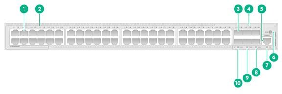
S5170-28S-EI
Figure 1 Front panel
|
(1) 10/100/1000BASE-T autosensing Ethernet port |
(2) SFP+ port |
|
(3) Serial console port (CONSOLE) |
(4) 10/100/1000BASE-T autosensing Ethernet port LED |
|
(5) System status LED (SYS) |
(6) SFP+ port LED |
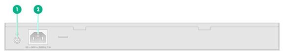
|
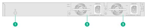
(1) Grounding screw |
(2) AC-input power receptacle |
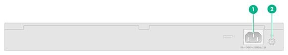
S5170-54S-EI
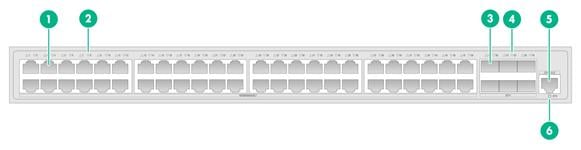
Figure 3 Front panel
|
(1) 10/100/1000BASE-T autosensing Ethernet port |
(2) 10/100/1000BASE-T autosensing Ethernet port LED |
|
(3) SFP+ port |
(4) SFP+ port LED |
|
(5) Serial console port (CONSOLE) |
(6) System status LED (SYS) |
|
(1) AC-input power receptacle |
(2) Grounding screw |
S5170-54S-EI-DP
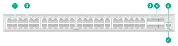
Figure 5 Front panel
|
(1) 10/100/1000BASE-T autosensing Ethernet port |
(2) 10/100/1000BASE-T autosensing Ethernet port LED |
|
(3) SFP+ port |
(4) SFP+ port LED |
|
(5) Serial console port (CONSOLE) |
(6) System status LED (SYS) |
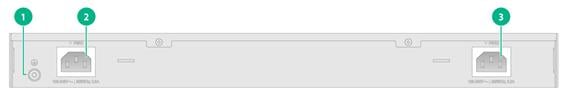
Figure 6 Rear panel
|
(1) Grounding screw |
(2) AC-input power receptacle 1 |
|
(3) AC-input power receptacle 2 |
|
The S5170-54S-EI-DP switch has two power input receptacles on the rear panel. You can use one power feed or two power feeds for 1+1 redundancy for the switch.
S5170-28S-HPWR-EI
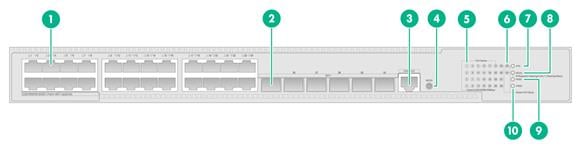
Figure 7 Front panel
|
(1) 10/100/1000BASE-T-PoE+ autosensing Ethernet port |
(2) SFP+ port |
|
(3) Serial console port (CONSOLE) |
(4) 10/100/1000BASE-T-PoE+ autosensing Ethernet port LED |
|
(5) System status LED (SYS) |
(6) Mode LED (MODE) |
|
(7) SFP+ port LED |
(8) Mode button |
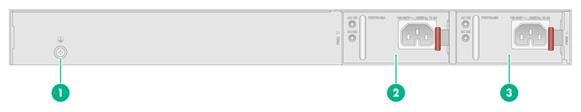
|
(1) Grounding screw |
(2) AC-input power receptacle |
S5170-54S-PWR-EI
Figure 9 Front panel
|
(1) 10/100/1000BASE-T-PoE+ autosensing Ethernet port |
(2) 10/100/1000BASE-T-PoE+ autosensing Ethernet port LED |
|
(3) SFP+ port |
(4) SFP+ port LED |
|
(5) Serial console port (CONSOLE) |
(6) Mode button |
|
(7) System status LED (SYS) |
(8) Mode LED (MODE) |

|
(1) Grounding screw |
(2) AC-input power receptacle |
S5170-36F-EI
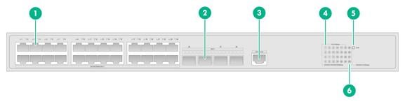
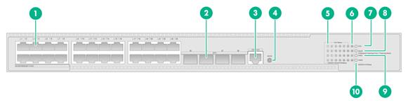
Figure 11 Front panel

|
(1) SFP port |
(2) 10/100/1000BASE-T autosensing Ethernet port |
|
(3) SFP+ port |
(4) Serial console port (CONSOLE) |
|
(5) SFP port LED |
(6) 10/100/1000BASE-T autosensing Ethernet port LED |
|
(7) System status LED (SYS) |
(8) SFP+ port LED |
|
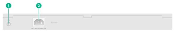
(1) AC-input power receptacle |
(2) Grounding screw |
S5170-36F-EI-DP
Figure 13 Front panel
|
(1) SFP port |
(2) 10/100/1000BASE-T autosensing Ethernet port |
|
(3) SFP+ port |
(4) Serial console port (CONSOLE) |
|
(5) SFP port LED |
(6) 10/100/1000BASE-T autosensing Ethernet port LED |
|
(7) System status LED (SYS) |
(8) AC power status LED 1 (PWR1) |
|
(9) AC power status LED 2 (PWR2) |
(10) SFP+ port LED |
Figure 14 Rear panel
|
(1) Grounding screw |
(2) AC-input power receptacle 1 |
|
(3) AC-input power receptacle 2 |
|
The S5170-36F-EI-DP switch has two power input receptacles on the rear panel. You can use one power feed or two power feeds for 1+1 redundancy for the switch.
S5570S-EI switch series
S5570S-28S-EI
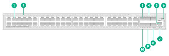
Figure 15 Front panel
|
(1) 10/100/1000BASE-T autosensing Ethernet port |
(2) SFP+ port |
|
(3) Serial console port (CONSOLE) |
(4) 10/100/1000BASE-T autosensing Ethernet port LED |
|
(5) System status LED (SYS) |
(6) Mode LED (MODE) |
|
(7) Power supply 1 status LED (PWR1) |
(8) Power supply 2 status LED (PWR2) |
|
(9) SFP+ port LED |
(10) Mode button |
|
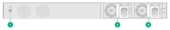
(1) Grounding screw |
(2) Power supply 1 (PWR1) |
|
(3) Power supply 2 (PWR2) |
|
The S5570S-28S-EI switch has two power supply slots on the rear panel. You can install one or two power supplies for the switch as required. In Figure 16, two PSR75-12A AC power modules are installed in the power supply slots.
The S5570S-28S-EI switch with a product code of LS-5570S-28S-EI is shipped with power supply slot PWR1 empty and power supply slot PWR2 installed with a filler panel.
The S5570S-28S-EI switch with a product code of LS-5570S-28S-EI-GL supports shipment with power supplies installed. If you hope that the switch is shipped with the purchased power supplies installed, contact the H3C sales personnel.
S5570S-54S-EI
Figure 17 Front panel
|
(1) 10/100/1000BASE-T autosensing Ethernet port |
(2) 10/100/1000BASE-T autosensing Ethernet port LED |
|
(3) SFP+ port |
(4) SFP+ port LED |
|
(5) Serial console port (CONSOLE) |
(6) Mode button |
|
(7) System status LED (SYS) |
(8) Mode LED (MODE) |
|
(9) Power supply 2 status LED (PWR2) |
(10) Power supply 1 status LED (PWR1) |
|
(1) Grounding screw |
(2) Power supply 1 (PWR1) |
|
(3) Power supply 2 (PWR2) |
|
The S5570S-54S-EI switch has two power supply slots on the rear panel. You can install one or two power supplies for the switch as required. In Figure 18, two PSR75-12A AC power modules are installed in the power supply slots.
The S5570S-54S-EI switch with a product code of LS-5570-54S-EI is shipped with power supply slot PWR1 empty and power supply slot PWR2 installed with a filler panel.
The S5570S-54S-EI switch with a product code of LS-5570-54S-EI-GL supports shipment with power supplies installed. If you hope that the switch is shipped with the purchased power supplies installed, contact the H3C sales personnel.
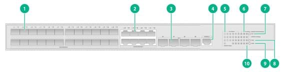
S5570S-28S-HPWR-EI
Figure 19 Front panel
|
(1) 10/100/1000BASE-T-PoE+ autosensing Ethernet port |
(2) SFP+ port |
|
(3) Serial console port (CONSOLE) |
(4) Mode button |
|
(5) 10/100/1000BASE-T-PoE+ autosensing Ethernet port LED |
(6) SFP+ port LED |
|
(7) System status LED (SYS) |
(8) Mode LED (MODE) |
|
(9) Power supply 1 status LED (PWR1) |
(10) Power supply 2 status LED (PWR2) |

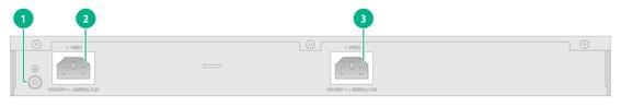
|
(1) Grounding screw |
(2) Power supply 1 (PWR1) |
|
(3) Power supply 2 (PWR2) |
|
The S5570S-28S-HPWR-EI switch has two power supply slots on the rear panel and came with power supply slot PWR1 empty and power supply slot PWR2 installed with a filler panel. You can install one or two power supplies for the switch as required. In Figure 20, two PSR360-56A AC power modules are installed in the power supply slots.
S5570S-28S-HPWR-EI-A
Figure 21 Front panel
|
(1) 10/100/1000BASE-T-PoE+ autosensing Ethernet port |
(2) USB port |
|
(3) 10/100/1000BASE-T-PoE+ autosensing Ethernet port LED |
(4) SFP+ port LED |
|
(5) System status LED (SYS) |
(6) Mode LED (MODE) |
|
(7) Power supply 1 status LED (PWR1) |
(8) Power supply 2 status LED (PWR2) |
|
(9) Mode button |
(10) Serial console port |
|
(11) SFP+ port |
|
|
(1) Grounding screw |
(2) Power supply 1 (PWR1) |
|
(3) Power supply 2 (PWR2) |
|
The S5570S-28S-HPWR-EI-A switch has two power supply slots on the rear panel. You can install one or two power supplies for the switch as required. In Figure 22, two PSR600-54A-B AC power supplies are installed in the power supply slots.
The S5570S-28S-HPWR-EI-A switch with product code LS-5570S-28S-HPWR-EI-A came with power supply 1 slot empty and power supply slot 2 installed with a filler panel.
The S5570S-28S-HPWR-EI-A switch with product code LS-5570S-28S-HPWR-EI-A-GL supports shipment with power supplies installed. To have the switch shipped with power supplies installed, contact the H3C marketing personnel and add your requirements to the order in advance.
S5570S-54S-PWR-EI
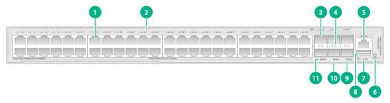
Figure 23 Front panel
|
(1) 10/100/1000BASE-T-PoE+ autosensing Ethernet port |
(2) 10/100/1000BASE-T-PoE+ autosensing Ethernet port LED |
|
(3) SFP+ port |
(4) SFP+ port LED |
|
(5) Serial console port (CONSOLE) |
(6) Mode button |
|
(7) System status LED (SYS) |
(8) Mode LED (MODE) |
|
(9) Power supply 2 status LED (PWR2) |
(10) Power supply 1 status LED (PWR1) |

|
(1) Grounding screw |
(2) Power supply 1 (PWR1) |
|
(3) Power supply 2 (PWR2) |
|
The S5570S-54S-PWR-EI switch has two power supply slots on the rear panel and comes with power supply slot PWR1 empty and power supply slot PWR2 installed with a filler panel. You can install one or two power supplies for the switch as required. In Figure 24, two PSR720-56A power modules are installed in the power supply slots.
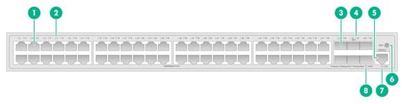
S5570S-54S-PWR-EI-A
Figure 25 Front panel
|
(1) 10/100/1000BASE-T autosensing Ethernet port |
(2) 10/100/1000BASE-T autosensing Ethernet port LED |
|
(3) SFP+ port |
(4) SFP+ port LED |
|
(5) Serial console port (CONSOLE) |
(6) Mode button |
|
(7) System status LED (SYS) |
(8) USB port |
|
(9) Mode LED (MODE) |
(10) Power supply 2 status LED (PWR2) |
|
(11) Power supply 1 status LED (PWR1) |
|

|
(1) Grounding screw |
(2) Power supply 1 (PWR1) |
|
(3) Power supply 2 (PWR2) |
|
The S5570S-54S-PWR-EI-A switch has two power supply slots on the rear panel. You can install one or two power supplies for the switch as required. In Figure 26, two PSR600-54A-B AC power supplies are installed in the power supply slots.
The S5570S-54S-PWR-EI-A switch with product code LS-5570S-54S-PWR-EI-A came with power supply 1 slot empty and power supply slot 2 installed with a filler panel.
The S5570S-54S-PWR-EI-A switch with product code LS-5570S-54S-PWR-EI-A-GL supports shipment with power supplies installed. To have the switch shipped with power supplies installed, contact the H3C marketing personnel and add your requirements to the order in advance.
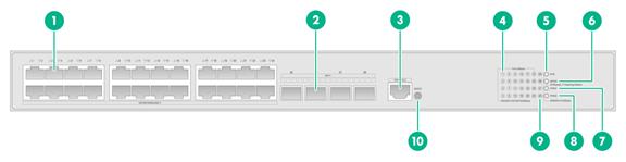
S5570S-36F-EI
Figure 27 Front panel

|
(1) SFP port |
(2) 10/100/1000BASE-T autosensing Ethernet port |
|
(3) SFP+ port |
(4) Serial console port (CONSOLE) |
|
(5) SFP port LED |
(6) 10/100/1000BASE-T autosensing Ethernet port LED |
|
(7) System status LED (SYS) |
(8) Mode LED (MODE) |
|
(9) Power supply 1 status LED (PWR1) |
(10) Power supply 2 status LED (PWR2) |
|
(11) SFP+ port LED |
(12) Mode button |

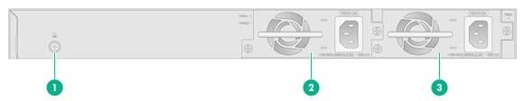
|
(1) Grounding screw |
(2) Power supply 1 (PWR1) |
|
(3) Power supply 2 (PWR2) |
|
The S5570S-36F-EI switch has two power supply slots on the rear panel. You can install one or two power supplies for the switch as required. In Figure 28, two PSR75-12A AC power modules are installed in the power supply slots.
The S5570S-36F-EI switch with a product code of LS-5570S-36F-EI is shipped with power supply slot PWR1 empty and power supply slot PWR2 installed with a filler panel.
The S5570S-36F-EI switch with a product code of LS-5570S-36F-EI-GL supports shipment with power supplies installed. If you hope that the switch comes with the purchased power supplies installed, contact the H3C sales personnel.
S5570S-54F-EI
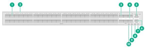
Figure 29 Front panel
|
(1) SFP port |
(2) SFP port LED |
|
(3) SFP+ port |
(4) SFP+ port LED |
|
(5) Serial console port (CONSOLE) |
(6) Management Ethernet port |
|
(7) System status LED (SYS) |
(8) Management Ethernet port LED |
|
(9) Power supply 2 status LED (PWR2) |
(10) Power supply 1 status LED (PWR1) |

|
(1) Grounding screw |
(2) Power supply 1 (PWR1) |
|
(3) Power supply 2 (PWR2) |
|
The S5570S-54F-EI switch has two power supply slots on the rear panel. You can install one or two power supplies for the switch as required. In Figure 30, two PSR75-12A AC power modules are installed in the power supply slots.
The S5570S-54F-EI switch with a product code of LS-5570S-54F-EI is shipped with power supply slot PWR1 empty and power supply slot PWR2 installed with a filler panel.
The S5570S-54F-EI switch with a product code of LS-5570S-54F-EI-GL supports shipment with power supplies installed. If you hope that the switch comes with the purchased power supplies installed, contact the H3C sales personnel.
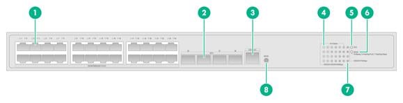
S5570S-30MS-UPWR-EI
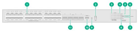
Figure 31 Front panel
|
(1) 2.5G/1000/100BASE-T-PoE++ port |
(2) SFP+ port |
|
(3) Serial console port (CONSOLE) |
(4) Mode button |
|
(5) 2.5G/1000/100BASE-T-PoE++ port LED |
(6) SFP+ port LED |
|
(7) System status LED (SYS) |
(8) Mode LED (MODE) |
|
(9) Power supply 1 status LED (PWR1) |
(10) Power supply 2 status LED (PWR2) |
|
(1) Grounding screw |
(2) Power supply 1 (PWR1) |
|
(3) Power supply 2 (PWR2) |
|
The S5570S-30MS-UPWR-EI switch has two power supply slots on the rear panel and comes with power supply slot PWR1 empty and power supply slot PWR2 installed with a filler panel. You can install one or two power supplies for the switch as required. In Figure 32, two PSR720-56A AC power modules are installed in the power supply slots.
Removable components and compatibility matrixes
Some switch models support removable components. Table 10 describes the removable components available for the switch.
Table 10 Compatibility matrix between switches and removable components
|
FRU model |
S5570S-28S-EI S5570S-54S-EI S5570S-36F-EI S5570S-54F-EI |
S5570S-28S-HPWR-EI S5570S-54S-PWR-EI S5570S-30MS-UPWR-EI |
S5570S-30MS-UPWR-EI |
S5570S-28S-HPWR-EI-A S5570S-54S-PWR-EI-A |
||
|
Removable power supplies |
||||||
|
CA-70A12 |
Supported |
Not supported |
Not supported |
Not supported |
||
|
PSR75-12A |
Supported |
Not supported |
Not supported |
Not supported |
||
|
PSR150-D1 |
Supported |
Not supported |
Not supported |
Not supported |
||
|
PSR180-56A |
Not supported |
Supported |
Not supported |
Not supported |
||
|
PSR360-56A |
Not supported |
Supported |
Supported |
Not supported |
||
|
PSR720-56A |
Not supported |
Supported |
Supported |
Not supported |
||
|
PSR1100-56A |
Not supported |
Supported |
Supported |
Not supported |
||
|
PSR560-56D |
Not supported |
Supported |
Supported |
Not supported |
||
|
PSR600-54A-B |
Not supported |
Not supported |
Not supported |
Supported |
||
|
PSR920-54A-B |
Not supported |
Not supported |
Not supported |
Supported |
||
|
PSR1600-54A-B |
Not supported |
Not supported |
Not supported |
Supported |
||
With a CA-70A12 or PSR75-12A power supply installed, the S5570S-54F-EI switch supports a maximum of 12 SFP-GE-T or SFP-GE-T-D GE copper transceiver modules.
Do not install PSR600-54A-B and PSR1600-54A-B power supplies on the same switch.
For non-PoE switches, you can install one power supply, or two power supplies for 1+1 redundancy on the switch. The switch supports a mixture of an AC power supply and a DC power supply.
For PoE switches, you can install one power supply, or two power supplies for 1+1 redundancy on the switch. PoE capabilities vary by power supply configuration. When a power supply fails, PoE capabilities of the switch might decrease. For more information about PoE power, see Table 8.
For the S5570S-EI switch series, the removable components available for the switch might change over time. For the most recent removable components available for the switch, see the release notes.
For the S5570S-EI switch series, use the display device manuinfo power command to view electronic label information about the power supply. The CA-70A12 power supply does support reading electronic label information.
Removable power supplies
Table 11 Power supplies available for the switch
|
Power supply model |
Item |
Specifications |
Reference |
|
CA-70A12 |
Rated input voltage |
100 VAC to 240 VAC @ 50 Hz or 60 Hz |
H3C CA-70A12 Power Supply User Manual |
|
Max input voltage |
90 VAC to 290 VAC @ 47 Hz to 63 Hz |
||
|
Max output power |
70 W |
||
|
PSR75-12A |
Rated input voltage |
100 VAC to 240 VAC @ 50 Hz or 60 Hz |
H3C PSR75-12A Power Module User Manual |
|
Max input voltage |
90 VAC to 290 VAC @ 47 Hz to 63 Hz |
||
|
Max output power |
75 W |
||
|
PSR150-D1 |
Rated input voltage |
–48 VDC to –60 VDC |
H3C PSR150-A & PSR150-D Power Supply Series User Manual |
|
Max input voltage |
–36 VDC to –72 VDC |
||
|
Max output power |
150 W |
||
|
PSR180-56A |
Rated input voltage |
AC: 100 VAC to 240 VAC @ 50 Hz or 60 Hz DC: 240 VDC |
H3C PSR180-56A Power Module User Manual |
|
Max input voltage |
AC: 85 VAC to 290 VAC @ 47 Hz to 63 Hz DC: 180 VDC to 320 VDC |
||
|
Max output power |
180 W |
||
|
PSR360-56A |
Rated input voltage |
100 VAC to 240 VAC @ 50 Hz or 60 Hz |
H3C PSR360-56A Power Module User Manual |
|
Max input voltage |
90 VAC to 264 VAC @ 47 Hz to 63 Hz |
||
|
Max output power |
360 W |
||
|
PSR560-56D |
Rated input voltage |
–48 VDC to –60 VDC |
H3C PSR560-56D Power Module User Manual |
|
Max input voltage |
–36 VDC to –72 VDC |
||
|
Max output power |
560 W |
||
|
PSR720-56A |
Rated input voltage |
100 VAC to 240 VAC @ 50 Hz or 60 Hz |
H3C PSR720-56A Power Module User Manual |
|
Max input voltage |
90 VAC to 264 VAC @ 47 Hz to 63 Hz |
||
|
Max output power |
720 W |
||
|
PSR1110-56A |
Rated input voltage |
115 VAC to 240 VAC @ 50 Hz or 60 Hz |
H3C PSR1110-56A Power Module User Manual |
|
Max input voltage |
102.5 VAC to 264 VAC @ 47 Hz to 63 Hz |
||
|
Max output power |
1110 W |
||
|
PSR600-54A-B |
Rated input voltage |
AC: 100 VAC to 240 VAC @ 50 Hz or 60 Hz DC: 240 VDC |
H3C PSR600-54A-B Power Module User Manual |
|
Max input voltage |
AC: 90 VAC to 290 VAC @ 47 to 63 Hz DC: 180 VDC to 320 VDC |
||
|
Max output power |
600 W |
||
|
PSR920-54A-B |
Rated input voltage |
· AC: ¡ 100 VAC to 130 VAC @ 50/60 Hz ¡ 200 VAC to 240 VAC @ 50/60 Hz · DC: 240 VDC |
H3C PSR920-54A-B Power Module User Manual |
|
Max input voltage |
AC: 90 VAC to 290 VAC @ 47 to 63 Hz DC: 180 VDC to 320 VDC |
||
|
Max output power |
920 W |
||
|
PSR1600-54A-B |
Rated input voltage |
AC: 100 VAC to 240 VAC @ 50/60 Hz DC: 240 VDC |
H3C PSR1600-54A-B Power Module User Manual |
|
Max input voltage |
AC: 90 VAC to 290 VAC @ 47 to 63 Hz DC: 180 VDC to 320 VDC |
||
|
Max output power |
1600 W |
|
|
NOTE: The PSR1110-56A power module, including the handle, adds 64 mm (2.52 in) to the chassis depth. |
Ports and LEDs
Ports
Console port
Table 12 Console port specifications
|
Item |
Specification |
|
Connector type |
RJ-45 |
|
Compliant standard |
EIA/TIA-232 |
|
Transmission baud rate |
9600 bps (default) to 115200 bps |
|
Services |
· Provides connection to an ASCII terminal · Provides connection to the serial port of a local PC running terminal emulation program |
|
Compatible devices |
All device models |
Management Ethernet port
Table 13 Management Ethernet port specifications
|
Item |
Specification |
|
Connector type |
RJ-45 |
|
Port transmission rate |
· 10 Mbps, half/full duplex · 100 Mbps, half/full duplex · 1000 Mbps, full duplex · MDI/MDI-X autosensing |
|
Transmission medium |
Category-5 or above twisted pair cable |
|
Max transmission distance |
100 m (328.08 ft) |
|
Compliant standard |
IEEE 802.3i, IEEE 802.3u, and IEEE 802.3ab |
|
Functions and services |
Switch software and Boot ROM upgrade, network management |
|
Compatible devices |
S5570S-54F-EI switch |
2.5G/1000/100BASE-T Ethernet port
Table 14 2.5G/1000/100BASE-T Ethernet port specifications
|
Item |
Specification |
|
Connector type |
RJ-45 |
|
Rate, duplex mode, and auto-MDI/MDI-X |
· 100 Mbps, half/full duplex · 1 Gbps, full duplex · 2.5 Gbps, full duplex · MDI/MDI-X autosensing |
|
Max transmission distance |
· 2.5G mode: 100 m (328.08 ft) · 1G mode: 140 m (459.32 ft) · 100M mode: 200 m (656.17 ft) NOTE: The maximum transmission distance between a PSE and PD depends on the peer device capability and twisted pair cable quality. The data above is only for your reference. |
|
Transmission medium |
Category 5e or above twisted pair cable |
|
Compliant standard |
IEEE 802.3ab and IEEE 802.3an |
|
Compatible devices |
S5570S-30MS-UPWR-EI switch |
10/100/1000BASE-T Ethernet port
Table 15 10/100/1000BASE-T Ethernet port specifications
|
Item |
Specification |
|
Connector type |
RJ-45 |
|
Rate, duplex mode, and auto-MDI/MDI-X |
· 10 Mbps, half/full duplex · 100 Mbps, half/full duplex · 1000 Mbps, full duplex · MDI/MDI-X autosensing |
|
Max transmission distance |
100 m (328.08 ft) |
|
Transmission medium |
Category 5 or above twisted pair cable |
|
Compliant standard |
IEEE 802.3i, IEEE 802.3u, and IEEE 802.3ab |
|
Compatible devices |
All device models (excluding the S5570S-54F-EI switch) |
SFP port
Table 16 SFP port specifications
|
Item |
Specification |
|
Interface type |
SFP port |
|
Compatible transceiver modules and cables |
· FE SFP transceiver modules in Table 17 · GE SFP transceiver modules and cables in Table 19 |
|
Compatible devices |
S5170-36F-EI, S5170-36F-EI-DP, S5570S-36F-EI, and S5570S-54F-EI switches |
|
Restrictions and guidelines |
With a CA-70A12 or PSR75-12A power supply installed, the S5570S-54F-EI switch supports a maximum of 12 GE copper transceiver modules. |
Table 17 FE SFP transceiver modules available for the SFP ports
|
FE SFP transceiver module |
Central wavelength (nm) |
Connector |
Fiber diameter (µm) |
Max transmission distance |
|
SFP-GE/FE-LX10-SM1310 |
1310 |
LC |
Single-mode, 9/125 |
10 km (6.21 miles) |
|
SFP-FE-SX-MM1310-A |
1310 |
LC |
Multi-mode, 50/125 |
2 km (1.24 miles) |
|
Multi-mode, 62.5/125 |
||||
|
SFP-FE-LX-SM1310-A |
1310 |
LC |
Single-mode, 9/125 |
15 km (9.32 miles) |
|
SFP-FE-LX-SM1310-D |
1310 |
LC |
Single-mode, 9/125 |
15 km (9.32 miles) |
|
SFP-FE-LH40-SM1310 |
1310 |
LC |
Single-mode, 9/125 |
40 km (24.86 miles) |
|
SFP-FE-LH80-SM1550 |
1550 |
LC |
Single-mode, 9/125 |
80 km (49.71 miles) |
|
SFP-FE-LX-SM1310-BIDI |
TX: 1310 RX: 1550 |
LC |
Single-mode, 9/125 |
15 km (9.32 miles) |
|
SFP-FE-LX-SM1550-BIDI |
TX: 1550 RX: 1310 |
LC |
Single-mode, 9/125 |
15 km (9.32 miles) |
|
|
IMPORTANT: The SFP-FE-LX-SM1310-BIDI and SFP-FE-LX-SM1550-BIDI transceiver modules must be used in pairs. For example, if one end uses the SFP-FE-LX-SM1310-BIDI transceiver module, the other end must use the SFP-FE-LX-SM1550-BIDI transceiver module. |
SFP+ port
Table 18 SFP+ port specifications
|
Item |
Specification |
|
Interface type |
SFP+ port |
|
Compatible transceiver modules and cables |
· GE SFP transceiver modules and cables in Table 19 · 10-GE SFP+ transceiver modules and cables in Table 20, Table 21, and Table 22 |
|
Compatible devices |
All device models |
|
Restrictions and guidelines |
You can install a maximum of two 10-GE transceiver modules with a transmission distance of 80 km (49.71 miles). |
Table 19 GE SFP transceiver modules and cables available for the SFP+ ports
|
GE SFP transceiver module and cable |
Central wavelength (nm) |
Connector |
Cable/Fiber type and diameter (µm) |
Modal bandwidth (MHz × km) |
Max transmission distance |
|
GE SFP transceiver modules |
|||||
|
SFP-GE-T |
N/A |
RJ-45 |
Twisted pair cable |
N/A |
100 m (328.08 ft) |
|
SFP-GE-T-D |
N/A |
RJ-45 |
Twisted pair cable |
N/A |
100 m (328.08 ft) |
|
SFP-GE-SX-MM850-A |
850 |
LC |
Multi-mode, 50/125 |
500 |
550 m (1804.46 ft) |
|
400 |
500 m (1640.42 ft) |
||||
|
Multi-mode, 62.5/125 |
200 |
275 m (902.23 ft) |
|||
|
160 |
200 m (656.17 ft) |
||||
|
SFP-GE-SX-MM850-D |
850 |
LC |
Multi-mode, 50/125 |
500 |
550 m (1804.46 ft) |
|
400 |
500 m (1640.42 ft) |
||||
|
Multi-mode, 62.5/125 |
200 |
275 m (902.23 ft) |
|||
|
160 |
200 m (656.17 ft) |
||||
|
SFP-GE-LX-SM1310-A |
1310 |
LC |
Single-mode, 9/125 |
N/A |
10 km (6.21 miles) |
|
Multi-mode, 50/125 |
500 or 400 |
550 m (1804.46 ft) |
|||
|
Multi-mode, 62.5/125 |
500 |
550 m (1804.46 ft) |
|||
|
SFP-GE/FE-LX10-SM1310 |
1310 |
LC |
Single-mode, 9/125 |
N/A |
10 km (6.21 miles) |
|
SFP-GE-LX-SM1310-D |
1310 |
LC |
Single-mode, 9/125 |
N/A |
10 km (6.21 miles) |
|
SFP-GE-LH40-SM1310 |
1310 |
LC |
Single-mode, 9/125 |
N/A |
40 km (24.86 miles) |
|
SFP-GE-LH40-SM1310-D |
1310 |
LC |
Single-mode, 9/125 |
N/A |
40 km (24.86 miles) |
|
SFP-GE-LH40-SM1550 |
1550 |
LC |
Single-mode, 9/125 |
N/A |
40 km (24.86 miles) |
|
SFP-GE-LH80-SM1550 |
1550 |
LC |
Single-mode, 9/125 |
N/A |
80 km (49.71 miles) |
|
SFP-GE-LH80-SM1550-D |
1550 |
LC |
Single-mode, 9/125 |
N/A |
80 km (49.71 miles) |
|
SFP-GE-LH100-SM1550 |
1550 |
LC |
Single-mode, 9/125 |
N/A |
100 km (62.14 miles) |
|
SFP-GE-LX-SM1310-BIDI |
TX: 1310 RX: 1490 |
LC |
Single-mode, 9/125 |
N/A |
10 km (6.21 miles) |
|
SFP-GE-LX-SM1490-BIDI |
TX: 1490 RX: 1310 |
LC |
Single-mode, 9/125 |
N/A |
10 km (6.21 miles) |
|
SFP-GE-LH40-SM1310-BIDI |
TX: 1310 RX: 1550 |
LC |
Single-mode, 9/125 |
N/A |
40 km (24.86 miles) |
|
SFP-GE-LH40-SM1550-BIDI |
TX: 1550 RX: 1310 |
LC |
Single-mode, 9/125 |
N/A |
40 km (24.86 miles) |
|
SFP-GE-LH70-SM1490-BIDI |
TX: 1490 RX: 1550 |
LC |
Single-mode, 9/125 |
N/A |
70 km (43.50 miles) |
|
SFP-GE-LH70-SM1550-BIDI |
TX: 1550 RX: 1490 |
LC |
Single-mode, 9/125 |
N/A |
70 km (43.50 miles) |
|
GE SFP cable |
|||||
|
SFP-STACK-Kit |
N/A |
N/A |
N/A |
SFP cable |
1.5 m (4.92 ft) |
|
|
IMPORTANT: The SFP-GE-LX-SM1310-BIDI and SFP-GE-LX-SM1490-BIDI transceiver modules, SFP-GE-LH40-SM1310-BIDI and SFP-GE-LH40-SM1550-BIDI transceiver modules, and SFP-GE-LH70-SM1490-BIDI and SFP-GE-LH70-SM1550-BIDI transceiver modules must be used in pairs. For example, if one end uses the SFP-GE-LX-SM1310-BIDI transceiver module, the other end must use the SFP-GE-LX-SM1490-BIDI transceiver module. |
Table 20 10-GE SFP+ transceiver modules available for the SFP+ ports
|
10-GE SFP+ transceiver module |
Central wavelength (nm) |
Connector |
Fiber diameter (µm) |
Modal bandwidth (MHz × km) |
Max transmission distance |
|
SFP-XG-SX-MM850-A |
850 |
LC |
Multi-mode, 50/125 |
2000 |
300 m (984.25 ft) |
|
500 |
82 m (269.03 ft) |
||||
|
400 |
66 m (216.54 ft) |
||||
|
Multi-mode, 62.5/125 |
200 |
33 m (108.27 ft) |
|||
|
160 |
26 m (85.30 ft) |
||||
|
SFP-XG-SX-MM850-D |
850 |
LC |
Multi-mode, 50/125 |
2000 |
300 m (984.25 ft) |
|
500 |
82 m (269.03 ft) |
||||
|
400 |
66 m (216.54 ft) |
||||
|
Multi-mode, 62.5/125 |
200 |
33 m (108.27 ft) |
|||
|
160 |
26 m (85.30 ft) |
||||
|
SFP-XG-LX-SM1310 |
1310 |
LC |
Single-mode, 9/125 |
N/A |
10 km (6.21 miles) |
|
SFP-XG-LX-SM1310-D |
1310 |
LC |
Single-mode, 9/125 |
N/A |
10 km (6.21 miles) |
|
SFP-XG-LH40-SM1550 |
1550 |
LC |
Single-mode, 9/125 |
N/A |
40 km (24.86 miles) |
|
SFP-XG-LH40-SM1550-D |
1550 |
LC |
Single-mode, 9/125 |
N/A |
40 km (24.86 miles) |
|
SFP-XG-LH80-SM1550 |
1550 |
LC |
Single-mode, 9/125 |
N/A |
80 km (49.71 miles) |
|
SFP-XG-LH80-SM1550-D |
1550 |
LC |
Single-mode, 9/125 |
N/A |
80 km (49.71 miles) |
|
SFP-XG-LX-SM1270-BIDI |
TX: 1270 RX: 1330 |
LC |
Single-mode, 9/125 |
N/A |
10 km (6.21 miles) |
|
SFP-XG-LX-SM1330-BIDI |
TX: 1330 RX: 1270 |
LC |
Single-mode, 9/125 |
N/A |
10 km (6.21 miles) |
|
SFP-XG-LH40-SM1270-BIDI |
TX: 1270 RX: 1330 |
LC |
Single-mode, 9/125 |
N/A |
40 km (24.86 miles) |
|
SFP-XG-LH40-SM1330-BIDI |
TX: 1330 RX: 1270 |
LC |
Single-mode, 9/125 |
N/A |
40 km (24.86 miles) |
|
SFP-XG-LH80-SM1490-BIDI |
TX: 1490 RX: 1550 |
LC |
Single-mode, 9/125 |
N/A |
80 km (49.71 miles) |
|
SFP-XG-LH80-SM1550-BIDI |
TX: 1550 RX: 1490 |
LC |
Single-mode, 9/125 |
N/A |
80 km (49.71 miles) |
|
|
IMPORTANT: The SFP-XG-LX-SM1270-BIDI and SFP-XG-LX-SM1330-BIDI transceiver modules, SFP-XG-LH40-SM1270-BIDI and SFP-XG-LH40-SM1330-BIDI transceiver modules, and SFP-XG-LH80-SM1490-BIDI and SFP-XG-LH80-SM1550-BIDI transceiver modules must be used in pairs. For example, if one end uses an SFP-XG-LX-SM1270-BIDI transceiver module, the other end must use an SFP-XG-LX-SM1330-BIDI transceiver module. |
Table 21 SFP+ fiber cables available for the SFP+ ports
|
SFP+ fiber cable |
Cable length |
|
SFP-XG-D-AOC-7M |
7 m (22.97 ft) |
|
SFP-XG-D-AOC-10M |
10 m (32.81 ft) |
|
SFP-XG-D-AOC-20M |
20 m (65.62 ft) |
Table 22 SFP+ copper cables available for the SFP+ ports
|
SFP+ copper cable |
Cable length |
|
LSWM1STK |
0.65 m (2.13 ft) |
|
LSWM2STK |
1.2 m (3.94 ft) |
|
LSWM3STK |
3 m (9.84 ft) |
Figure 33 SFP+ cable
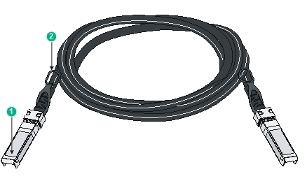
|
(1) Connector |
(2) Pull latch |
|
|
NOTE: · As a best practice, use H3C transceiver modules and network cables for the switch. · The H3C transceiver modules and network cables are subject to change over time. For the most recent list of H3C transceiver modules and cables, contact H3C Support or marketing staff. · For the specifications of H3C transceiver modules and network cables, see H3C Transceiver Modules User Guide. |
LEDs
System status LED
The system status LED shows the operating state of the switch.
Table 23 System status LED description
|
LED mark |
Status |
Description |
|
SYS |
Steady green |
The switch has started correctly. |
|
Flashing green |
The switch is performing power-on self test (POST). |
|
|
Steady red |
The switch has failed the POST or is faulty. |
|
|
Off |
The switch is powered off or the system has not started correctly. |
AC power status LED
The S5170-36F-EI-DP switch provides two AC power status LEDs on the rear panel to indicate the AC power status.
Table 24 AC power status LED description
|
LED mark |
Status |
Description |
|
PWR1/PWR2 |
Steady green |
Normal AC power input |
|
Off |
Abnormal or no AC power input |
Power status LED
The power status LEDs show the operating status of power supply 1 (PWR1) and power supply 2 (PWR2), respectively.
Table 25 Power status LED description
|
LED mark |
Status |
Description |
|
PWR1/PWR2 |
Steady green |
The power supply is present and operating correctly. |
|
Steady yellow |
The power supply is present, but it is not operating or has failed. |
|
|
Off |
No power supply is present. |
MODE LED
For the switch model that has a mode button, the mode LED (MODE) works in conjunction with the port status LEDs to show more information about the switch.
The mode LED indicates the type of information that the port status LEDs are showing.
You can use the mode button to change the indication of the mode LED. After you press the mode button to change the mode LED status into flashing green or yellow, the mode LED keeps that state for only 60 seconds and then turns steady green automatically.
Table 26 Mode LED description
|
LED mark |
Status |
Description |
|
MODE |
Steady green |
The port status LEDs indicate link state of the ports. |
|
Flashing green (available only for PoE switches) |
The port status LEDs indicate the PoE status of the ports. |
|
|
Flashing yellow |
The port status LEDs indicate the IRF member ID of the switch. For example, if the LEDs for ports 1 to 4 are steady green and the other LEDs are off, the IRF member ID of the switch is 4. |
Management Ethernet port LED
Table 27 Management Ethernet port LED description
|
LED mark |
Management Ethernet port LED status |
Description |
|
MGMT |
Steady green |
A link is present on the port. |
|
Flashing green |
The port is sending or receiving data. |
|
|
Off |
No link is present on the port. |
10/100/1000BASE-T autosensing Ethernet port LED
Table 28 shows the description of 10/100/1000BASE-T autosensing Ethernet port LEDs on switches that do not support the mode button.
Table 28 10/100/1000BASE-T autosensing Ethernet port LED description
|
LED status |
Description |
|
Steady green |
A link is present on the port. |
|
Flashing green |
The port is sending or receiving data. |
|
Off |
No link is present on the port. |
For switches that support the mode button, the 10/100/1000BASE-T autosensing Ethernet port LEDs work in conjunction with the mode LED to indicate the operating state of the ports from different aspects, as shown in Table 29.
Table 29 10/100/1000BASE-T autosensing Ethernet port LED description
|
Mode LED (MODE) status |
Ethernet port LED status |
Description |
|
Steady green (Link/Active mode) |
Steady green |
A link is present on the port. |
|
Flashing green |
The port is sending or receiving data. |
|
|
Off |
No link is present on the port. |
|
|
Flashing green (PoE mode, available only for PoE switches) |
Steady green |
PoE power supply is normal. |
|
Flashing green (1 Hz) |
· The maximum PoE power provided by the port does not meet the power requirement of the PD. · PoE power supply overcurrent, overvoltage, or short-circuit has occurred. · The remaining power of the switch does not meet the power supply requirement of the port. |
|
|
Off |
The port is not connected to a PD or PoE is not enabled on the port. |
|
|
Flashing yellow (IRF mode) |
Steady green |
The autosensing Ethernet port LEDs on the switch work in conjunction to indicate the IRF member ID of the switch. For example, if the LEDs for ports 1 to 4 are steady green and the other port LEDs are off, the IRF member ID of the switch is 4. |
2.5G/1000/100BASE-T autosensing Ethernet port LED
Table 30 2.5G/1000/100BASE-T autosensing Ethernet port LED description
|
Mode LED (MODE) status |
Ethernet port LED status |
Description |
|
Steady green (Link/Active mode) |
Steady green |
A link is present on the port. |
|
Flashing green |
The port is sending or receiving data. |
|
|
Off |
No link is present on the port. |
|
|
Flashing green (PoE mode) |
Steady green |
PoE power supply is normal. |
|
Flashing green (1 Hz) |
· The maximum PoE power provided by the port does not meet the power requirement of the PD. · PoE power supply overcurrent, overvoltage, or short-circuit has occurred. · The remaining power of the switch does not meet the power supply requirement of the port. |
|
|
Off |
The port is not connected to a PD or PoE is not enabled on the port. |
|
|
Flashing yellow (IRF mode) |
Steady green |
The autosensing Ethernet port LEDs on the switch work in conjunction to indicate the IRF member ID of the switch. For example, if the LEDs for ports 1 to 4 are steady green and the other port LEDs are off, the IRF member ID of the switch is 4. |
SFP port LED (S5570S-36F-EI switch)
Table 31 SFP port LED description
|
Mode LED (MODE) status |
SFP port LED status |
Description |
|
Steady green (Link/Active mode) |
Steady green |
A transceiver module or cable has been installed and a link is present on the port. |
|
Flashing green |
The port is sending or receiving data. |
|
|
Off |
No transceiver module or cable has been installed or no link is present on the port. |
|
|
Flashing yellow (IRF mode) |
Steady green |
The SFP port LEDs on the switch work in conjunction to indicate the IRF member ID of the switch. For example, if the LEDs for ports 1 to 4 are steady green and the other port LEDs are off, the IRF member ID of the switch is 4. |
SFP/SFP+ port LED
Table 32 SFP/SFP+ port LED description
|
SFP/SFP+ port LED status |
Description |
|
Steady green |
A transceiver module or cable has been installed and a link is present on the port. |
|
Flashing green |
The port is sending or receiving data. |
|
Off |
· No transceiver module or cable has been installed or no link is present on the port. · The mode LED is operating in IRF mode (available only for switches that support the mode button). · The mode LED is operating in PoE mode (available only for PoE switches). |
Input/output status LED on a power supply
The PSR180-56A, PSR360-56A, PSR560-56D, PSR720-56A, PSR1110-56A, PSR600-54A-B, PSR920-54A-B, and PSR1600-54A-B power supplies each have a power input status LED and a power output status LED. For more information about the LEDs, see the user manual for the power supply.
Cooling system
To dissipate heat timely and enhance system stability, the switch uses a high-performance cooling system. Consider the site ventilation design when you plan the installation site for the switch. Table 33 describes fan trays available for the switch.
Table 33 Fan trays available for the switch
|
Device model |
Fan tray type |
Airflow direction |
|
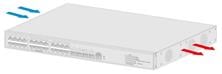
All S5170-EI switch models All S5570S-EI switch models, except the S5570S-28S-HPWR-EI-A and S5570S-54S-PWR-EI-A |
Fixed fan trays |
From the chassis left side to the right side (S5170-28S-HPWR-EI switch as an example)
|
|
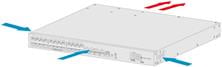
S5570S-28S-HPWR-EI-A S5570S-54S-PWR-EI-A |
From the chassis two sides and port side to the power supply side (S5570S-28S-HPWR-EI-A switch as an example)
|