- Table of Contents
-
- 11-Network Management and Monitoring Configuration Guide
- 00-Preface
- 01-System maintenance and debugging configuration
- 02-NQA configuration
- 03-iNQA configuration
- 04-NTP configuration
- 05-PTP configuration
- 06-PoE configuration
- 07-SNMP configuration
- 08-RMON configuration
- 09-Event MIB configuration
- 10-NETCONF configuration
- 11-Ansible configuration
- 12-Puppet configuration
- 13-Chef configuration
- 14-SmartMC configuration
- 15-EPA configuration
- 16-ONVIF configuration
- 17-CWMP configuration
- 18-EAA configuration
- 19-Process monitoring and maintenance configuration
- 20-Mirroring configuration
- 21-sFlow configuration
- 22-Information center configuration
- 23-Packet capture configuration
- 24-VCF fabric configuration
- 25-Cloud connection configuration
- 26-EPS agent configuration
- 27-eMDI configuration
- 28-SQA configuration
- Related Documents
-
| Title | Size | Download |
|---|---|---|
| 16-ONVIF configuration | 177.16 KB |
Restrictions and guidelines: ONVIF configuration
Display and maintenance commands for ONVIF
Example: Configuring ONVIF in a non-SmartMC network
Example: Configuring ONVIF in a SmartMC network
Configuring ONVIF
About ONVIF
ONVIF (Open Network Video Interface Forum) is an open industry forum that provides and promotes standardized interfaces for effective interoperability of IP-based physical security products. The ONVIF protocol provides access control and management of audio and video products. ONVIF can identify and monitor ONVIF endpoints (cameras) when they come online and go offline.
ONVIF provides the following functions:
· ONVIF probing—With this feature enabled, the device automatically sends ONVIF probe messages to probe ONVIF endpoints.
· ONVIF snooping—With this feature enabled, the device processes ONVIF packets from ONVIF endpoints to identify and monitor the endpoints when they come online and go offline.
ONVIF probing mechanism
Non-SmartMC networking
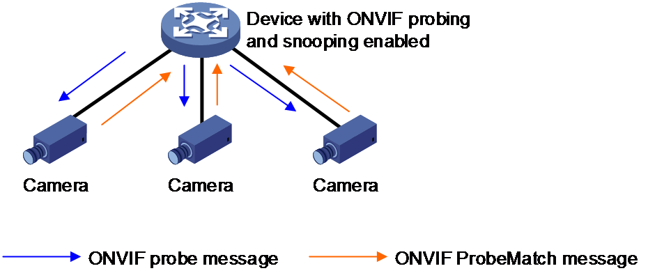
As shown in Figure 1, after you enable ONVIF probing for an interface on the device with ONVIF snooping configured:
1. The interface periodically sends ONVIF probe messages.
¡ If the interface is configured with an IPv4 address, it sends IPv4 probe messages.
¡ If the interface is configured with an IPv6 global unicast address or IPv6 link-local address, it sends IPv6 probe messages.
¡ If the interface is configured with both an IPv4 address and an IPv6 global unicast address or IPv6 link-local address, it sends both IPv4 and IPv6 probe messages.
2. After receiving an ONVIF probe message, an ONVIF endpoint returns an IPv4 or IPv6 ProbeMatch message.
3. After receiving the ProbeMatch response, the device considers the endpoint to be online and records the endpoint information.
Figure 1 Non-SmartMC networking
SmartMC networking
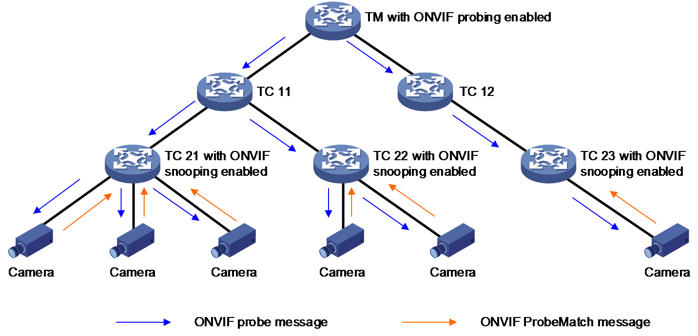
As shown in Figure 2, after you enable ONVIF probing on the TM and enable ONVIF snooping on the TM or TCs that access to ONVIF endpoints:
1. The interface on the TM periodically sends ONVIF probe messages.
¡ If the interface is configured with an IPv4 address, it sends IPv4 probe messages.
¡ If the interface is configured with an IPv6 global unicast address or IPv6 link-local address, it sends IPv6 probe messages.
¡ If the interface is configured with both an IPv4 address and an IPv6 global unicast address or IPv6 link-local address, it sends both IPv4 and IPv6 probe messages.
2. After receiving an ONVIF probe message, a TC forwards the ONVIF probe message out of all its interfaces except the receiving interface.
3. After receiving the probe message, an endpoint returns an IPv4 or IPv6 ProbeMatch message.
4. After receiving the ProbeMatch response, the TM or TC considers the endpoint to be online and records the endpoint information.
ONVIF snooping mechanism
ONVIF snooping enables a device to identify ONVIF endpoints and monitors the online state of the endpoints.
The device with ONVIF snooping enabled can identify both IPv4 and IPv6 ONVIF endpoints:
· When receiving an IPv4 ONVIF ProbeMatch message from an endpoint, it records the IPv4 address of the endpoint.
· When receiving an IPv6 ONVIF ProbeMatch message from an endpoint, it records the IPv6 address of the endpoint.
· When receiving both IPv4 and IPv6 ProbeMatch messages from an endpoint, it records the IPv4 address and IPv6 address of the endpoint.
Non-SmartMC networking
In a non-SmartMC network, the device can identify and monitor ONVIF endpoints by processing ONVIF packets after ONVIF snooping is configured on the device.
· The device considers an endpoint to be online when receiving a Hello or ProbeMatch message from the endpoint.
· The device considers an endpoint to be offline when receiving a Bye message from the endpoint or the interface connected to the endpoint went down.
· The device automatically clears information about an endpoint if the endpoint has been offline for seven consecutive days.
SmartMC networking
In a SmartMC network, the TM or TC can identify and monitor ONVIF endpoints by processing ONVIF packets after ONVIF snooping is configured on the TM or TC.
· The TM or TC considers an endpoint to be online when receiving a Hello or ProbeMatch message from the endpoint.
· The TM or TC considers an endpoint to be offline when receiving a Bye message from the endpoint or the interface connected to the endpoint went down.
· The TM or TC automatically clears information about an endpoint if the endpoint has been offline for seven consecutive days.
Restrictions and guidelines: ONVIF configuration
ONVIF is supported in both non-SmartMC and SmartMC networks. However, for the ONVIF feature to take effect in a SmartMC network, make sure the TM and all TCs support ONVIF. For more information about SmartMC, see "Configuring SmartMC."
Enabling ONVIF snooping
Restrictions and guidelines
Enable ONVIF snooping on a device connected with ONVIF endpoints. After ONVIF snooping is enabled, the device can parse ONVIF messages to sense the online state of endpoints.
For the ONVIF snooping feature to operate correctly on the device, make sure port number 3702 used for the ONVIF protocol has not been occupied by other protocols.
If an ONVIF endpoint accesses the network through a member port of an aggregate interface, ONVIF monitors the endpoint on the aggregate interface.
Procedure
1. Enter system view.
system-view
2. Enable ONVIF snooping.
onvif snooping enable
By default, ONVIF snooping is disabled.
Configuring ONVIF probing
Restrictions and guidelines
As a best practice to reduce overhead in a SmartMC network, enable ONVIF probing only on the TM.
TCs can identify ONVIF endpoints for up to 100 VLAN interfaces with the ONVIF enabled on the TM.
Procedure
1. Enter system view.
system-view
2. Enter VLAN interface view.
interface vlan-interface interface-number
3. Enable ONVIF probing.
onvif probe enable
By default, ONVIF probing is disabled.
4. Set the interval for sending probe messages.
onvif probe interval interval-value
By default, the probe interval is 30 seconds.
Display and maintenance commands for ONVIF
Execute display commands in any view.
|
Task |
Command |
|
Display ONVIF probing information. |
display onvif probe-information |
|
Display ONVIF snooping information. |
display onvif snooping-information |
ONVIF configuration examples
Example: Configuring ONVIF in a non-SmartMC network
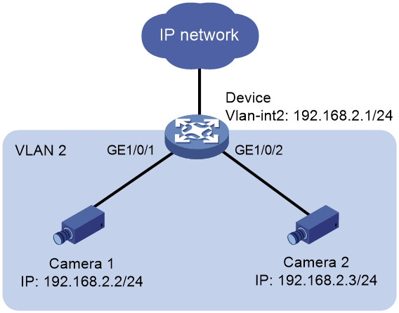
Network configuration
As shown in Figure 3, the device acts as an access device for Camera 1 and Camera 2 to access the public network. Configure ONVIF on the device, which can automatically monitor when the endpoints come online and go offline.
Procedure
# Enable ONVIF snooping.
<Device> system-view
[Device] onvif snooping enable
# Create VLAN 2.
[Device] vlan 2
[Device-vlan2] quit
# Configure an IP address for VLAN-interface 2, enable ONVIF probing, and set the interval for sending probe messages to 60 seconds.
[Device] interface vlan-interface 2
[Device-Vlan-interface1] ip address 192.168.2.1 24
[Device-Vlan-interface2] onvif probe enable
[Device-Vlan-interface2] onvif probe interval 60
[Device-Vlan-interface2] quit
# Assign Ten-GigabitEthernet 1/0/1 to VLAN 2 for user data transmission.
[Device] interface ten-gigabitethernet 1/0/1
[Device-Ten-GigabitEthernet1/0/1] port access vlan 2
[Device-Ten-GigabitEthernet1/0/1] quit
# Assign Ten-GigabitEthernet 1/0/2 to VLAN 2 for user data transmission.
[Device] interface ten-gigabitethernet 1/0/2
[Device-Ten-GigabitEthernet1/0/2] port access vlan 2
[Device-Ten-GigabitEthernet1/0/2] quit
Verifying the configuration
# On the device, verify that ONVIF can successfully snoop the endpoints.
[Device] display onvif snooping-information
Snooping status: Enabled
Endpoint information:
Endpoint MAC address: 3cef-8c7a-4ede Status: Online
Port: XGE1/0/1 VLAN: 2
IPv4 address: 192.168.2.2
IPv6 address: --
Endpoint MAC address: 3cef-8c7a-4e8f Status: Online
Port: XGE1/0/2 VLAN: 2
IPv4 address: 192.168.2.3
IPv6 address: --
# On the device, verify that ONVIF can successfully probe the endpoints.
[Device] display onvif probe-information
Probing information:
Port Status Interval(sec)
Vlan2 Enabled 60
Example: Configuring ONVIF in a SmartMC network
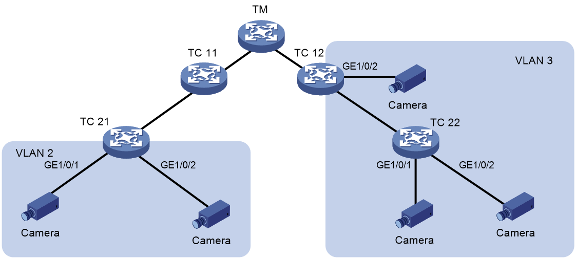
Network configuration
As shown in Figure 4, configure the devices in a SmartMC network so ONVIF can monitor cameras connected to TC 12, TC 21, and TC 22 when they come online and go offline.
Prerequisites
Establish the SmartMC network before you configure ONVIF. For more information about SmartMC network establishment, see "Configuring SmartMC."
Configuring TM
# Create VLAN 2.
<TM> system-view
[TM] vlan 2
[TM-vlan2] quit
# Enable ONVIF probing for VLAN-interface 2 and set the interval for sending probe messages to 60 seconds.
[TM] interface vlan-interface 2
[TM-Vlan-interface2] onvif probe enable
[TM-Vlan-interface2] onvif probe interval 60
[TM-Vlan-interface2] quit
# Create VLAN 3.
[TM] vlan 3
[TM-vlan3] quit
# Enable ONVIF probing for VLAN-interface 3 and set the interval for sending probe messages to 60 seconds.
[TM] interface vlan-interface 3
[TM-Vlan-interface3] onvif probe enable
[TM-Vlan-interface3] onvif probe interval 60
[TM-Vlan-interface3] quit
Configuring TC 12
# Enable ONVIF snooping.
<TC12> system-view
[TC12] onvif snooping enable
# Create VLAN 3.
[TC12] vlan 3
[TC12-vlan3] quit
# Assign Ten-GigabitEthernet 1/0/2 to VLAN 3 for user data transmission.
[TC12] interface ten-gigabitethernet 1/0/2
[TC12-Ten-GigabitEthernet1/0/2] port access vlan 3
[TC12-Ten-GigabitEthernet1/0/2] quit
Configuring TC 21
# Enable ONVIF snooping.
<TC21> system-view
[TC21] onvif snooping enable
# Create VLAN 2.
[TC21] vlan 2
[TC21-vlan2] quit
# Assign Ten-GigabitEthernet 1/0/1 and Ten-GigabitEthernet 1/0/2 to VLAN 2 for user data transmission.
[TC21] interface range ten-gigabitethernet 1/0/1 to ten-gigabitethernet 1/0/2
[TC21-if-range] port access vlan 2
[TC21-if-range] quit
Configuring TC 22
# Enable ONVIF snooping.
<TC22> system-view
[TC22] onvif snooping enable
# Create VLAN 3.
[TC22] vlan 3
[TC22-vlan2] quit
# Assign port Ten-GigabitEthernet 1/0/1 and Ten-GigabitEthernet 1/0/2 to VLAN 2 for user data transmission.
[TC22] interface range ten-gigabitethernet 1/0/1 to ten-gigabitethernet 1/0/2
[TC22-if-range] port access vlan 3
[TC22-if-range] quit
Verifying the configuration
# On TC 21, verify that ONVIF can successfully snoop the endpoints.
[TC21] display onvif snooping-information
Snooping status: Enabled
Endpoint information:
Endpoint MAC address: 3cef-8c7a-4ede Status: Online
Port: XGE1/0/1 VLAN: 2
IPv4 address: 192.168.2.2
IPv6 address: --
Endpoint MAC address: 3cef-8c7a-4e8f Status: Online
Port: XGE1/0/2 VLAN: 2
IPv4 address: 192.168.2.3
IPv6 address: --
# On the TM, display ONVIF probing information.
<TM> display onvif probe-information
Probing information:
Port Status Interval(sec)
Vlan2 Enabled 60
Vlan3 Enabled 60
