- Table of Contents
-
- 03-Layer 3—IP Services Configuration Examples
- 01-IP Unnumbered Configuration Examples
- 02-Cross-Subnet Dynamic IP Address Allocation Configuration Examples
- 03-GRE with OSPF Configuration Examples
- 04-IPv6 over IPv4 GRE Tunnel Configuration Examples
- 05-IPv6 over IPv4 Manual Tunneling with OSPFv3 Configuration Examples
- 06-ISATAP Tunnel and 6to4 Tunnel Configuration Examples
- Related Documents
-
| Title | Size | Download |
|---|---|---|
| 03-GRE with OSPF Configuration Examples | 103.28 KB |
Introduction
This document provides GRE with OSPF configuration examples.
Prerequisites
The configuration examples in this document were created and verified in a lab environment, and all the devices were started with the factory default configuration. When you are working on a live network, make sure you understand the potential impact of every command on your network.
This document assumes that you have basic knowledge of GRE and OSPF.
Example: Configuring GRE with OSPF
Network configuration
As shown in Figure 1, Device A is the gateway of the headquarters. Device B and Device C are the gateways of Branch 1 and Branch 2, respectively. The gateways have obtained public IP addresses from an ISP and can communicate with one another. Configure GRE with OSPF to meet the following requirements:
· The headquarters and the branches communicate with one another through the GRE tunnels established between the headquarters and the branches.
· The gateways learn the routes reaching the destination networks through the tunnel interfaces.
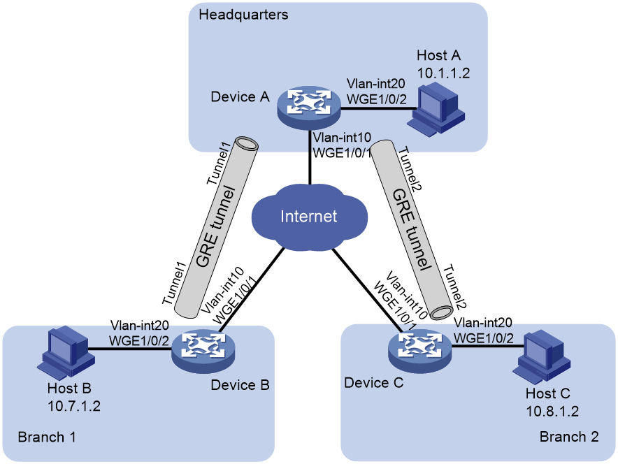
Table 1 Interface and IP address assignment
|
Device |
Interface |
IP address |
Device |
Interface |
IP address |
|
Device A |
Vlan-int10 |
191.2.1.1/24 |
Device B |
Vlan-int10 |
191.3.1.1/24 |
|
|
Vlan-int20 |
10.1.1.1/24 |
|
Vlan-int20 |
10.7.1.1/24 |
|
|
Tunnel1 |
10.5.1.1/24 |
|
Tunnel1 |
10.5.1.2/24 |
|
|
Tunnel2 |
10.6.1.1/24 |
|
|
|
|
Device C |
Vlan-int10 |
191.4.1.1/24 |
|
|
|
|
|
Vlan-int20 |
10.8.1.1/24 |
|
|
|
|
|
Tunnel2 |
10.6.1.2/24 |
|
|
|
Applicable hardware and software versions
The following matrix shows the hardware and software versions to which this configuration example is applicable:
|
Hardware |
Software version |
|
S6550X-HI switch series |
Release 1116 and later |
|
S6880 switch series |
Release 1116 and later |
|
S9820-8M switch |
Release 1116 and later |
|
S9855 switch series |
Not supported |
|
S9825 switch series |
Not supported |
Restrictions and guidelines
Encapsulated packets cannot be forwarded on Layer 3 according to the destination IP addresses and routing tables. You must create a service loopback group of the tunnel service type to loop encapsulated packets back to the forwarding module for Layer 3 forwarding.
Procedures
Before configuring GRE and OSPF, configure an IPv4 routing protocol on the gateways so that they can reach one another. (Details not shown.)
Configuring Device A
# Configure VLAN-interface 10.
<DeviceA> system-view
[DeviceA] vlan 10
[DeviceA-vlan10] port Twenty-FiveGigE 1/0/1
[DeviceA-vlan10] quit
[DeviceA] interface vlan-interface 10
[DeviceA-vlan-interface10] ip address 191.2.1.1 255.255.255.0
[DeviceA-vlan-interface10] quit
# Configure other interfaces in the same way VLAN-interface 10 is configured. (Details not shown.)
# Create service loopback group 1, and specify its service type as Tunnel.
[DeviceA] service-loopback group 1 type tunnel
# Add Twenty-FiveGigE 1/0/3 to service loopback group 1.
[DeviceA] interface Twenty-FiveGigE 1/0/3
[DeviceA-Twenty-FiveGigE1/0/3] port service-loopback group 1
[DeviceA-Twenty-FiveGigE1/0/3] quit
# Create a tunnel interface Tunnel 1, and specify the tunnel mode as GRE/IPv4.
[DeviceA] interface tunnel 1 mode gre
# Configure an IP address for the tunnel interface Tunnel 1.
[DeviceA-Tunnel1] ip address 10.5.1.1 24
# Configure the source interface of the tunnel interface Tunnel 1 as VLAN-interface 10.
[DeviceA-Tunnel1] source vlan-interface 10
# Configure the destination address of the tunnel interface Tunnel 1 as the IP address of VLAN-interface 10 on Device B.
[DeviceA-Tunnel1] destination 191.3.1.1
[DeviceA-Tunnel1] quit
# Create a tunnel interface Tunnel 2, and specify the tunnel mode as GRE/IPv4.
[DeviceA] interface tunnel 2 mode gre
# Configure an IP address for the tunnel interface Tunnel 2.
[DeviceA-Tunnel2] ip address 10.6.1.1 24
# Configure the source interface of the tunnel interface Tunnel 2 as VLAN-interface 10.
[DeviceA-Tunnel2] source vlan-interface 10
# Configure the destination address of the tunnel interface Tunnel 2 as the IP address of VLAN-interface 10 on Device C.
[DeviceA-Tunnel2] destination 191.4.1.1
[DeviceA-Tunnel2] quit
# Configure the OSPF router ID as 10.6.1.1.
[DeviceA] router id 10.6.1.1
# Enable OSPF process 1.
[DeviceA] ospf 1
# Create OSPF area 0.
[DeviceA-ospf-1] area 0
# Enable OSPF on interfaces whose primary IP addresses are on network 10.1.1.0/24, 10.5.1.0/24, or 10.6.1.0/24 in area 0.
[DeviceA-ospf-1-area-0.0.0.0] network 10.1.1.0 0.0.0.255
[DeviceA-ospf-1-area-0.0.0.0] network 10.5.1.0 0.0.0.255
[DeviceA-ospf-1-area-0.0.0.0] network 10.6.1.0 0.0.0.255
Configuring Device B
# Configure VLAN-interface 10.
<DeviceB> system-view
[DeviceB] vlan 10
[DeviceB-vlan10] port Twenty-FiveGigE 1/0/1
[DeviceB-vlan10] quit
[DeviceB] interface vlan-interface 10
[DeviceB-vlan-interface10] ip address 191.3.1.1 255.255.255.0
[DeviceB-vlan-interface10] quit
# Configure other interfaces in the same way VLAN-interface 10 is configured. (Details not shown.)
# Create service loopback group 1, and specify its service type as Tunnel.
[DeviceB] service-loopback group 1 type tunnel
# Add Twenty-FiveGigE 1/0/3 to service loopback group 1.
[DeviceB] interface Twenty-FiveGigE 1/0/3
[DeviceB-Twenty-FiveGigE1/0/3] port service-loopback group 1
[DeviceB-Twenty-FiveGigE1/0/3] quit
# Create a tunnel interface Tunnel 1, and specify the tunnel mode as GRE/IPv4.
[DeviceB] interface tunnel 1 mode gre
# Configure an IP address for the tunnel interface Tunnel 1.
[DeviceB-Tunnel1] ip address 10.5.1.2 24
# Configure the source interface of the tunnel interface Tunnel 1 as VLAN-interface 10.
[DeviceB-Tunnel1] source Vlan-interface 10
# Configure the destination address of the tunnel interface Tunnel 1 as the IP address of VLAN-interface 10 on Device A.
[DeviceB-Tunnel1] destination 191.2.1.1
[DeviceB-Tunnel1] quit
# Configure the OSPF router ID as 10.7.1.1.
[DeviceB] router id 10.7.1.1
# Enable OSPF process 1.
[DeviceB] ospf 1
# Create OSPF area 0.
[DeviceB-ospf-1] area 0
# Enable OSPF on interfaces whose primary IP addresses are on network 10.7.1.0/24 or 10.5.1.0/24 in area 0.
[DeviceB-ospf-1-area-0.0.0.0] network 10.7.1.0 0.0.0.255
[DeviceB-ospf-1-area-0.0.0.0] network 10.5.1.0 0.0.0.255
Configuring Device C
# Configure VLAN-interface 10.
<DeviceC> system-view
[DeviceC] vlan 10
[DeviceC-vlan10] port Twenty-FiveGigE 1/0/1
[DeviceC-vlan10] quit
[DeviceC] interface Vlan-interface 10
[DeviceC-Vlan-interface10] ip address 191.4.1.1 255.255.255.0
[DeviceC-Vlan-interface10] quit
# Configure other interfaces in the same way VLAN-interface 10 is configured. (Details not shown.)
# Create service loopback group 1, and specify its service type as Tunnel.
[DeviceC] service-loopback group 1 type tunnel
# Add Twenty-FiveGigE 1/0/3 to service loopback group 1.
[DeviceC] interface Twenty-FiveGigE 1/0/3
[DeviceC-Twenty-FiveGigE1/0/3] port service-loopback group 1
[DeviceC-Twenty-FiveGigE1/0/3] quit
# Create a tunnel interface Tunnel 2, and specify the tunnel mode as GRE/IPv4.
[DeviceC] interface tunnel 2 mode gre
# Configure an IP address for the tunnel interface Tunnel 2.
[DeviceC-Tunnel2] ip address 10.6.1.2 24
# Configure the source interface of the tunnel interface Tunnel 2 as VLAN-interface 10.
[DeviceC-Tunnel2] source Vlan-interface 10
# Configure the destination address of the tunnel interface Tunnel 2 as the IP address of VLAN-interface 10 on Device A.
[DeviceC-Tunnel2] destination 191.2.1.1
[DeviceC-Tunnel2] quit
# Configure the OSPF router ID as 10.8.1.1.
[DeviceC] router id 10.8.1.1
# Enable OSPF process 1.
[DeviceC] ospf 1
# Create OSPF area 0.
[DeviceC-ospf-1] area 0
# Enable OSPF on interfaces whose primary IP addresses are on network 10.8.1.0/24 or 10.6.1.0/24 in area 0.
[DeviceC-ospf-1-area-0.0.0.0] network 10.8.1.0 0.0.0.255
[DeviceC-ospf-1-area-0.0.0.0] network 10.6.1.0 0.0.0.255
Verifying the configuration
# Verify that Host A can ping Host B successfully.
C:\> ping 10.7.1.2
Pinging 10.7.1.2 with 32 bytes of data:
Reply from 10.7.1.2: bytes=32 time=19ms TTL=253
Reply from 10.7.1.2: bytes=32 time<1ms TTL=253
Reply from 10.7.1.2: bytes=32 time<1ms TTL=253
Reply from 10.7.1.2: bytes=32 time<1ms TTL=253
Ping statistics for 10.7.1.2:
Packets: Sent = 4, Received = 4, Lost = 0 (0% loss),
Approximate round trip times in milli-seconds:
Minimum = 0ms, Maximum = 19ms, Average = 4ms
# Verify that Host A can ping Host C successfully.
C:\> ping 10.8.1.2
Pinging 10.8.1.2 with 32 bytes of data:
Reply from 10.8.1.2: bytes=32 time=18ms TTL=253
Reply from 10.8.1.2: bytes=32 time<1ms TTL=253
Reply from 10.8.1.2: bytes=32 time<1ms TTL=253
Reply from 10.8.1.2: bytes=32 time<1ms TTL=253
Ping statistics for 10.8.1.2:
Packets: Sent = 4, Received = 4, Lost = 0 (0% loss),
Approximate round trip times in milli-seconds:
Minimum = 0ms, Maximum = 19ms, Average = 4ms
# Verify that Host B can ping Host C successfully.
C:\> ping 10.8.1.2
Pinging 10.8.1.2 with 32 bytes of data:
Reply from 10.8.1.2: bytes=32 time=20ms TTL=251
Reply from 10.8.1.2: bytes=32 time<1ms TTL=251
Reply from 10.8.1.2: bytes=32 time<1ms TTL=251
Reply from 10.8.1.2: bytes=32 time<1ms TTL=251
Ping statistics for 10.8.1.2:
Packets: Sent = 4, Received = 4, Lost = 0 (0% loss),
Approximate round trip times in milli-seconds:
Minimum = 0ms, Maximum = 19ms, Average = 4ms
Configuration files
· Device A
#
service-loopback group 1 type tunnel
#
vlan 10
#
vlan 20
#
interface Vlan-interface10
ip address 191.2.1.1 255.255.255.0
#
interface Vlan-interface20
ip address 10.1.1.1 255.255.255.0
#
interface Twenty-FiveGigE1/0/1
port link-mode bridge
port access vlan 10
#
interface Twenty-FiveGigE1/0/2
port link-mode bridge
port access vlan 20
#
interface Twenty-FiveGigE1/0/3
port link-mode bridge
port service-loopback group 1
#
interface Tunnel1 mode gre
source vlan-interface10
destination 191.3.1.1
ip address 10.5.1.1 255.255.255.0
#
interface Tunnel2 mode gre
source vlan-interface10
destination 191.4.1.1
ip address 10.6.1.1 255.255.255.0
#
router id 10.6.1.1
#
ospf 1
area 0.0.0.0
network 10.1.1.0 0.0.0.255
network 10.5.1.0 0.0.0.255
network 10.6.1.0 0.0.0.255
#
· Device B
#
service-loopback group 1 type tunnel
#
vlan 10
#
vlan 20
#
interface Vlan-interface10
ip address 191.3.1.1 255.255.255.0
#
interface Vlan-interface20
ip address 10.7.1.1 255.255.255.0
#
interface Twenty-FiveGigE1/0/1
port link-mode bridge
port access vlan 10
#
interface Twenty-FiveGigE1/0/2
port link-mode bridge
port access vlan 20
#
interface Twenty-FiveGigE1/0/3
port link-mode bridge
port service-loopback group 1
#
interface Tunnel1 mode gre
source Vlan-interface10
destination 191.2.1.1
ip address 10.5.1.2 255.255.255.0
#
router id 10.7.1.1
#
ospf 1
area 0.0.0.0
network 10.7.1.0 0.0.0.255
network 10.5.1.0 0.0.0.255
#
· Device C
#
service-loopback group 1 type tunnel
#
vlan 10
#
vlan 20
#
interface Vlan-interface10
ip address 191.4.1.1 255.255.255.0
#
interface Vlan-interface20
ip address 10.8.1.1 255.255.255.0
#
interface Twenty-FiveGigE1/0/1
port link-mode bridge
port access vlan 10
#
interface Twenty-FiveGigE1/0/2
port link-mode bridge
port access vlan 20
#
interface Twenty-FiveGigE1/0/3
port link-mode bridge
port service-loopback group 1
#
interface Tunnel2 mode gre
source Vlan-interface10
destination 191.2.1.1
ip address 10.6.1.2 255.255.255.0
#
router id 10.8.1.1
#
ospf 1
area 0.0.0.0
network 10.8.1.0 0.0.0.255
network 10.6.1.0 0.0.0.255
#
