- Table of Contents
-
- 14-Basic network configuration
- 01-Internal-to-External Access Through NAT Configuration Examples
- 02-Layer 2 Static Aggregation Configuration Examples
- 03-Layer 2 Multicast Configuration Examples
- 04-Static VLAN Allocation Configuration Examples
- 05-URL Redirection Configuration Examples
- 06-IPv6 URL Redirection Configuration Examples
- Related Documents
-
| Title | Size | Download |
|---|---|---|
| 01-Internal-to-External Access Through NAT Configuration Examples | 152.50 KB |
|
|
|
H3C Access Controllers |
|
Internal-to-External Access Through NAT |
|
Configuration Examples |
Copyright © 2023 New H3C Technologies Co., Ltd. All rights reserved.
No part of this manual may be reproduced or transmitted in any form or by any means without prior written consent of New H3C Technologies Co., Ltd.
Except for the trademarks of New H3C Technologies Co., Ltd., any trademarks that may be mentioned in this document are the property of their respective owners.
The information in this document is subject to change without notice.
Introduction
The following information provides examples for configuring NAT to allow internal users to access the external network.
Prerequisites
This document applies to Comware-based access controllers and access points. Procedures and information in the examples might be slightly different depending on the software or hardware version of the access controllers and access points.
The configuration examples in this document were created and verified in a lab environment, and all the devices were started with the factory default configuration. When you are working on a live network, make sure you understand the potential impact of every command on your network.
This document assumes that you have basic knowledge of NAT and WLAN.
Example: Configuring NAT to allow internal users to access the external network
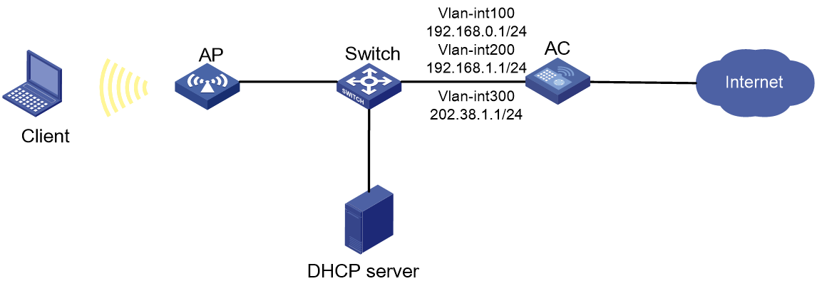
Network configuration
As shown in Figure 1, the AP and the clients obtain IP addresses through DHCP. Configure dynamic NAT on the AC's interface that connect to the external network to allow only the clients at the 192.168.1.0/24 to access the Internet.
Restrictions and guidelines
When you configure NAT to allow internal users to access the external network, follow these restrictions and guidelines:
· If you configure NAT on VLAN interfaces, use the address group as a best practice for dynamic NAT.
· Do not include the public IP address of the VLAN interface in the nat address-group.
· If the AC uses only one public IP address of the VLAN interface for dynamic NAT, use the port-range command to specify a proper port range. As a best practice, use the port range from 10000 to 65535 to ensure that the service ports on the AC are not used by NAT.
· Make sure the devices can reach each other. In this example, the routing configuration is not shown.
Procedures
Configuring the AC
Configuring the interfaces on the AC
# Create VLAN 100 and configure VLAN-interface 100. The AC will use this IP address to establish CAPWAP tunnels with APs.
<AC> system-view
[AC] vlan 100
[AC-vlan100] quit
[AC] interface vlan-interface 100
[AC-Vlan-interface100] ip address 192.168.0.1 24
[AC-Vlan-interface100] quit
# Create VLAN 200 and configure VLAN-interface 200. The clients will access the WLAN network through this VLAN.
[AC] vlan 200
[AC-vlan200] quit
[AC] interface vlan-interface 200
[AC-Vlan-interface200] ip address 192.168.1.1 24
[AC-Vlan-interface200] quit
# Create VLAN 300 and configure VLAN-interface 300. The AC will use this VLAN for dynamic address translation.
[AC] vlan 300
[AC-vlan300] quit
[AC] interface vlan-interface 300
[AC-Vlan-interface300] ip address 202.38.1.1 24
[AC-Vlan-interface300] quit
# Configure GigabitEthernet 1/0/1, the interface that connects to the switch, as a trunk port, and assign it to VLAN 100 and VLAN 200.
[AC] interface gigabitethernet 1/0/1
[AC-GigabitEthernet1/0/1] port link-type trunk
[AC-GigabitEthernet1/0/1] port trunk permit vlan 100 200
[AC-GigabitEthernet1/0/1] quit
Configuring WLAN services
# Create service template 1 and enter its view.
[AC] wlan service-template 1
# Set the SSID to service for the service template.
[AC-wlan-st-1] ssid service
# Set the authentication and key management mode to PSK, and configure simple string 12345678 as the PSK.
[AC-wlan-st-1] akm mode psk
[AC-wlan-st-1] preshared-key pass-phrase simple 12345678
# Set the CCMP cipher suite and enable the RSN IE in the beacon and probe responses.
[AC-wlan-st-1] cipher-suite ccmp
[AC-wlan-st-1] security-ie rsn
# Configure the AC to forward client data traffic. (Skip this step if the client data traffic forwarder is the AC by default.)
[AC-wlan-st-1] client forwarding-location ac
# Enable the service template.
[AC-wlan-st-1] service-template enable
[AC-wlan-st-1] quit
Configuring the AP
In large-scale networks, configure AP groups instead of single APs as a best practice.
# Create AP officeap with model WA6320, and set the serial ID to 219801A28N819CE0002T.
[AC] wlan ap officeap model WA6320
[AC-wlan-ap-officeap] serial-id 219801A28N819CE0002T
# Create AP group group1 and add AP officeap to AP group group1.
[AC] wlan ap-group group1
[AC-wlan-ap-group-group1] ap officeap
# Bind service template 1 to radio 2 in AP group group1.
[AC-wlan-ap-group-group1] ap-model WA6320
[AC-wlan-ap-group-group1-ap-model-WA6320] radio 2
[AC-wlan-ap-group-group1-ap-model-WA6320-radio-2] service-template 1 vlan 200
# Enable radio 2.
[AC-wlan-ap-group-group1-ap-model-WA6320-radio-2] radio enable
[AC-wlan-ap-group-group1-ap-model-WA6320-radio-2] quit
[AC-wlan-ap-group-group1-ap-model-WA6320] quit
[AC-wlan-ap-group-group1] quit
Configuring dynamic NAT
# Configure address group 0. Add two public IP addresses 202.38.1.2 and 202.38.1.3 to the address range.
[AC] nat address-group 0
[AC-address-group-1] address 202.38.1.2 202.38.1.3
[AC-address-group-1] quit
# Configure ACL 2000 to identify packets sourced from 192.168.1.0/24.
[AC] acl basic 2000
[AC-acl-ipv4-adv-2000] rule permit source 192.168.1.0 0.0.0.255
[AC-acl-ipv4-adv-3000] quit
# Configure outbound dynamic IP and port translation on VLAN-interface 3000 to translate the source IP address of outgoing packets permitted by ACL 2000 into addresses in the address group 0.
[AC] interface vlan-interface 300
[AC-Vlan-interface300] nat outbound 2000 address-group 0
[AC-Vlan-interface300] quit
Configuring the switch
# Create VLAN 100. The switch will use this VLAN to forward traffic on the CAPWAP tunnel between the AC and AP.
<Switch> system-view
[Switch] vlan 100
[Switch-vlan100] quit
# Create VLAN 200. This VLAN is used to forward packets from the client.
[Switch] vlan 200
[Switch-vlan200] quit
# Configure GigabitEthernet 1/0/1, the interface that connects to the AC, as a trunk port, and assign it to VLAN 100 and VLAN 200.
[Switch] interface gigabitethernet 1/0/1
[Switch-GigabitEthernet1/0/1] port link-type trunk
[Switch-GigabitEthernet1/0/1] port trunk permit vlan 100 200
[Switch-GigabitEthernet1/0/1] quit
# Configure GigabitEthernet 1/0/1, the interface that connects to the AP, as an access port, and assign it to VLAN 100.
[Switch] interface gigabitethernet 1/0/2
[Switch-GigabitEthernet1/0/2] port link-type access
[Switch-GigabitEthernet1/0/2] port access vlan 100
# Enable PoE.
[Switch-GigabitEthernet1/0/2] poe enable
[Switch-GigabitEthernet1/0/2] quit
Verifying the configuration
# Verify that when a user on the subnet 192.168.1.0/24 accesses the Internet, dynamic NAT is performed on the packets from the user. Execute the display nat session verbose command to display the NAT session information.
[AC] display nat session verbose
Slot 1:
Initiator:
Source IP/port: 192.168.1.2/1628
Destination IP/port: 202.38.1.100/21
DS-Lite tunnel peer: -
VPN instance/VLAN ID/Inline ID: -/-/-
Protocol: TCP(6)
Inbound interface: Vlan-interface200
Responder:
Source IP/port: 202.38.1.100/21
Destination IP/port: 202.38.1.2/1024
DS-Lite tunnel peer: -
VPN instance/VLAN ID/Inline ID: -/-/-
Protocol: TCP(6)
Inbound interface: Vlan-interface300
State: TCP_ESTABLISHED
Application: FTP
Start time: 2015-11-28 16:54:35 TTL: 2699s
Initiator->Responder: 1 packets 84 bytes
Responder->Initiator: 1 packets 84 bytes
Total sessions found: 1 s
Configuration files
· AC:
#
vlan 100
#
vlan 200
#
vlan 300
#
interface GigabitEthernet1/0/1
port link-type trunk
port trunk permit vlan 100 200
#
wlan service-template 1
ssid service
client forwarding-location ac
akm mode psk
preshared-key pass-phrase cipher $c$3$N//5BVbsOqdBTxi+7MJZKT6Zqh5MAmYs2ZzM
cipher-suite ccmp
security-ie rsn
service-template enable
#
interface Vlan-interface100
ip address 192.168.0.1 255.255.255.0
#
interface Vlan-interface200
ip address 192.168.1.1 255.255.255.0
#
interface Vlan-interface300
ip address 202.38.1.1 255.255.255.0
nat outbound 2000 address-group 1
#
acl basic 2000
rule 0 permit source 192.168.1.0 0.0.0.255
#
nat address-group 0
address 202.38.1.2 202.38.1.3
#
wlan ap-group group1
ap officeap
ap-model WA6320
radio 2
service-template 1 vlan 200
radio enable
#
wlan ap officeap model WA6320
serial-id 219801A28N819CE0002T
#
· Switch:
#
vlan 100
#
vlan 200
#
interface GigabitEthernet1/0/1
port link-type trunk
port trunk permit vlan 100 200
#
interface GigabitEthernet1/0/2
port link-type access
port access vlan 100
poe enable
Related documentation
· Network Connectivity Command Reference in H3C Access Controllers Command References
· Network Connectivity Configuration Guide in H3C Access Controllers Configuration Guides
· WLAN Access Command Reference in H3C Access Controllers Command References
· WLAN Access Configuration Guide in H3C Access Controllers Configuration Guides
