- Table of Contents
- Related Documents
-
| Title | Size | Download |
|---|---|---|
| 01-Text | 3.13 MB |
Logging in to the Web interface
Logging in to the Web interface for the first time
Performing Web login supported by the factory default
Performing Web login not supported by the factory default
Logging out of the Web interface
Displaying or modifying settings of a table entry
Clock synchronization protocols
NTP/SNTP time source authentication
Aggregation states of member ports in an aggregation group
QoS priority setting mode for voice traffic
Security mode and normal mode of voice VLANs
Aging timer for dynamic MAC address entries
Standards for the default path cost calculation
Spanning tree protection features
IP address configuration methods
Dynamic domain name resolution
EUI-64 address-based interface identifiers
IPv6 global unicast address configuration methods
IPv6 link-local address configuration methods
Redistributing external routes to BGP
Interface-specific static IPv4SG bindings
Periodic online user reauthentication
Mandatory authentication domain
MAC authentication configuration on a port
Intelligent port identification
System time configuration example
Administrators configuration example
Network services configuration examples
Ethernet link aggregation configuration example
Port isolation configuration example
Voice VLAN configuration example
MAC address entry configuration example
DHCP snooping configuration example
Static ARP entry configuration example
Static DNS configuration example
Dynamic DNS configuration example
Static IPv6 address configuration example
Port mirroring configuration example
IPv4 static route configuration example
IPv4 local PBR configuration example
IGMP snooping configuration example
MLD snooping configuration example
Password authentication enabled Stelnet server configuration example
Security configuration examples
ACL-based packet filter configuration example
Static IPv4 source guard configuration example
802.1X RADIUS authentication configuration example
802.1X local authentication configuration example
RADIUS-based MAC authentication configuration example
RADIUS-based port security configuration example
Direct portal authentication configuration example
Cross-subnet portal authentication configuration example
Direct portal authentication using local portal Web server configuration example
AAA for SSH users by a TACACS server configuration example
Web-based configuration cautions and guidelines
Deleting an administrator user account
Modifying the password of a user account
Saving the running configuration
Restoring the factory defaults
Deleting a file or file folder
Upgrading startup software images
Changing the member ID of an IRF member device
Changing the IRF bridge MAC persistent time
Restoring the default settings of an interface
Deleting all dynamic ARP entries
Deleting all IPv4 static routes
Deleting all IPv6 static routes
Disabling the HTTP or HTTPS service
Upgrading the startup software or configuration file for members or SmartMC groups
Upgrading the startup software or configuration file for members or WiNet groups
Overview
This user guide provides the following information:
|
Information |
Section |
|
How to log in to the Web interface for the first time. |
|
|
How to use the Web interface. |
|
|
What features you can configure from the Web interface. How to access the page for a feature or task. |
|
|
How to use features in typical scenarios. |
This user guide does not include step-by-step configuration procedures, because the webpages are task oriented by design. A configuration page typically provides links to any pages that are required to complete the task. Users do not have to navigate to multiple pages. For tasks that require navigation to multiple pages, this user guide provides configuration examples.
This user guide also does not provide detailed information about parameters. You can obtain sufficient online help, feature information, and parameter information from the webpages.
Logging in to the Web interface
Log in to the Web interface through HTTP or HTTPS.
Restrictions and guidelines
To ensure a successful login, verify that your operating system and Web browser meet the requirements, and follow the guidelines in this section.
Web browser requirements
As a best practice, use the following Web browsers:
· Internet Explorer 8 or higher.
· Google Chrome 10 or higher.
· Mozilla Firefox 4 or higher.
· Opera 11.11 or higher.
· Safari 5.1 or higher.
To access the Web interface, you must use the following browser settings:
· Accept the first-party cookies (cookies from the site you are accessing).
· To ensure correct display of webpage contents after software upgrade or downgrade, clear data cached by the browser before you log in.
· Enable active scripting or JavaScript, depending on the Web browser.
· If you are using a Microsoft Internet Explorer browser, you must enable the following security settings:
¡ Run ActiveX controls and plug-ins.
¡ Script ActiveX controls marked safe for scripting.
Default login settings
Use settings in Table 1 for the first login.
Table 1 Default login settings
|
Item |
Setting |
|
Device IP (VLAN-interface 1) |
192.168.0.233 NOTE: In Release 6315 or later, VLAN-interface 1 obtains IP addresses through DHCP by default. If the interface obtained an IP address successfully, you must use the obtained IP address for login. |
|
IP address mask |
255.255.255.0 |
|
Username |
admin |
|
Password |
admin |
|
User role |
network-admin |
Logging in to the Web interface for the first time
|
|
IMPORTANT: · Web login is supported by the factory default only for a device with management IP address, username, and password on the device label. For other devices, Web login is not supported by the factory default. To perform Web login for these devices, you must first log in to the devices through the console port and configure the settings as required. · As a best practice, change the login information and assign access permissions immediately after the first successful login for security purposes. |
Performing Web login supported by the factory default
By default, HTTP and HTTPS are enabled.
To log in to the Web interface:
1. Use an Ethernet cable to connect the configuration terminal to an Ethernet port on the device.
2. Identify the IP address and mask of the device. The device uses the default IP address. This address is labeled on the device, as shown in Figure 1. The mask is 255.255.255.0
Figure 1 Default IP address labeled on the device
![]()
3. Assign the login host an IP address in the same subnet as the device.
4. Open the browser, and then enter login information:
a. In the address bar, enter the IP address of the device.
- HTTP access—Enter the address in the http://ip-address:port or ip-address:port format.
- HTTPS access—Enter the address in the https://ip-address:port format.
The ip-address argument represents the IP address of the device. The port argument represents the HTTP or HTTPS service port. The default port number is 80 for HTTP and 443 for HTTPS. You do not need to enter the port number if you have not changed the service port setting.
b. On the login page, enter the default username (admin), password (admin), and the verification code.
c. Click Login.
5. Change the login information:
¡ To
change the password of the login user (admin at the
first login), click the Admin icon ![]() .
.
¡ To add new user accounts and assign access permissions to different users, select Device > Maintenance > Administrators.
Performing Web login not supported by the factory default
|
|
IMPORTANT: As a best practice, change the login information and assign access permissions immediately after the first successful login for security purposes. |
To log in to the Web interface:
1. Log in to the device through the console port, and then configure the Web login parameters as follows:
¡ Enable HTTP and HTTPS services.
¡ Create local user admin, assign the network-admin user role to the user, select HTTP and HTTPS for available services, and set the local user password.
¡ Configure IP address for VLAN interface 1.
2. Use an Ethernet cable to connect the configuration terminal to an Ethernet port on the device.
3. Identify the IP address and mask of the device as follows:
¡ If a DHCP server is deployed, the DHCP server automatically assigns an IP address to the device. To identify the IP address of the device, use the display ip interface brief command as follows:
<Sysname> display ip interface brief
*down: administratively down
(s): spoofing (l): loopback
Interface Physical Protocol IP address VPN instance Description
MGE0/0/0 up up 192.168.1.137 -- --
Vlan1 up up 169.254.0.255 -- --
¡ If no DHCP server is deployed, the device uses the IP address of VLAN interface 1.
4. Assign the login host an IP address in the same subnet as the device.
5. Open the browser, and then enter login information:
a. In the address bar, enter the IP address of the device.
- HTTP access—Enter the address in the http://ip-address:port or ip-address:port format.
- HTTPS access—Enter the address in the https://ip-address:port format.
The ip-address argument represents the IP address of the device. The port argument represents the HTTP or HTTPS service port. The default port number is 80 for HTTP and 443 for HTTPS. You do not need to enter the port number if you have not changed the service port setting.
b. On the login page, enter the username and password.
c. Click Login.
6. Change the login information:
¡ To
change the password of the login user (admin at the
first login), click the Admin icon ![]() .
.
¡ To add new user accounts and assign access permissions to different users, select Device > Maintenance > Administrators.
Logging out of the Web interface
|
|
IMPORTANT: · For security purposes, log out of the Web interface immediately after you finish your tasks. · You cannot log out by directly closing the browser. · The device does not automatically save the configuration when you log out of the Web interface. To prevent the loss of configuration when the device reboots, you must save the configuration. |
To log out of the Web interface:
1. Use one of the following methods to save the current configuration.
¡ Click
the Save icon ![]() in the left corner.
in the left corner.
¡ Select Device > Maintenance > Configuration to access the configuration management page.
2. Click Logout in the upper-left corner of the Web interface.
Using the Web interface
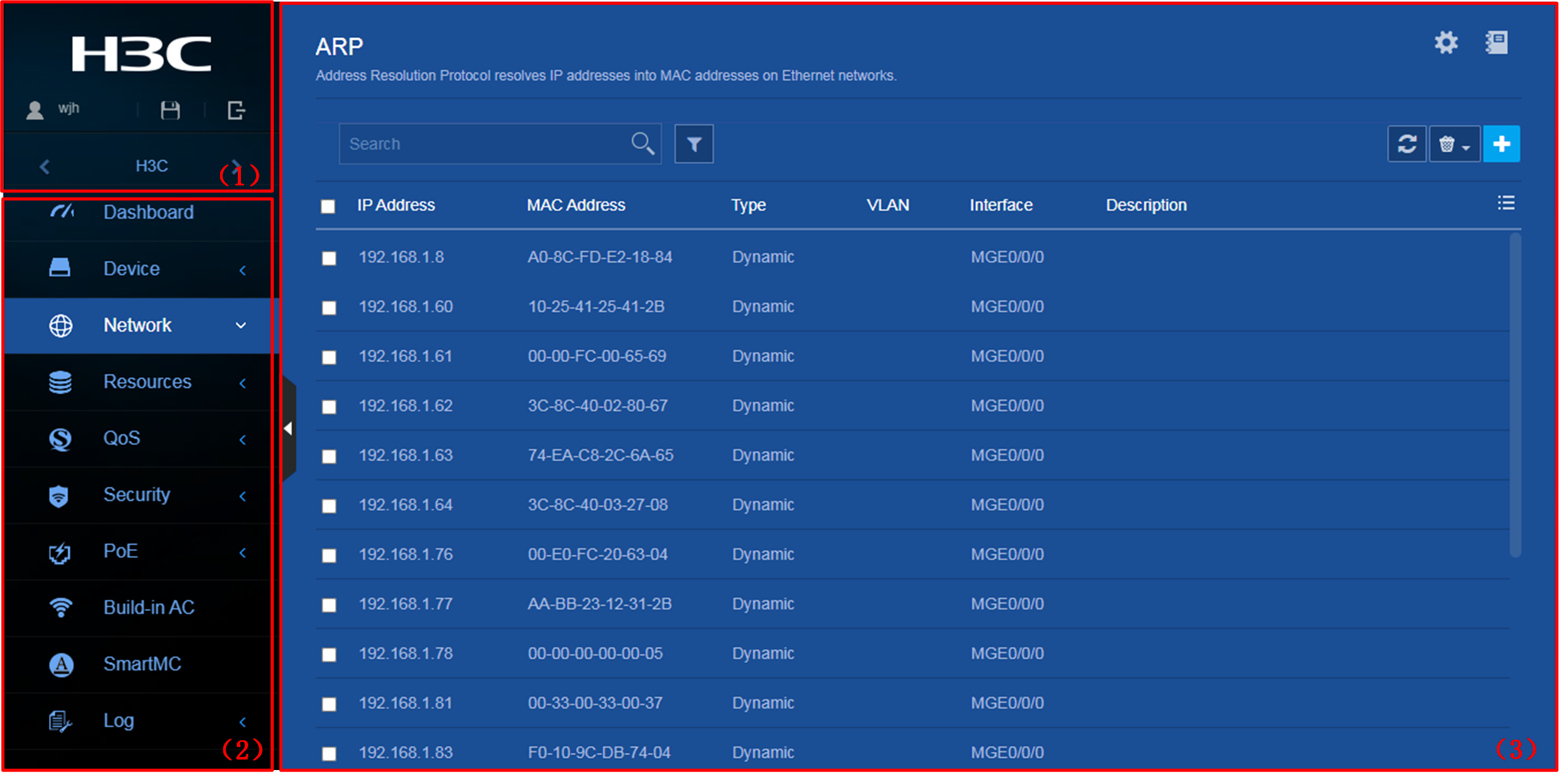
As shown in Figure 2, the Web interface contains the following areas:
|
Area |
Description |
|
(1) Banner and auxiliary area |
Contains the following items: · Basic information, including the Dahua logo, device name, and information about the current login user. · Basic management icons: ¡ Admin icon ¡ Logout icon ¡ Save icon |
|
(2) Navigation tree |
Organizes feature menus in a tree. |
|
(3) Content pane |
Displays information and provides an area for you to configure features. Depending on the content in this pane, the webpages include the following types: · Feature page—Contains functions or features that a feature module can provide (see "Using a feature page"). · Table page—Displays entries in a table (see "Using a table page"). · Configuration page—Contains parameters for you to configure a feature or function (see "Using a configuration page"). |
|
2) Navigation tree |
3) Content pane |
Types of webpages
Webpages include feature, table, and configuration pages. This section provides basic information about these pages. For more information about using the icons and buttons on the pages, see "Icons and buttons."
Using a feature page
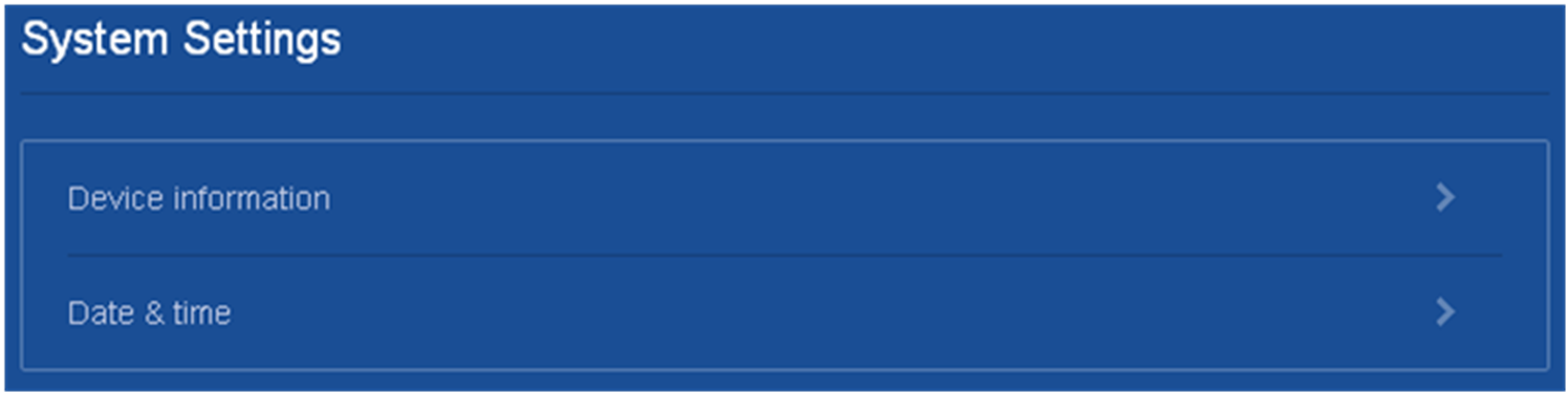
As shown in Figure 3, a feature page contains information about a feature module, including its table entry statistics, features, and functions. From a feature page, you can configure features provided by a feature module.
Using a table page
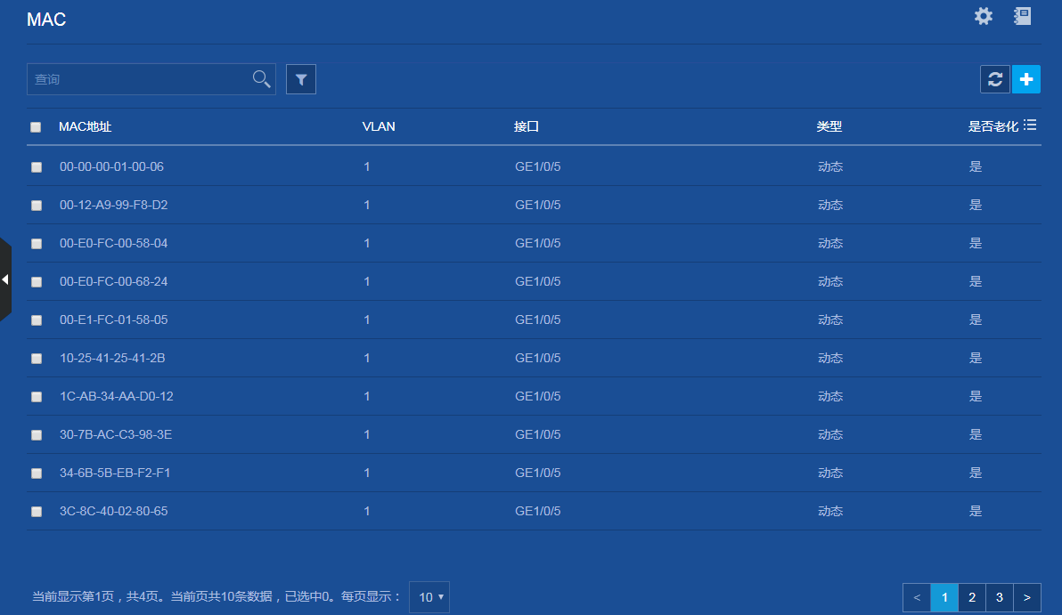
As shown in Figure 4, a table page displays entries in a table. To sort entries by a field in ascending or descending order, click the field. For example, click MAC Address to sort entries by MAC address.
Using a configuration page
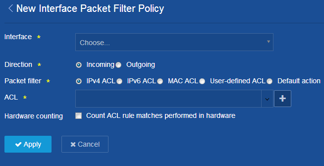
As shown in Figure 5, one configuration page contains all parameters for a configuration task. If a parameter must be configured on another page, the configuration page typically provides a link. You do not need to navigate to the destination page.
For example, you must use an ACL when you
configure a packet filter. If no ACLs are available when you perform the task,
you can click the Add icon ![]() to
create an ACL. In this situation, you do not need to navigate to the ACL
management page.
to
create an ACL. In this situation, you do not need to navigate to the ACL
management page.
Figure 5 Sample configuration page
Icons and buttons
Table 2 describes icons and buttons you can use to configure and manage the device.
|
Icon/button |
Icon/button name |
Task |
|
Help icons |
|
|
|
|
Help |
Obtain help information for a feature. |
|
|
Hint |
Obtain help information for a function or parameter. |
|
Counter icon |
|
|
|
|
Counter |
Identify the total number of table entries. |
|
Navigation icon |
|
|
|
|
Next |
Access the lower-level page to display information or configure settings. |
|
Status control icon |
|
|
|
|
Status control |
Control the enable status of the feature. · If ON is displayed, the feature is enabled. To disable the feature, click the button. · If OFF is displayed, the feature is disabled. To enable the feature, click the button. |
|
Search icons |
|
|
|
|
Search |
Enter a search expression in the search box, and then click this icon to perform a basic search. |
|
|
Advanced search |
Click this icon, and then enter a combination of criteria to perform an advanced search. |
|
Entry management icons |
|
|
|
|
Refresh |
Refresh table entries manually. |
|
|
Add |
· Add a new entry. · Confirm the addition of an entry and continue to add an additional entry. |
|
|
Detail |
Display or modify settings of an entry. This icon appears at the end of an entry when you hover over the entry. |
|
|
Delete |
Delete an entry. This icon appears at the end of an entry when you hover over the entry. |
|
|
Bulk-delete |
Select one or multiple entries, and then click this icon to delete the selected entries. |
|
|
Field selector |
Select fields to be displayed. |
|
Advanced settings icon |
|
|
|
|
Advanced settings |
Access the configuration page to configure settings. |
Performing basic tasks
This section describes the basic tasks that must be frequently performed when you configure or manage the device.
Saving the configuration
Typically, settings take effect immediately after you create them. However, the system does not automatically save the settings to the configuration file. They are lost when the device reboots.
To prevent settings from being lost, use one of the following methods to save the configuration:
· Click the Save icon ![]() in the left corner.
in the left corner.
· Select Device > Maintenance > Configuration to access the configuration management page.
Displaying or modifying settings of a table entry
2. Click the Detail
icon ![]() at the end of the entry.
at the end of the entry.
Rebooting the device
Reboot is required for some settings (for example, IRF) to take effect.
To reboot the device:
1. Save the configuration.
2. Select Device > Maintenance > Reboot.
3. On the reboot page, click the reboot button.
Feature navigator
Menu items and icons available to you depend on the user roles you have. By default, you can use any user roles to display information. To configure features, you must have the network-admin user role.
This chapter describes all menus available for the network-admin user role. The top-level menu includes Dashboard, Device, Network, Resources, QoS, Security, PoE, SmartMC, and Log. For each top menu, a navigator table is provided. Use the navigator tables to navigate to the pages for the tasks you want to perform.
For example:
· To change the default device name, select Device > Maintenance > Settings from the navigation tree.
· To delete an IPv4 ACL, select Resources > ACL > IPv4 from the navigation tree.
|
|
NOTE: In the navigator tables, a menu is in boldface if it has submenus. |
Dashboard menu
The dashboard menu provides an overview of the system and its running status, including:
· System log.
· Use rates of CPU and memory.
· Serial number of the device.
· Hardware version information.
This menu does not contain submenus.
Device menu
The features and functions provided the Device menu vary by switch. Use Table 3 to navigate to the tasks you can perform from the Device menu and obtain remarks about support for features and functions in the menu.
|
Menus |
Tasks |
Remarks |
|
Maintenance |
||
|
Settings |
· Configure basic device settings, including the device name, location, and contact. · Configure the system time settings. You can manually set the system time, or configure the device to obtain the UTC time from a trusted time source and calculate the system time. |
N/A |
|
Administrators |
· Create, modify, or delete user roles. · Create, modify, or delete user accounts. · Assign user roles to administrators for access control. · Manage passwords. |
· The following switches do not have the default account and do not support first login with a default username and password: ¡ ES5500 switch series. ¡ IE4300-12P-AC and IE4300-12P-PWR switches. · Login control with a weak password and first login with a default username and password are available only in Release 6318P01 and later. For more information, see "Password control." |
|
Configuration |
· Save the running configuration. · Import configuration and export the running configuration. · Display the running configuration. · Restore the factory-default configuration. |
N/A |
|
File System |
· Display storage medium information. · Display file and folder information. · Delete files. · Download files. |
N/A |
|
Upgrade |
· Upgrade software images. · Display software image lists, including: ¡ Current software images. ¡ Main and backup startup software images. |
You can use only .bin files to upgrade the following switches: · US300 switch series. · US500 switch series. · WAS6000 switch series. |
|
Diagnostics |
Collect diagnostic information used for system diagnostics and troubleshooting. |
N/A |
|
Reboot |
Reboot the device. |
N/A |
|
About |
Display basic device information, including: · Device name. · Serial number. · Version information. · Electronic label. · Legal statement. |
N/A |
|
Virtualization |
||
|
IRF |
· Set up an IRF fabric, including: ¡ Configure the IRF member ID. ¡ Configure the member priority. ¡ Configure the IRF domain ID. ¡ Bind physical interfaces to an IRF port. ¡ Activate IRF port configuration. · Display the IRF fabric topology. |
IRF is not supported on the following switches: · MS4100V2-EI switch series. · S1850-X switch series. · S1850V2-X switch series. · S1850V2-EI switch series. · US300 switch series. · US500 switch series. |
Network menu
Use Table 4 to navigate to the tasks you can perform from the Network menu.
Table 4 Network menu navigator
Resources menu
The Resources menu contains common resources that can be used by multiple features. For example, you can use an ACL both in a packet filter to filter traffic and in a QoS policy to match traffic.
Use Table 5 to navigate to the tasks you can perform from the Resources menu.
Table 5 Resources menu navigator
|
Menus |
Tasks |
|
ACLs |
|
|
IPv4 |
· Create, modify, or delete an IPv4 basic ACL. · Create, modify, or delete an IPv4 advanced ACL. |
|
IPv6 |
· Create, modify, or delete an IPv6 basic ACL. · Create, modify, or delete an IPv6 advanced ACL. |
|
Ethernet |
Create, modify, or delete an Ethernet frame header ACL. |
|
Time Range |
|
|
Time Range |
Create, modify, or delete a time range. |
|
SSL |
|
|
SSL |
· Create, modify, or delete an SSL client policy. · Create, modify, or delete an SSL server policy. |
|
Public key |
|
|
Public Key |
· Manage local asymmetric key pairs. · Manage peer host public keys. |
|
PKI |
|
|
PKI |
· Manage CA and local certificates. · Create, modify, or delete a PKI domain or PKI entity. |
|
Certificate Access Control |
· Create, modify, or delete a certificate access control policy. · Create, modify, or delete a certificate attribute group. |
|
|
NOTE: You can create ACLs from ACL pages or during the process of configuring a feature that uses ACLs. However, to modify or delete an ACL, you must access the ACL menu. |
QoS menu
Use Table 6 to navigate to the tasks you can perform from the QoS menu.
|
Menus |
Tasks |
|
QoS Policies |
· Create, modify, or delete interface QoS policies. · Create, modify, or delete VLAN QoS policies. · Create, modify, or delete global QoS policies. |
|
Hardware Queuing |
Modify hardware queuing configuration. |
|
Priority Mapping |
· Configure the port priority. · Configure the priority trust mode for a port. · Configure priority maps: ¡ Apply and reset the 802.1p-to-local priority map. ¡ Apply and reset the DSCP-to-802.1p priority map. ¡ Apply and reset the DSCP-to-DSCP priority map. |
|
Rate Limit |
Create, modify, or delete rate limit. |
Security menu
Use Table 7 to navigate to the tasks you can perform from the Security menu.
Table 7 Security menu navigator
|
Menus |
Tasks |
|
Packet Filter |
|
|
Packet Filter |
· Create, modify, or delete a packet filter for an interface, a VLAN, or the system. · Configure the default action for the packet filter. |
|
IP Source Guard |
Configure an interface-specific static IPv4 source guard binding. |
|
Access Control |
|
|
802.1X |
· Enable or disable 802.1X. · Configure the 802.1X authentication method. · Configure the port access control method. · Configure the port authorization state. · Configure the authentication ISP domain on a port. |
|
MAC Authentication |
· Enable or disable MAC authentication. · Configure the MAC authentication ISP domain. · Configure the username format. |
|
Port Security |
· Enable or disable port security · Configure the port security mode. · Configure the intrusion protection action. · Configure the NTK mode. · Configure secure MAC aging mode. |
|
Portal |
· Configure a portal authentication server. · Configure a portal Web server. · Configure a local portal Web server. · Create portal-free rules. · Create interface policies. |
|
Authentication |
|
|
ISP Domains |
Configure ISP domains. |
|
RADIUS |
Configure RADIUS schemes. |
|
TACACS |
Configure TACACS schemes. |
|
Local Users |
Configure local users. |
PoE menu
Use Table 8 to navigate to the tasks you can perform from the PoE menu.
|
Menus |
Tasks |
Remarks |
|
PoE |
· Configure the maximum PoE power and power alarm threshold for the device. · Enable or disable PoE on an interface. · Configure the maximum PoE power, power supply priority, PD description, and fault description for an interface. · Upgrade the PSE firmware. |
For the ES5500 switch series: · The ES4126P-PWR PXE device in an IRF 3.1 system supports PoE only when the ES5500 switch series are parent devices. · The PoE menu does not support enabling or disabling PoE on an interface or upgrading the PSE firmware. |
High Availability menu
Use Table 9 to navigate to the tasks you can perform from the High Availability menu.
Table 9 High Availability menu navigator
|
Menus |
Tasks |
Remarks |
|
Ethernet Ring |
· Configure ERPS. · Configure RRRP. |
· High availability is supported only on the following switches in R6332 or later: ¡ IE4300-12P-AC and IE4300-12P-PWR switches. ¡ MS4100V2-EI switch series. ¡ S1850-X switch series. ¡ S1850V2-EI switch series. ¡ S1850V2-X switch series. ¡ S5000V3-EI switch series. ¡ S5000V5-EI switch series. ¡ S5000E-X switch series. ¡ S5000X-EI switch series. ¡ US300 switch series. ¡ US500 switch series (except the US536-F-S switch). ¡ WAS6000 switch series. ¡ WS5810-WiNet switch series. ¡ WS5820-WiNet switch series. ¡ WS5850-WiNet switch series. |
SmartMC menu
Use Table 10 to navigate to the tasks you can perform from the SmartMC menu.
Table 10 SmartMC menu navigator
|
Menus |
Tasks |
Remarks |
|
Configuration Wizard |
Configure a device as the commander. |
· SmartMC is not supported on the following switches: ¡ ES5500 switch series. ¡ WS5810-WiNet switch series. ¡ WS5820-WiNet switch series. ¡ WS5850-WiNet switch series. ¡ WASS6000 switch series. · Only the S5000-EI switch series can act as both the commander and members in a SmartMC network. The other switch series can act as only members in a SmartMC network. |
|
Smart Management |
· Configure device roles. · Disable SmartMC. |
WiNet menu
Use Table 10 to navigate to the tasks you can perform from the WiNet menu.
Table 11 WiNet menu navigator
|
Menus |
Tasks |
Remarks |
|
Configuration Wizard |
Configure a device as the commander. |
· WiNet is supported on the following switches: ¡ WS5810-WiNet switch series. ¡ WS5820-WiNet switch series. ¡ WS5850-WiNet switch series. · In a WiNet network, the WS5810-WiNet switch series can act as only members, but the WS5820-WiNet and WS5850-WiNet switch series can act as the commander and members. |
|
Intelligent Management |
· Configure device roles. · Set the interval for collecting WiNet network typology information. · Configure the FTP server. · Configure an outbound interface for the WiNet network. · Configure automatic link aggregation. · Disable WiNet. |
|
|
Intelligent O&M |
· Configure WiNet groups. · Upgrade the startup software and configuration file on members. · Back up the configuration file on members. · Create a VLAN for members · Deploy configuration to members in bulk. · Intelligent port identification. · Monitor resources. · Replace faulty devices. |
|
|
Visibility |
· Manage the WiNet network topology. · Customize deice types. |
|
|
Intelligent Services |
Manage users. |
Log menu
Use Table 12 to navigate to the tasks you can perform from the Log menu.
|
Menus |
Tasks |
|
System Log |
· Display log information. · Query, collect, and delete log information. |
|
Settings |
· Configure log output destinations. · Enable or disable log output to the log buffer, and configure the maximum number of logs in the log buffer. · Configure the address and port number of log hosts. |
Device management
Settings
Access the Settings page to change the device name, location, and system time.
System time sources
Correct system time is essential to network management and communication. Configure the system time correctly before you run the device on the network.
The device can use the manually set system time, or obtain the UTC time from a time source on the network and calculate the system time.
· When using the locally set system time, the device uses the clock signals generated by its built-in crystal oscillator to maintain the system time.
If you change the time zone or daylight saving settings without changing the date or time, the device adjusts the system time based on the new settings.
· After obtaining the UTC time from a time source, the device uses the UTC time and the time zone and daylight saving settings to calculate the system time. Then, the device periodically synchronizes the UTC time and recalculates the system time.
If you change the time zone or daylight saving settings, the device recalculates the system time.
The system time calculated by using the UTC time from a time source is more precise.
Make sure the time zone and daylight saving setting are the same as the parameters of the place where the device resides.
If the system time does not change accordingly when the daylight saving period ends, refresh the Web interface.
Clock synchronization protocols
The device supports the following clock synchronization protocols:
· NTP—Network Time Protocol. NTP is typically used in large networks to dynamically synchronize time among network devices. It provides higher clock accuracy than manual system time configuration.
· SNTP—Simple NTP, a simpler implementation of NTP. SNTP uses the same packet formats and exchange procedures as NTP. However, SNTP simplifies the clock synchronization procedure. Compared with NTP, SNTP uses less resources and implements clock synchronization in shorter time, but it provides lower time accuracy.
NTP/SNTP operating modes
NTP supports two operating modes: client/server mode and symmetric active/passive mode. The device can act only as a client in client/server mode or the active peer in symmetric active/passive mode.
SNTP supports only the client/server mode. The device can act only as a client.
Table 13 NTP/SNTP operating modes
|
Mode |
Operating process |
Principle |
Application scenario |
|
Client/server |
1. A client sends a clock synchronization message to the NTP servers. 2. Upon receiving the message, the servers automatically operate in server mode and send a reply. 3. If the client is synchronized to multiple time servers, it selects an optimal clock and synchronizes its local clock to the optimal reference source. You can configure multiple time servers for a client. This operating mode requires that you specify the IP address of the NTP server on the client. |
A client can synchronize to a server, but a server cannot synchronize to a client. |
This mode is intended for scenarios where devices of a higher stratum synchronize to devices with a lower stratum. |
|
Symmetric active/passive |
4. A symmetric active peer periodically sends clock synchronization messages to a symmetric passive peer. 5. The symmetric passive peer automatically operates in symmetric passive mode and sends a reply. 6. If the symmetric active peer can be synchronized to multiple time servers, it selects an optimal clock and synchronizes its local clock to the optimal reference source. This operating mode requires you specify the IP address of the symmetric passive peer on the symmetric active peer. |
A symmetric active peer and a symmetric passive peer can be synchronized to each other. If both of them are synchronized, the peer with a higher stratum is synchronized to the peer with a lower stratum. |
This mode is most often used between servers with the same stratum to operate as a backup for one another. If a server fails to communicate with all the servers of a lower stratum, the server can still synchronize to the servers of the same stratum. |
NTP/SNTP time source authentication
The time source authentication function enables the device to authenticate the received NTP or SNTP packets. This function ensures that the device obtains the correct GMT.
For a successful authentication in client/server mode, you must enable authentication on both the client and server, and configure the same key ID and key on them.
For a successful authentication in symmetric active/passive mode, you must enable authentication on both the active and passive peers, and configure the same key ID and key on them.
Administrators
An administrator configures and manages the device from the following aspects:
· User account management—Manages user account information and attributes (for example, username and password).
· Role-based access control—Manages user access permissions by user role.
· Password control—Manages user passwords and controls user login status based on predefined policies.
The service type of an administrator can be SSH, Telnet, FTP, HTTP, HTTPS, or terminal.
User account management
A user account on the device manages attributes for users who log in to the device with the same username. The attributes include the username, password, services, and password control parameters.
Role-based access control
Assign users user roles to control the users' access to functions and system resources. Assigning permissions to a user role includes the following:
· Defines a set of rules to determine accessible or inaccessible functions for the user role.
· Configures resource access policies to specify which interfaces, VLANs, and VRF instances are accessible to the user role.
To configure a function related to a resource (an interface or VLAN), a user role must have access to both the function and the resource.
User role rules
User role rules permit or deny access to specific functions. On the Web interface, a user role controls access to specific elements on webpages. The webpages are arranged into tree-structured Web menus. You can control access to Web menus based on the following attributes:
· Read—Web menus that display configuration and maintenance information.
· Write—Web menus that configure the feature in the system.
· Execute—Web menus that execute specific functions.
A user role can access the set of permitted Web menus specified in the user role rules.
Resource access policies
Resource access policies control access of user roles to system resources and include the following types:
· Interface policy—Controls access to interfaces.
· VLAN policy—Controls access to VLANs.
You can perform the following tasks on an accessible interface or VLAN:
· Create or remove the interface or VLAN.
· Configure attributes for the interface or VLAN.
· Apply the interface or VLAN to other parameters.
Predefined user roles
The system provides predefined user roles. These user roles have access to all system resources (interfaces, VLANs, and VRF instances). Their access permissions differ.
If the predefined user roles cannot meet the access requirements, you can define new user roles to control the access permissions for users.
|
|
IMPORTANT: The security-audit user role has access only to security log menus. Security log menus are not supported on the current Web interface, so do not assign the security-audit user role to any users. |
Assigning user roles
Depending on the authentication method, user role assignment has the following methods:
· Local authorization—If the user passes local authorization, the device assigns the user roles specified in the local user account.
· Remote authorization—If the user passes remote authorization, the remote AAA server assigns the user roles specified on the server.
A user who fails to obtain a user role is logged out of the device.
If multiple user roles are assigned to a user, the user can use the collection of functions and resources accessible to all the user roles.
Password control
Password control allows you to implement the following features:
· Manage login and super password setup, expirations, and updates for device management users.
· Control user login status based on predefined policies.
Local users are divided into two types: device management users and network access users. This feature applies only to device management users.
Minimum password length
You can define the minimum length of user passwords. If a user enters a password that is shorter than the minimum length, the system rejects the password.
Password composition policy
A password can be a combination of characters from the following types:
· Uppercase letters A to Z.
· Lowercase letters a to z.
· Digits 0 to 9.
· Special characters. See Table 14.
|
Character name |
Symbol |
Character name |
Symbol |
|
Ampersand sign |
& |
Apostrophe |
' |
|
Asterisk |
* |
At sign |
@ |
|
Back quote |
` |
Back slash |
\ |
|
Blank space |
N/A |
Caret |
^ |
|
Colon |
: |
Comma |
, |
|
Dollar sign |
$ |
Dot |
. |
|
Equal sign |
= |
Exclamation point |
! |
|
Left angle bracket |
< |
Left brace |
{ |
|
Left bracket |
[ |
Left parenthesis |
( |
|
Minus sign |
- |
Percent sign |
% |
|
Plus sign |
+ |
Pound sign |
# |
|
Quotation marks |
" |
Right angle bracket |
> |
|
Right brace |
} |
Right bracket |
] |
|
Right parenthesis |
) |
Semi-colon |
; |
|
Slash |
/ |
Tilde |
~ |
|
Underscore |
_ |
Vertical bar |
| |
Depending on the system's security requirements, you can set the minimum number of character types a password must contain and the minimum number of characters for each type, as shown in Table 15.
Table 15 Password composition policy
|
Password combination level |
Minimum number of character types |
Minimum number of characters for each type |
|
Level 1 |
One |
One |
|
Level 2 |
Two |
One |
|
Level 3 |
Three |
One |
|
Level 4 |
Four |
One |
In non-FIPS mode, all the combination levels are available for a password. In FIPS mode, only the level 4 combination is available for a password.
When a user sets or changes a password, the system checks if the password meets the combination requirement. If the password does not meet the requirement, the operation fails.
Password complexity checking policy
A less complicated password such as a password containing the username or repeated characters is more likely to be cracked. For higher security, you can configure a password complexity checking policy to ensure that all user passwords are relatively complicated. With such a policy configured, when a user configures a password, the system checks the complexity of the password. If the password is complexity-incompliant, the configuration will fail.
You can apply the following password complexity requirements:
· A password cannot contain the username or the reverse of the username. For example, if the username is abc, a password such as abc982 or 2cba is not complex enough.
· A character or number cannot be included three or more times consecutively. For example, password a111 is not complex enough.
Login control with a weak password
The system checks for weak passwords for Telnet, SSH, HTTP, or HTTPS device management users. A password is weak if it does not meet the following requirements:
· Password composition restriction.
· Minimum password length restriction.
· Username checking.
By default, the system displays a message about a weak password but does not force the user to change it. To improve the device security, you can enable the mandatory weak password change feature, which forces the users to change the identified weak passwords. The users can log in to the device only after their passwords meet the password requirements.
First login with a default username and password
The factory defaults contain a default username and password. If the device starts up with factory defaults, Telnet, SSH, HTTP, or HTTPS device management users must change the default password at first login before they can access the system.
Password updating
This function allows you to set the minimum interval at which users can change their passwords. If a user logs in to change the password but the time passed since the last change is less than this interval, the system denies the request. For example, if you set this interval to 48 hours, a user cannot change the password twice within 48 hours.
The set minimum interval is not effective when a user is prompted to change the password at the first login or after its password aging time expires.
Password expiration
Password expiration imposes a lifecycle on a user password. After the password expires, the user needs to change the password.
If a user enters an expired password when logging in, the system displays an error message. The user is prompted to provide a new password and to confirm it by entering it again. The new password must be valid, and the user must enter exactly the same password when confirming it.
Telnet users, SSH users, and console users can change their own passwords. The administrator must change passwords for FTP users.
Early notice on pending password expiration
When a user logs in, the system checks whether the password will expire in a time equal to or less than the specified notification period. If so, the system notifies the user when the password will expire and provides a choice for the user to change the password. If the user sets a new password that is complexity-compliant, the system records the new password and the setup time. If the user chooses not to change the password or the user fails to change it, the system allows the user to log in using the current password.
Telnet users, SSH users, and console users can change their own passwords. The administrator must change passwords for FTP users.
Login with an expired password
You can allow a user to log in a certain number of times within a period of time after the password expires. For example, if you set the maximum number of logins with an expired password to 3 and the time period to 15 days, a user can log in three times within 15 days after the password expires.
Password history
With this feature enabled, the system stores passwords that a user has used. When a user changes the password, the system checks the new password against the current password and those stored in the password history records. The new password must be different from the current one and those stored in the history records by at least four characters. The four characters must be different from one another. Otherwise, the system will display an error message, and the password will not be changed.
You can set the maximum number of history password records for the system to maintain for each user. When the number of history password records exceeds your setting, the most recent record overwrites the earliest one.
Current login passwords of device management users are not stored in the password history, because a device management user password is saved in cipher text and cannot be recovered to a plaintext password.
Login attempt limit
Limiting the number of consecutive login failures can effectively prevent password guessing.
Login attempt limit takes effect on FTP and VTY users. It does not take effect on the following types of users:
· Nonexistent users (users not configured on the device).
· Users logging in to the device through console ports.
If a user fails to use a user account to log in after making the maximum number of consecutive attempts, login attempt limit takes the following actions:
· Adds the user account and the user's IP address to the password control blacklist. This account is locked for only this user. Other users can still use this account, and the blacklisted user can use other user accounts.
· Limits the user and user account in any of the following ways:
¡ Disables the user account until the account is manually removed from the password control blacklist.
¡ Allows the user to continue using the user account. The user's IP address and user account are removed from the password control blacklist when the user uses this account to successfully log in to the device.
¡ Disables the user account for a period of time.
The user can use the account to log in when either of the following conditions exist:
- The locking timer expires.
- The account is manually removed from the password control blacklist before the locking timer expires.
Maximum account idle time
You can set the maximum account idle time for user accounts. When an account is idle for this period of time since the last successful login, the account becomes invalid.
IRF
The Intelligent Resilient Framework (IRF) technology creates a large IRF fabric from multiple devices to provide data center class availability and scalability. IRF virtualization technology offers processing power, interaction, unified management, and uninterrupted maintenance of multiple devices.
An IRF fabric provides a single point of management. You can access an IRF fabric from any member device to configure and manage all the members as if they were interface modules on one node. Any settings will be issued to all member devices in the IRF fabric.
The following information describes the concepts that you might encounter when you use IRF.
IRF member roles
IRF uses two member roles: master and standby (also called subordinate).
When devices form an IRF fabric, they elect a master to manage and control the IRF fabric. All the other members process services while backing up the master. When the master device fails, the other devices elect a new master automatically.
IRF port
An IRF port is a logical interface for the connection between IRF member devices. Every IRF-capable device supports two IRF ports: IRF-port 1 and IRF-port 2.
To use an IRF port, you must bind a minimum of one physical port to it. The physical ports assigned to an IRF port form an aggregate IRF link automatically.
When you connect two neighboring IRF members, you must connect the physical interfaces of IRF-port 1 on one member to the physical interfaces of IRF-port 2 on the other.
IRF physical port
IRF physical ports connect IRF member devices and must be bound to an IRF port. They forward IRF protocol packets and data packets between IRF member devices.
You can use the following ports for IRF links:
· Fiber ports—XGE1/0/49 and XGE1/0/50.
· Copper ports—XGE1/0/51 and XGE1/0/52.
To connect the fiber ports, you must use fiber transceiver modules and fibers.
To connect the copper ports, you can use Ethernet cables.
You can assign fiber and copper ports to the same IRF port. However, the ports at the two ends of an IRF link must be the same type.
IRF domain ID
One IRF fabric forms one IRF domain. IRF domain IDs uniquely identify IRF fabrics and prevents IRF fabrics from interfering with one another.
IRF split and IRF merge
IRF split occurs when an IRF fabric breaks up into two or more IRF fabrics because of IRF link failures.
IRF merge occurs when two split IRF fabrics reunite or when two independent IRF fabrics are united.
Member priority
Member priority determines the possibility of a member device to be elected the master. A member with higher priority is more likely to be elected the master.
The default member priority is 1. You can change the member priority of a device to affect the master election result.
Network services features
Link aggregation
Ethernet link aggregation bundles multiple physical Ethernet links into one logical link, called an aggregate link. Link aggregation has the following benefits:
· Increased bandwidth beyond the limits of any single link. In an aggregate link, traffic is distributed across the member ports.
· Improved link reliability. The member ports dynamically back up one another. When a member port fails, its traffic is automatically switched to other member ports.
Aggregation group
Link bundling is implemented through interface bundling. An aggregation group is a group of Ethernet interfaces bundled together. These Ethernet interfaces are called member ports of the aggregation group. Each aggregation group has a corresponding logical interface (called an aggregate interface).
When you create an aggregate interface, the device automatically creates an aggregation group of the same type and number as the aggregate interface. For example, when you create Layer 2 aggregate interface 1, Layer 2 aggregation group 1 is created.
An aggregate interface can be one of the following types:
· Layer 2—The member ports in a Layer 2 aggregation group can only be Layer 2 Ethernet interfaces.
· Layer 3—The member ports in a Layer 3 aggregation group can only be Layer 3 Ethernet interfaces.
The port rate of an aggregate interface equals the total rate of its Selected member ports. Its duplex mode is the same as that of the Selected member ports.
Aggregation states of member ports in an aggregation group
A member port in an aggregation group can be in any of the following aggregation states:
· Selected—A Selected port can forward traffic.
· Unselected—An Unselected port cannot forward traffic.
Operational key
When aggregating ports, the system automatically assigns each port an operational key based on port information, such as port rate and duplex mode. Any change to this information triggers a recalculation of the operational key.
In an aggregation group, all Selected ports have the same operational key.
Attribute configurations
To become a Selected port, a member port must have the same attribute configurations as the aggregate interface.
|
Feature |
Considerations |
|
Port isolation |
Indicates whether the port has joined an isolation group, and the isolation group to which the port belongs. |
|
VLAN |
VLAN attribute configurations include: · Permitted VLAN IDs. · PVID. · VLAN tagging mode. |
Link aggregation modes
An aggregation group operates in one of the following modes:
· Static—Static aggregation is stable. An aggregation group in static mode is called a static aggregation group. The aggregation states of the member ports in a static aggregation group are not affected by the peer ports.
· Dynamic—An aggregation group in dynamic mode is called a dynamic aggregation group. The local system and the peer system automatically maintain the aggregation states of the member ports through LACP, which reduces the administrators' workload.
Global load sharing modes
In a link aggregation group, traffic can be load shared across the Selected ports based on any of the following modes:
· Per-flow load sharing—Distributes traffic on a per-flow basis. The load sharing mode classifies packets into flows and forwards packets of the same flow on the same link. This mode can be one of or a combination of the following traffic classification criteria:
¡ Source IP.
¡ Destination IP.
¡ Source MAC.
¡ Destination MAC.
· Per-packet load sharing—Distributes traffic on a per-packet basis.
· Automatic load sharing—Automatically selects a load sharing mode depending on the packet type.
Storm control
Storm control compares broadcast, multicast, and unknown unicast traffic regularly with their respective traffic thresholds on an Ethernet interface. For each type of traffic, storm control provides a lower threshold and an upper threshold.
Depending on your configuration, when a particular type of traffic exceeds its upper threshold, the interface performs either of the following tasks:
· No action—Does not perform any actions on the interface.
· Block—Blocks this type of traffic and forwards other types of traffic. Even though the interface does not forward the blocked traffic, it still counts the traffic. When the blocked traffic drops below the lower threshold, the interface begins to forward the traffic.
· Shutdown—The interface goes down automatically and stops forwarding any traffic. When the blocked traffic drops below the lower threshold, the interface does not automatically come up. To bring up the interface, manually bring up the interface or disable the storm control function.
You can configure an Ethernet interface to output threshold event traps and log messages when monitored traffic meets one of the following conditions:
· Exceeds the upper threshold.
· Drops below the lower threshold.
Port isolation
The port isolation feature isolates Layer 2 traffic for data privacy and security without using VLANs.
Ports in an isolation group cannot communicate with each other. However, they can communicate with ports outside the isolation group.
VLAN
The Virtual Local Area Network (VLAN) technology breaks a LAN down into multiple logical LANs, which is called VLANs. Each VLAN is a broadcast domain. Hosts in the same VLAN can directly communicate with one another. Hosts in different VLANs are isolated from one another at Layer 2.
Port-based VLANs
Port-based VLANs group VLAN members by port. A port forwards packets from a VLAN only after it is assigned to the VLAN.
You can configure a port as an untagged or tagged port of a VLAN.
· To configure the port as an untagged port of a VLAN, assign it to the untagged port list of the VLAN. The untagged port of a VLAN forwards packets from the VLAN without VLAN tags.
· To configure the port as a tagged port of a VLAN, assign it to the tagged port list of the VLAN. The tagged port of a VLAN forwards packets from the VLAN with VLAN tags.
You can configure the link type of a port as access, trunk, or hybrid. Ports of different link types use different VLAN tag handling methods.
· Access—An access port can forward packets from only one VLAN and send them untagged. Assign an access port to only the untagged port list of a VLAN.
· Trunk—A trunk port can forward packets from multiple VLANs. Except packets from the port VLAN ID (PVID), packets sent out of a trunk port are VLAN-tagged. Assign a trunk port to the untagged port list of the PVID of the port, and to the tagged port lists of other VLANs.
· Hybrid—A hybrid port can forward packets from multiple VLANs. You can assign a hybrid port to the untagged port lists of some VLANs, and to the tagged port lists of other VLANs. An untagged hybrid port of a VLAN forwards packets from the VLAN without VLAN tags. A tagged hybrid port of a VLAN forwards packets from the VLAN with VLAN tags.
VLAN interface
For hosts of different VLANs to communicate at Layer 3, you can use VLAN interfaces. VLAN interfaces are virtual interfaces used for Layer 3 communication between different VLANs. They do not exist as physical entities on devices. For each VLAN, you can create one VLAN interface and assign an IP address to it. The VLAN interface acts as the gateway of the VLAN to forward packets destined for another IP subnet.
Voice VLAN
A voice VLAN is used for transmitting voice traffic. The device can configure QoS parameters for voice packets to ensure higher transmission priority of the voice packets.
OUI addresses
A device identifies voice packets based on their source MAC addresses. A packet whose source MAC address complies with an Organizationally Unique Identifier (OUI) address of the device is regarded as a voice packet. OUI addresses are the logical AND results of MAC addresses and OUI masks.
The following table shows the default OUI addresses.
|
Number |
OUI address |
Vendor |
|
1 |
0001-E300-0000 |
Siemens phone |
|
2 |
0003-6B00-0000 |
Cisco phone |
|
3 |
0004-0D00-0000 |
Avaya phone |
|
4 |
000F-E200-0000 |
H3C Aolynk phone |
|
5 |
0060-B900-0000 |
Philips/NEC phone |
|
6 |
00D0-1E00-0000 |
Pingtel phone |
|
7 |
00E0-7500-0000 |
Polycom phone |
|
8 |
00E0-BB00-0000 |
3Com phone |
QoS priority setting mode for voice traffic
The QoS priority settings carried in voice traffic include the CoS and DSCP values. You can configure the device to trust or modify the QoS priority settings for voice traffic. If the device trusts the QoS priority settings in incoming voice VLAN packets, the device does not modify their CoS and DSCP values.
Voice VLAN assignment modes
A port can be assigned to a voice VLAN automatically or manually.
Automatic mode
When an IP phone is powered on, it sends out protocol packets. After receiving these protocol packets, the device uses the source MAC address of the protocol packets to match its OUI addresses. If the match succeeds, the device performs the following operations:
· Assigns the receiving port of the protocol packets to the voice VLAN.
· Issues ACL rules and sets the packet precedence.
· Starts the voice VLAN aging timer.
If no voice packet is received from the port before the aging timer expires, the device will remove the port from the voice VLAN. The aging timer is also configurable.
Manual mode
You must manually assign the port that connects to the IP phone to a voice VLAN. The device uses the source MAC address of the received voice packets to match its OUI addresses. If the match succeeds, the device issues ACL rules and sets the packet precedence.
Security mode and normal mode of voice VLANs
Depending on the incoming packet filtering mechanisms, a voice VLAN-enabled port can operate in one of the following modes:
· Normal mode—The port receives voice-VLAN-tagged packets and forwards them in the voice VLAN without examining their MAC addresses. If the PVID of the port is the voice VLAN and the port operates in manual VLAN assignment mode, the port forwards all the received untagged packets in the voice VLAN.
· Security mode—The port uses the source MAC addresses of the received packets to match the OUI addresses of the device. Packets that fail the match will be dropped.
MAC
An Ethernet device uses a MAC address table to forward frames. A MAC address entry includes a destination MAC address, an outgoing interface (or egress RB), and a VLAN ID. When the device receives a frame, it uses the destination MAC address of the frame to look for a match in the MAC address table.
· The device forwards the frame out of the outgoing interface in the matching entry if a match is found.
· The device floods the frame in the VLAN of the frame if no match is found.
Types of MAC address entries
A MAC address table can contain the following types of entries:
· Dynamic entries—A dynamic entry can be manually configured or dynamically learned to forward frames with a specific destination MAC address out of the associated interface. A dynamic entry might age out. A manually configured dynamic entry has the same priority as a dynamically learned one.
· Static entries—A static entry is manually added to forward frames with a specific destination MAC address out of the associated interface, and it never ages out. A static entry has higher priority than a dynamically learned one.
· Blackhole entries—A blackhole entry is manually configured and never ages out. A blackhole entry is configured for filtering out frames with a specific source or destination MAC address. For example, to block all frames destined for or sourced from a user, you can configure the MAC address of the user as a blackhole MAC address entry.
· Security entries—A security entry can be manually configured or dynamically learned to forward frames with a specific MAC address out of the associated interface. A security entry never ages out.
Aging timer for dynamic MAC address entries
For security and efficient use of table space, the MAC address table uses an aging timer for dynamic entries learned on all interfaces. If a dynamic MAC address entry is not updated before the aging timer expires, the device deletes the entry. This aging mechanism ensures that the MAC address table can promptly update to accommodate latest network topology changes.
A stable network requires a longer aging interval, and an unstable network requires a shorter aging interval.
An aging interval that is too long might cause the MAC address table to retain outdated entries. As a result, the MAC address table resources might be exhausted, and the MAC address table might fail to update its entries to accommodate the latest network changes.
An interval that is too short might result in removal of valid entries, which would cause unnecessary floods and possibly affect the device performance.
To reduce floods on a stable network, set a long aging timer or disable the timer to prevent dynamic entries from unnecessarily aging out. Reducing floods improves the network performance. Reducing flooding also improves the security because it reduces the chances for a data frame to reach unintended destinations.
MAC address learning
MAC address learning is enabled by default. To prevent the MAC address table from being saturated when the device is experiencing attacks, disable MAC address learning. For example, you can disable MAC address learning to prevent the device from being attacked by a large amount of frames with different source MAC addresses.
When global MAC address learning is enabled, you can disable MAC address learning on a single interface.
You can also configure the MAC learning limit on an interface to limit the MAC address table size. A large MAC address table will degrade forwarding performance. When the limit is reached, the interface stops learning any MAC addresses. You can also configure whether to forward frames whose source MAC address is not in the MAC address table.
STP
Spanning tree protocols perform the following tasks:
· Prune the loop structure into a loop-free tree structure for a Layer 2 network by selectively blocking ports.
· Maintain the tree structure for the live network.
Spanning tree protocols include STP, RSTP, and MSTP:
· STP—Defined in IEEE 802.1d.
· RSTP—Defined in IEEE 802.1w. RSTP achieves rapid network convergence by allowing a newly elected root port or designated port to enter the forwarding state much faster than STP.
· PVST—PVST allows every VLAN to have its own spanning tree, which increases usage of links and bandwidth.
· MSTP—Defined in IEEE 802.1s. MSTP overcomes the limitations of STP and RSTP. It supports rapid network convergence and allows data flows of different VLANs to be forwarded along separate paths. This provides a better load sharing mechanism for redundant links.
Spanning tree modes
The spanning tree modes include:
· STP mode—All ports of the device send STP BPDUs. Select this mode when the peer device of a port supports only STP.
· RSTP mode—All ports of the device send RSTP BPDUs. A port in this mode automatically transits to the STP mode when it receives STP BPDUs from a peer device. The port does not transit to the MSTP mode when it receives MSTP BPDUs from a peer device.
· PVST mode—All ports of the device send PVST BPDUs. Each VLAN maintains a spanning tree. In a network, the number of spanning trees maintained by all devices equals the number of PVST-enabled VLANs multiplied by the number of PVST-enabled ports. If the number of spanning trees exceeds the capacity of the network, device CPUs become overloaded, packet forwarding is interrupted, and the network becomes unstable. The number of spanning trees that a device can maintain varies by device model.
· MSTP mode—All ports of the device send MSTP BPDUs. A port in this mode automatically transits to the STP mode when it receives STP BPDUs from a peer device. The port does not transit to the RSTP mode when it receives RSTP BPDUs from a peer device.
MSTP basic concepts
MSTP divides a switched network into multiple spanning tree regions (MST regions). MSTP maintains multiple independent spanning trees in an MST region, and each spanning tree is mapped to specific VLANs. Such a spanning tree is referred to as a multiple spanning tree instance (MSTI). The common spanning tree (CST) is a single spanning tree that connects all MST regions in the switched network. An internal spanning tree (IST) is a spanning tree that runs in an MST region. It is also called MSTI 0, a special MSTI to which all VLANs are mapped by default. The common and internal spanning tree (CIST) is a single spanning tree that connects all devices in the switched network. It consists of the ISTs in all MST regions and the CST.
Devices in an MST region have the following characteristics:
· A spanning tree protocol enabled.
· Same region name.
· Same VLAN-to-instance mapping configuration.
· Same MSTP revision level.
· Physically linked together.
Port roles
Spanning tree calculation involves the following port roles:
· Root port—Forwards data for a non-root bridge to the root bridge. The root bridge does not have any root port.
· Designated port—Forwards data to the downstream network segment or device.
· Alternate port—Serves as the backup port for a root port or master port. When the root port or master port is blocked, the alternate port takes over.
· Backup port—Serves as the backup port of a designated port. When the designated port is invalid, the backup port becomes the new designated port. A loop occurs when two ports of the same spanning tree device are connected, so the device blocks one of the ports. The blocked port acts as the backup.
· Master port—Serves as a port on the shortest path from the local MST region to the common root bridge. The master port is not always located on the regional root. It is a root port on the IST or CIST and still a master port on the other MSTIs.
STP calculation involves root ports, designated ports, and alternate ports. RSTP calculation involves root ports, designated ports, alternate ports, and backup ports. MSTP calculation involves all port roles.
Port states
RSTP and MSTP define the following port states:
|
State |
Description |
|
Forwarding |
The port receives and sends BPDUs, and forwards user traffic. |
|
Learning |
The port receives and sends BPDUs, but does not forward user traffic. Learning is an intermediate port state. |
|
Discarding |
The port receives and sends BPDUs, but does not forward user traffic. |
STP defines the following port states: Disabled, Blocking, Listening, Learning, and Forwarding. The Disabled, Blocking, and Listening states correspond to the Discarding state in RSTP and MSTP.
Edge port
In the spanning tree calculation, to avoid a temporary loop, a port takes a period of time to enter the forwarding state after it is enabled. Because a port directly connecting to a user terminal network does not participate in topology calculation, you can configure the port as an edge port. After an edge port is enabled, it directly enters the forwarding state to implement fast network convergence.
STP timers
The most important timing parameters in STP calculation are forward delay, hello time, and max age.
· Forward delay—The forward delay is the delay time for port state transition. The newly elected root ports or designated ports must go through the listening and learning states before they transit to the forwarding state. This requires twice the forward delay time and allows the new configuration BPDU to propagate throughout the network.
· Hello time—The device sends configuration BPDUs at the hello time interval to the neighboring devices to ensure that the paths are fault-free. If the device does not receive configuration BPDUs within the timeout period, it recalculates the spanning tree. The formula for calculating the timeout period is timeout period = timeout factor × 3 × hello time. The timeout factor is 3 by default.
· Max age—The device uses the max age to determine whether a stored configuration BPDU has expired and discards it if the max age is exceeded.
To ensure a fast topology convergence, make sure the timer settings meet the following formulas:
· 2 × (forward delay – 1 second) ≥ max age
· Max age ≥ 2 × (hello time + 1 second)
Standards for the default path cost calculation
The following three standards are available for the default path cost calculation. On a spanning tree network with devices from multiple vendors, you can specify a standard for the device to use in automatic calculation for the default path cost for compatibility with devices from other vendors.
· dot1d-1998—The device calculates the default path cost for ports based on IEEE 802.1d-1998.
· dot1t—The device calculates the default path cost for ports based on IEEE 802.1t.
· legacy—The device calculates the default path cost for ports based on a private standard.
BPDU transmission rate
The maximum number of BPDUs a port can send within each hello time is the BPDU transmission rate. The higher the BPDU transmission rate, the more BPDUs are sent within each hello time, and the more system resources are used. By setting an appropriate BPDU transmission rate, you can limit the rate at which the port sends BPDUs. Setting an appropriate rate also prevents spanning tree protocols from using excessive network resources when the network topology changes.
To prevent an edge port from affecting the spanning tree topology stability of the core network when it receives BPDUs, you can enable BPDU guard. With BPDU guard enabled on an edge port, the edge port is shut down when it receives BPDUs, and the system notifies the NMS that the port has been shut down by the spanning tree protocol. The shutdown port will be reactivated again after a period of time.
Maximum hops of an MST region
Restrict the region size by setting the maximum hops of an MST region. The hop limit configured on the regional root bridge is used as the hop limit for the MST region.
Configuration BPDUs sent by the regional root bridge always have a hop count set to the maximum value. When a device receives this configuration BPDU, it decrements the hop count by one, and uses the new hop count in the BPDUs that it propagates. When the hop count of a BPDU reaches zero, it is discarded by the device that received it. Devices beyond the reach of the maximum hops can no longer participate in spanning tree calculations, so the size of the MST region is limited.
Spanning tree protection features
The spanning tree protocol supports multiple protection features to ensure the stability of the spanning tree topology.
· Loop guard—When link congestion or unidirectional link failures occur on the spanning tree network, a blocked port might transit to the forwarding state. As a result, loops occur. The initial state of a loop guard-enabled port is discarding in every MSTI. When the port receives BPDUs in an MSTI, it transits its state only in the MSTI. Otherwise, it stays in the discarding state to prevent temporary loops.
· Root guard—Due to possible configuration errors or malicious attacks in the network, the legal root bridge might receive a configuration BPDU with a higher priority. Another device supersedes the current legal root bridge, causing an undesired change of the network topology. The traffic that should go over high-speed links is switched to low-speed links, resulting in network congestion. To prevent this situation, MSTP provides the root guard feature. If root guard is enabled on a port of a root bridge, this port plays the role of designated port on all MSTIs. After this port receives a configuration BPDU with a higher priority from an MSTI, it immediately sets that port to the listening state in the MSTI and does not forward the received configuration BPDU. This is equivalent to disconnecting the link connected to this port in the MSTI. If the port receives no BPDUs with a higher priority within a certain period of time, it reverts to its original state.
· Port role restriction—The bridge ID change of a device in the user access network might cause a change to the spanning tree topology in the core network. To avoid this problem, you can enable port role restriction on a port. With this feature enabled, when the port receives a superior BPDU, it becomes an alternate port rather than a root port.
· TC-BPDU transmission restriction—The topology change to the user access network might cause the forwarding address changes to the core network. When the user access network topology is unstable, the user access network might affect the core network. To avoid this problem, you can enable TC-BPDU transmission restriction on a port. With this feature enabled, when the port receives a TC-BPDU, it does not forward the TC-BPDU to other ports.
· TC-BPDU guard—When a device receives topology change (TC) BPDUs (the BPDUs that notify devices of topology changes), it flushes its forwarding address entries. If someone uses TC-BPDUs to attack the device, the device will receive a large number of TC-BPDUs within a short time. Then, the device is busy with forwarding address entry flushing. This affects network stability. TC-BPDU guard allows you to set the maximum number of immediate forwarding address entry flushes performed within the specified period of time after the device receives the first TC-BPDU. For TC-BPDUs received in excess of the limit, the device performs a forwarding address entry flush when the time period expires. This prevents frequent flushing of forwarding address entries.
TC snooping
When the spanning tree protocol is disabled, the device transparently transmits BPDUs. As a result, when the topology of another user network changes, the device might take a long time to re-learn the correct MAC address entries and ARP entries. During this period, traffic in the network might be interrupted. To avoid traffic interruption, you can enable TC snooping. After receiving a TC-BPDU through a port, the device updates MAC address entries and ARP entries associated with the port's VLAN. In this way, TC snooping prevents topology change from interrupting traffic forwarding in the network.
LLDP
The Link Layer Discovery Protocol (LLDP) operates on the data link layer to exchange device information between directly connected devices. With LLDP, a device sends local device information as TLV (type, length, and value) triplets in LLDP Data Units (LLDPDUs) to the directly connected devices. Local device information includes its system capabilities, management IP address, device ID, port ID, and so on. The device stores the device information in LLDPDUs from the LLDP neighbors in a standard MIB. LLDP enables a network management system to quickly detect and identify Layer 2 network topology changes.
LLDP agent
An LLDP agent is a mapping of an entity where LLDP runs. Multiple LLDP agents can run on the same interface.
LLDP agents are divided into the following types:
· Nearest bridge agent.
· Nearest customer bridge agent.
· Nearest non-TPMR bridge agent.
LLDP exchanges packets between neighbor agents and creates and maintains neighbor information for them.
Transmitting LLDP frames
An LLDP agent operating in TxRx mode or Tx mode sends LLDP frames to its directly connected devices both periodically and when the local configuration changes. To prevent LLDP frames from overwhelming the network during times of frequent changes to local device information, LLDP uses the token bucket mechanism to rate limit LLDP frames.
LLDP automatically enables the fast LLDP frame transmission mechanism in either of the following cases:
· A new LLDP frame is received and carries device information new to the local device.
· The LLDP operating mode of the LLDP agent changes from Disable or Rx to TxRx or Tx.
The fast LLDP frame transmission mechanism successively sends the specified number of LLDP frames at a configurable fast LLDP frame transmission interval. The mechanism helps LLDP neighbors discover the local device as soon as possible. Then, the normal LLDP frame transmission interval resumes.
Receiving LLDP frames
An LLDP agent operating in TxRx mode or Rx mode confirms the validity of TLVs carried in every received LLDP frame. If the TLVs are valid, the LLDP agent saves the information and starts an aging timer. When the TTL value in the Time To Live TLV carried in the LLDP frame becomes zero, the information ages out immediately.
By setting the TTL multiplier, you can configure the TTL of locally sent LLDPDUs. The TTL is expressed by using the following formula:
TTL = Min (65535, (TTL multiplier × LLDP frame transmission interval + 1))
As the expression shows, the TTL can be up to 65535 seconds. TTLs greater than 65535 will be rounded down to 65535 seconds.
LLDP reinitialization delay
When the LLDP operating mode changes on a port, the port initializes the protocol state machines after an LLDP reinitialization delay. By adjusting the delay, you can avoid frequent initializations caused by frequent changes to the LLDP operating mode on a port.
LLDP trapping
LLDP trapping notifies the network management system of events such as newly detected neighboring devices and link failures.
LLDP TLVs
A TLV is an information element that contains the type, length, and value fields. LLDPDU TLVs include the following categories:
· Basic management TLVs
· Organizationally (IEEE 802.1 and IEEE 802.3) specific TLVs
· LLDP-MED (media endpoint discovery) TLVs
Basic management TLVs are essential to device management.
Organizationally specific TLVs and LLDP-MED TLVs are used for enhanced device management. They are defined by standardization or other organizations and are optional for LLDPDUs.
CDP compatibility
CDP compatibility enables your device to receive and recognize CDP packets from a directly connected device and respond with CDP packets.
DHCP snooping
DHCP snooping works between the DHCP client and server, or between the DHCP client and DHCP relay agent. DHCP snooping provides the following functions:
· Ensures that DHCP obtain IP addresses only from authorized DHCP servers.
DHCP snooping defines trusted and untrusted ports to make sure clients obtain IP addresses only from authorized DHCP servers.
¡ Trusted—A trusted port can forward DHCP messages correctly to make sure the clients get IP addresses from authorized DHCP servers.
¡ Untrusted—An untrusted port discards received DHCP-ACK and DHCP-OFFER messages to prevent unauthorized servers from assigning IP addresses.
Configure ports facing the DHCP server as trusted ports, and configure other ports as untrusted ports.
· Records DHCP snooping entries.
DHCP snooping reads DHCP-ACK messages received from trusted ports and DHCP-REQUEST messages to create DHCP snooping entries. A DHCP snooping entry includes the MAC and IP addresses of a client, the port that connects to the DHCP client, and the VLAN. ARP detection uses DHCP snooping entries to filter ARP packets from unauthorized clients.
· Backs up DHCP snooping entries automatically.
The auto backup function saves DHCP snooping entries to a backup file, and allows the DHCP snooping device to download the entries from the backup file at device reboot. The entries on the DHCP snooping device cannot survive a reboot. The auto backup helps some other features provide services if these features must use DHCP snooping entries for user authentication.
· Supports Option 82.
Option 82 records the location information about the DHCP client so the administrator can locate the DHCP client for security and accounting purposes. Option 82 contains two sub-options: Circuit ID and Remote ID.
If the DHCP relay agent supports Option 82, it handles DHCP requests by the strategies described in the following table.
If a response returned by the DHCP server contains Option 82, DHCP snooping removes Option 82 before forwarding the response to the client. If the response contains no Option 82, DHCP snooping forwards it directly.
The following table shows the Option 82 handling strategies for DHCP requests:
|
If a DHCP request has… |
Handling strategy |
DHCP snooping… |
|
Option 82 |
Drop |
Drops the message. |
|
Keep |
Forwards the message without changing Option 82. |
|
|
Replace |
Forwards the message after replacing the original Option 82 with the Option 82 padded according to the configured padding format, padding content, and code type. |
|
|
No Option 82 |
N/A |
Forwards the message after adding the Option 82 padded according to the configured padding format, padding content, and code type. |
VRF
Virtual Routing and Forwarding (VRF) implements route isolation, data independence, and data security for VPNs.
A VRF has the following components:
· A separate Label Forwarding Information Base (LFIB).
· An IP routing table.
· Interfaces bound to the VRF.
· VRF administration information including a route distinguishers (RD).
An RD is added before a site ID to distinguish the sites that have the same site ID but reside in different VPNs. An RD and a site ID uniquely identify a VPN site.
An RD is a string of 3 to 21 characters in one of the following formats:
· 16-bit AS number:32-bit user-defined number. For example, 101:3.
· 32-bit IP address:16-bit user-defined number. For example, 192.168.122.15:1.
· 32-bit AS number:16-bit user-defined number, where the minimum value of the AS number is 65536. For example, 65536:1.
VRFs can be bound to the multiple instances of a multicast or routing protocol to implement service isolation. For example, if a device supports multiple OSPF instances, you can bind a VRF to each OSPF process, so that routes learned by an OSPF process are added into the routing table of the bound VRF.
IP
IP address classes
IP addressing uses a 32-bit address to identify each host on an IPv4 network. To make addresses easier to read, they are written in dotted decimal notation, each address being four octets in length. For example, address 00001010000000010000000100000001 in binary is written as 10.1.1.1.
Each IP address breaks down into the following sections:
· Net ID—Identifies a network. The first several bits of a net ID, known as the class field or class bits, identify the class of the IP address.
· Host ID—Identifies a host on a network.
IP addresses are divided into five classes. The following table shows IP address classes and ranges. The first three classes are most commonly used.
|
Class |
Address range |
Remarks |
|
A |
0.0.0.0 to 127.255.255.255 |
The IP address 0.0.0.0 is used by a host at startup for temporary communication. This address is never a valid destination address. Addresses starting with 127 are reserved for loopback test. Packets destined to these addresses are processed locally as input packets rather than sent to the link. |
|
B |
128.0.0.0 to 191.255.255.255 |
N/A |
|
C |
192.0.0.0 to 223.255.255.255 |
N/A |
|
D |
224.0.0.0 to 239.255.255.255 |
Multicast addresses. |
|
E |
240.0.0.0 to 255.255.255.255 |
Reserved for future use, except for the broadcast address 255.255.255.255. |
Subnetting and masking
Subnetting divides a network into smaller networks called subnets by using some bits of the host ID to create a subnet ID.
Masking identifies the boundary between the host ID and the combination of net ID and subnet ID.
Each subnet mask comprises 32 bits that correspond to the bits in an IP address. In a subnet mask, consecutive ones represent the net ID and subnet ID, and consecutive zeros represent the host ID.
Before being subnetted, Class A, B, and C networks use these default masks (also called natural masks): 255.0.0.0, 255.255.0.0, and 255.255.255.0, respectively.
Subnetting increases the number of addresses that cannot be assigned to hosts. Therefore, using subnets means accommodating fewer hosts.
For example, a Class B network without subnetting can accommodate 1022 more hosts than the same network subnetted into 512 subnets.
· Without subnetting—65534 (216 – 2) hosts. (The two deducted addresses are the broadcast address, which has an all-one host ID, and the network address, which has an all-zero host ID.)
· With subnetting—Using the first nine bits of the host-id for subnetting provides 512 (29) subnets. However, only seven bits remain available for the host ID. This allows 126 (27 – 2) hosts in each subnet, a total of 64512 (512 × 126) hosts.
IP address configuration methods
You can use the following methods to enable an interface to obtain an IP address:
· Manually assign an IP address to the interface.
· Configure the interface to obtain an IP address through DHCP.
MTU for an interface
When a packet exceeds the MTU of the output interface, the device processes the packet in one of the following ways:
· If the packet disallows fragmentation, the device discards it.
· If the packet allows fragmentation, the device fragments it and forwards the fragments.
Fragmentation and reassembling consume system resources, so set an appropriate MTU for an interface based on the network environment to avoid fragmentation.
ARP
ARP resolves IP addresses into MAC addresses on Ethernet networks.
Types of ARP table entries
An ARP table stores dynamic and static ARP entries.
Dynamic ARP entry
ARP automatically creates and updates dynamic entries. A dynamic ARP entry is removed when its aging timer expires or the output interface goes down. In addition, a dynamic ARP entry can be overwritten by a static ARP entry.
Static ARP entry
A static ARP entry is manually configured and maintained. It does not age out and cannot be overwritten by any dynamic ARP entry.
Static ARP entries protect communication between devices because attack packets cannot modify the IP-to-MAC mapping in a static ARP entry.
The device supports the following types of static ARP entries:
· Long static ARP entry—It contains the IP address, MAC address, VLAN, and output interface. It is directly used for forwarding packets.
· Short static ARP entry—It contains only the IP address and MAC address.
¡ If the output interface is a Layer 3 Ethernet interface, the short ARP entry can be directly used to forward packets.
¡ If the output interface is a VLAN interface, the device sends an ARP request whose target IP address is the IP address in the short entry. If the sender IP and MAC addresses in the received ARP reply match the short static ARP entry, the device performs the following tasks:
- Adds the interface that received the ARP reply to the short static ARP entry.
- Uses the resolved short static ARP entry to forward IP packets.
To communicate with a host by using a fixed IP-to-MAC mapping, configure a short static ARP entry on the device. To communicate with a host by using a fixed IP-to-MAC mapping through an interface in a VLAN, configure a long static ARP entry on the device.
ARP attack protection
ARP attacks and viruses are threatening LAN security. Although ARP is easy to implement, it provides no security mechanism and is vulnerable to network attacks. Multiple features are used to detect and prevent ARP attacks.
· The gateway supports the following features:
¡ ARP blackhole routing.
¡ ARP source suppression.
¡ ARP packet source MAC consistency check.
¡ ARP active acknowledgement.
¡ Source MAC-based ARP attack detection.
¡ Authorized ARP.
· ARP scanning and fixed ARP.
· The access device supports the following features:
¡ ARP packet rate limit.
¡ ARP gateway protection.
¡ ARP filtering.
¡ ARP detection.
Unresolvable IP attack protection
If a device receives a large number of unresolvable IP packets from a host, the following situations can occur:
· The device sends a large number of ARP requests, overloading the target subnets.
· The device keeps trying to resolve the destination IP addresses, overloading its CPU.
To protect the device from such IP attacks, you can configure the following features:
· ARP source suppression—Stops resolving packets from a host if the number of unresolvable IP packets from the host exceeds the upper limit within 5 seconds. The device continues ARP resolution when the interval elapses. This feature is applicable if the attack packets have the same source addresses.
· ARP blackhole routing—Creates a blackhole route destined for an unresolvable IP address. The device drops all matching packets until the blackhole route ages out. This feature is applicable regardless of whether the attack packets have the same source addresses.
ARP packet source MAC consistency check
This feature enables a gateway to filter out ARP packets whose source MAC address in the Ethernet header is different from the sender MAC address in the message body. This feature allows the gateway to learn correct ARP entries.
ARP active acknowledgement
Configure this feature on gateways to prevent user spoofing.
ARP active acknowledgement prevents a gateway from generating incorrect ARP entries.
In strict mode, a gateway performs more strict validity checks before creating an ARP entry:
· Upon receiving an ARP request destined for the gateway, the gateway sends an ARP reply but does not create an ARP entry.
· Upon receiving an ARP reply, the gateway determines whether it has resolved the sender IP address:
¡ If yes, the gateway performs active acknowledgement. When the ARP reply is verified as valid, the gateway creates an ARP entry.
¡ If not, the gateway discards the packet.
Source MAC-based ARP attack detection
This feature checks the number of ARP packets delivered to the CPU. If the number of packets from the same MAC address within 5 seconds exceeds a threshold, the device adds the MAC address to an ARP attack entry. Before the entry is aged out, the device handles the attack by using either of the following methods:
· Monitor—Only generates log messages.
· Filter—Generates log messages and filters out subsequent ARP packets from that MAC address.
You can exclude the MAC addresses of some gateways and servers from this detection. This feature does not inspect ARP packets from those devices even if they are attackers.
Authorized ARP
Authorized ARP entries are generated based on the DHCP clients' address leases on the DHCP server or dynamic client entries on the DHCP relay agent.
With authorized ARP enabled, an interface is disabled from learning dynamic ARP entries. This feature prevents user spoofing and allows only authorized clients to access network resources.
ARP scanning and fixed ARP
ARP scanning is typically used together with the fixed ARP feature in small-scale networks.
ARP scanning automatically creates ARP entries for devices in an address range. The device performs ARP scanning using the following steps:
1. Sends ARP requests for each IP address in the address range.
2. Obtains their MAC addresses through received ARP replies.
3. Creates dynamic ARP entries.
Fixed ARP converts existing dynamic ARP entries (including those generated through ARP scanning) to static ARP entries. This feature prevents ARP entries from being modified by attackers.
ARP packet rate limit
The ARP packet rate limit feature allows you to limit the rate of ARP packets delivered to the CPU. An ARP detection enabled device will send all received ARP packets to the CPU for inspection. Processing excessive ARP packets will make the device malfunction or even crash. To solve this problem, configure ARP packet rate limit.
Configure this feature when ARP detection is enabled, or when ARP flood attacks are detected.
If logging for ARP packet rate limit is enabled, the device sends the highest threshold-crossed ARP packet rate within the sending interval in a log message to the information center. You can configure the information center module to set the log output rules.
ARP gateway protection
Configure this feature on interfaces not connected with a gateway to prevent gateway spoofing attacks.
When such an interface receives an ARP packet, it checks whether the sender IP address in the packet is consistent with that of any protected gateway. If yes, it discards the packet. If not, it handles the packet correctly.
ARP filtering
The ARP filtering feature can prevent gateway spoofing and user spoofing attacks.
An interface enabled with this feature checks the sender IP and MAC addresses in a received ARP packet against permitted entries. If a match is found, the packet is handled correctly. If not, the packet is discarded.
ARP detection
ARP detection enables access devices to block ARP packets from unauthorized clients to prevent user spoofing and gateway spoofing attacks. ARP detection does not check ARP packets received from ARP trusted ports.
ARP detection provides the following functions:
If you only enable ARP detection for a VLAN, ARP detection provides only the user validity check.
Upon receiving an ARP packet from an ARP untrusted interface, the device matches the sender IP and MAC addresses with the following entries:
¡ Static IP source guard binding entries.
¡ DHCP snooping entries.
If a match is found, the ARP packet is considered valid and is forwarded. If no match is found, the ARP packet is considered invalid and is discarded.
Enable validity check for ARP packets received on untrusted ports and specify the following objects to be checked:
¡ Sender MAC—Checks whether the sender MAC address in the message body is identical to the source MAC address in the Ethernet header. If they are identical, the packet is forwarded. Otherwise, the packet is discarded.
¡ Target MAC—Checks the target MAC address of ARP replies. If the target MAC address is all-zero, all-one, or inconsistent with the destination MAC address in the Ethernet header, the packet is considered invalid and discarded.
¡ IP—Checks the sender and target IP addresses of ARP replies, and the sender IP address of ARP requests. All-one or multicast IP addresses are considered invalid and the corresponding packets are discarded.
ARP restricted forwarding controls the forwarding of ARP packets that are received on untrusted interfaces and have passed user validity check as follows:
¡ If the packets are ARP requests, they are forwarded through the trusted interface.
¡ If the packets are ARP replies, they are forwarded according to their destination MAC address. If no match is found in the MAC address table, they are forwarded through the trusted interface.
ARP does not have security mechanisms and is vulnerable to network attacks. To protect the network from ARP attacks, the device provides the ARP scanning and fixed ARP features.
ARP scanning is typically used together with the fixed ARP feature in small-scale networks.
ARP scanning automatically creates ARP entries for devices in an address range. The device performs ARP scanning in the following steps:
1. Sends ARP requests for each IP address in the address range.
2. Obtains their MAC addresses through received ARP replies.
3. Creates dynamic ARP entries.
Fixed ARP converts existing dynamic ARP entries (including those generated through ARP scanning) to static ARP entries. This feature prevents ARP entries from being modified by attackers.
DNS
Domain Name System (DNS) is a distributed database used by TCP/IP applications to translate domain names into IP addresses. IPv4 DNS translates domain names into IPv4 addresses. IPv6 DNS translates domain names into IPv6 addresses. The domain name-to-IP address mapping is called a DNS entry.
Dynamic domain name resolution
To use dynamic domain name resolution, you must specify a DNS server address for a device. The device sends DNS queries to the DNS server for domain name resolution.
You can configure a domain name suffix list so that the resolver can use the list to supply the missing part of an incomplete name. For example, you can configure com as the suffix for aabbcc.com. The user only needs to enter aabbcc to obtain the IP address of aabbcc.com. The resolver adds the suffix and delimiter before passing the name to the DNS server.
The name resolver handles the queries based on the domain names that the user enters:
· If the user enters a domain name without a dot (.) (for example, aabbcc), the resolver considers the domain name as a host name. It adds a DNS suffix to the host name before performing the query operation. If no match is found for any host name and suffix combination, the resolver uses the user-entered domain name (for example, aabbcc) for the IP address query.
· If the user enters a domain name with a dot (.) among the letters (for example, www.aabbcc), the resolver directly uses this domain name for the query operation. If the query fails, the resolver adds a DNS suffix for another query operation.
· If the user enters a domain name with a dot (.) at the end (for example, aabbcc.com.), the resolver considers the domain name an FQDN and returns the successful or failed query result. The dot at the end of the domain name is considered a terminating symbol.
Static domain name resolution
Static domain name resolution means manually creating mappings between domain names and IP addresses. For example, you can create a static DNS mapping for a device so that you can Telnet to the device by using the domain name.
After a user specifies a name, the device checks the static name resolution table for an IP address. If no IP address is available, it contacts the DNS server for dynamic name resolution, which takes more time than static name resolution. To improve efficiency, you can put frequently queried name-to-IP address mappings in the local static name resolution table.
DNS proxy
The DNS proxy performs the following operations:
· Forwards the request from the DNS client to the designated DNS server.
· Conveys the reply from the DNS server to the client.
The DNS proxy simplifies network management. When the DNS server address is changed, you can change the configuration on only the DNS proxy instead of on each DNS client.
DDNS
DNS provides only the static mappings between domain names and IP addresses. When the IP address of a node changes, your access to the node fails.
Dynamic Domain Name System (DDNS) can dynamically update the mappings between domain names and IP addresses for DNS servers.
To use DDNS, you must first log in to the DDNS server to register an account. The device acts as the DDNS client and sends the DNS server a DDNS update request when the IP address of the device changes. The request contains the latest mapping of the domain name and IP address and user account credentials (username and password). After the DDNS client passes authentication, the DDNS server informs the DNS server to update the domain name and the IP address of the DDNS client.
In the current software version, DDNS is supported by only IPv4 DNS. It is used to update the mappings between domain names and IPv4 addresses.
A DDNS policy contains the DDNS server address, username, password, associated SSL client policy, and update time interval. After creating a DDNS policy, you can apply it to multiple interfaces to simplify DDNS configuration.
IPv6
IPv6, also called IP next generation (IPng), was designed by the IETF as the successor to IPv4. One significant difference between IPv6 and IPv4 is that IPv6 increases the IP address size from 32 bits to 128 bits.
IPv6 address formats
An IPv6 address is represented as a set of 16-bit hexadecimals separated by colons (:). An IPv6 address is divided into eight groups, and each 16-bit group is represented by four hexadecimal numbers, for example, 2001:0000:130F:0000:0000:09C0:876A:130B.
To simplify the representation of IPv6 addresses, you can handle zeros in IPv6 addresses by using the following methods:
· The leading zeros in each group can be removed. For example, the above address can be represented in a shorter format as 2001:0:130F:0:0:9C0:876A:130B.
· If an IPv6 address contains one or more consecutive groups of zeros, they can be replaced by a double colon (::). For example, the above address can be represented in the shortest format as 2001:0:130F::9C0:876A:130B.
An IPv6 address consists of an address prefix and an interface ID, which are equivalent to the network ID and the host ID of an IPv4 address.
An IPv6 address prefix is written in IPv6-address/prefix-length notation. The prefix-length is a decimal number indicating how many leftmost bits of the IPv6 address are in the address prefix.
IPv6 address types
IPv6 addresses include the following types:
· Unicast address—An identifier for a single interface, similar to an IPv4 unicast address. A packet sent to a unicast address is delivered to the interface identified by that address.
· Multicast address—An identifier for a set of interfaces (typically belonging to different nodes), similar to an IPv4 multicast address. A packet sent to a multicast address is delivered to all interfaces identified by that address.
· Broadcast addresses are replaced by multicast addresses in IPv6.
· Anycast address—An identifier for a set of interfaces (typically belonging to different nodes). A packet sent to an anycast address is delivered to the nearest interface among the interfaces identified by that address. The nearest interface is chosen according to the routing protocol's measure of distance.
The type of an IPv6 address is designated by the first several bits, called the format prefix. The following table shows mappings between address types and format prefixes:
|
Type |
Format prefix (binary) |
IPv6 prefix ID |
Remarks |
|
|
Unicast address |
Unspecified address |
00...0 (128 bits) |
::/128 |
It cannot be assigned to any node. Before acquiring a valid IPv6 address, a node fills this address in the source address field of IPv6 packets. The unspecified address cannot be used as a destination IPv6 address. |
|
Loopback address |
00...1 (128 bits) |
::1/128 |
It has the same function as the loopback address in IPv4. It cannot be assigned to any physical interface. A node uses this address to send an IPv6 packet to itself. |
|
|
Link-local address |
1111111010 |
FE80::/10 |
Used for communication among link-local nodes for neighbor discovery and stateless autoconfiguration. Packets with link-local source or destination addresses are not forwarded to other links. |
|
|
Global unicast address |
Other forms |
N/A |
Equivalent to public IPv4 addresses, global unicast addresses are provided for Internet service providers. This type of address allows for prefix aggregation to restrict the number of global routing entries. |
|
|
Multicast address |
11111111 |
FF00::/8 |
N/A |
|
|
Anycast address |
Anycast addresses use the unicast address space and have the identical structure of unicast addresses. |
N/A |
||
EUI-64 address-based interface identifiers
An interface identifier is 64-bit long and uniquely identifies an interface on a link. Interfaces generate EUI-64 address-based interface identifiers differently.
· On an IEEE 802 interface (such as an Ethernet interface and a VLAN interface)—The interface identifier is derived from the link-layer address (typically a MAC address) of the interface. The MAC address is 48-bit long.
To obtain an EUI-64 address-based interface identifier, follow these steps:
a. Insert the 16-bit binary number 1111111111111110 (hexadecimal value of FFFE) behind the 24th high-order bit of the MAC address.
b. Invert the universal/local (U/L) bit (the seventh high-order bit). This operation makes the interface identifier have the same local or global significance as the MAC address.
· On a tunnel interface—The lower 32 bits of the EUI-64 address-based interface identifier are the source IPv4 address of the tunnel interface. The higher 32 bits of the EUI-64 address-based interface identifier of an ISATAP tunnel interface are 0000:5EFE, whereas those of other tunnel interfaces are all zeros.
· On an interface of another type (such as a serial interface)—The EUI-64 address-based interface identifier is generated randomly by the device.
IPv6 global unicast address configuration methods
Use one of the following methods to configure an IPv6 global unicast address for an interface:
· EUI-64 IPv6 address—The IPv6 address prefix of the interface is manually configured, and the interface identifier is generated automatically by the interface.
· Manual configuration—The IPv6 global unicast address is manually configured.
· Stateless address autoconfiguration—The IPv6 global unicast address is generated automatically according to the address prefix information contained in the RA message and the EUI-64 address-based interface identifier.
· Stateful address autoconfiguration—Enables a host to acquire an IPv6 address from a DHCPv6 server.
You can configure multiple IPv6 global unicast addresses on an interface.
IPv6 link-local address configuration methods
Configure IPv6 link-local addresses by using one of the following methods for an interface:
· Automatic generation—The device automatically generates a link-local address for an interface according to the link-local address prefix (FE80::/10) and the EUI-64 address-based interface identifier.
· Manual assignment—An IPv6 link-local address is manually configured.
An interface can have only one link-local address. As a best practice, use the automatic generation method to avoid link-local address conflicts. If both methods are used, manual assignment takes precedence over automatic generation.
· If you first use automatic generation and then manual assignment, the manually assigned link-local address overwrites the automatically generated one.
· If you first use manual assignment and then automatic generation, both of the following occur:
¡ The link-local address is still the manually assigned one.
¡ The automatically generated link-local address does not take effect. If you delete the manually assigned address, the automatically generated link-local address takes effect.
ND
The IPv6 Neighbor Discovery (ND) protocol uses ICMPv6 messages to provide the following functions:
· Address resolution
· Neighbor reachability detection
· DAD
· Router/prefix discovery
· Stateless address autoconfiguration
· Redirection
Table 16 describes the ICMPv6 messages used by ND.
Table 16 ICMPv6 messages used by ND
|
ICMPv6 message |
Type |
Function |
|
Neighbor Solicitation (NS) |
135 |
Acquires the link-layer address of a neighbor. |
|
Verifies whether a neighbor is reachable. |
||
|
Detects duplicate addresses. |
||
|
Neighbor Advertisement (NA) |
136 |
Responds to an NS message. |
|
Notifies the neighboring nodes of link layer changes. |
||
|
Router Solicitation (RS) |
133 |
Requests an address prefix and other configuration information for autoconfiguration after startup. |
|
Router Advertisement (RA) |
134 |
Responds to an RS message. |
|
Advertises information, such as the Prefix Information options and flag bits. |
||
|
Redirect |
137 |
Informs the source host of a better next hop on the path to a particular destination when certain conditions are met. |
Neighbor entries
A neighbor entry stores information about a neighboring node on the link. Neighbor entries can be dynamically configured through NS and NA messages or manually configured.
You can configure a static neighbor entry by using one of the following methods:
· Method 1—Associate a neighbor's IPv6 address and link-layer address with the local Layer 3 interface.
If you use Method 1, the device automatically finds the Layer 2 port connected to the neighbor.
· Method 2—Associate a neighbor's IPv6 address and link-layer address with a Layer 2 port in a VLAN.
If you use Method 2, make sure the corresponding VLAN interface exists and the Layer 2 port belongs to the VLAN.
RA messages
An RA message is advertised by a router to all hosts on the same link. The RA message contains the address prefix and other configuration information for the hosts to generate IPv6 addresses through stateless address autoconfiguration.
You can enable an interface to send RA messages, specify the maximum and minimum sending intervals and configure parameters in RA messages. The device sends RA messages at random intervals between the maximum and minimum intervals. The minimum interval should be less than or equal to 0.75 times the maximum interval.
Table 17 describes the configurable parameters in an RA message.
Table 17 Parameters in an RA message and their descriptions
|
Parameter |
Description |
|
IPv6 prefix/prefix length |
The IPv6 prefix/prefix length for a host to generate an IPv6 global unicast address through stateless autoconfiguration. |
|
Valid lifetime |
Specifies the valid lifetime of a prefix. The generated IPv6 address is valid within the valid lifetime and becomes invalid when the valid lifetime expires. |
|
Preferred lifetime |
Specifies the preferred lifetime of a prefix used for stateless autoconfiguration. After the preferred lifetime expires, the node cannot use the generated IPv6 address to establish new connections, but can receive packets destined for the IPv6 address. The preferred lifetime cannot be greater than the valid lifetime. |
|
No-autoconfig flag |
Tells the hosts not to use the address prefix for stateless autoconfiguration. |
|
Off-link flag |
Specifies the address with the prefix to be indirectly reachable on the link. |
|
MTU |
Guarantees that all nodes on the link use the same MTU. |
|
Unlimited hops flag |
Specifies unlimited hops in RA messages. |
|
M flag |
Determines whether a host uses stateful autoconfiguration to obtain an IPv6 address. If the M flag is set, the host uses stateful autoconfiguration (for example, from a DHCPv6 server) to obtain an IPv6 address. If the flag is not set, the host uses stateless autoconfiguration to generate an IPv6 address according to its link-layer address and the prefix information in the RA message. |
|
O flag |
Determines whether a host uses stateful autoconfiguration to obtain configuration information other than IPv6 address. If the O flag is set, the host uses stateful autoconfiguration (for example, from a DHCPv6 server) to obtain configuration information other than IPv6 address. If the flag is not set, the host uses stateless autoconfiguration. |
|
Router Lifetime |
Advertises the lifetime of an advertising router. If the lifetime is 0, the router cannot be used as the default gateway. |
|
Retrans Timer |
Specifies the interval for retransmitting the NS message after the device does not receive a response for an NS message within a time period. |
|
Router Preference |
Specifies the router preference in an RA message. A host selects a router as the default gateway according to the router preference. If router preferences are the same, the host selects the router from which the first RA message is received. |
|
Reachable Time |
Specifies the reachable period for a neighbor after the device detects that a neighbor is reachable. If the device needs to send a packet to the neighbor after the reachable period, the device reconfirms whether the neighbor is reachable. |
ND proxy
ND proxy enables a device to answer an NS message requesting the hardware address of a host on another network. With ND proxy, hosts in different broadcast domains can communicate with each other as they would on the same network.
ND proxy includes common ND proxy and local ND proxy.
Common ND proxy
As shown in Figure 6, Interface A with IPv6 address 4:1::96/64 and Interface B with IPv6 address 4:2::99/64 belong to different subnets. Host A and Host reside on the same network but in different broadcast domains.
Figure 6 Application environment of common ND proxy

Because Host A's IPv6 address is on the same subnet as Host B's, Host A directly sends an NS message to obtain Host B's MAC address. However, Host B cannot receive the NS message because they belong to different broadcast domains.
To solve this problem, enable common ND proxy on Interface A and Interface B of the Device. The Device replies to the NS message from Host A, and forwards packets from other hosts to Host B.
Local ND proxy
As shown in Figure 7, Host A belongs to VLAN 2 and Host B belongs to VLAN 3. Host A and Host B connect to Interface A and Interface C, respectively.
Figure 7 Application environment of local ND proxy
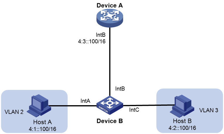
Because Host A's IPv6 address is on the same subnet as Host B's, Host A directly sends an NS message to obtain Host B's MAC address. However, Host B cannot receive the NS message because they are in different VLANs.
To solve this problem, enable local ND proxy on Interface B of the router so that the router can forward messages between Host A and Host B.
Port mirroring
Port mirroring copies the packets passing through a port to the destination port that connects to a data monitoring device for packet analysis. The copies are called mirrored packets.
Port mirroring has the following terms:
· Source port—Monitored port on the device. Packets of the monitored port will be copied and sent to the destination port.
· Source device—Device where a source port resides.
· Destination port—Port that connects to the data monitoring device. Packets of the source port will be copied and sent to the destination port.
· Destination device—Device where the destination port resides.
· Mirroring group—Includes local mirroring group and remote mirroring group.
¡ Local mirroring group—The source port and the destination port are on the same device. A local mirroring group is a mirroring group that contains the source ports and the destination port on the same device.
¡ Remote port mirroring—The source port and the destination port are on different devices. A remote source group is a mirroring group that contains the source ports. A remote destination group is a mirroring group that contains the destination port. In remote port mirroring, mirrored packets are transmitted by the remote probe VLAN from the source device to the destination device.
Static routing
Static routes are manually configured. If a network's topology is simple, you only need to configure static routes for the network to work correctly.
Static routes cannot adapt to network topology changes. If a fault or a topological change occurs in the network, the network administrator must modify the static routes manually.
A default route is used to forward packets that do not match any specific routing entry in the routing table. You can configure a default IPv4 route with destination address 0.0.0.0/0 and configure a default IPv6 route with destination address ::/0.
RIP
Routing Information Protocol (RIP) is a distance-vector IGP suited to small-sized networks. It employs UDP to exchange route information through port 520.
There are two RIP versions, RIPv1 and RIPv2.
· RIPv1 is a classful routing protocol. It advertises messages only through broadcast. RIPv1 messages do not carry mask information, so RIPv1 does not support discontiguous subnets.
· RIPv2 is a classless routing protocol. It supports two transmission modes: broadcast and multicast. Multicast is the default mode using 224.0.0.9 as the multicast address. An interface operating in RIPv2 broadcast mode can also receive RIPv1 messages.
You can enable RIP on a network (in RIP view) or on an interface (in interface view). The configuration in interface view takes precedence over the configuration in RIP view.
RIPv2 supports simple authentication and MD5 authentication (defined in RFC 2082 and RFC 2453) to ensure secure packet exchange.
|
|
NOTE: RIPv1 does not support authentication. |
OSPF
Open Shortest Path First (OSPF) is a link-state IGP that encapsulates its data directly in IP packets using protocol number 89. OSPF applies to networks of various sizes, and it can support hundreds of routers at most.
OSPF supports the MD5/HMAC-MD5 and simple interface authentication modes to prevent route leaking and attacks.
BGP
Border Gateway Protocol (BGP) is an exterior gateway protocol (EGP). It is called internal BGP (IBGP) when it runs within an AS and called external BGP (EBGP) when it runs between ASs. An AS refers to a group of routers that use the same routing policy and work under the same administration.
BGP peer
A router running BGP is a BGP speaker. A BGP speaker establishes peer relationships with other BGP speakers to exchange routing information over TCP connections.
BGP peers include the following types:
· IBGP peers—Reside in the same AS as the local router.
· EBGP peers—Reside in different ASs from the local router.
BGP address families
As shown in Table 18, BGP defines various address families to transmit different routing information.
|
Address family |
Function |
|
BGP IPv4 unicast address family |
Transmits the IPv4 unicast routes in the public network. |
|
BGP IPv4 multicast address family |
PIM uses static and dynamic unicast routes to perform RPF check before creating multicast routing entries. When the multicast and unicast topologies are different, you can use MP-BGP to advertise the routes for RPF check. MP-BGP stores the routes in the BGP multicast routing table. |
|
BGP IPv4 MDT address family |
MP-BGP advertises MDT information including the PE address and default group so that multicast VPN can create a default MDT that uses the PE as the root on the public network. |
|
BGP VPNv4 address family |
Transmits VPNv4 routes. |
|
BGP IPv6 unicast address family |
Transmits the IPv6 unicast routes in the public network. |
|
BGP IPv6 multicast address family |
PIM uses static and dynamic unicast routes to perform RPF check before creating multicast routing entries. When the multicast and unicast topologies are different, you can use MP-BGP to advertise the routes for RPF MP-BGP stores the routes in the BGP multicast routing table. |
|
BGP VPNv6 address family |
Transmits VPNv6 routes. |
|
BGP L2VPN address family |
Transmits L2VPN label block information and remote peer information. |
Redistributing external routes to BGP
BGP peers can exchange routing information. However, BGP does not actively discover routing information. Instead, external routes (for example, IGP routes) are redistributed to the routing table of the specified address family and advertised to the peers.
Policy-based routing
Policy-based routing (PBR) uses user-defined policies to route packets. A policy can specify next hops for packets that match specific criteria such as ACLs.
Policy
A policy includes match criteria and actions to be taken on the matching packets. A policy can have one or multiple nodes as follows:
· Each node is identified by a node number. A smaller node number has a higher priority.
· A node contains the following elements:
¡ Match criterion—Uses an ACL to match packets.
¡ Action—Sets a next hop for the permitted packets. You can associate a next hop with a track entry, and specify whether the next hop is directly connected.
· A node has a match mode of permit or deny.
A policy matches nodes in priority order against packets. If a packet matches the criteria on a node, it is processed by the action on the node. If the packet does not match the criteria on the node, it goes to the next node for a match. If the packet does not match the criteria on any node, it is forwarded according to the routing table.
PBR and Track
PBR can work with the Track feature to dynamically adapt the status of an action to the availability status of a tracked next hop.
· When the track entry changes to Negative, the action is invalid.
· When the track entry changes to Positive or NotReady, the action is valid.
Multicast routing
For other Layer 3 multicast features (such as IGMP and PIM) to take effect, first enable IPv4 multicast routing.
The following tables are involved in IPv4 multicast routing and forwarding:
· IPv4 multicast routing table of each multicast routing protocol, such as the PIM routing table.
· General IPv4 multicast routing table that summarizes multicast routing information generated by different multicast routing protocols.
PIM
Protocol Independent Multicast (PIM) provides IP multicast forwarding by leveraging unicast static routes or unicast routing tables generated by any unicast routing protocol. PIM uses the underlying unicast routing to generate a multicast routing table without relying on any particular unicast routing protocol.
Based on the implementation mechanism, PIM includes the following categories:
· Protocol Independent Multicast–Dense Mode (PIM-DM)—PIM-DM is suitable for small-sized networks with densely distributed multicast members.
· Protocol Independent Multicast–Sparse Mode (PIM-SM)—PIM-SM is suitable for large- and medium-sized networks with sparsely and widely distributed multicast group members.
· Protocol Independent Multicast Source-Specific Multicast (PIM-SSM)—PIM-SSM can be implemented by leveraging part of the PIM-SM technique. Before you configure PIM-SSM, you must first enable PIM-SM.
If you enable PIM-DM on an interface, the PIM-DM mode is used. If you enabled PIM-SM on an interface, the PIM mode on the interface varies by multicast group for which a multicast packet destines.
· If the multicast group is in the SSM group range, the PIM-SSM mode is used.
· If the multicast group is not in the SSM group range, the PIM-SM mode is used.
IGMP
Internet Group Management Protocol (IGMP) establishes and maintains the multicast group memberships between a Layer 3 multicast device and the hosts on the directly connected subnet.
IGMP has the following versions:
· IGMPv1—IGMPv1 manages multicast group memberships based on the query and response mechanism.
· IGMPv2—Backwards-compatible with IGMPv1, IGMPv2 has introduced a querier election mechanism and a leave-group mechanism.
· IGMPv3—Based on and compatible with IGMPv1 and IGMPv2, IGMPv3 enhances the control capabilities of hosts and the query and report capabilities of IGMP routers. IGMPv3 introduced two source filtering modes (Include and Exclude). These modes allow a host to receive or reject multicast data from the specified multicast sources.
After IGMP is enabled on an interface, the interface can establish and maintain multicast group memberships.
IGMP snooping
IGMP snooping runs on a Layer 2 device as a multicast constraining mechanism. It creates Layer 2 multicast forwarding entries from IGMP packets that are exchanged between the hosts and the Layer 3 device.
The Layer 2 device forwards multicast data based on Layer 2 multicast forwarding entries. A Layer 2 multicast forwarding entry contains the VLAN, multicast group address, multicast source address, and host ports. A host port is a multicast receiver-side port on the Layer 2 multicast device.
MLD snooping
MLD snooping runs on a Layer 2 device as an IPv6 multicast constraining mechanism. It creates Layer 2 IPv6 multicast forwarding entries from MLD packets that are exchanged between the hosts and the Layer 3 device.
The Layer 2 device forwards multicast data based on Layer 2 IPv6 multicast forwarding entries. A Layer 2 IPv6 multicast forwarding entry contains the VLAN, IPv6 multicast group address, IPv6 multicast source address, and host ports. A host port is a multicast receiver-side port on the Layer 2 multicast device.
DHCP
The Dynamic Host Configuration Protocol (DHCP) provides a framework to assign configuration information to network devices.
A typical DHCP application scenario has a DHCP server and multiple DHCP clients deployed on the same subnet. DHCP clients can also obtain configuration parameters from a DHCP server on another subnet through a DHCP relay agent.
DHCP server
The DHCP server is well suited to networks where:
· Manual configuration and centralized management are difficult to implement.
· IP addresses are limited. For example, an ISP limits the number of concurrent online users, and users must acquire IP addresses dynamically.
· Most hosts do not need fixed IP addresses.
The DHCP server selects IP addresses and other parameters from an address pool and assigns them to DHCP clients. A DHCP address pool contains the following items:
· Assignable IP addresses.
· Lease duration.
· Gateway addresses.
· Domain name suffix.
· DNS server addresses.
· WINS server addresses.
· NetBIOS node type.
· DHCP options.
Before assigning an IP address, the DHCP server performs IP address conflict detection to verify that the IP address is not in use.
DHCP address pool
The DHCP server supports the following address assignment mechanisms:
· Static address allocation—Manually bind the MAC address or ID of a client to an IP address in a DHCP address pool. When the client requests an IP address, the DHCP server assigns the IP address in the static binding to the client.
· Dynamic address allocation—Specify IP address ranges in a DHCP address pool. Upon receiving a DHCP request, the DHCP server dynamically selects an IP address from the matching IP address range in the address pool.
You can specify the lease duration for IP addresses in the DHCP address pool.
The DHCP server observes the following principles to select an address pool for a client:
· If there is an address pool where an IP address is statically bound to the MAC address or ID of the client, the DHCP server selects this address pool and assigns the statically bound IP address and other configuration parameters to the client.
· If no static address pool is configured, the DHCP server selects an address pool depending on the client location.
¡ Client on the same subnet as the server—The DHCP server compares the IP address of the receiving interface with the subnets of all address pools. If a match is found, the server selects the address pool with the longest-matching subnet.
¡ Client on a different subnet than the server—The DHCP server compares the IP address in the giaddr field of the DHCP request with the subnets of all address pools. If a match is found, the server selects the address pool with the longest-matching subnet.
IP address allocation sequence
The DHCP server selects an IP address for a client in the following sequence:
1. IP address statically bound to the client's MAC address or ID.
2. IP address that was ever assigned to the client.
3. IP address designated by the Option 50 field in the DHCP-DISCOVER message sent by the client. Option 50 is the Requested IP Address option. The client uses this option to specify the wanted IP address in a DHCP-DISCOVER message. The content of Option 50 is user defined.
4. First assignable IP address found in the way of selecting an address pool.
5. IP address that was a conflict or passed its lease duration. If no IP address is assignable, the server does not respond.
DHCP options
DHCP uses the options field to carry information for dynamic address allocation and provide additional configuration information for clients.
You can customize options for the following purposes:
· Add newly released DHCP options.
· Add options for which the vendor defines the contents, for example, Option 43. DHCP servers and clients can use vendor-specific options to exchange vendor-specific configuration information.
· Add options for which the Web interface does not provide a dedicated configuration page. For example, you can use Option 4 to specify the time server address 1.1.1.1 for DHCP clients.
· Add all option values if the actual requirement exceeds the limit for a dedicated option configuration page. For example, on the DNS server configuration page, you can specify up to eight DNS servers. To specify more than eight DNS servers, you can use Option 6 to specify all DNS servers.
The following table shows the most commonly used DHCP options.
|
Option number |
Option name |
Recommended padding format |
|
3 |
Router |
IP address |
|
6 |
Domain Name Server |
IP address |
|
15 |
Domain Name |
ASCII string |
|
44 |
NetBIOS over TCP/IP Name Server |
IP address |
|
46 |
NetBIOS over TCP/IP Node Type |
Hexadecimal string |
|
66 |
TFTP server name |
ASCII string |
|
67 |
Bootfile name |
ASCII string |
|
43 |
Vendor Specific Information |
Hexadecimal string |
IP address conflict detection
Before assigning an IP address, the DHCP server pings the IP address.
· If the server receives a response within the specified period, it selects and pings another IP address.
· If it receives no response, the server continues to ping the IP address until a specific number of ping packets are sent. If still no response is received, the server assigns the IP address to the requesting client.
DHCP relay agent
The DHCP relay agent enables clients to get IP addresses from a DHCP server on another subnet. This feature avoids deploying a DHCP server for each subnet to centralize management and reduce investment.
DHCP relay entry recording
This function enables the DHCP relay agent to automatically record clients' IP-to-MAC bindings (relay entries) after they obtain IP addresses through DHCP.
Some security functions use the relay entries to check incoming packets and block packets that do not match any entry. In this way, illegal hosts are not able to access external networks through the relay agent. Examples of the security functions are ARP address check, authorized ARP, and IP source guard.
Periodic refreshing of dynamic DHCP relay entries
A DHCP client unicasts a DHCP-RELEASE message to the DHCP server to release its IP address. The DHCP relay agent conveys the message to the DHCP server and does not remove the IP-to-MAC entry of the client.
With this feature, the DHCP relay agent uses the following information to periodically send a DHCP-REQUEST message to the DHCP server:
· The IP address of a relay entry.
· The MAC address of the DHCP relay interface.
The relay agent maintains the relay entries depending on what it receives from the DHCP server:
· If the server returns a DHCP-ACK message or does not return any message within an interval, the DHCP relay agent removes the relay entry. In addition, upon receiving the DHCP-ACK message, the relay agent sends a DHCP-RELEASE message to release the IP address.
· If the server returns a DHCP-NAK message, the relay agent keeps the relay entry.
HTTP/HTTPS
The device provides a built-in Web server. After you enable the Web server on the device, users can log in to the Web interface to manage and monitor the device.
The device's built-in Web server supports both Hypertext Transfer Protocol (HTTP) (version 1) and Hypertext Transfer Protocol Secure (HTTPS). HTTPS is more secure than HTTP because of the following items:
· HTTPS uses SSL to ensure the integrity and security of data exchanged between the client and the server.
· HTTPS allows you to define a certificate attribute-based access control policy to allow only legal clients to access the Web interface.
You can also specify a basic ACL for HTTP or HTTPS to prevent unauthorized Web access.
· If you does not specify an ACL for HTTP or HTTPS, or the specified ACL does not exist or does not have rules, the device permits all HTTP or HTTPS logins.
· If the specifies ACL has rules, only users permitted by the ACL can log in to the Web interface through HTTP or HTTPS.
SSH
Secure Shell (SSH) is a network security protocol. Using encryption and authentication, SSH can implement secure remote access and file transfer over an insecure network.
SSH uses the typical client-server model to establish a channel for secure data transfer based on TCP.
SSH includes two versions: SSH1.x and SSH2.0 (hereinafter referred to as SSH1 and SSH2), which are not compatible. SSH2 is better than SSH1 in performance and security.
The device can act as an SSH server to provide the following SSH applications to SSH clients:
· Secure Telnet—Stelnet provides secure and reliable network terminal access services. Through Stelnet, a user can securely log in to a remote server. Stelnet can protect devices against attacks, such as IP spoofing and plain text password interception. The device can act as an Stelnet server or an Stelnet client.
· Secure File Transfer Protocol—Based on SSH2, SFTP uses SSH connections to provide secure file transfer.
· Secure Copy—Based on SSH2, SCP offers a secure method to copy files.
· When acting as an Stelnet, SFTP, or SCP server, the device supports both SSH2 and SSH1 in non-FIPS mode and only SSH2 in FIPS mode.
FTP
File Transfer Protocol (FTP) is an application layer protocol for transferring files from one host to another over an IP network. It uses TCP port 20 to transfer data and TCP port 21 to transfer control commands.
The device can act as the FTP server.
Telnet
The device can act as a Telnet server to allow Telnet login. After you configure Telnet service on the device, users can remotely log in to the device to manage and monitor the device.
To prevent unauthorized Telnet logins, you can use ACLs to filter Telnet logins.
· If you does not specify an ACL for Telnet service, or the specified ACL does not exist or does not have rules, the device permits all Telnet logins.
· If the specified ACL has rules, only users permitted by the ACL can Telnet to the device.
NTP
Synchronize your device with a trusted time source by using the Network Time Protocol (NTP) or changing the system time before you run it on a live network.
NTP uses stratum to define the accuracy of each server. The value is in the range of 1 to 15. A smaller value represents a higher accuracy.
If the devices in a network cannot synchronize to an authoritative time source, you can perform the following tasks:
· Select a device that has a relatively accurate clock from the network.
· Use the local clock of the device as the reference clock to synchronize other devices in the network.
You can configure the local clock as a reference clock in the Web interface.
SNMP
Simple Network Management Protocol (SNMP) is an Internet standard protocol widely used for a network management station (NMS) to access and manage the devices (agents) on a network. After you enable SNMP on the device, the device acts as an SNMP agent.
SNMP enables an NMS to read and set the values of the variables on an agent. The agent sends traps to report events to the NMS.
MIB
Management Information Base (MIB) is a collection of objects. It defines hierarchical relations between objects and object properties, including object name, access privilege, and data type.
An NMS manages a device by reading and setting the values of variables (for example, interface status and CPU usage) on the device. These variables are objects in the MIB.
OID and subtree
A MIB stores variables called "nodes" or "objects" in a tree hierarchy and identifies each node with a unique OID. An OID is a dotted numeric string that uniquely identifies the path from the root node to a leaf node. For example, the object internet is uniquely identified by the OID {1.3.6.1}.
A subtree is like a branch in the tree hierarchy. It contains a root node and the lower-level nodes of the root node. A subtree is identified by the OID of the root node.
MIB view
A MIB view is a subset of a MIB. You can control NMS access to MIB objects by specifying a MIB view for the username or community name that the NMS uses. For a subtree included in a MIB view, all nodes in the subtree are accessible to the NMS. For a subtree excluded in a MIB view, all nodes in the subtree are inaccessible to the NMS.
Subtree mask
A subtree mask is in hexadecimal format. It identifies a MIB view collectively with the subtree OID.
To determine whether an MIB object is in a MIB view, convert the subnet mask to binary bits (0 and 1) and match each bit with each node number of the object OID from left to right. If the 1-bit corresponded node numbers of the object OID are the same as those of the subtree OID, the MIB object is in the MIB view. The 0-bit corresponded node numbers can be different from those of the subtree OID.
For example, the view determined by the subtree OID 1.3.6.1.6.1.2.1 and the subtree mask 0xDB (11011011 in binary) includes all the nodes under the subtree OID 1.3.*.1.6.*.2.1, where * represents any number.
|
|
NOTE: · If the number of bits in the subtree mask is greater than the number of nodes of the OID, the excessive bits of the subtree mask will be ignored during subtree mask-OID matching. · If the number of bits in the subtree mask is smaller than the number of nodes of the OID, the short bits of the subtree mask will be set to 1 during subtree mask-OID matching. · If no subtree mask is specified, the default subtree mask (all ones) will be used for mask-OID matching. |
SNMP versions
You can enable SNMPv1, SNMPv2c, or SNMPv3 on a device. For an NMS and an agent to communicate, they must run the same SNMP version.
· SNMPv1 and SNMPv2c use community name for authentication. An NMS can access a device only when the NMS and the device use the same community name.
· SNMPv3 uses username for authentication and allows you to configure an authentication key and a privacy key to enhance communication security. The authentication key authenticates the validity of the packet sender. The privacy key is used to encrypt the packets transmitted between the NMS and the device.
SNMP access control
SNMPv1 and SNMPv2 access control
SNMPv1 and SNMPv2 uses community name for authentication. To control NMS access to MIB objects, configure one or both of the following settings on the community name that the NMS uses:
· Specify a MIB view for the community. You can specify only one MIB view for a community.
¡ If you grant read-only permission to the community, the NMS can only read the values of the objects in the MIB view.
¡ If you grant read-write permission to the community, the NMS can read and set the values of the objects in the MIB view.
· Specify a basic IPv4 ACL or a basic IPv6 ACL for the community to filter illegitimate NMSs from accessing the agent.
¡ Only NMSs with the IPv4/IPv6 address permitted in the IPv4/IPv6 ACL can access the SNMP agent.
¡ If you do not specify an ACL, or the specified ACL does not exist, all NMSs in the SNMP community can access the SNMP agent. If the specified ACL does not have any rules, no NMS in the SNMP community can access the SNMP agent.
SNMPv3 access control
SNMPv3 uses username for authentication. To control NMS access to MIB objects, configure one or both of the following settings on the username that the NMS uses:
· Create an SNMPv3 group and assign the username to the group. The user has the same access right as the group.
When you create the group, specify one or more MIB views for the group. The MIB views include read-only MIB view, read-write MIB view, or notify MIB view. You can specify only one MIB view of a type for a group.
¡ Read-only MIB view only allows the group to read the values of the objects in the view.
¡ Read-write MIB view allows the group to read and set the values of the object in the view.
¡ Notify MIB view automatically sends a notification to the NMS when the group accesses the view.
· Specify a basic IPv4 ACL or a basic IPv6 ACL for both the user and group to filter illegitimate NMSs from accessing the agent.
¡ Only the NMSs permitted by ACLs specified for both the user and group can access the agent.
¡ If you do not specify an ACL, or the specified ACL does not exist, all NMSs in the SNMP community can access the SNMP agent. If the specified ACL does not have any rules, no NMS in the SNMP community can access the SNMP agent.
Resources features
Resource features are common resources that can be used by multiple features. For example, you can use an ACL both in a packet filter to filter traffic and in a QoS policy to match traffic.
The Web interface provides access to the resource creation page for features that might use the resources. When you configure these features, you can create a resource without having to navigate to the Resources menu. However, to modify or remove a resource, you must access the Resources menu.
ACL
An access control list (ACL) is a set of rules (or permit or deny statements) for identifying traffic based on criteria such as source IP address, destination IP address, and port number.
ACLs are primarily used for packet filtering. You can use ACLs in QoS, security, routing, and other feature modules for identifying traffic. The packet drop or forwarding decisions depend on the modules that use ACLs.
ACL types and match criteria
Table 19 shows the ACL types available on the switch and the fields that can be used to filter or match traffic.
Table 19 ACL types and match criteria
|
Type |
ACL number |
IP version |
Match criteria |
|
Basic ACLs |
2000 to 2999 |
IPv4 |
Source IPv4 address. |
|
IPv6 |
Source IPv6 address. |
||
|
Advanced ACLs |
3000 to 3999 |
IPv4 |
· Source IPv4 address. · Destination IPv4 address. · Packet priority. · Protocol number. · Other Layer 3 and Layer 4 header fields. |
|
IPv6 |
· Source IPv6 address. · Destination IPv6 address. · Packet priority. · Protocol number. · Other Layer 3 and Layer 4 header fields. |
||
|
Ethernet frame header ACLs |
4000 to 4999 |
IPv4 and IPv6 |
Layer 2 header fields, including: · Source and destination MAC addresses. · 802.1p priority. · Link layer protocol type. |
Match order
The rules in an ACL are sorted in a specific order. When a packet matches a rule, the device stops the match process and performs the action defined in the rule. If an ACL contains overlapping or conflicting rules, the matching result and action to take depend on the rule order.
The following ACL match orders are available:
· config—Sorts ACL rules in ascending order of rule ID. A rule with a lower ID is matched before a rule with a higher ID. If you use this method, check the rules and their order carefully.
|
|
NOTE: The match order of user-defined ACLs can only be config. |
· auto—Sorts ACL rules in depth-first order. Depth-first ordering makes sure any subset of a rule is always matched before the rule. Table 20 lists the sequence of tie breakers that depth-first ordering uses to sort rules for each type of ACL.
Table 20 Sort ACL rules in depth-first order
|
ACL category |
Sequence of tie breakers |
|
IPv4 basic ACL |
1. VPN instance. 2. More 0s in the source IPv4 address wildcard (more 0s means a narrower IPv4 address range). 3. Rule configured earlier. |
|
IPv4 advanced ACL |
1. VPN instance. 2. Specific protocol number. 3. More 0s in the source IPv4 address wildcard mask. 4. More 0s in the destination IPv4 address wildcard. 5. Narrower TCP/UDP service port number range. 6. Rule configured earlier. |
|
IPv6 basic ACL |
1. VPN instance. 2. Longer prefix for the source IPv6 address (a longer prefix means a narrower IPv6 address range). 3. Rule configured earlier. |
|
IPv6 advanced ACL |
1. VPN instance. 2. Specific protocol number. 3. Longer prefix for the source IPv6 address. 4. Longer prefix for the destination IPv6 address. 5. Narrower TCP/UDP service port number range. 6. Rule configured earlier. |
|
Ethernet frame header ACL |
1. More 1s in the source MAC address mask (more 1s means a smaller MAC address). 2. More 1s in the destination MAC address mask. 3. Rule configured earlier. |
|
|
NOTE: A wildcard mask, also called an inverse mask, is a 32-bit binary number represented in dotted decimal notation. In contrast to a network mask, the 0 bits in a wildcard mask represent "do care" bits, and the 1 bits represent "don't care" bits. If the "do care" bits in an IP address are identical to the "do care" bits in an IP address criterion, the IP address matches the criterion. All "don't care" bits are ignored. The 0s and 1s in a wildcard mask can be noncontiguous. For example, 0.255.0.255 is a valid wildcard mask. |
Rule numbering
ACL rules can be manually numbered or automatically numbered.
Rule numbering step
If you do not assign an ID to the rule you are creating, the system automatically assigns it a rule ID. The rule numbering step sets the increment by which the system automatically numbers rules. For example, the default ACL rule numbering step is 5. If you do not assign IDs to rules you are creating, they are automatically numbered 0, 5, 10, 15, and so on. The wider the numbering step, the more rules you can insert between two rules.
By introducing a gap between rules rather than contiguously numbering rules, you have the flexibility of inserting rules in an ACL. This feature is important for a config-order ACL, where ACL rules are matched in ascending order of rule ID.
Automatic rule numbering and renumbering
The ID automatically assigned to an ACL rule takes the nearest higher multiple of the numbering step to the current highest rule ID, starting with 0.
For example, if the numbering step is 5 (the default), and there are five ACL rules numbered 0, 5, 9, 10, and 12, the newly defined rule is numbered 15. If the ACL does not contain any rule, the first rule is numbered 0.
Whenever the step changes, the rules are renumbered, starting from 0. For example, if there are five rules numbered 5, 10, 13, 15, and 20, changing the step from 5 to 2 causes the rules to be renumbered 0, 2, 4, 6, and 8.
Time range
You can implement a service based on the time of the day by applying a time range to it. A time-based service only takes effect in any time periods specified by the time range. For example, you can implement time-based ACL rules by applying a time range to them. If a time range does not exist, the service based on the time range does not take effect.
The following basic types of time ranges are available:
· Periodic time range—Recurs periodically on a day or days of the week.
· Absolute time range—Represents only a period of time and does not recur.
A time range is uniquely identified by the time range name. A time range can include multiple periodic statements and absolute statements. The active period of a time range is calculated as follows:
1. Combining all periodic statements.
2. Combining all absolute statements.
3. Taking the intersection of the two statement sets as the active period of the time range.
QoS features
QoS policies
In data communications, Quality of Service (QoS) provides differentiated service guarantees for diversified traffic in terms of bandwidth, delay, jitter, and drop rate, all of which can affect QoS.
By associating a traffic behavior with a traffic class in a QoS policy, you apply QoS actions in the traffic behavior to the traffic class.
Traffic class
A traffic class defines a set of match criteria for classifying traffic.
Traffic behavior
A traffic behavior defines a set of QoS actions to take on packets.
QoS policy
A QoS policy associates traffic classes with traffic behaviors and performs the actions in each behavior on its associated traffic class.
Applying a QoS policy
You can apply a QoS policy to the following destinations:
· Interface—The QoS policy takes effect on the traffic sent or received on the interface. The QoS policy applied to the outgoing traffic on an interface or PVC does not regulate local packets. Local packets refer to critical protocol packets sent by the local system for operation maintenance. The most common local packets include link maintenance, LDP, and SSH packets.
· VLAN—The QoS policy takes effect on the traffic sent or received on all ports in the VLAN.
· Globally—The QoS policy takes effect on the traffic sent or received on all ports.
Hardware queuing
Congestion occurs on a link or node when the traffic size exceeds the processing capability of the link or node. Congestion is unavoidable in switched networks or multiuser application environments. To improve the service performance of your network, implement congestion management policies. Queuing is a common congestion management technique. SP, WRR, and WFQ are common queuing methods.
SP queuing
Figure 8 SP queuing
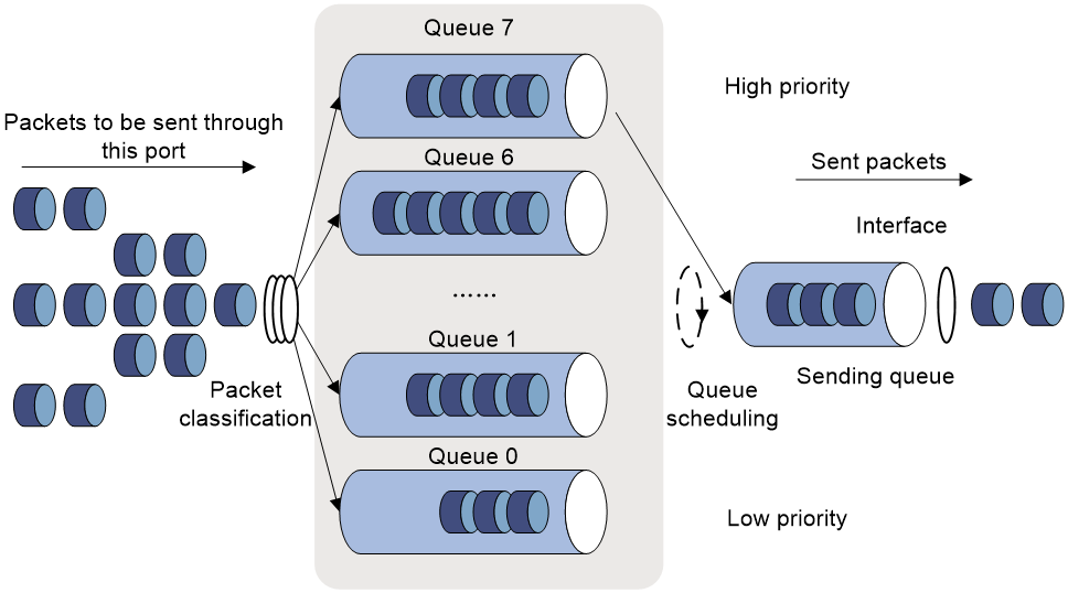
SP queuing is designed for mission-critical applications that require preferential service to reduce the response delay when congestion occurs. SP queuing classifies eight queues on a port into eight classes, numbered 7 to 0 in descending priority order.
SP queuing schedules the eight queues in the descending order of priority. SP queuing sends packets in the queue with the highest priority first. When the queue with the highest priority is empty, it sends packets in the queue with the second highest priority, and so on. You can assign mission-critical packets to a high priority queue to make sure they are always serviced first. Common service packets can be assigned to low priority queues to be transmitted when high priority queues are empty.
The disadvantage of SP queuing is that packets in the lower priority queues cannot be transmitted if packets exist in the higher priority queues. In the worst case, lower priority traffic might never get serviced.
WRR queuing
Figure 9 WRR queuing

WRR queuing schedules all the queues in turn to ensure every queue is serviced for some time. Assume that a port provides eight output queues. WRR assigns each queue a weight value (represented by w7, w6, w5, w4, w3, w2, w1, or w0). The weight value of a queue decides the proportion of resources assigned to the queue. On a 100 Mbps port, you can set the weight values to 50, 30, 10, 10, 50, 30, 10, and 10 for w7 through w0. In this way, the queue with the lowest priority can get a minimum of 5 Mbps bandwidth. WRR solves the problem that SP queuing might fail to service packets in low-priority queues for a long time.
Another advantage of WRR queuing is that when the queues are scheduled in turn, the service time for each queue is not fixed. If a queue is empty, the next queue will be scheduled immediately. This improves bandwidth resource use efficiency.
WRR queuing includes the following types:
· Basic WRR queuing—Contains multiple queues. You can configure the weight for each queue, and WRR schedules these queues based on the user-defined parameters in a round robin manner.
· Group-based WRR queuing—All the queues are scheduled by WRR. You can divide output queues to WRR group 1 and WRR group 2. Round robin queue scheduling is performed for group 1 first. When group 1 is empty, round robin queue scheduling is performed for group 2.
On an interface enabled with group-based WRR queuing, you can assign queues to the SP group. Queues in the SP group are scheduled with SP. The SP group has higher scheduling priority than the WRR groups.
WRR group 1 is supported in the current software version.
WFQ queuing
Figure 10 WFQ queuing
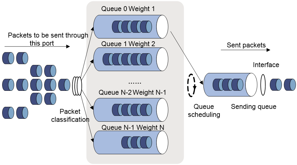
WFQ can automatically classify traffic according to the "session" information of traffic (protocol type, TCP or UDP source/destination port numbers, source/destination IP addresses, IP precedence bits in the ToS field, and so on). WFQ provides as many queues as possible so that each traffic flow can be put into a different queue to balance the delay of every traffic flow on a whole. When dequeuing packets, WFQ assigns the outgoing interface bandwidth to each traffic flow by precedence. The higher precedence value a traffic flow has, the more bandwidth it gets.
Assume that five flows exist in the current interface with precedence 0, 1, 2, 3, and 4. The total bandwidth quota is the sum of all the (precedence value + 1), namely, 1 + 2 + 3 + 4 + 5 = 15. The bandwidth percentage assigned to each flow is (precedence value of the flow + 1)/total bandwidth quota. The bandwidth percentages for the flows are 1/15, 2/15, 3/15, 4/15, and 5/15.
WFQ is similar to WRR. On an interface with group-based WFQ queuing enabled, you can assign queues to the SP group. Queues in the SP group are scheduled with SP. The SP group has higher scheduling priority than the WFQ groups. The difference is that WFQ enables you to set guaranteed bandwidth that a WFQ queue can get during congestion.
WFQ queue configuration from the Web interface is not supported in the current software version.
Queue scheduling profile
Queue scheduling profiles support two queue scheduling algorithms: SP and WRR. In a queue scheduling profile, you can configure SP + WRR. When the two queue scheduling algorithms are configured, SP queues and WRR groups are scheduled in descending order of queue ID. In a WRR group, queues are scheduled based on their weights. When SP and WRR groups are configured in a queue scheduling profile, the following figure shows the scheduling order.
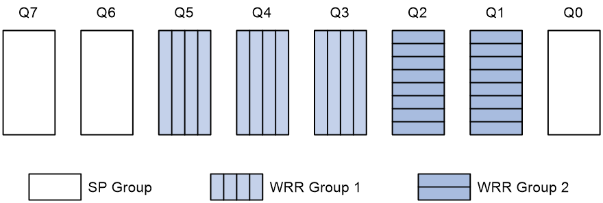
· Queue 7 has the highest priority. Its packets are sent preferentially.
· Queue 6 has the second highest priority. Packets in queue 6 are sent when queue 7 is empty.
· Queue 3, queue 4, and queue 5 are scheduled according to their weights. When both queue 6 and queue 7 are empty, WRR group 1 is scheduled.
· Queue 1 and queue 2 are scheduled according to their weights. WRR group 2 is scheduled when queue 7, queue 6, queue 5, queue 4, and queue 3 are all empty.
· Queue 0 has the lowest priority, and it is scheduled when all other queues are empty.
Priority mapping
When a packet arrives, a device assigns values of priority parameters to the packet for the purpose of queue scheduling and congestion control.
Priority mapping allows you to modify the priority values of the packet according to priority mapping rules. The priority parameters decide the scheduling priority and forwarding priority of the packet.
Port priority
When a port is configured with a priority trust mode, the device trusts the priorities included in incoming packets. The device can automatically resolves the priorities or flag bits included in packets. The device then maps the trusted priority to the target priority types and values according to the priority maps.
When a port is not configured with a priority trust mode and is configured with a port priority, the device does not trust the priorities included in incoming packets. The device uses its port priority to look for priority parameters for the incoming packets.
Configuring the port priority
After you configure a port priority for a port, the device uses its port priority to look for priority parameters for the incoming packets.
Configuring the priority trust mode
After you configure a priority trust mode for a port, the device maps the trusted priority in incoming packets to the target priority types and values according to the priority maps.
The available priority trust modes include the following types:
· Untrust—Does not trust any priority included in packets.
· Dot1p—Trusts the 802.1p priorities included in packets.
· DSCP—Trusts the DSCP priorities included in IP packets.
Priority map
The device provides three priority maps: 802.1p-lp, DSCP-802.1p, and DSCP-DSCP. If a default priority map cannot meet your requirements, you can modify the priority map as required.
Rate limit
Rate limit uses token buckets for traffic control. If there are tokens in the token bucket, bursty traffic is allowed. Otherwise, packets are not forwarded until new tokens are generated. In this way, packets are limited to the token generation rate while bursty traffic is allowed.
A token bucket has the following configurable parameters:
· Mean rate at which tokens are put into the bucket, which is the permitted average rate of traffic. It is usually set to the committed information rate (CIR).
· Burst size or the capacity of the token bucket. It is the maximum traffic size permitted in each burst. It is usually set to the committed burst size (CBS). The set burst size must be greater than the maximum packet size.
Each arriving packet is evaluated. In each evaluation, if the number of tokens in the bucket is enough, the traffic conforms to the specification and the tokens for forwarding the packet are taken away. If the number of tokens in the bucket is not enough, the traffic is excessive.
When rate limit is configured on an interface, a token bucket handles all packets to be sent through the interface for rate limiting. If enough tokens are in the token bucket, packets can be forwarded. Otherwise, packets are put into QoS queues for congestion management. In this way, the traffic passing the interface is controlled.
Security features
Packet filter
Packet filter uses ACLs to filter incoming or outgoing packets on interfaces, VLANs, or globally. An interface permits packets that match permit statements to pass through, and denies packets that match deny statements. The default action applies to packets that do not match any ACL rules.
IP source guard
Overview
IP source guard (IPSG) prevents spoofing attacks by using an IPSG binding table to match legitimate packets. It drops all packets that do not match the table.
The IPSG binding table can include the following bindings:
· IP-interface.
· MAC-interface.
· IP-MAC-interface.
· IP-VLAN-interface.
· MAC-VLAN-interface.
· IP-MAC-VLAN-interface.
Interface-specific static IPv4SG bindings
Interface-specific static IPv4SG bindings are configured manually and take effect only on the interface. They are suitable for scenarios where a few hosts exist on a LAN and their IP addresses are manually configured. For example, you can configure a static IPv4SG binding on an interface that connects to a server. This binding allows the interface to receive packets only from the server.
Static IPv4SG bindings on an interface implements the following functions:
· Filter incoming IPv4 packets on the interface.
· Cooperate with ARP detection for user validity checking.
You can configure the same static IPv4SG binding on different interfaces.
802.1X
802.1X is a port-based network access control protocol that controls network access by authenticating the devices connected to 802.1X-enabled LAN ports.
802.1X architecture
802.1X includes the following entities:
· Client—A user terminal seeking access to the LAN. The terminal must have 802.1X software to authenticate to the access device.
· Access device—Authenticates the client to control access to the LAN. In a typical 802.1X environment, the access device uses an authentication server to perform authentication.
· Authentication server—Provides authentication services for the access device. The authentication server first authenticates 802.1X clients by using the data sent from the access device. Then, the server returns the authentication results to the access device to make access decisions. The authentication server is typically a RADIUS server. In a small LAN, you can use the access device as the authentication server.
802.1X authentication methods
The access device can perform EAP relay or EAP termination to communicate with the RADIUS server.
· EAP termination—The access device performs the following operations in EAP termination mode:
a. Terminates the EAP packets received from the client.
b. Encapsulates the client authentication information in standard RADIUS packets.
c. Uses PAP or CHAP to authenticate to the RADIUS server.
CHAP does not send plaintext password to the RADIUS server, and PAP sends plaintext password to the RADIUS server.
· EAP relay—The access device uses EAPOR packets to send authentication information to the RADIUS server.
Access control methods
Comware implements port-based access control as defined in the 802.1X protocol, and extends the protocol to support MAC-based access control.
· Port-based access control—Once an 802.1X user passes authentication on a port, all subsequent users can access the network through the port without authentication. When the authenticated user logs off, all other users are logged off.
· MAC-based access control—Each user is separately authenticated on a port. When a user logs off, no other online users are affected.
Port authorization state
The port authorization state determines whether the client is granted access to the network. You can control the authorization state of a port by using the following options:
· Authorized—Places the port in the authorized state, enabling users on the port to access the network without authentication.
· Unauthorized—Places the port in the unauthorized state, denying any access requests from users on the port.
· Auto—Places the port initially in unauthorized state to allow only EAPOL packets to pass. After a user passes authentication, sets the port in the authorized state to allow access to the network. You can use this option in most scenarios.
Periodic online user reauthentication
Periodic online user reauthentication tracks the connection status of online users, and updates the authorization attributes assigned by the server. The attributes include the ACL, VLAN, and user profile-based QoS. The reauthentication interval is user configurable.
Online user handshake
The online user handshake feature checks the connectivity status of online 802.1X users. The access device sends handshake messages to online users at the handshake interval. If the device does not receive any responses from an online user after it has made the maximum handshake attempts, the device sets the user to offline state.
You can also enable the online user handshake security feature to check authentication information in the handshake packets from clients. With this feature, the device prevents 802.1X users who use illegal client software from bypassing iNode security check such as dual network interface cards (NICs) detection.
Authentication trigger
The access device initiates authentication, if a client cannot send EAPOL-Start packets. One example is the 802.1X client available with Windows XP.
The access device supports the following modes:
· Unicast trigger mode—Upon receiving a frame from an unknown MAC address, the access device sends an Identity EAP-Request packet out of the receiving port to the MAC address. The device retransmits the packet if no response has been received within the specified interval.
· Multicast trigger mode—The access device multicasts Identity EAP-Request packets periodically (every 30 seconds by default) to initiate 802.1X authentication.
Auth-Fail VLAN
The 802.1X Auth-Fail VLAN on a port accommodates users who have failed 802.1X authentication because of the failure to comply with the organization security strategy. For example, the VLAN accommodates users who have entered a wrong password. The Auth-Fail VLAN does not accommodate 802.1X users who have failed authentication for authentication timeouts or network connection problems.
The access device handles VLANs on an 802.1X-enabled port based on its 802.1X access control method.
· On a port that performs port-based access control:
|
Authentication status |
VLAN manipulation |
|
A user fails 802.1X authentication. |
The device assigns the Auth-Fail VLAN to the port as the PVID. All 802.1X users on this port can access only resources in the Auth-Fail VLAN. |
|
A user in the 802.1X Auth-Fail VLAN fails 802.1X reauthentication |
The Auth-Fail VLAN is still the PVID on the port, and all 802.1X users on this port are in this VLAN. |
|
A user passes 802.1X authentication. |
· The device assigns the authorization VLAN of the user to the port as the PVID, and it removes the port from the Auth-Fail VLAN. After the user logs off, the guest VLAN is assigned to the port as the PVID. If no guest VLAN is configured, the initial PVID of the port is restored. · If the authentication server does not authorize a VLAN, the initial PVID of the port applies. The user and all subsequent 802.1X users are assigned to the initial PVID. After the user logs off, the PVID remains unchanged. |
· On a port that performs MAC-based access control:
|
Authentication status |
VLAN manipulation |
|
A user fails 802.1X authentication. |
The device maps the MAC address of the user to the 802.1X Auth-Fail VLAN. The user can access only resources in the Auth-Fail VLAN. |
|
A user in the 802.1X Auth-Fail VLAN fails 802.1X reauthentication. |
The user is still in the Auth-Fail VLAN. |
|
A user in the 802.1X Auth-Fail VLAN passes 802.1X authentication. |
The device remaps the MAC address of the user to the authorization VLAN. If the authentication server does not authorize a VLAN, the device remaps the MAC address of the user to the initial PVID on the port. |
Guest VLAN
The 802.1X guest VLAN on a port accommodates users who have not performed 802.1X authentication. Once a user in the guest VLAN passes 802.1X authentication, it is removed from the guest VLAN and can access authorized network resources.
The access device handles VLANs on an 802.1X-enabled port based on its 802.1X access control method.
· On a port that performs port-based access control:
|
Authentication status |
VLAN manipulation |
|
A user has not passed 802.1X authentication. |
The device assigns the 802.1X guest VLAN to the port as the PVID. All 802.1X users on this port can access only resources in the guest VLAN. If no 802.1X guest VLAN is configured, the access device does not perform any VLAN operation. |
|
A user in the 802.1X guest VLAN fails 802.1X authentication. |
If an 802.1X Auth-Fail VLAN (see "Auth-Fail VLAN") is available, the device assigns the Auth-Fail VLAN to the port as the PVID. All users on this port can access only resources in the Auth-Fail VLAN. If no Auth-Fail VLAN is configured, the PVID on the port is still the 802.1X guest VLAN. All users on the port are in the guest VLAN. |
|
A user in the 802.1X guest VLAN passes 802.1X authentication. |
· The device assigns the authorization VLAN of the user to the port as the PVID, and it removes the port from the 802.1X guest VLAN. After the user logs off, the initial PVID of the port is restored. · If the authentication server does not authorize a VLAN, the initial PVID applies. The user and all subsequent 802.1X users are assigned to the initial port VLAN. After the user logs off, the port VLAN remains unchanged. NOTE: The initial PVID of an 802.1X-enabled port refers to the PVID used by the port before the port is assigned to any 802.1X VLANs. |
· On a port that performs MAC-based access control:
|
Authentication status |
VLAN manipulation |
|
A user has not passed 802.1X authentication and is in the authentication process. |
The device creates a mapping between the MAC address of the user and the 802.1X guest VLAN. The user can access only resources in the guest VLAN. |
|
A user in the 802.1X guest VLAN fails 802.1X authentication. |
If an 802.1X Auth-Fail VLAN is available, the device remaps the MAC address of the user to the Auth-Fail VLAN. The user can access only resources in the Auth-Fail VLAN. If no 802.1X Auth-Fail VLAN is configured, the user is still in the 802.1X guest VLAN. |
|
A user in the 802.1X guest VLAN passes 802.1X authentication. |
The device remaps the MAC address of the user to the authorization VLAN. If the authentication server does not authorize a VLAN, the device remaps the MAC address of the user to the initial PVID on the port. |
Critical VLAN
The 802.1X critical VLAN on a port accommodates 802.1X users who have failed authentication because none of the RADIUS servers in their ISP domain is reachable. The critical VLAN feature takes effect when 802.1X authentication is performed only through RADIUS servers. If an 802.1X user fails local authentication after RADIUS authentication, the user is not assigned to the critical VLAN.
The access device handles VLANs on an 802.1X-enabled port based on its 802.1X access control method.
· On a port that performs port-based access control:
|
Authentication status |
VLAN manipulation |
|
A user that has not been assigned to any VLAN fails 802.1X authentication because all the RADIUS servers are unreachable. |
The device assigns the critical VLAN to the port as the PVID. The 802.1X user and all subsequent 802.1X users on this port can access only resources in the 802.1X critical VLAN. |
|
A user in the 802.1X critical VLAN fails authentication because all the RADIUS servers are unreachable. |
The critical VLAN is still the PVID of the port, and all 802.1X users on this port are in this VLAN. |
|
A user in the 802.1X critical VLAN fails authentication for any other reasons except for unreachable servers. |
If an 802.1X Auth-Fail VLAN has been configured, the PVID of the port changes to the Auth-Fail VLAN ID, and all 802.1X users on this port are moved to the Auth-Fail VLAN. If no 802.1X Auth-Fail VLAN is configured, the initial PVID of the port is restored. |
|
A user in the 802.1X critical VLAN passes 802.1X authentication. |
· The device assigns the authorization VLAN of the user to the port as the PVID, and it removes the port from the 802.1X critical VLAN. After the user logs off, the guest VLAN ID changes to the PVID. If no 802.1X guest VLAN is configured, the initial PVID of the port is restored. · If the authentication server (either the local access device or a RADIUS server) does not authorize a VLAN, the initial PVID of the port applies. The user and all subsequent 802.1X users are assigned to this port VLAN. After the user logs off, the PVID remains unchanged. |
|
A user in the 802.1X guest VLAN fails authentication because all the RADIUS servers are unreachable. |
The device assigns the 802.1X critical VLAN to the port as the PVID, and all 802.1X users on this port are in this VLAN. |
|
A user in the 802.1X Auth-Fail VLAN fails authentication because all the RADIUS servers are unreachable. |
The PVID of the port remains unchanged. All 802.1X users on this port can access only resources in the 802.1X Auth-Fail VLAN. |
|
A user who has passed authentication fails reauthentication because all the RADIUS servers are unreachable, and the user is logged out of the device. |
The device assigns the 802.1X critical VLAN to the port as the PVID. |
· On a port that performs MAC-based access control:
|
Authentication status |
VLAN manipulation |
|
A user that has not been assigned to any VLAN fails 802.1X authentication because all the RADIUS servers are unreachable. |
The device maps the MAC address of the user to the 802.1X critical VLAN. The user can access only resources in the 802.1X critical VLAN. |
|
A user in the 802.1X critical VLAN fails authentication because all the RADIUS servers are unreachable. |
The user is still in the critical VLAN. |
|
If an 802.1X Auth-Fail VLAN has been configured, the device remaps the MAC address of the user to the Auth-Fail VLAN ID. If no 802.1X Auth-Fail VLAN has been configured, the device remaps the MAC address of the user to the guest VLAN. |
|
|
A user in the 802.1X critical VLAN passes 802.1X authentication. |
The device remaps the MAC address of the user to the authorization VLAN. If the authentication server (either the local access device or a RADIUS server) does not authorize a VLAN to the user, the device remaps the MAC address of the user to the initial PVID on the port. |
|
A user in the 802.1X guest VLAN fails authentication because all the RADIUS servers are unreachable. |
The device remaps the MAC address of the user to the 802.1X critical VLAN. The user can access only resources in the 802.1X critical VLAN. |
|
A user in the 802.1X Auth-Fail VLAN fails authentication because all the RADIUS servers are unreachable. |
The user remains in the 802.1X Auth-Fail VLAN. |
Mandatory authentication domain
You can place all 802.1X users in a mandatory authentication domain for authentication, authorization, and accounting on a port. No user can use an account in any other domain to access the network through the port. The implementation of a mandatory authentication domain enhances the flexibility of 802.1X access control deployment.
SmartOn
The device performs SmartOn authentication before 802.1X authentication. When a SmartOn-enabled port receives an EAPOL-Start packet from an 802.1X client, it sends a unicast EAP-Request/Notification packet to the client for SmartOn authentication. At the same time, it starts the SmartOn client timeout timer.
· If the device does not receive an EAP-Response/Notification packets from the client within the client timeout timer, it retransmits the EAP-Request/Notification packet to the client. After the device has made the maximum retransmission attempts but not received a response, it stops the 802.1X authentication process for the client.
· If the device receives an EAP-Response/Notification packet within the timer or before the maximum retransmission attempts have been made, it starts the SmartOn authentication. If the SmartOn switch ID and the MD5 digest of the SmartOn password in the packet match those on the device, 802.1X authentication continues for the client. Otherwise, the device denies the client's 802.1X authentication request.
The SmartOn feature is mutually exclusive with the 802.1X online user handshake feature.
MAC authentication
Overview
MAC authentication controls network access by authenticating source MAC addresses on a port. The feature does not require client software, and users do not have to enter usernames and passwords for network access. The device initiates a MAC authentication process when it detects an unknown source MAC address on a MAC authentication-enabled port.
Silent MAC address information
When a user fails MAC authentication, the device marks the user's MAC address as a silent MAC address, drops the packet, and starts a quiet timer. The device drops all subsequent packets from the silent MAC address within the quiet time. The quiet mechanism avoids repeated authentication during a short time.
Username format
MAC authentication supports the following username formats:
· Individual MAC address—The device uses the MAC address of each user as the username and password for MAC authentication. This format is suitable for an insecure environment.
· Shared username—You specify one username and password, which is not necessarily a MAC address, for all MAC authentication users on the device. This format is suitable for a secure environment.
MAC authentication domain
By default, MAC authentication users are in the system default authentication domain. To implement different access policies for users, you can use one of the following methods to specify authentication domains for MAC authentication users:
· Specify a global authentication domain. This domain setting applies to all ports enabled with MAC authentication.
· Specify an authentication domain for an individual port.
MAC authentication chooses an authentication domain for users on a port in this order: the port-specific domain, the global domain, and the default domain.
Offline detect timer
This timer sets the interval that the device waits for traffic from a user before the device regards the user idle. If a user connection has been idle within the interval, the device logs the user out and stops accounting for the user.
Quiet timer
This timer sets the interval that the device must wait before the device can perform MAC authentication for a user who has failed MAC authentication. All packets from the MAC address are dropped during the quiet time.
Server timeout timer
This timer sets the interval that the device waits for a response from a RADIUS server before the device regards the RADIUS server unavailable. If the timer expires during MAC authentication, the user cannot access the network.
MAC authentication configuration on a port
For MAC authentication to take effect on a port, you must enable the feature globally and on the port.
Guest VLAN
A MAC authentication guest VLAN on a port accommodates users who have failed MAC authentication on the port. Users in the MAC authentication guest VLAN can access a limited set of network resources, such as a software server, to download software and system patches. If no MAC authentication guest VLAN is configured, the users who have failed MAC authentication cannot access any network resources.
Table 21 shows the way that the network access device handles guest VLANs for MAC authentication users.
|
Authentication status |
VLAN manipulation |
|
A user in the MAC authentication guest VLAN fails MAC authentication for any other reason than server unreachable. |
The user is still in the MAC authentication guest VLAN. |
|
A user in the MAC authentication guest VLAN passes MAC authentication. |
The device remaps the MAC address of the user to the authorization VLAN assigned by the authentication server. If no authorization VLAN is configured for the user on the authentication server, the device remaps the MAC address of the user to the initial VLAN. |
Critical VLAN
A MAC authentication critical VLAN on a port accommodates users who fail MAC authentication because no RADIUS authentication server is reachable. Users in a MAC authentication critical VLAN can access only network resources in the critical VLAN.
The critical VLAN feature takes effect when MAC authentication is performed only through RADIUS servers. If a MAC authentication user fails local authentication after RADIUS authentication, the user is not assigned to the critical VLAN.
Authentication delay
When both 802.1X authentication and MAC authentication are enabled on a port, you can delay MAC authentication so that 802.1X authentication is preferentially triggered.
If no 802.1X authentication is triggered or 802.1X authentication fails within the delay period, the port continues to process MAC authentication.
Do not set the port security mode to macAddressElseUserLoginSecure or macAddressElseUserLoginSecureExt when you use MAC authentication delay. The delay does not take effect on a port in either of the two modes.
Multi-VLAN mode
The MAC authentication multi-VLAN mode prevents an authenticated online user from service interruption caused by VLAN changes on a port. When the port receives a packet sourced from the user in a VLAN that does not match the existing MAC-VLAN mapping, the device does not logs off the user or reauthenticates the user. The device creates a new MAC-VLAN mapping for the user, and traffic transmission is not interrupted. The original MAC-VLAN mapping for the user remains on the device until it dynamically ages out.
This feature improves transmission of data that is vulnerable to delay and interference. It is typically applicable to IP phone users.
Periodic MAC reauthentication
Periodic MAC reauthentication tracks the connection status of online users, and updates the authorization attributes assigned by the RADIUS server. The attributes include the ACL, VLAN, and user profile-based QoS.
The device reauthenticates an online MAC authentication user periodically only after it receives the termination action Radius-request from the authentication server for this user. The Session-Timeout attribute (session timeout period) assigned by the server is the reauthentication interval. Support for the server configuration and assignment of Session-Timeout and Termination-Action attributes depends on the server model.
When no server is reachable for MAC reauthentication, the device keeps the MAC authentication users online or logs off the users, depending on the keep-online feature configuration on the device.
Keep-online
By default, the device logs off online MAC authentication users if no server is reachable for MAC reauthentication. The keep-online feature keeps authenticated MAC authentication users online when no server is reachable for MAC reauthentication.
In a fast-recovery network, you can use the keep-online feature to prevent MAC authentication users from coming online and going offline frequently.
Port security
Overview
Port security combines and extends 802.1X and MAC authentication to provide MAC-based network access control. Port security provides the following functions:
· Prevents unauthorized access to a network by checking the source MAC addresses of inbound traffic.
· Prevents access to unauthorized devices or hosts by checking the destination MAC addresses of outbound traffic.
· Controls MAC address learning and authentication on a port to make sure the port learns only source trusted MAC addresses.
A frame is illegal if its source MAC address cannot be learned in a port security mode or it is from a client that has failed 802.1X or MAC authentication. The port security feature automatically takes a predefined action on illegal frames. This automatic mechanism enhances network security and reduces human intervention.
Authorization-fail-offline
The authorization-fail-offline feature logs off port security users who fail ACL or user profile authorization.
A user fails ACL or user profile authorization in the following situations:
· The device fails to authorize the specified ACL or user profile to the user.
· The server assigns a nonexistent ACL or user profile to the user.
When this feature is disabled, the device does not log off users who fail ACL or user profile authorization.
Aging timer for secure MAC addresses
When secure MAC addresses are aged out, they are removed from the secure MAC address table.
This timer applies to all configured sticky secure MAC addresses and those automatically learned by a port. To disable the aging timer, set the timer to 0.
Silence period
This period sets the duration during which a port remains disabled when the port receives illegal frames. The intrusion protection action on the port must be Disable port temporarily.
Authentication OUI
The configured OUI value takes effect only when the port authentication mode is userLoginWithOUI.
In userLoginWithOUI mode, the port allows the following users to pass through:
· One user who passes 802.1X authentication.
· One user whose MAC address contains the same OUI as the configured OUI on the device.
Port security settings
Port security modes
Port security supports the following categories of security modes:
· MAC learning control—Includes two modes: autoLearn and secure. MAC address learning is permitted on a port in autoLearn mode and disabled in secure mode.
· Authentication—Security modes in this category implement MAC authentication, 802.1X authentication, or a combination of these two authentication methods.
Upon receiving a frame, the port in a security mode searches the MAC address table for the source MAC address. If a match is found, the port forwards the frame. If no match is found, the port learns the MAC address or performs authentication, depending on the security mode. If the frame is illegal, the port takes the predefined NTK or intrusion protection action. Outgoing frames are not restricted by port security's NTK action unless they trigger the NTK feature.
Table 22 describes the port security modes and the security features.
|
Purpose |
Security mode |
Features that can be triggered |
|
|
Turning off the port security feature |
noRestrictions (the default mode) In this mode, port security is disabled on the port and access to the port is not restricted. |
N/A |
|
|
autoLearn |
NTK/intrusion protection |
||
|
secure |
|||
|
userLogin |
N/A |
||
|
userLoginSecure |
NTK/intrusion protection |
||
|
userLoginSecureExt |
|||
|
userLoginWithOUI |
|||
|
macAddressWithRadius |
NTK/intrusion protection |
||
|
Perform a combination of MAC authentication and 802.1X authentication: |
Or |
macAddressOrUserLoginSecure |
NTK/intrusion protection |
|
macAddressOrUserLoginSecureExt |
|||
|
Else |
macAddressElseUserLoginSecure |
||
|
macAddressElseUserLoginSecureExt |
|||
· Control MAC address learning:
¡ autoLearn.
A port in this mode can learn MAC addresses. The automatically learned MAC addresses are not added to the MAC address table as dynamic MAC address. Instead, these MAC addresses are added to the secure MAC address table as secure MAC addresses. You can also manually add secure MAC addresses.
A port in autoLearn mode allows frames sourced from the following MAC addresses to pass:
- Secure MAC addresses.
- Manually configured static and dynamic MAC addresses.
When the number of secure MAC addresses reaches the upper limit, the port transitions to secure mode.
¡ secure.
MAC address learning is disabled on a port in secure mode. A port in secure mode allows only frames sourced from the following MAC addresses to pass:
- Secure MAC addresses.
- Manually configured static and dynamic MAC addresses.
· Perform 802.1X authentication:
¡ userLogin.
A port in this mode performs 802.1X authentication and implements port-based access control. The port can service multiple 802.1X users. Once an 802.1X user passes authentication on the port, any subsequent 802.1X users can access the network through the port without authentication.
¡ userLoginSecure.
A port in this mode performs 802.1X authentication and implements MAC-based access control. The port services only one user passing 802.1X authentication.
¡ userLoginSecureExt.
This mode is similar to the userLoginSecure mode except that this mode supports multiple online 802.1X users.
¡ userLoginWithOUI.
This mode is similar to the userLoginSecure mode. The difference is that a port in this mode also permits frames from one user whose MAC address contains a specific OUI.
In this mode, the port performs OUI check at first. If the OUI check fails, the port performs 802.1X authentication. The port permits frames that pass OUI check or 802.1X authentication.
macAddressWithRadius: A port in this mode performs MAC authentication, and services multiple users.
· Perform a combination of MAC authentication and 802.1X authentication:
¡ macAddressOrUserLoginSecure.
This mode is the combination of the macAddressWithRadius and userLoginSecure modes. The mode allows one 802.1X authentication user and multiple MAC authentication users to log in.
In this mode, the port performs 802.1X authentication first. If 802.1X authentication fails, MAC authentication is performed.
¡ macAddressOrUserLoginSecureExt.
This mode is similar to the macAddressOrUserLoginSecure mode, except that this mode supports multiple 802.1X and MAC authentication users.
¡ macAddressElseUserLoginSecure.
This mode is the combination of the macAddressWithRadius and userLoginSecure modes, with MAC authentication having a higher priority as the Else keyword implies. The mode allows one 802.1X authentication user and multiple MAC authentication users to log in.
In this mode, the port performs MAC authentication upon receiving non-802.1X frames. Upon receiving 802.1X frames, the port performs MAC authentication and then, if the authentication fails, 802.1X authentication.
¡ macAddressElseUserLoginSecureExt.
This mode is similar to the macAddressElseUserLoginSecure mode except that this mode supports multiple 802.1X and MAC authentication users as the Ext keyword implies.
Intrusion protection mode
The intrusion protection feature checks the source MAC addresses in inbound frames for illegal frames, and takes one of the following actions in response to illegal frames:
· Block MAC—Adds the source MAC addresses of illegal frames to the blocked MAC address list and discards the frames. All subsequent frames sourced from a blocked MAC address are dropped. A blocked MAC address is restored to normal state after being blocked for 3 minutes. The interval is fixed and cannot be changed.
· Disable port—Disables the port until you bring it up manually.
· Disable port temporarily—Disables the port for a period of time. The silence period is user configurable.
NTK mode
The NTK feature checks the destination MAC addresses in outbound frames to make sure frames are forwarded only to authenticated devices.
The NTK feature supports the following modes:
· ntkonly—Forwards only unicast frames with authenticated destination MAC addresses.
· ntk-withbroadcasts—Forwards only broadcast frames and unicast frames with authenticated destination MAC addresses.
· ntk-withmulticasts—Forwards only broadcast frames, multicast frames, and unicast frames with authenticated destination MAC addresses.
The NTK feature drops any unicast frame with an unknown destination MAC address.
Aging mode for secure MAC addresses
Secure MAC addresses can be aged out when you use one of the following aging modes:
· Timeout—Secure MAC addresses age out when the aging timer expires. The aging timer counts up regardless of whether traffic data has been sent from secure MAC addresses. By default, this mode is used.
· Inactivity—Secure MAC addresses age out only when no traffic is detected during the aging interval. The device detects whether traffic data has been sent from a secure MAC address when the aging timer expires for the secure MAC address. If traffic is detected, the aging timer restarts. This feature prevents the unauthorized use of a secure MAC address when the authorized user is offline.
Dynamic secure MAC
This feature converts sticky MAC addresses to dynamic and disables saving them to the configuration file.
When this feature is enabled, you cannot manually configure sticky MAC addresses. All dynamic MAC addresses are lost at reboot. Use this feature when you want to clear all sticky MAC addresses after a device reboot.
When this feature is disabled, all dynamic secure MAC addresses on the port are converted to sticky MAC addresses, and you can manually configure sticky MAC addresses.
Authorization ignore
A port can be configured to ignore the authorization information received from the server (local or remote) after an 802.1X or MAC authentication user passes authentication.
Max users
This function specifies the maximum number of secure MAC addresses that port security allows on a port. The maximum number is configured for the following purposes:
· Control the number of concurrent users on the port.
For a port operating in a security mode (except for autoLearn and secure), the upper limit equals the smaller of the following values:
¡ The limit of the secure MAC addresses that port security allows.
¡ The limit of concurrent users allowed by the authentication mode in use.
· Control the number of secure MAC addresses on the port in autoLearn mode.
Portal
Portal authentication controls user access to networks. Portal authenticates a user by the username and password the user enters on a portal authentication page. Therefore, portal authentication is also known as Web authentication.
Portal authentication flexibly imposes access control on the access layer and vital data entries. It has the following advantages:
· Allows users to perform authentication through a Web browser without installing client software.
· Provides ISPs with diversified management choices and extended functions. For example, the ISPs can place advertisements, provide community services, and publish information on the authentication page.
· Supports multiple authentication modes. For example, re-DHCP authentication implements a flexible address assignment scheme and saves public IP addresses. Cross-subnet authentication can authenticate users who reside in a different subnet than the access device.
A typical portal system consists of the following components:
· Authentication client—A Web browser that runs HTTP/HTTPS or a user host that runs a portal client application.
· Access device—Broadband access device such as a switch or a router.
· Portal authentication server—Receives authentication requests from authentication clients and interacts user authentication information with the access device.
· Portal Web server—Pushes the Web authentication page to authentication clients and forwards user authentication information (username and password) to the portal authentication server.
The portal authentication server and the portal Web server are usually the same device, but they can also be separate devices.
· AAA server—Interacts with the access device to implement authentication, authorization, accounting for portal users.
Portal authentication server
A portal authentication server receives authentication requests from authentication clients and interacts user authentication information with the access device.
Portal authentication server detection
During portal authentication, if the communication between the access device and portal authentication server is broken, both of the following occur:
· New portal users are not able to log in.
· The online portal users are not able to log out normally.
To address this problem, the access device needs to be able to detect the reachability changes of the portal server quickly and take corresponding actions to deal with the changes.
With the detection feature enabled, the device periodically detects portal login, logout, or heartbeat packets sent by a portal authentication server to determine the reachability of the server. If the device receives a portal packet within a detection timeout and the portal packet is valid, the device determines the portal authentication server to be reachable. Otherwise, the device determines the portal authentication server to be unreachable.
You can configure the device to take one or more of the following actions when the server reachability status changes:
· Sending a trap message to the NMS. The trap message contains the name and current state of the portal authentication server.
· Sending a log message, which contains the name, the current state, and the original state of the portal authentication server.
Portal user synchronization
Once the access device loses communication with a portal authentication server, the portal user information on the access device and the server might be inconsistent after the communication resumes. To address this problem, the device provides the portal user synchronization feature. This feature is implemented by sending and detecting portal synchronization packets, as follows:
1. The portal authentication server sends the online user information to the access device in a synchronization packet at the user heartbeat interval.
The user heartbeat interval is set on the portal authentication server.
2. Upon receiving the synchronization packet, the access device compares the users carried in the packet with its own user list and performs the following operations:
¡ If a user contained in the packet does not exist on the access device, the access device informs the portal authentication server to delete the user.
¡ If the user does not appear in any synchronization packet within a synchronization detection interval, the access device determines the user does not exist on the server and logs the user out.
Portal Web server
A portal Web server pushes the Web authentication page to authentication clients and forwards user authentication information (username and password) to the portal authentication server.
The portal authentication server and the portal Web server are usually the same device, but they can also be separate devices.
Redirection URL parameters
This feature configure the parameters to be carried in the redirection URL. Commonly required parameters include the user IP address, user MAC address, and the URL that the user originally visits.
After you configure the URL parameters, the access device sends the portal Web server URL with these parameters to portal users. Assume that the URL of a portal Web server is http://www.test.com/portal, the originally visited URL of the user whose IP address 1.1.1.1 is http://www/abc.com/welcome, and you configure the user IP address and original URL parameters. Then, the access device sends to the user whose IP address is 1.1.1.1 the URL http://www.test.com/portal?userip=1.1.1.1&userurl=http://www.abc.com/welcome.
Portal Web server detection
A portal authentication process cannot complete if the communication between the access device and the portal Web server is broken. To address this problem, you can enable portal Web server detection on the access device.
With the portal Web server detection feature, the access device simulates a Web access process to initiate a TCP connection to the portal Web server. If the TCP connection can be established successfully, the access device considers the detection successful, and the portal Web server is reachable. Otherwise, it considers the detection to have failed. Portal authentication status on interfaces of the access device does not affect the portal Web server detection feature.
You can configure the following detection parameters:
· Detection interval—Interval at which the device detects the server reachability.
· Maximum number of consecutive failures—If the number of consecutive detection failures reaches this value, the access device considers that the portal Web server is unreachable.
You can configure the device to take one or more of the following actions when the server reachability status changes:
· Sending a trap message to the NMS. The trap message contains the name and current state of the portal Web server.
· Sending a log message, which contains the name, the current state, and the original state of the portal Web server.
Local portal Web server
Using this feature, the access device also acts as the portal Web server and the portal authentication server to perform local portal authentication on portal users. In this case, the portal system consists of only three components: authentication client, access device, and AAA server.
Client and local portal Web server interaction protocols
HTTP and HTTPS can be used for interaction between an authentication client and a local portal Web server. If HTTP is used, there are potential security problems because HTTP packets are transferred in plain text. If HTTPS is used, secure data transmission is ensured because HTTP packets are secured by SSL.
Portal page customization
To perform local portal authentication, you must customize a set of authentication pages that the device will push to users. You can customize multiple sets of authentication pages, compress each set of the pages to a .zip file, and upload the compressed files to the storage medium of the device. On the device, you must specify one of the files as the default authentication page file.
Authentication pages are HTML files. Local portal authentication requires the following authentication pages:
· Logon page
· Logon success page
· Logon failure page
· Online page
· System busy page
· Logoff success page
You must customize the authentication pages, including the page elements that the authentication pages will use, for example, back.jpg for authentication page Logon.htm.
Follow the authentication page customization rules when you edit the authentication page files.
File name rules
The names of the main authentication page files are fixed (see Table 23). You can define the names of the files other than the main authentication page files. File names and directory names are case insensitive.
Table 23 Main authentication page file names
|
Main authentication page |
File name |
|
Logon page |
logon.htm |
|
Logon success page |
logonSuccess.htm |
|
Logon failure page |
logonFail.htm |
|
Online page Pushed after the user gets online for online notification |
online.htm |
|
System busy page Pushed when the system is busy or the user is in the logon process |
busy.htm |
|
Logoff success page |
logoffSuccess.htm |
Page request rules
The local portal Web server supports only Get and Post requests.
· Get requests—Used to get the static files in the authentication pages and allow no recursion. For example, if file Logon.htm includes contents that perform Get action on file ca.htm, file ca.htm cannot include any reference to file Logon.htm.
· Post requests—Used when users submit username and password pairs, log in, and log out.
Post request attribute rules
1. Observe the following requirements when editing a form of an authentication page:
¡ An authentication page can have multiple forms, but there must be one and only one form whose action is logon.cgi. Otherwise, user information cannot be sent to the local portal Web server.
¡ The username attribute is fixed as PtUser. The password attribute is fixed as PtPwd.
¡ The value of the PtButton attribute is either Logon or Logoff, which indicates the action that the user requests.
¡ A logon Post request must contain PtUser, PtPwd, and PtButton attributes.
¡ A logoff Post request must contain the PtButton attribute.
2. Authentication pages logon.htm and logonFail.htm must contain the logon Post request.
The following example shows part of the script in page logon.htm.
<form action=logon.cgi method = post >
<p>User name:<input type="text" name = "PtUser" style="width:160px;height:22px" maxlength=64>
<p>Password :<input type="password" name = "PtPwd" style="width:160px;height:22px" maxlength=32>
<p><input type=SUBMIT value="Logon" name = "PtButton" style="width:60px;" onclick="form.action=form.action+location.search;">
</form>
3. Authentication pages logonSuccess.htm and online.htm must contain the logoff Post request.
The following example shows part of the script in page online.htm.
<form action=logon.cgi method = post >
<p><input type=SUBMIT value="Logoff" name="PtButton" style="width:60px;">
</form>
Page file compression and saving rules
You must compress the authentication pages and their page elements into a standard zip file.
· The name of a zip file can contain only letters, numbers, and underscores.
· The authentication pages must be placed in the root directory of the zip file.
· Zip files can be transferred to the device through FTP or TFTP and must be saved in the root directory of the device.
Examples of zip files on the device:
<Sysname> dir
Directory of flash:
0 -rw- 1405 Feb 28 2008 15:53:31 ssid2.zip
1 -rw- 1405 Feb 28 2008 15:53:20 ssid1.zip
2 -rw- 1405 Feb 28 2008 15:53:39 ssid3.zip
3 -rw- 1405 Feb 28 2008 15:53:44 ssid4.zip
2540 KB total (1319 KB free)
Redirecting authenticated users to a specific webpage
To make the device automatically redirect authenticated users to a specific webpage, do the following in logon.htm and logonSuccess.htm:
1. In logon.htm, set the target attribute of Form to _blank.
See the contents in gray:
<form method=post action=logon.cgi target="_blank">
2. Add the function for page loading pt_init() to logonSucceess.htm.
See the contents in gray:
<html>
<head>
<title>LogonSuccessed</title>
<script type="text/javascript" language="javascript" src="pt_private.js"></script>
</head>
<body onload="pt_init();" onbeforeunload="return pt_unload();">
... ...
</body>
</html>
Portal-free rules
A portal-free rule allows specified users to access specified external websites without portal authentication.
· IP-based portal-free rules
The matching items for an IP-based portal-free rule include the IP address and TCP/UDP port.
· Source-based portal-free rules
The matching items for an IP-based portal-free rule include source MAC address, access interface, and VLAN.
Packets matching a portal-free rule will not trigger portal authentication, so users sending the packets can directly access the specified external websites.
Interface policy
An interface policy is a set of portal features configured on an interface.
Portal fail-permit feature
This feature allows users on an interface to have network access without portal authentication when the access device detects that the portal authentication server or portal Web server is unreachable.
If you enable fail-permit for both a portal authentication server and a portal Web server on an interface, the interface performs the following operations:
· Disables portal authentication when either server is unreachable.
· Resumes portal authentication when both servers are reachable.
After portal authentication resumes, unauthenticated users must pass portal authentication to access the network. Users who have passed portal authentication before the fail-permit event can continue accessing the network.
BAS-IP attribute
This feature allows you to configure the BAS-IP or BAS-IPv6 attribute on a portal-enabled interface. The device uses the configured BAS-IP or BAS-IPv6 address as the source IP address of the portal notifications sent from the interface to the portal authentication server.
If you do not configure this feature, the BAS-IP/BAS-IPv6 attribute of a portal notification packet sent to the portal authentication server is the IPv4/IPv6 address of the packet output interface. The BAS-IP/BAS-IPv6 attribute of a portal reply packet is the source IPv4/IPv6 address of the packet.
User detection
This feature implements quick detection of abnormal logouts of portal users. It supports ARP or ICMP detection for IPv4 portal users and ND or ICMPv6 detection for IPv6 portal users.
ARP and ND detections apply only to direct and re-DHCP portal authentication. ICMP detection applies to all portal authentication modes.
If the device receives no packets from a portal user within the idle time, the device detects the user's online status as follows:
· ICMP or ICMPv6 detection—Sends ICMP or ICMPv6 requests to the user at configurable intervals to detect the user status.
¡ If the device receives a reply within the maximum number of detection attempts, it determines that the user is online and stops sending detection packets. Then, the device resets the idle timer and repeats the detection process when the timer expires.
¡ If the device receives no reply after the maximum number of detection attempts, the device logs out the user.
· ARP or ND detection—Sends ARP or ND requests to the user and detects the ARP or ND entry status of the user at configurable intervals.
¡ If the ARP or ND entry of the user is refreshed within the maximum number of detection attempts, the device considers that the user is online and stops the detection. Then the device resets the idle timer and repeats the detection process when the timer expires.
¡ If the ARP or ND entry of the user is not refreshed after the maximum number of detection attempts, the device logs out the user.
ISP domains
The device manages users based on ISP domains. An ISP domain includes authentication, authorization, and accounting methods for users. The device determines the ISP domain and access type of a user. It also uses the methods configured for the access type in the domain to control the user's access.
The device supports the following authentication methods:
· No authentication—This method trusts all users and does not perform authentication. For security purposes, do not use this method.
· Local authentication—The device authenticates users by itself, based on the locally configured user information including the usernames, passwords, and attributes. Local authentication allows high speed and low cost, but the amount of information that can be stored is limited by the size of the storage space.
· Remote authentication—The device works with a remote RADIUS server or TACACS server to authenticate users. The server manages user information in a centralized manner. Remote authentication provides high capacity, reliable, and centralized authentication services for multiple devices. You can configure backup methods to be used when the remote server is not available.
The device supports the following authorization methods:
· No authorization—The device performs no authorization exchange. The following default authorization information applies after users pass authentication:
¡ Non-login users can access the network.
¡ FTP, SFTP, and SCP users have the root directory of the device set as the working directory. However, the users do not have permission to access the root directory.
¡ Other login users obtain the default user role.
· Local authorization—The device performs authorization according to the user attributes locally configured for users.
· Remote authorization—The device works with a remote RADIUS server or TACACS server to authorize users. RADIUS authorization is bound with RADIUS authentication. RADIUS authorization can work only after RADIUS authentication is successful, and the authorization information is included in the Access-Accept packet. TACACS authorization is separate from TACACS authentication, and the authorization information is included in the authorization response after successful authentication. You can configure backup methods to be used when the remote server is not available.
The device supports the following accounting methods:
· No accounting—The device does not perform accounting for the users.
· Local accounting—Local accounting is implemented on the device. It counts and controls the number of concurrent users who use the same local user account, but does not provide statistics for charging.
· Remote accounting—The device works with a remote RADIUS server or TACACS server for accounting. You can configure backup methods to be used when the remote server is not available.
On the device, each user belongs to one ISP domain. The device determines the ISP domain to which a user belongs based on the username entered by the user at login.
AAA manages users in the same ISP domain based on the users' access types. The device supports the following user access types:
· LAN—LAN users must pass 802.1X authentication to come online.
· Login—Login users include Telnet, FTP, and terminal users who log in to the device. Terminal users can access through a console port.
· Portal—Portal users.
In a networking scenario with multiple ISPs, the device can connect to users of different ISPs. The device supports multiple ISP domains, including a system-defined ISP domain named system. One of the ISP domains is the default domain. If a user does not provide an ISP domain name for authentication, the device considers the user belongs to the default ISP domain.
The device chooses an authentication domain for each user in the following order:
· The authentication domain specified for the access module (for example, 802.1X).
· The ISP domain in the username.
· The default ISP domain of the device.
RADIUS
RADIUS protocol
Remote Authentication Dial-In User Service (RADIUS) is a distributed information interaction protocol that uses a client/server model. The protocol can protect networks against unauthorized access and is often used in network environments that require both high security and remote user access.
The RADIUS client runs on the NASs located throughout the network. It passes user information to RADIUS servers and acts on the responses to, for example, reject or accept user access requests.
The RADIUS server runs on the computer or workstation at the network center and maintains information related to user authentication and network service access.
RADIUS uses UDP to transmit packets. The RADIUS client and server exchange information with the help of shared keys.
When AAA is implemented by a remote RADIUS server, configure the RADIUS server settings on the device that acts as the NAS for the users.
Enhanced RADIUS features
The device supports the following enhanced RADIUS features:
· Accounting-on—This feature enables the device to automatically send an accounting-on packet to the RADIUS server after a reboot. Upon receiving the accounting-on packet, the RADIUS server logs out all online users so they can log in again through the device. Without this feature, users cannot log in again after the reboot, because the RADIUS server considers them to come online.
You can configure the interval for which the device waits to resend the accounting-on packet and the maximum number of retries.
The RADIUS server must run on IMC to correctly log out users when a card reboots on the distributed device to which the users connect.
· Session-control—A RADIUS server running on IMC can use session-control packets to inform disconnect or dynamic authorization change requests. Enable session-control on the device to receive RADIUS session-control packets on UDP port 1812.
TACACS
Terminal Access Controller Access Control System (TACACS) is defined in RFC 1492, and it is an enhanced security protocol. TACACS is similar to RADIUS, and it uses a client/server model for information exchange between the NAS and the TACACS server.
TACACS typically provides AAA services for PPP, VPDN, and terminal users. In a typical TACACS scenario, terminal users need to log in to the NAS. Acting as the TACACS client, the NAS sends users' usernames and passwords to the TACACS server for authentication. After passing authentication and obtaining authorized rights, a user logs in to the device and performs operations. The TACACS server records the operations that each user performs.
To act as the TACACS client, you must configure TACACS server parameters on the device.
Local users
The device performs local authentication, authorization, and accounting based on the locally configured user information, including the username, password, and authorization attributes. Each local user is identified by the username.
User groups simplify local user configuration and management. A user group contains a group of local users and has a set of local user attributes. The user attributes of a user group apply to all users in this group.
PoE
PSE
Remaining guaranteed power
The remaining guaranteed PSE power is the maximum PSE power minus the maximum power for PoE-enabled and PoE-disabled critical PIs.
Maximum power
Maximum power configuration is not supported in the current software version.
The maximum power of a PSE is the maximum power that the PSE can provide to all its attached PDs.
The system monitors PSE power utilization and sends notification messages when PSE power utilization exceeds or drops below the threshold.
PI
Maximum power
The maximum power of a PI is the maximum power that the PI can provide to all its attached PDs. The device does not supply power to PDs when the maximum power is reached.
Power-supply priority
PI power management enables the PSE to perform priority-based PI power management in PSE power overload situations. The power-supply priority levels of a PI are critical, high, and low in descending order. The PD priority is determined by the priority of the PI to which the PD is connected.
If you enable PI power management, the PSE stops power supply to existing PDs causing overload or performs priority-based operations for new PDs causing overload:
|
Priority of the new PD |
PSE operations |
|
Low |
The PSE does not supply power to a new PD. |
|
High |
· If low-priority PDs exist, the PSE stops power supply to the existing low-priority PDs, and supplies power to the new PD. · If no low-priority PDs exist, the PSE does not supply power to the new PD. |
|
Critical |
· If low-priority or high-priority PDs exist, the PSE stops power supply to the existing low-priority or high-priority PDs, and supplies power to the new PD. · If no low-priority or high-priority PDs exist, the PSE does not supply power to the new PD. |
|
|
NOTE: Configuration for PIs whose power is preempted remains unchanged. |
If multiple new PDs require power supply, the PSE supplies power to PDs in priority descending order. For PDs with the same priority, the one with the smallest PD ID takes precedence.
If multiple existing PDs need to be stopped with power supply, the PSE stops power supply to PDs in priority ascending order. For PDs with the same priority, the one with the greatest ID takes precedence.
The PSE guarantees its critical PIs uninterruptable power by reserving guaranteed PSE power. If you want a PI to be allocated with uninterruptable power, configure the PI with critical priority. Otherwise, configure the PI with high or low priority to ensure that other PIs can be supplied with power.
High availability
Ethernet Ring
ERPS
Ethernet Ring Protection Switching (ERPS) is a robust link layer protocol that ensures a loop-free topology and implements quick link recovery.
Rings
ERPS rings can be divided into major rings and subrings. By default, a ring is a major ring. You can configure a ring as a subring manually. An ERPS domain contains one or multiple ERPS rings, one serving as the major ring and the others serving as subrings.
RPL
An ERPS ring is composed of many nodes. Some nodes use ring protection links (RPLs) to prevent loops on the ERPS ring.
Nodes
ERPS nodes include owner nodes, neighbor nodes, interconnection nodes, and normal nodes.
The owner node and neighbor node block and unblock ports on the RPL to prevent loops and switch traffic. An RPL connects an owner node and a neighbor node.
· Interconnection nodes connect different rings. Interconnection nodes reside on subrings and forward service packets but not protocol packets.
· Normal nodes forward both service packets and protocol packets.
Ports
Each node consists of two ERPS ring member ports: Port 0 and port 1. ERPS ring member ports have the following types:
· RPL port—Port on an RPL link.
· Interconnection port—Port that connects a subring to a major ring.
· Normal port—Default type of a port that forwards both service packets and protocol packets.
Instances
An ERPS ring supports multiple ERPS instances. An ERPS instance is a logical ring to process service and protocol packets. Each ERPS instance has its own owner node and maintains its own state and data.
Control VLAN and protected VLAN
ERPS uses the following types of VLANs:
· Control VLAN—Carries ERPS protocol packets. Each ERPS instance has its own control VLAN.
· Protected VLAN—Carries data packets. Each ERPS instance has its own protected VLAN.
RRPP
RRPP domain
An RRPP domain is uniquely identified by a domain ID. The interconnected devices with the same domain ID and control VLANs constitute an RRPP domain. An RRPP domain contains the following elements:
· Primary ring and subring.
· Control VLAN.
· Master node, transit node, edge node, and assistant edge node.
· Primary port, secondary port, common port, and edge port.
RRPP ring
A ring-shaped Ethernet topology is called an RRPP ring. RRPP rings include primary rings and subrings. An RRPP domain contains one or multiple RRPP rings, one serving as the primary ring and the others serving as subrings.
Control VLAN and protected VLAN
· Control VLAN
In an RRPP domain, a control VLAN is dedicated to transferring RRPPDUs. On a device, the ports accessing an RRPP ring belong to the control VLANs of the ring, and only these ports can join the control VLANs.
An RRPP domain is configured with the following control VLANs:
¡ One primary control VLAN, which is the control VLAN for the primary ring.
¡ One secondary control VLAN, which is the control VLAN for subrings.
After you specify a VLAN as the primary control VLAN, the system automatically configures the secondary control VLAN. The VLAN ID is the primary control VLAN ID plus one. All subrings in the same RRPP domain share the same secondary control VLAN. IP address configuration is prohibited on the control VLAN interfaces.
· Protected VLAN
A protected VLAN is dedicated to transferring data packets. Both RRPP ports and non-RRPP ports can be assigned to a protected VLAN.
Node role
Each device on an RRPP ring is a node. The role of a node is configurable. RRPP has the following node roles:
· Master node—Each ring has only one master node. The master node initiates the polling mechanism and determines the operations to be performed after a topology change.
· Transit node—On the primary ring, transit nodes refer to all nodes except the master node. On the subring, transit nodes refer to all nodes except the master node and the nodes where the primary ring intersects with the subring. A transit node monitors the state of its directly connected RRPP links and notifies the master node of the link state changes, if any. Based on the link state changes, the master node determines the operations to be performed.
· Edge node—A special node residing on both the primary ring and a subring at the same time. An edge node acts as a master node or transit node on the primary ring and as an edge node on the subring.
· Assistant edge node—A special node residing on both the primary ring and a subring at the same time. An assistant edge node acts as a master node or transit node on the primary ring and as an assistant edge node on the subring. This node works in conjunction with the edge node to detect the integrity of the primary ring and to perform loop guard.
Port role
· Primary port and secondary port
Each master node or transit node has two ports connected to an RRPP ring, a primary port and a secondary port. You can determine the role of a port.
In terms of functionality, the primary port and the secondary port of a master node have the following differences:
¡ The primary port and the secondary port are designed to play the role of sending and receiving Hello packets, respectively.
¡ When an RRPP ring is in Health state, the secondary port logically denies protected VLANs and permits only the packets from the control VLANs.
¡ When an RRPP ring is in Disconnect state, the secondary port forwards packets from protected VLANs.
In terms of functionality, the primary port and the secondary port of a transit node are the same. Both are designed for transferring protocol packets and data packets over an RRPP ring.
· Common port and edge port
The ports connecting the edge node and assistant edge node to the primary ring are common ports. The ports connecting the edge node and assistant edge node only to the subrings are edge ports. You can determine the role of a port.
SmartMC
|
|
NOTE: The commander displays major SmartMC features on its Web interface. Member devices only support the following features: · Access the configuration wizard or the Intelligent Management > Device Roles page to switch the role of a member to commander. · Access the Intelligent Management > Disable SmartMC page to disable the SmartMC feature. |
Configuration wizard
You can use the configuration wizard to configure a device as the commander and specify the management IP address, outbound interface, and management user.
Intelligent management
Device roles
About device roles
The SmartMC network contains the following device roles:
· Commander—Manages all members in the SmartMC network.
· Member—Managed by the commander.
After you enable SmartMC on the commander, the following settings will be configured on the commander automatically:
· Enable DHCP.
· Create a DHCP address pool named SMARTMC.
· Configure an IP address range in the DHCP address pool for dynamic allocation.
· Specify the subnet that the VLAN interface of VLAN 1 is in as the subnet for dynamic allocation in the DHCP address pool.
· Specify a boot file for members.
· Set the lease duration in the DHCP address pool to unlimited.
· Apply the address pool to the VLAN interface of VLAN 1.
The following operations will be executed on a device after you change the role of the device from commander to member:
· Delete the DHCP address pool.
· Disable the DHCP server on the VLAN interface of VLAN 1.
Restrictions and guidelines
After changing the commander in the SmartMC network, you must delete the backup configuration file of the original commander on the FTP server. If the file still exists, the new member might download the file and run the settings. This will cause a conflict in the network.
Disable SmartMC
Disable the SmartMC feature.
WiNet
Configuration wizard
You can use the configuration wizard to configure a device as the commander in a WiNet network and specify the management IP address, outbound interface, and management user.
Intelligent management
Device roles
About device roles
The WiNet network contains the following device roles:
· Commander—Manages all members in the WiNet network.
· Member—Managed by the commander.
After you enable WiNet on the commander, the following settings will be configured on the commander automatically:
· Enable DHCP.
· Create a DHCP address pool named WiNet.
· Configure an IP address range in the DHCP address pool for dynamic allocation.
· Specify the subnet that the VLAN interface of VLAN 1 is in as the subnet for dynamic allocation in the DHCP address pool.
· Specify a boot file for members.
· Set the lease duration in the DHCP address pool to unlimited.
· Apply the address pool to the VLAN interface of VLAN 1.
The following operations will be executed on a device after you change the role of the device from commander to member:
· Delete the DHCP address pool.
· Disable the DHCP server on the VLAN interface of VLAN 1.
Restrictions and guidelines
After changing the commander in the WiNet network, you must delete the backup configuration file of the original commander on the FTP server. If the file still exists, the new member might download the file and run the settings. This will cause a conflict in the network.
Topology
Perform this task to set the interval at which the system collects network typology information.
FTP server
An FTP server stores startup software and configuration files for member upgrade, and backup configuration files of the commander and members.
Outbound interface
Outbound interfaces are used for WiNet users to communicate with the external network.
Automatic link aggregation
If multiple physical links exist between two devices, the system aggregates these links into a logical link automatically to increase link bandwidth. At the same time, these links can improve link reliability by functioning as backups for each other.
Disable WiNet
Disable the WiNet feature.
Intelligent O&M
WiNet groups
After creating WiNet groups on the commander and adding members to the WiNet groups, you can configure or upgrade devices in batch by specifying the corresponding WiNet groups.
Upgrade devices
Perform this feature to upgrade the startup software and configuration files for members.
Back up configuration files
Perform this feature to configure automatic backup of device configuration files or back up the files manually.
Deploy VLAN in one step
About one-step VLAN deployment
To simply configuration, you can create a VLAN for members. Then, all access ports on a member that are not connected to another member or the commander are assigned to the VLAN.
Restrictions and guidelines
· The access port on a member that connects the member to the commander, another member, or an offline member cannot join the specified VLAN. To enable an access port connecting an offline member to join the VLAN, initialize the topology to clear offline devices and then perform VLAN deployment again.
· If the VLAN is successfully created for a member but one or more access ports failed to be assigned to the VLAN, the VLAN memberships of all those access ports before the VLAN is created are restored.
· VLAN deployment failure on a member does not affect the deployment on other members.
Bulk configuration deployment
Perform this task to deploy configuration to the specified members or WiNet groups and view the deployment status.
Intelligent port identification
About intelligent port identification
This feature enables the commander to deploy configurations in the specified batch file to a port from which an AP or IP phone is accessing the network. If no batch file is specified on the port, configurations on the port remain unchanged.
Restrictions and guidelines
· To avoid configuration errors, make sure all commands in the batch file can be executed in interface view.
· The batch file can contain a maximum of 8190 characters.
· Make sure the file name is correct when specifying the batch file because the system does not verify whether the file name is correct. After specifying the batch file, do not delete the file or rename the file.
· When the AP or IP phone disconnects from the port and a new device comes online from the port, configurations used by the port depend on the new device type.
¡ If the new device is an AP or IP phone but has a different type as the disconnected device, the commander deploys new configurations to the port based on the device type. If no configuration file for the device type is specified on the port, configurations on the port remain unchanged.
¡ If the new device is neither an AP nor an IP phone, configurations on the port remain unchanged.
Resource monitoring
Perform this task to monitor resources for the specified members or WiNet groups, including CPU usage, memory usage, temperature information, and interface packet loss.
Replace faulty device
About faulty member replacement
You can use the following methods to replace a faulty member:
· Automatic replacement—Enables the commander to record the positions of all members in the topology for replacement. When the commander discovers that the new member has physically replaced the faulty member, it compares the new member with the faulty one. The commander performs a replacement if the following requirements are met:
¡ The new member is deployed at the same topological position as the faulty one.
¡ The models of the new member and faulty member are the same.
The commander then instructs the new member to download the configuration file of the faulty member from the FTP server. After downloading the configuration file, the new member runs the configuration file to complete the replacement.
· Manual replacement—After the faulty member is physically replaced, you manually trigger a configuration replacement. The new member will download the configuration file of the faulty member from the FTP server and run the file to complete the replacement.
Restrictions and guidelines
· Make sure the new member for replacement and the faulty member have the same neighbor relationship, model, and IRF member ID.
· Before you replace a faulty member, install the new member at the location where the faulty member was installed, and connect all cables to the new member.
Visibility
Topology
Manual refresh
Perform this task to manually refresh the topology displayed on the page to reflect neighbor and device changes.
Collect topology
Perform this task to collect device, neighbor, and port information in the SmartMC network.
Save topology
The system draws the SmartMC network topology automatically and can adjust the topology based on network changes. After all devices join the network, the administrators can view the topology from the Web interface, drag member device icons to adjust their locations, and save the adjusted topology to the local PC. The system will display the saved topology at subsequent logins from the same PC until the network changes.
· ![]() indicates the
commander.
indicates the
commander.
· ![]() indicates members
that were added to the topology before the topology saving and are still
operating correctly.
indicates members
that were added to the topology before the topology saving and are still
operating correctly.
· ![]() indicates members added to the network after the topology saving.
indicates members added to the network after the topology saving.
· ![]() indicates members going offline after the topology saving.
indicates members going offline after the topology saving.
Initialize topology
Perform this task to remove offline devices in the SmartMC network and restore the original member state.
Manual replacement
After the faulty member is physically replaced, perform this task to trigger a configuration replacement. The new member will download the configuration file of the faulty member from the FTP server and run the file to complete the replacement.
· Make sure the new member for replacement and the faulty member have the same device model and IRF member ID.
· Before you replace a faulty member, install the new member at the location where the faulty member was installed, and connect all cables to the new member.
Add device
If a device cannot join the SmartMC network automatically, perform this task to manually add the device to the network. The number displayed at the upper right corner of the Add Device button indicates the number of devices that cannot join the network automatically.
A device cannot join the SmartMC network automatically if one of the following conditions exists:
· SmartMC is enabled on the device, but a related feature (such as NETCONF, Telnet, and LLDP) is disabled.
· SmartMC and all its related features are disabled on the device. You can add such a device to the network manually, but the device cannot operate correctly.
Port authentication
About port authentication
Port authentication refers to Web authentication. Web authentication is used on Layer 2 Ethernet interfaces to authenticate users through the Web interface. With port authentication enabled, the system redirects unauthenticated users to the specified website when the users attempt to access the Internet. Users can access specific resources for free. To access other resources, the users must perform authentication first.
Configuration procedure
To configure remote AAA authentication with a FreeRADIUS server:
1. Select the device for port authentication.
2. Select interfaces on the panel for port authentication.
3. Click Port Authentication. Interfaces enabled with authentication are blue colored.
Restrictions and guidelines
· For Web authentication to operate correctly, do not enable port security or configure port security mode on an interface enabled with Web authentication.
· Do not configure port authentication on interfaces that connect different members, interfaces that connect members to the commander, or IRF physical interfaces.
· Make sure the device is installed with the freeradius feature package before configuring this feature.
· To disable port authentication on an interface, select the interface and then click Port Authentication.
· To configure port authentication for a large number of interfaces, configure them batch by batch as a best practice. If you configure a large number of interfaces in one operation, the operation might take a long time.
Configure interfaces in batch
Select interfaces on the device panel and click the bulk configuration button. The system issues configurations in the bulk configuration file to the corresponding interfaces.
Name device
Perform this task to edit the name of the commander or a member device.
Log in to the Web interface
Perform this task to log in to the Web interface of a member device.
Restart device
Restart selected member devices. The following restart methods are supported:
· Save the configuration and restart.
· Force restart.
· Restart with factory default settings.
For devices that support automatic configuration, the devices will start automatic configuration after restart with factory default settings.
Restarting devices interrupts services. Please be cautious.
Display member device logs
Perform this task to display log buffer logs, member restart logs, and AP restart logs on member devices.
Member device restart logs are saved on the commander. The commander can store a maximum of 10 restart log entries for each member.
Display monitoring information
Perform this task to display member resource monitoring information, such as CPU usage, memory usage, temperature information, and packet loss information.
Device list
Perform this task to display all devices in a WiNet network. You can customize and view member types.
Intelligent services
User management
Local user accounts
Perform this task to create or modify local user accounts for user authentication. For a user to pass the authentication, you must activate the user account first.
Activated user accounts
This page displays activated user accounts. A user can pass the port authentication only after its user account is activated on the commander.
Restrictions and guidelines
· Make sure the freeradius feature package is already installed on the commander.
· When the device acts as the RADIUS server, the authentication port is UDP 1812. The port number cannot be changed.
· When the device acts as the RADIUS server, only IPv4 networking is supported.
· When the device acts as the RADIUS server, only the PAP and CHAP authentication methods are supported.
· When the device acts as the RADIUS server, the system does not support carrying domain names in usernames.
Log features
Log levels
Logs are classified into eight severity levels from 0 through 7 in descending order.
|
Severity value |
Level |
Description |
|
0 |
Emergency |
The system is unusable. For example, the system authorization has expired. |
|
1 |
Alert |
Action must be taken immediately. For example, traffic on an interface exceeds the upper limit. |
|
2 |
Critical |
Critical condition. For example, the device temperature exceeds the upper limit, the power module fails, or the fan tray fails. |
|
3 |
Error |
Error condition. For example, the link state changes or a storage card is unplugged. |
|
4 |
Warning |
Warning condition. For example, an interface is disconnected, or the memory resources are used up. |
|
5 |
Notification |
Normal but significant condition. For example, a terminal logs in to the device, or the device reboots. |
|
6 |
Informational |
Informational message. For example, a command or a ping operation is executed. |
|
7 |
Debugging |
Debug message. |
Log destinations
The system outputs logs to destinations such as the log buffer and log host. Log output destinations are independent and you can configure them in the Web interface.
Configuration examples
Device maintenance examples
System time configuration example
Network requirements
As shown in Figure 11:
· Configure the device to obtain the UTC time from the NTP server.
· Configure NTP authentication on both the device and NTP server.

Configuration procedure
1. Configure the NTP client:
a. From the navigation tree, select Device > Maintenance > Settings.
b. Click the Date & time link.
c. On the date and time settings page, perform the following tasks:
- Select automatic time synchronization, and then select NTP.
- Select NTP server authentication.
- Enter the authentication key ID, authentication method, and key value.
- Enter the IP address of the NTP server, select the unicast server mode, and enter the authentication key ID.
2. Configure the NTP server:
On the NTP server, enable the NTP service, and configure NTP authentication on the NTP server. For more information about the configuration procedure, see the NTP server documentation. (Details not shown.)
Verifying the configuration
Verify that the system clock is in synchronized state, and the device has synchronized to the NTP server.
Administrators configuration example
Network requirements
As shown in Figure 12, configure an administrator account to meet the following requirements:
· Allow the user to use the account to log in to the switch through HTTP.
· Perform local authentication for the user that uses the administrator account to log in to the switch.
· Assign the network-admin user role to the authenticated user.

Configuration procedure
1. Configure the VLAN and VLAN interface:
a. From the navigation tree, select Network > Links > VLAN.
b. Create VLAN 2.
c. Access the details page for VLAN 2 to perform the following tasks:
- Add the interface that connects to the admin's PC to the tagged port list.
- Create VLAN-interface 2.
- Assign the IP address 192.168.1.20/24 to VLAN-interface 2.
2. Configure an administrator account:
a. From the navigation tree, select Device > Maintenance > Administrators.
b. Create an administrator account:
- Set the username and the password.
- Select the network-admin user role.
- Select HTTP as the permitted access type.
3. Enable the HTTP and HTTPS services:
a. From the navigation tree, select Network > Service > HTTP/HTTPS.
b. Enable the HTTP service.
c. Enable the HTTPS service.
Verifying the configuration
1. Verify that the administrator account is successfully added.
2. Enter http://192.168.1.20 in the address bar to verify the following items:
¡ You can use the administrator account to log in to the Web interface.
¡ After login, you can configure the device.
IRF configuration example
|
|
IMPORTANT: The S1850-X switch series does not support this configuration example. Support for IRF physical interfaces and the configuration restrictions and guidelines vary by device model. For more information, see the configuration guides for your device and software version. |
Network requirements
As shown in Figure 13, combine Switch A and Switch B into an IRF fabric.
· Connect ports XGE 1/0/49 and XGE 1/0/50 on Switch A to ports XGE 1/0/49 and XGE 1/0/50 on Switch B to create IRF links.
· Use Switch A as the master.
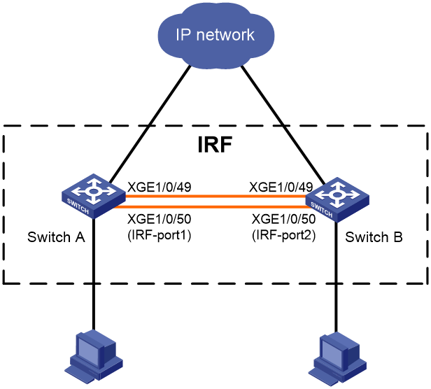
Configuration procedure
|
|
IMPORTANT: · When you connect two neighboring IRF members, you must connect the physical interfaces of IRF port 1 on one member to the physical interfaces of IRF port 2 on the other. · Do not connect physical interfaces of both IRF ports on one member device to the physical interfaces of both IRF ports on the other. |
1. Configure Switch A:
a. From the navigation tree, select Device > Virtualization > IRF.
b. Click the basic settings link, and then access the details page for member device 1 to perform the following tasks:
- Assign a new member ID of 2 to the device.
- Set the priority to 10.
For Switch A to become the master, assign it a higher priority than Switch B.
c. Click the IRF port bindings link, access the details page for IRF-port 1, and then assign XGE 1/0/49 and XGE 1/0/50 to IRF-port 1..
d. Click the advanced link to perform the following tasks:
- Enable auto merge.
- Set the IRF domain ID to 10.
e. Activate IRF port configuration and save the running configuration. Then, reboot the device.
The new member ID takes effect after the reboot.
2. Configure Switch B:
a. From the navigation tree, select Device > Virtualization > IRF.
b. Click the basic settings link, and then access the details page for member device 1 to perform the following tasks:
- Assign a new member ID of 3 to the device.
The IDs of member devices must be unique.
- Use the default priority for the device.
c. Click the IRF port bindings link, access the details page for IRF-port 2, and then assign XGE 1/0/49 and XGE 1/0/50 to IRF-port 2.
The binding mode must be the same at the two ends of an IRF link.
d. Click the advanced link to perform the following tasks:
- Enable auto merge.
- Set the IRF domain ID to be the same as Switch A.
The IRF domain ID must be the same across IRF member devices.
e. Activate IRF port configuration and save the running configuration.
3. Connect Switch B's physical interfaces in IRF-port 2 to Switch A's physical interfaces in IRF-port 1. For more information about connecting IRF ports, see "IRF physical port."
Switch B automatically reboots to form an IRF fabric with Switch A.
Verifying the configuration
1. Log in to the Web interface of Switch A.
2. From the navigation tree, select Device > Virtualization > IRF.
3. Access the topology information page to verify the following items:
¡ The IRF fabric contains member device 2 (Switch A) and member device 3 (Switch B).
¡ The IRF ports are connected.
|
|
NOTE: Support of IRF physical ports and related restrictions depend on the device model. For more information, see the configuration guide of the device. |
Network services configuration examples
Ethernet link aggregation configuration example
Network requirements
As shown in Figure 14, configure static Layer 2 link aggregation on Switch A and Switch B to improve the link reliability.

Configuration procedure
1. Configure Ethernet link aggregation on Switch A:
a. From the navigation tree, select Network > Interfaces > Link Aggregation.
b. Configure a Layer 2 aggregation group on Switch A as follows:
- Configure the aggregation mode as static.
- Assign ports to the aggregation group.
2. Configure the VLAN on Switch A.
a. From the navigation tree, select Network > Links > VLAN.
b. Create VLAN 10.
c. Access the details page for VLAN 10 to perform the following tasks:
- Add the port that connects to Host A to the untagged port list.
- Add ports GigabitEthernet 1/0/1 through GigabitEthernet 1/0/3 to the tagged port list.
3. Configure Switch B in the same way Switch A is configured. (Details not shown.)
Verifying the configuration
1. Access the link aggregation page, and verify that ports GigabitEthernet 1/0/1 through GigabitEthernet 1/0/3 have been assigned to the link aggregation group.
2. Verify that Host A can ping Host B.
3. Verify that Host A can still ping Host B after a link between Switch A and Switch B fails.
Port isolation configuration example
Network requirements
As shown in Figure 15, configure the switch to provide Internet access for all the hosts and isolate them from one another.
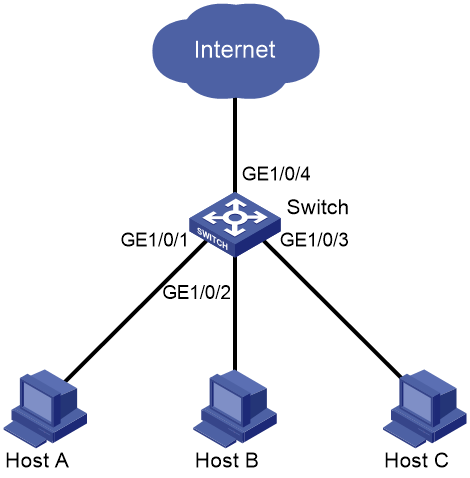
Configuration procedure
1. From the navigation tree, select Network > Interfaces > Port Isolation.
2. Create an isolation group.
3. Access the details page for the isolation group.
4. Assign ports GigabitEthernet 1/0/1 through GigabitEthernet 1/0/3 to the isolation group.
Verifying the configuration
Verify that Host A, Host B, and Host C cannot ping each other.
VLAN configuration example
Network requirements
As shown in Figure 16:
· Host A and Host C belong to Department A. VLAN 100 is assigned to Department A.
· Host B and Host D belong to Department B. VLAN 200 is assigned to Department B.
· On Switch A and Switch B, the link type of GigabitEthernet 1/0/1 is access, the link type of GigabitEthernet 1/0/2 is hybrid, and the link type of GigabitEthernet 1/0/3 is trunk.
Configure VLANs so that only hosts in the same department can communicate with each other.
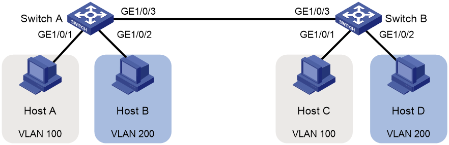
Configuration procedure
1. Configure Switch A:
# Configure link type settings for the ports:
a. From the navigation tree, select Network > Interfaces > Interfaces.
b. Access the details page of GigabitEthernet 1/0/1, and set the link type of the port to access in the VLAN area.
c. Access the details page of GigabitEthernet 1/0/2, and set the link type of the port to hybrid and set the PVID to 200 in the VLAN area.
d. Access the details page of GigabitEthernet 1/0/2, and set the link type of the port to trunk in the VLAN area.
# Configure VLAN settings for the ports:
a. From the navigation tree, select Network > Links > VLAN.
b. Create VLAN 100 and VLAN 200 on Switch A.
c. Access the details page for VLAN 100 to perform the following tasks:
- Add GigabitEthernet 1/0/1 to the untagged port list (Host A cannot recognize VLAN tags).
- Add GigabitEthernet 1/0/3 to the tagged port list (Switch B needs to identify the VLAN tags of packets).
d. Access the details page for VLAN 200 to perform the following tasks:
- Add GigabitEthernet 1/0/2 to the untagged port list (Host B cannot recognize VLAN tags).
- Add GigabitEthernet 1/0/3 to the tagged port list (Switch B needs to identify the VLAN tags of packets).
2. Configure Switch B in the same way Switch A is configured. (Details not shown.)
Verifying the configuration
1. Verify that Host A and Host C can ping each other, but neither of them can ping Host B or Host D.
2. Verify that Host B and Host D can ping each other, but neither of them can ping Host A or Host C.
Voice VLAN configuration example
Network requirements
As shown in Figure 17, IP phone A sends and recognizes only untagged voice packets.
To enable GigabitEthernet 1/0/1 to transmit only voice packets, perform the following tasks on Switch A:
· Create VLAN 2. This VLAN will be used as a voice VLAN.
· Add GigabitEthernet 1/0/1 to VLAN 2.
· Add the OUI address of IP phone A to the OUI list of Switch A.
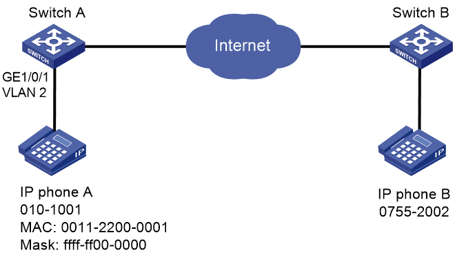
Configuration procedure
1. From the navigation tree, select Network > Interfaces.
2. Set the PVID of GigabitEthernet 1/0/1 as 2.
3. From the navigation tree, select Network > Links > VLAN.
a. Create VLAN 2.
b. Access the details page for VLAN 2, and add GigabitEthernet 1/0/1 to the untagged port list.
4. From the navigation tree, select Network > Links > Voice VLAN.
a. Access the page for selecting ports, assign GigabitEthernet 1/0/1 to VLAN 2, and set the port mode to manual.
b. Access the advanced settings page, and set the mode to security.
c. Access the page for adding an OUI address, and add the OUI address 0011-2200-0000, the mask ffff-ff00-0000, and the description OUI address of IP phone A.
Verifying the configuration
1. View the OUI summary to verify that the OUI address 0011-2200-0000 has been added.
2. View the port summary to verify that GigabitEthernet 1/0/1 has been assigned to voice VLAN 2.
MAC address entry configuration example
Network requirements
As shown in Figure 18:
· Host A at MAC address 000f-e235-dc71 is connected to GigabitEthernet 1/0/1 of the switch and belongs to VLAN 1.
· Host B at MAC address 000f-e235-abcd, which behaved suspiciously on the network, also belongs to VLAN 1.
Configure the MAC address table on the switch as follows:
· To prevent MAC address spoofing, add a static entry for Host A.
· To drop all frames destined for Host B, add a blackhole MAC address entry for Host B.
· Set the aging timer to 500 seconds for dynamic MAC address entries.

Configuration procedure
1. From the navigation tree, select Network > Links > MAC.
2. Add a static MAC address entry for the MAC address 000f-e235-dc71. The outgoing interface is GigabitEthernet 1/0/1, and the VLAN is 1.
3. Add a blackhole MAC address entry for the MAC address 000f-e235-abcd. The VLAN is 1.
4. Access the MAC advanced settings page, and then set the MAC aging timer to 500 seconds.
Verifying the configuration
MSTP configuration example
Network requirements
As shown in Figure 19, all devices in the network are in the same MST region. Switch A and Switch B work at the aggregation layer. Switch C and Switch D work at the access layer.
Configure MSTP so that packets from different VLANs are forwarded along different spanning trees.
· Packets from VLAN 10 are forwarded along MSTI 1.
· Packets from VLAN 30 are forwarded along MSTI 2.
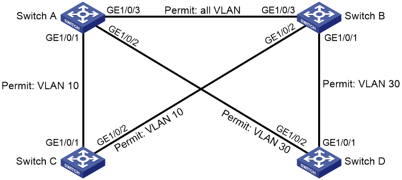
Configuration procedure
1. Configure VLANs:
a. Configure VLANs on Switch A:
- From the navigation tree, select Network > Links > VLAN.
- Create VLAN 10 and VLAN 30.
- Access the details page for VLAN 10. Add ports GigabitEthernet 1/0/1 and GigabitEthernet 1/0/3 to the tagged port list.
- Access the details page for VLAN 30. Add ports GigabitEthernet 1/0/2 and GigabitEthernet 1/0/3 to the tagged port list.
b. Configure VLANs on Switch B:
- From the navigation tree, select Network > Links > VLAN.
- Create VLAN 10 and VLAN 30.
- Access the details page for VLAN 10. Add ports GigabitEthernet 1/0/2 and GigabitEthernet 1/0/3 to the tagged port list.
- Access the details page for VLAN 30. Add ports GigabitEthernet 1/0/1 and GigabitEthernet 1/0/3 to the tagged port list.
c. Configure VLANs on Switch C:
- From the navigation tree, select Network > Links > VLAN.
- Create VLAN 10.
- Access the details page for VLAN 10. Add ports GigabitEthernet 1/0/1 and GigabitEthernet 1/0/2 to the tagged port list.
d. Configure VLANs on Switch D:
- From the navigation tree, select Network > Links > VLAN.
- Create VLAN 30.
- Access the details page for VLAN 30. Add ports GigabitEthernet 1/0/1 and GigabitEthernet 1/0/2 to the tagged port list.
2. Configure MSTP on Switch A through Switch D:
a. From the navigation tree, select Network > Links > STP.
b. Enable STP, and configure the operating mode as MSTP.
c. Access the MST region configuration page to perform the following tasks:
- Configure the MST region name as Web.
- Map VLAN 10 and VLAN 30 to MSTI 1 and MSTI 2, respectively.
- Set the MSTP revision level to 0.
Verifying the configuration
Verify that the port roles and port states in the spanning tree status are as expected.
LLDP configuration example
Network requirements
As shown in Figure 20, configure LLDP on Switch A and Switch B to meet the following requirements:
· Switch A can discover Switch B and obtain system and configuration information from Switch B.
· Switch B cannot discover Switch A.
![]()
Configuration procedure
1. Configure LLDP on switch A:
a. From the navigation tree, select Network > Links > LLDP.
b. Enable LLDP globally.
c. Access the interface status page, and enable LLDP on GigabitEthernet 1/0/1.
d. Access the interface configuration page of advanced settings to perform the following tasks:
- Enable the nearest bridge agent function on GigabitEthernet 1/0/1.
- Configure the interface to only receive LLDP frames.
Then, Switch A can discover neighbors.
2. Configure LLDP on Switch B:
a. From the navigation tree, select Network > Links > LLDP.
b. Enable LLDP globally on Switch B.
c. Access the interface status page, and enable LLDP on GigabitEthernet 1/0/1.
d. Access interface configuration page of advanced settings to perform the following tasks:
- Enable the nearest bridge agent function on GigabitEthernet 1/0/1.
- Configure the interface to only transmit LLDP frames.
Then, Switch B cannot discover neighbors.
Verifying the configuration
2. Verify that the LLDP neighbor information page of Switch B does not contain an entry for Switch A.
DHCP snooping configuration example
Network requirements
As shown in Figure 21, configure DHCP snooping on Switch B to meet the following requirements:
· Allow only the interface that connects to the authorized DHCP server, GigabitEthernet 1/0/1 on Switch B, can forward packets from the DHCP server.
· Record the client IP-MAC binding information in DHCP-REQUEST packets and in DHCP-ACK packets received by GigabitEthernet 1/0/1.
· Save the bindings to the FTP server.

Configuration procedure
1. Configure the DHCP server. (Details not shown.)
2. Configure the FTP server:
Enable the FTP service, and configure the login username and password. (Details not shown.)
3. Configure the DHCP snooping device:
a. From the navigation tree, select Network > Links > DHCP Snooping.
b. Perform the following tasks:
- Enable the DHCP snooping feature.
- Configure GigabitEthernet 1/0/1, the interface that connects to the authorized DHCP server, as the trusted port.
- Configure GigabitEthernet 1/0/2, the interface that connects to the client, to record DHCP snooping entries.
4. Access the advanced settings page to perform the following tasks:
- Save the DHCP snooping entries to a remote server.
- Specify the URL as ftp://10.1.1.1/database.dhcp.
- Specify the username and password for logging into the remote server.
Verifying the configuration
1. Verify that the DHCP client can obtain an IP address and configuration parameters only from the authorized DHCP server.
2. Verify that the DHCP snooping device records the snooping entries.
3. Verify that the DHCP database file on the FTP server saves the DHCP snooping entries.
Static ARP entry configuration example
Network requirements
As shown in Figure 22, configure a static ARP entry for the device on the switch. The static ARP entry prevents spoofing attacks to modify the IP-MAC mapping of the device.
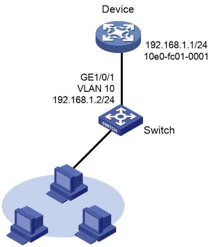
Configuration procedure
1. Configure the VLAN and the VLAN interface:
a. From the navigation tree, select Network > Links > VLAN.
b. Create VLAN 10.
c. Access the details page for VLAN 10 to perform the following tasks:
- Add GigabitEthernet 1/0/1 to the tagged port list.
- Create VLAN-interface 10.
- Assign the IP address 192.168.1.2/24 to VLAN-interface 10.
2. Configure the static ARP entry:
a. From the navigation tree, select Network > IP > ARP.
b. Access the page for adding a static ARP entry to perform the following tasks:
- Configure the IP as 192.168.1.1.
- Configure the MAC address as 10-e0-fc-01-00-01.
- Configure VLAN 10 for the entry.
- Select GigabitEthernet 1/0/1 for the entry.
Verifying the configuration
Verify that the static ARP entry is successfully added.
Static DNS configuration example
Network requirements
As shown in Figure 23, configure a static DNS entry on the device, so the device can use the domain name host.com to access the host at 10.1.1.2.

Configuration procedure
1. Configure the VLAN and VLAN interface:
a. From the navigation tree, select Network > Links > VLAN.
b. Create VLAN 10.
c. Access the details page for VLAN 10 to perform the following tasks:
- Add GigabitEthernet 1/0/1 to the tagged port list.
- Create VLAN-interface 10.
- Assign the IP address 10.1.1.1/24 to VLAN-interface 10.
2. Create a static DNS entry:
a. From the navigation tree, select Network > IP > DNS.
b. Create a static DNS entry:
- Configure the host name as host.com.
- Configure the IPv4 address as 10.1.1.2.
Verifying the configuration
Use the ping host.com command on the switch to verify the following items:
· The ping operation succeeds.
· The switch can use static domain name resolution to resolve domain name host.com into IP address 10.1.1.2.
Dynamic DNS configuration example
Network requirements
As shown in Figure 24, the DNS server at 2.1.1.2/16 has a com domain that stores the mapping between domain name host and IP address 3.1.1.1/16.
Configure dynamic DNS and the DNS suffix com on the device that acts as a DNS client. The device can use the domain name host to access the host with the domain name host.com and the IP address 3.1.1.1/16.
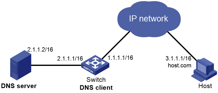
Configuration procedure
1. Configure network routes:
Configure static routes or dynamic routing protocols on each device to make sure the devices can reach each other. (Details not shown.)
2. Configure the DNS server:
Create a mapping between host.com and 3.1.1.1. (Details not shown.)
3. On the switch, configure dynamic DNS:
a. From the navigation tree, select Network > IP > DNS.
b. Configure the IP address of the DNS server as 2.1.1.2.
c. On the advanced settings page, configure the domain name suffix as com.
Verifying the configuration
Use the ping host command on the switch to verify the following items:
· The ping operation succeeds.
· The switch can resolve the domain name host.com into the IP address 3.1.1.1.
Static IPv6 address configuration example
Network requirements
As shown in Figure 25, configure VLAN-interface 10 on the switch to generate an EUI-64 address with the prefix 2001::/64.

Configuration procedure
1. Configure the VLAN and VLAN interface:
a. From the navigation tree, select Network > Links > VLAN.
b. Create VLAN 10.
c. Access the details page for VLAN 10 to perform the following tasks:
- Add GigabitEthernet 1/0/1 to the tagged port list.
- Create VLAN-interface 10.
2. Configure an IPv6 address for VLAN-interface 10:
a. From the navigation tree, select Network > IPv6 > IPv6.
b. Access the details page for VLAN-interface 10 to perform the following tasks:
- Configure the IPv6 address of the interface as 2001::.
- Set the prefix length to 64.
- Select the EUI-64 type.
Verifying the configuration
Verify that the IPv6 addresses of the VLAN-interface:
· The IPv6 global unicast address is 2001::5EDD:70FF:FEB1:86D0.
· A link-local IPv6 address FE80::5EDD:70FF:FEB1:86D0 is automatically generated for the interface.
ND configuration example
Network requirements
As shown in Figure 26, configure IPv6 ND to meet the following requirements:
· VLAN-interface 10 on Switch B sends RA messages to advertise its address prefix.
· VLAN-interface 10 on Switch A generates an IPv6 global unicast addresses through stateless address autoconfiguration.

Configuration procedure
1. Configure Switch B:
a. From the navigation tree, select Network > Links > VLAN.
b. Create VLAN 10.
c. Access the details page for VLAN 10 to perform the following tasks:
- Add GigabitEthernet 1/0/2 to the tagged port list.
- Create VLAN-interface 10.
- Assign the IP address 2001::1/64 to VLAN-interface 10.
d. From the navigation tree, select Network > IPv6 > ND.
e. On the advanced settings page, add an RA prefix:
- Select the interface VLAN-interface 10.
- Configure the prefix address as 2001::1.
- Set the prefix length to 64.
- Set the valid lifetime to 2592000 seconds.
- Set the preferred lifetime to 604800 seconds.
- Select the stateless autoconfiguration method.
f. On the advanced settings page, modify the RA settings:
- Suppress the interface from advertising RA messages.
- Set the maximum interval to 600 seconds for sending RA messages.
- Set the minimum interval to 200 seconds for sending RA messages.
- Set the router lifetime to 1800 seconds.
2. Configure Switch A:
a. From the navigation tree, select Network > Links > VLAN.
b. Create VLAN 10.
c. Access the details page for VLAN 10 to perform the following tasks:
- Add GigabitEthernet 1/0/2 to the tagged port list.
- Create VLAN-interface 10.
d. From the navigation tree, select Network > IPv6 > IPv6.
e. On the details page for VLAN-interface 10, configure the interface to obtain an IPv6 global unicast address through stateless autoconfiguration.
Verifying the configuration
Verify that VLAN-interface 10 of Switch A has generated an IPv6 global unicast address 2001::EDA:41FF:FE5A:2AC8, and the address prefix is the same as that advertised by Switch B.
Port mirroring configuration example
Network requirements
As shown in Figure 27, GigabitEthernet 1/0/1 and GigabitEthernet 1/0/2 of the switch are connected to the marketing department and the technical department, respectively. The switch is connected to the server through GigabitEthernet 1/0/3.

Configuration procedure
1. From the navigation tree, select Network > Mirroring > Port Mirroring.
2. Create a local mirroring group.
3. Configure the local port mirroring group to monitor the incoming and outgoing traffic of ports GigabitEthernet 1/0/1 and GigabitEthernet 1/0/2.
4. Configure GigabitEthernet 1/0/3 as the destination port of the local mirroring group.
Verifying the configuration
IPv4 static route configuration example
Network requirements
As shown in Figure 28, configure IPv4 static routes on the switches for the hosts to communicate with each other.
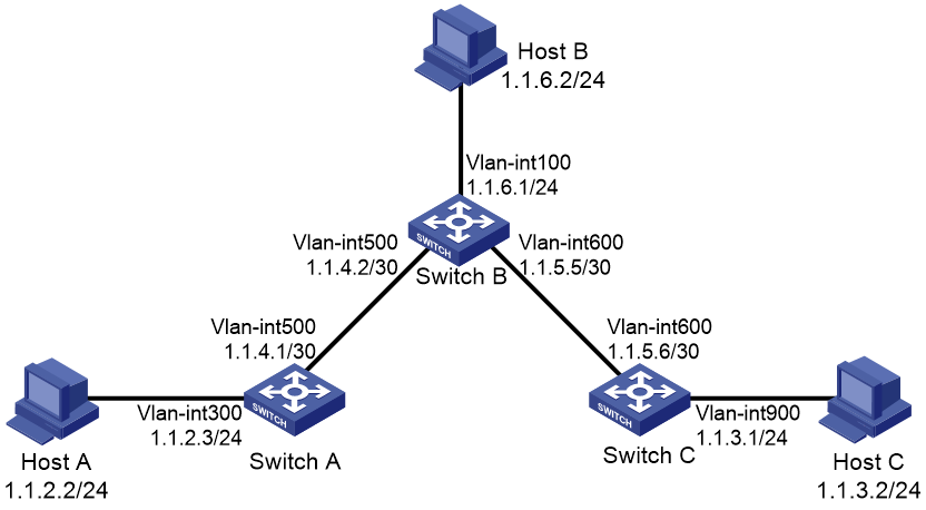
Configuration procedure
1. On Switch A, configure a default route:
a. From the navigation tree, select Network > Routing > Static Routing.
b. Configure the route:
- Set the destination address to 0.0.0.0.
- Set the mask length to 0.
- Set the next hop address to 1.1.4.2 (Switch B).
|
|
NOTE: If the switch has only one uplink port, you only need to configure a default route that points to the upstream device. |
2. On Switch B, configure static routes to reach Host A and Host C:
a. Configure a static route to the network that contains Host A:
- Set the destination address to 1.1.2.0.
- Set the mask length to 24.
- Set the next hop address to 1.1.4.1.
b. Configure a static route to the network that contains Host C:
- Set the destination address to 1.1.3.0.
- Set the mask length to 24.
- Set the next hop address to 1.1.5.6.
3. On Switch C, configure a default route:
¡ Set the destination address to 0.0.0.0.
¡ Set the mask length to 0.
¡ Set the next hop address to 1.1.5.5 (Switch B).
Verifying the configuration
Verify that the hosts can ping each other.
RIP configuration example
Network requirements
As shown in Figure 29, configure RIP on Switch A and Switch B for the hosts to communicate with each other.

Configuration procedure
1. On Switch A, perform the following tasks:
a. From the navigation tree, select Network > Routing > RIP.
b. Enable RIP.
c. Create RIP instance 100.
d. Add network address 1.1.1.0 and subnet mask 255.255.255.0.
e. Add network address 2.1.1.0 and subnet mask 255.255.255.0.
2. On Switch B, perform the following tasks:
a. From the navigation tree, select Network > Routing > RIP.
b. Enable RIP.
c. Create RIP instance 100.
d. Add network address 1.1.1.0 and subnet mask 255.255.255.0.
e. Add network address 10.1.1.0 and subnet mask 255.255.255.0.
Verifying the configuration
Verify that the RIP instances are created and that the hosts can ping each other.
OSPF configuration example
Network requirements
As shown in Figure 30, configure OSPF on Switch A, Switch B, Switch C, and Switch D, and divide the AS into three areas. Switch A and Switch B act as ABRs to forward inter-area routes. Each router can learn routes destined for all subnets in the AS.
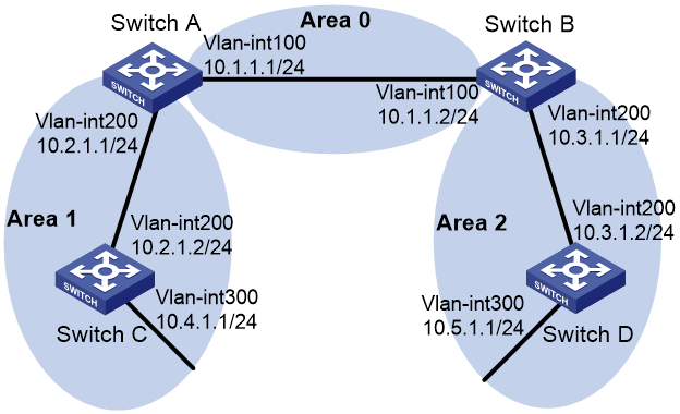
Configuration procedure
1. Access the Network > Routing > OSPF page and configure the following settings:
¡ On Switch A, enable OSPF, create OSPF instance 100, and specify router ID 1.1.1.1 for the OSPF instance.
¡ On Switch B, enable OSPF, create OSPF instance 100, and specify router ID 2.2.2.2 for the OSPF instance.
¡ On Switch C, enable OSPF, create OSPF instance 100, and specify router ID 3.3.3.3 for the OSPF instance.
¡ On Switch D, enable OSPF, create OSPF instance 100, and specify router ID 4.4.4.4 for the OSPF instance.
2. Access the Network > Routing > OSPF > OSPF Area (Instance 100) page and configure the following settings:
On Switch A:
¡ Create an area with area ID 0.0.0.0, specify network address 10.1.1.0 and mask 255.255.255.0 to add subnet 10.1.1.0/24, and add VLAN-interface 100 to the area.
¡ Create an area with area ID 0.0.0.1, specify network address 10.2.1.0 and mask 255.255.255.0 to add subnet 10.2.1.0/24, and add VLAN-interface 200 to the area.
On Switch B:
¡ Create an area with area ID 0.0.0.0, specify network address 10.1.1.0 and mask 255.255.255.0 to add subnet 10.1.1.0/24, and add VLAN-interface 100 to the area.
¡ Create an area with area ID 0.0.0.2, specify network address 10.3.1.0 and mask 255.255.255.0 to add subnet 10.3.1.0/24, and add VLAN-interface 200 to the area.
On Switch C:
¡ Create an area with area ID 0.0.0.1.
¡ Specify network address 10.2.1.0 with mask 255.255.255.0 and network address 10.4.1.0 with mask 255.255.255.0 to add subnets 10.2.1.0/24 and 10.4.1.0/24, respectively, to the area.
¡ Add VLAN-interface 200 and VLAN-interface 300 to the area.
On Switch D:
¡ Create an area with area ID 0.0.0.2.
¡ Specify network address 10.3.1.0 with mask 255.255.255.0 and network address 10.5.1.0 with mask 255.255.255.0 to add subnets 10.3.1.0/24 and 10.5.1.0/24, respectively, to the area.
¡ Add VLAN-interface 200 and VLAN-interface 300 to the area.
Verifying the configuration
# Switch C and Switch D have learned routes destined for all subnets in the AS. (Details not shown.)
BGP configuration example
Network requirements
As shown in Figure 31:
· Enable BGP on Switch A and Switch B for the switches to establish BGP peer relationship.
· On Switch A, import routes in directly connected subnets 2.1.1.1/24 and 3.1.1.1/24 to BGP.
· On Switch B, import routes in subnets 4.1.1.1/24 and 5.1.1.1/24 to BGP.
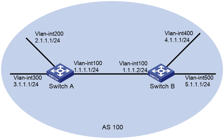
Configuration procedure
1. Configure IP addresses for interfaces. (Details not shown.)
2. Configure BGP:
On Switch A:
a. Access the Network > Routing > BGP page.
b. Enable BGP.
c. Specify AS number 100 for Switch A.
d. Configure the BGP IPv4 unicast address family.
e. Configure an IBGP connection, specify peer IP address 1.1.1.2 and AS number 100, and enable exchange for IPv4 unicast routes.
f. Import direct routes to the BGP IPv4 unicast address family. On Switch A, import routes in subnets 2.1.1.1/24 and 3.1.1.1/24 to BGP for Switch B to obtain routes in the subnets.
On Switch B:
a. Access the Network > Routing > BGP page.
b. Enable BGP.
c. Specify AS number 100 for Switch B.
d. Configure the BGP IPv4 unicast address family.
e. Configure an IBGP connection, specify peer IP address 1.1.1.1 and AS number 100, and enable exchange for IPv4 unicast routes.
f. Import direct routes to the BGP IPv4 unicast address family. On Switch B, import routes in subnets 4.1.1.1/24 and 5.1.1.1/24 to BGP for Switch A to obtain routes in the subnets.
Verifying the configuration
# On Switch B, verify that the BGP peer session with Switch A is in Established state.
# On Switch B, display the BGP routing table to verify that the routing table has routes destined for 2.1.1.1/24 and 3.1.1.1/24.
IPv4 local PBR configuration example
Network requirements
As shown in Figure 32, configure PBR on Switch A to forward all TCP packets to the next hop 1.1.2.2. Switch A forwards other packets according to the routing table.

Configuration procedure
1. From the navigation tree, select Network > Routing > Policy-based Routing.
2. Click IPv4 PBR policies.
3. On the New IPv4 PBR Policy page, perform the following tasks:
a. Enter the policy name pbr, and node number 5.
b. Set the match mode to permit.
c. Select the IPv4 ACL match criterion.
d. Create an IPv4 advanced ACL 3001 and configure a rule to permit TCP packets.
e. Select IPv4 ACL 3001 as the match criterion for the policy pbr.
f. Set the next hop address to 1.1.2.2 for matching packets.
4. Click Forwarding policy of locally generated IP packets and choose pbr to apply the policy to the local device.
Verifying the configuration
1. Verify that Switch A forwards TCP packets to Switch B by using PBR:
¡ Telnet to Switch B from Switch A. The operation succeeds.
¡ Telnet to Switch C from Switch A. The operation fails.
2. Verify that Switch A forwards other packets (ICMP packets, for example) to Switch C according to the routing table:
Ping Switch C from Switch A. The operation succeeds.
IGMP snooping configuration example
Network requirements
As shown in Figure 33:
· The network is a Layer 2-only network.
· Host A and Host B are receivers of multicast group 224.1.1.1.
· All host receivers run IGMPv2, and all switches run IGMPv2 snooping. Switch A (which is close to the multicast source) acts as the IGMP querier.
Configure the switches to meet the following requirements:
· To prevent the switches from flooding unknown packets in the VLAN, enable dropping unknown multicast packets on all the switches.
· A switch does not mark a port that receives an IGMP query with source IP address 0.0.0.0 as a dynamic router port. This adversely affects the establishment of Layer 2 forwarding entries and multicast traffic forwarding. To avoid this situation, configure the source IP address of IGMP queries as a non-zero IP address.
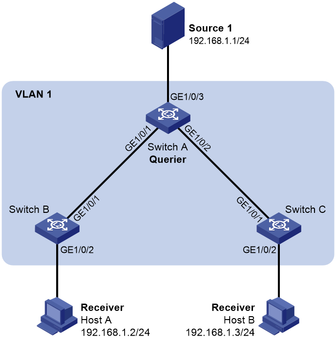
Configuration procedure
1. Configure Switch A:
a. From the navigation tree, select Network > Multicast > IGMP Snooping.
b. Enable IGMP snooping for VLAN 1.
c. Specify the IGMP snooping version as 2.
d. Enable dropping unknown multicast data.
e. Enable the switch to act as the IGMP querier.
f. Set the source IP address to 192.168.1.10 for IGMP general queries and IGMP group-specific queries.
2. Configure Switch B:
a. From the navigation tree, select Network > Multicast > IGMP Snooping.
b. Enable IGMP snooping for VLAN 1.
c. Specify the IGMP snooping version as 2.
d. Enable dropping unknown multicast data.
3. Configure Switch C:
a. From the navigation tree, select Network > Multicast > IGMP Snooping.
b. Enable IGMP snooping for VLAN 1.
c. Specify the IGMP snooping version as 2.
d. Enable dropping unknown multicast data.
Verifying the configuration
1. Send IGMP reports from Host A and Host B to join the multicast group 224.1.1.1.
2. Send multicast data from the source to the multicast group.
3. On the configuration page, click Entries to check that the forwarding entry for the multicast group exists.
MLD snooping configuration example
Network requirements
As shown in Figure 34:
· The network is a Layer 2-only network.
· Host A and Host B are receivers of IPv6 multicast group FF1E::101.
· All host receivers run MLDv1, and all switches run MLDv1 snooping. Switch A (which is close to the multicast source) acts as the MLD querier.
To prevent the switches from flooding unknown packets in the VLAN, enable all the switch to drop unknown IPv6 multicast packets.
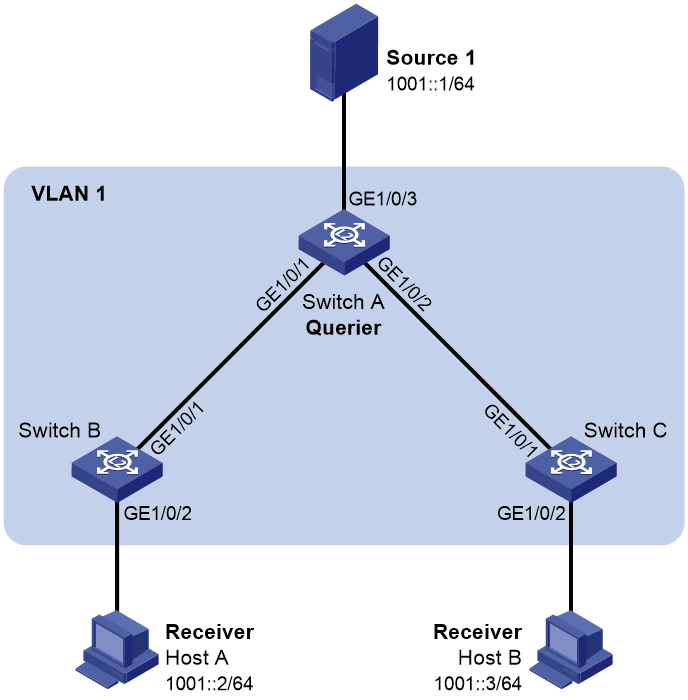
Configuration procedure
1. Configure Switch A:
a. From the navigation tree, select Network > Multicast > MLD Snooping.
b. Enable MLD snooping for VLAN 1.
c. Specify the MLD snooping version as 1.
d. Enable dropping unknown IPv6 multicast data.
e. Enable the switch to act as the MLD querier.
2. Configure Switch B:
a. From the navigation tree, select Network > Multicast > MLD Snooping.
b. Enable MLD snooping for VLAN 1.
c. Specify the MLD snooping version as 1.
d. Enable dropping unknown IPv6 multicast data.
3. Configure Switch C:
a. From the navigation tree, select Network > Multicast > MLD Snooping.
b. Enable MLD snooping for VLAN 1.
c. Specify the MLD snooping version as 1.
d. Enable dropping unknown IPv6 multicast data.
Verifying the configuration
1. Send MLD reports from Host A and Host B to join the IPv6 multicast group FF1E::101.
2. Send multicast data from the source to the IPv6 multicast group.
3. On the configuration page, click Entries to check that the forwarding entry for the IPv6 multicast group exists.
Password authentication enabled Stelnet server configuration example
Network requirements
As shown in Figure 35, the switch acts as the Stelnet server and uses password authentication. The username (client) and password (aabbcc) of the client are saved on the switch.
Establish an Stelnet connection between the host and the switch, so the client can log in to the switch to configure and manage the switch as a network administrator.
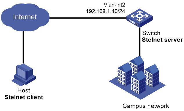
Configuration procedure
1. Configure the Stelnet server to generate RSA, DSA, and ECDSA key pairs:
From the navigation tree, select Resources > Public key > Public key.
2. Configure the Stelnet server feature:
a. From the navigation tree, select Network > Service > SSH.
b. Enable the Stelnet service.
3. Configure the VLAN and VLAN interface:
a. From the navigation tree, select Network > Links > VLAN.
b. Create VLAN 2.
c. Add port GigabitEthernet 1/0/2 to the untagged port list of VLAN 2.
d. Create VLAN-interface 2 and configure its IP address as 192.168.1.40/24.
4. Configure the Stelnet client login authentication method as scheme:
a. Log in to the switch through the console port.
b. Configure the Stelnet client login authentication method as scheme.
5. Configure the administrator account:
a. From the navigation tree, select Device > Maintenance > Administrators.
b. Add an administrator account.
c. Configure the username as client and password as aabbcc.
d. Select the user role as network-admin.
e. Specify the available service as SSH.
Verifying the configuration
There are different types of Stelnet client software, such as PuTTY and OpenSSH. This example uses an Stelnet client that runs PuTTY version 0.58.
To establish a connection to the Stelnet server:
1. Launch PuTTY.exe to enter the interface.
2. In the Host Name (or IP address) field, enter the IP address 192.168.1.40 of the Stelnet server.
3. Click Open to connect to the server.
If the connection is successfully established, the system notifies you to enter the username and password. After entering the username (client in this example) and password (aabbcc in this example), you can enter the CLI of the switch.
DHCP configuration example
Network requirements
As shown in Figure 36, the DHCP client and the DHCP server are on different subnets.
Configure the DHCP relay agent on switch B so that the DHCP client can obtain IP addresses through DHCP.

Configuration procedure
1. Configure the DHCP server:
a. From the navigation tree, select Network > Links > VLAN.
b. Create VLAN 20.
c. Access the details page for VLAN 20 to perform the following tasks:
- Add GigabitEthernet 1/0/2 to the tagged port list.
- Create VLAN-interface 20.
- Assign the IP address 10.1.1.1/24 to VLAN-interface 20.
d. From the navigation tree, select Network > Service > DHCP.
e. On the basic setting page, perform the following tasks:
- Enable DHCP.
- Configure VLAN-interface 20 to operate in the DHCP server mode.
f. Access the address pool configuration page to perform the following tasks:
- Specify the pool name as pool1.
- Specify the subnet as 10.10.1.0/24 for dynamic allocation.
- Specify the gateway IP address as 10.10.1.1.
g. Access the advanced settings page to perform the following tasks:
- Configure the conflict detection feature to send a maximum of one ping packet.
- Specify the timeout time for the response as 500 milliseconds.
2. Configure the DHCP relay agent:
a. From the navigation tree, select Network > Links > VLAN.
b. Create VLAN 10 and VLAN 20.
c. Access the details page for VLAN 10 to perform the following tasks:
- Add GigabitEthernet 1/0/1 to the tagged port list.
- Create VLAN-interface 10.
- Assign the IP address 10.10.1.1/24 to VLAN-interface 10.
d. Access the details page for VLAN 20 to perform the following tasks:
- Add GigabitEthernet 1/0/2 to the tagged port list.
- Create VLAN-interface 20.
- Assign the IP address 10.1.1.2/24 to VLAN-interface 20.
e. From the navigation tree, select Network > Service > DHCP.
f. Perform the following tasks:
- Enable the DHCP service.
- Configure VLAN-interface 10 to operate in DHCP relay agent mode.
- Specify the IP address of the DHCP server as 10.1.1.1.
g. Access the advanced settings page to perform the following tasks:
- Enable the DHCP relay agent to record client information.
- Enable the relay agent to fresh relay entries periodically.
- Set the refresh internal to 100 seconds.
3. Configure the DHCP client:
a. From the navigation tree, select Network > Links > VLAN.
b. Create VLAN 10.
c. Access the details page for VLAN 10 to perform the following tasks:
- Add GigabitEthernet 1/0/1 to the tagged port list.
- Create VLAN-interface 10.
d. From the navigation tree, select Network > IP > IP.
e. Access the details page for VLAN-interface 10 and configure the interface to obtain an IP address through DHCP.
Verifying the configuration
1. Access the Web interface of the DHCP server to verify that the an IP address has been assigned to the DHCP client.
2. Access the Web interface of the DHCP relay agent to verify that a relay entry exists for the assigned IP address.
3. On the DHCP client, verify that the client has obtained the IP address assigned by the DHCP server.
NTP configuration example
Network requirements
As shown in Figure 37:
· Configure the local clock of Device A as a reference source, with the stratum level 2.
· Set Device B to client mode and use Device A as the NTP server for Device B.

Configuration procedure
1. Configure Device A (NTP server):
a. From the navigation tree, select Network > Service > NTP.
b. Enable the NTP service.
c. Specify the IP address of the local clock as 127.127.1.0.
d. Configure the stratum level of the local clock as 2.
2. Configure Device B:
a. From the navigation tree, select Device > Maintenance > Settings.
b. Access the date and time page to select automatic time synchronization with a trusted time source, and then select NTP as the time protocol.
c. Specify the IP address of Device A as 1.0.1.11, and configure Device B to operate in server mode.
Verifying the configuration
Verify that Device B has synchronized to Device A, and the clock stratum level is 3 on Device B and 2 on Device A.
SNMP configuration example
Network requirements
As shown in Figure 38, the NMS (1.1.1.2/24) uses SNMPv2c to manage the SNMP agent (1.1.1.1/24), and the agent automatically sends notifications to report events to the NMS.

Configuration procedure
1. Configure the device:
a. From the navigation tree, select Network > Service > SNMP.
b. Click Enable SNMP to enable the SNMP service.
c. Specify SNMPv2c.
d. Create a read and write community named readandwrite, which can access all nodes in the default MIB view. Configure an IPv4 basic ACL to allow only the SNMPv2c NMS at 1.1.1.2/24 to use community name readandwrite to access the device.
e. Enable traps, and set the destination host to 1.1.1.2, with the security string readandwrite and security model v2c.
2. Configure the SNMP NMS:
a. Specify SNMPv2c.
b. Create read and write community readandwrite.
For information about configuring the NMS, see the NMS manual.
Verifying the configuration
Verify that the NMS can get the value of the sysName node and can receive linkDown notifications when an interface on the device is shut down.
QoS configuration example
Network requirements
As shown in Figure 39, configure QoS to meet the following requirements:
· The traffic of the administration department, R&D department, and marketing department is scheduled in the ratio of 2:1:1.
· The rate of traffic for accessing the Internet is limited to 15 Mbps.
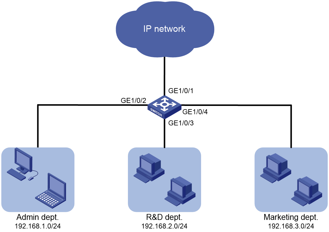
Configuration procedure
1. Configure QoS policies:
a. From the navigation tree, select QoS > QoS > QoS Policy.
b. Apply a QoS policy to the incoming traffic of GigabitEthernet 1/0/2.
c. Access the details page for the QoS policy to modify the applied QoS policy as follows:
- Create IPv4 ACL 2000, and add a rule to permit packets with source IP address 192.168.1.0 and mask 0.0.0.255.
- Configure the ACL as a match criterion of a class, and specify the associated behavior to mark the matched packets with 802.1p priority 0.
d. Apply a QoS policy to the incoming traffic of GigabitEthernet 1/0/3.
e. Access the details page for the QoS policy to modify the applied QoS policy as follows:
- Create IPv4 ACL 2002, and add a rule to permit packets with source IP address 192.168.2.0 and mask 0.0.0.255.
- Configure the ACL as a match criterion of a class, and specify the associated behavior to mark the matched packets with 802.1p priority 1.
f. Apply a QoS policy to the incoming traffic of GigabitEthernet 1/0/4.
g. Access the details page for the QoS policy to modify the applied QoS policy as follows:
- Create IPv4 ACL 2003, and add a rule to permit packets with source IP address 192.168.1.0 and mask 0.0.0.255.
- Configure the ACL as a match criterion of a class, and specify the associated behavior to mark the matched packets with 802.1p priority 2.
2. Configure priority mapping:
a. From the navigation tree, select QoS > QoS > Priority Mapping.
b. Configure GigabitEthernet 1/0/1, GigabitEthernet 1/0/2, GigabitEthernet 1/0/3, and GigabitEthernet 1/0/4 to trust the 802.1p priority.
c. Configure the 802.1p-to-local priority map to map 802.1p priority values 0, 1, and 2 to local precedence values 0, 1, and 2, respectively.
3. Configure hardware queuing:
a. From the navigation tree, select QoS > QoS > Hardware Queuing.
b. Access the details page for GigabitEthernet 1/0/1 to perform the following tasks:
- Configure the queuing algorithm as WRR (byte-count).
- Modify the byte counts of queues 0, 1, and 2 as 2, 1, and 1, respectively.
4. Configure rate limit:
a. From the navigation tree, select QoS > QoS > Rate Limit.
b. Set the CIR to 15360 kbps for the incoming traffic of GigabitEthernet 1/0/1.
Verifying the configuration
Security configuration examples
ACL-based packet filter configuration example
Network requirements
As shown in Figure 40, a company interconnects its departments through the switch. Configure the packet filter to meet the following requirements:
· Permit access from the President's office at any time to the financial database server.
· Permit access from the Financial department to the database server only during working hours (from 8:00 to 18:00) on working days.
· Deny access from any other department to the database server.

Configuration procedure
1. From the navigation tree, select Security > Packet Filter > Packet Filter.
2. Create a packet filter policy:
a. Select VLAN-interface 10.
b. Select the outbound application direction.
c. Select the IPv4 ACL type for packet filter.
3. Create an advanced IPv4 ACL and configure the following rules in the order they are described:
|
Action |
Protocol type |
IP/wildcard mask |
Time range |
|
Permit |
256 |
Source: 192.168.1.0/0.0.0.255 Destination: 192.168.0.100/0 |
N/A |
|
Permit |
256 |
Source: 192.168.2.0/0.0.0.255 Destination: 192.168.0.100/0 |
Create a time range named work: · Specify the start time as 08:00. · Specify the end time as 18:00. · Select Monday through Friday. |
|
Deny |
256 |
Destination: 192.168.0.100/0 |
N/A |
4. Enable rule match counting for the ACL.
Verifying the configuration
1. Ping the database server from different departments to verify the following items:
¡ You can access the server from the President's office at any time.
¡ You can access the server from the Financial department during the working hours.
¡ You cannot access the server from the Marketing department at any time.
2. Access the ACL rule Web interface, verify that the ACL rules are active.
Static IPv4 source guard configuration example
Network requirements
As shown in Figure 41, all hosts use static IP addresses.
Configure static IPv4 source guard entries on Device A and Device B to meet the following requirements:
· GigabitEthernet 1/0/2 of Device A allows only IP packets from Host C to pass.
· GigabitEthernet 1/0/1 of Device A allows only IP packets from Host A to pass.
· GigabitEthernet 1/0/2 of Device B allow only IP packets from Host A to pass.
· GigabitEthernet 1/0/1 of Device B allows only IP packets from Host B to pass.

Configuration procedure
1. Configure Device A:
a. Configure IP addresses for the interfaces. (Details not shown.)
b. From the navigation tree, select Security > Packet Filter > IP Source Guard.
c. Add an IP source guard entry for Host A.
The entry contains interface GigabitEthernet 1/0/1, IP address 192.168.0.1, and MAC address 00-01-02-03-04-06.
d. Add an IP source guard entry for Host C.
The entry contains interface GigabitEthernet 1/0/2, IP address 192.168.0.3, and MAC address 00-01-02-03-04-05.
2. Configure Device B:
a. Configure IP addresses for the interfaces. (Details not shown.)
b. From the navigation tree, select Security > Packet Filter > IP Source Guard.
c. Add an IP source guard entry for Host B.
The entry contains interface GigabitEthernet 1/0/1, IP address 192.168.0.2, and MAC address 00-01-02-03-04-07.
d. Add an IP source guard entry for Host A.
The entry contains interface GigabitEthernet 1/0/2, IP address 192.168.0.1, and MAC address 00-01-02-03-04-06.
Verifying the configuration
1. From the navigation tree, select Security > Packet Filter > IP Source Guard on Device A.
2. Verify that the static IPv4 source guard entries are configured successfully on the IP source guard configuration page.
3. Repeat step 1 and 2 on Device B to verify that the static IPv4 source guard entries are configured successfully.
802.1X RADIUS authentication configuration example
Network requirements
As shown in Figure 42, configure the switch to meet the following requirements:
· Use the RADIUS server to perform authentication, authorization, and accounting for 802.1X users.
· Authenticate all 802.1X users who access the switch through GigabitEthernet 1/0/1 in ISP domain dm1X.
· Use MAC-based access control on GigabitEthernet 1/0/1 to authenticate all 802.1X users on the port separately.
· Exclude domain names from the usernames sent to the RADIUS server.
· Use name as the authentication and accounting shared keys for secure RADIUS communication between the switch and the RADIUS server.
· Use ports 1812 and 1813 for authentication and accounting, respectively.

Configuration procedure
1. Configure IP addresses for the interfaces, as shown in Figure 42. (Details not shown.)
2. Configure a RADIUS scheme on the switch:
a. From the navigation tree, select Security > Authentication > RADIUS.
b. Add RADIUS scheme 802.1X.
c. Configure the primary authentication server:
- Set the IP address to 10.1.1.1.
- Set the authentication port number to 1812.
- Set the shared key to name.
- Set the server state to Active.
d. Configure the primary accounting server:
- Set the IP address to 10.1.1.1.
- Set the accounting port number to 1813.
- Set the shared key to name.
- Set the server state to Active.
e. Configure the switch to not include domain names in the usernames sent to the RADIUS server.
3. Configure an ISP domain on the switch:
a. From the navigation tree, select Security > Authentication > ISP Domains.
b. Add ISP domain dm1X, and set the domain state to Active.
c. Set the access service to LAN access.
d. Configure the ISP domain to use RADIUS scheme 802.1X for authentication, authorization, and accounting of LAN users.
4. Configure 802.1X on the switch:
a. From the navigation tree, select Security > Access Control > 802.1X.
b. Enable 802.1X globally.
c. Enable 802.1X on GigabitEthernet 1/0/1, and set the access control method to MAC-based.
d. On the advanced settings page for GigabitEthernet 1/0/1, set the port authorization state to Auto and set the mandatory ISP domain to dm1X.
5. Configure the RADIUS server:
a. Add a user account on the server. (Details not shown.)
b. Configure the authentication, authorization, and accounting settings. (Details not shown.)
Verifying the configuration
1. From the navigation tree, select Security > Authentication > RADIUS.
2. Verify the configuration of RADIUS scheme 802.1X.
3. From the navigation tree, select Security > Authentication > ISP Domains.
4. Verify the configuration of ISP domain dm1X.
5. Use the configured user account to pass authentication.
6. From the navigation tree, select Security > Access Control > 802.1X.
7. Verify that the number of online users is not 0 on GigabitEthernet 1/0/1.
802.1X local authentication configuration example
Network requirements
As shown in Figure 43, add a user account with username dotuser and password 12345 on the switch. Configure the switch to meet the following requirements:
· Perform local 802.1X authentication to control the network access of users on GigabitEthernet 1/0/1.
· Authenticate the users in ISP domain abc.
· Specify port-based access control on GigabitEthernet 1/0/1. After a user passes authentication on the port, all subsequent users can access the network without authentication.

Configuration procedure
1. Configure IP addresses for the interfaces, as shown in Figure 43. (Details not shown.)
2. Configure the local user account:
a. From the navigation tree, select Security > Authentication > Local Users.
b. Add user account dotuser and set the password to 12345.
c. Set the service type to LAN access.
3. Configure the ISP domain:
a. From the navigation tree, select Security > Authentication > ISP Domains.
b. Add ISP domain abc and set the state to Active.
c. Set the access service to LAN access.
d. Configure the ISP domain to use local method for authentication and authorization of LAN users, and not perform accounting for LAN users.
4. Configure 802.1X:
a. From the navigation tree, select Security > Access Control > 802.1X.
b. Enable 802.1X globally.
c. Enable 802.1X on GigabitEthernet 1/0/1, and set the access control method to port-based.
d. On the advanced settings page for GigabitEthernet 1/0/1, set the port authorization state to Auto and set the mandatory ISP domain to abc.
Verifying the configuration
1. From the navigation tree, select Security > Authentication > Local Users.
2. Verify the configuration of local user dotuser.
3. From the navigation tree, select Security > Authentication > ISP Domains.
4. Verify the configuration of ISP domain abc.
5. Use the user account dotuser and password 12345 to pass authentication.
6. From the navigation tree, select Security > Access Control > 802.1X.
7. Verify that the number of online users is not 0 on GigabitEthernet 1/0/1.
RADIUS-based MAC authentication configuration example
Network requirements
As shown in Figure 44, the switch uses MAC authentication to control Internet access of users on GigabitEthernet 1/0/1.
Configure the switch to meet the following requirements:
· Use the RADIUS server to perform authentication, authorization, and accounting for all users.
· Authenticate all users in ISP domain macauth.
· Use an account with username aaa and password qaz123wdc to identify all users.
· Exclude domain names from the usernames sent to the RADIUS server.
· Use name as the authentication and accounting shared keys for secure RADIUS communication between the switch and the RADIUS server.
· Use ports 1812 and 1813 for authentication and accounting, respectively.
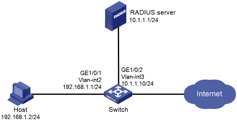
Configuration procedure
1. Configure IP addresses for the interfaces, as shown in Figure 44. (Details not shown.)
2. Configure a RADIUS scheme on the switch:
a. From the navigation tree, select Security > Authentication > RADIUS.
b. Add RADIUS scheme macauth.
c. Configure the primary authentication server:
- Set the IP address to 10.1.1.1.
- Set the authentication port number to 1812.
- Set the shared key to name.
- Set the server state to Active.
d. Configure the primary accounting server:
- Set the IP address to 10.1.1.1.
- Set the accounting port number to 1813.
- Set the shared key to name.
- Set the server state to Active.
e. Configure the switch to not include domain names in the usernames sent to the RADIUS server.
3. Configure an ISP domain on the switch:
a. From the navigation tree, select Security > Authentication > ISP Domains.
b. Add ISP domain macauth, and set the domain state to Active.
c. Set the access service to LAN access.
d. Configure the ISP domain to use RADIUS scheme macauth for authentication, authorization, and accounting of LAN users.
4. Configure MAC authentication on the switch:
a. From the navigation tree, select Security > Access Control > MAC Authentication.
b. Enable MAC authentication globally.
c. Enable MAC authentication on GigabitEthernet 1/0/1.
d. On the advanced settings page, configure the following parameters:
- Set all users to use the same username and password.
- Configure the username as aaa and password as qaz123wdc.
- Specify the authentication domain as macauth.
5. Configure the RADIUS server:
a. Add a user account on the server. (Details not shown.)
b. Configure the authentication, authorization, and accounting settings. (Details not shown.)
Verifying the configuration
1. From the navigation tree, select Security > Authentication > RADIUS.
2. Verify the configuration of RADIUS scheme macauth.
3. From the navigation tree, select Security > Authentication > ISP Domains.
4. Verify the configuration of ISP domain macauth.
5. Use the user account aaa and password qaz123wdc to pass MAC authentication.
6. From the navigation tree, select Security > Access Control > MAC Authentication.
7. Verify that the number of online users is not 0 on GigabitEthernet 1/0/1.
RADIUS-based port security configuration example
Network requirements
As shown in Figure 45, GigabitEthernet 1/0/1 operates in userLoginWithOUI mode to control Internet access of users.
Configure the switch to meet the following requirements:
· Use the RADIUS server to perform authentication, authorization, and accounting for users.
· Use name as the authentication and accounting shared keys for secure RADIUS communication between the switch and the RADIUS server.
· Use ports 1812 and 1813 for authentication and accounting, respectively.
· Authenticate all 802.1X users in ISP domain portsec, and exclude domain names from the usernames sent to the RADIUS server.
· Allow only one 802.1X user and one user whose OUI matches one of the following OUIs to come online on GigabitEthernet 1/0/1:
¡ 1234-0100-1111
¡ 1234-0200-1111
¡ 1234-0300-1111
¡ 1234-0400-1111
¡ 1234-0500-1111

Configuration procedure
1. Configure IP addresses for the interfaces, as shown in Figure 45. (Details not shown.)
2. Configure a RADIUS scheme on the switch:
a. From the navigation tree, select Security > Authentication > RADIUS.
b. Add RADIUS scheme portsec.
c. Configure the primary authentication server:
- Set the IP address to 10.1.1.1.
- Set the authentication port number to 1812.
- Set the shared key to name.
- Set the server state to Active.
d. Configure the primary accounting server:
- Set the IP address to 10.1.1.1.
- Set the accounting port number to 1813.
- Set the shared key to name.
- Set the server state to Active.
e. Configure the switch to not include domain names in the usernames sent to the RADIUS server.
3. Configure an ISP domain on the switch:
a. From the navigation tree, select Security > Authentication > ISP Domains.
b. Add ISP domain portsec, and set the domain state to Active.
c. Set the access service to LAN access.
d. Configure the ISP domain to use RADIUS scheme portsec for authentication, authorization, and accounting of LAN users.
4. Configure port security on the switch:
a. From the navigation tree, select Security > Access Control > Port Security.
b. Enable port security.
c. Set the port security mode to userLoginWithOUI for GigabitEthernet 1/0/1.
d. On the 802.1X tab of the advanced settings page for GigabitEthernet 1/0/1, set the 802.1X mandatory domain to portsec.
e. On the advanced settings page for port security, add five OUI values to the OUI list. The OUI values include 1234-0100-1111, 1234-0200-1111, 1234-0300-1111, 1234-0400-1111, and 1234-0500-1111.
5. Configure the RADIUS server:
a. Add a user account on the server. (Details not shown.)
b. Configure the authentication, authorization, and accounting settings. (Details not shown.)
Verifying the configuration
1. From the navigation tree, select Security > Authentication > RADIUS.
2. Verify the configuration of RADIUS scheme portsec.
3. From the navigation tree, select Security > Authentication > ISP Domains.
4. Verify the configuration of ISP domain portsec.
5. Use the configured user account to pass authentication.
6. From the navigation tree, select Security > Access Control > Port Security.
7. Verify that the number of online users is not 0 on GigabitEthernet 1/0/1.
Direct portal authentication configuration example
Network requirements
As shown in Figure 46, the host is directly connected to the switch (the access device). The host is assigned a public IP address either manually or through DHCP. A portal server acts as both a portal authentication server and a portal Web server. A RADIUS server acts as the authentication/accounting server.
Configure direct portal authentication, so the host can access only the portal server before passing the authentication and access other network resources after passing the authentication.

Configuration procedure
1. Configure the portal server. (Details not shown.)
2. Configure a RADIUS scheme on the switch:
a. From the navigation tree, select Security > Authentication > RADIUS.
b. Add RADIUS scheme rs1.
c. Configure the primary authentication server:
- Set the IP address to 192.168.0.112.
- Set the authentication port number to 1812.
- Set the shared key to radius.
- Set the server state to Active.
d. Configure the primary accounting server:
- Set the IP address to 192.168.0.112.
- Set the accounting port number to 1813.
- Set the shared key to radius.
- Set the server state to Active.
e. Configure the switch to not include domain names in the usernames sent to the RADIUS server.
f. Click the Advanced
settings icon ![]() on the RADIUS page.
on the RADIUS page.
g. Enable the session-control feature.
3. Configure an ISP domain on the switch:
a. From the navigation tree, select Security > Authentication > ISP Domains.
b. Add ISP domain dm1, and set the domain state to Active.
c. Set the access service to Portal.
d. Configure the ISP domain to use RADIUS scheme rs1 for authentication, authorization, and accounting of portal users.
e. Click the Advanced settings icon ![]() on the ISP Domain page.
on the ISP Domain page.
f. Specify dm1 as the default ISP domain. If a user enters the username without the ISP domain name at login, the authentication and accounting methods of the default domain are used for the user.
4. Configure the VLAN and the VLAN interface:
a. From the navigation tree, select Network > Links > VLAN.
b. Create VLAN 100.
c. Open the details page for VLAN 100.
d. Create VLAN-interface 100 and assign IP address 2.2.2.1 to it.
5. Configure portal authentication on the switch:
a. From the navigation tree, select Security > Access Control > Portal.
b. Add a portal authentication server:
- Specify the server name as newpt.
- Specify the IP address as 192.168.0.111.
- Specify the shared key as portal.
- Set the server listening port to 50100.
c. Add a portal Web server:
- Specify the server name as newpt.
- Specify the URL.
The URL must be the same as the URL of the portal Web server used in the network. This example uses http://192.168.0.111:8080/portal.
d. Add an interface policy:
- Select interface VLAN-interface 100.
- In the IPv4 configuration area, enable portal authentication and select the Direct method.
- Select portal Web server newpt.
- Configure the BAS-IP address as 2.2.2.1.
6. Configure the RADIUS server:
a. Add a user account on the server. (Details not shown.)
b. Configure the authentication, authorization, and accounting settings. (Details not shown.)
Verifying the configuration
1. From the navigation tree, select Security > Authentication > RADIUS.
2. Verify the configuration of RADIUS scheme rs1.
3. From the navigation tree, select Security > Authentication > ISP Domains.
4. Verify the configuration of ISP domain dm1.
5. Use the configured user account to pass portal authentication.
6. From the navigation tree, select Security > Access Control > Portal.
7. Verify that the number of online users is not 0 on VLAN-interface 100.
Cross-subnet portal authentication configuration example
Network requirements
As shown in Figure 47, Switch A supports portal authentication. The host accesses Switch A through Switch B. A portal server acts as both a portal authentication server and a portal Web server. A RADIUS server acts as the authentication/accounting server.
Configure Switch A for cross-subnet portal authentication. Before passing the authentication, the host can access only the portal Web server. After passing the authentication, the user can access other network resources.
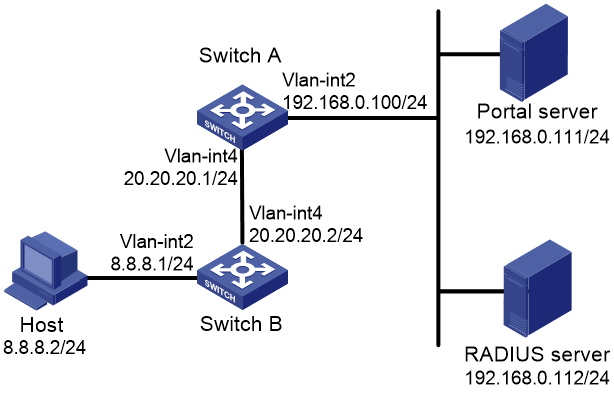
Configuration procedure
1. Configure the portal server. (Details not shown.)
2. Configure a RADIUS scheme on Switch A:
a. From the navigation tree, select Security > Authentication > RADIUS.
b. Add RADIUS scheme rs1.
c. Configure the primary authentication server:
- Set the IP address to 192.168.0.112.
- Set the authentication port number to 1812.
- Set the shared key to radius.
- Set the server state to Active.
d. Configure the primary accounting server:
- Set the IP address to 192.168.0.112.
- Set the accounting port number to 1813.
- Set the shared key to radius.
- Set the server state to Active.
e. Configure the switch to not include domain names in the usernames sent to the RADIUS server.
f. Click the Advanced
settings icon ![]() on the RADIUS page.
on the RADIUS page.
g. Enable the session-control feature.
3. Configure an ISP domain on Switch A:
a. From the navigation tree, select Security > Authentication > ISP Domains.
b. Add ISP domain dm1, and set the domain state to Active.
c. Set the access service to Portal.
d. Configure the ISP domain to use RADIUS scheme rs1 for authentication, authorization, and accounting of portal users.
e. Click the Advanced settings icon ![]() on the ISP Domain page.
on the ISP Domain page.
f. Specify dm1 as the default ISP domain. If a user enters the username without the ISP domain name at login, the authentication and accounting methods of the default domain are used for the user.
4. Configure the VLAN and the VLAN interface on Switch A:
a. From the navigation tree, select Network > Links > VLAN.
b. Create VLAN 4.
c. Open the details page for VLAN 4.
d. Create VLAN-interface 4 and assign IP address 20.20.20.1 to it.
5. Configure portal authentication on Switch A:
a. From the navigation tree, select Security > Access Control > Portal.
b. Add a portal authentication server:
- Specify the server name as newpt.
- Specify the IP address as 192.168.0.111.
- Specify the shared key as portal.
- Set the server listening port to 50100.
c. Add a portal Web server:
- Specify the server name as newpt.
- Specify the URL.
The URL must be the same as the URL of the portal Web server used in the network. This example uses http://192.168.0.111:8080/portal.
d. Add an interface policy:
- Select interface VLAN-interface 4.
- In the IPv4 configuration area, enable portal authentication and select the Layer3 method.
- Select portal Web server newpt.
- Configure the BAS-IP address as 20.20.20.1.
6. Configure the RADIUS server:
a. Add a user account on the server. (Details not shown.)
b. Configure the authentication, authorization, and accounting settings. (Details not shown.)
Verifying the configuration
1. From the navigation tree, select Security > Authentication > RADIUS.
2. Verify the configuration of RADIUS scheme rs1.
3. From the navigation tree, select Security > Authentication > ISP Domains.
4. Verify the configuration of ISP domain dm1.
5. Use the configured user account to pass portal authentication.
6. From the navigation tree, select Security > Access Control > Portal.
7. Verify that the number of online users is not 0 on VLAN-interface 4.
Direct portal authentication using local portal Web server configuration example
Network requirements
As shown in Figure 48, the host is directly connected to the switch (the access device). The host is assigned a public IP address either manually or through DHCP. The switch acts as both a portal authentication server and a portal Web server. A RADIUS server acts as the authentication/accounting server.
Configure direct portal authentication on the switch. Before a user passes portal authentication, the user can access only the local portal Web server. After passing portal authentication, the user can access other network resources.

Configuration procedure
1. Configure a RADIUS scheme on the switch:
a. From the navigation tree, select Security > Authentication > RADIUS.
b. Add RADIUS scheme rs1.
c. Configure the primary authentication server:
- Set the IP address to 192.168.0.112.
- Set the authentication port number to 1812.
- Set the shared key to radius.
- Set the server state to Active.
d. Configure the primary accounting server:
- Set the IP address to 192.168.0.112.
- Set the accounting port number to 1813.
- Set the shared key to radius.
- Set the server state to Active.
e. Configure the switch to not include domain names in the usernames sent to the RADIUS server.
f. Click the Advanced
settings icon ![]() on the RADIUS page.
on the RADIUS page.
g. Enable the session-control feature.
2. Configure an ISP domain on the switch:
a. From the navigation tree, select Security > Authentication > ISP Domains.
b. Add ISP domain dm1, and set the domain state to Active.
c. Set the access service to Portal.
d. Configure the ISP domain to use RADIUS scheme rs1 for authentication, authorization, and accounting of portal users.
e. Click the Advanced settings icon ![]() on the ISP Domain page.
on the ISP Domain page.
f. Specify dm1 as the default ISP domain. If a user enters the username without the ISP domain name at login, the authentication and accounting methods of the default domain are used for the user.
3. Configure the VLAN and the VLAN interface on Switch A:
a. From the navigation tree, select Network > Links > VLAN.
b. Create VLAN 100.
c. Open the details page for VLAN 100.
d. Create VLAN-interface 100 and assign IP address 2.2.2.1 to it.
4. Configure portal authentication on the switch:
a. From the navigation tree, select Security > Access Control > Portal.
b. Add a portal Web server:
- Specify the server name as newpt.
- Specify the URL as http://2.2.2.1:2331/portal.
The URL can be the IP address of the interface enabled with portal authentication or a loopback interface's address other than 127.0.0.1.
c. Add a local portal Web server:
- Select HTTP.
- Select the default logon page abc.zip.
The default logon page file must have existed in the root directory of the switch's storage medium.
- Set the TCP port to 2331.
d. Add an interface policy:
- Select interface VLAN-interface 100.
- In the IPv4 configuration area, enable portal authentication and select the Direct method.
- Select portal Web server newpt.
5. Configure the RADIUS server:
a. Add a user account on the server. (Details not shown.)
b. Configure the authentication, authorization, and accounting settings. (Details not shown.)
Verifying the configuration
1. From the navigation tree, select Security > Authentication > RADIUS.
2. Verify the configuration of RADIUS scheme rs1.
3. From the navigation tree, select Security > Authentication > ISP Domains.
4. Verify the configuration of ISP domain dm1.
5. Use the configured user account to pass portal authentication.
6. From the navigation tree, select Security > Access Control > Portal.
7. Verify that the number of online users is not 0 on VLAN-interface 100.
AAA for SSH users by a TACACS server configuration example
Network requirements
As shown in Figure 49, configure the switch to meet the following requirements:
· Use the TACACS server for SSH user authentication, authorization, and accounting.
· Assign the default user role network-admin to SSH users after they pass authentication.
· Exclude domain names from the usernames sent to the TACACS server.
· Use expert as the shared keys for secure TACACS communication.
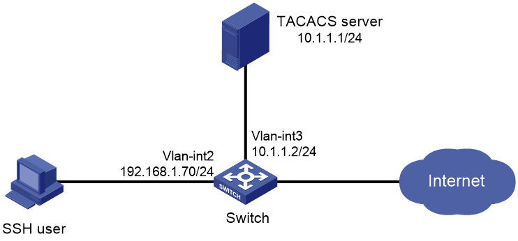
Configuration procedure
1. Configure the Stelnet server to generate local key pairs for SSH:
a. From the navigation tree, select Resources > Public key > Public key.
b. Add local DSA, ECDSA, and RSA key pairs.
2. Configure the SSH server:
a. From the navigation tree, select Network > Service > SSH.
b. Enable the Stelnet service.
3. Configure the VLAN and VLAN interface:
a. From the navigation tree, select Network > Links > VLAN.
b. Create VLAN 2.
c. Access the details page for VLAN 2 to perform the following tasks:
- Add interface GigabitEthernet 1/0/2 to the tagged port list.
- Create VLAN-interface 2.
- Assign IP address 192.168.1.70/24 to VLAN-interface 2.
4. Configure a TACACS scheme on the switch:
a. From the navigation tree, select Security > Authentication > TACACS.
b. Add TACACS scheme tac.
c. Configure the primary authentication, authorization, and accounting servers:
- Set the IP address to 10.1.1.1.
- Set the port number to 49.
- Set the shared key to expert.
d. In advanced settings, configure the switch to exclude domain names in the user names sent to the TACACS server.
5. Configure an ISP domain on the switch:
a. From the navigation tree, select Security > Authentication > ISP Domains.
b. Add ISP domain bbb and set the domain state to Active.
c. Select Login as the service type.
d. Configure the ISP domain to use TACACS scheme tac for authentication, authorization, and accounting of login users.
6. Configure the user lines for the Stelnet client:
a. Log in to the switch through the console port.
b. Set the login authentication mode to scheme. (Details not shown.)
7. Configure the TACACS server:
a. Add a user account on the server. (Details not shown.)
b. Configure the authentication, authorization, and accounting settings. (Details not shown.)
c. Configure the user role feature to assign authenticated SSH users the network-admin user role. (Details not shown.)
Verifying the configuration
1. Initiate an SSH connection to the switch and enter the correct username and password. The user logs in to the switch.
2. Verify that the user can use the commands permitted by the network-admin user role.
PoE configuration example
Network requirements
As shown in Figure 50, configure PoE to meet the following requirements:
· Enable the device to supply power to IP telephones and the AP.
· Enable the device to supply power to IP telephones first when overload occurs.
· Allocate AP a maximum power of 9000 milliwatts.
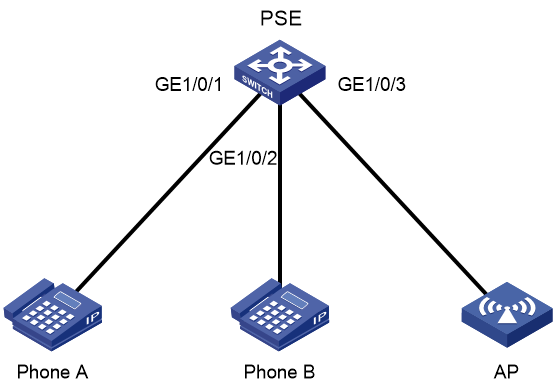
Configuration procedure
1. From the navigation tree, select PoE > PoE.
2. Enable PoE for GigabitEthernet 1/0/1 and GigabitEthernet 1/0/2, set the power supply priority to critical.
3. Enable PoE for GigabitEthernet 1/0/3 and set the maximum PoE power for the interface to 9000 milliwatts.
SmartMC configuration example
Network requirements
As shown in Figure 51, TM is the management device and TC 1 to TC 3 are member devices. On the management device, configure interface GigabitEthernet 1/0/1 as the outgoing interface of the SmartMC network and upgrade the configuration files of all member devices in a SmartMC group.
· All member devices are S5560-EI switches.
· The host is connected to the management device through GigabitEthernet 1/0/1. The IP addresses of the host and GigabitEthernet 1/0/1 belong to subnet 192.168.56.0/24. The IP addresses of the management device and VLAN-interface 1 on each member device belong to subnet 192.168.2.0/24.
· The IP address of the FTP server is 192.168.2.1, the username is admin, and the password is admin.
· The configuration file name is startup.cfg. The file is stored on the FTP server.

Configuration procedure
1. Configure IP addresses for the management device, member devices, FTP server, and host to make sure they can reach one another. (Details not shown.)
2. Log in to the Web interface of TM and access the SmartMC management page.
a. Access the Management IP address page, configure the management IP address as 192.168.2.2, and set the mask length to 24.
b. Access the Outgoing interface page and configure GigabitEthernet 1/0/1 as the outgoing interface.
c. Access the Management user page, set the username to admin, and set the password to admin.
d. Complete the configuration.
3. Start up the member devices. Make sure the member devices have finished automatic configuration and started up successfully.
4. Configure the FTP server:
a. Access the Intelligent Management > File server page.
b. Set the address of the FTP server to 192.168.2.1, the FTP username to admin, and the password to admin.
5. Create a SmartMC group:
a. Access the Intelligent O&M > SmartMC group page.
b. Click Add.
c. Specify group name S1 and use IP address as the match rule type. Specify IP address 192.168.2.0 and mask length 24.
6. Configure an upgrade configuration file for the SmartMC group:
a. Access the Intelligent O&M > Upgrade page.
b. Select SmartMC groups as the operation object.
c. Click the Edit icon for SmartMC group S1. Configure an upgrade file for the group, select configuration file as the upgrade file type, and set the configuration file name to startup.cfg.
7. Immediately upgrade the configuration file of the SmartMC group:
a. Select SmartMC group S1, and click Upgrade in the upper right corner.
b. Select configuration file as the upgrade object, and select immediately as the upgrade time.
c. Click Certain.
Verifying the configuration
# Log in to the Web interface of TM, access the Visibility > Topology page, and verify the SmartMC network topology.
Figure 52 SmartMC network topology
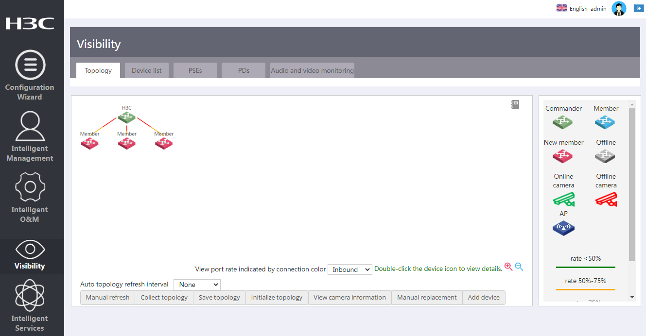
# On the Visibility > Topology page, select TC 1 and click Log in to Web interface. Verify that you can access the Web interface of TC 1.
Figure 53 Web interface of TC 1
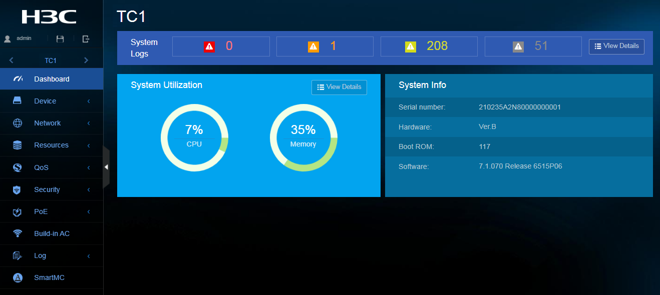
# On TM, access the Intelligent O&M > Upgrade page, and then click View upgrade status. Verify that the configuration file upgrade has succeeded on each member device.
WiNet configuration example
Network requirements
As shown in Figure 54, TM is the management device and TC 1 to TC 3 are member devices. On the management device, configure interface GigabitEthernet 1/0/1 as the outgoing interface of the WiNet network and upgrade the configuration files of all member devices in a WiNet group.
· All member devices are WS5850-WiNet switches.
· The host is connected to the management device through GigabitEthernet 1/0/1. The IP addresses of the host and GigabitEthernet 1/0/1 belong to subnet 192.168.56.0/24. The IP addresses of the management device and VLAN-interface 1 on each member device belong to subnet 192.168.2.0/24.
· The IP address of the FTP server is 192.168.2.1, the username is admin, and the password is admin.
· The configuration file name is startup.cfg. The file is stored on the FTP server.
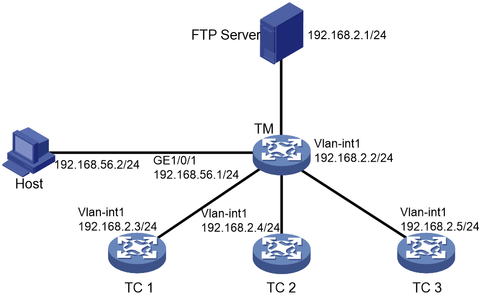
Configuration procedure
1. Configure IP addresses for the management device, member devices, FTP server, and host to make sure they can reach one another. (Details not shown.)
2. Log in to the Web interface of TM and access the WiNet management page.
a. Access the Management IP address page, configure the management IP address as 192.168.2.2, and set the mask length to 24.
b. Access the Outgoing interface page and configure GigabitEthernet 1/0/1 as the outgoing interface.
c. Access the Management user page, set the username to admin, and set the password to admin.
d. Complete the configuration.
3. Start up the member devices. Make sure the member devices have finished automatic configuration and started up successfully.
4. Configure the FTP server:
a. Access the Intelligent Management > File server page.
b. Set the address of the FTP server to 192.168.2.1, the FTP username to admin, and the password to admin.
5. Create a WiNet group:
a. Access the Intelligent O&M > WiNet group page.
b. Click Add.
c. Specify group name S1 and use IP address as the match rule type. Specify IP address 192.168.2.0 and mask length 24.
6. Configure an upgrade configuration file for the WiNet group:
a. Access the Intelligent O&M > Upgrade page.
b. Select WiNet groups as the operation object.
c. Click the Edit icon for WiNet group S1. Configure an upgrade file for the group, select configuration file as the upgrade file type, and set the configuration file name to startup.cfg.
7. Immediately upgrade the configuration file of the WiNet group:
a. Select WiNet group S1, and click Upgrade in the upper right corner.
b. Select configuration file as the upgrade object, and select immediately as the upgrade time.
c. Click Certain.
Verifying the configuration
# Log in to the Web interface of TM, access the Visibility > Topology page, and verify the WiNet network topology.
Figure 55 WiNet network topology
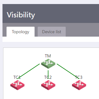
# On the Visibility > Topology page, select TC 1 and click Log in to Web interface. Verify that you can access the Web interface of TC 1.
Figure 56 Web interface of TC 1

# On TM, access the Intelligent O&M > Upgrade page, and then click View upgrade status. Verify that the configuration file upgrade has succeeded on each member device.
Web-based configuration cautions and guidelines
This guide contains important information that if not understood or followed can result in undesirable situations, including:
· Unexpected shutdown or reboot of devices or cards.
· Service anomalies or interruption.
· Loss of data, configuration, or important files.
· User login failure or unexpected logoff.
Only trained and qualified personnel are allowed to do the configuration tasks described in this guide.
Before you configure your device, read the information in this document carefully.
Device-Maintenance
Deleting an administrator user account
Consequences
After an administrator user account is deleted, users cannot log in to the device with that user account.
Procedure
1. From the navigation pane, select Device > Maintenance > Administrators.
2. Delete an administrator user account.
Figure 57 Deleting an administrator user account
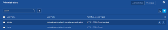
Modifying the password of a user account
Consequences
If you modify the password of a user account, users that do not know the new password cannot log in to the device with the user account.
Recommendation
After you modify the password of a user account, record the new password and notify users that use the user account of the new password.
Procedure
1. From the navigation pane, select Device > Maintenance > Administrators.
2. Click the Details icon for a user account.
3. Enter a password and confirm the password.
Figure 58 Modifying the password of a user account
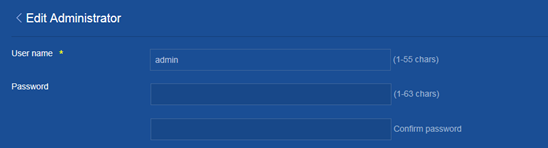
Disabling a user account permanently after the maximum number of consecutive login attempts is reached
Consequences
With password control enabled, this operation prevents a user from using its IP address to access the device after the maximum number of consecutive login attempts is reached.
Procedure
1. From the navigation pane, select Device > Maintenance > Administrators.
2. Click the Password control icon at the upper right corner of the page.
3. Click Enable Password Control.
4. Select Disables the user account permanently in the User login area.
Figure 59 Disabling a user account permanently
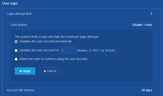
Saving the running configuration
Consequences
Saving the running configuration might overwrite the settings in an existing configuration file.
Recommendation
Perform this operation according to the system prompt.
Procedure
1. From the navigation pane, select Device > Maintenance > Configuration.
2. Click Save Running Configuration.
Figure 60 Saving the running configuration
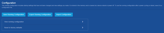
Importing configuration
Consequences
This operation rolls back the running configuration to the configuration in the specified configuration file. The configuration before the rollback is lost.
This operation might cause service interruption.
Procedure
1. From the navigation pane, select Device > Maintenance > Configuration.
2. Click Import Configuration.
Figure 61 Importing configuration

Restoring the factory defaults
Consequences
This operation deletes next-startup configuration files from the device and restores the device configuration to the factory defaults.
Procedure
1. From the navigation pane, select Device > Maintenance > Configuration.
2. Click the ![]() icon
next to Reset to factory
defaults.
icon
next to Reset to factory
defaults.
3. Click Reset.
Figure 62 Restoring the factory defaults

Deleting a file or file folder
Consequences
Deleted files and file folders cannot be recovered.
Procedure
1. From the navigation pane, select Device > Maintenance > File System.
2. Delete a file or file folder.
Figure 63 Deleting a file or file folder
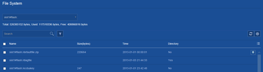
Upgrading startup software images
Consequences
This operation might cause service interruption.
Procedure
1. From the navigation pane, select Device > Maintenance > Upgrade.
2. Upgrade startup software images.
Figure 64 Upgrading startup software images
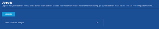
Rebooting the device
Consequences
This operation might cause service interruption.
Procedure
1. From the navigation pane, select Device > Maintenance > Reboot.
2. Reboot the device.
Figure 65 Rebooting the device

Device-Virtualization
Changing the member ID of an IRF member device
Consequences
On an IRF fabric, an IRF member ID change can invalidate member ID-related settings and cause data loss.
If the new member ID is the same as the member ID of another member device in the IRF fabric, the current device cannot join the IRF fabric after it reboots.
Procedure
1. From the navigation pane, select Device > Virtualization > IRF.
2. Click the ![]() icon
next to Basic settings.
icon
next to Basic settings.
3. Click the Details icon for an IRF member device.
4. Change the member ID of the IRF member device.
Figure 66 Changing the member ID of an IRF member device
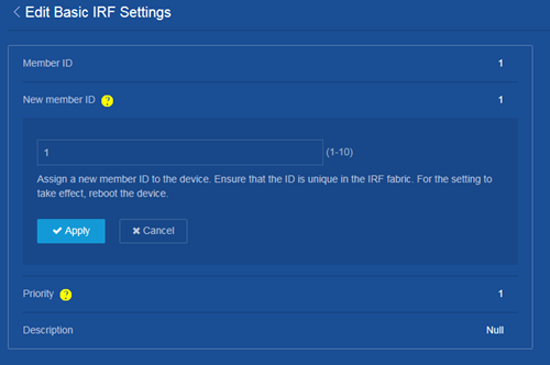
Modifying IRF port bindings
Consequences
This operation might cause IRF split or traffic forwarding issue.
Procedure
1. From the navigation pane, select Device > Virtualization > IRF.
2. Click the ![]() icon
next to IRF port bindings.
icon
next to IRF port bindings.
3. Click the Details icon for an IRF member device.
4. Modify the IRF physical interfaces bound to an IRF port.
Figure 67 Modifying IRF port bindings
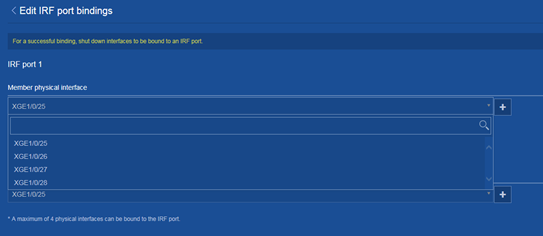
Changing the IRF domain ID
Consequences
This operation might result in IRF domain ID conflict in a network that has multiple IRF fabrics. IRF domain ID conflict can cause MAD to mistakenly place an IRF fabric in Recovery state or cause IRF split.
Procedure
1. From the navigation pane, select Device > Virtualization > IRF.
2. Click the ![]() icon
next to Advanced settings.
icon
next to Advanced settings.
3. Change the IRF domain ID.
Figure 68 Changing the IRF domain ID
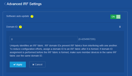
Changing the IRF bridge MAC persistent time
Consequences
This operation might affect traffic forwarding on an IRF fabric.
Procedure
1. From the navigation pane, select Device > Virtualization > IRF.
2. Click the ![]() icon
next to Advanced settings.
icon
next to Advanced settings.
3. Change the IRF bridge MAC persistence setting.
Figure 69 Changing the IRF bridge MAC persistent time
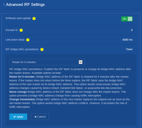
Network-Interfaces
Restoring the default settings of an interface
Consequences
This operation might interrupt ongoing network services. Make sure you are fully aware of the impact of this operation when you perform it on a live network.
Procedure
1. From the navigation pane, select Network > Interfaces > Interfaces.
2. Select one or multiple interfaces and click Default at the bottom of the page.
Figure 70 Restoring the default settings of an interface
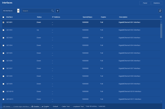
Shutting down an interface
Consequences
Shutting down an interface disconnects the links attached to the interface and might cause communication disruption.
Procedure
1. From the navigation pane, select Network > Interfaces > Interfaces.
2. Click the Details icon for an interface.
3. Shut down the interface.
Figure 71 Shutting down an interface
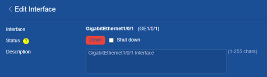
Network-IP
Deleting all dynamic ARP entries
Consequences
This operation clears all dynamic ARP entries on the device. In this situation, the device might fail to forward external traffic to internal users.
Procedure
1. From the navigation pane, select Network > IP > ARP.
2. Delete all dynamic entries from the device.
Figure 72 Deleting all dynamic ARP entries
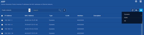
Network-Routing
Deleting all IPv4 static routes
Consequences
Deleting all IPv4 static routes might cause network reachability issues and packet forwarding failures.
Procedure
1. From the navigation pane, select Network > Routing > Static Routing.
2. Click the ![]() icon
next to IPv4 static routing.
icon
next to IPv4 static routing.
3. Delete all IPv4 static routes.
Figure 73 Deleting all IPv4 static routes
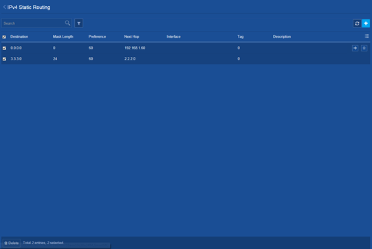
Deleting all IPv6 static routes
Consequences
Deleting all IPv6 static routes might cause network reachability issues and packet forwarding failures.
Procedure
1. From the navigation pane, select Network > Routing > Static Routing.
2. Click the ![]() icon
next to IPv6 static routing.
icon
next to IPv6 static routing.
3. Delete all IPv6 static routes.
Figure 74 Deleting all IPv6 static routes
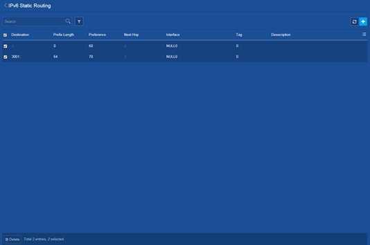
Network-Network services
Disabling the HTTP or HTTPS service
Consequences
If the HTTP or HTTPS service is disabled, users cannot access the device through the Web interface.
Procedure
1. From the navigation pane, select Network > Service > HTTP/HTTPS.
2. Change the state of the HTTP or HTTPS service from ON to OFF.
Figure 75 Disabling the HTTP or HTTPS service
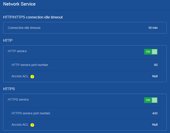
Intelligent O&M
Upgrading the startup software or configuration file for members or SmartMC groups
Consequences
Upgrading the startup software images might interrupt services.
After you upgrade the configuration file of a member, the member will run the configuration in the specified configuration file. The original configuration of the member is lost.
Procedure
1. From the navigation pane, click SmartMC.
2. From the navigation pane on the page that opens, click Intelligent O&M.
3. Click the Upgrade tab.
4. Select one or multiple members or SmartMC groups, and then click Upgrade.
5. Upgrade the startup software or configuration file.
Figure 76 Upgrading the startup software or configuration file for members or SmartMC groups
Intelligent O&M
Upgrading the startup software or configuration file for members or WiNet groups
Consequences
Upgrading the startup software images might interrupt services.
After you upgrade the configuration file of a member, the member will run the configuration in the specified configuration file. The original configuration of the member is lost.
Procedure
1. From the navigation pane, click WiNet.
2. From the navigation pane on the page that opens, click Intelligent O&M.
3. Click the Upgrade tab.
4. Select one or multiple members or WiNet groups, and then click Upgrade.
5. Upgrade the startup software or configuration file.
Figure 77 Upgrading the startup software or configuration file for members or WiNet groups
