- Table of Contents
-
- 07-MPLS Configuration Guide
- 00-Preface
- 01-Basic MPLS configuration
- 02-SR-MPLS configuration
- 03-Static LSP configuration
- 04-LDP configuration
- 05-MPLS TE configuration
- 06-Static CRLSP configuration
- 07-RSVP configuration
- 08-Tunnel policy configuration
- 09-MPLS L3VPN configuration
- 10-MPLS L2VPN configuration
- 11-VPLS configuration
- 12-MPLS OAM configuration
- 13-MCE configuration
- Related Documents
-
| Title | Size | Download |
|---|---|---|
| 12-MPLS OAM configuration | 219.25 KB |
Contents
About LSP connectivity verification
Performing MPLS tracert for LSPs
Configuring periodic MPLS tracert for LSPs
Verifying MPLS TE tunnel connectivity
About MPLS TE tunnel connectivity verification
Performing MPLS ping for MPLS TE tunnels
Performing MPLS tracert for MPLS TE tunnels
Configuring BFD control packet mode for MPLS TE tunnels
Configuring BFD echo packet mode for MPLS TE tunnels
Configuring SBFD for MPLS TE tunnels
About PW connectivity verification
Display and maintenance commands for MPLS OAM
MPLS OAM configuration examples
Example: Configuring BFD for LSP
Example: Configuring BFD for PW
Configuring MPLS OAM
About MPLS OAM
· MPLS data plane connectivity verification.
· Data plane and control plane consistency verification.
· Fault locating.
Fault management tools
The fault management tools include the following types:
· On-demand tools—Tools that must be triggered manually, such as MPLS ping and MPLS tracert.
· Proactive tools—Tools that are triggered by the system automatically, such as BFD for MPLS, and periodic MPLS tracert.
Support for the fault management tools varies by MPLS tunnel type.
· LSP tunnels support all tools.
· MPLS TE tunnels do not support periodic MPLS tracert.
· MPLS PWs do not support MPLS tracert and periodic MPLS tracert.
MPLS ping
MPLS ping tests the connectivity of a tunnel. At the ingress node, MPLS ping adds the label associated with a tunnel into an MPLS echo request and sends it to the egress node over the tunnel. The egress node processes the request and returns an MPLS echo reply to the ingress node. An MPLS echo reply with a success notification indicates that the tunnel is available for data forwarding. An MPLS echo reply with an error code indicates that the tunnel has failed.
MPLS tracert
MPLS tracert displays the path that a tunnel travels from the ingress to the egress to locate errors on the tunnel. MPLS tracert consecutively sends MPLS echo requests along the tunnel, with the TTL increasing from 1 to a specific value. Each hop along the tunnel returns an MPLS echo reply to the ingress due to TTL timeout so the ingress can collect information about each hop along the tunnel. This information allows you to locate the failed node or access information for each hop, for example, the label allocated by each downstream hop.
BFD for MPLS
BFD for MPLS uses a BFD session to proactively verify the connectivity of a tunnel.
MPLS supports two BFD detection modes: control packet mode and echo packet mode. In echo packet mode, BFD for MPLS can verify the connectivity of only MPLS TE tunnels.
BFD control packet mode
The BFD control packet mode for MPLS performs the following operations:
1. Establishes a BFD session between the ingress and egress of the tunnel to be inspected.
2. Adds the label associated with the tunnel into a BFD control packet at the ingress.
3. Sends the packet to the egress node over the tunnel.
4. Determines the tunnel status according to the BFD control packet returned by the egress.
When BFD detects a connectivity failure, it triggers the pre-configured action, such as FRR or path protection switching, to ensure uninterrupted traffic forwarding.
A BFD session for tunnel connectivity verification can be established in one of the following modes:
· Static mode—You manually specify the local and remote discriminators through command lines to establish the BFD session.
· Dynamic mode—The system automatically runs MPLS ping to negotiate the discriminators to establish the BFD session.
In static mode, the egress node returns a BFD control packet to the ingress node through the reverse tunnel. If no reverse tunnel exists, the ingress node cannot receive the BFD control packet, resulting in a verification failure.
In dynamic mode, the egress node returns a BFD control packet to the ingress node through the reverse tunnel. If no reverse tunnel exists, the egress mode returns a BFD packet through IP routing.
Use the static mode to test the connectivity of a pair of tunnels in opposite directions between two devices. Use the dynamic mode to test the connectivity of one tunnel from the local device to the remote device.
A PW is bidirectional. You will get the correct result using either the static or dynamic mode.
BFD echo packet mode
The BFD echo packet mode for MPLS performs the following operations:
1. Establishes a BFD session only on the ingress node of the tunnel to be inspected.
2. Adds the label associated with the tunnel into a BFD echo packet at the ingress.
3. Sends the packet to the egress node over the tunnel.
4. Determines the tunnel status according to the BFD echo packet returned by the egress.
SBFD for MPLS
SBFD for MPLS uses SBFD sessions to proactively verify the connectivity of LSP and MPLS TE tunnels. When a tunnel fails, SBFD can quickly detect the failure and notify the device to take an action, such as switching traffic to the backup tunnel.
SBFD is unidirectional and quicker than BFD. SBFD verifies the connectivity of one tunnel from the local device to the remote device.
SBFD for MPLS performs the following operations:
1. Establishes an SBFD session between the ingress and egress nodes of the tunnel to be inspected.
2. Adds the label associated with the tunnel into an SBFD control packet at the ingress (the initiator).
3. Sends the control packet to the egress node (the reflector) over the tunnel.
4. Determines the tunnel status according to whether the ingress node receives the SBFD control response from the egress node.
An SBFD session can be established only in static mode. You must specify the remote discriminator values for the SBFD sessions.
Periodic MPLS tracert
The periodic MPLS tracert feature automatically traces an LSP tunnel at intervals. It locates errors on the LSP tunnel, verifies the consistency of the data plane and control plane, and records the detected errors in system logs. You can check the logs to monitor LSP connectivity.
If both BFD and periodic MPLS tracert are configured for an LSP, and the periodic tracert feature detects a data plane and control plane inconsistency, the device performs the following tasks:
1. Deletes the BFD session for the LSP.
2. Re-establishes the BFD session based on the control plane.
Protocols and standards
· RFC 4379, Detecting Multi-Protocol Label Switched (MPLS) Data Plane Failures
· RFC 5085, Pseudowire Virtual Circuit Connectivity Verification (VCCV): A Control Channel for Pseudowires
· RFC 5885, Bidirectional Forwarding Detection (BFD) for the Pseudowire Virtual Circuit Connectivity Verification (VCCV)
Verifying LSP connectivity
About LSP connectivity verification
To verify LSP connectivity, you can use one of the following methods:
· Use the ping mpls ipv4 command or the tracert mpls ipv4 command to trigger LSP connectivity verification as needed.
· Configure BFD or periodic MPLS tracert for the system to automatically verify LSP connectivity.
Performing MPLS ping for LSPs
Pinging the LSPs for an IPv4 prefix
To verify MPLS LSP connectivity for an IPv4 prefix, execute the following command in any view:
ping mpls [ -a source-ip | -c count | -exp exp-value | -h ttl-value | -m wait-time | -r reply-mode | -rtos tos-value | -s packet-size | -t time-out | -v ] * ipv4 ipv4-address mask-length [ destination start-address [ end-address [ address-increment ] ] ][ fec-type { generic | isis | ldp } ]
Pinging the LSPs of the specified outgoing labels
To verify MPLS LSP connectivity by specifying the outgoing labels, execute the following command in any view:
ping mpls [ -a source-ip | -c count | -exp exp-value | -h ttl-value | -m wait-time | -r reply-mode | -rtos tos-value | -s packet-size | -t time-out | -v ] * out-labels out-label-value&<1-7> interface interface-type interface-number [ nexthop nexthop-address ]
Performing MPLS tracert for LSPs
Tracing the path of the LSPs for an IPv4 prefix
To trace the path that the LSPs for an IPv4 prefix take from the ingress node to the egress node, execute the following command in any view:
tracert mpls [ -a source-ip | -exp exp-value | -h ttl-value | -r reply-mode | -rtos tos-value | -t time-out | -v | fec-check ] * ipv4 ipv4-address mask-length [ destination start-address [ end-address [ address-increment ] ] ][ fec-type { generic | isis | ldp } ]
Tracing the path of the LSPs of the specified outgoing labels
To trace the path that the LSPs of the specified outgoing labels take from the ingress node to the egress node, execute the following command in any view:
tracert mpls [ -a source-ip | -exp exp-value | -h ttl-value | -r reply-mode | -rtos tos-value | -t time-out | -v | fec-check ]* out-labels out-label-value&<1-7> interface interface-type interface-number [ nexthop nexthop-address ]
Configuring BFD for LSPs
Restrictions and guidelines
To configure BFD for an LSP, configure both the local and remote devices as described in Table 1.
Table 1 Configurations on the local and remote devices
|
BFD session establishment mode |
Node type |
Execute the "mpls bfd enable" command? |
Execute the "mpls bfd" command? |
Configure the discriminator keyword? |
|
Static mode |
Local |
Yes |
Yes |
Yes |
|
Remote |
Yes |
Yes |
Yes |
|
|
Dynamic mode |
Local |
Yes |
Yes |
No |
|
Remote |
Yes |
No |
N/A |
Follow these guidelines to configure BFD for an LSP tunnel:
· To establish a static BFD session, ensure that the local and remote discriminators configured locally are identical with the remote and local discriminators configured on the remote device, respectively.
· On a BFD session established in static mode, the ingress node and egress node both operate in active mode. On a BFD session established in dynamic mode, the egress node operates in active mode and the ingress node operates in passive mode. Executing the bfd session init-mode command on the ingress or egress node does not change the node's operating mode.
Prerequisites
The source address of the BFD session is the MPLS LSR ID of the local device. Before configuring BFD for the LSP tunnel, perform the following tasks:
1. Configure an MPLS LSR ID for the local device.
2. Make sure a route is available on the remote device to reach the MPLS LSR ID.
Procedure
1. Enter system view.
system-view
2. Enable BFD for MPLS.
mpls bfd enable
By default, BFD for MPLS is disabled.
3. (Optional.) Remove the Router Alert option in BFD packets.
undo bfd ip-router-alert
By default, the Router Alert option is carried in BFD packets for LSP connectivity verification.
Execute this command on the local device if the peer device cannot identify the Router Alert option in BFD packets.
This command takes effect only on BFD sessions that come up after this command is executed.
4. Configure BFD to verify LSP connectivity for an FEC.
mpls bfd dest-addr mask-length [ nexthop nexthop-address [ discriminator local local-id remote remote-id ] ] [ template template-name ]
By default, BFD is not configured to verify LSP connectivity for an FEC.
If you specify the next hop of an LSP, the device creates a BFD session for the LSP. If you do not specify a next hop, the device creates BFD sessions for all LSPs destined for the FEC.
You cannot specify the next hop of an LSP when configuring nested LSP connectivity verification.
Configuring SBFD for LSPs
Restrictions and guidelines
Perform this task on the SBFD session initiator. On the reflector, you must configure the sbfd local-discriminator command. Make sure the remote discriminator value configured on the initiator is the same as a local discriminator value configured on the reflector. If the two ends do not have a matching discriminator value, the reflector does not send responses to the initiator. For more information about the sbfd local-discriminator command, see High Availability Command Reference.
Prerequisites
The source address of the SBFD session is the MPLS LSR ID of the local device. Before configuring SBFD for an LSP tunnel, perform the following tasks:
1. Configure an MPLS LSR ID for the local device.
2. Make sure a route is available on the remote device to reach the MPLS LSR ID.
Procedure
1. Enter system view.
system-view
2. Enable BFD for MPLS.
mpls bfd enable
By default, BFD for MPLS is disabled.
3. Configure SBFD to verify LSP connectivity for an FEC.
mpls sbfd dest-addr mask-length [ nexthop nexthop-address ] remote remote-id [ template template-name ]
By default, SBFD is not configured to verify LSP connectivity for an FEC.
Configuring periodic MPLS tracert for LSPs
1. Enter system view.
system-view
2. Enable BFD for MPLS.
mpls bfd enable
By default, BFD for MPLS is disabled.
3. Enable periodic LSP tracert for an FEC.
mpls periodic-tracert dest-addr mask-length [ -a source-ip | -exp exp-value | -h ttl-value | -m wait-time | -rtos tos-value | -t time-out | -u retry-attempt | fec-check ] *
By default, periodic LSP tracert is disabled.
Verifying MPLS TE tunnel connectivity
About MPLS TE tunnel connectivity verification
To verify MPLS TE tunnel connectivity, you can use one of the following methods:
· Use ping mpls te command or the tracert mpls te command to trigger MPLS TE tunnel connectivity verification as needed.
· Configure BFD for the system to automatically verify MPLS TE tunnel connectivity.
Performing MPLS ping for MPLS TE tunnels
To use MPLS ping to verify MPLS TE tunnel connectivity, execute the following command in any view:
ping mpls [ -a source-ip | -c count | -exp exp-value | -h ttl-value | -m wait-time | -r reply-mode | -rtos tos-value | -s packet-size | -t time-out | -v ] * te tunnel interface-number
Performing MPLS tracert for MPLS TE tunnels
To use MPLS tracert to trace an MPLS TE tunnel, execute the following command in any view:
tracert mpls [ -a source-ip | -exp exp-value | -h ttl-value | -r reply-mode | -rtos tos-value | -t time-out | -v | fec-check ] * te tunnel interface-number
Configuring BFD control packet mode for MPLS TE tunnels
Restrictions and guidelines
To run BFD on an MPLS TE tunnel, configure both the local and remote devices as described in Table 2.
Table 2 Configurations on the local and remote devices
|
BFD session establishment mode |
Node type |
Execute the "mpls bfd enable" command? |
Execute the "mpls bfd" command? |
Configure the discriminator keyword? |
|
Static mode |
Local |
Yes |
Yes |
Yes |
|
Remote |
Yes |
Yes |
Yes |
|
|
Dynamic mode |
Local |
Yes |
Yes |
No |
|
Remote |
Yes |
No |
N/A |
Follow these guidelines to configure BFD for an MPLS TE tunnel:
· To establish a static BFD session, ensure that the local and remote discriminators configured locally are identical with the remote and local discriminators configured on the remote device, respectively.
· On a BFD session established in static mode, the ingress node and egress node both operate in active mode. On a BFD session established in dynamic mode, the egress node operates in active mode and the ingress node operates in passive mode. Executing the bfd session init-mode command on the ingress or egress node does not change the node's operating mode.
· If both BFD and FRR are enabled for an MPLS TE tunnel, set the BFD detection interval for tunnel connectivity verification to be longer than that for FRR. Otherwise, the BFD session for MPLS TE tunnel connectivity verification will be down during an FRR switchover.
Prerequisites
The source address of the BFD session is the MPLS LSR ID of the local device. Before configuring BFD for the tunnel, perform the following tasks:
1. Configure an MPLS LSR ID for the local device.
2. Make sure a route is available on the remote device to reach the MPLS LSR ID.
Procedure
1. Enter system view.
system-view
2. Enable BFD for MPLS.
mpls bfd enable
By default, BFD for MPLS is disabled.
3. Enter the view of an MPLS TE tunnel interface.
interface tunnel number
4. Configure the BFD control packet mode to verify MPLS TE tunnel connectivity.
mpls bfd [ discriminator local local-id remote remote-id ] [ template template-name ]
By default, the BFD control packet mode is not configured to verify MPLS TE tunnel connectivity.
Configuring BFD echo packet mode for MPLS TE tunnels
Restrictions and guidelines
If both BFD and FRR are enabled for an MPLS TE tunnel, set the BFD detection interval for tunnel connectivity verification to be longer than that for FRR. Otherwise, the BFD session for MPLS TE tunnel connectivity verification will be down during an FRR switchover.
Prerequisites
The source address of the BFD session is the MPLS LSR ID of the local device. Before configuring BFD for the tunnel, perform the following tasks:
1. Execute the bfd echo-source-ip command to specify the source IP address of BFD echo packets on the local device.
2. Configure an MPLS LSR ID for the local device.
3. Make sure a route is available on the remote device to reach the MPLS LSR ID.
Procedure
1. Enter system view.
system-view
2. Enable BFD for MPLS.
mpls bfd enable
By default, BFD for MPLS is disabled.
3. Enter the view of an MPLS TE tunnel interface.
interface tunnel number
4. Configure the BFD echo packet mode to verify MPLS TE tunnel connectivity.
mpls bfd echo
By default, the BFD echo packet mode is not configured to verify MPLS TE tunnel connectivity.
Configuring SBFD for MPLS TE tunnels
Restrictions and guidelines
Perform this task on the SBFD session initiator. On the reflector, you must configure the sbfd local-discriminator command. Make sure the remote discriminator value configured on the initiator is the same as a local discriminator value configured on the reflector. If the two ends do not have a matching discriminator value, the reflector does not send responses to the initiator. For more information about the sbfd local-discriminator command, see High Availability Command Reference.
Prerequisites
The source address of the SBFD session is the MPLS LSR ID of the local device. Before configuring SBFD for the MPLS TE tunnel, perform the following tasks:
1. Configure an MPLS LSR ID for the local device.
2. Make sure a route is available on the remote device to reach the MPLS LSR ID.
Procedure
1. Enter system view.
system-view
2. Enable BFD for MPLS.
mpls bfd enable
By default, BFD for MPLS is disabled.
3. Enter the view of an MPLS TE tunnel interface.
interface tunnel number
4. Enable SBFD to verify MPLS TE tunnel connectivity.
mpls sbfd remote remote-id [ template template-name ]
By default, SBFD is not enabled for an MPLS TE tunnel.
Verifying PW connectivity
About PW connectivity verification
Virtual Circuit Connectivity Verification (VCCV) is an L2VPN PW OAM feature to verify PW connectivity in data plane. VCCV can be implemented in the following modes:
· On-demand mode—Execute the ping mpls pw command to trigger PW connectivity detection.
· Proactive mode—Configure BFD for a PW to test PW connectivity.
The packets used to verify PW connectivity are collectively referred to as VCCV packets. A PE transfers VCCV packets through a control channel (CC).
The supported CC type is MPLS router alert label. The device identifies a VCCV packet by adding an MPLS router alert label before the PW label.
Connectivity Verification (CV) tools include the following types:
· MPLS ping—Uses MPLS ping to verify PW connectivity.
· BFD—Uses BFD to verify PW connectivity. BFD packets use IP/UDP encapsulation (with IP/UDP headers).
· Raw-BFD—Uses BFD to verify PW connectivity. BFD packets use PW-ACH encapsulation (without IP/UDP headers). Raw-BFD takes effect only when the CC type is control-word.
Performing MPLS ping for a PW
Prerequisites
Before you configure MPLS ping for a PW, perform the following tasks:
1. Create a PW class, and use the vccv cc command to configure the VCCV CC type in PW class view.
2. Create the PW, and use the PW class created in the previous step for the PW.
Procedure
To use MPLS ping to verify the connectivity of a PW, execute the following command in any view:
ping mpls [ -a source-ip | -c count | -exp exp-value | -h ttl-value | -m wait-time | -r reply-mode | -rtos tos-value | -s packet-size | -t time-out | -v ] * pw ip-address pw-id pw-id [ remote remote-ip-address remote-pw-id ]
Configuring BFD for a PW
Restrictions and guidelines for PW connectivity verification through BFD
How BFD verifies PW connectivity depends on the configurations on both PEs:
· If both PEs of the PW have configured BFD and use the same BFD packet encapsulation type, the PEs use the specified encapsulation type to verify PW connectivity. Otherwise, the PEs do not use BFD to verify PW connectivity.
· If both PEs have specified the same VCCV CC type, the specified VCCV CC type is used. If the PEs have specified different VCCV CC types, the PEs do not use any CC and they cannot establish a BFD session for the PW.
Creating a PW class
1. Enter system view.
system-view
2. Enable BFD for MPLS.
mpls bfd enable
By default, BFD for MPLS is disabled.
3. Create a PW class and enter PW class view.
pw-class class-name
4. Use BFD to verify PW connectivity.
vccv bfd [ template template-name ]
By default, BFD is not used to verify PW connectivity.
5. Specify the VCCV CC type.
vccv cc router-alert
By default, no VCCV CC type is specified.
Configuring BFD for a static PW or an LDP PW of MPLS L2VPN
1. Enter system view.
system-view
2. Enable BFD for MPLS.
mpls bfd enable
By default, BFD for MPLS is disabled.
3. Enter cross-connect group view.
xconnect-group group-name
4. Enter cross-connect view.
connection connection-name
5. Configure a PW, specify the created PW class for it, and enter PW view.
peer ip-address pw-id pw-id [ in-label label-value out-label label-value ] pw-class class-name [ tunnel-policy tunnel-policy-name ]
By default, no PW is configured.
6. (Optional.) Set the local and remote discriminators for the BFD session used to verify PW connectivity.
bfd discriminator local local-id remote remote-id
By default, no local and remote discriminators are set.
Make sure the local and remote PEs use the same local and remote discriminators.
7. (Optional.) Configure a backup PW for BFD detection:
a. Configure a backup PW, specify the PW class for the backup PW, and enter backup PW view.
backup-peer ip-address pw-id pw-id [ in-label label-value out-label label-value ] pw-class class-name [ tunnel-policy tunnel-policy-name ]
By default, no backup PW is configured.
b. (Optional.) Set the local and remote discriminators for the BFD session used to verify the connectivity of the backup PW.
bfd discriminator local local-id remote remote-id
By default, no local and remote discriminators are configured.
Make sure the local and remote PEs use the same local and remote discriminators.
Configuring BFD for a VPLS static PW
1. Enter system view.
system-view
2. Enable BFD for MPLS.
mpls bfd enable
By default, BFD for MPLS is disabled.
3. Enter VSI view.
vsi vsi-name
4. Configure the VSI to establish static PWs, and enter VSI static view.
pwsignaling static
By default, no PW signaling protocol is specified for a VSI.
5. Configure a VPLS PW, specify the created PW class for it, and enter VSI static PW view.
peer ip-address pw-id pw-id in-label label-value out-label label-value pw-class class-name [ no-split-horizon | tunnel-policy tunnel-policy-name ] *
By default, no VPLS PW is configured.
6. (Optional.) Set the local and remote discriminators for the BFD session used to verify PW connectivity.
bfd discriminator local local-id remote remote-id
By default, no local and remote discriminators are set.
Make sure the local and remote PEs use the same local and remote discriminators.
7. (Optional.) Configure a static backup PW for BFD detection:
a. Configure a static backup PW, specify the PW class for the backup PW, and enter VSI static backup PW view.
backup-peer ip-address pw-id pw-id in-label label-value out-label label-value pw-class class-name [ tunnel-policy tunnel-policy-name ]
By default, no backup VPLS PW is configured.
b. Set the local and remote discriminators for the BFD session used to verify the connectivity of the backup PW.
bfd discriminator local local-id remote remote-id
By default, no local and remote discriminators are set.
Make sure the local and remote PEs use the same local and remote discriminators.
Configuring BFD for a VPLS LDP PW
1. Enter system view.
system-view
2. Enable BFD for MPLS.
mpls bfd enable
By default, BFD for MPLS is disabled.
3. Enter VSI view.
vsi vsi-name
4. Configure the VSI to establish PWs using LDP and enter VSI LDP view.
pwsignaling ldp
By default, no PW signaling protocol is specified for a VSI.
5. Configure a VPLS PW, specify the created PW class for it, and enter VSI LDP PW view.
peer ip-address pw-id pw-id pw-class class-name [ no-split-horizon | tnl-policy tunnel-policy-name ] *
By default, no VPLS PW is configured.
6. (Optional.) Set the local and remote discriminators for the BFD session used to verify PW connectivity.
bfd discriminator local local-id remote remote-id
By default, no local and remote discriminators are set.
Make sure the local and remote PEs use the same local and remote discriminators.
7. (Optional.) Configure an LDP backup PW for BFD detection:
a. Configure an LDP backup PW, specify the PW class for the backup PW, and enter VSI LDP backup PW view.
backup-peer ip-address pw-id pw-id pw-class class-name [ tunnel-policy tunnel-policy-name ]
By default, no backup VPLS PW is configured.
b. Set the local and remote discriminators for the BFD session used to verify the connectivity of the backup PW.
bfd discriminator local local-id remote remote-id
By default, no local and remote discriminators are set.
Make sure the local and remote PEs use the same local and remote discriminators.
Display and maintenance commands for MPLS OAM
Execute display commands in any view.
|
Task |
Command |
|
Display BFD information for PWs. |
display l2vpn pw bfd [ peer peer-ip { pw-id pw-id | remote-service-id remote-service-id } ] |
|
Display BFD information for LSP tunnels or MPLS TE tunnels. |
display mpls bfd [ ipv4 ipv4-address mask-length | te tunnel tunnel-number ] |
|
Display SBFD information for LSP tunnels or MPLS TE tunnels. |
display mpls sbfd [ ipv4 ipv4-address mask-length | te tunnel tunnel-number ] |
MPLS OAM configuration examples
Example: Configuring BFD for LSP
Network configuration
Use LDP to establish an LSP from 1.1.1.9/32 to 3.3.3.9/32 and an LSP from 3.3.3.9/32 to 1.1.1.9/32. Use BFD to verify LSP connectivity.
Figure 1 Network diagram

Procedure
1. Configure IP addresses for interfaces. (Details not shown.)
2. Configure OSPF to ensure IP connectivity between the switches:
# Configure Switch A.
<SwitchA> system-view
[SwitchA] ospf
[SwitchA-ospf-1] area 0
[SwitchA-ospf-1-area-0.0.0.0] network 1.1.1.9 0.0.0.0
[SwitchA-ospf-1-area-0.0.0.0] network 10.1.1.0 0.0.0.255
[SwitchA-ospf-1-area-0.0.0.0] quit
[SwitchA-ospf-1] quit
# Configure Switch B.
<SwitchB> system-view
[SwitchB] ospf
[SwitchB-ospf-1] area 0
[SwitchB-ospf-1-area-0.0.0.0] network 2.2.2.9 0.0.0.0
[SwitchB-ospf-1-area-0.0.0.0] network 10.1.1.0 0.0.0.255
[SwitchB-ospf-1-area-0.0.0.0] network 20.1.1.0 0.0.0.255
[SwitchB-ospf-1-area-0.0.0.0] quit
[SwitchB-ospf-1] quit
# Configure Switch C.
<SwitchC> system-view
[SwitchC] ospf
[SwitchC-ospf-1] area 0
[SwitchC-ospf-1-area-0.0.0.0] network 3.3.3.9 0.0.0.0
[SwitchC-ospf-1-area-0.0.0.0] network 20.1.1.0 0.0.0.255
[SwitchC-ospf-1-area-0.0.0.0] quit
[SwitchC-ospf-1] quit
3. Enable MPLS and LDP:
# Configure Switch A.
[SwitchA] mpls lsr-id 1.1.1.9
[SwitchA] mpls ldp
[SwitchA-ldp] quit
[SwitchA] interface vlan-interface 2
[SwitchA-Vlan-interface2] mpls enable
[SwitchA-Vlan-interface2] mpls ldp enable
[SwitchA-Vlan-interface2] quit
# Configure Switch B.
[SwitchB] mpls lsr-id 2.2.2.9
[SwitchB] mpls ldp
[SwitchB-ldp] quit
[SwitchB] interface vlan-interface 2
[SwitchB-Vlan-interface2] mpls enable
[SwitchB-Vlan-interface2] mpls ldp enable
[SwitchB-Vlan-interface2] quit
[SwitchB] interface vlan-interface 3
[SwitchB-Vlan-interface3] mpls enable
[SwitchB-Vlan-interface3] mpls ldp enable
[SwitchB-Vlan-interface3] quit
# Configure Switch C.
[SwitchC] mpls lsr-id 3.3.3.9
[SwitchC] mpls ldp
[SwitchC-ldp] quit
[SwitchC] interface vlan-interface 3
[SwitchC-Vlan-interface3] mpls enable
[SwitchC-Vlan-interface3] mpls ldp enable
[SwitchC-Vlan-interface3] quit
4. Enable BFD for MPLS, and configure BFD to verify LSP connectivity:
# Configure Switch A.
[SwitchA] mpls bfd enable
[SwitchA] mpls bfd 3.3.3.9 32
# Configure Switch C.
[SwitchC] mpls bfd enable
[SwitchC] mpls bfd 1.1.1.9 32
Verifying the configuration
# Display BFD information for LSPs on Switch A and Switch C, for example, on Switch A.
[SwitchA] display mpls bfd
Total number of sessions: 2, 2 up, 0 down, 0 init
FEC Type: LSP
FEC Info:
Destination: 1.1.1.9
Mask Length: 32
NHLFE ID: -
Local Discr: 514 Remote Discr: 514
Source IP: 1.1.1.9 Destination IP: 3.3.3.9
Session State: Up Session Role: Active
Template Name: -
FEC Type: LSP
FEC Info:
Destination: 3.3.3.9
Mask Length: 32
NHLFE ID: 1025
Local Discr: 513 Remote Discr: 513
Source IP: 1.1.1.9 Destination IP: 127.0.0.1
Session State: Up Session Role: Passive
Template Name: -
The output shows that two BFD sessions have been established between Switch A and Switch C. One session verifies the connectivity of the LSP from 3.3.3.9/32 to 1.1.1.9/32, and the other session verifies the connectivity of the LSP from 1.1.1.9/32 to 3.3.3.9/32.
Example: Configuring BFD for PW
Network configuration
Create two LDP PWs to implement PW redundancy between CE 1 and CE 2. The primary PW goes through PE 1—PE 2. The backup PW goes through PE 1—PE 3. Configure BFD to inspect the connectivity of the primary PW. When the primary PW fails, CE 1 and CE 2 communicate through the backup PW.
Figure 2 Network diagram
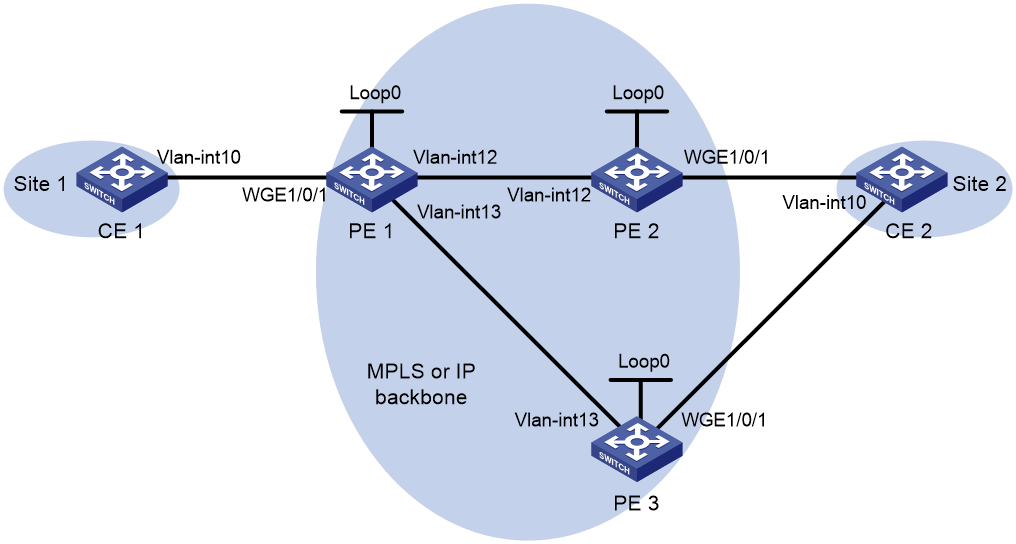
Table 3 Interface and IP address assignment
|
Device |
Interface |
IP address |
Device |
Interface |
IP address |
|
CE 1 |
Vlan-int10 |
100.1.1.1/24 |
PE 2 |
Loop0 |
2.2.2.2/32 |
|
PE 1 |
Loop0 |
1.1.1.1/32 |
|
Vlan-int12 |
12.1.1.2/24 |
|
|
Vlan-int12 |
12.1.1.1/24 |
PE 3 |
Loop0 |
3.3.3.3/32 |
|
|
Vlan-int13 |
13.1.1.1/24 |
|
Vlan-int13 |
13.1.1.3/24 |
|
CE 2 |
Vlan-int10 |
100.1.1.2/24 |
|
|
|
Prerequisites
Before you configure BFD for PW, perform the following tasks on the switches:
· Create VLANs and add ports to the VLANs.
· Disable the spanning tree feature globally or map each VLAN to an MSTI. For more information, see Layer 2—LAN Switching Configuration Guide.
Procedure
1. Configure CE 1.
<CE1> system-view
[CE1] interface vlan-interface 10
[CE1-Vlan-interface10] ip address 100.1.1.1 24
[CE1-Vlan-interface10] quit
2. Configure PE 1:
# Configure an LSR ID.
<PE1> system-view
[PE1] interface loopback 0
[PE1-LoopBack0] ip address 1.1.1.1 32
[PE1-LoopBack0] quit
[PE1] mpls lsr-id 1.1.1.1
# Enable global MPLS LDP.
[PE1] mpls ldp
[PE1-ldp] quit
# Establish LDP sessions with PE 2 and PE 3.
[PE1] interface vlan-interface 12
[PE1-Vlan-interface12] ip address 12.1.1.1 24
[PE1-Vlan-interface12] mpls enable
[PE1-Vlan-interface12] mpls ldp enable
[PE1-Vlan-interface12] quit
[PE1] interface vlan-interface 13
[PE1-Vlan-interface13] ip address 13.1.1.1 24
[PE1-Vlan-interface13] mpls enable
[PE1-Vlan-interface13] mpls ldp enable
[PE1-Vlan-interface13] quit
# Configure OSPF for LDP to create LSPs.
[PE1] ospf
[PE1-ospf-1] area 0
[PE1-ospf-1-area-0.0.0.0] network 1.1.1.1 0.0.0.0
[PE1-ospf-1-area-0.0.0.0] network 12.1.1.0 0.0.0.255
[PE1-ospf-1-area-0.0.0.0] network 13.1.1.0 0.0.0.255
[PE1-ospf-1-area-0.0.0.0] quit
[PE1-ospf-1] quit
# Enable L2VPN.
[PE1] l2vpn enable
# Enable BFD for MPLS.
[PE1] mpls bfd enable
# Create an Ethernet service instance on Twenty-FiveGigE 1/0/1 (the interface connected to CE 1).
[PE1] interface twenty-fivegige 1/0/1
[PE1-Twenty-FiveGigE1/0/1] service-instance 10
[PE1-Twenty-FiveGigE1/0/1-srv1000] encapsulation s-vid 10
[PE1-Twenty-FiveGigE1/0/1-srv1000] quit
[PE1-Twenty-FiveGigE1/0/1] quit
# Create PW class pwa. In the PW class, configure BFD to verify PW connectivity and configure the VCCV CC type as router-alert.
[PE1] pw-class pwa
[PE1-pw-pwa] vccv bfd
[PE1-pw-pwa] vccv cc router-alert
[PE1-pw-pwa] quit
# Create cross-connect group vpna and create cross-connect ldp in the cross-connect group. Bind the cross-connect to Ethernet service instance 10 on Twenty-FiveGigE 1/0/1 and create the primary and backup LDP PWs in the cross-connect. The primary PW uses PW class pwa.
[PE1] xconnect-group vpna
[PE1-xcg-vpna] connection ldp
[PE1-xcg-vpna-ldp] ac interface twenty-fivegige 1/0/1 service-instance 10
[PE1-xcg-vpna-ldp] peer 2.2.2.2 pw-id 20 pw-class pwa
[PE1-xcg-vpna-ldp-2.2.2.2-20] backup-peer 3.3.3.3 pw-id 30
[PE1-xcg-vpna-ldp-3.3.3.3-20-backup] quit
[PE1-xcg-vpna-ldp-2.2.2.2-20] quit
[PE1-xcg-vpna-ldp] quit
[PE1-xcg-vpna] quit
[PE1] quit
3. Configure PE 2:
# Configure an LSR ID.
<PE2> system-view
[PE2] interface loopback 0
[PE2-LoopBack0] ip address 2.2.2.2 32
[PE2-LoopBack0] quit
[PE2] mpls lsr-id 2.2.2.2
# Enable global MPLS LDP.
[PE2] mpls ldp
[PE2-ldp] quit
# Establish an LDP session to PE 1.
[PE2] interface vlan-interface 12
[PE2-Vlan-interface12] ip address 12.1.1.2 24
[PE2-Vlan-interface12] mpls enable
[PE2-Vlan-interface12] mpls ldp enable
[PE2-Vlan-interface12] quit
# Configure OSPF for LDP to create LSPs.
[PE2] ospf
[PE2-ospf-1] area 0
[PE2-ospf-1-area-0.0.0.0] network 12.1.1.0 0.0.0.255
[PE2-ospf-1-area-0.0.0.0] network 2.2.2.2 0.0.0.0
[PE2-ospf-1-area-0.0.0.0] quit
[PE2-ospf-1] quit
# Enable L2VPN.
[PE2] l2vpn enable
# Enable BFD for MPLS.
[PE2] mpls bfd enable
# Create an Ethernet service instance on Twenty-FiveGigE 1/0/1 (the interface connected to CE 2).
[PE2] interface twenty-fivegige 1/0/1
[PE2-Twenty-FiveGigE1/0/1] service-instance 10
[PE2-Twenty-FiveGigE1/0/1-srv1000] encapsulation s-vid 10
[PE2-Twenty-FiveGigE1/0/1-srv1000] quit
[PE2-Twenty-FiveGigE1/0/1] quit
# Create PW class pwa. In the PW class, configure BFD to verify PW connectivity and configure the VCCV CC type as router-alert.
[PE2] pw-class pwa
[PE2-pw-pwa] vccv bfd
[PE2-pw-pwa] vccv cc router-alert
[PE2-pw-pwa] quit
# Create cross-connect group vpna and create cross-connect ldp in the cross-connect group. Bind the cross-connect to Ethernet service instance 10 on Twenty-FiveGigE 1/0/1 and create an LDP PW that uses PW class pwa in the cross-connect.
[PE2] xconnect-group vpna
[PE2-xcg-vpna] connection ldp
[PE2-xcg-vpna-ldp] ac interface twenty-fivegige 1/0/1 service-instance 10
[PE2-xcg-vpna-ldp] peer 1.1.1.1 pw-id 20 pw-class pwa
[PE2-xcg-vpna-ldp-1.1.1.1-20] quit
[PE2-xcg-vpna-ldp] quit
[PE2-xcg-vpna] quit
4. Configure PE 3:
# Configure an LSR ID.
<PE3> system-view
[PE3] interface loopback 0
[PE3-LoopBack0] ip address 3.3.3.3 32
[PE3-LoopBack0] quit
[PE3] mpls lsr-id 3.3.3.3
# Enable global MPLS LDP.
[PE3] mpls ldp
[PE3-ldp] quit
# Establish an LDP session to PE 1.
[PE3] interface vlan-interface 13
[PE3-Vlan-interface13] ip address 13.1.1.3 24
[PE3-Vlan-interface13] mpls enable
[PE3-Vlan-interface13] mpls ldp enable
[PE3-Vlan-interface13] quit
# Configure OSPF for LDP to create LSPs.
[PE3] ospf
[PE3-ospf-1] area 0
[PE3-ospf-1-area-0.0.0.0] network 13.1.1.0 0.0.0.255
[PE3-ospf-1-area-0.0.0.0] network 3.3.3.3 0.0.0.0
[PE3-ospf-1-area-0.0.0.0] quit
[PE3-ospf-1] quit
# Enable L2VPN.
[PE3] l2vpn enable
# Create an Ethernet service instance on Twenty-FiveGigE 1/0/1 (the interface connected to CE 2).
[PE3] interface twenty-fivegige 1/0/1
[PE3-Twenty-FiveGigE1/0/1] service-instance 10
[PE3-Twenty-FiveGigE1/0/1-srv1000] encapsulation s-vid 10
[PE3-Twenty-FiveGigE1/0/1-srv1000] quit
[PE3-Twenty-FiveGigE1/0/1] quit
# Create cross-connect group vpna and create cross-connect ldp in the cross-connect group. Bind the cross-connect to Ethernet service instance 10 on Twenty-FiveGigE 1/0/1 and create an LDP PW in the cross-connect.
[PE3] xconnect-group vpna
[PE3-xcg-vpna] connection ldp
[PE3-xcg-vpna-ldp] ac interface twenty-fivegige 1/0/1 service-instance 10
[PE3-xcg-vpna-ldp] peer 1.1.1.1 pw-id 30
[PE3-xcg-vpna-ldp-1.1.1.1-30] quit
[PE3-xcg-vpna-ldp] quit
[PE3-xcg-vpna] quit
5. Configure CE 2.
<CE2> system-view
[CE2] interface vlan-interface 10
[CE2-Vlan-interface10] ip address 100.1.1.2 24
[CE2-Vlan-interface10] quit
Verifying the configuration
# Display L2VPN PW information on PE 1. The output shows that two PWs (one primary and one backup) have been established.
<PE1> display l2vpn pw
Flags: M - main, B - backup, H - hub link, S - spoke link, N - no split horizon
Total number of PWs: 2, 1 up, 1 blocked, 0 down, 0 defect
Xconnect-group Name: vpna
Peer PW ID In/Out Label Proto Flag Link ID State
2.2.2.2 20 1151/1279 LDP M 1 Up
3.3.3.3 30 1150/1279 LDP B 1 Blocked
# Display L2VPN PW information on PE 2. The output shows that a PW has been established.
[PE2] display l2vpn pw
Flags: M - main, B - backup, H - hub link, S - spoke link, N - no split horizon
Total number of PWs: 1, 1 up, 0 blocked, 0 down, 0 defect
Xconnect-group Name: vpna
Peer PW ID In/Out Label Proto Flag Link ID State
1.1.1.1 20 1279/1151 LDP M 1 Up
# Display L2VPN PW information on PE 3. The output shows that a PW has been established.
[PE3] display l2vpn pw
Flags: M - main, B - backup, H - hub link, S - spoke link, N - no split horizon
Total number of PWs: 1, 1 up, 0 blocked, 0 down, 0 defect
Xconnect-group Name: vpna
Peer PW ID In/Out Label Proto Flag Link ID State
1.1.1.1 30 1279/1150 LDP M 1 Up
# Execute the display l2vpn pw bfd command on PE 1 and PE 2. The output shows that a BFD session in up state has been established between PE 1 and PE 2. The BFD session verifies the PW connectivity between 1.1.1.1/32 and 2.2.2.2/32. This example uses PE 1.
[PE1] display l2vpn pw bfd
Total number of sessions: 1, 1 up, 0 down, 0 init
FEC Type: PW FEC-128
FEC Info:
Peer IP: 2.2.2.2
PW ID: 20
Connection ID: 2147483648 Link ID: 1
Local Discr: 514 Remote Discr: 514
Source IP: 1.1.1.1 Destination IP: 127.0.0.2
Session State: Up Session Role: Active
Template Name: -
# Verify that CE 1 and CE 2 can ping each other. (Details not shown.)
# Shut down the PW between PE 1 and PE 2. Execute the display l2vpn pw bfd command. The output shows that the BFD session goes down.
[PE1] display l2vpn pw bfd
Total number of sessions: 1, 0 up, 1 down, 0 init
FEC Type: PW FEC-128
FEC Info:
Peer IP: 2.2.2.2
PW ID: 20
Connection ID: 2147483648 Link ID: 1
Local Discr: 514 Remote Discr: 514
Source IP: 1.1.1.1 Destination IP: 127.0.0.2
Session State: Down Session Role: Active
Template Name: -
# Display L2VPN PW information on PE 1. The output shows that backup PW is in use.
<PE1> display l2vpn pw
Flags: M - main, B - backup, H - hub link, S - spoke link, N - no split horizon
Total number of PWs: 2, 1 up, 0 blocked, 0 down, 1 defect
Xconnect-group Name: vpna
Peer PW ID In/Out Label Proto Flag Link ID State
2.2.2.2 20 1151/1279 LDP M 1 BFD Defect
3.3.3.3 30 1150/1279 LDP B 1 Up
# Verify that CE 1 and CE 2 can ping each other. (Details not shown.)