- Table of Contents
-
- 07-MPLS Configuration Guide
- 00-Preface
- 01-Basic MPLS configuration
- 02-SR-MPLS configuration
- 03-Static LSP configuration
- 04-LDP configuration
- 05-MPLS TE configuration
- 06-Static CRLSP configuration
- 07-RSVP configuration
- 08-Tunnel policy configuration
- 09-MPLS L3VPN configuration
- 10-MPLS L2VPN configuration
- 11-VPLS configuration
- 12-MPLS OAM configuration
- 13-MCE configuration
- Related Documents
-
| Title | Size | Download |
|---|---|---|
| 02-SR-MPLS configuration | 223.62 KB |
Restrictions and guidelines: SR-MPLS configuration
IP traffic forwarding over SRLSPs tasks at a glance
MPLS TE traffic forwarding over static SRLSPs tasks at a glance
Prerequisites for static segment configuration
Configuring a static adjacency segment
Configuring a static prefix segment
Configuring an MPLS TE tunnel to use static SRLSPs
Display and maintenance commands for SR-MPLS
SR-MPLS configuration examples
Example: Configuring SR-MPLS based on static segments
Configuring SR-MPLS
About SR-MPLS
Segment Routing (SR) is a source routing technology. The source node selects a path for the packets, and then encodes the path in the packet header as an ordered list of segments. Each segment is identified by the segment identifier (SID). The SR nodes along the path forward the packets based on the SIDs in the packets. Only the source node needs to maintain the path status.
SR can operate with MPLS. In an MPLS network, SR uses MPLS labels as SIDs to forward packets on an LSP.
SR-MPLS characteristics
SR-MPLS has the following characteristics:
· SR-MPLS forwards packets based on the existing MPLS infrastructure. No infrastructure modifications are needed to implement SR on an MPLS network. For more information about the MPLS infrastructure, see MPLS basics configuration in MPLS Configuration Guide.
· SR-MPLS implements network features such as MPLS TE in a simpler way, eliminating issues such as heavy and complicated routing protocol deployment.
Basic concepts
· SR node—A node enabled with the SR-MPLS feature. The ingress node (source node) adds labels to packets. The transit nodes forward packets based on labels. The egress node removes labels and forwards packets to the destination networks. SR nodes form an SR domain.
· Segment—An instruction an SR node executes on the incoming packet.
· SID—Segment ID, which is MPLS label in SR-MPLS.
· Segment type—The following types of segments are available:
¡ Prefix segment—SIDs are assigned to nodes based on destination address prefix. The nodes create prefix-specific forwarding entries.
¡ Adjacency segment—SIDs are assigned to nodes based on adjacency.
· SRLSP—Segment routing label switched path, an LSP along which SR uses MPLS labels as SIDs to forward packets.
How SR-MPLS works
SR-MPLS involves the following steps:
1. Label allocation for all nodes and links along the packet forwarding paths.
2. Label forwarding entry installation based on SIDs. All SR-MPLS devices in the SR domain use the allocated labels to create label forwarding entries.
3. SRLSP setup.
When the ingress node of an SRLSP receives a packet, it adds labels to the packet and forwards the packet to the egress node through the SRLSP. After receiving a packet from the SRLSP, the egress node removes the label and forwards the packet based on the routing table.
You can bind a higher layer application (for example, MPLS TE) to an SRLSP to forward traffic of the application through the SRLSP.
Static segment configuration
Static SR-MPLS provides the following methods for configuring static segments for a destination:
· Prefix segment method—Manually configure the incoming label, outgoing label, and next hop for the destination address prefix on each SR node.
· Adjacency segment method—Manually configure the incoming label and next hop for the adjacency to the neighbor on each SR node.
SRLSP setup
You can manually configure an SRLSP. To configure an SRLSP, you must specify the label stack for packets to be forwarded along the SRLSP on the ingress node. Each label in the stack corresponds to a prefix SID or adjacency SID. The system can look for the outgoing label and next hop based on the prefix SID or adjacency SID.
Packet forwarding in SR-MPLS
Based on the SID allocation method, SR-MPLS uses one of the following packet forwarding methods:
· Prefix SID-based packet forwarding—The ingress node encapsulates the prefix SID for the egress node to a packet. The transit nodes forward the packet based on label forwarding entries.
· Adjacency SID-based packet forwarding—The ingress node encapsulates the label stack that contains the adjacency SIDs of all links along the forwarding path to a packet. Each transit node uses the top label in the label stack to determine the next hop and pops the top label before forwarding the packet to the next hop.
· Prefix and adjacency SID-based packet forwarding—The nodes use prefix SID-based packet forwarding in combination with adjacency-based packet forwarding.
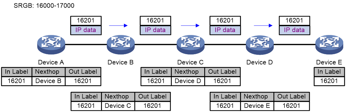
Prefix SID-based packet forwarding within the same AS
Figure 1 shows how a packet is forwarded along the SRLSP from Device A to Device E based on prefix SIDs. In this example, the outgoing label for the packet is 16201 on Device A.
1. Ingress node Device A searches for a forwarding entry for label 16201, adds outgoing label 16201 to the packet and sends the packet to the next hop (Device B).
2. When transit node Device B receives the packet, it searches for a label forwarding entry that matches the label in the packet. Then, Device B uses the outgoing label of the matched entry (16201) to replace the label in the packet and forwards the packet to the next hop (Device C).
3. Transit nodes Device C and Device D process the packet in the same way Device B does.
4. When egress node Device E receives the packet, it removes the label and forwards the packet by IP address.
Figure 1 Prefix SID-based packet forwarding within the same AS
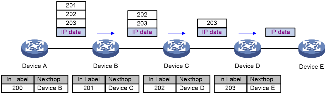
Adjacency SID-based packet forwarding
Figure 2 shows how a packet is forwarded along the SRLSP from Device A to Device E based on adjacency SIDs. In this example, the label stack for the packet is configured as (200, 201, 202, and 203) on Device A.
1. Ingress node Device A searches for a forwarding entry for the top label (200) to determine the next hop. Then, Device A adds label stack (201, 202, and 203) to the packet, and forwards the packet to the next hop (Device B).
2. When transit node Device B receives the packet, it searches for a forwarding entry for the top label (201) to determine the next hop. Then, Device B removes the top label from the stack and forwards the packet to the next hop (Device C).
3. When transit node Device C receives the packet, it searches for a forwarding entry for the top label (202) to determine the next hop. Then, Device C removes the top label from the stack and forwards the packet to the next hop (Device D).
4. When transit node Device D receives the packet, it searches for a forwarding entry for the label (203) to determine the next hop. Then, Device D removes the label stack from the packet and forwards the packet to the next hop (Device E).
5. When egress node Device E receives the packet, it forwards the packet by IP address.
Figure 2 Adjacency SID-based packet forwarding
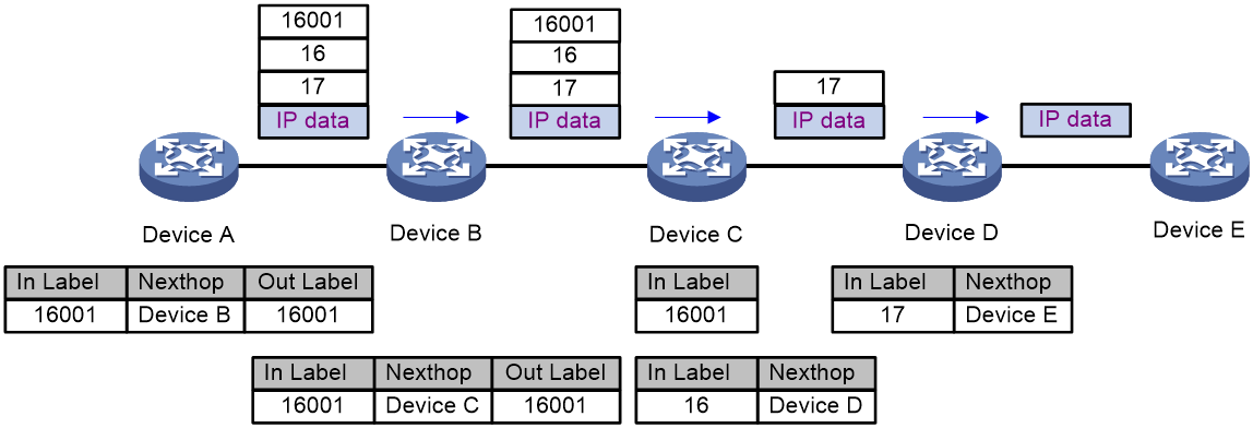
Prefix and adjacency SID-based packet forwarding
Figure 3 shows how a packet is forwarded along the SRLSP from Device A to Device E based on prefix SIDs and adjacency SIDs. In this example, the index value for the prefix SID of Device C is 1. The prefix SIDs for Device A, Device B, and Device C are all 16001. The Adjacency SIDs that Device C and Device D allocate to the adjacencies are 16 and 17, respectively. On Device A, the label stack for the packet is (16001, 16, 17).
1. Ingress node Device A searches for a forwarding entry for label 16001 to determine the outgoing label (16001) and next hop (Device B). Device adds label stack (16001, 16, 17) to the packet and sends the packet to the next hop (Device B).
2. When transit node Device B receives the packet, it searches for a label forwarding entry that matches the top label in the label stack (16001). Then, Device B uses the outgoing label of the matched entry (16001) to replace the top label and forwards the packet to the next hop (Device C).
3. When transit node Device C receives the packet, it removes the top label 16001 and searches for a forwarding entry for the next label (16) to determine the next hop. Then, Device C removes label 16 from the stack and forwards the packet to the next hop (Device D).
4. When transit node Device D receives the packet, it searches for a forwarding entry for the label (17) to determine the next hop. Then, Device D removes the label stack from the packet and forwards the packet to the next hop (Device E).
5. When egress node Device E receives the packet, it forwards the packet by IP address.
Figure 3 Prefix and adjacency SID-based packet forwarding
Restrictions and guidelines: SR-MPLS configuration
If you have configured MPLS features, do not configure FCoE. Otherwise, FCoE might not be able to take effect.
SR-MPLS tasks at a glance
IP traffic forwarding over SRLSPs tasks at a glance
To forward IP traffic over SRLSPs, perform the following configuration tasks:
1. Configuring segments
MPLS TE traffic forwarding over static SRLSPs tasks at a glance
To forward MPLS TE traffic over static SRLSPs, perform the following configuration tasks:
1. Configuring segments
2. Configuring an MPLS TE tunnel to use static SRLSPs
Configuring static segments
Prerequisites for static segment configuration
Before you configure static segments for a static SRLSP, perform the following tasks:
· Determine the ingress node, transit nodes, and egress node of the static SRLSP.
· Determine the incoming label for the adjacency segment from a node to next hop of the node. Determine the incoming label of the prefix segment for the destination IP address on each node. On a device, a static SRLSP, a static LSP, and a static CRLSP cannot use the same incoming label. For more information about CRLSP, see MPLS TE configuration in MPLS Configuration Guide.
· Enable MPLS on all nodes and interfaces that will participate in MPLS forwarding. For information about enabling MPLS, see basic MPLS configuration in MPLS Configuration Guide.
Configuring a static adjacency segment
Restrictions and guidelines
This task is required on all nodes of a static SRLSP.
Multiple static SRLSPs can share an adjacency segment.
If you specify the next hop address for a static adjacency segment, make sure the following requirements are met:
· The device has a route to the next hop address.
· MPLS is enabled on the outgoing interface of the route.
If you specify an outgoing interface for a static adjacency segment, make sure the following requirements are met:
· The interface is up.
· The interface can receive direct routes.
· MPLS is enabled on the interface.
A static adjacency segment must use a different incoming label than existing static LSPs, static PWs, and static CRLSPs. If not, the configured adjacency segment is unavailable. The adjacency segment cannot become available even if you change the incoming label of the static LSP, static PW, or static CRLSP. To resolve this problem, you must delete the existing adjacency segment and configure a new one with a different incoming label.
Procedure
1. Enter system view.
system-view
2. Configure a static adjacency segment.
static-sr-mpls adjacency adjacency-path-name in-label label-value { nexthop ip-address | outgoing-interface interface-type interface-number }
The next hop address for a static adjacency segment cannot be a local public IP address.
Configuring a static prefix segment
Restrictions and guidelines
This task is required on all nodes of a static SRLSP.
Multiple static SRLSPs to the same destination can share a prefix segment.
A prefix segment must use the next hop or outgoing interface of the optimal route (non-BGP route) to the destination address of the prefix segment. You can configure multiple prefix segments to the destination address for load sharing if the optimal route has more than one next hop or outgoing interface. To avoid configuration failure, make sure all prefix segments use the same prefix segment name and incoming label.
Procedure
1. Enter system view.
system-view
2. Configure a static prefix segment.
static-sr-mpls prefix prefix-path-name destination ip-address { mask-length | mask } in-label in-label-value [ { nexthop ip-address | outgoing-interface interface-type interface-number } out-label out-label-value ]
The next hop address for a static prefix segment cannot be a local public IP address.
Configuring an MPLS TE tunnel to use static SRLSPs
Tasks at a glance
1. Enable MPLS TE.
Perform this task on all nodes that the MPLS TE tunnel traverses. For more information, see MPLS TE configuration in MPLS Configuration Guide.
Perform this task on the ingress node of the MPLS TE tunnel.
Configuring a static SRLSP
1. Enter system view.
system-view
2. Configure a static SRLSP.
static-sr-mpls lsp lsp-name out-label out-label-value&<1-8>
Display and maintenance commands for SR-MPLS
Execute display commands in any view.
|
Task |
Command |
|
Display static SRLSP and adjacency segment information. |
display mpls static-sr-mpls { lsp [ lsp-name ] | adjacency [ adjacency-path-name ] } |
|
Display static prefix segment information. |
display mpls static-sr-mpls prefix [ path lsp-name | destination ip-address [ mask | mask-length ] ] |
SR-MPLS configuration examples
Example: Configuring SR-MPLS based on static segments
Network configuration
As shown in Figure 4, Switch A, Switch B, Switch C, Switch D, and Switch E run IS-IS.
Establish an MPLS TE tunnel over a static SRLSP from Switch A to Switch D to transmit data between the two IP networks. The static SRLSP traverses three adjacency segments: Switch A—Switch B, Switch B—Switch C, and Switch C—Switch D.
Establish an MPLS TE tunnel over a static SRLSP from Switch A to Switch E to transmit data between the IP networks. The static SRLSP traverses three segments: Switch A—Switch B (adjacency segment), Switch B—Switch C (prefix segment), and Switch C—Switch E (adjacency segment).
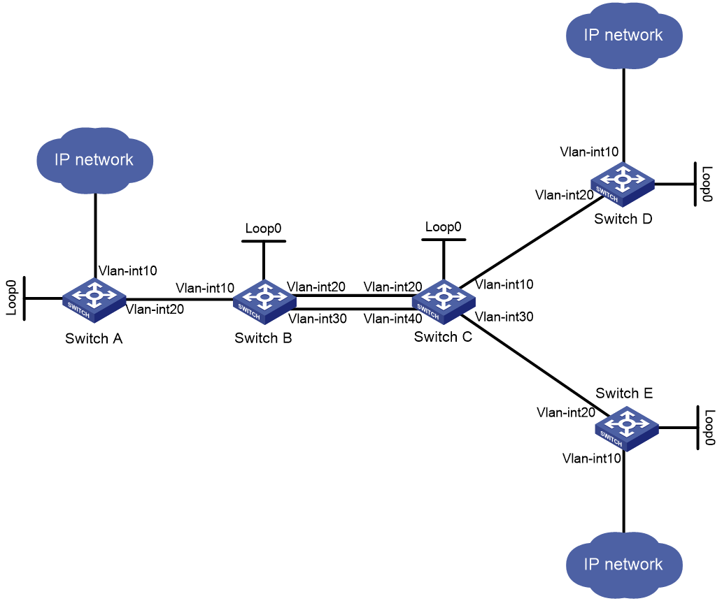
Table 1 Interface and IP address assignment
|
Device |
Interface |
IP address |
Device |
Interface |
IP address |
|
Switch A |
Loop0 |
1.1.1.9/32 |
Switch B |
Loop0 |
2.2.2.9/32 |
|
|
Vlan-int10 |
100.1.1.1/24 |
|
Vlan-int10 |
10.1.1.2/24 |
|
|
Vlan-int20 |
10.1.1.1/24 |
|
Vlan-int20 |
20.1.1.1/24 |
|
|
|
|
|
Vlan-int30 |
60.1.1.1/24 |
|
Switch C |
Loop0 |
3.3.3.9/32 |
Switch D |
Loop0 |
4.4.4.9/32 |
|
|
Vlan-int10 |
30.1.1.1/24 |
|
Vlan-int10 |
100.1.2.1/24 |
|
|
Vlan-int20 |
20.1.1.2/24 |
|
Vlan-int20 |
30.1.1.2/24 |
|
|
Vlan-int30 |
50.1.1.1/24 |
|
|
|
|
|
Vlan-int40 |
60.1.1.2/24 |
|
|
|
|
Switch E |
Loop0 |
5.5.5.9/32 |
|
|
|
|
|
Vlan-int10 |
200.1.2.1/24 |
|
|
|
|
|
Vlan-int20 |
50.1.1.2/24 |
|
|
|
Procedure
1. Configure IP addresses and masks for interfaces. (Details not shown.)
2. Configure IS-IS to advertise interface addresses, including the loopback interface addresses. (Details not shown.)
3. Execute the display ip routing-table command on each switch to verify that the switches have learned the routes to one another, including the routes to the loopback interfaces. (Details not shown.)
4. Configure LSR IDs, and enable MPLS and MPLS TE:
# Configure Switch A.
<SwitchA> system-view
[SwitchA] mpls lsr-id 1.1.1.9
[SwitchA] mpls te
[SwitchA-te] quit
[SwitchA] interface vlan-interface 20
[SwitchA-Vlan-interface20] mpls enable
[SwitchA-Vlan-interface20] quit
# Configure Switch B.
<SwitchB> system-view
[SwitchB] mpls lsr-id 2.2.2.9
[SwitchB] mpls te
[SwitchB-te] quit
[SwitchB] interface vlan-interface 10
[SwitchB-Vlan-interface10] mpls enable
[SwitchB-Vlan-interface10] quit
[SwitchB] interface vlan-interface 20
[SwitchB-Vlan-interface20] mpls enable
[SwitchB-Vlan-interface20] quit
[SwitchB] interface vlan-interface 30
[SwitchB-Vlan-interface30] mpls enable
[SwitchB-Vlan-interface30] quit
# Configure Switch C.
<SwitchC> system-view
[SwitchC] mpls lsr-id 3.3.3.9
[SwitchC] mpls te
[SwitchC-te] quit
[SwitchC] interface vlan-interface 10
[SwitchC-Vlan-interface10] mpls enable
[SwitchC-Vlan-interface10] quit
[SwitchC] interface vlan-interface 20
[SwitchC-Vlan-interface20] mpls enable
[SwitchC-Vlan-interface20] quit
[SwitchC] interface vlan-interface 30
[SwitchC-Vlan-interface30] mpls enable
[SwitchC-Vlan-interface30] quit
[SwitchC] interface vlan-interface 40
[SwitchC-Vlan-interface40] mpls enable
[SwitchC-Vlan-interface40] quit
# Configure Switch D.
<SwitchD> system-view
[SwitchD] mpls lsr-id 4.4.4.9
[SwitchD] mpls te
[SwitchD-te] quit
[SwitchD] interface vlan-interface 20
[SwitchD-Vlan-interface20] mpls enable
[SwitchD-Vlan-interface20] quit
# Configure Switch E.
<SwitchE> system-view
[SwitchE] mpls lsr-id 5.5.5.9
[SwitchE] mpls te
[SwitchE-te] quit
[SwitchE] interface vlan-interface 20
[SwitchE-Vlan-interface20] mpls enable
[SwitchE-Vlan-interface20] quit
5. Configure adjacency segment labels on each node:
# On Switch A, create adjacency segment adjacency-1, and bind incoming label 16 to the next hop address 10.1.1.2.
[SwitchA] static-sr-mpls adjacency adjacency-1 in-label 16 nexthop 10.1.1.2
# On Switch B, create adjacency segment adjacency-2, and bind incoming label 21 to next hop address 20.1.1.2.
[SwitchB] static-sr-mpls adjacency adjacency-2 in-label 21 nexthop 20.1.1.2
# On Switch B, create prefix segments prefix-1 to destination IP address 5.5.5.9. Bind incoming label 16000 to next hop addresses 20.1.1.2 and 60.1.1.2, and specify outgoing label 16001.
[SwitchB] static-sr-mpls prefix prefix-1 destination 5.5.5.9 32 in-label 16000 nexthop 20.1.1.2 out-label 16001
[SwitchB] static-sr-mpls prefix prefix-1 destination 5.5.5.9 32 in-label 16000 nexthop 60.1.1.2 out-label 16001
# On Switch C, create adjacency segment adjacency-1, and bind incoming label 30 to next hop address 30.1.1.2. Create adjacency segment adjacency-2, and bind incoming label 31 to next hop address 50.1.1.2.
[SwitchC] static-sr-mpls adjacency adjacency-1 in-label 30 nexthop 30.1.1.2
[SwitchC] static-sr-mpls adjacency adjacency-2 in-label 31 nexthop 50.1.1.2
# On Switch C, create prefix segment prefix-1 to destination IP address 5.5.5.9, and specify incoming label 16001.
[SwitchC] static-sr-mpls prefix prefix-1 destination 5.5.5.9 32 in-label 16001
6. On Switch A, establish static SRLSP static-sr-lsp-1 to Switch D and static SRLSP static-sr-lsp-2 to Switch E:
# Configure Switch A as the ingress node of static SRLSP static-sr-lsp-1 and configure a label stack of [16, 21, 30].
[SwitchA] static-sr-mpls lsp static-sr-lsp-1 out-label 16 21 30
# Configure Switch A as the ingress node of static SRLSP static-sr-lsp-2 and configure a label stack of [16, 16000, 31].
[SwitchA] static-sr-mpls lsp static-sr-lsp-2 out-label 16 16000 31
7. Configure MPLS TE tunnels over static SRLSPs on Switch A:
# Establish static MPLS TE tunnel 1 to Switch D and specify the LSR ID of Switch D as the tunnel destination address. Bind static SRLSP static-sr-lsp-1 to MPLS TE tunnel interface 1.
[SwitchA] interface tunnel 1 mode mpls-te
[SwitchA-Tunnel1 ip address 6.1.1.1 255.255.255.0
[SwitchA-Tunnel1] destination 4.4.4.9
[SwitchA-Tunnel1] mpls te signaling static
[SwitchA-Tunnel1] mpls te static-sr-mpls static-sr-lsp-1
[SwitchA-Tunnel1] quit
# Establish static MPLS TE tunnel 2 to Switch E and specify the LSR ID of Switch E as the tunnel destination address. Bind static SRLSP static-sr-lsp-2 to MPLS TE tunnel interface 2.
[SwitchA] interface tunnel 2 mode mpls-te
[SwitchA-Tunnel2] ip address 7.1.1.1 255.255.255.0
[SwitchA-Tunnel2] destination 5.5.5.9
[SwitchA-Tunnel2] mpls te signaling static
[SwitchA-Tunnel2] mpls te static-sr-mpls static-sr-lsp-2
[SwitchA-Tunnel2] quit
8. On Switch A, configure two static routes to direct traffic destined for 100.1.2.0/24 and 200.1.2.0/24 to MPLS TE tunnel 1 and tunnel 2, respectively.
[SwitchA] ip route-static 100.1.2.0 24 tunnel 1 preference 1
[SwitchA] ip route-static 200.1.2.0 24 tunnel 2 preference 1
Verifying the configuration
# Display the MPLS TE tunnel information on Switch A.
[SwitchA] display mpls te tunnel-interface
Tunnel Name : Tunnel 1
Tunnel State : Up (Main CRLSP up)
Tunnel Attributes :
LSP ID : 1 Tunnel ID : 0
Admin State : Normal
Ingress LSR ID : 1.1.1.9 Egress LSR ID : 4.4.4.9
Signaling : Static Static CRLSP Name : -
Static SRLSP Name : static-sr-lsp-1/-
Resv Style : -
Tunnel mode : -
Reverse-LSP name : -
Reverse-LSP LSR ID : - Reverse-LSP Tunnel ID: -
Class Type : - Tunnel Bandwidth : -
Reserved Bandwidth : -
Setup Priority : 0 Holding Priority : 0
Affinity Attr/Mask : -/-
Explicit Path : -
Backup Explicit Path : -
Metric Type : TE
Record Route : - Record Label : -
FRR Flag : - Backup Bandwidth Flag: -
Backup Bandwidth Flag: - Backup Bandwidth Type: -
Backup Bandwidth : -
Bypass Tunnel : - Auto Created : -
Route Pinning : -
Retry Limit : 3 Retry Interval : 2 sec
Reoptimization : - Reoptimization Freq : -
Backup Type : - Backup LSP ID : -
Auto Bandwidth : - Auto Bandwidth Freq : -
Min Bandwidth : - Max Bandwidth : -
Collected Bandwidth : -
Tunnel Name : Tunnel 2
Tunnel State : Up (Main CRLSP up)
Tunnel Attributes :
LSP ID : 1 Tunnel ID : 1
Admin State : Normal
Ingress LSR ID : 1.1.1.9 Egress LSR ID : 5.5.5.9
Signaling : Static Static CRLSP Name : -
Static SRLSP Name : static-sr-lsp-2/-
Resv Style : -
Tunnel mode : -
Reverse-LSP name : -
Reverse-LSP LSR ID : - Reverse-LSP Tunnel ID: -
Class Type : - Tunnel Bandwidth : -
Reserved Bandwidth : -
Setup Priority : 0 Holding Priority : 0
Affinity Attr/Mask : -/-
Explicit Path : -
Backup Explicit Path : -
Metric Type : TE
Record Route : - Record Label : -
FRR Flag : - Bandwidth Protection : -
Backup Bandwidth Flag: - Backup Bandwidth Type: -
Backup Bandwidth : -
Bypass Tunnel : - Auto Created : -
Route Pinning : -
Retry Limit : 3 Retry Interval : 2 sec
Reoptimization : - Reoptimization Freq : -
Backup Type : - Backup LSP ID : -
Auto Bandwidth : - Auto Bandwidth Freq : -
Min Bandwidth : - Max Bandwidth : -
Collected Bandwidth : -
# Display static SRLSP establishment on each switch by using the display mpls lsp or display mpls static-sr-lsp command.
[SwitchA] display mpls lsp
FEC Proto In/Out Label Out Inter/NHLFE/LSINDEX
1.1.1.9/0/46565 StaticCR -/21 Vlan20
30
1.1.1.9/1/46565 StaticCR -/16000 Vlan20
31
- StaticCR 16/- Vlan20
10.1.1.2 Local -/- Vlan20
Tunnel0 Local -/- NHLFE1
Tunnel1 Local -/- NHLFE2
[SwitchB] display mpls lsp
FEC Proto In/Out Label Out Inter/NHLFE/LSINDEX
5.5.5.9/32 StaticCR 16000/16001 Vlan20
5.5.5.9/32 StaticCR 16000/16001 Vlan30
- StaticCR 21/- Vlan20
20.1.1.2 Local -/- Vlan20
60.1.1.2 Local -/- Vlan30
[SwitchC] display mpls lsp
FEC Proto In/Out Label Out Inter/NHLFE/LSINDEX
5.5.5.9/32 StaticCR 16001/- -
- StaticCR 30/- Vlan10
- StaticCR 31/- Vlan30
30.1.1.2 Local -/- Vlan10
50.1.1.2 Local -/- Vlan30
Network configuration
As shown in Figure 5, complete the following tasks:
· Start IS-IS and enable IS-IS-based SR-MPLS on the PEs in the same AS.
· Configure PE 1 and ASBR-PE 1 to exchange labeled IPv4 routes through IBGP. Enable BGP-based SR-MPLS.
· Configure PE 2 and ASBR-PE 2 to exchange labeled IPv4 routes through IBGP. Enable BGP-based SR-MPLS.
· Establish an MP-EBGP peer relationship between PE 1 and PE 2 to exchange VPNv4 routes.
· Configure ASBR-PE 1 and ASBR-PE 2 to exchange labeled IPv4 routes through EBGP. Enable BGP-based SR-MPLS.
· Configure dynamic SID allocation on loopback interfaces of the devices. Then, establish an SRLSP based on the allocated SIDs and configure an MPLS TE tunnel over the SRLSP to transmit data.
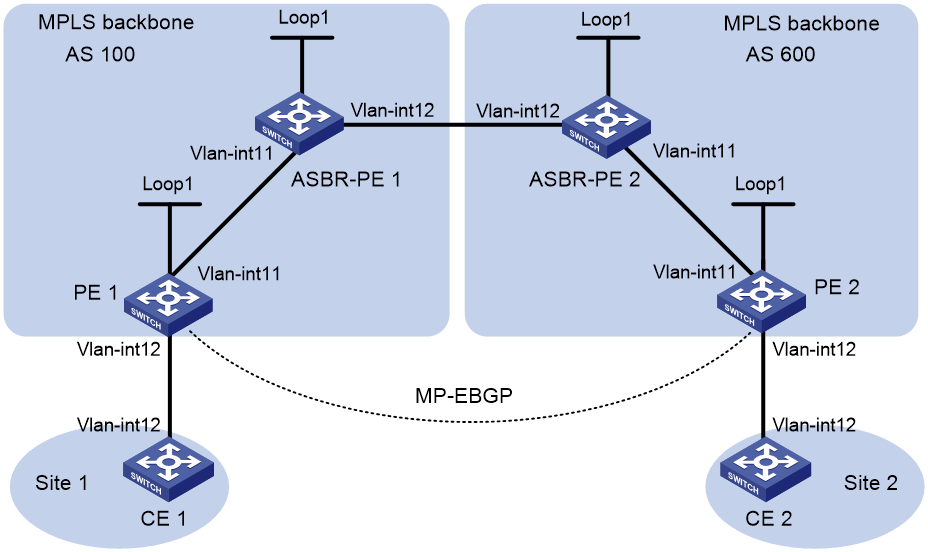
Table 2 Interface and IP address assignment
|
Device |
Interface |
IP address |
Device |
Interface |
IP address |
|
PE 1 |
Loop1 |
2.2.2.9/32 |
PE 2 |
Loop1 |
5.5.5.9/32 |
|
|
Vlan-int11 |
1.1.1.2/8 |
|
Vlan-int11 |
9.1.1.2/8 |
|
|
Vlan-int12 |
30.0.0.1/24 |
|
Vlan-int12 |
20.0.0.1/24 |
|
ASBR-PE 1 |
Loop1 |
3.3.3.9/32 |
ASBR-PE 2 |
Loop1 |
4.4.4.9/32 |
|
|
Vlan-int11 |
1.1.1.1/8 |
|
Vlan-int11 |
9.1.1.1/8 |
|
|
Vlan-int12 |
11.0.0.2/8 |
|
Vlan-int12 |
11.0.0.1/8 |
|
CE 1 |
Vlan-int12 |
30.0.0.2/24 |
CE 2 |
Vlan-int12 |
20.0.0.2/24 |
Procedure
1. Configure IP addresses and masks for interfaces. (Details not shown.)
2. Configure CE 1:
# Assign an IP address to interface VLAN-interface 12.
<CE1> system-view
[CE1] interface vlan-interface 12
[CE1-Vlan-interface12] ip address 30.0.0.2 24
[CE1-Vlan-interface12] quit
# Establish an EBGP peer relationship with PE 1, and redistribute VPN routes.
[CE1] bgp 65001
[CE1-bgp-default] peer 30.0.0.1 as-number 100
[CE1-bgp-default] address-family ipv4 unicast
[CE1-bgp-default-ipv4] peer 30.0.0.1 enable
[CE1-bgp-default-ipv4] import-route direct
3. Configure PE 1:
# Start IS-IS on PE 1, set the LSR ID, and enable MPLS and MPLS TE.
<PE1> system-view
[PE1] isis 1
[PE1-isis-1] network-entity 00.0000.0000.0001.00
[PE1-isis-1] cost-style wide
[PE1-isis-1] quit
[PE1] mpls lsr-id 2.2.2.9
[PE1] mpls te
[PE1-te] quit
[PE1] interface vlan-interface 11
[PE1-Vlan-interface11] isis enable 1
[PE1-Vlan-interface11] mpls enable
[PE1-Vlan-interface11] quit
[PE1] interface vlan-interface 12
[PE1-Vlan-interface12] mpls enable
[PE1-Vlan-interface12] quit
[PE1] interface loopback 1
[PE1-LoopBack1] ip address 2.2.2.9 32
[PE1-LoopBack1] isis enable 1
[PE1-LoopBack1] quit
# Enable SR-MPLS in IS-IS IPv4 unicast address family view and configure an IS-IS prefix SID.
[PE1] isis 1
[PE1-isis-1] address-family ipv4
[PE1-isis-1-ipv4] segment-routing mpls
[PE1-isis-1-ipv4] quit
[PE1-isis-1] quit
[PE1] interface loopback 1
[PE1-LoopBack1] isis prefix-sid index 20
[PE1-LoopBack1] quit
# Create VPN instance vpn1, and configure the RD and route target attributes.
[PE1] ip vpn-instance vpn1
[PE1-vpn-instance-vpn1] route-distinguisher 11:11
[PE1-vpn-instance-vpn1] vpn-target 1:1 2:2 3:3 import-extcommunity
[PE1-vpn-instance-vpn1] vpn-target 3:3 export-extcommunity
[PE1-vpn-instance-vpn1] quit
# Associate VLAN-interface 12 with VPN instance vpn1, and assign an IP address to the interface.
[PE1] interface vlan-interface 12
[PE1-Vlan-interface12] ip binding vpn-instance vpn1
[PE1-Vlan-interface12] ip address 30.0.0.1 24
[PE1-Vlan-interface12] quit
# Create a routing policy and specify a label index value.
[PE1] route-policy policy1 permit node 1
[PE1-route-policy-policy1-1] apply label-index 10
[PE1-route-policy-policy1-1] quit
# Start BGP on PE 1. Enable the capability to exchange labeled routes with IBGP peer 3.3.3.9.
[PE1] bgp 100
[PE1-bgp-default] peer 3.3.3.9 as-number 100
[PE1-bgp-default] peer 3.3.3.9 connect-interface loopback 1
[PE1-bgp-default] address-family ipv4 unicast
[PE1-bgp-default-ipv4] peer 3.3.3.9 enable
[PE1-bgp-default-ipv4] peer 3.3.3.9 label-route-capability
# Enable SR-MPLS.
[PE1-bgp-default-ipv4] segment-routing mpls
# Redistribute the route of loopback interface 1 to BGP and apply the routing policy.
[PE1-bgp-default-ipv4] network 2.2.2.9 32 route-policy policy1
[PE1-bgp-default-ipv4] quit
# Configure the maximum number of hops from PE 1 to EBGP peer 5.5.5.9 as 10.
[PE1-bgp-default] peer 5.5.5.9 as-number 600
[PE1-bgp-default] peer 5.5.5.9 connect-interface loopback 1
[PE1-bgp-default] peer 5.5.5.9 ebgp-max-hop 10
# Configure peer 5.5.5.9 as a VPNv4 peer.
[PE1-bgp-default] address-family vpnv4
[PE1-bgp-default-vpnv4] peer 5.5.5.9 enable
[PE1-bgp-default-vpnv4] quit
# Configure CE 1 as an EBGP peer of PE 1 and install the learned BGP routes in the routing table of the VPN instance.
[PE1-bgp-default] ip vpn-instance vpn1
[PE1-bgp-default-vpn1] peer 30.0.0.2 as-number 65001
[PE1-bgp-default-vpn1] address-family ipv4 unicast
[PE1-bgp-default-ipv4-vpn1] peer 30.0.0.2 enable
4. Configure ASBR-PE 1:
# Start IS-IS on ASBR-PE 1, set the LSR ID, and enable MPLS and MPLS TE.
<ASBR-PE1> system-view
[ASBR-PE1] isis 1
[ASBR-PE1-isis-1] network-entity 00.0000.0000.0002.00
[ASBR-PE1-isis-1] cost-style wide
[ASBR-PE1-isis-1] quit
[ASBR-PE1] mpls lsr-id 3.3.3.9
[ASBR-PE1] mpls te
[ASBR-PE1-te] quit
[ASBR-PE1] interface vlan-interface 11
[ASBR-PE1-Vlan-interface11] isis enable 1
[ASBR-PE1-Vlan-interface11] mpls enable
[ASBR-PE1-Vlan-interface11] quit
[ASBR-PE1] interface vlan-interface 12
[ASBR-PE1-Vlan-interface12] mpls enable
[ASBR-PE1-Vlan-interface12] quit
[ASBR-PE1] interface loopback 1
[ASBR-PE1-LoopBack1] ip address 3.3.3.9 32
[ASBR-PE1-LoopBack1] isis enable 1
[ASBR-PE1-LoopBack1] quit
# Enable SR-MPLS in IS-IS IPv4 unicast address family view and configure an IS-IS prefix SID.
[ASBR-PE1] isis 1
[ASBR-PE1-isis-1] address-family ipv4
[ASBR-PE1-isis-1-ipv4] segment-routing mpls
[ASBR-PE1-isis-1-ipv4] quit
[ASBR-PE1-isis-1] quit
[ASBR-PE1] interface loopback 1
[ASBR-PE1-LoopBack1] isis prefix-sid index 30
[ASBR-PE1-LoopBack1] quit
# Start BGP on ASBR-PE 1. Enable the capability to exchange labeled routes with IBGP peer 2.2.2.9.
[ASBR-PE1] bgp 100
[ASBR-PE1-bgp-default] peer 2.2.2.9 as-number 100
[ASBR-PE1-bgp-default] peer 2.2.2.9 connect-interface loopback 1
[ASBR-PE1-bgp-default] address-family ipv4 unicast
[ASBR-PE1-bgp-default-ipv4] peer 2.2.2.9 enable
[ASBR-PE1-bgp-default-ipv4] peer 2.2.2.9 label-route-capability
# Enable SR-MPLS.
[ASBR-PE1-bgp-default-ipv4] segment-routing mpls
[ASBR-PE1-bgp-default-ipv4] quit
# Enable the capability to exchange labeled routes with EBGP peer 11.0.0.1.
[ASBR-PE1-bgp-default] peer 11.0.0.1 as-number 600
[ASBR-PE1-bgp-default] address-family ipv4 unicast
[ASBR-PE1-bgp-default-ipv4] peer 11.0.0.1 enable
[ASBR-PE1-bgp-default-ipv4] peer 11.0.0.1 label-route-capability
[ASBR-PE1-bgp-default-ipv4] quit
[ASBR-PE1-bgp-default] quit
5. Configure ASBR-PE 2:
# Start IS-IS on ASBR-PE 2, set the LSR ID, and enable MPLS and MPLS TE.
<ASBR-PE2> system-view
[ASBR-PE2] isis 1
[ASBR-PE2-isis-1] network-entity 00.0000.0000.0003.00
[ASBR-PE2-isis-1] cost-style wide
[ASBR-PE2-isis-1] quit
[ASBR-PE2] mpls lsr-id 4.4.4.9
[ASBR-PE2] mpls te
[ASBR-PE2-te] quit
[ASBR-PE2] interface vlan-interface 11
[ASBR-PE2-Vlan-interface11] isis enable 1
[ASBR-PE2-Vlan-interface11] mpls enable
[ASBR-PE2-Vlan-interface11] quit
[ASBR-PE2] interface vlan-interface 12
[ASBR-PE2-Vlan-interface12] mpls enable
[ASBR-PE2-Vlan-interface12] quit
[ASBR-PE2] interface loopback 1
[ASBR-PE2-LoopBack1] ip address 4.4.4.9 32
[ASBR-PE2-LoopBack1] isis enable 1
[ASBR-PE2-LoopBack1] quit
# Enable SR-MPLS in IS-IS IPv4 unicast address family view and configure an IS-IS prefix SID.
[ASBR-PE2] isis 1
[ASBR-PE2-isis-1] address-family ipv4
[ASBR-PE2-isis-1-ipv4] segment-routing mpls
[ASBR-PE2-isis-1-ipv4] quit
[ASBR-PE2-isis-1] quit
[ASBR-PE2] interface loopback 1
[ASBR-PE2-LoopBack1] isis prefix-sid index 40
[ASBR-PE2-LoopBack1] quit
# Start BGP on ASBR-PE 2. Enable the capability to exchange labeled routes with IBGP peer 5.5.5.9.
[ASBR-PE2] bgp 600
[ASBR-PE2-bgp-default] peer 5.5.5.9 as-number 600
[ASBR-PE2-bgp-default] peer 5.5.5.9 connect-interface loopback 1
[ASBR-PE2-bgp-default] address-family ipv4 unicast
[ASBR-PE2-bgp-default-ipv4] peer 5.5.5.9 enable
[ASBR-PE2-bgp-default-ipv4] peer 5.5.5.9 label-route-capability
# Enable SR-MPLS.
[ASBR-PE2-bgp-default-ipv4] segment-routing mpls
[ASBR-PE2-bgp-default-ipv4] quit
# Enable the capability to exchange labeled routes with EBGP peer 11.0.0.2.
[ASBR-PE2-bgp-default] peer 11.0.0.2 as-number 100
[ASBR-PE2-bgp-default] address-family ipv4 unicast
[ASBR-PE2-bgp-default-ipv4] peer 11.0.0.2 enable
[ASBR-PE2-bgp-default-ipv4] peer 11.0.0.2 label-route-capability
[ASBR-PE2-bgp-default-ipv4] quit
[ASBR-PE2-bgp-default] quit
6. Configure PE 2:
# Start IS-IS on PE 2, set the LSR ID, and enable MPLS and MPLS TE.
<PE2> system-view
[PE2] isis 1
[PE2-isis-1] network-entity 00.0000.0000.0004.00
[PE2-isis-1] cost-style wide
[PE2-isis-1] quit
[PE2] mpls lsr-id 5.5.5.9
[PE2] mpls te
[PE2-te] quit
[PE2] interface vlan-interface 11
[PE2-Vlan-interface11] isis enable 1
[PE2-Vlan-interface11] mpls enable
[PE2-Vlan-interface11] quit
[PE2] interface vlan-interface 12
[PE2-Vlan-interface12] mpls enable
[PE2-Vlan-interface12] quit
[PE2] interface loopback 1
[PE2-LoopBack1] ip address 5.5.5.9 32
[PE2-LoopBack1] isis enable 1
[PE2-LoopBack1] quit
# Enable SR-MPLS in IS-IS IPv4 unicast address family view and configure an IS-IS prefix SID.
[PE2] isis 1
[PE2-isis-1] address-family ipv4
[PE2-isis-1-ipv4] segment-routing mpls
[PE2-isis-1-ipv4] quit
[PE2-isis-1] quit
[PE2] interface loopback 1
[PE2-LoopBack1] isis prefix-sid index 50
[PE2-LoopBack1] quit
# Create VPN instance vpn1, and configure the RD and route target attributes.
[PE2] ip vpn-instance vpn1
[PE2-vpn-instance-vpn1] route-distinguisher 11:11
[PE2-vpn-instance-vpn1] vpn-target 1:1 2:2 3:3 import-extcommunity
[PE2-vpn-instance-vpn1] vpn-target 3:3 export-extcommunity
[PE2-vpn-instance-vpn1] quit
# Associate VLAN-interface 12 with VPN instance vpn1, and assign an IP address to the interface.
[PE2] interface vlan-interface 12
[PE2-Vlan-interface12] ip binding vpn-instance vpn1
[PE2-Vlan-interface12] ip address 20.0.0.1 24
[PE2-Vlan-interface12] quit
# Create a routing policy and specify a label index value.
[PE2] route-policy policy1 permit node 1
[PE2-route-policy-policy1-1] apply label-index 50
[PE2-route-policy-policy1-1] quit
# Start BGP on PE 2. Enable the capability to exchange labeled routes with IBGP peer 4.4.4.9.
[PE2] bgp 600
[PE2-bgp-default] peer 4.4.4.9 as-number 600
[PE2-bgp-default] peer 4.4.4.9 connect-interface loopback 1
[PE2-bgp-default] address-family ipv4 unicast
[PE2-bgp-default-ipv4] peer 4.4.4.9 enable
[PE2-bgp-default-ipv4] peer 4.4.4.9 label-route-capability
# Enable SR-MPLS.
[PE2-bgp-default-ipv4] segment-routing mpls
# Redistribute the route of loopback interface 1 to BGP and apply the routing policy.
[PE2-bgp-default-ipv4] network 5.5.5.9 32 route-policy policy1
[PE2-bgp-default-ipv4] quit
# Configure the maximum number of hops from PE 2 to EBGP peer 2.2.2.9 as 10.
[PE2-bgp-default] peer 2.2.2.9 as-number 100
[PE2-bgp-default] peer 2.2.2.9 connect-interface loopback 1
[PE2-bgp-default] peer 2.2.2.9 ebgp-max-hop 10
# Configure peer 2.2.2.9 as a VPNv4 peer.
[PE2-bgp-default] address-family vpnv4
[PE2-bgp-default-vpnv4] peer 2.2.2.9 enable
[PE2-bgp-default-vpnv4] quit
# Configure CE 2 as an EBGP peer of PE 2 and install the learned BGP routes in the routing table of the VPN instance.
[PE2-bgp-default] ip vpn-instance vpn1
[PE2-bgp-default-vpn1] peer 20.0.0.2 as-number 65001
[PE2-bgp-default-vpn1] address-family ipv4 unicast
[PE2-bgp-default-ipv4-vpn1] peer 20.0.0.2 enable
7. Configure CE 2:
# Assign an IP address to interface VLAN-interface 12.
<CE2> system-view
[CE2] interface vlan-interface 12
[CE2-Vlan-interface12] ip address 20.0.0.2 24
[CE2-Vlan-interface12] quit
# Establish an EBGP peer relationship with PE 2, and redistribute VPN routes.
[CE2] bgp 65002
[CE2-bgp-default] peer 20.0.0.1 as-number 600
[CE2-bgp-default] address-family ipv4 unicast
[CE2-bgp-default-ipv4] peer 20.0.0.1 enable
[CE2-bgp-default-ipv4] import-route direct
[CE2-bgp-default-ipv4] quit
[CE2-bgp-default] quit
Verifying the configuration
# Execute the display ip routing-table command on CE 1 and CE 2 to verify that they have a route to each other. (Details not shown.)
# Verify that CE 1 and CE 2 can ping each other. (Details not shown.)
# Display MPLS LSP information on PE1.
[PE1]display mpls lsp
FEC Proto In/Out Label Out Inter/NHLFE/LSINDEX
2.2.2.9/32 BGP 3/- -
5.5.5.9/32 BGP -/16040 NHLFE17
5.5.5.9 BGP -/- Vlan11
1.1.1.1 Local -/- Vlan11
2.2.2.9/32 ISIS 16020/- -
3.3.3.9/32 ISIS 16030/3 Vlan11
3.3.3.9/32 ISIS -/3 Vlan11