- Table of Contents
- Related Documents
-
| Title | Size | Download |
|---|---|---|
| 01-Text | 3.67 MB |
Installation safety recommendations
Blade server chassis specifications
Chassis models and chassis view
Blade Server Installation Guidelines
AE module installation guidelines
LCD module installation guidelines
OM module installation guidelines
Interconnect module installation guidelines
Power supply installation guidelines
Fan module installation guidelines
Interconnect modules and blade servers
Installing the blade server chassis
Preparing the installation site
Space and Ventilation Requirements
Temperature and Humidity Requirements
Equipment Room Height Requirements
Installing cage nuts and slide rails
Installing the chassis on the adjustable slide rails
(Optional) Installing the cable management bracket
Connecting the PC to the chassis
Connecting the chassis to the network
Connecting power cords for the chassis
Connecting the blade server to the KVM device
Powering on and powering off the chassis
Default interconnect module parameters
Default blade server parameters
Configuring interconnect modules
Installing and Removing Blanks of All Modules
Replacing and using an LCD module
Replacing an interconnect module
Replacing the chassis midplane
Adding modules and components tto the chassis
Adding components to a blade server
Safety information
Power source recommendations
Power instability or outage might cause data loss, service disruption, or damage to the server in the worst case.
To protect the server from unstable power or power outage, use uninterrupted power supplies (UPSs) to provide power for the server.
Installation safety recommendations
To avoid personal injury or damage to the blade server chassis, read the following information carefully before you operate the blade server chassis. Safety precautions in actual operation include but are not limited to safety information mentioned in this document.
General operating safety
· Only H3C authorized or professional engineers are allowed to operate the blade server chassis.
· Place the blade server chassis on a clean, stable table or floor for servicing.
· Ensure that all cables are correctly connected before you power on the blade server chassis.
· Keep the blade server chassis clean and dust-free. Do not place it in a humid place or allow liquids to enter it.
· Gently and slowly transport or place the device with force evenly distributed.
· To avoid personal injury from hot surfaces, allow the blade server chassis and its internal modules to cool before touching them.
· Do not block air vents on the device to avoid damage to the device due to insufficient heat dissipation. When the blade server chassis and other devices are stacked on each other in the rack, reserve clearance of over 2 mm (0.09 in) in the vertical direction between two devices.
Electrical safety
· To avoid personal injury or damage to the device, always use the power cords that came with the blade server chassis.
· Do not use the power cords that came with the blade server chassis for any other devices.
· Power off the device when installing or removing any components that are not hot swappable.
· Carefully check any potential hazards in the work area, for example, whether the blade server chassis is grounded or reliably grounded, and whether the ground is wet.
· Do not work alone when performing live-line maintenance.
· The device supports multiple power inputs. When the device is powered off, check whether all power supplies are turned off.
· Connect power cords to different power distribution units (PDUs) in active/standby mode to ensure the reliability of the device.
· When installing the device, ensure that the ground cables are connected first and disconnected last. It is not allowed to damage the ground guide or operate the device without grounding. Check the grounding before operation. Note that the protective grounding conductors of the device installed in a rack must be connected to the grounding system of the blade server chassis, and the auxiliary ground cables must always be kept inside the rack system.
· Before operating the device, ensure that the device is permanently grounded and that the cross-sectional area of the ground cable is not less than 1.5 mm2 or 14 AWG.
Battery safety
The system board contains a system battery, which is designed with a lifespan of 5 to 10 years.
If the device no longer automatically displays the correct date and time, you need to replace the battery. When you replace the battery, follow these safety guidelines:
· Do not attempt to recharge the battery.
· Do not expose the battery to a temperature higher than 60°C (140°F).
· Do not disassemble, crush, puncture, short external contacts, or dispose of the battery in fire or water.
· Dispose of the battery at a designated facility. Do not throw the battery away together with other wastes.
Rack mounting recommendations
Rack safety recommendations
· Install the blade server chassis in a standard 19-inch rack.
· Ensure that the leveling jacks are extended to the floor and the full weight of the rack rests on the leveling jacks.
· Couple the racks together in multi-rack installations.
· Stabilize the rack when the extending or pushing the blade server chassis.
· For rack stability, ensure that only one unit is extended at a time. Otherwise, the rack might get unstable.
Installation safety recommendations
· Load the rack from the bottom to the top, with the heaviest hardware unit at the bottom of the rack. Install the devices from the bottom to the top, with the heaviest device installed first.
· When the device is loaded with modules, the handles that came with the device are only used to adjust the device position instead of lifting the device. Use tools such as forklift to lift the blade server chassis.
· When moving the device, hold the handles of the device or the bottom edge of the device instead of the handles of modules (such as Power supply, fan module, hard disk, or main board) installed in the device.
· Get help to lift and stabilize the blade server chassis during installation or removal, especially when the blade server chassis is not fastened to the slide rails. As a best practice, a minimum of four people are required to safely lift the blade server chassis. One more person might be required to help align the blade server chassis if the blade server chassis is installed higher than chest level.
· When using tools, follow the correct operation methods to avoid damage to the device.
· To maintain sufficient heat dissipation, install blanks in empty slots.
ESD prevention
Electrostatic charges that build up on people and conductors damage or shorten the lifespan of the main board and electrostatic-sensitive components.
Preventing electrostatic discharge
To prevent electrostatic damage, follow these guidelines:
· Transport or store the device with the components in ESD bags.
· Keep the electrostatic-sensitive components in the ESD bags until they arrive at an ESD-protected area.
· Place the components on a grounded table before taking them out of their ESD bags.
· Avoid touching pins, cables, or circuitry of the components without taking any ESD prevention measures.
· Ensure that you are reliably grounded when touching an electrostatic-sensitive component or assembly.
Grounding methods to prevent electrostatic discharge
The following are grounding methods that you can use to prevent electrostatic discharge:
· Wear an ESD wrist strap and make sure it makes good skin contact and is reliably grounded.
· Take adequate personal grounding measures, including wearing antistatic clothing and static dissipative shoes.
· Use conductive field service tools.
· Use a portable field service kit with a folding static-dissipating work mat.
Blade server chassis specifications
Hardware figures in this document are for illustration only.
Screenshots in this document are taken on a specific software version and are for illustration only.
The information in this document might differ from your product if it contains custom configuration options or features.
The model name of a hardware option in this document might differ slightly from its model name label. A model name label might add a prefix or suffix to the hardware-coded model name for purposes such as identifying the matching device brand or applicable region. For example, the RL-12U slide rail model represents slide rail labels including UIS-RL-12U-F, UIS-RL-12U, RL-12U-F, RL-12U, which have different prefixes and suffixes.
Chassis models and chassis view
H3C UniServer B16000 blade server chassis is a new generation of composable IT infrastructure that integrates computing, storage, switching, management, and multi-service support on a single platform. It is designed specifically for the data center, cloud computing, virtualization, and high-performance computing scenarios.
Figure 1 Blade server chassis

Technical specifications
|
Module |
Description |
|
Blade server |
Maximum number of supported blade servers: · Half-width and full-height blade server: 16 · Full-width and full-height blade server: 8 |
|
AE module |
A maximum of 2 |
|
LCD module |
A maximum of 1, sharing the same slot (E1) with the AE module |
|
OM module |
A maximum of 2 |
|
Interconnect module |
A maximum of 6 |
|
Fan module |
A maximum of 12, support for N+1 redundancy |
|
Power supply |
A maximum of 6 You can configure power supplies without redundancy, in N+1 redundancy, or in N+N redundancy as needed based on the requirements for service reliability and power supply mode in the equipment room. 3000 W platinum power supplies can be used for the chassis. |
Table 2 Technical Specifications
|
Item |
Description |
|
Dimensions (H × W × D) |
530 × 447 × 898 mm (20.87 × 17.60 × 35.35 in) |
|
Weight |
· Minimum weight: 64.50 kg (142.20 lb) · Maximum weight: 258.82 kg (570.59 lb) |
|
Temperature |
· Operating: 5°C to 45°C (41°F to 113°F) · Storage: –40°C to 70°C (–40°F to 158°F) |
|
Humidity |
· Operating: 8% to 90% (non-condensing) · Storage: 5% to 95% (non-condensing) |
|
Altitude |
· Operating: –60 m to +5000 m (–196.85 ft to +16404.20 ft). The allowed maximum temperature decreases by 0.33°C (32.59 °F) as the altitude increases by 100 m (328.08 ft) from 900 m (2952.76 ft). · Storage: –60 m to +5000 m (–196.85 ft to +16404.20 ft) |
Components
This section describes modules inside the blade server chassis.
Figure 2 Modules in the blade server chassis
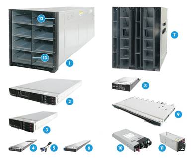
Table 3 Description for modules in the blade server chassis
|
Name |
|
|
1 |
Blade server chassis |
|
2 |
Blade server |
|
3 |
|
|
4 |
AE module |
|
5 |
SUV cable |
|
6 |
LCD module |
|
7 |
Midplane rear cage |
|
8 |
OM module |
|
9 |
Interconnect module |
|
10 |
Power supply |
|
11 |
Fan module |
|
12 |
Rack-mount ear cover plate |
|
13 |
Vertical divider |
Front and rear modules
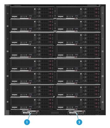
Front modules
Front modules
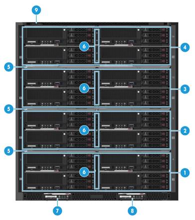
Table 4 Front modules
|
No. |
Description |
Remarks |
|
1 |
Blade server installation area 1 |
· The blade server chassis is partitioned into four areas by three non-detachable separators. · Each area has a detachable vertical separator used to separate slots in the area. · The maximum number of blade servers supported by each area is as follows (half-width and full-width blade servers cannot be installed in a mixed manner): ¡ Half-width and full-height blade server: 4 ¡ Full-width and full-height blade server: 2 |
|
2 |
Blade server installation area 2 |
|
|
3 |
Blade server installation area 3 |
|
|
4 |
Blade server installation area 4 |
|
|
5 |
Fixed divider (3 in total) |
|
|
6 |
Removable vertical divider (4 in total) |
|
|
7 |
E1 slot for AE or LCD module |
N/A |
|
8 |
E2 slot for AE module |
N/A |
|
9 |
Serial label pull tab |
N/A |
LEDs and buttons
For descriptions for the LEDs and buttons on the blade servers and AE modules, see the manual for the products.
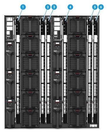
Rear modules
Rear modules
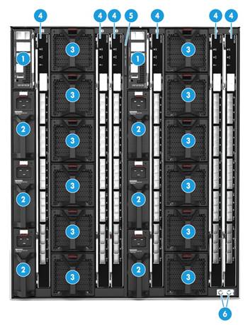
Table 5 Rear modules
|
No. |
Name |
|
1 |
OM module slots 1 and 2 |
|
2 |
Power supply slots 1 to 6 |
|
3 |
Fan module slots 1 to 12 |
|
4 |
Interconnect module slots 1 to 6 |
|
5 |
Serial label pull tab |
|
6 |
Ground terminal |
LEDs
· LEDs on the OM modules and interconnect modules
For the descriptions for the LEDs and buttons on the OM modules and interconnect modules, see the manual for the products.
· LED on the power supply
Figure 5 Power supply LED
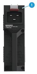
|
(1) Power supply LED |
Table 6 LED on a power supply
|
LED status |
Description |
|
Steady on green |
The power supply is operating correctly. |
|
Flashing green (1 Hz) |
Power is being input correctly to the power supply but the power supply is in sleep mode. |
|
Flashing green (2 Hz) |
The power supply is updating firmware. |
|
Steady orange |
· The power supply has no input, but other power supplies have correct power input.. · A failure has occurred on the power supply. ¡ Fan failure. ¡ Overcurrent protection. ¡ Overvoltage protection. |
|
Flashing orange (1 Hz) |
An alarm has occurred on the power supply, for example: · Overtemperature alarm. · Overvoltage alarm. · Overcurrent alarm. · Slow fan speed alarm. |
|
Off |
No power supplies have power input. |
· Fan module LED
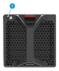
|
(1) Fan module LED |
|
Status |
Description |
|
Steady green |
The fan module is operating correctly. |
|
Steady red |
An alarm has occurred on the fan module: · Rotation blocked. · Communication failure with the OM module. · Overtemperature. |
|
Off |
The fan module has no power input. |
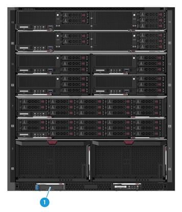
Installation Guidelines
Blade Server Installation Guidelines
|
|
CAUTION: Do not install a half-width blade server in an area where no vertical divider is installed. A forced installation might damage the blade server connector. |
As shown in Figure 7, the chassis is divided into four areas by three fixed dividers. Each area has one removable vertical divider which divides the slots in the area from full width to half width.
· In each area, you can install a maximum of four half-width and full-height blade servers or two full-width and full-height blade servers. Do not mix half-width and full-width blade servers in the same area.
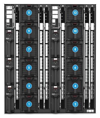
· As a best practice, install blade servers into the slots from left to right and bottom to top.
¡ Install half-width and full-height blade servers in the slot sequence of 1, 2, 3, 4, 5, 6, 7, 8, 9, 10, 11, 12, 13, 14, 15, and 16, as shown in Figure 8.
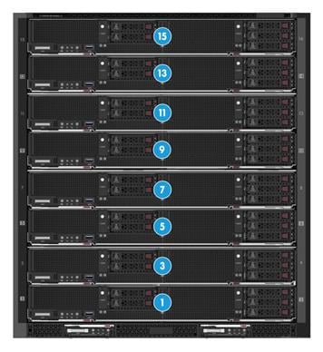
¡ Install full-width and full-height blade servers in the slot sequence of 1, 3, 5, 7, 9, 11, 13, and 15, as shown in Figure 9.
· To mix half-width and full-width blade servers on the same chassis, first install half-width blade servers from left to right and bottom to top and then install full-width blade server from bottom to top.
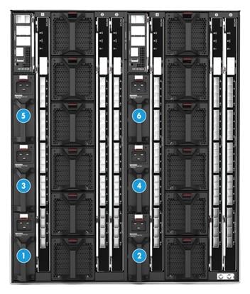
Figure 7 Four areas on the blade server front panel
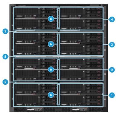
|
(1) Blade server installation area 1 |
(2) Blade server installation area 2 |
|
(3) Blade server installation area 3 |
(4) Blade server installation area 4 |
|
(5) Fixed divider (3 in total) |
(6) Removable vertical divider (4 in total) |
Figure 8 Installing sequence of half-width and full-height blade servers
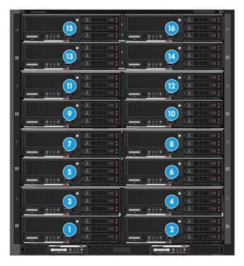
Figure 9 Installing sequence of full-width and full-height blade servers
AE module installation guidelines
Up to two AE modules can be installed in the blade server chassis. Figure 10 shows the installation positions for AE modules. No slot sequence must be followed for the installation.
Figure 10 AE module installation slots
|
(1) E1 slot |
(2) E2 slot |
LCD module installation guidelines
Only one LCD module can be installed in the blade server chassis. Figure 11 shows the installation position for the LCD module.
The LCD module is hot swappable.
Figure 11 LCD module installation slot
|
(1) E1 slot |
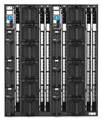
OM module installation guidelines
Up to two OM modules can be installed in the blade server chassis. Figure 12 shows the installation positions for OM modules. As a best practice, install the OM modules in the slot sequence of 1 and 2.
When two OM modules are installed, they operate in active/standby mode and you can hot swap one of them.
Figure 12 OM module installation guidelines
|
(1) OM1 slot |
(2) OM2 slot |
Interconnect module installation guidelines
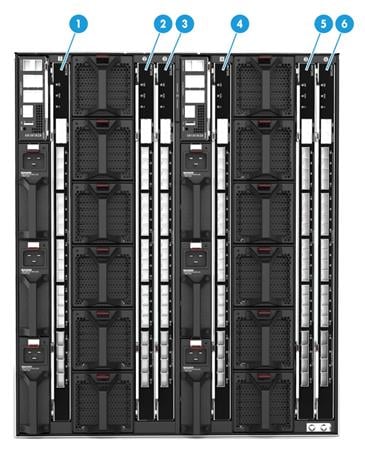
As shown in Figure 13, up to six interconnect modules can be installed in the blade server chassis.
When you select the installation positions for interconnect modules and Mezz network adapters, make sure they can be connected internally, as shown in Figure 18 and Figure 19.
The six interconnect module slots (ICM slot) can be divided into three connected pairs: slots 1 and 4, slots 2 and 5, and slots 3 and 6. The three pairs form three switching planes and the slots in each pair work in active/standby mode.
Interconnect modules are hot swappable.
Figure 13 Interconnect module installation slots
|
(1) ICM1 slot |
(2) ICM2 slot |
(3) ICM3 slot |
|
(4) ICM4 slot |
(5) ICM5 slot |
(6) ICM6 slot |
Power supply installation guidelines
As shown in Figure 14, up to six power supplies can be installed in the blade server chassis. The power supplies support no redundancy, N+1 redundancy, and N+N redundancy modes.
As a best practice, install power supplies from bottom to top and from left to right, in the sequence of 1, 2, 3, 4, 5, and 6.
The number of power supplies to be installed is related to the total power consumption of the blade server chassis. You can determine the number of power supplies required based on the total power consumption of the blade server chassis. Table 8 lists the maximum power of major modules of the blade server chassis. Table 9 to Table 13 describe the power supply configuration policies.
Make sure the models of all power supplies installed in the blade server chassis must be the same.
Do not use third-party power supplies. If third-party power supplies are used, hardware damage might occur.
In N+N redundancy mode, when power supplies are connected to external power sources, connect power supplies in slots 1, 3, and 5 to a power source, and those in slots 2, 4, and 6 to another power source.
The power supplies are hot swappable.
Figure 14 Power supply installation slots
|
(1) PSU1 slot |
(2) PSU2 slot |
(3) PSU3 slot |
|
(4) PSU4 slot |
(5) PSU5 slot |
(6) PSU6 slot |
Table 8 Max power consumption of the modules in the chassis
|
Module type |
Module model |
Max power consumption |
|
Blade server |
H3C UniServer B5700 G3 |
750 W |
|
H3C UniServer B5800 G3 |
900 W |
|
|
H3C UniServer B7800 G3 |
1400 W |
|
|
AE module |
H3C UniSever AE100 |
60 W |
|
LCD module |
SID-LCD-B |
5 W |
|
OM module |
H3C UniSever OM100 |
30 W |
|
Interconnect module |
H3C UniServer BX720E |
90 W |
|
H3C UniServer BX720EF |
110 W |
|
|
H3C UniServer BX608FE |
95 W |
|
|
Fan module |
FAN-L-B |
80 W |
|
Note: The table shows the maximum power consumption of modules in the chassis. The actual power consumption of each module depends on its configuration (such as the number of processors and drives configured on it). |
||
3000W power supply configuration policies
Table 9 shows the configuration policy for 3000W power supplies at an input voltage of 90 to 180 VAC @ 50/60 Hz and output power of 1200 W.
Table 9 Power supply configuration policy (1)
|
Power range |
Redundancy mode |
Power supply quantity |
Power supply installation position |
|
P < 1200 W |
No redundancy |
1 |
PSU1 |
|
1200 W < P < 2400 W |
No redundancy |
2 |
PSU1 and PSU2 |
|
2400 W < P < 3600 W |
No redundancy |
3 |
PSU1, PSU2, and PSU3 |
|
3600 W < P < 4800 W |
No redundancy |
4 |
PSU1, PSU2, PSU3, and PSU4 |
|
4800 W < P < 6000 W |
No redundancy |
5 |
PSU1, PSU2, PSU3, PSU4, and PSU5 |
|
6000 W < P < 7200 W |
No redundancy |
6 |
PSU1, PSU2, PSU3, PSU4, PSU5, and PSU6 |
|
P < 1200 W |
1+1 redundancy |
2 |
PSU1 and PSU2 |
|
1200 W < P < 2400 W |
2+1 redundancy |
3 |
PSU1, PSU2, and PSU3 |
|
2400 W < P < 3600 W |
3+1 redundancy |
4 |
PSU1, PSU2, PSU3, and PSU4 |
|
3600 W < P < 4800 W |
4+1 redundancy |
5 |
PSU1, PSU2, PSU3, PSU4, and PSU5 |
|
4800 W < P < 6000 W |
5+1 redundancy |
6 |
PSU1, PSU2, PSU3, PSU4, PSU5, and PSU6 |
|
1200 W < P < 2400 W |
2+2 redundancy |
4 |
PSU1, PSU2, PSU3, and PSU4 |
|
2400 W < P < 3600 W |
3+3 redundancy |
6 |
PSU1, PSU2, PSU3, PSU4, PSU5, and PSU6 |
Table 1 shows the configuration policy for 3000W power supplies at an input voltage of 180 to 220 VAC @ 50/60 Hz and output power of 2500 W.
Table 10 Power supply configuration policy (2)
|
Power range |
Redundancy mode |
Power supply quantity |
Power supply installation position |
|
P < 2500 W |
No redundancy |
1 |
PSU1 |
|
2500 W < P < 5000 W |
No redundancy |
2 |
PSU1 and PSU2 |
|
5000 W < P < 7500 W |
No redundancy |
3 |
PSU1, PSU2, and PSU3 |
|
7500 W < P < 10000 W |
No redundancy |
4 |
PSU1, PSU2, PSU3, and PSU4 |
|
10000 W < P < 12500 W |
No redundancy |
5 |
PSU1, PSU2, PSU3, PSU4, and PSU5 |
|
12500 W < P < 15000 W |
No redundancy |
6 |
PSU1, PSU2, PSU3, PSU4, PSU5, and PSU6 |
|
P < 2500 W |
1+1 redundancy |
2 |
PSU1 and PSU2 |
|
2500 W < P < 5000 W |
2+1 redundancy |
3 |
PSU1, PSU2, and PSU3 |
|
5000 W < P < 7500 W |
3+1 redundancy |
4 |
PSU1, PSU2, PSU3, and PSU4 |
|
7500 W < P < 10000 W |
4+1 redundancy |
5 |
PSU1, PSU2, PSU3, PSU4, and PSU5 |
|
10000 W < P < 12500 W |
5+1 redundancy |
6 |
PSU1, PSU2, PSU3, PSU4, PSU5, and PSU6 |
|
2500 W < P < 5000 W |
2+2 redundancy |
4 |
PSU1, PSU2, PSU3, and PSU4 |
|
5000 W < P < 7500 W |
3+3 redundancy |
6 |
PSU1, PSU2, PSU3, PSU4, PSU5, and PSU6 |
Table 11 shows the configuration policy for 3000W power supplies at an input voltage of 220 to 264 VAC @ 50/60 Hz and output power of 2500 W.
Table 11 Power supply configuration policy (3)
|
Power range |
Redundancy mode |
Power supply quantity |
Power supply installation position |
|
P < 3000 W |
No redundancy |
1 |
PSU1 |
|
3000 W < P < 6000 W |
No redundancy |
2 |
PSU1 and PSU2 |
|
6000 W < P < 9000 W |
No redundancy |
3 |
PSU1, PSU2, and PSU3 |
|
9000 W < P < 12000 W |
No redundancy |
4 |
PSU1, PSU2, PSU3, and PSU4 |
|
12000 W < P < 15000 W |
No redundancy |
5 |
PSU1, PSU2, PSU3, PSU4, and PSU5 |
|
15000 W < P < 18000 W |
No redundancy |
6 |
PSU1, PSU2, PSU3, PSU4, PSU5, and PSU6 |
|
P < 3000 W |
1+1 redundancy |
2 |
PSU1 and PSU2 |
|
3000 W < P < 6000 W |
2+1 redundancy |
3 |
PSU1, PSU2, and PSU3 |
|
6000 W < P < 9000 W |
3+1 redundancy |
4 |
PSU1, PSU2, PSU3, and PSU4 |
|
9000 W < P < 12000 W |
4+1 redundancy |
5 |
PSU1, PSU2, PSU3, PSU4, and PSU5 |
|
12000 W < P < 15000 W |
5+1 redundancy |
6 |
PSU1, PSU2, PSU3, PSU4, PSU5, and PSU6 |
|
3000 W < P < 6000 W |
2+2 redundancy |
4 |
PSU1, PSU2, PSU3, and PSU4 |
|
6000 W < P < 9000 W |
3+3 redundancy |
6 |
PSU1, PSU2, PSU3, PSU4, PSU5, and PSU6 |
Table 12 shows the configuration policy for 3000W power supplies at an input voltage of 180 to 220 VDC @ 50/60 Hz and output power of 2500 W.
Table 12 Power supply configuration policy (4)
|
Power range |
Redundancy mode |
Power supply quantity |
Power supply installation position |
|
P < 2500 W |
No redundancy |
1 |
PSU1 |
|
2500 W < P < 5000 W |
No redundancy |
2 |
PSU1 and PSU2 |
|
5000 W < P < 7500 W |
No redundancy |
3 |
PSU1, PSU2, and PSU3 |
|
7500 W < P < 10000 W |
No redundancy |
4 |
PSU1, PSU2, PSU3, and PSU4 |
|
10000 W < P < 12500 W |
No redundancy |
5 |
PSU1, PSU2, PSU3, PSU4, and PSU5 |
|
12500 W < P < 15000 W |
No redundancy |
6 |
PSU1, PSU2, PSU3, PSU4, PSU5, and PSU6 |
|
P < 2500 W |
1+1 redundancy |
2 |
PSU1 and PSU2 |
|
2500 W < P < 5000 W |
2+1 redundancy |
3 |
PSU1, PSU2, and PSU3 |
|
5000 W < P < 7500 W |
3+1 redundancy |
4 |
PSU1, PSU2, PSU3, and PSU4 |
|
7500 W < P < 10000 W |
4+1 redundancy |
5 |
PSU1, PSU2, PSU3, PSU4, and PSU5 |
|
10000 W < P < 12500 W |
5+1 redundancy |
6 |
PSU1, PSU2, PSU3, PSU4, PSU5, and PSU6 |
|
2500 W < P < 5000 W |
2+2 redundancy |
4 |
PSU1, PSU2, PSU3, and PSU4 |
|
5000 W < P < 7500 W |
3+3 redundancy |
6 |
PSU1, PSU2, PSU3, PSU4, PSU5, and PSU6 |
Table 13 shows the configuration policy for 3000W power supplies at an input voltage of 220 to 320 VDC and output power of 3000 W.
Table 13 Policies for configuring Power supplys (5)
|
Power range |
Redundancy mode |
Power supply quantity |
Power supply installation position |
|
P < 3000 W |
No redundancy |
1 |
PSU1 |
|
3000 W < P < 6000 W |
No redundancy |
2 |
PSU1 and PSU2 |
|
6000 W < P < 9000 W |
No redundancy |
3 |
PSU1, PSU2, and PSU3 |
|
9000 W < P < 12000 W |
No redundancy |
4 |
PSU1, PSU2, PSU3, and PSU4 |
|
12000 W < P < 15000 W |
No redundancy |
5 |
PSU1, PSU2, PSU3, PSU4, and PSU5 |
|
15000 W < P < 18000 W |
No redundancy |
6 |
PSU1, PSU2, PSU3, PSU4, PSU5, and PSU6 |
|
P < 3000 W |
1+1 redundancy |
2 |
PSU1 and PSU2 |
|
3000 W < P < 6000 W |
2+1 redundancy |
3 |
PSU1, PSU2, and PSU3 |
|
6000 W < P < 9000 W |
3+1 redundancy |
4 |
PSU1, PSU2, PSU3, and PSU4 |
|
9000 W < P < 12000 W |
4+1 redundancy |
5 |
PSU1, PSU2, PSU3, PSU4, and PSU5 |
|
12000 W < P < 15000 W |
5+1 redundancy |
6 |
PSU1, PSU2, PSU3, PSU4, PSU5, and PSU6 |
|
3000 W < P < 6000 W |
2+2 redundancy |
4 |
PSU1, PSU2, PSU3, and PSU4 |
|
6000 W < P < 9000 W |
3+3 redundancy |
6 |
PSU1, PSU2, PSU3, PSU4, PSU5, and PSU6 |
Fan module installation guidelines
As shown in Figure 15, up to 12 fan modules can be installed in the blade server chassis, while a minimum of 8 fan modules are required.
If the blade servers are installed in area 1 and area 2 in the front part of the blade server chassis (as shown in Figure 7), install at least eight fan modules that support N+1 redundancy mode in slots 1 to 8. Make sure the blade server installation positions comply with the blade server installation guidelines.
If blade servers are installed in areas 1, 2, and 3, or more areas (as shown in Figure 7), install at least 12 fan modules that support N+1 redundancy mode. Make sure the blade server installation positions comply with the blade server installation guidelines.
The fan modules are hot swappable.
Figure 15 Fan module installation slots
|
(1) FAN1 slot |
(2) FAN2 slot |
(3) FAN3 slot |
(4) FAN4 slot |
|
(5) FAN5 slot |
(6) FAN6 slot |
(7) FAN7 slot |
(8) FAN8 slot |
|
(9) FAN9 slot |
(10) FAN10 slot |
(11) FAN11 slot |
(12) FAN12 slot |
Internal Networking
OM Modules
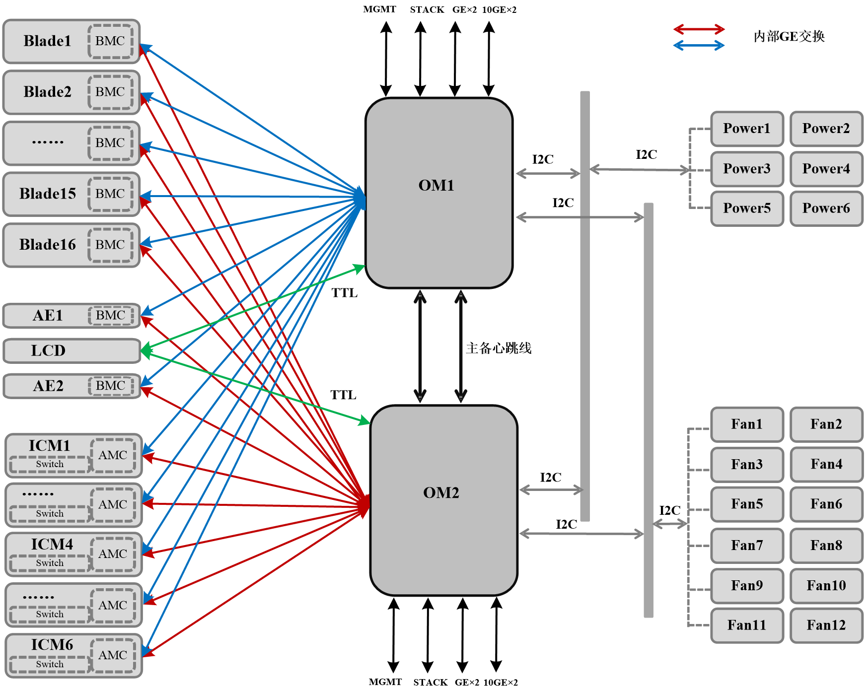
The blade server chassis manages the modules through the OM module, as shown in Figure 16.
· Two OM modules internally interconnect with each other to work in active/standby mode.
· The OM module connects to the BMCs of blade servers, BMCs of AE modules, and AMCs of interconnect modules through the internal GE management plane for out-of-band management.
· The OM module communicates and synchronizes information with the LCD module through the TTL serial port.
The LCD module and AE1 module share one slot (E1). Only one of these two modules can be installed in the slot at a time.
· The OM module manages the power supplies and fan modules through the internal I2C bus.
· Each OM module has one management port (MGMT), one cascading port (STACK), and four service ports. From the management port, you can log in to chassis management software. The cascading port is used for multi-chassis cascading. The service ports can connect the blade servers to the external network.
Figure 16 Connections of OM modules with internal modules of the blade server chassis
AE Modules
As shown in Figure 17, in the chassis, the AE module uses the four embedded network ports to connect OM modules and interconnect modules through the midplane. It connects the active and standby OM modules from the GE ports and the interconnect modules in slots 1 and 4 from the 10-GE ports. You can log in to the AE module FIST management software from the management port on the OM module or an Ethernet port on an interconnect module front panel.
Figure 17 Internal connections of the AE modules

Interconnect modules and blade servers
The number of supported Mezz network adapters and the internal connections between Mezz network adapters and interconnect modules vary with blade server models, as shown in Table 14.
Table 14 Internal connections between Mezz network adapters and interconnect modules
|
Blade server model |
Maximum Number of Supported Mezz network adapters |
Internal Connection Diagram |
|
|
H3C UniServer B5700 G3 |
3 |
NOTE: The connection diagrams are logical diagrams, presenting the connection relations between the Mezz network adapter slots and interconnect module slots. For the specific locations of the Mezz network adapter slots and interconnect module slots, see the marks on the modules. |
|
|
H3C UniServer B7800 G3 |
6 |
||
|
H3C UniServer B5800 G3 |
3 |
||
Internal connections between Mezz network adapters and interconnect modules (1)
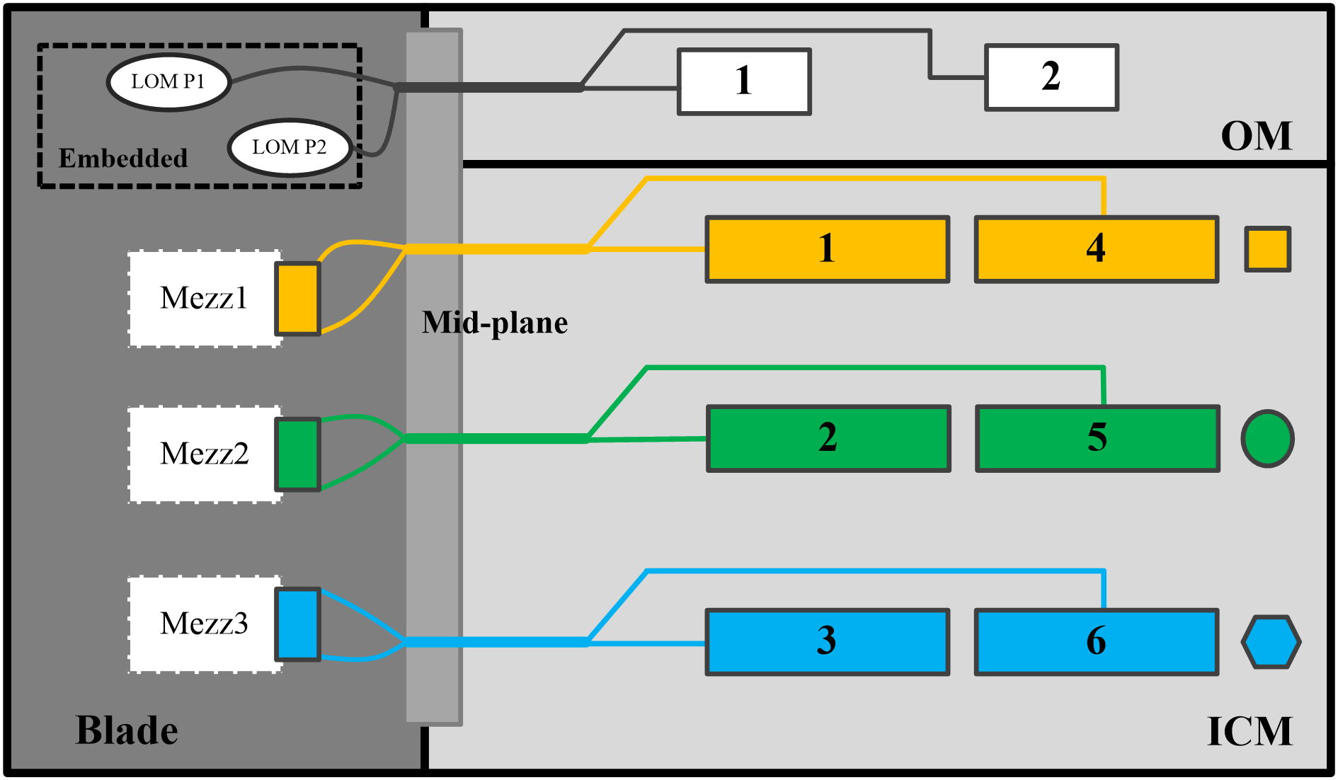
As shown in Figure 18, the following rules apply:
· The embedded network adapters are connected to the active and standby OM modules.
· Mezz network adapter 1 is connected to interconnect modules in slot 1 and slot 4.
· Mezz network adapter 2 is connected to interconnect modules in slot 2 and slot 5.
· Mezz network adapter 3 is connected to interconnect modules in slot 3 and slot 6. Figure 20 shows the slots that accommodate the interconnect modules.
Figure 18 Internal connections between Mezz network adapters and interconnect modules (1)
Internal connection between Mezz network adapter and interconnect module (2)
As shown in Figure 19, the following rules apply:
· The embedded network adapters are connected to the active and standby OM modules.
· Mezz network adapter 1 and Mezz network adapter 4 are connected to interconnect modules in slot 1 and slot 4.
· Mezz network adapter 2 and Mezz network adapter 5 are connected to interconnect modules in slot 2 and slot 5.
· Mezz network adapter 3 and Mezz network adapter 6 are connected to interconnect modules in slot 3 and slot 6. Figure 20 shows the slots that accommodate the interconnect modules.
Figure 19 Internal connections between Mezz network adapters and interconnect modules (2)
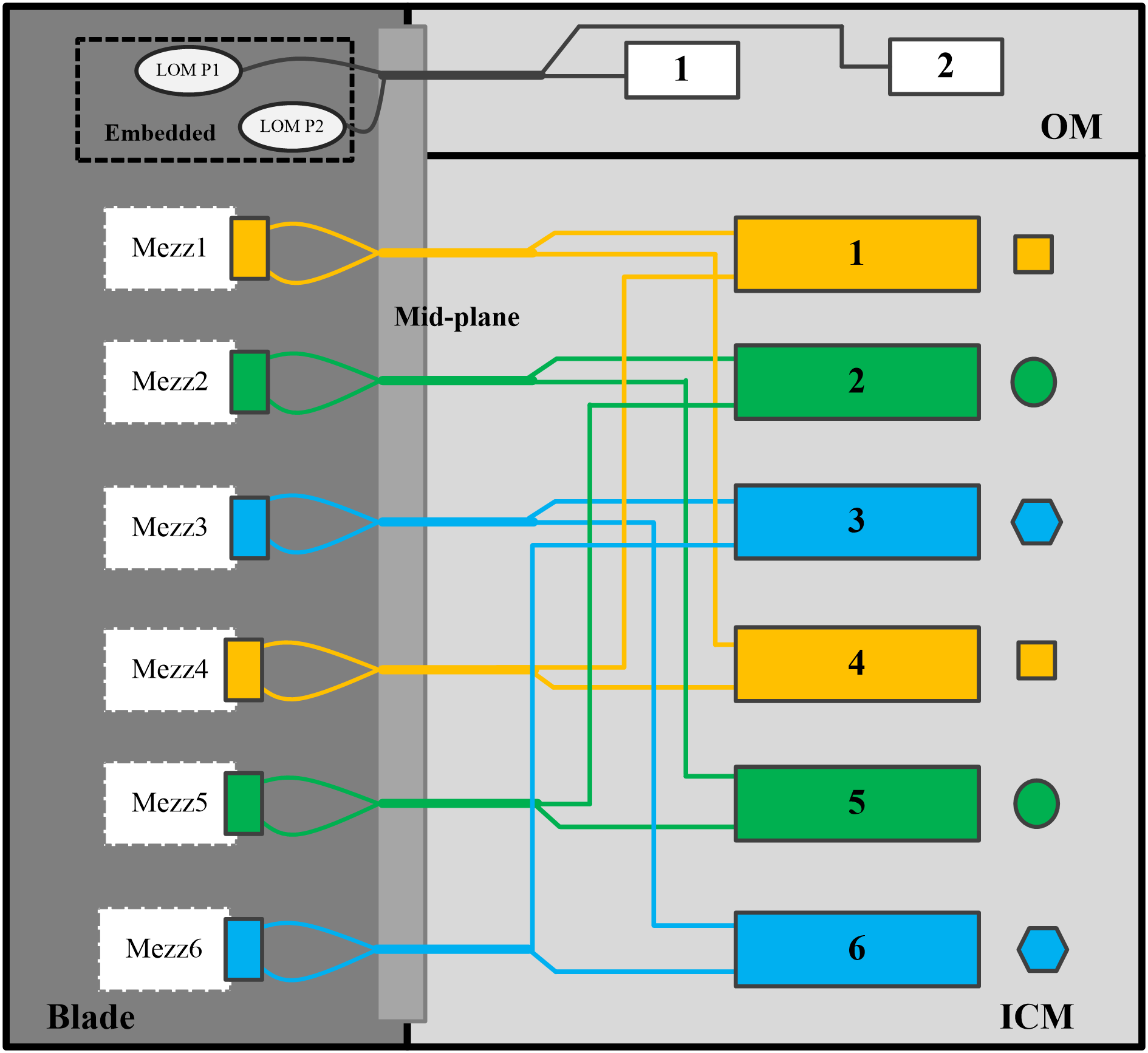
Figure 20 Interconnect module slots
Installing the blade server chassis
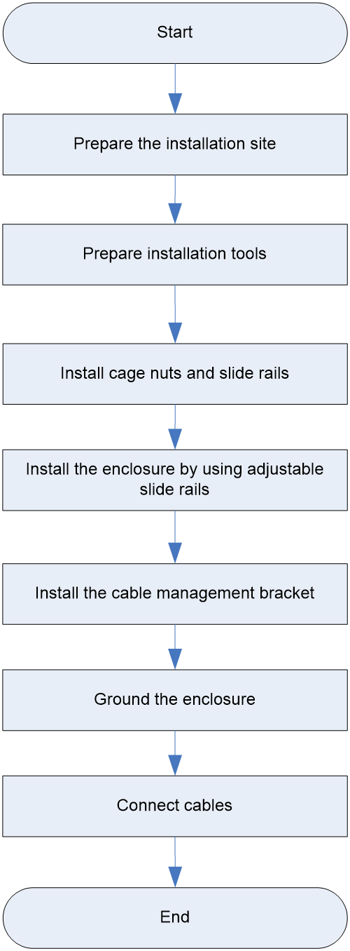
Installation flowchart
Figure 21 Chassis installation flowchart
Preparing the installation site
Prepare a rack that meets the rack requirements and plan an installation site that meets the requirements for space and airflow, temperature, humidity, equipment room height, cleanliness, and grounding.
Rack requirements
The chassis is 12U high and has a depth of 898 mm (35.35 in). Make sure the rack for installing the chassis meets the following requirements:
· A standard 19-inch rack.
· A minimum depth of 1200 mm (47.24 in). Table 15 describes limitations for installing the blade server chassis in racks with different depths.As a best practice, carry out an on-site survey before installation to eliminate potential issues.
· A minimum clearance of 80 mm (3.15 in) between the rack front posts and the front rack door.
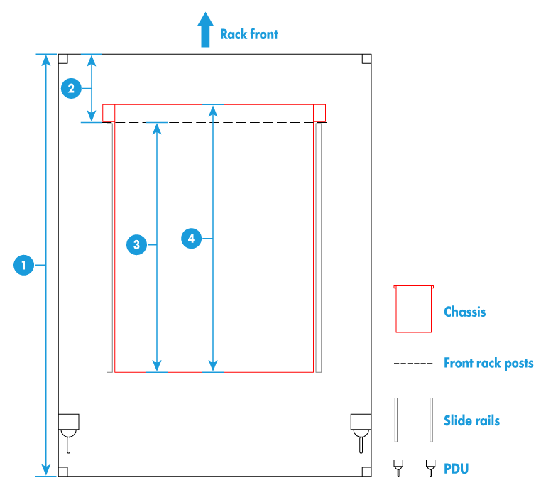
· Table 15Figure 22 provides the installation recommendations for mounting the chassis in a rack with a depth of 1200 mm (47.24 in).
Table 15 Limitations for installing the blade server chassis in racks with different depths
|
Rack depth |
Installation restrictions |
|
1000 mm (39.37 in) |
· The CMA cannot be installed. · The PCIe modules that provide interfaces from the front of the chassis cannot be installed. · The wiring space at the rear of the rack is limited. Conduct a site survey to determine whether the space meets the actual requirements. · If the internal rack width (Figure 23) is greater than or equal to 485 mm (19.09 in), use slide rails (lRL-12U) that do not occupy the rack height as a best practice. If the internal rack width is less than 485 mm (19.09 in), use slide rails (LSXM1BSR) that occupy 1U height. |
|
1100 mm (43.31 in) |
· The CMA and PCIe modules that provides interfaces from the front of the chassis cannot be installed simultaneously. · To install PCIe modules that provide interfaces from the front of the chassis, make sure the front rack posts and the front rack door is greater than 130 mm (5.12 in). · If the internal rack width (Figure 23) is greater than or equal to 485 mm (19.09 in), use slide rails (lRL-12U) that do not occupy the rack height as a best practice. If the rack mounting width is less than 485 mm (19.09 in), use slide rails (LSXM1BSR) that occupy 1U height. |
|
1200 mm (47.24 in) |
· The CMA and PCIe modules that provide interfaces from the front of the chassis can be installed simultaneously. · To install PCIe modules that provide interfaces from the front of the chassis, make sure the distance between the front rack posts and the front rack door is greater than 130 mm (5.12 in). · If the internal rack width (Figure 23) is greater than or equal to 485 mm (19.09 in), use slide rails (lRL-12U) that do not occupy the rack height as a best practice. If the rack mounting width is less than 485 mm (19.09 in), use slide rails (LSXM1BSR) that occupy 1U height. |
|
Rack dimension recommendations and requirements |
|
(1) 1200 mm (47.24 in) rack depth |
|
(2) A minimum of 80 mm (3.15 in) between the front rack posts and the front rack door |
|
As a best practice, wire PDUs from the rear to avoid interfering with the chassis. To wire the PDUs from the left or right, conduct a site survey to verify that the PDU wires do not interfere with the rear of the chassis. |
|
Chassis dimensions |
|
(3) 898 mm (35.35 in) from the front rack posts and to the chassis rear (including the power supply handles) |
|
(4) 945 mm (37.20 in) chassis depth (including the rack-mount ears) |

|
(1) Front rack posts |
(2) Rear rack posts |
|
(3) Internal rack width between the front rack posts or between the rear rack posts |
(4) Distance between the front and rear rack posts |
Space and Ventilation Requirements
For convenient maintenance and good ventilation, make sure the following requirements are met when determining a position where the rack is placed:
· The passage where the chassis is moved has a minimum clear width of 1.5 m (4.92 ft).
· Racks placed face to face have a minimum face-to-face clearance of 1.2 m (3.94 ft).
· Racks placed back to back have a minimum back-to-back clearance of 0.8 m (2.62 ft).
· The rack has a minimum of clearance of 1 m (3.28 ft) from walls.
· To avoid device damage caused by insufficient heat dissipation, do not block the ventilation openings of the chassis.
· The chassis are well ventilated at the front and rear so that ambient air enters the chassis and hot air is exhausted from the chassis smoothly.
· The air conditioner provides sufficient air volume for adequate heat dissipation of the modules in the chassis.
Airflows through blade servers, AE modules, and LCD module
Figure 24 shows the airflow through blade servers, AE modules, and LCD module.
The blade servers, AE modules, and LCD module draw in cool air from the front of the blade server chassis. After cooling internal modules inside the chassis, the air reaches the fan modules. The fan modules exhaust the hot air.
Figure 24 Airflow through the blade servers, AE modules, and LCD module (top view)
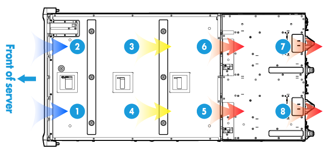
|
(1) and (2) Air intake direction |
(3) to (8) Air exhaust direction |
Airflow through interconnect modules
Figure 25 shows the airflow through interconnect module. The interconnect modules draw in cool air from the air vents at the bottom of the front of the chassis. The cool air enters the bottom of the interconnect modules through the backplane of the chassis. After cooling the interconnect modules from bottom to top, the air reaches the fan modules through the air vents on the side of the interconnect module. The fan modules exhaust the hot air.
Figure 25 Airflow through interconnect modules (side view)
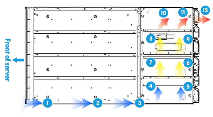
|
(1) to (5) Air intake direction |
(6) to (12) Air exhaust direction |
Airflow through power supplies
Figure 26 shows the airflow through power supplies. The power supplies draw in cool air from the air vents at the top and bottom of the front of the chassis. The cool air reaches the power supplies through the backplane of the chassis. After cooling the power supplies, the air reaches the fans provided with the power supplies. The fans exhaust the hot air.
Figure 26 Airflow through power supplies (side view)
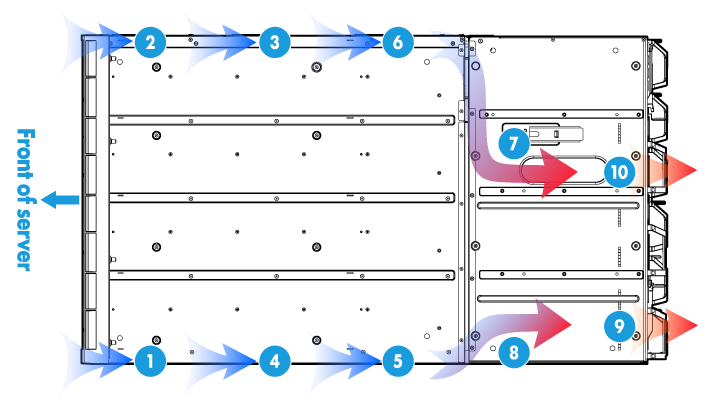
|
(1) to (6) Air intake indirection |
(7) to (10) Air exhaust direction |
Temperature and Humidity Requirements
To ensure normal operating of the device, make sure the temperature and humidity in the equipment room meet the requirements as described in "Technical specifications."
Equipment Room Height Requirements
To ensure normal operating of the device, make sure that the equipment room height meets the requirements as described in "Technical specifications."
Cleanliness Requirements
Mechanically active substance can cause safety hazards to the device. Mechanically active substance buildup on the chassis might result in electrostatic adsorption, which causes poor contact of metal components and contact points. In the worst case, for example, the relative humidity in the room is low, electrostatic adsorption can shorten the lifespan of the device and easily cause communication failure.
Table 16 describes concentration and particle diameter limits of mechanically active substance in the equipment room.
Table 16 Mechanically active substance concentration limit in the equipment room
|
Substance (Diameter) |
Concentration Limit |
Unit |
|
Dust particles (≥ 5 μm) |
≤ 3×10⁴ (No visible dust on desk within three days) |
Particles/m3 |
|
Dust (suspension) (≤ 75 μm) |
≤ 0.2 |
mg/m3 |
|
Dust (sedimentation) (75 μm to 150 μm) |
≤ 1.5 |
|
|
Sand (≥ 150 μm) |
≤ 30 |
mg/m3 |
The equipment room must also meet limits on salts, acids, and sulfides to eliminate metallic corrosion and premature aging of some components. Table 17 lists limits of harmful gases (such as SO2, H2S, NO2, NH3, and Cl2) in an equipment room.
Table 17 Harmful gas limits in an equipment room
|
Gas |
Maximum concentration (mg/m3) |
|
SO2 |
0.2 |
|
H2S |
0.006 |
|
NO2 |
0.04 |
|
NH3 |
0.05 |
|
Cl2 |
0.01 |
Grounding Requirements
Correctly connecting the ground cable of the chassis is crucial to lightning protection, anti-interference, and ESD prevention. Therefore, the chassis must be properly grounded to ensure the security. For more information, see"Grounding the chassis."
Preparing installation tools
The following table lists the tools that you might need when you install, use, and server the chassis.
|
Name |
Description |
|
|
|
Phillips screwdriver |
For fastening or loosening screws on the chassis ears, grounding cable, and backplane. |
|
|
Cage nut insertion/extraction tool |
For insertion and extraction of cage nuts in rack posts. |
|
|
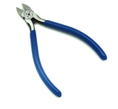
Diagonal pliers |
Cage nut insertion/extraction tool |
|
|
Tape measure |
For distance measurement. |
|
|
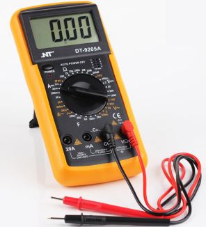
Multimeter |
For resistance and voltage measurement. |
|
|
ESD wrist strap |
For ESD prevention when you operate the chassis. |
|
|
ESD gloves |
For ESD prevention when you operate the server. |
|
|
ESD clothing |
For ESD prevention when you operate the server. |
|
|
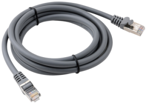
Interface cable (such as an Ethernet cable or optical fiber) |
Connects the chassis to an external network. |
|
|
Display (such as a PC) |
Used to display the output from the chassis. |


Installing cage nuts and slide rails
Before installing the chassis in the rack, install the cage nuts and slide rails on the rack.
Installing cage nuts.
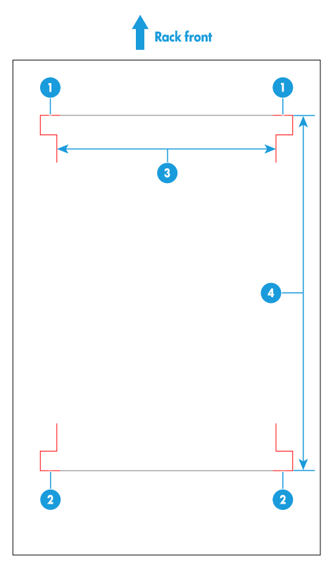
1. Use the cage nut installation template provided with the chassis to locate the installation position of cage nuts on the rack. If you install the chassis from the bottom of the rack, the cage nuts can be installed at the 4U (the 12th square hole), 9U (the 25th square hole) and 12U (the 34th square hole) positions.
Figure 27 Using the cage nut installation template
|
Note: You can hang the cage installation template on the rack through the tabs on it. |
2. Use the cage nut insertion/extraction tool to install six M6 cage nuts.
If H3C RL-12U slide rails are used, you only need to install six M6 cage nuts. If third-party slide rails are used, you might need to install eight M6 cage nuts provided with the chassis.
Installing the slide rails
Table 19 shows the H3C slide rails compatible with the chassis. For more information about about how to install slide rails, see:
· H3C RL-12U Adjustable Slide Rails Installation Guide
· H3C LSXM1BSR 1U Adjustable Rack Slide Rails Installation Guide
Skip this step if slide rails have been installed on the rack.
Table 19 Slide rails compatible with the chassis
|
Slide rail model |
Load bearing capacity |
Adjustable range |
Occupied rack space |
Requirements for the rack |
|
RL-12U |
300 kg (661.38 lb) |
700 to 900 mm (27.56 to 35.43 in) |
No space occupied |
· The distance between front and rear rack posts is within the adjustable range of the slide rails. · The internal rack width (Figure 28) is equal to or greater than 485 mm (19.09 in). |
|
LSXM1BSR |
450 kg (992.06 lb) |
630 to 900 mm (24.80 to 35.43 in) |
1 RU |
The distance between the front and rear rack posts is within the adjustable range of the slide rails. |
|
(1) Front rack posts |
(2) Rear rack posts |
|
(3) Internal rack width |
(4) Distance between the front and rear rack posts |
Installing the chassis on the adjustable slide rails
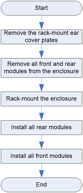
Figure 29 Flowchart for rack-mounting the chassis by using adjustable slide rails
|
|
CAUTION: As a best practice, install the chassis at the rack bottom for rack stability and easy installation. To install multiple devices on the rack, install heavier devices in the lower half of the rack. |
To rack-mount the chassis by using adjustable slide rails:
1. Remove the rack-mount ear cover plates from the chassis.
To remove a rack-mount ear cover plate, hold the plate and pull it out horizontally.
2. Remove all front and rear modules from the chassis.
To prevent bodily injury caused by overweight, remove all modules from the chassis before rack-mounting it. Record the installation slot for each module so that you can install them into their original slots after the chassis is installed on the rack.
3. Mount the chassis into the rack.
As a best practice, install the chassis at the middle lower part of the rack.
a. Attach the four handles provided with the chassis to the chassis.
To attach a handle to the chassis, insert the pegs on the chassis into the keyhole slots in the handle and push up the handle to secure it in place.
b. Use four people to move the chassis to be in front of the rack by holding the handles at the two sides of the chassis.
c. Push the chassis slowly into the rack along the slide rails until the rack-mount ears are flush against the front rack post. Remove the chassis handles one by one when pushing the chassis into the rack.
d. Fasten the eight captive screws on the rack-mount ears to secure the chassis to the rack.
e. Attach the rack-mount ear cover plates to the chassis.
To attach a rack-mount ear cover plate, fit the guide tabs on the chassis into the top and bottom guide slots of the cover plate and push the plate into place.
4. Install all rear modules on the chassis.
5. Install all front modules on the chassis.
For more information about the procedure, see Component Installation and Replacement Video.
(Optional) Installing the cable management bracket
After installing the chassis in the rack, you can attach the cable management bracket to it for cable routing.
For more infromation about the procedure, see Component Installation and Replacement Video.
To attach the cable management bracket to the chassis:
1. Place the cable management bracket down and pull it back.
2. After installing the cable management bracket, you can implement cabling according to actual requirements.
Grounding the chassis
|
|
CAUTION: · Correctly connecting the server grounding cable is crucial to lightning protection and anti-interference. Before using the chassis, connect the grounding cable to it correctly. · To guarantee the grounding effect, use the (yellow-green) grounding cable provided with the chassis to ground it. · Connect the grounding cable to the earthing system in the equipment room. Do not connect it to a fire main or lightning rod. |
To ground the chassis:
1. Remove the two screws from the grounding terminal on the chassis.
2. Use the two screws to attach the dual-hole grounding terminal of the grounding cable to the grounding point on the chassis.
3. Connect the other end of the grounding cable to a grounding strip.
For more infromation about the procedure, see Component Installation and Replacement Video.
Connecting Cables
Connecting the PC to the chassis
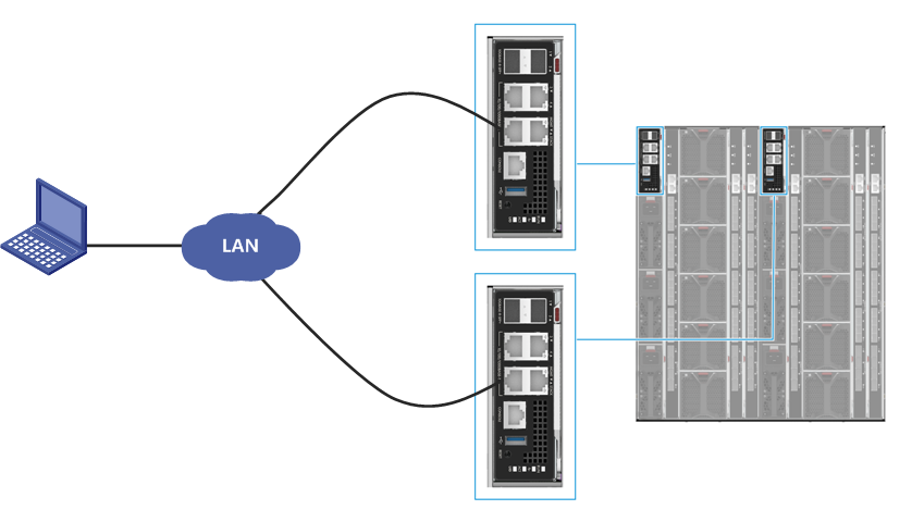
As shown in Figure 30, connect the Ethernet interface of the PC to the MGMT interface of the active or standby OM module through the LAN. Ensure that the IP addresses of the PC and OM module are accessible to each other and you can access the chassis over the PC.
Figure 30 Connecting the PC to the chassis
Cascading chassis
Scenario
Generally, you need to log in to the OM module of each chassis to manage the corresponding chassis. If multiple chassiss are configured, you can cascade them and manage all of them through the OM module of one chassis, thereby improving the operation efficiency and convenience.
In this document, assume that chassis 1 and chassis 2 are cascaded, and you can manage both blade server chassis through the OM module of chassis 1.
Procedure
|
|
NOTE: For more infromation about the procedure, see Component Installation and Replacement Video. |
To cascade chassis:
1. Connect the cascaded interface of the first management module of chassis 1 to the MGMT interface of the first management module of chassis 2.
2. Connect the cascaded interface of the second management module of chassis 1 to the MGMT interface of the second management module of chassis 2.
3. Connect the MGMT interfaces of two management modules of chassis 1 to the switch respectively.
4. Connect the PC to the switch.
5. Connect the cables for cascading the chassis. Ensure that the IP addresses of the PC and OM module of chassis 1 are accessible to each other, and you can access chassis 1 and chassis 2 through the PC.
Connecting the chassis to the network
You can connect various services provided by the blade servers in the chassis to the network through the external ports of the interconnect modules and the service ports of the OM module.
Connecting power cords for the chassis
|
|
WARNING! · Use power cords that came with the chassis. · Ensure reliable connection between each power cord and the power outlet. Make sure the power cords are grounded reliably at the power distribution room or power voltage transformer side. |
|
|
IMPORTANT: The two power cords that came with the chassis are suitable for AC or 240V high-voltage DC power supply systems. One power cord uses the PI plug and the other power cord uses the C20 plug. Select the power cord based on the power supply system in the equipment room. |
To connect a power cord:
1. Connect one end of the power cord to a power supply on the chassis and secure the power cord with a cable tie.
2. Connect the other end of the power cord to an external power supply system (such as an AC PDU or DC PDU).
Connecting the blade server to the KVM device
When maintaining a blade server, you can connect the blade server to the KVM device (keyboard, video, and mouse) through the SUV cable.
Connection method:
1. Connect one end of the SUV cable to the SUV connector of the blade server.
2. Connect another end of the SUV cable to the KVM device.
Figure 31 SUV cable
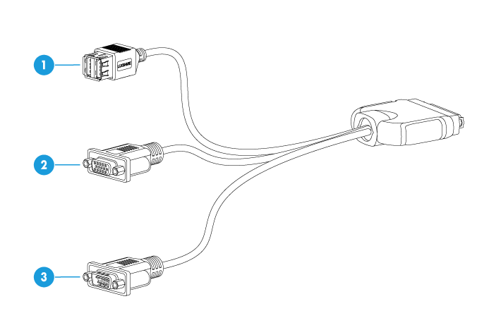
Table 20 Description of the SUV cable
|
No. |
Description |
Usage |
|
1 |
USB 2.0 connector (2 in total) |
· Connect to a USB flash drive or USB CD-ROM. · Connect to a USB keyboard or mouse. |
|
2 |
VGA connector |
Connect to the display, such as the monitor or KVM device. |
|
3 |
Serial connector |
Implement fault diagnosis or debugging. |
Powering on and powering off the chassis
This section describes how to power on/off the chassis.
Powering on the chassis
Procedure
Connect the power cords of the power supplies on the chassis to the external power source. Then, the OM modules, LCD module, and interconnect modules inside the chassis will power on automatically. Manually power on the blade servers and AE modules.
|
|
NOTE: The blade servers, interconnect modules, and AE modules all support multiple power-on methods. For more information, see the user guide for the modules. |
Powering off the chassis
Prerequisites
· Before powering off the device, you need to save all data.
· Because all services will be stopped when you power off the chassis, you need to stop all services or migrate all services to another device before powering off the device.
Procedure
1. Manually power off the blade servers, interconnect modules, and AE modules of the chassis.
2. Disconnect the power cords between the power supplies on the chassis and the external power source.
|
|
NOTE: The blade servers, interconnect modules, and AE module all support multiple power-off methods. For more information, see the user guide for the modules. |
Configuring the chassis
This section describes how to configure modules in the chassis through the PC, so that the chassis can work properly, including:
· Configuring interconnect module
Default parameters
Default OM module parameters
Table 21 Default OM module parameters
|
Item |
Default value |
Remarks |
|
Management IP address |
· Management IP address: 192.168.100.100 · Subnet mask: 255.255.255.0 |
N/A |
|
Default administrator |
· Username: admin · Password: Password@_ |
· The default administrator is the default local user instead of the LDAP user. · One chassis has only one default administrator. · The default administrator has the highest permissions of the administrator role. |
Default interconnect module parameters
Table 22 Default interconnect module parameters
|
Item |
Default value |
Remarks |
|
AMC username and password |
· Username: admin · Password: Password_UIS |
N/A |
Default blade server parameters
Table 23 Default HDM parameters for a blade server
|
Item |
Default value |
Remarks |
|
Management IP address |
The default value is obtained through the DHCP server. |
N/A |
|
Default administrator |
· Username: admin · Password: Password@_ |
N/A |
Default AE module parameters
Default HDM parameters for an AE module
Table 24 Default HDM parameters for an AE module
|
Item |
Default value |
Remarks |
|
Management IP address |
The default value is obtained through the DHCP server. |
N/A |
|
Default administrator |
· Default username: admin · Default password: Password@_ |
N/A |
Default FIST parameters for an AE module
Table 25 Default FIST parameters for an AE module
|
Item |
Default value |
Remarks |
|
Management IP address of the FIST |
Management IP address: 192.168.0.100 Mask: 255.255.255.0 |
N/A |
|
Default administrator |
· Username: admin · Password: Password@_ |
N/A |
Configuring the OM Module
This section describes how to configure basic data of the OM module. Figure 32 shows the configuration flowchart.
Figure 32 Flowchart for configuring the OM module
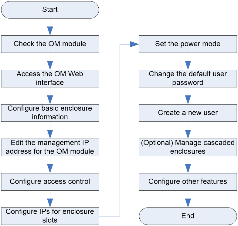
Table 26 describes the initial configuration flowchart for the OM module.
Table 26 Description for the initial configuration flowchart
|
Step |
Description |
|
Check the OM module. |
Check whether the OM module is in normal status by observing the indicator on the front panel of the OM module. |
|
Access the OM Web interface. |
N/A |
|
Configure basic information about the chassis. |
Configure basic information about the chassis, including the name, location, and asset label. |
|
Modify the management IP address of the OM module. |
The default management IP address of the OM module is 192.168.100.100/24, which can be changed according to the actual requirements. |
|
Configure access control. |
Set the remote login protocol supported by the OM module according to the actual requirements, including: · HTTPS (for Web access): This protocol is enabled by default and cannot be disabled. By default, you can access the OM module (port 443) through HTTPS connections. · HTTP: This protocol is enabled by default. If this protocol is enabled, you can access the OM module (port 80) through HTTP connections. · SSH: This protocol is enabled by default. You can access the OM module (port 22) through SSH connections. · Telnet: This protocol is disabled by default. If this protocol is enabled, you can access the OM module (port 23) through Telnet connections. · FTP: This protocol is disabled by default. If this protocol is enabled, you can access the OM module (port 21) through FTP connections. · SNMP (for MIB Browser access): This protocol is disabled by default. If this protocol is enabled, you can access the OM module through SNMP connections. ¡ SNMP version: It indicates the version of SNMP used by the user. This parameter is required. ¡ Community name: It is used to authenticate the SNMP management station by the SNMP agent. This parameter is required only when the SNMP version is SNMPv1 or SNMPv2c. ¡ SNMPv3 authentication algorithm: It supports MD5 (default) and SHA. This parameter is required only when the SNMP version is SNMPv3. ¡ SNMPv3 encryption algorithm: It supports DES (default), AES, 3DES, AES192, and AES256. This parameter is required only when the SNMP version is SNMPv3. ¡ Username and password: They indicate the username and password of the SNMPv3 user, used as the service ticket when connections are set up based on SNMPv3. This parameter is required only when the SNMP version is SNMPv3. |
|
Configure slot IP addresses. |
Pre-configure the IP information (IPv4 or IPv6) for slots, used as the management IP information of the modules inserted in the corresponding slots. |
|
Set the power mode. |
Set the power mode to ensure a stable and reliable power supply system and reduce system power consumption. |
|
Change the default user password. |
Change the default user password to ensure system security. |
|
Create a user. |
Create a user and assign the specified permissions to the user for routine maintenance. |
|
(Optional) Manage the cascaded blade server chassis. |
By cascading multiple chassis, you can manage up to eight chassis on the same page at the same time, so as to improve the management efficiency and convenience. Among multiple cascaded chassiss, only one chassis works as the primary chassis, while others work as secondary chassis. |
|
Configure other features. |
Configure other features according to actual requirements. For more infromation, see the OM online help. |
For more information about the configuration procedure. see the OM Module User Guide.
Configuring Blade Servers
After installing blade servers, you can configure settings for the blade servers, including: configuring the BIOS, configuring the RAID, installing the OS, and installing the driver.
Configuration flowchart
Figure 33 shows the flowchart for configuring a blade server.
Figure 33 Flowchart for configuring a blade server
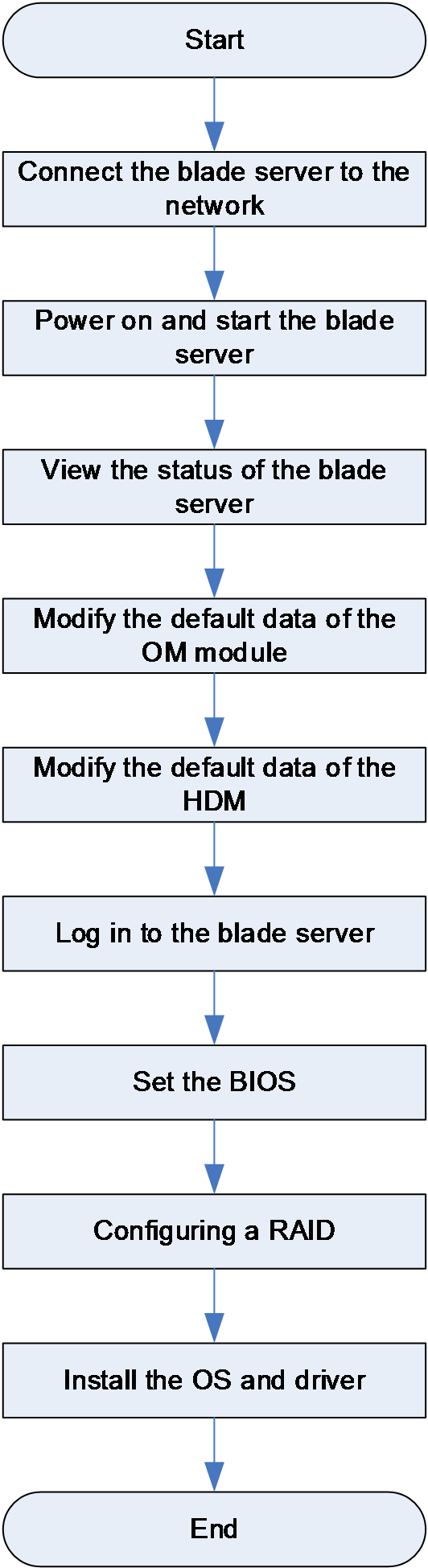
For more information about the configuration procedures, see the user guide for the corresponding blade server.
Configuring interconnect modules
This section describes how to configure basic settings for interconnect modules. Figure 34 shows the configuration flowchart.
Figure 34 Flowchart for configuring an interconnect module

Table 27 Flowchart for configuring the interconnect module
|
Step |
Description |
|
Check the interconnect module. |
Identify whether the interconnect module is normal by observing the LED on the front panel of the interconnect module. |
|
Configure the management IP address of the interconnect module. |
N/A |
|
Configure the services of the interconnect module. |
Configure the features of the interconnect module according to actual requirements. |
For more information about the configuration procedures, see the user manual and configuration guide for the interconnect module.
Configuring AE Modules
This section describes how to configure basic settings for AE modules.
Configuration flowchart
Figure 35 shows the configuration flowchart.
Figure 35 Flowchart for configuring the AE module
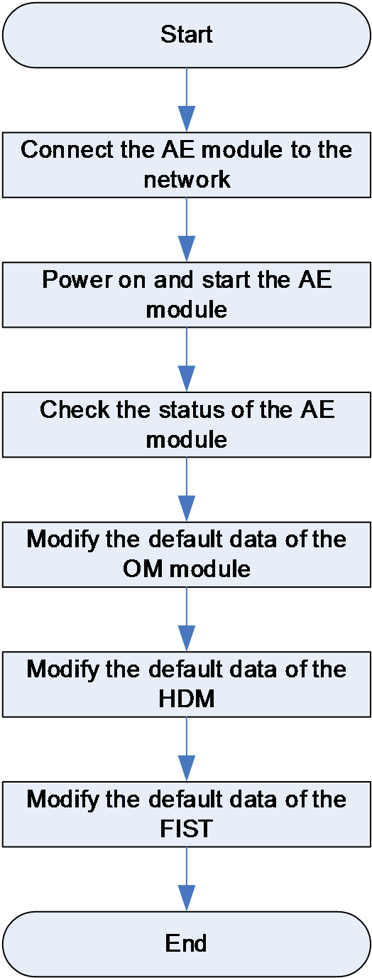
For more information about the configuration procedures, see AE Module User Guide.
Replacing Models
The following modules of the chassis can be replaced:
· Blade server
· AE module
· LCD module
· OM module
· Interconnect module
· Power supply
· Fan module
· Midplane
For more infromation about the replacement procedures, see Component Installation and Replacement Video.
Installing and Removing Blanks of All Modules
To add one of these modules to the chassis, you must first remove the blank from the slot. After removing one of these modules from the chassis, install the blank in the slot.
· Blade server
· AE module
· LCD module
· OM module
· Interconnect module
· Power supply
· Fan module
Restrictions and guidelines
To prevent electrostatic damage, take the following ESD prevention measures:
· Wear antistatic clothing.
· Wear an ESD wrist strap and make sure it makes good skin contact and is reliably grounded.
· Do not wear any conductive objects, such as jewelry or watches.
Procedure
Table 28 Procedure for installing and removing blanks of all modules
|
Item |
Procedure |
|
Remove a blade server blank. |
Hold down the buttons on both sides and horizontally pull the blank outward. |
|
Install a blade server blank. |
Horizontally push the blank into the slot with TOP facing upward. |
|
Remove an AE module or LCD module blank. |
Horizontally pull the blank outward. |
|
Install an AE module or LCD module blank. |
Horizontally push the blank into the slot with TOP facing upward. |
|
Remove an OM module blank. |
Hold down the buttons and horizontally pull the blank outward. |
|
Install an OM module blank. |
Horizontally push the blank into the slot with TOP facing upward. |
|
Remove an interconnect module blank. |
Snap into two small holes with your hands and horizontally pull the blank outward. |
|
Install an interconnect module blank. |
Horizontally push the blank into the slot with UP facing right. |
|
Remove a power supply blank. |
Horizontally pull the blank outward. |
|
Install a power supply blank. |
Horizontally push the blank into the slot with TOP facing upward. |
|
Remove a fan module blank. |
Hold down the shrapnel of the fan module and horizontally pull the blank outward. |
|
Install a fan module blank. |
Horizontally push the blank into the slot with TOP facing upward until you hear a click. |
Replacing a blade server
Scenario
· Replace the blade server with a blade server of another model.
· Maintain optional components of the blade server.
Restrictions and guidelines
· To prevent electrostatic damage, take the following ESD prevention measures:
¡ Wear antistatic clothing.
¡ Wear an ESD wrist strap and make sure it makes good skin contact and is reliably grounded.
¡ Do not wear any conductive objects, such as jewelry or watches.
· Before replacing a blade server, back up the service data, stop the services, and power off the blade server.
· When you replace a component, examine the slot and connector for damages. Make sure the pins are not damaged (bent for example) and do not contain any foreign objects.
· You might also need to remove other components when replacing the target component. For the removed components to be reinstalled correctly, record their positions and connections before removal, for example, taking pictures of cable connection or labeling cables.
· Understand the blade server installation guidelines (see"Blade Server Installation Guidelines").
Procedure
Replacing a half-width blade server
1. Press the release button of the server and fully open the ejector lever, and then pull the server gently out of the chassis.
2. Place the server into the antistatic packaging bag.
3. Take out the replacement half-width blade server from the antistatic packaging bag.
4. Press the release button of the server. The ejector lever opens automatically.
5. Insert the server gently into the chassis, and then close the ejector lever.
Replacing a full-width blade server
1. Press the release buttons of the server and fully open the ejector levers, and then pull the server gently out of the chassis.
2. Place the server in the antistatic packaging bag.
3. Take out the replacement half-width blade server from the antistatic packaging bag.
4. Press the release buttons of the server. The ejector levers open automatically.
5. Insert the server gently into the chassis, and then close the ejector levers.
Removing and installing the vertical separator
To replace half-width blade servers in an area with full-width blade servers, first remove the vertical divider in the slot. To remove the vertical divider, press the button on it, push it backward to disengage it from the chassis, and then tilt it and take it out of the chassis.
To replace full-width blade servers in an area with half-width blade servers, first install a vertical divider in the slot. To install a vertical divider, align the hooks on the divider with the grooves on the chassis and fit the hooks into the grooves, and then straight the divider up and pull it frontward to secure it in place.
Replacing an AE module
Scenario
· The AE module is faulty.
· The AE module needs to be replaced by the LCD module.
Restrictions and guidelines
· To prevent electrostatic damage, take the following ESD prevention measures:
¡ Wear antistatic clothing.
¡ Wear an ESD wrist strap and make sure it makes good skin contact and is reliably grounded.
¡ Do not wear any conductive objects, such as jewelry or watches.
· Before replacing an AE module, back up data, stop services, and then power off the AE module.
· When you replace a component, examine the slot and connector for damages. Make sure the pins are not damaged (bent for example) and do not contain any foreign objects.
· Understand the AE module installation guidelines (see "s").
Procedure
1. Press the release button on the AE module to release the ejector lever. Fully open the ejector lever, and then pull the AE module gently out of the chassis.
2. Place the AE module in the antistatic packaging bag.
3. Take out the replacement AE module from the antistatic packaging bag.
4. Press the release button to release the ejector lever.
5. Insert the AE module gently into the chassis, and then close the ejector lever.
Replacing and using an LCD module
Scenario
· The LCD module is faulty.
· The LCD module needs to be replaced by the AE module.
Restrictions and guidelines
· To prevent electrostatic damage, take the following ESD prevention measures:
¡ Wear antistatic clothing.
¡ Wear an ESD wrist strap and make sure it makes good skin contact and is reliably grounded.
¡ Do not wear any conductive objects, such as jewelry or watches.
· The LCD module is hot swappable.
· When you replace a component, examine the slot and connector for damages. Make sure the pins are not damaged (bent for example) and do not contain any foreign objects.
· Understand the LCD module installation guidelines (see "LCD module installation guidelines").
Procedure
1. Press the release button on the LCD module to release the ejector lever. Fully open the ejector lever, and then pull the LCD module gently out of the chassis.
2. Place the LCD module in the antistatic packaging bag.
3. Take out the replacement LCD module from the antistatic packaging bag.
4. Press the release button to release the ejector lever.
5. Insert the LCD module gently into the chassis, and then close the ejector lever.
Using the LCD display
1. Turn on the LCD screen. Press the button, pull the LCD display out of the chassis horizontally, and rotate it to an angle suitable for viewing.
2. To update the firmware of the LCD display, connect one end of the USB cable to the LCD display and another end to the PC.
3. Turn off the LCD display. Rotate the LCD display to a horizontal position and slowly push it into the chassis.
Replacing an OM module
Scenario
The OM module is faulty.
Restrictions and guidelines
· To prevent electrostatic damage, take the following ESD prevention measures:
¡ Wear antistatic clothing.
¡ Wear an ESD wrist strap and make sure it makes good skin contact and is reliably grounded.
¡ Do not wear any conductive objects, such as jewelry or watches.
· The OM module is hot swappable.
· Before replacing a component, check the slots and connectors, and ensure that the pins are not damaged (bent for example) and do not contain any foreign objects.
· Understand the guidelines for installing the OM module (see "OM module installation guidelines").
Procedure
1. Press the release button on the OM module to release the ejector lever. Fully open the ejector lever, and then pull the OM module gently out of the chassis.
2. Place the OM module in the antistatic packaging bag.
3. Take out the replacement OM module from the antistatic packaging bag.
4. Press the release button to release the ejector lever.
5. Orient the OM module with TOP facing upward, insert the OM module gently into the chassis, and then close the ejector lever.
Replacing an interconnect module
Scenario
· The interconnect module is faulty.
· The interconnect module needs to be replaced with an interconnect module of another model.
Restrictions and guidelines
· To prevent electrostatic damage, take the following ESD prevention measures:
¡ Wear antistatic clothing.
¡ Wear an ESD wrist strap and make sure it makes good skin contact and is reliably grounded.
¡ Do not wear any conductive objects, such as jewelry or watches.
· The interconnect module is hot swappable.
· Before replacing a component, check the slots and connectors, and ensure that the pins are not damaged (bent for example) and do not contain any foreign objects.
· Understand the guidelines for installing the interconnect module (see "Interconnect module installation guidelines").
Procedure
1. Press the release button on the interconnect module to release the ejector lever. Fully open the ejector lever, and then pull the interconnect module gently out of the chassis.
2. Place the interconnect module in the antistatic packaging bag.
3. Take out the replacement interconnect module from the antistatic packaging bag.
4. Press the release button to release the ejector lever.
5. Orient the interconnect module with TOP facing upward, insert the interconnect module gently into the chassis, and then close the ejector lever.
Replacing a power supply
Scenario
The power supply is faulty.
Restrictions and guidelines
· To prevent electrostatic damage, take the following ESD prevention measures:
¡ Wear antistatic clothing.
¡ Wear an ESD wrist strap and make sure it makes good skin contact and is reliably grounded.
¡ Do not wear any conductive objects, such as jewelry or watches.
· The power supplies are hot swappable.
· Before replacing a component, check the slots and connectors, and ensure that the pins are not damaged (bent for example) and do not contain any foreign objects.
· Understand the power supply installation guidelines (see "Power supply installation guidelines").
Procedure
1. Remove the power supply from the chassis.
Pressing the spring tab on the power supply, pull the power supply out of the chassis.
2. Place the removed power supply in the antistatic packaging bag.
3. Take out the replacement power supply from the antistatic packaging bag.
4. Push the replacement power supply gently into the chassis until it clicks into place.
Replacing the Fan Module
Scenario
The fan module is faulty.
Restrictions and guidelines
· To prevent electrostatic damage, take the following ESD prevention measures:
¡ Wear antistatic clothing.
¡ Wear an ESD wrist strap and make sure it makes good skin contact and is reliably grounded.
¡ Do not wear any conductive objects, such as jewelry or watches.
· The fan modules are hot swappable.
· Before replacing a component, check the slots and connectors, and ensure that the pins are not damaged (bent for example) and do not contain any foreign objects.
· Understand the guidelines for installing the fan module (see "Fan module installation guidelines").
Procedure
1. Remove the fan module from the chassis.
Pressing the spring tab on the fan module, pull the fan module out of the chassis.
2. Place the removed fan module in the antistatic packaging bag.
3. Take out the replacement fan module from the antistatic packaging bag.
4. Orient the fan module with TOP facing upward, push the replacement fan module gently into the chassis until it clicks into place.
Replacing the chassis midplane
Scenario
The midplane of the blade server chassis is faulty.
Restrictions and guidelines
· To prevent electrostatic damage, take the following ESD prevention measures:
¡ Wear antistatic clothing.
¡ Wear an ESD wrist strap and make sure it makes good skin contact and is reliably grounded.
¡ Do not wear any conductive objects, such as jewelry or watches.
· Before replacing the midplane, power off the chassis.
Procedure
Figure 36 Flowchart for replacing the midplane
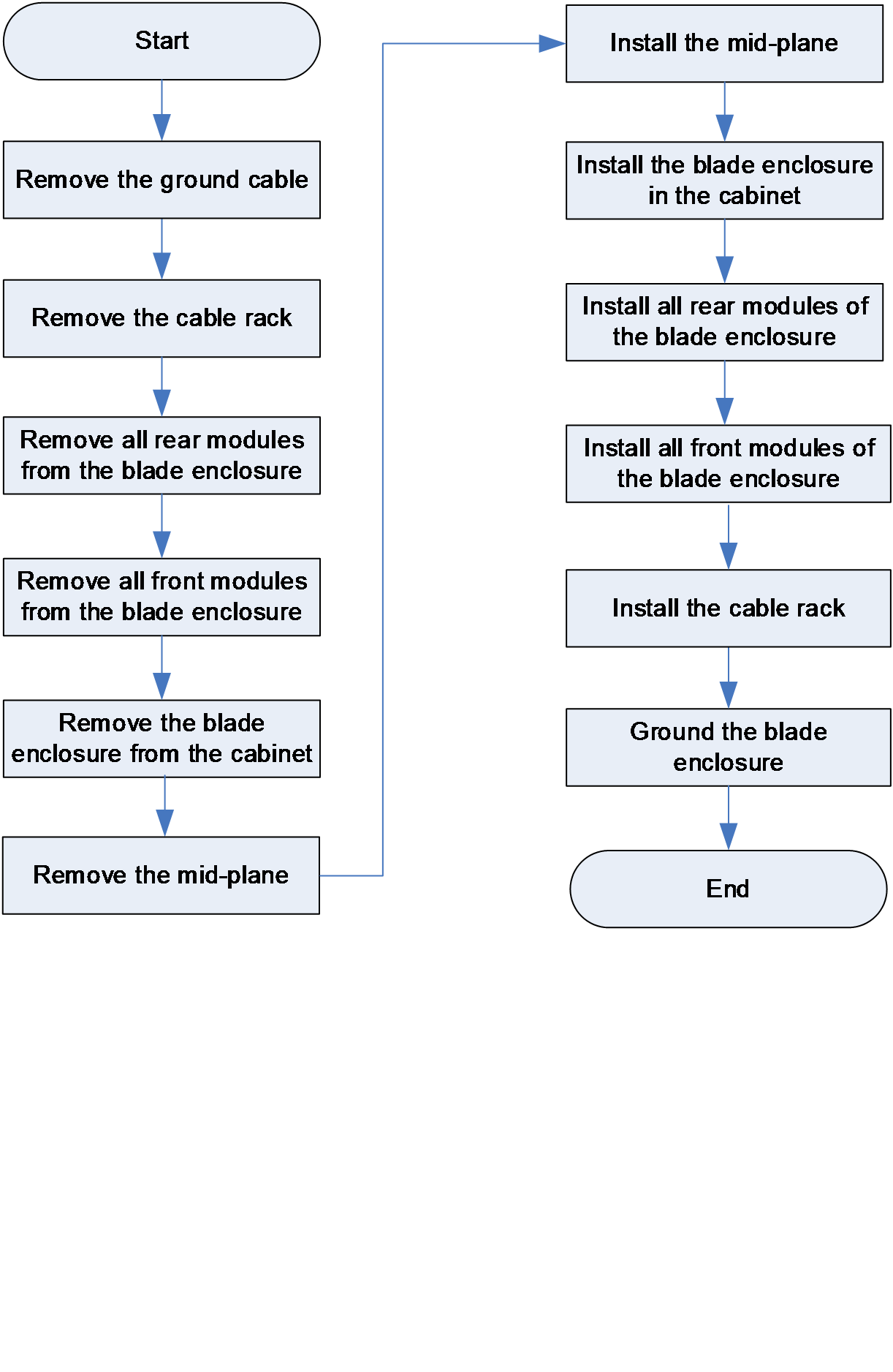
To remove the chassis midplane:
1. Remove the grounding cable.
a. Remove the grounding screws from the grounding point on the cahssis rear.
b. Remove the grounding cable.
c. Fasten the grounding screws to the ground point.
2. Removing the cable management bracket.
Lift the spring tabs and the cable management bracket will be disengaged from the cahssis automatically.
3. Remove all rear modules from the chassis.
4. Remove all front modules from the chassis.
5. Remove the chassis from the rack.
a. Remove the rack-mount ear plates. Then, remove eight screws that secure the rack-mount ears to the rack posts.
b. Pull out the chassis along the slide rails slowly. During the process, install the cahssis handles one by one.
6. Remove the mid-plane.
a. Remove seven screws on both sides of the chassis.
b. Remove eight screws on the midplane.
c. Slowly pull the midplane out of the chassis. A stuck occurs during the pulling-out process, which prevents falloff of the midplane in case of a sudden pullout.
d. Holding the pull rings and pressing the releasing tabs, slowly pull out the midplane horizontally, and then put it in an antistatic bag.
7. Install the midplane.
a. Take out the midplane to be installed from the antistatic packaging bag.
b. Holding the pull rings, push the mid-plane slowly into the chassis horizontally.
c. Fasten eight screws on the midplane.
d. Fasten seven screws on both sides of the chassis.
8. Install the chassis in the rack.
a. Attach the four handles provided with the chassis to the chassis.
To attach a handle to the chassis, align the keyhole slots in the handle with the pegs on the chassis and lift the handle to secure it in place.
b. Use four people to move the chassis to be in front of the rack by holding the handles at the two sides of the chassis.
c. Push the chassis slowly into the rack until the rack-mount ears are flush against the rack front posts. Remove the chassis handles one by one when pushing the chassis into the rack.
d. Fasten the eight captive screws on the rack-mount rears to secure the chassis to the rack.
e. Install the rack-mount ear cover plates.
To attach a plate, fit the guide tabs on the chassis into the top and bottom guide slots of the cover plate and push the plate into place.
9. Install all rear modules of the chassis.
10. Install all front modules of the chassis.
11. Install the cable management bracket.
To attach the cable management bracket to the rack, fit the keyhole pegs with the keyhole slots and pull the bracket frontward.
12. Ground the chassis.
a. Remove two grounding screws from the grounding points at the rear of the chassis.
b. Use the grounding screws to attach the dual-hole terminal of the grounding cable to the ground point on the chassis.
Adding modules and components tto the chassis
Restrictions and guidelines
· Only H3C authorized or professional engineers are allowed to operate the device.
· You can only add module models and component models supported by the chassis.
· Before expansion, back up the data to prevent data loss or service recovery failure.
· After expansion, upgrade the chassis software to ensure successful compatibility.
Adding modules to the chassis
1. Determine the types and quantity of modules to be added.
Types of modules that can be added include the blade server, AE module, LCD module, OM module, interconnect module, power supply, and fan module. Before adding modules and components, make sure the following module relationship requirements are met:
¡ The installation positions of the interconnect modules and Mezz network adapters must satisfy internal connection relationships Figure 18 and Figure 19.
¡ Determine the quantity of power supplies and configuration policies based on the overall configuration after modules are added. For more infromation, see "Power supply installation guidelines."
¡ Determine the quantity of fan modules based on the quantity of blade servers to be added. For more infromation, see "Fan module installation guidelines."
2. Installing the modules to be added.
For more infromation, see the corresponding sections in "Replacing Models."
3. Logging in to the Web interface of the OM module to identify software versions of the modules to be added and existing modules.
Figure 37 Viewing software versions on the Web interface of the OM module
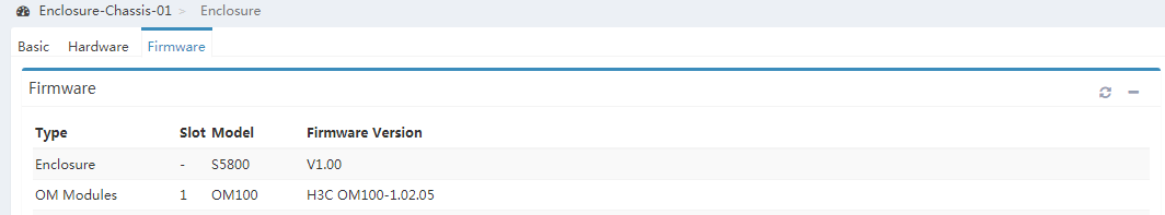
4. Idenitfy whether the software version of the modules to add match that of the existing modules.
¡ If they match, add the module to the chassis.
¡ If they do not match, obtain the required software version of the modules to add and upgrade the software version of those modules according to H3C UniServer B16000 Firmware Upgrade Guide.
Configure the to-be-added module.
For more infromation, see "Configuring the chassis."
Adding components to a blade server
1. Determine the component types and quantities to add.
The components that can be added to a blade server include processor, memory, drive, storage controller, GPU, and Mezz network adapter.
|
|
IMPORTANT: Before adding a Mezz network adapter, add an interconnect module in the corresponding slot. |
2. Install the components to be added.
a. Remove the blade server from the rack. For more information, see "Replacing a blade ."
b. Install the components to be added. For more information, see the user guide for the blade server.
c. Install the blade server. For more information, see "Replacing a blade ."
