- Table of Contents
-
- 11-Network Management and Monitoring Configuration Guide
- 00-Preface
- 01-System maintenance and debugging configuration
- 02-NQA configuration
- 03-NTP configuration
- 04-PoE configuration
- 05-SNMP configuration
- 06-RMON configuration
- 07-Event MIB configuration
- 08-NETCONF configuration
- 09-SmartMC configuration
- 10-CWMP configuration
- 11-EAA configuration
- 12-Process monitoring and maintenance configuration
- 13-Mirroring configuration
- 14-sFlow configuration
- 15-Information center configuration
- 16-Cloud connection configuration
- 17-EPA configuration
- 18-VCF fabric configuration
- Related Documents
-
| Title | Size | Download |
|---|---|---|
| 17-EPA configuration | 227.77 KB |
Endpoint identification methods
Static endpoint identification
Automatic endpoint identification
Restrictions: Software compatibility with EPA
Restrictions and guidelines: EPA configuration
Configuring static endpoint identification
Configuring dynamic endpoint identification
Display and maintenance commands for EPA
Example: Configuring static endpoint identification
Example: Configuring automatic endpoint identification (portal authentication)
Example: Configuring automatic endpoint identification (DHCP)
Configuring EPA
About EPA
Endpoint Analysis (EPA) allows you to monitor associations and disassociations of endpoints (for example, cameras and IP phones) connecting to an H3C device.
Application scenarios
Non-SmartMC networking
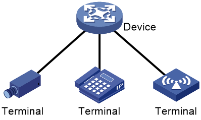
As shown in Figure 1, the device configured with EPA monitors associations and disassociations of endpoints connecting to it. The device can be a standalone device or an IRF fabric. For an IRF fabric, EPA monitors endpoints connecting to all members. The collected association and disassociation information will be reported to the master device for processing.
Figure 1 Non-SmartMC networking
SmartMC networking
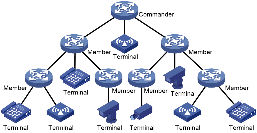
In a SmartMC network as shown in Figure 2, EPA settings are configured only on the commander. The members report association and disassociation information about their associated endpoints to the commander. The commander records such information about all associated endpoints in the network, and deploys EPA settings to the members.
You can view EPA information in the entire network on the commander.
Endpoint identification methods
EPA supports the following endpoint identification methods:
· Static identification—Identifies associations and disassociations of endpoints by matching MAC addresses of the endpoints. This method requires manual configuration of endpoint MAC addresses on the device and is applicable to networks with a small number of endpoints. This method can only identify cameras and cannot identify the vendor and operating system of cameras.
· Automatic identification—Identifies associations and disassociations of endpoints through the fields in packets. This method is applicable to networks with a large number of endpoints. This method can identify the endpoint category, vendor and operating system of endpoints. This method needs to work with BYOD.
Static endpoint identification
EPA monitors endpoint associations and disassociations by monitoring the generation and aging of MAC address entries learned by devices. A device configured with EPA can monitor only endpoints in the same subnet as the endpoint access port on the device.
For more information about MAC address entries, see Layer 2—LAN Switching Configuration Guide.
Collecting endpoint association information
If a device configured with EPA learns a new MAC address entry, it compares the MAC address and VLAN ID with the configured EPA monitor rules.
· If a match is found, the device determines that a monitored endpoint came online.
¡ In a non-SmartMC network, the device records the endpoint association event locally.
¡ In a SmartMC network, if the device is the commander, it records the endpoint association event locally. If the device is a member, it reports the event to the commander.
· If no match is found, the device determines that the endpoint is not a monitored endpoint and does not record the endpoint association event.
Collecting endpoint disassociation information
When the MAC address entry of an endpoint ages out, the device determines that the endpoint went offline.
· In a non-SmartMC network, the device records the endpoint disassociation event locally for 7 days.
· In a SmartMC network, the commander records the endpoint disassociation event for 7 days.
Synchronizing information in a SmartMC network
In a SmartMC network, endpoint monitor rules are configured on the commander and deployed to all members by the commander. The rules take effect on both the commander and members. If a member detects an association or disassociation event of a monitored endpoint, it reports the event to the commander for statistics collection and analysis.
You can view endpoint associations and disassociations that occurred in the entire network from the commander. For more information about SmartMC, see "Configuring SmartMC."
Automatic endpoint identification
As Internet technologies develop, many enterprises allow employees to use their own mobile devices (for example, mobile phones, tablets, and laptops) to access internal networks. This might create security risks. To ensure security by managing endpoints, administrators must know what endpoints are in the network, including endpoint category and endpoint operating system.
EPA can automatically identify endpoints by working with BYOD. When an endpoint accesses the network, EPA obtains fingerprint information from the authentication request of an endpoint and matches the fingerprint with the BYOD endpoint identification rules. If a match is found, EPA considers that the endpoint is online and records the MAC address, endpoint category, and vendor of the endpoint.
A BYOD endpoint identification rule is a fingerprint entry, which includes the fingerprint type, fingerprint value, endpoint category, and endpoint vendor, and endpoint OS.
BYOD supports the following endpoint fingerprints:
· DHCP Option 55 fingerprint—Parameter request list option. The option is used by an endpoint to request specified configuration parameters. To use this fingerprint, enable recording of client information in DHCP snooping entries on the access interface of endpoints. For more information about DHCP Option55 and DHCP snooping, see DHCP in Layer 3—IP Services Configuration Guide.
· HTTP user agent fingerprint—Located in the header of HTTP requests to carry information about the endpoint operating system, Web browser, and versions. To use this fingerprint, enable portal authentication on the access interface of endpoints. For more information about portal authentication, see DHCP in Security Configuration Guide.
· MAC address fingerprint—MAC address of the endpoint or MAC address range to which the endpoint belongs.
Static endpoint identification has higher priority than dynamic endpoint identification. The device matches fingerprint information for an endpoint in the following order:
1. DHCP Option 55 fingerprint.
2. HTTP user agent fingerprint.
3. MAC address fingerprint.
The system has predefined BYOD endpoint identification rules. You can also configure BYOD endpoint identification rules depending on the network requirements.
For more information about BYOD, see AAA in Security Configuration Guide.
Restrictions: Software compatibility with EPA
Only software versions of Release 1112 and later support the EPA feature.
Restrictions and guidelines: EPA configuration
Do not use the mac-address dynamic command to configure dynamic MAC address entries for monitored endpoints. If you do so, the system might fail to identify endpoint association events.
When you configure EPA in a SmartMC network, follow these restrictions and guidelines:
· Make sure all devices in the network support EPA.
· You can configure endpoint monitor rules only on the commander.
· Configure the same aging time for MAC address entries on all devices in the SmartMC network. Otherwise, endpoint association and disassociation analysis on the commander might be inaccurate. For more information about MAC address entries, see Layer 2—LAN Switching Configuration Guide.
· To view endpoint association and disassociation events in a SmartMC network, execute the display epa monitor-information command on the commander instead of a member. If you execute the command on a member, the command displays only association events of endpoints connecting to the member.
Configuring static endpoint identification
Restrictions and guidelines
When you configure static endpoint identification rules, follow these restrictions and guidelines:
· To configure multiple rules to monitor an endpoint in different VLANs, make sure the specified VLAN ranges in these rules do not overlap with each other.
· As a best practice to ensure the optimal EPA performance, specify the VLANs in which an endpoint will be monitored.
· If you configure a rule to monitor an endpoint in all VLANs, make sure the endpoint will not come online from over 10 VLANs.
· You can configure a maximum of 1024 monitor rules. As a best practice to ensure the optimal EPA performance, do not configure over 512 monitor rules.
· You can specify a rule ID when creating a monitor rule. If you do not specify the ID, the system assigns the smallest available ID to the rule.
· You cannot execute the epa monitor-rule command multiple times to edit an existing rule. To edit an existing rule, use the undo epa monitor-rule command to delete the rule and then create the rule again.
Procedure
1. Enter system view.
system-view
2. Create a static endpoint identification rule.
epa monitor-rule [ monitor-rule-id ] mac mac-address [ mask mac-mask ] [ vlan vlan-id ]
By default, no static endpoint identification rules exist.
Configuring dynamic endpoint identification
Prerequisites
The system has predefined BYOD endpoint identification rules. You can also configure BYOD endpoint identification rules depending on the network requirements (see AAA in Security Configuration Guide).
Restrictions and guidelines
After you modify a fingerprint entry, the modified parameters are reflected for matching online endpoints only if they log out and log in again.
Procedure
1. Enter system view.
system-view
2. Enable automatic endpoint identification.
epa auto-identify enable
By default, automatic endpoint identification is disabled.
Disabling EPA logging
About this task
By default, the EPA module logs endpoint associations and disassociations. If a monitored endpoint comes online or goes offline frequently, the device will generate a large number of log entries. In this case, to avoid affecting device performance, disable EPA logging as a best practice.
Procedure
1. Enter system view.
system-view
2. Disable EPA logging.
epa online-offline-log disable
By default, EPA logging is enabled.
Display and maintenance commands for EPA
Execute display commands in any view.
|
Task |
Command |
|
Display endpoint association and disassociation information detected by EPA. |
display epa monitor-information [ online | offline ] [ device device-id | mac mac-address [ vlan vlan-id ] ] [ verbose ] |
EPA configuration examples
Example: Configuring static endpoint identification
Network configuration
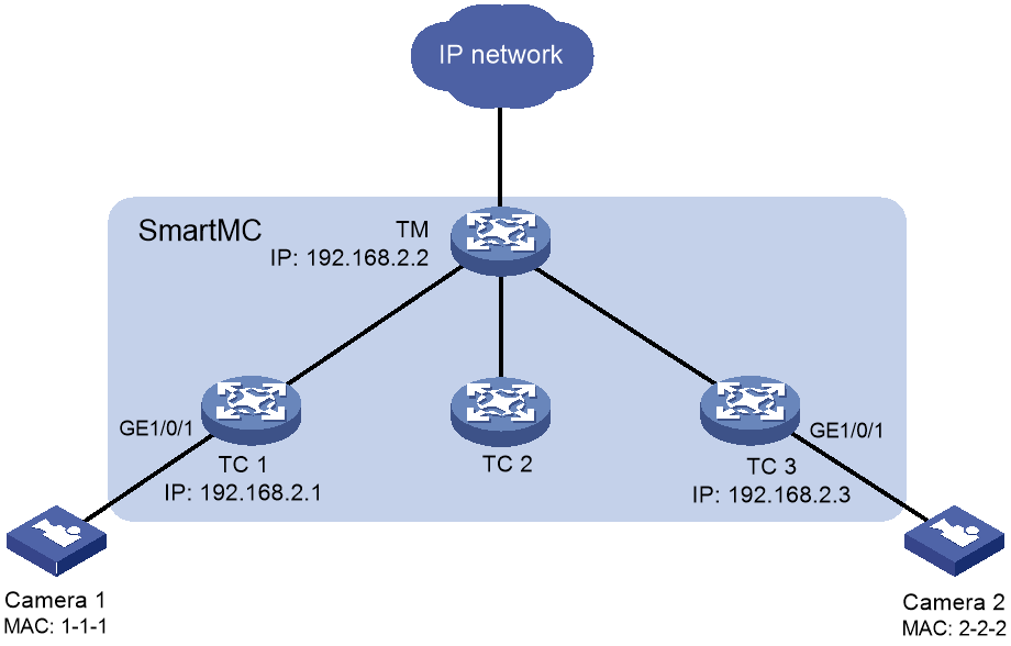
As shown in Figure 3, the SmartMC network is established manually. Configure the devices in SmartMC network so EPA can automatically identify camera 1 and camera 2 when they access the SmartMC network.
Configuring the TM
1. Configure SmartMC:
# Configure VLAN-interface 1.
[TM] interface vlan-interface 1
[TM-Vlan-interface1] ip address 192.168.2.2 24
[TM-Vlan-interface1] quit
# Enable HTTP and HTTPS.
[TM] ip http enable
[TM] ip https enable
# Enable the Telnet service.
[TM] telnet server enable
# Enable NETCONF over SOAP over HTTP.
[TM] netconf soap http enable
# Enable LLDP globally.
[TM] lldp global enable
# Create a user. Set the username to admin and password to hello12345, add the telnet, http, and https service types, and authorize the user to use the network-admin user role.
[TM] local-user admin
[TM-luser-manage-admin] password simple hello12345
[TM-luser-manage-admin] service-type telnet http https
[TM-luser-manage-admin] authorization-attribute user-role network-admin
[TM-luser-manage-admin] quit
# Set scheme authentication for VTY user lines 0 to 63.
[TM] line vty 0 63
[TM-line-vty0-63] authentication-mode scheme
[TM-line-vty0-63] quit
# Enable SmartMC, set the device role to commander, and set the username to admin and the password (plaintext) to hello12345.
[TM] smartmc tm username admin password simple hello12345 enable
2. Configure static endpoint identification rules on the commander.
[TM] epa monitor-rule mac 1-1-1
[TM] epa monitor-rule mac 2-2-2
Configuring TC 1
1. Configure SmartMC:
# Configure VLAN-interface 1.
<TC1> system-view
[TC1] interface vlan-interface 1
[TC1-Vlan-interface1] ip address 192.168.2.1 24
[TC1-Vlan-interface1] quit
# Enable HTTP and HTTPS.
[TC1] ip http enable
[TC1] ip https enable
# Enable the Telnet service.
[TC1] telnet server enable
# Enable NETCONF over SOAP over HTTP.
[TC1] netconf soap http enable
# Enable LLDP globally.
[TC1] lldp global enable
# Create a user named admin.
[TC1] local-user admin
# Lower password complexity requirements. For more information about these commands, see password control commands in Security Command Reference.
[TC1-luser-manage-admin] password-control length 4
[TC1-luser-manage-admin] password-control composition type-number 1 type-length 1
[TC1-luser-manage-admin] undo password-control complexity user-name check
# Set the username and password to admin, add the telnet, http, and https service types, and authorize the user to use the network-admin user role.
[TC1-luser-manage-admin] password simple admin
[TC1-luser-manage-admin] service-type telnet http https
[TC1-luser-manage-admin] authorization-attribute user-role network-admin
[TC1-luser-manage-admin] quit
# Set scheme authentication for VTY user lines 0 to 63.
[TC1] line vty 0 63
[TC1-line-vty0-63] authentication-mode scheme
[TC1-line-vty0-63] quit
# Enable SmartMC and set the device role to member.
[TC1] smartmc tc enable
Configuring TC 3
# Configure TC 3 in the same way TC 1 is configured. (Details not shown.)
Verifying the configuration
# On TC 1, display the online and offline information of endpoints.
[TC1] display epa monitor-information verbose
Auto identification : Disabled
Local device type : SmartMC TC
Local device ID : 3acc-58e2-0100
Total endpoints identified by EPA: 1
Access device ID: 3acc-58e2-0100
MAC address : 0001-0001-0001 VLAN : 1
IP address : -
Interface : GigabitEthernet1/0/1 Status: Online
Category : Camera Vendor: -
OS : -
# On the TM, display the online and offline information of endpoints.
[TM] display epa monitor-information verbose
Auto identification : Disabled
Local device type : SmartMC TM
Local device ID : 90bc-1b85-0300
Total endpoints identified by EPA: 2
Access device ID: 3acc-58e2-0100
MAC address : 0001-0001-0001 VLAN : 1
IP address : 192.168.2.11
Interface : GigabitEthernet1/0/1 Status: Online
Category : Camera Vendor: -
OS : -
Access device ID: 3acc-58e2-0300
MAC address : 0002-0002-0002 VLAN : 1
IP address : 192.168.2.12
Interface : GigabitEthernet1/0/1 Status: Online
Category : Camera Vendor: -
OS : -
Example: Configuring automatic endpoint identification (portal authentication)
Network configuration
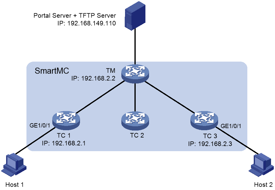
As shown in Figure 4, the SmartMC network is established automatically. Configure the devices in SmartMC network so EPA can automatically identify host 1 and host 2 when they access the SmartMC network through portal authentication.
Configuring the TM
1. Configure SmartMC:
# Configure VLAN-interface 1.
[TM] interface vlan-interface 1
[TM-Vlan-interface1] ip address 192.168.2.1 24
[TM-Vlan-interface1] quit
# Enable HTTP and HTTPS.
[TM] ip http enable
[TM] ip https enable
# Enable the Telnet service.
[TM] telnet server enable
# Enable NETCONF over SOAP over HTTP.
[TM] netconf soap http enable
# Enable LLDP globally.
[TM] lldp global enable
# Create a user. Set the username to admin and password to hello12345, add the telnet, http, and https service types, and authorize the user to use the network-admin user role.
[TM] local-user admin
[TM-luser-manage-admin] password simple hello12345
[TM-luser-manage-admin] service-type telnet http https
[TM-luser-manage-admin] authorization-attribute user-role network-admin
[TM-luser-manage-admin] quit
# Set scheme authentication for VTY user lines 0 to 63.
[TM] line vty 0 63
[TM-line-vty0-63] authentication-mode scheme
[TM-line-vty0-63] quit
# Enable SmartMC, set the device role to commander, and set the username to admin and the password (plaintext) to hello12345.
[TM] smartmc tm username admin password simple hello12345 enable
2. Enable EPA automatic endpoint identification on the commander.
[TM] epa auto-identify enable
Configuring TC 1
# Configure VLAN-interface 1.
<TC1> system-view
[TC1] interface vlan-interface 1
[TC1-Vlan-interface1] ip address 192.168.2.2 24
[TC1-Vlan-interface1] quit
# Enable HTTP and HTTPS.
[TC1] ip http enable
[TC1] ip https enable
# Enable the Telnet service.
[TC1] telnet server enable
# Enable NETCONF over SOAP over HTTP.
[TC1] netconf soap http enable
# Enable LLDP globally.
[TC1] lldp global enable
# Create a user named admin.
[TC1] local-user admin
# Lower password complexity requirements. For more information about these commands, see password control commands in Security Command Reference.
[TC1-luser-manage-admin] password-control length 4
[TC1-luser-manage-admin] password-control composition type-number 1 type-length 1
[TC1-luser-manage-admin] undo password-control complexity user-name check
# Set the username and password to admin, add the telnet, http, and https service types, and authorize the user to use the network-admin user role.
[TC1-luser-manage-admin] password simple admin
[TC1-luser-manage-admin] service-type telnet http https
[TC1-luser-manage-admin] authorization-attribute user-role network-admin
[TC1-luser-manage-admin] quit
# Set scheme authentication for VTY user lines 0 to 63.
[TC1] line vty 0 63
[TC1-line-vty0-63] authentication-mode scheme
[TC1-line-vty0-63] quit
# Enable SmartMC and set the device role to member.
[TC1] smartmc tc enable
2. Configure portal authentication:
# Create an ISP domain named dm1 and enter its view.
[TC1] domain dm1
# Configure AAA methods for the ISP domain.
[TC1-isp-dm1] authentication portal local
[TC1-isp-dm1] authorization portal local
[TC1-isp-dm1] accounting portal local
[TC1-isp-dm1] quit
# Configure a portal Web server.
[TC1] portal web-server newpt
[TC1-portal-websvr-newpt] url http://192.168.149.110:2331/portal
[TC1-portal-websvr-newpt] quit
# Enable direct portal authentication on GigabitEthernet 1/0/1.
[TC1] interface gigabitethernet 1/0/1
[TC1-GigabitEthernet1/0/1] port link-mode route
[TC1-GigabitEthernet1/0/1] ip address 192.168.149.110 16
[TC1-GigabitEthernet1/0/1] portal enable method direct
# Specify portal Web server newpt on GigabitEthernet 1/0/1.
[TC1-GigabitEthernet1/0/1] portal apply web-server newpt
[TC1-GigabitEthernet1/0/1] quit
[TC1] quit
# Download an authentication page file from a TFTP server.
<TC1> tftp 192.168.149.110 get defaultfile.zip
# Create an HTTP-based local portal Web service and enter its view.
<TC1> system-view
[TC1] portal local-web-server http
# Specify file defaultfile.zip as the default authentication page file for the local portal Web service. (Make sure the file exist under the root directory of the router.)
[TC1-portal-local-websvr-http] default-logon-page defaultfile.zip
# Set the HTTP listening port number to 2331 for the local portal Web service.
[TC1-portal-local-websvr-http] tcp-port 2331
[TC1-portal-local-websvr-http] quit
3. Configure a BYOD endpoint identification rule:
# Configure a rule to identify BYOD endpoints containing HTTP UserAgent fingerprint Mozilla/5.0.
[TC1] byod rule http-user-agent Mozilla/5.0 device-attributes
# Configure at least one piece of the following fingerprint information.
[TC1-byod-ua-Mozilla/5.0] device-category PC
[TC1-byod-ua-Mozilla/5.0] device-vendor Xerox
[TC1-byod-ua-Mozilla/5.0] device-os "Window Vista/7 or Server 2008 (Version 6.0)"
[TC1-byod-ua-Mozilla/5.0] quit
Configuring TC 3
# Configure TC 3 in the same way TC 1 is configured. (Details not shown.)
Verifying the configuration
# On TC 1, verify that EPA can successfully identify the hosts when they come online.
[TC1] display epa monitor-information verbose
Auto identification : Enabled
Local device type : SmartMC TC
Local device ID : 3acc-58e2-0100
Total endpoints identified by EPA: 1
Access device ID: 3acc-58e2-0100
MAC address : 0a00-2700-0010 VLAN : -
IP address : 192.168.226.1
Interface : GigabitEthernet1/0/1 Status: Online
Category : PC Vendor: Xerox
OS : Windows Vista/7 or Server 2008 (Version 6.0)
# On the TM, verify that EPA can successfully identify the hosts when they come online.
[TM] display epa monitor-information verbose
Auto identification : Enabled
Local device type : SmartMC TM
Local device ID : 90bc-1b85-0300
Total endpoints identified by EPA: 2
Access device ID: 3acc-58e2-0100
MAC address : 0001-0001-0001 VLAN : -
IP address : 192.168.226.1
Interface : GigabitEthernet1/0/1 Status: Online
Category : PC Vendor: Xerox
OS : Windows Vista/7 or Server 2008 (Version 6.0)
Access device ID: 3acc-58e2-0300
MAC address : 0002-0002-0002 VLAN : -
IP address : 192.168.226.2
Interface : GigabitEthernet1/0/1 Status: Online
Category : PC Vendor: Xerox
OS : Windows Vista/7 or Server 2008 (Version 6.0)
Example: Configuring automatic endpoint identification (DHCP)
Network configuration
As shown in Figure 5, the SmartMC network is established automatically. Configure the devices in SmartMC network so EPA can automatically identify host 1 and host 2 when they access the SmartMC network through DHCP.
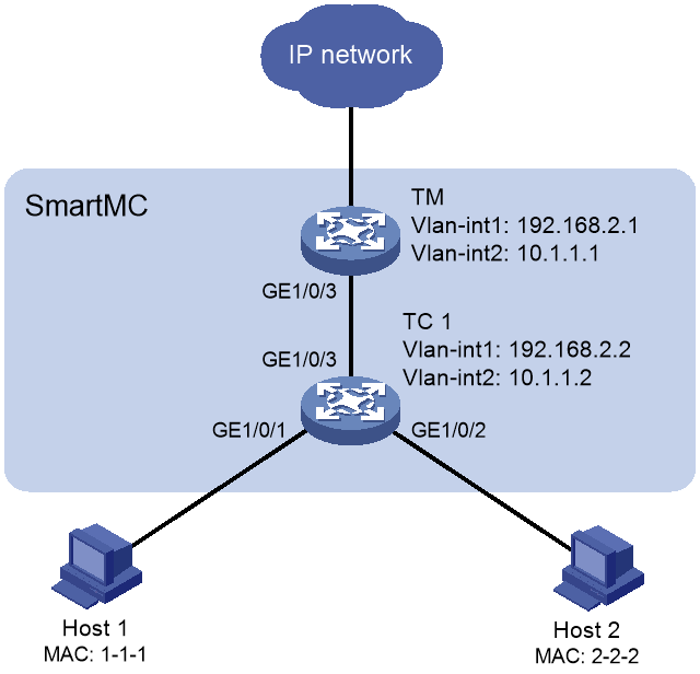
Configuring the TM
1. Configure SmartMC:
# Configure VLAN-interface 1.
[TM] interface vlan-interface 1
[TM-Vlan-interface1] ip address 192.168.2.1 24
[TM-Vlan-interface1] quit
# Enable HTTP and HTTPS.
[TM] ip http enable
[TM] ip https enable
# Enable the Telnet service.
[TM] telnet server enable
# Enable NETCONF over SOAP over HTTP.
[TM] netconf soap http enable
# Enable LLDP globally.
[TM] lldp global enable
# Create a user. Set the username to admin and password to hello12345, add the telnet, http, and https service types, and authorize the user to use the network-admin user role.
[TM] local-user admin
[TM-luser-manage-admin] password simple hello12345
[TM-luser-manage-admin] service-type telnet http https
[TM-luser-manage-admin] authorization-attribute user-role network-admin
[TM-luser-manage-admin] quit
# Set scheme authentication for VTY user lines 0 to 63.
[TM] line vty 0 63
[TM-line-vty0-63] authentication-mode scheme
[TM-line-vty0-63] quit
# Enable SmartMC, set the device role to commander, and set the username to admin and the password (plaintext) to hello12345.
[TM] smartmc tm username admin password simple hello12345 enable
2. Configure the DHCP server:
# Configure VLAN-interface 2.
<TM> system-view
[TM] vlan 2
[TM-vlan2] quit
[TM] interface vlan-interface 2
[TM-Vlan-interface2] ip address 10.1.1.1 24
[TM-Vlan-interface2] quit
# Exclude the IP address of the DNS server from dynamic allocation.
[TM] dhcp server forbidden-ip 10.1.1.2
# Configure DHCP address pool 0 to assign IP addresses and other configuration parameters to clients on subnet 10.1.1.0/24.
[TM] dhcp server ip-pool 0
[TM-dhcp-pool-0] network 10.1.1.0 mask 255.255.255.0
[TM-dhcp-pool-0] expired day 10
[TM-dhcp-pool-0] quit
# Enable DHCP.
[RouterA] dhcp enable
3. Enable EPA automatic endpoint identification on the commander.
[TM] epa auto-identify enable
4. Configure GigabitEthernet 1/0/3.
[TM] interface gigabitethernet 1/0/3
[TM-GigabitEthernet1/0/3] port link-type trunk
[TM-GigabitEthernet1/0/3] port trunk permit vlan all
Configuring TC 1
1. Configure SmartMC:
# Configure VLAN-interface 1.
<TC1> system-view
[TC1] interface vlan-interface 1
[TC1-Vlan-interface1] ip address 192.168.2.2 24
[TC1-Vlan-interface1] quit
# Enable HTTP and HTTPS.
[TC1] ip http enable
[TC1] ip https enable
# Enable the Telnet service.
[TC1] telnet server enable
# Enable NETCONF over SOAP over HTTP.
[TC1] netconf soap http enable
# Enable LLDP globally.
[TC1] lldp global enable
# Create a user named admin.
[TC1] local-user admin
# Lower password complexity requirements. For more information about these commands, see password control commands in Security Command Reference.
[TC1-luser-manage-admin] password-control length 4
[TC1-luser-manage-admin] password-control composition type-number 1 type-length 1
[TC1-luser-manage-admin] undo password-control complexity user-name check
# Set the username and password to admin, add the telnet, http, and https service types, and authorize the user to use the network-admin user role.
[TC1-luser-manage-admin] password simple admin
[TC1-luser-manage-admin] service-type telnet http https
[TC1-luser-manage-admin] authorization-attribute user-role network-admin
[TC1-luser-manage-admin] quit
# Set scheme authentication for VTY user lines 0 to 63.
[TC1] line vty 0 63
[TC1-line-vty0-63] authentication-mode scheme
[TC1-line-vty0-63] quit
# Enable SmartMC and set the device role to member.
[TC1] smartmc tc enable
2. Configure DHCP snooping:
# Enable DHCP snooping globally.
<TC1> system-view
[TC1] dhcp snooping enable
# Assign an IP address to VLAN-interface 2.
[TC1] vlan 2
[TC1-vlan2] quit
[TC1] interface vlan-interface 2
[TC1-Vlan-interface2] ip address 10.1.1.2 24
[TC1-Vlan-interface2] quit
# Assign GigabitEthernet 1/0/1 to VLAN 2, and configure it as a trusted port.
[TC1] interface gigabitethernet 1/0/1
[TC1-GigabitEthernet1/0/1] port access vlan 2
[TC1-GigabitEthernet1/0/1] dhcp snooping trust
[TC1-GigabitEthernet1/0/1] quit
# Assign GigabitEthernet 1/0/2 to VLAN 2, and configure it as a trusted port.
[TC1] interface gigabitethernet 1/0/2
[TC1-GigabitEthernet1/0/2] port access vlan 2
[TC1-GigabitEthernet1/0/2] dhcp snooping trust
[TC1-GigabitEthernet1/0/2] quit
3. Configure GigabitEthernet 1/0/3.
[TC1] interface gigabitethernet 1/0/3
[TC1-GigabitEthernet1/0/3] port link-type trunk
[TC1-GigabitEthernet1/0/3] port trunk permit vlan all
4. Configure a BYOD endpoint identification rule:
If you use the default fingerprint information, skip this step.
# Configure a rule to identify BYOD endpoints containing DHCP Option55 fingerprint 1,121,3,6,12,15,33,43,66,67,138,150.
[TC1] byod rule dhcp-option 1,121,3,6,12,15,33,43,66,67,138,150 device-attribute
# Configure at least one piece of the following fingerprint information.
[TC1-byod-opt-1,121,3,6,12,15,33,43,66,67,138,150] device-category PC
[TC1-byod-opt-1,121,3,6,12,15,33,43,66,67,138,150] device-vendor Xerox
[TC1-byod-opt-1,121,3,6,12,15,33,43,66,67,138,150] device-os "Window Vista/7 or Server 2008 (Version 6.0)"
[TC1-byod-opt-1,121,3,6,12,15,33,43,66,67,138,150] quit
5. Configure host 1 and host 2 to obtain IP addresses through DHCP.
Verifying the configuration
# On TC 1, verify that EPA can successfully identify the hosts when they come online.
[TC1] display epa monitor-information verbose
Auto identification : Enabled
Local device type : SmartMC TC
Local device ID : 3acc-58e2-0100
Total endpoints identified by EPA: 2
Access device ID: 3acc-58e2-0100
MAC address : 0001-0001-0001 VLAN : 2
IP address : 10.1.1.3
Interface : GigabitEthernet1/0/1 Status: Online
Category : PC Vendor: Xerox
OS : Window Vista/7 or Server 2008 (Version 6.0)
Access device ID: 3acc-58e2-0100
MAC address : 0002-0002-0002 VLAN : 2
IP address : 10.1.1.4
Interface : GigabitEthernet1/0/2 Status: Online
Category : PC Vendor: Xerox
OS : Window Vista/7 or Server 2008 (Version 6.0)
# On the TM, verify that EPA can successfully identify the hosts when they come online.
[TM] display epa monitor-information verbose
Auto identification : Enabled
Local device type : SmartMC TM
Local device ID : 90bc-1b85-0300
Total endpoints identified by EPA: 2
Access device ID: 3acc-58e2-0100
MAC address : 0001-0001-0001 VLAN : 2
IP address : 10.1.1.3
Interface : GigabitEthernet1/0/1 Status: Online
Category : PC Vendor: Xerox
OS : Window Vista/7 or Server 2008 (Version 6.0)
Access device ID: 3acc-58e2-0100
MAC address : 0001-0001-0001 VLAN : 2
IP address : 10.1.1.4
Interface : GigabitEthernet1/0/2 Status: Online
Category : PC Vendor: Xerox
OS : Window Vista/7 or Server 2008 (Version 6.0)
