- Table of Contents
-
- 03-Layer 2—LAN Switching Configuration Guide
- 00-Preface
- 01-MAC address table configuration
- 02-PPPoE relay configuration
- 03-Bulk interface configuration
- 04-Ethernet interface configuration
- 05-Ethernet link aggregation configuration
- 06-Port isolation configuration
- 07-VLAN configuration
- 08-MVRP configuration
- 09-Loopback, null, and inloopback interface configuration
- 10-QinQ configuration
- 11-VLAN mapping configuration
- 12-Loop detection configuration
- 13-Spanning tree configuration
- 14-LLDP configuration
- 15-L2PT configuration
- Related Documents
-
| Title | Size | Download |
|---|---|---|
| 04-Ethernet interface configuration | 195.19 KB |
Contents
Configuring Ethernet interfaces
Configuring a management Ethernet interface
Ethernet interface naming conventions
Configuring common Ethernet interface settings
Configuring basic settings of an Ethernet interface
Enabling automatic negotiation for speed downgrading
Configuring jumbo frame support
Configuring physical state change suppression on an Ethernet interface
Configuring dampening on an Ethernet interface
Configuring link flapping protection on an Ethernet interface
Configuring generic flow control on an Ethernet interface
Enabling energy saving features on an Ethernet interface
Setting the statistics polling interval
Enabling loopback testing on an Ethernet interface
Forcibly bringing up a fiber port
Shutting down all physical interfaces
Restoring the default settings for an interface
Configuring a Layer 2 Ethernet interface
Setting speed options for autonegotiation on an Ethernet interface
Setting the MDIX mode of an Ethernet interface
Configuring storm control on an Ethernet interface
Testing the cable connection of an Ethernet interface
Enabling bridging on an Ethernet interface
Display and maintenance commands for Ethernet interfaces
Configuring Ethernet interfaces
About Ethernet interface
The Switch Series supports Ethernet interfaces, management Ethernet interfaces, Console interfaces. For the interface types and the number of interfaces supported by a switch model, see the installation guide.
This chapter describes how to configure management Ethernet interfaces and Ethernet interfaces.
Configuring a management Ethernet interface
About this task
A management interface uses an RJ-45/LC connector. You can connect the interface to a PC for software loading and system debugging, or connect it to a remote NMS for remote system management.
Procedure
1. Enter system view.
system-view
2. Enter management Ethernet interface view.
interface M-GigabitEthernet interface-number
3. (Optional.) Set the interface description.
description text
The default setting is M-GigabitEthernet0/0/0 Interface.
4. (Optional.) Set the duplex mode for the management Ethernet interface.
duplex { auto | full | half }
By default, the duplex mode is auto for a management Ethernet interface.
5. (Optional.)_Set the speed for the management Ethernet interface.
speed { 10 | 100 | 1000 | auto }
By default, the speed is auto for a management Ethernet interface.
6. (Optional.) Shut down the interface.
shutdown
By default, the management Ethernet interface is up.
|
|
CAUTION: Executing the shutdown command on an interface will disconnect the link of the interface and interrupt communication. Use this command with caution. |
Ethernet interface naming conventions
The Ethernet interfaces are named in the format of interface type A/B/C. The letters that follow the interface type represent the following elements:
· A—IRF member ID. If the switch is not in an IRF fabric, A is 1 by default.
· B—Card slot number. 0 indicates the interface is a fixed interface of the switch.
· C—Port index.
Configuring common Ethernet interface settings
Configuring basic settings of an Ethernet interface
About this task
You can configure an Ethernet interface to operate in one of the following duplex modes:
· Full-duplex mode—The interface can send and receive packets simultaneously.
· Half-duplex mode—The interface can only send or receive packets at a given time.
· Autonegotiation mode—The interface negotiates a duplex mode with its peer.
You can set the speed of an Ethernet interface or enable it to automatically negotiate a speed with its peer. For a 100-Mbps or 1000-Mbps Layer 2 Ethernet interface, you can also set speed options for autonegotiation. The two ends can select a speed only from the available options. For more information, see "Setting speed options for autonegotiation on an Ethernet interface."
Restrictions and guidelines
The shutdown, port up-mode, and loopback commands are mutually exclusive.
Procedure
1. Enter system view.
system-view
2. Enter Ethernet interface view.
interface interface-type interface-number
3. Set the description for the Ethernet interface.
description text
The default setting is interface-name Interface. For example, GigabitEthernet1/0/1 Interface.
4. Set the duplex mode for the Ethernet interface.
duplex { auto | full | half }
By default, the duplex mode is auto for Ethernet interfaces.
Fiber ports do not support the half keyword.
5. Set the speed for the Ethernet interface.
speed { 10 | 100 | 1000 | 10000 | auto }
By default, an Ethernet interface negotiates a speed with its peer.
6. Set the expected bandwidth for the Ethernet interface.
bandwidth bandwidth-value
By default, the expected bandwidth (in kbps) is the interface baud rate divided by 1000.
7. Bring up the Ethernet interface.
undo shutdown
By default, Ethernet interfaces are in up state.
Enabling automatic negotiation for speed downgrading
About this task
Perform this task to enable interfaces at two ends of a link to automatically negotiate about downgrading their speed when the following conditions exist:
· The interfaces automatically negotiate a speed of 1000 Mbps.
· The interfaces cannot operate at 1000 Mbps because of link restrictions.
Restrictions and guidelines
This feature is available only on GE interfaces.
Procedure
1. Enter system view.
system-view
2. Enter Ethernet interface view.
interface interface-type interface-number
3. Enable automatic negotiation for speed downgrading.
speed auto downgrade
By default, automatic negotiation for speed downgrading is enabled.
Configuring jumbo frame support
About this task
Jumbo frames are frames larger than 1522 bytes and are typically received by an Ethernet interface during high-throughput data exchanges, such as file transfers.
The Ethernet interface processes jumbo frames in the following ways:
· When the Ethernet interface is configured to deny jumbo frames (by using the undo jumboframe enable command), the Ethernet interface discards jumbo frames.
· When the Ethernet interface is configured with jumbo frame support, the Ethernet interface performs the following operations:
¡ Processes jumbo frames within the specified length.
¡ Discards jumbo frames that exceed the specified length.
Procedure
1. Enter system view.
system-view
2. Enter Ethernet interface view.
interface interface-type interface-number
3. Configure jumbo frame support.
jumboframe enable [ size ]
By default, the device allows jumbo frames within 12288 bytes to pass through.
If you set the size argument multiple times, the most recent configuration takes effect.
Configuring physical state change suppression on an Ethernet interface
About this task
The physical link state of an Ethernet interface is either up or down. Each time the physical link of an interface comes up or goes down, the interface immediately reports the change to the CPU. The CPU then performs the following operations:
· Notifies the upper-layer protocol modules (such as routing and forwarding modules) of the change for guiding packet forwarding.
· Automatically generates traps and logs to inform users to take the correct actions.
To prevent frequent physical link flapping from affecting system performance, configure physical state change suppression. You can configure this feature to suppress only link-down events, only link-up events, or both. If an event of the specified type still exists when the suppression interval expires, the system reports the event to the CPU.
Restrictions and guidelines
Do not enable this feature on an interface that has RRPP, spanning tree protocols, or Smart Link enabled.
You can configure different suppression intervals for link-up and link-down events.
If you execute the link-delay command multiple times on an interface, the following rules apply:
· You can configure the suppression intervals for link-up and link-down events separately.
· If you configure the suppression interval multiple times for link-up or link-down events, the most recent configuration takes effect.
The link-delay, dampening, and port link-flap protect enable commands are mutually exclusive on an Ethernet interface.
Procedure
1. Enter system view.
system-view
2. Enter Ethernet interface view.
interface interface-type interface-number
3. Configure physical state change suppression.
link-delay { down | up } [ msec ] delay-time
By default, each time the physical link of an interface goes up or comes down, the interface immediately reports the change to the CPU.
Configuring dampening on an Ethernet interface
About this task
The interface dampening feature uses an exponential decay mechanism to prevent excessive interface flapping events from adversely affecting routing protocols and routing tables in the network. Suppressing interface state change events protects the system resources.
If an interface is not dampened, its state changes are reported. For each state change, the system also generates an SNMP trap and log message.
After a flapping interface is dampened, it does not report its state changes to the CPU. For state change events, the interface only generates SNMP trap and log messages.
Parameters
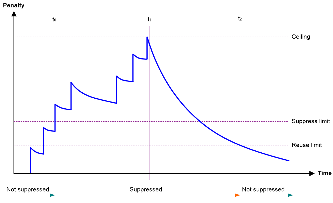
· Penalty—The interface has an initial penalty of 0. When the interface flaps, the penalty increases by 1000 for each down event until the ceiling is reached. It does not increase for up events. When the interface stops flapping, the penalty decreases by half each time the half-life timer expires until the penalty drops to the reuse threshold.
· Ceiling—The penalty stops increasing when it reaches the ceiling.
· Suppress-limit—The accumulated penalty that triggers the device to dampen the interface. In dampened state, the interface does not report its state changes to the CPU. For state change events, the interface only generates SNMP traps and log messages.
· Reuse-limit—When the accumulated penalty decreases to this reuse threshold, the interface is not dampened. Interface state changes are reported to the upper layers. For each state change, the system also generates an SNMP trap and log message.
· Decay—The amount of time (in seconds) after which a penalty is decreased.
· Max-suppress-time—The maximum amount of time the interface can be dampened. If the penalty is still higher than the reuse threshold when this timer expires, the penalty stops increasing for down events. The penalty starts to decrease until it drops below the reuse threshold.
When configuring the dampening command, follow these rules to set the values mentioned above:
· The ceiling is equal to 2(Max-suppress-time/Decay) × reuse-limit. It is not user configurable.
· The configured suppress limit is lower than or equal to the ceiling.
· The ceiling is lower than or equal to the maximum suppress limit supported.
Figure 1 shows the change rule of the penalty value. The lines t0 and t2 indicate the start time and end time of the suppression, respectively. The period from t0 to t2 indicates the suppression period, t0 to t1 indicates the max-suppress-time, and t1 to t2 indicates the complete decay period.
Figure 1 Change rule of the penalty value
Restrictions and guidelines
· The dampening, link-delay, and port link-flap protect enable commands are mutually exclusive on an interface.
· The dampening command does not take effect on the administratively down events. When you execute the shutdown command, the penalty restores to 0, and the interface reports the down event to the upper-layer protocols.
· Do not enable the dampening feature on an interface with RRPP, MSTP, or Smart Link enabled.
Procedure
1. Enter system view.
system-view
2. Enter Ethernet interface view.
interface interface-type interface-number
3. Enable dampening on the interface.
dampening [ half-life reuse suppress max-suppress-time ]
By default, interface dampening is disabled on Ethernet interfaces.
Configuring link flapping protection on an Ethernet interface
About this task
Link flapping on an interface changes network topology and increases the system overhead. For example, in an active/standby link scenario, when interface status on the active link changes between UP and DOWN, traffic switches between active and standby links. To solve this problem, configure this feature on the interface.
With this feature enabled on an interface, when the interface goes down, the system enables link flapping detection. During the link flapping detection interval, if the number of detected flaps reaches or exceeds the link flapping detection threshold, the system shuts down the interface.
Software version and feature compatibility
This feature is supported only in R1107 and later.
Restrictions and guidelines
This feature takes effect only if it is configured in both the system view and interface view.
IRF system stability might be affected by IRF physical link flapping. For IRF system stability, this feature is enabled by default on IRF physical interfaces and the enabling status of this feature is not affected by the status of global link flapping protection. When the number of flaps detected on an IRF physical interface exceeds the threshold within the detection interval, the device outputs a log rather than shuts down the IRF physical interface.
The dampening, link-delay, and port link-flap protect enable commands are mutually exclusive on an Ethernet interface.
To bring up an interface that has been shut down by link flapping protection, execute the undo shutdown command.
In the display interface command output, the Link-Flap DOWN value of the Current state field indicates that the interface has been shut down by link flapping protection.
Procedure
1. Enter system view.
system-view
2. Enable link flapping protection globally.
link-flap protect enable
By default, link flapping protection is disabled globally.
3. Enter Ethernet interface view.
interface interface-type interface-number
4. Enable link flapping protection on the Ethernet interface.
port link-flap protect enable [ interval interval | threshold threshold ] *
By default, link flapping protection is disabled on an Ethernet interface.
Configuring storm suppression
About this task
The storm suppression feature ensures that the size of a particular type of traffic (broadcast, multicast, or unknown unicast traffic) does not exceed the threshold on an interface. When the broadcast, multicast, or unknown unicast traffic on the interface exceeds this threshold, the system discards packets until the traffic drops below this threshold.
Both storm suppression and storm control can suppress storms on an interface. Storm suppression uses the chip to suppress traffic. Storm suppression has less impact on the device performance than storm control, which uses software to suppress traffic.
Restrictions and guidelines
· For the traffic suppression result to be determined, do not configure storm control together with storm suppression for the same type of traffic. For more information about storm control, see "Configuring storm control on an Ethernet interface."
Procedure
system-view
2. Enter Ethernet interface view.
interface interface-type interface-number
3. Enable broadcast suppression and set the broadcast suppression threshold.
broadcast-suppression { ratio | pps max-pps | kbps max-kbps }
By default, broadcast suppression is disabled.
4. Enable multicast suppression and set the multicast suppression threshold.
multicast-suppression { ratio | pps max-pps | kbps max-kbps }
By default, multicast suppression is disabled.
5. Enable unknown unicast suppression and set the unknown unicast suppression threshold.
unicast-suppression { ratio | pps max-pps | kbps max-kbps }
By default, unknown unicast suppression is disabled.
Configuring generic flow control on an Ethernet interface
About this task
To avoid dropping packets on a link, you can enable generic flow control at both ends of the link. When traffic congestion occurs at the receiving end, the receiving end sends a flow control (Pause) frame to ask the sending end to suspend sending packets. Generic flow control includes the following types:
· TxRx-mode generic flow control—Enabled by using the flow-control command. With TxRx-mode generic flow control enabled, an interface can both send and receive flow control frames:
¡ When congestion occurs, the interface sends a flow control frame to its peer.
¡ When the interface receives a flow control frame from its peer, it suspends sending packets to its peer.
· Rx-mode generic flow control—Enabled by using the flow-control receive enable command. With Rx-mode generic flow control enabled, an interface can receive flow control frames, but it cannot send flow control frames:
¡ When congestion occurs, the interface cannot send flow control frames to its peer.
¡ When the interface receives a flow control frame from its peer, it suspends sending packets to its peer.
To handle unidirectional traffic congestion on a link, configure the flow-control receive enable command at one end and the flow-control command at the other end. To enable both ends of a link to handle traffic congestion, configure the flow-control command at both ends.
Procedure
1. Enter system view.
system-view
2. Enter Ethernet interface view.
interface interface-type interface-number
3. Enable generic flow control.
¡ Enable TxRx-mode generic flow control.
flow-control
¡ Enable Rx-mode generic flow control.
flow-control receive enable
By default, generic flow control is disabled on an Ethernet interface.
Enabling energy saving features on an Ethernet interface
About this task
This feature contains auto power-down and Energy Efficient Ethernet (EEE) on an Ethernet interface.
When an Ethernet interface with auto power-down enabled has been down for a certain period of time, both of the following events occur:
· The device automatically stops supplying power to the Ethernet interface.
· The Ethernet interface enters the power save mode.
The time period depends on the chip specifications and is not configurable.
When the Ethernet interface comes up, both of the following events occur:
· The device automatically restores power supply to the Ethernet interface.
· The Ethernet interface restores to its normal state.
With Energy Efficient Ethernet (EEE) enabled, a link-up interface enters low power state if it has not received any packet for a period of time. The time period depends on the chip specifications and is not configurable. When a packet arrives later, the device automatically restores power supply to the interface and the interface restores to the normal state.
Restrictions and guidelines
Fiber ports do not support this feature.
Configuring auto power-down on an Ethernet interface
1. Enter system view.
system-view
2. Enter Ethernet interface view.
interface interface-type interface-number
3. Enable auto power-down on the Ethernet interface.
port auto-power-down
By default, auto power-down is disabled on an Ethernet interface.
Configuring EEE on an Ethernet interface
1. Enter system view.
system-view
2. Enter Ethernet interface view.
interface interface-type interface-number
3. Enable EEE on the Ethernet interface.
eee enable
By default, EEE is disabled on an Ethernet interface.
Setting the statistics polling interval
About this task
By setting the statistics polling interval, you can collect statistics of packets and analyze packets at the specified interval. Based on the interface traffic statistics, you can take traffic control measures promptly to avoid network congestion and service interruption.
· When network congestion is detected, you can set the statistics polling interval to be smaller than 300 seconds (30 seconds when congestion deteriorates). Then, check traffic distribution on interfaces within a short period of time. For data packets that cause congestion, take traffic control measures.
· When the network bandwidth is sufficient and services are operating normally, you can set the statistics polling interval to be greater than 300 seconds. Once traffic parameter anomalies occur, modify the statistics polling interval promptly so that you can observe the traffic parameter trend in real time.
To display the interface statistics collected in the last statistics polling interval, use the display interface command. To clear the interface statistics, use the reset counters interface command.
Setting the statistics polling interval in Ethernet interface view
1. Enter system view.
system-view
2. Enter Ethernet interface view.
interface interface-type interface-number
3. Set the statistics polling interval for the Ethernet interface.
flow-interval interval
By default, the statistics polling interval is 300 seconds.
Enabling loopback testing on an Ethernet interface
About this task
Perform this task to determine whether an Ethernet link works correctly.
Internal loopback testing tests the device where the Ethernet interface resides. The Ethernet interface sends outgoing packets back to the local device. If the device fails to receive the packets, the device fails.
Restrictions and guidelines
· After you enable this feature on an Ethernet interface, the interface does not forward data traffic.
· The shutdown, port up-mode, and loopback commands are mutually exclusive.
· After you enable this feature on an Ethernet interface, the Ethernet interface switches to full duplex mode. After you disable this feature, the Ethernet interface restores to its duplex setting.
Procedure
1. Enter system view.
system-view
2. Enter Ethernet interface view.
interface interface-type interface-number
3. Enable loopback testing.
loopback internal
Forcibly bringing up a fiber port
About this task
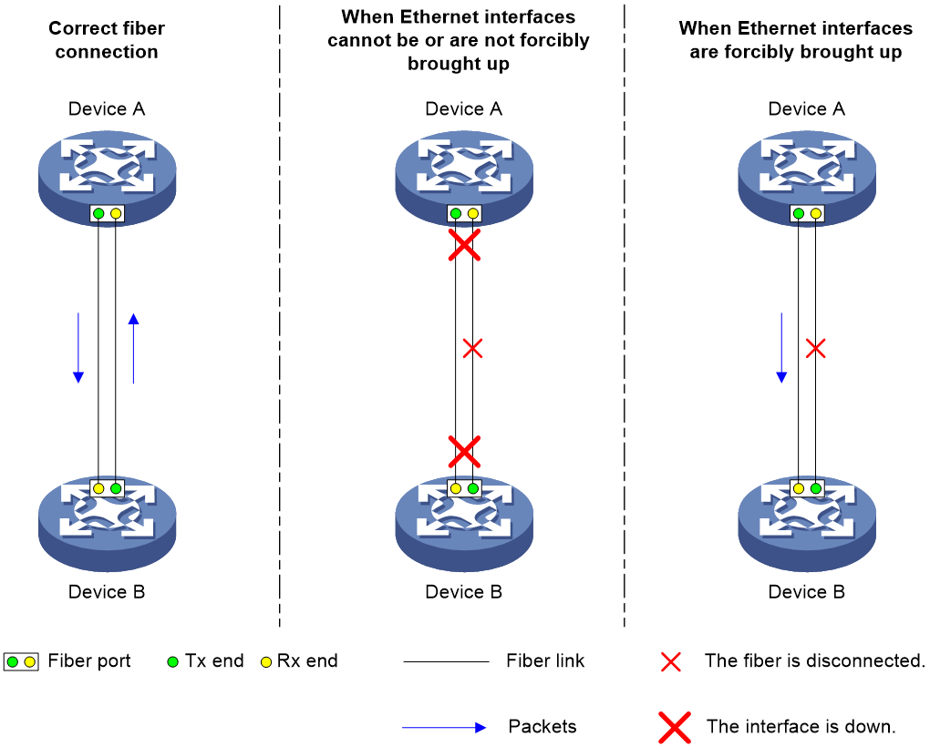
As shown in Figure 2, a fiber port uses separate fibers for transmitting and receiving packets. The physical state of the fiber port is up only when both transmit and receive fibers are physically connected. If one of the fibers is disconnected, the fiber port does not work.
To enable a fiber port to forward traffic over a single link, you can use the port up-mode command. This command forcibly brings up a fiber port, even when no fiber links or transceiver modules are present for the fiber port. When one fiber link is present and up, the fiber port can forward packets over the link unidirectionally.
Figure 2 Forcibly bring up a fiber port
Restrictions and guidelines
Only GE fiber ports and 10-GE fiber ports support this feature. Copper ports and combo interfaces do not support this feature.
The port up-mode, shutdown, and loopback commands are mutually exclusive.
A fiber port does not support this feature if the port is shut down by a protocol or by using the shutdown command.
A fiber port forcibly brought up stays physically up whether or not a transceiver module or a fiber link is present for the port.
A GE or 10-GE fiber port forcibly brought up cannot correctly forward traffic if it is installed with a fiber-to-copper converter, 100/1000-Mbps transceiver module, or 100-Mbps transceiver module. To solve the problem, use the undo port up-mode command on the fiber port.
Procedure
1. Enter system view.
system-view
2. Enter Ethernet interface view.
interface interface-type interface-number
3. Forcibly bring up the fiber port.
port up-mode
By default, a fiber port is not forcibly brought up, and the physical state of a fiber port depends on the physical state of the fibers.
Shutting down all physical interfaces
About this task
This feature allows you to shut down all physical interfaces except the management Ethernet interfaces on a device. Physical interfaces shut down by using this command are in ADM state. To bring one of these interfaces, execute the shutdown command on the interface.
Restrictions and guidelines
If you configure this feature in system view and execute the shutdown command in interface view multiple times, the most recent configuration takes effect.
Procedure
1. Enter system view.
system-view
2. Shut down all physical interfaces.
shutdown all-physical-interfaces
By default, physical interfaces are up.
Restoring the default settings for an interface
Restrictions and guidelines
|
|
CAUTION: This feature might interrupt ongoing network services. Make sure you are fully aware of the impacts of this feature when you use it in a live network. |
This feature might fail to restore the default settings for some commands because of command dependencies or system restrictions. You can use the display this command in interface view to check for these commands and perform their undo forms or follow the command reference to restore their default settings. If your restoration attempt still fails, follow the error message to resolve the problem.
Procedure
1. Enter system view.
system-view
2. Enter Ethernet interface view.
interface interface-type interface-number
3. Restore the default settings for the interface.
default
Configuring a Layer 2 Ethernet interface
Setting speed options for autonegotiation on an Ethernet interface
About this task
By default, speed autonegotiation enables an Ethernet interface to negotiate with its peer for the highest speed that both ends support. You can narrow down the speed option list for negotiation.
Figure 3 Speed autonegotiation application scenario
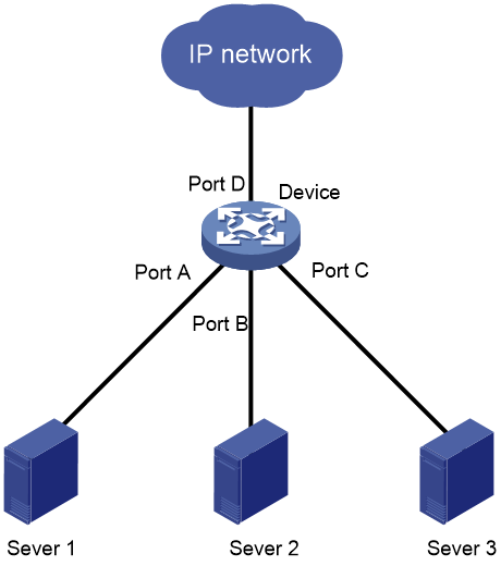
As shown in Figure 3:
· All interfaces on the device are operating in speed autonegotiation mode, with the highest speed of 1000 Mbps.
· Port D provides access to the Internet for the servers.
If the transmission rate of each server in the server cluster is 1000 Mbps, their total transmission rate exceeds the capability of Port D.
To avoid congestion on Port D, configure 100 Mbps as the only option available for speed negotiation on interfaces Port A, Port B, and Port C. As a result, the transmission rate on each interface connected to a server is limited to 100 Mbps.
Restrictions and guidelines
The speed and speed auto commands supersede each other, and whichever is configured last takes effect.
Procedure
1. Enter system view.
system-view
2. Enter Ethernet interface view.
interface interface-type interface-number
3. Set speed options for autonegotiation.
speed auto { 10 | 100 | 1000 } *
No speed options are set for autonegotiation.
Setting the MDIX mode of an Ethernet interface
|
|
IMPORTANT: Fiber ports do not support the MDIX mode setting. |
About this task
A physical Ethernet interface has eight pins, each of which plays a dedicated role. For example, pins 1 and 2 transmit signals, and pins 3 and 6 receive signals. You can use both crossover and straight-through Ethernet cables to connect copper Ethernet interfaces. To accommodate these types of cables, a copper Ethernet interface can operate in one of the following Medium Dependent Interface-Crossover (MDIX) modes:
· MDIX mode—Pins 1 and 2 are receive pins and pins 3 and 6 are transmit pins.
· MDI mode—Pins 1 and 2 are transmit pins and pins 3 and 6 are receive pins.
· AutoMDIX mode—The interface negotiates pin roles with its peer.
|
|
NOTE: This feature does not take effect on pins 4, 5, 7, and 8 of physical Ethernet interfaces. · Pins 4, 5, 7, and 8 of interfaces operating at 10 Mbps or 100 Mbps do not receive or transmit signals. · Pins 4, 5, 7, and 8 of interfaces operating at 1000 Mbps or higher rates receive and transmit signals. |
Restrictions and guidelines
To enable a copper Ethernet interface to communicate with its peer, set the MDIX mode of the interface by following these guidelines:
· Typically, set the MDIX mode of the interface to AutoMDIX. Set the MDIX mode of the interface to MDI or MDIX only when the device cannot determine the cable type.
· When a straight-through cable is used, configure the interface to operate in an MDIX mode different than its peer.
· When a crossover cable is used, perform one of the following tasks:
¡ Configure the interface to operate in the same MDIX mode as its peer.
¡ Configure either end to operate in AutoMDIX mode.
Procedure
1. Enter system view.
system-view
2. Enter Ethernet interface view.
interface interface-type interface-number
3. Set the MDIX mode of the Ethernet interface.
mdix-mode { automdix | mdi | mdix }
By default, a copper Ethernet interface operates in auto mode to negotiate pin roles with its peer.
Configuring storm control on an Ethernet interface
About this task
Storm control compares broadcast, multicast and unknown unicast traffic regularly with their respective traffic thresholds on an Ethernet interface. For each type of traffic, storm control provides a lower threshold and an upper threshold.
Depending on your configuration, when a particular type of traffic exceeds its upper threshold, the interface performs either of the following operations:
· Blocks this type of traffic and forwards other types of traffic—Even though the interface does not forward the blocked traffic, it still counts the traffic. When the blocked traffic drops below the lower threshold, the interface begins to forward the traffic.
· Goes down automatically—The interface goes down automatically and stops forwarding any traffic. When the blocked traffic drops below the lower threshold, the interface does not automatically come up. To bring up the interface, use the undo shutdown command or disable the storm control feature.
You can configure an Ethernet interface to output threshold event traps and log messages when monitored traffic meets one of the following conditions:
· Exceeds the upper threshold.
· Drops below the lower threshold.
Both storm suppression and storm control can suppress storms on an interface. Storm suppression uses the chip to suppress traffic. Storm suppression has less impact on the device performance than storm control, which uses software to suppress traffic. For more information about storm suppression, see "Configuring storm suppression."
Storm control uses a complete polling cycle to collect traffic data, and analyzes the data in the next cycle. An interface takes one to two polling intervals to take a storm control action.
Restrictions and guidelines
For the traffic suppression result to be determined, do not configure storm control together with storm suppression for the same type of traffic.
Procedure
1. Enter system view.
system-view
2. (Optional.) Set the statistics polling interval of the storm control module.
storm-constrain interval interval
The default setting is 10 seconds.
For network stability, use the default or set a longer statistics polling interval.
3. Enter Ethernet interface view.
interface interface-type interface-number
4. Enable storm control, and set the lower and upper thresholds for broadcast, multicast, or unknown unicast traffic.
storm-constrain { broadcast | multicast | unicast } { pps | kbps | ratio } upperlimit lowerlimit
By default, storm control is disabled.
5. Set the control action to take when monitored traffic exceeds the upper threshold.
storm-constrain control { block | shutdown }
By default, storm control is disabled.
6. Enable the Ethernet interface to output log messages when it detects storm control threshold events.
storm-constrain enable log
By default, the Ethernet interface outputs log messages when monitored traffic exceeds the upper threshold or drops below the lower threshold from a value above the upper threshold.
7. Enable the Ethernet interface to send storm control threshold event traps.
storm-constrain enable trap
By default, the Ethernet interface sends traps when monitored traffic exceeds the upper threshold or drops below the lower threshold from the upper threshold from a value above the upper threshold.
Testing the cable connection of an Ethernet interface
|
|
IMPORTANT: If the link of an Ethernet interface is up, testing its cable connection will cause the link to go down and then come up. |
About this task
The virtual cable test (VCT) technology uses time domain reflectometry (TDR) to detect the cable status. When pulse signals are transmitted in a cable, some energy of the signals is reflected at the end or a failure point on the cable. This phenomenon is called TDR. The VCT algorithm measures the time spent in transmitting pulse signals over a cable, reaching the failure point, and returning the pulse signals. The measured time is converted into the distance.
As shown in Figure 4, GE 1/0/1 on Device A is connected to GE 1/0/1 on Device B through a cable. A failure point exists on the cable. After VCT is configured on GE 1/0/1 on Device A, the system will generate pulse signals. Some energy of the signals is reflected at the failure point on the cable. Suppose the distance from Device A to the failure point is L, the interval between sending signals and receiving reflected signals is T, and the signal transmission speed on the cable is V. Then, the distance between GE 1/0/1 on Device A and the failure point can be calculated as follows: L=(V×T)/2.
Figure 4 Schematic diagram for VCT
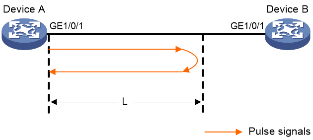
VCT detects the network cable failure type and identifies the failure point, facilitating failure location on network cables.
Restrictions and guidelines
Fiber ports do not support this feature.
Procedure
1. Enter system view.
system-view
2. Enter Ethernet interface view.
interface interface-type interface-number
3. Perform a test for the cable connected to the Ethernet interface.
virtual-cable-test
Enabling bridging on an Ethernet interface
About this task
By default, the device drops packets whose outgoing interface and incoming interface are the same.
To enable the device to forward such packets rather than drop them, enable the bridging feature in Ethernet interface view.
Procedure
1. Enter system view.
system-view
2. Enter Ethernet interface view.
interface interface-type interface-number
3. Enable bridging on the Ethernet interface.
port bridge enable
By default, bridging is disabled on an Ethernet interface.
Display and maintenance commands for Ethernet interfaces
For more information about the display diagnostic-information command, see device management in Fundamentals Command Reference.
|
|
NOTE: The display link-flap protection command is supported only in R1107 and later. |
Execute display commands in any view and reset commands in user view.
|
Task |
Command |
|
Display interface traffic statistics. |
display counters { inbound | outbound } interface [ interface-type [ interface-number ] ] |
|
Display traffic rate statistics of interfaces in up state over the last statistics polling interval. |
display counters rate { inbound | outbound } interface [ interface-type [ interface-number ] ] |
|
Display the operating information for the IFMGR module. |
display diagnostic-information ifmgr [ key-info ] [ filename ] |
|
Display the Ethernet module statistics. |
display ethernet statistics slot slot-number |
|
Display the operational and status information of the specified interfaces. |
display interface [ interface-type [ interface-number ] ] [ brief [ description | down ] ] |
|
Display the status and packet statistics of interfaces. |
display interface link-info |
|
Display information about link flapping protection on interfaces. |
display link-flap protection [ interface interface-type [ interface-number ] ] |
|
Display information about storm control on the specified interfaces. |
display storm-constrain [ broadcast | multicast | unicast ] [ interface interface-type interface-number ] |
|
Clear interface statistics. |
reset counters interface [ interface-type [ interface-number ] ] |
|
Clear the Ethernet module statistics. |
reset ethernet statistics [ slot slot-number ] |
