- Table of Contents
-
- 02-Typical configuration example
- 01-AAA_Configuration_Examples
- 02-ACL_Configuration_Examples
- 03-IGMP_Configuration_Examples
- 04-IP_Source_Guard_Configuration_Examples
- 05-Ethernet_OAM_Configuration_Examples
- 06-NQA_Configuration_Examples
- 07-QinQ_Configuration_Examples
- 08-OSPF_Configuration_Examples
- 09-MPLS_TE_Configuration_Examples
- 10-OpenFlow_Configuration_Examples
- 11-NAT_Configuration_Examples
- 12-RBAC_Configuration_Examples
- 13-POS_Interface_Configuration_Examples
- 14-CPOS_Interface_Configuration_Examples
- 15-DLDP_Configuration_Examples
- 16-IS-IS_Configuration_Examples
- 17-MPLS_L3VPN_Configuration_Examples
- 18-SSH_Configuration_Examples
- 19-Login_Management_Configuration_Examples
- 20-SNMP_Configuration_Examples
- 21-Priority_Marking_and_Queue_Scheduling_Configuration_Examples
- 22-Multicast_VPN_Configuration_Examples
- 23-BGP_Configuration_Examples
- 24-HoVPN_Configuration_Examples
- 25-L2TP_Configuration_Examples
- 26-VRRP_Configuration_Examples
- 27-Traffic_Filtering_Configuration_Examples
- 28-Samplers_and_IPv4_NetStream_Configuration_Examples
- 29-Software_Upgrade_Examples
- 30-MPLS_L2VPN_Configuration_Examples
- 31-NetStream_Configuration_Examples
- 32-Policy-Based_Routing_Configuration_Examples
- 33-Traffic_Policing_Configuration_Examples
- 34-BFD_Configuration_Examples
- 35-OSPFv3_Configuration_Examples
- 36-VPLS_Configuration_Examples
- 37-GTS_and_Rate_Limiting_Configuration_Examples
- 38-IPv6_IS-IS_Configuration_Examples
- 39-MPLS OAM_Configuration_Examples
- 40-BGP_Route_Selection_Configuration_Examples
- 41-IS-IS_Route_Summarization_Configuration_Examples
- 42-Attack_Protection_Configuration_Examples
- Related Documents
-
| Title | Size | Download |
|---|---|---|
| 14-CPOS_Interface_Configuration_Examples | 96.28 KB |
Introduction
This document provides CPOS-E1 channel configuration examples.
Prerequisites
The configuration examples in this document were created and verified in a lab environment, and all the devices were started with the factory default configuration. When you are working on a live network, make sure you understand the potential impact of every command on your network.
This document assumes that you have basic knowledge of CPOS interface, E1, and MP.
Example: Configuring CPOS-E1 channels
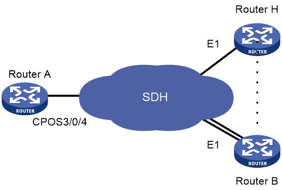
Network configuration
As shown in Figure 1, branch nodes Router B through Router H are uplinked to the central node Router A through E1 links. Router A aggregates these E1 links by using a CPOS interface.
Add one additional E1 link on Router B to expand its capacity, and use an MP-group interface to bind the two E1 links.
Restrictions and guidelines
For correct network synchronization, make sure the master clock mode is configured on the SONET/SDH devices connected to the routers.
Procedures
Configuring Router A
# Configure E1 channels 1 and 2 of CPOS 3/0/4 to operate in unframed mode.
[RouterA] controller cpos 3/0/4
[RouterA-Cpos3/0/4] e1 1 unframed
[RouterA-Cpos3/0/4] e1 2 unframed
# Create MP-group 3/0/1 and assign an IP address to it.
[RouterA] interface mp-group 3/0/1
[RouterA-Mp-group3/0/1] ip address 10.1.1.1 24
[RouterA-Mp-group3/0/1] quit
# Assign Serial 3/0/4/1:0 to MP-group interface 3/0/1.
[RouterA] interface serial3/0/4/1:0
[RouterA-Serial3/0/4/1:0] ppp mp mp-group 3/0/1
[RouterA-Serial3/0/4/1:0] quit
# Assign Serial 3/0/4/2:0 to MP-group interface 3/0/1.
[RouterA] interface serial3/0/4/2:0
[RouterA-Serial3/0/4/2:0] ppp mp mp-group 3/0/1
[RouterA-Serial3/0/4/2:0] quit
Configuring Router B
# Configure E1 3/0/10 to operate in E1 mode.
<RouterB> system-view
[RouterB] controller e1 3/0/10
[RouterB-E1 3/0/10] using e1
[RouterB-E1 3/0/10] quit
# Configure E1 3/0/8 to operate in E1 mode.
[RouterB] controller e1 3/0/8
[RouterB-E1 3/0/8] using e1
[RouterB-E1 3/0/8] quit
# Create MP-group 3/0/1 and assign an IP address to it.
[RouterB] interface mp-group 3/0/1
[RouterB-Mp-group3/0/1] ip address 10.1.1.2 24
[RouterB-Mp-group3/0/1] quit
# Assign Serial 3/0/10:0 to MP-group interface 3/0/1.
[RouterB] interface serial3/0/10:0
[RouterB-Serial3/0/10:0] ppp mp mp-group 3/0/1
[RouterB-Serial3/0/10:0] quit
# Assign Serial 3/0/8:0 to MP-group interface 3/0/1.
[RouterB] interface serial3/0/8:0
[RouterB-Serial3/0/8:0] ppp mp mp-group 3/0/1
[RouterB-Serial3/0/8:0] quit
Verifying the configuration
1. Verify the MP interface configuration and state on Router A and Router B.
# Display detailed information about MP-group interface 3/0/1 on Router A.
[RouterA] display interface mp-group 3/0/1
MP-group3/0/1
Current state: UP
Line protocol state: UP
Description: MP-group3/0/1 Interface
Bandwidth: 1024kbps
Maximum transmit unit: 1500
Hold timer: 10 seconds, retry times: 5
Internet Address is 10.1.1.1/24 (primary)
Link layer protocol: PPP
LCP: opened, MP: opened, IPCP: opened, OSICP: opened, MPLSCP: opened, IPv6CP: op
ened
Physical: MP, baudrate: 1024000 bps
Last link flapping: Never
Last clearing of counters: Never
Last 5 seconds input rate: 14 bytes/sec, 112 bits/sec, 0 packets/sec
Last 5 seconds output rate: 14 bytes/sec, 112 bits/sec, 0 packets/sec
Input: 73 packets, 24764 bytes, 0 drops
Output: 62 packets, 24882 bytes, 0 drops
The output shows that the MP-group interface on Router A is up.
# Display detailed information about MP-group interface 3/0/1 on Router B.
[RouterB] display interface mp-group 3/0/1
MP-group3/0/1
Current state: UP
Line protocol state: UP
Description: MP-group3/0/1 Interface
Bandwidth: 1024kbps
Maximum transmit unit: 1500
Hold timer: 10 seconds, retry times: 5
Internet Address is 10.1.1.2/24 (primary)
Link layer protocol: PPP
LCP: opened, MP: opened, IPCP: opened, OSICP: opened, MPLSCP: opened, IPv6CP: opened
Physical: MP, baudrate: 1024000 bps
Last link flapping: Never
Last clearing of counters: Never
Last 10 seconds input rate: 374 bytes/sec, 2992 bits/sec, 1 packets/sec
Last 10 seconds output rate: 293 bytes/sec, 2344 bits/sec, 0 packets/sec
Input: 39 packets, 12301 bytes, 0 drops
Output: 37 packets, 11824 bytes, 0 drops
The output shows that the MP-group interface on Router B is up.
2. Verify that the MP-group interface configuration on Router A and Router B.
# Display MP information on MP-group interface 3/0/1 of Router A.
[RouterA] display ppp mp interface mp-group 3/0/1
Template: MP-group3/0/1
max-bind: 16, fragment: enabled, min-fragment: 128
Master link: MP-group3/0/1, Active members: 2, Bundle Multilink
Peer's endPoint descriptor: MP-group3/0/1
Sequence format: long (rcv)/long (sent)
Bundle Up Time: 2021/07/25 09:16:07:745
0 lost fragments, 0 reordered, 0 unassigned, 0 interleaved
Sequence: 0 (rcv)/0 (sent)
Active member channels: 16 members
Serial3/0/4/1:0 Up-Time:2021/07/25 09:16:07:747
Serial3/0/4/2:0 Up-Time:2021/07/25 09:16:07:746
The output shows that the MP-group interface has been correctly configured.
# Display MP information on MP-group interface 3/0/1 of Router B.
[RouterB] display ppp mp interface mp-group 3/0/1
Template: MP-group3/0/1
max-bind: 16, fragment: enabled, min-fragment: 128
Master link: MP-group3/0/1, Active members: 2, Bundle Multilink
Peer's endPoint descriptor: MP-group3/0/1
Sequence format: long (rcv)/long (sent)
Bundle Up Time: 2021/07/25 09:16:07:745
0 lost fragments, 0 reordered, 0 unassigned, 0 interleaved
Sequence: 0 (rcv)/0 (sent)
Active member channels: 16 members
Serial3/0/8:0 Up-Time:2014/07/25 09:16:07:747
Serial3/0/10:0 Up-Time:2014/07/25 09:16:07:746
The output shows that the MP-group interface has been correctly configured.
3. Verify that the MP-group interface on Router A and Router B can ping each other.
# Ping MP-group interface 3/0/1 on Router B from Router A.
Ping 10.1.1.2 (10.1.1.2): 56 data bytes, press CTRL_C to break
56 bytes from 10.1.1.2: icmp_seq=0 ttl=255 time=32.998 ms
56 bytes from 10.1.1.2: icmp_seq=1 ttl=255 time=27.632 ms
56 bytes from 10.1.1.2: icmp_seq=2 ttl=255 time=34.517 ms
56 bytes from 10.1.1.2: icmp_seq=3 ttl=255 time=45.058 ms
56 bytes from 10.1.1.2: icmp_seq=4 ttl=255 time=35.121 ms
--- Ping statistics for 10.1.1.2 ---
5 packet(s) transmitted, 5 packet(s) received, 0.0% packet loss
round-trip min/avg/max/std-dev = 27.632/35.065/45.058/5.651 ms
# Ping MP-group interface 3/0/1 on Router A from Router B.
[RouterB] ping 10.1.1.1
Ping 10.1.1.1 (10.1.1.1): 56 data bytes, press CTRL_C to break
56 bytes from 10.1.1.1: icmp_seq=0 ttl=255 time=27.877 ms
56 bytes from 10.1.1.1: icmp_seq=1 ttl=255 time=27.616 ms
56 bytes from 10.1.1.1: icmp_seq=2 ttl=255 time=42.308 ms
56 bytes from 10.1.1.1: icmp_seq=3 ttl=255 time=36.238 ms
56 bytes from 10.1.1.1: icmp_seq=4 ttl=255 time=71.639 ms
--- Ping statistics for 10.1.1.1 ---
5 packet(s) transmitted, 5 packet(s) received, 0.0% packet loss
round-trip min/avg/max/std-dev = 27.616/41.136/71.639/16.214 ms
The output shows that the MP-group interfaces on Router A and Router B can ping each other.
Configuration files
· Router A:
controller cpos 3/0/4
e1 1 unframed
e1 2 unframed
#
interface mp-group 3/0/1
ip address 10.1.1.1 24
#
interface serial3/0/4/1:0
ppp mp mp-group 3/0/1
#
interface serial3/0/4/2:0
ppp mp mp-group 3/0/1
#
· Router B:
#
controller e1 3/0/10
using e1
#
controller e1 3/0/8
using e1
#
interface mp-group 3/0/1
ip address 10.1.1.2 24
#
interface serial3/0/8:0
ppp mp mp-group 3/0/1
#
interface serial3/0/10:0
ppp mp mp-group 3/0/1
#
Related documentation
· H3C CR16000-M Routers Interface Configuration Guide-R8385P09
· H3C CR16000-M Routers Interface Command Reference-R8385P09
· H3C CR16000-M Routers Layer 2—WAN Access Configuration Guide-R8385P09
· H3C CR16000-M Routers Layer 2—WAN Access Command Reference-R8385P09
