- Table of Contents
-
- 17-BRAS Services Configuration Guide
- 00-Preface
- 01-AAA configuration
- 02-ANCP configuration
- 03-PPP configuration
- 04-Value-added services configuration
- 05-DHCP configuration
- 06-DHCPv6 configuration
- 07-User profile configuration
- 08-Connection limit configuration
- 09-L2TP configuration
- 10-PPPoE configuration
- 11-IPoE configuration
- 12-802.1X configuration
- 13-UCM configuration
- Related Documents
-
| Title | Size | Download |
|---|---|---|
| 11-IPoE configuration | 4.54 MB |
Contents
IPoE access procedure by using bind authentication in common mode
IPoE access procedure by using Web authentication in common mode
IPoE quick Web authentication in common mode
IPoE 802.1X authentication user access procedure in common mode
IPoE access procedure by using bind authentication in CUPS mode
IPoE access procedure by using Web authentication in CUPS mode
IPoE quick Web authentication in CUPS mode
Support for EAP authentication
Restrictions and guidelines: IPoE configuration
IPoE bind authentication user tasks at a glance in common mode
IPoE Web authentication individual user tasks at a glance in common mode
IPoE 802.1X authentication access user tasks at a glance in common mode
IPoE bind authentication user tasks at a glance in CUPS mode
IPoE Web authentication user tasks at a glance in CUPS mode
Configuring the device to operate in user plane mode
Configuring CP-UP connection management
Configuring the remote portal authentication server
Specifying the HTTPS redirect listening port number
Obtaining user access information from ARP or ND entries
Enabling IPoE and setting the IPoE access mode
Configuring the authentication method
Configuring dynamic individual users
Dynamic individual user tasks at a glance
Configuring a dynamic individual session initiation method
Configuring authentication user naming conventions for dynamic individual users
Configuring passwords for dynamic individual users
Configuring ISP domains for dynamic individual users
Setting the dynamic individual session limit
Configuring trusted DHCP options for DHCP users
Configuring the parsing format for the circuit ID and remote ID in the DHCP option
Configuring trusted ISP domains for DHCP users
Configuring domain name generation rules for dynamic IPoE DHCP users
Allowing abnormally logged out IPoE users to come online again through packet initiation
Allowing DHCP users to access in loose mode
Configuring automatic IPoE user backup
Allowing users to come online through ND RS only after they come online through IA_PD
Configuring a static session initiation method
Configuring static individual sessions
Configuring static leased sessions
Configuring authentication user naming conventions for static users
Configuring passwords for static users
Configuring ISP domains for static users
Configuring session conflict detection
Configuring an interface-leased user
Configuring subnet-leased users
Configuring an L2VPN-leased user
Configuring ISP domains for leased users
Configuring Web authentication advanced features
Web authentication advanced feature tasks at a glance
Configuring an ISP domain for Web authentication individual users
Configuring HTTP packet fast reply
Configuring an SSL server policy for HTTPS redirection
Configuring the captive-bypass feature
Configuring Web authentication fail-permit
Configure the URL allowlist for Web authentication
Configuring IPoE web support for HTTP/HTTPS attack defense
Configuring IPoE quick Web authentication
Configuring transparent MAC-trigger authentication
Configuring transparent MAC authentication
Configuring the advanced 802.1X authentication features
Configuring the static 802.1X user authentication feature
Forcibly logging out an 802.1X client
Forcibly logging out an IPoE user when the 802.1X client goes offline
Setting the maximum number of individual sessions and leased subuser sessions on an interface
Configuring service-specific ISP domains
Configuring the quiet feature for users
Configuring online detection for IPoE users
Configuring NAS-Port-ID formats
Configuring NAS-Port-ID binding for IPoE access users
Enabling IPoE access-out authentication
Enabling roaming for IPoE individual users
Setting the response delay time for IPoE users
Configuring IPoE user access management
Configuring trusted IP addresses for IPoE authentication
Forbidding IPoE users from coming online
Configuring re-authentication for IPoE users
Display and maintenance commands for IPoE
IPoE configuration examples(on unified network)
Example: Configuring unclassified-IP packet initiation
Example: Configuring DHCPv4 packet initiation (assigning a remote BAS IP address pool)
Example: Configuring DHCPv4 packet initiation (assigning an IP address pool group)
Example: Configuring DHCPv6 packet initiation (assigning a remote IPv6 address pool)
Example: Configuring IPv6 ND RS packet initiation (AAA-authorized prefix)
Example: Configuring IPv6 ND RS packet initiation (ND prefix pool-authorized prefix)
Example: Configuring IPv6 ND RS+DHCPv6 (IA_PD) initiation
Example: Configuring ARP packet initiation
Example: Configuring NS/NA packet initiation
Example: Configuring unclassified-IP packet initiation for static IPoE users with IPv6 PD prefixes
Example: Configuring subnet-leased users
Example: Configuring an interface-leased user
Example: Configuring an L2VPN-leased user
Example: Configuring IPoE static leased users
Example: Configuring a VPN DHCP user
Example: Configuring IPoE common Web authentication for static individual users
Example: Configuring IPoE transparent MAC-trigger authentication (Layer 2 transparent)
Example: Configuring IPoE common transparent MAC authentication (Layer 2 transparent)
Example: Configuring IPoE re-DHCP transparent MAC authentication (Layer 2 transparent)
Example: Configuring IPoE transparent MAC-trigger authentication (Layer 3 transparent)
Example: Configuring IPoE transparent MAC authentication (Layer 3 transparent)
Example: Configuring IPoE Web authentication with EAP
Example: Configuring IPoE 802.1X authentication
Example: Configuring IPoE common Web authentication for dual-stack users (URL allowlist)
Example: Configuring IPoE common transparent MAC authentication for dual-stack users
Example: Configuring a dual-stack DHCP user
Example: Configuring a dynamic/static dual-stack user
Example: Configuring an IPoE DHCPv4+IPv6 ND RS dual-stack roaming user
IPoE configuration examples(on CUPS network)
Example: Configuring unclassified-IP packet initiation
Example: Configuring DHCPv4 packet initiation (assigning a local ODAP IP address pool)
Example: Configuring DHCPv4 packet initiation (assigning a remote BAS IP address pool)
Example: Configuring DHCPv4 packet initiation (assigning an IP address pool group)
Example: Configuring DHCPv6 packet initiation (assigning a local ODAP IPv6 address pool)
Example: Configuring DHCPv6 packet initiation (assigning a remote BAS IPv6 address pool)
Example: Configuring a dual-stack user (assigning remote BAS IP and IPv6 address pools)
Example: Configuring IPv6 ND RS packet initiation (AAA-authorized prefix)
Example: Configuring IPv6 ND RS packet initiation (ND prefix pool-authorized prefix)
Example: Configuring IPv6 ND RS+DHCPv6 (IA_PD) initiation
Example: Configuring ARP packet initiation
Example: Configuring NS/NA packet initiation
Example: Configuring unclassified-IP packet initiation for static IPoE users with IPv6 PD prefixes
Example: Configuring subnet-leased users
Example: Configuring an interface-leased user
Example: Configuring IPoE common Web authentication for static individual users
Example: Configuring IPoE transparent MAC-trigger authentication (Layer 2 transparent)
Example: Configuring IPoE common transparent MAC authentication (Layer 2 transparent)
Example: Configuring IPoE common transparent MAC authentication for dual-stack users
Example: Configuring unclassified-IP packet initiation for global IPoE users (UP backup)
Example: Configuring unclassified-IP packet initiation (VSI interface)
Configuring portal authentication
Restrictions and guidelines: Portal configuration
Portal authentication tasks at a glance
Configuring a remote portal authentication server
Configuring local portal service features
About the local portal service
Restrictions and guidelines for configuring local portal service features
Customizing authentication pages
Configuring a local portal Web service
Configuring portal detection features
Configuring portal authentication server detection
Configuring portal user synchronization
Configuring portal packet attributes
Configuring the BAS-IP or BAS-IPv6 attribute
Excluding an attribute from portal protocol packets
Configuring MAC-based quick portal authentication
Restrictions and guidelines for configuring MAC-based quick portal authentication
Configuring a MAC binding server
Specifying a MAC binding server on an interface
Obtaining user access information from ARP or ND entries
Display and maintenance commands for portal
Configuring IPoE
About IPoE
IP over Ethernet (IPoE) enables a broadband remote access server (BRAS) to connect and authenticate users over IPoE connections.
IPoE supports the following authentication methods:
· Bind authentication—The BRAS automatically generates usernames and passwords for users based on the user access location. Users are not required to enter usernames and passwords.
· Web authentication—The BRAS requires users to enter usernames and passwords on the Web authentication page.
· 802.1X authentication—The BRAS requires users to enter usernames and passwords on an 802.1X client. To access a Layer 3 interface through 802.1X, configure the 802.1X authentication method.
As shown in Figure 1, a BRAS connects hosts over IPoE connections, and provides AAA, security, DHCP, and portal services for the hosts. The host can be a browser running HTTP or HTTPS or a cellphone running the H3C iNode client.
Figure 1 IPoE network diagram
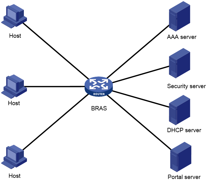
IPoE access modes
IPoE supports Layer 2 and Layer 3 access modes.
· Layer 2 access mode—Hosts directly access the BRAS. The hosts connect to the BRAS directly or through Layer 2 devices. The BRAS uses MAC addresses to identify the hosts.
· Layer 3 access mode—Hosts use routing to access the BRAS. The hosts connect to the BRAS directly or through Layer 3 devices. On a Layer 3 device between the hosts and BRAS, the source MAC address of packets received by the BRAS is the MAC address of the Layer 3 device. Therefore, the BRAS uses IP addresses or VLAN IDs to identify hosts.
IPoE CUPS mode
About this task
On a traditional BRAS, the control plane capabilities might not match the forwarding plane capabilities, the resources cannot be shared, and new services cannot be deployed in time. The vBRAS CP and UP separation (CUPS) solution is introduced to solve this problem.
In this solution, the forwarding plane and control plane are completely decoupled and are independent of each other. The solution contains control plane (CP) roles and user plane (UP) roles, which together implement the BRAS functionality.
· CP—Performs control plane services, including user identification and address allocation and management. Typically, a CP is a vBRAS.
· UP—Performs the forwarding plane services, including data packet forwarding and traffic control. A UP can be a router, or vBRAS.
The following three channels are established between the CP and UP to implement CUPS.
· Management channel—Deploys configuration between the CP and UP.
· Control channel—Deploys entries between the CP and UP.
· Protocol tunnel—Transmits protocol packets between the CP and UP.
Operating modes
In a CUPS network, a BRAS can operate in one of the following modes:
· Common mode—A BRAS operating in this mode performs both control and forwarding services. A device operating in this mode is called a unified device.
· Control plane mode—Also known as session mode. This mode implements the CP function based on remote interfaces. When the UP connected to a CP supports IPoE, you can configure the session mode. In this mode, the CP sends BRAS sessions to the UP. The UP performs data packet forwarding according to the received sessions. For more information about remote interfaces, see CP-UP connection management in the vBRAS-CP configuration guides.
· User plane mode—A BRAS operating in this mode performs only the forwarding service. A BRAS operating in user plane mode is a UP.
The control plane mode and user plane mode are collectively referred to as the CUPS mode.
|
|
NOTE: · Unless otherwise specified, a BRAS in this document operates in common mode. · In CUPS mode, this device can only act as a UP and cannot act as a CP. |
IPoE user types
IPoE sessions can be initiated by IP, ARP, NS, NA, ND RS, or DHCP packets. Depending on whether an IPoE user has independent service attributes, IPoE users include individual users and leased users.
Individual users
Individual users use independent IPoE services. The BRAS authenticates, authorizes, and accounts individual users based on user location and packet information. Individual users include dynamic and static individual users.
· Dynamic individual users
IPoE defines the following dynamic individual users:
¡ DHCP user—Sends DHCP packets to initiate IPoE sessions and obtains an IP address from the DHCP server.
¡ IPv6 ND RS user—Sends IPv6 ND RS packets to initiate IPoE sessions and obtains an IP address from the BRAS.
¡ Unclassified-IP user—Sends packets other than DHCP and IPv6 ND RS packets to initiate IPoE sessions.
· Static individual users
Static individual users initiate IPoE sessions by sending IP, ARP, NS, or NA packets. If an IP packet matches a manually configured IPoE session, the BRAS authenticates the user and establishes an IPoE session.
|
|
NOTE: A DHCP or IPv6 ND RS user is abnormally logged out if the IPoE session of the user is deleted for a reason except the user actively releases its IP address. With the function of allowing abnormally logged out IPoE users to come online again enabled, when the device receives IP, ARP, or NS/NA packets from the user, the device can restore the IPoE session for the user. The restored IPoE session is a DHCP or IPv6 ND RS session. For more information about re-logging in abnormally logged out IPoE users, see "Allowing abnormally logged out IPoE users to come online again through packet initiation." |
Leased users
Leased users include the following types:
· Interface-leased user—Represents hosts that rent the same interface.
· Subnet-leased user—Represents hosts that rent a subnet of an interface.
· L2VPN-leased user—Represents hosts that rent the same interface on an L2VPN network.
· Static leased user—A static leased user is a special type of leased line in the following aspects:
¡ Independent service attributes—Similar to an interface-leased line, unified authentication, authorization, and accounting are performed for all users on an interface. When a static leased session comes online, packets with any source IP address can pass through the leased interface.
¡ Packet initiation—Similar to a global static individual session, with IPoE enabled on an access interface in up state, when IP, ARP, NS, or NA packets pass through the access device, the access interface will try to initiate authentication by using the configured username and password. If a user passes authentication, a static leased session is established. If a user fails to pass authentication, no static leased session is established.
|
|
NOTE: Because static leased sessions are special, leased users include only interface-leased users, L2VPN-leased users, and subnet-leased users and do not include static leased users unless otherwise specified. |
IPoE session
An IPoE session represents all network connections of one IPoE client or a group of IPoE clients. An IPoE session can be identified by the IP packet characteristics or access location of clients. An IPoE session records the identification information, authentication status, authorization attributes, and DHCP address assignment information of IPoE clients.
Depending on the IPoE user types, IPoE sessions include individual sessions and leased sessions. .
Individual sessions
Depending on how a session is initiated, IPoE individual sessions include IPoE dynamic individual sessions and IPoE static individual sessions.
· IPoE dynamic individual session
IPoE sessions established for dynamic individual users are IPoE dynamic individual sessions.
The BRAS deletes a dynamic individual session in one of the following cases:
¡ The AAA-authorized session duration expires.
¡ The AAA server logs out the user.
¡ The user traffic is less than the AAA-authorized traffic during the idle-timeout time.
¡ The BRAS cannot detect the user after the number of detection attempts reaches the maximum.
- For a single-stack user, the session is deleted when the number of detection attempts reaches the maximum.
- For a dual-stack user, the session is deleted when the number of detection attempts reaches the maximum for both stacks.
¡ The IP address lease expires for IPoE sessions initiated by DHCP packets.
- For a single-stack user, the session is deleted when the IP address lease expires.
- For a dual-stack user, the session is deleted when the IP address leases of both stacks expire.
¡ The access interface goes down.
· IPoE static individual session
An IPoE static individual session represents all network connections of an IPoE client with the specified IP address (IPv6 or dual-stack global static sessions can contain IPv6 delegation prefixes). Typically, IPoE static individual sessions provide stable access services for clients with known IP addresses.
On an IPoE-enabled interface in up state, the BRAS initiates authentication based on the configured username and password upon receiving IP, ARP, NS, or NA packets from users. The BRAS creates a static individual session only when the authentication succeeds.
IPoE leased sessions
IPoE leased sessions are IPoE sessions established for IPoE leased users. IPoE leased sessions include the following types:
· Interface-leased session—Represents network connections of all IPoE clients on an interface.
· Subnet-leased session—Represents network connections of all IPoE clients in a subnet of an interface.
· L2VPN-leased session—Represents network connections of all IPoE client on an interface.
· Static leased session—Represents network connections of all IPoE clients on an interface.
For leased users, the BRAS initiates user authentication based on the configured username and password after you enable IPoE on an interface in up state. Authentication does not need to be initiated by user traffic. If the authentication succeeds, a leased session is established. If the authentication fails, no leased session is established.
A static leased session is a special type of leased line in the following aspects:
· Independent service attributes—Similar to an interface-leased line, unified authentication, authorization, and accounting are performed for all users on an interface. When a static leased session comes online, packets with any source IP address can pass through the leased interface.
· Packet initiation—Similar to a global static individual session, with IPoE enabled on an access interface in up state, when IP, ARP, NS, or NA packets pass through the access device, the access interface will try to initiate authentication by using the configured username and password. If a user passes authentication, a static leased session is established. If a user fails to pass authentication, no static leased session is established.
|
|
NOTE: Because static leased sessions are special, leased users include only interface-leased users, L2VPN-leased users, and subnet-leased users and do not include static leased users unless otherwise specified. |
IPoE addressing
IPoE addressing varies with user types.
A DHCP user obtains IP addresses in the following sequence:
1. Obtains an IP address from the AAA-authorized IP address pool.
2. Obtains an IP address from the IP address pool configured in the ISP domain if the AAA server does not authorize any IP address pools.
3. Obtains an IP address in the same network segment as the interface IP address if no IP address pool is configured in the ISP domain.
On an IPv6 network, a host can get an IPv6 global unicast address through the following methods:
· NDRA—The host obtains an IPv6 prefix in an RA message if the host sends RS packets to initiate authentication and successfully passes authentication. The host then generates an IPv6 global unicast address based on the IPv6 prefix. IPv6 prefixes include the following types in descending order of priority: AAA-authorized IPv6 prefix, prefix in the AAA-authorized ND prefix pool, RA prefix configured on an interface, and IPv6 global unicast address prefix configured on an interface. Among these prefixes:
¡ The following three prefix methods apply to the prefix sharing scenario: AAA-authorized IPv6 prefix, RA prefix configured on an interface, and IPv6 global unicast address prefix configured on an interface. In this scenario, multiple users share one IPv6 prefix.
¡ The AAA-authorized ND prefix pool or ND prefix pool group applies to the scenario of one prefix per user. In this scenario, each user has an exclusive IPv6 prefix.
· DHCPv6 (IA_NA)—The host requests an IPv6 global unicast address through DHCPv6. After an IPv6 address pool is authorized to users, IA_NA also supports authorizing the specified 128-bit IPv6 global unicast addresses to DHCP users through the following methods:
¡ Authorizing 128-bit IPv6 global unicast addresses by an AAA server through the Framed-IPv6-Address attribute.
¡ Authorizing 128-bit IPv6 global unicast addresses by using the authorization-attribute ipv6 command in local user view.
Make sure the 128-bit IPv6 global unicast addresses authorized by using the two methods above are within the authorized IPv6 address pool. Otherwise, the 128-bit IPv6 global unicast addresses authorized by using the two methods above are not used, and IPv6 addresses in the IPv6 address pool are randomly allocated to users.
· DHCPv6 (IA_PD)—A CPE requests prefixes through DHCPv6 and assigns them to downstream hosts. The hosts then use the prefixes to generate IPv6 global unicast addresses. This method uses the same principle of selecting address pools as the DHCPv6 (IA_NA) method.
You can configure the combination of NDRA+IA_PD or IA_NA+IA_PD methods as needed to meet the address allocation requirements in different scenarios.
If an ND prefix pool is used to allocate prefixes to users (in the one prefix per user scenario), the following restrictions apply to these users:
· These users cannot be leased users, including interface-leased users, subnet-leased users, and L2VPN-leased users.
· The ICMPv6 detection method is not supported.
· Prefixes of these users cannot be configured for static IPoE users.
· On an access interface of these users, you cannot configure an IPv6 global unicast address.
· On an access interface of an IPoE user exclusively using a prefix, you cannot configure an IPv6 global unicast address.
In DHCPv6 (IA_PD) method, you cannot configure an IPv6 global unicast address on the access interface of a user.
Other users use static IP addresses or obtain IP addresses from the DHCP server without using IPoE.
IPoE access procedure by using bind authentication in common mode
IPoE access by using bind authentication in common mode includes the following steps:
1. The BRAS initiates authentication.
The BRAS obtains information from user packets or IPoE sessions statically configured, and sends authentication requests.
2. The AAA server authenticates users.
The AAA server completes user authentication and sends the result to the BRAS. The security server, if configured, completes security authorization and sends the result to the BRAS.
3. (Optional.) DHCP allocates IP addresses and IPoE allocates IPv6 prefixes.
The DHCP server assigns an IP address to a DHCP user and the IPoE assigns an IPv6 prefix to an IPv6 ND RS user.
4. The BRAS performs access control.
The BRAS permits the user to get online and performs access control and accounting based on the authorized result.
Access procedure for DHCP single-stack users
This section uses a DHCPv4 user as an example to illustrate the access procedure for DHCP single-stack users. The BRAS acts as a DHCP relay agent.
Figure 2 Access procedure for a DHCPv4 user
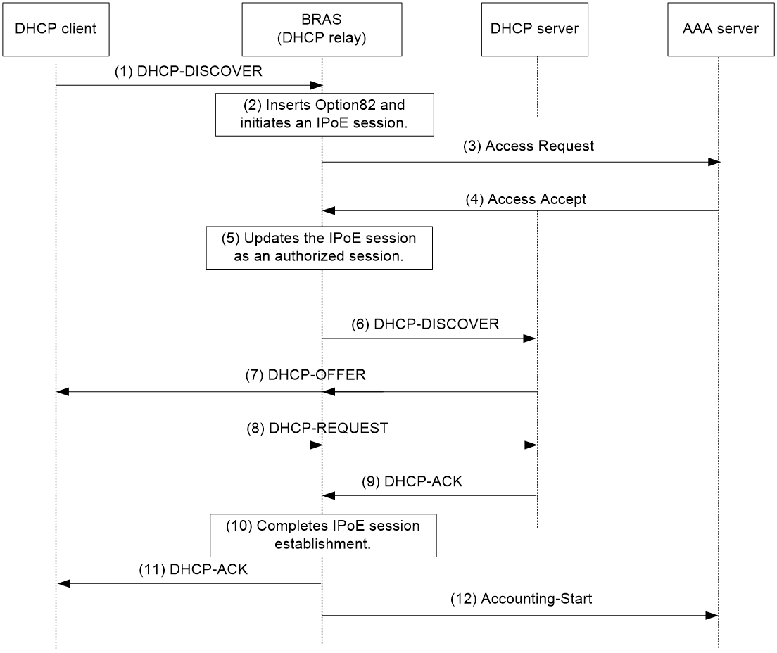
1. The DHCP client sends a DHCP-DISCOVER message to the BRAS.
2. The BRAS inserts Option 82 in the DHCP-DISCOVER message, and creates an IPoE session.
3. The BRAS sends the AAA server an access request that includes user information, such as the client ID and source MAC address.
4. The AAA server returns an Access-Accept packet that contains authorization information to the BRAS if the authentication succeeds. If the authentication fails, the AAA server returns an Access-Reject message.
5. The BRAS marks the IPoE session state as success and forwards the DHCP-DISCOVER message to the DHCP server if the authentication succeeds. If the authentication fails, the BRAS marks the session as failure and drops the DHCP-DISCOVER message.
6. The DHCP server sends a DHCP-OFFER message to the BRAS.
7. The BRAS forwards the DHCP-OFFER message to the DHCP client.
8. The DHCP client sends a DHCP-REQUEST message to the BRAS.
9. The BRAS forwards the DHCP-REQUEST message to the specified DHCP sever.
10. The DHCP server sends a DHCP-ACK message containing the assigned IP address to the BRAS.
11. The BRAS performs the following operations:
a. Obtains address information from the DHCP-ACK message.
b. Assigns a user profile.
c. Updates the IPoE session information.
d. Forwards the DHCP-ACK message to the client.
e. Marks the session state as online.
If the authentication fails, the BRAS marks the session as failure and drops the DHCP-DISCOVER message.
12. The DHCP client obtains configuration information from the DHCP-ACK message.
13. The BRAS sends the AAA server a message to start accounting.
Access procedure for DHCP dual-stack users
This section illustrates the access procedure for DHCP dual-stack users. The BRAS acts as a DHCP relay agent. DHCPv6 packet initiation include IA_NA and IA_PD methods. IA_NA assigns global unicast IPv6 addresses to hosts through DHCPv6. IA_PD assigns PD prefixes to clients through DHCPv6.
Figure 3 Access procedure for a DHCP dual-stack user
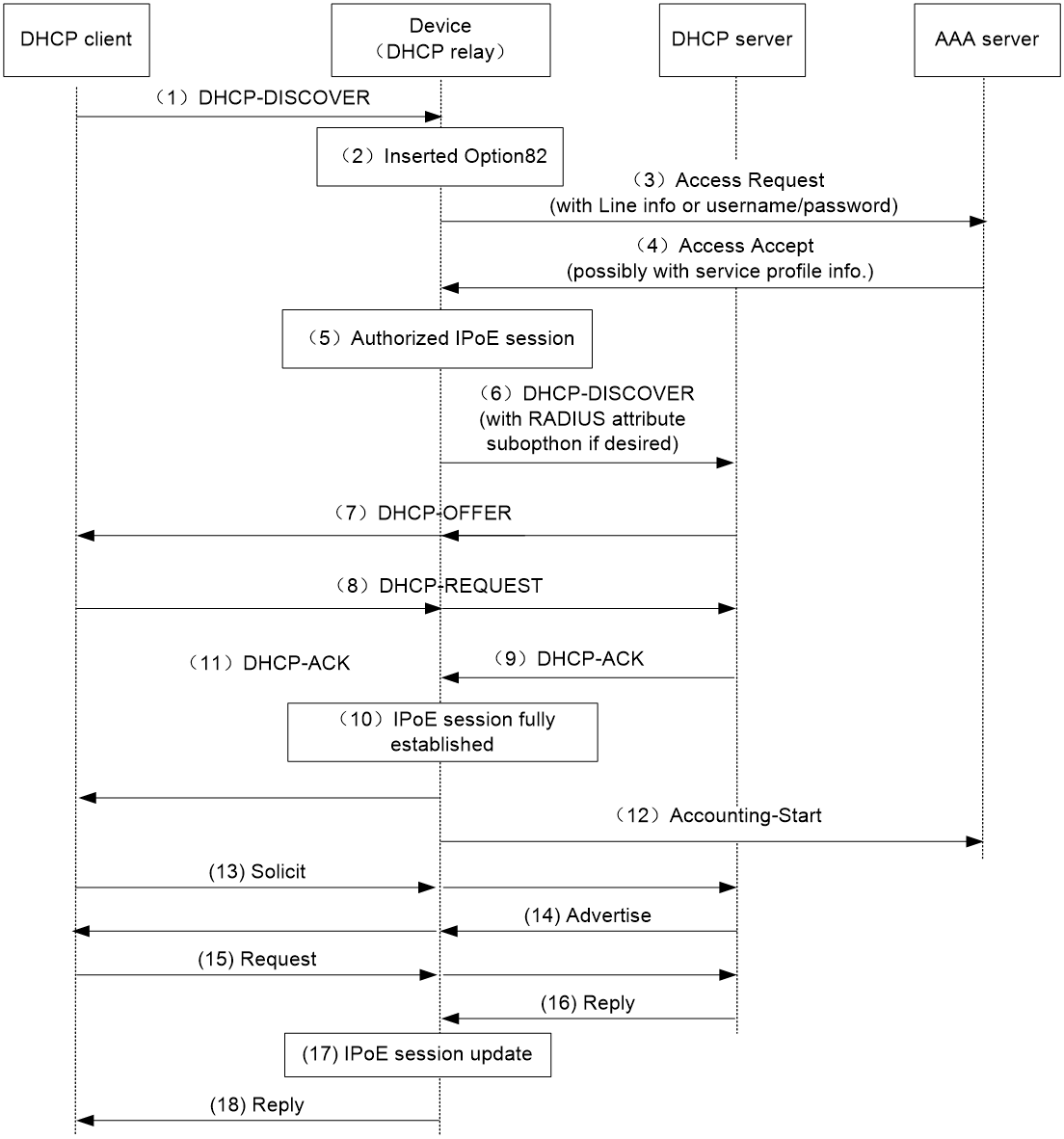
1. The DHCPv4 client sends a DHCP-DISCOVER message.
2. The DHCPv4 relay agent inserts Option 82 in the DHCP-DISCOVER message, and creates an IPoE session.
3. The relay agent sends the AAA server an access request including user information, such as the client ID and source MAC address in DHCPv4 packets.
4. The AAA server returns an Access-Accept packet that contains authorization information to the DHCPv4 relay agent if the authentication succeeds. If the authentication fails, the AAA server returns an Access-Reject message.
5. The DHCPv4 relay agent obtains the user authentication and authorization result, and updates the session status to success or failure.
6. The DHCPv4 relay agent forwards the DHCP-DISCOVER message to the DHCP server if the authentication succeeds. If the authentication fails, the DHCPv4 relay agent drops the DHCP-DISCOVER message.
7. The DHCPv4 server sends a DHCP-OFFER message to the DHCPv4 relay agent. The DHCPv4 relay agent forwards the DHCP-OFFER message to the DHCP client.
8. The DHCPv4 client sends a DHCP-REQUEST message to the DHCPv4 relay agent. The DHCPv4 relay agent forwards the DHCP-REQUEST message to the specified DHCP sever.
9. The DHCP server sends a DHCP-ACK message containing the assigned IP address to the DHCPv4 relay agent.
10. The DHCPv4 relay agent performs the following operations:
a. Obtains address information from the DHCP-ACK message.
b. Assigns a user profile.
c. Updates the IPoE session information.
d. Marks the session state as online.
11. The DHCPv4 relay agent forwards the DHCP-ACK message to the client. The DHCP client obtains configuration information from the DHCP-ACK message.
12. The DHCPv4 relay agent sends the AAA server a message to start accounting.
13. The DHCPv6 client sends a Solicit message. The DHCPv6 relay agent updates IPoE session information based on the Solicit message. The IA_NA field in packets corresponds to the obtained global unicast IPv6 address. The IA_PD field in packets corresponds to the obtained IPv6 address prefix.
14. The DHCPv6 server responds with an Advertise message. Then, the DHCPv6 relay agent forwards the Advertise message to the DHCPv6 client.
15. The DHCPv6 client select a DHCPv6 server according to the Advertise message and sends a request. The DHCPv6 relay agent forwards the request to the DHCPv6 server.
16. The DHCPv6 server responds with a reply message.
17. The DHCPv6 relay agent parses the IPv6 address, IPv6 address prefix, and other address parameters in the reply message, and updates the IPoE session.
18. The DHCPv6 relay agent forwards the reply message to the DHCPv6 client. The DHCPv6 client obtains the IPv6 address and related address parameters.
Access procedure for IPv6 ND RS users
This example uses a Layer 2 device as the BRAS.
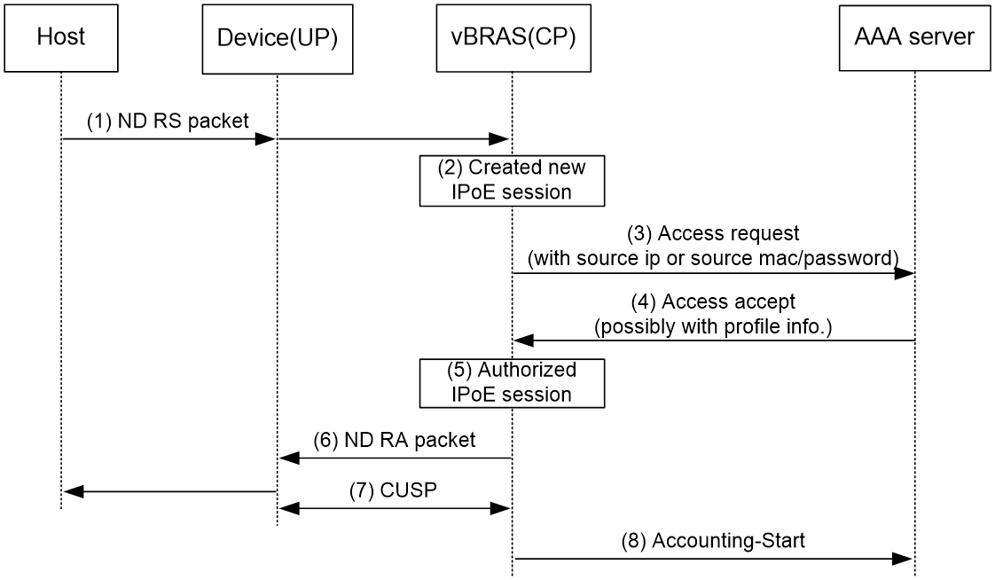
Figure 4 Access procedure for IPv6 ND RS users
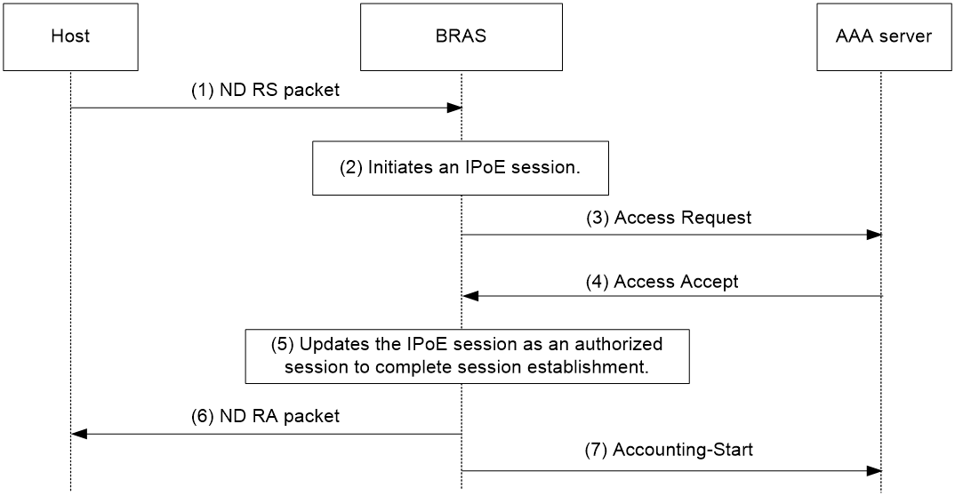
1. The host sends an IPv6 ND RS packet to the BRAS.
2. The BRAS initiates an IPoE session and sends the AAA server an access request that contains user information, such as the source MAC address.
3. The AAA server returns an Access-Accept packet that contains authorization information to the BRAS if the authentication succeeds. If the authentication fails, the AAA server returns an Access-Reject message.
4. The BRAS performs the following operations:
a. Generates an IPv6 address based on the host's MAC address and the IPv6 prefix.
b. Updates the IPoE session information.
c. Marks the session as success.
If the authentication fails, the BRAS marks the session as failure and drops the IPv6 ND RS packet.
5. The BRAS assigns a user profile and sends the host an IPv6 ND RA packet containing the IPv6 prefix.
6. The host generates an IPv6 address based on the received IPv6 prefix.
7. The BRAS sends the AAA server a message to start the service accounting.
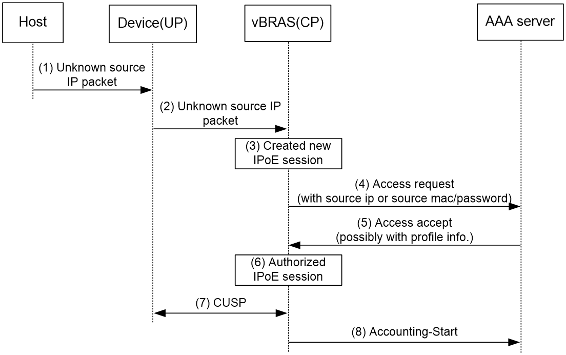
Access procedure for unclassified-IP users
Figure 5 Access procedure for unclassified-IP users
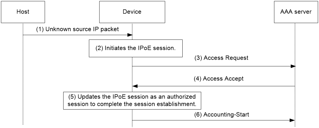
1. The host sends an IP packet to the BRAS.
2. The BRAS obtains user information from the IP packet, and compares the user information with existing IPoE sessions.
¡ If no match is found, the BRAS initiates an IPoE session for the user. (This section uses this case as an example.)
¡ If the information matches an authenticated session, the BRAS forwards the IP packet.
¡ If the information matches an unauthenticated session, the BRAS drops the IP packet.
3. The BRAS sends the AAA server an access request containing the obtained information, such as the source IP address or source MAC address.
4. The AAA server returns an Access-Accept packet that contains authorization information if the authentication succeeds. If the authentication fails, the AAA server returns an Access-Reject message.
5. The BRAS assigns a user profile and marks the IPoE session state as online.
6. The BRAS sends the AAA server a message to start the service accounting.
Access procedure for static and leased users
The access procedure for static users is the same as that for unclassified-IP users except in the following aspects:
· The IPoE static session is configured at the CLI.
· The IPoE static session can be initiated by IP, ARP, NS, or NA packets.
If you specify a global static user with an IPv6 delegation prefix, after the user comes online, the traffic matching the IPv6 delegation prefix network segment can also be directly forwarded.
The access procedure for leased users is the same as that for unclassified-IP users except in the following aspects:
· The IPoE leased session is configured at the CLI.
· The IPoE leased session does not need to be initiated by packets. Users are not required to send IP packets to trigger authentication. The BRAS initiates user authentication based on the configured username and password.
IPoE access procedure by using Web authentication in common mode
IPoE Web authentication applies to DHCP users, IPv6 ND RS users, and static individual users. The authentication process includes two phases: preauthentication and Web authentication (also known as postauthentication).
Preauthentication access procedure
The access procedure in the preauthentication phase is the same as the access procedure by using bind authentication for users in common mode. For more information about the access procedure, see "Access procedure for DHCP single-stack users," "Access procedure for IPv6 ND RS users," and "Access procedure for static and leased users."
Web authentication access procedure
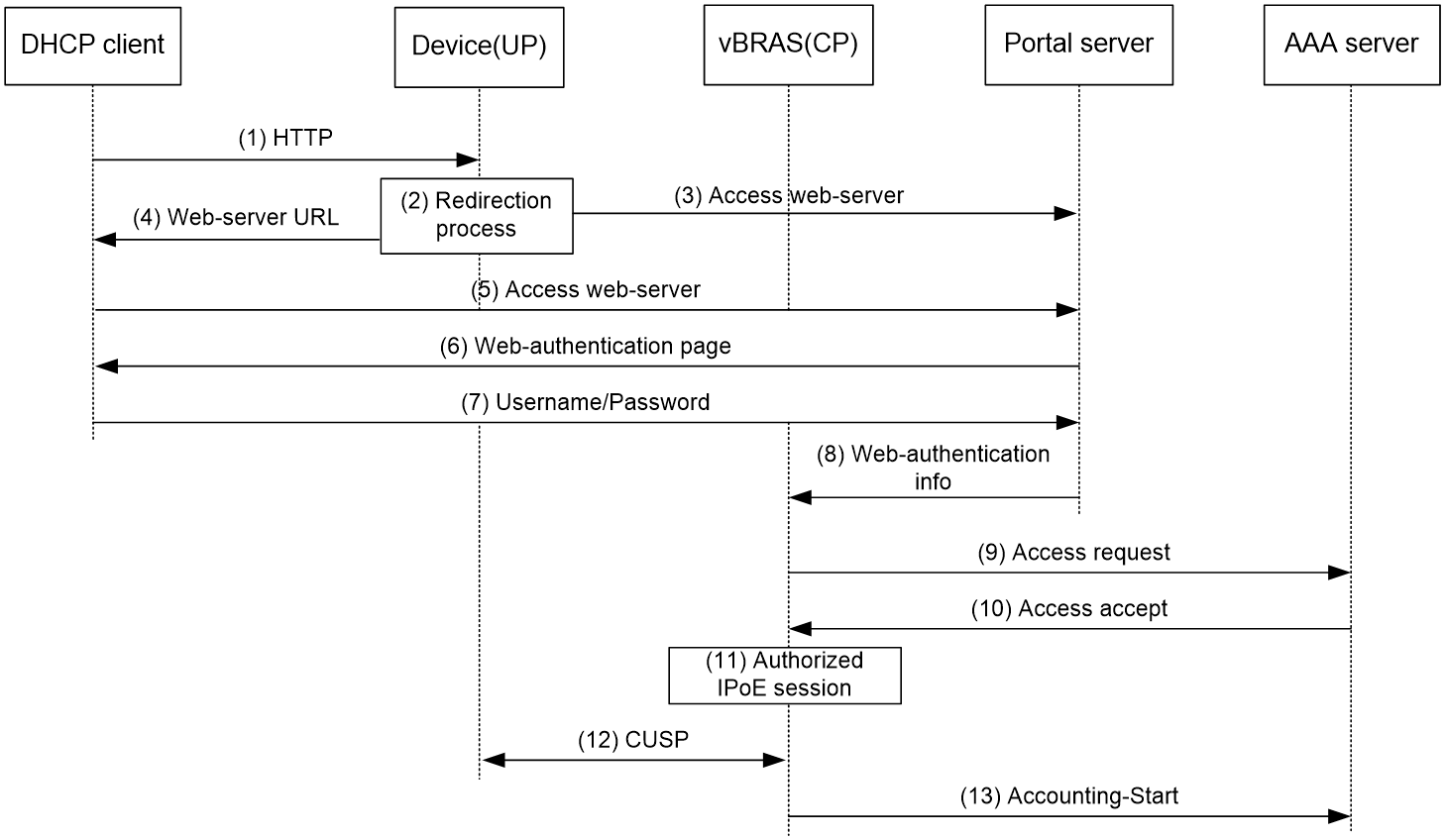
In the Web authentication phase, the authentication procedure is basically the same for users. This section uses a DHCPv4 user as an example to illustrate the access procedure by using Web authentication. The BRAS acts as a DHCP relay agent.
Figure 6 Web authentication access procedure
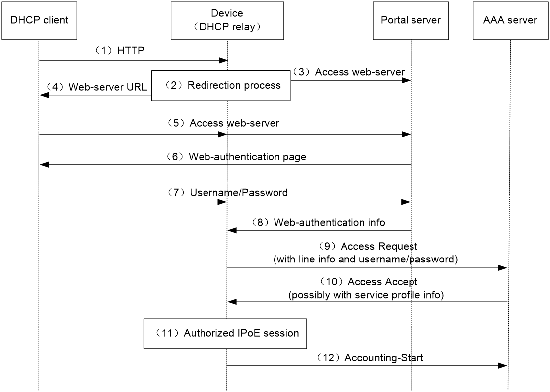
The user can perform Web authentication through the Web browser or the iNode client. This section uses the Web browser as an example.
1. The DHCP client initiates an HTTP/HTTPS GET message.
2. The BRAS checks the destination IP address of the HTTP/HTTPS GET message.
¡ If the message is destined for the portal Web server, the BRAS forwards the message to the portal Web server. The DHCP client directly accesses the Web authentication page of the portal Web server. .
¡ If the message is not destined for the portal Web server, the BRAS sends the message containing the Web server URL information to the DHCP client.
3. The DHCP client automatically accesses the redirected URL based on configured Web server URL information.
4. The portal Web server sends the Web authentication page to the DHCP client.
5. The user enters a username and password on the Web authentication page.
6. The portal server forwards the Web authentication information to the BRAS.
7. The BRAS sends the AAA server an access request based on the Web authentication information.
8. The AAA server returns to the BRAS one of the following results:
¡ An Access-Accept packet that contains authorization information if the authentication succeeds.
¡ An Access-Reject message if the authentication fails.
9. The BRAS performs one of the following operations based on the received result:
¡ Updates the IPoE session state as failed upon receiving an Access-Reject message.
¡ Updates the IPoE session state as authorized upon receiving an Access-Accept packet.
10. If the authentication succeeds, the BRAS sends the AAA server a message to start accounting.
|
|
NOTE: When the user performs Web authentication through the iNode client, the user can directly open the client authentication page and enter the authentication information. The remaining steps 6 through 10 are the same. |
IPoE quick Web authentication in common mode
In an IPoE Web environment, IPoE Web authentication supports quick authentication. With quick authentication, users that access the network frequently do not need to enter authentication information each time they come online in the Web authentication phase.
For valid users that access the network frequently, you can implement MAC-based quick authentication. It allows users to pass authentication without entering authentication information. MAC-based quick authentication is also called transparent authentication. Based on the location where the usernames, passwords, and MAC-to-account bindings of users are stored, transparent authentication includes the following types:
· Transparent MAC-trigger authentication—To use transparent MAC-trigger authentication, you must deploy a MAC binding server in the network. The MAC binding server records the MAC-to-account bindings of users for authentication.
· Transparent MAC authentication—To use transparent MAC authentication, you must deploy an AAA server that can bind the Web authentication information of users to MAC addresses of user endpoints for authentication.
Depending on the IP address allocation methods, transparent MAC authentication includes the following types:
¡ Common transparent MAC authentication—Only one IP address allocation is performed in the whole authentication and coming online process. A user triggers transparent MAC authentication in the Web authentication phase. After the user passes transparent MAC authentication, the user comes online in the Web authentication phase.
¡ Re-DHCP transparent MAC authentication—Two IP address allocations are performed in the whole authentication and coming online process. A user triggers transparent MAC authentication in the preauthentication phase. After the user passes transparent MAC authentication, the user comes online in the preauthentication phase.
When transparent MAC-trigger authentication or common transparent MAC authentication is configured, IPoE queries the MAC bindings for a user when receiving any IP packets of the user in the preauthentication domain. For a user that uses Web access for the first time, the authentication procedure includes the querying process.
When re-DHCP transparent MAC authentication is configured, IPoE triggers preauthentication and queries the MAC binding for a user when receiving DHCP-DISCOVER (IPv4) or Solicit (IPv6) packets.
Transparent MAC-trigger authentication procedure
|
|
IMPORTANT: Transparent MAC-trigger authentication supports only Web authentication that is triggered through the Web browser. |
1. The client initiates HTTP/HTTP requests after coming online in the preauthentication domain.
2. The BRAS checks the destination IP of the HTTP/HTTPS request.
3. If the message is destined for the portal Web server, the BRAS forwards the message to the portal Web server.
4. If the message is not destined for the portal Web server, the BRAS sends a binding query request to the portal server. The portal server returns the query result.
If the query result shows that the user has not been bound, the following operations are performed:
a. The BRAS redirects the subsequent HTTP/HTTPS requests to the Web authentication page of portal Web server. The BRAS sends HTTP/HTTPS messages containing the Web authentication page URL of the portal Web server to the client.
b. The client browser automatically accesses the Web authentication page of the portal Web server.
c. The portal Web server sends the Web authentication page contents to the client.
d. The user enters the username and password and click Log in to send the authentication information to the portal server.
If the query result shows that the user has been bound, the BRAS waits for the Web authentication information from the portal server.
5. The portal Web server sends the Web authentication information to the BRAS.
6. The BRAS sends the AAA server an access request based on the Web authentication information.
7. The AAA server returns to the BRAS one of the following results:
¡ An Access-Accept packet that contains the authorization information if the authentication succeeds.
¡ An Access-Reject message if the authentication fails.
8. The BRAS performs one of the following operations based on the received result:
¡ Updates the IPoE session state as failed upon receiving an Access-Reject message.
¡ Updates the IPoE session state as authorized upon receiving an Access-Accept packet.
9. If the authentication succeeds, the BRAS sends the AAA server a message to start accounting.
10. (Applicable only to users that perform Web authentication the first time.) After the user comes online, the BRAS notifies the portal server of the event. After receiving the notification, the portal server notifies the MAC binding server to add a MAC binding for the user.
When the user accesses the network the next time, the user can come online through quick authentication based on the queried MAC binding entry after the BRAS receives any IP packets of the user.
Common transparent MAC authentication procedure
|
|
IMPORTANT: Common transparent MAC authentication supports only Web authentication that is triggered through the Web browser. |
The common transparent MAC authentication procedure is as follows (take the first login as an example):
1. The client initiates HTTP/HTTP requests after coming online in the preauthentication domain.
2. The BRAS checks the destination IP of the HTTP/HTTPS request.
3. If the message is destined for the portal Web server, the BRAS forwards the message to the portal Web server.
4. If the message is not destined for the portal Web server, the BRAS uses the MAC address of the user as the username to send authentication requests to the AAA server. Because the user logs in for the first time, the AAA server fails to query the binding of the user based on the MAC address and returns authentication failure.
a. The BRAS redirects the subsequent HTTP/HTTPS requests to the Web authentication page of portal Web server.
b. The client browser automatically accesses the Web authentication page of the portal Web server.
c. The portal Web server sends the Web authentication page contents to the client.
d. The user enters the username and password and click Log in to send the authentication information to the portal server.
5. The portal Web server sends the Web authentication information to the BRAS.
6. The BRAS sends the AAA server an access request based on the Web authentication information.
7. The authentication succeeds. The AAA server returns to the BRAS an Access-Accept packet that contains the authorization information.
8. The BRAS updates the IPoE session state as authorized upon receiving an Access-Accept packet.
9. The authentication succeeds. The BRAS sends the AAA server a message to start accounting.
10. After the user comes online, the BRAS notifies the AAA server of the event. After receiving the notification, the AAA server adds a MAC binding for the user.
When the user accesses the network the next time, the BRAS uses the MAC address of the user as the username to send authentication requests to the AAA server after receiving any IP packets of the user. The AAA server can query the MAC binding for the user and returns authentication success. Then, the user can come online without entering the username and password.
Re-DHCP transparent MAC authentication procedure
|
|
IMPORTANT: · Re-DHCP transparent MAC authentication is only supported by DHCP users (including IPv4 and IPv6 users). For a dual-stack user to support re-DHCP transparent MAC authentication, make sure the user is a DHCP user in at least one protocol stack. · Re-DHCP transparent MAC authentication supports only Web authentication that is triggered through the Web browser. |
The re-DHCP transparent MAC authentication procedure is as follows (take the first login as an example):
1. When the device receives DHCP-DISCOVER (IPv4) or Solicit (IPv6) packets from a user, the device triggers preauthentication and uses the user MAC address as the username to initiate authentication on the AAA server. (In this phase, suppose ISP domain dm1 is used, which is configured by using the ip subscriber pre-auth domain command.)
2. Because the user logs in for the first time, the AAA server fails to query the binding of the user based on the MAC address and returns authentication failure. After the user fails authentication, the user uses the reauthentication domain dm2 to trigger preauthentication again. Domain dm2 is configured not to perform authentication by using the none keyword. The user comes online in the preauthentication domain and obtains a temporary IP address. (In this phase, suppose reauthentication domain dm2 is used, which is configured by using the authen-fail online domain command.)
3. After the user comes online in the preauthentication domain, the user initiates HTTP/HTTPS requests and comes online in the Web authentication phase through the common Web authentication process. Then, the AAA server adds a MAC binding entry for the user. (In this phase, suppose ISP domain dm3 is used, which is configured by using the ip subscriber web-auth domain command.)
4. After the device receives accounting response packets from the AAA server, the device clears session information for the DHCP user and forcibly logs out the user. For a dual-stack user, the user will be forcibly logged out in both stacks only if it is a DHCP user in one protocol stack. If the user wants to come online again, the user needs to trigger preauthentication again (if the user is not a DHCP user in a protocol stack, the user must come online again based on the original configuration). Later, if the device receives DHCP lease renewal requests from the user, the device directly replies with NAK, so that the user can come online as soon as possible through transparent MAC authentication in the preauthentication domain.
5. When the device receives DHCP-DISCOVER (IPv4) or Solicit (IPv6) packets from the user again, the device triggers preauthentication and uses the user MAC address as the username to initiate authentication on the AAA server. The AAA server queries the MAC binding for the user based on the user MAC address and returns authentication success packets carrying the authorization domain (dm4 in this example). The device allocates a public network IP address to the user according to the IP address pool in the authorization domain.
6. If the authentication success packets returned by the AAA server do not carry an authorization domain, authorize an IP address pool in authentication domain dm1. Then, the device allocates a public network IP address in the authorized IP address pool to the user.
IPoE 802.1X authentication user access procedure in common mode
|
|
NOTE: In the current software version, IPoE 802.1X authentication is supported only in common mode. |
IPoE 802.1X authentication supports DHCP users, IPv6 ND RS users, and static users. The authentication process includes two phases, including preauthentication and postauthentication. For a user configured with a static IP address to come online through 802.1X authentication without configuring the corresponding IPoE static user access on the BRAS, you can enable the static 802.1X user authentication feature. For more information, see the ip subscriber static-dot1x-user enable command.
When 802.1X authentication is not prioritized, an 802.1X user must perform IPoE preauthentication and 802.1X postauthentication to come online. When 802.1X authentication is prioritized, an 802.1X user only needs to perform one authentication on the 802.1X client. Select whether to prioritize 802.1X authentication as needed.
When 802.1X authentication is not prioritized, an IPoE comes online in the following process:
· In the preauthentication phase:
The user access procedure in the preauthentication phase is the same as the user access procedure in the bind authentication mode. This phase does not involve 802.1X authentication.
· In the postauthentication phase:
After an IPoE user comes online in the preauthentication domain, the system determines the processing method in the postauthentication domain according to the authentication result of the 802.1X client as follows:
¡ If the 802.1X client of the user is already online, IPoE uses the 802.1X authentication result to have the user come online directly in the postauthentication domain. In this case, the recorded user information is the 802.1X user information, including the 802.1X username, authentication domain, and authorized attributes.
¡ If the 802.1X client of the user is not online, the IPoE user stays in the preauthentication phase. When the 802.1X client of the user comes online, the processing is the same as that in the previous step.
¡ When both 802.1X authentication and Web authentication are configured on an interface, the following rules apply:
- If an IPoE user has come online in the postauthentication domain through Web authentication before the 802.1X client comes online, the device will force the user to return to the preauthentication domain from the postauthentication domain of Web authentication after the 802.1X client comes online, and then the user uses 802.1X authentication to come online in the postauthentication domain of 802.1X authentication.
- After an IPoE user uses 802.1X authentication to come online in the postauthentication domain, the user cannot use Web authentication to come online in the postauthentication domain.
When 802.1X authentication is prioritized, the following rules apply when an IPoE user tries to come online in the preauthentication phase:
· If the 802.1X client of the IPoE user is not online, the IPoE user will stay in the state before the preauthentication phase. After the 802.1X client of the user comes online, IPoE uses the 802.1X authentication result to have the user come online directly in the postauthentication domain. In this case, the recorded user information is the 802.1X user information, including the 802.1X username, authentication domain, and authorized attributes.
· If the 802.1X client of the IPoE user is already online, IPoE uses the 802.1X authentication result to have the user come online directly in the postauthentication domain. In this case, the recorded user information is the 802.1X user information, including the 802.1X username, authentication domain, and authorized attributes.
· If the 802.1X client of the IPoE user fails to pass authentication, the IPoE user continues to come online through the IPoE authentication process. In this case, the recorded user information is the IPoE user information, including the IPoE username, authentication domain, and authorized attributes.
IPoE access procedure by using bind authentication in CUPS mode
Access procedure for DHCP single-stack users
This section uses a DHCPv4 user as an example to illustrate the access procedure for DHCP single-stack users.
Figure 7 Access procedure for a DHCPv4 user
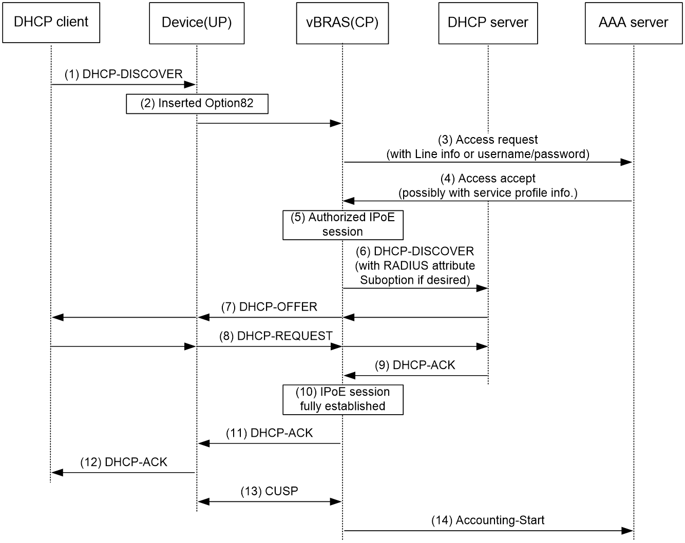
1. The DHCP client sends a DHCP-DISCOVER message to the UP.
2. The UP sends the message to the CP over the VXLAN tunnel.
3. The CP sends the AAA server an access request that includes user information, such as the client ID and source MAC address.
4. The AAA server returns an Access-Accept packet that contains authorization information to the CP if the authentication succeeds.
If the authentication fails, the AAA server returns an Access-Reject message.
5. The CP marks the IPoE session state as success and forwards the DHCP-DISCOVER message to the DHCP server if the authentication succeeds.
If the authentication fails, the CP marks the session as failure and drops the DHCP-DISCOVER message.
6. The DHCP server sends a DHCP-OFFER message to the CP.
7. The CP forwards the DHCP-OFFER message to the UP over the VXLAN tunnel. The UP forwards the DHCP-OFFER message to the DHCP client.
8. The DHCP client sends a DHCP-REQUEST message to the UP.
9. The UP forwards the DHCP-REQUEST message to the CP. The CP forwards the DHCP-REQUEST message to the specified DHCP sever.
10. The DHCP server sends a DHCP-ACK message containing the assigned IP address to the CP.
11. The CP performs the following operations:
a. Obtains address information from the DHCP-ACK message.
b. Assigns a user profile.
c. Updates the IPoE session information.
d. Marks the session state as online.
If the authentication fails, the CP marks the session as failure and drops the DHCP-DISCOVER message.
12. The CP forwards the DHCP-ACK message to the UP over the VXLAN tunnel.
13. The UP sends the DHCP-ACK message to the client.
14. The DHCP client obtains configuration information from the DHCP-ACK message.
15. The CP synchronizes the IPoE session information to the UP over the CUPS channel. The UP periodically collects traffic statistics, and sends the traffic statistics to the CP over the CUPS channel.
16. The CP sends the AAA server a message to start accounting.
Access procedure for DHCP dual-stack users
This section illustrate the access procedure for DHCP dual-stack users.
Figure 8 Access procedure for a DHCP dual-stack user
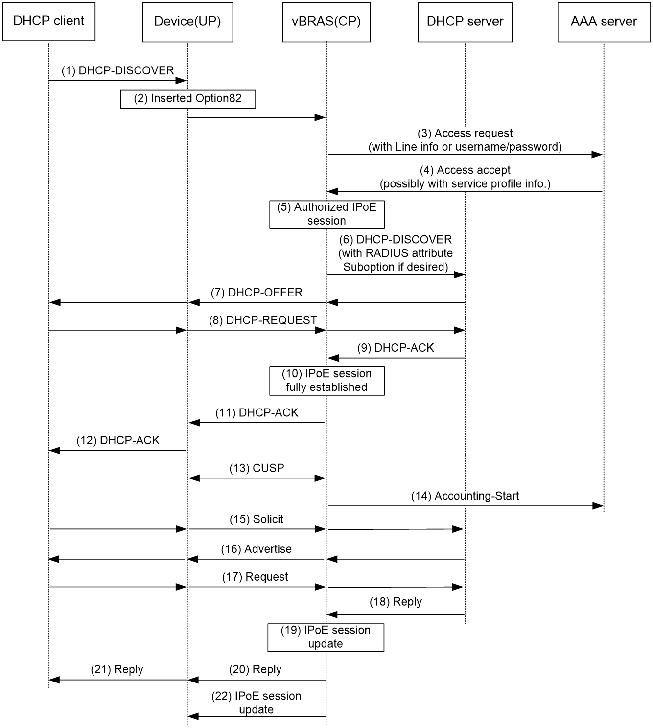
1. The DHCPv4 client sends a DHCP-DISCOVER message to the UP.
2. The UP sends the message to the CP over the VXLAN tunnel.
3. The CP creates an IPoE session. The CP sends the AAA server an access request that includes user information, such as the client ID and source MAC address in DHCP packets.
4. The AAA server returns an Access-Accept packet that contains authorization information to the CP if the authentication succeeds.
If the authentication fails, the AAA server returns an Access-Reject message.
5. The CP obtains the user authentication and authorization result, and updates the session status to success or failure.
6. The CP forwards the DHCP-DISCOVER message to the DHCP server if the authentication succeeds.
If the authentication fails, the CP drops the DHCP-DISCOVER message.
7. The DHCP server sends a DHCP-OFFER message to the CP. The CP forwards the DHCP-OFFER message to the UP over the VXLAN tunnel. The UP forwards packets to the DHCP client.
8. The DHCP client sends a DHCP-REQUEST message to the UP. The UP forwards the DHCP-REQUEST message to the CP. Then, the CP forwards the DHCP-REQUEST message to the specified DHCP sever.
9. The DHCP server sends a DHCP-ACK message containing the assigned IP address to the CP.
10. The CP performs the following operations:
a. Obtains address information from the DHCP-ACK message.
b. Assigns a user profile.
c. Updates the IPoE session information.
d. Marks the session state as online.
11. The CP forwards the DHCP-ACK message to the UP.
12. The UP forwards the DHCP-ACK message to the DHCP client. The DHCP client obtains configuration information from the DHCP-ACK message.
13. The CP synchronizes the IPoE session information to the UP over the CUPS channel. The UP periodically collects traffic statistics, and sends the traffic statistics to the CP over the CUPS channel.
14. The CP sends the AAA server a message to start accounting.
15. The DHCPv6 client sends a Solicit message to the UP. The UP forwards the message to the CP over the VXLAN tunnel. The CP updates IPoE session information based on the Solicit message.
16. The DHCPv6 server responds with an Advertise message. The CP forwards the Advertise message to the UP over the VXLAN tunnel. Then, the UP forwards the Advertise message to the DHCPv6 client.
17. The DHCPv6 client select a DHCPv6 server according to the Advertise message and sends a request to the UP. The UP forwards the request to the CP over the VXLAN tunnel. The CP forwards the request to the DHCPv6 server.
18. The DHCPv6 server responds with a reply message.
19. The CP parses the IPv6 address and other address parameters in the reply message, and updates the IPoE session.
20. The CP forwards the reply message to the UP. The UP forwards the reply message to the DHCPv6 client. The DHCPv6 client obtains the IPv6 address and related address parameters.
21. The CP synchronizes the IPoE sessions information to the UP through the CUPS channel.
Access procedure for IPv6 ND RS users
This example uses a Layer 2 device as the BRAS.
Figure 9 Access procedure for IPv6 ND RS users
1. The host sends an IPv6 ND RS packet to the UP. The UP sends the packet to the CP.
2. The CP initiates an IPoE session and sends the AAA server an access request that contains user information, such as the source MAC address.
3. The AAA server returns an Access-Accept packet that contains authorization information to the CP if the authentication succeeds.
If the authentication fails, the AAA server returns an Access-Reject message, and the CP marks the session as failure and drops the IPv6 ND RS packet.
4. The CP performs the following operations:
a. Generates an IPv6 address based on the host's MAC address and the IPv6 prefix.
b. Updates the IPoE session information.
c. Marks the session as success.
5. The CP sends the UP an IPv6 ND RA packet containing the IPv6 prefix. The UP sends the IPv6 ND RA packet to the host.
6. The host generates an IPv6 address based on the received IPv6 prefix.
7. The CP synchronizes the IPoE session information to the UP over the CUPS channel. The UP periodically collects traffic statistics, and sends the traffic statistics to the CP over the CUPS channel.
8. The CP sends the AAA server a message to start the service accounting.
Access procedure for unclassified-IP users
Figure 10 Access procedure for unclassified-IP users
1. The host sends an IP packet to the UP.
2. The UP obtains user information from the IP packet, and compares the user information with existing IPoE sessions.
¡ If no match is found, the UP sends the IP packet to the CP. (This section uses this case as an example.)
¡ If the information matches an authenticated session, the UP forwards the IP packet.
¡ If the information matches an unauthenticated session, the UP drops the IP packet.
3. The CP creates an IPoE session and records user information based on the received IP packet.
4. The CP sends the AAA server an access request containing the obtained information, such as the source IP address or source MAC address.
5. The AAA server returns an Access-Accept packet that contains authorization information if the authentication succeeds.
If the authentication fails, the AAA server returns an Access-Reject message.
6. The CP assigns a user profile and marks the IPoE session state as online.
7. The CP synchronizes the IPoE session information to the UP over the CUPS channel. The UP periodically collects traffic statistics, and sends the traffic statistics to the CP over the CUPS channel.
8. The CP sends the AAA server a message to start the service accounting.
Access procedure for static and leased users
The access procedure for static users is the same as that for unclassified-IP users except in the following aspects:
· The IPoE static session is configured at the CLI.
· The IPoE static session can be initiated by IP, ARP, NS, or NA packets.
The access procedure for interface/subnet-leased users is the same as that for unclassified-IP users except in the following aspects:
· The IPoE interface/subnet-leased session is configured at the CLI.
· The IPoE interface/subnet-leased session does not need to be initiated by packets. Users are not required to send IP packets to trigger authentication. The BRAS initiates user authentication based on the configured username and password.
IPoE access procedure by using Web authentication in CUPS mode
|
|
NOTE: · IPoE Web authentication users support only session mode. · In all access procedures in this section, a CP operates in session mode. |
IPoE Web authentication applies to DHCP users, IPv6 ND RS users, and static individual users. The authentication process includes two phases: preauthentication and Web authentication.
Preauthentication access procedure
The access procedure in the preauthentication phase is the same as the access procedure by using bind authentication for users in CUPS mode. For more information about the access procedure, see "Access procedure for DHCP single-stack users," "Access procedure for IPv6 ND RS users," and "Access procedure for static and leased users."
Web authentication access procedure
In the Web authentication phase, the authentication procedure is basically the same for users. This section uses a DHCP user as an example to illustrate the access procedure by using Web authentication.
Figure 11 Web authentication access procedure
The user can perform Web authentication through the Web browser or the iNode client. This section uses the Web browser as an example.
1. The DHCP client initiates an HTTP/HTTPS GET message to the UP.
2. The UP checks the destination IP address of the HTTP/HTTPS GET message.
¡ If the message is destined for the portal Web server, the UP forwards the message to the portal Web server. The DHCP client directly accesses the Web authentication page of the portal Web server.
¡ If the message is not destined for the portal Web server, the UP sends the message to the Web authentication page of the portal Web server. The UP sends the message that contains the Web server URL information obtained to the DHCP client.
3. The DHCP client automatically accesses the Web server URL based on configured Web server URL information.
4. The portal Web server sends the Web authentication page to the DHCP client.
5. The user enters a username and password on the page and clicks Log in to send the authentication information to the portal Web server.
6. The portal Web server forwards the Web authentication information to the CP.
7. The CP sends the AAA server an access request based on the Web authentication information.
8. The AAA server returns to the CP one of the following results:
¡ An Access-Accept packet that contains authorization information if the authentication succeeds.
¡ An Access-Reject message if the authentication fails.
9. The CP updates the IPoE session state based on the received result.
10. The CP synchronizes the IPoE session information to the UP over the CUPS channel. The UP periodically collects traffic statistics, and sends the traffic statistics to the CP over the CUPS channel.
11. If the authentication succeeds, the CP sends the AAA server a message to start accounting.
|
|
NOTE: When the user performs Web authentication through the iNode client, the user can directly open the client authentication page and enter the authentication information. The remaining steps 6 through 11 are the same. |
IPoE quick Web authentication in CUPS mode
In an IPoE Web environment, IPoE Web authentication supports quick authentication. With quick authentication, users that access the network frequently do not need to enter authentication information each time they come online in the Web authentication phase.
For valid users that access the network frequently, you can implement MAC-based quick authentication. It allows users to pass authentication without entering authentication information. MAC-based quick authentication is also called transparent authentication. Based on the location where the usernames, passwords, and MAC-to-account bindings of users are stored, transparent authentication includes the following types:
· Transparent MAC-trigger authentication—To use transparent MAC-trigger authentication, you must deploy a MAC binding server in the network. The MAC binding server records the MAC-to-account bindings of users for authentication.
· Transparent MAC authentication—To use transparent MAC authentication, you must deploy an AAA server that can bind the Web authentication information of users to MAC addresses of user endpoints for authentication.
Depending on the IP address allocation methods, transparent MAC authentication includes the following types:
¡ Common transparent MAC authentication—Only one IP address allocation is performed in the whole authentication and coming online process. A user triggers transparent MAC authentication in the Web authentication phase. After the user passes transparent MAC authentication, the user comes online in the Web authentication phase.
¡ Re-DHCP transparent MAC authentication—Two IP address allocations are performed in the whole authentication and coming online process. A user triggers transparent MAC authentication in the preauthentication phase. After the user passes transparent MAC authentication, the user comes online in the preauthentication phase.
When transparent MAC-trigger authentication or common transparent MAC authentication is configured, IPoE queries the MAC bindings for a user when receiving any IP packets of the user in the preauthentication domain. For a user that uses Web access for the first time, the authentication procedure includes the querying process.
When re-DHCP transparent MAC authentication is configured, IPoE triggers preauthentication and queries the MAC binding for a user when receiving DHCP-DISCOVER (IPv4) or Solicit (IPv6) packets.
Transparent MAC-trigger authentication procedure
|
|
IMPORTANT: Transparent MAC-trigger authentication supports only Web authentication that is triggered through the Web browser. |
1. The client initiates HTTP/HTTP requests after coming online in the preauthentication domain.
2. The BRAS checks the destination IP of the HTTP/HTTPS request. For ease of description, the BRAS refers to the CUPS system formed by CP and UP.
3. If the message is destined for the portal Web server, the BRAS forwards the message to the portal Web server.
4. If the message is not destined for the portal Web server, the BRAS sends a binding query request to the portal server. The portal server returns the query result.
If the query result shows that the user has not been bound, the following operations are performed:
a. The BRAS redirects the subsequent HTTP/HTTPS requests to the Web authentication page of portal Web server. The BRAS sends HTTP/HTTPS messages containing the Web authentication page URL of the portal Web server to the client.
b. The client browser automatically accesses the Web authentication page of the portal Web server.
c. The portal Web server sends the Web authentication page contents to the client.
d. The user enters the username and password and click Log in to send the authentication information to the portal server.
If the query result shows that the user has been bound, the BRAS waits for the Web authentication information from the portal server.
5. The portal Web server sends the Web authentication information to the BRAS.
6. The BRAS sends the AAA server an access request based on the Web authentication information.
7. The AAA server returns to the BRAS one of the following results:
¡ An Access-Accept packet that contains the authorization information if the authentication succeeds.
¡ An Access-Reject message if the authentication fails.
8. The BRAS performs one of the following operations based on the received result:
¡ Updates the IPoE session state as failed upon receiving an Access-Reject message.
¡ Updates the IPoE session state as authorized upon receiving an Access-Accept packet.
9. If the authentication succeeds, the BRAS sends the AAA server a message to start accounting.
10. (Applicable only to users that perform Web authentication the first time.) After the user comes online, the BRAS notifies the portal server of the event. After receiving the notification, the portal server notifies the MAC binding server to add a MAC binding for the user.
When the user accesses the network the next time, the user can come online through quick authentication based on the queried MAC binding entry after the BRAS receives any IP packets of the user.
Common transparent MAC authentication procedure
|
|
IMPORTANT: Common transparent MAC authentication supports only Web authentication that is triggered through the Web browser. |
The common transparent MAC authentication procedure is as follows (take the first login as an example):
1. The client initiates HTTP/HTTP requests after coming online in the preauthentication domain.
2. The BRAS checks the destination IP of the HTTP/HTTPS request. For ease of description, the BRAS refers to the CUPS system formed by CP and UP.
3. If the message is destined for the portal Web server, the BRAS forwards the message to the portal Web server.
4. If the message is not destined for the portal Web server, the BRAS uses the MAC address of the user as the username to send authentication requests to the AAA server. Because the user logs in for the first time, the AAA server fails to query the binding of the user based on the MAC address and returns authentication failure.
a. The BRAS redirects the subsequent HTTP/HTTPS requests to the Web authentication page of portal Web server.
b. The client browser automatically accesses the Web authentication page of the portal Web server.
c. The portal Web server sends the Web authentication page contents to the client.
d. The user enters the username and password and click Log in to send the authentication information to the portal server.
5. The portal Web server sends the Web authentication information to the BRAS.
6. The BRAS sends the AAA server an access request based on the Web authentication information.
7. The authentication succeeds. The AAA server returns to the BRAS an Access-Accept packet that contains the authorization information.
8. The BRAS updates the IPoE session state as authorized upon receiving an Access-Accept packet.
9. The authentication succeeds. The BRAS sends the AAA server a message to start accounting.
10. After the user comes online, the BRAS notifies the AAA server of the event. After receiving the notification, the AAA server adds a MAC binding for the user.
When the user accesses the network the next time, the BRAS uses the MAC address of the user as the username to send authentication requests to the AAA server after receiving any IP packets of the user. The AAA server can query the MAC binding for the user and returns authentication success. Then, the user can come online without entering the username and password.
Re-DHCP transparent MAC authentication procedure
|
|
IMPORTANT: · Re-DHCP transparent MAC authentication is only supported by DHCP users (including IPv4 and IPv6 users). For a dual-stack user to support re-DHCP transparent MAC authentication, make sure the user is a DHCP user in at least one protocol stack. · Re-DHCP transparent MAC authentication supports only Web authentication that is triggered through the Web browser. |
The re-DHCP transparent MAC authentication procedure is as follows (take the first login as an example):
1. When the device receives DHCP-DISCOVER (IPv4) or Solicit (IPv6) packets from a user, the device triggers preauthentication and uses the user MAC address as the username to initiate authentication on the AAA server. (In this phase, suppose ISP domain dm1 is used, which is configured by using the ip subscriber pre-auth domain command.)
2. Because the user logs in for the first time, the AAA server fails to query the binding of the user based on the MAC address and returns authentication failure. After the user fails authentication, the user uses the reauthentication domain dm2 to trigger preauthentication again. Domain dm2 is configured not to perform authentication by using the none keyword. The user comes online in the preauthentication domain and obtains a temporary IP address. (In this phase, suppose reauthentication domain dm2 is used, which is configured by using the authen-fail online domain command.)
3. After the user comes online in the preauthentication domain, the user initiates HTTP/HTTPS requests and comes online in the Web authentication phase through the common Web authentication process. Then, the AAA server adds a MAC binding entry for the user. (In this phase, suppose ISP domain dm3 is used, which is configured by using the ip subscriber web-auth domain command.)
4. After the device receives accounting response packets from the AAA server, the device clears session information for the DHCP user and forcibly logs out the user. For a dual-stack user, the user will be forcibly logged out in both stacks only if it is a DHCP user in one protocol stack. If the user wants to come online again, the user needs to trigger preauthentication again (if the user is not a DHCP user in a protocol stack, the user must come online again based on the original configuration). Later, if the device receives DHCP lease renewal requests from the user, the device directly replies with NAK, so that the user can come online as soon as possible through transparent MAC authentication in the preauthentication domain.
5. When the device receives DHCP-DISCOVER (IPv4) or Solicit (IPv6) packets from the user again, the device triggers preauthentication and uses the user MAC address as the username to initiate authentication on the AAA server. The AAA server queries the MAC binding for the user based on the user MAC address and returns authentication success packets carrying the authorization domain (dm4 in this example). The device allocates a public network IP address to the user according to the IP address pool in the authorization domain.
6. If the authentication success packets returned by the AAA server do not carry an authorization domain, authorize an IP address pool in authentication domain dm1. Then, the device allocates a public network IP address in the authorized IP address pool to the user.
Support for MPLS L3VPN
IPoE supports MPLS L3VPN. It uses AAA to authorize VPNs for users. Before you bind a VPN instance to an interface, you must delete existing IPoE sessions on the interface for the users to communicate in their authorized VPNs.
|
|
NOTE: · When an unclassified IPoE user comes online through an authorized VPN, you must configure a gateway IP address or use the gateway command to advertise the gateway IP address in the IP address pool of the public network on the access interface. As a best practice, advertise the gateway IP address in the IP address pool of the public network. For more information about the gateway command, see DHCP commands in BRAS Services Command Reference. · When a non-unclassified IPoE user comes online through an authorized VPN, you must configure a gateway IP address or enable proxy ARP by using the proxy-arp enable command on the access interface. As a best practice, enable proxy ARP. For more information, see proxy ARP configuration in Layer 3—IP Services Configuration Guide. · Leased users do not support AAA-authorized VPNs through ISP domains or AAA servers. For more information about VPN authorization through ISP domains, see BRAS Services Configuration Guide. |
Support for EAP authentication
To use IPoE authentication that supports Extensible Authentication Protocol (EAP), make sure the portal authentication server and client are the H3C IMC portal server and the H3C iNode portal client, respectively.
Compared with username and password based authentication, digital certificate-based authentication provides higher security.
EAP supports several digital certificate-based authentication methods, for example, EAP-TLS. Working together with EAP, IPoE authentication can implement digital certificate-based user authentication.
Figure 12 IPoE support for EAP working flow
![]()
As shown in Figure 12, the authentication client and the portal authentication server exchange EAP authentication packets. The portal authentication server and the access device exchange portal authentication packets that carry the EAP-Message attributes. The access device and the RADIUS server exchange RADIUS packets that carry the EAP-Message attributes. The RADIUS server that supports the EAP server function processes the EAP packets encapsulated in the EAP-Message attributes, and provides the EAP authentication result.
The access device does not process but only transports EAP-Message attributes between the portal authentication server and the RADIUS server. The access device requires no additional configuration to support EAP authentication.
Restrictions and guidelines: IPoE configuration
In standard system operating mode, only the following cards support IPoE: CSPEX-1304X, CSPEX-1404X, CSPEX-1502X, CSPEX-1504X, CSPEX-1504XA, CSPEX-1602X, CSPEX-1602XA, CSPEX-1804X, CSPEX-1512X, CSPEX-1612X, CSPEX-1812X, RX-SPE200, CEPC-XP4LX, CEPC-XP24LX, CEPC-XP48RX, CEPC-CP4RX, CEPC-CP4RXA, CEPC-CP4RX-L, CSPEX-1802X, CSPEX-1802XA, CSPEX-1812X-E, CSPEX-2304X-G, RX-SPE200-E, CSPEX-1502XA.
In SDN-WAN system operating mode, the following rules apply:
· IPoE is supported only on the following cards: CSPEX-1304X, CSPEX-1404X, CSPEX-1502X, CSPEX-1504X, CSPEX-1504XA, CSPEX-1602X, CSPEX-1602XA, CSPEX-1804X, CSPEX-1512X, CSPEX-1612X, CSPEX-1812X, RX-SPE200, CEPC-XP4LX, CEPC-XP24LX, CEPC-XP48RX, CEPC-CP4RX, CEPC-CP4RXA, CEPC-CP4RX-L, CSPEX-1802X, CSPEX-1802XA, CSPEX-1812X-E, CSPEX-2304X-G, RX-SPE200-E, CSPEX-1502XA.
· Only non-session IPoE is supported on the CSPEX-1304X, CSPEX-1404X, CSPEX-1502X, CSPEX-1504X, CSPEX-1504XA, CSPEX-1602X, CSPEX-1602XA, CSPEX-1804X, CSPEX-1512X, CSPEX-1612X, CSPEX-1812X, RX-SPE200, CEPC-XP4LX, CEPC-XP24LX, CEPC-XP48RX, CEPC-CP4RX, CEPC-CP4RXA, CEPC-CP4RX-L. Non-session IPoE refers to IPoE DHCP or ND RS packet initiation.
On the CSPEX-1802X, CSPEX-1802XA, CSPEX-1812X-E, CSPEX-2304X-G, RX-SPE200-E, CSPEX-1502XA cards, when you execute the following commands for IPoE Web authentication, make sure these commands are executed or not executed in both the preauthentication domain and Web authentication. Additionally, make sure the command configurations are the same as a best practice.
· connection-limit amount.
· connection-limit rate.
For more information about these commands, see BRAS Services Command Reference.
For IPoE web authentication, follow these restrictions and guidelines:
· Do not execute the users-per-account command in the preauthentication domain. For more information about this command, see AAA commands in BRAS Services Command Reference.
· In an IPv6 network, an endpoint might use a temporary IPv6 address for IPoE Web authentication, which will cause authentication failure. To avoid this problem, configure the ipv6 nd ra prefix { ipv6-prefix prefix-length | ipv6-prefix/prefix-length } no-advertise command on the interface through which the user comes online to prevent the endpoint from obtaining a temporary IPv6 address. The ipv6-prefix prefix-length | ipv6-prefix/prefix-length argument specifies the IPv6 prefix and prefix length of the network segment where the user resides. For information about temporary IPv6 addresses, see IPv6 basics in Layer 3—IP Services Configuration Guide.
When the device acts as the DHCP server that assigns IP addresses to IPoE users, you must execute the following commands:
· For an IPv4 address pool, execute the dhcp server forbidden-ip command or the forbidden-ip command to exclude the gateway IP address from dynamic allocation.
· For an IPv6 address pool, execute the ipv6 dhcp server forbidden-address command to exclude the gateway IPv6 address from dynamic allocation.
For more information, see DHCP commands and DHCPv6 commands in BRAS Services Command Reference.
If both the ISP domain and DHCP server are configured to assign the DNS servers to IPoE DHCP users, the following rules apply:
· If the IPoE device acts as a DHCP server, the DHCP users preferentially use the DNS servers assigned by the ISP domain.
· If the IPoE device acts as a DHCP relay agent, the DHCP users preferentially use the DNS servers assigned by the DHCP server.
In a DHCP relay agent network, follow these restrictions and guidelines:
· For DHCP users to come online properly when IPoE operates in Layer 3 access mode and the BRAS acts as a DHCP server, do not execute the ip subscriber initiator arp enable command on the access interface.
· When address pools are allocated to users through configuring an IP address, enabling the DHCP relay agent (by using the dhcp select relay command), and configuring the relay server address (by using the remote-server command) on an interface, you must create a relay address pool corresponding to the DHCP server on the DHCP relay agent. In the current software version, the following types of IP address pools can be configured as relay address pools:
¡ Remote BAS IP address pool (configured by using the ip pool pool-name bas remote command).
¡ Common IP address pool (configured by using the ip pool pool-name command).
For a complete example for remote BAS IP address pools and common IP address pools, see "Example: Configuring IPoE common Web authentication for multi-network-segment DHCPv4 users (assigning a remote BAS IP address pool)."
When a BRAS acts as a DHCP relay agent, the following command settings must be the same on the DHCP relay agent and the remote DHCP server for a common IP address pool:
· In a DHCPv4 network:
¡ network: Specifies a network segment for dynamic allocation in an IP pool.
¡ address range: Configures an IP address range in an IP pool for dynamic allocation.
¡ forbidden-ip: Exclude IP addresses from dynamic allocation in an IP pool.
For more information about these commands, see DHCP commands in BRAS Services Command Reference.
· In a DHCPv6 network:
¡ network: Specifies an IPv6 subnet for dynamic allocation in an IPv6 address pool.
¡ address range: Specifies a non-temporary IPv6 address range in an IPv6 address pool for dynamic allocation.
¡ forbidden-address: Excludes IPv6 addresses from dynamic allocation in an IPv6 address pool.
¡ forbidden-prefix: Excludes IPv6 prefixes from dynamic allocation in an IPv6 address pool.
¡ prefix-pool: Applies a prefix pool to an IPv6 address pool, so the DHCPv6 server can dynamically select a prefix from the prefix pool for a client.
For more information about these commands, see DHCPv6 commands in BRAS Services Command Reference.
In an IPoE application, the advertisement push function takes effect only on HTTP packets using port number 80 and HTTPS packets using port number 443.
IPoE tasks at a glance
After you enable IPoE and set the IPoE access mode, you can configure different types of IPoE users based on the network requirements.
IPoE bind authentication user tasks at a glance in common mode
To configure bind authentication users, perform the following tasks:
1. Enabling IPoE and setting the IPoE access mode
2. (Optional.) Configuring the authentication method
3. Configure bind authentication user types
¡ Configuring dynamic individual users
4. (Optional.) Rate-limiting DHCP packets
5. (Optional.) Setting the maximum number of individual sessions and leased subuser sessions on an interface
6. (Optional.) Configuring service-specific ISP domains
7. (Optional.) Configuring the quiet feature for users
8. (Optional.) Configuring online detection for IPoE users
9. (Optional.) Configuring NAS-Port-ID formats
10. Configuring NAS-Port-ID binding for IPoE access users
Perform this task when you need to acquire the physical location of the access interface by NAS-Port-ID.
11. Enabling IPoE access-out authentication
Perform this task in a dual-authentication network.
12. Enabling roaming for IPoE individual users
Perform this task in a roaming network.
13. (Optional.) Setting the response delay time for IPoE users
14. (Optional.) Configuring IPoE user access management
IPoE Web authentication individual user tasks at a glance in common mode
To configure Web authentication individual users, perform the following tasks:
1. Configuring the remote portal authentication server
2. (Optional.) Specifying the HTTPS redirect listening port number
Perform this task only when HTTPS is used.
3. Obtaining user access information from ARP or ND entries
4. Enabling IPoE and setting the IPoE access mode
5. Configuring the authentication method
6. Configuring IPoE Web authentication user types
¡ Configuring dynamic individual users
Perform this task for only IPv6 ND RS users.
Perform this task for only static individual users.
7. (Optional.) Configuring Web authentication advanced features
8. (Optional.) Rate-limiting DHCP packets
9. (Optional.) Setting the maximum number of individual sessions and leased subuser sessions on an interface
10. (Optional.) Configuring service-specific ISP domains
11. (Optional.) Configuring the quiet feature for users
12. (Optional.) Configuring online detection for IPoE users
13. (Optional.) Configuring NAS-Port-ID formats
14. Configuring NAS-Port-ID binding for IPoE access users
Perform this task when you need to acquire the physical location of the access interface by NAS-Port-ID.
15. Configuring IPoE quick Web authentication
Configure this feature when you configure IPoE quick authentication in the network.
16. Enabling roaming for IPoE individual users
Perform this task in a roaming network.
17. (Optional.) Setting the response delay time for IPoE users
18. (Optional.) Configuring IPoE user access management
IPoE 802.1X authentication access user tasks at a glance in common mode
To configure IPoE 802.1X authentication access users, perform the following tasks:
1. Configure basic IPoE functions.
For more information, see IPoE bind authentication configuration in common mode.
2. Configure 802.1X-related functions.
The authentication and authorization function for the 802.1X client are completed by the 802.1X module. Therefore, you must correctly configure 802.1X authentication domain-related functions. For more information, see 802.1X authentication in BRAS Services Configuration Guide.
3. (Optional.) Configuring the advanced 802.1X authentication features.
¡ Configuring the static 802.1X user authentication feature
¡ Forcibly logging out an 802.1X client
¡ Forcibly logging out an IPoE user when the 802.1X client goes offline
IPoE bind authentication user tasks at a glance in CUPS mode
In a CUPS network, the CP and UP together act as a BRAS to provide BRAS services.
In a CUPS network, the device can act only as a UP, and cannot act as a CP.
The CP configuration procedures in this section are for reference only. For more information, see manuals for devices acting as CPs.
UP tasks at a glance (CP in session mode)
To configure the UP when the CP connected to it operates in session mode, perform the following tasks:
1. Configuring the device to operate in user plane mode
2. Configuring CP-UP connection management
IPoE Web authentication user tasks at a glance in CUPS mode
In a CUPS network, the CP and UP together act as a BRAS to provide BRAS services.
In a CUPS network, the device can act only as a UP, and cannot act as a CP.
The CP configuration procedures in this section are for reference only. For more information, see manuals for devices acting as CPs.
UP tasks at a glance
To configure the UP, perform the following tasks:
1. Configuring the device to operate in user plane mode
2. Configuring CP-UP connection management
3. (Optional.) Specifying the HTTPS redirect listening port number
Perform this task only when HTTPS is used.
4. (Optional.) Configuring HTTP packet fast reply
5. (Optional.) Configuring URL redirection
Prerequisites for IPoE
Complete the following configuration as required:
· Configure the DHCP server.
· Enable the DHCP relay agent on the BRAS.
Configure the RADIUS server and client. Configure security policies on the H3C IMC security server and configure the security server's IP address on the BRAS. For more information about configuring a RADIUS client and a security server, see AAA configuration in BRAS Services Configuration Guide.
· Configure local user accounts on the BRAS if local authentication is used. For more information about configuring a local user account, see AAA configuration in BRAS Services Configuration Guide.
· Make sure the hosts, BRAS, and servers can reach each other.
· On a network in CUPS mode, plan the CPs and UPs.
Configuring the device to operate in user plane mode
About this task
You must configure the device to operate in user plane mode when the following requirements are met:
· The IPoE device is on a network in CUPS mode.
· The CP connected to the UP operates in session mode.
Procedure
1. Enter system view.
system-view
2. Configure the device to operate in user plane mode.
work-mode user-plane
By default, the IPoE device operates in common mode.
For more information about this command, see UCM commands in BRAS Services Command Reference.
Configuring CP-UP connection management
For more information, see CP-UP connection management in the vBRAS-CP configuration guides.
Configuring the remote portal authentication server
For more information, see "Configuring portal."
Specifying the HTTPS redirect listening port number
For more information, see HTTP redirect configuration in Layer 3—IP Services Configuration Guide.
Obtaining user access information from ARP or ND entries
For more information, see "Configuring portal."
Enabling IPoE and setting the IPoE access mode
Restrictions and guidelines
IPoE configurations for the IPv4 or IPv6 protocol stack take effect on an interface only when IPoE is enabled on the interface for the IPv4 or IPv6 protocol stack.
For interface-leased users, L2VPN-leased users, and dual-stack static users to come online, you must enable IPoE for both IPv4 and IPv6 protocol stacks.
In an IPv4 network, when IPoE operates in Layer 2 mode, you must execute the gateway command in an IP address pool to specify the gateway address for users. Do not specify the gateway address for users through configuring an IP address for the access interface.
Procedure
1. Enter system view.
system-view
2. Enter interface view.
interface interface-type interface-number
3. Enable IPoE and set the IPoE access mode on an interface.
ip subscriber { l2-connected | routed } enable [ ipv4 | ipv6 ]
By default, IPoE is disabled.
If you do not specify the ipv4 or ipv6 keyword, this command enables IPoE for both IPv4 and IPv6 protocol stacks.
To change the IPoE access mode or protocol stack on an interface, you must disable IPoE, and then enable IPoE with a new IPoE access mode or protocol stack.
Configuring the authentication method
About this task
IPoE supports the following authentication methods:
· Bind authentication—Authenticates users by the usernames and passwords that the BRAS automatically generates based on user location information. Bind authentication is applicable to all types of IPoE users.
· 802.1X authentication—Authenticates users by the usernames and passwords on an 802.1X client. To access a Layer 3 interface through 802.1X, configure the 802.1X authentication method.
· Web authentication—Authenticates users by the usernames and passwords that users enter on the Web authentication page. Web authentication applies to DHCP users and static individual users.
· Web MAC authentication—A user has to enter the username and password only for the first login. Then, the user can quickly come online without entering the username and password.
By default, bind authentication is configured for IPoE users. To perform 802.1X authentication for IPoE users on a Layer 3 interface, you must configure the 802.1X authentication method for IPoE users. To perform Web authentication for IPoE users, you must configure Web authentication for the IPoE users.
On an IPoE Web authentication network, to authorize VPNs to users after they pass postauthentication so that the users can have different access permissions, you can specify the support-authorized-vpn keyword to enable the postauthentication domain of Web authentication to support VPN authorization.
With this feature enabled, when IPoE Web users come online in the postauthentication domain, AAA can be used to authorize VPN instances to users. When a user with a VPN instance authorized comes online in the postauthentication domain, the host route of the user will be switched to the specified VPN instance. Then, the user can access only network resources in the authorized VPN instance.
On an IPoE Web authentication network, follow these restrictions and guidelines for static IPoE users:
· If the vpn-instance keyword is specified in the static session of a static IPoE user, the static user does not support the VPN authorization feature in the postauthentication domain.
· If the vpn-instance keyword is not specified in the static session of a static IPoE user, the following rules apply:
¡ If the strict-check access-interface vpn-instance command is executed in the authorization domain of a static user, the static user does not support the VPN authorization feature in the postauthentication domain.
¡ If the strict-check access-interface vpn-instance command is not executed in the authorization domain of a static user, the static user supports the VPN authorization feature in the postauthentication domain.
When you switch the IPoE authentication method, the device performs operations depending on the session type:
· For dynamic individual sessions, the device deletes all the dynamic individual sessions on the interface and logs out users.
· For interface-level static individual sessions, the device deletes all static individual sessions and logs out users.
· For global static individual sessions, the device deletes all global static individual sessions created on the interface and logs out users.
· For leased sessions (including static leased sessions), you cannot switch the authentication method if leased sessions are configured on the interface.
Restrictions and guidelines
When you configure 802.1X authentication, follow these restrictions and guidelines:
· In standard system operating mode, only the following cards support this feature: CSPEX-1304X, CSPEX-1404X, CSPEX-1502X, CSPEX-1504X, CSPEX-1504XA, CSPEX-1602X, CSPEX-1602XA, CSPEX-1804X, CSPEX-1512X, CSPEX-1612X, CSPEX-1812X, RX-SPE200, CEPC-XP4LX, CEPC-XP24LX, CEPC-XP48RX, CEPC-CP4RX, CEPC-CP4RXA, CEPC-CP4RX-L, CSPEX-1802X, CSPEX-1802XA, CSPEX-1812X-E, CSPEX-2304X-G, RX-SPE200-E, CSPEX-1502XA.
· In SDN-WAN system operating mode, only the following cards support this feature: CSPEX-1802X, CSPEX-1802XA, CSPEX-1812X-E, CSPEX-2304X-G, RX-SPE200-E, CSPEX-1502XA.
· IPoE 802.1X authentication supports DHCP users, IPv6 ND RS users, and static users. For a user configured with a static IP address to come online through 802.1X authentication without configuring the corresponding IPoE static user access on the BRAS, you can enable the static 802.1X user authentication feature. For more information, see the ip subscriber static-dot1x-user enable command.
· When both 802.1X authentication and Web authentication are configured on an interface, a user can use only one of them to perform authentication and come online at a time. 802.1X authentication takes priority over Web authentication.
· On an interface, 802.1X authentication is mutually exclusive with Layer 3 IPoE access mode, IPoE interface-leased users, IPoE subnet-leased users, and IPoE L2VPN-leased users.
· You can configure 802.1X authentication on an interface only when the interface operates in Layer 2 IPoE access mode.
· By default, both IPv4 and IPv6 are enabled on an 802.1X client. As a best practice, enable both IPv4 and IPv6 for IPoE when configuring the 802.1X authentication method.
· The authentication and authorization function for the 802.1X client are completed by the 802.1X module. Therefore, you must correctly configure 802.1X-related functions. For more information about 802.1X configuration, see BRAS Services Configuration Guide.
· Only Layer 3 Ethernet interfaces/subinterfaces and Layer 3 aggregate interfaces/subinterfaces support 802.1X authentication.
When a DHCP user or static user comes online through Web authentication, the user can use common Web authentication, transparent MAC-trigger authentication, and transparent MAC authentication. When multiple authentication methods are configured, an authentication method is selected as follows:
· If Web authentication is configured on an interface, the following rules apply:
¡ If no MAC binding server is configured by using the portal apply mac-trigger-server command on the interface, the DHCP user or static user uses common Web authentication.
¡ If a MAC binding server is configured by using the portal apply mac-trigger-server command on the interface, the DHCP user or static user uses transparent MAC-trigger authentication.
¡ If the ip subscriber web-redhcp enable command is executed to enable re-DHCP for IPoE Web authentication, the DHCP user uses re-DHCP transparent MAC authentication no matter whether a MAC binding server is configured by using the portal apply mac-trigger-server command on the interface.
· If Web MAC authentication is configured on an interface, the DHCP user or static user uses common transparent MAC authentication no matter whether a MAC binding server is configured by using the portal apply mac-trigger-server command on the interface.
Procedure
1. Enter system view.
system-view
2. Enter interface view.
interface interface-type interface-number
3. Configure the authentication method for IPoE users.
ip subscriber authentication-method { bind | { dot1x [ high-priority] | web [ mac-auth ] [ basic-service-ipv4 ] [ support-authorized-vpn ] [ inherit-pppoe ] } * }
By default, bind authentication is configured for IPoE users.
4. Enable re-DHCP for IPoE Web authentication.
ip subscriber web-redhcp enable
By default, re-DHCP is disabled for IPoE Web authentication.
Execute this command on a re-DHCP transparent MAC authentication network.
Configuring dynamic individual users
Dynamic individual user tasks at a glance
To configure dynamic individual users, perform the following tasks:
1. Configuring a dynamic individual session initiation method
2. (Optional.) Configuring authentication user naming conventions for dynamic individual users
3. (Optional.) Configuring passwords for dynamic individual users
4. (Optional.) Configuring ISP domains for dynamic individual users
5. (Optional.) Setting the dynamic individual session limit
6. (Optional.) Configuring trusted DHCP options for DHCP users
7. (Optional.) Configuring the parsing format for the circuit ID and remote ID in the DHCP option
8. (Optional.) Configuring trusted ISP domains for DHCP users
9. (Optional.) Configuring domain name generation rules for dynamic IPoE DHCP users
10. (Optional.) Allowing abnormally logged out IPoE users to come online again through packet initiation
11. (Optional.) Allowing DHCP users to access in loose mode
12. (Optional.) Configuring automatic IPoE user backup
13. (Optional.) Allowing users to come online through ND RS only after they come online through IA_PD
Configuring a dynamic individual session initiation method
About this task
Dynamic individual session initiation methods include unclassified-IP packet initiation, IPv6 ND RS packet initiation, and DHCP packet initiation. After IPoE is enabled on an interface, the BRAS drops packets from users by default. You must configure a dynamic individual session initiation method on the interface to initiate IPoE sessions. You can configure multiple dynamic individual session initiation method on an interface.
Restrictions and guidelines
For unclassified-IPv4 packet initiation to take effect, you must execute the dhcp enable command to enable DHCP. For information about this command, see DHCP commands in BRAS Services Command Reference.
When you use IPv6 ND RS packet initiation, follow these restrictions and guidelines:
· IPv6 ND RS packet initiation requires the BRAS to send IPv6 ND RA packets. As a best practice, make sure the interval for sending IPv6 ND RA packets is no less than 6 minutes.
· IPv6 ND RS packet initiation supports only hosts that use Layer 2 access mode.
· PCs running Windows generate temporary IPv6 addresses randomly or generate public addresses by using the EUI-64 method. The temporary addresses might change. When AAA is used to authorize prefixes to users (prefixes are shared), users might fail to come online through temporary addresses if the temporary addresses change. To solve this problem, configure both unclassified-IPv6 packet initiation and IPv6 ND RS packet initiation for an IPv6 interface as a best practice.
Procedure
1. Enter system view.
system-view
2. Enter interface view.
interface interface-type interface-number
3. Configure an IPv4 dynamic individual session initiation method.
ip subscriber initiator unclassified-ip enable
By default, no IPv4 dynamic individual session initiation method is enabled.
4. Configure an IPv6 dynamic individual session initiation method.
ip subscriber initiator { ndrs | unclassified-ipv6 } enable
By default, no IPv6 dynamic individual session initiation method is enabled.
Configuring authentication user naming conventions for dynamic individual users
About this task
Usernames configured for dynamic individual users must be the same as those configured on the AAA server.
For dynamic individual users using bind authentication, a username is selected in the following order until a match is found:
1. Username configured by using the command specific to the users.
¡ For DHCP users, username obtained by using the ip subscriber dhcp username command.
¡ For ND RS users, username obtained by using the ip subscriber ndrs username command.
¡ For unclassified-IP users and static individual users, username obtained by using the ip subscriber unclassified-ip username command.
2. Username configured by using the ip subscriber username command.
3. Default user name.
¡ For DHCP users, MAC address of the user. If the user MAC address cannot be obtained, the source MAC address of packets is used.
¡ For ND RS users, source MAC address of packets.
¡ For unclassified-IP users and static individual users, source IP address of packets.
For Web authentication and Web MAC authentication in the preauthentication phase, a username is selected for dynamic individual users in the order a username is selected for dynamic individual users using bind authentication.
For Web authentication in the Web authentication phase, a username is selected in the following order for dynamic individual users until a match is found:
1. Username that the user enters when logging in.
2. Username configured by using the ip subscriber username command.
3. Default user name.
¡ For DHCP users, MAC address of the user. If the user MAC address cannot be obtained, the source MAC address of packets is used.
¡ For ND RS users, source MAC address of packets.
For Web MAC authentication in the Web authentication phase, a username is selected in the following order for dynamic individual users until a match is found:
1. Username configured by using the ip subscriber username command.
2. Default user name.
¡ For DHCP users, MAC address of the user. If the user MAC address cannot be obtained, the source MAC address of packets is used.
¡ For ND RS users, source MAC address of packets.
Procedure
1. Enter system view.
system-view
2. Enter interface view.
interface interface-type interface-number
3. Configure an authentication user naming convention for DHCP users.
ip subscriber dhcp username include { circuit-id [ mac ] [ separator separator ] | client-id [ separator separator ] | hostname [ original ] [ separator separator ] | nas-port-id [ separator separator ] | port [ separator separator ] | remote-id [ separator separator ] | second-vlan [ separator separator ] | slot [ separator separator ] | source-mac [ address-separator address-separator ] [ separator separator ] | string string [ separator separator ] | subslot [ separator separator ] | sysname [ separator separator ] | vendor-class [ absent-replace | original ] * [ separator separator ] | vendor-specific [ separator separator ] | vlan [ separator separator ] } *
By default, no authentication user naming conventions are configured for DHCP users.
For DHCPv4 users accessing in loose mode, the packets do not carry DHCP Option information. Therefore, the circuit-id, mac, client-id, remote-id, vendor-class, original, or vendor-specific keyword does not take effect. Even these keywords are specified, usernames are generated according to the situation where these keywords are not specified. DHCPv6 users cannot access in loose mode.
4. Configure an authentication user naming convention for unclassified-IP users.
ip subscriber unclassified-ip username include { nas-port-id [ separator separator ] | port [ separator separator ] | second-vlan [ separator separator ] | slot [ separator separator ] | source-ip [ address-separator address-separator ] [ separator separator ] | source-mac [address-separator address-separator ] [ separator separator ] | string string [ separator separator ] | subslot [ separator separator ] | sysname [ separator separator ] | vlan [ separator separator ] } *
By default, no authentication user naming conventions are configured for unclassified-IP users.
5. Configure an authentication user naming convention for IPv6 ND RS users.
ip subscriber ndrs username include { nas-port-id [ separator separator ] | port [ separator separator ] | second-vlan [ separator separator ] | slot [ separator separator ] | source-mac [ address-separator address-separator ] [ separator separator ] | string string [ separator separator ] | subslot [ separator separator ] | sysname [ separator separator ] | vlan [ separator separator ] } *
By default, no authentication user naming conventions are configured for IPv6 ND RS users.
6. Configure the username for IPoE individual users.
ip subscriber username { mac-address [ address-separator address-separator ] [ lowercase | uppercase ] | string string }
By default, no username is configured for IPoE individual users.
To avoid configuring usernames for each initiation method separately when multiple individual session initiation methods are configured on an interface, you can use this command to uniformly configure authentication usernames for all individual users on an interface.
Configuring passwords for dynamic individual users
About this task
The password selection rule for DHCPv4 users in this section applies to only DHCPv4 users accessing in non-loose mode. For how the password is selected for DHCPv4 users accessing in loose mode, see Layer 2—WAN Access Command Reference. For information about accessing in loose mode, see "Allowing DHCP users to access in loose mode."
Passwords configured for dynamic individual users must be the same as those configured on the AAA server.
For dynamic individual users using bind authentication, a password is selected in the following order until a match is found:
1. Password obtained by using the ip subscriber dhcp password and ip subscriber dhcpv6 password option16 commands. (Applicable to only DHCP users.)
2. Password configured by using the ip subscriber password command.
3. The string vlan.
For Web authentication and Web MAC authentication in the preauthentication phase, a password is selected for dynamic individual users in the same order a password is selected for dynamic individual users using bind authentication.
For Web authentication in the Web authentication phase, a password is selected in the following order for dynamic individual users until a match is found:
1. Password that the user enters when logging in.
2. Password configured by using the ip subscriber password command.
3. The string vlan.
For Web MAC authentication in the Web authentication phase, a password is selected in the following order for dynamic individual users until a match is found:
1. Password configured by using the ip subscriber password command.
2. The string vlan.
Procedure
1. Enter system view.
system-view
2. Enter interface view.
interface interface-type interface-number
3. Set the password for dynamic individual users.
ip subscriber password { mac-address [ address-separator address-separator ] [ lowercase | uppercase ] | { ciphertext | plaintext } string
The default password for dynamic individual users is vlan.
To avoid configuring passwords for each initiation method separately when multiple individual session initiation methods are configured on an interface, you can use this command to uniformly configure authentication passwords for all individual users on an interface.
4. Specify a string from the DHCPv4 as the password for DHCPv4 users.
ip subscriber dhcp password { circuit-id mac | option60 [ offset offset ] [ length length ] [ original ] | user-class }
By default, the BRAS does not use the password specified in DHCPv4 packets for DHCP users.
To use the string in Option 60 or Option 77 as the password, configure Option 60 or Option 77 as the trusted DHCP option. For more information about trusting Option 60 or Option 77, see "Configuring trusted DHCP options for DHCP users."
5. Specify a string from Option 16 or Option 17 as the password for DHCPv6 users:
ip subscriber dhcpv6 password option16 [ offset offset ] [ length length ] [ original ]
By default, the BRAS does not use the password specified in Option 16 or Option 17 for DHCPv6 users.
Configure DHCPv6 Option 16 or Option 17 as the trusted DHCP option for the password specified by using this command to take effect. For more information about Option 16 or Option 17, see "Configuring trusted DHCP options for DHCP users."
Configuring ISP domains for dynamic individual users
About this task
The ISP domain selection rule in this section applies to only IPoE users accessing in non-loose mode. For how the ISP domain is selected for IPoE users accessing in loose mode, see Layer 2—WAN Access Command Reference. For information about accessing in loose mode, see "Allowing DHCP users to access in loose mode."
In bind authentication, a dynamic individual user can obtain ISP domains in various ways. An ISP domain is selected for a dynamic individual user in the following order until a match is found (steps 1 and 2 apply to only DHCP users, and step 3 applies to only DHCP users and unclassified-IP users):
1. Forced ISP domain configured by using the ip subscriber dhcp domain command. If the ISP domain has not been created, the user fails to come online. (Applicable to only DHCP users.)
2. Information obtained from the option. (Applicable to only DHCP users.)
For a DHCPv4 user, an ISP domain in information obtained from the option is selected in the following order until a match is found:
a. ISP domain generated based on the domain name generation rule configured by the ip subscriber dhcp domain include command if the following conditions exist:
- The string selected from Option 60 contains the trusted domain.
- The BRAS trusts Option 60.
- The interface is configured with the ip subscriber dhcp domain include command.
If the ISP domain has not been created, proceed with step 3.
b. Trusted ISP domain configured by the ip subscriber dhcp option60 match command if the following conditions exist:
- The string selected from Option 60 contains the trusted domain.
- The BRAS trusts Option 60.
- The interface is not configured with the ip subscriber dhcp domain include command.
If the ISP domain has not been created, proceed with step 3.
c. ISP domain selected according to the rule for packets that do not carry Option 60 if the following conditions exist:
- The BRAS trusts Option 60.
- The string selected from Option 60 does not contain the trusted domain.
In this case, the contents of Option 60 are ignored and not used for generating a domain name.
If the ISP domain has not been created, proceed with step 3.
d. ISP domain generated based on the domain name generation rule configured by the ip subscriber dhcp domain include command if the following conditions exist:
- The BRAS trusts Option 60.
- The interface is not configured with the ip subscriber dhcp option60 match command.
- Option 60 does not contain the slash (/), back slash (\), vertical bar (|), quotation mark ("), colon (:), asterisk (*), question mark (?), left angle bracket (<), or right angle bracket (>).
- The interface is configured with the ip subscriber dhcp domain include command.
If the ISP domain has not been created, proceed with step 3.
e. ISP domain automatically selected from Option 60 if the following conditions exist:
- The BRAS trusts Option 60.
- The interface is not configured with the ip subscriber dhcp option60 match or ip subscriber dhcp domain include command.
- All information in Option 60 does not contain invalid characters. Invalid characters include the slash (/), back slash (\), vertical bar (|), quotation mark ("), colon (:), asterisk (*), question mark (?), left angle bracket (<), and right angle bracket (>).
If the ISP domain has not been created, proceed with step 3.
For a DHCPv6 user, an ISP domain in information obtained from the option is selected in the following order until a match is found:
a. Trusted ISP domain configured by the ip subscriber dhcpv6 option16 match command if the following conditions exist:
- The string selected from Option 16 contains the trusted domain.
- The BRAS trusts Option 16.
If the ISP domain has not been created, proceed with step 3.
b. ISP domain selected according to the rule for packets do not carry Option 16 if the following conditions exist:
- The BRAS trusts Option 16.
- The interface is configured with the ip subscriber dhcpv6 option16 match command, but the specified string cannot be matched in the specified position of Option 16. Or, the interface is not configured with the ip subscriber dhcpv6 option16 match command.
- All information in Option 16 does not contain invalid characters. Invalid characters include the slash (/), back slash (\), vertical bar (|), quotation mark ("), colon (:), asterisk (*), question mark (?), left angle bracket (<), and right angle bracket (>).
If the ISP domain has not been created, proceed with step 3.
3. Service-specific ISP domain. If the ISP domain has not been created, the user fails to come online. (Applicable to only DHCP users and unclassified-IP users.)
4. ISP domain configured by using the domain configuration command specific to the user:
¡ For a DHCP user, non-forced ISP domain configured by using the ip subscriber dhcp domain command. If the ISP domain has not been created, the user fails to come online.
¡ For an unclassified-IP user, ISP domain configured by using the ip subscriber unclassified-ip domain command. If the ISP domain has not been created, the user fails to come online.
¡ For an IPv6 ND RS user, ISP domain configured by using the ip subscriber ndrs domain command. If the ISP domain has not been created, the user fails to come online.
5. ISP domain selected by the AAA module. For more information, see AAA configuration in BRAS Services Configuration Guide.
For more information about domain name generation rules, see "Configuring domain name generation rules for dynamic IPoE DHCP users."
For more information about configuring trusted ISP domains, see "Configuring trusted ISP domains for DHCP users."
For more information about configuring service-specific ISP domains, see "Configuring service-specific ISP domains."
In Web authentication, for how the BRAS selects ISP domains for dynamic individual users, see "Configuring an ISP domain for Web authentication individual users."
Restrictions and guidelines
Configure trusted DHCP options before you configure the trusted ISP domains. For more information about configuring trusted DHCP options, see "Configuring trusted DHCP options for DHCP users."
For a user to pass authentication, make sure the ISP domain selected for the user exists on the BRAS.
Procedure
1. Enter system view.
system-view
2. Enter interface view.
interface interface-type interface-number
3. Configure an ISP domain for dynamic individual users.
ip subscriber dhcp domain domain-name [ force ]
ip subscriber { ndrs | unclassified-ip } domain domain-name
By default, no ISP domain is configured for dynamic users.
Setting the dynamic individual session limit
About this task
This feature limits the total number of dynamic individual sessions on an interface to limit the total number of dynamic individual users.
Restrictions and guidelines
You can set a smaller value than the number of existing dynamic individual sessions on an interface. In this scenario, the existing dynamic individual sessions are not affected.
In a dual-stack IPoE network, as a best practice, make sure the following requirements are met:
· For DHCP users, set the same IPoE session limit for DHCPv4 users and DHCPv6 users.
· For unclassified-IP users, set the same IPoE session limit for unclassified-IPv4 users and unclassified-IPv6 users.
Procedure
1. Enter system view.
system-view
2. Enter interface view.
interface interface-type interface-number
3. Configure the dynamic individual session limit.
ip subscriber { dhcp | dhcpv6 | ndrs | unclassified-ip | unclassified-ipv6 } max-session max-number
By default, the dynamic individual session limit is not configured.
When this command is configured together with the ip subscriber max-session command, the two commands both take effect. The two commands control sessions in different perspectives, and the number of sessions is controlled by both commands. A new session can be established only when neither limit is reached. For more information about the ip subscriber max-session command, see "Setting the maximum number of individual sessions and leased subuser sessions on an interface."
Configuring trusted DHCP options for DHCP users
About this task
This feature enables a BRAS to obtain user access information from trusted DHCP options when the BRAS acts as a DHCP relay agent. The BRAS includes the obtained user access information in the RADIUS attributes sent to the RADIUS server based on the following matrix.
Table 1 Associated DHCP options for RADIUS attributes
|
RADIUS attributes |
Associated DHCP options |
|
NAS-PORT-ID |
· DHCPv4 Option 82 Circuit-ID · DHCPv6 Option 18 |
|
DSL_AGENT_CIRCUIT_ID |
· DHCPv4 Option 82 Circuit-ID · DHCPv6 Option 18 |
|
DSL_AGENT_REMOTE_ID |
· DHCPv4 Option 82 Remote-ID · DHCPv6 Option 37 |
If DHCPv6 Option79 is trusted, a MAC address can be obtained from Option79 and used as a required condition for recognizing a DHCPv6 user. If a DHCPv4 user uses the same MAC address, the two users can form a dual-stack user. When you configure the BRAS to trust Option79, follow these restrictions and guidelines:
· If IPoE can obtain user MAC addresses from both the Option79 and Client ID fields, the user MAC address obtained from Option79 takes priority.
· For a BRAS to receive DHCPv6 packets carrying Option79, execute the ipv6 dhcp relay client-link-address enable command to enable the DHCPv6 relay agent to support Option 79 on the first DHCPv6 relay agent that the requests from a DHCPv6 client pass through. For more information about the ipv6 dhcp relay client-link-address enable command, see DHCPv6 commands in BRAS Services Command Reference.
By default, the BRAS uses the ASCII format to parse the circuit-ID and remote-ID fields in Option 82, Option 18, and Option 37. For more information about the circuit-ID and remote-ID parsing formats, see "Configuring the parsing format for the circuit ID and remote ID in the DHCP option."
If the BRAS trusts DHCPv4 Option 60, DHCPv6 Option 16, and DHCPv6 Option 17, IPoE can use the ISP domains specified in the options when certain conditions exist. For more information about selecting ISP domains, see "Configuring ISP domains for dynamic individual users."
Procedure
1. Enter system view.
system-view
2. Enter interface view.
interface interface-type interface-number
3. Configure trusted DHCP options for DHCP users.
ip subscriber trust { option12 | option60 | option77 | option82 | option16 | option17 | option18 | option37 | option79 }
By default, the BRAS trusts only Option 79 in DHCP packets.
On the same interface, you can execute this command multiple times to configure multiple trusted options. However, you cannot configure the interface to trust both Option 16 and Option 17. For example, if you have configured Option 16 as a trusted option, you cannot configure Option 17 as a trusted option.
Configuring the parsing format for the circuit ID and remote ID in the DHCP option
About this task
For IPoE to correctly parse information in the circuit ID and remote ID, perform this task to set a proper parsing format according to the format of the circuit ID and remote ID information sent by downstream devices.
Restrictions and guidelines
This feature takes effect only after the ip subscriber trust command is configured to trust the specified option.
Procedure
1. Enter system view.
system-view
2. Enter interface view.
interface interface-type interface-number
3. Configure trusted DHCP options.
ip subscriber trust { option82 | option18 | option37 }
By default, the BRAS does not trust DHCP options.
4. Configure the IPoE parsing format for the circuit ID in the DHCP option.
ip subscriber access-line-id circuit-id trans-format { ascii | hex }
By default, the IPoE parsing format for the circuit ID in the DHCP option is ASCII.
5. Configure the IPoE parsing format for the remote ID in the DHCP option.
ip subscriber access-line-id remote-id trans-format { ascii | hex }
By default, the IPoE parsing format for the remote ID in the DHCP option is ASCII.
Configuring trusted ISP domains for DHCP users
About this task
If DHCP packet initiation is enabled, the following situations occur:
· If the string selected from Option 60/Option 16/Option 17 contains the trusted ISP domain, DHCP packet initiation triggers IPoE authentication and selects an ISP domain for IPoE authentication in the following order until a match is found:
a. Forced ISP domain. If the ISP domain has not been created, the user fails to come online.
b. When Option 60/Option 16/Option 17 in DHCP packets is trusted, the following rules apply:
- If the domain name generation rule is configured, the domain name generated according to the generation rule is used.
- If no domain name generation rule is configured, the trusted ISP domain is used.
For information about domain name generation rules, see "Configuring domain name generation rules for dynamic IPoE DHCP users."
c. When the interface is not configured to trust Option 60/Option 16/Option 17 in DHCP packets, for how to select an ISP domain, see "Configuring ISP domains for dynamic individual users."
d. ISP domain selected by the AAA module. For more information, see AAA configuration in BRAS Services Configuration Guide.
· If the string selected from Option 60/Option 16/Option 17 does not contain the trusted ISP domain, DHCP packets do not trigger IPoE authentication.
Restrictions and guidelines
Configure trusted DHCP options before you configure the trusted ISP domains. For more information about configuring trusted DHCP options, see "Configuring trusted DHCP options for DHCP users."
Procedure
1. Enter system view.
system-view
2. Enter interface view.
interface interface-type interface-number
3. Configure trusted ISP domains for DHCPv4 users.
ip subscriber dhcp option60 match string [ offset offset] [length length]
By default, no trusted ISP domain is configured for DHCPv4 users.
4. Configure trusted ISP domains for DHCPv6 users.
ip subscriber dhcpv6 { option16 | option17 } match string [ offset offset ] [ length length ]
By default, no trusted ISP domain is configured for DHCPv6 users.
Configuring domain name generation rules for dynamic IPoE DHCP users
About this task
In some scenarios, the access information and Option 60 must be combined as an ISP domain for authentication. For example, user A and user B belong to different VLANs but have the same Option 60 and come online through the same interface. To assign user A and user B to different ISP domains and authorize different address pools based on ISP domains, you can use this feature. This feature can generate ISP domain names by using the Option 60 + VLAN combination.
If the DHCP users use information in Option 60 as the ISP domains and a domain name generation rule is configured, the parameters configured in this generation rule are used for generating the ISP domain names. The domain name generated is Field in Option 60 used as the ISP domain name + parameters configured in this rule. If Option 60 is trusted, the fields in Option 60 are selected for generating ISP domains as follows:
· If the ip subscriber dhcp option60 match command is configured, the following rules apply:
¡ If the string selected from Option 60 contains the trusted domain, the trusted domain is used for generating the ISP domain names.
¡ If the string selected from Option 60 does not contain the trusted domain, the contents of Option60 are ignored and not used as ISP domains. In this case, an ISP domain name is selected according to the rule for packets that do not carry Option 60.
· If the ip subscriber dhcp option60 match command is not configured, the string selected by using the ip subscriber trust option60 command is used for generating the ISP domain names.
Restrictions and guidelines
To configure this feature on an interface, you must configure the interface to trust Option 60. For Option 60 configuration, see "Configuring trusted ISP domains for DHCP users."
Procedure
1. Enter system view.
system-view
2. Enter interface view.
interface interface-type interface-number
3. Configure the interface to trust Option 60 in DHCPv4 packets.
ip subscriber trust option60
By default, no option in DHCPv4 packets is trusted.
4. Configure the trusted domains for IPv4 DHCP users.
ip subscriber dhcp option60 match string [ offset offset ] [ length length ]
By default, no trusted domain is configured for DHCPv4 users.
5. Configure the domain name generation rules for DHCPv4 users.
ip subscriber dhcp domain include vendor-class [ separator separator ] { second-vlan [ separator separator ] | string string [ separator separator ] | vlan [ separator separator ] } *
By default, no domain name generation rule is configured for DHCPv4 users.
Allowing abnormally logged out IPoE users to come online again through packet initiation
About this task
When the slot hosting the access interface of a user is restarted, the access interface of a user goes down, online detection for a user times out, or an operation is mistakenly performed (for example, the cut access-user command is executed), the session for the user on the interface is deleted. Because some users cannot sense the failure or mistaken operation on the device, the users will not send request packets to come online again. As a result, the access device cannot generate IPoE sessions for these users again. To resolve this issue, IPoE allows abnormally logged out users to come online again through packet initiation.
The device uniquely identifies and records an abnormally logged out IPoE user as follows:
· For DHCPv4 users and NDRS users, the device records an abnormally logged out IPoE user according to the user MAC address, inner VLAN ID, outer VLAN ID, and access interface.
· For DHCPv6 users, the device records an abnormally logged out IPoE user according to the user DUID, inner VLAN ID, outer VLAN ID, and access interface.
In the current software version, IPoE allows abnormally logged out DHCP users and ND RS users to come online again through packet initiation.
· DHCP users—The device records information about abnormally logged out DHCP users. When the device receives IP, ARP, or NS/NA packets from these users, the device restores IPoE sessions for these users according to the recorded information.
· ND RS users—The device records information about abnormally logged out ND RS users. When the device receives IP or NS/NA packets from these users, the device restores IPoE sessions for these users according to the recorded information.
When the number of abnormally logged out IPoE users recorded on the device reaches the maximum number, a new record will overwrite the oldest one.
Restrictions and guidelines
This feature is typically used in a scenario where the device is not rebooted.
When an interface receives IP, ARP, or NS/NA packets of a user that match both an IPoE static session and the abnormally logged out user records, the user comes online as a static user.
For an abnormally logged out user to come online again through packet initiation on an interface, follow these guidelines:
· You must authorize the corresponding IP address pool or IP address pool group through the authentication domain or AAA server of the user. If you do not do that, make sure the following requirements are met:
¡ When a BRAS acts as a DHCP server, you must configure an IPv4 or IPv6 address on the access interface. Then, the BRAS can allocate an IPv4 address or IPv6 PD prefix to a user by searching for an IP address from the address pool in the same subnet as the access interface IP address.
¡ When a BRAS acts as a DHCP relay agent, you must configure an IPv4 or IPv6 address on the access interface, and use the dhcp relay server-address or ipv6 dhcp relay server-address command to specify a remote DHCP server address. For more information about these commands, see DHCP commands and DHCPv6 commands in BRAS Services Command Reference.
· In an IPv6 network, when the BRAS acts as a DHCP relay agent, you must use the ipv6 dhcp server allow-hint command on the DHCPv6 server to enable desired address/prefix assignment. For more information about this command, see DHCPv6 commands in BRAS Services Command Reference.
For ND RS users, this feature takes effect on the scenario of one prefix per user instead of the prefix sharing scenario.
When an IPoE Web authentication user comes online again after being abnormally logged out, only the session in the preauthentication domain can be recovered. For the user to come online during the Web authentication phase, the user must undergo the normal Web authentication process.
Procedure
1. Enter system view.
system-view
2. Configure the maximum number of abnormally logged out IPoE users that can be recorded on the device.
ip subscriber abnormal-logout max-user max-user
By default, the maximum number of abnormally logged out IPoE users that can be recorded on the device is 512000.
3. Enter interface view.
interface interface-type interface-number
4. Enable unclassified-IPv4 packet initiation, ARP packet initiation, or both. Choose the options to configure as needed:
¡ Enable unclassified-IPv4 packet initiation.
ip subscriber initiator unclassified-ip enable [ matching-user ]
By default, unclassified-IPv4 packet initiation is disabled.
¡ Enable ARP packet initiation.
ip subscriber initiator arp enable
By default, ARP packet initiation is disabled.
5. Enable unclassified-IPv6 packet initiation, NS/NA packet initiation, or both. Choose the options to configure as needed:
¡ Enable unclassified-IPv6 packet initiation.
ip subscriber initiator unclassified-ipv6 enable [ matching-user ]
By default, unclassified-IPv6 packet initiation is disabled.
¡ Enable NS/NA packet initiation.
ip subscriber initiator nsna enable
By default, NS/NA packet initiation is disabled.
6. (Optional.) Configure the lease expiration time when the abnormally logged out user logs in again as the time when the user is logged out.
ip subscriber lease-end-time original
By default, the lease expiration time is renewed when the abnormally logged out user logs in again.
Allowing DHCP users to access in loose mode
About this task
When the sessions of online IPoE users are deleted because the system is rebooted, DHCP users will not send DHCP packets to trigger access again because these user cannot sense the reboot. As a result, the access device cannot regenerate DHCP sessions for these users. To solve this problem, you can specify IPoE users to access in loose mode.
With this feature enabled, after the system is rebooted, IPoE users can use IP, ARP, or NS/NA packets to trigger access and generating DHCP sessions within the duration specified by the loose-time argument or all time.
Restrictions and guidelines
This feature is typically used in a scenario where the device is abnormally rebooted. Within the specified duration, this feature can restore IPoE sessions for abnormally logged out DHCP users.
During the loose access duration after the system is rebooted, the interface processes the packets in the following order when an interface receives IP, ARP, or NS/NA packets from a user:
1. If the packets match a configured IPoE static session, the user is processed as a static user.
2. If the packets match a roaming-capable user, the user is processed as a roaming user.
3. If the packets match abnormally logged out DHCP user records, the interface restores the session information for the abnormally logged out DHCP user according to the recorded information.
4. The user accesses in loose mode.
IPoE DHCP users can access in loose mode only when all the following conditions exist:
· The Layer 2 access mode is configured on the access interface.
· In an IPv6 network, when the BRAS acts as a DHCP relay agent, you must use the ipv6 dhcp server allow-hint command on the DHCPv6 server to enable desired address/prefix assignment. For more information about this command, see DHCPv6 commands in BRAS Services Command Reference.
· An IPv4 address pool is assigned to users through the authentication domain or AAA server.
For IPoE Web authentication users that access in loose mode, only the sessions in the preauthentication domain can be regenerated. To come online in the Web authentication phase, these users must follow the normal Web authentication procedure.
In a CUPS IPoE network, this feature takes effect only when it is configured on CPs.
Procedure
1. Enter system view.
system-view
2. Enter interface view.
interface interface-type interface-number
3. Enable unclassified-IPv4 packet initiation, ARP packet initiation, or both. Choose the options to configure as needed:
¡ Enable unclassified-IPv4 packet initiation.
ip subscriber initiator unclassified-ip enable [ matching-user ]
By default, unclassified-IPv4 packet initiation is disabled.
¡ Enable ARP packet initiation.
ip subscriber initiator arp enable
By default, ARP packet initiation is disabled.
4. Enable unclassified-IPv6 packet initiation, NS/NA packet initiation, or both. Choose the options to configure as needed:
¡ Enable unclassified-IPv6 packet initiation.
ip subscriber initiator unclassified-ipv6 enable [ matching-user ]
By default, unclassified-IPv6 packet initiation is disabled.
¡ Enable NS/NA packet initiation.
ip subscriber initiator nsna enable
By default, NS/NA packet initiation is disabled.
5. Return to system view.
quit
6. Configure the loose access feature.
ip subscriber access-trigger loose { loose-time | all-time }
By default, the loose access feature is disabled after the system is rebooted.
Configuring automatic IPoE user backup
About this task
In an IPoE DHCP or ND RS user access scenario, users are abnormally logged out and user information is lost if the device or the slot hosting the access interface reboots or the access interface goes down. If the users cannot sense the failure, users will not send DHCP or ND RS packets to trigger coming online again. As a result, the device cannot recover information for abnormally offline users. To resolve the issue, enable automatic IPoE user backup on the device.
With this feature enabled, the device will back up user information after users come online. If a failure occurs and then recovers, the device can recover online information for abnormally offline users according to the backup information.
After the device is rebooted, the IPoE user information saved in the memory will be lost. As a result, the device cannot automatically recover the abnormally logged out users according to the backup information in the memory. In this case, you can enable the device to save the user information in the memory to the specified file and automatically recover the user information in the file to the memory. Depending on the backup and recovery mechanism, automatic backup includes the following types:
· Manually backup and recovery—Before rebooting the device, you must execute the ip subscriber save-file command to save the backup user information in the memory to a file. After rebooting the device, you must execute the ip subscriber recover-file command to recover backup user information to the memory. Then, the device can recover online user information for abnormally offline users based on the backup user information in the memory.
· Periodical automatic backup and recovery—With this feature enabled, the device periodically, automatically backs up the user information into the specified backup file in the root directory of the system at the specified interval. After the whole device is rebooted, the device will automatically recover information in the file to the memory. Then, the device can recover abnormally logged out users according to the information in the memory.
Compared to manual backup, periodical automatic backup avoids user information loss when the device randomly fails and manual backup is not performed.
Restrictions and guidelines
This feature is supported for only DHCP users and ND RS users.
This feature is typically used in a scenario where the device is rebooted as planned or the interface goes down.
For this feature to take effect, you must execute the ip subscriber auto-save max-user command in system view and execute the access-user auto-save enable command (default configuration) in the ISP domain of users.
When the number of IPoE users to be backed up in an ISP domain exceeds the maximum number of IPoE users that can be automatically backed up, the exceeding users are not backed up.
With automatic backup enabled, you can periodically, automatically update the backup file without executing the ip subscriber save-file command. Additionally, to prevent the device from frequently reading and writing the storage medium, as a best practice, set the automatic backup interval as needed.
For ND RS users, this feature takes effect on the scenario of one prefix per user instead of the prefix sharing scenario.
When an IPoE Web authentication user comes online again after going offline, only the session in the preauthentication domain can be restored for the user. For the user to come online in the Web authentication phase, the user still needs the normal Web authentication process. For a dual-stack IPoE user, if the ip subscriber authentication-method command with the basic-service-ipv4 keyword is executed on the access interface of the user, the user is recorded as online only after the user comes online through Web authentication in both protocol stacks. If the user does not come online through Web authentication in both protocol stacks, the user will be recorded as in wait-recover state.
This function is not supported on a CUPS network.
Procedure
1. Enter system view.
system-view
2. Enable automatic user backup in the ISP domain of IPoE users.
Enter ISP domain view.
domain name isp-name
Enable automatic user backup.
access-user auto-save enable
By default, automatic user backup is enabled.
For more information about this command, see AAA commands in BRAS Services Command Reference.
3. Enable automatic IPoE user backup and the set the maximum number of users that can be automatically backed up.
ip subscriber auto-save max-user max-user
By default, automatic IPoE user backup is disabled.
4. Enable automatic IPoE user recovery.
ip subscriber auto-recover enable
By default, automatic IPoE user recovery is disabled.
This command enables the device to automatically recover online information for abnormally offline users according to the backup information in the memory after the failure recovers.
5. (Optional.) Configure the speed for automatic IPoE user recovery.
ip subscriber auto-recover speed { fast | normal | slow } [ recover-delay delay-time ]
By default, the speed for automatic IPoE user recovery is normal, and the recovery delay is 5 seconds.
The fast mode is resource-intensive. Select the fast mode as needed.
6. Enter interface view.
interface interface-type interface-number
7. (Optional.) Configure the lease expiration time when an auto backed-up user logs in again as the lease expiration time when the user is logged out.
ip subscriber lease-end-time original
By default, the lease expiration time is renewed when an auto backed-up user logs in again.
8. Return to system view.
quit
9. Back up the user information to the specified file. Choose at least one of the following items.
¡ Manually back up data.
Save backup user information in the memory to the specified file.
ip subscriber save-file filename
By default, backup user information in the memory is not saved to the specified file.
ip subscriber recover-file filename
By default, the backup user information in a file is not recovered to the memory.
¡ Configure automatic backup.
Enable periodical automatic IPoE user backup.
ip subscriber auto-save-file file-name interval interval
By default, periodical automatic IPoE user backup is disabled.
(Optional.) Immediately back up the IPoE user information to the file specified for periodical automatic IPoE user backup.
ip subscriber auto-save-file now
If the automatic backup interval specified for periodical automatic IPoE user backup is too long, to avoid user information loss before rebooting the device, you can use this command to immediately back up the user information in the memory to the backup file specified for periodical automatic backup.
Allowing users to come online through ND RS only after they come online through IA_PD
About this task
As shown in Figure 13, a CPE supports applying for ND prefixes and PD prefixes from the BRAS through the following methods:
· NDRA—The CPE actively sends an ND RS packet to the BRAS. The BRAS returns an ND prefix to the connected CPE WAN interface through an ND RA packet. The CPE uses the ND prefix to generate a global unicast IPv6 address for the CPE WAN interface. The IPv6 address is used for remotely managing the CPE.
· IA_PD—The CPE actively sends DHCPv6 requests to the CPE. The BRAS allocates a PD prefix to the CPE through DHCPv6 (IA_PD). The CPE automatically allocates the obtained PD prefix to the attached hosts. These hosts use the PD prefix to generate global unicast IPv6 addresses.
Figure 13 Network diagram for address assignment through NDRA+DHCPv6 (IA_PD)
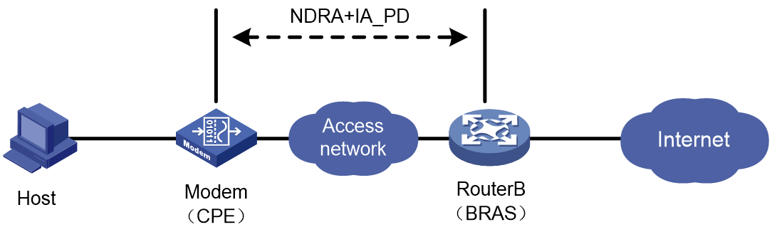
In the network as shown in Figure 13, if a CEP fails to come online through IA_PD, hosts attached to the CPE cannot generate global unicast IPv6 addresses to access network resources. In this case, even if the CPE comes online through NDRA, the hosts cannot obtain IPv6 addresses. Additionally, the NDRS user entries of the CPE occupy the system resources of the BRAS. As a best practice to resolve this issue, use this command to allow users to come online through ND RS only after they come online through IA_PD in an NDRA+DHCPv6 (IA_PD) network.
Restrictions and guidelines
For users to successfully come online through ND RS in any other network, do not configure this feature.
Procedure
1. Enter system view.
system-view
2. Enter interface view.
interface interface-type interface-number
3. Allow users to come online through ND RS only after they come online through IA_PD on the interface.
ip subscriber ndrs wait-delegation-prefix
By default, the users can come online through IA_PD and ND RS in any order.
Configuring static users
Static user tasks at a glance
To configure static individual users, perform the following tasks:
1. Configuring a static session initiation method
2. Configuring static individual sessions
3. Configuring static leased sessions
4. (Optional.) Configuring authentication user naming conventions for static users
5. (Optional.) Configuring passwords for static users
6. (Optional.) Configuring ISP domains for static users
7. (Optional.) Configuring session conflict detection
Configuring a static session initiation method
About this task
For IP packets to initiate static sessions, you must enable unclassified-IP packet initiation.
For ARP packets to initiate IPv4 static sessions, you must enable ARP packet initiation. Disabling ARP packet initiation does not affect online ARP-initiated static users.
For NS or NA packets to initiate IPv6 static sessions, you must enable NS/NA packet initiation. Disabling NS/NA packet initiation does not affect online NS/NA-initiated static users.
Restrictions and guidelines
The gateway IP address allocated to the static users must be one of the following IP addresses:
· The IP address of the access interface.
· A shared gateway address in the IP address pool (for example, a gateway address specified by using the gateway command in a BAS IP address pool).
NS or NA packets can initiate sessions only in Layer 2 access mode. For a user to initiate a session by using NS/NA packets, execute the ip subscriber initiator nsna enable command to enable NS/NA packet initiation.
If you specify a global static user with an IPv6 delegation prefix, users matching the session can come online only when the interface is configured to operate in Layer 2 access mode and uses the bind authentication mode.
Procedure
1. Enter system view.
system-view
2. Enter interface view.
interface interface-type interface-number
3. Configure an IPv4 static session initiation method. Choose the options to configure as needed:
¡ Enable unclassified-IPv4 packet initiation.
ip subscriber initiator unclassified-ip enable [ matching-user ]
By default, unclassified-IPv4 packet initiation is not enabled.
¡ Enable ARP packet initiation.
ip subscriber initiator arp enable
By default, ARP packet initiation is disabled.
4. Configure an IPv6 static session initiation method. Choose the options to configure as needed:
¡ Enable unclassified-IPv6 packet initiation.
ip subscriber initiator unclassified-ipv6 enable [ matching-user ]
By default, unclassified-IPv6 packet initiation is disabled.
¡ Enable NS/NA packet initiation.
ip subscriber initiator nsna enable
By default, NS/NA packet initiation is disabled.
Configuring static individual sessions
About this task
Static individual users initiate IPoE sessions by sending IP, ARP, NS, or NA packets. If an IP or ARP packet matches a manually configured IPoE session, the BRAS authenticates the user and establishes an IPoE session.
Interface-level static individual sessions take precedence over global static individual sessions.
Restrictions and guidelines
On one interface, a maximum of one static individual session can be configured for one IP address.
A maximum of one global static individual session can be configured for one IP address in the public network or a VPN instance.
Configuration prerequisites
As a best practice to avoid conflict of IP addresses used by dynamic and static users, perform the following tasks:
· Before configuring an IPv4 static individual session or dual-stack individual session, make sure the following conditions are met:
¡ DHCP has been enabled by using the dhcp enable command.
¡ All IPv4 addresses specified in the static session are excluded from dynamic allocation by using the forbidden-ip command in the IP address pool. For more information about IP address pools and the forbidden-ip and dhcp enable commands, see DHCP configuration in BRAS Services Configuration Guide.
· Before configuring IPv6 static individual sessions or dual-stack static individual sessions, make sure all IPv6 addresses to be specified in static sessions have already been excluded by using the forbidden-address command from the IPv6 address pool. For more information about the IPv6 address pool and the forbidden-address command, see DHCPv6 configuration in BRAS Services Configuration Guide.
Configuring interface-level static individual sessions
1. Enter system view.
system-view
2. (Optional). Configure the interval at which the device sends online requests to static individual users.
ip subscriber static-session request-online interval seconds
By default, the interval at which the device sends online requests to static individual users is 180 seconds.
3. Enter interface view.
interface interface-type interface-number
4. Configure IPv4 static individual sessions.
ip subscriber session static ip start-ipv4-address [ end-ipv4-address ] [ vlan vlan-id [ second-vlan vlan-id ] ] [ mac mac-address ] [ domain domain-name ] [ password mac ] [ request-online ] [ description string ] [ gateway ip ipv4-address ] [ vpn-instance vpn-instance-name ] [ keep-online ]
By default, no IPv4 static individual session is configured.
5. Configure IPv6 static individual sessions.
ip subscriber session static ipv6 start-ipv6-address[ end-ipv6-address ] [ vlan vlan-id [ second-vlan vlan-id ] ] [ mac mac-address ] [ domain domain-name ] [ password mac ] [ request-online ] [ description string ] [ gateway ipv6 ipv6-address ] [ vpn-instance vpn-instance-name ] [ keep-online ]
By default, no IPv6 static individual session is configured.
6. Configure dual-stack static individual sessions.
ip subscriber session static ip start-ipv4-address [ end-ipv4-address ] ipv6 start-ipv6-address [ end-ipv6-address ] [ vlan vlan-id [ second-vlan vlan-id ] ] [ mac mac-address ] [ domain domain-name ] [ password mac ] [ request-online { ip | ipv6 } ] [ description string ] [ gateway { ip ipv4-address | ipv6 ipv6-address } * ] [ vpn-instance vpn-instance-name ] [ keep-online ]
By default, no dual-stack static individual session is configured.
If you first enable IPoE and then configure dual-stack static users, you must enable IPoE for both IPv4 and IPv6 protocol stacks in order that you can configure dual-stack static users. If you first configure dual-stack static users and then enable IPoE, you must enable IPoE for both IPv4 and IPv6 stacks. Otherwise, you cannot enable IPoE.
Configuring global static individual sessions
1. Enter system view.
system-view
2. Create a static user interface list and enter its view.
static-user interface-list list-id
You need to perform this step only when you use syntax II to configure global static individual users.
3. Add an interface to the static user interface list.
add interface interface-type interface-number
By default, an interface is not added to a static user interface list.
You need to perform this step only when you use syntax II to configure global static individual users.
4. Configure global IPv4 static individual sessions.
Syntax I:
ip subscriber session static ip start-ipv4-address [ end-ipv4-address ] [ mac mac-address ] [ domain domain-name ] [ password mac ] [ interface interface-type interface-number [ vlan vlan-id [ second-vlan vlan-id ] ] [ request-online ] ] [ description string ] [ gateway ip ipv4-address ] [ vpn-instance vpn-instance-name ] [ keep-online | support-ds ]
Syntax II:
ip subscriber session static ip start-ipv4-address [ end-ipv4-address ] interface-list list-id [ mac mac-address ] [ domain domain-name ] [ password mac ] [ description string ] [ vpn-instance vpn-instance-name ] [ keep-online | support-ds ]
By default, no global IPv4 static individual session is configured.
5. Configure global IPv6 static individual sessions.
Syntax I:
ip subscriber session static ipv6 start-ipv6-address [ end-ipv6-address ] [ delegation-prefix start-ipv6-prefix [ end-ipv6-prefix ] prefix-length ] [ mac mac-address ] [ domain domain-name ] [ password mac ] [ interface interface-type interface-number [ vlan vlan-id [ second-vlan vlan-id ] ] [ request-online ] ] [ description string ] [ gateway ipv6 ipv6-address ] [ vpn-instance vpn-instance-name ] [ keep-online | support-ds ]
Syntax II:
ip subscriber session static ipv6 start-ipv6-address [ end-ipv6-address ] interface-list list-id [ delegation-prefix start-ipv6-prefix [ end-ipv6-prefix ] prefix-length ] [ mac mac-address ] [ domain domain-name ] [ password mac ] [ description string ] [ vpn-instance vpn-instance-name ] [ keep-online | support-ds ]
By default, no global IPv6 static individual session is configured.
6. Configure global dual-stack static individual sessions.
Syntax I:
ip subscriber session static ip start-ipv4-address [ end-ipv4-address ] ipv6 start-ipv6-address [ end-ipv6-address ] [ delegation-prefix start-ipv6-prefix [ end-ipv6-prefix ] prefix-length ] [ mac mac-address ] [ domain domain-name ] [ password mac ] [ interface interface-type interface-number [ vlan vlan-id [ second-vlan vlan-id ] ] [ request-online [ ip | ipv6 ] ] [ description string ] [ gateway { ip ipv4-address | ipv6 ipv6-address } * ] [ vpn-instance vpn-instance-name ] [ keep-online ]
Syntax II:
ip subscriber session static ip start-ipv4-address [ end-ipv4-address ] ipv6 start-ipv6-address [ end-ipv6-address ] interface-list list-id [ delegation-prefix start-ipv6-prefix [ end-ipv6-prefix ] prefix-length ] [ mac mac-address ] [ domain domain-name ] [ password mac ] [ description string ] [ vpn-instance vpn-instance-name ] [ keep-online ]
By default, no global dual-stack static individual session is configured.
When you configure dual-stack static sessions with the interface keyword specified, follow these restrictions and guidelines:
¡ If you first enable IPoE on the interface specified by the interface keyword and then configure dual-stack static users, you must enable IPoE for both IPv4 and IPv6 protocol stacks in order that you can configure dual-stack static users.
¡ If you first configure dual-stack static users and then enable IPoE on the interface specified by the interface keyword, you must enable IPoE for both IPv4 and IPv6 stacks. Otherwise, you cannot enable IPoE.
7. (Optional). Configure the interval at which the device sends online requests to static individual users.
ip subscriber static-session request-online interval seconds
By default, the interval at which the device sends online requests to static individual users is 180 seconds.
Configuring static leased sessions
About this task
As shown in Figure 14, in a service provider leased line, the Layer 3 device Device of an enterprise has multiple hosts attached. The uplink port Port A of Device needs a public network IP address assigned by the service provider. The BRAS device needs to perform unified authentication, authorization, and accounting for all hosts attached to Device. In this case, for the administrator to properly allocate and easily maintain public network IP addresses in addition to meeting the leased line service requirements, the administrator also hopes to search for the public network IP addresses allocated to the device of each leased line service on the BRAS. To meet these requirements, you can deploy IPoE static leased lines on the BRAS.
Figure 14 IPoE static leased line application network diagram
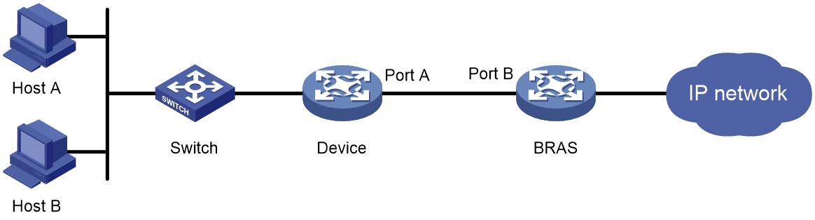
A static leased session is a special type of leased line in the following aspects:
· Independent service attributes—Similar to an interface-leased line, unified authentication, authorization, and accounting are performed for all users on an interface. When a static leased session comes online, packets with any source IP address can pass through the leased interface.
· Packet initiation—Similar to a global static individual session, with IPoE enabled on an access interface in up state, when IP, ARP, NS, or NA packets pass through the access device, the access interface will try to initiate authentication by using the configured username and password. If a user passes authentication, a static leased session is established. If a user fails to pass authentication, no static leased session is established.
Restrictions and guidelines
Only one static leased session can be configured on an interface.
Static leased sessions are supported only when the bind authentication mode is used and IPoE operates in Layer 2 access mode.
On the access interface of a static user, you cannot configure an IPv4 address or IPv6 global unicast address. Follow these restrictions and guidelines:
· For IPv4: Use the shared gateway address in the IP address pool, for example, the gateway address specified by using the gateway command in a BAS IP address pool.
· For IPv6: Use the ipv6 address auto link-local command to generate a link-local address on the access interface of the static user.
Prerequisites
As a best practice to avoid conflict of IP addresses used by dynamic and static users, perform the following tasks:
· Before configuring IPv4 IPoE static leased sessions or dual-stack IPoE static leased sessions, make sure DHCP has been enabled by using the dhcp enable command, and all IPv4 addresses to be specified in static leased sessions have already been excluded by using the forbidden-ip command from the IP address pool. For more information about the dhcp enable command, IP address pool, and the forbidden-ip command, see DHCP configuration in BRAS Services Configuration Guide.
· Before configuring IPv6 IPoE static leased sessions or dual-stack IPoE static leased sessions, make sure all IPv6 addresses to be specified in static leased sessions have already been excluded by using the forbidden-address command from the IPv6 address pool. For more information about the IPv6 address pool and the forbidden-address command, see DHCPv6 configuration in BRAS Services Configuration Guide.
Procedure
1. Enter system view.
system-view
2. Configure an IPv4 IPoE static leased session.
ip subscriber session static-leased ip ipv4-address interface interface-type interface-number [ vlan vlan-id [ second-vlan vlan-id ] ] [ mac mac-address ] [ domain domain-name ] [ password mac ] [ request-online ] [ description string ] [ gateway ip ipv4-address ] [ vpn-instance vpn-instance-name ] [ keep-online ]
By default, no IPv4 IPoE static leased session is configured.
3. Configure an IPv6 IPoE static leased session.
ip subscriber session static-leased ipv6 ipv6-address interface interface-type interface-number [ vlan vlan-id [ second-vlan vlan-id ] ] [ mac mac-address ] [ domain domain-name ] [ password mac ] [ request-online ] [ description string ] [ gateway ipv6 ipv6-address ] [ vpn-instance vpn-instance-name ] [ keep-online ]
By default, no IPv6 IPoE static leased session is configured.
4. Configure a dual-stack IPoE static leased session.
ip subscriber session static-leased ip ipv4-address ipv6 ipv6-address interface interface-type interface-number [ vlan vlan-id [ second-vlan vlan-id ] ] [ mac mac-address ] [ domain domain-name ] [ password mac ] [ request-online [ ip | ipv6 ] ] [ description string ] [ gateway { ip ipv4-address | ipv6 ipv6-address } * ] [ vpn-instance vpn-instance-name ] [ keep-online ]
By default, no dual-stack IPoE static leased session is configured.
Configuring authentication user naming conventions for static users
About this task
Usernames configured for static users must be the same as those configured on the AAA server.
For bind authentication, a username is selected in the following order for static users until a match is found:
1. Username obtained by using the ip subscriber unclassified-ip username command.
2. Username configured by using the ip subscriber username command.
3. Source IP address of packets.
For Web authentication and Web MAC authentication in the preauthentication phase, a username is selected in the following order for static users until a match is found:
1. Username obtained by using the ip subscriber unclassified-ip username command.
2. Username configured by using the ip subscriber username command.
3. Source IP address of packets.
For Web authentication in the Web authentication phase, a username is selected in the following order for static users until a match is found:
1. Username that the user enters when logging in.
2. Username configured by using the ip subscriber username command.
3. Source IP address of packets.
For Web MAC authentication in the Web authentication phase, a username is selected in the following order for static users until a match is found:
1. Username configured by using the ip subscriber username command.
2. Source IP address of packets.
Procedure
1. Enter system view.
system-view
2. Enter interface view.
interface interface-type interface-number
3. Configure an authentication user naming convention for static users.
ip subscriber unclassified-ip username include { nas-port-id [ separator separator ] | port [ separator separator ] | second-vlan [ separator separator ] | slot [ separator separator ] | source-ip [ address-separator address-separator ] [ separator separator ] | source-mac [ address-separator address-separator ] [ separator separator ] | string string [ separator separator ] | subslot [ separator separator ] | sysname [ separator separator ] | vlan [ separator separator ] } *
The default username is the source IP address of packets sent by users.
Configuring passwords for static users
About this task
Passwords configured for static users must be the same as those configured on the AAA server.
For bind authentication, a password is selected in the following order for static users until a match is found:
1. User MAC address when the password mac keywords are specified in the ip subscriber session static command.
2. Password configured by using the ip subscriber password command.
3. The string vlan.
For Web authentication and Web MAC authentication in the preauthentication phase, a password is selected in the following order for static users until a match is found:
1. User MAC address when the password mac keyword is specified in the ip subscriber session static command.
2. Password configured by using the ip subscriber password command.
3. The string vlan.
For Web authentication in the Web authentication phase, a password is selected in the following order for static users until a match is found:
1. Password that the user enters when logging in.
2. Password configured by using the ip subscriber password command.
3. The string vlan.
For Web MAC authentication in the Web authentication phase, a password is selected in the following order for static users until a match is found:
1. Password configured by using the ip subscriber password command.
2. The string vlan.
Procedure
1. Enter system view.
system-view
2. Enter interface view.
interface interface-type interface-number
3. Set the password for static users.
ip subscriber password { ciphertext | plaintext } string
The default password for a static user is vlan.
Configuring ISP domains for static users
About this task
If you configure multiple ISP domains for a static user, an ISP domain is selected for the user in the following order until a match is found:
· When bind authentication is used:
a. ISP domain specified by using the domain domain-name option in the ip subscriber session static command. If the ISP domain has not been created, the user fails to come online.
b. Service-specific domain. If the ISP domain has not been created, the user fails to come online.
c. ISP domain configured by using the ip subscriber unclassified-ip domain command. If the ISP domain has not been created, the user fails to come online.
d. ISP domain selected by the AAA module. For more information, see AAA configuration in BRAS Services Configuration Guide.
· When Web authentication is used, for how the BRAS selects ISP domains for static users, see "Configuring an ISP domain for Web authentication individual users."
For more information about configuring service-specific ISP domains, see "Configuring service-specific ISP domains." For more information about configuring the default system domain, see Security Configuration Guide.
Restrictions and guidelines
The specified ISP domain must exist on the BRAS.
Procedure
1. Enter system view.
system-view
2. Enter interface view.
interface interface-type interface-number
3. Configure an ISP domain for unclassified-IP users.
ip subscriber unclassified-ip domain domain-name
By default, no ISP domain is configured for unclassified-IP users.
Configuring session conflict detection
About this task
In a Layer 2 IPoE network, after an IPoE session moves from an interface to another interface, the device still maintains the session information on the original interface. This wastes resources and increases maintenance complexity.
When a user comes online on an interface, this feature uses the user's IP address and MAC address to detect whether the user has come online on other interfaces. If yes, this feature forcibly logs out the user from other interfaces.
Restrictions and guidelines
This feature takes effect only when IPoE operates in Layer 2 access mode.
This feature takes effect only on IPoE global static users whose sessions do not have the interface keyword specified.
This feature is mutually exclusive with roaming configuration on an interface.
Procedure
1. Enter system view.
system-view
2. Enter interface view.
interface interface-type interface-number
3. Configure session conflict detection.
ip subscriber session-conflict action offline
By default, session conflict detection is disabled.
Configuring leased users
Leased user tasks at a glance
To configure leased users, perform the following tasks:
1. Configuring leased users
¡ Configuring an interface-leased user
¡ Configuring subnet-leased users
¡ Configuring an L2VPN-leased user
Interface-leased users, subnet-leased users, and L2VPN-leased users cannot be configured on the same interface.
2. Configuring ISP domains for leased users
Configuring an interface-leased user
About this task
An interface-leased user represents all access users of the interface. AAA is performed for these users uniformly. With IPoE enabled for both IPv4 and IPv6 protocol stacks on an interface in up state, the session does not need to be initiated by user traffic. The BRAS actively initiates authentication by using the configured username and password. After the authentication succeeds and the leased session is successfully set up for users, traffic of all users on the interface is permitted, and the users share one IPoE session.
When leased users are in Layer 2 access mode, all IP users who access the BRAS through an IPoE interface are called subusers. Use the display access-user or cut access-user command to view or delete the subuser information. For more information about viewing and deleting subuser information, see UCM commands in BRAS Services Command Reference.
Restrictions and guidelines
You can configure up to one interface-leased user on an interface.
Interface-leased subusers support DHCP packet initiation, unclassified-IP packet initiation, and IPv6 ND RS packet initiation.
The interface-leased subusers initiated by IPv6 ND RS packets support only the prefix sharing scenario, and do not support the scenario of one prefix per user.
If you first enable IPoE and then configure interface-leased users, you must enable IPoE for both IPv4 and IPv6 protocol stacks in order that you can configure interface-leased users. If you first configure interface-leased users and then enable IPoE, you must enable IPoE for both IPv4 and IPv6 stacks. Otherwise, you cannot enable IPoE.
Procedure
1. Enter system view.
system-view
2. Enter interface view.
interface interface-type interface-number
3. Configure an interface-leased user.
ip subscriber interface-leased username name password { ciphertext | plaintext } string [ domain domain-name ]
By default, no interface-leased user is configured.
Configuring subnet-leased users
About this task
A subnet-leased user on an interface refers to all IP users in the specified subnet on the interface. AAA is performed for these users uniformly.
When subnet-leased users are in Layer 2 access mode, all IP users who access the BRAS through an IPoE interface are called subusers. Use the display access-user or cut access-user command to view or delete the subuser information. For more information about viewing and deleting subuser information, see UCM commands in BRAS Services Command Reference.
Restrictions and guidelines
You can configure multiple subnet-leased users on an interface. Make sure these subnets do not overlap. Each subnet can be bound to only one subnet-leased user.
In the current software version, subnet-leased subusers support only unclassified-IP packet initiation.
If you first enable IPoE and then configure subnet-leased users, you must enable IPoE for the IPv4 or IPv6 protocol stack in order that you can configure subnet-leased users for the protocol stack. If you first configure subnet-leased users and then enable IPoE, you must enable IPoE for the protocol stack of the subnet-leased users or dual stacks.
For IPv4 subnet-leased users, you must execute the dhcp enable command to enable DHCP. For more information this command, see DHCP commands in BRAS Services Command Reference.
For IPv6 subnet-leased users, you must execute DHCPv6 operation commands (for example, the ipv6 pool command) to enable DHCPv6. For more information this command, see DHCPv6 commands in BRAS Services Command Reference.
Procedure
1. Enter system view.
system-view
2. Enter interface view.
interface interface-type interface-number
3. Configure an IPv4 subnet-leased user.
ip subscriber subnet-leased ip ipv4-address { mask | mask-length } username name password { ciphertext | plaintext } string [ domain domain-name ] [ vpn-instance vpn-instance-name ]
By default, no IPv4 subnet-leased user is configured.
4. Configure an IPv6 subnet-leased user.
ip subscriber subnet-leased ipv6 ipv6-address prefix-length username name password { ciphertext | plaintext } string [ domain domain-name ] [ vpn-instance vpn-instance-name ]
By default, no IPv6 subnet-leased user is configured.
Configuring an L2VPN-leased user
About this task
An L2VPN-leased user represents hosts that rent the same interface on an L2VPN network.
Restrictions and guidelines
You can configure one L2VPN-leased user on an interface on an L2VPN network. An L2VPN-leased user carries IPv4 and IPv6 traffic from hosts. On a Layer 3 Ethernet or aggregate subinterface, the L2VPN-leased user is mutually exclusive with the packet statistics collection feature. For more information about packet statistics collection on Ethernet subinterfaces, see Ethernet interface configuration in Interface Configuration Guide. For more information about packet statistics collection on Layer 3 aggregate subinterfaces, see Ethernet link aggregation configuration in Layer 2—LAN Switching Configuration Guide.
If you first enable IPoE and then configure L2VPN-leased users, you must enable IPoE for both IPv4 and IPv6 protocol stacks in order that you can configure L2VPN-leased users. If you first configure L2VPN-leased users and then enable IPoE, you must enable IPoE for both IPv4 and IPv6 stacks. Otherwise, you cannot enable IPoE.
Procedure
1. Enter system view.
system-view
2. Enter interface view.
interface interface-type interface-number
3. Configure an L2VPN-leased user.
ip subscriber l2vpn-leased username name password { ciphertext | plaintext } string [ domain domain-name ]
By default, no L2VPN-leased user is configured.
Configuring ISP domains for leased users
About this task
An ISP domain is selected for an IPoE leased user in the following order until a match is found:
1. Service-specific ISP domain. If the ISP domain has not been created, the user fails to come online.
2. ISP domain specified for the leased user by using the specific command:
¡ For an interface-leased user, ISP domain specified by using the domain domain-name option in the ip subscriber interface-leased command. If the ISP domain has not been created, the user fails to come online.
¡ For a subnet-leased user, ISP domain specified by using the domain domain-name option in the ip subscriber subnet-leased command. If the ISP domain has not been created, the user fails to come online.
¡ For an L2VPN-leased user, ISP domain specified by using the domain domain-name option in the ip subscriber l2vpn-leased command. If the ISP domain has not been created, the user fails to come online.
3. ISP domain specified by using the ip subscriber unclassified-ip domain command. (Applicable to only interface-leased users and subnet-leased users.) If the ISP domain has not been created, the user fails to come online.
4. ISP domain selected by the AAA module. For more information, see AAA configuration in BRAS Services Configuration Guide.
For more information about configuring service-specific ISP domains, see "Configuring service-specific ISP domains."
Restrictions and guidelines
The specified ISP domain must exist on the BRAS.
Procedure
1. Enter system view.
system-view
2. Enter interface view.
interface interface-type interface-number
3. Configure a domain collectively for leased users.
ip subscriber unclassified-ip domain domain-name
By default, no ISP domain is configured for unclassified-IP users.
Configuring Web authentication advanced features
Web authentication advanced feature tasks at a glance
To configure Web authentication individual users, perform the following tasks:
1. (Optional.) Configuring an ISP domain for Web authentication individual users
2. (Optional.) Configuring HTTP packet fast reply
3. (Optional.) Configuring an SSL server policy for HTTPS redirection
4. (Optional.) Configuring URL redirection
5. (Optional.) Configuring the captive-bypass feature
6. (Optional.) Configuring Web authentication fail-permit
7. (Optional.) Configure the URL allowlist for Web authentication
8. (Optional.) Configuring authentication user naming conventions for dynamic individual users
9. (Optional.) Configuring passwords for dynamic individual users
10. (Optional.) Setting the dynamic individual session limit
11. (Optional.) Configuring trusted DHCP options for DHCP users
12. (Optional.) Allowing abnormally logged out IPoE users to come online again through packet initiation
13. (Optional.) Allowing DHCP users to access in loose mode
14. (Optional.) Configuring IPoE web support for HTTP/HTTPS attack defense
Configuring an ISP domain for Web authentication individual users
About this task
IPoE Web authentication process includes preauthentication and Web authentication phases. Web authentication is triggered when users pass preauthentication. The preauthenticated users obtain IP addresses (applicable to only DHCP users) and authorization attributes configured for the preauthentication domain. Web authentication is triggered when preauthenticated users access an unauthorized HTTP/HTTPS address.
The BRAS selects an ISP domain for Web authentication in the following order until a match is found:
· For static users:
a. Authentication domain configured by using the ip subscriber session static command. If the ISP domain has not been created, the user fails to come online.
b. Preauthentication domain configured by using the ip subscriber pre-auth domain command. If the ISP domain has not been created, the user fails to come online.
c. Service-specific domain. If the ISP domain has not been created, the user fails to come online.
d. Domain configured by using the ip subscriber unclassified-ip domain command. If the ISP domain has not been created, the user fails to come online.
e. ISP domain selected by the AAA module. For more information, see AAA configuration in BRAS Services Configuration Guide.
· For dynamic DHCP users:
a. Domain information obtained from the option. For how domain information is obtained from the option, see how domain information is obtained from the option in the bind authentication method. If the ISP domain has not been created, proceed with the next step.
b. Service-specific domain. If the ISP domain has not been created, the user fails to come online.
c. Preauthentication domain configured by using the ip subscriber pre-auth domain command. If the ISP domain has not been created, the user fails to come online.
d. ISP domain selected by the AAA module. For more information, see AAA configuration in BRAS Services Configuration Guide.
· For dynamic IPv6 ND RS users:
a. Preauthentication domain configured by using the ip subscriber pre-auth domain command. If the ISP domain has not been created, the user fails to come online.
b. ISP domain selected by the AAA module. For more information, see AAA configuration in BRAS Services Configuration Guide.
When Web authentication is used, if multiple types of ISP domains are configured, an ISP domain is selected in the following order during the Web authentication phase:
1. Domain carried in the username is used. If the domain has not been created, the user fails to come online.
2. Web authentication domain specified by using the ip subscriber web-auth domain command. If the specified domain has not been created, the user fails to come online.
3. ISP domain selected by the AAA module. For more information, see AAA configuration in BRAS Services Configuration Guide.
When Web MAC authentication is used, if multiple types of ISP domains are configured, an ISP domain is selected in the following order during the Web authentication phase:
1. Domain carried in the username. If the domain has not been created, the user fails to come online.
2. MAC authentication domain specified by using the ip subscriber mac-auth domain command. If the specified domain has not been created, the user fails to come online. (Applicable to only transparent MAC authentication.)
3. Web authentication domain specified by using the ip subscriber web-auth domain command. If the specified domain has not been created, the user fails to come online
4. ISP domain selected by the AAA module. For more information, see AAA configuration in BRAS Services Configuration Guide.
Procedure
1. Enter system view.
system-view
2. Enter interface view.
interface interface-type interface-number
3. Configure a preauthentication ISP domain.
ip subscriber pre-auth domain domain-name
By default, no preauthentication ISP domain is configured.
4. Configure the domain for MAC authentication.
ip subscriber mac-auth domain domain-name
By default, no domain is configured for MAC authentication.
The domain for MAC authentication is used for transparent MAC authentication during the Web authentication phase for only individual users using Web MAC authentication.
5. Configure the domain for Web authentication.
ip subscriber web-auth domain domain-name
By default, no domain is configured for Web authentication.
The ISP domain configured for Web authentication applies to only individual users using Web authentication and Web MAC authentication during the Web authentication phase.
Configuring HTTP packet fast reply
About this task
When a user using a browser to perform Web authentication does not access the portal Web server, the access device will redirect the HTTP requests to the CPU. Then, the CPU pushes the Web authentication page of the portal Web server to the user. If an attacker sends a large number of HTTP requests to the device, the device suffers DoS attacks.
With this feature enabled on an interface, the device uses hardware to recognize HTTP requests and automatically responds with HTTP replies. This feature reduces the workload of the CPU and prevents DoS attacks.
Restrictions and guidelines
In standard system operating mode, only the following cards support this feature and the maximum URL length in fast HTTP replies is 178 bytes: CSPEX-1304X, CSPEX-1404X, CSPEX-1502X, CSPEX-1504X, CSPEX-1504XA, CSPEX-1602X, CSPEX-1602XA, CSPEX-1804X, CSPEX-1512X, CSPEX-1612X, CSPEX-1812X, RX-SPE200, CEPC-XP4LX, CEPC-XP24LX, CEPC-XP48RX, CEPC-CP4RX, CEPC-CP4RXA, CEPC-CP4RX-L, CSPEX-1802X, CSPEX-1802XA, CSPEX-1812X-E, CSPEX-2304X-G, RX-SPE200-E, CSPEX-1502XA.
In SDN-WAN system operating mode, only the following cards support this feature and the maximum URL length in fast HTTP replies is 178 bytes: CSPEX-1802X, CSPEX-1802XA, CSPEX-1812X-E, CSPEX-2304X-G, RX-SPE200-E, CSPEX-1502XA.
This feature does not immediately take effect on users that have passed preauthentication and come online before this feature is enabled. This feature takes effect only when these users go offline and come online again after passing preauthentication or return to the preauthentication domain after passing Web authentication.
With both this feature and transparent authentication configured, a user first attempts to come online through transparent authentication. The hardware responds and pushes the Web authentication page if the user fails to come online through transparent authentication for one of the following reasons:
· Transparent authentication binding query request times out.
· The portal server returns a message showing that the user is not bound.
· The AAA server returns authentication failure.
Procedure
1. Enter system view.
system-view
2. Enter interface view.
interface interface-type interface-number
3. Enable HTTP packet fast reply.
ip subscriber http-fast-reply enable
By default, HTTP packet fast reply is disabled.
Configuring an SSL server policy for HTTPS redirection
About this task
When a DHCP user uses HTTPS packets to trigger Web authentication, you can use the default SSL server policy or customize an SSL server policy.
Procedure
1. Configure a PKI policy, and successfully apply for or import local certificates and CA certificates. For more information, see PKI configuration in Security Configuration Guide.
2. Configure an SSL server policy named https_redirect, and specify the policy to use an existing PKI domain.
You must install a certificate that the browser trusts. Otherwise, the browser displays the alarm that "The used certificate is insecure" when you set up an SSL connection to the device on the browser. For more information, see SSL configuration in Security Configuration Guide.
Configuring URL redirection
About this task
This feature pushes authentication pages to users based on the user-requested URL or User-Agent information.
A URL redirection match rule matches HTTP or HTTPS requests by user-requested URL or User-Agent information, and redirects the matching HTTP or HTTPS requests to the specified redirection URL.
For a user to successfully access a redirection URL, configure a preauthentication domain user group ACL to allow HTTP or HTTPS requests destined for the redirection URL to pass.
You can configure the web-server { url | ipv6-url } command in an ISP domain and the ip subscriber if-match command for URL redirection. The web-server { url | ipv6-url } command redirects all HTTP or HTTPS requests from unauthenticated users to the Web server for authentication. The ip subscriber if-match command allows for flexible URL redirection by redirecting specific HTTP or HTTPS requests to specific redirection URLs. If both commands are executed, the ip subscriber if-match command takes priority to perform URL redirection.
Restrictions and guidelines
In a CUPS network, this feature takes effect only when it is configured on a UP.
Procedure
1. Configure an ACL to permit HTTP or HTTPS packets destined for the redirection URL.
For more information about configuring ACLs, see ACL and QoS Configuration Guide.
2. Enter system view.
system-view
3. Enter interface view.
interface interface-type interface-number
4. Configure a URL redirection match rule.
ip subscriber if-match { original-url url-string redirect-url url-string [ url-param-encryption { aes | des } key { cipher | simple } string ] | user-agent user-agent redirect-url url-string }
By default, no URL redirection rule is configured.
Configuring the captive-bypass feature
About this task
By default, the device automatically pushes the Web authentication page to the iOS devices and some Android devices when they are connected to the network with IPoE Web authentication enabled. With the captive-bypass feature enabled, the device does not automatically push the Web authentication page to iOS devices and some Android devices when they are connected to the network. The device pushes the Web authentication page only when the user accesses the Internet by using a browser.
Procedure
1. Enter system view.
system-view
2. Enter interface view.
interface interface-type interface-number
3. Enable the captive-bypass feature.
ip subscriber captive-bypass enable [ android | ios ] [ optimize ]
By default, the captive-bypass feature is disabled.
If you execute this command multiple times, the most recent configuration takes effect.
Configuring Web authentication fail-permit
About this task
With this feature configured, when the device detects that the Web authentication server or AAA server is unreachable, the device allows users to access network resources without Web authentication. You can implement Web authentication fail-permit by associating a fail-permit user group with a track entry.
By default, the Web authentication users that come online in the preauthentication domain belong to the user group authorized by AAA or authorized in the ISP domain when the users come online. After a fail-permit user group is associated with a track entry, the following rules apply:
· When the status of the track entry becomes Negative, the access device moves all online users in the current preauthentication domain from the authorized user group to the fail-permit user group. Then, the users can access network resources according to the privilege of the fail-permit user group.
· When the status of the track entry becomes Positive, the access device will move all online users in the current preauthentication domain back to the authorized user group. Then, the users can access network resources only after passing Web authentication.
Restrictions and guidelines
This command takes effect only on users in the preauthentication domain.
Procedure
1. Configure a track entry.
Track can monitor the server status in various method, such as NQA and BFD. For more information, see track configuration in High Availability Configuration Guide.
2. Configure the privilege for a fail-permit user group.
For information on how to configure a user group, see AAA configuration in BRAS Services Configuration Guide.
3. Enter system view.
system-view
4. Enter interface view.
interface interface-type interface-number
5. Associate the fail-permit user group with the track entry.
ip subscriber pre-auth track track-entry-number fail-permit user-group group-name
By default, the fail-permit user group is not associated with a track entry.
If you execute this command multiple times, the most recent configuration takes effect.
Configure the URL allowlist for Web authentication
About this task
With this feature configured, the unauthenticated or defaulting users can still access the network resource list.
For example, on a campus network that uses IPoE Web authentication, you can add the internal websites of the campus and the payment page to the URL allowlist.
· When a student does not pass IPoE Web authentication or has passed IPoE Web authentication but has owed fees, the student is still allowed to access the internal websites of the campus. In this way, the student can still learn and communicate normally.
· When a student owes fees, the student can still access the payment page of the service provider and pay the charge on the payment page pushed by the service provider. In this way, the student can quickly restore access to Internet.
Depending on the application scenarios, the URL allowlists for IPoE Web authentication include IP-based URL allowlists and domain name-based URL allowlists.
Restrictions and guidelines
The URL allowlists for IPoE Web authentication are implemented through object groups. For more information about object groups, see object group configuration in Security Configuration Guide.
Procedure
1. Configure an object group.
This configuration is used to define the URL allowlist, including the internal websites of the campus and the payment page.
a. Enter system view.
system-view
b. Create an object group.
IPv4:
object-group ip address object-group-name
By default, the system default IPv4 address object group named any exists.
IPv6:
Create an IPv6 address object group, and enter its view.
object-group ipv6 address object-group-name
By default, the system default IPv6 address object group named any exists.
c. Configure the URL allowlist. Choose at least one of the following items.
- Configure an IP address-based URL allowlist.
network host address ip-address
For more information about this command, see object group commands in Security Command Reference.
- Configure a domain name-based URL allowlist.
network host name host-name
For more information about this command, see object group commands in Security Command Reference.
2. Configure user groups.
This configuration is used to authorize users in different application scenarios. (Details not shown.)
3. Configure and apply a QoS policy.
a. Configure an ACL.
This ACL is used to match packets that users in the specified user group use to access the addresses on the allowlist.
b. Define a class to match the service flows of users. Use the ACL configured in the step above as the match criterion in the class. Configure a traffic behavior, and specify the actions to take on users before passing authentication and defaulting users.
c. Create a QoS policy, and associate the traffic class with the traffic behavior.
d. Apply the QoS policy to the inbound and outbound directions of user traffic.
(Details not shown.) For more information about ACL and QoS commands, see QoS policy configuration in ACL and QoS Configuration Guide.
Configuring IPoE web support for HTTP/HTTPS attack defense
About this task
When various tool software products (for example, Baidu cloud) are installed on a client, each tool software product will periodically send HTTP/HTTPS requests to a fixed destination IP address. HTTP/HTTPS requests generated by these tool software products will result in high resource usage before users perform IPoE Web authentication. As a result, the authentication efficiency of users is affected, and the authentication might even fail. To resolve this issue, you can enable destination IP-based IPoE HTTP/HTTPS attack defense. Use the attack defense function in the following scenarios:
· To limit the HTTP/HTTPS requests frequently initiated and reduce the resource usage of these massive HTTP/HTTPS packets, use the ip subscriber http-defense destination-ip enable action block command to generate blocking entries when the blocking conditions are met and block HTTP/HTTPS requests sent to the specified destination IP addresses based on the blocking entries.
· Blocking HTTP/HTTPS requests will affect users’ access to the specified destination IP addresses. To only detect the HTTP/HTTPS requests frequently initiated to the specified destination IP addresses rather than block them, use the ip subscriber http-defense destination-ip enable action logging command to output attack logs and generate attack defense blocking entries that are used to view blocked users. These attack defense blocking entries will not block attack packets. The generated attack log messages by the device will be sent to the information center. The information center configuration specifies the log message sending rule and destination. For more information about the information center, see Network Management and Monitoring Configuration Guide.
After you enable destination IP-based IPoE HTTP/HTTPS attack defense, the device will monitor and collect statistics of HTTP/HTTPS packets that IPoE Web preauthentication users send to any destination IP address. If the total number of HTTP/HTTPS packets sent to a destination IP address within a statistics collection interval exceeds the specified threshold, the device will generate blocking entries to block attack packets or output attack logs as configured in the ip subscriber http-defense destination-ip enable command.
During the packet blocking period, the device directly drops packets destined to the specified destination IP address to reduce the impact on the user onboarding speed. If the device receives packets sent to the destination IP address again after the blocking period expires, the device monitors and collects statistics of packets again.
Restrictions and guidelines
In standard system operating mode, only the following cards support this feature: CSPEX-1304X, CSPEX-1404X, CSPEX-1502X, CSPEX-1504X, CSPEX-1504XA, CSPEX-1602X, CSPEX-1602XA, CSPEX-1804X, CSPEX-1512X, CSPEX-1612X, CSPEX-1812X, RX-SPE200, CEPC-XP4LX, CEPC-XP24LX, CEPC-XP48RX, CEPC-CP4RX, CEPC-CP4RXA, CEPC-CP4RX-L, CSPEX-1802X, CSPEX-1802XA, CSPEX-1812X-E, CSPEX-2304X-G, RX-SPE200-E, CSPEX-1502XA.
In SDN-WAN system operating mode, only the following cards support this feature: CSPEX-1802X, CSPEX-1802XA, CSPEX-1812X-E, CSPEX-2304X-G, RX-SPE200-E, CSPEX-1502XA.
In the current software version, the IPoE HTTP/HTTPS attack defense function takes effect only on HTTP/HTTPS packets sent by IPoE Web users that have come online in the preauthentication domain.
If the administrator does not want to collect attack defense statistics of HTTP/HTTPS packets sent by users to the specified destination IP addresses and wants to unconditionally push the Web authentication page to users accessing these destination IP addresses, you can use the ip subscriber http-defense free-destination-ip command to add these destination IP addresses to the allowlist.
Procedure
1. Enter system view.
system-view
2. Enable destination IP-based IPoE HTTP/HTTPS attack defense.
ip subscriber http-defense destination-ip enable [ action { block [ period blocking-period ] | logging } ]
By default, destination IP-based IPoE HTTP/HTTPS attack defense is disabled.
3. (Optional.) Configure the threshold for IPoE HTTP/HTTPS attack defense.
ip subscriber http-defense destination-ip threshold packet-number interval interval
By default, when the total number of HTTP/HTTPS packets sent to the same destination IP address within 300 seconds reaches 6000, the attack defense threshold is triggered.
4. (Optional.) Configure allowlist addresses for IPoE HTTP/HTTPS attack defense.
ip subscriber http-defense free-destination-ip { ipv4-address | ipv6 ipv6-address } [ vpn-instance vpn-instance-name ]
By default, no allowlist addresses are configured for IPoE HTTP/HTTPS attack defense.
Execute this command multiple times to add multiple destination IP addresses to the allowlist.
Configuring IPoE quick Web authentication
Restrictions and guidelines
IPoE quick Web authentication is supported only in common mode.
When H3C IMC runs on the portal authentication server, the IP address specified on the server must be the same as the BAS-IP attribute carried in the portal packets. You can configure the BAS-IP attribute carried in the portal packets by using the portal bas-ip command.
Configuring transparent MAC-trigger authentication
Configuring the MAC binding server
For more information about the MAC binding server authentication, see "Configuring portal."
Specifying the MAC binding server on an interface
1. Enter system view.
system-view
2. Enter interface view.
interface interface-type interface-number
3. Specify a MAC binding server on the access interface of IPoE Web authentication users.
portal apply mac-trigger-server server-name
By default, no MAC binding server is specified on the access interface of IPoE Web authentication users.
For more information about this command, see portal commands in BRAS Services Command Reference.
Configuring transparent MAC authentication
Restrictions and guidelines
The AAA server used for transparent MAC authentication must support MAC binding.
Procedure
· Configure common transparent MAC authentication.
Configure IPoE to user Web MAC authentication.
· Configure re-DHCP transparent MAC authentication.
You can configure IPoE to use Web authentication or Web MAC authentication. As a best practice, configure IPoE to use Web authentication.
For more information, see "Configuring the authentication method."
Configuring the advanced 802.1X authentication features
Configuring the static 802.1X user authentication feature
About this task
Application scenarios
By default, in the IPoE 802.1X authentication scenario, IPoE 802.1X authentication supports DHCP users, IPv6 ND RS users, and static users. For a user configured with a static IP address to come online through 802.1X authentication, you must configure the corresponding static IPoE user access for the static IP address of the user on the BRAS.
For a user configured with a static IP address to come online through 802.1X authentication without configuring the corresponding static IPoE user access for the user on the BRAS, enable this feature.
Working mechanism
With this feature enabled, when the 802.1X client of a user passes authentication and comes online, the BRAS will generate a temporary session entry according to the MAC+VLAN information (without IP information) of the user. When the BRAS receives the ARP packets, unclassified-IP packets, and NS/NA packets of the user, the following rules apply:
· If a temporary session entry can be obtained for the user, IPoE uses the 802.1X authentication result to make the user directly come online in the postauthentication domain. After the user comes online in the postauthentication domain, the BRAS will replace the temporary session entry with the formal session entry of the user. Then, the BRAS processes packets of the user based on the formal session entry. In this case, the formal session entry records the 802.1X user information (including 802.1X username, authentication domain, and authorized attributes) of the user.
· If a temporary session entry cannot be obtained for the user, the packets are dropped.
Restrictions and guidelines
To deploy both dynamic 802.1X users and static 802.1X users on a live network, as a best practice, deploy them on different interfaces. For example, deploy them on different subinterfaces of the same main interface.
Both 802.1X authentication and IPoE static user access are configured on an interface, and the following functions are enabled:
· For 802.1X authentication access, the static 802.1X user authentication feature is enabled.
· For IPoE static user access, unclassified-IP packet initiation is enabled with the matching-user keyword specified.
If the preceding conditions are met, when the packets of a user received by the BRAS match both the 802.1X temporary session entry and the IPoE static user session, the user comes online as an IPoE static user.
With this feature enabled in the IPoE 802.1X authentication scenario, when the 802.1X client of a user passes authentication and comes online, only if the ARP packets, unclassified-IP packets, or NS/NA packets from the user can match the temporary session entry, the user can directly come online in the postauthentication domain, and you do not need to execute one of the following commands to enable ARP packet initiation, unclassified-IP packet initiation, or NS/NA packet initiation.
· ip subscriber initiator unclassified-ip enable
· ip subscriber initiator unclassified-ipv6 enable
· ip subscriber initiator arp enable
· ip subscriber initiator nsna enable
When you configure the static 802.1X user authentication feature, follow these restrictions and guidelines:
· On an interface, static 802.1X user authentication is mutually exclusive with Layer 3 IPoE access mode, IPoE interface-leased users, IPoE subnet-leased users, and IPoE L2VPN-leased users.
· You can configure static 802.1X user authentication on an interface only when the interface operates in Layer 2 IPoE access mode.
Procedure
1. Enter system view.
system-view
2. Enter interface view.
interface interface-type interface-number
3. Enable static 802.1X user authentication.
ip subscriber static-dot1x-user enable
By default, static 802.1X user authentication is disabled.
Forcibly logging out an 802.1X client
About this task
For an IPoE user that comes online through 802.1X authentication, the 802.1X client of the user refers to the 802.1X authentication-capable client software installed on the user's host.
By default, when the IP address lease expires or fails to be renewed for an IPoE DHCP user or the device receives the DHCP-RELEASE, DHCP-DECLINE, and DHCP-NAK packets from an IPoE DHCP user, the IPoE user that comes online through 802.1X authentication will go offline. However, the 802.1X client of the user still stays online. To log out the 802.1X client of an IPoE user when the IPoE user goes offline, configure this feature.
Procedure
1. Enter system view.
system-view
2. Enter interface view.
interface interface-type interface-number
3. Log out the 802.1X client of an IPoE user when the IP address of the IPoE user is released.
ip subscriber dhcp-release-ip dot1x-offline
By default, the 802.1X client of an IPoE user stays online when the IP address of the IPoE user is released.
Forcibly logging out an IPoE user when the 802.1X client goes offline
About this task
For an IPoE user that comes online through 802.1X authentication, the 802.1X client of the user refers to the 802.1X authentication-capable client software installed on the user's host.
By default, for an IPoE user that comes online through 802.1X authentication, if the 802.1X client of the user goes offline, the device will move the IPoE user from the postauthentication domain to the preauthentication domain, and the IPoE user stays online in the preauthentication domain. To log out an IPoE user when the 802.1X client of the IPoE user goes offline, configure this feature.
Procedure
1. Enter system view.
system-view
2. Enter interface view.
interface interface-type interface-number
3. Log out an IPoE user when the 802.1X client of the IPoE user goes offline. .
ip subscriber dot1x-offline user-offline
By default, an IPoE user stays online when the 802.1X client of the IPoE user goes offline.
Rate-limiting DHCP packets
About this task
When a large number of DHCP users come online at the same time, you can enable this feature to avoid congestion caused by a large number of DHCP packets and ensure users can come online properly.
(In standalone mode.) (In IRF mode.) With this feature enabled, when the device or slot receives DHCPv4 packets (including Discover packets and the unauthenticated users' Request packets) exceeding the rate limit, the exceeding packets are dropped.
(In standalone mode.) (In IRF mode.) With this feature enabled, when the device or slot receives DHCPv6 packets (including Solicit packets and the unauthenticated users' Request packets) exceeding the rate limit, the exceeding packets are dropped.
Restrictions and guidelines
In standard system operating mode, this feature is supported.
In SDN-WAN system operating mode, this feature is not supported.
This command takes effect on only the dynamic DHCP users and the Layer 2 interface-leased DHCP subusers.
Procedure
1. Enter system view.
system-view
2. Enable rate-limiting the DHCPv4 packets of DHCP users.
ip subscriber dhcp rate-limit rate
By default, rate-limiting the DHCPv4 packets of DHCP users is disabled.
When you execute this command multiple times, the most recent configuration takes effect.
3. Enable rate-limiting the DHCPv6 packets of DHCP users.
ip subscriber dhcpv6 rate-limit rate
By default, rate-limiting the DHCPv6 packets of DHCP users is disabled.
When you execute this command multiple times, the most recent configuration takes effect.
Setting the maximum number of individual sessions and leased subuser sessions on an interface
About this task
This feature controls the maximum number of individual users (including dynamic individual users and static individual users) and leased subusers on an interface.
Restrictions and guidelines
When the number of individual sessions and leased subuser sessions on an interface has reached the limit, new IPoE sessions cannot be established. The number of IPoE sessions created includes the number of IPv4 single-stack users, the number of IPv6 single-stack users, and the number of dual-stack sessions. A single-stack user occupies one session resource, and a dual-stack user occupies one session resource. If a single-stack user has come online successfully, the other stack of the same user can directly come online, and the two stacks share one session resource.
If the configured limit is smaller than the number of existing sessions on an interface, the configuration succeeds and the existing sessions are not affected. However, new sessions cannot be initiated on the interface.
Procedure
1. Enter system view.
system-view
2. Enter interface view.
interface interface-type interface-number
3. Set the maximum number of individual sessions and leased subuser sessions on the interface.
ip subscriber max-session max-number
By default, the maximum number of individual sessions and leased subuser sessions is not set on an interface.
When this command is configured together with the ip subscriber { dhcp | dhcpv6 | ndrs | unclassified-ip | unclassified-ipv6 } max-session command, the two commands both take effect. The two commands control sessions in different perspectives, and the number of sessions is controlled by both commands. A new session can be established only when neither limit is reached. For more information about the ip subscriber { dhcp | dhcpv6 | ndrs | unclassified-ip | unclassified-ipv6 } max-session command, see "Setting the dynamic individual session limit."
Configuring service-specific ISP domains
About this task
This task enables you to assign ISP domains to users based on services. You can classify services by VLAN ID, 802.1P, and DSCP carried in packets from users.
Restrictions and guidelines
For DHCPv4 users, the trusted Option 60 configuration takes precedence over the global service identifier configuration.
For DHCPv6 users, the trusted Option 16 or Option 17 configuration takes precedence over the global service identifier configuration.
You must specify an identifier for a service before you bind an ISP domain to the service. Otherwise, the binding does not take effect.
Procedure
1. Enter system view.
system-view
2. Enter interface view.
interface interface-type interface-number
3. Configure a service identifier for IPoE users.
ip subscriber service-identify { 8021p { second-vlan | vlan } | dscp | second-vlan | vlan }
By default, no service identifier is configured for IPv4 users.
4. Bind an ISP domain to IPoE users who send IP packets with the specified VLANs.
ip subscriber vlan vlan-list domain domain-name
By default, no ISP domain is bound to IPoE users who send IP packets with the specified VLANs.
5. Bind an ISP domain to IPoE users who send IP packets with the specified 802.1p values.
ip subscriber 8021p 8021p-list domain domain-name
By default, no ISP domain is bound to IPoE users who send IP packets with the specified 802.1p values.
6. Bind an ISP domain to IPoE users who send IP packets with the specified DSCP values.
ip subscriber dscp dscp-value-list domain domain-name
By default, no ISP domain is bound to IPoE users who send IP packets with the specified DSCP values.
For this command, IPoE users include DHCP users, unclassified-IP users, and static users.
Configuring the quiet feature for users
About this task
If this feature is enabled, the quiet timer starts when number of consecutive authentication failures of a user reaches the limit in the specified period. During the quiet timer period, packets from the user are dropped. After the quiet timer expires, the BRAS performs authentication upon receiving a packet from the user. This feature can prevent password attacks.
Restrictions and guidelines
If no dual-stack IPoE session is generated for a dual-stack user, the authentication failures of the two protocol stacks are counted separately. The dual-stack user is quieted only when the number of consecutive authentication failures reaches the limit in the specified period for each protocol stack.
If a dual-stack IPoE session is generated for a dual-stack user, the authentication failures of the two protocol stacks are counted together. The dual-stack user is quieted when the number of consecutive authentication failures reaches the limit in the specified period.
Procedure
1. Enter system view.
system-view
2. Enter interface view.
interface interface-type interface-number
3. Configure the quiet timer for IPoE users.
ip subscriber timer quiet time
By default, the quite timer is disabled for IPoE users.
4. (Optional.) Configure the authentication failure limit in the specified period that triggers the quiet timer for IPoE users.
ip subscriber authentication chasten auth-failure auth-period
By default, the quiet timer starts immediately upon one authentication failure.
Configuring online detection for IPoE users
About this task
Online detection enables the BRAS to periodically detect the online status of a user. It uses ARP or ICMP requests to detect IPv4 users, and uses NS packets of the ND protocol or ICMPv6 requests to detect IPv6 users.
After you configure online detection, the BRAS starts a detection timer to detect online users. If the BRAS receives no user packets from a user when the timer expires, it sends a detection packet to the user and performs the following operations:
· If the BRAS receives user packets within the maximum number of detection attempts (retries or retransmit-times-1), the BRAS assumes the user is online. It resets the failure counter, and starts the next detection attempt.
· If the BRAS receives no user packets within the maximum number of detection attempts, the BRAS assumes the user is offline and deletes the session.
Restrictions and guidelines
This feature supports only individual users and leased subusers in Layer 2 access mode.
On a Layer 3 network (when Layer 3 devices exist between a user and the BRAS), as a best practice, disable online user detection.
When the accounting mode is merge for dual-stack users, the sum of IPv4 uplink traffic and IPv6 uplink traffic is used to determine whether the user uplink traffic is updated.
For online detection to operate properly, make sure the source IP address and destination IP address of detection packets belong to the same VPN instance or are both in the public network.
To balance the overall device performance and ensure that the device operates at the best performance, the device uses the periodical statistics collection mechanism to collect user traffic update conditions. When a large number of users are online, you can configure the device not to send detection packets after the detection interval expires if the uplink traffic of a user is updated within one detection interval. As a best practice, increase the detection interval specified by using the interval argument. If you do not do that, when the traffic of some users is updated within one detection interval, the device might fail to timely collect traffic update conditions of these users. As a result, the device considers that the traffic is not updated for these users, and sends detection packets to these users.
Procedure
1. Enter system view.
system-view
2. Enter interface view.
interface interface-type interface-number
3. Configure online detection for IPv4 users.
ip subscriber user-detect ip { arp | icmp } retry retries interval interval [ no-datacheck ]
By default, online detection is enabled for IPv4 protocol stack users.
¡ For leased subusers, no matter whether user uplink traffic is updated within a detection timer period (120 seconds), the BRAS sends ARP request packets to detect the online status of users after the detection timer expires. The BRAS performs a maximum of five detection attempts after the first detection failure.
¡ For other users, no detection packets are sent after the detection timer expires if user uplink traffic is updated within a detection timer period (120 seconds). If user uplink traffic is not updated within a detection timer period, the BRAS uses the ARP request packets to detect the online status of IPv4 protocol stack users. The BRAS performs a maximum of five detection attempts after the first detection failure.
The no-datacheck keyword does not take effect on leased subusers.
4. Configure online detection for IPv6 users.
ip subscriber user-detect ipv6 { icmp | nd } retry retries interval interval [ no-datacheck ]
By default, online detection is enabled for IPv6 protocol stack users.
¡ For leased subusers, no matter whether user uplink traffic is updated within a detection timer period (120 seconds), the BRAS sends ND Neighbor Solicitation (NS) packets to detect the online status of users after the detection timer expires. The BRAS performs a maximum of five detection attempts after the first detection failure.
¡ For other users, no detection packets are sent after the detection timer expires if user uplink traffic is updated within a detection timer period (120 seconds). If user uplink traffic is not updated within a detection timer period, the BRAS uses the ND NS packets to detect the online status of IPv6 protocol stack users. The BRAS performs a maximum of five detection attempts after the first detection failure.
The no-datacheck keyword does not take effect on leased subusers.
5. Configure IPv6 addresses generated in EUI-64 method as the destination addresses of online detection.
ip subscriber ndrs user-detect-address eui-64
By default, the link-local addresses of endpoints (in the format of FE80+endpoint interface ID) are used as the destination addresses of online detection.
When you use the ND NS packets as the probe packets to perform online detection for IPv6 ND RS users, for the device to use the IPv6 address generated in the method of ND prefix+interface ID in EUI-64 format as the destination address of online detection, execute this command.
Configuring NAS-Port-ID formats
About this task
The NAS-Port-ID RADIUS attribute specifies access location of a user. The BRAS supports the following formats for NAS-Port-ID:
· version 1.0—Format for China Telecom.
· version 2.0—Format specified in YDT 2275-2011 Subscriber Access Loop (Port) Identification in Broadband Access Networks
· version3.0—SlotID/00/IfNO/VlanID, where the slashes(/) are not displayed.
· version4.0—Adds the specified option of DHCP packets to the NAS-Port-ID in version 3.0 format.
¡ When the received DHCPv4 packets carry Option 82 Circuit-ID and Option 82 is trusted or the received DHCPv6 packets carry Option 18 and Option 18 is trusted, the format adds the following information to the NAS-Port-ID in the version 3.0 format:
- For IPv4 users, DHCP Option82 is added, and the format is SlotID/00/IfNO/VlanID/Option82 Circuit-ID, where slashes (/) are not displayed.
- For IPv6 users, DHCP Option18 is added, and the format is SlotID/00/IfNO/VlanID/Option18, where slashes (/) are not displayed.
¡ In the other cases, the version 4.0 format is the same as the version 3.0 format.
· version5.0—Version 5.0 format specified in YDT 2275-2011 Subscriber Access Loop (Port) Identification in Broadband Access Networks.
You can configure the following settings if version 2.0 or version 5.0 is used when the BRAS acts as a DHCP relay agent:
· Configure DHCPv4 Option 82 Circuit-ID or DHCPv6 Option 18 as a trusted DHCP option and extract information from the trusted option.
· Include the NAS information and extracted option information in NAS-Port-ID.
Restrictions and guidelines
If the attribute 87 format command is executed in RADIUS scheme view, the format of the NAS-Port-ID attribute sent to the RADIUS server is determined by using this command. In this case, the NAS-Port-ID attribute format defined in IPoE does not take effect. For more information about the attribute 87 format command, see AAA commands in BRAS Services Command Reference.
Procedure
1. Enter system view.
system-view
2. Enter interface view.
interface interface-type interface-number
3. Configure the NAS-Port-ID format for IPoE users.
ip subscriber nas-port-id format cn-telecom { version1.0 | version2.0 | version3.0 | version4.0 | version5.0 }
The default format is version1.0.
4. (Optional.) Configure the trusted DHCPv4 option 82 for IPv4 users or the trusted DHCPv6 option 18 for IPv6 users.
ip subscriber trust { option82 | option18 }
By default, the BRAS does not trust DHCPv4 Option 82 or DHCPv6 Option 18.
5. (Optional.) Include the NAS information and DHCPv4 option 82 information or DHCPv6 option 18 information in NAS-Port-ID for users.
ip subscriber nas-port-id nasinfo-insert
By default, the BRAS includes only information extracted from the trusted DHCPv4 option 82 or trusted DHCPv6 option 18 in NAS-Port-ID.
Configuring NAS-Port-ID binding for IPoE access users
About this task
A device uses information about the interface through which a user comes online to fill in the NAS-Port-ID attribute and sends it to the RADIUS server by default. In some special applications, when you need to manually specify the access interface information to be filled in the NAS-Port-ID attribute, you can use this command. For example, suppose the RADIUS server restricts user A's access to only interface A. When user A accesses through interface B and you do not want to modify the RADIUS server configuration, you can configure this command to use information about interface A to fill in the NAS-Port-ID attribute for user A and send the attribute to the RADIUS server.
When the NAS-PORT-ID information format is version 1.0 and the ip subscriber nas-port-id interface command is executed, the following rules apply:
· If the access-user four-dimension-mode enable command is also executed, the interface information specified in the ip subscriber nas-port-id interface command will be used to fill in the following access interface information field in the NAS-PORT-ID attribute:
¡ On a non-CUPS network: chassis=NAS_chassis;slot=NAS_slot;subslot=NAS_subslot;port=NAS_port.
¡ On a CUPS network: chassis=UP_ID;slot=NAS_slot;subslot=NAS_subslot;port=NAS_port.
· If the access-user four-dimension-mode enable command is not executed, the interface information specified in the ip subscriber nas-port-id interface command will be used to fill in the following access interface information field in the NAS-PORT-ID attribute: slot=NAS_slot;subslot=NAS_subslot;port=NAS_port.
When the NAS-PORT-ID information format is version 2.0 or version 5.0 and the ip subscriber nas-port-id interface command is executed, the following rules apply:
· If the access-user four-dimension-mode enable command is also executed, the interface information specified in this command will be used to fill in the following NAS information field in the NAS-PORT-ID attribute:
¡ On a non-CUPS network: {eth|trunk|atm} NAS_chassis/NAS_slot/NAS_subslot/NAS_port.
¡ On a CUPS network: {eth|trunk|atm} UP_ID/NAS_slot/NAS_subslot/NAS_port.
· If the access-user four-dimension-mode enable command is not executed, the interface information specified in this command will be used to fill in the following access interface information field in the NAS-PORT-ID attribute: {eth|trunk|atm} NAS_slot/NAS_subslot/NAS_port.
When version 3.0 is specified as the NAS-Port-ID format, the interface specified in this feature will be used to fill in the NAS information SlotID/IfNO.
When version 4.0 is specified as the NAS-Port-ID format, the interface specified in this feature will be used to fill in the following NAS information:
· For IPv4 users: SlotID/IfNO/Option82 Circuit-ID.
· For IPv6 users: SlotID/IfNO/Option18.
Restrictions and guidelines
If the attribute 87 format command is executed in RADIUS scheme view, the format of the NAS-Port-ID attribute sent to the RADIUS server is determined by using this command. In this case, the NAS-Port-ID attribute format defined in IPoE does not take effect. For more information about the attribute 87 format command, see AAA commands in BRAS Services Command Reference.
The information configured in this feature is also used to fill in the NAS-Port attribute.
Procedure
1. Enter system view.
system-view
2. Enter interface view.
interface interface-type interface-number
3. Use information of the interface to fill in the NAS-Port-ID attribute.
ip subscriber nas-port-id interface interface-type interface-number
By default, the device uses information of the interface through which the user comes online to fill in the NAS-Port-ID attribute.
Enabling IPoE access-out authentication
About this task
In a dual-authentication network, one device performs access-in authentication and another device performs access-out authentication. Users who pass access-in authentication can access the intranet and users who pass access-out authentication can access the extranet.
Procedure
1. Enter system view.
system-view
2. Enter interface view.
interface interface-type interface-number
3. Enable IPoE access-out authentication for IPoE users.
ip subscriber access-out
By default, IPoE access-out authentication for users is disabled.
Enabling roaming for IPoE individual users
About this task
IPoE user roaming allows an IPoE user to stay online when moving among areas covered by multiple wireless networks specified. In the current software version, the following roaming methods are supported:
· Inter-VLAN roaming—An IPoE user roams between different VLANs on the same subinterface or between different VLANs on different subinterfaces on the BRAS.
· Inter-interface roaming—An IPoE user roams between different interfaces on the same card or between different interfaces on different cards on the BRAS.(In standalone mode.)
· Inter-member device roaming—An IPoE user roams between different IRF member devices of an IRF system. (In IRF mode.)
To reduce roaming users' impact on other users, you can limit the roaming range by using a roaming group. An online user can roam only within the roaming group of the interface through which the user comes online. For example, user A and user B both use the IP address 1.1.1.1/24 and belong to the same VPN instance. User A first comes online on interface A through unclassified-IP packet initiation. Both interface A and interface B are enabled with roaming but not configured with roaming groups. In this case, when user B comes online on interface B through unclassified-packet initiation, the device will log off user A. For user A and user B to come online simultaneously, you can configure different roaming groups for interface A and interface B. This configuration isolates the roaming range of user A from the roaming range of user B.
Restrictions and guidelines
Make sure the user access interfaces before and after the roaming have IPoE enabled for the same protocol stacks and are configured with the same IPoE authentication method, authentication domain, roaming group, and Option79 trusting state (required only for DHCPv6 users).
Typically, the following packets can trigger roaming: ARP packets, IPv4 packets, and IPv6 packets.
In an IPv4 network:
· To use IPv4 packets to trigger roaming, you must configure the ip subscriber initiator unclassified-ip enable matching-user command on the target interface of roaming.
· To use ARP packets to trigger roaming, you must configure the ip subscriber initiator arp enable and ip subscriber initiator unclassified-ip enable matching-user commands on the target interface of roaming.
As a best practice for roaming in an IPv4 network, configure both unclassified-IPv4 packet initiation and ARP packet initiation.
In an IPv6 network:
· To use IPv6 packets to trigger roaming, you must execute the ip subscriber initiator unclassified-ipv6 enable matching-user command on the target interface of roaming.
· To use NS or NA packets to trigger roaming, you must execute both the ip subscriber initiator nsna enable command and the ip subscriber initiator unclassified-ipv6 enable matching-user command on the target interface of roaming.
For roaming in an IPv6 network, as a best practice, use both use IPv6 packets and NS or NA packets to trigger roaming.
For IPoE DHCP user roaming, make sure the following requirements are met:
· For IPoE DHCPv4 users, you must execute the dhcp session-mismatch action roam command on all interfaces for roaming.
· For IPoE DHCPv6 users, you must execute the ipv6 dhcp session-mismatch action roam command on all interfaces for roaming.
· In a DHCP relay agent network, you must execute the dhcp-proxy enable command (default configuration) on the DHCP relay agent interface to enable DHCP server proxy on the relay agent. For more information about DHCP relay agents, see DHCP configuration in BRAS Services Configuration Guide.
The following events might lead to failures in the process of roaming:
· The user IP address that the user belongs to is changed.
· The target interface is not configured with the same IPoE session initiation method as the interface before the roaming.
· The target interface and the current interface are not in the same roaming group.
· For dynamic individual users:
¡ If a VPN instance is authorized to the roaming user and the target interface is bound to a VPN instance, the target interface can be bound to a VPN instance different from the authorized VPN instance. In this case, when the user roams to the target interface, the authorized VPN instance still takes effect.
¡ If no VPN instance is authorized to the roaming user and the interface before roaming is bound to a VPN instance, the target interface must be bound to the same VPN instance.
· For global static individual users:
¡ If a VPN instance is authorized to the roaming user, the following rules apply:
- If the strict-check access-interface vpn-instance command is executed in the authorized domain, the target interface must be bound to a VPN instance the same as the authorized VPN instance. If you cannot do that, the user cannot roam to the target interface.
- If the strict-check access-interface vpn-instance command is not executed in the authorized domain, the target interface can be not bound to a VPN instance, or the target interface can be bound to a VPN instance different from the authorized VPN instance.
¡ No VPN instance is authorized to the roaming user, and no VPN instance is specified in the static session. The interface before roaming is bound to a VPN instance. The target interface is bound to a different VPN instance.
· For dual-stack users formed by global static individual users and dynamic individual users:
¡ If the dynamic individual user roams—A VPN instance is specified in the global static individual session, and the target interface is bound to a VPN instance different from the VPN instance specified in the global static individual session.
¡ If the global static individual user roams—The events that lead to roaming failures are the same as that for common global static individual users.
If the roaming fails, the user must perform authentication again on the destination interface in order to come online. Re-authentication takes a certain period of time.
For static individual users, the roaming function takes effect as follows:
· For interface-level static individual users, roaming is supported only when you configure IPoE static sessions in interface view by using the ip subscriber session static command without specifying a VLAN. In this case, only roaming across different VLANs of the interface is supported.
· For global static individual users or dual-stack users formed by global static individual users and dynamic individual users, when you configure the ip subscriber session static command in system view, the following rules apply:
¡ If a user access interface is specified but no VLAN is specified, roaming across different VLANs of the interface is supported.
¡ If no user access interface is specified and a user comes online through a roaming-enabled interface, roaming across all roaming-enabled interfaces is supported.
¡ If you specify an IPv6 delegation prefix, users in the static session do not support roaming.
Procedure
1. Enter system view.
system-view
2. Enter interface view.
interface interface-type interface-number
3. Enable roaming for IPoE individual users.
ip subscriber roaming enable [ roam-group roam-group-name ]
By default, roaming is disabled for IPoE individual users.
Setting the response delay time for IPoE users
About this task
With this feature configured, the system delays response to the IPoE user online requests according to the configured delay time.
You can separately specify different response delay times for even-MAC users and odd-MAC users.
Restrictions and guidelines
This feature takes effect only on IPoE DHCP users.
On an interface using Web authentication, this feature takes effect only on users in the preauthentication phase and does not take effect on users in the Web authentication phase.
Procedure
1. Enter system view.
system-view
2. Enter interface view.
interface interface-type interface-number
3. Set the response delay time for IPoE users.
ip subscriber access-delay delay-time [ even-mac | odd-mac ]
By default, no response delay time is set for IPoE users on an interface.
If you first configure this command with the even-mac or odd-mac keyword specified and then configure this command without specifying any keyword, the latter configuration takes effect, and vice versa.
Configuring IPoE user access management
Configuring trusted IP addresses for IPoE authentication
About this task
In a network requiring high security, you can configure trusted IP addresses for IPoE authentication. Then, the device processes only packets with the source IP addresses as trusted IP addresses, and the other packets are dropped.
After trusted IP addresses are configured, the following rules apply:
· If IP packets from a user match a static IPoE session, the user comes online as a static IPoE user no matter whether the source IP address in the IP packets is trusted.
· If IP packets from users do not match a static IPoE session, only packets with source IP addresses as trusted IP addresses can initiate IPoE authentication, and other packets are dropped.
Restrictions and guidelines
This feature takes effect only on unclassified-IP users and leased unclassified-IP subusers.
Procedure
1. Enter system view.
system-view
2. Enter interface view.
interface interface-type interface-number
3. Configure trusted IPv4 addresses for IPoE authentication.
ip subscriber unclassified-ip ip match start-ip-address [ end-ip-address ]
By default, all IPv4 addresses are trusted.
4. Configure trusted IPv6 addresses for IPoE authentication.
ip subscriber unclassified-ip ipv6 match start-ipv6-address [ end-ipv6-address ]
By default, all IPv6 addresses are trusted.
Forbidding IPoE users from coming online
About this task
With this feature configured, the device directly drops received online request packets of IPoE users to forbid new IPoE users from coming online through this interface.
Restrictions and guidelines
This command does not affect existing IPoE users, including IPoE Web users in online state during the preauthentication phase.
Procedure
1. Enter system view.
system-view
2. Forbid IPoE users from coming online.
In standalone mode:
ip subscriber access-block [ interface interface-type interface-number | slot slot-number [ cpu cpu-number ] ]
In IRF mode:
ip subscriber access-block [ interface interface-type interface-number | chassis chassis-number slot slot-number [ cpu cpu-number ] ]
By default, IPoE users are allowed to come online. \
Configuring re-authentication for IPoE users
About this task
To perform special permission control for some users whose IP addresses are allocated by DHCP (for example, dumb terminals whose IP addresses and MAC addresses are bound in the static address binding method), you can enable re-authentication for IPoE users in the specified IP address range. After you enable this feature, when an IPoE user passes authentication and comes online with an IP address in the IP address range specified by using this command, the device will immediately use the ISP domain specified in this command to re-authenticate the user. Then, the device can perform unified permission control for users in the re-authentication domain.
Restrictions and guidelines
In the current software version, this feature supports only IPoE DHCP users.
For a dual-stack IPoE DHCP user:
· If the user meets the conditions for triggering re-authentication after coming online in the first protocol stack (for example, IPv4) and has passed re-authentication, and the user also meets the conditions for triggering re-authentication after coming online in the second protocol stack (for example, IPv6), the user does not need to perform re-authentication in the second protocol stack, and directly comes online in the re-authentication domain.
· If the user meets the conditions for triggering re-authentication after coming online in the first protocol stack (for example, IPv4) and has passed re-authentication, but the user does not meet the conditions for triggering re-authentication after coming online in the second protocol stack (for example, IPv6), the user will be switched to the ISP domain for the first authentication.
· If the user does not meet the conditions for triggering re-authentication after coming online in the first protocol stack (for example, IPv4), re-authentication is not triggered for the user even if the user meets the conditions for triggering re-authentication after coming online in the second protocol stack (for example, IPv6).
Executing or editing this command takes effect only on new users.
To provide the access service for IPoE Web authentication users, plan the IP addresses reasonably to prevent IPoE Web authentication users from matching the IP address range specified in this command. If you do not do that, the IPoE Web authentication feature might fail to operate normally.
Procedure
1. Enter system view.
system-view
2. Enable re-authentication for IPoE users in the specified IP address range.
IPv4:
ip subscriber reauth ip start-ipv4-address [ end-ipv4-address ] [ vpn-instance vpn-instance-name ] domain domain-name
undo ip subscriber reauth ip start-ipv4-address [ end-ipv4-address ]
IPv6:
ip subscriber reauth ipv6 start-ipv6-address [ end-ipv6-address ] [ vpn-instance vpn-instance-name ] domain domain-name
undo ip subscriber reauth ipv6 start-ipv6-address [ end-ipv6-address ]
Dual-stack:
ip subscriber reauth ip start-ipv4-address [ end-ipv4-address ] ipv6 start-ipv6-address [ end-ipv6-address ] [ vpn-instance vpn-instance-name ] domain domain-name
undo ip subscriber reauth ip start-ipv4-address [ end-ipv4-address ] ipv6 start-ipv6-address [ end-ipv6-address ]
By default, re-authentication is disabled for IPoE users.
Display and maintenance commands for IPoE
Execute display commands in any view and reset commands in user view.
|
Task |
Command |
|
Display entry information about abnormally logged out IPoE users. |
In standalone mode: display ip subscriber abnormal-logout [ access-type { dhcpv4 | dhcpv6 | ndrs } | { mac mac-address | ip-type { ipv4 | ipv6 } } * | { ip ipv4-address | ipv6 ipv6-address | ipv6-prefix prefix-address/prefix-length } ] [ verbose ] [ slot slot-number ] In IRF mode: display ip subscriber abnormal-logout [ access-type { dhcpv4 | dhcpv6 | ndrs } | { mac mac-address | ip-type { ipv4 | ipv6 } } * | { ip ipv4-address | ipv6 ipv6-address | ipv6-prefix prefix-address/prefix-length } ] [ verbose ] [ chassis chassis-number slot slot-number ] |
|
Display information about blocked IPoE users. |
In standalone mode: display ip subscriber chasten user quiet [ interface interface-type interface-number ] [ ip ipv4-address | ipv6 ipv6-address | mac mac-address | user-type { dhcp | dhcpv6 | ndrs | unclassified-ip | unclassified-ipv6 | static } ] [ verbose ] [ slot slot-number [ cpu cpu-number ] ] In IRF mode: display ip subscriber chasten user quiet [ interface interface-type interface-number ] [ ip ipv4-address | ipv6 ipv6-address | mac mac-address | user-type { dhcp | dhcpv6 | ndrs | unclassified-ip | unclassified-ipv6 | static } ] [ verbose ] [ chassis chassis-number slot slot-number [ cpu cpu-number ] ] |
|
Display information about IPoE individual users who have authentication failure records but whose blocking conditions are not met. |
In standalone mode: display ip subscriber chasten user auth-failed [ interface interface-type interface-number ] [ ip ipv4-address | ipv6 ipv6-address | mac mac-address | user-type { dhcp | dhcpv6 | ndrs | unclassified-ip | unclassified-ipv6 | static } ] [ slot slot-number [ cpu cpu-number ] ] In IRF mode: display ip subscriber chasten user auth-failed [ interface interface-type interface-number ] [ ip ipv4-address | ipv6 ipv6-address | mac mac-address | user-type { dhcp | dhcpv6 | ndrs | unclassified-ip | unclassified-ipv6 | static } ] [ chassis chassis-number slot slot-number [ cpu cpu-number ] ] |
|
Display information about auto backed-up IPoE users. |
In standalone mode: display ip subscriber auto-save { access-type { dhcpv4 | dhcpv6 | ndrs } | domain domain-name | ip-type { ipv4 | ipv6 | dual-stack } | mac-address mac-address | online | wait-recover } [ interface interface-type interface-number [ s-vlan s-vlan [ c-vlan c-vlan ] ] ] [ slot slot-number [ cpu cpu-number ] ] In IRF mode: display ip subscriber auto-save { access-type { dhcpv4 | dhcpv6 | ndrs } | domain domain-name | ip-type { ipv4 | ipv6 | dual-stack } | mac-address mac-address | online | wait-recover } [ interface interface-type interface-number [ s-vlan s-vlan [ c-vlan c-vlan ] ] ] [ chassis chassis-number slot slot-number [ cpu cpu-number ] ] |
|
Display the state of the file specified for automatic IPoE user backup. |
display ip subscriber auto-save file-status |
|
Display statistics about auto backed-up IPoE users. |
In standalone mode: display ip subscriber auto-save statistics [ slot slot-number ] In IRF mode: display ip subscriber auto-save statistics [ chassis chassis-number slot slot-number ] |
|
Display entries of the destination IP addresses blocked by IPoE HTTP/HTTPS attack defense. |
In standalone mode: display ip subscriber http-defense blocked-destination-ip [ slot slot-number [ cpu cpu-number ] ] In IRF mode: display ip subscriber http-defense blocked-destination-ip [ chassis chassis-number slot slot-number [ cpu cpu-number ] ] |
|
Display the allowlist addresses configured for IPoE HTTP/HTTPS attack defense. |
display ip subscriber http-defense free-destination-ip |
|
Display entries of the destination IP addresses not blocked by IPoE HTTP/HTTPS attack defense. |
In standalone mode: display ip subscriber http-defense unblocked-destination-ip [ slot slot-number [ cpu cpu-number ] ] In IRF mode: display ip subscriber http-defense unblocked-destination-ip [ chassis chassis-number slot slot-number [ cpu cpu-number ] ] |
|
Display the state of the file specified for automatic IPoE user backup. |
display ip subscriber auto-save file-status |
|
Display statistics about auto backed-up IPoE users. |
display ip subscriber auto-save statistics In standalone mode: display ip subscriber auto-save statistics [ slot slot-number [ cpu cpu-number ] ] In IRF mode: display ip subscriber auto-save statistics [ chassis chassis-number slot slot-number [ cpu cpu-number ] ] |
|
Display static IPoE session configuration information. |
display ip subscriber static-session configuration [ interface interface-type interface-number | { description string | { ip start-ipv4-address [ end-ipv4-address ] | ipv6 start-ipv6-address [ end-ipv6-address ] | delegation-prefix start-ipv6-prefix [ end-ipv6-prefix ] prefix-length } } | domain domain-name ] [ all-vpn-instance | vpn-instance instance-name ] [ verbose ] |
|
Display information about static user interface lists. |
display static-user interface-list [ list-id ] |
|
Clear information about abnormally logged out IPoE users. |
reset ip subscriber abnormal-logout |
|
Clear information about IPoE individual users with authentication failure records that have not met the blocking conditions. |
reset ip subscriber chasten user auth-failed [ interface interface-type interface-number ] [ ip ipv4-address | ipv6 ipv6-address | mac mac-address ] |
|
Clear information about blocked IPoE users. |
reset ip subscriber chasten user quiet [ interface interface-type interface-number ] [ ip ipv4-address | ipv6 ipv6-address | mac mac-address ] |
|
Clear destination IP-based IPoE HTTP/HTTPS attack defense entries. |
In standalone mode: reset ip subscriber http-defense destination-ip [ slot slot-number [ cpu cpu-number ] ] [ ip ipv4-address | ipv6 ipv6-address ] [ vpn-instance vpn-instance-name ] In IRF mode: reset ip subscriber http-defense destination-ip [ chassis chassis-number slot slot-number [ cpu cpu-number ] ] [ ip ipv4-address | ipv6 ipv6-address ] [ vpn-instance vpn-instance-name ] |
IPoE configuration examples(on unified network)
Example: Configuring unclassified-IP packet initiation
Network configuration
As shown in Figure 15, the host accesses the BRAS as an unclassified-IP user. The BRAS performs AAA for the host through the RADIUS server. This example uses the Linux Free RADIUS server.

Prerequisites
Configure IP addresses for interfaces, and make sure devices can reach each other at Layer 3. (Details not shown.)
Procedure
1. Configure the RADIUS server:
# Add BRAS IP address 4.4.4.2 and secret radius to the clients.conf file.
client 4.4.4.2/32 {
ipaddr = 4.4.4.2
netmask=32
secret=radius
}
# Add the username and password to the users user information file. The username is the host IP address, and the password is radius.
2.2.2.2 Cleartext-Password :="radius"
2. Configure the BRAS:
a. Configure a RADIUS scheme:
# Create a RADIUS scheme named rs1 and enter its view.
<Device> system-view
[Device] radius scheme rs1
# Configure primary servers and keys for authentication and accounting.
[Device-radius-rs1] primary authentication 4.4.4.1
[Device-radius-rs1] primary accounting 4.4.4.1
[Device-radius-rs1] key authentication simple radius
[Device-radius-rs1] key accounting simple radius
# Exclude the ISP name from the username sent to the RADIUS server.
[Device-radius-rs1] user-name-format without-domain
[Device-radius-rs1] quit
b. Configure the ISP domain:
# Create an ISP domain named dm1 and enter its view.
[Device] domain name dm1
# Configure dm1 to use RADIUS scheme rs1.
[Device-isp-dm1] authentication ipoe radius-scheme rs1
[Device-isp-dm1] authorization ipoe radius-scheme rs1
[Device-isp-dm1] accounting ipoe radius-scheme rs1
[Device-isp-dm1] quit
c. Configure IPoE:
# Enable DHCP.
[Device] dhcp enable
# Enable IPoE and configure Layer 3 access mode on Ten-GigabitEthernet 3/1/2.
[Device] interface ten-gigabitethernet 3/1/2
[Device–Ten-GigabitEthernet3/1/2] ip subscriber routed enable
# Enable unclassified-IP packet initiation on Ten-GigabitEthernet 3/1/2.
[Device–Ten-GigabitEthernet3/1/2] ip subscriber initiator unclassified-ip enable
# Specify dm1 as the ISP domain for unclassified-IP users.
[Device–Ten-GigabitEthernet3/1/2] ip subscriber unclassified-ip domain dm1
# Configure plaintext password radius for authentication.
[Device–Ten-GigabitEthernet3/1/2] ip subscriber password plaintext radius
[Device–Ten-GigabitEthernet3/1/2] quit
Verifying the configuration
# Display IPoE session information to verify that the host has come online.
[Device] display access-user interface ten-gigabitethernet 3/1/2
UserID Interface IP address MAC address S-/C-VLAN
Username IPv6 address Access type
0x50 XGE3/1/2 2.2.2.2 000c-29a6-b656 -/-
2.2.2.2 - L3 IPoE dynamic
Example: Configuring DHCPv4 packet initiation (assigning a remote BAS IP address pool)
Network configuration
As shown in Figure 16, the host accesses the BRAS as a DHCP user. It obtains configuration information from the DHCP server. The BRAS performs AAA for the host through the RADIUS server. This example uses the Linux Free RADIUS server. After the DHCP client is abnormally logged out, the DHCP client can come online again through IPv4 packet initiation.
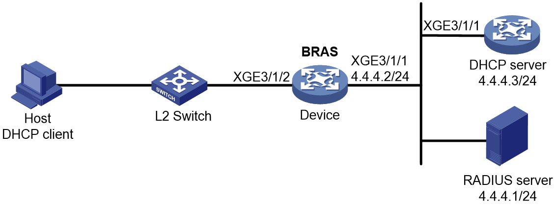
Prerequisites
Configure IP addresses for interfaces, and make sure devices can reach each other at Layer 3. (Details not shown.)
Procedure
1. Configure the RADIUS server:
# Add BRAS IP address 4.4.4.2 and secret radius to the clients.conf file.
client 4.4.4.2/32 {
ipaddr = 4.4.4.2
netmask=32
secret=radius
}
# Add the username and password to the users user information file. The username is the host MAC address and the password is radius.
000c29a6b656 Cleartext-Password :="radius"
2. Configure the DHCP server:
# Enable DHCP.
<DHCP-server> system-view
[DHCP-server] dhcp enable
# Enable the DHCP server to return a DHCP-NAK message if the client notions of their IP addresses are incorrect.
[DHCP-server] dhcp server request-ip-address check
# Create an IP address pool named pool1 and enter its view.
[DHCP-server] ip pool pool1
# Specify the subnet 3.3.3.0/24 for dynamic allocation and DNS server 8.8.8.8 in the pool.
[DHCP-server-ip-pool-pool1] network 3.3.3.0 24
[DHCP-server-ip-pool-pool1] dns-list 8.8.8.8
# Specify gateway address 3.3.3.1 in the address pool.
[DHCP-server-ip-pool-pool1] gateway-list 3.3.3.1
# Exclude IP address 3.3.3.1 from dynamic allocation in the pool.
[DHCP-server-ip-pool-pool1] forbidden-ip 3.3.3.1
[DHCP-server-ip-pool-pool1] quit
# Configure the default route.
[DHCP-server] ip route-static 0.0.0.0 0 4.4.4.2
3. Configure the BRAS:
a. Configure the DHCP relay agent:
# Enable DHCP.
<Device> system-view
[Device] dhcp enable
# Create a remote BAS IP address pool pool1, specify a gateway address in the address pool, exclude IP address 3.3.3.1 from dynamic allocation in the address pool, and specify a DHCP server for the address pool.
[Device] ip pool pool1 bas remote
[Device-ip-pool-pool1] gateway 3.3.3.1 24
[Device-ip-pool-pool1] forbidden-ip 3.3.3.1
[Device-ip-pool-pool1] remote-server 4.4.4.3
[Device-ip-pool-pool1] quit
b. Configure a RADIUS scheme:
# Create a RADIUS scheme named rs1 and enter its view.
[Device] radius scheme rs1
# Configure primary servers and keys for authentication and accounting.
[Device-radius-rs1] primary authentication 4.4.4.1
[Device-radius-rs1] primary accounting 4.4.4.1
[Device-radius-rs1] key authentication simple radius
[Device-radius-rs1] key accounting simple radius
# Exclude the ISP name from the username sent to the RADIUS server.
[Device-radius-rs1] user-name-format without-domain
[Device-radius-rs1] quit
c. Configure the ISP domain:
# Create an ISP domain named dm1 and enter its view.
[Device] domain name dm1
# Configure ISP domain dm1 to use RADIUS scheme rs1 and assign a remote BAS IP address pool.
[Device-isp-dm1] authentication ipoe radius-scheme rs1
[Device-isp-dm1] authorization ipoe radius-scheme rs1
[Device-isp-dm1] accounting ipoe radius-scheme rs1
[Device-isp-dm1] authorization-attribute ip-pool pool1
[Device-isp-dm1] quit
d. Configure IPoE:
# Enable IPoE and configure Layer 2 access mode on Ten-GigabitEthernet 3/1/2.
[Device] interface ten-gigabitethernet 3/1/2
[Device–Ten-GigabitEthernet3/1/2] ip subscriber l2-connected enable
# Enable unclassified-IP packet initiation on Ten-GigabitEthernet 3/1/2, and allow abnormally logged out DHCP client to come online again through IPv4 packet initiation.
[Device–Ten-GigabitEthernet3/1/2] ip subscriber initiator unclassified-ip enable matching-user
# Specify dm1 as the ISP domain for DHCP users.
[Device–Ten-GigabitEthernet3/1/2] ip subscriber dhcp domain dm1
# Configure plaintext password radius for authentication.
[Device–Ten-GigabitEthernet3/1/2] ip subscriber password plaintext radius
[Device–Ten-GigabitEthernet3/1/2] quit
Verifying the configuration
# Display IPoE session information to verify that the host has come online.
[Device] display access-user interface ten-gigabitethernet 3/1/2
UserID Interface IP address MAC address S-/C-VLAN
Username IPv6 address Access type
0x5c XGE3/1/2 3.3.3.2 000c-29a6-b656 -/-
000c29a6b656 - L2 IPoE dynamic
Example: Configuring DHCPv4 packet initiation (assigning an IP address pool group)
Network configuration
As shown in Figure 17, the host accesses the BRAS as a DHCP user. Users obtain IPv4 addresses from an address pool in the IP address pool group. The BRAS performs AAA for the host through the RADIUS server. This example uses the Linux Free RADIUS server.

Prerequisites
Configure IP addresses for interfaces, and make sure devices can reach each other at Layer 3. (Details not shown.)
Procedure
1. Configure the RADIUS server:
# Add BRAS IP address 4.4.4.2 and secret radius to the clients.conf file.
client 4.4.4.2/32 {
ipaddr = 4.4.4.2
netmask=32
secret=radius
}
# Add the usernames and passwords to the users user information file.
000c29a6b656 Cleartext-Password :="radius"
000c29a6b657 Cleartext-Password :="radius"
2. Configure the DHCP server:
# Enable DHCP.
<DHCP-server> system-view
[DHCP-server] dhcp enable
# Enable the DHCP server to return a DHCP-NAK message if the client notions of their IP addresses are incorrect.
[DHCP-server] dhcp server request-ip-address check
# Create an IP address pool named pool2 and enter its view.
[DHCP-server] ip pool pool2
# Specify the subnet 2.2.2.0/24 for dynamic allocation and DNS server 8.8.8.8 in the address pool.
[DHCP-server-ip-pool-pool2] network 2.2.2.0 24
[DHCP-server-ip-pool-pool2] dns-list 8.8.8.8
# Specify gateway address 2.2.2.1 in the address pool.
[DHCP-server-ip-pool-pool2] gateway-list 2.2.2.1
# Exclude IP address 2.2.2.1 from dynamic allocation in the address pool.
[DHCP-server-ip-pool-pool2] forbidden-ip 2.2.2.1
[DHCP-server-ip-pool-pool2] quit
# Create an IP address pool named pool3 and enter its view.
[DHCP-server] ip pool pool3
# Specify the subnet 3.3.3.0/24 for dynamic allocation and DNS server 8.8.8.8 in the pool.
[DHCP-server-ip-pool-pool3] network 3.3.3.0 24
[DHCP-server-ip-pool-pool3] dns-list 8.8.8.8
# Specify gateway address 3.3.3.1 in the address pool.
[DHCP-server-ip-pool-pool3] gateway-list 3.3.3.1
# Exclude IP address 3.3.3.1 from dynamic allocation in the pool.
[DHCP-server-ip-pool-pool3] forbidden-ip 3.3.3.1
[DHCP-server-ip-pool-pool3] quit
# Configure the default route.
[DHCP-server] ip route-static 0.0.0.0 0 4.4.4.2
3. Configure the BRAS:
a. Configure the DHCP relay agent:
# Enable DHCP.
<Device> system-view
[Device] dhcp enable
# Create a local BAS IP address pool pool1.
[Device] ip pool pool1 bas local
# Specify gateway address 1.1.1.1 and DNS server 8.8.8.8 in the address pool.
[Device-ip-pool-pool1] gateway 1.1.1.1 24
[Device-ip-pool-pool1] dns-list 8.8.8.8
# Exclude IP address 1.1.1.1 from dynamic allocation in the address pool.
[Device-ip-pool-pool1] forbidden-ip 1.1.1.1
[Device-ip-pool-pool1] quit
# Create a remote BAS IP address pool pool2, specify a gateway address in the address pool, exclude IP address 2.2.2.1 from dynamic allocation in the address pool, and specify a DHCP server for the address pool.
[Device] ip pool pool2 bas remote
[Device-ip-pool-pool2] gateway 2.2.2.1 24
[Device-ip-pool-pool2] forbidden-ip 2.2.2.1
[Device-ip-pool-pool2] remote-server 4.4.4.3
[Device-ip-pool-pool2] quit
# Create a remote BAS IP address pool pool3, specify a gateway address in the address pool, exclude IP address 3.3.3.1 from dynamic allocation in the address pool, and specify a DHCP server for the address pool.
[Device] ip pool pool3 bas remote
[Device-ip-pool-pool3] gateway 3.3.3.1 24
[Device-ip-pool-pool3] forbidden-ip 3.3.3.1
[Device-ip-pool-pool3] remote-server 4.4.4.3
[Device-ip-pool-pool3] quit
# Create IP address pool group poolgroup1, and assign local BAS IP address pool pool1 and remote BAS IP address pools pool2 and pool3 to the IP address pool group.
[Device] ip pool-group poolgroup1
[Device-ip-pool-group-poolgroup1] pool pool1
[Device-ip-pool-group-poolgroup1] pool pool2
[Device-ip-pool-group-poolgroup1] pool pool3
[Device-ip-pool-group-poolgroup1] quit
b. Configure a RADIUS scheme:
# Create a RADIUS scheme named rs1 and enter its view.
[Device] radius scheme rs1
# Configure primary servers and keys for authentication and accounting.
[Device-radius-rs1] primary authentication 4.4.4.1
[Device-radius-rs1] primary accounting 4.4.4.1
[Device-radius-rs1] key authentication simple radius
[Device-radius-rs1] key accounting simple radius
# Exclude the ISP name from the username sent to the RADIUS server.
[Device-radius-rs1] user-name-format without-domain
[Device-radius-rs1] quit
c. Configure the ISP domain:
# Create an ISP domain named dm1 and enter its view.
[Device] domain name dm1
# Configure ISP domain dm1 to use RADIUS scheme rs1 and assign an IP address pool group.
[Device-isp-dm1] authentication ipoe radius-scheme rs1
[Device-isp-dm1] authorization ipoe radius-scheme rs1
[Device-isp-dm1] accounting ipoe radius-scheme rs1
[Device-isp-dm1] authorization-attribute ip-pool-group poolgroup1
[Device-isp-dm1] quit
d. Configure IPoE:
# Enable IPoE and configure Layer 2 access mode on Ten-GigabitEthernet 3/1/2.
[Device] interface ten-gigabitethernet 3/1/2
[Device–Ten-GigabitEthernet3/1/2] ip subscriber l2-connected enable
# Specify ISP domain dm1 as the ISP domain for DHCP users.
[Device–Ten-GigabitEthernet3/1/2] ip subscriber dhcp domain dm1
# Configure plaintext password radius for authentication.
[Device–Ten-GigabitEthernet3/1/2] ip subscriber password plaintext radius
[Device–Ten-GigabitEthernet3/1/2] quit
Verifying the configuration
# After 253 users come online, display the statistics of the local DHCP address group pool1.
[Device] display dhcp server statistics pool pool1
Total IP addresses: 254
Free IP addresses: 0
Used: 253
Pool utilization: 100.00%
Bindings:
Automatic: 253
Manual: 0
Expired: 0
Conflicts: 0
The output shows that the usage of local DHCP address group pool1 is 100% and does not have allocable IP addresses.
When the resources in local IP address group pool1 are exhausted, the address resources on the DHCP server associated with remote BAS IP address pool pool2 are used to allocate IP addresses to new users.
Example: Configuring DHCPv6 packet initiation (assigning a remote IPv6 address pool)
Network configuration
As shown in Figure 18, the host accesses the BRAS as a DHCP user. It obtains configuration information from the DHCP server. The BRAS performs AAA for the host through the RADIUS server. This example uses the Linux Free RADIUS server.
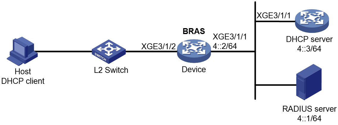
Prerequisites
Configure IP addresses for interfaces, and make sure devices can reach each other at Layer 3. (Details not shown.)
Procedure
1. Configure the RADIUS server:
# Add BRAS IP address 4::2 and secret radius to the clients.conf file.
client 4::2/64 {
ipaddr6 = 4::2
netmask=64
secret=radius
}
# Add the username and password to the users user information file. The username is the host MAC address and the password is radius.
000c29a6b656 Cleartext-Password :="radius"
2. Configure the DHCP server:
# Create an IPv6 address pool named pool1 and enter its view.
<DHCP-server> system-view
[DHCP-server] ipv6 pool pool1
# Specify the IPv6 subnet 3::/64 for dynamic allocation and specify DNS server 8::8 in the address pool pool1.
[DHCP-server-ipv6-pool-pool1] network 3::/64
[DHCP-server-ipv6-pool-pool1] dns-server 8::8
[DHCP-server-ipv6-pool-pool1] quit
# Enable the DHCPv6 server on Ten-GigabitEthernet 3/1/1.
[DHCP-server] interface ten-gigabitethernet 3/1/1
[DHCP-server-Ten-GigabitEthernet3/1/1] ipv6 dhcp select server
[DHCP-server-Ten-GigabitEthernet3/1/1] quit
# Configure the default route.
[DHCP-server] ipv6 route-static :: 0 4::2
3. Configure the BRAS:
a. Configure the DHCP relay agent:
# Create a remote IPv6 address pool pool1, specify a gateway address in the address pool, exclude IPv6 address 3::/64 from dynamic allocation in the address pool, and specify a DHCP server for the address pool.
<Device> system-view
[Device] ipv6 pool pool1
[Device-ipv6-pool-pool1] gateway-list 3::1
[Device-ipv6-pool-pool1] network 3::/64 export-route
[Device-ipv6-pool-pool1] remote-server 4::3
[Device-ipv6-pool-pool1] quit
# Enable the DHCPv6 relay agent on Ten-GigabitEthernet 3/1/2.
[Device] interface ten-gigabitethernet 3/1/2
[Device–Ten-GigabitEthernet3/1/2] ipv6 dhcp select relay
# Automatically generate a link-local address for Ten-GigabitEthernet 3/1/2.
[Device–Ten-GigabitEthernet3/1/2] ipv6 address auto link-local
# Disable RA message suppression on Ten-GigabitEthernet 3/1/2.
[Device–Ten-GigabitEthernet3/1/2] undo ipv6 nd ra halt
# Set the managed address configuration flag (M) to 1 in RA advertisements to be sent. Then, the host uses a DHCPv6 server to obtain IPv6 addresses.
[Device–Ten-GigabitEthernet3/1/2] ipv6 nd autoconfig managed-address-flag
# Set the other stateful configuration flag (O) to 1 in RA advertisements to be sent. Then, the host uses a DHCPv6 server to obtain configuration information other than IPv6 addresses.
[Device–Ten-GigabitEthernet3/1/2] ipv6 nd autoconfig other-flag
[Device–Ten-GigabitEthernet3/1/2] quit
b. Configure a RADIUS scheme:
# Create a RADIUS scheme named rs1 and enter its view.
[Device] radius scheme rs1
# Configure primary servers and keys for authentication and accounting.
[Device-radius-rs1] primary authentication ipv6 4::1
[Device-radius-rs1] primary accounting ipv6 4::1
[Device-radius-rs1] key authentication simple radius
[Device-radius-rs1] key accounting simple radius
# Exclude the ISP name from the username sent to the RADIUS server.
[Device-radius-rs1] user-name-format without-domain
[Device-radius-rs1] quit
c. Configure the ISP domain:
# Create an ISP domain named dm1 and enter its view.
[Device] domain name dm1
# Configure ISP domain dm1 to use RADIUS scheme rs1 and assign a remote IPv6 address pool.
[Device-isp-dm1] authentication ipoe radius-scheme rs1
[Device-isp-dm1] authorization ipoe radius-scheme rs1
[Device-isp-dm1] accounting ipoe radius-scheme rs1
[Device-isp-dm1] authorization-attribute ipv6-pool pool1
[Device-isp-dm1] quit
d. Configure IPoE:
# Enable IPoE and configure Layer 2 access mode on Ten-GigabitEthernet 3/1/2.
[Device] interface ten-gigabitethernet 3/1/2
[Device–Ten-GigabitEthernet3/1/2] ip subscriber l2-connected enable
# Specify dm1 as the ISP domain for DHCP users.
[Device–Ten-GigabitEthernet3/1/2] ip subscriber dhcp domain dm1
# Configure plaintext password radius for authentication.
[Device–Ten-GigabitEthernet3/1/2] ip subscriber password plaintext radius
[Device–Ten-GigabitEthernet3/1/2] quit
Verifying the configuration
# Display IPoE session information to verify that the host has come online and obtained IPv6 address 3::2.
[Device] display access-user interface ten-gigabitethernet 3/1/2
UserID Interface IP address MAC address S-/C-VLAN
Username IPv6 address Access type
0x2c2 XGE3/1/2 - 000c-29a6-b656 -/-
000c29a6b656 3::2 L2 IPoE dynamic
Example: Configuring IPv6 ND RS packet initiation (AAA-authorized prefix)
Network configuration
As shown in Figure 19, the host accesses the BRAS as an IPv6 ND RS user. The BRAS performs AAA for the host through the RADIUS server. This example uses the Linux Free RADIUS server.

Prerequisites
Configure IP addresses for interfaces, and make sure devices can reach each other at Layer 3. (Details not shown.)
Procedure
1. Configure the RADIUS server:
# Add BRAS IP address 4.4.4.2 and secret radius to the clients.conf file.
client 4.4.4.2/32 {
ipaddr = 4.4.4.2
netmask=32
secret=radius
}
# Add the username and password to the users user information file. The username is the host MAC address, and the password is radius.
000c29a6b656 Cleartext-Password :="radius"
2. Configure the BRAS:
a. Disable RA message suppression on Ten-GigabitEthernet 3/1/2.
<Device> system-view
[Device] interface ten-gigabitethernet 3/1/2
[Device–Ten-GigabitEthernet3/1/2] undo ipv6 nd ra halt
b. Automatically generate a link-local address for Ten-GigabitEthernet 3/1/2.
[Device–Ten-GigabitEthernet3/1/2] ipv6 address auto link-local
[Device–Ten-GigabitEthernet3/1/2] quit
c. Configure a RADIUS scheme:
# Create a RADIUS scheme named rs1 and enter its view.
[Device] radius scheme rs1
# Configure primary servers and keys for authentication and accounting.
[Device-radius-rs1] primary authentication 4.4.4.1
[Device-radius-rs1] primary accounting 4.4.4.1
[Device-radius-rs1] key authentication simple radius
[Device-radius-rs1] key accounting simple radius
# Exclude the ISP name from the username sent to the RADIUS server.
[Device-radius-rs1] user-name-format without-domain
[Device-radius-rs1] quit
d. (Applicable only to advertising prefix subnet routes.) Create an IPv6 address pool and enter its view. Specify the subnet for DHCPv6 clients and advertise the subnet route.
[Device] ipv6 pool pool1
[Device-ipv6-pool-pool1] network 10::/64 export-route
[Device-ipv6-pool-pool1] quit
e. Configure the ISP domain:
# Create an ISP domain named dm1 and enter its view.
[Device] domain name dm1
# Configure dm1 to use RADIUS scheme rs1.
[Device-isp-dm1] authentication ipoe radius-scheme rs1
[Device-isp-dm1] authorization ipoe radius-scheme rs1
[Device-isp-dm1] accounting ipoe radius-scheme rs1
# Authorize a IPv6 DNS address pool to users.
[Device-isp-dm1] authorization-attribute primary-dns ipv6 8::8
[Device-isp-dm1] quit
f. Configure IPoE:
# Enable IPoE and configure Layer 2 access mode on Ten-GigabitEthernet 3/1/2.
[Device] interface ten-gigabitethernet 3/1/2
[Device–Ten-GigabitEthernet3/1/2] ip subscriber l2-connected enable
# Enable IPv6 ND RS packet initiation on Ten-GigabitEthernet 3/1/2.
[Device–Ten-GigabitEthernet3/1/2] ip subscriber initiator ndrs enable
# Specify dm1 as the ISP domain for IPv6 ND RS users.
[Device–Ten-GigabitEthernet3/1/2] ip subscriber ndrs domain dm1
# Configure plaintext password radius for authentication.
[Device–Ten-GigabitEthernet3/1/2] ip subscriber password plaintext radius
[Device–Ten-GigabitEthernet3/1/2] quit
Verifying the configuration
# Display IPoE session information to verify that the host has come online.
[Device] display access-user interface ten-gigabitethernet 3/1/2
UserID Interface IP address MAC address S-/C-VLAN
Username IPv6 address Access type
0xc XGE3/1/2 - 000c-29a6-b656 -/-
000c29a6b656 10::20C:29FF:FEA6:B6 L2 IPoE dynamic
56
Example: Configuring IPv6 ND RS packet initiation (ND prefix pool-authorized prefix)
Network configuration
As shown in Figure 19, the host accesses the BRAS as an IPv6 ND RS user. The BRAS performs AAA for the host through the RADIUS server. This example uses the Linux Free RADIUS server.
Figure 20 Network diagram

Prerequisites
Configure IP addresses for interfaces, and make sure devices can reach each other at Layer 3. (Details not shown.)
Procedure
1. Configure the RADIUS server:
# Add BRAS IP address 4.4.4.2 and secret radius to the clients.conf file.
client 4.4.4.2/32 {
ipaddr = 4.4.4.2
netmask=32
secret=radius
}
# Add the username and password to the users user information file. The username is the host MAC address, and the password is radius.
000c29a6b656 Cleartext-Password :="radius"
2. Configure the BRAS:
a. Disable RA message suppression on Ten-GigabitEthernet 3/1/2.
<Device> system-view
[Device] interface ten-gigabitethernet 3/1/2
[Device–Ten-GigabitEthernet3/1/2] undo ipv6 nd ra halt
b. Automatically generate a link-local address for Ten-GigabitEthernet 3/1/2.
[Device–Ten-GigabitEthernet3/1/2] ipv6 address auto link-local
[Device–Ten-GigabitEthernet3/1/2] quit
c. Configure the ND prefix pool:
# Create prefix pool 1 that contains the prefix 10::/32 and specify the length of prefixes to be assigned as 64. Prefix pool 1 can assign 4294967296 prefixes in the range of 10::/64 to 10:0:FFFF:FFFF::/64.
[Device] ipv6 dhcp prefix-pool 1 prefix 10::/32 assign-len 64
# Create an IPv6 address pool named pool1, and reference prefix pool 1.
[Device] ipv6 pool pool1
[Device-ipv6-pool-pool1] prefix-pool 1 export-route
[Device-ipv6-pool-pool1] quit
d. Configure a RADIUS scheme:
# Create a RADIUS scheme named rs1 and enter its view.
[Device] radius scheme rs1
# Configure primary servers and keys for authentication and accounting.
[Device-radius-rs1] primary authentication 4.4.4.1
[Device-radius-rs1] primary accounting 4.4.4.1
[Device-radius-rs1] key authentication simple radius
[Device-radius-rs1] key accounting simple radius
# Exclude the ISP name from the username sent to the RADIUS server.
[Device-radius-rs1] user-name-format without-domain
[Device-radius-rs1] quit
e. Configure the ISP domain:
# Create an ISP domain named dm1 and enter its view.
[Device] domain name dm1
# Configure dm1 to use RADIUS scheme rs1, and authorize an ND prefix pool and IPv6 DNS address pool to users.
[Device-isp-dm1] authentication ipoe radius-scheme rs1
[Device-isp-dm1] authorization ipoe radius-scheme rs1
[Device-isp-dm1] accounting ipoe radius-scheme rs1
[Device-isp-dm1] authorization-attribute ipv6-nd-prefix-pool pool1
[Device-isp-dm1] authorization-attribute primary-dns ipv6 8::8
[Device-isp-dm1] quit
f. Configure IPoE:
# Enable IPoE and configure Layer 2 access mode on Ten-GigabitEthernet 3/1/2.
[Device] interface ten-gigabitethernet 3/1/2
[Device–Ten-GigabitEthernet3/1/2] ip subscriber l2-connected enable
# Enable IPv6 ND RS packet initiation on Ten-GigabitEthernet 3/1/2.
[Device–Ten-GigabitEthernet3/1/2] ip subscriber initiator ndrs enable
# Specify dm1 as the ISP domain for IPv6 ND RS users.
[Device–Ten-GigabitEthernet3/1/2] ip subscriber ndrs domain dm1
# Configure plaintext password radius for authentication.
[Device–Ten-GigabitEthernet3/1/2] ip subscriber password plaintext radius
[Device–Ten-GigabitEthernet3/1/2] quit
Verifying the configuration
# Display IPoE session information to verify that the host has come online.
[Device] display access-user interface ten-gigabitethernet 3/1/2
UserID Interface IP address MAC address S-/C-VLAN
Username IPv6 address Access type
0xc XGE3/1/2 - 000c-29a6-b656 -/-
000c29a6b656 10::20C:29FF:FEA6:B6 L2 IPoE dynamic
56
Example: Configuring IPv6 ND RS+DHCPv6 (IA_PD) initiation
Network configuration
As shown in Figure 21, the CPE supports applying for ND prefixes and PD prefixes from the BRAS through the following methods:
· NDRA—The CPE actively sends an ND RS packet to the BRAS. The BRAS returns an ND prefix to Ten-GigabitEthernet 3/1/1 on the connected CPE through an ND RA packet. The CPE uses the ND prefix to generate a global unicast IPv6 address for Ten-GigabitEthernet 3/1/1 on the CPE. The IPv6 address is used for remotely managing the CPE.
· IA_PD—The CPE actively sends DHCPv6 requests to the CPE. The BRAS allocates a PD prefix to the CPE through DHCPv6 (IA_PD). The CPE automatically allocates the obtained PD prefix to the attached hosts. These hosts use the PD prefix to generate global unicast IPv6 addresses.
Use the RADIUS server as the authentication, authorization, and accounting server.

Procedure
1. Configuring the RADIUS server:
This section uses the Linux Free RADIUS server as an example.
# Configure the RADIUS client IP address as 4.4.4.2 and configure the shared key as radius.
client 4.4.4.2/32 {
ipaddr = 4.4.4.2
netmask=32
secret=radius
}
# Add the username and password to the users user information file. The username is the host MAC address 6a4c310a0207 and the password is radius.
6a4c310a0207 Cleartext-Password :="radius"
2. Configure Router B:
a. Configure IP addresses for interfaces. (Details not shown.)
b. Disable RA message suppression on Ten-GigabitEthernet 3/1/2.
<RouterB> system-view
[RouterB] interface ten-gigabitethernet 3/1/2
[RouterB–Ten-GigabitEthernet3/1/2] undo ipv6 nd ra halt
c. Automatically generate a link-local address for Ten-GigabitEthernet 3/1/2.
[RouterB–Ten-GigabitEthernet3/1/2] ipv6 address auto link-local
d. Enable the DHCPv6 server on Ten-GigabitEthernet 3/1/2.
[RouterB–Ten-GigabitEthernet3/1/2] ipv6 dhcp select server
[RouterB–Ten-GigabitEthernet3/1/2] quit
e. Configure the ND prefix pool and PD prefix pool:
# (For NDRS.) Create prefix pool 1 that contains the prefix 10::/32 and specify the length of prefixes to be assigned as 64. Prefix pool 1 can assign 4294967296 prefixes in the range of 10::/64 to 10:0:FFFF:FFFF::/64.
[RouterB] ipv6 dhcp prefix-pool 1 prefix 10::/32 assign-len 64
# Create an IPv6 address pool named nd, and reference prefix pool 1.
[RouterB] ipv6 pool nd
[RouterB-ipv6-pool-nd] prefix-pool 1 export-route
[RouterB-ipv6-pool-nd] quit
# (For IA_PD.) Create prefix pool 2 that contains the prefix 20::/32 and specify the length of prefixes to be assigned as 64. Prefix pool 2 can assign 4294967296 prefixes in the range of 20::/64 to 20:0:FFFF:FFFF::/64.
[RouterB] ipv6 dhcp prefix-pool 2 prefix 20::/32 assign-len 64
# Create an IPv6 address pool named pd, and reference prefix pool 2.
[RouterB] ipv6 pool pd
[RouterB-ipv6-pool-pd] prefix-pool 2 export-route
[RouterB-ipv6-pool-pd] quit
f. Configure a RADIUS scheme:
# Create RADIUS scheme rs1, and enter its view.
[RouterB] radius scheme rs1
# Configure primary servers and keys for authentication and accounting.
[RouterB-radius-rs1] primary authentication 4.4.4.1
[RouterB-radius-rs1] primary accounting 4.4.4.1
[RouterB-radius-rs1] key authentication simple radius
[RouterB-radius-rs1] key accounting simple radius
# Exclude the ISP name from the username sent to the RADIUS server.
[RouterB-radius-rs1] user-name-format without-domain
[RouterB-radius-rs1] quit
g. Configuring ISP domains:
# Create ISP domain dm1, and enter its view.
[RouterB] domain name dm1
# Configure dm1 to use RADIUS scheme rs1, and authorize ND prefix pool nd and PD prefix pool pd to users.
[RouterB-isp-dm1] authentication ipoe radius-scheme rs1
[RouterB-isp-dm1] authorization ipoe radius-scheme rs1
[RouterB-isp-dm1] accounting ipoe radius-scheme rs1
[RouterB-isp-dm1] authorization-attribute ipv6-pool pd
[RouterB-isp-dm1] authorization-attribute ipv6-nd-prefix-pool nd
[RouterB-isp-dm1] quit
h. Configuring IPoE:
# Enable IPoE and configure Layer 2 access mode on Ten-GigabitEthernet 3/1/2.
[RouterB] interface ten-gigabitethernet 3/1/2
[RouterB–Ten-GigabitEthernet3/1/2] ip subscriber l2-connected enable
# Enable IPv6 ND RS packet initiation on Ten-GigabitEthernet 3/1/2.
[RouterB–Ten-GigabitEthernet3/1/2] ip subscriber initiator ndrs enable
# Specify dm1 as the ISP domain for IPv6 DHCP users on Ten-GigabitEthernet 3/1/2.
[RouterB–Ten-GigabitEthernet3/1/2] ip subscriber dhcp domain dm1
# Specify dm1 as the ISP domain for IPv6 ND RS users on Ten-GigabitEthernet 3/1/2.
[RouterB–Ten-GigabitEthernet3/1/2] ip subscriber ndrs domain dm1
# Allow users to come online through ND RS only after they come online through IA_PD on Ten-GigabitEthernet 3/1/2.
[RouterB–Ten-GigabitEthernet3/1/2] ip subscriber ndrs wait-delegation-prefix
# Configure plaintext password radius for authentication on Ten-GigabitEthernet 3/1/2.
[RouterB–Ten-GigabitEthernet3/1/2] ip subscriber password plaintext radius
[RouterB–Ten-GigabitEthernet3/1/2] quit
3. Configure Router A:
a. Automatically generate a link-local address for Ten-GigabitEthernet 3/1/1.
[RouterA] interface ten-gigabitethernet 3/1/1
[RouterA–Ten-GigabitEthernet3/1/1] ipv6 address auto
b. Configure Ten-GigabitEthernet 3/1/1 as the DHCPv6 client to use DHCPv6 to obtain an IPv6 prefix and other configuration parameters. After obtaining an IPv6 prefix, the client assigns ID 1 to the IPv6 prefix.
[RouterA–Ten-GigabitEthernet3/1/1] ipv6 dhcp client pd 1
[RouterA–Ten-GigabitEthernet3/1/1] quit
c. Configure the default route.
[RouterA] ipv6 route-static :: 0 10::1
d. Disable RA message suppression on Ten-GigabitEthernet 3/1/2.
[RouterA] interface ten-gigabitethernet 3/1/2
[RouterA-Ten-GigabitEthernet3/1/2] undo ipv6 nd ra halt
e. Configure Ten-GigabitEthernet 3/1/2 to use IPv6 prefix 1 to generate the IPv6 address 20::123:1:1 (which must be configured as the gateway address of the user attached to the CPE) and advertise this prefix.
[RouterA-Ten-GigabitEthernet3/1/2] ipv6 address 1 123::123:1:1/64
[RouterA-Ten-GigabitEthernet3/1/2] quit
Verifying the configuration
# The client uses ND RS and IA_PD packets to initiate authentication. After the client comes online, use the following command to view online IPoE user information. The output shows that the user obtains ND prefix 10:: and PD prefix 20::/64.
[RouterB] display access-user verbose
Basic:
Description: N/A
User ID: 0x1d
Username: 6a4c310a0207
Authorization domain : dm1
Authentication domain: dm1
Interface: XGE3/1/2
Service-VLAN/Customer-VLAN: -/-
VXLAN ID: -
MAC address: 6a4c-310a-0207
IP address: -
IP pool: -
Primary DNS server: -
Secondary DNS server: -
IPv6 address: 10::684C:31FF:FE0A:207
IPv6 pool: pd
Primary IPv6 DNS server: -
Secondary IPv6 DNS server: -
IPv6 PD prefix: 20::/64
IPv6 ND prefix: 10::/64
…Omitted…
The output shows that Router B assigns a PD prefix to Router A through DHCPv6.
# Display information about IPv6 prefixes created on Router A.
[RouterA] display ipv6 prefix
Number Prefix Type
1 20::/64 Dynamic
The output shows that Router A creates an IPv6 prefix with ID 1 according to the ipv6 dhcp client pd 1 command after obtaining a PD prefix from Router B.
Example: Configuring ARP packet initiation
Network configuration
As shown in Figure 22, an ARP-initiated static user accesses the BRAS through a Layer 2 device and is assigned the gateway IP address 3.3.3.1. The BRAS performs AAA for the host through the RADIUS server. This example uses the Linux Free RADIUS server.

Prerequisites
Configure IP addresses for interfaces, and make sure devices can reach each other at Layer 3. (Details not shown.)
Procedure
1. Configure the RADIUS server:
# Add BRAS IP address 4.4.4.2 and secret radius to the clients.conf file.
client 4.4.4.2/32 {
ipaddr = 4.4.4.2
netmask=32
secret=radius
}
# Add the username and password to the users user information file. The username is the host IP address 3.3.3.2. The password is radius.
3.3.3.2 Cleartext-Password :="radius"
2. Configure the BRAS:
a. Configure a RADIUS scheme:
# Create a RADIUS scheme named rs1 and enter its view.
<Device> system-view
[Device] radius scheme rs1
# Configure primary servers and keys for authentication and accounting.
[Device-radius-rs1] primary authentication 4.4.4.1
[Device-radius-rs1] primary accounting 4.4.4.1
[Device-radius-rs1] key authentication simple radius
[Device-radius-rs1] key accounting simple radius
# Exclude the ISP name from the username sent to the RADIUS server.
[Device-radius-rs1] user-name-format without-domain
[Device-radius-rs1] quit
b. Configure the ISP domain:
# Create an ISP domain named dm1 and enter its view.
[Device] domain name dm1
# Configure ISP domain dm1 to use RADIUS scheme rs1.
[Device-isp-dm1] authentication ipoe radius-scheme rs1
[Device-isp-dm1] authorization ipoe radius-scheme rs1
[Device-isp-dm1] accounting ipoe radius-scheme rs1
[Device-isp-dm1] quit
c. Configure the DHCP server.
# Enable DHCP globally.
[Device] dhcp enable
# Enable the DHCP server to return a DHCP-NAK message if the client notions of their IP addresses are incorrect.
[Device] dhcp server request-ip-address check
# Create local BAS IP address pool pool1, and specify the user gateway address. Exclude IP address 3.3.3.2 (which must be the IP address specified in static IPoE session configuration) from dynamic allocation.
[Device] ip pool pool1 bas local
[Device-ip-pool-pool1] gateway 3.3.3.1 24
[Device-ip-pool-pool1] forbidden-ip 3.3.3.2
[Device-ip-pool-pool1] quit
d. Configure IPoE:
# Enable IPoE and configure Layer 2 access mode on Ten-GigabitEthernet 3/1/2.
[Device] interface ten-gigabitethernet 3/1/2
[Device–Ten-GigabitEthernet3/1/2] ip subscriber l2-connected enable
# Enable ARP packet initiation on Ten-GigabitEthernet 3/1/2.
[Device–Ten-GigabitEthernet3/1/2] ip subscriber initiator arp enable
# Configure a static individual session with IP address 3.3.3.2 (which must be excluded from dynamic allocation in the IP address pool) and ISP domain dm1 on Ten-GigabitEthernet 3/1/2.
[Device–Ten-GigabitEthernet3/1/2] ip subscriber session static ip 3.3.3.2 domain dm1
# Configure plaintext password radius for authentication.
[Device–Ten-GigabitEthernet3/1/2] ip subscriber password plaintext radius
[Device–Ten-GigabitEthernet3/1/2] quit
Verifying the configuration
# Display IPoE session information to verify that the host has come online.
[Device] display access-user interface ten-gigabitethernet 3/1/2
UserID Interface IP address MAC address S-/C-VLAN
Username IPv6 address Access type
0x10 XGE3/1/2 3.3.3.2 147b-1924-0206 -/-
3.3.3.2 - L2 IPoE static
Example: Configuring NS/NA packet initiation
Network configuration
As shown in Figure 23, the host accesses the BRAS as a static NS/NA user. The BRAS performs AAA for the host through the RADIUS server. This example uses the Linux Free RADIUS server.

Prerequisites
Configure IP addresses for interfaces, and make sure devices can reach each other at Layer 3. (Details not shown.)
Procedure
1. Configure the RADIUS server:
# Add BRAS IP address 4::2 and secret radius to the clients.conf file.
client 4::2/64 {
ipaddr6 = 4::2
netmask=64
secret=radius
}
# Add the username and password to the users user information file. The username is the host IP address 3::1 and the password is radius.
3::1 Cleartext-Password :="radius"
2. Configure the BRAS:
a. Configure a RADIUS scheme:
# Create a RADIUS scheme named rs1 and enter its view.
<Device> system-view
[Device] radius scheme rs1
# Configure primary servers and keys for authentication and accounting.
[Device-radius-rs1] primary authentication ipv6 4::1
[Device-radius-rs1] primary accounting ipv6 4::1
[Device-radius-rs1] key authentication simple radius
[Device-radius-rs1] key accounting simple radius
# Exclude the ISP name from the username sent to the RADIUS server.
[Device-radius-rs1] user-name-format without-domain
[Device-radius-rs1] quit
b. Configure the ISP domain:
# Create an ISP domain named dm1 and enter its view.
[Device] domain name dm1
# Configure ISP domain dm1 to use RADIUS scheme rs1.
[Device-isp-dm1] authentication ipoe radius-scheme rs1
[Device-isp-dm1] authorization ipoe radius-scheme rs1
[Device-isp-dm1] accounting ipoe radius-scheme rs1
[Device-isp-dm1] quit
c. Configure the DHCP server:
# Create an IPv6 address pool, and enter its view. Specify a subnet for dynamic address allocation in the address pool, and exclude IPv6 address 3::1 from the address pool for dynamic allocation.
[Device] ipv6 pool pool1
[Device-ipv6-pool-pool1] network 3::/64 export-route
[Device-ipv6-pool-pool1] forbidden-address 3::1
[Device-ipv6-pool-pool1] quit
d. Configure IPoE:
# Automatically generate a link-local address for Ten-GigabitEthernet 3/1/2. The IPv6 address is to be used as the gateway of users.
[Device] interface ten-gigabitethernet 3/1/2
[Device–Ten-GigabitEthernet3/1/2] ipv6 address auto link-local
# Enable IPoE and configure Layer 2 access mode on Ten-GigabitEthernet 3/1/2.
[Device–Ten-GigabitEthernet3/1/2] ip subscriber l2-connected enable
# Enable NS/NA packet initiation on Ten-GigabitEthernet 3/1/2.
[Device–Ten-GigabitEthernet3/1/2] ip subscriber initiator nsna enable
# Create a static session with the IPv6 address 3::1 and authentication domain dm1.
[Device–Ten-GigabitEthernet3/1/2] ip subscriber session static ipv6 3::1 domain dm1
# Configure plaintext password radius for authentication.
[Device–Ten-GigabitEthernet3/1/2] ip subscriber password plaintext radius
[Device–Ten-GigabitEthernet3/1/2] quit
Verifying the configuration
# Display IPoE session information to verify that the host has come online.
[Device] display access-user interface Ten-GigabitEthernet 3/1/2
UserID Interface IP address MAC address S-/C-VLAN
Username IPv6 address Access type
0x4 XGE3/1/2 - 0010-9400-0002 -/-
3::1 3::1 L2 IPoE static
Example: Configuring unclassified-IP packet initiation for static IPoE users with IPv6 PD prefixes
Network configuration
As shown in Figure 24, Host A and Host B attached to the Layer 3 device Device use the same IPv6 address prefix (20::/64) and both obtain IPv6 addresses through stateless automatic configuration.
The BRAS uses the IPoE static user online method to enable all attached hosts to come online through IPv6 packets and performs unified authentication, accounting, rate limiting, and management for these user packets using the same IPv6 address prefix.
Use the RADIUS server as the authentication, authorization, and accounting server.
Network diagram
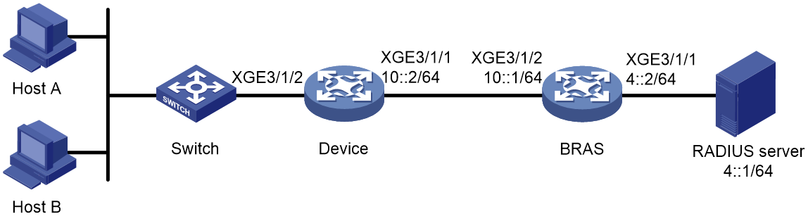
Prerequisites
Configure IP addresses for interfaces, and make sure devices can reach each other at Layer 3. (Details not shown.)
Procedure
1. Configure the RADIUS server:
|
|
NOTE: This section uses the Linux Free RADIUS server as an example. |
# Configure the RADIUS client.
Add the following contents to the clients.conf file.
client 4::2/64 {
ipaddr6 = 4::2
netmask=64
secret=radius
}
The contents above configure the RADIUS client IP address as 4::2 and configure the shared key as radius.
# Configure users.
Add the following contents to the users file:
10::2 Cleartext-Password :="radius"
# Add the username and password to the users user information file. The username is 10::2 and the password is radius.
2. Configure the BRAS:
a. Configure a RADIUS scheme:
# Create RADIUS scheme rs1, and enter its view.
<BRAS> system-view
[BRAS] radius scheme rs1
# Configure primary servers and keys for authentication and accounting.
[BRAS-radius-rs1] primary authentication ipv6 4::1
[BRAS-radius-rs1] primary accounting ipv6 4::1
[BRAS-radius-rs1] key authentication simple radius
[BRAS-radius-rs1] key accounting simple radius
# Exclude the ISP name from the username sent to the RADIUS server.
[BRAS-radius-rs1] user-name-format without-domain
[BRAS-radius-rs1] quit
b. Configure an ISP domain:
# Create ISP domain dm1, and enter its view.
[BRAS] domain name dm1
# Configure users to use RADIUS scheme rs1 for authentication, authorization, and accounting in the ISP domain.
[BRAS-isp-dm1] authentication ipoe radius-scheme rs1
[BRAS-isp-dm1] authorization ipoe radius-scheme rs1
[BRAS-isp-dm1] accounting ipoe radius-scheme rs1
[BRAS-isp-dm1] quit
c. Configure the DHCP server:
# Create a local BAS IP address pool named pool1. Specify the network for address allocation in the address pool. Exclude IPv6 address 10::2 (which must be the same as the user address specified in the IPoE static session) from the address pool for dynamic allocation.
[BRAS] ipv6 pool pool1
[BRAS-ipv6-pool-pool1] network 10::/64 export-route
[BRAS-ipv6-pool-pool1] forbidden-address 10::2
[BRAS-ip-pool-pool1] quit
d. Configure IPoE:
# Configure a global IPoE static session to allow users with IPv6 address 10::2 on prefix network segment 20::/64 to come online as static users, and configure the BRAS to actively request users to come online.
[BRAS] ip subscriber session static ipv6 10::2 delegation-prefix 20:: 64 domain dm1 interface ten-gigabitethernet 3/1/2 request-online
# Enter the view of interface Ten-GigabitEthernet3/1/2.
[BRAS] interface ten-gigabitethernet 3/1/2
# Enable IPoE and configure Layer 2 access mode.
[BRAS–Ten-GigabitEthernet3/1/2] ip subscriber l2-connected enable
# Enable unclassified-IPv6 packet initiation and NS/NA packet initiation.
[BRAS–Ten-GigabitEthernet3/1/2] ip subscriber initiator unclassified-ipv6 enable matching-user
[BRAS–Ten-GigabitEthernet3/1/2] ip subscriber initiator nsna enable
# Configure the password as radius for the IPoE individual users.
[BRAS–Ten-GigabitEthernet3/1/2] ip subscriber password plaintext radius
[BRAS–Ten-GigabitEthernet3/1/2] quit
3. Configure Device:
# Generate an IPv6 address based on an IPv6 prefix on the interface, and assign the prefix to endpoints.
<Device> system-view
[Device] ipv6 prefix 1 20::/64
[Device] interface ten-gigabitethernet 3/1/2
[Device–Ten-GigabitEthernet3/1/2] ipv6 address 1 ::1/64
# Disable RA message suppression.
[Device–Ten-GigabitEthernet3/1/2] undo ipv6 nd ra halt
[Device–Ten-GigabitEthernet3/1/2] quit
Verifying the configuration
# After Host A sends IPv6 packets and passes authentication, execute the following command to view online information of IPoE users.
[BRAS] display access-user interface ten-gigabitethernet 3/1/2
UserID Interface IP address MAC address S-/C-VLAN
Username IPv6 address Access type
0x4 XGE3/1/2 - 0010-9400-0002 -/-
10::2 10::2 L2 IPoE static
Example: Configuring subnet-leased users
Network configuration
As shown in Figure 25, three hosts access the BRAS as subnet-leased users. The BRAS performs AAA for the hosts through the RADIUS server. This example uses the Linux Free RADIUS server.
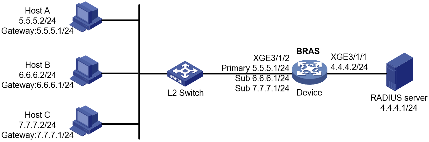
Prerequisites
Configure IP addresses for interfaces, and make sure devices can reach each other at Layer 3. (Details not shown.)
Procedure
1. Configure the RADIUS server:
# Add BRAS IP address 4.4.4.2 and secret radius to the clients.conf file.
client 4.4.4.2/32 {
ipaddr = 4.4.4.2
netmask=32
secret=radius
}
# Add usernames and passwords to the users user information file. Usernames for the three subnet user groups are us1, us2, and us3. Passwords for the three subnet user groups are pw1, pw2, and pw3.
us1 Cleartext-Password :="pw1"
us2 Cleartext-Password :="pw2"
us3 Cleartext-Password :="pw3"
2. Configure the BRAS:
a. Configure a RADIUS scheme:
# Create a RADIUS scheme named rs1 and enter its view.
<Device> system-view
[Device] radius scheme rs1
# Configure primary servers and keys for authentication and accounting.
[Device-radius-rs1] primary authentication 4.4.4.1
[Device-radius-rs1] primary accounting 4.4.4.1
[Device-radius-rs1] key authentication simple radius
[Device-radius-rs1] key accounting simple radius
# Exclude the ISP name from the username sent to the RADIUS server.
[Device-radius-rs1] user-name-format without-domain
[Device-radius-rs1] quit
b. Configure the ISP domain:
# Create an ISP domain named dm1 and enter its view.
[Device] domain name dm1
# Configure dm1 to use RADIUS scheme rs1.
[Device-isp-dm1] authentication ipoe radius-scheme rs1
[Device-isp-dm1] authorization ipoe radius-scheme rs1
[Device-isp-dm1] accounting ipoe radius-scheme rs1
[Device-isp-dm1] quit
c. Configure IPoE:
# Enable DHCP.
[Device] dhcp enable
# Enable IPoE and configure Layer 3 access mode on Ten-GigabitEthernet 3/1/2.
[Device] interface ten-gigabitethernet 3/1/2
[Device–Ten-GigabitEthernet3/1/2] ip subscriber routed enable
# Configure three subnet-leased users and specify their usernames, passwords, and ISP domains.
[Device–Ten-GigabitEthernet3/1/2] ip subscriber subnet-leased ip 5.5.5.0 24 username us1 password plaintext pw1 domain dm1
[Device–Ten-GigabitEthernet3/1/2] ip subscriber subnet-leased ip 6.6.6.0 24 username us2 password plaintext pw2 domain dm1
[Device–Ten-GigabitEthernet3/1/2] ip subscriber subnet-leased ip 7.7.7.0 24 username us3 password plaintext pw3 domain dm1
[Device–Ten-GigabitEthernet3/1/2] quit
Verifying the configuration
# Display IPoE session information to verify that the host has come online.
[Device] display access-user interface ten-gigabitethernet 3/1/2
UserID Interface IP address MAC address S-/C-VLAN
Username IPv6 address Access type
0x16 XGE3/1/2 5.5.5.0 - -/-
us1 - L3 IPoE subnet leased
0x17 XGE3/1/2 6.6.6.0 - -/-
us2 - L3 IPoE subnet leased
0x18 XGE3/1/2 7.7.7.0 - -/-
us3 - L3 IPoE subnet leased
Example: Configuring an interface-leased user
Network configuration
As shown in Figure 26, three hosts access the BRAS as one interface-leased user. The BRAS performs AAA for the hosts through the RADIUS server. This example uses the Linux Free RADIUS server.
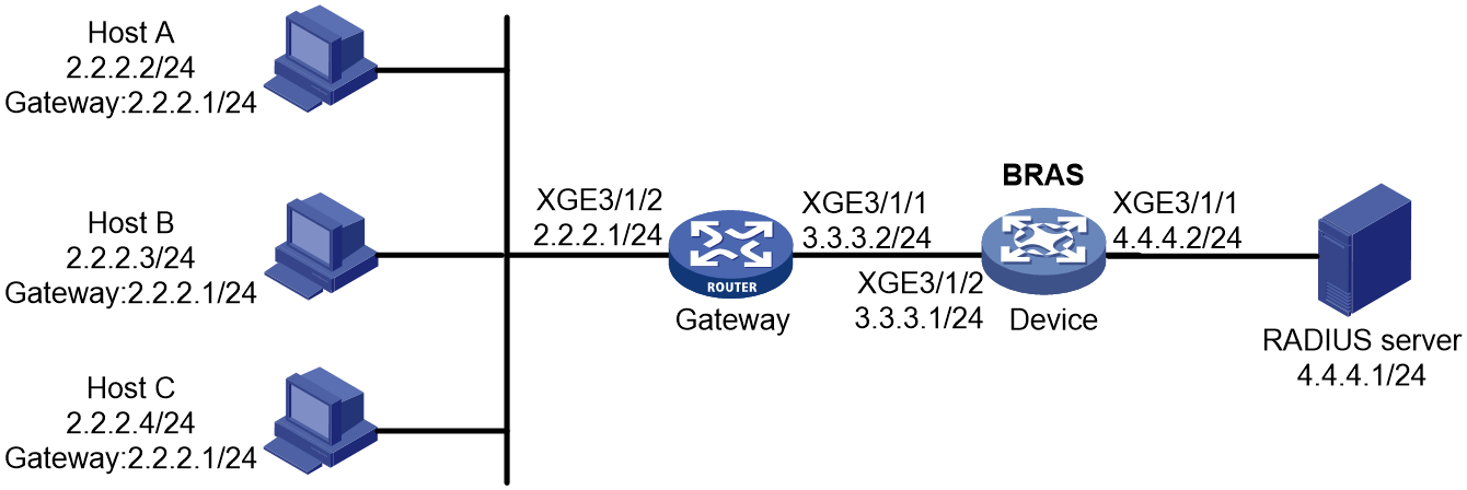
Prerequisites
Configure IP addresses for interfaces, and make sure devices can reach each other at Layer 3. (Details not shown.)
Procedure
1. Configure the RADIUS server:
# Add the BRAS IP address 4.4.4.2 and the secret radius to the clients.conf file.
client 4.4.4.2/32 {
ipaddr = 4.4.4.2
netmask=32
secret=radius
}
# Add host username and password to the users user information file. The username is us1 and the password is pw1.
us1 Cleartext-Password :="pw1"
2. Configure the BRAS:
a. Configure a RADIUS scheme:
# Create a RADIUS scheme named rs1 and enter its view.
<Device> system-view
[Device] radius scheme rs1
# Configure primary servers and keys for authentication and accounting.
[Device-radius-rs1] primary authentication 4.4.4.1
[Device-radius-rs1] primary accounting 4.4.4.1
[Device-radius-rs1] key authentication simple radius
[Device-radius-rs1] key accounting simple radius
# Exclude the ISP name from the username sent to the RADIUS server.
[Device-radius-rs1] user-name-format without-domain
[Device-radius-rs1] quit
b. Configure the ISP domain:
# Create an ISP domain named dm1 and enter its view.
[Device] domain name dm1
# Configure dm1 to use RADIUS scheme rs1.
[Device-isp-dm1] authentication ipoe radius-scheme rs1
[Device-isp-dm1] authorization ipoe radius-scheme rs1
[Device-isp-dm1] accounting ipoe radius-scheme rs1
[Device-isp-dm1] quit
c. Configure IPoE:
# Enable IPoE and configure Layer 3 access mode on Ten-GigabitEthernet 3/1/2.
[Device] interface ten-gigabitethernet 3/1/2
[Device–Ten-GigabitEthernet3/1/2] ip subscriber routed enable
# Configure the interface-leased user and specify its username, password, and ISP domain.
[Device–Ten-GigabitEthernet3/1/2] ip subscriber interface-leased username us1 password plaintext pw1 domain dm1
[Device–Ten-GigabitEthernet3/1/2] quit
Verifying the configuration
# Display IPoE session information to verify that the host has come online.
[Device] display access-user interface ten-gigabitethernet 3/1/2
UserID Interface IP address MAC address S-/C-VLAN
Username IPv6 address Access type
0xec XGE3/1/2 - - -/-
us1 - L3 IPoE interface leased
Example: Configuring an L2VPN-leased user
Network configuration
As shown in Figure 27, an L2VPN-leased host accesses the BRAS through a Layer 2 device. The BRAS performs AAA for the hosts through the RADIUS server. The username and password are us1 and pw1, respectively. This example uses the Linux Free RADIUS server.
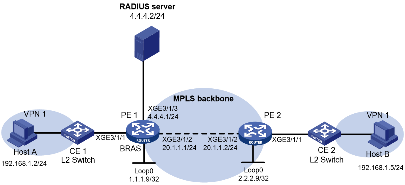
Prerequisites
Configure IP addresses for interfaces, and make sure devices can reach each other at Layer 3. (Details not shown.)
Procedure
1. Configure the RADIUS server:
# Add the BRAS IP address 4.4.4.2 and the secret radius to the clients.conf file.
client 4.4.4.2/32 {
ipaddr = 4.4.4.2
netmask=32
secret=radius
}
# Add host username and password to the users user information file. The username is us1 and the password is pw1.
us1 Cleartext-Password :="pw1"
2. Configure PE 2:
# Configure an LSR ID.
<PE2> system-view
[PE2] interface loopback 0
[PE2-LoopBack0] ip address 2.2.2.9 32
[PE2-LoopBack0] quit
[PE2] mpls lsr-id 2.2.2.9
# Enable L2VPN.
[PE2] l2vpn enable
# Enable LDP globally.
[PE2] mpls ldp
[PE2-ldp] quit
# Configure Ten-GigabitEthernet 3/1/2 (the interface connected to PE 1), and enable LDP on the interface.
[PE2] interface ten-gigabitethernet 3/1/2
[PE2-Ten-GigabitEthernet3/1/2] ip address 20.1.1.2 24
[PE2-Ten-GigabitEthernet3/1/2] mpls enable
[PE2-Ten-GigabitEthernet3/1/2] mpls ldp enable
[PE2-Ten-GigabitEthernet3/1/2] quit
# Configure OSPF for LDP to create LSPs.
[PE2] ospf
[PE2-ospf-1] area 0
[PE2-ospf-1-area-0.0.0.0] network 20.1.1.0 0.0.0.255
[PE2-ospf-1-area-0.0.0.0] network 2.2.2.9 0.0.0.0
[PE2-ospf-1-area-0.0.0.0] quit
[PE2-ospf-1] quit
# Create a VSI and configure the peer PE.
[PE2] vsi vpn1
[PE2-vsi-vpn1] pwsignaling static
[PE2-vsi-vpn1-static] peer 1.1.1.9 pw-id 3 in-label 100 out-label 100
[PE2-vsi-vpn1-static-1.1.1.9-3] quit
[PE2-vsi-vpn1-static] quit
[PE2-vsi-vpn1] quit
# Bind Ten-GigabitEthernet 3/1/1 to the VSI. Ten-GigabitEthernet 3/1/1 does not require IP address configuration.
[PE2] interface ten-gigabitethernet 3/1/1
[PE2-Ten-GigabitEthernet3/1/1] xconnect vsi vpn1
[PE2-Ten-GigabitEthernet3/1/1] quit
3. Configure PE1:
a. Configure VPLS:
# Configure an LSR ID.
<PE1> system-view
[PE1] interface loopback 0
[PE1-LoopBack0] ip address 1.1.1.9 32
[PE1-LoopBack0] quit
[PE1] mpls lsr-id 1.1.1.9
# Enable L2VPN.
[PE1] l2vpn enable
# Enable LDP globally.
[PE1] mpls ldp
[PE1-ldp] quit
# Configure Ten-GigabitEthernet 3/1/2 (the interface connected to PE 2), and enable LDP on the interface.
[PE1] interface ten-gigabitethernet 3/1/2
[PE1-Ten-GigabitEthernet3/1/2] ip address 20.1.1.1 24
[PE1-Ten-GigabitEthernet3/1/2] mpls enable
[PE1-Ten-GigabitEthernet3/1/2] mpls ldp enable
[PE1-Ten-GigabitEthernet3/1/2] quit
# Configure OSPF for LDP to create LSPs.
[PE1] ospf
[PE1-ospf-1] area 0
[PE1-ospf-1-area-0.0.0.0] network 20.1.1.0 0.0.0.255
[PE1-ospf-1-area-0.0.0.0] network 1.1.1.9 0.0.0.0
[PE1-ospf-1-area-0.0.0.0] quit
[PE1-ospf-1] quit
# Create a VSI and configure the peer PE.
[PE1] vsi vpn1
[PE1-vsi-vpn1] pwsignaling static
[PE1-vsi-vpn1-static] peer 2.2.2.9 pw-id 3 in-label 100 out-label 100
[PE1-vsi-vpn1-static-2.2.2.9-3] quit
[PE1-vsi-vpn1-static] quit
[PE1-vsi-vpn1] quit
# Bind Ten-GigabitEthernet 3/1/1 to the VSI. Ten-GigabitEthernet 3/1/1 does not require IP address configuration.
[PE1] interface ten-gigabitethernet 3/1/1
[PE1-Ten-GigabitEthernet3/1/1] xconnect vsi vpn1
[PE1-Ten-GigabitEthernet3/1/1] quit
b. Configure a RADIUS scheme:
# Create a RADIUS scheme named rs1 and enter its view.
<PE1> system-view
[PE1] radius scheme rs1
# Configure primary servers and keys for authentication and accounting.
[PE1-radius-rs1] primary authentication 4.4.4.1
[PE1-radius-rs1] primary accounting 4.4.4.1
[PE1-radius-rs1] key authentication simple radius
[PE1-radius-rs1] key accounting simple radius
# Exclude the ISP name from the username sent to the RADIUS server.
[PE1-radius-rs1] user-name-format without-domain
[PE1-radius-rs1] quit
c. Configure the ISP domain:
# Create an ISP domain named dm1 and enter its view.
[PE1] domain name dm1
# Configure ISP domain dm1 to use RADIUS scheme rs1.
[PE1-isp-dm1] authentication ipoe radius-scheme rs1
[PE1-isp-dm1] authorization ipoe radius-scheme rs1
[PE1-isp-dm1] accounting ipoe radius-scheme rs1
[PE1-isp-dm1] quit
d. Configure IPoE:
# Enable IPoE and configure Layer 2 access mode on Ten-GigabitEthernet 3/1/1.
[PE1] interface ten-gigabitethernet 3/1/1
[PE1–Ten-GigabitEthernet3/1/1] ip subscriber l2-connected enable
# Configure the L2VPN-leased user and specify the username, password, and ISP domain for the user.
[PE1–Ten-GigabitEthernet3/1/1] ip subscriber l2vpn-leased username us1 password plaintext pw1 domain dm1
[PE1–Ten-GigabitEthernet3/1/1] quit
Verifying the configuration
# Display IPoE session information to verify that the host has come online.
[PE1] display access-user interface ten-gigabitethernet 3/1/2
UserID Interface IP address MAC address S-/C-VLAN
Username IPv6 address Access type
0xec XGE3/1/1 - - -/-
us1 - IPoE L2VPN leased
Example: Configuring IPoE static leased users
Network configuration
All users on subnet 192.168.1.0/24 access the BRAS as IPoE static leased users through a gateway.
When the static leased session performs authentication, it uses username us1 and password pw1.
Use the RADIUS server as the authentication, authorization, and accounting server.
Network diagram
Figure 28 Network diagram

Prerequisites
Configure IP addresses for interfaces, and make sure devices can reach each other at Layer 3. (Details not shown.)
Procedure
1. Configure the RADIUS server:
|
|
NOTE: This section uses the Linux Free RADIUS server as an example. |
# Configure the RADIUS client.
Add the following contents to the clients.conf file.
client 4.4.4.2/32 {
ipaddr = 4.4.4.2
netmask=32
secret=radius
}
The contents above configure the RADIUS client IP address as 4.4.4.2 and configure the shared key as radius.
# Configure users.
Add the following contents to the users file:
us1 Cleartext-Password :="pw1"
# Add the username and password to the users user information file. The username is us1 and the password is pw1.
2. Configure the gateway device:
# Enable DHCP.
<Gateway> system-view
[Gateway] dhcp enable
# Configure IP address pool pool1 to allocate private network IPv4 addresses to internal network users.
[Gateway] ip pool pool1
[Gateway-ip-pool-pool1] network 192.168.1.0 24
[Gateway-ip-pool-pool1] gateway-list 192.168.1.1
[Gateway-ip-pool-pool1] dns-list 8.8.8.8
# Exclude IP address 192.168.1.1 from dynamic allocation.
[Gateway-ip-pool-pool1] forbidden-ip 192.168.1.1
[Gateway-ip-pool-pool1] quit
# Configure the IPv4 gateway address for internal network users on Ten-GigabitEthernet 3/1/2.
[Gateway] interface ten-gigabitethernet 3/1/2
[Gateway-Ten-GigabitEthernet3/1/2] ip address 192.168.1.1 24
# Configure an IPv6 global unicast address and disable RA message suppression on the interface.
[Gateway-Ten-GigabitEthernet3/1/2] ipv6 address 192::1/64
[Gateway-Ten-GigabitEthernet3/1/2] undo ipv6 nd ra halt
[Gateway-Ten-GigabitEthernet3/1/2] quit
# Enter the view of interface Ten-GigabitEthernet 3/1/1.
[Gateway] interface ten-gigabitethernet 3/1/1
# Configure an IPv4 address for the interface.
[Gateway-Ten-GigabitEthernet3/1/1] ip address 3.3.3.2 24
# (For IPv4.) Directly use the IP address of interface Ten-GigabitEthernet 3/1/1 to perform NAT for IP traffic from the internal network to the external network.
[Gateway-Ten-GigabitEthernet3/1/1] nat outbound
# Configure an IPv6 global multicast address for the interface.
[Gateway-Ten-GigabitEthernet3/1/1] ipv6 address 3::2/64
# Configure the default routes.
[Gateway] ip route-static 0.0.0.0 0 3.3.3.1 //The next hop is the shared gateway address
[Gateway] ipv6 route-static :: 0 3::1 //The next hop can be any IPv6 global unicast address on the same network segment as address 3::2/64 of interface Ten-GigabitEthernet3/1/1
3. Configure Device:
a. Configure IP addresses for interfaces. (Details not shown.)
b. Configuring a RADIUS scheme:
# Create RADIUS scheme rs1, and enter its view.
<Device> system-view
[Device] radius scheme rs1
# Configure primary servers and keys for authentication and accounting.
[Device-radius-rs1] primary authentication 4.4.4.1
[Device-radius-rs1] primary accounting 4.4.4.1
[Device-radius-rs1] key authentication simple radius
[Device-radius-rs1] key accounting simple radius
# Exclude the ISP name from the username sent to the RADIUS server.
[Device-radius-rs1] user-name-format without-domain
[Device-radius-rs1] quit
c. Configure an ISP domain:
# Create ISP domain dm1, and enter its view.
[Device] domain name dm1
# Configure users to use RADIUS scheme rs1 for authentication, authorization, and accounting in the ISP domain.
[Device-isp-dm1] authentication ipoe radius-scheme rs1
[Device-isp-dm1] authorization ipoe radius-scheme rs1
[Device-isp-dm1] accounting ipoe radius-scheme rs1
[Device-isp-dm1] quit
d. Configure the DHCP server:
# Enable DHCP globally.
[Device] dhcp enable
# Enable the DHCP server to return a DHCP-NAK message if the client notions of their IP addresses are incorrect.
[Device] dhcp server request-ip-address check
# Create an IPv4 address pool named pool1. Specify a gateway for the address pool. Exclude IP address 3.3.3.1 and 3.3.3.2 (which must be the same as the user addresses specified in the IPoE static sessions) from the address pool for dynamic allocation.
[Device] ip pool pool1 bas local
[Device-ip-pool-pool1] gateway 3.3.3.1 24
[Device-ip-pool-pool1] forbidden-ip 3.3.3.1 3.3.3.2
[Device-ip-pool-pool1] quit
# Create an IPv6 address pool named pool1. Specify a gateway for the address pool. Exclude IP address 3::1 and 3::2 (which must be the same as the user addresses specified in the IPoE static sessions) from the address pool for dynamic allocation.
[Device] ipv6 pool pool1
[Device-ipv6-pool-pool1] network 3::/64 export-route
[Device-ipv6-pool-pool1] forbidden-address 3::1 3::2
[Device-ipv6-pool-pool1] quit
e. Configure a static route for downlink traffic from the BRAS to the user side.
[Device] ipv6 route-static 192:: 64 3::2
f. Configure IPoE authentication:
# Configure a static leased session with IPv4 address 3.3.3.2, IPv6 address 3::2, and domain dm1, and actively request users to come online.
[Device] ip subscriber session static-leased ip 3.3.3.2 ipv6 3::2 interface GigabitEthernet 1/0/2 domain dm1 request-online
# Enter the view of interface Ten-GigabitEthernet3/1/2.
[Device] interface ten-gigabitethernet 3/1/2
# Automatically generate a link-local address for the interface.
[Device–Ten-GigabitEthernet3/1/2] ipv6 address auto link-local
# Enable IPoE and configure Layer 2 access mode.
[Device–Ten-GigabitEthernet3/1/2] ip subscriber l2-connected enable
[Device–Ten-GigabitEthernet3/1/2] quit
# Configure unclassified-IP packet initiation for IPoE static individual users.
[Device–Ten-GigabitEthernet3/1/2] ip subscriber initiator unclassified-ip enable matching-user
[Device–Ten-GigabitEthernet3/1/2] ip subscriber initiator unclassified-ipv6 enable matching-user
# Enable ARP packet initiation.
[Device–Ten-GigabitEthernet3/1/2] ip subscriber initiator arp enable
# Enable NS/NA packet initiation.
[Device–Ten-GigabitEthernet3/1/2] ip subscriber initiator nsna enable
# Configure the password as pw1 for the IPoE static individual us1.
[Device–Ten-GigabitEthernet3/1/2] ip subscriber username string us1
[Device–Ten-GigabitEthernet3/1/2] ip subscriber password plaintext pw1
# Disable online detection.
[Device–Ten-GigabitEthernet3/1/2] undo ip subscriber user-detect ip
[Device–Ten-GigabitEthernet3/1/2] undo ip subscriber user-detect ipv6
[Device–Ten-GigabitEthernet3/1/2] quit
Verifying the configuration
# After the static leased user passes authentication, all user traffic passing through the interface can be forwarded properly. Execute the following command to view online information of the IPoE static leased users.
[Device] display access-user interface ten-gigabitethernet 3/1/2
UserID Interface IP address MAC address S-/C-VLAN
Username IPv6 address Access type
0x5c XGE3/1/2 3.3.3.2 000c-29a6-b656 -/-
us1 3::2 L2 IPoE static
Example: Configuring a VPN DHCP user
Network configuration
As shown in Figure 29, the host in a VPN accesses the BRAS as a DHCP user. The BRAS performs AAA for the host through the RADIUS server. This example uses the Linux Free RADIUS server.
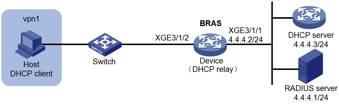
Configuration consideration
For traffic to be properly forwarded between VPNs, configure static routes and policy-based routes on the device.
Prerequisites
Configure IP addresses for interfaces, and make sure devices can reach each other at Layer 3. (Details not shown.)
Procedure
1. Configure the RADIUS server:
# Add BRAS IP address 4.4.4.2 and secret radius to the clients.conf file.
client 4.4.4.2/32 {
ipaddr = 4.4.4.2
netmask=32
secret=radius
}
# Add host username, password, VPN, and address pool to the users user information file. The username is the host MAC address, the password is radius, the VPN is vpn1, and the address pool is pool1.
000c29a6b656 Cleartext-Password :="radius"
H3C-VPN-Instance :="vpn1",
Framed-Pool := " pool1"
2. Configure the DHCP server:
# Enable DHCP.
<DHCP-server> system-view
[DHCP-server] dhcp enable
# Enable the DHCP server to return a DHCP-NAK message if the client notions of their IP addresses are incorrect.
[DHCP-server] dhcp server request-ip-address check
# Create an IP address pool named pool1 and enter its view.
[DHCP-server] ip pool pool1
# Specify the subnet 3.3.3.0/24 for dynamic allocation in the pool.
[DHCP-server-ip-pool-pool1] network 3.3.3.0 24
# Specify gateway address 3.3.3.1 in the address pool.
[DHCP-server-ip-pool-pool1] gateway-list 3.3.3.1
# Exclude IP address 3.3.3.1 from dynamic allocation in the pool.
[DHCP-server-ip-pool-pool1] forbidden-ip 3.3.3.1
[DHCP-server-ip-pool-pool1] quit
# Configure the default route.
[DHCP-server] ip route-static 0.0.0.0 0 4.4.4.2
3. Configure the BRAS:
a. Configure a RADIUS scheme:
# Create a RADIUS scheme named rs1 and enter its view.
<Device> system-view
[Device] radius scheme rs1
# Configure primary servers and keys for authentication and accounting.
[Device-radius-rs1] primary authentication 4.4.4.1
[Device-radius-rs1] primary accounting 4.4.4.1
[Device-radius-rs1] key authentication simple radius
[Device-radius-rs1] key accounting simple radius
# Exclude the ISP name from the username sent to the RADIUS server.
[Device-radius-rs1] user-name-format without-domain
[Device-radius-rs1] quit
b. Configure the ISP domain:
# Create an ISP domain named dm1 and enter its view.
[Device] domain name dm1
# Configure dm1 to use RADIUS scheme rs1.
[Device-isp-dm1] authentication ipoe radius-scheme rs1
[Device-isp-dm1] authorization ipoe radius-scheme rs1
[Device-isp-dm1] accounting ipoe radius-scheme rs1
[Device-isp-dm1] quit
c. Create a VPN instance named vpn1.
[Device] ip vpn-instance vpn1
[Device-vpn-instance-vpn1] quit
d. Configure the DHCP relay agent:
# Enable DHCP.
[Device] dhcp enable
# Enable the DHCP relay agent on Ten-GigabitEthernet 3/1/2.
[Device] interface ten-gigabitethernet 3/1/2
[Device–Ten-GigabitEthernet3/1/2] dhcp select relay
[Device–Ten-GigabitEthernet3/1/2] quit
# Create an address pool named pool1 and assign pool1 to vpn1.
[Device] ip pool pool1
[Device-ip-pool-pool1] vpn-instance vpn1
# Configure a gateway IP address for the host and enable route exporting. Route exporting automatically adds the gateway IP address and related static IP address to the routing table of vpn1.
[Device-ip-pool-pool1] gateway 3.3.3.1 24
# Exclude IP address 3.3.3.1 from dynamic allocation in the address pool.
[Device-ip-pool-pool1] forbidden-ip 3.3.3.1
# Configure an IP address for the DHCP sever
[Device-ip-pool-pool1] remote-server 4.4.4.3
[Device-ip-pool-pool1] quit
e. Configure IPoE:
# Enable IPoE and configure Layer 2 access mode on Ten-GigabitEthernet 3/1/2.
[Device] interface ten-gigabitethernet 3/1/2
[Device–Ten-GigabitEthernet3/1/2] ip subscriber l2-connected enable
# Specify dm1 as the ISP domain for DHCP users.
[Device–Ten-GigabitEthernet3/1/2] ip subscriber dhcp domain dm1
# Configure plaintext password radius for authentication.
[Device–Ten-GigabitEthernet3/1/2] ip subscriber password plaintext radius
f. Enable proxy ARP on Ten-GigabitEthernet 3/1/2.
[Device–Ten-GigabitEthernet3/1/2] proxy-arp enable
[Device–Ten-GigabitEthernet3/1/2] quit
g. Configure a static route to direct the DHCP requests from VPN vpn1 to the DHCP server.
[Device] ip route-static vpn-instance vpn1 4.4.4.0 24 4.4.4.3 public
h. Configure a policy-based route to direct the traffic from the DHCP server to VPN vpn1:
# Configure a policy named to_vpn1 with a node number of 0 and match mode of permit, and specify packets to be transmitted in VPN vpn1.
[Device] policy-based-route to_vpn1 permit node 0
[Device-pbr-to_vpn1-0] apply access-vpn vpn-instance vpn1
[Device-pbr-to_vpn1-0] quit
# Apply policy to_vpn1 to Ten-GigabitEthernet 3/1/1.
[Device] interface ten-gigabitethernet 3/1/1
[Device–Ten-GigabitEthernet3/1/1] ip policy-based-route to_vpn1
[Device–Ten-GigabitEthernet3/1/1] quit
Verifying the configuration
# Display IPoE session information to verify the configuration.
[Device]display access-user interface ten-gigabitethernet 3/1/2
UserID Interface IP address MAC address S-/C-VLAN
Username IPv6 address Access type
0xf8 XGE3/1/2 3.3.3.2 000c-29a6-b656 -/-
000c29a6b656 - L2 IPoE dynamic
Example: Configuring IPoE common Web authentication for static individual users
Network configuration
As shown in Figure 30, the host accesses the BRAS through a Layer 2 switch. A server installed with H3C IMC acts as the RADIUS server, the portal authentication server, and the portal Web server. This example uses IMC PLAT 7.1(E0303), IMC UAM 7.1(E0305), and IMC EIP 7.1(E0305). The FTP server is an internal network server.

Prerequisites
Configure IP addresses for interfaces, and make sure devices can reach each other at Layer 3. (Details not shown.)
Procedure
1. Configure the BRAS:
a. Configure the IP address of the portal authentication server newpt as 4.4.4.5 and the plaintext key 123456.
[Device] portal server newpt
[Device-portal-server-newpt] ip 4.4.4.5 key simple 123456
[Device-portal-server-newpt] quit
b. Specify 11111 as the HTTPS redirect listening port number. Make sure the port number is not used by any other service. To see the TCP port numbers used by other services, execute the display tcp command.
[Device] http-redirect https-port 11111
c. Configure the device to get user access information from ARP and ND entries.
[Device] portal access-info trust arp
[Device] portal access-info trust nd
d. Create a local user group named pre.
[Device] user-group pre
New user group added.
[Device-ugroup-pre] quit
e. Configure ACLs for preauthentication:
# Create an IPv4 advanced ACL named web_permit. Configure a rule to permit all packets destined for the portal server from users in user group pre.
[Device] acl advanced name web_permit
[Device-acl-ipv4-adv-web_permit] rule 0 permit ip destination 4.4.4.5 0 user-group pre
[Device-acl-ipv4-adv-web_permit] quit
# Create an IPv4 advanced ACL named neiwang. Configure a rule to permit all packets destined for the internal network server from users in user group pre.
[Device] acl advanced name neiwang
[Device-acl-ipv4-adv-neiwang] rule 0 permit ip destination 4.4.4.6 0 user-group pre
[Device-acl-ipv4-adv-neiwang] quit
# Create an IPv4 advanced ACL named web_http. Configure a rule to permit TCP packets with the destination port 80 (HTTP packets) from users in user group pre.
[Device] acl advanced name web_http
[Device-acl-ipv4-adv-web_http] rule 0 permit tcp destination-port eq www user-group pre
[Device-acl-ipv4-adv-web_http] quit
# Create an IPv4 advanced ACL named web_https, and configure a rule to permit TCP packets with the destination port 443 (HTTPS packets) from users in user group pre.
[Device] acl advanced name web_https
[Device-acl-ipv4-adv-web_https] rule 0 permit tcp destination-port eq 443 user-group pre
[Device-acl-ipv4-adv-web_https] quit
# Create an IPv4 advanced ACL named ip, and configure a rule to permit IP packets from users in user group pre.
[Device] acl advanced name ip
[Device-acl-ipv4-adv-ip] rule 0 permit ip user-group pre
[Device-acl-ipv4-adv-ip] quit
# Create an IPv4 advanced ACL named neiwang_out, and configure a rule to permit IP packets from the internal network server in user group pre.
[Device] acl advanced name neiwang_out
[Device-acl-ipv4-adv-neiwang_out] rule 0 permit ip source 4.4.4.4 0 user-group pre
[Device-acl-ipv4-adv-neiwang_out] quit
# Create an IPv4 advanced ACL named web_out, and configure a rule to permit IP packets from the portal server in user group pre.
[Device] acl advanced name web_out
[Device-acl-ipv4-adv-web_out] rule 0 permit ip source 4.4.4.5 0 user-group pre
[Device-acl-ipv4-adv-web_out] quit
f. Configure QoS traffic classes for preauthentication users:
# Create the traffic class web_permit and specify ACL web_permit as the match criterion.
[Device] traffic classifier web_permit operator and
[Device-classifier-web_permit] if-match acl name web_permit
[Device-classifier-web_permit] quit
# Create the traffic class neiwang and specify ACL neiwang as the match criterion.
[Device] traffic classifier neiwang operator and
[Device-classifier-neiwang] if-match acl name neiwang
[Device-classifier-neiwang] quit
# Create the traffic class web_http and specify ACL web_http as the match criterion.
[Device] traffic classifier web_http operator and
[Device-classifier-web_http] if-match acl name web_http
[Device-classifier-web_http] quit
# Create the traffic class web_https and specify ACL web_https as the match criterion.
[Device] traffic classifier web_https operator and
[Device-classifier-web_https] if-match acl name web_https
[Device-classifier-web_https] quit
# Create the traffic class web_deny and specify ACL ip as the match criterion.
[Device] traffic classifier web_deny operator and
[Device-classifier-web_deny] if-match acl name ip
[Device-classifier-web_deny] quit
# Create the traffic class neiwang_out and specify ACL neiwang_out as the match criterion.
[Device] traffic classifier neiwang_out operator and
[Device-classifier-neiwang_out] if-match acl name neiwang_out
[Device-classifier-neiwang_out] quit
# Create the traffic class web_out and specify ACL web_out as the match criterion.
[Device] traffic classifier web_out operator and
[Device-classifier-web_out] if-match acl name web_out
[Device-classifier-web_out] quit
g. Configure QoS traffic behaviors:
# Configure the traffic behavior web_permit to permit traffic to pass through without rate limiting or accounting.
[Device] traffic behavior web_permit
[Device-behavior-web_permit] filter permit
[Device-behavior-web_permit] free account
[Device-behavior-web_permit] quit
# Configure the traffic behavior neiwang to permit traffic to pass through.
[Device] traffic behavior neiwang
[Device-behavior-neiwang] filter permit
[Device-behavior-neiwang] quit
# Configure the traffic behavior web_http to redirect HTTP packets to the CPU.
[Device] traffic behavior web_http
[Device-behavior-web_http] redirect http-to-cpu
[Device-behavior-web_http] quit
# Configure the traffic behavior web_https to redirect HTTPS packets to the CPU.
[Device] traffic behavior web_https
[Device-behavior-web_https] redirect https-to-cpu
[Device-behavior-web_https] quit
# Configure the traffic behavior web_deny to deny traffic.
[Device] traffic behavior web_deny
[Device-behavior-web_deny] filter deny
[Device-behavior-web_deny] free account
[Device-behavior-web_deny] quit
# Configure the traffic behavior neiwang_out to permit traffic to pass through.
[Device] traffic behavior neiwang_out
[Device-behavior-neiwang_out] filter permit
[Device-behavior-neiwang_out] quit
# Configure the traffic behavior web_out to permit traffic without rate limiting or traffic accounting.
[Device] traffic behavior web_out
[Device-behavior-web_out] filter permit
[Device-behavior-web_out] free account
[Device-behavior-web_out] quit
h. Configure the QoS policies:
# Create a QoS policy named web.
[Device] qos policy web
# Associate the traffic class web_permit with the traffic behavior web_permit.
[Device-qospolicy-web] classifier web_permit behavior web_permit
# Associate the traffic class neiwang with the traffic behavior neiwang.
[Device-qospolicy-web] classifier neiwang behavior neiwang
# Associate the traffic class web_http with the traffic behavior web_http.
[Device-qospolicy-web] classifier web_http behavior web_http
# Associate the traffic class web_https with the traffic behavior web_https.
[Device-qospolicy-web] classifier web_https behavior web_https
# Associate the traffic class web_deny with the traffic behavior web_deny.
[Device-qospolicy-web] classifier web_deny behavior web_deny
[Device-qospolicy-web] quit
# Configure a QoS policy named out.
[Device] qos policy out
# Associate the traffic class web_out with the traffic behavior web_out. Associate the traffic class neiwang_out with the traffic behavior neiwang_out. Associate the traffic class web_deny with the traffic behavior web_deny.
[Device-qospolicy-out] classifier web_out behavior web_out
[Device-qospolicy-out] classifier neiwang_out behavior neiwang_out
[Device-qospolicy-out] classifier web_deny behavior web_deny
[Device-qospolicy-out] quit
i. Apply the QoS policies:
# Apply the QoS Policy web to the inbound traffic globally. To identify whether the QoS policy takes effect, execute the display qos policy global inbound command.
[Device] qos apply policy web global inbound
# Apply the QoS Policy out to the outbound traffic globally. To identify whether the QoS policy takes effect, execute the display qos policy global outbound command.
[Device] qos apply policy out global outbound
j. Configure a RADIUS scheme:
# Create a RADIUS scheme named rs1 and enter its view.
[Device] radius scheme rs1
# Configure primary servers and keys for authentication and accounting.
[Device-radius-rs1] primary authentication 4.4.4.5
[Device-radius-rs1] primary accounting 4.4.4.5
[Device-radius-rs1] key authentication simple radius
[Device-radius-rs1] key accounting simple radius
# Exclude the ISP name from the username sent to the RADIUS server.
[Device-radius-rs1] user-name-format without-domain
[Device-radius-rs1] quit
# (Optional.) Enable RADIUS session control. As a best practice, configure this feature when an IMC server acts as the RADIUS server.
[Device] radius session-control enable
k. Configure the preauthentication ISP domain and Web authentication ISP domain:
# Configure the ISP domain dm1 for IPoE user preauthentication.
[Device] domain name dm1
[Device-isp-dm1] authentication ipoe none
[Device-isp-dm1] authorization ipoe none
[Device-isp-dm1] accounting ipoe none
# Configure the authorized user group in ISP domain dm1.
[Device-isp-dm1] authorization-attribute user-group pre
# Configure the Web authentication page URL and Web server IP address in ISP domain dm1.
[Device-isp-dm1] web-server url http://4.4.4.5:8080/portal/
[Device-isp-dm1] web-server ip 4.4.4.5
[Device-isp-dm1] quit
# Configure the ISP domain dm2 for IPoE user Web authentication.
[Device] domain name dm2
[Device-isp-dm2] authentication ipoe radius-scheme rs1
[Device-isp-dm2] authorization ipoe radius-scheme rs1
[Device-isp-dm2] accounting ipoe radius-scheme rs1
[Device-isp-dm2] quit
l. Configure the DHCP server.
# Enable DHCP globally.
[Device] dhcp enable
# Enable the DHCP server to return a DHCP-NAK message if the client notions of their IP addresses are incorrect.
[Device] dhcp server request-ip-address check
# Create local BAS IP address pool pool1, and specify the user gateway address. Exclude IP address 192.168.0.2 (which must be the IP address specified in static IPoE session configuration) from dynamic allocation.
[Device] ip pool pool1 bas local
[Device-ip-pool-pool1] gateway 192.168.0.1 24
[Device-ip-pool-pool1] forbidden-ip 192.168.0.2
[Device-ip-pool-pool1] quit
m. Configure IPoE:
# Enable IPoE and configure Layer 2 access mode on Ten-GigabitEthernet 3/1/2.
[Device] interface ten-gigabitethernet 3/1/2
[Device–Ten-GigabitEthernet3/1/2] ip subscriber l2-connected enable
# Enable unclassified-IPv4 packet initiation.
[Device–Ten-GigabitEthernet3/1/2] ip subscriber initiator unclassified-ip enable matching-user
# Configure an IPoE static user with IP address 192.168.0.2, which must be excluded from dynamic allocation in the IP address pool.
[Device–Ten-GigabitEthernet3/1/2] ip subscriber session static ip 192.168.0.2
# Configure Web authentication for IPoE users on Ten-GigabitEthernet 3/1/2.
[Device–Ten-GigabitEthernet3/1/2] ip subscriber authentication-method web
The operation may cut all users on this interface. Continue?[Y/N]:y
# Configure the ISP domain dm1 for preauthentication and the ISP domain dm2 for Web authentication on Ten-GigabitEthernet 3/1/2.
[Device–Ten-GigabitEthernet3/1/2] ip subscriber pre-auth domain dm1
[Device–Ten-GigabitEthernet3/1/2] ip subscriber web-auth domain dm2
[Device–Ten-GigabitEthernet3/1/2] quit
2. Configure the RADIUS server:
a. Configure the access device:
- Log in to the IMC platform and click the User tab.
- Select User Access Policy > Access Device Management > Access Device from the navigation tree to open the access device configuration page.
- Click Add to open the page as shown in Figure 31.
- Enter the shared key radius.
- Use the default settings for other parameters.
Figure 31 Adding an access device

- Click Add Manually in the Device List area to open the page as shown in Figure 32.
- Enter the access device's IP address 4.4.4.2.
- Click OK.
Figure 32 Manually adding an access device

a. Add an access policy:
- Select User Access Policy > Access Policy from the navigation tree to open the access policy page.
- Click Add to open the page as shown in Figure 33.
- Enter the access policy name AccessPolicy.
- Use the default settings for other parameters.
Figure 33 Adding an access policy

a. Add an access service:
- Select User Access Policy > Access Service from the navigation tree to open the access service page.
- Click Add to open the page as shown in Figure 34.
- Enter the service name IPoE_Server.
- Select AccessPolicy from the default access policy list.
- Use the default settings for other parameters.
Figure 34 Adding an access service

a. Add a user:
- Select User Management > Add User from the navigation tree to open the adding user page, as shown in Figure 35.
- Enter the username IPoE_Web001 and the user ID 001.
- Click OK.
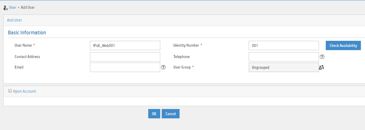
a. Add an access user:
- Select Access User > All Access Users from the navigation tree to open the access user page.
- Click Add to open the page as shown in Figure 36.
- Select IPoE_Web001 for the username.
- Enter the account name user1.
- Enter the password pass1.
- Select the access service IPoE_Server.
Figure 36 Adding an access user

3. Configure the portal server:
a. Configure the portal homepage:
- Select User Access Policy > Portal Service > Server from the navigation tree to open the portal server configuration page, as shown in Figure 37.
- Click OK.
Figure 37 Portal server configuration page

a. Configure portal authentication source IP address range:
- Select User Access Policy > Portal Service > IP Group from the navigation tree to open the portal IP address group configuration page.
- Click Add to open the page as shown in Figure 38.
- Enter the IP group name IPoE_Web_User.
- Enter the start IP address (192.168.0.1) and end IP address (192.168.0.255) of the IP group. Make sure the host IP address is in the IP group.
- Click OK.
Figure 38 Adding an IP address group

a. Add a portal device:
- Select User Access Policy > Portal Service > Device from the navigation tree to open the portal device configuration page.
- Click Add to open the page as shown in Figure 39.
- Enter the device name NAS.
- Enter the IP address of the portal packets' outgoing interface Ten-GigabitEthernet 3/1/1 (4.4.4.2).
- Enter the key 123456.
- Select Directly Connect for access method.
- Click OK.
Figure 39 Adding a portal device

a. Associate the portal device with the IP address group:
- Click the icon in the Port Group Information Management column of device NAS to open the port group configuration page, as shown in Figure 40.
- Click Add to open the page as shown in Figure 41.
- Enter the port group name group.
- Select the configured IP address group IPoE_Web_User. Make sure the IP address used by the user to access the network is within this IP address group.
- Click OK.

Figure 41 Port group configuration

Verifying the configuration
# Display IPoE session information to verify that the host has passed preauthentication.
UserID Interface IP address MAC address S-/C-VLAN
Username IPv6 address Access type
0x33d XGE3/1/2 192.168.0.2 0015-e947-f4d4 -/-
192.168.0.2 - L2 IPoE static
As shown in Figure 42, the Web login page opens after preauthentication. Enter the username and password on the page.

# Display IPoE session information to verify that the host has passed Web authentication and come online.
[Device] display access-user auth-type web-auth
UserID Interface IP address MAC address S-/C-VLAN
Username IPv6 address Access type
0x33d XGE3/1/2 192.168.0.2 0015-e947-f4d4 -/-
user1@dm2 - Web auth
Example: Configuring IPoE common Web authentication for DHCPv4 users (assigning a remote BAS IP address pool)
Network configuration
As shown in Figure 43, the host accesses the BRAS as a DHCP client through a Layer 2 device. It obtains configuration information from the DHCP server through the BRAS. The BRAS performs AAA for the host through the RADIUS server. A server installed with H3C IMC acts as the RADIUS server, the portal authentication server, and the portal Web server. The FTP server is an internal network server.
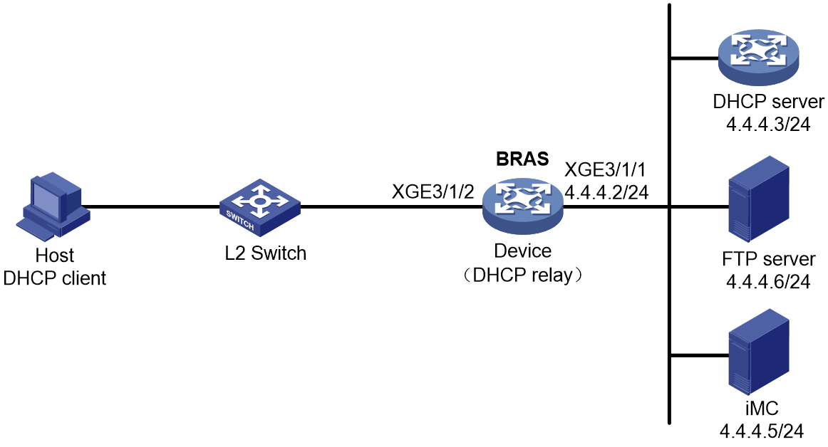
Prerequisites
Configure IP addresses for interfaces, and make sure devices can reach each other at Layer 3. (Details not shown.)
Procedure
1. Configure the DHCP server:
# Enable DHCP.
<DHCP-server> system-view
[DHCP-server] dhcp enable
# Enable the DHCP server to return a DHCP-NAK message if the client notions of their IP addresses are incorrect.
[DHCP-server] dhcp server request-ip-address check
# Create an IP address pool named pool1 and enter its view.
[DHCP-server] ip pool pool1
# Specify primary subnet 192.168.0.0/24 for dynamic allocation in address pool pool1.
[DHCP-server-ip-pool-pool1] network 192.168.0.0 24
# Specify gateway address 192.168.0.1 in address pool pool1.
[DHCP-server-ip-pool-pool1] gateway-list 192.168.0.1
# Specify DNS server address 8.8.8.8 in address pool pool1.
[DHCP-server-ip-pool-pool1] dns-list 8.8.8.8
# Exclude IP address 192.168.0.1 from dynamic allocation in address pool pool1.
[DHCP-server-ip-pool-pool1] forbidden-ip 192.168.0.1
[DHCP-server-ip-pool-pool1] quit
# Configure the default route.
[DHCP-server] ip route-static 0.0.0.0 0 4.4.4.2
2. Configure the BRAS:
a. Configure the DHCP relay agent:
# Enable DHCP.
<Device> system-view
[Device] dhcp enable
# Enable the DHCP relay agent on Ten-GigabitEthernet 3/1/2.
[Device] interface ten-gigabitethernet 3/1/2
[Device–Ten-GigabitEthernet3/1/2] dhcp select relay
[Device–Ten-GigabitEthernet3/1/2] quit
# Create a remote BAS IP address pool named pool1.
[Device] ip pool pool1 bas remote
# Specify gateway address 192.168.0.1 in address pool pool1.
[Device-ip-pool-pool1] gateway 192.168.0.1 24
# Exclude IP address 192.168.0.1 from dynamic allocation in address pool pool1.
[Device-ip-pool-pool1] forbidden-ip 192.168.0.1
# Specify DHCP server 4.4.4.3 in address pool pool1.
[Device-ip-pool-pool1] remote-server 4.4.4.3
[Device-ip-pool-pool1] quit
b. Configure the IP address of the portal authentication server newpt as 4.4.4.5 and the plaintext key 123456.
[Device] portal server newpt
[Device-portal-server-newpt] ip 4.4.4.5 key simple 123456
[Device-portal-server-newpt] quit
c. Specify 11111 as the HTTPS redirect listening port number. Make sure the port number is not used by any other service. To see the TCP port numbers used by other services, execute the display tcp command.
[Device] http-redirect https-port 11111
d. Configure the device to get user access information from ARP and ND entries.
[Device] portal access-info trust arp
[Device] portal access-info trust nd
e. Create a local user group named pre.
[Device] user-group pre
New user group added.
[Device-ugroup-pre] quit
f. Configure ACLs for preauthentication:
# Create an IPv4 advanced ACL named web_permit. Configure a rule to permit all packets destined for the portal server from users in user group pre.
[Device] acl advanced name web_permit
[Device-acl-ipv4-adv-web_permit] rule 0 permit ip destination 4.4.4.5 0 user-group pre
[Device-acl-ipv4-adv-web_permit] quit
# Create an IPv4 advanced ACL named neiwang. Configure a rule to permit all packets destined for the internal network server from users in user group pre.
[Device] acl advanced name neiwang
[Device-acl-ipv4-adv-neiwang] rule 0 permit ip destination 4.4.4.6 0 user-group pre
[Device-acl-ipv4-adv-neiwang] quit
# Create an IPv4 advanced ACL named web_http. Configure a rule to permit TCP packets with the destination port 80 (HTTP packets) from users in user group pre.
[Device] acl advanced name web_http
[Device-acl-ipv4-adv-web_http] rule 0 permit tcp destination-port eq www user-group pre
[Device-acl-ipv4-adv-web_http] quit
# Create an IPv4 advanced ACL named web_https, and configure a rule to permit TCP packets with the destination port 443 (HTTPS packets) from users in user group pre.
[Device] acl advanced name web_https
[Device-acl-ipv4-adv-web_https] rule 0 permit tcp destination-port eq 443 user-group pre
[Device-acl-ipv4-adv-web_https] quit
# Create an IPv4 advanced ACL named ip, and configure a rule to permit IP packets from users in user group pre.
[Device] acl advanced name ip
[Device-acl-ipv4-adv-ip] rule 0 permit ip user-group pre
[Device-acl-ipv4-adv-ip] quit
# Create an IPv4 advanced ACL named neiwang_out, and configure a rule to permit IP packets from the internal network server in user group pre.
[Device] acl advanced name neiwang_out
[Device-acl-ipv4-adv-neiwang_out] rule 0 permit ip source 4.4.4.4 0 user-group pre
[Device-acl-ipv4-adv-neiwang_out] quit
# Create an IPv4 advanced ACL named web_out, and configure a rule to permit IP packets from the portal server in user group pre.
[Device] acl advanced name web_out
[Device-acl-ipv4-adv-web_out] rule 0 permit ip source 4.4.4.5 0 user-group pre
[Device-acl-ipv4-adv-web_out] quit
g. Configure QoS traffic classes for preauthentication users:
# Create the traffic class web_permit and specify ACL web_permit as the match criterion.
[Device] traffic classifier web_permit operator and
[Device-classifier-web_permit] if-match acl name web_permit
[Device-classifier-web_permit] quit
# Create the traffic class neiwang and specify ACL neiwang as the match criterion.
[Device] traffic classifier neiwang operator and
[Device-classifier-neiwang] if-match acl name neiwang
[Device-classifier-neiwang] quit
# Create the traffic class web_http and specify ACL web_http as the match criterion.
[Device] traffic classifier web_http operator and
[Device-classifier-web_http] if-match acl name web_http
[Device-classifier-web_http] quit
# Create the traffic class web_https and specify ACL web_https as the match criterion.
[Device] traffic classifier web_https operator and
[Device-classifier-web_https] if-match acl name web_https
[Device-classifier-web_https] quit
# Create the traffic class web_deny and specify ACL ip as the match criterion.
[Device] traffic classifier web_deny operator and
[Device-classifier-web_deny] if-match acl name ip
[Device-classifier-web_deny] quit
# Create the traffic class neiwang_out and specify ACL neiwang_out as the match criterion.
[Device] traffic classifier neiwang_out operator and
[Device-classifier-neiwang_out] if-match acl name neiwang_out
[Device-classifier-neiwang_out] quit
# Create the traffic class web_out and specify ACL web_out as the match criterion.
[Device] traffic classifier web_out operator and
[Device-classifier-web_out] if-match acl name web_out
[Device-classifier-web_out] quit
h. Configure QoS traffic behaviors:
# Configure the traffic behavior web_permit to permit traffic to pass through without rate limiting or accounting.
[Device] traffic behavior web_permit
[Device-behavior-web_permit] filter permit
[Device-behavior-web_permit] free account
[Device-behavior-web_permit] quit
# Configure the traffic behavior neiwang to permit traffic to pass through.
[Device] traffic behavior neiwang
[Device-behavior-neiwang] filter permit
[Device-behavior-neiwang] quit
# Configure the traffic behavior web_http to redirect HTTP packets to the CPU.
[Device] traffic behavior web_http
[Device-behavior-web_http] redirect http-to-cpu
[Device-behavior-web_http] quit
# Configure the traffic behavior web_https to redirect HTTPS packets to the CPU.
[Device] traffic behavior web_https
[Device-behavior-web_https] redirect https-to-cpu
[Device-behavior-web_https] quit
# Configure the traffic behavior web_deny to deny traffic.
[Device] traffic behavior web_deny
[Device-behavior-web_deny] filter deny
[Device-behavior-web_deny] free account
[Device-behavior-web_deny] quit
# Configure the traffic behavior neiwang_out to permit traffic to pass through.
[Device] traffic behavior neiwang_out
[Device-behavior-neiwang_out] filter permit
[Device-behavior-neiwang_out] quit
# Configure the traffic behavior web_out to permit traffic without rate limiting or traffic accounting.
[Device] traffic behavior web_out
[Device-behavior-web_out] filter permit
[Device-behavior-web_out] free account
[Device-behavior-web_out] quit
i. Configure the QoS policies:
# Create a QoS policy named web.
[Device] qos policy web
# Associate the traffic class web_permit with the traffic behavior web_permit.
[Device-qospolicy-web] classifier web_permit behavior web_permit
# Associate the traffic class neiwang with the traffic behavior neiwang.
[Device-qospolicy-web] classifier neiwang behavior neiwang
# Associate the traffic class web_http with the traffic behavior web_http.
[Device-qospolicy-web] classifier web_http behavior web_http
# Associate the traffic class web_https with the traffic behavior web_https.
[Device-qospolicy-web] classifier web_https behavior web_https
# Associate the traffic class web_deny with the traffic behavior web_deny.
[Device-qospolicy-web] classifier web_deny behavior web_deny
[Device-qospolicy-web] quit
# Configure a QoS policy named out.
[Device] qos policy out
# Associate the traffic class web_out with the traffic behavior web_out. Associate the traffic class neiwang_out with the traffic behavior neiwang_out. Associate the traffic class web_deny with the traffic behavior web_deny.
[Device-qospolicy-out] classifier web_out behavior web_out
[Device-qospolicy-out] classifier neiwang_out behavior neiwang_out
[Device-qospolicy-out] classifier web_deny behavior web_deny
[Device-qospolicy-out] quit
j. Apply the QoS policies:
# Apply the QoS Policy web to the inbound traffic globally. To identify whether the QoS policy takes effect, execute the display qos policy global inbound command.
[Device] qos apply policy web global inbound
# Apply the QoS Policy out to the outbound traffic globally. To identify whether the QoS policy takes effect, execute the display qos policy global outbound command.
[Device] qos apply policy out global outbound
k. Configure a RADIUS scheme:
# Create a RADIUS scheme named rs1 and enter its view.
[Device] radius scheme rs1
# Configure primary servers and keys for authentication and accounting.
[Device-radius-rs1] primary authentication 4.4.4.5
[Device-radius-rs1] primary accounting 4.4.4.5
[Device-radius-rs1] key authentication simple radius
[Device-radius-rs1] key accounting simple radius
# Exclude the ISP name from the username sent to the RADIUS server.
[Device-radius-rs1] user-name-format without-domain
[Device-radius-rs1] quit
# (Optional.) Enable RADIUS session control. As a best practice, configure this feature when an IMC server acts as the RADIUS server.
[Device] radius session-control enable
l. Configure the preauthentication ISP domain and Web authentication ISP domain:
# Configure the ISP domain dm1 for IPoE user preauthentication.
[Device] domain name dm1
[Device-isp-dm1] authentication ipoe none
[Device-isp-dm1] authorization ipoe none
[Device-isp-dm1] accounting ipoe none
# Configure the authorized IP address pool and user group in preauthentication ISP domain dm1.
[Device-isp-dm1] authorization-attribute user-group pre
[Device-isp-dm1] authorization-attribute ip-pool pool1
# Configure the Web authentication page URL and Web server IP address in ISP domain dm1.
[Device-isp-dm1] web-server url http://4.4.4.5:8080/portal/
[Device-isp-dm1] web-server ip 4.4.4.5
[Device-isp-dm1] quit
# Configure the ISP domain dm2 for IPoE user Web authentication.
[Device] domain name dm2
[Device-isp-dm2] authentication ipoe radius-scheme rs1
[Device-isp-dm2] authorization ipoe radius-scheme rs1
[Device-isp-dm2] accounting ipoe radius-scheme rs1
[Device-isp-dm2] quit
m. Configure IPoE:
# Enable IPoE and configure Layer 2 access mode on Ten-GigabitEthernet 3/1/2.
[Device] interface ten-gigabitethernet 3/1/2
[Device–Ten-GigabitEthernet3/1/2] ip subscriber l2-connected enable
# Configure Web authentication for IPoE users on Ten-GigabitEthernet 3/1/2.
[Device–Ten-GigabitEthernet3/1/2] ip subscriber authentication-method web
The operation may cut all users on this interface. Continue?[Y/N]:y
# Configure the ISP domain dm1 for preauthentication and the ISP domain dm2 for Web authentication on Ten-GigabitEthernet 3/1/2.
[Device–Ten-GigabitEthernet3/1/2] ip subscriber pre-auth domain dm1
[Device–Ten-GigabitEthernet3/1/2] ip subscriber web-auth domain dm2
[Device–Ten-GigabitEthernet3/1/2] quit
3. Configure the RADIUS server:
a. Configure the access device:
- Log in to the IMC platform and click the User tab.
- Select User Access Policy > Access Device Management > Access Device from the navigation tree to open the access device configuration page.
- Click Add to open the page as shown in Figure 44.
- Enter the shared key radius.
- Use the default settings for other parameters.
Figure 44 Adding an access device

- Click Add Manually in the Device List area to open the page as shown in Figure 45.
- Enter the access device's IP address 4.4.4.2.
- Click OK.
Figure 45 Manually adding an access device

a. Add an access policy:
- Select User Access Policy > Access Policy from the navigation tree to open the access policy page.
- Click Add to open the page as shown in Figure 46.
- Enter the access policy name AccessPolicy.
- Use the default settings for other parameters.
Figure 46 Adding an access policy

a. Add an access service:
- Select User Access Policy > Access Service from the navigation tree to open the access service page.
- Click Add to open the page as shown in Figure 47.
- Enter the service name IPoE_Server.
- Select AccessPolicy from the default access policy list.
- Use the default settings for other parameters.
Figure 47 Adding an access service

a. Add a user:
- Select User Management > Add User from the navigation tree to open the adding user page, as shown in Figure 48.
- Enter the username IPoE_Web001 and the user ID 001.
- Click OK.

a. Add an access user:
- Select Access User > All Access Users from the navigation tree to open the access user page.
- Click Add to open the page as shown in Figure 49.
- Select IPoE_Web001 for the username.
- Enter the account name user1.
- Enter the password pass1.
- Select the access service IPoE_Server.
Figure 49 Adding an access user

4. Configure the portal server:
a. Configure the portal homepage:
- Select User Access Policy > Portal Service > Server from the navigation tree to open the portal server configuration page, as shown in Figure 50.
- Click OK.
Figure 50 Portal server configuration page
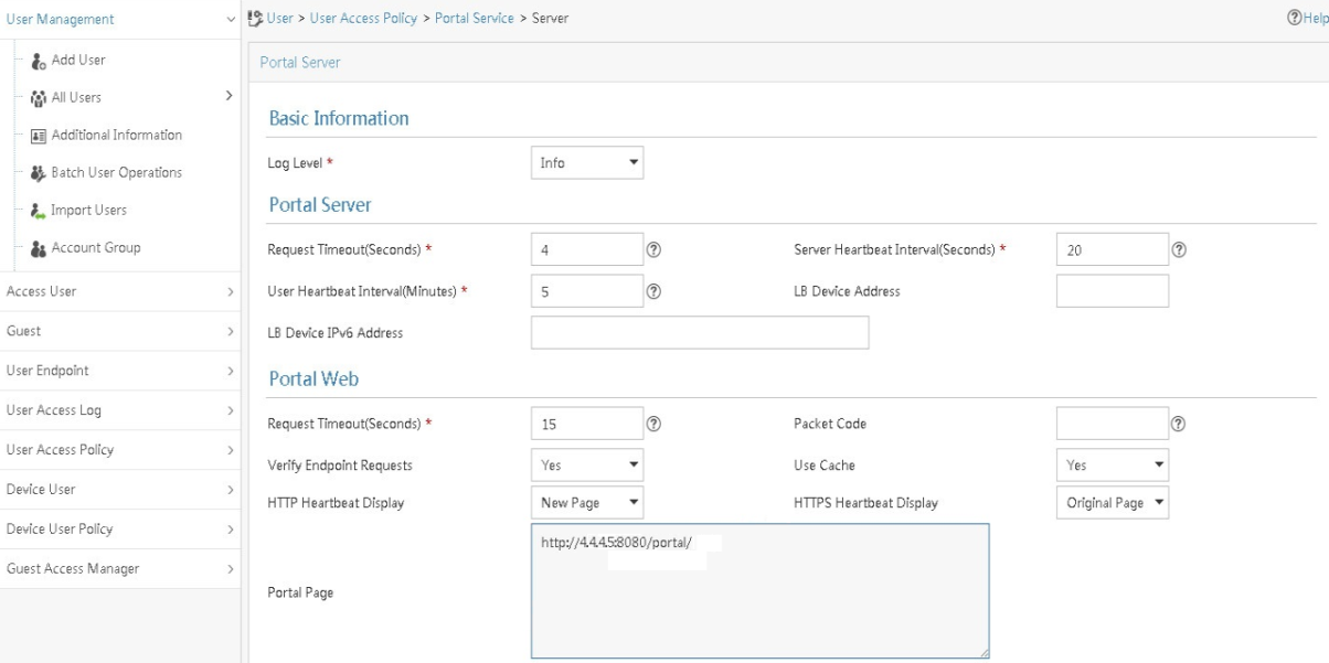
a. Configure portal authentication source IP address range:
- Select User Access Policy > Portal Service > IP Group from the navigation tree to open the portal IP address group configuration page.
- Click Add to open the page as shown in Figure 51.
- Enter the IP group name IPoE_Web_User.
- Enter the start IP address (192.168.0.1) and end IP address (192.168.0.255) of the IP group. Make sure the host IP address is in the IP group.
- Click OK.
Figure 51 Adding an IP address group

a. Add a portal device:
- Select User Access Policy > Portal Service > Device from the navigation tree to open the portal device configuration page.
- Click Add to open the page as shown in Figure 52.
- Enter the device name NAS.
- Enter the IP address of the portal packets' outgoing interface Ten-GigabitEthernet 3/1/1 (4.4.4.2).
- Enter the key 123456.
- Select Directly Connect for access method.
- Click OK.
Figure 52 Adding a portal device
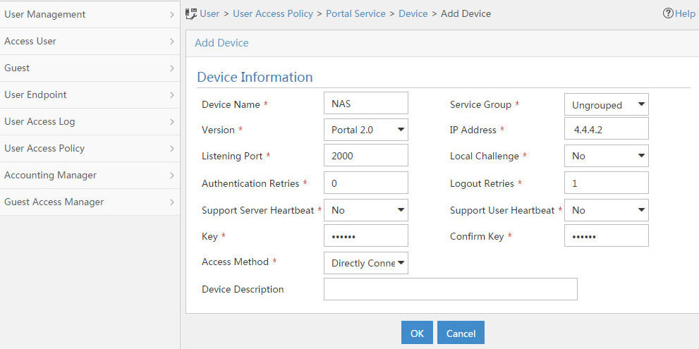
a. Associate the portal device with the IP address group:
- Click the icon in the Port Group Information Management column of device NAS to open the port group configuration page, as shown in Figure 53.
- Click Add to open the page as shown in Figure 54.
- Enter the port group name group.
- Select the configured IP address group IPoE_Web_User. Make sure the IP address used by the user to access the network is within this IP address group.
- Click OK.

Figure 54 Port group configuration

Verifying the configuration
# Display IPoE session information to verify that the host has passed preauthentication.
[Device] display access-user auth-type pre-auth
UserID Interface IP address MAC address S-/C-VLAN
Username IPv6 address Access type
0x33d XGE3/1/2 192.168.0.2 0015-e947-f4d4 -/-
0015e947f4d4 - L2 IPoE dynamic
As shown in Figure 55, the Web login page opens after preauthentication. Enter the username and password on the page.
# Display IPoE session information to verify that the host has passed Web authentication and come online.
[Device] display access-user auth-type web-auth
UserID Interface IP address MAC address S-/C-VLAN
Username IPv6 address Access type
0x33d XGE3/1/2 192.168.0.2 0015-e947-f4d4 -/-
user1@dm2 - Web auth
Example: Configuring IPoE common Web authentication for multi-network-segment DHCPv4 users (assigning a remote BAS IP address pool)
Network configuration
As shown in Figure 56:
· Host A belongs to VLAN 100 and resides on network segment 192.168.100.0/24, and comes online through Ten-GigabitEthernet 3/1/2.100 on the BRAS.
· Host B belongs to VLAN 200 and resides on network segment 192.168.200.0/24, and comes online through Ten-GigabitEthernet 3/1/2.200 on the BRAS.
· Host A and Host B access the BRAS as DHCP clients through a Layer 2 device. They obtain configuration information from the DHCP server through the BRAS.
· The BRAS performs AAA for the hosts through the RADIUS server.
· A server installed with H3C IMC acts as the RADIUS server, the portal authentication server, and the portal Web server.
· The FTP server is an internal network server.
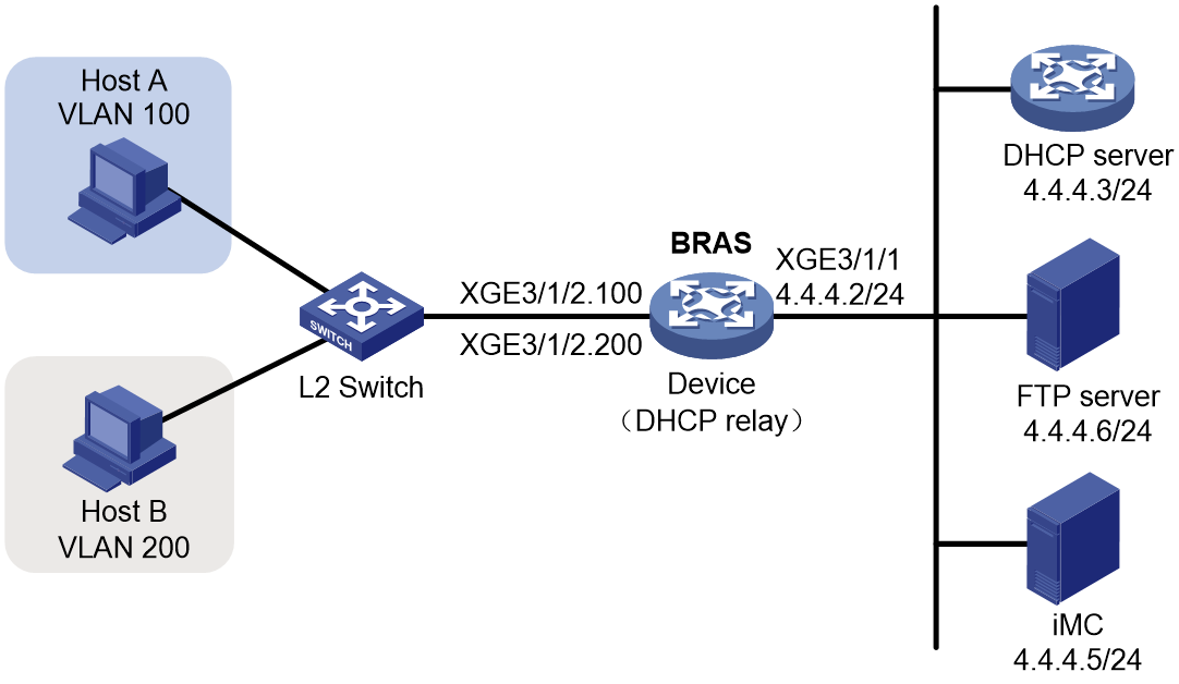
Prerequisites
Configure IP addresses for interfaces, and make sure devices can reach each other at Layer 3. (Details not shown.)
Procedure
1. Configure the DHCP server:
# Enable DHCP.
<DHCP-server> system-view
[DHCP-server] dhcp enable
# Enable the DHCP server to return a DHCP-NAK message if the client notions of their IP addresses are incorrect.
[DHCP-server] dhcp server request-ip-address check
# Create an IP address pool named pool1 and enter its view.
[DHCP-server] ip pool pool1
# Specify primary subnet 192.168.100.0/24 for dynamic allocation in address pool pool1.
[DHCP-server-ip-pool-pool1] network 192.168.100.0 24
# Specify gateway address 192.168.100.1 in address pool pool1.
[DHCP-server-ip-pool-pool1] gateway-list 192.168.100.1
# Specify DNS server address 8.8.8.8 in address pool pool1.
[DHCP-server-ip-pool-pool1] dns-list 8.8.8.8
# Exclude IP address 192.168.100.1 from dynamic allocation in address pool pool1.
[DHCP-server-ip-pool-pool1] forbidden-ip 192.168.100.1
[DHCP-server-ip-pool-pool1] quit
# Create an IP address pool named pool2 and enter its view.
[DHCP-server] ip pool pool2
# Specify primary subnet 192.168.200.0/24 for dynamic allocation in address pool pool2.
[DHCP-server-ip-pool-pool2] network 192.168.200.0 24
# Specify gateway address 192.168.200.1 in address pool pool2.
[DHCP-server-ip-pool-pool2] gateway-list 192.168.200.1
# Specify DNS server address 8.8.8.8 in address pool pool2.
[DHCP-server-ip-pool-pool2] dns-list 8.8.8.8
# Exclude IP address 192.168.200.1 from dynamic allocation in address pool pool2.
[DHCP-server-ip-pool-pool2] forbidden-ip 192.168.200.1
[DHCP-server-ip-pool-pool2] quit
# Configure the default route.
[DHCP-server] ip route-static 0.0.0.0 0 4.4.4.2
2. Configure the BRAS:
a. Configure the DHCP relay agent:
|
|
IMPORTANT: A DHCP relay address pool can be a remote BAS IP address pool or common IP address pool. In this example, the network segment 192.168.100.0/24 where host A resides uses remote BAS IP address pool pool1 as a relay address pool, and the network segment 192.168.200.0/24 where host B resides uses common IP address pool pool2 as a relay address pool. |
# Enable DHCP.
<Device> system-view
[Device] dhcp enable
# Create a remote BAS IP address pool named pool1.
[Device] ip pool pool1 bas remote
# Specify gateway address 192.168.100.1 in address pool pool1.
[Device-ip-pool-pool1] gateway 192.168.100.1 24
# Exclude IP address 192.168.100.1 from dynamic allocation in address pool pool1.
[Device-ip-pool-pool1] forbidden-ip 192.168.100.1
# Specify DHCP server 4.4.4.3 in address pool pool1.
[Device-ip-pool-pool1] remote-server 4.4.4.3
[Device-ip-pool-pool1] quit
# Create a common IP address pool named pool2.
[Device] ip pool pool2
# Specify network segment 192.168.200.1/24 for dynamic allocation in address pool pool2.
[Device-ip-pool-pool2] network 192.168.200.1 24 export-route
# Specify gateway address 192.168.200.1 in address pool pool2.
[Device-ip-pool-pool2] gateway-list 192.168.200.1 export-route
# Exclude IP address 192.168.200.1 from dynamic allocation in address pool pool2.
[Device-ip-pool-pool2] forbidden-ip 192.168.200.1
# Specify DHCP server 4.4.4.3 in address pool pool2.
[Device-ip-pool-pool2] remote-server 4.4.4.3
[Device-ip-pool-pool2] quit
# Assign IP address 192.168.100.1 to interface Ten-GigabitEthernet 3/1/2.100, enable the DHCP relay agent on the interface, and specify the DHCP server address 4.4.4.3.
[Device] interface ten-gigabitethernet 3/1/2.100
[Device–Ten-GigabitEthernet3/1/2.100] ip address 192.168.100.1 24
[Device–Ten-GigabitEthernet3/1/2.100] dhcp select relay
[Device–Ten-GigabitEthernet3/1/2.100] dhcp relay server-address 4.4.4.3
[Device–Ten-GigabitEthernet3/1/2.100] quit
# Assign IP address 192.168.200.1 to interface Ten-GigabitEthernet 3/1/2.200, enable the DHCP relay agent on the interface, and specify the DHCP server address 4.4.4.3.
[Device] interface ten-gigabitethernet 3/1/2.200
[Device–Ten-GigabitEthernet3/1/2.200] ip address 192.168.200.1 24
[Device–Ten-GigabitEthernet3/1/2.200] dhcp select relay
[Device–Ten-GigabitEthernet3/1/2.200] dhcp relay server-address 4.4.4.3
[Device–Ten-GigabitEthernet3/1/2.200] quit
b. Configure VLAN termination:
# Enable user mode of VLAN termination on Ten-GigabitEthernet 3/1/2.100 and Ten-GigabitEthernet 3/1/2.200. This feature prevents the subinterface restart and protects the online user state.
[Device] interface range ten-gigabitethernet 3/1/2.100 ten-gigabitethernet 3/1/2.200
[Device–if-range] vlan-termination user-mode
[Device–if-range] quit
# Configure Ten-GigabitEthernet 3/1/2.100 to terminate VLAN-tagged packets with the outermost VLAN tag as 100.
[Device] interface ten-gigabitethernet 3/1/2.100
[Device–Ten-GigabitEthernet3/1/2.100] user-vlan dot1q vid 100
[Device–Ten-GigabitEthernet3/1/2.100] quit
# Configure Ten-GigabitEthernet 3/1/2.200 to terminate VLAN-tagged packets with the outermost VLAN tag as 200.
[Device] interface ten-gigabitethernet 3/1/2.200
[Device–Ten-GigabitEthernet3/1/2.200] user-vlan dot1q vid 200
[Device–Ten-GigabitEthernet3/1/2.200] quit
c. Configure the IP address of the portal authentication server newpt as 4.4.4.5 and the plaintext key 123456.
[Device] portal server newpt
[Device-portal-server-newpt] ip 4.4.4.5 key simple 123456
[Device-portal-server-newpt] quit
d. Specify 11111 as the HTTPS redirect listening port number. Make sure the port number is not used by any other service. To see the TCP port numbers used by other services, execute the display tcp command.
[Device] http-redirect https-port 11111
e. Configure the device to get user access information from ARP and ND entries.
[Device] portal access-info trust arp
[Device] portal access-info trust nd
f. Create a local user group named pre.
[Device] user-group pre
New user group added.
[Device-ugroup-pre] quit
g. Configure ACLs for preauthentication:
# Create an IPv4 advanced ACL named web_permit. Configure a rule to permit all packets destined for the portal server from users in user group pre.
[Device] acl advanced name web_permit
[Device-acl-ipv4-adv-web_permit] rule 0 permit ip destination 4.4.4.5 0 user-group pre
[Device-acl-ipv4-adv-web_permit] quit
# Create an IPv4 advanced ACL named neiwang. Configure a rule to permit all packets destined for the internal network server from users in user group pre.
[Device] acl advanced name neiwang
[Device-acl-ipv4-adv-neiwang] rule 0 permit ip destination 4.4.4.4 0 user-group pre
[Device-acl-ipv4-adv-neiwang] quit
# Create an IPv4 advanced ACL named web_http. Configure a rule to permit TCP packets with the destination port 80 (HTTP packets) from users in user group pre.
[Device] acl advanced name web_http
[Device-acl-ipv4-adv-web_http] rule 0 permit tcp destination-port eq www user-group pre
[Device-acl-ipv4-adv-web_http] quit
# Create an IPv4 advanced ACL named web_https, and configure a rule to permit TCP packets with the destination port 443 (HTTPS packets) from users in user group pre.
[Device] acl advanced name web_https
[Device-acl-ipv4-adv-web_https] rule 0 permit tcp destination-port eq 443 user-group pre
[Device-acl-ipv4-adv-web_https] quit
# Create an IPv4 advanced ACL named ip, and configure a rule to permit IP packets from users in user group pre.
[Device] acl advanced name ip
[Device-acl-ipv4-adv-ip] rule 0 permit ip user-group pre
[Device-acl-ipv4-adv-ip] quit
# Create an IPv4 advanced ACL named neiwang_out, and configure a rule to permit IP packets from the internal network server in user group pre.
[Device] acl advanced name neiwang_out
[Device-acl-ipv4-adv-neiwang_out] rule 0 permit ip source 4.4.4.4 0 user-group pre
[Device-acl-ipv4-adv-neiwang_out] quit
# Create an IPv4 advanced ACL named web_out, and configure a rule to permit IP packets from the portal server in user group pre.
[Device] acl advanced name web_out
[Device-acl-ipv4-adv-web_out] rule 0 permit ip source 4.4.4.5 0 user-group pre
[Device-acl-ipv4-adv-web_out] quit
h. Configure QoS traffic classes for preauthentication users:
# Create the traffic class web_permit and specify ACL web_permit as the match criterion.
[Device] traffic classifier web_permit operator and
[Device-classifier-web_permit] if-match acl name web_permit
[Device-classifier-web_permit] quit
# Create the traffic class neiwang and specify ACL neiwang as the match criterion.
[Device] traffic classifier neiwang operator and
[Device-classifier-neiwang] if-match acl name neiwang
[Device-classifier-neiwang] quit
# Create the traffic class web_http and specify ACL web_http as the match criterion.
[Device] traffic classifier web_http operator and
[Device-classifier-web_http] if-match acl name web_http
[Device-classifier-web_http] quit
# Create the traffic class web_https and specify ACL web_https as the match criterion.
[Device] traffic classifier web_https operator and
[Device-classifier-web_https] if-match acl name web_https
[Device-classifier-web_https] quit
# Create the traffic class web_deny and specify ACL ip as the match criterion.
[Device] traffic classifier web_deny operator and
[Device-classifier-web_deny] if-match acl name ip
[Device-classifier-web_deny] quit
# Create the traffic class neiwang_out and specify ACL neiwang_out as the match criterion.
[Device] traffic classifier neiwang_out operator and
[Device-classifier-neiwang_out] if-match acl name neiwang_out
[Device-classifier-neiwang_out] quit
# Create the traffic class web_out and specify ACL web_out as the match criterion.
[Device] traffic classifier web_out operator and
[Device-classifier-web_out] if-match acl name web_out
[Device-classifier-web_out] quit
i. Configure QoS traffic behaviors:
# Configure the traffic behavior web_permit to permit traffic to pass through without rate limiting or accounting.
[Device] traffic behavior web_permit
[Device-behavior-web_permit] filter permit
[Device-behavior-web_permit] free account
[Device-behavior-web_permit] quit
# Configure the traffic behavior neiwang to permit traffic to pass through.
[Device] traffic behavior neiwang
[Device-behavior-neiwang] filter permit
[Device-behavior-neiwang] quit
# Configure the traffic behavior web_http to redirect HTTP packets to the CPU.
[Device] traffic behavior web_http
[Device-behavior-web_http] redirect http-to-cpu
[Device-behavior-web_http] quit
# Configure the traffic behavior web_https to redirect HTTPS packets to the CPU.
[Device] traffic behavior web_https
[Device-behavior-web_https] redirect https-to-cpu
[Device-behavior-web_https] quit
# Configure the traffic behavior web_deny to deny traffic.
[Device] traffic behavior web_deny
[Device-behavior-web_deny] filter deny
[Device-behavior-web_deny] free account
[Device-behavior-web_deny] quit
# Configure the traffic behavior neiwang_out to permit traffic to pass through.
[Device] traffic behavior neiwang_out
[Device-behavior-neiwang_out] filter permit
[Device-behavior-neiwang_out] quit
# Configure the traffic behavior web_out to permit traffic without rate limiting or traffic accounting.
[Device] traffic behavior web_out
[Device-behavior-web_out] filter permit
[Device-behavior-web_out] free account
[Device-behavior-web_out] quit
j. Configure the QoS policies:
# Create a QoS policy named web.
[Device] qos policy web
# Associate the traffic class web_permit with the traffic behavior web_permit.
[Device-qospolicy-web] classifier web_permit behavior web_permit
# Associate the traffic class neiwang with the traffic behavior neiwang.
[Device-qospolicy-web] classifier neiwang behavior neiwang
# Associate the traffic class web_http with the traffic behavior web_http.
[Device-qospolicy-web] classifier web_http behavior web_http
# Associate the traffic class web_https with the traffic behavior web_https.
[Device-qospolicy-web] classifier web_https behavior web_https
# Associate the traffic class web_deny with the traffic behavior web_deny.
[Device-qospolicy-web] classifier web_deny behavior web_deny
[Device-qospolicy-web] quit
# Configure a QoS policy named out.
[Device] qos policy out
# Associate the traffic class web_out with the traffic behavior web_out. Associate the traffic class neiwang_out with the traffic behavior neiwang_out. Associate the traffic class web_deny with the traffic behavior web_deny.
[Device-qospolicy-out] classifier web_out behavior web_out
[Device-qospolicy-out] classifier neiwang_out behavior neiwang_out
[Device-qospolicy-out] classifier web_deny behavior web_deny
[Device-qospolicy-out] quit
k. Apply the QoS policies:
# Apply the QoS Policy web to the inbound traffic globally. To identify whether the QoS policy takes effect, execute the display qos policy global inbound command.
[Device] qos apply policy web global inbound
# Apply the QoS Policy out to the outbound traffic globally. To identify whether the QoS policy takes effect, execute the display qos policy global outbound command.
[Device] qos apply policy out global outbound
l. Configure a RADIUS scheme:
# Create a RADIUS scheme named rs1 and enter its view.
[Device] radius scheme rs1
# Configure primary servers and keys for authentication and accounting.
[Device-radius-rs1] primary authentication 4.4.4.5
[Device-radius-rs1] primary accounting 4.4.4.5
[Device-radius-rs1] key authentication simple radius
[Device-radius-rs1] key accounting simple radius
# Exclude the ISP name from the username sent to the RADIUS server.
[Device-radius-rs1] user-name-format without-domain
[Device-radius-rs1] quit
# (Optional.) Enable RADIUS session control. As a best practice, configure this feature when an IMC server acts as the RADIUS server.
[Device] radius session-control enable
m. Configure the preauthentication ISP domain and Web authentication ISP domain:
# Configure the ISP domain dm1 for IPoE user preauthentication.
[Device] domain name dm1
[Device-isp-dm1] authentication ipoe none
[Device-isp-dm1] authorization ipoe none
[Device-isp-dm1] accounting ipoe none
# Configure the authorized user group in preauthentication ISP domain dm1.
[Device-isp-dm1] authorization-attribute user-group pre
# Configure the Web authentication page URL and Web server IP address in ISP domain dm1.
[Device-isp-dm1] web-server url http://4.4.4.5:8080/portal/
[Device-isp-dm1] web-server ip 4.4.4.5
[Device-isp-dm1] quit
# Configure the ISP domain dm2 for IPoE user Web authentication.
[Device] domain name dm2
[Device-isp-dm2] authentication ipoe radius-scheme rs1
[Device-isp-dm2] authorization ipoe radius-scheme rs1
[Device-isp-dm2] accounting ipoe radius-scheme rs1
[Device-isp-dm2] quit
n. Configure IPoE:
# Enable IPoE and configure Layer 2 access mode on subinterfaces Ten-GigabitEthernet 3/1/2.100 and Ten-GigabitEthernet 3/1/2.200.
[Device] interface range ten-gigabitethernet 3/1/2.100 ten-gigabitethernet 3/1/2.200
[Device–if-range] ip subscriber l2-connected enable
# Configure Web authentication for IPoE users on subinterfaces Ten-GigabitEthernet 3/1/2.100 and Ten-GigabitEthernet 3/1/2.200.
[Device–if-range] ip subscriber authentication-method web
The operation may cut all users on this interface. Continue?[Y/N]:y
# Configure the ISP domain dm1 for preauthentication and the ISP domain dm2 for Web authentication on subinterfaces Ten-GigabitEthernet 3/1/2.100 and Ten-GigabitEthernet 3/1/2.200.
[Device–if-range] ip subscriber pre-auth domain dm1
[Device–if-range] ip subscriber web-auth domain dm2
[Device–if-range] quit
3. Configure the RADIUS server and portal server.
For more information, see "Example: Configuring IPoE common Web authentication for DHCPv4 users (assigning a remote BAS IP address pool)."
Verifying the configuration
# Display IPoE session information to verify that hosts A and B have passed preauthentication.
[Device] display access-user auth-type pre-auth
UserID Interface IP address MAC address S-/C-VLAN
Username IPv6 address Access type
0x1 XGE3/1/2.100 192.168.100.2 0015-e947-f4d4 100/-
0015e947f4d4 - L2 IPoE dynamic
0x2 XGE3/1/2.200 192.168.200.2 0015-e947-f4d5 200/-
0015e947f4d5 - L2 IPoE dynamic
As shown in Figure 57, the Web login page opens after preauthentication. Enter the username and password on the page.

# Display IPoE session information to verify that the host has passed Web authentication and come online.
[Device] display access-user auth-type web-auth
UserID Interface IP address MAC address S-/C-VLAN
Username IPv6 address Access type
0x1 XGE3/1/2.100 192.168.100.2 0015-e947-f4d4 100/-
user1@dm2 - Web auth
0x2 XGE3/1/2.200 192.168.200.2 0015-e947-f4d5 200/-
user1@dm2 - Web auth
Example: Configuring IPoE common Web authentication for DHCPv6 users (assigning a remote IPv6 address pool)
Network configuration
As shown in Figure 58:
· The host accesses the BRAS as a DHCP client though a Layer 2 device.
· The host obtains configuration information from the DHCP server through the BRAS.
· The BRAS performs AAA for the host through the RADIUS server. A server installed with H3C IMC acts as the RADIUS server, the portal authentication server, and the portal Web server.
· The FTP server is an internal network server.
· Limit the access rate to 5 Mbps for the user after passing Web authentication.

Prerequisites
Configure the DNS server properly, so that the server can parse the IPv6 URL corresponding to the Web authentication page http://www.ipv6.web.com. (Details not shown.)
Configure IP addresses for interfaces and make sure the BRAS and servers can reach each other at Layer 3. (Details not shown.)
Procedure
1. Configure the DHCP server:
# Create an IPv6 address pool named pool1 and enter its view.
<DHCP-server> system-view
[DHCP-server] ipv6 pool pool1
# Specify primary subnet 192::/64 and DNS server address 8::8 for dynamic allocation in IPv6 address pool pool1.
[DHCP-server-ipv6-pool-pool1] network 192::/64
[DHCP-server-ipv6-pool-pool1] dns-server 8::8
[DHCP-server-ipv6-pool-pool1] quit
# Exclude IP address 192::1 from dynamic allocation in IPv6 address pool pool1.
[DHCP-server] ipv6 dhcp server forbidden-address 192::1
# Enable the DHCPv6 server on Ten-GigabitEthernet 3/1/1.
[DHCP] interface ten-gigabitethernet 3/1/1
[DHCP-server-Ten-GigabitEthernet3/1/1] ipv6 dhcp select server
[DHCP-server-Ten-GigabitEthernet3/1/1] quit
# Configure the default route.
[DHCP-server] ipv6 route-static :: 0 4::2
2. Configure the BRAS:
a. Configure the DHCP relay agent:
# Create an IP address pool named pool1 for the DHCP relay agent.
<Device> system-view
[Device] ipv6 pool pool1
# Specify gateway address 192::1 in IP address pool pool1.
[Device-ipv6-pool-pool1] gateway-list 192::1
# Specify network 192::/64 for address allocation in IP address pool pool1.
[Device-ipv6-pool-pool1] network 192::/64 export-route
# Specify DHCP server 4::3 in IP address pool pool1.
[Device-ipv6-pool-pool1] remote-server 4::3
[Device-ipv6-pool-pool1] quit
# Automatically generate a link-local address for Ten-GigabitEthernet 3/1/2.
[Device] interface ten-gigabitethernet 3/1/2
[Device–Ten-GigabitEthernet3/1/2] ipv6 address auto link-local
# Enable the DHCPv6 relay agent on Ten-GigabitEthernet 3/1/2.
[Device–Ten-GigabitEthernet3/1/2] ipv6 dhcp select relay
# Enable recording client information in DHCPv6 relay entries.
[Device–Ten-GigabitEthernet3/1/2] ipv6 dhcp relay client-information record
# Disable RA message suppression on Ten-GigabitEthernet 3/1/2.
[Device–Ten-GigabitEthernet3/1/2] undo ipv6 nd ra halt
# Set the managed address configuration flag (M) to 1 in RA advertisements to be sent. Then, the host uses a DHCPv6 server to obtain IPv6 addresses.
[Device–Ten-GigabitEthernet3/1/2] ipv6 nd autoconfig managed-address-flag
# Set the other stateful configuration flag (O) to 1 in RA advertisements to be sent. Then, the host uses a DHCPv6 server to obtain configuration information other than IPv6 addresses.
[Device–Ten-GigabitEthernet3/1/2] ipv6 nd autoconfig other-flag
# Disable Ten-GigabitEthernet 3/1/2 from advertising the specified prefix in RA messages, preventing the endpoint from obtaining a temporary IPv6 address. In an IPv6 network, an endpoint might use a temporary IPv6 address for IPoE Web authentication, which will cause authentication failure.
[Device–Ten-GigabitEthernet3/1/2] ipv6 nd ra prefix 192::/64 no-advertise
[Device–Ten-GigabitEthernet3/1/2] quit
b. Configure the IPv6 address of the IPv6 portal authentication server newpt1 as 4::5 and the plaintext key 123456.
[Device] portal server newpt1
[Device-portal-server-newpt1] ipv6 4::5 key simple 123456
[Device-portal-server-newpt1] quit
c. Specify 11111 as the HTTPS redirect listening port number. Make sure the port number is not used by any other service. To see the TCP port numbers used by other services, execute the display tcp command.
[Device] http-redirect https-port 11111
d. Configure the device to get user access information from ARP and ND entries.
[Device] portal access-info trust arp
[Device] portal access-info trust nd
e. Create a local user group named pre.
[Device] user-group pre
New user group added.
[Device-ugroup-pre] quit
f. Configure ACLs for preauthentication:
# Create an IPv6 advanced ACL named web_permit. Configure a rule to permit all packets destined for the portal server from users in user group pre.
[Device] acl ipv6 advanced name web_permit
[Device-acl-ipv6-adv-web_permit] rule 0 permit ipv6 destination 4::5 128 user-group pre
[Device-acl-ipv6-adv-web_permit] quit
# Create an IPv6 advanced ACL named neiwang. Configure a rule to permit all packets destined for the internal network server from users in user group pre.
[Device] acl ipv6 advanced name neiwang
[Device-acl-ipv6-adv-neiwang] rule 0 permit ipv6 destination 4::1 128 user-group pre
[Device-acl-ipv6-adv-neiwang] quit
# Create an IPv6 advanced ACL named web_http. Configure a rule to permit TCP packets with the destination port 80 (HTTP packets) from users in user group pre.
[Device] acl ipv6 advanced name web_http
[Device-acl-ipv6-adv-web_http] rule 0 permit tcp destination-port eq www user-group pre
[Device-acl-ipv6-adv-web_http] quit
# Create an IPv6 advanced ACL named web_https, and configure a rule to permit TCP packets with the destination port 443 (HTTPS packets) from users in user group pre.
[Device] acl ipv6 advanced name web_https
[Device-acl-ipv6-adv-web_https] rule 0 permit tcp destination-port eq 443 user-group pre
[Device-acl-ipv6-adv-web_https] quit
# Create an IPv6 advanced ACL named ip, and configure a rule to permit IP packets from users in user group pre.
[Device] acl ipv6 advanced name ip
[Device-acl-ipv6-adv-ip] rule 0 permit ipv6 user-group pre
[Device-acl-ipv6-adv-ip] quit
# Create an IPv6 advanced ACL named neiwang_out, and configure a rule to permit IP packets from the internal network server in user group pre.
[Device] acl ipv6 advanced name neiwang_out
[Device-acl-ipv6-adv-neiwang_out] rule 0 permit ipv6 source 4::1 128 user-group pre
[Device-acl-ipv6-adv-neiwang_out] quit
# Create an IPv6 advanced ACL named web_out, and configure a rule to permit IP packets from the portal server in user group pre.
[Device] acl ipv6 advanced name web_out
[Device-acl-ipv6-adv-web_out] rule 0 permit ipv6 source 4::5 128 user-group pre
[Device-acl-ipv6-adv-web_out] quit
g. Configure QoS traffic classes for preauthentication users:
# Create the traffic class web_permit and specify ACL web_permit as the match criterion.
[Device] traffic classifier web_permit operator or
[Device-classifier-web_permit] if-match acl ipv6 name web_permit
[Device-classifier-web_permit] quit
# Create the traffic class neiwang and specify ACL neiwang as the match criterion.
[Device] traffic classifier neiwang operator or
[Device-classifier-neiwang] if-match ipv6 acl name neiwang
[Device-classifier-neiwang] quit
# Create the traffic class web_http and specify ACL web_http as the match criterion.
[Device] traffic classifier web_http operator or
[Device-classifier-web_http] if-match ipv6 acl name web_http
[Device-classifier-web_http] quit
# Create the traffic class web_https and specify ACL web_https as the match criterion.
[Device] traffic classifier web_https operator or
[Device-classifier-web_https] if-match ipv6 acl name web_https
[Device-classifier-web_https] quit
# Create the traffic class web_deny and specify ACL ip as the match criterion.
[Device] traffic classifier web_deny operator or
[Device-classifier-web_deny] if-match ipv6 acl name ip
[Device-classifier-web_deny] quit
# Create the traffic class neiwang_out and specify ACL neiwang_out as the match criterion.
[Device] traffic classifier neiwang_out operator or
[Device-classifier-neiwang_out] if-match ipv6 acl name neiwang_out
[Device-classifier-neiwang_out] quit
# Create the traffic class web_out and specify ACL web_out as the match criterion.
[Device] traffic classifier web_out operator or
[Device-classifier-web_out] if-match ipv6 acl name web_out
[Device-classifier-web_out] quit
h. Configure QoS traffic behaviors:
# Configure the traffic behavior web_permit to permit traffic to pass through without rate limiting or accounting.
[Device] traffic behavior web_permit
[Device-behavior-web_permit] filter permit
[Device-behavior-web_permit] free account
[Device-behavior-web_permit] quit
# Configure the traffic behavior neiwang to permit traffic to pass through.
[Device] traffic behavior neiwang
[Device-behavior-neiwang] filter permit
[Device-behavior-neiwang] quit
# Configure the traffic behavior web_http to redirect HTTP packets to the CPU.
[Device] traffic behavior web_http
[Device-behavior-web_http] redirect http-to-cpu
[Device-behavior-web_http] quit
# Configure the traffic behavior web_https to redirect HTTPS packets to the CPU.
[Device] traffic behavior web_https
[Device-behavior-web_https] redirect https-to-cpu
[Device-behavior-web_https] quit
# Configure the traffic behavior web_deny to deny traffic.
[Device] traffic behavior web_deny
[Device-behavior-web_deny] filter deny
[Device-behavior-web_deny] free account
[Device-behavior-web_deny] quit
# Configure the traffic behavior neiwang_out to permit traffic to pass through.
[Device] traffic behavior neiwang_out
[Device-behavior-neiwang_out] filter permit
[Device-behavior-neiwang_out] quit
# Configure the traffic behavior web_out to permit traffic without rate limiting or traffic accounting.
[Device] traffic behavior web_out
[Device-behavior-web_out] filter permit
[Device-behavior-web_out] free account
[Device-behavior-web_out] quit
i. Configure the QoS policies:
# Create a QoS policy named web.
[Device] qos policy web
# Associate the traffic class web_permit with the traffic behavior web_permit.
[Device-qospolicy-web] classifier web_permit behavior web_permit
# Associate the traffic class neiwang with the traffic behavior neiwang.
[Device-qospolicy-web] classifier neiwang behavior neiwang
# Associate the traffic class web_http with the traffic behavior web_http.
[Device-qospolicy-web] classifier web_http behavior web_http
# Associate the traffic class web_https with the traffic behavior web_https.
[Device-qospolicy-web] classifier web_https behavior web_https
# Associate the traffic class web_deny with the traffic behavior web_deny.
[Device-qospolicy-web] classifier web_deny behavior web_deny
[Device-qospolicy-web] quit
# Configure a QoS policy named out.
[Device] qos policy out
# Associate the traffic class web_out with the traffic behavior web_out. Associate the traffic class neiwang_out with the traffic behavior neiwang_out. Associate the traffic class web_deny with the traffic behavior web_deny.
[Device-qospolicy-out] classifier web_out behavior web_out
[Device-qospolicy-out] classifier neiwang_out behavior neiwang_out
[Device-qospolicy-out] classifier web_deny behavior web_deny
[Device-qospolicy-out] quit
j. Apply the QoS policies:
# Apply the QoS Policy web to the inbound traffic globally. To identify whether the QoS policy takes effect, execute the display qos policy global inbound command.
[Device] qos apply policy web global inbound
# Apply the QoS Policy out to the outbound traffic globally. To identify whether the QoS policy takes effect, execute the display qos policy global outbound command.
[Device] qos apply policy out global outbound
k. Configure a RADIUS scheme:
# Create a RADIUS scheme named rs1 and enter its view.
[Device] radius scheme rs1
# Configure primary servers and keys for authentication and accounting.
[Device-radius-rs1] primary authentication ipv6 4::5
[Device-radius-rs1] primary accounting ipv6 4::5
[Device-radius-rs1] key authentication simple radius
[Device-radius-rs1] key accounting simple radius
# Exclude the ISP name from the username sent to the RADIUS server.
[Device-radius-rs1] user-name-format without-domain
[Device-radius-rs1] quit
# (Optional.) Enable RADIUS session control. As a best practice, configure this feature when an IMC server acts as the RADIUS server.
[Device] radius session-control enable
# Set the IP address of the RADIUS DAE client to 4::5, and set the shared key to radius for the RADIUS DAE client to exchange DAE packets.
[Device] radius dynamic-author server
[Device-radius-da-server] client ipv6 4::5 key simple radius
[Device-radius-da-server] quit
l. Configure the preauthentication ISP domain and Web authentication ISP domain:
# Configure the ISP domain dm1 for IPoE user preauthentication.
[Device] domain name dm1
[Device-isp-dm1] authentication ipoe none
[Device-isp-dm1] authorization ipoe none
[Device-isp-dm1] accounting ipoe none
# Configure the authorized user group and IPv6 address pool in preauthentication ISP domain dm1.
[Device-isp-dm1] authorization-attribute user-group pre
[Device-isp-dm1] authorization-attribute ipv6-pool pool1
# Configure the Web authentication page URL in ISP domain dm1.
[Device-isp-dm1] web-server ipv6-url http://www.ipv6.web.com
[Device-isp-dm1] quit
# Configure the ISP domain dm2 for IPoE user Web authentication.
[Device] domain name dm2
[Device-isp-dm2] authentication ipoe radius-scheme rs1
[Device-isp-dm2] authorization ipoe radius-scheme rs1
[Device-isp-dm2] accounting ipoe radius-scheme rs1
[Device-isp-dm2] authorization-attribute car inbound cir 5120 outbound cir 5120
[Device-isp-dm2] quit
m. Configure IPoE:
# Enable IPoE for the IPv6 protocol stack and configure Layer 2 access mode on Ten-GigabitEthernet 3/1/2.
[Device] interface ten-gigabitethernet 3/1/2
[Device–Ten-GigabitEthernet3/1/2] ip subscriber l2-connected enable ipv6
# Configure Web authentication for IPoE users on Ten-GigabitEthernet 3/1/2.
[Device–Ten-GigabitEthernet3/1/2] ip subscriber authentication-method web
The operation may cut all users on this interface. Continue?[Y/N]:y
# Configure the ISP domain dm1 for preauthentication and the ISP domain dm2 for Web authentication on Ten-GigabitEthernet 3/1/2.
[Device–Ten-GigabitEthernet3/1/2] ip subscriber pre-auth domain dm1
[Device–Ten-GigabitEthernet3/1/2] ip subscriber web-auth domain dm2
[Device–Ten-GigabitEthernet3/1/2] quit
3. Configure the RADIUS server:
a. Configure the access device:
- Log in to the IMC platform and click the User tab.
- Select User Access Policy > Access Device Management > Access Device from the navigation tree to open the access device configuration page.
- Click Add to open the page as shown in Figure 59.
- Enter the shared key radius.
- Use the default settings for other parameters.
Figure 59 Adding an access device
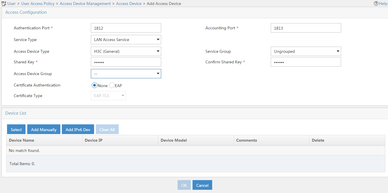
- Click Add IPv6 Dev in the Device List area to open the page as shown in Figure 60.
- Enter the access device's IPv6 address 4::2.
- Click OK.
Figure 60 Manually adding an access device
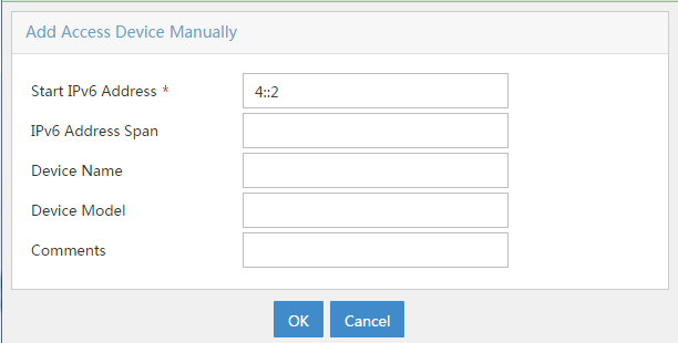
a. Add an access policy:
- Select User Access Policy > Access Policy from the navigation tree to open the access policy page.
- Click Add to open the page as shown in Figure 61.
- Enter the access policy name AccessPolicy.
- Use the default settings for other parameters.
Figure 61 Adding an access policy

a. Add an access service:
- Select User Access Policy > Access Service from the navigation tree to open the access service page.
- Click Add to open the page as shown in Figure 62.
- Enter the service name IPoE_Server.
- Select AccessPolicy from the default access policy list.
- Use the default settings for other parameters.
Figure 62 Adding an access service

a. Add a user:
- Select User Management > Add User from the navigation tree to open the adding user page, as shown in Figure 63.
- Enter the username IPoE_Web001 and the user ID 001.
- Click OK.

a. Add an access user:
- Select Access User > All Access Users from the navigation tree to open the access user page.
- Click Add to open the page as shown in Figure 64.
- Select IPoE_Web001 for the username.
- Enter the account name user1.
- Enter the password pass1.
- Select the access service IPoE_Server.
Figure 64 Adding an access user

4. Configure the portal server:
a. Configure the portal homepage:
- Select User Access Policy > Portal Service > Server from the navigation tree to open the portal server configuration page, as shown in Figure 65.
- Click OK.
Figure 65 Portal server configuration page
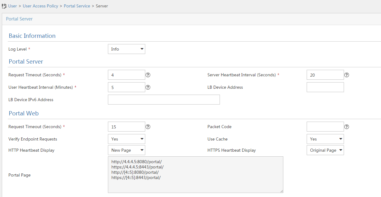
a. Configure portal authentication source IP address range:
- Select User Access Policy > Portal Service > IP Group from the navigation tree to open the portal IP address group configuration page.
- Click Add to open the page as shown in Figure 66.
- Enter the IP group name IPoE_Web_User-2.
- Select Yes from the IPv6 list.
- Enter the start IP address (192::1) and end IP address (192::FFFF) of the IP group. Make sure the host IPv6 address is in the IP group.
- Click OK.
Figure 66 Adding an IP address group (IPv6)

a. Add a portal device:
- Select User Access Policy > Portal Service > Device from the navigation tree to open the portal device configuration page.
- Click Add to open the page as shown in Figure 67.
- Enter the device name NAS-2.
- Select Portal 3.0 from the Version list.
- Enter the IP address of the portal packets' outgoing interface Ten-GigabitEthernet 3/1/1 (4::2).
- Enter the key 123456.
- Select Directly Connect for access method.
- Click OK.
Figure 67 Adding a portal device (IPv6)
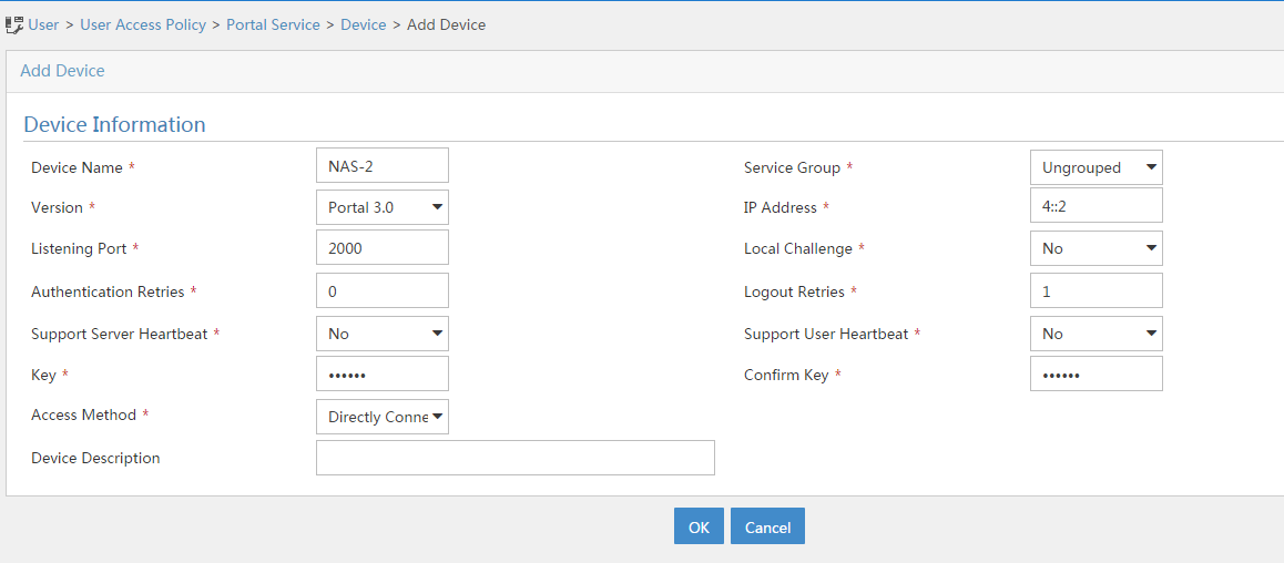
a. Associate the portal device with the IP address group:
- Click the icon in the Port Group Information Management column of device NAS to open the port group configuration page, as shown in Figure 68.
- Click Add to open the page as shown in Figure 69.
- Enter the port group name group-2.
- Select the configured IP address group IPoE_Web_User-2. Make sure the IPv6 address used by the user to access the network is within this IPv6 address group.
- Click OK.
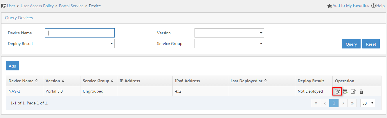
Figure 69 Port group configuration
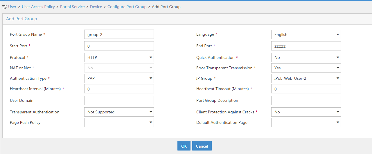
Verifying the configuration
# Display IPoE session information to verify that the host has passed preauthentication and obtained IPv6 address 192::2.
[Device] display access-user auth-type pre-auth
UserID Interface IP address MAC address S-/C-VLAN
Username IPv6 address Access type
0x33d XGE3/1/2 - 001b-21a8-0949 -/-
001b21a80949 192::2 L2 IPoE dynamic
As shown in Figure 70, the Web login page opens after preauthentication. Enter the username and password on the page.

# Display IPoE session information to verify that the host has passed Web authentication and come online.
[Device] display access-user auth-type web-auth
UserID Interface IP address MAC address S-/C-VLAN
Username IPv6 address Access type
0x33d XGE3/1/2 - 001b-21a8-0949 -/-
user1@dm2 192::2 Web auth
Example: Configuring IPoE common Web authentication for IPoE ND RS users (ND prefix pool-authorized prefix)
Network configuration
As shown in Figure 71, the host accesses the BRAS as an IPv6 ND RS user though a Layer 2 device. The BRAS can send IPv6 ND RA packets. A server installed with H3C IMC acts as the RADIUS server, the portal authentication server, and the portal Web server.

Prerequisites
Configure IP addresses for interfaces, and make sure devices can reach each other at Layer 3. (Details not shown.)
Procedure
1. Configure IP addresses and routes.
As shown in Figure 71, configure IP addresses for interfaces and make sure the BRAS and servers can reach each other at Layer 3. (Details not shown.)
2. Configure the BRAS:
a. Disable RA message suppression on Ten-GigabitEthernet 3/1/2.
<Device> system-view
[Device] interface ten-gigabitethernet 3/1/2
[Device–Ten-GigabitEthernet3/1/2] undo ipv6 nd ra halt
b. Automatically generate a link-local address for Ten-GigabitEthernet 3/1/2.
[Device–Ten-GigabitEthernet3/1/2] ipv6 address auto link-local
[Device–Ten-GigabitEthernet3/1/2] quit
c. Configure an ND prefix pool:
# Create prefix pool 1 that contains the prefix 10::/32 and specify the length of prefixes to be assigned as 64. Prefix pool 1 can assign 4294967296 prefixes in the range of 10::/64 to 10:0:FFFF:FFFF::/64.
[Device] ipv6 dhcp prefix-pool 1 prefix 10::/32 assign-len 64
# Create an IPv6 address pool named pool1, and reference prefix pool 1.
[Device] ipv6 pool pool1
[Device-ipv6-pool-pool1] prefix-pool 1 export-route
[Device-ipv6-pool-pool1] quit
d. Configure the IPv6 address of the IPv6 portal authentication server newpt2 as 4::5 and the plaintext key 123456.
[Device] portal server newpt2
[Device-portal-server-newpt2] ipv6 4::5 key simple 123456
[Device-portal-server-newpt2] quit
e. Specify 11111 as the HTTPS redirect listening port number. Make sure the port number is not used by any other service. To see the TCP port numbers used by other services, execute the display tcp command.
[Device] http-redirect https-port 11111
f. Configure the device to get user access information from ARP and ND entries.
[Device] portal access-info trust arp
[Device] portal access-info trust nd
g. Create a local user group named pre.
[Device] user-group pre
New user group added.
[Device-ugroup-pre] quit
h. Configure ACLs for preauthentication:
# Create an IPv6 advanced ACL named web_permit. Configure a rule to permit all packets destined for the portal server from users in user group pre.
[Device] acl ipv6 advanced name web_permit
[Device-acl-ipv6-adv-web_permit] rule 0 permit ipv6 destination 4::5 128 user-group pre
[Device-acl-ipv6-adv-web_permit] quit
# Create an IPv6 advanced ACL named neiwang. Configure a rule to permit all packets destined for the internal network server from users in user group pre.
[Device] acl ipv6 advanced name neiwang
[Device-acl-ipv6-adv-neiwang] rule 0 permit ipv6 destination 4::1 128 user-group pre
[Device-acl-ipv6-adv-neiwang] quit
# Create an IPv6 advanced ACL named web_http. Configure a rule to permit TCP packets with the destination port 80 (HTTP packets) from users in user group pre.
[Device] acl ipv6 advanced name web_http
[Device-acl-ipv6-adv-web_http] rule 0 permit tcp destination-port eq www user-group pre
[Device-acl-ipv6-adv-web_http] quit
# Create an IPv6 advanced ACL named web_https, and configure a rule to permit TCP packets with the destination port 443 (HTTPS packets) from users in user group pre.
[Device] acl ipv6 advanced name web_https
[Device-acl-ipv6-adv-web_https] rule 0 permit tcp destination-port eq 443 user-group pre
[Device-acl-ipv6-adv-web_https] quit
# Create an IPv6 advanced ACL named ip, and configure a rule to permit IP packets from users in user group pre.
[Device] acl ipv6 advanced name ip
[Device-acl-ipv6-adv-ip] rule 0 permit ipv6 user-group pre
[Device-acl-ipv6-adv-ip] quit
# Create an IPv6 advanced ACL named neiwang_out, and configure a rule to permit IP packets from the internal network server in user group pre.
[Device] acl ipv6 advanced name neiwang_out
[Device-acl-ipv6-adv-neiwang_out] rule 0 permit ipv6 source 4::1 128 user-group pre
[Device-acl-ipv6-adv-neiwang_out] quit
# Create an IPv6 advanced ACL named web_out, and configure a rule to permit IP packets from the portal server in user group pre.
[Device] acl ipv6 advanced name web_out
[Device-acl-ipv6-adv-web_out] rule 0 permit ipv6 source 4::5 128 user-group pre
[Device-acl-ipv6-adv-web_out] quit
i. Configure QoS traffic classes for preauthentication users:
# Create the traffic class web_permit and specify ACL web_permit as the match criterion.
[Device] traffic classifier web_permit operator or
[Device-classifier-web_permit] if-match acl ipv6 name web_permit
[Device-classifier-web_permit] quit
# Create the traffic class web_http and specify ACL web_http as the match criterion.
[Device] traffic classifier web_http operator or
[Device-classifier-web_http] if-match acl ipv6 name web_http
[Device-classifier-web_http] quit
# Create the traffic class web_https and specify ACL web_https as the match criterion.
[Device] traffic classifier web_https operator or
[Device-classifier-web_https] if-match acl ipv6 name web_https
[Device-classifier-web_https] quit
# Create the traffic class web_deny and specify ACL ip as the match criterion.
[Device] traffic classifier web_deny operator or
[Device-classifier-web_deny] if-match acl ipv6 name ip
[Device-classifier-web_deny] quit
# Create the traffic class neiwang_out and specify ACL neiwang_out as the match criterion.
[Device] traffic classifier neiwang_out operator or
[Device-classifier-neiwang_out] if-match acl ipv6 name neiwang_out
[Device-classifier-neiwang_out] quit
# Create the traffic class web_out and specify ACL web_out as the match criterion.
[Device] traffic classifier web_out operator or
[Device-classifier-web_out] if-match acl ipv6 name web_out
[Device-classifier-web_out] quit
j. Configure QoS traffic behaviors:
# Configure the traffic behavior web_permit to permit traffic to pass through without rate limiting or accounting.
[Device] traffic behavior web_permit
[Device-behavior-web_permit] filter permit
[Device-behavior-web_permit] free account
[Device-behavior-web_permit] quit
# Configure the traffic behavior neiwang to permit traffic to pass through.
[Device] traffic behavior neiwang
[Device-behavior-neiwang] filter permit
[Device-behavior-neiwang] quit
# Configure the traffic behavior web_http to redirect HTTP packets to the CPU.
[Device] traffic behavior web_http
[Device-behavior-web_http] redirect http-to-cpu
[Device-behavior-web_http] quit
# Configure the traffic behavior web_https to redirect HTTPS packets to the CPU.
[Device] traffic behavior web_https
[Device-behavior-web_https] redirect https-to-cpu
[Device-behavior-web_https] quit
# Configure the traffic behavior web_deny to deny traffic.
[Device] traffic behavior web_deny
[Device-behavior-web_deny] filter deny
[Device-behavior-web_deny] free account
[Device-behavior-web_deny] quit
# Configure the traffic behavior neiwang_out to permit traffic to pass through.
[Device] traffic behavior neiwang_out
[Device-behavior-neiwang_out] filter permit
[Device-behavior-neiwang_out] quit
# Configure the traffic behavior web_out to permit traffic without rate limiting or traffic accounting.
[Device] traffic behavior web_out
[Device-behavior-web_out] filter permit
[Device-behavior-web_out] free account
[Device-behavior-web_out] quit
k. Configure the QoS policies:
# Create a QoS policy named web.
[Device] qos policy web
# Associate the traffic class web_permit with the traffic behavior web_permit.
[Device-qospolicy-web] classifier web_permit behavior web_permit
# Associate the traffic class neiwang with the traffic behavior neiwang.
[Device-qospolicy-web] classifier neiwang behavior neiwang
# Associate the traffic class web_http with the traffic behavior web_http.
[Device-qospolicy-web] classifier web_http behavior web_http
# Associate the traffic class web_https with the traffic behavior web_https.
[Device-qospolicy-web] classifier web_https behavior web_https
# Associate the traffic class web_deny with the traffic behavior web_deny.
[Device-qospolicy-web] classifier web_deny behavior web_deny
[Device-qospolicy-web] quit
# Configure a QoS policy named out.
[Device] qos policy out
# Associate the traffic class web_out with the traffic behavior web_out. Associate the traffic class neiwang_out with the traffic behavior neiwang_out. Associate the traffic class web_deny with the traffic behavior web_deny.
[Device-qospolicy-out] classifier web_out behavior web_out
[Device-qospolicy-out] classifier neiwang_out behavior neiwang_out
[Device-qospolicy-out] classifier web_deny behavior web_deny
[Device-qospolicy-out] quit
l. Apply the QoS policies:
# Apply the QoS Policy web to the inbound traffic globally. To identify whether the QoS policy takes effect, execute the display qos policy global inbound command.
[Device] qos apply policy web global inbound
# Apply the QoS Policy out to the outbound traffic globally. To identify whether the QoS policy takes effect, execute the display qos policy global outbound command.
[Device] qos apply policy out global outbound
m. Configure a RADIUS scheme:
# Create a RADIUS scheme named rs1 and enter its view.
[Device] radius scheme rs1
# Configure primary servers and keys for authentication and accounting.
[Device-radius-rs1] primary authentication ipv6 4::5
[Device-radius-rs1] primary accounting ipv6 4::5
[Device-radius-rs1] key authentication simple radius
[Device-radius-rs1] key accounting simple radius
# Exclude the ISP name from the username sent to the RADIUS server.
[Device-radius-rs1] user-name-format without-domain
[Device-radius-rs1] quit
# (Optional.) Enable RADIUS session control. As a best practice, configure this feature when an IMC server acts as the RADIUS server.
[Device] radius session-control enable
n. Configure the preauthentication ISP domain and Web authentication ISP domain:
# Configure the ISP domain dm1 for IPoE user preauthentication.
[Device] domain name dm1
[Device-isp-dm1] authentication ipoe none
[Device-isp-dm1] authorization ipoe none
[Device-isp-dm1] accounting ipoe none
# Configure the authorized user group, ND prefix pool, and IPv6 DNS address pool in preauthentication ISP domain dm1.
[Device-isp-dm1] authorization-attribute user-group pre
[Device-isp-dm1] authorization-attribute ipv6-nd-prefix-pool pool1
[Device-isp-dm1] authorization-attribute primary-dns ipv6 8::8
# Configure the Web authentication page URL in ISP domain dm1.
[Device-isp-dm1] web-server ipv6-url http://[4::5]:8080/portal
[Device-isp-dm1] quit
# Configure the ISP domain dm2 for IPoE user Web authentication.
[Device] domain name dm2
[Device-isp-dm2] authentication ipoe radius-scheme rs1
[Device-isp-dm2] authorization ipoe radius-scheme rs1
[Device-isp-dm2] accounting ipoe radius-scheme rs1
[Device-isp-dm2] quit
o. Configure IPoE:
# Enable IPoE and configure Layer 2 access mode on Ten-GigabitEthernet 3/1/2.
[Device] interface ten-gigabitethernet 3/1/2
[Device–Ten-GigabitEthernet3/1/2] ip subscriber l2-connected enable
# Configure Web authentication for IPoE users on Ten-GigabitEthernet 3/1/2.
[Device–Ten-GigabitEthernet3/1/2] ip subscriber authentication-method web
The operation may cut all users on this interface. Continue?[Y/N]:y
# Enable IPv6 ND RS packet initiation.
[Device–Ten-GigabitEthernet3/1/2] ip subscriber initiator ndrs enable
# Configure the ISP domain dm1 for preauthentication and the ISP domain dm2 for Web authentication on Ten-GigabitEthernet 3/1/2.
[Device–Ten-GigabitEthernet3/1/2] ip subscriber pre-auth domain dm1
[Device–Ten-GigabitEthernet3/1/2] ip subscriber web-auth domain dm2
[Device–Ten-GigabitEthernet3/1/2] quit
3. Configure the RADIUS server and portal server.
For more information, see related configuration in "Example: Configuring IPoE common Web authentication for dual-stack users (URL allowlist)."
Verifying the configuration
# Display IPoE session information to verify that the host has passed preauthentication and obtained IPv6 prefix 10::/64.
[Device] display access-user auth-type pre-auth
UserID Interface IP address MAC address S-/C-VLAN
Username IPv6 address Access type
0xc XGE3/1/2 - 000c-29a6-b656 -/-
000c29a6b656 10::20C:29FF:FEA6:B6 L2 IPoE dynamic
56
As shown in Figure 72, the Web login page opens after preauthentication. Enter the username and password on the page.
# Display IPoE session information to verify that the host has passed Web authentication and come online.
[Device] display access-user auth-type web-auth
UserID Interface IP address MAC address S-/C-VLAN
Username IPv6 address Access type
0xc XGE3/1/2 - 000c-29a6-b656 -/-
user1@dm2 10::20C:29FF:FEA6:B6 Web auth
56
Example: Configuring IPoE transparent MAC-trigger authentication (Layer 2 transparent)
Network configuration
As shown in Figure 73, the host accesses the BRAS as a DHCP client though a Layer 2 device. It obtains configuration information from the DHCP server through the BRAS. A server installed with H3C IMC acts as the RADIUS server, the portal authentication server, the portal Web server, and the MAC binding server. This example uses IMC PLAT 7.1(E0303), IMC UAM 7.1(E0305), and IMC EIP 7.1(E0305). The FTP server is an internal network server.

Prerequisites
Configure IP addresses for interfaces, and make sure devices can reach each other at Layer 3. (Details not shown.)
Procedure
1. Configure the DHCP server:
# Enable DHCP.
<DHCP-server> system-view
[DHCP-server] dhcp enable
# Enable the DHCP server to return a DHCP-NAK message if the client notions of their IP addresses are incorrect.
[DHCP-server] dhcp server request-ip-address check
# Create an IP address pool named pool1 and enter its view.
[DHCP-server] ip pool pool1
# Specify primary subnet 192.168.0.0/24 for dynamic allocation in address pool pool1.
[DHCP-server-ip-pool-pool1] network 192.168.0.0 24
# Specify gateway address 192.168.0.1 in address pool pool1.
[DHCP-server-ip-pool-pool1] gateway-list 192.168.0.1
# Specify DNS server address 8.8.8.8 in address pool pool1.
[DHCP-server-ip-pool-pool1] dns-list 8.8.8.8
# Exclude IP address 192.168.0.1 from dynamic allocation in address pool pool1.
[DHCP-server-ip-pool-pool1] forbidden-ip 192.168.0.1
[DHCP-server-ip-pool-pool1] quit
# Configure the default route.
[DHCP-server] ip route-static 0.0.0.0 0 4.4.4.2
2. Configure the BRAS:
a. Configure the DHCP relay agent:
# Enable DHCP.
<Device> system-view
[Device] dhcp enable
# Enable the DHCP relay agent on Ten-GigabitEthernet 3/1/2.
[Device] interface ten-gigabitethernet 3/1/2
[Device–Ten-GigabitEthernet3/1/2] dhcp select relay
[Device–Ten-GigabitEthernet3/1/2] quit
# Create a remote BAS IP address pool named pool1.
[Device] ip pool pool1 bas remote
# Specify gateway address 192.168.0.1 in address pool pool1.
[Device-ip-pool-pool1] gateway 192.168.0.1 24
# Exclude IP address 192.168.0.1 from dynamic allocation in address pool pool1.
[Device-ip-pool-pool1] forbidden-ip 192.168.0.1
# Specify DHCP server 4.4.4.3 in address pool pool1.
[Device-ip-pool-pool1] remote-server 4.4.4.3
[Device-ip-pool-pool1] quit
b. Configure the IP address of the portal authentication server newpt as 4.4.4.5 and the plaintext key 123456.
[Device] portal server newpt
[Device-portal-server-newpt] ip 4.4.4.5 key simple 123456
[Device-portal-server-newpt] quit
c. Specify 11111 as the HTTPS redirect listening port number. Make sure the port number is not used by any other service. To see the TCP port numbers used by other services, execute the display tcp command.
[Device] http-redirect https-port 11111
d. Configure the device to get user access information from ARP and ND entries.
[Device] portal access-info trust arp
[Device] portal access-info trust nd
e. Create a local user group named pre.
[Device] user-group pre
New user group added.
[Device-ugroup-pre] quit
f. Configure ACLs for preauthentication:
# Create an IPv4 advanced ACL named web_permit. Configure a rule to permit all packets destined for the portal server from users in user group pre.
[Device] acl advanced name web_permit
[Device-acl-ipv4-adv-web_permit] rule 0 permit ip destination 4.4.4.5 0 user-group pre
[Device-acl-ipv4-adv-web_permit] quit
# Create an IPv4 advanced ACL named neiwang. Configure a rule to permit all packets destined for the internal network server from users in user group pre.
[Device] acl advanced name neiwang
[Device-acl-ipv4-adv-neiwang] rule 0 permit ip destination 4.4.4.6 0 user-group pre
[Device-acl-ipv4-adv-neiwang] quit
# Create an IPv4 advanced ACL named web_http. Configure a rule to permit TCP packets with the destination port 80 (HTTP packets) from users in user group pre.
[Device] acl advanced name web_http
[Device-acl-ipv4-adv-web_http] rule 0 permit tcp destination-port eq www user-group pre
[Device-acl-ipv4-adv-web_http] quit
# Create an IPv4 advanced ACL named web_https, and configure a rule to permit TCP packets with the destination port 443 (HTTPS packets) from users in user group pre.
[Device] acl advanced name web_https
[Device-acl-ipv4-adv-web_https] rule 0 permit tcp destination-port eq 443 user-group pre
[Device-acl-ipv4-adv-web_https] quit
# Create an IPv4 advanced ACL named ip, and configure a rule to permit IP packets from users in user group pre.
[Device] acl advanced name ip
[Device-acl-ipv4-adv-ip] rule 0 permit ip user-group pre
[Device-acl-ipv4-adv-ip] quit
# Create an IPv4 advanced ACL named neiwang_out, and configure a rule to permit IP packets from the internal network server in user group pre.
[Device] acl advanced name neiwang_out
[Device-acl-ipv4-adv-neiwang_out] rule 0 permit ip source 4.4.4.6 0 user-group pre
[Device-acl-ipv4-adv-neiwang_out] quit
# Create an IPv4 advanced ACL named web_out, and configure a rule to permit IP packets from the portal server in user group pre.
[Device] acl advanced name web_out
[Device-acl-ipv4-adv-web_out] rule 0 permit ip source 4.4.4.5 0 user-group pre
[Device-acl-ipv4-adv-web_out] quit
g. Configure QoS traffic classes for preauthentication users:
# Create the traffic class web_permit and specify ACL web_permit as the match criterion.
[Device] traffic classifier web_permit operator and
[Device-classifier-web_permit] if-match acl name web_permit
[Device-classifier-web_permit] quit
# Create the traffic class neiwang and specify ACL neiwang as the match criterion.
[Device] traffic classifier neiwang operator and
[Device-classifier-neiwang] if-match acl name neiwang
[Device-classifier-neiwang] quit
# Create the traffic class web_http and specify ACL web_http as the match criterion.
[Device] traffic classifier web_http operator and
[Device-classifier-web_http] if-match acl name web_http
[Device-classifier-web_http] quit
# Create the traffic class web_https and specify ACL web_https as the match criterion.
[Device] traffic classifier web_https operator and
[Device-classifier-web_https] if-match acl name web_https
[Device-classifier-web_https] quit
# Create the traffic class ip_cpu and specify ACL ip as the match criterion.
[Device] traffic classifier ip_cpu operator or
[Device-classifier-ip_cpu] if-match acl name ip
[Device-classifier-ip_cpu] if-match acl ipv6 name ip
[Device-classifier-ip_cpu] quit
# Create the traffic class ip_deny and specify ACL ip as the match criterion.
[Device] traffic classifier ip_deny operator or
[Device-classifier-ip_deny] if-match acl name ip
[Device-classifier-ip_deny] if-match acl ipv6 name ip
[Device-classifier-ip_deny] quit
# Create the traffic class neiwang_out and specify ACL neiwang_out as the match criterion.
[Device] traffic classifier neiwang_out operator and
[Device-classifier-neiwang_out] if-match acl name neiwang_out
[Device-classifier-neiwang_out] quit
# Create the traffic class web_out and specify ACL web_out as the match criterion.
[Device] traffic classifier web_out operator and
[Device-classifier-web_out] if-match acl name web_out
[Device-classifier-web_out] quit
h. Configure QoS traffic behaviors:
# Configure the traffic behavior web_permit to permit traffic to pass through without rate limiting or accounting.
[Device] traffic behavior web_permit
[Device-behavior-web_permit] filter permit
[Device-behavior-web_permit] free account
[Device-behavior-web_permit] quit
# Configure the traffic behavior neiwang to permit traffic to pass through.
[Device] traffic behavior neiwang
[Device-behavior-neiwang] filter permit
[Device-behavior-neiwang] quit
# Configure the traffic behavior web_http to redirect HTTP packets to the CPU.
[Device] traffic behavior web_http
[Device-behavior-web_http] redirect http-to-cpu
[Device-behavior-web_http] quit
# Configure the traffic behavior web_https to redirect HTTPS packets to the CPU.
[Device] traffic behavior web_https
[Device-behavior-web_https] redirect https-to-cpu
[Device-behavior-web_https] quit
# Configure the traffic behavior web_deny to deny traffic.
[Device] traffic behavior web_deny
[Device-behavior-web_deny] filter deny
[Device-behavior-web_deny] free account
[Device-behavior-web_deny] quit
# Configure the traffic behavior neiwang_out to permit traffic to pass through.
[Device] traffic behavior neiwang_out
[Device-behavior-neiwang_out] filter permit
[Device-behavior-neiwang_out] quit
# Configure the traffic behavior web_out to permit traffic without rate limiting or traffic accounting.
[Device] traffic behavior web_out
[Device-behavior-web_out] filter permit
[Device-behavior-web_out] free account
[Device-behavior-web_out] quit
i. Configure the QoS policies:
# Create a QoS policy named web.
[Device] qos policy web
# Associate the traffic class web_permit with the traffic behavior web_permit.
[Device-qospolicy-web] classifier web_permit behavior web_permit
# Associate the traffic class neiwang with the traffic behavior neiwang.
[Device-qospolicy-web] classifier neiwang behavior neiwang
# Associate the traffic class web_http with the traffic behavior web_http.
[Device-qospolicy-web] classifier web_http behavior web_http
# Associate the traffic class web_https with the traffic behavior web_https.
[Device-qospolicy-web] classifier web_https behavior web_https
# Associate the traffic class ip_cpu with the traffic behavior web_cpu.
[Device-qospolicy-web] classifier ip_cpu behavior web_cpu
# Associate the traffic class ip_deny with the traffic behavior web_deny.
[Device-qospolicy-web] classifier ip_deny behavior web_deny
[Device-qospolicy-web] quit
# Configure a QoS policy named out.
[Device] qos policy out
# Associate the traffic class web_out with the traffic behavior web_out. Associate the traffic class neiwang_out with the traffic behavior neiwang_out. Associate the traffic class web_deny with the traffic behavior web_deny.
[Device-qospolicy-out] classifier web_out behavior web_out
[Device-qospolicy-out] classifier neiwang_out behavior neiwang_out
[Device-qospolicy-out] classifier ip_deny behavior web_deny
[Device-qospolicy-out] quit
j. Apply the QoS policies:
# Apply the QoS Policy web to the inbound traffic globally. To identify whether the QoS policy takes effect, execute the display qos policy global inbound command.
[Device] qos apply policy web global inbound
# Apply the QoS Policy out to the outbound traffic globally. To identify whether the QoS policy takes effect, execute the display qos policy global outbound command.
[Device] qos apply policy out global outbound
k. Configure a RADIUS scheme:
# Create a RADIUS scheme named rs1 and enter its view.
[Device] radius scheme rs1
# Configure primary servers and keys for authentication and accounting.
[Device-radius-rs1] primary authentication 4.4.4.5
[Device-radius-rs1] primary accounting 4.4.4.5
[Device-radius-rs1] key authentication simple radius
[Device-radius-rs1] key accounting simple radius
# Exclude the ISP name from the username sent to the RADIUS server.
[Device-radius-rs1] user-name-format without-domain
[Device-radius-rs1] quit
# (Optional.) Enable RADIUS session control. As a best practice, configure this feature when an IMC server acts as the RADIUS server.
[Device] radius session-control enable
l. Configure the preauthentication ISP domain and Web authentication ISP domain:
# Configure the ISP domain dm1 for IPoE user preauthentication.
[Device] domain name dm1
[Device-isp-dm1] authentication ipoe none
[Device-isp-dm1] authorization ipoe none
[Device-isp-dm1] accounting ipoe none
# Configure the authorized IP address pool and user group in ISP domain dm1.
[Device-isp-dm1] authorization-attribute user-group pre
[Device-isp-dm1] authorization-attribute ip-pool pool1
# Configure the Web authentication page URL in ISP domain dm1.
[Device-isp-dm1] web-server url http://4.4.4.5:8080/portal/
[Device-isp-dm1] quit
# Configure the ISP domain dm2 for IPoE user Web authentication.
[Device] domain name dm2
[Device-isp-dm2] authentication ipoe radius-scheme rs1
[Device-isp-dm2] authorization ipoe radius-scheme rs1
[Device-isp-dm2] accounting ipoe radius-scheme rs1
[Device-isp-dm2] quit
m. Configure IPoE:
# Enable IPoE and configure Layer 2 access mode on Ten-GigabitEthernet 3/1/2.
[Device] interface ten-gigabitethernet 3/1/2
[Device–Ten-GigabitEthernet3/1/2] ip subscriber l2-connected enable
# Configure Web authentication for IPoE users on Ten-GigabitEthernet 3/1/2.
[Device–Ten-GigabitEthernet3/1/2] ip subscriber authentication-method web
The operation may cut all users on this interface. Continue?[Y/N]:y
# Configure the ISP domain dm1 for preauthentication and the ISP domain dm2 for Web authentication on Ten-GigabitEthernet 3/1/2.
[Device–Ten-GigabitEthernet3/1/2] ip subscriber pre-auth domain dm1
[Device–Ten-GigabitEthernet3/1/2] ip subscriber web-auth domain dm2
[Device–Ten-GigabitEthernet3/1/2] quit
n. Configure MAC-based quick portal authentication:
# Create MAC binding server mts.
[Device] portal mac-trigger server mts
# Specify the IP address of the MAC binding server as 4.4.4.5.
[Device-portal-mac-trigger-server-mts] ip 4.4.4.5
[Device-portal-mac-trigger-server-mts] quit
# Specify the MAC binding server mts on Ten-GigabitEthernet 3/1/2.
[Device] interface ten-gigabitethernet 3/1/2
[Device–Ten-GigabitEthernet3/1/2] portal apply mac-trigger-server mts
[Device–Ten-GigabitEthernet3/1/2] quit
3. Configure the RADIUS server:
a. Configure the access device:
- Log in to the IMC platform and click the User tab.
- Select User Access Policy > Access Device Management > Access Device from the navigation tree to open the access device configuration page.
- Click Add to open the page as shown in Figure 74.
- Enter the shared key radius.
- Use the default settings for other parameters.
Figure 74 Adding an access device

- Click Add Manually in the Device List area to open the page as shown in Figure 75.
- Enter the access device's IP address 4.4.4.2.
- Click OK.
Figure 75 Manually adding an access device

a. Add an access policy:
- Select User Access Policy > Access Policy from the navigation tree to open the access policy page.
- Click Add to open the page as shown in Figure 76.
- Enter the access policy name AccessPolicy.
- Use the default settings for other parameters.
Figure 76 Adding an access policy

a. Add an access service:
- Select User Access Policy > Access Service from the navigation tree to open the access service page.
- Click Add to open the page as shown in Figure 77.
- Enter the service name IPoE_Server.
- Select AccessPolicy from the default access policy list.
- Use the default settings for other parameters.
Figure 77 Adding an access service

a. Add a user:
- Select User Management > Add User from the navigation tree to open the adding user page, as shown in Figure 78.
- Enter the username IPoE_Web001 and the user ID 001.
- Click OK.

a. Add an access user:
- Select Access User > All Access Users from the navigation tree to open the access user page
- Click Add to open the page as shown in Figure 79.
- Select IPoE_Web001 for the username.
- Enter the account name user1.
- Enter the password pass1.
- Select the access service IPoE_Server.
Figure 79 Adding an access user
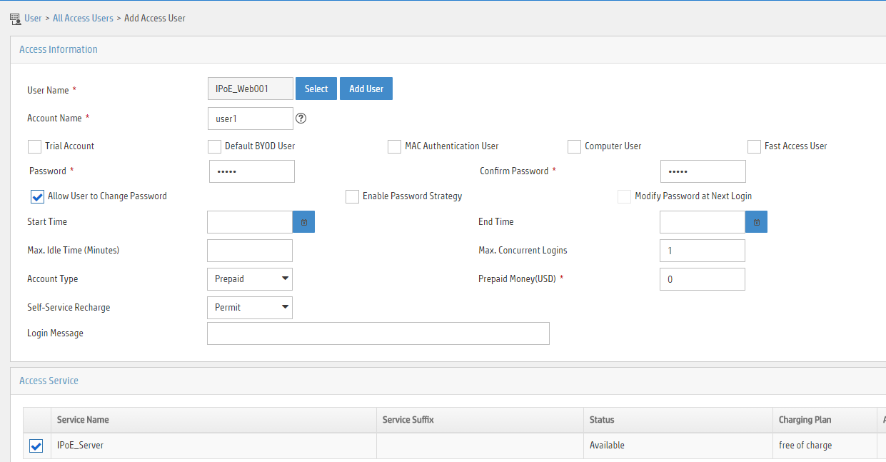
4. Configure the portal server:
a. Configure the portal homepage:
- Select User Access Policy > Portal Service > Server from the navigation tree to open the portal server configuration page, as shown in Figure 80.
- Click OK.
Figure 80 Portal server configuration page

a. Configure portal authentication source IP address range:
- Select User Access Policy > Portal Service > IP Group from the navigation tree to open the portal IP address group configuration page.
- Click Add to open the page as shown in Figure 81.
- Enter the IP group name IPoE_Web_User.
- Enter the start IP address (192.168.0.1) and end IP address (192.168.0.255) of the IP group. Make sure the host IP address is in the IP group.
- Click OK.
Figure 81 Adding an IP address group
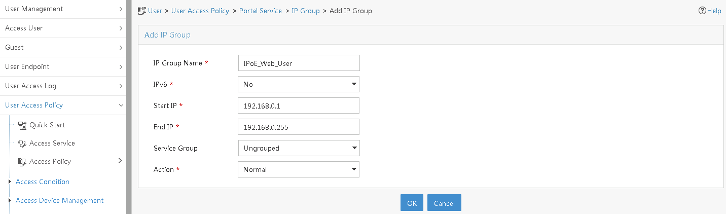
a. Add a portal device:
- Select User Access Policy > Portal Service > Device from the navigation tree to open the portal device configuration page.
- Click Add to open the page as shown in Figure 82.
- Enter the device name NAS.
- Enter the IP address of the portal packets' outgoing interface Ten-GigabitEthernet 3/1/1 (4.4.4.2).
- Enter the key 123456
- Select Directly Connect for access method.
- Click OK.
Figure 82 Adding a portal device

a. Associate the portal device with the IP address group:
- Click the icon in the Port Group Information Management column of device NAS to open the port group configuration page, as shown in Figure 83.
- Click Add to open the page as shown in Figure 84.
- Enter the port group name group.
- Select the configured IP address group IPoE_Web_User. Make sure the IP address used by the user to access the network is within this IP address group.
- Select Supported in the Transparent Authentication list.
- Click OK.

Figure 84 Port group configuration

a. From the navigation tree, select User Access Manager > Service Parameters > Validate System Configuration to validate the settings.
Verifying the configuration
# Display IPoE session information to verify that the host has passed preauthentication.
[Device] display access-user auth-type pre-auth
UserID Interface IP address MAC address S-/C-VLAN
Username IPv6 address Access type
0x33d XGE3/1/2 192.168.0.2 0015-e947-f4d4 -/-
0015e947f4d4 - L2 IPoE dynamic
As shown in Figure 85, the Web login page opens after preauthentication. Enter the username and password on the page.
# Display IPoE session information to verify that the host has passed Web authentication and come online.
[Device] display access-user auth-type web-auth
UserID Interface IP address MAC address S-/C-VLAN
Username IPv6 address Access type
0x33d XGE3/1/2 192.168.0.2 0015-e947-f4d4 -/-
user1@dm2 - Web auth
# Click Log Out on the Web login page as shown in Figure 85.
# Verify that the user returns to the preauthentication status.
[Device] display access-user auth-type pre-auth
UserID Interface IP address MAC address S-/C-VLAN
Username IPv6 address Access type
0x33d XGE3/1/2 192.168.0.2 0015-e947-f4d4 -/-
0015e947f4d4 - L2 IPoE dynamic
# Open the browser, and enter an address randomly, for example, http://63.1.1.240.
# Verify that the user has come online through IPoE Web authentication.
[Device] display access-user auth-type web-auth
UserID Interface IP address MAC address S-/C-VLAN
Username IPv6 address Access type
0x33d XGE3/1/2 192.168.0.2 0015-e947-f4d4 -/-
0015e947f4d4 - Web auth
Example: Configuring IPoE common transparent MAC authentication (Layer 2 transparent)
Network configuration
As shown in Figure 86, the host accesses the BRAS as a DHCP client though a Layer 2 device. It obtains configuration information from the DHCP server through the BRAS. The BRAS performs AAA for the host through the RADIUS server. A server installed with H3C IMC acts as the portal authentication server and the portal Web server. This example uses IMC PLAT 7.1(E0303), IMC UAM 7.1(E0305), and IMC EIP 7.1(E0305). The RADIUS server supports MAC binding, acts as the authentication, authorization, and accounting server, and performs MAC binding. The FTP server is an internal network server.

Prerequisites
Configure IP addresses for interfaces, and make sure devices can reach each other at Layer 3. (Details not shown.)
Procedure
1. Configure the DHCP server:
# Enable DHCP.
<DHCP-server> system-view
[DHCP-server] dhcp enable
# Enable the DHCP server to return a DHCP-NAK message if the client notions of their IP addresses are incorrect.
[DHCP-server] dhcp server request-ip-address check
# Create an IP address pool named pool1 and enter its view.
[DHCP-server] ip pool pool1
# Specify primary subnet 192.168.0.0/24 for dynamic allocation in address pool pool1.
[DHCP-server-ip-pool-pool1] network 192.168.0.0 24
# Specify gateway address 192.168.0.1 in address pool pool1.
[DHCP-server-ip-pool-pool1] gateway-list 192.168.0.1
# Specify DNS server address 8.8.8.8 in address pool pool1.
[DHCP-server-ip-pool-pool1] dns-list 8.8.8.8
# Exclude IP address 192.168.0.1 from dynamic allocation in address pool pool1.
[DHCP-server-ip-pool-pool1] forbidden-ip 192.168.0.1
[DHCP-server-ip-pool-pool1] quit
# Configure the default route.
[DHCP-server] ip route-static 0.0.0.0 0 4.4.4.2
2. Configure the BRAS:
a. Configure the DHCP relay agent:
# Enable DHCP.
<Device> system-view
[Device] dhcp enable
# Enable the DHCP relay agent on Ten-GigabitEthernet 3/1/2.
[Device] interface ten-gigabitethernet 3/1/2
[Device–Ten-GigabitEthernet3/1/2] dhcp select relay
[Device–Ten-GigabitEthernet3/1/2] quit
# Create a remote BAS IP address pool named pool1 for the DHCP relay agent.
[Device] ip pool pool1 bas remote
# Specify gateway address 192.168.0.1 in address pool pool1.
[Device-ip-pool-pool1] gateway 192.168.0.1 24
# Exclude IP address 192.168.0.1 from dynamic allocation in address pool pool1.
[Device-ip-pool-pool1] forbidden-ip 192.168.0.1
# Specify DHCP server 4.4.4.3 in address pool pool1.
[Device-ip-pool-pool1] remote-server 4.4.4.3
[Device-ip-pool-pool1] quit
b. Configure the IP address of the portal authentication server newpt as 4.4.4.5 and the plaintext key 123456.
[Device] portal server newpt
[Device-portal-server-newpt] ip 4.4.4.5 key simple 123456
[Device-portal-server-newpt] quit
c. Specify 11111 as the HTTPS redirect listening port number. Make sure the port number is not used by any other service. To see the TCP port numbers used by other services, execute the display tcp command.
[Device] http-redirect https-port 11111
d. Configure the device to get user access information from ARP and ND entries.
[Device] portal access-info trust arp
[Device] portal access-info trust nd
e. Create a local user group named pre.
[Device] user-group pre
New user group added.
[Device-ugroup-pre] quit
f. Configure ACLs for preauthentication:
# Create an IPv4 advanced ACL named web_permit. Configure a rule to permit all packets destined for the portal server from users in user group pre.
[Device] acl advanced name web_permit
[Device-acl-ipv4-adv-web_permit] rule 0 permit ip destination 4.4.4.5 0 user-group pre
[Device-acl-ipv4-adv-web_permit] quit
# Create an IPv4 advanced ACL named neiwang. Configure a rule to permit all packets destined for the internal network server from users in user group pre.
[Device] acl advanced name neiwang
[Device-acl-ipv4-adv-neiwang] rule 0 permit ip destination 4.4.4.6 0 user-group pre
[Device-acl-ipv4-adv-neiwang] quit
# Create an IPv4 advanced ACL named web_http. Configure a rule to permit TCP packets with the destination port 80 (HTTP packets) from users in user group pre.
[Device] acl advanced name web_http
[Device-acl-ipv4-adv-web_http] rule 0 permit tcp destination-port eq www user-group pre
[Device-acl-ipv4-adv-web_http] quit
# Create an IPv4 advanced ACL named web_https, and configure a rule to permit TCP packets with the destination port 443 (HTTPS packets) from users in user group pre.
[Device] acl advanced name web_https
[Device-acl-ipv4-adv-web_https] rule 0 permit tcp destination-port eq 443 user-group pre
[Device-acl-ipv4-adv-web_https] quit
# Create an IPv4 advanced ACL named ip, and configure a rule to permit IP packets from users in user group pre.
[Device] acl advanced name ip
[Device-acl-ipv4-adv-ip] rule 0 permit ip user-group pre
[Device-acl-ipv4-adv-ip] quit
# Create an IPv4 advanced ACL named neiwang_out, and configure a rule to permit IP packets from the internal network server in user group pre.
[Device] acl advanced name neiwang_out
[Device-acl-ipv4-adv-neiwang_out] rule 0 permit ip source 4.4.4.6 0 user-group pre
[Device-acl-ipv4-adv-neiwang_out] quit
# Create an IPv4 advanced ACL named web_out, and configure a rule to permit IP packets from the portal server in user group pre.
[Device] acl advanced name web_out
[Device-acl-ipv4-adv-web_out] rule 0 permit ip source 4.4.4.5 0 user-group pre
[Device-acl-ipv4-adv-web_out] quit
g. Configure QoS traffic classes for preauthentication users:
# Create the traffic class web_permit and specify ACL web_permit as the match criterion.
[Device] traffic classifier web_permit operator and
[Device-classifier-web_permit] if-match acl name web_permit
[Device-classifier-web_permit] quit
# Create the traffic class neiwang and specify ACL neiwang as the match criterion.
[Device] traffic classifier neiwang operator and
[Device-classifier-neiwang] if-match acl name neiwang
[Device-classifier-neiwang] quit
# Create the traffic class web_http and specify ACL web_http as the match criterion.
[Device] traffic classifier web_http operator and
[Device-classifier-web_http] if-match acl name web_http
[Device-classifier-web_http] quit
# Create the traffic class web_https and specify ACL web_https as the match criterion.
[Device] traffic classifier web_https operator and
[Device-classifier-web_https] if-match acl name web_https
[Device-classifier-web_https] quit
# Create the traffic class ip_cpu and specify ACL ip as the match criterion.
[Device] traffic classifier ip_cpu operator or
[Device-classifier-ip_cpu] if-match acl name ip
[Device-classifier-ip_cpu] if-match acl ipv6 name ip
[Device-classifier-ip_cpu] quit
# Create the traffic class ip_deny and specify ACL ip as the match criterion.
[Device] traffic classifier ip_deny operator or
[Device-classifier-ip_deny] if-match acl name ip
[Device-classifier-ip_deny] if-match acl ipv6 name ip
[Device-classifier-ip_deny] quit
# Create the traffic class neiwang_out and specify ACL neiwang_out as the match criterion.
[Device] traffic classifier neiwang_out operator and
[Device-classifier-neiwang_out] if-match acl name neiwang_out
[Device-classifier-neiwang_out] quit
# Create the traffic class web_out and specify ACL web_out as the match criterion.
[Device] traffic classifier web_out operator and
[Device-classifier-web_out] if-match acl name web_out
[Device-classifier-web_out] quit
h. Configure QoS traffic behaviors:
# Configure the traffic behavior web_permit to permit traffic to pass through without rate limiting or accounting.
[Device] traffic behavior web_permit
[Device-behavior-web_permit] filter permit
[Device-behavior-web_permit] free account
[Device-behavior-web_permit] quit
# Configure the traffic behavior neiwang to permit traffic to pass through.
[Device] traffic behavior neiwang
[Device-behavior-neiwang] filter permit
[Device-behavior-neiwang] quit
# Configure the traffic behavior web_http to redirect HTTP packets to the CPU.
[Device] traffic behavior web_http
[Device-behavior-web_http] redirect http-to-cpu
[Device-behavior-web_http] quit
# Configure the traffic behavior web_https to redirect HTTPS packets to the CPU.
[Device] traffic behavior web_https
[Device-behavior-web_https] redirect https-to-cpu
[Device-behavior-web_https] quit
# Configure the traffic behavior web_deny to deny traffic.
[Device] traffic behavior web_deny
[Device-behavior-web_deny] filter deny
[Device-behavior-web_deny] free account
[Device-behavior-web_deny] quit
# Configure the traffic behavior neiwang_out to permit traffic to pass through.
[Device] traffic behavior neiwang_out
[Device-behavior-neiwang_out] filter permit
[Device-behavior-neiwang_out] quit
# Configure the traffic behavior web_out to permit traffic without rate limiting or traffic accounting.
[Device] traffic behavior web_out
[Device-behavior-web_out] filter permit
[Device-behavior-web_out] free account
[Device-behavior-web_out] quit
i. Configure the QoS policies:
# Create a QoS policy named web.
[Device] qos policy web
# Associate the traffic class web_permit with the traffic behavior web_permit.
[Device-qospolicy-web] classifier web_permit behavior web_permit
# Associate the traffic class neiwang with the traffic behavior neiwang.
[Device-qospolicy-web] classifier neiwang behavior neiwang
# Associate the traffic class web_http with the traffic behavior web_http.
[Device-qospolicy-web] classifier web_http behavior web_http
# Associate the traffic class web_https with the traffic behavior web_https.
[Device-qospolicy-web] classifier web_https behavior web_https
# Associate the traffic class ip_cpu with the traffic behavior web_cpu.
[Device-qospolicy-web] classifier ip_cpu behavior web_cpu
# Associate the traffic class ip_deny with the traffic behavior web_deny.
[Device-qospolicy-web] classifier ip_deny behavior web_deny
[Device-qospolicy-web] quit
# Configure a QoS policy named out.
[Device] qos policy out
# Associate the traffic class web_out with the traffic behavior web_out. Associate the traffic class neiwang_out with the traffic behavior neiwang_out. Associate the traffic class web_deny with the traffic behavior web_deny.
[Device-qospolicy-out] classifier web_out behavior web_out
[Device-qospolicy-out] classifier neiwang_out behavior neiwang_out
[Device-qospolicy-out] classifier ip_deny behavior web_deny
[Device-qospolicy-out] quit
j. Apply the QoS policies:
# Apply the QoS Policy web to the inbound traffic globally. To identify whether the QoS policy takes effect, execute the display qos policy global inbound command.
[Device] qos apply policy web global inbound
# Apply the QoS Policy out to the outbound traffic globally. To identify whether the QoS policy takes effect, execute the display qos policy global outbound command.
[Device] qos apply policy out global outbound
k. Configure a RADIUS scheme:
# Create a RADIUS scheme named rs1 and enter its view.
[Device] radius scheme rs1
# Configure primary servers and keys for authentication and accounting.
[Device-radius-rs1] primary authentication 4.4.4.1
[Device-radius-rs1] primary accounting 4.4.4.1
[Device-radius-rs1] key authentication simple radius
[Device-radius-rs1] key accounting simple radius
# Exclude the ISP name from the username sent to the RADIUS server.
[Device-radius-rs1] user-name-format without-domain
[Device-radius-rs1] quit
# (Optional.) Enable RADIUS session control. As a best practice, configure this feature when an IMC server acts as the RADIUS server.
[Device] radius session-control enable
l. Configure the preauthentication ISP domain and Web authentication ISP domain:
# Configure the ISP domain dm1 for IPoE user preauthentication.
[Device] domain name dm1
[Device-isp-dm1] authentication ipoe none
[Device-isp-dm1] authorization ipoe none
[Device-isp-dm1] accounting ipoe none
# Configure the authorized IP address pool and user group in ISP domain dm1.
[Device-isp-dm1] authorization-attribute user-group pre
[Device-isp-dm1] authorization-attribute ip-pool pool1
# Configure the Web authentication page URL in ISP domain dm1.
[Device-isp-dm1] web-server url http://4.4.4.5:8080/portal/
[Device-isp-dm1] quit
# Configure the ISP domain dm2 for IPoE user Web authentication.
[Device] domain name dm2
[Device-isp-dm2] authentication ipoe radius-scheme rs1
[Device-isp-dm2] authorization ipoe radius-scheme rs1
[Device-isp-dm2] accounting ipoe radius-scheme rs1
[Device-isp-dm2] quit
m. Configure IPoE:
# Enable IPoE and configure Layer 2 access mode on Ten-GigabitEthernet 3/1/2.
[Device] interface ten-gigabitethernet 3/1/2
[Device–Ten-GigabitEthernet3/1/2] ip subscriber l2-connected enable
# Configure Web MAC authentication for IPoE users on Ten-GigabitEthernet 3/1/2.
[Device–Ten-GigabitEthernet3/1/2] ip subscriber authentication-method web mac-auth
The operation may cut all users on this interface. Continue?[Y/N]:y
# Configure the ISP domain dm1 for preauthentication and the ISP domain dm2 for Web authentication on Ten-GigabitEthernet 3/1/2.
[Device–Ten-GigabitEthernet3/1/2] ip subscriber pre-auth domain dm1
[Device–Ten-GigabitEthernet3/1/2] ip subscriber web-auth domain dm2
[Device–Ten-GigabitEthernet3/1/2] quit
3. Configure the RADIUS server.
For more information about configuring AAA and MAC binding on the RADIUS server, see the configuration guide for the RADIUS server.
4. Configure the portal server:
a. Configure the portal homepage:
- Select User Access Policy > Portal Service > Server from the navigation tree to open the portal server configuration page, as shown in Figure 87.
- Click OK.
Figure 87 Portal server configuration page

a. Configure portal authentication source IP address range:
- Select User Access Policy > Portal Service > IP Group from the navigation tree to open the portal IP address group configuration page.
- Click Add to open the page as shown in Figure 88.
- Enter the IP group name IPoE_Web_User.
- Enter the start IP address (192.168.0.1) and end IP address (192.168.0.255) of the IP group. Make sure the host IP address is in the IP group.
- Click OK.
Figure 88 Adding an IP address group

a. Add a portal device:
- Select User Access Policy > Portal Service > Device from the navigation tree to open the portal device configuration page.
- Click Add to open the page as shown in Figure 89.
- Enter the device name NAS.
- Enter the IP address of the portal packets' outgoing interface Ten-GigabitEthernet 3/1/1 (4.4.4.2).
- Enter the key 123456.
- Select Directly Connect for access method.
- Click OK.
Figure 89 Adding a portal device

a. Associate the portal device with the IP address group:
- Click the icon in the Port Group Information Management column of device NAS to open the port group configuration page, as shown in Figure 90.
- Click Add to open the page as shown in Figure 91.
- Enter the port group name group.
- Select the configured IP address group IPoE_Web_User. Make sure the IP address used by the user to access the network is within this IP address group.
- Click OK.

Figure 91 Port group configuration

Verifying the configuration
# Display IPoE session information to verify that the host has passed preauthentication.
[Device] display access-user auth-type pre-auth
UserID Interface IP address MAC address S-/C-VLAN
Username IPv6 address Access type
0x33d XGE3/1/2 192.168.0.2 0015-e947-f4d4 -/-
0015e947f4d4 - L2 IPoE dynamic
As shown in Figure 92, the Web login page opens after preauthentication. Enter the username and password on the page.
# Display IPoE session information to verify that the host has passed Web authentication and come online.
[Device] display access-user auth-type web-auth
UserID Interface IP address MAC address S-/C-VLAN
Username IPv6 address Access type
0x33d XGE3/1/2 192.168.0.2 0015-e947-f4d4 -/-
user1@dm2 - Web auth
# Click Log Out on the page as shown in Figure 92.
# Verify that the user returns to the preauthentication status.
[Device] display access-user auth-type pre-auth
UserID Interface IP address MAC address S-/C-VLAN
Username IPv6 address Access type
0x33d XGE3/1/2 192.168.0.2 0015-e947-f4d4 -/-
0015e947f4d4 - L2 IPoE dynamic
# Open the browser, and enter any address in the address bar to access http://63.1.1.240/. Display session information. The output shows that the user has come online through Web authentication.
[Device] display access-user auth-type web-auth
UserID Interface IP address MAC address S-/C-VLAN
Username IPv6 address Access type
0x33d XGE3/1/2 192.168.0.2 0015-e947-f4d4 -/-
0015e947f4d4 - Web auth
Example: Configuring IPoE re-DHCP transparent MAC authentication (Layer 2 transparent)
Network configuration
As shown in Figure 93:
· The host accesses the BRAS as a DHCP client though a Layer 2 device.
· The host obtains configuration information from the DHCP server through the BRAS. Before the user passes transparent MAC authentication, the user is assigned an IP address on network segment 192.168.0.0/24. After the user passes transparent MAC authentication, the user is assigned an IP address on network segment 123.1.1.0/24.
· A server installed with H3C IMC acts as the portal authentication server and the portal Web server. This example uses IMC PLAT 7.1(E0303), IMC UAM 7.1(E0305), and IMC EIP 7.1(E0305).
· The RADIUS server supports MAC binding, acts as the authentication, authorization, and accounting server, and performs MAC binding. The FTP server is an internal network server.
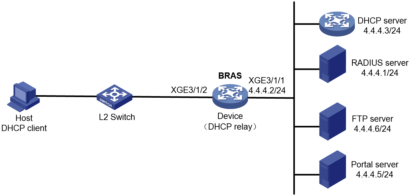
Prerequisites
Configure IP addresses for interfaces, and make sure devices can reach each other at Layer 3. (Details not shown.)
Procedure
1. Configure the DHCP server:
# Enable DHCP.
<DHCP-server> system-view
[DHCP-server] dhcp enable
# Enable the DHCP server to return a DHCP-NAK message if the client notions of their IP addresses are incorrect.
[DHCP-server] dhcp server request-ip-address check
# Create an IP address pool named pool1 and enter its view.
[DHCP-server] ip pool pool1
# Specify primary subnet 192.168.0.0/24 for dynamic allocation in address pool pool1.
[DHCP-server-ip-pool-pool1] network 192.168.0.0 24
# Specify gateway address 192.168.0.1 in address pool pool1.
[DHCP-server-ip-pool-pool1] gateway-list 192.168.0.1
# Specify DNS server address 8.8.8.8 in address pool pool1.
[DHCP-server-ip-pool-pool1] dns-list 8.8.8.8
# Exclude IP address 192.168.0.1 from dynamic allocation in address pool pool1.
[DHCP-server-ip-pool-pool1] forbidden-ip 192.168.0.1
[DHCP-server-ip-pool-pool1] quit
# Create an IP address pool named pool2 and enter its view.
[DHCP-server] ip pool pool2
# Specify primary subnet 123.1.1.0/24 for dynamic allocation in address pool pool2.
[DHCP-server-ip-pool-pool2] network 123.1.1.0 24
# Specify gateway address 123.1.1.1 in address pool pool2.
[DHCP-server-ip-pool-pool2] gateway-list 123.1.1.1
# Specify DNS server address 8.8.8.8 in address pool pool2.
[DHCP-server-ip-pool-pool2] dns-list 8.8.8.8
# Exclude IP address 123.1.1.1 from dynamic allocation in address pool pool1.
[DHCP-server-ip-pool-pool2] forbidden-ip 123.1.1.1
[DHCP-server-ip-pool-pool2] quit
# Configure the default route.
[DHCP-server] ip route-static 0.0.0.0 0 4.4.4.2
2. Configure the BRAS:
a. Configure the DHCP relay agent:
# Enable DHCP.
<Device> system-view
[Device] dhcp enable
# Enable the DHCP relay agent on Ten-GigabitEthernet 3/1/2.
[Device] interface ten-gigabitethernet 3/1/2
[Device–Ten-GigabitEthernet3/1/2] dhcp select relay
[Device–Ten-GigabitEthernet3/1/2] quit
# Create a remote BAS IP address pool named pool1 for the DHCP relay agent.
[Device] ip pool pool1 bas remote
# Specify gateway address 192.168.0.1/24 in address pool pool1.
[Device-ip-pool-pool1] gateway 192.168.0.1 24
# Exclude IP address 192.168.0.1 from dynamic allocation in address pool pool1.
[Device-ip-pool-pool1] forbidden-ip 192.168.0.1
# Specify DHCP server 4.4.4.3 in address pool pool1.
[Device-ip-pool-pool1] remote-server 4.4.4.3
[Device-ip-pool-pool1] quit
# Create a remote BAS IP address pool named pool2 for the DHCP relay agent.
[Device] ip pool pool2 bas remote
# Specify gateway address 123.1.1.1/24 in address pool pool2.
[Device-ip-pool-pool2] gateway 123.1.1.1 24
# Exclude IP address 123.1.1.1 from dynamic allocation in address pool pool2.
[Device-ip-pool-pool2] forbidden-ip 123.1.1.1
# Specify DHCP server 4.4.4.3 in address pool pool2.
[Device-ip-pool-pool2] remote-server 4.4.4.3
[Device-ip-pool-pool2] quit
b. Configure the IP address of the portal authentication server newpt as 4.4.4.5 and the plaintext key 123456.
[Device] portal server newpt
[Device-portal-server-newpt] ip 4.4.4.5 key simple 123456
[Device-portal-server-newpt] quit
c. Specify 11111 as the HTTPS redirect listening port number. Make sure the port number is not used by any other service. To see the TCP port numbers used by other services, execute the display tcp command.
[Device] http-redirect https-port 11111
d. Configure the device to get user access information from ARP and ND entries.
[Device] portal access-info trust arp
[Device] portal access-info trust nd
e. Create a local user group named pre.
[Device] user-group pre
New user group added.
[Device-ugroup-pre] quit
f. Configure ACLs for preauthentication:
# Create an IPv4 advanced ACL named web_permit. Configure a rule to permit all packets destined for the portal server from users in user group pre.
[Device] acl advanced name web_permit
[Device-acl-ipv4-adv-web_permit] rule 0 permit ip destination 4.4.4.5 0 user-group pre
[Device-acl-ipv4-adv-web_permit] quit
# Create an IPv4 advanced ACL named neiwang. Configure a rule to permit all packets destined for the internal network server from users in user group pre.
[Device] acl advanced name neiwang
[Device-acl-ipv4-adv-neiwang] rule 0 permit ip destination 4.4.4.6 0 user-group pre
[Device-acl-ipv4-adv-neiwang] quit
# Create an IPv4 advanced ACL named web_http. Configure a rule to permit TCP packets with the destination port 80 (HTTP packets) from users in user group pre.
[Device] acl advanced name web_http
[Device-acl-ipv4-adv-web_http] rule 0 permit tcp destination-port eq www user-group pre
[Device-acl-ipv4-adv-web_http] quit
# Create an IPv4 advanced ACL named web_https, and configure a rule to permit TCP packets with the destination port 443 (HTTPS packets) from users in user group pre.
[Device] acl advanced name web_https
[Device-acl-ipv4-adv-web_https] rule 0 permit tcp destination-port eq 443 user-group pre
[Device-acl-ipv4-adv-web_https] quit
# Create an IPv4 advanced ACL named ip, and configure a rule to permit IP packets from users in user group pre.
[Device] acl advanced name ip
[Device-acl-ipv4-adv-ip] rule 0 permit ip user-group pre
[Device-acl-ipv4-adv-ip] quit
# Create an IPv4 advanced ACL named neiwang_out, and configure a rule to permit IP packets from the internal network server in user group pre.
[Device] acl advanced name neiwang_out
[Device-acl-ipv4-adv-neiwang_out] rule 0 permit ip source 4.4.4.6 0 user-group pre
[Device-acl-ipv4-adv-neiwang_out] quit
# Create an IPv4 advanced ACL named web_out, and configure a rule to permit IP packets from the portal server in user group pre.
[Device] acl advanced name web_out
[Device-acl-ipv4-adv-web_out] rule 0 permit ip source 4.4.4.5 0 user-group pre
[Device-acl-ipv4-adv-web_out] quit
g. Configure QoS traffic classes for preauthentication users:
# Create the traffic class web_permit and specify ACL web_permit as the match criterion.
[Device] traffic classifier web_permit operator and
[Device-classifier-web_permit] if-match acl name web_permit
[Device-classifier-web_permit] quit
# Create the traffic class neiwang and specify ACL neiwang as the match criterion.
[Device] traffic classifier neiwang operator and
[Device-classifier-neiwang] if-match acl name neiwang
[Device-classifier-neiwang] quit
# Create the traffic class web_http and specify ACL web_http as the match criterion.
[Device] traffic classifier web_http operator and
[Device-classifier-web_http] if-match acl name web_http
[Device-classifier-web_http] quit
# Create the traffic class web_https and specify ACL web_https as the match criterion.
[Device] traffic classifier web_https operator and
[Device-classifier-web_https] if-match acl name web_https
[Device-classifier-web_https] quit
# Create the traffic class ip_cpu and specify ACL ip as the match criterion.
[Device] traffic classifier ip_cpu operator or
[Device-classifier-ip_cpu] if-match acl name ip
[Device-classifier-ip_cpu] if-match acl ipv6 name ip
[Device-classifier-ip_cpu] quit
# Create the traffic class ip_deny and specify ACL ip as the match criterion.
[Device] traffic classifier ip_deny operator or
[Device-classifier-ip_deny] if-match acl name ip
[Device-classifier-ip_deny] if-match acl ipv6 name ip
[Device-classifier-ip_deny] quit
# Create the traffic class neiwang_out and specify ACL neiwang_out as the match criterion.
[Device] traffic classifier neiwang_out operator and
[Device-classifier-neiwang_out] if-match acl name neiwang_out
[Device-classifier-neiwang_out] quit
# Create the traffic class web_out and specify ACL web_out as the match criterion.
[Device] traffic classifier web_out operator and
[Device-classifier-web_out] if-match acl name web_out
[Device-classifier-web_out] quit
h. Configure QoS traffic behaviors:
# Configure the traffic behavior web_permit to permit traffic to pass through without rate limiting or accounting.
[Device] traffic behavior web_permit
[Device-behavior-web_permit] filter permit
[Device-behavior-web_permit] free account
[Device-behavior-web_permit] quit
# Configure the traffic behavior neiwang to permit traffic to pass through.
[Device] traffic behavior neiwang
[Device-behavior-neiwang] filter permit
[Device-behavior-neiwang] quit
# Configure the traffic behavior web_http to redirect HTTP packets to the CPU.
[Device] traffic behavior web_http
[Device-behavior-web_http] redirect http-to-cpu
[Device-behavior-web_http] quit
# Configure the traffic behavior web_https to redirect HTTPS packets to the CPU.
[Device] traffic behavior web_https
[Device-behavior-web_https] redirect https-to-cpu
[Device-behavior-web_https] quit
# Configure the traffic behavior web_deny to deny traffic.
[Device] traffic behavior web_deny
[Device-behavior-web_deny] filter deny
[Device-behavior-web_deny] free account
[Device-behavior-web_deny] quit
# Configure the traffic behavior neiwang_out to permit traffic to pass through.
[Device] traffic behavior neiwang_out
[Device-behavior-neiwang_out] filter permit
[Device-behavior-neiwang_out] quit
# Configure the traffic behavior web_out to permit traffic without rate limiting or traffic accounting.
[Device] traffic behavior web_out
[Device-behavior-web_out] filter permit
[Device-behavior-web_out] free account
[Device-behavior-web_out] quit
i. Configure the QoS policies:
# Create a QoS policy named web.
[Device] qos policy web
# Associate the traffic class web_permit with the traffic behavior web_permit.
[Device-qospolicy-web] classifier web_permit behavior web_permit
# Associate the traffic class neiwang with the traffic behavior neiwang.
[Device-qospolicy-web] classifier neiwang behavior neiwang
# Associate the traffic class web_http with the traffic behavior web_http.
[Device-qospolicy-web] classifier web_http behavior web_http
# Associate the traffic class web_https with the traffic behavior web_https.
[Device-qospolicy-web] classifier web_https behavior web_https
# Associate the traffic class ip_cpu with the traffic behavior web_cpu.
[Device-qospolicy-web] classifier ip_cpu behavior web_cpu
# Associate the traffic class ip_deny with the traffic behavior web_deny.
[Device-qospolicy-web] classifier ip_deny behavior web_deny
[Device-qospolicy-web] quit
# Configure a QoS policy named out.
[Device] qos policy out
# Associate the traffic class web_out with the traffic behavior web_out. Associate the traffic class neiwang_out with the traffic behavior neiwang_out. Associate the traffic class web_deny with the traffic behavior web_deny.
[Device-qospolicy-out] classifier web_out behavior web_out
[Device-qospolicy-out] classifier neiwang_out behavior neiwang_out
[Device-qospolicy-out] classifier ip_deny behavior web_deny
[Device-qospolicy-out] quit
j. Apply the QoS policies:
# Apply the QoS Policy web to the inbound traffic globally. To identify whether the QoS policy takes effect, execute the display qos policy global inbound command.
[Device] qos apply policy web global inbound
# Apply the QoS Policy out to the outbound traffic globally. To identify whether the QoS policy takes effect, execute the display qos policy global outbound command.
[Device] qos apply policy out global outbound
k. Configure a RADIUS scheme:
# Create a RADIUS scheme named rs1 and enter its view.
[Device] radius scheme rs1
# Configure primary servers and keys for authentication and accounting.
[Device-radius-rs1] primary authentication 4.4.4.1
[Device-radius-rs1] primary accounting 4.4.4.1
[Device-radius-rs1] key authentication simple radius
[Device-radius-rs1] key accounting simple radius
# Exclude the ISP name from the username sent to the RADIUS server.
[Device-radius-rs1] user-name-format without-domain
[Device-radius-rs1] quit
# (Optional.) Enable RADIUS session control. As a best practice, configure this feature when an IMC server acts as the RADIUS server.
[Device] radius session-control enable
l. Configure the preauthentication ISP domain and Web authentication ISP domain:
# Configure the ISP domain dm1 for IPoE user preauthentication.
[Device] domain name dm1
[Device-isp-dm1] authentication ipoe radius-scheme rs1
[Device-isp-dm1] authorization ipoe radius-scheme rs1
[Device-isp-dm1] accounting ipoe radius-scheme rs1
# In ISP domain dm1, specify ISP domain dm3 as the reauthentication domain for users that fail MAC authentication.
[Device-isp-dm1] auth-fail online domain dm3
[Device-isp-dm1] quit
# Configure ISP domain dm3.
[Device] domain name dm3
[Device-isp-dm3] authentication ipoe none
[Device-isp-dm3] authorization ipoe none
[Device-isp-dm3] accounting ipoe none
# Configure the authorized IP address pool and user group in ISP domain dm3.
[Device-isp-dm3] authorization-attribute user-group pre
[Device-isp-dm3] authorization-attribute ip-pool pool1
# Configure the Web authentication page URL in ISP domain dm3.
[Device-isp-dm3] web-server url http://4.4.4.5:8080/portal/
[Device-isp-dm3] quit
# Configure the ISP domain dm2 for IPoE user Web authentication.
[Device] domain name dm2
[Device-isp-dm2] authentication ipoe radius-scheme rs1
[Device-isp-dm2] authorization ipoe radius-scheme rs1
[Device-isp-dm2] accounting ipoe radius-scheme rs1
[Device-isp-dm2] quit
# Create ISP domain dm4. After a user passes authentication in preauthentication domain dm1, the AAA server authorizes ISP domain dm4 to the user through the H3C-ISP-ID attribute. The authorization domain is actually used by the user after the user comes online. If the AAA server does not authorize an ISP domain to the user through the H3C-ISP-ID attribute, the user uses preauthentication domain dm1 as the authorization domain.
[Device] domain name dm4
# Configure the authorization IP pool.
[Device-isp-dm4] authorization-attribute ip-pool pool2
[Device-isp-dm4] quit
m. Configure IPoE:
# Enable IPoE and configure Layer 2 access mode on Ten-GigabitEthernet 3/1/2.
[Device] interface ten-gigabitethernet 3/1/2
[Device–Ten-GigabitEthernet3/1/2] ip subscriber l2-connected enable
# Configure Web authentication for IPoE users on Ten-GigabitEthernet 3/1/2.
[Device–Ten-GigabitEthernet3/1/2] ip subscriber authentication-method web
The operation may cut all users on this interface. Continue?[Y/N]:y
# Enable re-DHCP for Web authentication.
[Device–Ten-GigabitEthernet3/1/2] ip subscriber web-redhcp enable
# Configure the ISP domain dm1 for preauthentication and the ISP domain dm2 for Web authentication on Ten-GigabitEthernet 3/1/2.
[Device–Ten-GigabitEthernet3/1/2] ip subscriber pre-auth domain dm1
[Device–Ten-GigabitEthernet3/1/2] ip subscriber web-auth domain dm2
[Device–Ten-GigabitEthernet3/1/2] quit
3. Configure the RADIUS server.
For more information about configuring AAA and MAC binding on the RADIUS server, see the configuration guide for the RADIUS server.
4. Configure the portal server.
For more information, see related configuration in "Example: Configuring IPoE common transparent MAC authentication (Layer 2 transparent)."
Verifying the configuration
# Display IPoE session information to verify that the host has passed preauthentication.
[Device] display access-user auth-type pre-auth
UserID Interface IP address MAC address S-/C-VLAN
Username IPv6 address Access type
0x33d XGE3/1/2 192.168.0.2 0015-e947-f4d4 -/-
0015e947f4d4 - L2 IPoE dynamic
As shown in Figure 94, the Web login page opens after preauthentication.

# Enter the username and password on the page, and click Log In. The user will automatically go offline after passing Web authentication.
# Open the browser, and enter any address in the address bar to access http://63.1.1.240/. Display session information. The output shows that the user has come online through transparent MAC authentication in the preauthentication domain and obtained IP address 123.1.1.2.
[Device] display access-user auth-type pre-auth
UserID Interface IP address MAC address S-/C-VLAN
Username IPv6 address Access type
0x33d XGE3/1/2 123.1.1.2 0015-e947-f4d4 -/-
0015e947f4d4 - L2 IPoE dynamic
Example: Configuring IPoE transparent MAC-trigger authentication (Layer 3 transparent)
Network configuration
As shown in Figure 95, the host accesses the BRAS as a DHCP client though a Layer 3 network. The BRAS also acts as the DHCP server. A server installed with H3C IMC acts as the RADIUS server, the portal authentication server, the portal Web server, and the MAC binding server. This example uses IMC PLAT 7.1(E0303), IMC UAM 7.1(E0305), and IMC EIP 7.1(E0305). The FTP server is an internal network server.
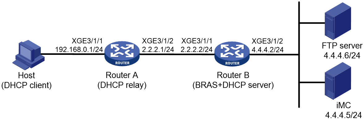
Prerequisites
Configure IP addresses for interfaces, and make sure devices can reach each other at Layer 3. (Details not shown.)
Procedure
1. Configure the DHCP relay agent:
# Enable DHCP.
<RouterA> system-view
[RouterA] dhcp enable
# Enable the DHCP relay agent to record client information in relay entries.
[RouterA] dhcp relay client-information record
# Disable the DHCP relay agent from periodically refreshing dynamic relay entries.
[RouterA] undo dhcp relay client-information refresh enable
# Enable the DHCP relay agent and specify DHCP server address 2.2.2.2 on Ten-GigabitEthernet 3/1/2.
[RouterA] interface ten-gigabitethernet 3/1/2
[RouterA–Ten-GigabitEthernet3/1/2] dhcp select relay
[RouterA–Ten-GigabitEthernet3/1/2] dhcp relay server-address 2.2.2.2
[RouterA–Ten-GigabitEthernet3/1/2] quit
# Configure the default route from the DHCP relay agent to the BRAS.
[RouterA] ip route-static 0.0.0.0 0 2.2.2.2
2. Configure Router B:
a. Configure the DHCP server:
# Enable DHCP.
<RouterB> system-view
[RouterB] dhcp enable
# Enable the DHCP server to return a DHCP-NAK message if the client notions of their IP addresses are incorrect.
[RouterB] dhcp server request-ip-address check
# Create a common IP address pool named pool1 and enter its view.
[RouterB] ip pool pool1
# Specify subnet 192.168.0.0/24 for dynamic allocation in address pool pool1.
[RouterB-ip-pool-pool1] network 192.168.0.0 24
# Specify gateway address 192.168.0.1 in address pool pool1.
[RouterB-ip-pool-pool1] gateway 192.168.0.1
# Specify DNS server address 8.8.8.8 in address pool pool1.
[RouterB-ip-pool-pool1] dns-list 8.8.8.8
# Exclude IP address 192.168.0.1 from dynamic allocation in address pool pool1.
[RouterB-ip-pool-pool1] forbidden-ip 192.168.0.1
[RouterB-ip-pool-pool1] quit
# Configure a static route to the DHCP relay agent.
[RouterB] ip route-static 192.168.0.0 24 2.2.2.1
b. Configure the IP address of the portal authentication server newpt as 4.4.4.5 and the plaintext key 123456.
[RouterB] portal server newpt
[RouterB-portal-server-newpt] ip 4.4.4.5 key simple 123456
[RouterB-portal-server-newpt] quit
c. Specify 11111 as the HTTPS redirect listening port number. Make sure the port number is not used by any other service. To see the TCP port numbers used by other services, execute the display tcp command.
[RouterB] http-redirect https-port 11111
d. Configure the device to get user access information from ARP and ND entries.
[Device] portal access-info trust arp
[Device] portal access-info trust nd
e. Create a local user group named pre.
[RouterB] user-group pre
New user group added.
[RouterB-ugroup-pre] quit
f. Configure ACLs for preauthentication:
# Create an IPv4 advanced ACL named web_permit. Configure a rule to permit all packets destined for the portal server from users in user group pre.
[RouterB] acl advanced name web_permit
[RouterB-acl-ipv4-adv-web_permit] rule 0 permit ip destination 4.4.4.5 0 user-group pre
[RouterB-acl-ipv4-adv-web_permit] quit
# Create an IPv4 advanced ACL named neiwang. Configure a rule to permit all packets destined for the internal network server from users in user group pre.
[RouterB] acl advanced name neiwang
[RouterB-acl-ipv4-adv-neiwang] rule 0 permit ip destination 4.4.4.6 0 user-group pre
[RouterB-acl-ipv4-adv-neiwang] quit
# Create an IPv4 advanced ACL named web_http. Configure a rule to permit TCP packets with the destination port 80 (HTTP packets) from users in user group pre.
[RouterB] acl advanced name web_http
[RouterB-acl-ipv4-adv-web_http] rule 0 permit tcp destination-port eq www user-group pre
[RouterB-acl-ipv4-adv-web_http] quit
# Create an IPv4 advanced ACL named web_https, and configure a rule to permit TCP packets with the destination port 443 (HTTPS packets) from users in user group pre.
[RouterB] acl advanced name web_https
[RouterB-acl-ipv4-adv-web_https] rule 0 permit tcp destination-port eq 443 user-group pre
[RouterB-acl-ipv4-adv-web_https] quit
# Create an IPv4 advanced ACL named ip, and configure a rule to permit IP packets from users in user group pre.
[RouterB] acl advanced name ip
[RouterB-acl-ipv4-adv-ip] rule 0 permit ip user-group pre
[RouterB-acl-ipv4-adv-ip] quit
# Create an IPv4 advanced ACL named neiwang_out, and configure a rule to permit IP packets from the internal network server in user group pre.
[RouterB] acl advanced name neiwang_out
[RouterB-acl-ipv4-adv-neiwang_out] rule 0 permit ip source 4.4.4.6 0 user-group pre
[RouterB-acl-ipv4-adv-neiwang_out] quit
# Create an IPv4 advanced ACL named web_out, and configure a rule to permit IP packets from the portal server in user group pre.
[RouterB] acl advanced name web_out
[RouterB-acl-ipv4-adv-web_out] rule 0 permit ip source 4.4.4.5 0 user-group pre
[RouterB-acl-ipv4-adv-web_out] quit
g. Configure QoS traffic classes for preauthentication users:
# Create the traffic class web_permit and specify ACL web_permit as the match criterion.
[RouterB] traffic classifier web_permit operator and
[RouterB-classifier-web_permit] if-match acl name web_permit
[RouterB-classifier-web_permit] quit
# Create the traffic class neiwang and specify ACL neiwang as the match criterion.
[RouterB] traffic classifier neiwang operator and
[RouterB-classifier-neiwang] if-match acl name neiwang
[RouterB-classifier-neiwang] quit
# Create the traffic class web_http and specify ACL web_http as the match criterion.
[RouterB] traffic classifier web_http operator and
[RouterB-classifier-web_http] if-match acl name web_http
[RouterB-classifier-web_http] quit
# Create the traffic class web_https and specify ACL web_https as the match criterion.
[RouterB] traffic classifier web_https operator and
[RouterB-classifier-web_https] if-match acl name web_https
[RouterB-classifier-web_https] quit
# Create the traffic class ip_cpu and specify ACL ip as the match criterion.
[Device] traffic classifier ip_cpu operator or
[Device-classifier-ip_cpu] if-match acl name ip
[Device-classifier-ip_cpu] if-match acl ipv6 name ip
[Device-classifier-ip_cpu] quit
# Create the traffic class ip_deny and specify ACL ip as the match criterion.
[Device] traffic classifier ip_deny operator or
[Device-classifier-ip_deny] if-match acl name ip
[Device-classifier-ip_deny] if-match acl ipv6 name ip
[Device-classifier-ip_deny] quit
# Create the traffic class neiwang_out and specify ACL neiwang_out as the match criterion.
[RouterB] traffic classifier neiwang_out operator and
[RouterB-classifier-neiwang_out] if-match acl name neiwang_out
[RouterB-classifier-neiwang_out] quit
# Create the traffic class web_out and specify ACL web_out as the match criterion.
[RouterB] traffic classifier web_out operator and
[RouterB-classifier-web_out] if-match acl name web_out
[RouterB-classifier-web_out] quit
h. Configure QoS traffic behaviors:
# Configure the traffic behavior web_permit to permit traffic to pass through without rate limiting or accounting.
[RouterB] traffic behavior web_permit
[RouterB-behavior-web_permit] filter permit
[RouterB-behavior-web_permit] free account
[RouterB-behavior-web_permit] quit
# Configure the traffic behavior neiwang to permit traffic to pass through.
[RouterB] traffic behavior neiwang
[RouterB-behavior-neiwang] filter permit
[RouterB-behavior-neiwang] quit
# Configure the traffic behavior web_http to redirect HTTP packets to the CPU.
[RouterB] traffic behavior web_http
[RouterB-behavior-web_http] redirect http-to-cpu
[RouterB-behavior-web_http] quit
# Configure the traffic behavior web_https to redirect HTTPS packets to the CPU.
[RouterB] traffic behavior web_https
[RouterB-behavior-web_https] redirect https-to-cpu
[RouterB-behavior-web_https] quit
# Configure the traffic behavior web_deny to deny traffic.
[RouterB] traffic behavior web_deny
[RouterB-behavior-web_deny] filter deny
[RouterB-behavior-web_deny] free account
[RouterB-behavior-web_deny] quit
# Configure the traffic behavior neiwang_out to permit traffic to pass through.
[RouterB] traffic behavior neiwang_out
[RouterB-behavior-neiwang_out] filter permit
[RouterB-behavior-neiwang_out] quit
# Configure the traffic behavior web_out to permit traffic without rate limiting or traffic accounting.
[RouterB] traffic behavior web_out
[RouterB-behavior-web_out] filter permit
[RouterB-behavior-web_out] free account
[RouterB-behavior-web_out] quit
i. Configure the QoS policies:
# Create a QoS policy named web.
[RouterB] qos policy web
# Associate the traffic class web_permit with the traffic behavior web_permit.
[RouterB-qospolicy-web] classifier web_permit behavior web_permit
# Associate the traffic class neiwang with the traffic behavior neiwang.
[RouterB-qospolicy-web] classifier neiwang behavior neiwang
# Associate the traffic class web_http with the traffic behavior web_http.
[RouterB-qospolicy-web] classifier web_http behavior web_http
# Associate the traffic class web_https with the traffic behavior web_https.
[RouterB-qospolicy-web] classifier web_https behavior web_https
# Associate the traffic class ip_cpu with the traffic behavior web_cpu.
[Device-qospolicy-web] classifier ip_cpu behavior web_cpu
# Associate the traffic class ip_deny with the traffic behavior web_deny.
[Device-qospolicy-web] classifier ip_deny behavior web_deny
[RouterB-qospolicy-web] quit
# Configure a QoS policy named out.
[RouterB] qos policy out
# Associate the traffic class web_out with the traffic behavior web_out. Associate the traffic class neiwang_out with the traffic behavior neiwang_out. Associate the traffic class web_deny with the traffic behavior web_deny.
[RouterB-qospolicy-out] classifier web_out behavior web_out
[RouterB-qospolicy-out] classifier neiwang_out behavior neiwang_out
[RouterB-qospolicy-out] classifier ip_deny behavior web_deny
[RouterB-qospolicy-out] quit
j. Apply the QoS policies:
# Apply the QoS Policy web to the inbound traffic globally. To identify whether the QoS policy takes effect, execute the display qos policy global inbound command.
[RouterB] qos apply policy web global inbound
# Apply the QoS Policy out to the outbound traffic globally. To identify whether the QoS policy takes effect, execute the display qos policy global outbound command.
[RouterB] qos apply policy out global outbound
k. Configure a RADIUS scheme:
# Create a RADIUS scheme named rs1 and enter its view.
[RouterB] radius scheme rs1
# Configure primary servers and keys for authentication and accounting.
[RouterB-radius-rs1] primary authentication 4.4.4.5
[RouterB-radius-rs1] primary accounting 4.4.4.5
[RouterB-radius-rs1] key authentication simple radius
[RouterB-radius-rs1] key accounting simple radius
# Exclude the ISP name from the username sent to the RADIUS server.
[RouterB-radius-rs1] user-name-format without-domain
[RouterB-radius-rs1] quit
# (Optional.) Enable RADIUS session control. As a best practice, configure this feature when an IMC server acts as the RADIUS server.
[RouterB] radius session-control enable
l. Configure the preauthentication ISP domain and Web authentication ISP domain:
# Configure the ISP domain dm1 for IPoE user preauthentication.
[RouterB] domain name dm1
[RouterB-isp-dm1] authentication ipoe none
[RouterB-isp-dm1] authorization ipoe none
[RouterB-isp-dm1] accounting ipoe none
# Configure the authorized IP address pool and user group in ISP domain dm1.
[RouterB-isp-dm1] authorization-attribute user-group pre
[RouterB-isp-dm1] authorization-attribute ip-pool pool1
# Configure the Web authentication page URL in ISP domain dm1.
[RouterB-isp-dm1] web-server url http://4.4.4.5:8080/portal/
[RouterB-isp-dm1] quit
# Configure the ISP domain dm2 for IPoE user Web authentication.
[RouterB] domain name dm2
[RouterB-isp-dm2] authentication ipoe radius-scheme rs1
[RouterB-isp-dm2] authorization ipoe radius-scheme rs1
[RouterB-isp-dm2] accounting ipoe radius-scheme rs1
[RouterB-isp-dm2] quit
m. Configure IPoE:
# Enable IPoE and configure Layer 3 access mode on Ten-GigabitEthernet 3/1/2.
[RouterB] interface ten-gigabitethernet 3/1/2
[RouterB–Ten-GigabitEthernet3/1/2] ip subscriber routed enable
# Configure Web authentication for IPoE users on Ten-GigabitEthernet 3/1/2.
[RouterB–Ten-GigabitEthernet3/1/2] ip subscriber authentication-method web
The operation may cut all users on this interface. Continue?[Y/N]:y
# Configure the ISP domain dm1 for preauthentication and the ISP domain dm2 for Web authentication on Ten-GigabitEthernet 3/1/2.
[RouterB–Ten-GigabitEthernet3/1/2] ip subscriber pre-auth domain dm1
[RouterB–Ten-GigabitEthernet3/1/2] ip subscriber web-auth domain dm2
# Disable online detection on Ten-GigabitEthernet 3/1/2.
The detection packet type is ARP by default. To use Layer 3 transparent authentication, as a best practice, disable online detection.
[RouterB–Ten-GigabitEthernet3/1/2] undo ip subscriber user-detect ip
[RouterB–Ten-GigabitEthernet3/1/2] quit
n. Configure MAC-based quick portal authentication:
# Create MAC binding server mts.
[RouterB] portal mac-trigger server mts
# Specify the IP address of the MAC binding server as 4.4.4.5.
[RouterB-portal-mac-trigger-server-mts] ip 4.4.4.5
[RouterB-portal-mac-trigger-server-mts] quit
# Specify the MAC binding server mts on Ten-GigabitEthernet 3/1/2.
[RouterB] interface ten-gigabitethernet 3/1/2
[RouterB–Ten-GigabitEthernet3/1/2] portal apply mac-trigger-server mts
[RouterB–Ten-GigabitEthernet3/1/2] quit
3. Configure the RADIUS server:
a. Configure the access device:
- Log in to the IMC platform and click the User tab.
- Select User Access Policy > Access Device Management > Access Device from the navigation tree to open the access device configuration page.
- Click Add to open the page as shown in Figure 96.
- Enter the shared key radius.
- Use the default settings for other parameters.
Figure 96 Adding an access device

- Click Add Manually in the Device List area to open the page as shown in Figure 97.
- Enter the access device's IP address 4.4.4.2.
- Click OK.
Figure 97 Manually adding an access device
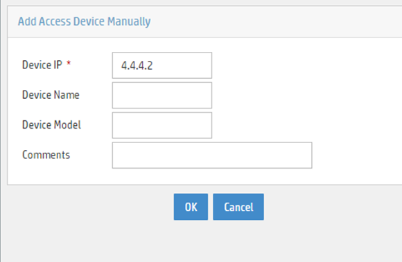
a. Add an access policy:
- Select User Access Policy > Access Policy from the navigation tree to open the access policy page.
- Click Add to open the page as shown in Figure 98.
- Enter the access policy name AccessPolicy.
- Use the default settings for other parameters.
Figure 98 Adding an access policy

a. Add an access service:
- Select User Access Policy > Access Service from the navigation tree to open the access service page.
- Click Add to open the page as shown in Figure 99.
- Enter the service name IPoE_Server.
- Select AccessPolicy from the default access policy list.
- Use the default settings for other parameters.
Figure 99 Adding an access service

a. Add a user:
- Select User Management > Add User from the navigation tree to open the adding user page, as shown in Figure 100.
- Enter the username IPoE_Web001 and the user ID 001.
- Click OK.

a. Add an access user:
- Select Access User > All Access Users from the navigation tree to open the access user page
- Click Add to open the page as shown in Figure 101.
- Select IPoE_Web001 for the username.
- Enter the account name user1.
- Enter the password pass1.
- Select the access service IPoE_Server.
Figure 101 Adding an access user

4. Configure the portal server:
a. Configure the portal homepage:
- Select User Access Policy > Portal Service > Server from the navigation tree to open the portal server configuration page, as shown in Figure 102.
- Click OK.
Figure 102 Portal server configuration page

a. Configure portal authentication source IP address range:
- Select User Access Policy > Portal Service > IP Group from the navigation tree to open the portal IP address group configuration page.
- Click Add to open the page as shown in Figure 103.
- Enter the IP group name IPoE_Web_User.
- Enter the start IP address (192.168.0.1) and end IP address (192.168.0.255) of the IP group. Make sure the host IP address is in the IP group.
- Click OK.
Figure 103 Adding an IP address group

a. Add a portal device:
- Select User Access Policy > Portal Service > Device from the navigation tree to open the portal device configuration page.
- Click Add to open the page as shown in Figure 104.
- Enter the device name NAS.
- Enter the IP address of the portal packets' outgoing interface Ten-GigabitEthernet 3/1/1 (4.4.4.2).
- Enter the key 123456.
- Select Directly Connect for access method.
- Click OK.
Figure 104 Adding a portal device

a. Associate the portal device with the IP address group:
- Click the icon in the Port Group Information Management column of device NAS to open the port group configuration page, as shown in Figure 105.
- Click Add to open the page as shown in Figure 106.
- Enter the port group name group.
- Select the configured IP address group IPoE_Web_User. Make sure the IP address used by the user to access the network is within this IP address group.
- Select Supported in the Transparent Authentication list.
- Click OK.

Figure 106 Port group configuration

a. From the navigation tree, select User Access Manager > Service Parameters > Validate System Configuration to validate the settings.
Verifying the configuration
# Display IPoE session information to verify that the host has passed preauthentication.
[RouterB] display access-user auth-type pre-auth
UserID Interface IP address MAC address S-/C-VLAN
Username IPv6 address Access type
0x33d XGE3/1/2 192.168.0.2 0015-e947-f4d4 -/-
0015e947f4d4 - L3 IPoE dynamic
As shown in Figure 107, the Web login page opens after preauthentication. Enter the username and password on the page.
# Display IPoE session information to verify that the host has passed Web authentication and come online.
[RouterB] display access-user auth-type pre-auth
UserID Interface IP address MAC address S-/C-VLAN
Username IPv6 address Access type
0x33d XGE3/1/2 192.168.0.2 0015-e947-f4d4 -/-
user1@dm2 - L3 IPoE dynamic
# Click Log Out on the Web login page as shown in Figure 107.
# Verify that the user returns to the preauthentication status.
[RouterB] display access-user auth-type pre-auth
UserID Interface IP address MAC address S-/C-VLAN
Username IPv6 address Access type
0x33d XGE3/1/2 192.168.0.2 0015-e947-f4d4 -/-
0015e947f4d4 - L3 IPoE dynamic
# Open the browser, and enter an address randomly, for example, http://63.1.1.240.
# Verify that the user has come online through IPoE Web authentication.
[RouterB] display access-user auth-type web-auth
UserID Interface IP address MAC address S-/C-VLAN
Username IPv6 address Access type
0x33d XGE3/1/2 192.168.0.2 0015-e947-f4d4 -/-
0015e947f4d4 - Web auth
Example: Configuring IPoE transparent MAC authentication (Layer 3 transparent)
Network configuration
As shown in Figure 108, the host accesses the BRAS as a DHCP client though a Layer 3 network. The BRAS also acts as the DHCP server. A server installed with H3C IMC acts as the portal authentication server and the portal Web server. This example uses IMC PLAT 7.1(E0303), IMC UAM 7.1(E0305), and IMC EIP 7.1(E0305). A RADIUS server that supports MAC binding acts as the authentication, authorization, and accounting server and performs MAC binding. The FTP server is an internal network server.

Prerequisites
Configure IP addresses for interfaces, and make sure devices can reach each other at Layer 3. (Details not shown.)
Procedure
1. Configure the DHCP relay agent:
# Enable DHCP.
<RouterA> system-view
[RouterA] dhcp enable
# Enable the DHCP relay agent to record client information in relay entries.
[RouterA] dhcp relay client-information record
# Disable the DHCP relay agent from periodically refreshing dynamic relay entries.
[RouterA] undo dhcp relay client-information refresh enable
# Enable the DHCP relay agent and specify DHCP server address 2.2.2.2 on Ten-GigabitEthernet 3/1/2.
[RouterA] interface ten-gigabitethernet 3/1/2
[RouterA–Ten-GigabitEthernet3/1/2] dhcp select relay
[RouterA–Ten-GigabitEthernet3/1/2] dhcp relay server-address 2.2.2.2
[RouterA–Ten-GigabitEthernet3/1/2] quit
# Configure the default route from the DHCP relay agent to the BRAS.
[RouterA] ip route-static 0.0.0.0 0 2.2.2.2
2. Configure Router B:
a. Configure the DHCP server:
# Enable DHCP.
<RouterB> system-view
[RouterB] dhcp enable
# Enable the DHCP server to return a DHCP-NAK message if the client notions of their IP addresses are incorrect.
[RouterB] dhcp server request-ip-address check
# Create a common IP address pool named pool1 and enter its view.
[RouterB] ip pool pool1
# Specify subnet 192.168.0.0/24 for dynamic allocation in address pool pool1.
[RouterB-ip-pool-pool1] network 192.168.0.0 24
# Specify gateway address 192.168.0.1 in address pool pool1.
[RouterB-ip-pool-pool1] gateway 192.168.0.1
# Specify DNS server address 8.8.8.8 in address pool pool1.
[RouterB-ip-pool-pool1] dns-list 8.8.8.8
# Exclude IP address 192.168.0.1 from dynamic allocation in address pool pool1.
[RouterB-ip-pool-pool1] forbidden-ip 192.168.0.1
[RouterB-ip-pool-pool1] quit
# Configure a static route to the DHCP relay agent.
[RouterB] ip route-static 192.168.0.0 24 2.2.2.1
b. Configure the IP address of the portal authentication server newpt as 4.4.4.5 and the plaintext key 123456.
[RouterB] portal server newpt
[RouterB-portal-server-newpt] ip 4.4.4.5 key simple 123456
[RouterB-portal-server-newpt] quit
c. Specify 11111 as the HTTPS redirect listening port number. Make sure the port number is not used by any other service. To see the TCP port numbers used by other services, execute the display tcp command.
[RouterB] http-redirect https-port 11111
d. Configure the device to get user access information from ARP and ND entries.
[RouterB] portal access-info trust arp
[RouterB] portal access-info trust nd
e. Create a local user group named pre.
[RouterB] user-group pre
New user group added.
[RouterB-ugroup-pre] quit
f. Configure ACLs for preauthentication:
# Create an IPv4 advanced ACL named web_permit. Configure a rule to permit all packets destined for the portal server from users in user group pre.
[RouterB] acl advanced name web_permit
[RouterB-acl-ipv4-adv-web_permit] rule 0 permit ip destination 4.4.4.5 0 user-group pre
[RouterB-acl-ipv4-adv-web_permit] quit
# Create an IPv4 advanced ACL named neiwang. Configure a rule to permit all packets destined for the internal network server from users in user group pre.
[RouterB] acl advanced name neiwang
[RouterB-acl-ipv4-adv-neiwang] rule 0 permit ip destination 4.4.4.6 0 user-group pre
[RouterB-acl-ipv4-adv-neiwang] quit
# Create an IPv4 advanced ACL named web_http. Configure a rule to permit TCP packets with the destination port 80 (HTTP packets) from users in user group pre.
[RouterB] acl advanced name web_http
[RouterB-acl-ipv4-adv-web_http] rule 0 permit tcp destination-port eq www user-group pre
[RouterB-acl-ipv4-adv-web_http] quit
# Create an IPv4 advanced ACL named web_https, and configure a rule to permit TCP packets with the destination port 443 (HTTPS packets) from users in user group pre.
[RouterB] acl advanced name web_https
[RouterB-acl-ipv4-adv-web_https] rule 0 permit tcp destination-port eq 443 user-group pre
[RouterB-acl-ipv4-adv-web_https] quit
# Create an IPv4 advanced ACL named ip, and configure a rule to permit IP packets from users in user group pre.
[RouterB] acl advanced name ip
[RouterB-acl-ipv4-adv-ip] rule 0 permit ip user-group pre
[RouterB-acl-ipv4-adv-ip] quit
# Create an IPv4 advanced ACL named neiwang_out, and configure a rule to permit IP packets from the internal network server in user group pre.
[RouterB] acl advanced name neiwang_out
[RouterB-acl-ipv4-adv-neiwang_out] rule 0 permit ip source 4.4.4.6 0 user-group pre
[RouterB-acl-ipv4-adv-neiwang_out] quit
# Create an IPv4 advanced ACL named web_out, and configure a rule to permit IP packets from the portal server in user group pre.
[RouterB] acl advanced name web_out
[RouterB-acl-ipv4-adv-web_out] rule 0 permit ip source 4.4.4.5 0 user-group pre
[RouterB-acl-ipv4-adv-web_out] quit
g. Configure QoS traffic classes for preauthentication users:
# Create the traffic class web_permit and specify ACL web_permit as the match criterion.
[RouterB] traffic classifier web_permit operator and
[RouterB-classifier-web_permit] if-match acl name web_permit
[RouterB-classifier-web_permit] quit
# Create the traffic class neiwang and specify ACL neiwang as the match criterion.
[RouterB] traffic classifier neiwang operator and
[RouterB-classifier-neiwang] if-match acl name neiwang
[RouterB-classifier-neiwang] quit
# Create the traffic class web_http and specify ACL web_http as the match criterion.
[RouterB] traffic classifier web_http operator and
[RouterB-classifier-web_http] if-match acl name web_http
[RouterB-classifier-web_http] quit
# Create the traffic class web_https and specify ACL web_https as the match criterion.
[RouterB] traffic classifier web_https operator and
[RouterB-classifier-web_https] if-match acl name web_https
[RouterB-classifier-web_https] quit
# Create the traffic class ip_cpu and specify ACL ip as the match criterion.
[RouterB] traffic classifier ip_cpu operator or
[RouterB-classifier-ip_cpu] if-match acl name ip
[RouterB-classifier-ip_cpu] if-match acl ipv6 name ip
[RouterB-classifier-ip_cpu] quit
# Create the traffic class ip_deny and specify ACL ip as the match criterion.
[RouterB] traffic classifier ip_deny operator or
[RouterB-classifier-ip_deny] if-match acl name ip
[RouterB-classifier-ip_deny] if-match acl ipv6 name ip
[RouterB-classifier-ip_deny] quit
# Create the traffic class neiwang_out and specify ACL neiwang_out as the match criterion.
[RouterB] traffic classifier neiwang_out operator and
[RouterB-classifier-neiwang_out] if-match acl name neiwang_out
[RouterB-classifier-neiwang_out] quit
# Create the traffic class web_out and specify ACL web_out as the match criterion.
[RouterB] traffic classifier web_out operator and
[RouterB-classifier-web_out] if-match acl name web_out
[RouterB-classifier-web_out] quit
h. Configure QoS traffic behaviors:
# Configure the traffic behavior web_permit to permit traffic to pass through without rate limiting or accounting.
[RouterB] traffic behavior web_permit
[RouterB-behavior-web_permit] filter permit
[RouterB-behavior-web_permit] free account
[RouterB-behavior-web_permit] quit
# Configure the traffic behavior neiwang to permit traffic to pass through.
[RouterB] traffic behavior neiwang
[RouterB-behavior-neiwang] filter permit
[RouterB-behavior-neiwang] quit
# Configure the traffic behavior web_http to redirect HTTP packets to the CPU.
[RouterB] traffic behavior web_http
[RouterB-behavior-web_http] redirect http-to-cpu
[RouterB-behavior-web_http] quit
# Configure the traffic behavior web_https to redirect HTTPS packets to the CPU.
[RouterB] traffic behavior web_https
[RouterB-behavior-web_https] redirect https-to-cpu
[RouterB-behavior-web_https] quit
# Configure the traffic behavior web_deny to deny traffic.
[RouterB] traffic behavior web_deny
[RouterB-behavior-web_deny] filter deny
[RouterB-behavior-web_deny] free account
[RouterB-behavior-web_deny] quit
# Configure the traffic behavior neiwang_out to permit traffic to pass through.
[RouterB] traffic behavior neiwang_out
[RouterB-behavior-neiwang_out] filter permit
[RouterB-behavior-neiwang_out] quit
# Configure the traffic behavior web_out to permit traffic without rate limiting or traffic accounting.
[RouterB] traffic behavior web_out
[RouterB-behavior-web_out] filter permit
[RouterB-behavior-web_out] free account
[RouterB-behavior-web_out] quit
i. Configure the QoS policies:
# Create a QoS policy named web.
[RouterB] qos policy web
# Associate the traffic class web_permit with the traffic behavior web_permit.
[RouterB-qospolicy-web] classifier web_permit behavior web_permit
# Associate the traffic class neiwang with the traffic behavior neiwang.
[RouterB-qospolicy-web] classifier neiwang behavior neiwang
# Associate the traffic class web_http with the traffic behavior web_http.
[RouterB-qospolicy-web] classifier web_http behavior web_http
# Associate the traffic class web_https with the traffic behavior web_https.
[RouterB-qospolicy-web] classifier web_https behavior web_https
# Associate the traffic class ip_cpu with the traffic behavior web_cpu.
[RouterB-qospolicy-web] classifier ip_cpu behavior web_cpu
# Associate the traffic class ip_deny with the traffic behavior web_deny.
[RouterB-qospolicy-web] classifier ip_deny behavior web_deny
[RouterB-qospolicy-web] quit
# Configure a QoS policy named out.
[RouterB] qos policy out
# Associate the traffic class web_out with the traffic behavior web_out. Associate the traffic class web_out with the traffic behavior web_out. Associate the traffic class web_deny with the traffic behavior web_deny.
[RouterB-qospolicy-out] classifier web_out behavior web_out
[RouterB-qospolicy-out] classifier neiwang_out behavior neiwang_out
[RouterB-qospolicy-out] classifier ip_deny behavior web_deny
[RouterB-qospolicy-out] quit
j. Apply the QoS policies:
# Apply the QoS Policy web to the inbound traffic globally. To identify whether the QoS policy takes effect, execute the display qos policy global inbound command.
[RouterB] qos apply policy web global inbound
# Apply the QoS Policy out to the outbound traffic globally. To identify whether the QoS policy takes effect, execute the display qos policy global outbound command.
[RouterB] qos apply policy out global outbound
k. Configure a RADIUS scheme:
# Create a RADIUS scheme named rs1 and enter its view.
[RouterB] radius scheme rs1
# Configure primary servers and keys for authentication and accounting.
[RouterB-radius-rs1] primary authentication 4.4.4.1
[RouterB-radius-rs1] primary accounting 4.4.4.1
[RouterB-radius-rs1] key authentication simple radius
[RouterB-radius-rs1] key accounting simple radius
# Exclude the ISP name from the username sent to the RADIUS server.
[RouterB-radius-rs1] user-name-format without-domain
[RouterB-radius-rs1] quit
# (Optional.) Enable RADIUS session control. As a best practice, configure this feature when an IMC server acts as the RADIUS server.
[RouterB] radius session-control enable
l. Configure the preauthentication ISP domain and Web authentication ISP domain:
# Configure the ISP domain dm1 for IPoE user preauthentication.
[RouterB] domain name dm1
[RouterB-isp-dm1] authentication ipoe none
[RouterB-isp-dm1] authorization ipoe none
[RouterB-isp-dm1] accounting ipoe none
# Configure the authorized IP address pool and user group in ISP domain dm1.
[RouterB-isp-dm1] authorization-attribute user-group pre
[RouterB-isp-dm1] authorization-attribute ip-pool pool1
# Configure the Web authentication page URL in ISP domain dm1.
[RouterB-isp-dm1] web-server url http://4.4.4.5:8080/portal/
[RouterB-isp-dm1] quit
# Configure the ISP domain dm2 for IPoE user Web authentication.
[RouterB] domain name dm2
[RouterB-isp-dm2] authentication ipoe radius-scheme rs1
[RouterB-isp-dm2] authorization ipoe radius-scheme rs1
[RouterB-isp-dm2] accounting ipoe radius-scheme rs1
[RouterB-isp-dm2] quit
m. Configure IPoE:
# Enable IPoE and configure Layer 3 access mode on Ten-GigabitEthernet 3/1/2.
[RouterB] interface ten-gigabitethernet 3/1/2
[RouterB–Ten-GigabitEthernet3/1/2] ip subscriber routed enable
# Configure Web MAC authentication for IPoE users on Ten-GigabitEthernet 3/1/2.
[RouterB–Ten-GigabitEthernet3/1/2] ip subscriber authentication-method web mac-auth
The operation may cut all users on this interface. Continue?[Y/N]:y
# Configure the ISP domain dm1 for preauthentication and the ISP domain dm2 for preauthentication on Ten-GigabitEthernet 3/1/2.
[RouterB–Ten-GigabitEthernet3/1/2] ip subscriber pre-auth domain dm1
[RouterB–Ten-GigabitEthernet3/1/2] ip subscriber web-auth domain dm2
# Disable online detection on Ten-GigabitEthernet 3/1/2.
The detection packet type is ARP by default. To use Layer 3 transparent authentication, as a best practice, disable online detection.
[RouterB–Ten-GigabitEthernet3/1/2] undo ip subscriber user-detect ip
[RouterB–Ten-GigabitEthernet3/1/2] quit
3. Configure the RADIUS server.
For more information about configuring AAA and MAC binding on the RADIUS server, see the configuration guide for the RADIUS server.
4. Configure the portal server:
a. Configure the portal homepage:
- Select User Access Policy > Portal Service > Server from the navigation tree to open the portal server configuration page, as shown in Figure 109.
- Click OK.
Figure 109 Portal server configuration page

a. Configure portal authentication source IP address range:
- Select User Access Policy > Portal Service > IP Group from the navigation tree to open the portal IP address group configuration page.
- Click Add to open the page as shown in Figure 110.
- Enter the IP group name IPoE_Web_User.
- Enter the start IP address (192.168.0.1) and end IP address (192.168.0.255) of the IP group. Make sure the host IP address is in the IP group.
- Click OK.
Figure 110 Adding an IP address group

a. Add a portal device:
- Select User Access Policy > Portal Service > Device from the navigation tree to open the portal device configuration page.
- Click Add to open the page as shown in Figure 111.
- Enter the device name NAS.
- Enter the IP address of the portal packets' outgoing interface Ten-GigabitEthernet 3/1/1 (4.4.4.2).
- Enter the key 123456.
- Select Directly Connect for access method.
- Click OK.
Figure 111 Adding a portal device

a. Associate the portal device with the IP address group:
- Click the icon in the Port Group Information Management column of device NAS to open the port group configuration page, as shown in Figure 112.
- Click Add to open the page as shown in Figure 113.
- Enter the port group name group.
- Select the configured IP address group IPoE_Web_User. Make sure the IP address used by the user to access the network is within this IP address group.
- Click OK.

Figure 113 Port group configuration

Verifying the configuration
# Display IPoE session information to verify that the host has passed preauthentication.
[RouterB] display access-user auth-type pre-auth
UserID Interface IP address MAC address S-/C-VLAN
Username IPv6 address Access type
0x33d XGE3/1/2 192.168.0.2 0015-e947-f4d4 -/-
0015e947f4d4 - L3 IPoE dynamic
As shown in Figure 114, the Web login page opens after preauthentication. Enter the username and password on the page.
# Display IPoE session information to verify that the host has passed Web authentication and come online.
[RouterB] display access-user auth-type web-auth
UserID Interface IP address MAC address S-/C-VLAN
Username IPv6 address Access type
0x33d XGE3/1/2 192.168.0.2 0015-e947-f4d4 -/-
user1@dm2 - Web auth
# Click Log Out on the page as shown in Figure 114.
# Verify that the user returns to the preauthentication status.
[RouterB] display access-user auth-type pre-auth
UserID Interface IP address MAC address S-/C-VLAN
Username IPv6 address Access type
0x33d XGE3/1/2 192.168.0.2 0015-e947-f4d4 -/-
0015e947f4d4 - L3 IPoE dynamic
# Open the browser, and enter any address in the address bar to access http://63.1.1.240/. Display session information. The output shows that the user has come online through Web authentication.
[RouterB] display access-user auth-type web-auth
UserID Interface IP address MAC address S-/C-VLAN
Username IPv6 address Access type
0x33d XGE3/1/2 192.168.0.2 0015-e947-f4d4 -/-
0015e947f4d4 - Web auth
Example: Configuring IPoE Web authentication with EAP
Network configuration
As shown in Figure 115, the host accesses the BRAS as a DHCP client through a Layer 2 device. It obtains configuration information from the DHCP server through the BRAS. A server installed with H3C IMC acts as the RADIUS server, the portal authentication server, and the portal Web server. This example uses IMC PLAT 7.1(E0303), IMC UAM 7.1(E0305), and IMC EIP 7.1(E0305).
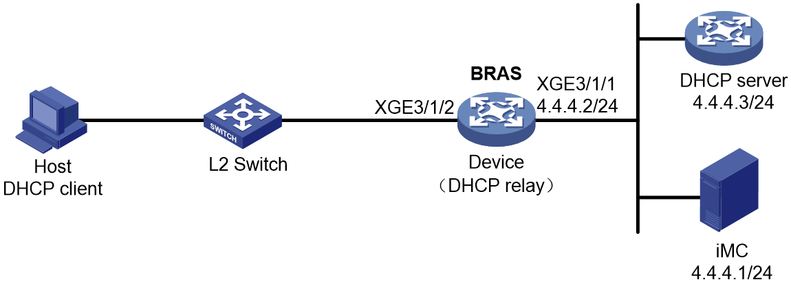
Prerequisites
Configure IP addresses for interfaces, and make sure devices can reach each other at Layer 3. (Details not shown.)
Procedure
1. Configure the DHCP server:
# Enable DHCP.
<DHCP-server> system-view
[DHCP-server] dhcp enable
# Enable the DHCP server to return a DHCP-NAK message if the client notions of their IP addresses are incorrect.
[DHCP-server] dhcp server request-ip-address check
# Create an IP address pool named pool1 and enter its view.
[DHCP-server] ip pool pool1
# Specify primary subnet 192.168.0.0/24 for dynamic allocation in address pool pool1.
[DHCP-server-ip-pool-pool1] network 192.168.0.0 24
# Specify gateway address 192.168.0.1 in address pool pool1.
[DHCP-server-ip-pool-pool1] gateway-list 192.168.0.1
# Specify DNS server address 8.8.8.8 in address pool pool1.
[DHCP-server-ip-pool-pool1] dns-list 8.8.8.8
# Exclude IP address 192.168.0.1 from dynamic allocation in address pool pool1.
[DHCP-server-ip-pool-pool1] forbidden-ip 192.168.0.1
[DHCP-server-ip-pool-pool1] quit
# Configure the default route.
[DHCP-server] ip route-static 0.0.0.0 0 4.4.4.2
2. Configure the BRAS:
a. Configure the DHCP relay agent:
# Enable DHCP.
<Device> system-view
[Device] dhcp enable
# Enable the DHCP relay agent on Ten-GigabitEthernet 3/1/2.
[Device] interface ten-gigabitethernet 3/1/2
[Device–Ten-GigabitEthernet3/1/2] dhcp select relay
[Device–Ten-GigabitEthernet3/1/2] quit
# Create a remote BAS IP address pool named pool1.
[Device] ip pool pool1 bas remote
# Specify gateway address 192.168.0.1 in address pool pool1.
[Device-ip-pool-pool1] gateway 192.168.0.1 24
# Exclude IP address 192.168.0.1 from dynamic allocation in address pool pool1.
[Device-ip-pool-pool1] forbidden-ip 192.168.0.1
# Specify DHCP server 4.4.4.3 in address pool pool1.
[Device-ip-pool-pool1] remote-server 4.4.4.3
[Device-ip-pool-pool1] quit
b. Configure the IP address of the portal authentication server newpt as 4.4.4.1 and the plaintext key 123456.
[Device] portal server newpt
[Device-portal-server-newpt] ip 4.4.4.1 key simple 123456
[Device-portal-server-newpt] quit
c. Configure a RADIUS scheme:
# Create a RADIUS scheme named rs1 and enter its view.
[Device] radius scheme rs1
# Configure primary servers and keys for authentication and accounting.
[Device-radius-rs1] primary authentication 4.4.4.1
[Device-radius-rs1] primary accounting 4.4.4.1
[Device-radius-rs1] key authentication simple 123456
[Device-radius-rs1] key accounting simple 123456
# Exclude the ISP name from the username sent to the RADIUS server.
[Device-radius-rs1] user-name-format without-domain
[Device-radius-rs1] quit
# (Optional.) Enable RADIUS session control. As a best practice, configure this feature when an IMC server acts as the RADIUS server.
[Device] radius session-control enable
d. Configure the preauthentication ISP domain and Web authentication ISP domain:
# Configure the ISP domain dm1 for IPoE user preauthentication.
[Device] domain name dm1
[Device-isp-dm1] authentication ipoe none
[Device-isp-dm1] authorization ipoe none
[Device-isp-dm1] accounting ipoe none
# Configure the authorized IP address pool and user group in ISP domain dm1.
[Device-isp-dm1] authorization-attribute user-group pre
[Device-isp-dm1] authorization-attribute ip-pool pool1
# Configure the Web authentication page URL and Web server IP address in ISP domain dm1.
[Device-isp-dm1] web-server url http://4.4.4.1:8080/portal/
[Device-isp-dm1] web-server ip 4.4.4.1
[Device-isp-dm1] quit
# Configure the ISP domain dm2 for IPoE user Web authentication.
[Device] domain name dm2
[Device-isp-dm2] authentication ipoe radius-scheme rs1
[Device-isp-dm2] authorization ipoe radius-scheme rs1
[Device-isp-dm2] accounting ipoe radius-scheme rs1
[Device-isp-dm2] quit
e. Configure IPoE:
# Enable IPoE and configure Layer 2 access mode on Ten-GigabitEthernet 3/1/2.
[Device] interface ten-gigabitethernet 3/1/2
[Device–Ten-GigabitEthernet3/1/2] ip subscriber l2-connected enable
# Configure Web authentication for IPoE users on Ten-GigabitEthernet 3/1/2.
[Device–Ten-GigabitEthernet3/1/2] ip subscriber authentication-method web
The operation may cut all users on this interface. Continue?[Y/N]:y
# Configure the ISP domain dm1 for preauthentication and the ISP domain dm2 for Web authentication on Ten-GigabitEthernet 3/1/2.
[Device–Ten-GigabitEthernet3/1/2] ip subscriber pre-auth domain dm1
[Device–Ten-GigabitEthernet3/1/2] ip subscriber web-auth domain dm2
[Device–Ten-GigabitEthernet3/1/2] quit
3. Configure the RADIUS server:
a. Configure the access device:
- Log in to the IMC platform and click the User tab.
- Select User Access Policy > Access Device Management > Access Device from the navigation tree to open the access device configuration page.
- Click Add to open the page as shown in Figure 116.
- Enter the shared key radius.
- Use the default settings for other parameters.
Figure 116 Adding an access device
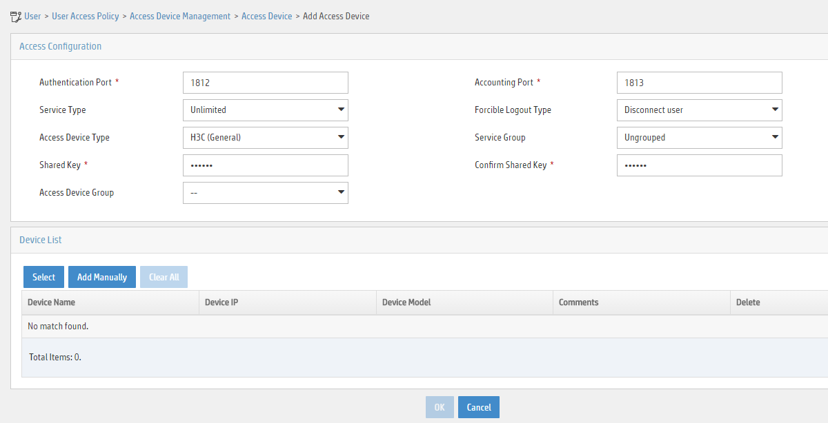
- Click Add Manually in the Device List area to open the page as shown in Figure 117.
- Enter the access device's IP address 4.4.4.2.
- Click OK.
Figure 117 Manually adding an access device

a. Add an access policy:
- Select User Access Policy > Access Policy from the navigation tree to open the access policy page.
- Click Add to open the page as shown in Figure 118.
- Enter the access policy name.
- Select EAP for Certificate Authentication.
- Use the default settings for other parameters.
- Click OK.
Figure 118 Adding an access policy
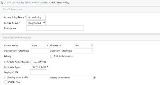
a. Add an access service:
- Select User Access Policy > Access Service from the navigation tree to open the access service page.
- Click Add to open the page as shown in Figure 119.
- Enter the service name.
- Select AccessPolicy from the Default Access Policy list.
- Use the default settings for other parameters.
- Click OK.
Figure 119 Adding an access service
a. Add an access user:
- Select Access User > All Access Users from the navigation tree to open the access user page.
- Click Add to open the page as shown in Figure 120.
- Select an access user.
- Set the password.
- Click OK.
Figure 120 Adding an access user
# Select User Access Policy > Service Parameters > Validate System Configuration from the navigation tree to validate the configurations.
4. Configure the portal server:
a. Configure the portal homepage:
- Select User Access Policy > Portal Service > Server from the navigation tree to open the portal server configuration page, as shown in Figure 121.
- Click OK.
Figure 121 Portal server configuration page
a. Configure portal authentication source IP address range:
- Select User Access Policy > Portal Service > IP Group from the navigation tree to open the portal IP address group configuration page.
- Click Add to open the page as shown in Figure 122.
- Enter the IP group name IPoE_Web_User.
- Enter the start IP address (192.168.0.1) and end IP address (192.168.0.255) of the IP group. Make sure the host IP address is in the IP group.
- Click OK.
Figure 122 Adding an IP address group

a. Add a portal device:
- Select User Access Policy > Portal Service > Device from the navigation tree to open the portal device configuration page.
- Click Add to open the page as shown in Figure 123.
- Enter the device name NAS.
- Enter the IP address of the portal packets' outgoing interface Ten-GigabitEthernet 3/1/1 (4.4.4.2).
- Enter the key 123456.
- Select Directly Connect for access method.
- Click OK.
Figure 123 Adding a portal device

a. Associate the portal device with the IP address group:
- Click the icon in the Port Group Information Management column of device NAS to open the port group configuration page, as shown in Figure 124.
- Click Add to open the page as shown in Figure 125.
- Enter the port group name group.
- Select the configured IP address group IPoE_Web_User. Make sure the IP address used by the user to access the network is within this IP address group.
- Select EAP from the Authentication Type list.
- Click OK.
Figure 125 Port group configuration
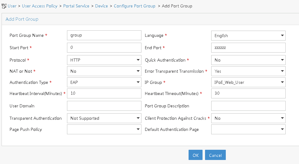
a. From the navigation tree, select User Access Manager > Service Parameters > Validate System Configuration to validate the settings.
Verifying the configuration
# Display IPoE session information to verify that the host has passed preauthentication.
[Device] display access-user auth-type pre-auth
UserID Interface IP address MAC address S-/C-VLAN
Username IPv6 address Access type
0x33d XGE3/1/2 192.168.0.2 0015-e947-f4d4 -/-
0015e947f4d4 - L2 IPoE dynamic
# As shown in Figure 126, open the iNode login page after preauthentication. Enter the server address, the username, and the password on the page. Click the dropdown arrow next to Disconnect. The page shown in Figure 127 opens.
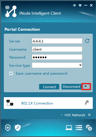
# As shown in Figure 127, select Certificate Authentication in the Enable advanced authentication list and select an authentication type (EAP-TLS in this example) in the Advanced tab of the Properties dialog box. In the Certificate Options area, click Client Certificate, select a certificate on the window that opens, and select Validate server certificate chain.
Figure 127 Setting iNode client attribute
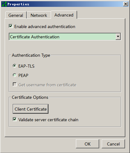
# After the configuration of iNode client attribute, click OK to return to the iNode client authentication page.
# Click Connect on the iNode authentication page to perform EAP authentication. Display IPoE session information to verify that the host has passed Web authentication and come online.
[Device] display access-user auth-type web-auth
UserID Interface IP address MAC address S-/C-VLAN
Username IPv6 address Access type
0x33d XGE3/1/2 192.168.0.2 0015-e947-f4d4 -/-
client - Web auth
# Click Disconnect on the iNode login page as shown in Figure 126.
# Verify that the user returns to the preauthentication status.
[Device] display access-user auth-type pre-auth
UserID Interface IP address MAC address S-/C-VLAN
Username IPv6 address Access type
0x33d XGE3/1/2 192.168.0.2 0015-e947-f4d4 -/-
0015e947f4d4 - L2 IPoE dynamic
Example: Configuring IPoE 802.1X authentication
Network configuration
As shown in Figure 128:
· An 802.1X client accesses the BRAS in IPoE mode through a Layer 2 network.
· The BRAS acts a DHCP relay agent to request IP addresses from the remote DHCP server.
· The FTP server is an internal network server.

Prerequisites
Configure IP addresses for interfaces, and make sure devices can reach each other at Layer 3.
Procedure
1. Configure the RADIUS server:
|
|
NOTE: This section uses the Linux Free RADIUS server as an example. |
# Configure the RADIUS client. Add the following contents to the clients.conf file.
client 4.4.4.2/32 {
ipaddr = 4.4.4.2
netmask=32
secret=radius
}
The contents above configure the RADIUS client IP address as 4.4.4.2 and configure the shared key as radius.
# Configure users. Add the username and password to the users user information file. The username is user1 and the password is pass1.
user1 Cleartext-Password :="pass1"
2. Configure the DHCP server:
# Enable DHCP globally.
<DHCP-server> system-view
[DHCP-server] dhcp enable
# Enable the DHCP server to return a DHCP-NAK message if the client notions of their IP addresses are incorrect.
[DHCP-server] dhcp server request-ip-address check
# Create address pool pool1 and enter its view.
[DHCP-server] ip pool pool1
# Specify primary subnet 192.168.0.0/24 for dynamic allocation in the address pool. Specify gateway address 192.168.0.1 and DNS server address 8.8.8.8 in the address pool.
[DHCP-server-ip-pool-pool1] network 192.168.0.0 24
[DHCP-server-ip-pool-pool1] gateway-list 192.168.0.1
[DHCP-server-dhcp-pool-pool1] dns-list 8.8.8.8
# Exclude IP address 192.168.0.1 from dynamic allocation.
[DHCP-server-ip-pool-pool1] forbidden-ip 192.168.0.1
[DHCP-server-ip-pool-pool1] quit
# Configure the default route.
[DHCP-server] ip route-static 0.0.0.0 0 4.4.4.2
3. Configure Device:
a. Configure the DHCP relay agent:
# Enable DHCP globally.
<Device> system-view
[Device] dhcp enable
# Enable recording client information in relay entries.
[Device] dhcp relay client-information record
# Disable the DHCP relay agent from periodically refreshing dynamic relay entries.
[Device] undo dhcp relay client-information refresh enable
# Enter the view of interface Ten-GigabitEthernet 3/1/2.
[Device] interface ten-gigabitethernet 3/1/2
# Enable the DHCPv4 relay agent on the interface.
[Device–Ten-GigabitEthernet3/1/2] dhcp select relay
[Device–Ten-GigabitEthernet3/1/2] quit
# Create remote BAS IP address pool pool1, and specify the gateway address, excluded IP address, and DHCP server for the address pool.
[Device] ip pool pool1 bas remote
[Device-ip-pool-pool1] gateway 192.168.0.1 24
[Device-ip-pool-pool1] forbidden-ip 192.168.0.1
[Device-ip-pool-pool1] remote-server 4.4.4.3
[Device-ip-pool-pool1] quit
b. Create a user group named dot1x for the preauthentication domain.
[Device] user-group dot1x
New user group added.
[Device-ugroup-dot1x] quit
c. Configure the ACLs for users in the preauthentication domain:
# Configure IPv4 advanced ACL neiwang to match packets destined to the internal network server for users in user group dot1x.
[Device] acl advanced name neiwang
[Device-acl-ipv4-adv-neiwang] rule 0 permit ip destination 4.4.4.6 0 user-group dot1x
[Device-acl-ipv4-adv-neiwang] quit
# Configure IPv4 advanced ACL ip to match IP packets for users in user group dot1x.
[Device] acl advanced name ip
[Device-acl-ipv4-adv-ip] rule 0 permit ip user-group dot1x
[Device-acl-ipv4-adv-ip] quit
# Configure IPv4 advanced ACL neiwang_out to match packets sourced from the internal network server for users in user group dot1x.
[Device] acl advanced name neiwang_out
[Device-acl-ipv4-adv-neiwang_out] rule 0 permit ip source 4.4.4.6 0 user-group dot1x
[Device-acl-ipv4-adv-neiwang_out] quit
d. Configure traffic classes for users in the preauthentication domain:
# Create a traffic class named neiwang, and use ACL neiwang as the match criterion.
[Device] traffic classifier neiwang operator and
[Device-classifier-neiwang] if-match acl name neiwang
[Device-classifier-neiwang] quit
# Create a traffic class named dot1x_deny, and use ACL ip as the match criterion.
[Device] traffic classifier dot1x_deny operator and
[Device-classifier-dot1x_deny] if-match acl name ip
[Device-classifier-dot1x_deny] quit
# Create a traffic class named neiwang_out, and use ACL neiwang_out as the match criterion.
[Device] traffic classifier neiwang_out operator and
[Device-classifier-neiwang_out] if-match acl name neiwang_out
[Device-classifier-neiwang_out] quit
e. Configure traffic behaviors:
# Configure a traffic behavior named neiwang to permit packets.
[Device] traffic behavior neiwang
[Device-behavior-neiwang] filter permit
[Device-behavior-neiwang] quit
# Create a traffic behavior named dot1x_deny to deny packets.
[Device] traffic behavior dot1x_deny
[Device-behavior-dot1x_deny] filter deny
[Device-behavior-dot1x_deny] free account
[Device-behavior-dot1x_deny] quit
# Configure a traffic behavior named neiwang_out to permit packets.
[Device] traffic behavior neiwang_out
[Device-behavior-neiwang_out] filter permit
[Device-behavior-neiwang_out] quit
f. Configure QoS policies:
# Configure a QoS policy named dot1x for inbound traffic.
[Device] qos policy dot1x
# Associate traffic classes with traffic behaviors to permit packets destined to the internal network server and deny any other packets for users in user group dot1x.
[Device-qospolicy-dot1x] classifier neiwang behavior neiwang
[Device-qospolicy-dot1x] classifier dot1x_deny behavior dot1x_deny
[Device-qospolicy-dot1x] quit
# Configure a QoS policy named out for outbound traffic.
[Device] qos policy out
# Associate traffic classes with traffic behaviors to permit packet sourced from the internal network server and deny any other packets for users in user group dot1x.
[Device-qospolicy-out] classifier neiwang_out behavior neiwang_out
[Device-qospolicy-out] classifier dot1x_deny behavior dot1x_deny
[Device-qospolicy-out] quit
g. Apply QoS policies:
# Apply QoS policy dot1x to the received user traffic.
[Device] qos apply policy dot1x global inbound
# Apply QoS policy out to the online user traffic sent.
[Device] qos apply policy out global outbound
h. Configure a RADIUS scheme:
# Create RADIUS scheme rs1, and enter its view.
[Device] radius scheme rs1
# Configure primary servers and keys for authentication and accounting.
[Device-radius-rs1] primary authentication 4.4.4.5
[Device-radius-rs1] primary accounting 4.4.4.5
[Device-radius-rs1] key authentication simple radius
[Device-radius-rs1] key accounting simple radius
# Exclude the ISP name from the username sent to the RADIUS server.
[Device-radius-rs1] user-name-format without-domain
[Device-radius-rs1] quit
i. Configure the preauthentication domain and 802.1X authentication domain:
# Configure the preauthentication domain for IPoE users.
[Device] domain name dm1
[Device-isp-dm1] authentication ipoe none
[Device-isp-dm1] authorization ipoe none
[Device-isp-dm1] accounting ipoe none
# Configure the authorized address pool and user group in the preauthentication domain.
[Device-isp-dm1] authorization-attribute user-group dot1x
[Device-isp-dm1] authorization-attribute ip-pool pool1
# Configure the 802.1X authentication domain for IPoE users.
[Device] domain name dot1x
[Device-isp-dot1x] authentication lan-access radius-scheme rs1
[Device-isp-dot1x] authorization lan-access radius-scheme rs1
[Device-isp-dot1x] accounting lan-access radius-scheme rs1
# Configure the authorized address pool. (This step is required when 802.1X authentication is prioritized and optional in this example.)
[Device-isp-dot1x] authorization-attribute ip-pool pool1
[Device-isp-dot1x] quit
j. Configure IPoE:
# Enable IPoE and configure the Layer 2 access mode.
[Device] interface ten-gigabitethernet 3/1/2
[Device–Ten-GigabitEthernet3/1/2] ip subscriber l2-connected enable
# Configure the 802.1X authentication method for IPoE users.
[Device–Ten-GigabitEthernet3/1/2] ip subscriber authentication-method dot1x
The operation might cut all users on this interface. Continue?[Y/N]:y
# Configure the preauthentication domain as dm1 and 802.1X authentication domain as dot1x.
[Device–Ten-GigabitEthernet3/1/2] ip subscriber pre-auth domain dm1
[Device–Ten-GigabitEthernet3/1/2] dot1x mandatory-domain dot1x
[Device–Ten-GigabitEthernet3/1/2] quit
Verifying the configuration
# After a user passes preauthentication, use the following command to view online IPoE user information. The output shows that the user obtains IP address 192.168. 0.2.
[Device] display access-user interface ten-gigabitethernet 3/1/2
UserID Interface IP address MAC address S-/C-VLAN
Username IPv6 address Access type
0x5c XGE3/1/2 192.168.0.2 000c-29a6-b656 -/-
000c29a6b656 - L2 IPoE dynamic
# An 802.1X client uses username user1 and password pass1 to perform 802.1X authentication. Use the following command to view online IPoE user information.
[Device] display access-user interface ten-gigabitethernet 3/1/2
UserID Interface IP address MAC address S-/C-VLAN
Username IPv6 address Access type
0x5c XGE3/1/2 192.168.0.2 000c-29a6-b656 -/-
user1 - L2 IPoE dynamic
Example: Configuring IPoE common Web authentication for dual-stack users (URL allowlist)
Network configuration
As shown in Figure 129, the host accesses the BRAS as a DHCP client though a Layer 2 device. It obtains configuration information from the DHCP server through the BRAS. The BRAS performs AAA for the host through the RADIUS server. A server installed with H3C IMC acts as the RADIUS server, the portal authentication server, and the portal Web server. This example uses IMC PLAT 7.1(E0303), IMC UAM 7.1(E0305), and IMC EIP 7.1(E0305). The FTP server is an internal network server. Limit the access rate to 5 Mbps for the user after passing Web authentication.
When a student does not pass IPoE Web authentication or has passed IPoE Web authentication but has owed fees, the student is still allowed to access the internal websites of the campus. In this way, the student can still learn and communicate normally.
When a student owes fees, the student is still allowed to access the payment page of the service provider and pay the charge on the payment page pushed by the service provider. In this way, the student can quickly restore access to Internet.

Analysis
To ensure that an unauthenticated or defaulting user can still access the internal websites of the campus and actively pay the charge, you can configure the object group-based URL allowlist and add the internal websites of the campus (FTP server and IMC server in this example) and the payment page address (https://www.alipay.com/xxx in this example) to the URL allowlist.
To facilitate QoS policy-based control for users, assign users to different user groups based on their states:
· Preauthentication users: In this phase, users have not passed IPoE Web authentication and need access control. Assign these users to the user group named pre.
· Defaulting users: Defaulting users need access control. Assign these users to the user group named qianfei.
· Normal users: These users do not need access control. Assign these users to the user group named web.
For users in user group pre and user group qianfei, perform the following QoS policy-based controls separately:
· Users in user group pre
¡ Can access the addresses on the URL allowlist.
¡ When a user accesses an address not on the URL allowlist through HTTP or HTTPS, all requests are redirected to the Web authentication page (http://www.ipv4web.com or http://www.ipv6.web.com in this example), and the other traffic is dropped.
· Users in user group qianfei
¡ Can access the addresses on the URL allowlist.
¡ When a user accesses an address not on the URL allowlist through HTTP or HTTPS, all requests are redirected to the payment page (https://www.alipay.com/xxx in this example), and the other traffic is dropped.
Prerequisites
Configure the DNS server correctly, so that the server can parse the IPv4 URL or IPv6 URL for the Web authentication page http://www.ipv4.web.com or http://www.ipv6.web.com based on the first stack through which dual-stack IPoE users come online. (Details not shown.)
Configure IP addresses for interfaces, and make sure devices can reach each other at Layer 3. (Details not shown.)
You must use this feature together with AAA. Before configuring this feature, make sure the AAA server supports H3C private attributes 246 (H3C-Auth-Detail-Result) and 250 (H3C-WEB-URL) and can assign these attributes to defaulting users.
Attribute 246 (H3C-Auth-Detail-Result) indicates the user authentication result details. Possible values for the attribute include:
· 0: Normal user. In this case, the server will cancel assigning attribute 250 and allow the user to access any network resources.
· 1: Defaulting user. In this case, the server will assign attribute 250 and allow the user to access network resources on the URL allowlist. If the user accesses other network resources, the requests will be redirected to the URL defined in attribute 250.
· 2: User whose broadband usage has expired. In this case, the server will assign attribute 250. The first Web access request of the user will be redirected to the URL defined in attribute 250.
Attribute 250 (H3C-WEB-URL) is used to carry the Web redirection URL for users, and is used together with attribute 246.
Procedure
1. Configure the DHCP servers:
a. Configure an IP address pool:
# Enable DHCP.
<DHCP-server> system-view
[DHCP-server] dhcp enable
# Enable the DHCP server to return a DHCP-NAK message if the client notions of their IP addresses are incorrect.
[DHCP-server] dhcp server request-ip-address check
# Create an IPv4 address pool named pool1 and enter its view.
[DHCP-server] ip pool pool1
# Specify primary subnet 192.168.0.0/24 for dynamic allocation and DNS server 8.8.8.8 in address pool pool1.
[DHCP-server-ip-pool-pool1] network 192.168.0.0 24
[DHCP-server-ip-pool-pool1] dns-list 8.8.8.8
# Specify gateway address 192.168.0.1 in address pool pool1.
[DHCP-ip-pool-pool1] gateway-list 192.168.0.1
# Exclude IP address 192.168.0.1 from dynamic allocation in address pool pool1.
[DHCP-server-ip-pool-pool1] forbidden-ip 192.168.0.1
[DHCP-server-ip-pool-pool1] quit
# Configure the default route.
[DHCP-server] ip route-static 0.0.0.0 0 4.4.4.2
b. Configure an IPv6 address pool:
# Create an IPv6 address pool named pool2 and enter its view.
[DHCP-server] ipv6 pool pool2
# Specify primary subnet 192::/64 for dynamic allocation and DNS server 8::8 in address pool pool2.
[DHCP-server-ipv6-pool-pool2] network 192::/64
[DHCP-server-ipv6-pool-pool2] dns-server 8::8
[DHCP-server-ipv6-pool-pool2] quit
# Exclude IP address 192::1 from dynamic allocation in address pool pool2.
[DHCP-server] ipv6 dhcp server forbidden-address 192::1
# Enable the DHCPv6 server on Ten-GigabitEthernet 3/1/1.
[DHCP-server] interface ten-gigabitethernet 3/1/1
[DHCP-server-Ten-GigabitEthernet3/1/1] ipv6 dhcp select server
[DHCP-server-Ten-GigabitEthernet3/1/1] quit
# Configure the default route.
[DHCP-server] ipv6 route-static :: 0 4::2
2. Configure the BRAS:
a. Configure the DHCP relay agent:
# Enable DHCP.
<Device> system-view
[Device] dhcp enable
# Create a remote BAS IP address pool named pool1.
[Device] ip pool pool1 bas remote
# Specify gateway address 192.168.0.1 in address pool pool1.
[Device-ip-pool-pool1] gateway 192.168.0.1 24
# Exclude IP address 192.168.0.1 from dynamic allocation in address pool pool1.
[Device-ip-pool-pool1] forbidden-ip 192.168.0.1
# Specify DHCP server 4.4.4.3 in address pool pool1.
[Device-ip-pool-pool1] remote-server 4.4.4.3
[Device-ip-pool-pool1] quit
# Create a remote IPv6 address pool named pool2.
[Device] ipv6 pool pool2
# Specify gateway address 192::1 in address pool pool2.
[Device-ipv6-pool-pool2] gateway-list 192::1
# Specify IPv6 subnet 192::/64 in address pool pool2.
[Device-ipv6-pool-pool2] network 192::/64 export-route
# Specify DHCP server 4::3 in address pool pool2.
[Device-ipv6-pool-pool2] remote-server 4::3
[Device-ipv6-pool-pool2] quit
# Enable the DHCPv4 relay agent on Ten-GigabitEthernet 3/1/2.
[Device] interface ten-gigabitethernet 3/1/2
[Device–Ten-GigabitEthernet3/1/2] dhcp select relay
# Automatically generate a link-local address for Ten-GigabitEthernet 3/1/2.
[Device–Ten-GigabitEthernet3/1/2] ipv6 address auto link-local
# Enable the DHCPv6 relay agent on Ten-GigabitEthernet 3/1/2.
[Device–Ten-GigabitEthernet3/1/2] ipv6 dhcp select relay
# Disable RA message suppression on Ten-GigabitEthernet 3/1/2.
[Device–Ten-GigabitEthernet3/1/2] undo ipv6 nd ra halt
# Set the managed address configuration flag (M) to 1 in RA advertisements to be sent. Then, the host uses a DHCPv6 server to obtain IPv6 addresses.
[Device–Ten-GigabitEthernet3/1/2] ipv6 nd autoconfig managed-address-flag
# Set the other stateful configuration flag (O) to 1 in RA advertisements to be sent. Then, the host uses a DHCPv6 server to obtain configuration information other than IPv6 addresses.
[Device–Ten-GigabitEthernet3/1/2] ipv6 nd autoconfig other-flag
# Disable Ten-GigabitEthernet 3/1/2 from advertising the specified prefix in RA messages, preventing the endpoint from obtaining a temporary IPv6 address. In an IPv6 network, an endpoint might use a temporary IPv6 address for IPoE Web authentication, which will cause authentication failure.
[Device–Ten-GigabitEthernet3/1/2] ipv6 nd ra prefix 192::/64 no-advertise
[Device–Ten-GigabitEthernet3/1/2] quit
b. Configure the portal servers:
# Configure the IP address of the IPv4 portal authentication server newpt1 as 4.4.4.5 and the plaintext key 123456.
[Device] portal server newpt1
[Device-portal-server-newpt1] ip 4.4.4.5 key simple 123456
[Device-portal-server-newpt1] quit
# Configure the IPv6 address of the IPv6 portal authentication server newpt2 as 4::5 and the plaintext key 123456.
[Device] portal server newpt2
[Device-portal-server-newpt2] ipv6 4::5 key simple 123456
[Device-portal-server-newpt2] quit
c. Specify 11111 as the HTTPS redirect listening port number. Make sure the port number is not used by any other service. To see the TCP port numbers used by other services, execute the display tcp command.
[Device] http-redirect https-port 11111
d. Configure the device to get user access information from ARP and ND entries.
[Device] portal access-info trust arp
[Device] portal access-info trust nd
e. Create local user groups:
# Create a local user group named pre for preauthentication users.
[Device] user-group pre
New user group added.
[Device-ugroup-pre] quit
# Create a user group named qianfei for defaulting users.
[Device] user-group qianfei
New user group added.
[Device-ugroup-qianfei] quit
# Create a user group named web.
[Device] user-group web
New user group added.
[Device-ugroup-web] quit
f. Configure URL allowlists:
# Create an IP address object group (URL allowlist) named freeurl_ipv4, and add the internal websites of the campus and the payment page to the URL allowlist.
[Device] object-group ip address freeurl_ipv4
[Device-obj-grp-ip-freeurl_ipv4] network host address 4.4.4.1 //FTP server address
[Device-obj-grp-ip-freeurl_ipv4] network host address 4.4.4.5 //iMC server address
[Device-obj-grp-ip-freeurl-ipv4] network host name https://www.alipay.com/xxx //Payment page address
[Device-obj-grp-ip-freeurlipv4] quit
# Create an IPv6 address object group (URL allowlist) named freeurl_ipv6, and add the internal websites of the campus and the payment page to the URL allowlist.
[Device] object-group ipv6 address freeurl_ipv6
[Device-obj-grp-ipv6-freeurl_ipv6] network host address 4::1 //FTP server address
[Device-obj-grp-ipv6-freeurl_ipv6] network host address 4::5 //iMC server address
[Device-obj-grp-ipv6-freeurl_ipv6] network host name https://www.alipay.com/xxx //Payment page address
[Device-obj-grp-ipv6-freeurl_ipv6] quit
g. Configure common ACLs for URL allowlists, which apply to both preauthentication users and defaulting users:
# Create the following rules for IPv4 and IPv6 advanced ACLs freeurl_permit_in separately to allow packets from users in user group pre and user group qianfei to the addresses on the allowlist.
[Device] acl advanced name freeurl_permit_in
[Device-acl-ipv4-adv-freeurl_permit_in] rule 10 permit ip destination object-group freeurl_ipv4 user-group pre
[Device-acl-ipv4-adv-freeurl_permit_in] rule 20 permit ip destination object-group freeurl_ipv4 user-group qianfei
[Device-acl-ipv4-adv-freeurl_permit_in] quit
[Device] acl ipv6 advanced name freeurl_permit_in
[Device-acl-ipv6-adv-freeurl_permit_in] rule 10 permit ipv6 destination object-group freeurl_ipv6 user-group pre
[Device-acl-ipv6-adv-freeurl_permit_in] rule 20 permit ipv6 destination object-group freeurl_ipv6 user-group qianfei
[Device-acl-ipv6-adv-freeurl_permit_in] quit
# Create the following rules for IPv4 and IPv6 advanced ACLs freeurl_permit_out separately to match packets that users in user group pre and user group qianfei receive from the addresses on the allowlist.
[Device] acl advanced name freeurl_permit_out
[Device-acl-ipv4-adv-freeurl_permit_out] rule 10 permit ip source object-group freeurl_ipv4 user-group pre
[Device-acl-ipv4-adv-freeurl_permit_out] rule 20 permit ip source object-group freeurl_ipv4 user-group qianfei
[Device-acl-ipv4-adv-freeurl_permit_out] quit
[Device] acl ipv6 advanced name freeurl_permit_out
[Device-acl-ipv6-adv-freeurl_permit_out] rule 10 permit ipv6 source object-group freeurl_ipv6 user-group pre
[Device-acl-ipv6-adv-freeurl_permit_out] rule 20 permit ipv6 source object-group freeurl_ipv6 user-group qianfei
[Device-acl-ipv6-adv-freeurl_permit_out] quit
h. Configure ACLs for preauthentication:
# Create an IPv4 and IPv6 advanced ACL named web_http separately. Configure a rule to permit TCP packets with the destination port 80 (HTTP packets) from users in user group pre.
[Device] acl advanced name web_http
[Device-acl-ipv4-adv-web_http] rule 0 permit tcp destination-port eq www user-group pre
[Device-acl-ipv4-adv-web_http] quit
[Device] acl ipv6 advanced name web_http
[Device-acl-ipv6-adv-web_http] rule 0 permit tcp destination-port eq www user-group pre
[Device-acl-ipv6-adv-web_http] quit
# Create an IPv4 and IPv6 advanced ACL named web_https separately, and configure a rule to permit TCP packets with the destination port 443 (HTTPS packets) from users in user group pre.
[Device] acl advanced name web_https
[Device-acl-ipv4-adv-web_https] rule 0 permit tcp destination-port eq 443 user-group pre
[Device-acl-ipv4-adv-web_https] quit
[Device] acl ipv6 advanced name web_https
[Device-acl-ipv6-adv-web_https] rule 0 permit tcp destination-port eq 443 user-group pre
[Device-acl-ipv6-adv-web_https] quit
# Create an IPv4 and IPv6 advanced ACL named ip separately, and configure a rule to permit IP packets from users in user group pre.
[Device] acl advanced name ip
[Device-acl-ipv4-adv-ip] rule 0 permit ip user-group pre
[Device-acl-ipv4-adv-ip] quit
[Device] acl ipv6 advanced name ip
[Device-acl-ipv6-adv-ip] rule 0 permit ipv6 user-group pre
[Device-acl-ipv6-adv-ip] quit
i. Configure the ACLs for defaulting users:
# Create the following rules for IPv4 and IPv6 advanced ACLs qianfei_web_http separately to match TCP packets that users in user group qianfei use to access port 80, HTTP packets.
[Device] acl advanced name qianfei_web_http
[Device-acl-ipv4-adv-qianfei_web_http] rule 0 permit tcp destination-port eq www user-group qianfei
[Device-acl-ipv4-adv-qianfei_web_http] quit
[Device] acl ipv6 advanced name qianfei_web_http
[Device-acl-ipv6-adv-qianfei_web_http] rule 0 permit tcp destination-port eq www user-group qianfei
[Device-acl-ipv6-adv-qianfei_web_http] quit
# Create the following rules for IPv4 and IPv6 advanced ACLs qianfei_web_https separately to match packets that users in user group qianfei use to access port 443, HTTPS packets.
[Device] acl advanced name qianfei_web_https
[Device-acl-ipv4-adv-qianfei_web_https] rule 0 permit tcp destination-port eq 443 user-group qianfei
[Device-acl-ipv4-adv-qianfei_web_https] quit
[Device] acl ipv6 advanced name qianfei_web_https
[Device-acl-ipv6-adv-qianfei_web_https] rule 0 permit tcp destination-port eq 443 user-group qianfei
[Device-acl-ipv6-adv-qianfei_web_https] quit
# Create the following rules for IPv4 and IPv6 advanced ACLs qianfei_ip separately to match IP packets of users in user group qianfei.
[Device] acl advanced name qianfei_ip
[Device-acl-ipv4-adv-qianfei_ip] rule 0 permit ip user-group qianfei
[Device-acl-ipv4-adv-qianfei_ip] quit
[Device] acl ipv6 advanced name qianfei_ip
[Device-acl-ipv6-adv-qianfei_ip] rule 0 permit ipv6 user-group qianfei
[Device-acl-ipv6-adv-qianfei_ip] quit
j. Configure common traffic classes for URL allowlists, which apply to both preauthentication users and defaulting users:
# Create a traffic class named freeurl_permit_in, and use ACL freeurl_permit_in as the match criterion.
[Device] traffic classifier freeurl_permit_in operator or
[Device-classifier-freeurl_permit_in] if-match acl name freeurl_permit_in
[Device-classifier-freeurl_permit_in] if-match acl ipv6 name freeurl_permit_in
[Device-classifier-freeurl_permit_in] quit
# Create a traffic class named freeurl_permit_out, and use ACL freeurl_permit_out as the match criterion.
[Device] traffic classifier freeurl_permit_out operator or
[Device-classifier-freeurl_permit_out] if-match acl name freeurl_permit_out
[Device-classifier-freeurl_permit_out] if-match acl ipv6 name freeurl_permit_out
[Device-classifier-freeurl_permit_out] quit
k. Configure QoS traffic classes for preauthentication users:
# Create the traffic class web_http and specify ACL web_http as the match criterion.
[Device] traffic classifier web_http operator or
[Device-classifier-web_http] if-match acl name web_http
[Device-classifier-web_http] if-match acl ipv6 name web_http
[Device-classifier-web_http] quit
# Create the traffic class web_https and specify ACL web_https as the match criterion.
[Device] traffic classifier web_https operator or
[Device-classifier-web_https] if-match acl name web_https
[Device-classifier-web_https] if-match acl ipv6 name web_https
[Device-classifier-web_https] quit
# Create the traffic class web_deny and specify ACL ip as the match criterion.
[Device] traffic classifier web_deny operator or
[Device-classifier-web_deny] if-match acl name ip
[Device-classifier-web_deny] if-match acl ipv6 name ip
[Device-classifier-web_deny] quit
l. Configure the traffic classes for defaulting users:
# Create a traffic class named qianfei_web_http and use ACL qianfei_web_http as the match criterion.
[Device] traffic classifier qianfei_web_http operator or
[Device-classifier-qianfei_web_http] if-match acl name qianfei_web_http
[Device-classifier-qianfei_web_http] if-match acl ipv6 name qianfei_web_http
[Device-classifier-qianfei_web_http] quit
# Create a traffic class named qianfei_web_https, and use ACL qianfei_web_https as the match criterion.
[Device] traffic classifier qianfei_web_https operator or
[Device-classifier-qianfei_web_https] if-match acl name qianfei_web_https
[Device-classifier-qianfei_web_https] if-match acl ipv6 name qianfei_web_https
[Device-classifier-qianfei_web_https] quit
# Create a traffic class named qianfei_web_deny, and use ACL qianfei_ip as the match criterion.
[Device] traffic classifier qianfei_web_deny operator or
[Device-classifier-qianfei_web_deny] if-match acl name qianfei_ip
[Device-classifier-qianfei_web_deny] if-match acl ipv6 name qianfei_ip
[Device-classifier-qianfei_web_deny] quit
m. Configure common traffic behaviors for URL allowlists, which apply to both preauthentication users and defaulting users:
# Create a traffic behavior named freeurl_permit_in, and allow users in user group pre and user group qianfei to access the addresses on the allowlist.
[Device] traffic behavior freeurl_permit_in
[Device-behavior-freeurl_permit_in] filter permit
[Device-behavior-freeurl_permit_in] free account
[Device-behavior-freeurl_permit_in] quit
# Create a traffic behavior named freeurl_permit_out, and allow packets from the addresses on the allowlist to users in user group pre and user group qianfei.
[Device] traffic behavior freeurl_permit_out
[Device-behavior-freeurl_permit_out] filter permit
[Device-behavior-freeurl_permit_out] free account
[Device-behavior-freeurl_permit_out] quit
n. Configure QoS traffic behaviors for preauthentication users:
# Configure the traffic behavior web_http to redirect HTTP packets to the CPU.
[Device] traffic behavior web_http
[Device-behavior-web_http] redirect http-to-cpu
[Device-behavior-web_http] quit
# Configure the traffic behavior web_https to redirect HTTPS packets to the CPU.
[Device] traffic behavior web_https
[Device-behavior-web_https] redirect https-to-cpu
[Device-behavior-web_https] quit
# Configure the traffic behavior web_deny to deny traffic.
[Device] traffic behavior web_deny
[Device-behavior-web_deny] filter deny
[Device-behavior-web_deny] free account
[Device-behavior-web_deny] quit
o. Configure traffic behaviors for defaulting users:
# Create a traffic behavior named qianfei_web_http, and redirect TCP packets that users in user group qianfei use to access port 80 (HTTP packets) to the CPU.
[Device] traffic behavior qianfei_web_http
[Device-behavior-qianfei_web_http] redirect http-to-cpu
[Device-behavior-qianfei_web_http] quit
# Create a traffic behavior named qianfei_web_https, and redirect TCP packets that users in user group qianfei use to access port 443 (HTTPS packets) to the CPU.
[Device] traffic behavior qianfei_web_https
[Device-behavior-qianfei_web_https] redirect https-to-cpu
[Device-behavior-qianfei_web_https] quit
# Create a traffic behavior named qianfei_web_deny, and deny all IP packets from the users in user group qianfei.
[Device] traffic behavior qianfei_web_deny
[Device-behavior-qianfei_web_deny] filter deny
[Device-behavior-qianfei_web_deny] free account
[Device-behavior-qianfei_web_deny] quit
p. Configure the QoS policies:
# Permit the traffic from users in user group pre and user group qianfei to the addresses on the allowlist to pass through. Then, when a student does not pass IPoE Web authentication or has passed IPoE Web authentication but has owed fees, the student is still allowed to access the internal websites of the campus and access the payment page to pay the charge. In this way, the student can still learn and communicate normally.
[Device-qospolicy-web] classifier freeurl_permit_in behavior freeurl_permit_in
# Redirect the HTTP packets from users in user group pre to the Web authentication page.
[Device-qospolicy-web] classifier web_http behavior web_http
# Redirect the HTTPS packets from users in user group pre to the Web authentication page.
[Device-qospolicy-web] classifier web_https behavior web_https
# Redirect the HTTP packets from users in user group qianfei to the payment page.
[Device-qospolicy-web] classifier qianfei_web_http behavior qianfei_web_http
# Redirect the HTTPS packets from users in user group qianfei to the payment page.
[Device-qospolicy-web] classifier qianfei_web_https behavior qianfei_web_https
# Drop all the other traffic from users in user group pre.
[Device-qospolicy-web] classifier web_deny behavior web_deny
# Drop all the other traffic from users in user group qianfei.
[Device-qospolicy-web] classifier qianfei_web_deny behavior qianfei_web_deny
[Device-qospolicy-web] quit
# Configure an outbound QoS policy named out.
[Device] qos policy out
# Allow packets from the addresses on the allowlist to users in user group pre and user group qianfei to pass through.
[Device-qospolicy-out] classifier freeurl_permit_out behavior freeurl_permit_out
# Drop all the other traffic from users in user group pre.
[Device-qospolicy-out] classifier web_deny behavior web_deny
# Drop all the other traffic from users in user group qianfei.
[Device-qospolicy-out] classifier qianfei_web_deny behavior qianfei_web_deny
[Device-qospolicy-out] quit
q. Apply the QoS policies:
# Apply the QoS Policy web to the inbound traffic globally. To identify whether the QoS policy takes effect, execute the display qos policy global inbound command.
[Device] qos apply policy web global inbound
# Apply the QoS Policy out to the outbound traffic globally. To identify whether the QoS policy takes effect, execute the display qos policy global outbound command.
[Device] qos apply policy out global outbound
r. Configure a RADIUS scheme:
# Create a RADIUS scheme named rs1 and enter its view.
[Device] radius scheme rs1
# Configure primary servers and keys for authentication and accounting.
[Device-radius-rs1] primary authentication 4.4.4.5
[Device-radius-rs1] primary accounting 4.4.4.5
[Device-radius-rs1] key authentication simple radius
[Device-radius-rs1] key accounting simple radius
# Exclude the ISP name from the username sent to the RADIUS server.
[Device-radius-rs1] user-name-format without-domain
[Device-radius-rs1] quit
# (Optional.) Enable RADIUS session control. As a best practice, configure this feature when an IMC server acts as the RADIUS server.
[Device] radius session-control enable
# Set the IP address of the RADIUS DAE client to 4.4.4.5, and set the shared key to radius for the RADIUS DAE client to exchange DAE packets.
[Device] radius dynamic-author server
[Device-radius-da-server] client ip 4.4.4.5 key simple radius
[Device-radius-da-server] quit
s. Configure the preauthentication ISP domain and Web authentication ISP domain:
# Configure the ISP domain dm1 for IPoE user preauthentication.
[Device] domain name dm1
[Device-isp-dm1] authentication ipoe none
[Device-isp-dm1] authorization ipoe none
[Device-isp-dm1] accounting ipoe none
# Configure the authorized user group and IP address pools in preauthentication ISP domain dm1.
[Device-isp-dm1] authorization-attribute user-group pre
[Device-isp-dm1] authorization-attribute ip-pool pool1
[Device-isp-dm1] authorization-attribute ipv6-pool pool2
# Configure the Web authentication page URL in ISP domain dm1.
[Device-isp-dm1] web-server url http://www.ipv4.web.com
[Device-isp-dm1] web-server ipv6-url http://www.ipv6.web.com
[Device-isp-dm1] quit
# Configure the ISP domain dm2 for IPoE user Web authentication, and authorize a CAR policy and a user group.
[Device] domain name dm2
[Device-isp-dm2] authentication ipoe radius-scheme rs1
[Device-isp-dm2] authorization ipoe radius-scheme rs1
[Device-isp-dm2] accounting ipoe radius-scheme rs1
[Device-isp-dm2] authorization-attribute car inbound cir 5120 outbound cir 5120
[Device-isp-dm2] authorization-attribute user-group web
[Device-isp-dm2] quit
t. Configure IPoE:
# Enable IPoE and configure Layer 2 access mode on Ten-GigabitEthernet 3/1/2.
[Device] interface ten-gigabitethernet 3/1/2
[Device–Ten-GigabitEthernet3/1/2] ip subscriber l2-connected enable
# Configure Web authentication for IPoE users on Ten-GigabitEthernet 3/1/2.
[Device–Ten-GigabitEthernet3/1/2] ip subscriber authentication-method web
The operation may cut all users on this interface. Continue?[Y/N]:y
# Configure the ISP domain dm1 for preauthentication and the ISP domain dm2 for Web authentication on Ten-GigabitEthernet 3/1/2.
[Device–Ten-GigabitEthernet3/1/2] ip subscriber pre-auth domain dm1
[Device–Ten-GigabitEthernet3/1/2] ip subscriber web-auth domain dm2
[Device–Ten-GigabitEthernet3/1/2] quit
3. Configure the RADIUS server:
a. Configure the access device:
- Log in to the IMC platform and click the User tab.
- Select User Access Policy > Access Device Management > Access Device from the navigation tree to open the access device configuration page.
- Click Add to open the page as shown in Figure 130.
- Enter the shared key radius.
- Use the default settings for other parameters.
Figure 130 Adding an access device

- Click Add Manually in the Device List area to open the page as shown in Figure 131.
- Enter the access device's IP address 4.4.4.2.
- Click OK.
Figure 131 Manually adding an access device

a. Add an access policy:
- Select User Access Policy > Access Policy from the navigation tree to open the access policy page.
- Click Add to open the page as shown in Figure 132.
- Enter the access policy name AccessPolicy.
- Use the default settings for other parameters.
Figure 132 Adding an access policy

a. Add an access service:
- Select User Access Policy > Access Service from the navigation tree to open the access service page.
- Click Add to open the page as shown in Figure 133.
- Enter the service name IPoE_Server.
- Select AccessPolicy from the default access policy list.
- Use the default settings for other parameters.
Figure 133 Adding an access service

a. Add a user:
- Select User Management > Add User from the navigation tree to open the adding user page, as shown in Figure 134.
- Enter the username IPoE_Web001 and the user ID 001.
- Click OK.

a. Add an access user:
- Select Access User > All Access Users from the navigation tree to open the access user page.
- Click Add to open the page as shown in Figure 135.
- Select IPoE_Web001 for the username.
- Enter the account name user1.
- Enter the password pass1.
- Select the access service IPoE_Server.
Figure 135 Adding an access user

4. Configure the portal server:
a. Configure the portal homepage:
- Select User Access Policy > Portal Service > Server from the navigation tree to open the portal server configuration page, as shown in Figure 136.
- Click OK.
Figure 136 Portal server configuration page

a. Configure portal authentication source IP address range:
- Select User Access Policy > Portal Service > IP Group from the navigation tree to open the portal IP address group configuration page.
- Click Add to open the page as shown in Figure 137.
- Enter the IP group name IPoE_Web_User.
- Enter the start IP address (192.168.0.1) and end IP address (192.168.0.255) of the IP group. Make sure the host IP address is in the IP group.
- Click OK.
Figure 137 Adding an IP address group (IPv4)

- Select User Access Policy > Portal Service > IP Group from the navigation tree to open the portal IP address group configuration page.
- Click Add to open the page as shown in Figure 138.
- Enter the IP group name IPoE_Web_User-2.
- Select Yes from the IPv6 list.
- Enter the start IP address (192::1) and end IP address (192::FFFF) of the IP group. Make sure the host IPv6 address is in the IP group.
- Click OK.
Figure 138 Adding an IP address group (IPv6)
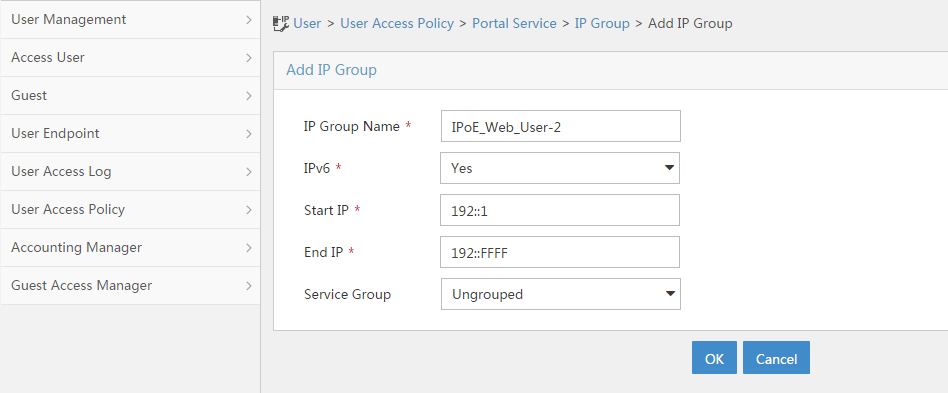
a. Add portal devices:
- Select User Access Policy > Portal Service > Device from the navigation tree to open the portal device configuration page.
- Click Add to open the page as shown in Figure 139.
- Enter the device name NAS.
- Enter the IP address of the portal packets' outgoing interface Ten-GigabitEthernet 3/1/2 (4.4.4.2).
- Enter the key 123456.
- Select Directly Connect for the access method.
- Click OK.
Figure 139 Adding a portal device (IPv4)

- Select User Access Policy > Portal Service > Device from the navigation tree to open the portal device configuration page.
- Click Add to open the page as shown in Figure 140.
- Enter the device name NAS-2.
- Select Portal 3.0 from the Version list.
- Enter the IP address of the portal packets' outgoing interface Ten-GigabitEthernet 3/1/2 (4::2).
- Enter the key 123456.
- Select Directly Connect for access method.
- Click OK.
Figure 140 Adding a portal device (IPv6)

a. Associate the portal device with the IP address group:
- Select User Access Policy > Portal Service > Device from the navigation tree to open the portal device configuration page.
- Click the icon in the Port Group Information Management column of device NAS to open the port group configuration page, as shown in Figure 141.
- Click Add to open the page as shown in Figure 142.
- Enter the port group name group.
- Select the configured IP address group IPoE_Web_User. Make sure the IP address used by the user to access the network is within this IP address group.
- Click OK.

Figure 142 Port group configuration (IPv4)
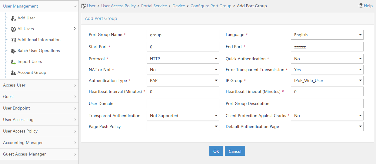
- Select User Access Policy > Portal Service > Device from the navigation tree to open the portal device configuration page.
- Click the icon in the Port Group Information Management column of device NAS-2 to open the port group configuration page, as shown in Figure 141.
- Click Add to open the page as shown in Figure 143.
- Enter the port group name group-2.
- Select the configured IP address group IPoE_Web_User-2. Make sure the IPv6 address used by the user to access the network is within this IPv6 address group.
- Click OK.
Figure 143 Port group configuration (IPv6)

Verifying the configuration
# Display IPoE session information to verify that the host has passed preauthentication and obtained IPv4 address 192.168.0.2 and IPv6 address 192::2.
[Device] display access-user auth-type pre-auth
UserID Interface IP address MAC address S-/C-VLAN
Username IPv6 address Access type
0x33d XGE3/1/2 192.168.0.2 0015-e947-f4d4 -/-
0015e947f4d4 192::2 L2 IPoE dynamic
As shown in Figure 144, the Web login page opens after preauthentication. Enter the username and password on the page.
# Display IPoE session information to verify that the host has passed Web authentication and come online.
[Device] display access-user auth-type web-auth
UserID Interface IP address MAC address S-/C-VLAN
Username IPv6 address Access type
0x33d XGE3/1/2 192.168.0.2 0015-e947-f4d4 -/-
user1@dm2 192::2 Web auth
# When a user owes fee, the AAA server assigns the following attributes to the user:
user-name =user1@dm2 , H3C-User-Group = qianfei,h3c-web-url = "www.alipay.com/xxx",H3C-Auth_Detail_Result = 1
Where, each attributes are explained as follows:
· user-name =user1@dm2 //The username of the defaulting user is user1@dm2.
· H3C-User-Group = qianfei //The user group named qianfei is assigned to the defaulting user.
· H3C-Auth-Detail-Result=1 //The value 1 means the user is a defaulting user and can access only addresses on the URL allowlist. When the user accesses an address not on the URL allowlist through HTTP or HTTPS, the packets are redirected to the website specified in the H3C-WEB-URL attribute.
· H3c-WEB-URL="https://www.alipay.com/xxx" //This attribute specifies the website to which packets from the defaulting user are redirected.
In this case, the user can access only addresses on the URL allowlist through HTTP. When the user accesses an address not on the URL allowlist through HTTP, the packets are redirected to the website https://www.alipay.com/xxx. For example, when you enter http://www.163.com/ in the address bar of a browser, you are redirected to the payment page.
# After the user pays the charge, the AAA server assigns the following attributes to the user:
user-name =user1@dm2 , H3C-User-Group =web ,H3C-Auth_Detail_Result = 0
Where, each attributes are explained as follows:
· user-name =user1@dm2 //The username of the user who has paid the charge is user1@dm2.
· H3C-User-Group = web //The user group named web is assigned to the user who has paid the charge, and the user is removed user group qianfei.
· H3C-Auth-Detail-Result=0 //The value 0 means the redirection action is canceled for the user.
In this case, the user can access any network resources. For example, when you enter http://www.baidu.com/ in the address bar of a browser, the page opens normally.
Example: Configuring IPoE common Web authentication and intelligent multi-egress for dual-stack users
Network configuration
As shown in Figure 145, the host accesses the BRAS as a DHCP client though a Layer 2 device. It obtains configuration information from the DHCP server through the BRAS. The BRAS performs AAA for the host through the RADIUS server. A server installed with H3C IMC acts as the RADIUS server, the portal authentication server, and the portal Web server. This example uses IMC PLAT 7.1(E0303), IMC UAM 7.1(E0305), and IMC EIP 7.1(E0305). The FTP server is an internal network server. Limit the access rate to 5 Mbps for the user after passing Web authentication.
Allow a user to come online in the IPv6 protocol stack only when the user has passed Web authentication and come online in the IPv4 protocol stack. Additionally, an IPv6 address is assigned according to the attributes authorized to the IPv4 protocol stack.

Prerequisites
Configure IP addresses for interfaces, and make sure devices can reach each other at Layer 3. (Details not shown.)
Procedure
1. Configure the DNS server.
Configure the DNS server properly, so that the server can parse the IPv4 URL or IPv6 URL corresponding to the Web authentication page http://www.ipv4.web.com or http://www.ipv6.web.com according to the first protocol stack that comes online of the IPoE dual-stack user. (Details not shown.)
2. Configure the DHCP servers:
a. Configure an IP address pool:
# Enable DHCP.
<DHCP-server> system-view
[DHCP-server] dhcp enable
# Enable the DHCP server to return a DHCP-NAK message if the client notions of their IP addresses are incorrect.
[DHCP-server] dhcp server request-ip-address check
# Create an IPv4 address pool named pool1 and enter its view.
[DHCP-server] ip pool pool1
# Specify primary subnet 192.168.0.0/24 for dynamic allocation and DNS server 8.8.8 in address pool pool1.
[DHCP-server-ip-pool-pool1] network 192.168.0.0 24
[DHCP-server-ip-pool-pool1] dns-list 8.8.8.8
# Specify gateway address 192.168.0.1 in address pool pool1.
[DHCP-server-ip-pool-pool1] gateway-list 192.168.0.1
# Exclude IP address 192.168.0.1 from dynamic allocation in address pool pool1.
[DHCP-server-ip-pool-pool1] forbidden-ip 192.168.0.1
[DHCP-server-ip-pool-pool1] quit
# Configure the default route.
[DHCP-server] ip route-static 0.0.0.0 0 4.4.4.2
b. Configure an IPv6 address pool:
# Create an IPv6 address pool named pool2 and enter its view.
[DHCP-server] ipv6 pool pool2
# Specify primary subnet 192::/64 for dynamic allocation and DNS server 8::8 in address pool pool2.
[DHCP-server-ipv6-pool-pool2] network 192::/64
[DHCP-server-ipv6-pool-pool2] dns-server 8::8
[DHCP-server-ipv6-pool-pool2] quit
# Exclude IP address 192::1 from dynamic allocation in address pool pool2.
[DHCP-server] ipv6 dhcp server forbidden-address 192::1
# Enable the DHCPv6 server on Ten-GigabitEthernet 3/1/1.
[DHCP-server] interface ten-gigabitethernet 3/1/1
[DHCP-server-Ten-GigabitEthernet3/1/1] ipv6 dhcp select server
[DHCP-server-Ten-GigabitEthernet3/1/1] quit
# Configure the default route.
[DHCP-server] ipv6 route-static :: 0 4::2
3. Configure the BRAS:
a. Configure the DHCP relay agent:
# Enable DHCP.
<Device> system-view
[Device] dhcp enable
# Create a remote BAS IP address pool named pool1.
[Device] ip pool pool1 bas remote
# Specify gateway address 192.168.0.1 in address pool pool1.
[Device-ip-pool-pool1] gateway 192.168.0.1 24
# Exclude IP address 192.168.0.1 from dynamic allocation in address pool pool1.
[Device-ip-pool-pool1] forbidden-ip 192.168.0.1
# Specify DHCP server 4.4.4.3 in address pool pool1.
[Device-ip-pool-pool1] remote-server 4.4.4.3
[Device-ip-pool-pool1] quit
# Create a remote IPv6 address pool named pool2.
[Device] ipv6 pool pool2
# Specify gateway address 192::1 in address pool pool2.
[Device-ipv6-pool-pool2] gateway-list 192::1
# Specify IPv6 subnet 192::/64 in address pool pool2.
[Device-ipv6-pool-pool2] network 192::/64 export-route
# Specify DHCP server 4::3 in address pool pool2.
[Device-ipv6-pool-pool2] remote-server 4::3
[Device-ipv6-pool-pool2] quit
# Enable the DHCPv4 relay agent on Ten-GigabitEthernet 3/1/2.
[Device] interface ten-gigabitethernet 3/1/2
[Device–Ten-GigabitEthernet3/1/2] dhcp select relay
# Automatically generate a link-local address for Ten-GigabitEthernet 3/1/2.
[Device–Ten-GigabitEthernet3/1/2] ipv6 address auto link-local
# Enable the DHCPv6 relay agent on Ten-GigabitEthernet 3/1/2.
[Device–Ten-GigabitEthernet3/1/2] ipv6 dhcp select relay
# Disable RA message suppression on Ten-GigabitEthernet 3/1/2.
[Device–Ten-GigabitEthernet3/1/2] undo ipv6 nd ra halt
# Set the managed address configuration flag (M) to 1 in RA advertisements to be sent. Then, the host uses a DHCPv6 server to obtain IPv6 addresses.
[Device–Ten-GigabitEthernet3/1/2] ipv6 nd autoconfig managed-address-flag
# Set the other stateful configuration flag (O) to 1 in RA advertisements to be sent. Then, the host uses a DHCPv6 server to obtain configuration information other than IPv6 addresses.
[Device–Ten-GigabitEthernet3/1/2] ipv6 nd autoconfig other-flag
# Disable Ten-GigabitEthernet 3/1/2 from advertising the specified prefix in RA messages, preventing the endpoint from obtaining a temporary IPv6 address. In an IPv6 network, an endpoint might use a temporary IPv6 address for IPoE Web authentication, which will cause authentication failure.
[Device–Ten-GigabitEthernet3/1/2] ipv6 nd ra prefix 192::/64 no-advertise
[Device–Ten-GigabitEthernet3/1/2] quit
b. Configure the portal servers:
# Configure the IP address of the IPv4 portal authentication server newpt1 as 4.4.4.5 and the plaintext key 123456.
[Device] portal server newpt1
[Device-portal-server-newpt1] ip 4.4.4.5 key simple 123456
[Device-portal-server-newpt1] quit
# Configure the IPv6 address of the IPv6 portal authentication server newpt2 as 4::5 and the plaintext key 123456.
[Device] portal server newpt2
[Device-portal-server-newpt2] ipv6 4::5 key simple 123456
[Device-portal-server-newpt2] quit
c. Specify 11111 as the HTTPS redirect listening port number. Make sure the port number is not used by any other service. To see the TCP port numbers used by other services, execute the display tcp command.
[Device] http-redirect https-port 11111
d. Configure the device to get user access information from ARP and ND entries.
[Device] portal access-info trust arp
[Device] portal access-info trust nd
e. Create a local user group named pre.
[Device] user-group pre
New user group added.
[Device-ugroup-pre] quit
f. Configure ACLs for preauthentication:
# Create an IPv4 and IPv6 advanced ACL named web_permit separately. Configure a rule to permit all packets destined for the portal server from users in user group pre.
[Device] acl advanced name web_permit
[Device-acl-ipv4-adv-web_permit] rule 0 permit ip destination 4.4.4.5 0 user-group pre
[Device-acl-ipv4-adv-web_permit] quit
[Device] acl ipv6 advanced name web_permit
[Device-acl-ipv6-adv-web_permit] rule 0 permit ipv6 destination 4::5 128 user-group pre
[Device-acl-ipv6-adv-web_permit] quit
# Create an IPv4 and IPv6 advanced ACL named neiwang separately. Configure a rule to permit all packets destined for the internal network server from users in user group pre.
[Device] acl advanced name neiwang
[Device-acl-ipv4-adv-neiwang] rule 0 permit ip destination 4.4.4.1 0 user-group pre
[Device-acl-ipv4-adv-neiwang] quit
[Device] acl ipv6 advanced name neiwang
[Device-acl-ipv6-adv-neiwang] rule 0 permit ipv6 destination 4::1 128 user-group pre
[Device-acl-ipv6-adv-neiwang] quit
# Create an IPv4 and IPv6 advanced ACL named web_http separately. Configure a rule to permit TCP packets with the destination port 80 (HTTP packets) from users in user group pre.
[Device] acl advanced name web_http
[Device-acl-ipv4-adv-web_http] rule 0 permit tcp destination-port eq www user-group pre
[Device-acl-ipv4-adv-web_http] quit
[Device] acl ipv6 advanced name web_http
[Device-acl-ipv6-adv-web_http] rule 0 permit tcp destination-port eq www user-group pre
[Device-acl-ipv6-adv-web_http] quit
# Create an IPv4 and IPv6 advanced ACL named web_https separately, and configure a rule to permit TCP packets with the destination port 443 (HTTPS packets) from users in user group pre.
[Device] acl advanced name web_https
[Device-acl-ipv4-adv-web_https] rule 0 permit tcp destination-port eq 443 user-group pre
[Device-acl-ipv4-adv-web_https] quit
[Device] acl ipv6 advanced name web_https
[Device-acl-ipv6-adv-web_https] rule 0 permit tcp destination-port eq 443 user-group pre
[Device-acl-ipv6-adv-web_https] quit
# Create an IPv4 and IPv6 advanced ACL named ip separately, and configure a rule to permit IP packets from users in user group pre.
[Device] acl advanced name ip
[Device-acl-ipv4-adv-ip] rule 0 permit ip user-group pre
[Device-acl-ipv4-adv-ip] quit
[Device] acl ipv6 advanced name ip
[Device-acl-ipv6-adv-ip] rule 0 permit ipv6 user-group pre
[Device-acl-ipv6-adv-ip] quit
# Create an IPv4 and IPv6 advanced ACL named neiwang_out separately, and configure a rule to permit IP packets from the internal network server in user group pre.
[Device] acl advanced name neiwang_out
[Device-acl-ipv4-adv-neiwang_out] rule 0 permit ip source 4.4.4.1 0 user-group pre
[Device-acl-ipv4-adv-neiwang_out] quit
[Device] acl ipv6 advanced name neiwang_out
[Device-acl-ipv6-adv-neiwang_out] rule 0 permit ipv6 source 4::1 128 user-group pre
[Device-acl-ipv6-adv-neiwang_out] quit
# Create an IPv4 and IPv6 advanced ACL named web_out separately, and configure a rule to permit IP packets from the portal server in user group pre.
[Device] acl advanced name web_out
[Device-acl-ipv4-adv-web_out] rule 0 permit ip source 4.4.4.5 0 user-group pre
[Device-acl-ipv4-adv-web_out] quit
[Device] acl ipv6 advanced name web_out
[Device-acl-ipv6-adv-web_out] rule 0 permit ipv6 source 4::5 128 user-group pre
[Device-acl-ipv6-adv-web_out] quit
g. Configure QoS traffic classes for preauthentication users:
# Create the traffic class web_permit and specify ACL web_permit as the match criterion.
[Device] traffic classifier web_permit operator or
[Device-classifier-web_permit] if-match acl name web_permit
[Device-classifier-web_permit] if-match acl ipv6 name web_permit
[Device-classifier-web_permit] quit
# Create the traffic class neiwang and specify ACL neiwang as the match criterion.
[Device] traffic classifier neiwang operator or
[Device-classifier-neiwang] if-match acl name neiwang
[Device-classifier-neiwang] if-match acl ipv6 name neiwang
[Device-classifier-neiwang] quit
# Create the traffic class web_http and specify ACL web_http as the match criterion.
[Device] traffic classifier web_http operator or
[Device-classifier-web_http] if-match acl name web_http
[Device-classifier-web_http] if-match acl ipv6 name web_http
[Device-classifier-web_http] quit
# Create the traffic class web_https and specify ACL web_https as the match criterion.
[Device] traffic classifier web_https operator or
[Device-classifier-web_https] if-match acl name web_https
[Device-classifier-web_https] if-match acl ipv6 name web_https
[Device-classifier-web_https] quit
# Create the traffic class web_deny and specify ACL ip as the match criterion.
[Device] traffic classifier web_deny operator or
[Device-classifier-web_deny] if-match acl name ip
[Device-classifier-web_deny] if-match acl ipv6 name ip
[Device-classifier-web_deny] quit
# Create the traffic class neiwang_out and specify ACL neiwang_out as the match criterion.
[Device] traffic classifier neiwang_out operator or
[Device-classifier-neiwang_out] if-match acl name neiwang_out
[Device-classifier-neiwang_out] if-match acl ipv6 name neiwang_out
[Device-classifier-neiwang_out] quit
# Create the traffic class web_out and specify ACL web_out as the match criterion.
[Device] traffic classifier web_out operator or
[Device-classifier-web_out] if-match acl name web_out
[Device-classifier-web_out] if-match acl ipv6 name web_out
[Device-classifier-web_out] quit
h. Configure QoS traffic behaviors:
# Configure the traffic behavior web_permit to permit traffic to pass through without rate limiting or accounting.
[Device] traffic behavior web_permit
[Device-behavior-web_permit] filter permit
[Device-behavior-web_permit] free account
[Device-behavior-web_permit] quit
# Configure the traffic behavior neiwang to permit traffic to pass through.
[Device] traffic behavior neiwang
[Device-behavior-neiwang] filter permit
[Device-behavior-neiwang] quit
# Configure the traffic behavior web_http to redirect HTTP packets to the CPU.
[Device] traffic behavior web_http
[Device-behavior-web_http] redirect http-to-cpu
[Device-behavior-web_http] quit
# Configure the traffic behavior web_https to redirect HTTPS packets to the CPU.
[Device] traffic behavior web_https
[Device-behavior-web_https] redirect https-to-cpu
[Device-behavior-web_https] quit
# Configure the traffic behavior web_deny to deny traffic.
[Device] traffic behavior web_deny
[Device-behavior-web_deny] filter deny
[Device-behavior-web_deny] free account
[Device-behavior-web_deny] quit
# Configure the traffic behavior neiwang_out to permit traffic to pass through.
[Device] traffic behavior neiwang_out
[Device-behavior-neiwang_out] filter permit
[Device-behavior-neiwang_out] quit
# Configure the traffic behavior web_out to permit traffic without rate limiting or traffic accounting.
[Device] traffic behavior web_out
[Device-behavior-web_out] filter permit
[Device-behavior-web_out] free account
[Device-behavior-web_out] quit
i. Configure the QoS policies:
# Create a QoS policy named web.
[Device] qos policy web
# Associate the traffic class web_permit with the traffic behavior web_permit.
[Device-qospolicy-web] classifier web_permit behavior web_permit
# Associate the traffic class neiwang with the traffic behavior neiwang.
[Device-qospolicy-web] classifier neiwang behavior neiwang
# Associate the traffic class web_http with the traffic behavior web_http.
[Device-qospolicy-web] classifier web_http behavior web_http
# Associate the traffic class web_https with the traffic behavior web_https.
[Device-qospolicy-web] classifier web_https behavior web_https
# Associate the traffic class web_deny with the traffic behavior web_deny.
[Device-qospolicy-web] classifier web_deny behavior web_deny
[Device-qospolicy-web] quit
# Configure a QoS policy named out.
[Device] qos policy out
# Associate the traffic class web_out with the traffic behavior web_out. Associate the traffic class neiwang_out with the traffic behavior neiwang_out. Associate the traffic class web_deny with the traffic behavior web_deny.
[Device-qospolicy-out] classifier web_out behavior web_out
[Device-qospolicy-out] classifier neiwang_out behavior neiwang_out
[Device-qospolicy-out] classifier web_deny behavior web_deny
[Device-qospolicy-out] quit
j. Apply the QoS policies:
# Apply the QoS Policy web to the inbound traffic globally. To identify whether the QoS policy takes effect, execute the display qos policy global inbound command.
[Device] qos apply policy web global inbound
# Apply the QoS Policy out to the outbound traffic globally. To identify whether the QoS policy takes effect, execute the display qos policy global outbound command.
[Device] qos apply policy out global outbound
k. Configure a RADIUS scheme:
# Create a RADIUS scheme named rs1 and enter its view.
[Device] radius scheme rs1
# Configure primary servers and keys for authentication and accounting.
[Device-radius-rs1] primary authentication 4.4.4.5
[Device-radius-rs1] primary accounting 4.4.4.5
[Device-radius-rs1] key authentication simple radius
[Device-radius-rs1] key accounting simple radius
# Exclude the ISP name from the username sent to the RADIUS server.
[Device-radius-rs1] user-name-format without-domain
[Device-radius-rs1] quit
# (Optional.) Enable RADIUS session control. As a best practice, configure this feature when an IMC server acts as the RADIUS server.
[Device] radius session-control enable
# Set the IP address of the RADIUS DAE client to 4.4.4.5, and set the shared key to radius for the RADIUS DAE client to exchange DAE packets.
[Device] radius dynamic-author server
[Device-radius-da-server] client ip 4.4.4.5 key simple radius
[Device-radius-da-server] quit
l. Configure the preauthentication ISP domain and Web authentication ISP domain:
# Configure the ISP domain dm1 for IPoE user preauthentication.
[Device] domain name dm1
[Device-isp-dm1] authentication ipoe none
[Device-isp-dm1] authorization ipoe none
[Device-isp-dm1] accounting ipoe none
# Configure the authorized user group and IPv4 address pools in preauthentication ISP domain dm1.
[Device-isp-dm1] authorization-attribute user-group web
[Device-isp-dm1] authorization-attribute ip-pool pool1
# Configure the Web authentication page URL in ISP domain dm1.
[Device-isp-dm1] web-server url http://www.ipv4.web.com
[Device-isp-dm1] web-server ipv6-url http://www.ipv6.web.com
[Device-isp-dm1] quit
# Configure the ISP domain dm2 for IPoE user Web authentication.
[Device] domain name dm2
[Device-isp-dm2] authentication ipoe radius-scheme rs1
[Device-isp-dm2] authorization ipoe radius-scheme rs1
[Device-isp-dm2] accounting ipoe radius-scheme rs1
# Configure the ISP domain dm2 to authorize a CAR policy and an IPv6 address pool in the Web authentication phase.
[Device-isp-dm2] authorization-attribute car inbound cir 5120 outbound cir 5120
[Device-isp-dm2] authorization-attribute ipv6-pool pool2
[Device-isp-dm2] quit
m. Configure IPoE:
# Enable IPoE and configure Layer 2 access mode on Ten-GigabitEthernet 3/1/2.
[Device] interface ten-gigabitethernet 3/1/2
[Device–Ten-GigabitEthernet3/1/2] ip subscriber l2-connected enable
# Configure Web authentication for IPoE users on Ten-GigabitEthernet 3/1/2, and specify the IPv6 protocol stack to come online depending on the IPv4 protocol stack.
[Device–Ten-GigabitEthernet3/1/2] ip subscriber authentication-method web basic-service-ipv4
The operation may cut all users on this interface. Continue?[Y/N]:y
# Configure the ISP domain dm1 for preauthentication and the ISP domain dm2 for Web authentication on Ten-GigabitEthernet 3/1/2.
[Device–Ten-GigabitEthernet3/1/2] ip subscriber pre-auth domain dm1
[Device–Ten-GigabitEthernet3/1/2] ip subscriber web-auth domain dm2
[Device–Ten-GigabitEthernet3/1/2] quit
4. Configure the RADIUS server:
a. Configure the access device:
- Log in to the IMC platform and click the User tab.
- Select User Access Policy > Access Device Management > Access Device from the navigation tree to open the access device configuration page.
- Click Add to open the page as shown in Figure 130.
- Enter the shared key radius.
- Use the default settings for other parameters.
Figure 146 Adding an access device

- Click Add Manually in the Device List area to open the page as shown in Figure 131.
- Enter the access device's IP address 4.4.4.2.
- Click OK.
Figure 147 Manually adding an access device

a. Add an access policy:
- Select User Access Policy > Access Policy from the navigation tree to open the access policy page.
- Click Add to open the page as shown in Figure 132.
- Enter the access policy name AccessPolicy.
- Use the default settings for other parameters.
Figure 148 Adding an access policy

a. Add an access service:
- Select User Access Policy > Access Service from the navigation tree to open the access service page.
- Click Add to open the page as shown in Figure 133.
- Enter the service name IPoE_Server.
- Select AccessPolicy from the default access policy list.
- Use the default settings for other parameters.
Figure 149 Adding an access service
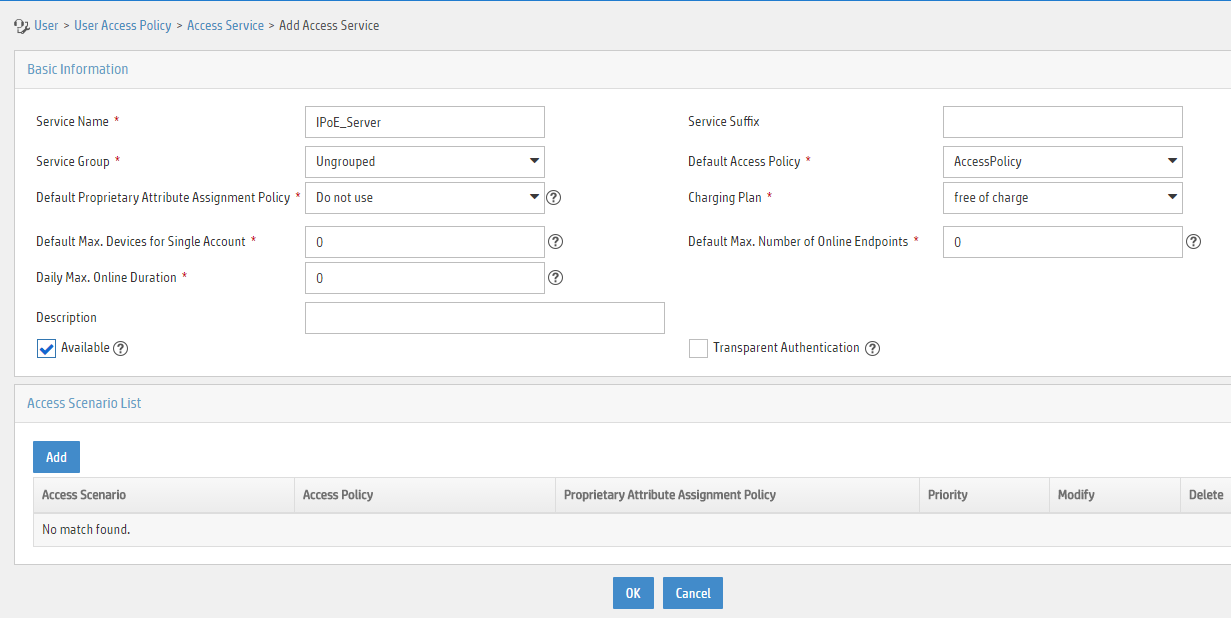
a. Add a user:
- Select User Management > Add User from the navigation tree to open the adding user page, as shown in Figure 134.
- Enter the username IPoE_Web001 and the user ID 001.
- Click OK.
Figure 150 Adding a user

a. Add an access user:
- Select Access User > All Access Users from the navigation tree to open the access user page.
- Click Add to open the page as shown in Figure 135.
- Select IPoE_Web001 for the username.
- Enter the account name user1.
- Enter the password pass1.
- Select the access service IPoE_Server.
Figure 151 Adding an access user

5. Configure the portal server:
a. Configure the portal homepage:
- Select User Access Policy > Portal Service > Server from the navigation tree to open the portal server configuration page, as shown in Figure 136.
- Click OK.
Figure 152 Portal server configuration page

a. Configure portal authentication source IP address range:
- Select User Access Policy > Portal Service > IP Group from the navigation tree to open the portal IP address group configuration page.
- Click Add to open the page as shown in Figure 137.
- Enter the IP group name IPoE_Web_User.
- Enter the start IP address (192.168.0.1) and end IP address (192.168.0.255) of the IP group. Make sure the host IP address is in the IP group.
- Click OK.
Figure 153 Adding an IP address group (IPv4)

- Select User Access Policy > Portal Service > IP Group from the navigation tree to open the portal IP address group configuration page.
- Click Add to open the page as shown in Figure 138.
- Enter the IP group name IPoE_Web_User-2.
- Select Yes from the IPv6 list.
- Enter the start IP address (192::1) and end IP address (192::FFFF) of the IP group. Make sure the host IPv6 address is in the IP group.
- Click OK.
Figure 154 Adding an IP address group (IPv6)

a. Add portal devices:
- Select User Access Policy > Portal Service > Device from the navigation tree to open the portal device configuration page.
- Click Add to open the page as shown in Figure 139.
- Enter the device name NAS.
- Enter the IP address of the portal packets' outgoing interface Ten-GigabitEthernet 3/1/2 (4.4.4.2).
- Enter the key 123456.
- Select Directly Connect for the access method.
- Click OK.
Figure 155 Adding a portal device (IPv4)

- Select User Access Policy > Portal Service > Device from the navigation tree to open the portal device configuration page.
- Click Add to open the page as shown in Figure 140.
- Enter the device name NAS-2.
- Select Portal 3.0 from the Version list.
- Enter the IP address of the portal packets' outgoing interface Ten-GigabitEthernet 3/1/2 (4::2).
- Enter the key 123456.
- Select Directly Connect for access method.
- Click OK.
Figure 156 Adding a portal device (IPv6)
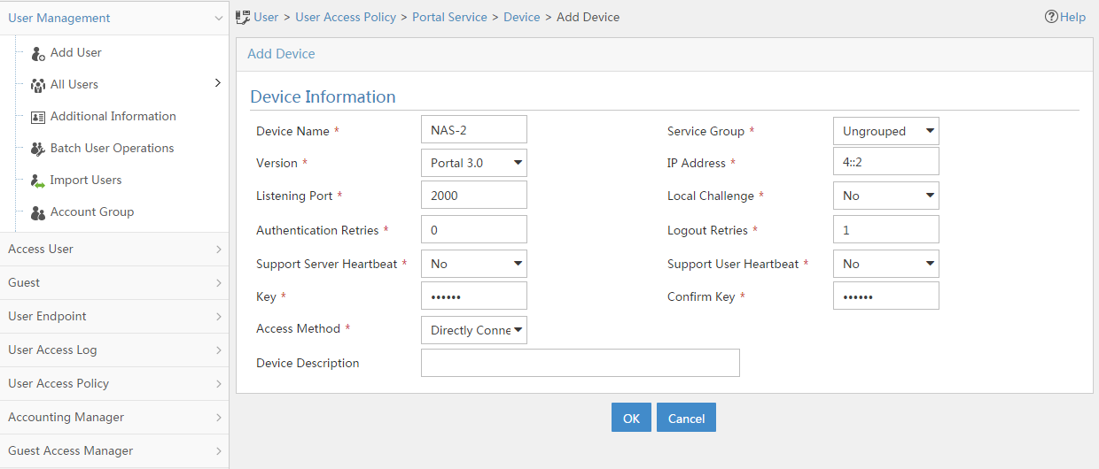
a. Associate the portal device with the IP address group:
- Select User Access Policy > Portal Service > Device from the navigation tree to open the portal device configuration page.
- Click the icon in the Port Group Information Management column of device NAS to open the port group configuration page, as shown in Figure 141.
- Click Add to open the page as shown in Figure 142.
- Enter the port group name group.
- Select the configured IP address group IPoE_Web_User. Make sure the IP address used by the user to access the network is within this IP address group.
- Click OK.
Figure 157 Device list

Figure 158 Port group configuration (IPv4)

- Select User Access Policy > Portal Service > Device from the navigation tree to open the portal device configuration page.
- Click the icon in the Port Group Information Management column of device NAS-2 to open the port group configuration page, as shown in Figure 141.
- Click Add to open the page as shown in Figure 143.
- Enter the port group name group-2.
- Select the configured IP address group IPoE_Web_User-2. Make sure the IPv6 address used by the user to access the network is within this IPv6 address group.
- Click OK.
Figure 159 Port group configuration (IPv6)

Verifying the configuration
# Display IPoE session information to verify that the host has passed preauthentication and obtained IPv4 address 192.168.0.2 and no IPv6 address.
[Device] display access-user auth-type pre-auth
UserID Interface IP address MAC address S-/C-VLAN
Username IPv6 address Access type
0x33d XGE3/1/2 192.168.0.2 0015-e947-f4d4 -/-
0015e947f4d4 - L2 IPoE dynamic
As shown in Figure 144, the Web login page opens after preauthentication. Enter the username and password on the page.
Figure 160 Web login page
# Display IPoE session information to verify that the host has passed Web authentication and come online in the IPv4 protocol stack.
[Device] display access-user auth-type pre-auth
UserID Interface IP address MAC address S-/C-VLAN
Username IPv6 address Access type
0x33d XGE3/1/2 192.168.0.2 0015-e947-f4d4 -/-
user1@dm2 - Web auth
# When the device receives DHCPv6 packets, display IPoE session information to verify that the host has come online in the IPv6 protocol stack.
[Device] display access-user auth-type web-auth
UserID Interface IP address MAC address S-/C-VLAN
Username IPv6 address Access type
0x33d XGE3/1/2 192.168.0.2 0015-e947-f4d4 -/-
user1@dm2 192::2 Web auth
# Click Log Out. The user returns from the Web authentication phase to the preauthentication phase. Display IPoE session information to verify that the host has been logged out in the IPv6 protocol stack.
[Device] display access-user auth-type pre-auth
UserID Interface IP address MAC address S-/C-VLAN
Username IPv6 address Access type
0x33d XGE3/1/2 192.168.0.2 0015-e947-f4d4 -/-
0015e947f4d4 - L2 IPoE dynamic
Example: Configuring IPoE common transparent MAC authentication for dual-stack users
Network configuration
As shown in Figure 161, the host accesses the BRAS as a DHCP client though a Layer 2 device. It obtains configuration information from the DHCP server through the BRAS. The BRAS performs AAA for the host through the RADIUS server. A server installed with H3C IMC acts as the portal authentication server and the portal Web server. This example uses IMC PLAT 7.1(E0303), IMC UAM 7.1(E0305), and IMC EIP 7.1(E0305). A RADIUS server that supports MAC binding acts as the authentication, authorization, and accounting server and performs MAC binding. The FTP server is an internal network server. Limit the access rate to 5 Mbps for the user after passing Web authentication.
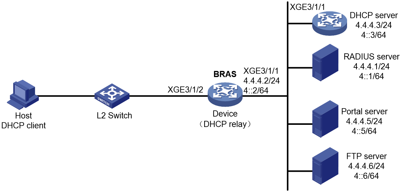
Prerequisites
Configure IP addresses for interfaces, and make sure devices can reach each other at Layer 3. (Details not shown.)
Configure the DNS server properly, so that the server can parse the IPv4 URL or IPv6 URL corresponding to the Web authentication page http://www.ipv4.web.com or http://www.ipv6.web.com according to the first protocol stack that comes online of the IPoE dual-stack user. (Details not shown.)
Procedure
1. Configure the DHCP servers:
a. Configure an IP address pool:
# Enable DHCP.
<DHCP-server> system-view
[DHCP-server] dhcp enable
# Enable the DHCP server to return a DHCP-NAK message if the client notions of their IP addresses are incorrect.
[DHCP-server] dhcp server request-ip-address check
# Create an IP address pool named pool1 and enter its view.
[DHCP-server] ip pool pool1
# Specify primary subnet 192.168.0.0/24 for dynamic allocation and DNS server 8.8.8.8 in address pool pool1.
[DHCP-server-ip-pool-pool1] network 192.168.0.0 24
[DHCP-server-ip-pool-pool1] dns-list 8.8.8.8
# Specify gateway address 192.168.0.1 in address pool pool1.
[DHCP-server-ip-pool-pool1] gateway-list 192.168.0.1
# Exclude IP address 192.168.0.1 from dynamic allocation in address pool pool1.
[DHCP-server-ip-pool-pool1] forbidden-ip 192.168.0.1
[DHCP-server-ip-pool-pool1] quit
# Configure the default route.
[DHCP-server] ip route-static 0.0.0.0 0 4.4.4.2
b. Configure an IPv6 address pool:
# Create an IPv6 address pool named pool2 and enter its view.
[DHCP-server] ipv6 pool pool2
# Specify primary subnet 192::/64 for dynamic allocation and DNS server 8::8 in address pool pool2.
[DHCP-server-ipv6-pool-pool2] network 192::/64
[DHCP-server-ipv6-pool-pool2] dns-server 8::8
[DHCP-server-ipv6-pool-pool2] quit
# Exclude IP address 192::1 from dynamic allocation in address pool pool2.
[DHCP-server] ipv6 dhcp server forbidden-address 192::1
# Enable the DHCPv6 server on Ten-GigabitEthernet 3/1/1.
[DHCP-server] interface ten-gigabitethernet 3/1/1
[DHCP-server-Ten-GigabitEthernet3/1/1] ipv6 dhcp select server
[DHCP-server-Ten-GigabitEthernet3/1/1] quit
# Configure the default route.
[DHCP-server] ipv6 route-static :: 0 4::2
2. Configure the BRAS:
a. Configure the DHCP relay agent:
# Enable DHCP.
<Device> system-view
[Device] dhcp enable
# Create a remote BAS IP address pool named pool1.
[Device] ip pool pool1 bas remote
# Specify the gateway address in address pool pool1.
[Device-ip-pool-pool1] gateway 192.168.0.1 24
# Exclude IP address 192.168.0.1 from dynamic allocation in address pool pool1.
[Device-ip-pool-pool1] forbidden-ip 192.168.0.1
# Specify DHCP server 4.4.4.3 in address pool pool1.
[Device-ip-pool-pool1] remote-server 4.4.4.3
[Device-ip-pool-pool1] quit
# Create a remote IPv6 address pool named pool2.
[Device] ipv6 pool pool2
# Specify gateway address 192::1 in address pool pool2.
[Device-ipv6-pool-pool2] gateway-list 192::1
# Specify IPv6 subnet 192::/64 in address pool pool2.
[Device-ipv6-pool-pool2] network 192::/64 export-route
# Specify DHCP server 4::3 in address pool pool2.
[Device-ipv6-pool-pool2] remote-server 4::3
[Device-ipv6-pool-pool2] quit
# Enable the DHCPv4 relay agent on Ten-GigabitEthernet 3/1/2.
[Device] interface ten-gigabitethernet 3/1/2
[Device–Ten-GigabitEthernet3/1/2] dhcp select relay
# Automatically generate a link-local address for Ten-GigabitEthernet 3/1/2.
[Device–Ten-GigabitEthernet3/1/2] ipv6 address auto link-local
# Enable the DHCPv6 relay agent on Ten-GigabitEthernet 3/1/2.
[Device–Ten-GigabitEthernet3/1/2] ipv6 dhcp select relay
# Disable RA message suppression on Ten-GigabitEthernet 3/1/2.
[Device–Ten-GigabitEthernet3/1/2] undo ipv6 nd ra halt
# Set the managed address configuration flag (M) to 1 in RA advertisements to be sent. Then, the host uses a DHCPv6 server to obtain IPv6 addresses.
[Device–Ten-GigabitEthernet3/1/2] ipv6 nd autoconfig managed-address-flag
# Set the other stateful configuration flag (O) to 1 in RA advertisements to be sent. Then, the host uses a DHCPv6 server to obtain configuration information other than IPv6 addresses.
[Device–Ten-GigabitEthernet3/1/2] ipv6 nd autoconfig other-flag
# Disable Ten-GigabitEthernet 3/1/2 from advertising the specified prefix in RA messages, preventing the endpoint from obtaining a temporary IPv6 address. In an IPv6 network, an endpoint might use a temporary IPv6 address for IPoE Web authentication, which will cause authentication failure.
[Device–Ten-GigabitEthernet3/1/2] ipv6 nd ra prefix 192::/64 no-advertise
[Device–Ten-GigabitEthernet3/1/2] quit
b. Configure the portal servers:
# Configure the IP address of the IPv4 portal authentication server newpt1 as 4.4.4.5 and the plaintext key 123456.
[Device] portal server newpt1
[Device-portal-server-newpt1] ip 4.4.4.5 key simple 123456
[Device-portal-server-newpt1] quit
# Configure the IPv6 address of the IPv6 portal authentication server newpt2 as 4::5 and the plaintext key 123456.
[Device] portal server newpt2
[Device-portal-server-newpt2] ipv6 4::5 key simple 123456
[Device-portal-server-newpt2] quit
c. Specify 11111 as the HTTPS redirect listening port number. Make sure the port number is not used by any other service. To see the TCP port numbers used by other services, execute the display tcp command.
[Device] http-redirect https-port 11111
d. Configure the device to get user access information from ARP and ND entries.
[Device] portal access-info trust arp
[Device] portal access-info trust nd
e. Create a local user group named pre.
[Device] user-group pre
New user group added.
[Device-ugroup-pre] quit
f. Configure ACLs for preauthentication:
# Create an IPv4 and IPv6 advanced ACL named web_permit separately. Configure a rule to permit all packets destined for the portal server from users in user group pre.
[Device] acl advanced name web_permit
[Device-acl-ipv4-adv-web_permit] rule 0 permit ip destination 4.4.4.5 0 user-group pre
[Device-acl-ipv4-adv-web_permit] quit
[Device] acl ipv6 advanced name web_permit
[Device-acl-ipv6-adv-web_permit] rule 0 permit ipv6 destination 4::5 128 user-group pre
[Device-acl-ipv6-adv-web_permit] quit
# Create an IPv4 and IPv6 advanced ACL named neiwang separately. Configure a rule to permit all packets destined for the internal network server from users in user group pre.
[Device] acl advanced name neiwang
[Device-acl-ipv4-adv-neiwang] rule 0 permit ip destination 4.4.4.6 0 user-group pre
[Device-acl-ipv4-adv-neiwang] quit
[Device] acl ipv6 advanced name neiwang
[Device-acl-ipv6-adv-neiwang] rule 0 permit ipv6 destination 4::6 128 user-group pre
[Device-acl-ipv6-adv-neiwang] quit
# Create an IPv4 and IPv6 advanced ACL named web_http separately. Configure a rule to permit TCP packets with the destination port 80 (HTTP packets) from users in user group pre.
[Device] acl advanced name web_http
[Device-acl-ipv4-adv-web_http] rule 0 permit tcp destination-port eq www user-group pre
[Device-acl-ipv4-adv-web_http] quit
[Device] acl ipv6 advanced name web_http
[Device-acl-ipv6-adv-web_http] rule 0 permit tcp destination-port eq www user-group pre
[Device-acl-ipv6-adv-web_http] quit
# Create an IPv4 and IPv6 advanced ACL named web_https separately, and configure a rule to permit TCP packets with the destination port 443 (HTTPS packets) from users in user group pre.
[Device] acl advanced name web_https
[Device-acl-ipv4-adv-web_https] rule 0 permit tcp destination-port eq 443 user-group pre
[Device-acl-ipv4-adv-web_https] quit
[Device] acl ipv6 advanced name web_https
[Device-acl-ipv6-adv-web_https] rule 0 permit tcp destination-port eq 443 user-group pre
[Device-acl-ipv6-adv-web_https] quit
# Create an IPv4 and IPv6 advanced ACL named ip separately, and configure a rule to permit IP packets from users in user group pre.
[Device] acl advanced name ip
[Device-acl-ipv4-adv-ip] rule 0 permit ip user-group pre
[Device-acl-ipv4-adv-ip] quit
[Device] acl ipv6 advanced name ip
[Device-acl-ipv6-adv-ip] rule 0 permit ipv6 user-group pre
[Device-acl-ipv6-adv-ip] quit
# Create an IPv4 and IPv6 advanced ACL named neiwang_out separately, and configure a rule to permit IP packets from the internal network server in user group pre.
[Device] acl advanced name neiwang_out
[Device-acl-ipv4-adv-neiwang_out] rule 0 permit ip source 4.4.4.6 0 user-group pre
[Device-acl-ipv4-adv-neiwang_out] quit
[Device] acl ipv6 advanced name neiwang_out
[Device-acl-ipv6-adv-neiwang_out] rule 0 permit ipv6 source 4::6 128 user-group pre
[Device-acl-ipv6-adv-neiwang_out] quit
# Create an IPv4 and IPv6 advanced ACL named web_out separately, and configure a rule to permit IP packets from the portal server in user group pre.
[Device] acl advanced name web_out
[Device-acl-ipv4-adv-web_out] rule 0 permit ip source 4.4.4.5 0 user-group pre
[Device-acl-ipv4-adv-web_out] quit
[Device] acl ipv6 advanced name web_out
[Device-acl-ipv6-adv-web_out] rule 0 permit ipv6 source 4::5 128 user-group pre
[Device-acl-ipv6-adv-web_out] quit
g. Configure QoS traffic classes for preauthentication users:
# Create the traffic class web_permit and specify ACL web_permit as the match criterion.
[Device] traffic classifier web_permit operator or
[Device-classifier-web_permit] if-match acl name web_permit
[Device-classifier-web_permit] if-match acl ipv6 name web_permit
[Device-classifier-web_permit] quit
# Create the traffic class neiwang and specify ACL neiwang as the match criterion.
[Device] traffic classifier neiwang operator or
[Device-classifier-neiwang] if-match acl name neiwang
[Device-classifier-neiwang] if-match acl ipv6 name neiwang
[Device-classifier-neiwang] quit
# Create the traffic class web_http and specify ACL web_http as the match criterion.
[Device] traffic classifier web_http operator or
[Device-classifier-web_http] if-match acl name web_http
[Device-classifier-web_http] if-match acl ipv6 name web_http
[Device-classifier-web_http] quit
# Create the traffic class web_https and specify ACL web_https as the match criterion.
[Device] traffic classifier web_https operator or
[Device-classifier-web_https] if-match acl name web_https
[Device-classifier-web_https] if-match acl ipv6 name web_https
[Device-classifier-web_https] quit
# Create the traffic class ip_cpu and specify ACL ip as the match criterion.
[Device] traffic classifier ip_cpu operator or
[Device-classifier-ip_cpu] if-match acl name ip
[Device-classifier-ip_cpu] if-match acl ipv6 name ip
[Device-classifier-ip_cpu] quit
# Create the traffic class ip_deny and specify ACL ip as the match criterion.
[Device] traffic classifier ip_deny operator or
[Device-classifier-ip_deny] if-match acl name ip
[Device-classifier-ip_deny] if-match acl ipv6 name ip
[Device-classifier-ip_deny] quit
# Create the traffic class neiwang_out and specify ACL neiwang_out as the match criterion.
[Device] traffic classifier neiwang_out operator or
[Device-classifier-neiwang_out] if-match acl name neiwang_out
[Device-classifier-neiwang_out] if-match acl ipv6 name neiwang_out
[Device-classifier-neiwang_out] quit
# Create the traffic class web_out and specify ACL web_out as the match criterion.
[Device] traffic classifier web_out operator or
[Device-classifier-web_out] if-match acl name web_out
[Device-classifier-web_out] if-match acl ipv6 name web_out
[Device-classifier-web_out] quit
h. Configure QoS traffic behaviors:
# Configure the traffic behavior web_permit to permit traffic to pass through without rate limiting or accounting.
[Device] traffic behavior web_permit
[Device-behavior-web_permit] filter permit
[Device-behavior-web_permit] free account
[Device-behavior-web_permit] quit
# Configure the traffic behavior neiwang to permit traffic to pass through.
[Device] traffic behavior neiwang
[Device-behavior-neiwang] filter permit
[Device-behavior-neiwang] quit
# Configure the traffic behavior web_http to redirect HTTP packets to the CPU.
[Device] traffic behavior web_http
[Device-behavior-web_http] redirect http-to-cpu
[Device-behavior-web_http] quit
# Configure the traffic behavior web_https to redirect HTTPS packets to the CPU.
[Device] traffic behavior web_https
[Device-behavior-web_https] redirect https-to-cpu
[Device-behavior-web_https] quit
# Configure the traffic behavior web_cpu to redirect IP packets to the CPU.
[Device] traffic behavior web_cpu
[Device-behavior-web_cpu] redirect cpu
[Device-behavior-web_cpu] quit
# Configure the traffic behavior web_deny to deny traffic.
[Device] traffic behavior web_deny
[Device-behavior-web_deny] filter deny
[Device-behavior-web_deny] free account
[Device-behavior-web_deny] quit
# Configure the traffic behavior neiwang_out to permit traffic to pass through.
[Device] traffic behavior neiwang_out
[Device-behavior-neiwang_out] filter permit
[Device-behavior-neiwang_out] quit
# Configure the traffic behavior web_out to permit traffic without rate limiting or traffic accounting.
[Device] traffic behavior web_out
[Device-behavior-web_out] filter permit
[Device-behavior-web_out] free account
[Device-behavior-web_out] quit
i. Configure the QoS policies:
# Create a QoS policy named web.
[Device] qos policy web
# Associate the traffic class web_permit with the traffic behavior web_permit.
[Device-qospolicy-web] classifier web_permit behavior web_permit
# Associate the traffic class neiwang with the traffic behavior neiwang.
[Device-qospolicy-web] classifier neiwang behavior neiwang
# Associate the traffic class web_http with the traffic behavior web_http.
[Device-qospolicy-web] classifier web_http behavior web_http
# Associate the traffic class web_https with the traffic behavior web_https.
[Device-qospolicy-web] classifier web_https behavior web_https
# Associate the traffic class ip_cpu with the traffic behavior web_cpu.
[Device-qospolicy-web] classifier ip_cpu behavior web_cpu
# Associate the traffic class ip_deny with the traffic behavior web_deny.
[Device-qospolicy-web] classifier ip_deny behavior web_deny
[Device-qospolicy-web] quit
# Configure a QoS policy named out.
[Device] qos policy out
# Associate the traffic class web_out with the traffic behavior web_out. Associate the traffic class neiwang_out with the traffic behavior neiwang_out. Associate the traffic class web_deny with the traffic behavior web_deny.
[Device-qospolicy-out] classifier web_out behavior web_out
[Device-qospolicy-out] classifier neiwang_out behavior neiwang_out
[Device-qospolicy-out] classifier ip_deny behavior web_deny
[Device-qospolicy-out] quit
j. Apply the QoS policies:
# Apply the QoS Policy web to the inbound traffic globally. To identify whether the QoS policy takes effect, execute the display qos policy global inbound command.
[Device] qos apply policy web global inbound
# Apply the QoS Policy out to the outbound traffic globally. To identify whether the QoS policy takes effect, execute the display qos policy global outbound command.
[Device] qos apply policy out global outbound
k. Configure a RADIUS scheme:
# Create a RADIUS scheme named rs1 and enter its view.
[Device] radius scheme rs1
# Configure primary servers and keys for authentication and accounting.
[Device-radius-rs1] primary authentication 4.4.4.1
[Device-radius-rs1] primary accounting 4.4.4.1
[Device-radius-rs1] key authentication simple radius
[Device-radius-rs1] key accounting simple radius
# Exclude the ISP name from the username sent to the RADIUS server.
[Device-radius-rs1] user-name-format without-domain
[Device-radius-rs1] quit
# (Optional.) Enable RADIUS session control. As a best practice, configure this feature when an IMC server acts as the RADIUS server.
[Device] radius session-control enable
# Set the IP address of the RADIUS DAE client to 4.4.4.1, and set the shared key to radius for the RADIUS DAE client to exchange DAE packets.
[Device] radius dynamic-author server
[Device-radius-da-server] client ip 4.4.4.1 key simple radius
[Device-radius-da-server] quit
l. Configure the preauthentication ISP domain and Web authentication ISP domain:
# Configure the ISP domain dm1 for IPoE user preauthentication.
[Device] domain name dm1
[Device-isp-dm1] authentication ipoe none
[Device-isp-dm1] authorization ipoe none
[Device-isp-dm1] accounting ipoe none
# Configure the authorized user group and IP address pools in preauthentication ISP domain dm1.
[Device-isp-dm1] authorization-attribute user-group pre
[Device-isp-dm1] authorization-attribute ip-pool pool1
[Device-isp-dm1] authorization-attribute ipv6-pool pool2
# Configure the Web authentication page URL in ISP domain dm1.
[Device-isp-dm1] web-server url http://www.ipv4.web.com
[Device-isp-dm1] web-server ipv6-url http://www.ipv6.web.com
[Device-isp-dm1] quit
# Configure the ISP domain dm2 for IPoE user Web authentication.
[Device] domain name dm2
[Device-isp-dm2] authentication ipoe radius-scheme rs1
[Device-isp-dm2] authorization ipoe radius-scheme rs1
[Device-isp-dm2] accounting ipoe radius-scheme rs1
[Device-isp-dm2] authorization-attribute car inbound cir 5120 outbound cir 5120
[Device-isp-dm2] quit
m. Configure IPoE:
# Enable IPoE and configure Layer 2 access mode on Ten-GigabitEthernet 3/1/2.
[Device] interface ten-gigabitethernet 3/1/2
[Device–Ten-GigabitEthernet3/1/2] ip subscriber l2-connected enable
# Configure Web MAC authentication for IPoE users on Ten-GigabitEthernet 3/1/2.
[Device–Ten-GigabitEthernet3/1/2] ip subscriber authentication-method web mac-auth
The operation may cut all users on this interface. Continue?[Y/N]:y
# Configure the ISP domain dm1 for preauthentication and the ISP domain dm2 for Web authentication and Web MAC authentication on Ten-GigabitEthernet 3/1/2.
[Device–Ten-GigabitEthernet3/1/2] ip subscriber pre-auth domain dm1
[Device–Ten-GigabitEthernet3/1/2] ip subscriber web-auth domain dm2
[Device–Ten-GigabitEthernet3/1/2] ip subscriber mac-auth domain dm2
[Device–Ten-GigabitEthernet3/1/2] quit
3. Configure the RADIUS server.
For how to configure AAA and MAC binding on the RADIUS server, see the RADIUS server configuration guide.
4. Configure the portal server:
a. Configure the portal homepage:
- Select User Access Policy > Portal Service > Server from the navigation tree to open the portal server configuration page, as shown in Figure 162.
- Click OK.
Figure 162 Portal server configuration page

a. Configure portal authentication source IP address range:
- Select User Access Policy > Portal Service > IP Group from the navigation tree to open the portal IP address group configuration page.
- Click Add to open the page as shown in Figure 163.
- Enter the IP group name IPoE_Web_User.
- Enter the start IP address (192.168.0.1) and end IP address (192.168.0.255) of the IP group. Make sure the host IP address is in the IP group.
- Click OK.
Figure 163 Adding an IP address group (IPv4)
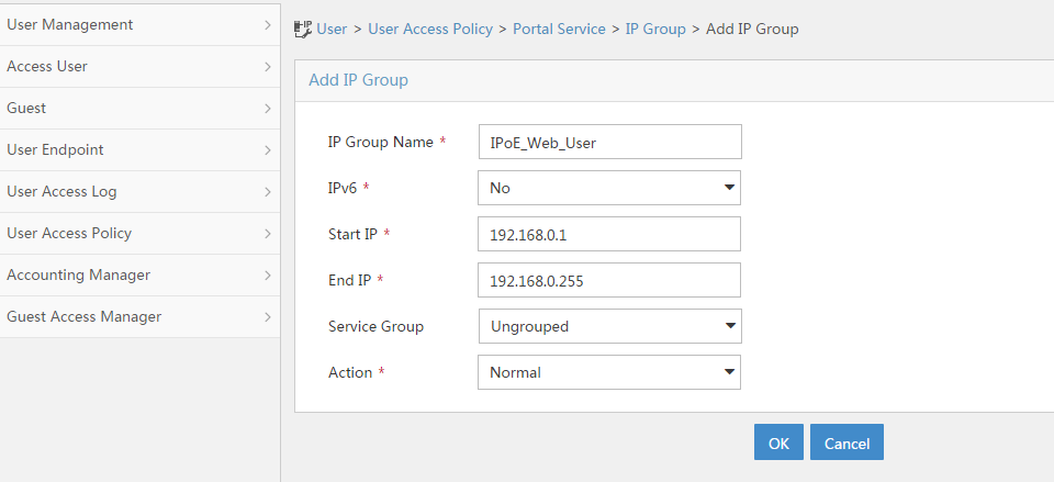
- Select User Access Policy > Portal Service > IP Group from the navigation tree to open the portal IP address group configuration page.
- Click Add to open the page as shown in Figure 164.
- Enter the IP group name IPoE_Web_User-2.
- Select Yes from the IPv6 list.
- Enter the start IP address (192::1) and end IP address (192::FFFF) of the IP group. Make sure the host IPv6 address is in the IP group.
- Click OK.
Figure 164 Adding an IP address group (IPv6)

a. Add a portal device:
- Select User Access Policy > Portal Service > Device from the navigation tree to open the portal device configuration page.
- Click Add to open the page as shown in Figure 165.
- Enter the device name NAS.
- Enter the IP address of the portal packets' outgoing interface Ten-GigabitEthernet 3/1/1 (4.4.4.2).
- Enter the key 123456.
- Select Directly Connect for access method.
- Click OK.
Figure 165 Adding a portal device (IPv4)
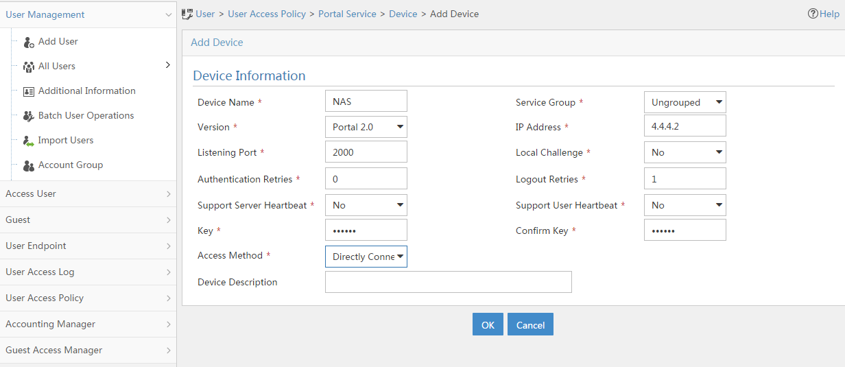
- Select User Access Policy > Portal Service > Device from the navigation tree to open the portal device configuration page.
- Click Add to open the page as shown in Figure 166.
- Enter the device name NAS-2.
- Select Portal 3.0 from the Version list.
- Enter the IP address of the portal packets' outgoing interface Ten-GigabitEthernet 3/1/1 (4::2).
- Enter the key 123456.
- Select Directly Connect for access method.
- Click OK.
Figure 166 Adding a portal device (IPv6)

a. Associate the portal device with the IP address group:
- Select User Access Policy > Portal Service > Device from the navigation tree to open the portal device configuration page.
- Click the icon in the Port Group Information Management column of device NAS to open the port group configuration page, as shown in Figure 167.
- Click Add to open the page as shown in Figure 168.
- Enter the port group name group.
- Select the configured IP address group IPoE_Web_User. Make sure the IP address used by the user to access the network is within this IP address group.
- Click OK.

Figure 168 Port group configuration (IPv4)

- Select User Access Policy > Portal Service > Device from the navigation tree to open the portal device configuration page.
- Click the icon in the Port Group Information Management column of device NAS-2 to open the port group configuration page, as shown in Figure 167.
- Click Add to open the page as shown in Figure 169.
- Enter the port group name group-2.
- Select the configured IP address group IPoE_Web_User-2. Make sure the IPv6 address used by the user to access the network is within this IPv6 address group.
- Click OK.
Figure 169 Port group configuration (IPv6)

a. From the navigation tree, select User Access Manager > Service Parameters > Validate System Configuration to validate the settings.
Verifying the configuration
# Display IPoE session information to verify that the host has passed preauthentication and obtained IPv4 address 192.168.0.2 and IPv6 address 192::2.
[Device] display access-user auth-type pre-auth
UserID Interface IP address MAC address S-/C-VLAN
Username IPv6 address Access type
0x33d XGE3/1/2 192.168.0.2 0015-e947-f4d4 -/-
0015e947f4d4 192::2 L2 IPoE dynamic
As shown in Figure 170, the Web login page opens after preauthentication. Enter the username and password on the page.
# Display IPoE session information to verify that the host has passed Web authentication and come online.
[Device] display access-user auth-type web-auth
UserID Interface IP address MAC address S-/C-VLAN
Username IPv6 address Access type
0x33d XGE3/1/2 192.168.0.2 0015-e947-f4d4 -/-
user1@dm2 192::2 Web auth
# Click Log Out on the Web login page as shown in Figure 170.
# Verify that the user returns to the preauthentication status.
[Device] display access-user auth-type pre-auth
UserID Interface IP address MAC address S-/C-VLAN
Username IPv6 address Access type
0x33d XGE3/1/2 192.168.0.2 0015-e947-f4d4 -/-
0015e947f4d4 192::2 L2 IPoE dynamic
# Open the browser, and enter an address randomly, for example, http://63.1.1.240.
# Verify that the user has come online through IPoE Web MAC authentication.
[Device] display access-user auth-type web-auth
UserID Interface IP address MAC address S-/C-VLAN
Username IPv6 address Access type
0x33d XGE3/1/2 192.168.0.2 0015-e947-f4d4 -/-
0015e947f4d4 192::2 Web auth
Example: Configuring a dual-stack DHCP user
Network configuration
As shown in Figure 171, the host accesses the BRAS as a dual-stack user. The host obtains IPv4 and IPv6 addresses from the DHCP server. The BRAS performs AAA for the host through the RADIUS server. This example uses the Linux Free RADIUS server.

Prerequisites
Configure IP addresses for interfaces, and make sure devices can reach each other at Layer 3. (Details not shown.)
Procedure
1. Configure the RADIUS server:
# Add BRAS IP address 4.4.4.2 and secret radius to the clients.conf file.
client 4.4.4.2/32 {
ipaddr = 4.4.4.2
netmask=32
secret=radius
}
# Add the username and password to the users user information file. The username is the host MAC address and the password is radius.
000c29a6b656 Cleartext-Password :="radius"
2. Configure the DHCP server:
a. Configure an IP address pool:
# Enable DHCP.
<DHCP-server> system-view
[DHCP-server] dhcp enable
# Enable the DHCP server to return a DHCP-NAK message if the client notions of their IP addresses are incorrect.
[DHCP-server] dhcp server request-ip-address check
# Create an IP address pool named pool1 and enter its view.
[DHCP-server] ip pool pool1
# Specify the subnet 3.3.3.0/24 for dynamic allocation and DNS server 8.8.8.8 in the pool.
[DHCP-server-ip-pool-pool1] network 3.3.3.0 24
[DHCP-server-ip-pool-pool1] dns-list 8.8.8.8
# Specify gateway address 3.3.3.1 in the address pool.
[DHCP-server-ip-pool-pool1] gateway-list 3.3.3.1
# Exclude IP address 3.3.3.1 from dynamic allocation in the pool.
[DHCP-server-ip-pool-pool1] forbidden-ip 3.3.3.1
[DHCP-server-ip-pool-pool1] quit
# Configure the default route.
[DHCP-server] ip route-static 0.0.0.0 0 4.4.4.2
b. Configure an IPv6 address pool:
# Create an IPv6 address pool named pool2 and enter its view.
[DHCP-server] ipv6 pool pool2
# Specify the subnet 3::/64 for dynamic allocation and DNS server 8::8 in the pool.
[DHCP-server-ipv6-pool-pool2] network 3::/64
[DHCP-server-ipv6-pool-pool2] dns-server 8::8
[DHCP-server-ipv6-pool-pool2] quit
# Exclude IPv6 address 3::1 from dynamic allocation in the pool.
[DHCP-server] ipv6 dhcp server forbidden-address 3::1
# Enable the DHCPv6 server on Ten-GigabitEthernet 3/1/1.
[DHCP-server] interface ten-gigabitethernet 3/1/1
[DHCP-server-Ten-GigabitEthernet3/1/1] ipv6 dhcp select server
[DHCP-server-Ten-GigabitEthernet3/1/1] quit
# Configure the default route.
[DHCP-server] ipv6 route-static :: 0 4::2
3. Configure the BRAS:
a. Configure the DHCP relay agent:
# Enable DHCP.
<Device> system-view
[Device] dhcp enable
# Create a remote BAS IP address pool pool1, specify a gateway address in the address pool, exclude IP address 3.3.3.1 from dynamic allocation in the address pool, and specify a DHCP server for the address pool.
[Device] ip pool pool1 bas remote
[Device-ip-pool-pool1] gateway 3.3.3.1 24
[Device-ip-pool-pool1] forbidden-ip 3.3.3.1
[Device-ip-pool-pool1] remote-server 4.4.4.3
[Device-ip-pool-pool1] quit
# Create a remote IPv6 address pool pool2, specify a gateway address in the address pool, specify IPv6 subnet 3::/64 in the address pool, and specify a DHCPv6 server for the address pool.
[Device] ipv6 pool pool2
[Device-ipv6-pool-pool2] gateway-list 3::1
[Device-ipv6-pool-pool2] network 3::/64 export-route
[Device-ipv6-pool-pool2] remote-server 4::3
[Device-ipv6-pool-pool2] quit
# Enable the DHCPv4 relay agent and DHCPv6 relay agent on Ten-GigabitEthernet 3/1/2.
[Device] interface ten-gigabitethernet 3/1/2
[Device–Ten-GigabitEthernet3/1/2] dhcp select relay
[Device–Ten-GigabitEthernet3/1/2] ipv6 dhcp select relay
# Automatically generate a link-local address for Ten-GigabitEthernet 3/1/2.
[Device–Ten-GigabitEthernet3/1/2] ipv6 address auto link-local
# Disable RA message suppression on Ten-GigabitEthernet 3/1/2.
[Device–Ten-GigabitEthernet3/1/2] undo ipv6 nd ra halt
# Set the managed address configuration flag (M) to 1 in RA advertisements to be sent. Then, the host uses a DHCPv6 server to obtain IPv6 addresses.
[Device–Ten-GigabitEthernet3/1/2] ipv6 nd autoconfig managed-address-flag
# Set the other stateful configuration flag (O) to 1 in RA advertisements to be sent. Then, the host uses a DHCPv6 server to obtain configuration information other than IPv6 addresses.
[Device–Ten-GigabitEthernet3/1/2] ipv6 nd autoconfig other-flag
[Device–Ten-GigabitEthernet3/1/2] quit
b. Configure a RADIUS scheme:
# Create a RADIUS scheme named rs1 and enter its view.
[Device] radius scheme rs1
# Configure primary servers and keys for authentication and accounting.
[Device-radius-rs1] primary authentication 4.4.4.1
[Device-radius-rs1] primary accounting 4.4.4.1
[Device-radius-rs1] key authentication simple radius
[Device-radius-rs1] key accounting simple radius
# Exclude the ISP name from the username sent to the RADIUS server.
[Device-radius-rs1] user-name-format without-domain
[Device-radius-rs1] quit
c. Configure the ISP domain:
# Create an ISP domain named dm1 and enter its view.
[Device] domain name dm1
# Configure ISP domain dm1 to use RADIUS scheme rs1 and assign address pools.
[Device-isp-dm1] authentication ipoe radius-scheme rs1
[Device-isp-dm1] authorization ipoe radius-scheme rs1
[Device-isp-dm1] accounting ipoe radius-scheme rs1
[Device-isp-dm1] authorization-attribute ip-pool pool1
[Device-isp-dm1] authorization-attribute ipv6-pool pool2
[Device-isp-dm1] quit
d. Configure IPoE:
# Enable IPoE and configure Layer 2 access mode on Ten-GigabitEthernet 3/1/2.
[Device] interface ten-gigabitethernet 3/1/2
[Device–Ten-GigabitEthernet3/1/2] ip subscriber l2-connected enable
# Specify dm1 as the ISP domain for DHCP users.
[Device–Ten-GigabitEthernet3/1/2] ip subscriber dhcp domain dm1
# Configure plaintext password radius for authentication.
[Device–Ten-GigabitEthernet3/1/2] ip subscriber password plaintext radius
[Device–Ten-GigabitEthernet3/1/2] quit
Verifying the configuration
# Display IPoE session information to verify that the host has come online.
[Device] display access-user interface ten-gigabitethernet 3/1/2
UserID Interface IP address MAC address S-/C-VLAN
Username IPv6 address Access type
0x2c2 XGE3/1/2 3.3.3.2 000c-29a6-b656 -/-
000c29a6b656 3::2 L2 IPoE dynamic
Example: Configuring a dynamic/static dual-stack user
Network configuration
As shown in Figure 172, the host accesses the BRAS as a dual-stack user. The host comes online as an IPv4 global static individual user and comes online as an IPv6 dynamic DHCP user. The IPv4 address of the host is 3.3.3.2. The host obtains IPv6 addresses from the DHCP server without carrying Option 60 in DHCP packets. The BRAS performs AAA for the host through the RADIUS server. This example uses the Linux Free RADIUS server.
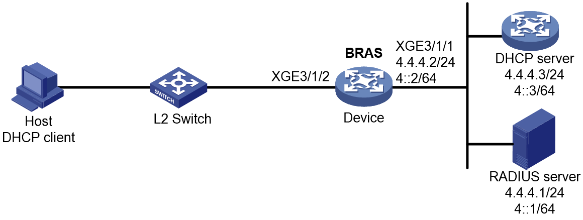
Prerequisites
Configure IP addresses for interfaces, and make sure devices can reach each other at Layer 3. (Details not shown.)
Procedure
1. Configure the RADIUS server:
# Add BRAS IP address 4.4.4.2 and secret radius to the clients.conf file.
client 4.4.4.2/32 {
ipaddr = 4.4.4.2
netmask=32
secret=radius
}
# Add the username and password to the users user information file. The username is the host MAC address and the password is radius.
000c29a6b656 Cleartext-Password :="radius"
2. Configure the DHCP server:
a. Configure an IPv6 address pool:
# Create an IPv6 address pool named pool1 and enter its view.
<DHCP-server> system-view
[DHCP-server] ipv6 pool pool1
# Specify the subnet 3::/64 for dynamic allocation and DNS sever 8::8 in the pool.
[DHCP-server-ipv6-pool-pool1] network 3::/64
[DHCP-server-ipv6-pool-pool1] dns-server 8::8
[DHCP-server-ipv6-pool-pool1] quit
# Exclude IPv6 address 3::1 from dynamic allocation in the pool.
[DHCP-server] ipv6 dhcp server forbidden-address 3::1
# Enable the DHCPv6 server on Ten-GigabitEthernet 3/1/1.
[DHCP-server] interface ten-gigabitethernet 3/1/1
[DHCP-server-Ten-GigabitEthernet3/1/1] ipv6 dhcp select server
[DHCP-server-Ten-GigabitEthernet3/1/1] quit
# Configure the default route.
[DHCP-server] ipv6 route-static :: 0 4::2
3. Configure the BRAS:
a. Configure the DHCP relay agent:
# Create a remote IPv6 address pool pool1, specify a gateway address in the address pool, specify IPv6 subnet 3::/64 in the address pool, and specify a DHCPv6 server for the address pool.
[Device] ipv6 pool pool1
[Device-ipv6-pool-pool1] gateway-list 3::1
[Device-ipv6-pool-pool1] network 3::/64 export-route
[Device-ipv6-pool-pool1] remote-server 4::3
[Device-ipv6-pool-pool1] quit
# Enable the DHCPv6 relay agent on Ten-GigabitEthernet 3/1/2.
[Device] interface ten-gigabitethernet 3/1/2
[Device–Ten-GigabitEthernet3/1/2] ipv6 dhcp select relay
# Automatically generate a link-local address for Ten-GigabitEthernet 3/1/2.
[Device–Ten-GigabitEthernet3/1/2] ipv6 address auto link-local
# Disable RA message suppression on Ten-GigabitEthernet 3/1/2.
[Device–Ten-GigabitEthernet3/1/2] undo ipv6 nd ra halt
# Set the managed address configuration flag (M) to 1 in RA advertisements to be sent. Then, the host uses a DHCPv6 server to obtain IPv6 addresses.
[Device–Ten-GigabitEthernet3/1/2] ipv6 nd autoconfig managed-address-flag
# Set the other stateful configuration flag (O) to 1 in RA advertisements to be sent. Then, the host uses a DHCPv6 server to obtain configuration information other than IPv6 addresses.
[Device–Ten-GigabitEthernet3/1/2] ipv6 nd autoconfig other-flag
[Device–Ten-GigabitEthernet3/1/2] quit
b. Configure a RADIUS scheme:
# Create a RADIUS scheme named rs1 and enter its view.
[Device] radius scheme rs1
# Configure primary servers and keys for authentication and accounting.
[Device-radius-rs1] primary authentication 4.4.4.1
[Device-radius-rs1] primary accounting 4.4.4.1
[Device-radius-rs1] key authentication simple radius
[Device-radius-rs1] key accounting simple radius
# Exclude the ISP name from the username sent to the RADIUS server.
[Device-radius-rs1] user-name-format without-domain
[Device-radius-rs1] quit
c. Configure the ISP domain:
# Create an ISP domain named dm1 and enter its view.
[Device] domain name dm1
# Configure ISP domain dm1 to use RADIUS scheme rs1 and assign address pools.
[Device-isp-dm1] authentication ipoe radius-scheme rs1
[Device-isp-dm1] authorization ipoe radius-scheme rs1
[Device-isp-dm1] accounting ipoe radius-scheme rs1
[Device-isp-dm1] authorization-attribute ipv6-pool pool1
[Device-isp-dm1] quit
d. Configure the DHCP server:
# Enable DHCP.
[Device] dhcp enable
# Enable the DHCP server to return a DHCP-NAK message if the client notions of their IP addresses are incorrect.
[Device] dhcp server request-ip-address check
# Create a local BAS IP address pool named pool1 and enter its view.
[Device] ip pool pool1 bas local
# Specify gateway address 3.3.3.1 in address pool pool1.
[Device-ip-pool-pool1] gateway 3.3.3.1 24
# Exclude IP address 3.3.3.2 from dynamic allocation in address pool pool1.
[Device-ip-pool-pool1] forbidden-ip 3.3.3.2
[Device-ip-pool-pool1] quit
e. Configure IPoE:
# Configure a global IPv4 IPoE static individual session with the ISP domain dm1 and enable dual stack support.
[Device] ip subscriber session static ip 3.3.3.2 domain dm1 support-ds
# Enable IPoE and configure Layer 2 access mode on Ten-GigabitEthernet 3/1/2.
[Device] interface ten-gigabitethernet 3/1/2
[Device–Ten-GigabitEthernet3/1/2] ip subscriber l2-connected enable
# Specify dm1 as the ISP domain for DHCP users.
[Device–Ten-GigabitEthernet3/1/2] ip subscriber dhcp domain dm1
# Enable ARP packet initiation on Ten-GigabitEthernet 3/1/2.
[Device–Ten-GigabitEthernet3/1/2] ip subscriber initiator arp enable
# Use the MAC addresses of the global static individual user and the dynamic user as their respective usernames.
[Device–Ten-GigabitEthernet3/1/2] ip subscriber username mac-address
# Configure plaintext password radius for authentication.
[Device–Ten-GigabitEthernet3/1/2] ip subscriber password plaintext radius
[Device–Ten-GigabitEthernet3/1/2] quit
Verifying the configuration
# Display IPoE session information to verify that the host has come online.
[Device] display access-user interface ten-gigabitethernet 3/1/2
UserID Interface IP address MAC address S-/C-VLAN
Username IPv6 address Access type
0x2c2 XGE3/1/2 3.3.3.2 000c-29a6-b656 -/-
000c29a6b656 3::2 L2 IPoE dynamic
Example: Configuring an IPoE DHCPv4+IPv6 ND RS dual-stack roaming user
Network configuration
As shown in Figure 173, configure dual-stack users as follows:
· In the IPv4 protocol stack:
¡ A host comes online through DHCP packets and accesses the BRAS through a Layer 2 network in IPoE mode.
¡ A host obtains an IP address from the DHCP server.
· In the IPv6 protocol stack:
¡ A host comes online through IPv6 ND RS packets and accesses the BRAS through a Layer 2 network in IPoE mode.
¡ The BRAS can send IPv6 ND RA packets.
The host can roam between areas and still stay online. The BRAS performs AAA for the host through the RADIUS server. This example uses the Linux Free RADIUS server.
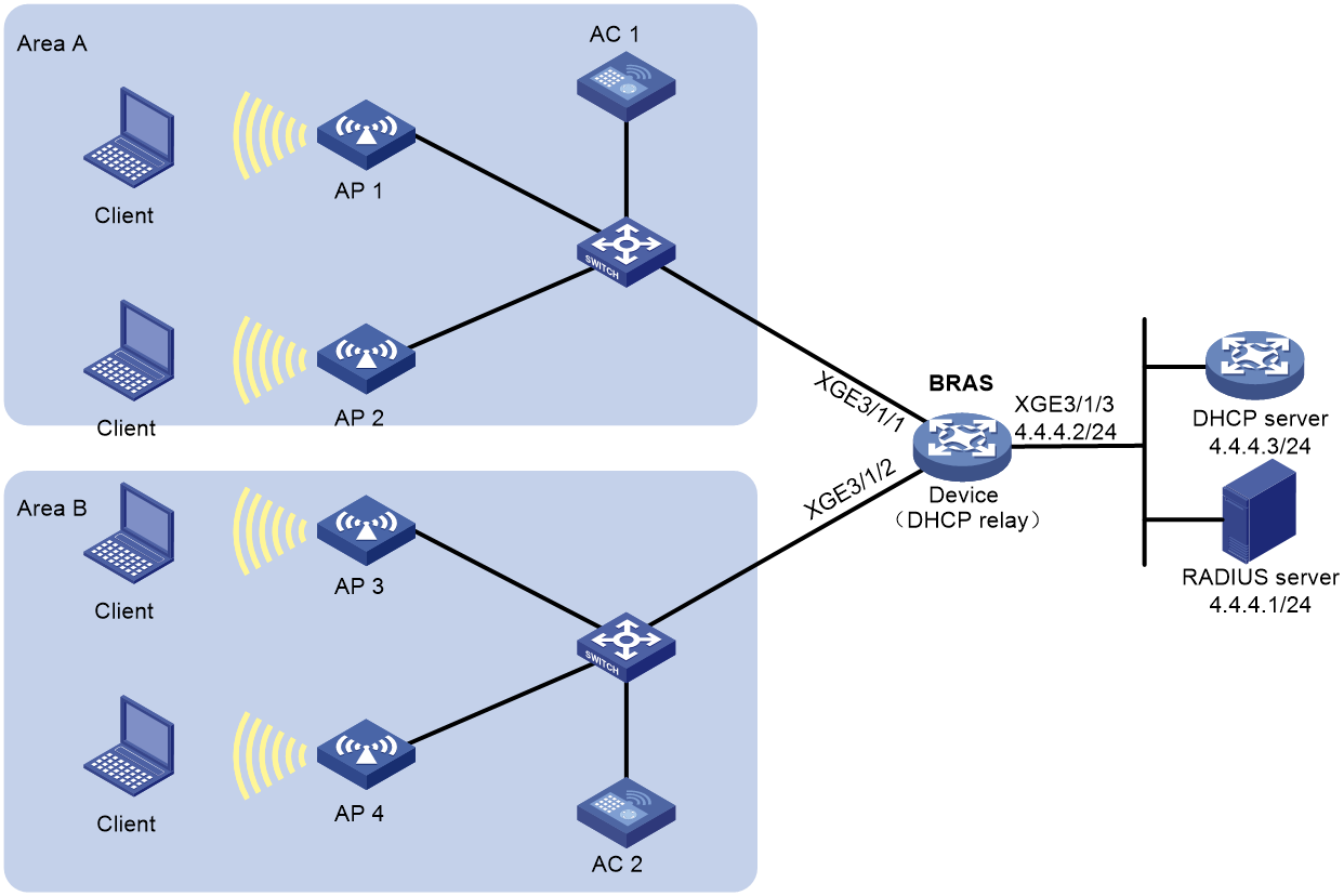
Prerequisites
Configure IP addresses for interfaces, and make sure devices can reach each other at Layer 3. (Details not shown.)
Procedure
1. Configure the RADIUS server:
# Add BRAS IP address 4.4.4.2 and secret radius to the clients.conf file.
client 4.4.4.2/32 {
ipaddr = 4.4.4.2
netmask=32
secret=radius
}
# Add the username and password to the users user information file. The username is the host MAC address, the password is radius, and the authorized IPv6 prefix is 10::10/64.
000c29a6b656 Cleartext-Password :="radius"
Framed-IPv6-Prefix =10::10/64
2. Configure the DHCP server:
a. Configure an IP address pool:
# Enable DHCP.
<DHCP-server> system-view
[DHCP-server] dhcp enable
# Enable the DHCP server to return a DHCP-NAK message if the client notions of their IP addresses are incorrect.
[DHCP-server] dhcp server request-ip-address check
# Create an IP address pool named pool1 and enter its view.
[DHCP-server] ip pool pool1
# Specify the subnet 3.3.3.0/24 for dynamic allocation in the pool.
[DHCP-server-ip-pool-pool1] network 3.3.3.0 24
# Specify gateway address 3.3.3.1 in the address pool.
[DHCP-server-ip-pool-pool1] gateway-list 3.3.3.1
# Exclude IP address 3.3.3.1 from dynamic allocation in the pool.
[DHCP-server-ip-pool-pool1] forbidden-ip 3.3.3.1
# Configure the DNS server address as 8.8.8.8.
[DHCP-server-ip-pool-pool1] dns-list 8.8.8.8
[DHCP-server-ip-pool-pool1] quit
# Configure the default route.
[DHCP-server] ip route-static 0.0.0.0 0 4.4.4.2
3. Configure the BRAS:
a. Configure a RADIUS scheme:
# Create a RADIUS scheme named rs1 and enter its view.
<Device> system-view
[Device] radius scheme rs1
# Configure primary servers and keys for authentication and accounting.
[Device-radius-rs1] primary authentication 4.4.4.1
[Device-radius-rs1] primary accounting 4.4.4.1
[Device-radius-rs1] key authentication simple radius
[Device-radius-rs1] key accounting simple radius
# Exclude the ISP name from the username sent to the RADIUS server.
[Device-radius-rs1] user-name-format without-domain
[Device-radius-rs1] quit
b. Configure the ISP domain:
# Create an ISP domain named dm1 and enter its view.
[Device] domain name dm1
# Configure dm1 to use RADIUS scheme rs1 and assign a remote BAS IP address pool.
[Device-isp-dm1] authentication ipoe radius-scheme rs1
[Device-isp-dm1] authorization ipoe radius-scheme rs1
[Device-isp-dm1] accounting ipoe radius-scheme rs1
[Device-isp-dm1] authorization-attribute ip-pool pool1
[Device-isp-dm1] quit
# Authorize an IPv6 DNS address pool to users.
[Device-isp-dm1] authorization-attribute primary-dns ipv6 8::8
c. Configure the DHCP relay agent:
# Enable DHCP.
[Device] dhcp enable
# Enable the DHCP server proxy on the relay agent on Ten-GigabitEthernet 3/1/1 and Ten-GigabitEthernet 3/1/2. (You can skip this step because this configuration exists by default.)
[Device] interface range ten-gigabitethernet 3/1/1 ten-gigabitethernet 3/1/2
[Device–if-range] dhcp-proxy enable
[Device–if-range] quit
# Assign addresses to roaming clients based on their existing address leases and renew the leases when the clients roam.
[Device–if-range] dhcp session-mismatch action roam
# Disable RA message suppression.
[Device–if-range] undo ipv6 nd ra halt
# Automatically generate link-local addresses.
[Device–if-range] ipv6 address auto link-local
# Create a remote BAS IP address pool pool1, specify a gateway address in the address pool, exclude IP address 3.3.3.1 from dynamic allocation in the address pool, and specify a DHCP server for the address pool.
[Device] ip pool pool1 bas remote
[Device-ip-pool-pool1] gateway 3.3.3.1 24
[Device-ip-pool-pool1] forbidden-ip 3.3.3.1
[Device-ip-pool-pool1] remote-server 4.4.4.3
[Device-ip-pool-pool1] quit
d. Configure IPoE:
# Enable IPoE and configure Layer 2 access mode on Ten-GigabitEthernet 3/1/1 and Ten-GigabitEthernet 3/1/2.
[Device] interface range ten-gigabitethernet 3/1/1 ten-gigabitethernet 3/1/2
[Device–if-range] ip subscriber l2-connected enable
# Enable IPv6 ND RS packet initiation.
[Device–if-range] ip subscriber initiator ndrs enable
# Enable ARP packet initiation.
[Device–if-range] ip subscriber initiator arp enable
# Enable NS/NA packet initiation.
[Device–if-range] ip subscriber initiator nsna enable
# Enable unclassified-IPv4 packet initiation and unclassified-IPv6 packet initiation.
[Device–if-range] ip subscriber initiator unclassified-ip enable matching-user
[Device–if-range] ip subscriber initiator unclassified-ipv6 enable matching-user
# Enabling roaming for IPoE individual users.
[Device–if-range] ip subscriber roaming enable
# Specify dm1 as the ISP domain for DHCP users.
[Device–if-range] ip subscriber dhcp domain dm1
# Specify dm1 as the ISP domain for IPv6 ND RS users.
[Device–if-range] ip subscriber dhcp domain dm1
# Configure plaintext password radius for authentication.
[Device–if-range] ip subscriber password plaintext radius
[Device–if-range] quit
Verifying the configuration
# Display IPoE session information to verify that the host in area A has come online.
[Device] display access-user interface ten-gigabitethernet 3/1/1
UserID Interface IP address MAC address S-/C-VLAN
Username IPv6 address Access type
0x5c XGE3/1/1 3.3.3.2 000c-29a6-b656 -/-
000c29a6b656 10::20C:29FF:FEA6:B6 L2 IPoE dynamic
56
# Display IPoE session information to verify that the user has roamed from area A to area B.
[Device] display access-user interface ten-gigabitethernet 3/1/2
UserID Interface IP address MAC address S-/C-VLAN
Username IPv6 address Access type
0x5c XGE3/1/2 3.3.3.2 000c-29a6-b656 -/-
000c29a6b656 10::20C:29FF:FEA6:B6 L2 IPoE dynamic
56
IPoE configuration examples(on CUPS network)
In a CUPS network, the CP and UP together act as a BRAS to provide BRAS services.
In a CUPS network, the device can act only as a UP, and cannot act as a CP.
The CP configuration procedures in this section are for reference only. For more information, see manuals for devices acting as CPs.
Example: Configuring unclassified-IP packet initiation
Network configuration
As shown in Figure 174, the host accesses the BRAS as an unclassified-IP user. The BRAS performs AAA for the host through the RADIUS server. This example uses the Linux Free RADIUS server.
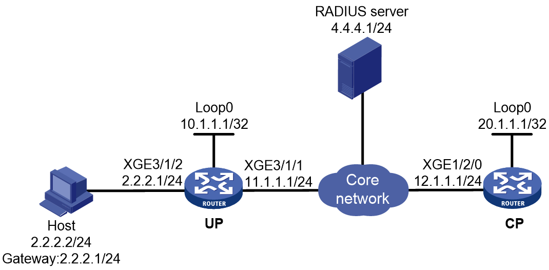
Prerequisites
Configure IP addresses for interfaces, and make sure devices can reach each other at Layer 3. (Details not shown.)
Set up the management channel, control channel, and protocol channel between the CP and UP. (Details not shown.)
Procedure
1. Configure the RADIUS server:
# Add BRAS IP address 12.1.1.1 and secret radius to the clients.conf file.
client 12.1.1.1/32 {
ipaddr = 12.1.1.1
netmask=32
secret=radius
}
# Add the username and password to the users user information file. The username is the host IP address, and the password is radius.
2.2.2.2 Cleartext-Password :="radius"
2. Configure the UP:
# Configure the device to operate in user plane mode.
<UP> system-view
[UP] work-mode user-plane
3. Configure the CP:
a. Configure a RADIUS scheme:
# Create a RADIUS scheme named rs1 and enter its view.
<CP> system-view
[CP] radius scheme rs1
# Configure primary servers and keys for authentication and accounting.
[CP-radius-rs1] primary authentication 4.4.4.1
[CP-radius-rs1] primary accounting 4.4.4.1
[CP-radius-rs1] key authentication simple radius
[CP-radius-rs1] key accounting simple radius
# Exclude the ISP name from the username sent to the RADIUS server.
[CP-radius-rs1] user-name-format without-domain
[CP-radius-rs1] quit
b. Configure the ISP domain:
# Create an ISP domain named dm1 and enter its view.
[CP] domain name dm1
# Configure dm1 to use RADIUS scheme rs1.
[CP-isp-dm1] authentication ipoe radius-scheme rs1
[CP-isp-dm1] authorization ipoe radius-scheme rs1
[CP-isp-dm1] accounting ipoe radius-scheme rs1
[CP-isp-dm1] quit
c. Configure IPoE:
# Enable IPoE and configure Layer 3 access mode on Remote-XGE 1024/3/1/2.
[CP] interface remote-xge 1024/3/1/2
[CP–Remote-XGE1024/3/1/2] ip subscriber routed enable
# Enable unclassified-IP packet initiation on Remote-XGE 1024/3/1/2.
[CP–Remote-XGE1024/3/1/2] ip subscriber initiator unclassified-ip enable
# Specify dm1 as the ISP domain for unclassified-IP users.
[CP–Remote-XGE1024/3/1/2] ip subscriber unclassified-ip domain dm1
# Configure plaintext password radius for authentication.
[CP–Remote-XGE1024/3/1/2] ip subscriber password plaintext radius
[CP–Remote-XGE1024/3/1/2] quit
Verifying the configuration
# Display IPoE session information to verify that the host has come online.
[CP] display access-user interface remote-xge 1024/3/1/2
Slot 97:
UserID Interface IP address MAC address S-/C-VLAN
Username IPv6 address Access type
0x50 R-XGE1024/3/1/2 2.2.2.2 000c-29a6-b656 -/-
2.2.2.2 - L3 IPoE dynamic
Example: Configuring DHCPv4 packet initiation (assigning a local ODAP IP address pool)
Network configuration
As shown in Figure 175, the host accesses the BRAS as a DHCP client. The BRAS performs AAA for the host through the RADIUS server.
Configure the BRAS to support IPoE in CUPS mode as follows:
· The UP connects to the host.
· The CP is the IPoE control module.
· Two transmission channels are established between the UP and CP. The CUPS channel is used to for deploying entries between the UP and CP. The VXLAN tunnel is used for transmitting protocol packets between the UP and CP.
· The UP's access module identifies the packets to be sent to the CP. The CP deploys sessions to the UP. The UP restores the deployed sessions.
This example uses the Linux Free RADIUS server.

Prerequisites
Configure IP addresses for interfaces, and make sure devices can reach each other at Layer 3. (Details not shown.)
Set up the management channel, control channel, and protocol channel between the CP and UP. (Details not shown.)
Procedure
1. Configure the RADIUS server:
# Add BRAS IP address 12.1.1.1 and secret radius to the clients.conf file.
client 12.1.1.1/32 {
ipaddr = 12.1.1.1
netmask=32
secret=radius
}
# Add the username and password to the users user information file. The username is the host MAC address 000c29a6b656, and the password is radius.
000c29a6b656 Cleartext-Password :="radius"
2. Configure the UP:
# Configure the UP to operate in user plane mode.
<UP> system-view
[UP] work-mode user-plane
3. Configure CP:
a. Configure the DHCP server:
# Configure ODAP IP address pool named pool1.
<CP> system-view
[CP] ip pool pool1 odap
[CP-ip-pool-pool1] network 1.0.0.0 8 export-route
[CP-ip-pool-pool1] subnet mask-length 16
[CP-ip-pool-pool1] gateway 1.1.1.1 8
[CP-ip-pool-pool1] forbidden-ip 1.1.1.1
[CP-ip-pool-pool1] dns-list 8.8.8.8
[CP-ip-pool-pool1] quit
# Enable the DHCP server to return a DHCP-NAK message if the client notions of their IP addresses are incorrect.
[CP] dhcp server request-ip-address check
b. Configure a RADIUS scheme:
# Create a RADIUS scheme named rs1 and enter its view.
<CP> system-view
[CP] radius scheme rs1
# Configure primary servers and keys for authentication and accounting.
[CP-radius-rs1] primary authentication 4.4.4.1
[CP-radius-rs1] primary accounting 4.4.4.1
[CP-radius-rs1] key authentication simple radius
[CP-radius-rs1] key accounting simple radius
# Exclude the ISP name from the username sent to the RADIUS server.
[CP-radius-rs1] user-name-format without-domain
[CP-radius-rs1] quit
c. Configure the ISP domain on the CP:
# Create an ISP domain named dm1 and enter its view.
[CP] domain name dm1
# Configure ISP domain dm1 to use RADIUS scheme rs1. and specify IP address pool pool1 for users in ISP domain dm1
[CP-isp-dm1] authentication ipoe radius-scheme rs1
[CP-isp-dm1] authorization ipoe radius-scheme rs1
[CP-isp-dm1] accounting ipoe radius-scheme rs1
[CP-isp-dm1] authorization-attribute ip-pool pool1
[CP-isp-dm1] quit
d. Configure IPoE:
# Enter the view of remote interface Remote-XGE 1024/3/1/2.
[CP] interface remote-xge 1024/3/1/2
# Enable IPoE and configure Layer 2 access mode on Remote-XGE 1024/3/1/2.
[CP–Remote-XGE1024/3/1/2] ip subscriber l2-connected enable
# Specify dm1 as the ISP domain for DHCP users.
[CP–Remote-XGE1024/3/1/2] ip subscriber dhcp domain dm1
# Configure plaintext password radius for authentication.
[CP–Remote-XGE1024/3/1/2] ip subscriber password plaintext radius
[CP–Remote-XGE1024/3/1/2] quit
Verifying the configuration
# Display IPoE session information on the CP to verify that the host has come online.
[CP] display access-user interface remote-xge 1024/3/1/2
Slot 97:
UserID Interface IP address MAC address S-/C-VLAN
Username IPv6 address Access type
0x5c R-XGE1024/3/1/2 1.1.0.1 000c-29a6-b656 -/-
000c29a6b656 - L2 IPoE dynamic
Example: Configuring DHCPv4 packet initiation (assigning a remote BAS IP address pool)
Network configuration
As shown in Figure 176, the host accesses the BRAS as a DHCP user. It obtains configuration information from the DHCP server. The BRAS performs AAA for the host through the RADIUS server. This example uses the Linux Free RADIUS server. After the DHCP client is abnormally logged out, the DHCP client can come online again through IPv4 packet initiation.

Prerequisites
Configure IP addresses for interfaces, and make sure devices can reach each other at Layer 3. (Details not shown.)
Set up the management channel, control channel, and protocol channel between the CP and UP. (Details not shown.)
Procedure
1. Configure the RADIUS server:
# Add BRAS IP address 12.1.1.1 and secret radius to the clients.conf file.
client 12.1.1.1/32 {
ipaddr = 12.1.1.1
netmask=32
secret=radius
}
# Add the username and password to the users user information file. The username is the host MAC address and the password is radius.
000c29a6b656 Cleartext-Password :="radius"
2. Configure the DHCP server:
# Enable DHCP.
<DHCP-server> system-view
[DHCP-server] dhcp enable
# Enable the DHCP server to return a DHCP-NAK message if the client notions of their IP addresses are incorrect.
[DHCP-server] dhcp server request-ip-address check
# Create an IP address pool named pool1 and enter its view.
[DHCP-server] ip pool pool1
# Specify the subnet 3.3.3.0/24 for dynamic allocation and DNS server 8.8.8.8 in the pool.
[DHCP-server-ip-pool-pool1] network 3.3.3.0 24
[DHCP-server-ip-pool-pool1] dns-list 8.8.8.8
# Specify gateway address 3.3.3.1 in the address pool.
[DHCP-server-ip-pool-pool1] gateway-list 3.3.3.1
# Exclude IP address 3.3.3.1 from dynamic allocation in the pool.
[DHCP-server-ip-pool-pool1] forbidden-ip 3.3.3.1
[DHCP-server-ip-pool-pool1] quit
# Configure the default route to the CP.
[DHCP-server] ip route-static 0.0.0.0 0 12.1.1.1
3. Configure the UP:
# Configure the UP to operate in user plane mode.
<UP> system-view
[UP] work-mode user-plane
4. Configure the CP:
a. Configure the DHCP relay agent:
# Create a remote BAS IP address pool pool1, specify a gateway address in the address pool, exclude IP address 3.3.3.1 from dynamic allocation in the address pool, specify a DHCP server for the address pool, and bind the address pool to UP 1024.
<CP> system-view
[CP] ip pool pool1 bas remote
[CP-ip-pool-pool1] gateway 3.3.3.1 24
[CP-ip-pool-pool1] forbidden-ip 3.3.3.1
[CP-ip-pool-pool1] remote-server 4.4.4.3
[CP-ip-pool-pool1] binding up-id 1024
[CP-ip-pool-pool1] quit
b. Configure a RADIUS scheme:
# Create a RADIUS scheme named rs1 and enter its view.
[CP] radius scheme rs1
# Configure primary servers and keys for authentication and accounting.
[CP-radius-rs1] primary authentication 4.4.4.1
[CP-radius-rs1] primary accounting 4.4.4.1
[CP-radius-rs1] key authentication simple radius
[CP-radius-rs1] key accounting simple radius
# Exclude the ISP name from the username sent to the RADIUS server.
[CP-radius-rs1] user-name-format without-domain
[CP-radius-rs1] quit
c. Configure the ISP domain:
# Create an ISP domain named dm1 and enter its view.
[CP] domain name dm1
# Configure ISP domain dm1 to use RADIUS scheme rs1 and assign a remote BAS IP address pool.
[CP-isp-dm1] authentication ipoe radius-scheme rs1
[CP-isp-dm1] authorization ipoe radius-scheme rs1
[CP-isp-dm1] accounting ipoe radius-scheme rs1
[CP-isp-dm1] authorization-attribute ip-pool pool1
[CP-isp-dm1] quit
d. Configure IPoE:
# Enable IPoE and configure Layer 2 access mode on Remote-XGE 1024/3/1/2.
[CP] interface remote-xge 1024/3/1/2
[CP–Remote-XGE1024/3/1/2] ip subscriber l2-connected enable
# Enable unclassified-IP packet initiation on Remote-XGE 1024/3/1/2, and allow abnormally logged out DHCP client to come online again through IPv4 packet initiation.
[CP–Remote-XGE1024/3/1/2] ip subscriber initiator unclassified-ip enable matching-user
# Specify dm1 as the ISP domain for DHCP users.
[CP–Remote-XGE1024/3/1/2] ip subscriber dhcp domain dm1
# Configure plaintext password radius for authentication.
[CP–Remote-XGE1024/3/1/2] ip subscriber password plaintext radius
[CP–Remote-XGE1024/3/1/2] quit
Verifying the configuration
# Display IPoE session information to verify that the host has come online.
[CP] display access-user interface remote-xge 1024/3/1/2
Slot 97:
UserID Interface IP address MAC address S-/C-VLAN
Username IPv6 address Access type
0x5c R-XGE1024/3/1/2 3.3.3.2 000c-29a6-b656 -/-
000c29a6b656 - L2 IPoE dynamic
Example: Configuring DHCPv4 packet initiation (assigning an IP address pool group)
Network configuration
As shown in Figure 177, the host accesses the BRAS as a DHCP user. Users obtain IPv4 addresses from an address pool in the IP address pool group. The BRAS performs AAA for the host through the RADIUS server. This example uses the Linux Free RADIUS server.
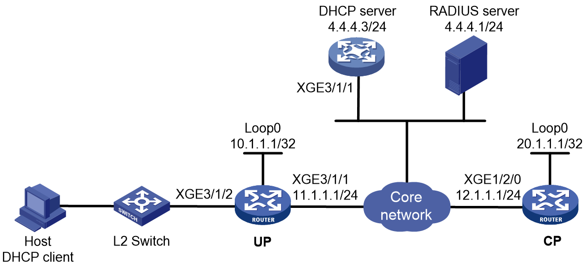
Prerequisites
Configure IP addresses for interfaces, and make sure devices can reach each other at Layer 3. (Details not shown.)
Set up the management channel, control channel, and protocol channel between the CP and UP. (Details not shown.)
Procedure
1. Configure the RADIUS server:
# Add BRAS IP address 12.1.1.1 and secret radius to the clients.conf file.
client 12.1.1.1/32 {
ipaddr = 12.1.1.1
netmask=32
secret=radius
}
# Add the usernames and passwords to the users user information file.
000c29a6b656 Cleartext-Password :="radius"
000c29a6b657 Cleartext-Password :="radius"
2. Configure the DHCP server:
# Enable DHCP.
<DHCP-server> system-view
[DHCP-server] dhcp enable
# Enable the DHCP server to return a DHCP-NAK message if the client notions of their IP addresses are incorrect.
[DHCP-server] dhcp server request-ip-address check
# Create an IP address pool named pool2 and enter its view.
[DHCP-server] ip pool pool2
# Specify the subnet 2.2.2.0/24 for dynamic allocation and DNS server 8.8.8.8 in the address pool.
[DHCP-server-ip-pool-pool2] network 2.2.2.0 24
[DHCP-server-ip-pool-pool2] dns-list 8.8.8.8
# Specify gateway address 2.2.2.1 in the address pool.
[DHCP-server-ip-pool-pool2] gateway-list 2.2.2.1
# Exclude IP address 2.2.2.1 from dynamic allocation in the address pool.
[DHCP-server-ip-pool-pool2] forbidden-ip 2.2.2.1
[DHCP-server-ip-pool-pool2] quit
# Create an IP address pool named pool3 and enter its view.
[DHCP-server] ip pool pool3
# Specify the subnet 3.3.3.0/24 for dynamic allocation and DNS server 8.8.8.8 in the pool.
[DHCP-server-ip-pool-pool3] network 3.3.3.0 24
[DHCP-server-ip-pool-pool3] dns-list 8.8.8.8
# Specify gateway address 3.3.3.1 in the address pool.
[DHCP-server-ip-pool-pool3] gateway-list 3.3.3.1
# Exclude IP address 3.3.3.1 from dynamic allocation in the pool.
[DHCP-server-ip-pool-pool3] forbidden-ip 3.3.3.1
[DHCP-server-ip-pool-pool3] quit
# Configure the default route to the CP.
[DHCP-server] ip route-static 0.0.0.0 0 12.1.1.1
3. Configure the UP:
# Configure the UP to operate in user plane mode.
<UP> system-view
[UP] work-mode user-plane
4. Configure the CP:
a. Configure the DHCP server:
<CP> system-view
# Create a local BAS IP address pool pool1.
[CP] ip pool pool1 bas local
# Specify gateway address 1.1.1.1 and DNS server 8.8.8.8 in the address pool.
[CP-ip-pool-pool1] gateway 1.1.1.1 24
[CP-ip-pool-pool1] dns-list 8.8.8.8
# Exclude IP address 1.1.1.1 from dynamic allocation in the address pool.
[CP-ip-pool-pool1] forbidden-ip 1.1.1.1
# Bind the address pool to UP 1024.
[CP-ip-pool-pool1] binding up-id 1024
[CP-ip-pool-pool1] quit
# Enable the DHCP server to return a DHCP-NAK message if the client notions of their IP addresses are incorrect.
[CP] dhcp server request-ip-address check
b. Configure the DHCP relay agent:
# Create a remote BAS IP address pool pool2, specify a gateway address in the address pool, exclude IP address 2.2.2.1 from dynamic allocation in the address pool, specify a DHCP server for the address pool, and bind the address pool to UP 1024.
[CP] ip pool pool2 bas remote
[CP-ip-pool-pool2] gateway 2.2.2.1 24
[CP-ip-pool-pool2] forbidden-ip 2.2.2.1
[CP-ip-pool-pool2] remote-server 4.4.4.3
[CP-ip-pool-pool2] binding up-id 1024
[CP-ip-pool-pool2] quit
# Create a remote BAS IP address pool pool3, specify a gateway address in the address pool, exclude IP address 3.3.3.1 from dynamic allocation in the address pool, specify a DHCP server for the address pool, and bind the address pool to UP 1024.
[CP] ip pool pool3 bas remote
[CP-ip-pool-pool3] gateway 3.3.3.1 24
[CP-ip-pool-pool3] forbidden-ip 3.3.3.1
[CP-ip-pool-pool3] remote-server 4.4.4.3
[CP-ip-pool-pool3] binding up-id 1024
[CP-ip-pool-pool3] quit
# Create IP address pool group poolgroup1, and assign local BAS IP address pool pool1 and remote BAS IP address pools pool2 and pool3 to the IP address pool group.
[CP] ip pool-group poolgroup1
[CP-ip-pool-group-poolgroup1] pool pool1
[CP-ip-pool-group-poolgroup1] pool pool2
[CP-ip-pool-group-poolgroup1] pool pool3
[CP-ip-pool-group-poolgroup1] quit
c. Configure a RADIUS scheme:
# Create a RADIUS scheme named rs1 and enter its view.
[CP] radius scheme rs1
# Configure primary servers and keys for authentication and accounting.
[CP-radius-rs1] primary authentication 4.4.4.1
[CP-radius-rs1] primary accounting 4.4.4.1
[CP-radius-rs1] key authentication simple radius
[CP-radius-rs1] key accounting simple radius
# Exclude the ISP name from the username sent to the RADIUS server.
[CP-radius-rs1] user-name-format without-domain
[CP-radius-rs1] quit
d. Configure the ISP domain:
# Create an ISP domain named dm1 and enter its view.
[CP] domain name dm1
# Configure ISP domain dm1 to use RADIUS scheme rs1 and assign an IP address pool group.
[CP-isp-dm1] authentication ipoe radius-scheme rs1
[CP-isp-dm1] authorization ipoe radius-scheme rs1
[CP-isp-dm1] accounting ipoe radius-scheme rs1
[CP-isp-dm1] authorization-attribute ip-pool-group poolgroup1
[CP-isp-dm1] quit
e. Configure IPoE:
# Enable IPoE and configure Layer 2 access mode on Remote-XGE 1024/3/1/2.
[CP] interface remote-xge 1024/3/1/2
[CP–Remote-XGE1024/3/1/2] ip subscriber l2-connected enable
# Specify ISP domain dm1 as the ISP domain for DHCP users.
[CP–Remote-XGE1024/3/1/2] ip subscriber dhcp domain dm1
# Configure plaintext password radius for authentication.
[CP–Remote-XGE1024/3/1/2] ip subscriber password plaintext radius
[CP–Remote-XGE1024/3/1/2] quit
Verifying the configuration
# After 253 users come online, display the statistics of the local DHCP address group pool1.
[CP] display dhcp server statistics pool pool1
Total IP addresses: 254
Free IP addresses: 0
Used: 253
Pool utilization: 100.00%
Bindings:
Automatic: 253
Manual: 0
Expired: 0
Conflicts: 0
The output shows that the usage of local DHCP address group pool1 is 100% and does not have allocable IP addresses.
When the resources in local IP address group pool1 are exhausted, the address resources on the DHCP server associated with remote BAS IP address pool pool2 are used to allocate IP addresses to new users.
Example: Configuring DHCPv6 packet initiation (assigning a local ODAP IPv6 address pool)
Network configuration
As shown in Figure 178, the host accesses the BRAS as a DHCP client. The BRAS performs AAA for the host through the RADIUS server.
Configure the BRAS to support IPoE in CUPS mode as follows:
· The UP connects to the host.
· The CP is the IPoE control module.
· Two transmission channels are established between the UP and CP. The CUPS channel is used to for deploying entries between the UP and CP. The VXLAN tunnel is used for transmitting protocol packets between the UP and CP.
· The UP's access module identifies the packets to be sent to the CP. The CP deploys sessions to the UP. The UP restores the deployed sessions.
This example uses the Linux Free RADIUS server.
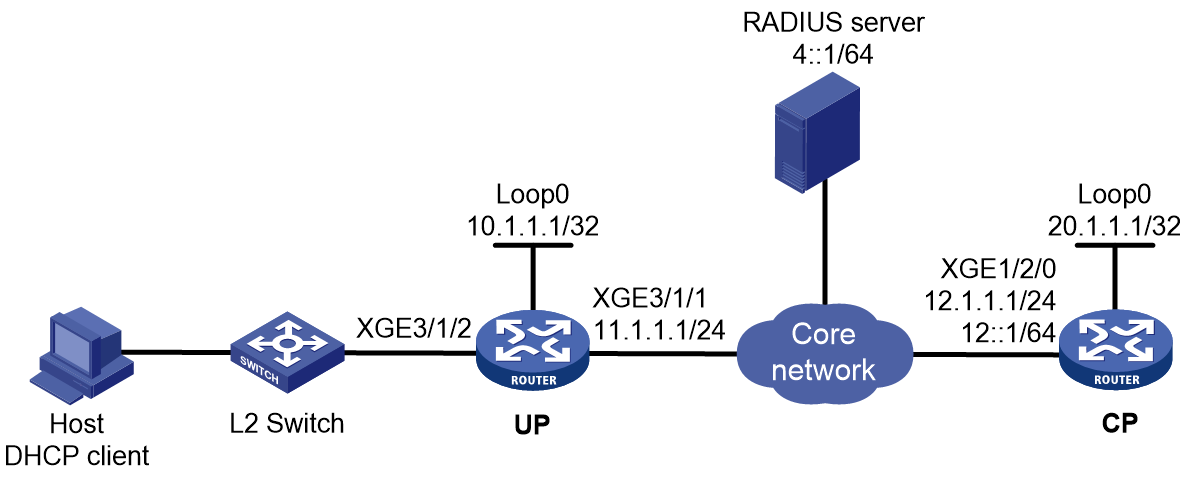
Prerequisites
Configure IP addresses for interfaces, and make sure devices can reach each other at Layer 3. (Details not shown.)
Set up the management channel, control channel, and protocol channel between the CP and UP. (Details not shown.)
Procedure
1. Configure the RADIUS server:
# Add BRAS IP address 12::1 and secret radius to the clients.conf file.
client 12::1/64 {
ipaddr6 = 12::1
netmask=64
secret=radius
}
# Add the username and password to the users user information file. The username is the host MAC address 000c29a6b656, and the password is radius.
000c29a6b656 Cleartext-Password :="radius"
2. Configure the UP:
# Configure the BRAS to operate in user plane mode.
<UP> system-view
[UP] work-mode user-plane
3. Configure CP:
a. Configure the DHCP server:
# Configure the ODAP IPv6 address pool named pool1.
<CP> system-view
[CP] ipv6 pool pool1 odap
[CP-ipv6-pool-pool1] network 1::/32 export-route
[CP-ipv6-pool-pool1] dynamic address assign-length 64
[CP-ipv6-pool-pool1] forbidden-address 1::1
[CP-ipv6-pool-pool1] dns-server 8::8
[CP-ipv6-pool-pool1] quit
# Enable the DHCPv6 server on remote interface Remote-XGE 1024/3/1/2.
[CP] interface remote-xge 1024/3/1/2
[CP–Remote-XGE1024/3/1/1] ipv6 dhcp select server
# Configure Remote-XGE 1024/3/1/2 to automatically generate a link-local address, which is to be used as the gateway address for users.
[CP–Remote-XGE1024/3/1/2] ipv6 address auto link-local
# Disable RA message suppression on Remote-XGE 1024/3/1/2.
[CP–Remote-XGE1024/3/1/2] undo ipv6 nd ra halt
# Set the managed address configuration flag (M) to 1 in RA advertisements to be sent. Then, the host uses a DHCPv6 server to obtain IPv6 addresses.
[CP–Remote-XGE1024/3/1/2] ipv6 nd autoconfig managed-address-flag
# Set the other stateful configuration flag (O) to 1 in RA advertisements to be sent. Then, the host uses a DHCPv6 server to obtain configuration information other than IPv6 addresses.
[CP–Remote-XGE1024/3/1/2] ipv6 nd autoconfig other-flag
[CP–Remote-XGE1024/3/1/2] quit
b. Configure a RADIUS scheme:
# Create a RADIUS scheme named rs1 and enter its view.
<CP> system-view
[CP] radius scheme rs1
# Configure primary servers and keys for authentication and accounting.
[CP-radius-rs1] primary authentication ipv6 4::1
[CP-radius-rs1] primary accounting ipv6 4::1
[CP-radius-rs1] key authentication simple radius
[CP-radius-rs1] key accounting simple radius
# Exclude the ISP name from the username sent to the RADIUS server.
[CP-radius-rs1] user-name-format without-domain
[CP-radius-rs1] quit
c. Configure the ISP domain on the CP:
# Create an ISP domain named dm1 and enter its view.
[CP] domain name dm1
# Configure ISP domain dm1 to use RADIUS scheme rs1 and specify IPv6 address pool pool1 for users in ISP domain dm1
[CP-isp-dm1] authentication ipoe radius-scheme rs1
[CP-isp-dm1] authorization ipoe radius-scheme rs1
[CP-isp-dm1] accounting ipoe radius-scheme rs1
[CP-isp-dm1] authorization-attribute ipv6-pool pool1
[CP-isp-dm1] quit
d. Configure IPoE:
# Enter the view of remote interface Remote-XGE 1024/3/1/2.
[CP] interface remote-xge 1024/3/1/2
# Enable IPoE and configure Layer 2 access mode on Remote-XGE 1024/3/1/2.
[CP–Remote-XGE1024/3/1/2] ip subscriber l2-connected enable
# Specify dm1 as the ISP domain for DHCPv6 users.
[CP–Remote-XGE1024/3/1/2] ip subscriber dhcp domain dm1
# Configure plaintext password radius for authentication.
[CP–Remote-XGE1024/3/1/2] ip subscriber password plaintext radius
[CP–Remote-XGE1024/3/1/2] quit
Verifying the configuration
# Display IPoE session information on the CP to verify that the host has come online.
[CP] display access-user interface remote-xge 1024/3/1/2
Slot 97:
UserID Interface IP address MAC address S-/C-VLAN
Username IPv6 address Access type
0x5c R-XGE1024/3/1/2 - 000c-29a6-b656 -/-
000c29a6b656 1::2 L2 IPoE dynamic
Example: Configuring DHCPv6 packet initiation (assigning a remote BAS IPv6 address pool)
Network configuration
As shown in Figure 179, the host accesses the BRAS as a DHCP user. It obtains configuration information from the DHCP server. The BRAS performs AAA for the host through the RADIUS server. This example uses the Linux Free RADIUS server.
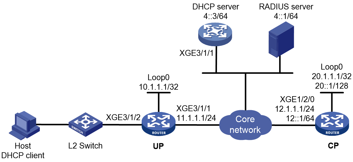
Prerequisites
Configure IP addresses for interfaces, and make sure devices can reach each other at Layer 3. (Details not shown.)
Set up the management channel, control channel, and protocol channel between the CP and UP. (Details not shown.)
Procedure
1. Configure the RADIUS server:
# Add BRAS IP address 12::1 and secret radius to the clients.conf file.
client 12::1/64 {
ipaddr6 = 12::1
netmask=64
secret=radius
}
# Add the username and password to the users user information file. The username is the host MAC address and the password is radius.
000c29a6b656 Cleartext-Password :="radius"
2. Configure the DHCP server:
# Create an IPv6 address pool named pool1 and enter its view.
<DHCP-server> system-view
[DHCP-server] ipv6 pool pool1
# Specify the IPv6 subnet 3::/64 for dynamic allocation and specify DNS server 8::8 in the address pool pool1.
[DHCP-server-ipv6-pool-pool1] network 3::/64
[DHCP-server-ipv6-pool-pool1] dns-server 8::8
[DHCP-server-ipv6-pool-pool1] quit
# Enable the DHCPv6 server on Ten-GigabitEthernet 3/1/1.
[DHCP-server] interface ten-gigabitethernet 3/1/1
[DHCP-server-Ten-GigabitEthernet3/1/1] ipv6 dhcp select server
[DHCP-server-Ten-GigabitEthernet3/1/1] quit
# Configure the default route to the CP.
[DHCP-server] ipv6 route-static :: 0 12::1
3. Configure the UP:
# Configure the UP to operate in user plane mode.
<UP> system-view
[UP] work-mode user-plane
4. Configure the CP:
a. Configure the DHCP relay agent:
# Create a remote BAS IPv6 address pool pool1.
<CP> system-view
[CP] ipv6 pool pool1
[CP-ipv6-pool-pool1] gateway-list 3::1 bas remote
[CP-ipv6-pool-pool1] network 3::/64 export-route
[CP-ipv6-pool-pool1] remote-server 4::3
[CP-ipv6-pool-pool1] dhcpv6-relay source-address interface loopback 0
[CP-ipv6-pool-pool1] binding up-id 1024
[CP-ipv6-pool-pool1] quit
# Enable the DHCPv6 relay agent on Remote-XGE 1024/3/1/2.
[CP] interface remote-xge 1024/3/1/2
[CP–Remote-XGE1024/3/1/2] ipv6 dhcp select relay
# Automatically generate a link-local address for Remote-XGE 1024/3/1/2.
[CP–Remote-XGE1024/3/1/2] ipv6 address auto link-local
# Disable RA message suppression on Remote-XGE 1024/3/1/2.
[CP–Remote-XGE1024/3/1/2] undo ipv6 nd ra halt
# Set the managed address configuration flag (M) to 1 in RA advertisements to be sent. Then, the host uses a DHCPv6 server to obtain IPv6 addresses.
[CP–Remote-XGE1024/3/1/2] ipv6 nd autoconfig managed-address-flag
# Set the other stateful configuration flag (O) to 1 in RA advertisements to be sent. Then, the host uses a DHCPv6 server to obtain configuration information other than IPv6 addresses.
[CP–Remote-XGE1024/3/1/2] ipv6 nd autoconfig other-flag
[CP–Remote-XGE1024/3/1/2] quit
b. Configure a RADIUS scheme:
# Create a RADIUS scheme named rs1 and enter its view.
[CP] radius scheme rs1
# Configure primary servers and keys for authentication and accounting.
[CP-radius-rs1] primary authentication ipv6 4::1
[CP-radius-rs1] primary accounting ipv6 4::1
[CP-radius-rs1] key authentication simple radius
[CP-radius-rs1] key accounting simple radius
# Exclude the ISP name from the username sent to the RADIUS server.
[CP-radius-rs1] user-name-format without-domain
[CP-radius-rs1] quit
c. Configure the ISP domain:
# Create an ISP domain named dm1 and enter its view.
[CP] domain name dm1
# Configure ISP domain dm1 to use RADIUS scheme rs1 and assign a remote IPv6 address pool.
[CP-isp-dm1] authentication ipoe radius-scheme rs1
[CP-isp-dm1] authorization ipoe radius-scheme rs1
[CP-isp-dm1] accounting ipoe radius-scheme rs1
[CP-isp-dm1] authorization-attribute ipv6-pool pool1
[CP-isp-dm1] quit
d. Configure IPoE:
# Enable IPoE and configure Layer 2 access mode on Remote-XGE 1024/3/1/2.
[CP] interface remote-xge 1024/3/1/2
[CP–Remote-XGE1024/3/1/2] ip subscriber l2-connected enable
# Specify dm1 as the ISP domain for DHCP users.
[CP–Remote-XGE1024/3/1/2] ip subscriber dhcp domain dm1
# Configure plaintext password radius for authentication.
[CP–Remote-XGE1024/3/1/2] ip subscriber password plaintext radius
[CP–Remote-XGE1024/3/1/2] quit
Verifying the configuration
# Display IPoE session information to verify that the host has come online and obtained IPv6 address 3::2.
[CP] display access-user interface remote-xge 1024/3/1/2
Slot 97:
UserID Interface IP address MAC address S-/C-VLAN
Username IPv6 address Access type
0x2c2 R-XGE1024/3/1/2 - 000c-29a6-b656 -/-
000c29a6b656 3::2 L2 IPoE dynamic
Example: Configuring a dual-stack user (assigning remote BAS IP and IPv6 address pools)
Network configuration
As shown in Figure 180, the host accesses the BRAS as a dual-stack user. The host obtains IPv4 and IPv6 addresses from the DHCP server. The BRAS performs AAA for the host through the RADIUS server. This example uses the Linux Free RADIUS server.
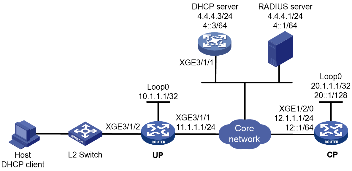
Prerequisites
Configure IP addresses for interfaces, and make sure devices can reach each other at Layer 3. (Details not shown.)
Set up the management channel, control channel, and protocol channel between the CP and UP. (Details not shown.)
Procedure
1. Configure the RADIUS server:
# Add BRAS IP address 12.1.1.1 and secret radius to the clients.conf file.
client 12.1.1.1/32 {
ipaddr = 12.1.1.1
netmask=32
secret=radius
}
# Add the username and password to the users user information file. The username is the host MAC address and the password is radius.
000c29a6b656 Cleartext-Password :="radius"
2. Configure the DHCP server:
a. Configure an IP address pool:
# Enable DHCP.
<DHCP-server> system-view
[DHCP-server] dhcp enable
# Enable the DHCP server to return a DHCP-NAK message if the client notions of their IP addresses are incorrect.
[DHCP-server] dhcp server request-ip-address check
# Create an IP address pool named pool1 and enter its view.
[DHCP-server] ip pool pool1
# Specify the subnet 3.3.3.0/24 for dynamic allocation and DNS server 8.8.8.8 in the pool.
[DHCP-server-ip-pool-pool1] network 3.3.3.0 24
[DHCP-server-ip-pool-pool1] dns-list 8.8.8.8
# Specify gateway address 3.3.3.1 in the address pool.
[DHCP-server-ip-pool-pool1] gateway-list 3.3.3.1
# Exclude IP address 3.3.3.1 from dynamic allocation in the pool.
[DHCP-server-ip-pool-pool1] forbidden-ip 3.3.3.1
[DHCP-server-ip-pool-pool1] quit
# Configure the default route to the CP.
[DHCP-server] ip route-static 0.0.0.0 0 12.1.1.1
b. Configure an IPv6 address pool:
# Create an IPv6 address pool named pool2 and enter its view.
[DHCP-server] ipv6 pool pool2
# Specify the subnet 3::/64 for dynamic allocation and DNS server 8::8 in the pool.
[DHCP-server-ipv6-pool-pool2] network 3::/64
[DHCP-server-ipv6-pool-pool2] dns-server 8::8
[DHCP-server-ipv6-pool-pool2] quit
# Exclude IPv6 address 3::1 from dynamic allocation in the pool.
[DHCP-server] ipv6 dhcp server forbidden-address 3::1
# Enable the DHCPv6 server on Ten-GigabitEthernet 3/1/1.
[DHCP-server] interface ten-gigabitethernet 3/1/1
[DHCP-server-Ten-GigabitEthernet3/1/1] ipv6 dhcp select server
[DHCP-server-Ten-GigabitEthernet3/1/1] quit
# Configure the default route to the CP.
[DHCP-server] ipv6 route-static :: 0 12::1
3. Configure the UP:
# Configure the UP to operate in user plane mode.
<UP> system-view
[UP] work-mode user-plane
4. Configure the BRAS:
a. Configure the DHCP relay agent:
# Create a remote BAS IP address pool pool1.
<CP> system-view
[CP] ip pool pool1 bas remote
[CP-ip-pool-pool1] gateway 3.3.3.1 24
[CP-ip-pool-pool1] forbidden-ip 3.3.3.1
[CP-ip-pool-pool1] remote-server 4.4.4.3
[CP-ip-pool-pool1] binding up-id 1024
[CP-ip-pool-pool1] quit
# Create a remote IPv6 address pool pool2.
[CP] ipv6 pool pool2
[CP-ipv6-pool-pool2] gateway-list 3::1
[CP-ipv6-pool-pool2] network 3::/64 export-route
[CP-ipv6-pool-pool2] remote-server 4::3
[CP-ipv6-pool-pool2] dhcpv6-relay source-address interface loopback 0
[CP-ipv6-pool-pool2] binding up-id 1024
[CP-ipv6-pool-pool2] quit
# Enable the DHCPv4 relay agent and DHCPv6 relay agent on Remote-XGE 1024/3/1/2.
[CP] interface remote-xge 1024/3/1/2
[CP–Remote-XGE1024/3/1/2] dhcp select relay
[CP–Remote-XGE1024/3/1/2] ipv6 dhcp select relay
# Automatically generate a link-local address for Remote-XGE 1024/3/1/2.
[CP–Remote-XGE1024/3/1/2] ipv6 address auto link-local
# Disable RA message suppression on Remote-XGE 1024/3/1/2.
[CP–Remote-XGE1024/3/1/2] undo ipv6 nd ra halt
# Set the managed address configuration flag (M) to 1 in RA advertisements to be sent. Then, the host uses a DHCPv6 server to obtain IPv6 addresses.
[CP–Remote-XGE1024/3/1/2] ipv6 nd autoconfig managed-address-flag
# Set the other stateful configuration flag (O) to 1 in RA advertisements to be sent. Then, the host uses a DHCPv6 server to obtain configuration information other than IPv6 addresses.
[CP–Remote-XGE1024/3/1/2] ipv6 nd autoconfig other-flag
[CP–Remote-XGE1024/3/1/2] quit
b. Configure a RADIUS scheme:
# Create a RADIUS scheme named rs1 and enter its view.
[CP] radius scheme rs1
# Configure primary servers and keys for authentication and accounting.
[CP-radius-rs1] primary authentication 4.4.4.1
[CP-radius-rs1] primary accounting 4.4.4.1
[CP-radius-rs1] key authentication simple radius
[CP-radius-rs1] key accounting simple radius
# Exclude the ISP name from the username sent to the RADIUS server.
[CP-radius-rs1] user-name-format without-domain
[CP-radius-rs1] quit
c. Configure the ISP domain:
# Create an ISP domain named dm1 and enter its view.
[CP] domain name dm1
# Configure ISP domain dm1 to use RADIUS scheme rs1 and assign address pools.
[CP-isp-dm1] authentication ipoe radius-scheme rs1
[CP-isp-dm1] authorization ipoe radius-scheme rs1
[CP-isp-dm1] accounting ipoe radius-scheme rs1
[CP-isp-dm1] authorization-attribute ip-pool pool1
[CP-isp-dm1] authorization-attribute ipv6-pool pool2
[CP-isp-dm1] quit
d. Configure IPoE:
# Enable IPoE and configure Layer 2 access mode on Remote-XGE 1024/3/1/2.
[CP] interface remote-xge 1024/3/1/2
[CP–Remote-XGE1024/3/1/2] ip subscriber l2-connected enable
# Specify dm1 as the ISP domain for DHCP users.
[CP–Remote-XGE1024/3/1/2] ip subscriber dhcp domain dm1
# Configure plaintext password radius for authentication.
[CP–Remote-XGE1024/3/1/2] ip subscriber password plaintext radius
[CP–Remote-XGE1024/3/1/2] quit
Verifying the configuration
# Display IPoE session information to verify that the host has come online.
[CP] display access-user interface remote-xge 1024/3/1/2
UserID Interface IP address MAC address S-/C-VLAN
Username IPv6 address Access type
0x2c2 R-XGE1024/3/1/2 3.3.3.2 000c-29a6-b656 -/-
000c29a6b656 3::2 L2 IPoE dynamic
Example: Configuring IPv6 ND RS packet initiation (AAA-authorized prefix)
Network configuration
As shown in Figure 181, the host accesses the BRAS as an IPv6 ND RS user. The BRAS performs AAA for the host through the RADIUS server. This example uses the Linux Free RADIUS server.
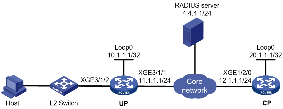
Prerequisites
Configure IP addresses for interfaces, and make sure devices can reach each other at Layer 3. (Details not shown.)
Set up the management channel, control channel, and protocol channel between the CP and UP. (Details not shown.)
Procedure
1. Configure the RADIUS server:
# Add BRAS IP address 12.1.1.1 and secret radius to the clients.conf file.
client 12.1.1.1/32 {
ipaddr = 12.1.1.1
netmask=32
secret=radius
}
# Add the username and password to the users user information file. The username is the host MAC address, and the password is radius.
000c29a6b656 Cleartext-Password :="radius"
2. Configure the UP:
# Configure the UP to operate in user plane mode.
<UP> system-view
[UP] work-mode user-plane
3. Configure the CP:
a. Disable RA message suppression on Remote-XGE 1024/3/1/2.
<CP> system-view
[CP] interface remote-xge 1024/3/1/2
[CP–Remote-XGE1024/3/1/2] undo ipv6 nd ra halt
b. Automatically generate a link-local address for Remote-XGE 1024/3/1/2.
[CP–Remote-XGE1024/3/1/2] ipv6 address auto link-local
[CP–Remote-XGE1024/3/1/2] quit
c. Configure a RADIUS scheme:
# Create a RADIUS scheme named rs1 and enter its view.
[CP] radius scheme rs1
# Configure primary servers and keys for authentication and accounting.
[CP-radius-rs1] primary authentication 4.4.4.1
[CP-radius-rs1] primary accounting 4.4.4.1
[CP-radius-rs1] key authentication simple radius
[CP-radius-rs1] key accounting simple radius
# Exclude the ISP name from the username sent to the RADIUS server.
[CP-radius-rs1] user-name-format without-domain
[CP-radius-rs1] quit
d. (Applicable only to advertising prefix subnet routes.) Create a local BAS IPv6 address pool named pool1 and enter its view. Specify the subnet for DHCPv6 clients and advertise the subnet route.
[CP] ipv6 pool pool1 bas local
[CP-ipv6-pool-pool1] network 10::/64 export-route
[CP-ipv6-pool-pool1] quit
e. Configure the ISP domain:
# Create an ISP domain named dm1 and enter its view.
[CP] domain name dm1
# Configure dm1 to use RADIUS scheme rs1.
[CP-isp-dm1] authentication ipoe radius-scheme rs1
[CP-isp-dm1] authorization ipoe radius-scheme rs1
[CP-isp-dm1] accounting ipoe radius-scheme rs1
# Authorize a IPv6 DNS address pool to users.
[CP-isp-dm1] authorization-attribute primary-dns ipv6 8::8
[CP-isp-dm1] quit
f. Configure IPoE:
# Enable IPoE and configure Layer 2 access mode on Remote-XGE 1024/3/1/2.
[CP] interface remote-xge 1024/3/1/2
[CP–Remote-XGE1024/3/1/2] ip subscriber l2-connected enable
# Enable IPv6 ND RS packet initiation on Remote-XGE 1024/3/1/2.
[CP–Remote-XGE1024/3/1/2] ip subscriber initiator ndrs enable
# Specify dm1 as the ISP domain for IPv6 ND RS users.
[CP–Remote-XGE1024/3/1/2] ip subscriber ndrs domain dm1
# Configure plaintext password radius for authentication.
[CP–Remote-XGE1024/3/1/2] ip subscriber password plaintext radius
[CP–Remote-XGE1024/3/1/2] quit
Verifying the configuration
# Display IPoE session information to verify that the host has come online.
[CP] display access-user interface remote-xge 1024/3/1/2
Slot 97:
UserID Interface IP address MAC address S-/C-VLAN
Username IPv6 address Access type
0xc R-XGE1024/3/1/2 - 000c-29a6-b656 -/-
000c29a6b656 10::20C:29FF:FEA6:B6 L2 IPoE dynamic
56
Example: Configuring IPv6 ND RS packet initiation (ND prefix pool-authorized prefix)
Network configuration
As shown in Figure 182, the host accesses the BRAS as an IPv6 ND RS user. The BRAS performs AAA for the host through the RADIUS server. This example uses the Linux Free RADIUS server.

Prerequisites
Configure IP addresses for interfaces, and make sure devices can reach each other at Layer 3. (Details not shown.)
Set up the management channel, control channel, and protocol channel between the CP and UP. (Details not shown.)
Procedure
1. Configure the RADIUS server:
# Add BRAS IP address 12.1.1.1 and secret radius to the clients.conf file.
client 12.1.1.1/32 {
ipaddr = 12.1.1.1
netmask=32
secret=radius
}
# Add the username and password to the users user information file. The username is the host MAC address, and the password is radius.
000c29a6b656 Cleartext-Password :="radius"
2. Configure the UP:
# Configure the UP to operate in user plane mode.
<UP> system-view
[UP] work-mode user-plane
3. Configure the CP:
a. Disable RA message suppression on Remote-XGE 1024/3/1/2.
<CP> system-view
[CP] interface remote-xge 1024/3/1/2
[CP–Remote-XGE1024/3/1/2] undo ipv6 nd ra halt
b. Automatically generate a link-local address for Remote-XGE 1024/3/1/2.
[CP–Remote-XGE1024/3/1/2] ipv6 address auto link-local
[CP–Remote-XGE1024/3/1/2] quit
c. Configure the ND prefix pool:
# Create prefix pool 1 that contains the prefix 10::/16 and specify the length of prefixes to be assigned as 32. Prefix pool 1 can assign 65536 prefixes in the range of 10::/32 to 10:FFFF::/32.
[CP] ipv6 dhcp prefix-pool 1 prefix 10::/16 assign-len 32
# Create an ODAP IPv6 address pool named pool1, and apply prefix pool 1. Specify IPv6 prefix length 64 for IPv6 prefix range assignment in the IPv6 address pool.
[CP] ipv6 pool pool1 odap
[CP-ipv6-pool-pool1] prefix-pool 1
[CP-ipv6-pool-pool1] dynamic prefix assign-length 64
[CP-ipv6-pool-pool1] quit
d. Configure a RADIUS scheme:
# Create a RADIUS scheme named rs1 and enter its view.
[CP] radius scheme rs1
# Configure primary servers and keys for authentication and accounting.
[CP-radius-rs1] primary authentication 4.4.4.1
[CP-radius-rs1] primary accounting 4.4.4.1
[CP-radius-rs1] key authentication simple radius
[CP-radius-rs1] key accounting simple radius
# Exclude the ISP name from the username sent to the RADIUS server.
[CP-radius-rs1] user-name-format without-domain
[CP-radius-rs1] quit
e. Configure the ISP domain:
# Create an ISP domain named dm1 and enter its view.
[CP] domain name dm1
# Configure dm1 to use RADIUS scheme rs1, and authorize an ND prefix pool and IPv6 DNS address pool to users.
[CP-isp-dm1] authentication ipoe radius-scheme rs1
[CP-isp-dm1] authorization ipoe radius-scheme rs1
[CP-isp-dm1] accounting ipoe radius-scheme rs1
[CP-isp-dm1] authorization-attribute ipv6-nd-prefix-pool pool1
[CP-isp-dm1] authorization-attribute primary-dns ipv6 8::8
[CP-isp-dm1] quit
f. Configure IPoE:
# Enable IPoE and configure Layer 2 access mode on Remote-XGE 1024/3/1/2.
[CP] interface remote-xge 1024/3/1/2
[CP–Remote-XGE1024/3/1/2] ip subscriber l2-connected enable
# Enable IPv6 ND RS packet initiation on Remote-XGE 1024/3/1/2.
[CP–Remote-XGE1024/3/1/2] ip subscriber initiator ndrs enable
# Specify dm1 as the ISP domain for IPv6 ND RS users.
[CP–Remote-XGE1024/3/1/2] ip subscriber ndrs domain dm1
# Configure plaintext password radius for authentication.
[CP–Remote-XGE1024/3/1/2] ip subscriber password plaintext radius
[CP–Remote-XGE1024/3/1/2] quit
Verifying the configuration
# Display IPoE session information to verify that the host has come online.
[CP] display access-user interface remote-xge 1024/3/1/2
Slot 97:
UserID Interface IP address MAC address S-/C-VLAN
Username IPv6 address Access type
0xc R-XGE1024/3/1/2 - 000c-29a6-b656 -/-
000c29a6b656 10::20C:29FF:FEA6:B6 L2 IPoE dynamic
56
Example: Configuring IPv6 ND RS+DHCPv6 (IA_PD) initiation
Network configuration
As shown in Figure 183, the CPE supports applying for ND prefixes and PD prefixes from the BRAS through the following methods:
· NDRA—The CPE actively sends an ND RS packet to the BRAS. The BRAS returns an ND prefix to Ten-GigabitEthernet 3/1/1 on the connected CPE through an ND RA packet. The CPE uses the ND prefix to generate a global unicast IPv6 address for Ten-GigabitEthernet 3/1/1. The IPv6 address is used for remotely managing the CPE.
· IA_PD—The CPE actively sends DHCPv6 requests to the CPE. The BRAS allocates a PD prefix to the CPE through DHCPv6 (IA_PD). The CPE automatically allocates the obtained PD prefix to the attached hosts. These hosts use the PD prefix to generate global unicast IPv6 addresses.
Use the RADIUS server as the authentication, authorization, and accounting server.
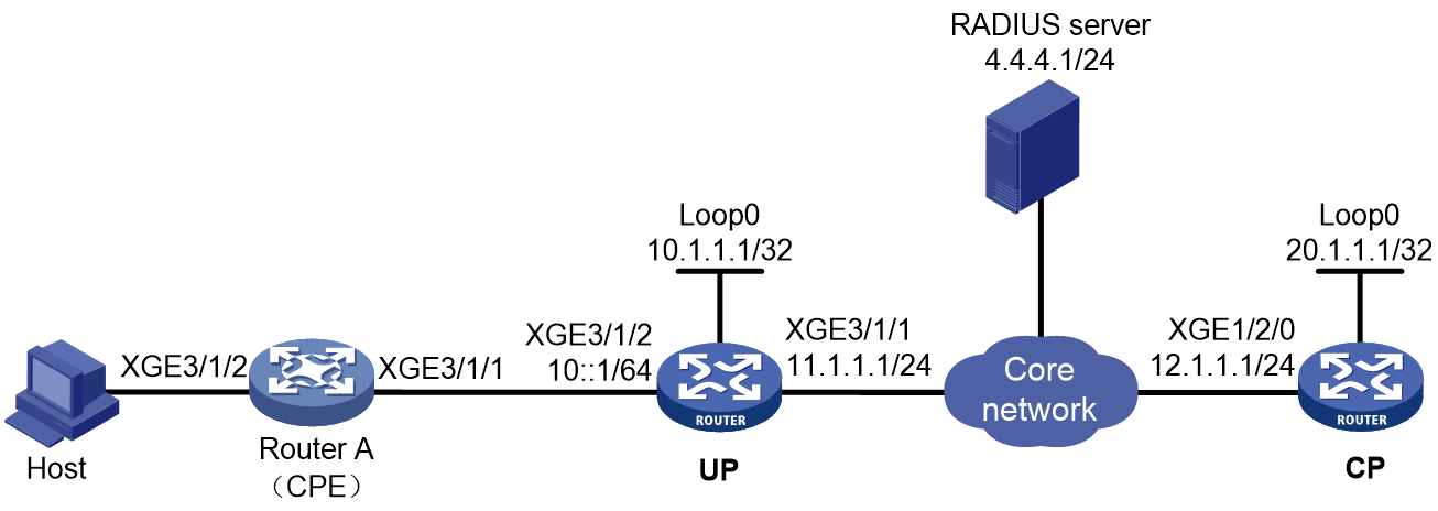
Prerequisites
Configure IP addresses for interfaces, and make sure devices can reach each other at Layer 3. (Details not shown.)
Set up the management channel, control channel, and protocol channel between the CP and UP. (Details not shown.)
Procedure
1. Configuring the RADIUS server:
This section uses the Linux Free RADIUS server as an example.
# Configure the RADIUS client IP address as 12.1.1.1 and configure the shared key as radius.
client 12.1.1.1/32 {
ipaddr = 12.1.1.1
netmask=32
secret=radius
}
# Add the username and password to the users user information file. The username is the host MAC address 6a4c310a0207 and the password is radius.
6a4c310a0207 Cleartext-Password :="radius"
2. Configure the UP:
# Configure the UP to operate in user plane mode.
<UP> system-view
[UP] work-mode user-plane
3. Configure the CP:
a. Disable RA message suppression on Remote-XGE 1024/3/1/2.
<CP> system-view
[CP] interface remote-xge 1024/3/1/2
[CP–Remote-XGE1024/3/1/2] undo ipv6 nd ra halt
b. Automatically generate a link-local address for Remote-XGE 1024/3/1/2.
[CP–Remote-XGE1024/3/1/2] ipv6 address auto link-local
c. Enable the DHCPv6 server on Remote-XGE 1024/3/1/2.
[CP–Remote-XGE1024/3/1/2] ipv6 dhcp select server
[CP–Remote-XGE1024/3/1/2] quit
d. Configure the ND prefix pool and PD prefix pool:
# (For NDRS.) Create prefix pool 1 that contains the prefix 10::/16 and specify the length of prefixes to be assigned as 32. Prefix pool 1 can assign 65536 prefixes in the range of 10::/32 to 10:FFFF::/32.
[CP] ipv6 dhcp prefix-pool 1 prefix 10::/16 assign-len 32
# Create an ODAP IPv6 address pool named nd, and apply prefix pool 1. Specify IPv6 prefix length 64 for IPv6 prefix range assignment in the IPv6 address pool.
[CP] ipv6 pool nd odap
[CP-ipv6-pool-nd] prefix-pool 1
[CP-ipv6-pool-nd] dynamic prefix assign-length 64
[CP-ipv6-pool-nd] quit
# (For IA_PD.) Create prefix pool 6 that contains the prefix 20::/16 and specify the length of prefixes to be assigned as 32. Prefix pool 6 can assign 65536 prefixes in the range of 20::/32 to 20:FFFF::/32.
[CP] ipv6 dhcp prefix-pool 6 prefix 20::/16 assign-len 32
# Create an ODAP IPv6 address pool named pd, and apply prefix pool 6. Specify IPv6 prefix length 64 for IPv6 prefix range assignment in the IPv6 address pool.
[CP] ipv6 pool pd odap
[CP-ipv6-pool-pd] prefix-pool 6
[CP-ipv6-pool-pd] dynamic prefix assign-length 64
[CP-ipv6-pool-pd] quit
e. Configure a RADIUS scheme:
# Create RADIUS scheme rs1, and enter its view.
[CP] radius scheme rs1
# Configure primary servers and keys for authentication and accounting.
[CP-radius-rs1] primary authentication 4.4.4.1
[CP-radius-rs1] primary accounting 4.4.4.1
[CP-radius-rs1] key authentication simple radius
[CP-radius-rs1] key accounting simple radius
# Exclude the ISP name from the username sent to the RADIUS server.
[CP-radius-rs1] user-name-format without-domain
[CP-radius-rs1] quit
f. Configuring ISP domains:
# Create ISP domain dm1, and enter its view.
[CP] domain name dm1
# Configure dm1 to use RADIUS scheme rs1, and authorize ND prefix pool nd and PD prefix pool pd to users.
[CP-isp-dm1] authentication ipoe radius-scheme rs1
[CP-isp-dm1] authorization ipoe radius-scheme rs1
[CP-isp-dm1] accounting ipoe radius-scheme rs1
[CP-isp-dm1] authorization-attribute ipv6-pool pd
[CP-isp-dm1] authorization-attribute ipv6-nd-prefix-pool nd
[CP-isp-dm1] quit
g. Configuring IPoE:
# Enable IPoE and configure Layer 2 access mode on Remote-XGE 1024/3/1/2.
[CP] interface remote-xge 1024/3/1/2
[CP–Remote-XGE1024/3/1/2] ip subscriber l2-connected enable
# Enable IPv6 ND RS packet initiation on Remote-XGE 1024/3/1/2.
[CP–Remote-XGE1024/3/1/2] ip subscriber initiator ndrs enable
# Specify dm1 as the ISP domain for IPv6 DHCP users on Remote-XGE 1024/3/1/2.
[CP–Remote-XGE1024/3/1/2] ip subscriber dhcp domain dm1
# Specify dm1 as the ISP domain for IPv6 ND RS users on Remote-XGE 1024/3/1/2.
[CP–Remote-XGE1024/3/1/2] ip subscriber ndrs domain dm1
# Allow users to come online through ND RS only after they come online through IA_PD on Remote-XGE 1024/3/1/2.
[CP–Remote-XGE1024/3/1/2] ip subscriber ndrs wait-delegation-prefix
# Configure plaintext password radius for authentication on Remote-XGE 1024/3/1/2.
[CP–Remote-XGE1024/3/1/2] ip subscriber password plaintext radius
[CP–Remote-XGE1024/3/1/2] quit
4. Configure Router A:
a. Automatically generate a link-local address for Ten-GigabitEthernet 3/1/1.
[RouterA] interface ten-gigabitethernet 3/1/1
[RouterA–Ten-GigabitEthernet3/1/1] ipv6 address auto
b. Configure Ten-GigabitEthernet 3/1/1 as the DHCPv6 client to use DHCPv6 to obtain an IPv6 prefix and other configuration parameters. After obtaining an IPv6 prefix, the client assigns ID 1 to the IPv6 prefix.
[RouterA–Ten-GigabitEthernet3/1/1] ipv6 dhcp client pd 1
[RouterA–Ten-GigabitEthernet3/1/1] quit
c. Configure the default route.
[RouterA] ipv6 route-static :: 0 10::1
d. Disable RA message suppression on Ten-GigabitEthernet 3/1/2.
[RouterA] interface ten-gigabitethernet 3/1/2
[RouterA-Ten-GigabitEthernet3/1/2] undo ipv6 nd ra halt
e. Configure Ten-GigabitEthernet 3/1/2 to use IPv6 prefix 1 to generate the IPv6 address 20::123:1:1 (which must be configured as the gateway address of the user attached to the CPE) and advertise this prefix.
[RouterA-Ten-GigabitEthernet3/1/2] ipv6 address 1 123::123:1:1/64
[RouterA-Ten-GigabitEthernet3/1/2] quit
Verifying the configuration
# The client uses ND RS and IA_PD packets to initiate authentication. After the client comes online, use the following command to view online IPoE user information. The output shows that the user obtains ND prefix 10:: and PD prefix 20::/64.
[RouterB] display access-user interface remote-xge 1024/3/1/2 verbose
Slot 97:
Basic:
Description: N/A
User ID: 0x1d
Username: 6a4c310a0207
Authorization domain : dm1
Authentication domain: dm1
Interface: R-XGE1024/3/1/2
Service-VLAN/Customer-VLAN: -/-
VXLAN ID: -
MAC address: 6a4c-310a-0207
IP address: -
IP pool: -
Primary DNS server: -
Secondary DNS server: -
IPv6 address: 10::684C:31FF:FE0A:207
IPv6 pool: pd
Primary IPv6 DNS server: -
Secondary IPv6 DNS server: -
IPv6 PD prefix: 20::/64
IPv6 ND prefix: 10::/64
…Omitted…
The output shows that Router B assigns a PD prefix to Router A through DHCPv6.
# Display information about IPv6 prefixes created on Router A.
[RouterA] display ipv6 prefix
Number Prefix Type
1 20::/64 Dynamic
The output shows that Router A creates an IPv6 prefix with ID 1 according to the ipv6 dhcp client pd 1 command after obtaining a PD prefix from Router B.
Example: Configuring ARP packet initiation
Network configuration
As shown in Figure 184, an ARP-initiated static user accesses the BRAS through a Layer 2 device and is assigned the gateway IP address 3.3.3.1. The BRAS performs AAA for the host through the RADIUS server. This example uses the Linux Free RADIUS server.
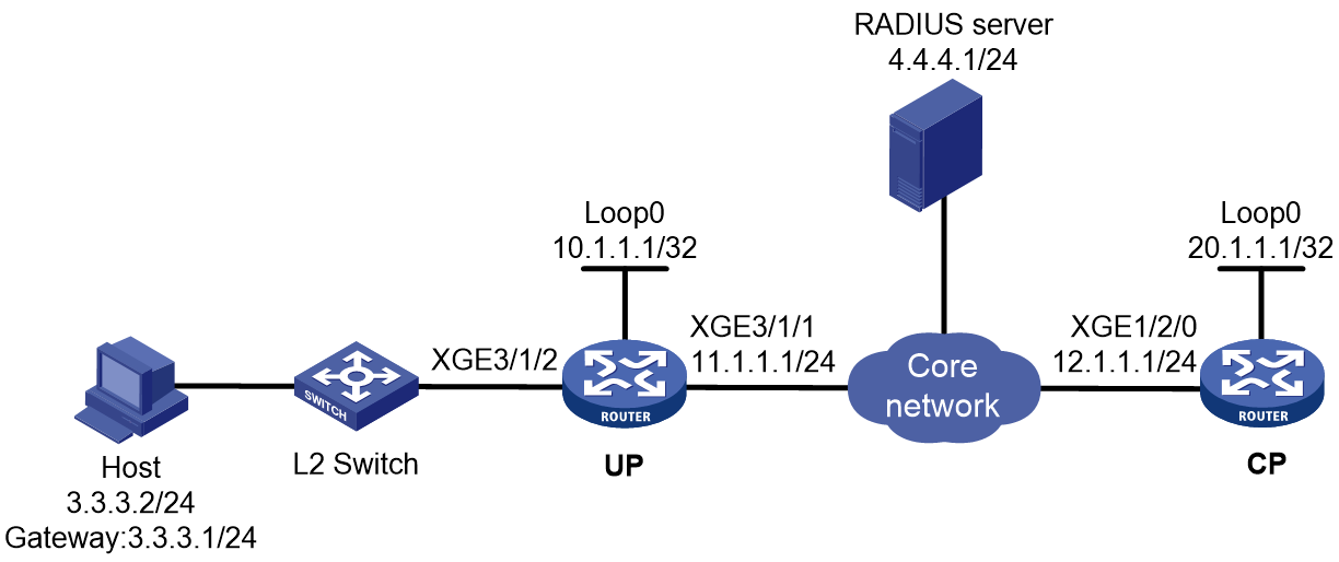
Prerequisites
Configure IP addresses for interfaces, and make sure devices can reach each other at Layer 3. (Details not shown.)
Set up the management channel, control channel, and protocol channel between the CP and UP. (Details not shown.)
Procedure
1. Configure the RADIUS server:
# Add BRAS IP address 12.1.1.1 and secret radius to the clients.conf file.
client 12.1.1.1/32 {
ipaddr = 12.1.1.1
netmask=32
secret=radius
}
# Add the username and password to the users user information file. The username is the host IP address 3.3.3.2. The password is radius.
3.3.3.2 Cleartext-Password :="radius"
2. Configure the UP:
# Configure the UP to operate in user plane mode.
<UP> system-view
[UP] work-mode user-plane
3. Configure the CP:
a. Configure a RADIUS scheme:
# Create a RADIUS scheme named rs1 and enter its view.
<CP> system-view
[CP] radius scheme rs1
# Configure primary servers and keys for authentication and accounting.
[CP-radius-rs1] primary authentication 4.4.4.1
[CP-radius-rs1] primary accounting 4.4.4.1
[CP-radius-rs1] key authentication simple radius
[CP-radius-rs1] key accounting simple radius
# Exclude the ISP name from the username sent to the RADIUS server.
[CP-radius-rs1] user-name-format without-domain
[CP-radius-rs1] quit
b. Configure the ISP domain:
# Create an ISP domain named dm1 and enter its view.
[CP] domain name dm1
# Configure ISP domain dm1 to use RADIUS scheme rs1.
[CP-isp-dm1] authentication ipoe radius-scheme rs1
[CP-isp-dm1] authorization ipoe radius-scheme rs1
[CP-isp-dm1] accounting ipoe radius-scheme rs1
[CP-isp-dm1] quit
c. Configure the DHCP server.
# Create local BAS IP address pool pool1, and specify the user gateway address. Exclude IP address 3.3.3.2 (which must be the IP address specified in static IPoE session configuration) from dynamic allocation. Bind the address pool to UP 1024.
[CP] ip pool pool1 bas local
[CP-ip-pool-pool1] gateway 3.3.3.1 24
[CP-ip-pool-pool1] forbidden-ip 3.3.3.2
[CP-ip-pool-pool1] binding up-id 1024
[CP-ip-pool-pool1] quit
# Enable the DHCP server to return a DHCP-NAK message if the client notions of their IP addresses are incorrect.
[CP] dhcp server request-ip-address check
d. Configure IPoE:
# Configure a static individual session with IP address 3.3.3.2 (which must be excluded from dynamic allocation in the IP address pool) and ISP domain dm1 on Remote-XGE 1024/3/1/2.
[CP] ip subscriber session static ip 3.3.3.2 domain dm1 interface remote-xge 1024/3/1/2
# Enable IPoE and configure Layer 2 access mode on Remote-XGE 1024/3/1/2.
[CP] interface remote-xge 1024/3/1/2
[CP–Remote-XGE1024/3/1/2] ip subscriber l2-connected enable
# Enable ARP packet initiation on Remote-XGE 1024/3/1/2.
[CP–Remote-XGE1024/3/1/2] ip subscriber initiator arp enable
# Configure plaintext password radius for authentication.
[CP–Remote-XGE1024/3/1/2] ip subscriber password plaintext radius
[CP–Remote-XGE1024/3/1/2] quit
Verifying the configuration
# Display IPoE session information to verify that the host has come online.
[CP] display access-user interface remote-xge 1024/3/1/2
UserID Interface IP address MAC address S-/C-VLAN
Username IPv6 address Access type
0x10 R-XGE1024/3/1/2 3.3.3.2 147b-1924-0206 -/-
3.3.3.2 - L2 IPoE static
Example: Configuring NS/NA packet initiation
Network configuration
As shown in Figure 185, the host accesses the BRAS as a static NS/NA user. The BRAS performs AAA for the host through the RADIUS server. This example uses the Linux Free RADIUS server.
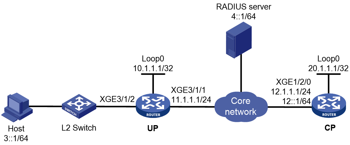
Prerequisites
Configure IP addresses for interfaces, and make sure devices can reach each other at Layer 3. (Details not shown.)
Set up the management channel, control channel, and protocol channel between the CP and UP. (Details not shown.)
Procedure
1. Configure the RADIUS server:
# Add BRAS IP address 12::1 and secret radius to the clients.conf file.
client 12::1/64 {
ipaddr6 = 12::1
netmask=64
secret=radius
}
# Add the username and password to the users user information file. The username is the host IP address 3::1 and the password is radius.
3::1 Cleartext-Password :="radius"
2. Configure the UP:
# Configure the UP to operate in user plane mode.
<UP> system-view
[UP] work-mode user-plane
3. Configure the CP:
a. Configure a RADIUS scheme:
# Create a RADIUS scheme named rs1 and enter its view.
<CP> system-view
[CP] radius scheme rs1
# Configure primary servers and keys for authentication and accounting.
[CP-radius-rs1] primary authentication ipv6 4::1
[CP-radius-rs1] primary accounting ipv6 4::1
[CP-radius-rs1] key authentication simple radius
[CP-radius-rs1] key accounting simple radius
# Exclude the ISP name from the username sent to the RADIUS server.
[CP-radius-rs1] user-name-format without-domain
[CP-radius-rs1] quit
b. Configure the ISP domain:
# Create an ISP domain named dm1 and enter its view.
[CP] domain name dm1
# Configure ISP domain dm1 to use RADIUS scheme rs1.
[CP-isp-dm1] authentication ipoe radius-scheme rs1
[CP-isp-dm1] authorization ipoe radius-scheme rs1
[CP-isp-dm1] accounting ipoe radius-scheme rs1
[CP-isp-dm1] quit
c. Configure the DHCP server:
# Create a local BAS IPv6 address pool named pool1. Specify a gateway for the address pool. Exclude IP address 10::2 (which must be the same as the user address specified in the IPoE static session) from the address pool for dynamic allocation.
[CP] ipv6 pool pool1 bas local
[CP-ipv6-pool-pool1] network 10::/64 export-route
[CP-ipv6-pool-pool1] forbidden-address 10::2
[CP-ipv6-pool-pool1] quit
d. Configure IPoE:
# Create a static session with the IPv6 address 3::1 and authentication domain dm1.
[CP] ip subscriber session static ipv6 3::1 domain dm1 interface remote-xge 1024/3/1/2
# Automatically generate a link-local address for Remote-XGE 1024/3/1/2. The IPv6 address is to be used as the gateway of users.
[CP] interface remote-xge 1024/3/1/2
[CP–Remote-XGE1024/3/1/2] ipv6 address auto link-local
# Enable IPoE and configure Layer 2 access mode on Remote-XGE 1024/3/1/2.
[CP–Remote-XGE1024/3/1/2] ip subscriber l2-connected enable
# Enable NS/NA packet initiation on Remote-XGE 1024/3/1/2.
[CP–Remote-XGE1024/3/1/2] ip subscriber initiator nsna enable
# Configure plaintext password radius for authentication.
[CP–Remote-XGE1024/3/1/2] ip subscriber password plaintext radius
[CP–Remote-XGE1024/3/1/2] quit
Verifying the configuration
# Display IPoE session information to verify that the host has come online.
[CP] display access-user interface remote-xge 1024/3/1/2
Slot 97:
UserID Interface IP address MAC address S-/C-VLAN
Username IPv6 address Access type
0x4 R-XGE1024/3/1/2 - 0010-9400-0002 -/-
3::1 3::1 L2 IPoE static
Example: Configuring unclassified-IP packet initiation for static IPoE users with IPv6 PD prefixes
Network configuration
As shown in Figure 186, Host A and Host B attached to the Layer 3 device Device use the same IPv6 address prefix (20::/64) and both obtain IPv6 addresses through stateless automatic configuration.
The BRAS uses the IPoE static user online method to enable all attached hosts to come online through IPv6 packets and performs unified authentication, accounting, rate limiting, and management for these user packets using the same IPv6 address prefix.
Use the RADIUS server as the authentication, authorization, and accounting server.
Network diagram
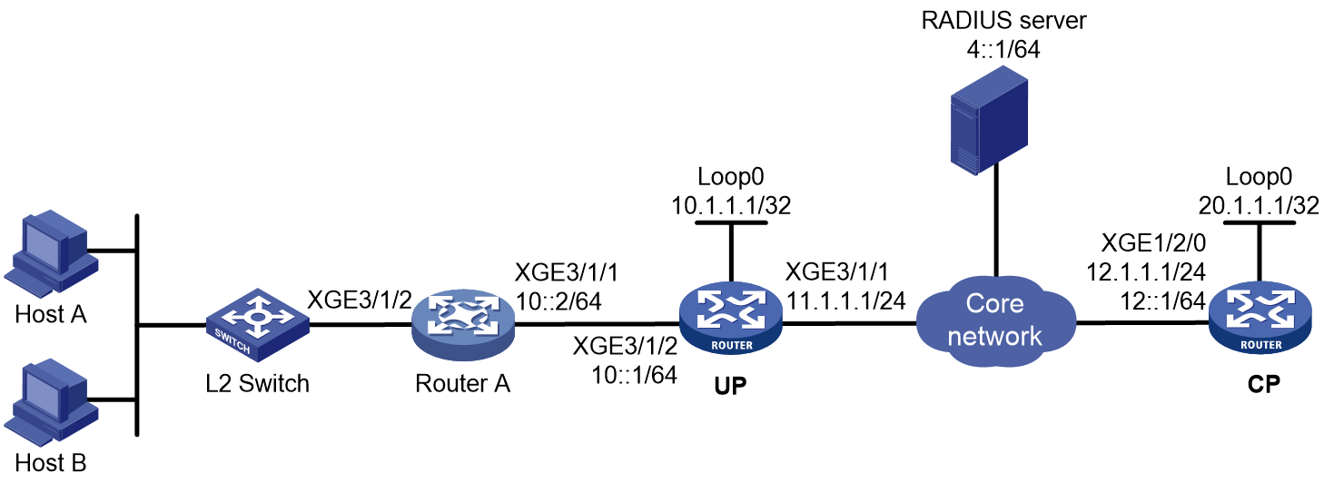
Prerequisites
Configure IP addresses for interfaces, and make sure devices can reach each other at Layer 3. (Details not shown.)
Set up the management channel, control channel, and protocol channel between the CP and UP. (Details not shown.)
Procedure
1. Configure the RADIUS server:
|
|
NOTE: This section uses the Linux Free RADIUS server as an example. |
# Configure the RADIUS client.
Add the following contents to the clients.conf file.
client 12::1/64 {
ipaddr6 = 12::1
netmask=64
secret=radius
}
The contents above configure the RADIUS client IP address as 12::1 and configure the shared key as radius.
# Configure users.
Add the following contents to the users file:
10::2 Cleartext-Password :="radius"
# Add the username and password to the users user information file. The username is 10::2 and the password is radius.
2. Configure the UP:
# Configure the UP to operate in user plane mode.
<UP> system-view
[UP] work-mode user-plane
3. Configure the CP:
a. Configure a RADIUS scheme:
# Create RADIUS scheme rs1, and enter its view.
<CP> system-view
[CP] radius scheme rs1
# Configure primary servers and keys for authentication and accounting.
[CP-radius-rs1] primary authentication ipv6 4::1
[CP-radius-rs1] primary accounting ipv6 4::1
[CP-radius-rs1] key authentication simple radius
[CP-radius-rs1] key accounting simple radius
# Exclude the ISP name from the username sent to the RADIUS server.
[CP-radius-rs1] user-name-format without-domain
[CP-radius-rs1] quit
b. Configure an ISP domain:
# Create ISP domain dm1, and enter its view.
[CP] domain name dm1
# Configure users to use RADIUS scheme rs1 for authentication, authorization, and accounting in the ISP domain.
[CP-isp-dm1] authentication ipoe radius-scheme rs1
[CP-isp-dm1] authorization ipoe radius-scheme rs1
[CP-isp-dm1] accounting ipoe radius-scheme rs1
[CP-isp-dm1] quit
c. Configure the DHCP server:
# Create a local BAS IPv6 address pool named pool1. Specify a gateway for the address pool. Exclude IP address 10::2 (which must be the same as the user address specified in the IPoE static session) from the address pool for dynamic allocation.
[CP] ipv6 pool pool1 bas local
[CP-ipv6-pool-pool1] network 10::/64 export-route
[CP-ipv6-pool-pool1] forbidden-address 10::2
[CP-ipv6-pool-pool1] quit
d. Configure IPoE:
# Configure a global IPoE static session to allow users with IPv6 address 10::2 on prefix network segment 20::/64 to come online as static users, and configure the CP to actively request users to come online.
[CP] ip subscriber session static ipv6 10::2 delegation-prefix 20:: 64 domain dm1 interface remote-xge 1024/3/1/2 request-online
# Enter the view of interface Remote-XGE 1024/3/1/2.
[CP] interface remote-xge 1024/3/1/2
# Enable IPoE and configure Layer 2 access mode.
[CP–Remote-XGE1024/3/1/2] ip subscriber l2-connected enable
# Enable unclassified-IPv6 packet initiation and NS/NA packet initiation.
[CP–Remote-XGE1024/3/1/2] ip subscriber initiator unclassified-ipv6 enable matching-user
[CP–Remote-XGE1024/3/1/2] ip subscriber initiator nsna enable
# Configure the password as radius for the IPoE individual users.
[CP–Remote-XGE1024/3/1/2] ip subscriber password plaintext radius
[CP–Remote-XGE1024/3/1/2] quit
4. Configure Router A:
# Generate an IPv6 address based on an IPv6 prefix on the interface, and assign the prefix to endpoints.
<RouterA> system-view
[RouterA] ipv6 prefix 1 20::/64
[RouterA] interface ten-gigabitethernet 3/1/2
[RouterA–Ten-GigabitEthernet3/1/2] ipv6 address 1 ::1/64
# Disable RA message suppression.
[RouterA–Ten-GigabitEthernet3/1/2] undo ipv6 nd ra halt
[RouterA–Ten-GigabitEthernet3/1/2] quit
Verifying the configuration
# After Host A sends IPv6 packets and passes authentication, execute the following command to view online information of IPoE users.
[BRAS] display access-user interface remote-xge 1024/3/1/2
Slot 97:
UserID Interface IP address MAC address S-/C-VLAN
Username IPv6 address Access type
0x4 R-XGE1024/3/1/2 - 0010-9400-0002 -/-
10::2 10::2 L2 IPoE static
Example: Configuring subnet-leased users
Network configuration
As shown in Figure 187, three hosts access the BRAS as subnet-leased users. The BRAS performs AAA for the hosts through the RADIUS server. This example uses the Linux Free RADIUS server.
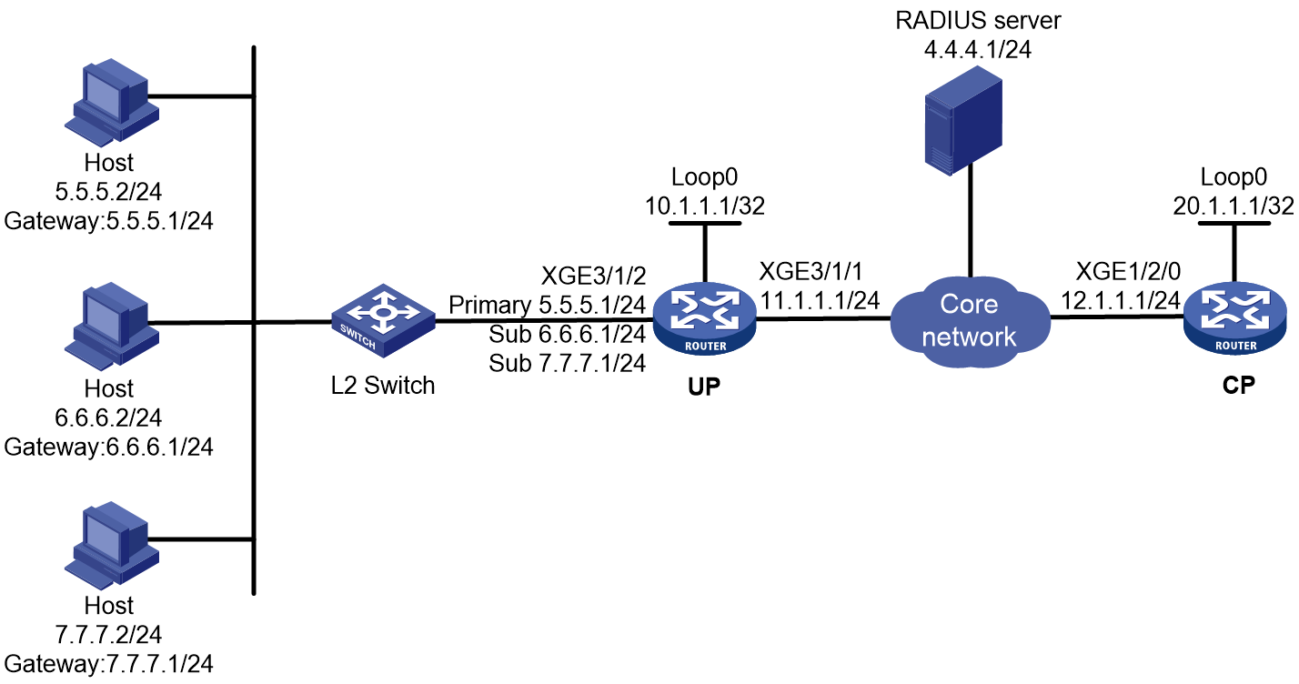
Prerequisites
Configure IP addresses for interfaces, and make sure devices can reach each other at Layer 3. (Details not shown.)
Set up the management channel, control channel, and protocol channel between the CP and UP. (Details not shown.)
Procedure
1. Configure the RADIUS server:
# Add BRAS IP address 12.1.1.1 and secret radius to the clients.conf file.
client 12.1.1.1/32 {
ipaddr = 12.1.1.1
netmask=32
secret=radius
}
# Add usernames and passwords to the users user information file. Usernames for the three subnet user groups are us1, us2, and us3. Passwords for the three subnet user groups are pw1, pw2, and pw3.
us1 Cleartext-Password :="pw1"
us2 Cleartext-Password :="pw2"
us3 Cleartext-Password :="pw3"
2. Configure the UP:
# Configure the UP to operate in user plane mode.
<UP> system-view
[UP] work-mode user-plane
3. Configure the CP:
a. Configure a RADIUS scheme:
# Create a RADIUS scheme named rs1 and enter its view.
<CP> system-view
[CP] radius scheme rs1
# Configure primary servers and keys for authentication and accounting.
[CP-radius-rs1] primary authentication 4.4.4.1
[CP-radius-rs1] primary accounting 4.4.4.1
[CP-radius-rs1] key authentication simple radius
[CP-radius-rs1] key accounting simple radius
# Exclude the ISP name from the username sent to the RADIUS server.
[CP-radius-rs1] user-name-format without-domain
[CP-radius-rs1] quit
b. Configure the ISP domain:
# Create an ISP domain named dm1 and enter its view.
[CP] domain name dm1
# Configure dm1 to use RADIUS scheme rs1.
[CP-isp-dm1] authentication ipoe radius-scheme rs1
[CP-isp-dm1] authorization ipoe radius-scheme rs1
[CP-isp-dm1] accounting ipoe radius-scheme rs1
[CP-isp-dm1] quit
c. Configure IPoE:
# Enable IPoE and configure Layer 3 access mode on Remote-XGE 1024/3/1/2.
[CP] interface remote-xge 1024/3/1/2
[CP–Remote-XGE1024/3/1/2] ip subscriber routed enable
# Configure three subnet-leased users and specify their usernames, passwords, and ISP domains.
[CP–Remote-XGE1024/3/1/2] ip subscriber subnet-leased ip 5.5.5.0 24 username us1 password plaintext pw1 domain dm1
[CP–Remote-XGE1024/3/1/2] ip subscriber subnet-leased ip 6.6.6.0 24 username us2 password plaintext pw2 domain dm1
[CP–Remote-XGE1024/3/1/2] ip subscriber subnet-leased ip 7.7.7.0 24 username us3 password plaintext pw3 domain dm1
[CP–Remote-XGE1024/3/1/2] quit
Verifying the configuration
# Display IPoE session information to verify that the host has come online.
[CP] display access-user interface remote-xge 1024/3/1/2
Slot 97:
UserID Interface IP address MAC address S-/C-VLAN
Username IPv6 address Access type
0x16 R-XGE1024/3/1/2 5.5.5.0 - -/-
us1 - L3 IPoE subnet leased
0x17 R-XGE1024/3/1/2 6.6.6.0 - -/-
us2 - L3 IPoE subnet leased
0x18 R-XGE1024/3/1/2 7.7.7.0 - -/-
us3 - L3 IPoE subnet leased
Example: Configuring an interface-leased user
Network configuration
As shown in Figure 188, three hosts access the BRAS as one interface-leased user. The BRAS performs AAA for the hosts through the RADIUS server. This example uses the Linux Free RADIUS server.
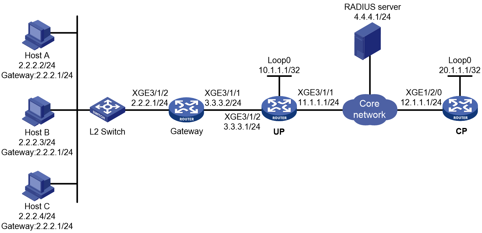
Prerequisites
Configure IP addresses for interfaces, and make sure devices can reach each other at Layer 3. (Details not shown.)
Set up the management channel, control channel, and protocol channel between the CP and UP. (Details not shown.)
Procedure
1. Configure the RADIUS server:
# Add the BRAS IP address 12.1.1.1 and the secret radius to the clients.conf file.
client 12.1.1.1/32 {
ipaddr = 12.1.1.1
netmask=32
secret=radius
}
# Add host username and password to the users user information file. The username is us1 and the password is pw1.
us1 Cleartext-Password :="pw1"
2. Configure the UP:
# Configure the UP to operate in user plane mode.
<UP> system-view
[UP] work-mode user-plane
3. Configure the CP:
a. Configure a RADIUS scheme:
# Create a RADIUS scheme named rs1 and enter its view.
<CP> system-view
[CP] radius scheme rs1
# Configure primary servers and keys for authentication and accounting.
[CP-radius-rs1] primary authentication 4.4.4.1
[CP-radius-rs1] primary accounting 4.4.4.1
[CP-radius-rs1] key authentication simple radius
[CP-radius-rs1] key accounting simple radius
# Exclude the ISP name from the username sent to the RADIUS server.
[CP-radius-rs1] user-name-format without-domain
[CP-radius-rs1] quit
b. Configure the ISP domain:
# Create an ISP domain named dm1 and enter its view.
[CP] domain name dm1
# Configure dm1 to use RADIUS scheme rs1.
[CP-isp-dm1] authentication ipoe radius-scheme rs1
[CP-isp-dm1] authorization ipoe radius-scheme rs1
[CP-isp-dm1] accounting ipoe radius-scheme rs1
[CP-isp-dm1] quit
c. Configure IPoE:
# Enable IPoE and configure Layer 3 access mode on Remote-XGE 1024/3/1/2.
[CP] interface remote-xge 1024/3/1/2
[CP–Remote-XGE1024/3/1/2] ip subscriber routed enable
# Configure the interface-leased user and specify its username, password, and ISP domain.
[CP–Remote-XGE1024/3/1/2] ip subscriber interface-leased username us1 password plaintext pw1 domain dm1
[CP–Remote-XGE1024/3/1/2] quit
Verifying the configuration
# Display IPoE session information to verify that the host has come online.
[CP] display access-user interface remote-xge 1024/3/1/2
Slot 97:
UserID Interface IP address MAC address S-/C-VLAN
Username IPv6 address Access type
0xec R-XGE1024/3/1/2 - - -/-
us1 - L3 IPoE interface leased
Example: Configuring IPoE common Web authentication for static individual users
Network configuration
As shown in Figure 189, the host accesses the BRAS through a Layer 2 switch. A server installed with H3C IMC acts as the RADIUS server, the portal authentication server, and the portal Web server. This example uses IMC PLAT 7.1(E0303), IMC UAM 7.1(E0305), and IMC EIP 7.1(E0305). The FTP server is an internal network server.
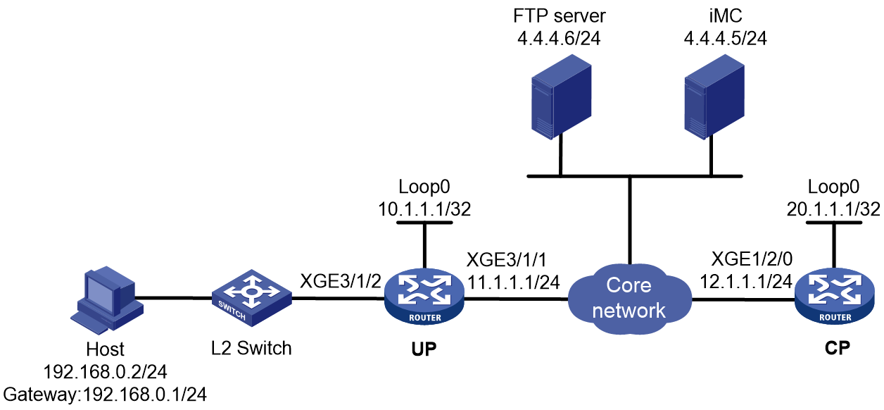
Prerequisites
Configure IP addresses for interfaces, and make sure devices can reach each other at Layer 3. (Details not shown.)
Set up the management channel, control channel, and protocol channel between the CP and UP. (Details not shown.)
Procedure
1. Configure the UP:
a. Configure the UP to operate in user plane mode.
<UP> system-view
[UP] work-mode user-plane
b. Specify 11111 as the HTTPS redirect listening port number. Make sure the port number is not used by any other service. To see the TCP port numbers used by other services, execute the display tcp command.
[UP] http-redirect https-port 11111
c. Create a local user group named pre.
[UP] user-group pre
New user group added.
[UP-ugroup-pre] quit
d. Configure ACLs for preauthentication:
# Create an IPv4 advanced ACL named web_permit. Configure a rule to permit all packets destined for the portal server from users in user group pre.
[UP] acl advanced name web_permit
[UP-acl-ipv4-adv-web_permit] rule 0 permit ip destination 4.4.4.5 0 user-group pre
[UP-acl-ipv4-adv-web_permit] quit
# Create an IPv4 advanced ACL named neiwang. Configure a rule to permit all packets destined for the internal network server from users in user group pre.
[UP] acl advanced name neiwang
[UP-acl-ipv4-adv-neiwang] rule 0 permit ip destination 4.4.4.6 0 user-group pre
[UP-acl-ipv4-adv-neiwang] quit
# Create an IPv4 advanced ACL named web_http. Configure a rule to permit TCP packets with the destination port 80 (HTTP packets) from users in user group pre.
[UP] acl advanced name web_http
[UP-acl-ipv4-adv-web_http] rule 0 permit tcp destination-port eq www user-group pre
[UP-acl-ipv4-adv-web_http] quit
# Create an IPv4 advanced ACL named web_https, and configure a rule to permit TCP packets with the destination port 443 (HTTPS packets) from users in user group pre.
[UP] acl advanced name web_https
[UP-acl-ipv4-adv-web_https] rule 0 permit tcp destination-port eq 443 user-group pre
[UP-acl-ipv4-adv-web_https] quit
# Create an IPv4 advanced ACL named ip, and configure a rule to permit IP packets from users in user group pre.
[UP] acl advanced name ip
[UP-acl-ipv4-adv-ip] rule 0 permit ip user-group pre
[UP-acl-ipv4-adv-ip] quit
# Create an IPv4 advanced ACL named neiwang_out, and configure a rule to permit IP packets from the internal network server in user group pre.
[UP] acl advanced name neiwang_out
[UP-acl-ipv4-adv-neiwang_out] rule 0 permit ip source 4.4.4.4 0 user-group pre
[UP-acl-ipv4-adv-neiwang_out] quit
# Create an IPv4 advanced ACL named web_out, and configure a rule to permit IP packets from the portal server in user group pre.
[UP] acl advanced name web_out
[UP-acl-ipv4-adv-web_out] rule 0 permit ip source 4.4.4.5 0 user-group pre
[UP-acl-ipv4-adv-web_out] quit
e. Configure QoS traffic classes for preauthentication users:
# Create the traffic class web_permit and specify ACL web_permit as the match criterion.
[UP] traffic classifier web_permit operator and
[UP-classifier-web_permit] if-match acl name web_permit
[UP-classifier-web_permit] quit
# Create the traffic class neiwang and specify ACL neiwang as the match criterion.
[UP] traffic classifier neiwang operator and
[UP-classifier-neiwang] if-match acl name neiwang
[UP-classifier-neiwang] quit
# Create the traffic class web_http and specify ACL web_http as the match criterion.
[UP] traffic classifier web_http operator and
[UP-classifier-web_http] if-match acl name web_http
[UP-classifier-web_http] quit
# Create the traffic class web_https and specify ACL web_https as the match criterion.
[UP] traffic classifier web_https operator and
[UP-classifier-web_https] if-match acl name web_https
[UP-classifier-web_https] quit
# Create the traffic class web_deny and specify ACL ip as the match criterion.
[UP] traffic classifier web_deny operator and
[UP-classifier-web_deny] if-match acl name ip
[UP-classifier-web_deny] quit
# Create the traffic class neiwang_out and specify ACL neiwang_out as the match criterion.
[UP] traffic classifier neiwang_out operator and
[UP-classifier-neiwang_out] if-match acl name neiwang_out
[UP-classifier-neiwang_out] quit
# Create the traffic class web_out and specify ACL web_out as the match criterion.
[UP] traffic classifier web_out operator and
[UP-classifier-web_out] if-match acl name web_out
[UP-classifier-web_out] quit
f. Configure QoS traffic behaviors:
# Configure the traffic behavior web_permit to permit traffic to pass through without rate limiting or accounting.
[UP] traffic behavior web_permit
[UP-behavior-web_permit] filter permit
[UP-behavior-web_permit] free account
[UP-behavior-web_permit] quit
# Configure the traffic behavior neiwang to permit traffic to pass through.
[UP] traffic behavior neiwang
[UP-behavior-neiwang] filter permit
[UP-behavior-neiwang] quit
# Configure the traffic behavior web_http to redirect HTTP packets to the CPU.
[UP] traffic behavior web_http
[UP-behavior-web_http] redirect http-to-cpu
[UP-behavior-web_http] quit
# Configure the traffic behavior web_https to redirect HTTPS packets to the CPU.
[UP] traffic behavior web_https
[UP-behavior-web_https] redirect https-to-cpu
[UP-behavior-web_https] quit
# Configure the traffic behavior web_deny to deny traffic.
[UP] traffic behavior web_deny
[UP-behavior-web_deny] filter deny
[UP-behavior-web_deny] free account
[UP-behavior-web_deny] quit
# Configure the traffic behavior neiwang_out to permit traffic to pass through.
[UP] traffic behavior neiwang_out
[UP-behavior-neiwang_out] filter permit
[UP-behavior-neiwang_out] quit
# Configure the traffic behavior web_out to permit traffic without rate limiting or traffic accounting.
[UP] traffic behavior web_out
[UP-behavior-web_out] filter permit
[UP-behavior-web_out] free account
[UP-behavior-web_out] quit
g. Configure the QoS policies:
# Create a QoS policy named web.
[UP] qos policy web
# Associate the traffic class web_permit with the traffic behavior web_permit.
[UP-qospolicy-web] classifier web_permit behavior web_permit
# Associate the traffic class neiwang with the traffic behavior neiwang.
[UP-qospolicy-web] classifier neiwang behavior neiwang
# Associate the traffic class web_http with the traffic behavior web_http.
[UP-qospolicy-web] classifier web_http behavior web_http
# Associate the traffic class web_https with the traffic behavior web_https.
[UP-qospolicy-web] classifier web_https behavior web_https
# Associate the traffic class web_deny with the traffic behavior web_deny.
[UP-qospolicy-web] classifier web_deny behavior web_deny
[UP-qospolicy-web] quit
# Configure a QoS policy named out.
[UP] qos policy out
# Associate the traffic class web_out with the traffic behavior web_out. Associate the traffic class neiwang_out with the traffic behavior neiwang_out. Associate the traffic class web_deny with the traffic behavior web_deny.
[UP-qospolicy-out] classifier web_out behavior web_out
[UP-qospolicy-out] classifier neiwang_out behavior neiwang_out
[UP-qospolicy-out] classifier web_deny behavior web_deny
[UP-qospolicy-out] quit
h. Apply the QoS policies:
# Apply the QoS Policy web to the inbound traffic globally. To identify whether the QoS policy takes effect, execute the display qos policy global inbound command.
[UP] qos apply policy web global inbound
# Apply the QoS Policy out to the outbound traffic globally. To identify whether the QoS policy takes effect, execute the display qos policy global outbound command.
[UP] qos apply policy out global outbound
2. Configure the CP:
a. Configure the IP address of the portal authentication server newpt as 4.4.4.5 and the plaintext key 123456.
[CP] portal server newpt
[CP-portal-server-newpt] ip 4.4.4.5 key simple 123456
[CP-portal-server-newpt] quit
b. Configure the CP to get user access information from ARP and ND entries.
[CP] portal access-info trust arp
[CP] portal access-info trust nd
c. Create a local user group named pre.
[CP] user-group pre
New user group added.
[CP-ugroup-pre] quit
d. Configure a RADIUS scheme:
# Create a RADIUS scheme named rs1 and enter its view.
[CP] radius scheme rs1
# Configure primary servers and keys for authentication and accounting.
[CP-radius-rs1] primary authentication 4.4.4.5
[CP-radius-rs1] primary accounting 4.4.4.5
[CP-radius-rs1] key authentication simple radius
[CP-radius-rs1] key accounting simple radius
# Exclude the ISP name from the username sent to the RADIUS server.
[CP-radius-rs1] user-name-format without-domain
[CP-radius-rs1] quit
e. Configure the preauthentication ISP domain and Web authentication ISP domain:
# Configure the ISP domain dm1 for IPoE user preauthentication.
[CP] domain name dm1
[CP-isp-dm1] authentication ipoe none
[CP-isp-dm1] authorization ipoe none
[CP-isp-dm1] accounting ipoe none
# Configure the authorized user group in ISP domain dm1.
[CP-isp-dm1] authorization-attribute user-group pre
# Configure the Web authentication page URL and Web server IP address in ISP domain dm1.
[CP-isp-dm1] web-server url http://4.4.4.5:8080/portal/
[CP-isp-dm1] web-server ip 4.4.4.5
[CP-isp-dm1] quit
# Configure the ISP domain dm2 for IPoE user Web authentication.
[CP] domain name dm2
[CP-isp-dm2] authentication ipoe radius-scheme rs1
[CP-isp-dm2] authorization ipoe radius-scheme rs1
[CP-isp-dm2] accounting ipoe radius-scheme rs1
[CP-isp-dm2] quit
f. Configure the DHCP server.
# Create local BAS IP address pool pool1, and specify the user gateway address. Exclude IP address 192.168.0.2 (which must be the IP address specified in static IPoE session configuration) from dynamic allocation. Bind the address pool to UP 1024.
[CP] ip pool pool1 bas local
[CP-ip-pool-pool1] gateway 192.168.0.1 24
[CP-ip-pool-pool1] forbidden-ip 192.168.0.2
[CP-ip-pool-pool1] binding up-id 1024
[CP-ip-pool-pool1] quit
# Enable the DHCP server to return a DHCP-NAK message if the client notions of their IP addresses are incorrect.
[CP] dhcp server request-ip-address check
g. Configure IPoE:
# Enable IPoE and configure Layer 2 access mode on Remote-XGE 1024/3/1/2.
[CP] interface remote-xge 1024/3/1/2
[CP–Remote-XGE1024/3/1/2] ip subscriber l2-connected enable
# Enable unclassified-IPv4 packet initiation.
[CP–Remote-XGE1024/3/1/2] ip subscriber initiator unclassified-ip enable matching-user
# Configure an IPoE static user with IP address 192.168.0.2, which must be excluded from dynamic allocation in the IP address pool.
[CP–Remote-XGE1024/3/1/2] ip subscriber session static ip 192.168.0.2
# Configure Web authentication for IPoE users on Remote-XGE 1024/3/1/2.
[CP–Remote-XGE1024/3/1/2] ip subscriber authentication-method web
The operation may cut all users on this interface. Continue?[Y/N]:y
# Configure the ISP domain dm1 for preauthentication and the ISP domain dm2 for Web authentication on Remote-XGE 1024/3/1/2.
[CP–Remote-XGE1024/3/1/2] ip subscriber pre-auth domain dm1
[CP–Remote-XGE1024/3/1/2] ip subscriber web-auth domain dm2
[CP–Remote-XGE1024/3/1/2] quit
3. Configure the RADIUS server:
a. Configure the access device:
- Log in to the IMC platform and click the User tab.
- Select User Access Policy > Access Device Management > Access Device from the navigation tree to open the access device configuration page.
- Click Add to open the page as shown in Figure 190.
- Enter the shared key radius.
- Use the default settings for other parameters.
Figure 190 Adding an access device

- Click Add Manually in the Device List area to open the page.
- Enter the access device's IP address 12.1.1.1.
- Click OK.
a. Add an access policy:
- Select User Access Policy > Access Policy from the navigation tree to open the access policy page.
- Click Add to open the page as shown in Figure 191.
- Enter the access policy name AccessPolicy.
- Use the default settings for other parameters.
Figure 191 Adding an access policy
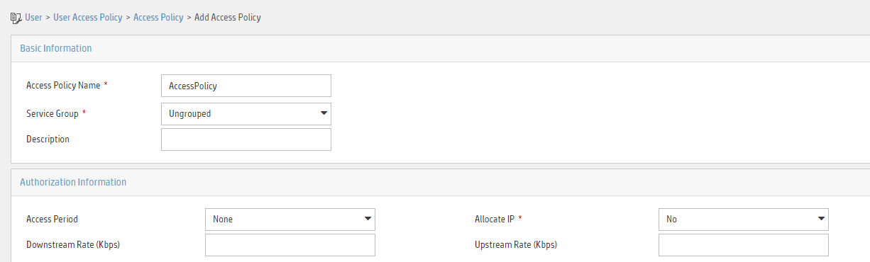
a. Add an access service:
- Select User Access Policy > Access Service from the navigation tree to open the access service page.
- Click Add to open the page as shown in Figure 192.
- Enter the service name IPoE_Server.
- Select AccessPolicy from the default access policy list.
- Use the default settings for other parameters.
Figure 192 Adding an access service

a. Add a user:
- Select User Management > Add User from the navigation tree to open the adding user page, as shown in Figure 193.
- Enter the username IPoE_Web001 and the user ID 001.
- Click OK.

a. Add an access user:
- Select Access User > All Access Users from the navigation tree to open the access user page.
- Click Add to open the page as shown in Figure 194.
- Select IPoE_Web001 for the username.
- Enter the account name user1.
- Enter the password pass1.
- Select the access service IPoE_Server.
Figure 194 Adding an access user

4. Configure the portal server:
a. Configure the portal homepage:
- Select User Access Policy > Portal Service > Server from the navigation tree to open the portal server configuration page, as shown in Figure 195.
- Click OK.
Figure 195 Portal server configuration page

a. Configure portal authentication source IP address range:
- Select User Access Policy > Portal Service > IP Group from the navigation tree to open the portal IP address group configuration page.
- Click Add to open the page as shown in Figure 196.
- Enter the IP group name IPoE_Web_User.
- Enter the start IP address (192.168.0.1) and end IP address (192.168.0.255) of the IP group. Make sure the host IP address is in the IP group.
- Click OK.
Figure 196 Adding an IP address group

a. Add a portal device:
- Select User Access Policy > Portal Service > Device from the navigation tree to open the portal device configuration page.
- Click Add.
- Enter the device name NAS.
- Enter the IP address of the portal packets' outgoing interface Ten-GigabitEthernet 3/1/2 (12.1.1.1).
- Enter the key 123456.
- Select Directly Connect for access method.
- Click OK.
b. Associate the portal device with the IP address group:
- Click the icon in the Port Group Information Management column of device NAS to open the port group configuration page, as shown in Figure 197.
- Click Add to open the page as shown in Figure 198.
- Enter the port group name group.
- Select the configured IP address group IPoE_Web_User. Make sure the IP address used by the user to access the network is within this IP address group.
- Click OK.

Figure 198 Port group configuration
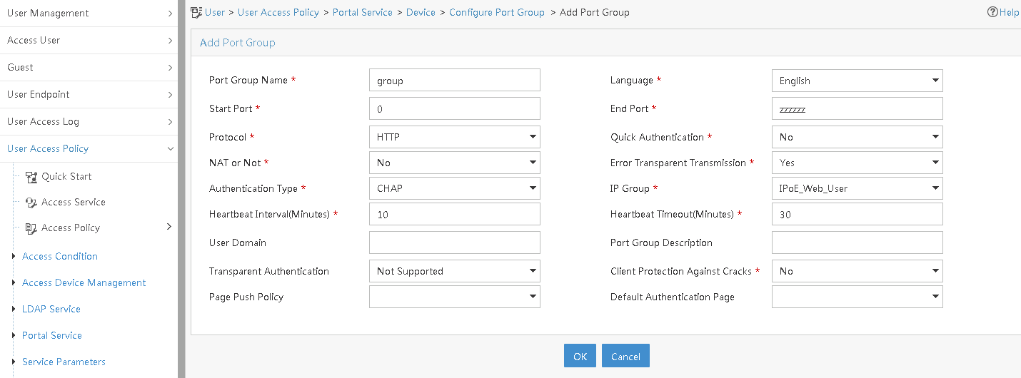
Verifying the configuration
# Display IPoE session information to verify that the host has passed preauthentication.
[CP] display access-user auth-type pre-auth interface remote-xge 1024/3/1/2
Slot 97:
UserID Interface IP address MAC address S-/C-VLAN
Username IPv6 address Access type
0x33d R-XGE1024/3/1/2 192.168.0.2 0015-e947-f4d4 -/-
192.168.0.2 - L2 IPoE static
As shown in Figure 199, the Web login page opens after preauthentication. Enter the username and password on the page.
# Display IPoE session information to verify that the host has passed Web authentication and come online.
[CP] display access-user auth-type web-auth interface remote-xge 1024/3/1/2
Slot 97:
UserID Interface IP address MAC address S-/C-VLAN
Username IPv6 address Access type
0x33d R-XGE1024/3/1/2 192.168.0.2 0015-e947-f4d4 -/-
user1@dm2 - Web auth
Example: Configuring IPoE common Web authentication for DHCPv4 users (assigning a remote BAS IP address pool)
Network configuration
As shown in Figure 200, the host accesses the BRAS as a DHCP client through a Layer 2 device. It obtains configuration information from the DHCP server through the BRAS. The BRAS performs AAA for the host through the RADIUS server. A server installed with H3C IMC acts as the RADIUS server, the portal authentication server, and the portal Web server. The FTP server is an internal network server.

Prerequisites
Configure IP addresses for interfaces, and make sure devices can reach each other at Layer 3. (Details not shown.)
Set up the management channel, control channel, and protocol channel between the CP and UP. (Details not shown.)
Procedure
1. Configure the DHCP server:
# Enable DHCP.
<DHCP-server> system-view
[DHCP-server] dhcp enable
# Enable the DHCP server to return a DHCP-NAK message if the client notions of their IP addresses are incorrect.
[DHCP-server] dhcp server request-ip-address check
# Create an IP address pool named pool1 and enter its view.
[DHCP-server] ip pool pool1
# Specify primary subnet 192.168.0.0/24 for dynamic allocation in address pool pool1.
[DHCP-server-ip-pool-pool1] network 192.168.0.0 24
# Specify gateway address 192.168.0.1 in address pool pool1.
[DHCP-server-ip-pool-pool1] gateway-list 192.168.0.1
# Specify DNS server address 8.8.8.8 in address pool pool1.
[DHCP-server-ip-pool-pool1] dns-list 8.8.8.8
# Exclude IP address 192.168.0.1 from dynamic allocation in address pool pool1.
[DHCP-server-ip-pool-pool1] forbidden-ip 192.168.0.1
[DHCP-server-ip-pool-pool1] quit
# Configure the default route to the CP.
[DHCP-server] ip route-static 0.0.0.0 0 12.1.1.1
2. Configure the UP:
a. Configure the UP to operate in user plane mode.
<UP> system-view
[UP] work-mode user-plane
b. Specify 11111 as the HTTPS redirect listening port number. Make sure the port number is not used by any other service. To see the TCP port numbers used by other services, execute the display tcp command.
[UP] http-redirect https-port 11111
c. Create a local user group named pre.
[UP] user-group pre
New user group added.
[UP-ugroup-pre] quit
d. Configure ACLs for preauthentication:
# Create an IPv4 advanced ACL named web_permit. Configure a rule to permit all packets destined for the portal server from users in user group pre.
[UP] acl advanced name web_permit
[UP-acl-ipv4-adv-web_permit] rule 0 permit ip destination 4.4.4.5 0 user-group pre
[UP-acl-ipv4-adv-web_permit] quit
# Create an IPv4 advanced ACL named neiwang. Configure a rule to permit all packets destined for the internal network server from users in user group pre.
[UP] acl advanced name neiwang
[UP-acl-ipv4-adv-neiwang] rule 0 permit ip destination 4.4.4.6 0 user-group pre
[UP-acl-ipv4-adv-neiwang] quit
# Create an IPv4 advanced ACL named web_http. Configure a rule to permit TCP packets with the destination port 80 (HTTP packets) from users in user group pre.
[UP] acl advanced name web_http
[UP-acl-ipv4-adv-web_http] rule 0 permit tcp destination-port eq www user-group pre
[UP-acl-ipv4-adv-web_http] quit
# Create an IPv4 advanced ACL named web_https, and configure a rule to permit TCP packets with the destination port 443 (HTTPS packets) from users in user group pre.
[UP] acl advanced name web_https
[UP-acl-ipv4-adv-web_https] rule 0 permit tcp destination-port eq 443 user-group pre
[UP-acl-ipv4-adv-web_https] quit
# Create an IPv4 advanced ACL named ip, and configure a rule to permit IP packets from users in user group pre.
[UP] acl advanced name ip
[UP-acl-ipv4-adv-ip] rule 0 permit ip user-group pre
[UP-acl-ipv4-adv-ip] quit
# Create an IPv4 advanced ACL named neiwang_out, and configure a rule to permit IP packets from the internal network server in user group pre.
[UP] acl advanced name neiwang_out
[UP-acl-ipv4-adv-neiwang_out] rule 0 permit ip source 4.4.4.4 0 user-group pre
[UP-acl-ipv4-adv-neiwang_out] quit
# Create an IPv4 advanced ACL named web_out, and configure a rule to permit IP packets from the portal server in user group pre.
[UP] acl advanced name web_out
[UP-acl-ipv4-adv-web_out] rule 0 permit ip source 4.4.4.5 0 user-group pre
[UP-acl-ipv4-adv-web_out] quit
e. Configure QoS traffic classes for preauthentication users:
# Create the traffic class web_permit and specify ACL web_permit as the match criterion.
[UP] traffic classifier web_permit operator and
[UP-classifier-web_permit] if-match acl name web_permit
[UP-classifier-web_permit] quit
# Create the traffic class neiwang and specify ACL neiwang as the match criterion.
[UP] traffic classifier neiwang operator and
[UP-classifier-neiwang] if-match acl name neiwang
[UP-classifier-neiwang] quit
# Create the traffic class web_http and specify ACL web_http as the match criterion.
[UP] traffic classifier web_http operator and
[UP-classifier-web_http] if-match acl name web_http
[UP-classifier-web_http] quit
# Create the traffic class web_https and specify ACL web_https as the match criterion.
[UP] traffic classifier web_https operator and
[UP-classifier-web_https] if-match acl name web_https
[UP-classifier-web_https] quit
# Create the traffic class web_deny and specify ACL ip as the match criterion.
[UP] traffic classifier web_deny operator and
[UP-classifier-web_deny] if-match acl name ip
[UP-classifier-web_deny] quit
# Create the traffic class neiwang_out and specify ACL neiwang_out as the match criterion.
[UP] traffic classifier neiwang_out operator and
[UP-classifier-neiwang_out] if-match acl name neiwang_out
[UP-classifier-neiwang_out] quit
# Create the traffic class web_out and specify ACL web_out as the match criterion.
[UP] traffic classifier web_out operator and
[UP-classifier-web_out] if-match acl name web_out
[UP-classifier-web_out] quit
f. Configure QoS traffic behaviors:
# Configure the traffic behavior web_permit to permit traffic to pass through without rate limiting or accounting.
[UP] traffic behavior web_permit
[UP-behavior-web_permit] filter permit
[UP-behavior-web_permit] free account
[UP-behavior-web_permit] quit
# Configure the traffic behavior neiwang to permit traffic to pass through.
[UP] traffic behavior neiwang
[UP-behavior-neiwang] filter permit
[UP-behavior-neiwang] quit
# Configure the traffic behavior web_http to redirect HTTP packets to the CPU.
[UP] traffic behavior web_http
[UP-behavior-web_http] redirect http-to-cpu
[UP-behavior-web_http] quit
# Configure the traffic behavior web_https to redirect HTTPS packets to the CPU.
[UP] traffic behavior web_https
[UP-behavior-web_https] redirect https-to-cpu
[UP-behavior-web_https] quit
# Configure the traffic behavior web_deny to deny traffic.
[UP] traffic behavior web_deny
[UP-behavior-web_deny] filter deny
[UP-behavior-web_deny] free account
[UP-behavior-web_deny] quit
# Configure the traffic behavior neiwang_out to permit traffic to pass through.
[UP] traffic behavior neiwang_out
[UP-behavior-neiwang_out] filter permit
[UP-behavior-neiwang_out] quit
# Configure the traffic behavior web_out to permit traffic without rate limiting or traffic accounting.
[UP] traffic behavior web_out
[UP-behavior-web_out] filter permit
[UP-behavior-web_out] free account
[UP-behavior-web_out] quit
g. Configure the QoS policies:
# Create a QoS policy named web.
[UP] qos policy web
# Associate the traffic class web_permit with the traffic behavior web_permit.
[UP-qospolicy-web] classifier web_permit behavior web_permit
# Associate the traffic class neiwang with the traffic behavior neiwang.
[UP-qospolicy-web] classifier neiwang behavior neiwang
# Associate the traffic class web_http with the traffic behavior web_http.
[UP-qospolicy-web] classifier web_http behavior web_http
# Associate the traffic class web_https with the traffic behavior web_https.
[UP-qospolicy-web] classifier web_https behavior web_https
# Associate the traffic class web_deny with the traffic behavior web_deny.
[UP-qospolicy-web] classifier web_deny behavior web_deny
[UP-qospolicy-web] quit
# Configure a QoS policy named out.
[UP] qos policy out
# Associate the traffic class web_out with the traffic behavior web_out. Associate the traffic class neiwang_out with the traffic behavior neiwang_out. Associate the traffic class web_deny with the traffic behavior web_deny.
[UP-qospolicy-out] classifier web_out behavior web_out
[UP-qospolicy-out] classifier neiwang_out behavior neiwang_out
[UP-qospolicy-out] classifier web_deny behavior web_deny
[UP-qospolicy-out] quit
h. Apply the QoS policies:
# Apply the QoS Policy web to the inbound traffic globally. To identify whether the QoS policy takes effect, execute the display qos policy global inbound command.
[UP] qos apply policy web global inbound
# Apply the QoS Policy out to the outbound traffic globally. To identify whether the QoS policy takes effect, execute the display qos policy global outbound command.
[UP] qos apply policy out global outbound
3. Configure the CP:
a. Configure the DHCP relay agent:
# Enable the DHCP relay agent on Remote-XGE 1024/3/1/2.
<CP> system-view
[CP] interface remote-xge 1024/3/1/2
[CP–Remote-XGE1024/3/1/2] dhcp select relay
[CP–Remote-XGE1024/3/1/2] quit
# Create a remote BAS IP address pool named pool1.
[CP] ip pool pool1 bas remote
# Specify gateway address 192.168.0.1 in address pool pool1.
[CP-ip-pool-pool1] gateway 192.168.0.1 24
# Exclude IP address 192.168.0.1 from dynamic allocation in address pool pool1.
[CP-ip-pool-pool1] forbidden-ip 192.168.0.1
# Specify DHCP server 4.4.4.3 in address pool pool1, and bind the address pool to UP 1024.
[CP-ip-pool-pool1] remote-server 4.4.4.3
[CP-ip-pool-pool1] binding up-id 1024
[CP-ip-pool-pool1] quit
b. Configure the IP address of the portal authentication server newpt as 4.4.4.5 and the plaintext key 123456.
[CP] portal server newpt
[CP-portal-server-newpt] ip 4.4.4.5 key simple 123456
[CP-portal-server-newpt] quit
c. Configure the CP to get user access information from ARP and ND entries.
[CP] portal access-info trust arp
[CP] portal access-info trust nd
d. Create a local user group named pre.
[CP] user-group pre
New user group added.
[CP-ugroup-pre] quit
e. Configure a RADIUS scheme:
# Create a RADIUS scheme named rs1 and enter its view.
[CP] radius scheme rs1
# Configure primary servers and keys for authentication and accounting.
[CP-radius-rs1] primary authentication 4.4.4.5
[CP-radius-rs1] primary accounting 4.4.4.5
[CP-radius-rs1] key authentication simple radius
[CP-radius-rs1] key accounting simple radius
# Exclude the ISP name from the username sent to the RADIUS server.
[CP-radius-rs1] user-name-format without-domain
[CP-radius-rs1] quit
f. Configure the preauthentication ISP domain and Web authentication ISP domain:
# Configure the ISP domain dm1 for IPoE user preauthentication.
[CP] domain name dm1
[CP-isp-dm1] authentication ipoe none
[CP-isp-dm1] authorization ipoe none
[CP-isp-dm1] accounting ipoe none
# Configure the authorized IP address pool and user group in preauthentication ISP domain dm1.
[CP-isp-dm1] authorization-attribute user-group pre
[CP-isp-dm1] authorization-attribute ip-pool pool1
# Configure the Web authentication page URL and Web server IP address in ISP domain dm1.
[CP-isp-dm1] web-server url http://4.4.4.5:8080/portal/
[CP-isp-dm1] web-server ip 4.4.4.5
[CP-isp-dm1] quit
# Configure the ISP domain dm2 for IPoE user Web authentication.
[CP] domain name dm2
[CP-isp-dm2] authentication ipoe radius-scheme rs1
[CP-isp-dm2] authorization ipoe radius-scheme rs1
[CP-isp-dm2] accounting ipoe radius-scheme rs1
[CP-isp-dm2] quit
g. Configure IPoE:
# Enable IPoE and configure Layer 2 access mode on Remote-XGE 1024/3/1/2.
[CP] interface remote-xge 1024/3/1/2
[CP–Remote-XGE1024/3/1/2] ip subscriber l2-connected enable
# Configure Web authentication for IPoE users on Remote-XGE 1024/3/1/2.
[CP–Remote-XGE1024/3/1/2] ip subscriber authentication-method web
The operation may cut all users on this interface. Continue?[Y/N]:y
# Configure the ISP domain dm1 for preauthentication and the ISP domain dm2 for Web authentication on Remote-XGE 1024/3/1/2.
[CP–Remote-XGE1024/3/1/2] ip subscriber pre-auth domain dm1
[CP–Remote-XGE1024/3/1/2] ip subscriber web-auth domain dm2
[CP–Remote-XGE1024/3/1/2] quit
4. Configure the RADIUS server:
a. Configure the access device:
- Log in to the IMC platform and click the User tab.
- Select User Access Policy > Access Device Management > Access Device from the navigation tree to open the access device configuration page.
- Click Add to open the page as shown in Figure 201.
- Enter the shared key radius.
- Use the default settings for other parameters.
Figure 201 Adding an access device

- Click Add Manually in the Device List.
- Enter the access device's IP address 12.1.1.1.
- Click OK.
a. Add an access policy:
- Select User Access Policy > Access Policy from the navigation tree to open the access policy page.
- Click Add to open the page as shown in Figure 202.
- Enter the access policy name AccessPolicy.
- Use the default settings for other parameters.
Figure 202 Adding an access policy

a. Add an access service:
- Select User Access Policy > Access Service from the navigation tree to open the access service page.
- Click Add to open the page as shown in Figure 203.
- Enter the service name IPoE_Server.
- Select AccessPolicy from the default access policy list.
- Use the default settings for other parameters.
Figure 203 Adding an access service

a. Add a user:
- Select User Management > Add User from the navigation tree to open the adding user page, as shown in Figure 204.
- Enter the username IPoE_Web001 and the user ID 001.
- Click OK.

a. Add an access user:
- Select Access User > All Access Users from the navigation tree to open the access user page.
- Click Add to open the page as shown in Figure 205.
- Select IPoE_Web001 for the username.
- Enter the account name user1.
- Enter the password pass1.
- Select the access service IPoE_Server.
Figure 205 Adding an access user

5. Configure the portal server:
a. Configure the portal homepage:
- Select User Access Policy > Portal Service > Server from the navigation tree to open the portal server configuration page, as shown in Figure 206.
- Click OK.
Figure 206 Portal server configuration page

a. Configure portal authentication source IP address range:
- Select User Access Policy > Portal Service > IP Group from the navigation tree to open the portal IP address group configuration page.
- Click Add to open the page as shown in Figure 207.
- Enter the IP group name IPoE_Web_User.
- Enter the start IP address (192.168.0.1) and end IP address (192.168.0.255) of the IP group. Make sure the host IP address is in the IP group.
- Click OK.
Figure 207 Adding an IP address group

a. Add a portal device:
- Select User Access Policy > Portal Service > Device from the navigation tree to open the portal device configuration page.
- Click Add.
- Enter the device name NAS.
- Enter the IP address of the portal packets' outgoing interface Ten-GigabitEthernet 3/1/2 (12.1.1.1).
- Enter the key 123456.
- Select Directly Connect for access method.
- Click OK.
b. Associate the portal device with the IP address group:
- Click the icon in the Port Group Information Management column of device NAS to open the port group configuration page, as shown in Figure 208.
- Click Add to open the page as shown in Figure 209.
- Enter the port group name group.
- Select the configured IP address group IPoE_Web_User. Make sure the IP address used by the user to access the network is within this IP address group.
- Click OK.

Figure 209 Port group configuration

Verifying the configuration
# Display IPoE session information to verify that the host has passed preauthentication.
[CP] display access-user auth-type pre-auth interface remote-xge 1024/3/1/2
Slot 97:
UserID Interface IP address MAC address S-/C-VLAN
Username IPv6 address Access type
0x33d R-XGE1024/3/1/2 192.168.0.2 0015-e947-f4d4 -/-
0015e947f4d4 - L2 IPoE dynamic
As shown in Figure 210, the Web login page opens after preauthentication. Enter the username and password on the page.
# Display IPoE session information to verify that the host has passed Web authentication and come online.
[CP] display access-user auth-type web-auth interface remote-xge 1024/3/1/2
Slot 97:
UserID Interface IP address MAC address S-/C-VLAN
Username IPv6 address Access type
0x33d R-XGE1024/3/1/2 192.168.0.2 0015-e947-f4d4 -/-
user1@dm2 - Web auth
Example: Configuring IPoE common Web authentication for multi-network-segment DHCPv4 users (assigning a remote BAS IP address pool)
Network configuration
As shown in Figure 211:
· Host A belongs to VLAN 1 and resides on network segment 192.168.1.0/24, and comes online through Remote-XGE 1024/3/1/2.100 on the BRAS.
· Host B belongs to VLAN 2 and resides on network segment 192.168.2.0/24, and comes online through Remote-XGE 1024/3/1/2.200 on the BRAS.
· Host A and Host B access the BRAS as DHCP clients through a Layer 2 device. They obtain configuration information from the DHCP server through the BRAS.
· The BRAS performs AAA for the hosts through the RADIUS server.
· A server installed with H3C IMC acts as the RADIUS server, the portal authentication server, and the portal Web server.
· The FTP server is an internal network server.
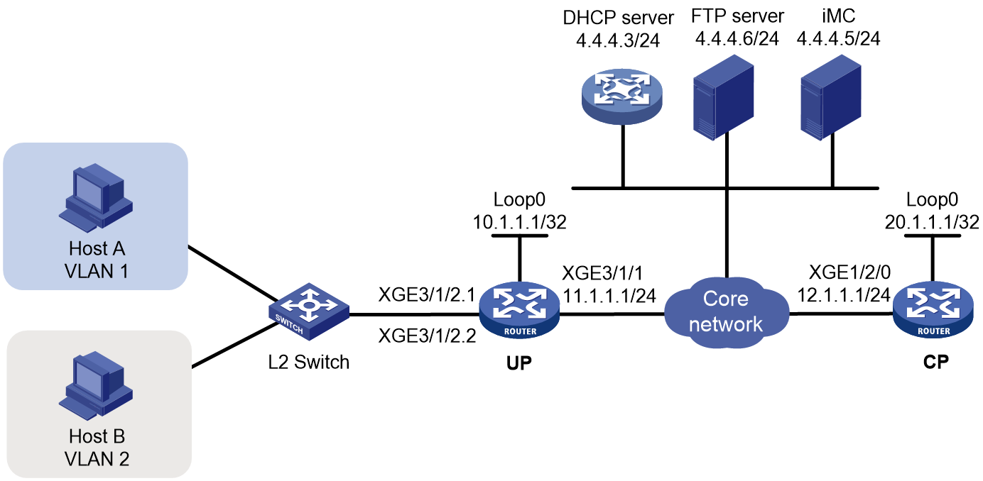
Prerequisites
Configure IP addresses for interfaces, and make sure devices can reach each other at Layer 3. (Details not shown.)
Set up the management channel, control channel, and protocol channel between the CP and UP. (Details not shown.)
Procedure
1. Configure the DHCP server:
# Enable DHCP.
<DHCP-server> system-view
[DHCP-server] dhcp enable
# Enable the DHCP server to return a DHCP-NAK message if the client notions of their IP addresses are incorrect.
[DHCP-server] dhcp server request-ip-address check
# Create an IP address pool named pool1 and enter its view.
[DHCP-server] ip pool pool1
# Specify primary subnet 192.168.1.0/24 for dynamic allocation in address pool pool1.
[DHCP-server-ip-pool-pool1] network 192.168.1.0 24
# Specify gateway address 192.168.1.1 in address pool pool1.
[DHCP-server-ip-pool-pool1] gateway-list 192.168.1.1
# Specify DNS server address 8.8.8.8 in address pool pool1.
[DHCP-server-ip-pool-pool1] dns-list 8.8.8.8
# Exclude IP address 192.168.1.1 from dynamic allocation in address pool pool1.
[DHCP-server-ip-pool-pool1] forbidden-ip 192.168.1.1
[DHCP-server-ip-pool-pool1] quit
# Create an IP address pool named pool2 and enter its view.
[DHCP-server] ip pool pool2
# Specify primary subnet 192.168.2.0/24 for dynamic allocation in address pool pool2.
[DHCP-server-ip-pool-pool2] network 192.168.2.0 24
# Specify gateway address 192.168.2.1 in address pool pool2.
[DHCP-server-ip-pool-pool2] gateway-list 192.168.2.1
# Specify DNS server address 8.8.8.8 in address pool pool2.
[DHCP-server-ip-pool-pool2] dns-list 8.8.8.8
# Exclude IP address 192.168.2.1 from dynamic allocation in address pool pool2.
[DHCP-server-ip-pool-pool2] forbidden-ip 192.168.2.1
[DHCP-server-ip-pool-pool2] quit
# Configure the default route to the CP.
[DHCP-server] ip route-static 0.0.0.0 0 12.1.1.1
2. Configure the UP:
a. Configure the UP to operate in user plane mode.
<UP> system-view
[UP] work-mode user-plane
b. Specify 11111 as the HTTPS redirect listening port number. Make sure the port number is not used by any other service. To see the TCP port numbers used by other services, execute the display tcp command.
[UP] http-redirect https-port 11111
c. Create a local user group named pre.
[UP] user-group pre
New user group added.
[UP-ugroup-pre] quit
d. Configure ACLs for preauthentication:
# Create an IPv4 advanced ACL named web_permit. Configure a rule to permit all packets destined for the portal server from users in user group pre.
[UP] acl advanced name web_permit
[UP-acl-ipv4-adv-web_permit] rule 0 permit ip destination 4.4.4.5 0 user-group pre
[UP-acl-ipv4-adv-web_permit] quit
# Create an IPv4 advanced ACL named neiwang. Configure a rule to permit all packets destined for the internal network server from users in user group pre.
[UP] acl advanced name neiwang
[UP-acl-ipv4-adv-neiwang] rule 0 permit ip destination 4.4.4.4 0 user-group pre
[UP-acl-ipv4-adv-neiwang] quit
# Create an IPv4 advanced ACL named web_http. Configure a rule to permit TCP packets with the destination port 80 (HTTP packets) from users in user group pre.
[UP] acl advanced name web_http
[UP-acl-ipv4-adv-web_http] rule 0 permit tcp destination-port eq www user-group pre
[UP-acl-ipv4-adv-web_http] quit
# Create an IPv4 advanced ACL named web_https, and configure a rule to permit TCP packets with the destination port 443 (HTTPS packets) from users in user group pre.
[UP] acl advanced name web_https
[UP-acl-ipv4-adv-web_https] rule 0 permit tcp destination-port eq 443 user-group pre
[UP-acl-ipv4-adv-web_https] quit
# Create an IPv4 advanced ACL named ip, and configure a rule to permit IP packets from users in user group pre.
[UP] acl advanced name ip
[UP-acl-ipv4-adv-ip] rule 0 permit ip user-group pre
[UP-acl-ipv4-adv-ip] quit
# Create an IPv4 advanced ACL named neiwang_out, and configure a rule to permit IP packets from the internal network server in user group pre.
[UP] acl advanced name neiwang_out
[UP-acl-ipv4-adv-neiwang_out] rule 0 permit ip source 4.4.4.4 0 user-group pre
[UP-acl-ipv4-adv-neiwang_out] quit
# Create an IPv4 advanced ACL named web_out, and configure a rule to permit IP packets from the portal server in user group pre.
[UP] acl advanced name web_out
[UP-acl-ipv4-adv-web_out] rule 0 permit ip source 4.4.4.5 0 user-group pre
[UP-acl-ipv4-adv-web_out] quit
e. Configure QoS traffic classes for preauthentication users:
# Create the traffic class web_permit and specify ACL web_permit as the match criterion.
[UP] traffic classifier web_permit operator and
[UP-classifier-web_permit] if-match acl name web_permit
[UP-classifier-web_permit] quit
# Create the traffic class neiwang and specify ACL neiwang as the match criterion.
[UP] traffic classifier neiwang operator and
[UP-classifier-neiwang] if-match acl name neiwang
[UP-classifier-neiwang] quit
# Create the traffic class web_http and specify ACL web_http as the match criterion.
[UP] traffic classifier web_http operator and
[UP-classifier-web_http] if-match acl name web_http
[UP-classifier-web_http] quit
# Create the traffic class web_https and specify ACL web_https as the match criterion.
[UP] traffic classifier web_https operator and
[UP-classifier-web_https] if-match acl name web_https
[UP-classifier-web_https] quit
# Create the traffic class web_deny and specify ACL ip as the match criterion.
[UP] traffic classifier web_deny operator and
[UP-classifier-web_deny] if-match acl name ip
[UP-classifier-web_deny] quit
# Create the traffic class neiwang_out and specify ACL neiwang_out as the match criterion.
[UP] traffic classifier neiwang_out operator and
[UP-classifier-neiwang_out] if-match acl name neiwang_out
[UP-classifier-neiwang_out] quit
# Create the traffic class web_out and specify ACL web_out as the match criterion.
[UP] traffic classifier web_out operator and
[UP-classifier-web_out] if-match acl name web_out
[UP-classifier-web_out] quit
f. Configure QoS traffic behaviors:
# Configure the traffic behavior web_permit to permit traffic to pass through without rate limiting or accounting.
[UP] traffic behavior web_permit
[UP-behavior-web_permit] filter permit
[UP-behavior-web_permit] free account
[UP-behavior-web_permit] quit
# Configure the traffic behavior neiwang to permit traffic to pass through.
[UP] traffic behavior neiwang
[UP-behavior-neiwang] filter permit
[UP-behavior-neiwang] quit
# Configure the traffic behavior web_http to redirect HTTP packets to the CPU.
[UP] traffic behavior web_http
[UP-behavior-web_http] redirect http-to-cpu
[UP-behavior-web_http] quit
# Configure the traffic behavior web_https to redirect HTTPS packets to the CPU.
[UP] traffic behavior web_https
[UP-behavior-web_https] redirect https-to-cpu
[UP-behavior-web_https] quit
# Configure the traffic behavior web_deny to deny traffic.
[UP] traffic behavior web_deny
[UP-behavior-web_deny] filter deny
[UP-behavior-web_deny] free account
[UP-behavior-web_deny] quit
# Configure the traffic behavior neiwang_out to permit traffic to pass through.
[UP] traffic behavior neiwang_out
[UP-behavior-neiwang_out] filter permit
[UP-behavior-neiwang_out] quit
# Configure the traffic behavior web_out to permit traffic without rate limiting or traffic accounting.
[UP] traffic behavior web_out
[UP-behavior-web_out] filter permit
[UP-behavior-web_out] free account
[UP-behavior-web_out] quit
g. Configure the QoS policies:
# Create a QoS policy named web.
[UP] qos policy web
# Associate the traffic class web_permit with the traffic behavior web_permit.
[UP-qospolicy-web] classifier web_permit behavior web_permit
# Associate the traffic class neiwang with the traffic behavior neiwang.
[UP-qospolicy-web] classifier neiwang behavior neiwang
# Associate the traffic class web_http with the traffic behavior web_http.
[UP-qospolicy-web] classifier web_http behavior web_http
# Associate the traffic class web_https with the traffic behavior web_https.
[UP-qospolicy-web] classifier web_https behavior web_https
# Associate the traffic class web_deny with the traffic behavior web_deny.
[UP-qospolicy-web] classifier web_deny behavior web_deny
[UP-qospolicy-web] quit
# Configure a QoS policy named out.
[UP] qos policy out
# Associate the traffic class web_out with the traffic behavior web_out. Associate the traffic class neiwang_out with the traffic behavior neiwang_out. Associate the traffic class web_deny with the traffic behavior web_deny.
[UP-qospolicy-out] classifier web_out behavior web_out
[UP-qospolicy-out] classifier neiwang_out behavior neiwang_out
[UP-qospolicy-out] classifier web_deny behavior web_deny
[UP-qospolicy-out] quit
h. Apply the QoS policies:
# Apply the QoS Policy web to the inbound traffic globally. To identify whether the QoS policy takes effect, execute the display qos policy global inbound command.
[UP] qos apply policy web global inbound
# Apply the QoS Policy out to the outbound traffic globally. To identify whether the QoS policy takes effect, execute the display qos policy global outbound command.
[UP] qos apply policy out global outbound
3. Configure the CP:
a. Configure the DHCP relay agent:
# Create a remote BAS IP address pool named pool1.
<CP> system-view
[CP] ip pool pool1 bas remote
# Specify gateway address 192.168.1.1 in address pool pool1.
[CP-ip-pool-pool1] gateway 192.168.1.1 24
# Exclude IP address 192.168.1.1 from dynamic allocation in address pool pool1.
[CP-ip-pool-pool1] forbidden-ip 192.168.1.1
# Specify DHCP server 4.4.4.3 in address pool pool1, and bind the address pool to UP 1024.
[CP-ip-pool-pool1] remote-server 4.4.4.3
[CP-ip-pool-pool1] binding up-id 1024
[CP-ip-pool-pool1] quit
# Create a remote BAS IP address pool named pool2.
[CP] ip pool pool2 bas remote
# Specify gateway address 192.168.2.1 in address pool pool2.
[CP-ip-pool-pool2] gateway-list 192.168.2.1 24
# Exclude IP address 192.168.2.1 from dynamic allocation in address pool pool2.
[CP-ip-pool-pool2] forbidden-ip 192.168.2.1
# Specify DHCP server 4.4.4.3 in address pool pool2, and bind the address pool to UP 1024.
[CP-ip-pool-pool2] remote-server 4.4.4.3
[CP-ip-pool-pool2] binding up-id 1024
[CP-ip-pool-pool2] quit
# Assign IP address 192.168.1.1 to interface Remote-XGE 1024/3/1/2.1, enable the DHCP relay agent on the interface, and specify the DHCP server address 4.4.4.3.
[CP] interface remote-xge 1024/3/1/2.1
[CP–Remote-XGE1024/3/1/2.1] ip address 192.168.1.1 24
[CP–Remote-XGE1024/3/1/2.1] dhcp select relay
[CP–Remote-XGE1024/3/1/2.1] dhcp relay server-address 4.4.4.3
[CP–Remote-XGE1024/3/1/2.1] quit
# Assign IP address 192.168.2.1 to interface Remote-XGE 1024/3/1/2.2, enable the DHCP relay agent on the interface, and specify the DHCP server address 4.4.4.3.
[CP] interface remote-xge 1024/3/1/2.2
[CP–Remote-XGE1024/3/1/2.2] ip address 192.168.2.1 24
[CP–Remote-XGE1024/3/1/2.2] dhcp select relay
[CP–Remote-XGE1024/3/1/2.2] dhcp relay server-address 4.4.4.3
[CP–Remote-XGE1024/3/1/2.2] quit
b. Configure VLAN termination:
# Enable user mode of VLAN termination on Remote-XGE 1024/3/1/2.1 and Remote-XGE 1024/3/1/2.2. This feature prevents the subinterface restart and protects the online user state.
[CP] interface range remote-xge 1024/3/1/2.1 remote-xge 1024/3/1/2.2
[CP–if-range] vlan-termination user-mode
[CP–if-range] quit
# Configure Remote-XGE 1024/3/1/2.1 to terminate VLAN-tagged packets with the outermost VLAN tag as 1.
[CP] interface remote-xge 1024/3/1/2.1
[CP–Remote-XGE1024/3/1/2.1] user-vlan dot1q vid 1
[CP–Remote-XGE1024/3/1/2.1] quit
# Configure Remote-XGE 1024/3/1/2.2 to terminate VLAN-tagged packets with the outermost VLAN tag as 2.
[CP] interface remote-xge 1024/3/1/2.2
[CP–Remote-XGE1024/3/1/2.2] user-vlan dot1q vid 2
[CP–Remote-XGE1024/3/1/2.2] quit
c. Configure the IP address of the portal authentication server newpt as 4.4.4.5 and the plaintext key 123456.
[CP] portal server newpt
[CP-portal-server-newpt] ip 4.4.4.5 key simple 123456
[CP-portal-server-newpt] quit
d. Configure the CP to get user access information from ARP and ND entries.
[CP] portal access-info trust arp
[CP] portal access-info trust nd
e. Create a local user group named pre.
[CP] user-group pre
New user group added.
[CP-ugroup-pre] quit
f. Configure a RADIUS scheme:
# Create a RADIUS scheme named rs1 and enter its view.
[CP] radius scheme rs1
# Configure primary servers and keys for authentication and accounting.
[CP-radius-rs1] primary authentication 4.4.4.5
[CP-radius-rs1] primary accounting 4.4.4.5
[CP-radius-rs1] key authentication simple radius
[CP-radius-rs1] key accounting simple radius
# Exclude the ISP name from the username sent to the RADIUS server.
[CP-radius-rs1] user-name-format without-domain
[CP-radius-rs1] quit
g. Configure the preauthentication ISP domain and Web authentication ISP domain:
# Configure the ISP domain dm1 for IPoE user preauthentication.
[CP] domain name dm1
[CP-isp-dm1] authentication ipoe none
[CP-isp-dm1] authorization ipoe none
[CP-isp-dm1] accounting ipoe none
# Configure the authorized user group in preauthentication ISP domain dm1.
[CP-isp-dm1] authorization-attribute user-group pre
# Configure the Web authentication page URL and Web server IP address in ISP domain dm1.
[CP-isp-dm1] web-server url http://4.4.4.5:8080/portal/
[CP-isp-dm1] web-server ip 4.4.4.5
[CP-isp-dm1] quit
# Configure the ISP domain dm2 for IPoE user Web authentication.
[CP] domain name dm2
[CP-isp-dm2] authentication ipoe radius-scheme rs1
[CP-isp-dm2] authorization ipoe radius-scheme rs1
[CP-isp-dm2] accounting ipoe radius-scheme rs1
[CP-isp-dm2] quit
h. Configure IPoE:
# Enable IPoE and configure Layer 2 access mode on subinterfaces Remote-XGE 1024/3/1/2.1 and Remote-XGE 1024/3/1/2.2.
[CP] interface range remote-xge 1024/3/1/2.1 remote-xge 1024/3/1/2.2
[CP–if-range] ip subscriber l2-connected enable
# Configure Web authentication for IPoE users on subinterfaces Remote-XGE 1024/3/1/2.1 and Remote-XGE 1024/3/1/2.2.
[CP–if-range] ip subscriber authentication-method web
The operation may cut all users on this interface. Continue?[Y/N]:y
# Configure the ISP domain dm1 for preauthentication and the ISP domain dm2 for Web authentication on subinterfaces Remote-XGE 1024/3/1/2.1 and Remote-XGE 1024/3/1/2.2.
[CP–if-range] ip subscriber pre-auth domain dm1
[CP–if-range] ip subscriber web-auth domain dm2
[CP–if-range] quit
4. Configure the RADIUS server and portal server.
For more information, see "Example: Configuring IPoE common Web authentication for DHCPv4 users (assigning a remote BAS IP address pool)."
Verifying the configuration
# Display IPoE session information to verify that hosts A and B have passed preauthentication.
[CP] display access-user auth-type pre-auth
Slot 97:
UserID Interface IP address MAC address S-/C-VLAN
Username IPv6 address Access type
0x1 R-XGE1024/3/1/2.1 192.168.1.2 0015-e947-f4d4 1/-
0015e947f4d4 - L2 IPoE dynamic
0x2 R-XGE1024/3/1/2.2 192.168.2.2 0015-e947-f4d5 2/-
0015e947f4d5 - L2 IPoE dynamic
As shown in Figure 212, the Web login page opens after preauthentication. Enter the username and password on the page.
# Display IPoE session information to verify that the host has passed Web authentication and come online.
[CP] display access-user auth-type web-auth
Slot 97:
UserID Interface IP address MAC address S-/C-VLAN
Username IPv6 address Access type
0x1 R-XGE1024/3/1/2.1 192.168.1.2 0015-e947-f4d4 1/-
user1@dm2 - Web auth
0x2 R-XGE1024/3/1/2.2 192.168.2.2 0015-e947-f4d5 2/-
user1@dm2 - Web auth
Example: Configuring IPoE common Web authentication for DHCPv6 users (assigning a remote BAS IPv6 address pool)
Network configuration
As shown in Figure 213:
· The host accesses the BRAS as a DHCP client though a Layer 2 device.
· The host obtains configuration information from the DHCP server through the BRAS.
· The BRAS performs AAA for the host through the RADIUS server. A server installed with H3C IMC acts as the RADIUS server, the portal authentication server, and the portal Web server.
· The FTP server is an internal network server.
· Limit the access rate to 5 Mbps for the user after passing Web authentication.
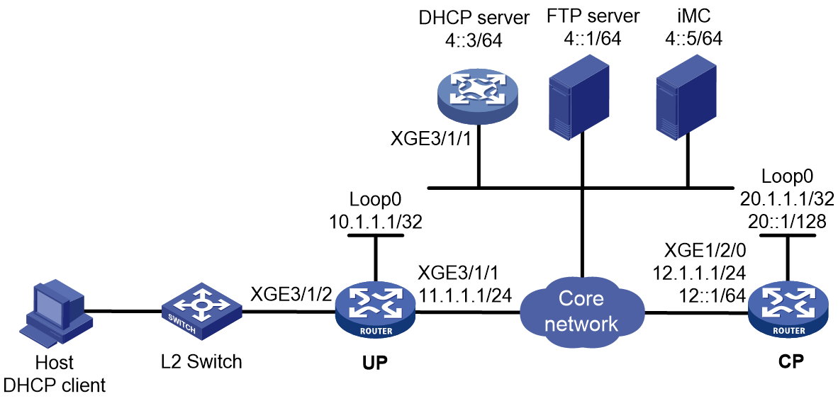
Prerequisites
Configure the DNS server properly, so that the server can parse the IPv6 URL corresponding to the Web authentication page http://www.ipv6.web.com. (Details not shown.)
Configure IP addresses for interfaces and make sure the BRAS and servers can reach each other at Layer 3. (Details not shown.)
Set up the management channel, control channel, and protocol channel between the CP and UP. (Details not shown.)
Procedure
1. Configure the DHCP server:
# Create a DHCPv6 address pool named pool1 and enter its view.
<DHCP-server> system-view
[DHCP-server] ipv6 pool pool1
# Specify primary subnet 192::/64 and DNS server address 8::8 for dynamic allocation in DHCPv6 address pool pool1.
[DHCP-server-ipv6-pool-pool1] network 192::/64
[DHCP-server-ipv6-pool-pool1] dns-server 8::8
[DHCP-server-ipv6-pool-pool1] quit
# Exclude IP address 192::1 from dynamic allocation in DHCPv6 address pool pool1.
[DHCP-server] ipv6 dhcp server forbidden-address 192::1
# Enable the DHCPv6 server on Ten-GigabitEthernet 3/1/1.
[DHCP-server] interface ten-gigabitethernet 3/1/1
[DHCP-server-Ten-GigabitEthernet3/1/1] ipv6 dhcp select server
[DHCP-server-Ten-GigabitEthernet3/1/1] quit
# Configure the default route to the CP.
[DHCP-server] ipv6 route-static :: 0 12::1
2. Configure the UP:
a. Configure the UP to operate in user plane mode.
<UP> system-view
[UP] work-mode user-plane
b. Specify 11111 as the HTTPS redirect listening port number. Make sure the port number is not used by any other service. To see the TCP port numbers used by other services, execute the display tcp command.
[UP] http-redirect https-port 11111
c. Create a local user group named pre.
[UP] user-group pre
New user group added.
[UP-ugroup-pre] quit
d. Configure ACLs for preauthentication:
# Create an IPv6 advanced ACL named web_permit. Configure a rule to permit all packets destined for the portal server from users in user group pre.
[UP] acl ipv6 advanced name web_permit
[UP-acl-ipv6-adv-web_permit] rule 0 permit ipv6 destination 4::5 128 user-group pre
[UP-acl-ipv6-adv-web_permit] quit
# Create an IPv6 advanced ACL named neiwang. Configure a rule to permit all packets destined for the internal network server from users in user group pre.
[UP] acl ipv6 advanced name neiwang
[UP-acl-ipv6-adv-neiwang] rule 0 permit ipv6 destination 4::1 128 user-group pre
[UP-acl-ipv6-adv-neiwang] quit
# Create an IPv6 advanced ACL named web_http. Configure a rule to permit TCP packets with the destination port 80 (HTTP packets) from users in user group pre.
[UP] acl ipv6 advanced name web_http
[UP-acl-ipv6-adv-web_http] rule 0 permit tcp destination-port eq www user-group pre
[UP-acl-ipv6-adv-web_http] quit
# Create an IPv6 advanced ACL named web_https, and configure a rule to permit TCP packets with the destination port 443 (HTTPS packets) from users in user group pre.
[UP] acl ipv6 advanced name web_https
[UP-acl-ipv6-adv-web_https] rule 0 permit tcp destination-port eq 443 user-group pre
[UP-acl-ipv6-adv-web_https] quit
# Create an IPv6 advanced ACL named ip, and configure a rule to permit IP packets from users in user group pre.
[UP] acl ipv6 advanced name ip
[UP-acl-ipv6-adv-ip] rule 0 permit ipv6 user-group pre
[UP-acl-ipv6-adv-ip] quit
# Create an IPv6 advanced ACL named neiwang_out, and configure a rule to permit IP packets from the internal network server in user group pre.
[UP] acl ipv6 advanced name neiwang_out
[UP-acl-ipv6-adv-neiwang_out] rule 0 permit ipv6 source 4::1 128 user-group pre
[UP-acl-ipv6-adv-neiwang_out] quit
# Create an IPv6 advanced ACL named web_out, and configure a rule to permit IP packets from the portal server in user group pre.
[UP] acl ipv6 advanced name web_out
[UP-acl-ipv6-adv-web_out] rule 0 permit ipv6 source 4::5 128 user-group pre
[UP-acl-ipv6-adv-web_out] quit
e. Configure QoS traffic classes for preauthentication users:
# Create the traffic class web_permit and specify ACL web_permit as the match criterion.
[UP] traffic classifier web_permit operator or
[UP-classifier-web_permit] if-match acl ipv6 name web_permit
[UP-classifier-web_permit] quit
# Create the traffic class neiwang and specify ACL neiwang as the match criterion.
[UP] traffic classifier neiwang operator or
[UP-classifier-neiwang] if-match ipv6 acl name neiwang
[UP-classifier-neiwang] quit
# Create the traffic class web_http and specify ACL web_http as the match criterion.
[UP] traffic classifier web_http operator or
[UP-classifier-web_http] if-match ipv6 acl name web_http
[UP-classifier-web_http] quit
# Create the traffic class web_https and specify ACL web_https as the match criterion.
[UP] traffic classifier web_https operator or
[UP-classifier-web_https] if-match ipv6 acl name web_https
[UP-classifier-web_https] quit
# Create the traffic class web_deny and specify ACL ip as the match criterion.
[UP] traffic classifier web_deny operator or
[UP-classifier-web_deny] if-match ipv6 acl name ip
[UP-classifier-web_deny] quit
# Create the traffic class neiwang_out and specify ACL neiwang_out as the match criterion.
[UP] traffic classifier neiwang_out operator or
[UP-classifier-neiwang_out] if-match ipv6 acl name neiwang_out
[UP-classifier-neiwang_out] quit
# Create the traffic class web_out and specify ACL web_out as the match criterion.
[UP] traffic classifier web_out operator or
[UP-classifier-web_out] if-match ipv6 acl name web_out
[UP-classifier-web_out] quit
f. Configure QoS traffic behaviors:
# Configure the traffic behavior web_permit to permit traffic to pass through without rate limiting or accounting.
[UP] traffic behavior web_permit
[UP-behavior-web_permit] filter permit
[UP-behavior-web_permit] free account
[UP-behavior-web_permit] quit
# Configure the traffic behavior neiwang to permit traffic to pass through.
[UP] traffic behavior neiwang
[UP-behavior-neiwang] filter permit
[UP-behavior-neiwang] quit
# Configure the traffic behavior web_http to redirect HTTP packets to the CPU.
[UP] traffic behavior web_http
[UP-behavior-web_http] redirect http-to-cpu
[UP-behavior-web_http] quit
# Configure the traffic behavior web_https to redirect HTTPS packets to the CPU.
[UP] traffic behavior web_https
[UP-behavior-web_https] redirect https-to-cpu
[UP-behavior-web_https] quit
# Configure the traffic behavior web_deny to deny traffic.
[UP] traffic behavior web_deny
[UP-behavior-web_deny] filter deny
[UP-behavior-web_deny] free account
[UP-behavior-web_deny] quit
# Configure the traffic behavior neiwang_out to permit traffic to pass through.
[UP] traffic behavior neiwang_out
[UP-behavior-neiwang_out] filter permit
[UP-behavior-neiwang_out] quit
# Configure the traffic behavior web_out to permit traffic without rate limiting or traffic accounting.
[UP] traffic behavior web_out
[UP-behavior-web_out] filter permit
[UP-behavior-web_out] free account
[UP-behavior-web_out] quit
g. Configure the QoS policies:
# Create a QoS policy named web.
[UP] qos policy web
# Associate the traffic class web_permit with the traffic behavior web_permit.
[UP-qospolicy-web] classifier web_permit behavior web_permit
# Associate the traffic class neiwang with the traffic behavior neiwang.
[UP-qospolicy-web] classifier neiwang behavior neiwang
# Associate the traffic class web_http with the traffic behavior web_http.
[UP-qospolicy-web] classifier web_http behavior web_http
# Associate the traffic class web_https with the traffic behavior web_https.
[UP-qospolicy-web] classifier web_https behavior web_https
# Associate the traffic class web_deny with the traffic behavior web_deny.
[UP-qospolicy-web] classifier web_deny behavior web_deny
[UP-qospolicy-web] quit
# Configure a QoS policy named out.
[UP] qos policy out
# Associate the traffic class web_out with the traffic behavior web_out. Associate the traffic class neiwang_out with the traffic behavior neiwang_out. Associate the traffic class web_deny with the traffic behavior web_deny.
[UP-qospolicy-out] classifier web_out behavior web_out
[UP-qospolicy-out] classifier neiwang_out behavior neiwang_out
[UP-qospolicy-out] classifier web_deny behavior web_deny
[UP-qospolicy-out] quit
h. Apply the QoS policies:
# Apply the QoS Policy web to the inbound traffic globally. To identify whether the QoS policy takes effect, execute the display qos policy global inbound command.
[UP] qos apply policy web global inbound
# Apply the QoS Policy out to the outbound traffic globally. To identify whether the QoS policy takes effect, execute the display qos policy global outbound command.
[UP] qos apply policy out global outbound
3. Configure the CP:
a. Configure the DHCP relay agent:
# Create a remote BAS IP address pool named pool1 for the DHCP relay agent.
<CP> system-view
[CP] ipv6 pool pool1 bas remote
[CP-ipv6-pool-pool1] gateway-list 192::1
[CP-ipv6-pool-pool1] network 192::/64 export-route
[CP-ipv6-pool-pool1] remote-server 4::3
[CP-ipv6-pool-pool1] dhcpv6-relay source-address interface loopback 0
[CP-ipv6-pool-pool1] binding up-id 1024
[CP-ipv6-pool-pool1] quit
# Automatically generate a link-local address for Remote-XGE 1024/3/1/2.
[CP] interface remote-xge 1024/3/1/2
[CP–Remote-XGE1024/3/1/2] ipv6 address auto link-local
# Enable the DHCPv6 relay agent on Remote-XGE 1024/3/1/2.
[CP–Remote-XGE1024/3/1/2] ipv6 dhcp select relay
# Enable recording client information in DHCPv6 relay entries.
[CP–Remote-XGE1024/3/1/2] ipv6 dhcp relay client-information record
# Disable RA message suppression on Remote-XGE 1024/3/1/2.
[CP–Remote-XGE1024/3/1/2] undo ipv6 nd ra halt
# Set the managed address configuration flag (M) to 1 in RA advertisements to be sent. Then, the host uses a DHCPv6 server to obtain IPv6 addresses.
[CP–Remote-XGE1024/3/1/2] ipv6 nd autoconfig managed-address-flag
# Set the other stateful configuration flag (O) to 1 in RA advertisements to be sent. Then, the host uses a DHCPv6 server to obtain configuration information other than IPv6 addresses.
[CP–Remote-XGE1024/3/1/2] ipv6 nd autoconfig other-flag
# Disable Remote-XGE 1024/3/1/2 from advertising the specified prefix in RA messages, preventing the endpoint from obtaining a temporary IPv6 address. In an IPv6 network, an endpoint might use a temporary IPv6 address for IPoE Web authentication, which will cause authentication failure.
[CP–Remote-XGE1024/3/1/2] ipv6 nd ra prefix 192::/64 no-advertise
[CP–Remote-XGE1024/3/1/2] quit
b. Configure the IPv6 address of the IPv6 portal authentication server newpt1 as 4::5 and the plaintext key 123456.
[CP] portal server newpt1
[CP-portal-server-newpt1] ipv6 4::5 key simple 123456
[CP-portal-server-newpt1] quit
c. Configure the CP to get user access information from ARP and ND entries.
[CP] portal access-info trust arp
[CP] portal access-info trust nd
d. Create a local user group named pre.
[CP] user-group pre
New user group added.
[CP-ugroup-pre] quit
e. Configure a RADIUS scheme:
# Create a RADIUS scheme named rs1 and enter its view.
[CP] radius scheme rs1
# Configure primary servers and keys for authentication and accounting.
[CP-radius-rs1] primary authentication ipv6 4::5
[CP-radius-rs1] primary accounting ipv6 4::5
[CP-radius-rs1] key authentication simple radius
[CP-radius-rs1] key accounting simple radius
# Exclude the ISP name from the username sent to the RADIUS server.
[CP-radius-rs1] user-name-format without-domain
[CP-radius-rs1] quit
# Set the IP address of the RADIUS DAE client to 4::5, and set the shared key to radius for the RADIUS DAE client to exchange DAE packets.
[CP] radius dynamic-author server
[CP-radius-da-server] client ipv6 4::5 key simple radius
[CP-radius-da-server] quit
f. Configure the preauthentication ISP domain and Web authentication ISP domain:
# Configure the ISP domain dm1 for IPoE user preauthentication.
[CP] domain name dm1
[CP-isp-dm1] authentication ipoe none
[CP-isp-dm1] authorization ipoe none
[CP-isp-dm1] accounting ipoe none
# Configure the authorized user group and IPv6 address pool in preauthentication ISP domain dm1.
[CP-isp-dm1] authorization-attribute user-group pre
[CP-isp-dm1] authorization-attribute ipv6-pool pool1
# Configure the Web authentication page URL in ISP domain dm1.
[CP-isp-dm1] web-server ipv6-url http://www.ipv6.web.com
[CP-isp-dm1] quit
# Configure the ISP domain dm2 for IPoE user Web authentication.
[CP] domain name dm2
[CP-isp-dm2] authentication ipoe radius-scheme rs1
[CP-isp-dm2] authorization ipoe radius-scheme rs1
[CP-isp-dm2] accounting ipoe radius-scheme rs1
[CP-isp-dm2] authorization-attribute car inbound cir 5120 outbound cir 5120
[CP-isp-dm2] quit
g. Configure IPoE:
# Enable IPoE for the IPv6 protocol stack and configure Layer 2 access mode on Remote-XGE 1024/3/1/2.
[CP] interface remote-xge 1024/3/1/2
[CP–Remote-XGE1024/3/1/2] ip subscriber l2-connected enable ipv6
# Configure Web authentication for IPoE users on Remote-XGE 1024/3/1/2.
[CP–Remote-XGE1024/3/1/2] ip subscriber authentication-method web
The operation may cut all users on this interface. Continue?[Y/N]:y
# Configure the ISP domain dm1 for preauthentication and the ISP domain dm2 for Web authentication on Remote-XGE 1024/3/1/2.
[CP–Remote-XGE1024/3/1/2] ip subscriber pre-auth domain dm1
[CP–Remote-XGE1024/3/1/2] ip subscriber web-auth domain dm2
[CP–Remote-XGE1024/3/1/2] quit
4. Configure the RADIUS server:
a. Configure the access device:
- Log in to the IMC platform and click the User tab.
- Select User Access Policy > Access Device Management > Access Device from the navigation tree to open the access device configuration page.
- Click Add to open the page as shown in Figure 214.
- Enter the shared key radius.
- Use the default settings for other parameters.
Figure 214 Adding an access device

- Click Add IPv6 Dev in the Device List area.
- Enter the access device's IPv6 address 12::1.
- Click OK.
a. Add an access policy:
- Select User Access Policy > Access Policy from the navigation tree to open the access policy page.
- Click Add to open the page as shown in Figure 215.
- Enter the access policy name AccessPolicy.
- Use the default settings for other parameters.
Figure 215 Adding an access policy

a. Add an access service:
- Select User Access Policy > Access Service from the navigation tree to open the access service page.
- Click Add to open the page as shown in Figure 216.
- Enter the service name IPoE_Server.
- Select AccessPolicy from the default access policy list.
- Use the default settings for other parameters.
Figure 216 Adding an access service

a. Add a user:
- Select User Management > Add User from the navigation tree to open the adding user page, as shown in Figure 217.
- Enter the username IPoE_Web001 and the user ID 001.
- Click OK.

a. Add an access user:
- Select Access User > All Access Users from the navigation tree to open the access user page.
- Click Add to open the page as shown in Figure 218.
- Select IPoE_Web001 for the username.
- Enter the account name user1.
- Enter the password pass1.
- Select the access service IPoE_Server.
Figure 218 Adding an access user

5. Configure the portal server:
a. Configure the portal homepage:
- Select User Access Policy > Portal Service > Server from the navigation tree to open the portal server configuration page, as shown in Figure 219.
- Click OK.
Figure 219 Portal server configuration page

a. Configure portal authentication source IP address range:
- Select User Access Policy > Portal Service > IP Group from the navigation tree to open the portal IP address group configuration page.
- Click Add to open the page as shown in Figure 220.
- Enter the IP group name IPoE_Web_User-2.
- Select Yes from the IPv6 list.
- Enter the start IP address (192::1) and end IP address (192::FFFF) of the IP group. Make sure the host IPv6 address is in the IP group.
- Click OK.
Figure 220 Adding an IP address group (IPv6)
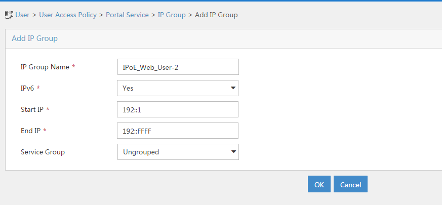
a. Add a portal device:
- Select User Access Policy > Portal Service > Device from the navigation tree to open the portal device configuration page.
- Click Add.
- Enter the device name NAS-2.
- Select Portal 3.0 from the Version list.
- Enter the IP address of the portal packets' outgoing interface Ten-GigabitEthernet 3/1/2 (12::1).
- Enter the key 123456.
- Select Directly Connect for access method.
- Click OK.
b. Associate the portal device with the IP address group:
- Click the icon in the Port Group Information Management column of device NAS to open the port group configuration page, as shown in Figure 221.
- Click Add to open the page as shown in Figure 222.
- Enter the port group name group-2.
- Select the configured IP address group IPoE_Web_User-2. Make sure the IPv6 address used by the user to access the network is within this IPv6 address group.
- Click OK.

Figure 222 Port group configuration

Verifying the configuration
# Display IPoE session information to verify that the host has passed preauthentication and obtained IPv6 address 192::2.
[CP] display access-user auth-type pre-auth interface remote-xge 1024/3/1/2
Slot 97:
UserID Interface IP address MAC address S-/C-VLAN
Username IPv6 address Access type
0x33d R-XGE1024/3/1/2 - 001b-21a8-0949 -/-
001b21a80949 192::2 L2 IPoE dynamic
As shown in Figure 223, the Web login page opens after preauthentication. Enter the username and password on the page.
# Display IPoE session information to verify that the host has passed Web authentication and come online.
[CP] display access-user auth-type web-auth interface remote-xge 1024/3/1/2
Slot 97:
UserID Interface IP address MAC address S-/C-VLAN
Username IPv6 address Access type
0x33d R-XGE1024/3/1/2 - 001b-21a8-0949 -/-
user1@dm2 192::2 Web auth
Example: Configuring IPoE common Web authentication for IPoE ND RS users (ND prefix pool-authorized prefix)
Network configuration
As shown in Figure 224, the host accesses the BRAS as an IPv6 ND RS user though a Layer 2 device. The BRAS can send IPv6 ND RA packets. A server installed with H3C IMC acts as the RADIUS server, the portal authentication server, and the portal Web server.
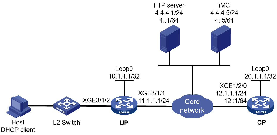
Prerequisites
Configure IP addresses for interfaces, and make sure devices can reach each other at Layer 3. (Details not shown.)
Set up the management channel, control channel, and protocol channel between the CP and UP. (Details not shown.)
Procedure
1. Configure the UP:
a. Configure the UP to operate in user plane mode.
<UP> system-view
[UP] work-mode user-plane
b. Specify 11111 as the HTTPS redirect listening port number. Make sure the port number is not used by any other service. To see the TCP port numbers used by other services, execute the display tcp command.
[UP] http-redirect https-port 11111
c. Create a local user group named pre.
[UP] user-group pre
New user group added.
[UP-ugroup-pre] quit
d. Configure ACLs for preauthentication:
# Create an IPv6 advanced ACL named web_permit. Configure a rule to permit all packets destined for the portal server from users in user group pre.
[UP] acl ipv6 advanced name web_permit
[UP-acl-ipv6-adv-web_permit] rule 0 permit ipv6 destination 4::5 128 user-group pre
[UP-acl-ipv6-adv-web_permit] quit
# Create an IPv6 advanced ACL named neiwang. Configure a rule to permit all packets destined for the internal network server from users in user group pre.
[UP] acl ipv6 advanced name neiwang
[UP-acl-ipv6-adv-neiwang] rule 0 permit ipv6 destination 4::1 128 user-group pre
[UP-acl-ipv6-adv-neiwang] quit
# Create an IPv6 advanced ACL named web_http. Configure a rule to permit TCP packets with the destination port 80 (HTTP packets) from users in user group pre.
[UP] acl ipv6 advanced name web_http
[UP-acl-ipv6-adv-web_http] rule 0 permit tcp destination-port eq www user-group pre
[UP-acl-ipv6-adv-web_http] quit
# Create an IPv6 advanced ACL named web_https, and configure a rule to permit TCP packets with the destination port 443 (HTTPS packets) from users in user group pre.
[UP] acl ipv6 advanced name web_https
[UP-acl-ipv6-adv-web_https] rule 0 permit tcp destination-port eq 443 user-group pre
[UP-acl-ipv6-adv-web_https] quit
# Create an IPv6 advanced ACL named ip, and configure a rule to permit IP packets from users in user group pre.
[UP] acl ipv6 advanced name ip
[UP-acl-ipv6-adv-ip] rule 0 permit ipv6 user-group pre
[UP-acl-ipv6-adv-ip] quit
# Create an IPv6 advanced ACL named neiwang_out, and configure a rule to permit IP packets from the internal network server in user group pre.
[UP] acl ipv6 advanced name neiwang_out
[UP-acl-ipv6-adv-neiwang_out] rule 0 permit ipv6 source 4::1 128 user-group pre
[UP-acl-ipv6-adv-neiwang_out] quit
# Create an IPv6 advanced ACL named web_out, and configure a rule to permit IP packets from the portal server in user group pre.
[UP] acl ipv6 advanced name web_out
[UP-acl-ipv6-adv-web_out] rule 0 permit ipv6 source 4::5 128 user-group pre
[UP-acl-ipv6-adv-web_out] quit
e. Configure QoS traffic classes for preauthentication users:
# Create the traffic class web_permit and specify ACL web_permit as the match criterion.
[UP] traffic classifier web_permit operator or
[UP-classifier-web_permit] if-match acl ipv6 name web_permit
[UP-classifier-web_permit] quit
# Create the traffic class web_http and specify ACL web_http as the match criterion.
[UP] traffic classifier web_http operator or
[UP-classifier-web_http] if-match acl ipv6 name web_http
[UP-classifier-web_http] quit
# Create the traffic class web_https and specify ACL web_https as the match criterion.
[UP] traffic classifier web_https operator or
[UP-classifier-web_https] if-match acl ipv6 name web_https
[UP-classifier-web_https] quit
# Create the traffic class web_deny and specify ACL ip as the match criterion.
[UP] traffic classifier web_deny operator or
[UP-classifier-web_deny] if-match acl ipv6 name ip
[UP-classifier-web_deny] quit
# Create the traffic class neiwang_out and specify ACL neiwang_out as the match criterion.
[UP] traffic classifier neiwang_out operator or
[UP-classifier-neiwang_out] if-match acl ipv6 name neiwang_out
[UP-classifier-neiwang_out] quit
# Create the traffic class web_out and specify ACL web_out as the match criterion.
[UP] traffic classifier web_out operator or
[UP-classifier-web_out] if-match acl ipv6 name web_out
[UP-classifier-web_out] quit
f. Configure QoS traffic behaviors:
# Configure the traffic behavior web_permit to permit traffic to pass through without rate limiting or accounting.
[UP] traffic behavior web_permit
[UP-behavior-web_permit] filter permit
[UP-behavior-web_permit] free account
[UP-behavior-web_permit] quit
# Configure the traffic behavior neiwang to permit traffic to pass through.
[UP] traffic behavior neiwang
[UP-behavior-neiwang] filter permit
[UP-behavior-neiwang] quit
# Configure the traffic behavior web_http to redirect HTTP packets to the CPU.
[UP] traffic behavior web_http
[UP-behavior-web_http] redirect http-to-cpu
[UP-behavior-web_http] quit
# Configure the traffic behavior web_https to redirect HTTPS packets to the CPU.
[UP] traffic behavior web_https
[UP-behavior-web_https] redirect https-to-cpu
[UP-behavior-web_https] quit
# Configure the traffic behavior web_deny to deny traffic.
[UP] traffic behavior web_deny
[UP-behavior-web_deny] filter deny
[UP-behavior-web_deny] free account
[UP-behavior-web_deny] quit
# Configure the traffic behavior neiwang_out to permit traffic to pass through.
[UP] traffic behavior neiwang_out
[UP-behavior-neiwang_out] filter permit
[UP-behavior-neiwang_out] quit
# Configure the traffic behavior web_out to permit traffic without rate limiting or traffic accounting.
[UP] traffic behavior web_out
[UP-behavior-web_out] filter permit
[UP-behavior-web_out] free account
[UP-behavior-web_out] quit
g. Configure the QoS policies:
# Create a QoS policy named web.
[UP] qos policy web
# Associate the traffic class web_permit with the traffic behavior web_permit.
[UP-qospolicy-web] classifier web_permit behavior web_permit
# Associate the traffic class neiwang with the traffic behavior neiwang.
[UP-qospolicy-web] classifier neiwang behavior neiwang
# Associate the traffic class web_http with the traffic behavior web_http.
[UP-qospolicy-web] classifier web_http behavior web_http
# Associate the traffic class web_https with the traffic behavior web_https.
[UP-qospolicy-web] classifier web_https behavior web_https
# Associate the traffic class web_deny with the traffic behavior web_deny.
[UP-qospolicy-web] classifier web_deny behavior web_deny
[UP-qospolicy-web] quit
# Configure a QoS policy named out.
[UP] qos policy out
# Associate the traffic class web_out with the traffic behavior web_out. Associate the traffic class neiwang_out with the traffic behavior neiwang_out. Associate the traffic class web_deny with the traffic behavior web_deny.
[UP-qospolicy-out] classifier web_out behavior web_out
[UP-qospolicy-out] classifier neiwang_out behavior neiwang_out
[UP-qospolicy-out] classifier web_deny behavior web_deny
[UP-qospolicy-out] quit
h. Apply the QoS policies:
# Apply the QoS Policy web to the inbound traffic globally. To identify whether the QoS policy takes effect, execute the display qos policy global inbound command.
[UP] qos apply policy web global inbound
# Apply the QoS Policy out to the outbound traffic globally. To identify whether the QoS policy takes effect, execute the display qos policy global outbound command.
[UP] qos apply policy out global outbound
2. Configure the CP:
a. Disable RA message suppression on Remote-XGE 1024/3/1/2.
<CP> system-view
[CP] interface remote-xge 1024/3/1/2
[CP–Remote-XGE1024/3/1/2] undo ipv6 nd ra halt
b. Automatically generate a link-local address for Remote-XGE 1024/3/1/2.
[CP–Remote-XGE1024/3/1/2] ipv6 address auto link-local
[CP–Remote-XGE1024/3/1/2] quit
c. Configure the ND prefix pool:
# Create prefix pool 1 that contains the prefix 10::/16 and specify the length of prefixes to be assigned as 32. Prefix pool 1 can assign 65536 prefixes in the range of 10::/32 to 10:FFFF::/32.
[CP] ipv6 dhcp prefix-pool 1 prefix 10::/16 assign-len 32
# Create an ODAP IPv6 address pool named pool1, and apply prefix pool 1. Specify IPv6 prefix length 64 for IPv6 prefix range assignment in the IPv6 address pool.
[CP] ipv6 pool pool1 odap
[CP-ipv6-pool-pool1] prefix-pool 1
[CP-ipv6-pool-pool1] dynamic prefix assign-length 64
[CP-ipv6-pool-pool1] quit
d. Configure the IPv6 address of the IPv6 portal authentication server newpt2 as 4::5 and the plaintext key 123456.
[CP] portal server newpt2
[CP-portal-server-newpt2] ipv6 4::5 key simple 123456
[CP-portal-server-newpt2] quit
e. Configure the CP to get user access information from ARP and ND entries.
[CP] portal access-info trust arp
[CP] portal access-info trust nd
f. Create a local user group named pre.
[CP] user-group pre
New user group added.
[CP-ugroup-pre] quit
g. Configure a RADIUS scheme:
# Create a RADIUS scheme named rs1 and enter its view.
[CP] radius scheme rs1
# Configure primary servers and keys for authentication and accounting.
[CP-radius-rs1] primary authentication ipv6 4::5
[CP-radius-rs1] primary accounting ipv6 4::5
[CP-radius-rs1] key authentication simple radius
[CP-radius-rs1] key accounting simple radius
# Exclude the ISP name from the username sent to the RADIUS server.
[CP-radius-rs1] user-name-format without-domain
[CP-radius-rs1] quit
h. Configure the preauthentication ISP domain and Web authentication ISP domain:
# Configure the ISP domain dm1 for IPoE user preauthentication.
[CP] domain name dm1
[CP-isp-dm1] authentication ipoe none
[CP-isp-dm1] authorization ipoe none
[CP-isp-dm1] accounting ipoe none
# Configure the authorized user group, ND prefix pool, and IPv6 DNS address pool in preauthentication ISP domain dm1.
[CP-isp-dm1] authorization-attribute user-group pre
[CP-isp-dm1] authorization-attribute ipv6-nd-prefix-pool pool1
[CP-isp-dm1] authorization-attribute primary-dns ipv6 8::8
# Configure the Web authentication page URL in ISP domain dm1.
[CP-isp-dm1] web-server ipv6-url http://[4::5]:8080/portal
[CP-isp-dm1] quit
# Configure the ISP domain dm2 for IPoE user Web authentication.
[CP] domain name dm2
[CP-isp-dm2] authentication ipoe radius-scheme rs1
[CP-isp-dm2] authorization ipoe radius-scheme rs1
[CP-isp-dm2] accounting ipoe radius-scheme rs1
[CP-isp-dm2] quit
i. Configure IPoE:
# Enable IPoE and configure Layer 2 access mode on Remote-XGE 1024/3/1/2.
[CP] interface remote-xge 1024/3/1/2
[CP–Remote-XGE1024/3/1/2] ip subscriber l2-connected enable
# Configure Web authentication for IPoE users on Remote-XGE 1024/3/1/2.
[CP–Remote-XGE1024/3/1/2] ip subscriber authentication-method web
The operation may cut all users on this interface. Continue?[Y/N]:y
# Enable IPv6 ND RS packet initiation.
[CP–Remote-XGE1024/3/1/2] ip subscriber initiator ndrs enable
# Configure the ISP domain dm1 for preauthentication and the ISP domain dm2 for Web authentication on Remote-XGE 1024/3/1/2.
[CP–Remote-XGE1024/3/1/2] ip subscriber pre-auth domain dm1
[CP–Remote-XGE1024/3/1/2] ip subscriber web-auth domain dm2
[CP–Remote-XGE1024/3/1/2] quit
3. Configure the RADIUS server and portal server.
For more information, see related configuration in "Example: Configuring IPoE common Web authentication for dual-stack users (URL allowlist)."
Verifying the configuration
# Display IPoE session information to verify that the host has passed preauthentication and obtained IPv6 prefix 10::/64.
[CP] display access-user auth-type pre-auth interface remote-xge 1024/3/1/2
Slot 97:
UserID Interface IP address MAC address S-/C-VLAN
Username IPv6 address Access type
0xc R-XGE1024/3/1/2 - 000c-29a6-b656 -/-
000c29a6b656 10::20C:29FF:FEA6:B6 L2 IPoE dynamic
56
As shown in Figure 225, the Web login page opens after preauthentication. Enter the username and password on the page.
# Display IPoE session information to verify that the host has passed Web authentication and come online.
[CP] display access-user auth-type web-auth interface remote-xge 1024/3/1/2
Slot 97:
UserID Interface IP address MAC address S-/C-VLAN
Username IPv6 address Access type
0xc R-XGE1024/3/1/2 - 000c-29a6-b656 -/-
user1@dm2 10::20C:29FF:FEA6:B6 Web auth
56
Example: Configuring IPoE transparent MAC-trigger authentication (Layer 2 transparent)
Network configuration
As shown in Figure 226, the host accesses the BRAS as a DHCP client though a Layer 2 device. It obtains configuration information from the DHCP server through the BRAS. A server installed with H3C IMC acts as the RADIUS server, the portal authentication server, the portal Web server, and the MAC binding server. This example uses IMC PLAT 7.1(E0303), IMC UAM 7.1(E0305), and IMC EIP 7.1(E0305). The FTP server is an internal network server.
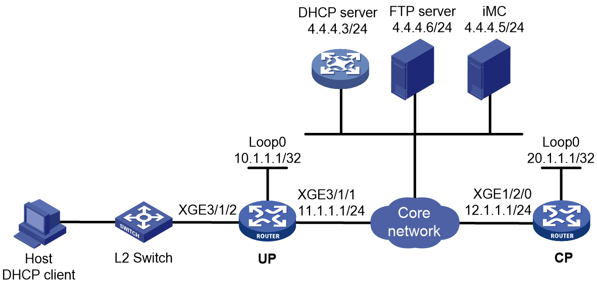
Prerequisites
Configure IP addresses for interfaces, and make sure devices can reach each other at Layer 3. (Details not shown.)
Set up the management channel, control channel, and protocol channel between the CP and UP. (Details not shown.)
Procedure
1. Configure the DHCP server:
# Enable DHCP.
<DHCP-server> system-view
[DHCP-server] dhcp enable
# Enable the DHCP server to return a DHCP-NAK message if the client notions of their IP addresses are incorrect.
[DHCP-server] dhcp server request-ip-address check
# Create an IP address pool named pool1 and enter its view.
[DHCP-server] ip pool pool1
# Specify primary subnet 192.168.0.0/24 for dynamic allocation in address pool pool1.
[DHCP-server-ip-pool-pool1] network 192.168.0.0 24
# Specify gateway address 192.168.0.1 in address pool pool1.
[DHCP-server-ip-pool-pool1] gateway-list 192.168.0.1
# Specify DNS server address 8.8.8.8 in address pool pool1.
[DHCP-server-ip-pool-pool1] dns-list 8.8.8.8
# Exclude IP address 192.168.0.1 from dynamic allocation in address pool pool1.
[DHCP-server-ip-pool-pool1] forbidden-ip 192.168.0.1
[DHCP-server-ip-pool-pool1] quit
# Configure the default route to the CP.
[DHCP-server] ip route-static 0.0.0.0 0 12.1.1.1
2. Configure the UP:
a. Configure the UP to operate in user plane mode.
<UP> system-view
[UP] work-mode user-plane
b. Specify 11111 as the HTTPS redirect listening port number. Make sure the port number is not used by any other service. To see the TCP port numbers used by other services, execute the display tcp command.
[UP] http-redirect https-port 11111
c. Create a local user group named pre.
[UP] user-group pre
New user group added.
[UP-ugroup-pre] quit
d. Configure ACLs for preauthentication:
# Create an IPv4 advanced ACL named web_permit. Configure a rule to permit all packets destined for the portal server from users in user group pre.
[UP] acl advanced name web_permit
[UP-acl-ipv4-adv-web_permit] rule 0 permit ip destination 4.4.4.5 0 user-group pre
[UP-acl-ipv4-adv-web_permit] quit
# Create an IPv4 advanced ACL named neiwang. Configure a rule to permit all packets destined for the internal network server from users in user group pre.
[UP] acl advanced name neiwang
[UP-acl-ipv4-adv-neiwang] rule 0 permit ip destination 4.4.4.6 0 user-group pre
[UP-acl-ipv4-adv-neiwang] quit
# Create an IPv4 advanced ACL named web_http. Configure a rule to permit TCP packets with the destination port 80 (HTTP packets) from users in user group pre.
[UP] acl advanced name web_http
[UP-acl-ipv4-adv-web_http] rule 0 permit tcp destination-port eq www user-group pre
[UP-acl-ipv4-adv-web_http] quit
# Create an IPv4 advanced ACL named web_https, and configure a rule to permit TCP packets with the destination port 443 (HTTPS packets) from users in user group pre.
[UP] acl advanced name web_https
[UP-acl-ipv4-adv-web_https] rule 0 permit tcp destination-port eq 443 user-group pre
[UP-acl-ipv4-adv-web_https] quit
# Create an IPv4 advanced ACL named ip, and configure a rule to permit IP packets from users in user group pre.
[UP] acl advanced name ip
[UP-acl-ipv4-adv-ip] rule 0 permit ip user-group pre
[UP-acl-ipv4-adv-ip] quit
# Create an IPv4 advanced ACL named neiwang_out, and configure a rule to permit IP packets from the internal network server in user group pre.
[UP] acl advanced name neiwang_out
[UP-acl-ipv4-adv-neiwang_out] rule 0 permit ip source 4.4.4.6 0 user-group pre
[UP-acl-ipv4-adv-neiwang_out] quit
# Create an IPv4 advanced ACL named web_out, and configure a rule to permit IP packets from the portal server in user group pre.
[UP] acl advanced name web_out
[UP-acl-ipv4-adv-web_out] rule 0 permit ip source 4.4.4.5 0 user-group pre
[UP-acl-ipv4-adv-web_out] quit
e. Configure QoS traffic classes for preauthentication users:
# Create the traffic class web_permit and specify ACL web_permit as the match criterion.
[UP] traffic classifier web_permit operator and
[UP-classifier-web_permit] if-match acl name web_permit
[UP-classifier-web_permit] quit
# Create the traffic class neiwang and specify ACL neiwang as the match criterion.
[UP] traffic classifier neiwang operator and
[UP-classifier-neiwang] if-match acl name neiwang
[UP-classifier-neiwang] quit
# Create the traffic class web_http and specify ACL web_http as the match criterion.
[UP] traffic classifier web_http operator and
[UP-classifier-web_http] if-match acl name web_http
[UP-classifier-web_http] quit
# Create the traffic class web_https and specify ACL web_https as the match criterion.
[UP] traffic classifier web_https operator and
[UP-classifier-web_https] if-match acl name web_https
[UP-classifier-web_https] quit
# Create the traffic class ip_cpu and specify ACL ip as the match criterion.
[UP] traffic classifier ip_cpu operator and
[UP-classifier-ip_cpu] if-match acl name ip
[UP-classifier-ip_cpu] quit
# Create the traffic class ip_deny and specify ACL ip as the match criterion.
[UP] traffic classifier ip_deny operator and
[UP-classifier-ip_deny] if-match acl name ip
[UP-classifier-ip_deny] quit
# Create the traffic class neiwang_out and specify ACL neiwang_out as the match criterion.
[UP] traffic classifier neiwang_out operator and
[UP-classifier-neiwang_out] if-match acl name neiwang_out
[UP-classifier-neiwang_out] quit
# Create the traffic class web_out and specify ACL web_out as the match criterion.
[UP] traffic classifier web_out operator and
[UP-classifier-web_out] if-match acl name web_out
[UP-classifier-web_out] quit
f. Configure QoS traffic behaviors:
# Configure the traffic behavior web_permit to permit traffic to pass through without rate limiting or accounting.
[UP] traffic behavior web_permit
[UP-behavior-web_permit] filter permit
[UP-behavior-web_permit] free account
[UP-behavior-web_permit] quit
# Configure the traffic behavior neiwang to permit traffic to pass through.
[UP] traffic behavior neiwang
[UP-behavior-neiwang] filter permit
[UP-behavior-neiwang] quit
# Configure the traffic behavior web_http to redirect HTTP packets to the CPU.
[UP] traffic behavior web_http
[UP-behavior-web_http] redirect http-to-cpu
[UP-behavior-web_http] quit
# Configure the traffic behavior web_https to redirect HTTPS packets to the CPU.
[UP] traffic behavior web_https
[UP-behavior-web_https] redirect https-to-cpu
[UP-behavior-web_https] quit
# Configure the traffic behavior web_deny to deny traffic.
[UP] traffic behavior web_deny
[UP-behavior-web_deny] filter deny
[UP-behavior-web_deny] free account
[UP-behavior-web_deny] quit
# Configure the traffic behavior neiwang_out to permit traffic to pass through.
[UP] traffic behavior neiwang_out
[UP-behavior-neiwang_out] filter permit
[UP-behavior-neiwang_out] quit
# Configure the traffic behavior web_out to permit traffic without rate limiting or traffic accounting.
[UP] traffic behavior web_out
[UP-behavior-web_out] filter permit
[UP-behavior-web_out] free account
[UP-behavior-web_out] quit
g. Configure the QoS policies:
# Create a QoS policy named web.
[UP] qos policy web
# Associate the traffic class web_permit with the traffic behavior web_permit.
[UP-qospolicy-web] classifier web_permit behavior web_permit
# Associate the traffic class neiwang with the traffic behavior neiwang.
[UP-qospolicy-web] classifier neiwang behavior neiwang
# Associate the traffic class web_http with the traffic behavior web_http.
[UP-qospolicy-web] classifier web_http behavior web_http
# Associate the traffic class web_https with the traffic behavior web_https.
[UP-qospolicy-web] classifier web_https behavior web_https
# Associate the traffic class ip_cpu with the traffic behavior web_cpu.
[UP-qospolicy-web] classifier ip_cpu behavior web_cpu
# Associate the traffic class ip_deny with the traffic behavior web_deny.
[UP-qospolicy-web] classifier ip_deny behavior web_deny
[UP-qospolicy-web] quit
# Configure a QoS policy named out.
[UP] qos policy out
# Associate the traffic class web_out with the traffic behavior web_out. Associate the traffic class neiwang_out with the traffic behavior neiwang_out. Associate the traffic class web_deny with the traffic behavior web_deny.
[UP-qospolicy-out] classifier web_out behavior web_out
[UP-qospolicy-out] classifier neiwang_out behavior neiwang_out
[UP-qospolicy-out] classifier ip_deny behavior web_deny
[UP-qospolicy-out] quit
h. Apply the QoS policies:
# Apply the QoS Policy web to the inbound traffic globally. To identify whether the QoS policy takes effect, execute the display qos policy global inbound command.
[UP] qos apply policy web global inbound
# Apply the QoS Policy out to the outbound traffic globally. To identify whether the QoS policy takes effect, execute the display qos policy global outbound command.
[UP] qos apply policy out global outbound
3. Configure the CP:
a. Configure the DHCP relay agent:
# Enable the DHCP relay agent on Remote-XGE 1024/3/1/2.
<CP> system-view
[CP] interface remote-xge 1024/3/1/2
[CP–Remote-XGE1024/3/1/2] dhcp select relay
[CP–Remote-XGE1024/3/1/2] quit
# Create a remote BAS IP address pool named pool1.
[CP] ip pool pool1 bas remote
# Specify gateway address 192.168.0.1 in address pool pool1.
[CP-ip-pool-pool1] gateway 192.168.0.1 24
# Exclude IP address 192.168.0.1 from dynamic allocation in address pool pool1.
[CP-ip-pool-pool1] forbidden-ip 192.168.0.1
# Specify DHCP server 4.4.4.3 in address pool pool1, and bind the address pool to UP 1024.
[CP-ip-pool-pool1] remote-server 4.4.4.3
[CP-ip-pool-pool1] binding up-id 1024
[CP-ip-pool-pool1] quit
b. Configure the IP address of the portal authentication server newpt as 4.4.4.5 and the plaintext key 123456.
[CP] portal server newpt
[CP-portal-server-newpt] ip 4.4.4.5 key simple 123456
[CP-portal-server-newpt] quit
c. Configure the CP to get user access information from ARP and ND entries.
[CP] portal access-info trust arp
[CP] portal access-info trust nd
d. Create a local user group named pre.
[CP] user-group pre
New user group added.
[CP-ugroup-pre] quit
e. Configure a RADIUS scheme:
# Create a RADIUS scheme named rs1 and enter its view.
[CP] radius scheme rs1
# Configure primary servers and keys for authentication and accounting.
[CP-radius-rs1] primary authentication 4.4.4.5
[CP-radius-rs1] primary accounting 4.4.4.5
[CP-radius-rs1] key authentication simple radius
[CP-radius-rs1] key accounting simple radius
# Exclude the ISP name from the username sent to the RADIUS server.
[CP-radius-rs1] user-name-format without-domain
[CP-radius-rs1] quit
f. Configure the preauthentication ISP domain and Web authentication ISP domain:
# Configure the ISP domain dm1 for IPoE user preauthentication.
[CP] domain name dm1
[CP-isp-dm1] authentication ipoe none
[CP-isp-dm1] authorization ipoe none
[CP-isp-dm1] accounting ipoe none
# Configure the authorized IP address pool and user group in ISP domain dm1.
[CP-isp-dm1] authorization-attribute user-group pre
[CP-isp-dm1] authorization-attribute ip-pool pool1
# Configure the Web authentication page URL in ISP domain dm1.
[CP-isp-dm1] web-server url http://4.4.4.5:8080/portal/
[CP-isp-dm1] quit
# Configure the ISP domain dm2 for IPoE user Web authentication.
[CP] domain name dm2
[CP-isp-dm2] authentication ipoe radius-scheme rs1
[CP-isp-dm2] authorization ipoe radius-scheme rs1
[CP-isp-dm2] accounting ipoe radius-scheme rs1
[CP-isp-dm2] quit
g. Configure IPoE:
# Enable IPoE and configure Layer 2 access mode on Remote-XGE 1024/3/1/2.
[CP] interface remote-xge 1024/3/1/2
[CP–Remote-XGE1024/3/1/2] ip subscriber l2-connected enable
# Configure Web authentication for IPoE users on Remote-XGE 1024/3/1/2.
[CP–Remote-XGE1024/3/1/2] ip subscriber authentication-method web
The operation may cut all users on this interface. Continue?[Y/N]:y
# Configure the ISP domain dm1 for preauthentication and the ISP domain dm2 for Web authentication on Remote-XGE 1024/3/1/2.
[CP–Remote-XGE1024/3/1/2] ip subscriber pre-auth domain dm1
[CP–Remote-XGE1024/3/1/2] ip subscriber web-auth domain dm2
[CP–Remote-XGE1024/3/1/2] quit
h. Configure MAC-based quick portal authentication:
# Create MAC binding server mts.
[CP] portal mac-trigger server mts
# Specify the IP address of the MAC binding server as 4.4.4.5.
[CP-portal-mac-trigger-server-mts] ip 4.4.4.5
[CP-portal-mac-trigger-server-mts] quit
# Specify the MAC binding server mts on Remote-XGE 1024/3/1/2.
[CP] interface remote-xge 1024/3/1/2
[CP–Remote-XGE1024/3/1/2] portal apply mac-trigger-server mts
[CP–Remote-XGE1024/3/1/2] quit
4. Configure the RADIUS server:
a. Configure the access device:
- Log in to the IMC platform and click the User tab.
- Select User Access Policy > Access Device Management > Access Device from the navigation tree to open the access device configuration page.
- Click Add to open the page as shown in Figure 227.
- Enter the shared key radius.
- Use the default settings for other parameters.
Figure 227 Adding an access device

- Click Add Manually in the Device List area.
- Enter the access device's IP address 12.1.1.1.
- Click OK.
a. Add an access policy:
- Select User Access Policy > Access Policy from the navigation tree to open the access policy page.
- Click Add to open the page as shown in Figure 228.
- Enter the access policy name AccessPolicy.
- Use the default settings for other parameters.
Figure 228 Adding an access policy

a. Add an access service:
- Select User Access Policy > Access Service from the navigation tree to open the access service page.
- Click Add to open the page as shown in Figure 229.
- Enter the service name IPoE_Server.
- Select AccessPolicy from the default access policy list.
- Use the default settings for other parameters.
Figure 229 Adding an access service
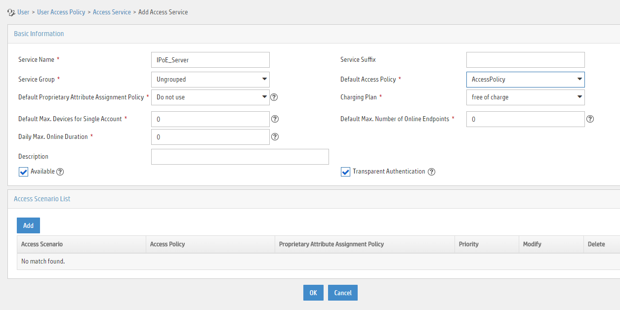
a. Add a user:
- Select User Management > Add User from the navigation tree to open the adding user page, as shown in Figure 230.
- Enter the username IPoE_Web001 and the user ID 001.
- Click OK.

a. Add an access user:
- Select Access User > All Access Users from the navigation tree to open the access user page
- Click Add to open the page as shown in Figure 231.
- Select IPoE_Web001 for the username.
- Enter the account name user1.
- Enter the password pass1.
- Select the access service IPoE_Server.
Figure 231 Adding an access user

5. Configure the portal server:
a. Configure the portal homepage:
- Select User Access Policy > Portal Service > Server from the navigation tree to open the portal server configuration page, as shown in Figure 232.
- Click OK.
Figure 232 Portal server configuration page

a. Configure portal authentication source IP address range:
- Select User Access Policy > Portal Service > IP Group from the navigation tree to open the portal IP address group configuration page.
- Click Add to open the page as shown in Figure 233.
- Enter the IP group name IPoE_Web_User.
- Enter the start IP address (192.168.0.1) and end IP address (192.168.0.255) of the IP group. Make sure the host IP address is in the IP group.
- Click OK.
Figure 233 Adding an IP address group

a. Add a portal device:
- Select User Access Policy > Portal Service > Device from the navigation tree to open the portal device configuration page.
- Click Add.
- Enter the device name NAS.
- Enter the IP address of the portal packets' outgoing interface Ten-GigabitEthernet 3/1/2 (12.1.1.1).
- Enter the key 123456
- Select Directly Connect for access method.
- Click OK.
b. Associate the portal device with the IP address group:
- Click the icon in the Port Group Information Management column of device NAS to open the port group configuration page, as shown in Figure 234.
- Click Add to open the page as shown in Figure 235.
- Enter the port group name group.
- Select the configured IP address group IPoE_Web_User. Make sure the IP address used by the user to access the network is within this IP address group.
- Select Supported in the Transparent Authentication list.
- Click OK.

Figure 235 Port group configuration
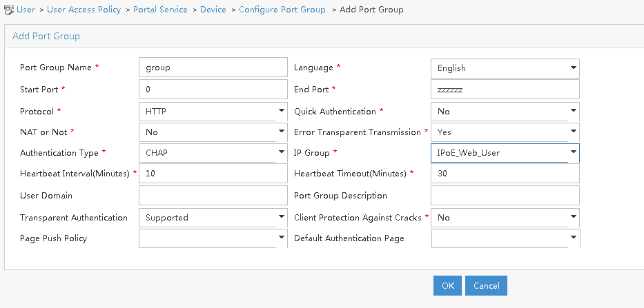
a. From the navigation tree, select User Access Manager > Service Parameters > Validate System Configuration to validate the settings.
Verifying the configuration
# Display IPoE session information to verify that the host has passed preauthentication.
[CP] display access-user auth-type pre-auth interface remote-xge 1024/3/1/2
Slot 97:
UserID Interface IP address MAC address S-/C-VLAN
Username IPv6 address Access type
0x33d R-XGE1024/3/1/2 192.168.0.2 0015-e947-f4d4 -/-
0015e947f4d4 - L2 IPoE dynamic
As shown in Figure 236, the Web login page opens after preauthentication. Enter the username and password on the page.

# Display IPoE session information to verify that the host has passed Web authentication and come online.
[CP] display access-user auth-type web-auth interface remote-xge 1024/3/1/2
Slot 97:
UserID Interface IP address MAC address S-/C-VLAN
Username IPv6 address Access type
0x33d R-XGE1024/3/1/2 192.168.0.2 0015-e947-f4d4 -/-
user1@dm2 - Web auth
# Click Log Out on the Web login page as shown in Figure 236.
# Verify that the user returns to the preauthentication status.
[CP] display access-user auth-type pre-auth interface remote-xge 1024/3/1/2
Slot 97:
UserID Interface IP address MAC address S-/C-VLAN
Username IPv6 address Access type
0x33d R-XGE1024/3/1/2 192.168.0.2 0015-e947-f4d4 -/-
0015e947f4d4 - L2 IPoE dynamic
# Open the browser, and enter an address randomly, for example, http://63.1.1.240.
# Verify that the user has come online through IPoE Web authentication.
[CP] display access-user auth-type web-auth interface remote-xge 1024/3/1/2
Slot 97:
UserID Interface IP address MAC address S-/C-VLAN
Username IPv6 address Access type
0x33d R-XGE1024/3/1/2 192.168.0.2 0015-e947-f4d4 -/-
0015e947f4d4 - Web auth
Example: Configuring IPoE common transparent MAC authentication (Layer 2 transparent)
Network configuration
As shown in Figure 237, the host accesses the BRAS as a DHCP client though a Layer 2 device. It obtains configuration information from the DHCP server through the BRAS. The BRAS performs AAA for the host through the RADIUS server. A server installed with H3C IMC acts as the portal authentication server and the portal Web server. This example uses IMC PLAT 7.1(E0303), IMC UAM 7.1(E0305), and IMC EIP 7.1(E0305). The RADIUS server supports MAC binding, acts as the authentication, authorization, and accounting server, and performs MAC binding. The FTP server is an internal network server.
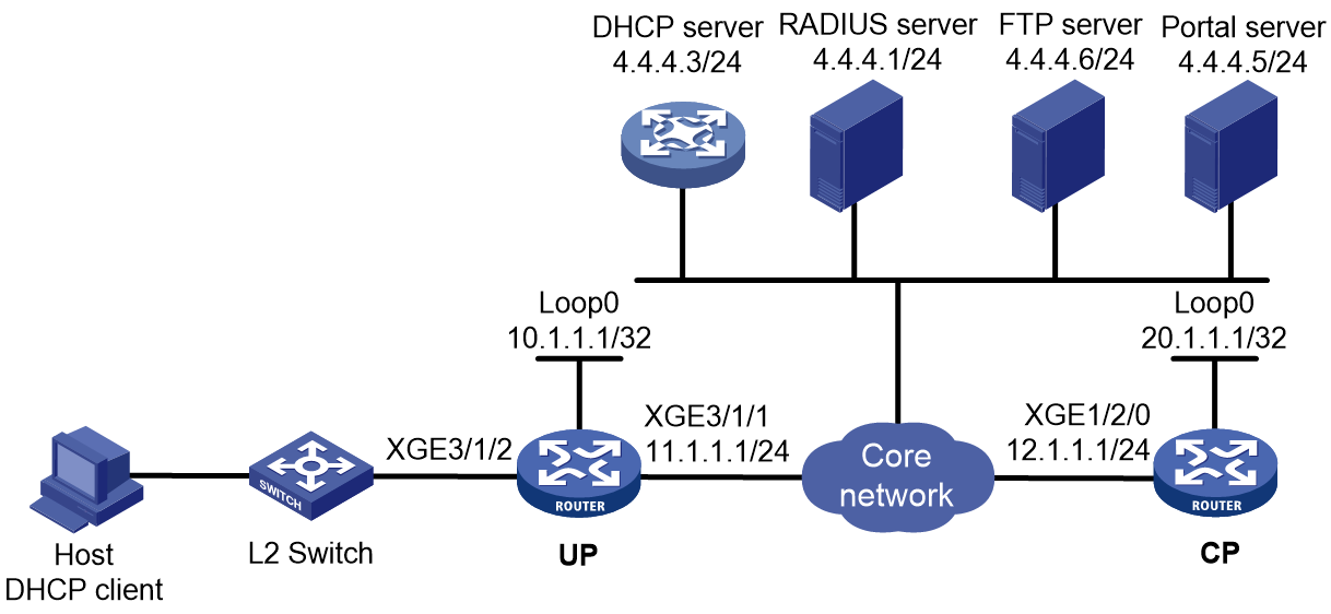
Prerequisites
Configure IP addresses for interfaces, and make sure devices can reach each other at Layer 3. (Details not shown.)
Set up the management channel, control channel, and protocol channel between the CP and UP. (Details not shown.)
Procedure
1. Configure the DHCP server:
# Enable DHCP.
<DHCP-server> system-view
[DHCP-server] dhcp enable
# Enable the DHCP server to return a DHCP-NAK message if the client notions of their IP addresses are incorrect.
[DHCP-server] dhcp server request-ip-address check
# Create an IP address pool named pool1 and enter its view.
[DHCP-server] ip pool pool1
# Specify primary subnet 192.168.0.0/24 for dynamic allocation in address pool pool1.
[DHCP-server-ip-pool-pool1] network 192.168.0.0 24
# Specify gateway address 192.168.0.1 in address pool pool1.
[DHCP-server-ip-pool-pool1] gateway-list 192.168.0.1
# Specify DNS server address 8.8.8.8 in address pool pool1.
[DHCP-server-ip-pool-pool1] dns-list 8.8.8.8
# Exclude IP address 192.168.0.1 from dynamic allocation in address pool pool1.
[DHCP-server-ip-pool-pool1] forbidden-ip 192.168.0.1
[DHCP-server-ip-pool-pool1] quit
# Configure the default route to the CP.
[DHCP-server] ip route-static 0.0.0.0 0 12.1.1.1
2. Configure the UP:
a. Configure the UP to operate in user plane mode.
<UP> system-view
[UP] work-mode user-plane
b. Specify 11111 as the HTTPS redirect listening port number. Make sure the port number is not used by any other service. To see the TCP port numbers used by other services, execute the display tcp command.
[UP] http-redirect https-port 11111
c. Create a local user group named pre.
[UP] user-group pre
New user group added.
[UP-ugroup-pre] quit
d. Configure ACLs for preauthentication:
# Create an IPv4 advanced ACL named web_permit. Configure a rule to permit all packets destined for the portal server from users in user group pre.
[UP] acl advanced name web_permit
[UP-acl-ipv4-adv-web_permit] rule 0 permit ip destination 4.4.4.5 0 user-group pre
[UP-acl-ipv4-adv-web_permit] quit
# Create an IPv4 advanced ACL named neiwang. Configure a rule to permit all packets destined for the internal network server from users in user group pre.
[UP] acl advanced name neiwang
[UP-acl-ipv4-adv-neiwang] rule 0 permit ip destination 4.4.4.6 0 user-group pre
[UP-acl-ipv4-adv-neiwang] quit
# Create an IPv4 advanced ACL named web_http. Configure a rule to permit TCP packets with the destination port 80 (HTTP packets) from users in user group pre.
[UP] acl advanced name web_http
[UP-acl-ipv4-adv-web_http] rule 0 permit tcp destination-port eq www user-group pre
[UP-acl-ipv4-adv-web_http] quit
# Create an IPv4 advanced ACL named web_https, and configure a rule to permit TCP packets with the destination port 443 (HTTPS packets) from users in user group pre.
[UP] acl advanced name web_https
[UP-acl-ipv4-adv-web_https] rule 0 permit tcp destination-port eq 443 user-group pre
[UP-acl-ipv4-adv-web_https] quit
# Create an IPv4 advanced ACL named ip, and configure a rule to permit IP packets from users in user group pre.
[UP] acl advanced name ip
[UP-acl-ipv4-adv-ip] rule 0 permit ip user-group pre
[UP-acl-ipv4-adv-ip] quit
# Create an IPv4 advanced ACL named neiwang_out, and configure a rule to permit IP packets from the internal network server in user group pre.
[UP] acl advanced name neiwang_out
[UP-acl-ipv4-adv-neiwang_out] rule 0 permit ip source 4.4.4.6 0 user-group pre
[UP-acl-ipv4-adv-neiwang_out] quit
# Create an IPv4 advanced ACL named web_out, and configure a rule to permit IP packets from the portal server in user group pre.
[UP] acl advanced name web_out
[UP-acl-ipv4-adv-web_out] rule 0 permit ip source 4.4.4.5 0 user-group pre
[UP-acl-ipv4-adv-web_out] quit
e. Configure QoS traffic classes for preauthentication users:
# Create the traffic class web_permit and specify ACL web_permit as the match criterion.
[UP] traffic classifier web_permit operator and
[UP-classifier-web_permit] if-match acl name web_permit
[UP-classifier-web_permit] quit
# Create the traffic class neiwang and specify ACL neiwang as the match criterion.
[UP] traffic classifier neiwang operator and
[UP-classifier-neiwang] if-match acl name neiwang
[UP-classifier-neiwang] quit
# Create the traffic class web_http and specify ACL web_http as the match criterion.
[UP] traffic classifier web_http operator and
[UP-classifier-web_http] if-match acl name web_http
[UP-classifier-web_http] quit
# Create the traffic class web_https and specify ACL web_https as the match criterion.
[UP] traffic classifier web_https operator and
[UP-classifier-web_https] if-match acl name web_https
[UP-classifier-web_https] quit
# Create the traffic class ip_cpu and specify ACL ip as the match criterion.
[UP] traffic classifier ip_cpu operator and
[UP-classifier-ip_cpu] if-match acl name ip
[UP-classifier-ip_cpu] quit
# Create the traffic class ip_deny and specify ACL ip as the match criterion.
[UP] traffic classifier ip_deny operator and
[UP-classifier-ip_deny] if-match acl name ip
[UP-classifier-ip_deny] quit
# Create the traffic class neiwang_out and specify ACL neiwang_out as the match criterion.
[UP] traffic classifier neiwang_out operator and
[UP-classifier-neiwang_out] if-match acl name neiwang_out
[UP-classifier-neiwang_out] quit
# Create the traffic class web_out and specify ACL web_out as the match criterion.
[UP] traffic classifier web_out operator and
[UP-classifier-web_out] if-match acl name web_out
[UP-classifier-web_out] quit
f. Configure QoS traffic behaviors:
# Configure the traffic behavior web_permit to permit traffic to pass through without rate limiting or accounting.
[UP] traffic behavior web_permit
[UP-behavior-web_permit] filter permit
[UP-behavior-web_permit] free account
[UP-behavior-web_permit] quit
# Configure the traffic behavior neiwang to permit traffic to pass through.
[UP] traffic behavior neiwang
[UP-behavior-neiwang] filter permit
[UP-behavior-neiwang] quit
# Configure the traffic behavior web_http to redirect HTTP packets to the CPU.
[UP] traffic behavior web_http
[UP-behavior-web_http] redirect http-to-cpu
[UP-behavior-web_http] quit
# Configure the traffic behavior web_https to redirect HTTPS packets to the CPU.
[UP] traffic behavior web_https
[UP-behavior-web_https] redirect https-to-cpu
[UP-behavior-web_https] quit
# Configure the traffic behavior web_deny to deny traffic.
[UP] traffic behavior web_deny
[UP-behavior-web_deny] filter deny
[UP-behavior-web_deny] free account
[UP-behavior-web_deny] quit
# Configure the traffic behavior neiwang_out to permit traffic to pass through.
[UP] traffic behavior neiwang_out
[UP-behavior-neiwang_out] filter permit
[UP-behavior-neiwang_out] quit
# Configure the traffic behavior web_out to permit traffic without rate limiting or traffic accounting.
[UP] traffic behavior web_out
[UP-behavior-web_out] filter permit
[UP-behavior-web_out] free account
[UP-behavior-web_out] quit
g. Configure the QoS policies:
# Create a QoS policy named web.
[UP] qos policy web
# Associate the traffic class web_permit with the traffic behavior web_permit.
[UP-qospolicy-web] classifier web_permit behavior web_permit
# Associate the traffic class neiwang with the traffic behavior neiwang.
[UP-qospolicy-web] classifier neiwang behavior neiwang
# Associate the traffic class web_http with the traffic behavior web_http.
[UP-qospolicy-web] classifier web_http behavior web_http
# Associate the traffic class web_https with the traffic behavior web_https.
[UP-qospolicy-web] classifier web_https behavior web_https
# Associate the traffic class ip_cpu with the traffic behavior web_cpu.
[UP-qospolicy-web] classifier ip_cpu behavior web_cpu
# Associate the traffic class ip_deny with the traffic behavior web_deny.
[UP-qospolicy-web] classifier ip_deny behavior web_deny
[UP-qospolicy-web] quit
# Configure a QoS policy named out.
[UP] qos policy out
# Associate the traffic class web_out with the traffic behavior web_out. Associate the traffic class neiwang_out with the traffic behavior neiwang_out. Associate the traffic class web_deny with the traffic behavior web_deny.
[UP-qospolicy-out] classifier web_out behavior web_out
[UP-qospolicy-out] classifier neiwang_out behavior neiwang_out
[UP-qospolicy-out] classifier ip_deny behavior web_deny
[UP-qospolicy-out] quit
h. Apply the QoS policies:
# Apply the QoS Policy web to the inbound traffic globally. To identify whether the QoS policy takes effect, execute the display qos policy global inbound command.
[UP] qos apply policy web global inbound
# Apply the QoS Policy out to the outbound traffic globally. To identify whether the QoS policy takes effect, execute the display qos policy global outbound command.
[UP] qos apply policy out global outbound
3. Configure the CP:
a. Configure the DHCP relay agent:
# Enable the DHCP relay agent on Remote-XGE 1024/3/1/2.
<CP> system-view
[CP] interface remote-xge 1024/3/1/2
[CP–Remote-XGE1024/3/1/2] dhcp select relay
[CP–Remote-XGE1024/3/1/2] quit
# Create a remote BAS IP address pool named pool1 for the DHCP relay agent.
[CP] ip pool pool1 bas remote
# Specify gateway address 192.168.0.1 in address pool pool1.
[CP-ip-pool-pool1] gateway 192.168.0.1 24
# Exclude IP address 192.168.0.1 from dynamic allocation in address pool pool1.
[CP-ip-pool-pool1] forbidden-ip 192.168.0.1
# Specify DHCP server 4.4.4.3 in address pool pool1, and bind the address pool to UP 1024.
[CP-ip-pool-pool1] remote-server 4.4.4.3
[CP-ip-pool-pool1] binding up-id 1024
[CP-ip-pool-pool1] quit
b. Configure the IP address of the portal authentication server newpt as 4.4.4.5 and the plaintext key 123456.
[CP] portal server newpt
[CP-portal-server-newpt] ip 4.4.4.5 key simple 123456
[CP-portal-server-newpt] quit
c. Configure the CP to get user access information from ARP and ND entries.
[CP] portal access-info trust arp
[CP] portal access-info trust nd
d. Create a local user group named pre.
[CP] user-group pre
New user group added.
[CP-ugroup-pre] quit
e. Configure a RADIUS scheme:
# Create a RADIUS scheme named rs1 and enter its view.
[CP] radius scheme rs1
# Configure primary servers and keys for authentication and accounting.
[CP-radius-rs1] primary authentication 4.4.4.1
[CP-radius-rs1] primary accounting 4.4.4.1
[CP-radius-rs1] key authentication simple radius
[CP-radius-rs1] key accounting simple radius
# Exclude the ISP name from the username sent to the RADIUS server.
[CP-radius-rs1] user-name-format without-domain
[CP-radius-rs1] quit
f. Configure the preauthentication ISP domain and Web authentication ISP domain:
# Configure the ISP domain dm1 for IPoE user preauthentication.
[CP] domain name dm1
[CP-isp-dm1] authentication ipoe none
[CP-isp-dm1] authorization ipoe none
[CP-isp-dm1] accounting ipoe none
# Configure the authorized IP address pool and user group in ISP domain dm1.
[CP-isp-dm1] authorization-attribute user-group pre
[CP-isp-dm1] authorization-attribute ip-pool pool1
# Configure the Web authentication page URL in ISP domain dm1.
[CP-isp-dm1] web-server url http://4.4.4.5:8080/portal/
[CP-isp-dm1] quit
# Configure the ISP domain dm2 for IPoE user Web authentication.
[CP] domain name dm2
[CP-isp-dm2] authentication ipoe radius-scheme rs1
[CP-isp-dm2] authorization ipoe radius-scheme rs1
[CP-isp-dm2] accounting ipoe radius-scheme rs1
[CP-isp-dm2] quit
g. Configure IPoE:
# Enable IPoE and configure Layer 2 access mode on Remote-XGE 1024/3/1/2.
[CP] interface remote-xge 1024/3/1/2
[CP–Remote-XGE1024/3/1/2] ip subscriber l2-connected enable
# Configure Web MAC authentication for IPoE users on Remote-XGE 1024/3/1/2.
[CP–Remote-XGE1024/3/1/2] ip subscriber authentication-method web mac-auth
The operation may cut all users on this interface. Continue?[Y/N]:y
# Configure the ISP domain dm1 for preauthentication and the ISP domain dm2 for Web authentication on Remote-XGE 1024/3/1/2.
[CP–Remote-XGE1024/3/1/2] ip subscriber pre-auth domain dm1
[CP–Remote-XGE1024/3/1/2] ip subscriber web-auth domain dm2
[CP–Remote-XGE1024/3/1/2] quit
4. Configure the RADIUS server.
For more information about configuring AAA and MAC binding on the RADIUS server, see the configuration guide for the RADIUS server.
5. Configure the portal server:
a. Configure the portal homepage:
- Select User Access Policy > Portal Service > Server from the navigation tree to open the portal server configuration page, as shown in Figure 238.
- Click OK.
Figure 238 Portal server configuration page

a. Configure portal authentication source IP address range:
- Select User Access Policy > Portal Service > IP Group from the navigation tree to open the portal IP address group configuration page.
- Click Add to open the page as shown in Figure 239.
- Enter the IP group name IPoE_Web_User.
- Enter the start IP address (192.168.0.1) and end IP address (192.168.0.255) of the IP group. Make sure the host IP address is in the IP group.
- Click OK.
Figure 239 Adding an IP address group

a. Add a portal device:
- Select User Access Policy > Portal Service > Device from the navigation tree to open the portal device configuration page.
- Click Add.
- Enter the device name NAS.
- Enter the IP address of the portal packets' outgoing interface Ten-GigabitEthernet 3/1/2 (12.1.1.1).
- Enter the key 123456.
- Select Directly Connect for access method.
- Click OK.
b. Associate the portal device with the IP address group:
- Click the icon in the Port Group Information Management column of device NAS to open the port group configuration page, as shown in Figure 240.
- Click Add to open the page as shown in Figure 241.
- Enter the port group name group.
- Select the configured IP address group IPoE_Web_User. Make sure the IP address used by the user to access the network is within this IP address group.
- Click OK.

Figure 241 Port group configuration

Verifying the configuration
# Display IPoE session information to verify that the host has passed preauthentication.
[CP] display access-user auth-type pre-auth interface remote-xge 1024/3/1/2
Slot 97:
UserID Interface IP address MAC address S-/C-VLAN
Username IPv6 address Access type
0x33d R-XGE1024/3/1/2 192.168.0.2 0015-e947-f4d4 -/-
0015e947f4d4 - L2 IPoE dynamic
As shown in Figure 242, the Web login page opens after preauthentication. Enter the username and password on the page.
# Display IPoE session information to verify that the host has passed Web authentication and come online.
[CP] display access-user auth-type web-auth interface remote-xge 1024/3/1/2
Slot 97:
UserID Interface IP address MAC address S-/C-VLAN
Username IPv6 address Access type
0x33d R-XGE1024/3/1/2 192.168.0.2 0015-e947-f4d4 -/-
user1@dm2 - Web auth
# Click Log Out on the page as shown in Figure 242.
# Verify that the user returns to the preauthentication status.
[CP] display access-user auth-type pre-auth interface remote-xge 1024/3/1/2
Slot 97:
UserID Interface IP address MAC address S-/C-VLAN
Username IPv6 address Access type
0x33d R-XGE1024/3/1/2 192.168.0.2 0015-e947-f4d4 -/-
0015e947f4d4 - L2 IPoE dynamic
# Open the browser, and enter any address in the address bar to access http://63.1.1.240/. Display session information. The output shows that the user has come online through Web authentication.
[CP] display access-user auth-type web-auth interface remote-xge 1024/3/1/2
Slot 97:
UserID Interface IP address MAC address S-/C-VLAN
Username IPv6 address Access type
0x33d R-XGE1024/3/1/2 192.168.0.2 0015-e947-f4d4 -/-
0015e947f4d4 - Web auth
Example: Configuring IPoE common transparent MAC authentication for dual-stack users
Network configuration
As shown in Figure 243, the host accesses the BRAS as a DHCP client though a Layer 2 device. It obtains configuration information from the DHCP server through the BRAS. The BRAS performs AAA for the host through the RADIUS server. A server installed with H3C IMC acts as the portal authentication server and the portal Web server. This example uses IMC PLAT 7.1(E0303), IMC UAM 7.1(E0305), and IMC EIP 7.1(E0305). A RADIUS server that supports MAC binding acts as the authentication, authorization, and accounting server and performs MAC binding. The FTP server is an internal network server. Limit the access rate to 5 Mbps for the user after passing Web authentication.
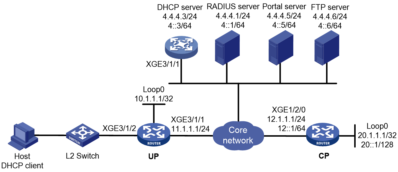
Prerequisites
Configure IP addresses for interfaces, and make sure devices can reach each other at Layer 3. (Details not shown.)
Set up the management channel, control channel, and protocol channel between the CP and UP. (Details not shown.)
Configure the DNS server properly, so that the server can parse the IPv4 URL or IPv6 URL corresponding to the Web authentication page http://www.ipv4.web.com (or http://www.ipv6.web.com) according to the first protocol stack that comes online of the IPoE dual-stack user. (Details not shown.)
Procedure
1. Configure the DHCP servers:
a. Configure an IP address pool:
# Enable DHCP.
<DHCP-server> system-view
[DHCP-server] dhcp enable
# Enable the DHCP server to return a DHCP-NAK message if the client notions of their IP addresses are incorrect.
[DHCP-server] dhcp server request-ip-address check
# Create an IP address pool named pool1 and enter its view.
[DHCP-server] ip pool pool1
# Specify primary subnet 192.168.0.0/24 for dynamic allocation and DNS server 8.8.8.8 in address pool pool1.
[DHCP-server-ip-pool-pool1] network 192.168.0.0 24
[DHCP-server-ip-pool-pool1] dns-list 8.8.8.8
# Specify gateway address 192.168.0.1 in address pool pool1.
[DHCP-server-ip-pool-pool1] gateway-list 192.168.0.1
# Exclude IP address 192.168.0.1 from dynamic allocation in address pool pool1.
[DHCP-server-ip-pool-pool1] forbidden-ip 192.168.0.1
[DHCP-server-ip-pool-pool1] quit
# Configure the default route to the CP.
[DHCP-server] ip route-static 0.0.0.0 0 12.1.1.1
b. Configure an IPv6 address pool:
# Create an IPv6 address pool named pool2 and enter its view.
[DHCP-server] ipv6 pool pool2
# Specify primary subnet 192::/64 for dynamic allocation and DNS server 8::8 in address pool pool2.
[DHCP-server-ipv6-pool-pool2] network 192::/64
[DHCP-server-ipv6-pool-pool2] dns-server 8::8
[DHCP-server-ipv6-pool-pool2] quit
# Exclude IP address 192::1 from dynamic allocation in address pool pool2.
[DHCP-server] ipv6 dhcp server forbidden-address 192::1
# Enable the DHCPv6 server on Ten-GigabitEthernet 3/1/1.
[DHCP-server] interface ten-gigabitethernet 3/1/1
[DHCP-server-Ten-GigabitEthernet3/1/1] ipv6 dhcp select server
[DHCP-server-Ten-GigabitEthernet3/1/1] quit
# Configure the default route to the CP.
[DHCP-server] ipv6 route-static :: 0 12::1
2. Configure the UP:
a. Configure the UP to operate in user plane mode.
<UP> system-view
[UP] work-mode user-plane
b. Specify 11111 as the HTTPS redirect listening port number. Make sure the port number is not used by any other service. To see the TCP port numbers used by other services, execute the display tcp command.
[UP] http-redirect https-port 11111
c. Create a local user group named pre.
[UP] user-group pre
New user group added.
[UP-ugroup-pre] quit
d. Configure ACLs for preauthentication:
# Create an IPv4 and IPv6 advanced ACL named web_permit separately. Configure a rule to permit all packets destined for the portal server from users in user group pre.
[UP] acl advanced name web_permit
[UP-acl-ipv4-adv-web_permit] rule 0 permit ip destination 4.4.4.5 0 user-group pre
[UP-acl-ipv4-adv-web_permit] quit
[UP] acl ipv6 advanced name web_permit
[UP-acl-ipv6-adv-web_permit] rule 0 permit ipv6 destination 4::5 128 user-group pre
[UP-acl-ipv6-adv-web_permit] quit
# Create an IPv4 and IPv6 advanced ACL named neiwang separately. Configure a rule to permit all packets destined for the internal network server from users in user group pre.
[UP] acl advanced name neiwang
[UP-acl-ipv4-adv-neiwang] rule 0 permit ip destination 4.4.4.6 0 user-group pre
[UP-acl-ipv4-adv-neiwang] quit
[UP] acl ipv6 advanced name neiwang
[UP-acl-ipv6-adv-neiwang] rule 0 permit ipv6 destination 4::6 128 user-group pre
[UP-acl-ipv6-adv-neiwang] quit
# Create an IPv4 and IPv6 advanced ACL named web_http separately. Configure a rule to permit TCP packets with the destination port 80 (HTTP packets) from users in user group pre.
[UP] acl advanced name web_http
[UP-acl-ipv4-adv-web_http] rule 0 permit tcp destination-port eq www user-group pre
[UP-acl-ipv4-adv-web_http] quit
[UP] acl ipv6 advanced name web_http
[UP-acl-ipv6-adv-web_http] rule 0 permit tcp destination-port eq www user-group pre
[UP-acl-ipv6-adv-web_http] quit
# Create an IPv4 and IPv6 advanced ACL named web_https separately, and configure a rule to permit TCP packets with the destination port 443 (HTTPS packets) from users in user group pre.
[UP] acl advanced name web_https
[UP-acl-ipv4-adv-web_https] rule 0 permit tcp destination-port eq 443 user-group pre
[UP-acl-ipv4-adv-web_https] quit
[UP] acl ipv6 advanced name web_https
[UP-acl-ipv6-adv-web_https] rule 0 permit tcp destination-port eq 443 user-group pre
[UP-acl-ipv6-adv-web_https] quit
# Create an IPv4 and IPv6 advanced ACL named ip separately, and configure a rule to permit IP packets from users in user group pre.
[UP] acl advanced name ip
[UP-acl-ipv4-adv-ip] rule 0 permit ip user-group pre
[UP-acl-ipv4-adv-ip] quit
[UP] acl ipv6 advanced name ip
[UP-acl-ipv6-adv-ip] rule 0 permit ipv6 user-group pre
[UP-acl-ipv6-adv-ip] quit
# Create an IPv4 and IPv6 advanced ACL named neiwang_out separately, and configure a rule to permit IP packets from the internal network server in user group pre.
[UP] acl advanced name neiwang_out
[UP-acl-ipv4-adv-neiwang_out] rule 0 permit ip source 4.4.4.6 0 user-group pre
[UP-acl-ipv4-adv-neiwang_out] quit
[UP] acl ipv6 advanced name neiwang_out
[UP-acl-ipv6-adv-neiwang_out] rule 0 permit ipv6 source 4::6 128 user-group pre
[UP-acl-ipv6-adv-neiwang_out] quit
# Create an IPv4 and IPv6 advanced ACL named web_out separately, and configure a rule to permit IP packets from the portal server in user group pre.
[UP] acl advanced name web_out
[UP-acl-ipv4-adv-web_out] rule 0 permit ip source 4.4.4.5 0 user-group pre
[UP-acl-ipv4-adv-web_out] quit
[UP] acl ipv6 advanced name web_out
[UP-acl-ipv6-adv-web_out] rule 0 permit ipv6 source 4::5 128 user-group pre
[UP-acl-ipv6-adv-web_out] quit
e. Configure QoS traffic classes for preauthentication users:
# Create the traffic class web_permit and specify ACL web_permit as the match criterion.
[UP] traffic classifier web_permit operator or
[UP-classifier-web_permit] if-match acl name web_permit
[UP-classifier-web_permit] if-match acl ipv6 name web_permit
[UP-classifier-web_permit] quit
# Create the traffic class neiwang and specify ACL neiwang as the match criterion.
[UP] traffic classifier neiwang operator or
[UP-classifier-neiwang] if-match acl name neiwang
[UP-classifier-neiwang] if-match acl ipv6 name neiwang
[UP-classifier-neiwang] quit
# Create the traffic class web_http and specify ACL web_http as the match criterion.
[UP] traffic classifier web_http operator or
[UP-classifier-web_http] if-match acl name web_http
[UP-classifier-web_http] if-match acl ipv6 name web_http
[UP-classifier-web_http] quit
# Create the traffic class web_https and specify ACL web_https as the match criterion.
[UP] traffic classifier web_https operator or
[UP-classifier-web_https] if-match acl name web_https
[UP-classifier-web_https] if-match acl ipv6 name web_https
[UP-classifier-web_https] quit
# Create the traffic class ip_cpu and specify ACL ip as the match criterion.
[UP] traffic classifier ip_cpu operator or
[UP-classifier-ip_cpu] if-match acl name ip
[UP-classifier-ip_cpu] if-match acl ipv6 name ip
[UP-classifier-ip_cpu] quit
# Create the traffic class ip_deny and specify ACL ip as the match criterion.
[UP] traffic classifier ip_deny operator or
[UP-classifier-ip_deny] if-match acl name ip
[UP-classifier-ip_deny] if-match acl ipv6 name ip
[UP-classifier-ip_deny] quit
# Create the traffic class neiwang_out and specify ACL neiwang_out as the match criterion.
[UP] traffic classifier neiwang_out operator or
[UP-classifier-neiwang_out] if-match acl name neiwang_out
[UP-classifier-neiwang_out] if-match acl ipv6 name neiwang_out
[UP-classifier-neiwang_out] quit
# Create the traffic class web_out and specify ACL web_out as the match criterion.
[UP] traffic classifier web_out operator or
[UP-classifier-web_out] if-match acl name web_out
[UP-classifier-web_out] if-match acl ipv6 name web_out
[UP-classifier-web_out] quit
f. Configure QoS traffic behaviors:
# Configure the traffic behavior web_permit to permit traffic to pass through without rate limiting or accounting.
[UP] traffic behavior web_permit
[UP-behavior-web_permit] filter permit
[UP-behavior-web_permit] free account
[UP-behavior-web_permit] quit
# Configure the traffic behavior neiwang to permit traffic to pass through.
[UP] traffic behavior neiwang
[UP-behavior-neiwang] filter permit
[UP-behavior-neiwang] quit
# Configure the traffic behavior web_http to redirect HTTP packets to the CPU.
[UP] traffic behavior web_http
[UP-behavior-web_http] redirect http-to-cpu
[UP-behavior-web_http] quit
# Configure the traffic behavior web_https to redirect HTTPS packets to the CPU.
[UP] traffic behavior web_https
[UP-behavior-web_https] redirect https-to-cpu
[UP-behavior-web_https] quit
# Configure the traffic behavior web_cpu to redirect IP packets to the CPU.
[UP] traffic behavior web_cpu
[UP-behavior-web_cpu] redirect cpu
[UP-behavior-web_cpu] quit
# Configure the traffic behavior web_deny to deny traffic.
[UP] traffic behavior web_deny
[UP-behavior-web_deny] filter deny
[UP-behavior-web_deny] free account
[UP-behavior-web_deny] quit
# Configure the traffic behavior neiwang_out to permit traffic to pass through.
[UP] traffic behavior neiwang_out
[UP-behavior-neiwang_out] filter permit
[UP-behavior-neiwang_out] quit
# Configure the traffic behavior web_out to permit traffic without rate limiting or traffic accounting.
[UP] traffic behavior web_out
[UP-behavior-web_out] filter permit
[UP-behavior-web_out] free account
[UP-behavior-web_out] quit
g. Configure the QoS policies:
# Create a QoS policy named web.
[UP] qos policy web
# Associate the traffic class web_permit with the traffic behavior web_permit.
[UP-qospolicy-web] classifier web_permit behavior web_permit
# Associate the traffic class neiwang with the traffic behavior neiwang.
[UP-qospolicy-web] classifier neiwang behavior neiwang
# Associate the traffic class web_http with the traffic behavior web_http.
[UP-qospolicy-web] classifier web_http behavior web_http
# Associate the traffic class web_https with the traffic behavior web_https.
[UP-qospolicy-web] classifier web_https behavior web_https
# Associate the traffic class ip_cpu with the traffic behavior web_cpu.
[UP-qospolicy-web] classifier ip_cpu behavior web_cpu
# Associate the traffic class ip_deny with the traffic behavior web_deny.
[UP-qospolicy-web] classifier ip_deny behavior web_deny
[UP-qospolicy-web] quit
# Configure a QoS policy named out.
[UP] qos policy out
# Associate the traffic class web_out with the traffic behavior web_out. Associate the traffic class neiwang_out with the traffic behavior neiwang_out. Associate the traffic class web_deny with the traffic behavior web_deny.
[UP-qospolicy-out] classifier web_out behavior web_out
[UP-qospolicy-out] classifier neiwang_out behavior neiwang_out
[UP-qospolicy-out] classifier ip_deny behavior web_deny
[UP-qospolicy-out] quit
h. Apply the QoS policies:
# Apply the QoS Policy web to the inbound traffic globally. To identify whether the QoS policy takes effect, execute the display qos policy global inbound command.
[UP] qos apply policy web global inbound
# Apply the QoS Policy out to the outbound traffic globally. To identify whether the QoS policy takes effect, execute the display qos policy global outbound command.
[UP] qos apply policy out global outbound
3. Configure the CP:
a. Configure the DHCP relay agent:
# Create a remote BAS IP address pool named pool1.
<CP> system-view
[CP] ip pool pool1 bas remote
[CP-ip-pool-pool1] gateway 192.168.0.1 24
[CP-ip-pool-pool1] forbidden-ip 192.168.0.1
[CP-ip-pool-pool1] remote-server 4.4.4.3
[CP-ip-pool-pool1] binding up-id 1024
[CP-ip-pool-pool1] quit
# Create a remote IPv6 address pool named pool2.
[CP] ipv6 pool pool2 bas remote
[CP-ipv6-pool-pool2] gateway-list 192::1
[CP-ipv6-pool-pool2] network 192::/64 export-route
[CP-ipv6-pool-pool2] remote-server 4::3
[CP-ipv6-pool-pool2] dhcpv6-relay source-address interface loopback 0
[CP-ipv6-pool-pool2] binding up-id 1024
[CP-ipv6-pool-pool2] quit
# Enable the DHCPv4 relay agent on Remote-XGE 1024/3/1/2.
[CP] interface remote-xge 1024/3/1/2
[CP–Remote-XGE1024/3/1/2] dhcp select relay
# Automatically generate a link-local address for Remote-XGE 1024/3/1/2.
[CP–Remote-XGE1024/3/1/2] ipv6 address auto link-local
# Enable the DHCPv6 relay agent on Remote-XGE 1024/3/1/2.
[CP–Remote-XGE1024/3/1/2] ipv6 dhcp select relay
# Disable RA message suppression on Remote-XGE 1024/3/1/2.
[CP–Remote-XGE1024/3/1/2] undo ipv6 nd ra halt
# Set the managed address configuration flag (M) to 1 in RA advertisements to be sent. Then, the host uses a DHCPv6 server to obtain IPv6 addresses.
[CP–Remote-XGE1024/3/1/2] ipv6 nd autoconfig managed-address-flag
# Set the other stateful configuration flag (O) to 1 in RA advertisements to be sent. Then, the host uses a DHCPv6 server to obtain configuration information other than IPv6 addresses.
[CP–Remote-XGE1024/3/1/2] ipv6 nd autoconfig other-flag
# Disable Remote-XGE 1024/3/1/2 from advertising the specified prefix in RA messages, preventing the endpoint from obtaining a temporary IPv6 address. In an IPv6 network, an endpoint might use a temporary IPv6 address for IPoE Web authentication, which will cause authentication failure.
[CP–Remote-XGE1024/3/1/2] ipv6 nd ra prefix 192::/64 no-advertise
[CP–Remote-XGE1024/3/1/2] quit
b. Configure the portal servers:
# Configure the IP address of the IPv4 portal authentication server newpt1 as 4.4.4.5 and the plaintext key 123456.
[CP] portal server newpt1
[CP-portal-server-newpt1] ip 4.4.4.5 key simple 123456
[CP-portal-server-newpt1] quit
# Configure the IPv6 address of the IPv6 portal authentication server newpt2 as 4::5 and the plaintext key 123456.
[CP] portal server newpt2
[CP-portal-server-newpt2] ipv6 4::5 key simple 123456
[CP-portal-server-newpt2] quit
c. Configure the CP to get user access information from ARP and ND entries.
[CP] portal access-info trust arp
[CP] portal access-info trust nd
d. Create a local user group named pre.
[CP] user-group pre
New user group added.
[CP-ugroup-pre] quit
e. Configure a RADIUS scheme:
# Create a RADIUS scheme named rs1 and enter its view.
[CP] radius scheme rs1
# Configure primary servers and keys for authentication and accounting.
[CP-radius-rs1] primary authentication 4.4.4.1
[CP-radius-rs1] primary accounting 4.4.4.1
[CP-radius-rs1] key authentication simple radius
[CP-radius-rs1] key accounting simple radius
# Exclude the ISP name from the username sent to the RADIUS server.
[CP-radius-rs1] user-name-format without-domain
[CP-radius-rs1] quit
# Set the IP address of the RADIUS DAE client to 4.4.4.1, and set the shared key to radius for the RADIUS DAE client to exchange DAE packets.
[CP] radius dynamic-author server
[CP-radius-da-server] client ip 4.4.4.1 key simple radius
[CP-radius-da-server] quit
f. Configure the preauthentication ISP domain and Web authentication ISP domain:
# Configure the ISP domain dm1 for IPoE user preauthentication.
[CP] domain name dm1
[CP-isp-dm1] authentication ipoe none
[CP-isp-dm1] authorization ipoe none
[CP-isp-dm1] accounting ipoe none
# Configure the authorized user group and IP address pools in preauthentication ISP domain dm1.
[CP-isp-dm1] authorization-attribute user-group pre
[CP-isp-dm1] authorization-attribute ip-pool pool1
[CP-isp-dm1] authorization-attribute ipv6-pool pool2
# Configure the Web authentication page URL in ISP domain dm1.
[CP-isp-dm1] web-server url http://www.ipv4.web.com
[CP-isp-dm1] web-server ipv6-url http://www.ipv6.web.com
[CP-isp-dm1] quit
# Configure the ISP domain dm2 for IPoE user Web authentication.
[CP] domain name dm2
[CP-isp-dm2] authentication ipoe radius-scheme rs1
[CP-isp-dm2] authorization ipoe radius-scheme rs1
[CP-isp-dm2] accounting ipoe radius-scheme rs1
[CP-isp-dm2] authorization-attribute car inbound cir 5120 outbound cir 5120
[CP-isp-dm2] quit
g. Configure IPoE:
# Enable IPoE and configure Layer 2 access mode on Remote-XGE 1024/3/1/2.
[CP] interface remote-xge 1024/3/1/2
[CP–Remote-XGE1024/3/1/2] ip subscriber l2-connected enable
# Configure Web MAC authentication for IPoE users on Remote-XGE 1024/3/1/2.
[CP–Remote-XGE1024/3/1/2] ip subscriber authentication-method web mac-auth
The operation may cut all users on this interface. Continue?[Y/N]:y
# Configure the ISP domain dm1 for preauthentication and the ISP domain dm2 for Web authentication and Web MAC authentication on Remote-XGE 1024/3/1/2.
[CP–Remote-XGE1024/3/1/2] ip subscriber pre-auth domain dm1
[CP–Remote-XGE1024/3/1/2] ip subscriber web-auth domain dm2
[CP–Remote-XGE1024/3/1/2] ip subscriber mac-auth domain dm2
[CP–Remote-XGE1024/3/1/2] quit
4. Configure the RADIUS server.
For how to configure AAA and MAC binding on the RADIUS server, see the RADIUS server configuration guide.
5. Configure the portal server:
a. Configure the portal homepage:
- Select User Access Policy > Portal Service > Server from the navigation tree to open the portal server configuration page, as shown in Figure 244.
- Click OK.
Figure 244 Portal server configuration page
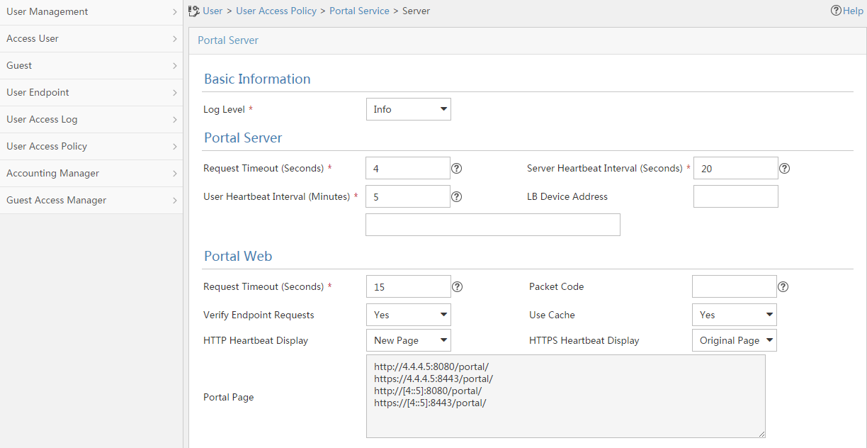
a. Configure portal authentication source IP address range:
- Select User Access Policy > Portal Service > IP Group from the navigation tree to open the portal IP address group configuration page.
- Click Add to open the page as shown in Figure 245.
- Enter the IP group name IPoE_Web_User.
- Enter the start IP address (192.168.0.1) and end IP address (192.168.0.255) of the IP group. Make sure the host IP address is in the IP group.
- Click OK.
Figure 245 Adding an IP address group (IPv4)

- Select User Access Policy > Portal Service > IP Group from the navigation tree to open the portal IP address group configuration page.
- Click Add to open the page as shown in Figure 246.
- Enter the IP group name IPoE_Web_User-2.
- Select Yes from the IPv6 list.
- Enter the start IP address (192::1) and end IP address (192::FFFF) of the IP group. Make sure the host IPv6 address is in the IP group.
- Click OK.
Figure 246 Adding an IP address group (IPv6)

a. Add a portal device:
- Select User Access Policy > Portal Service > Device from the navigation tree to open the portal device configuration page.
- Click Add.
- Enter the device name NAS.
- Enter the IP address of the portal packets' outgoing interface Ten-GigabitEthernet 3/1/2 (12.1.1.1).
- Enter the key 123456.
- Select Directly Connect for access method.
- Click OK.
- Select User Access Policy > Portal Service > Device from the navigation tree to open the portal device configuration page.
- Click Add.
- Enter the device name NAS-2.
- Select Portal 3.0 from the Version list.
- Enter the IP address of the portal packets' outgoing interface Ten-GigabitEthernet 3/1/2 (12::1).
- Enter the key 123456.
- Select Directly Connect for access method.
- Click OK.
b. Associate the portal device with the IP address group:
- Select User Access Policy > Portal Service > Device from the navigation tree to open the portal device configuration page.
- Click the icon in the Port Group Information Management column of device NAS to open the port group configuration page, as shown in Figure 247.
- Click Add to open the page as shown in Figure 248.
- Enter the port group name group.
- Select the configured IP address group IPoE_Web_User. Make sure the IP address used by the user to access the network is within this IP address group.
- Click OK.
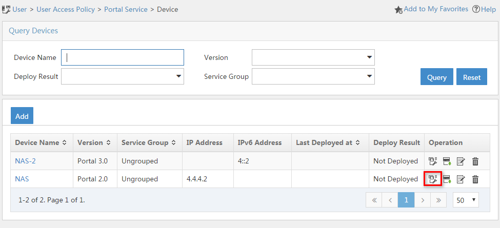
Figure 248 Port group configuration (IPv4)

- Select User Access Policy > Portal Service > Device from the navigation tree to open the portal device configuration page.
- Click the icon in the Port Group Information Management column of device NAS-2 to open the port group configuration page, as shown in Figure 247.
- Click Add to open the page as shown in Figure 249.
- Enter the port group name group-2.
- Select the configured IP address group IPoE_Web_User-2. Make sure the IPv6 address used by the user to access the network is within this IPv6 address group.
- Click OK.
Figure 249 Port group configuration (IPv6)
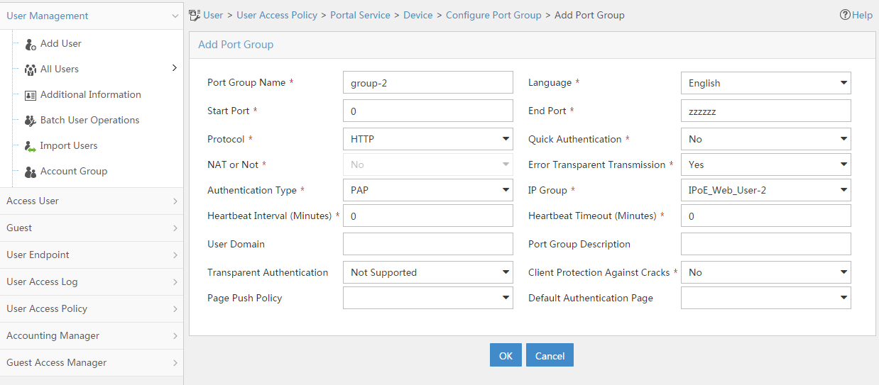
a. From the navigation tree, select User Access Manager > Service Parameters > Validate System Configuration to validate the settings.
Verifying the configuration
# Display IPoE session information to verify that the host has passed preauthentication and obtained IPv4 address 192.168.0.2 and IPv6 address 192::2.
[CP] display access-user auth-type pre-auth interface remote-xge 1024/3/1/2
Slot 97:
UserID Interface IP address MAC address S-/C-VLAN
Username IPv6 address Access type
0x33d R-XGE1024/3/1/2 192.168.0.2 0015-e947-f4d4 -/-
0015e947f4d4 192::2 L2 IPoE dynamic
As shown in Figure 250, the Web login page opens after preauthentication. Enter the username and password on the page.
# Display IPoE session information to verify that the host has passed Web authentication and come online.
[CP] display access-user auth-type web-auth interface remote-xge 1024/3/1/2
Slot 97:
UserID Interface IP address MAC address S-/C-VLAN
Username IPv6 address Access type
0x33d R-XGE1024/3/1/2 192.168.0.2 0015-e947-f4d4 -/-
user1@dm2 192::2 Web auth
# Click Log Out on the Web login page as shown in Figure 250.
# Verify that the user returns to the preauthentication status.
[CP] display access-user auth-type pre-auth interface remote-xge 1024/3/1/2
Slot 97:
UserID Interface IP address MAC address S-/C-VLAN
Username IPv6 address Access type
0x33d R-XGE1024/3/1/2 192.168.0.2 0015-e947-f4d4 -/-
0015e947f4d4 192::2 L2 IPoE dynamic
# Open the browser, and enter an address randomly, for example, http://63.1.1.240.
# Verify that the user has come online through IPoE Web MAC authentication.
[CP] display access-user auth-type web-auth interface remote-xge 1024/3/1/2
Slot 97:
UserID Interface IP address MAC address S-/C-VLAN
Username IPv6 address Access type
0x33d R-XGE1024/3/1/2 192.168.0.2 0015-e947-f4d4 -/-
0015e947f4d4 192::2 Web auth
Example: Configuring unclassified-IP packet initiation for global IPoE users (UP backup)
Network configuration
As shown in Figure 251:
· The host is assigned an IP address manually or through DHCP, and accesses the BRAS in IPoE mode through a Layer 3 network.
· Use the RADIUS server as the authentication, authorization, and accounting server. This section uses the Linux Free RADIUS server as an example.
· The BRAS supports CUPS for IPoE. Users are connected to UPs. The CP acts as the IPoE controller module.
· Normally, UP 1 acts as the master UP, and UP 2 acts as the backup UP. When Ten-GigabitEthernet3/1/1 on UP 1 fails, users that access through interface Ten-GigabitEthernet3/1/1 on UP 1 are automatically switched to interface Ten-GigabitEthernet3/1/1 on UP 2 to reduce the service interruption time at best effort.
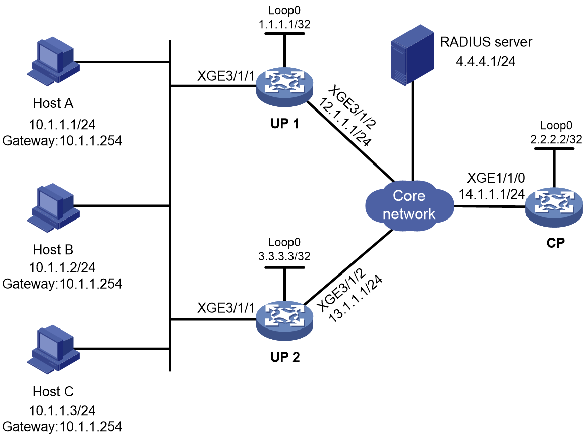
Prerequisites
Configure IP addresses for interfaces, and make sure devices can reach each other at Layer 3. (Details not shown.)
Set up the management channel, control channel, and protocol channel between the CP and UP. (Details not shown.)
Procedure
1. Configure the RADIUS server:
# Add BRAS IP address 12.1.1.1 and secret radius to the clients.conf file.
client 12.1.1.1/32 {
ipaddr = 12.1.1.1
netmask=32
secret=radius
}
# Add the usernames and passwords to the users user information file. The usernames are the host IP addresses 10.1.1.1, 10.1.1.2, and 10.1.1.3 and the passwords are all radius.
10.1.1.1 Cleartext-Password :="radius"
10.1.1.2 Cleartext-Password :="radius"
10.1.1.3 Cleartext-Password :="radius"
2. Configure UP 1 to operate in user plane mode.
<UP1> system-view
[UP1] work-mode user-plane
3. Configure UP 2 in the same way UP 1 is configured. (Details not shown.)
4. Configure the CP:
a. Configure a UP backup group
# Create UP backup group g1, and assign UP 1024 and UP 1025 to the group.
[CP] up-backup-group g1
[CP-up-backup-group-g1] backup up-id 1024
This operation might lead to migration and cause the number of UP devices to exceed the upper limit. Continue? [Y/N]y
[CP-up-backup-group-g1] backup up-id 1025
This operation might lead to migration and cause the number of UP devices to exceed the upper limit. Continue? [Y/N]y
[CP-up-backup-group-g1] quit
# Create UP backup profile 1, configure the backup mode as hot-standby backup mode, and configure UP 1024 acts as the master UP and UP 1025 acts as the backup UP.
[CP] up-backup-profile 1 hot-standby
[CP-up-backup-profile-1] backup-group master remote-xge 1024/3/1/1 backup remote-xge 1025/3/1/1 vrid 1 resource-id 1
[CP-up-backup-profile-1] quit
b. Configure the DHCP server:
# Configure a local BAS IP address pool pool1, bind it to UP backup profile 1, and specify the gateway address as 10.1.1.254 for static users.
[CP] ip pool pool1 bas local
[CP-ip-pool-pool1] binding up-backup-profile 1
[CP-ip-pool-pool1] gateway 10.1.1.254 mask 255.255.255.0
[CP-ip-pool-pool1] forbidden-ip 10.1.1.254
[CP-ip-pool-pool1] quit
# Enable the DHCP server to return a DHCP-NAK message if the client notions of their IP addresses are incorrect.
[CP] dhcp server request-ip-address check
c. Configure a RADIUS scheme:
# Create RADIUS scheme rs1, and enter its view.
[CP] radius scheme rs1
# Configure primary servers and keys for authentication and accounting.
[CP-radius-rs1] primary authentication 4.4.4.1
[CP-radius-rs1] primary accounting 4.4.4.1
[CP-radius-rs1] key authentication simple radius
[CP-radius-rs1] key accounting simple radius
# Exclude the ISP name from the username sent to the RADIUS server.
[CP-radius-rs1] user-name-format without-domain
[CP-radius-rs1] quit
d. Configure ISP domain dm1 to use local AAA.
[CP] domain name dm1
[CP-isp-dm1] authentication ipoe local
[CP-isp-dm1] accounting ipoe local
[CP-isp-dm1] authorization ipoe local
[CP-isp-dm1] authorization-attribute ip-pool pool1
[CP-isp-dm1] quit
e. Configure IPoE:
# Create a global static user, and specify the interfaces that user uses for UP backup.
[CP] ip subscriber session static ip 10.1.1.1 10.1.1.3 domain dm1 interface remote-xge 1024/3/1/1 up-backup-interface remote-xge 1025/3/1/1
# Enter the view of remote interfaces Remote-XGE1024/3/1/1 and Remote-XGE1025/3/1/1.
[CP] interface range remote-xge 1024/3/1/1 remote-xge 1025/3/1/1
# Enable IPoE and configure Layer 3 access mode.
[CP–if-range] ip subscriber routed enable
# Enable unclassified-IP packet initiation.
[CP–if-range] ip subscriber initiator unclassified-ip enable
# Configure plaintext password radius for authentication.
[CP–if-range] ip subscriber password plaintext radius
[CP–if-range] quit
Verifying the configuration
# After Host A comes online, display the online IPoE user information on the CP.
[CP] display access-user auth-type bind
Slot 97:
UserID Interface IP address MAC address S-/C-VLAN
Username IPv6 address Access type
0x50 R-XGE1024/3/1/2 10.1.1.1 84eb-4fcb-0306 -/-
10.1.1.1 - L3 IPoE static
The output above shows that Host A has come online through master UP 1024.
# On master UP 1024, execute the shutdown to shut down interface Ten-GigabitEthernet 3/1/1. Then, display the online IPoE user information on the CP.
[CP] display access-user auth-type bind
Slot 97:
UserID Interface IP address MAC address S-/C-VLAN
Username IPv6 address Access type
0x50 R-XGE1024/3/1/2 10.1.1.1 84eb-4fcb-0306 -/-
10.1.1.1 - L3 IPoE static
The output above shows that Host A has automatically switched to UP 1024 for UP backup.
Example: Configuring unclassified-IP packet initiation (VSI interface)
Network configuration
As shown in Figure 252:
· The host is assigned an IP address manually or through DHCP, and accesses the BRAS in IPoE mode through a Layer 3 network.
· Use the RADIUS server as the authentication, authorization, and accounting server. This section uses the Linux Free RADIUS server as an example.
· The BRAS supports CUPS for IPoE. Users are connected to UPs. The CP acts as the IPoE controller module.
· Users access the UP through a VXLAN tunnel.
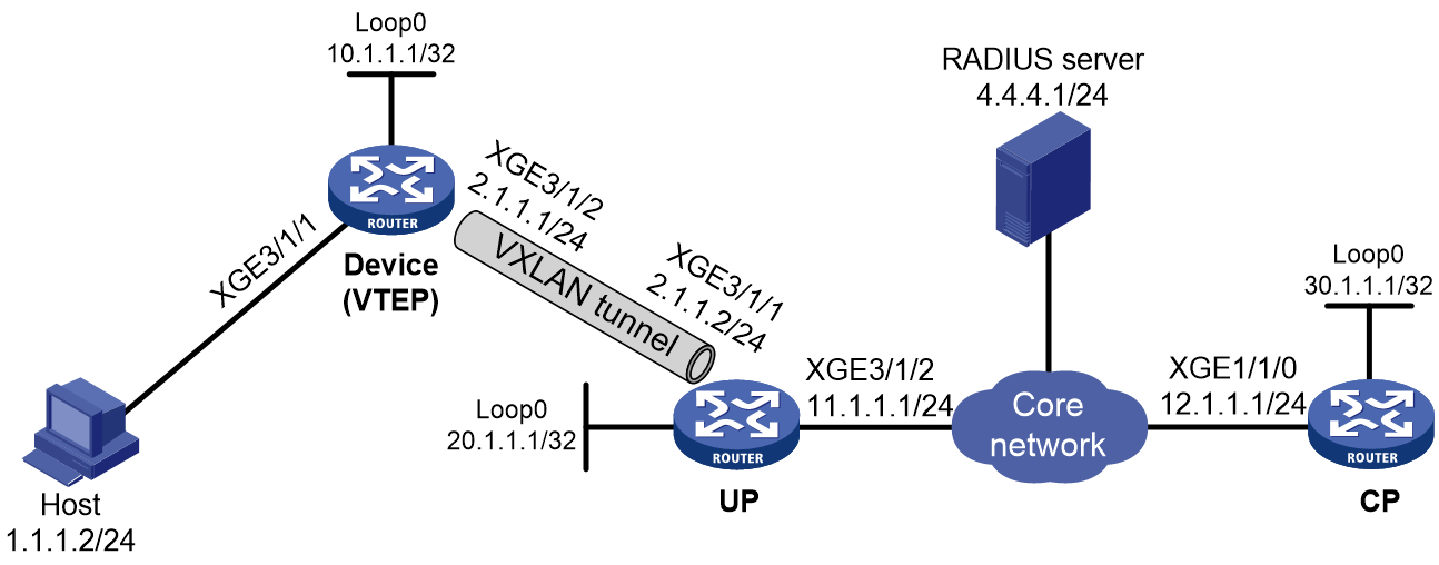
Prerequisites
Configure IP addresses for interfaces, and make sure devices can reach each other at Layer 3. (Details not shown.)
Set up the management channel, control channel, and protocol channel between the CP and UP. (Details not shown.)
Procedure
1. Configure the RADIUS server:
# Add BRAS IP address 12.1.1.1 and secret radius to the clients.conf file.
client 12.1.1.1/32 {
ipaddr = 12.1.1.1
netmask=32
secret=radius
}
# Add the username and password to the users user information file. The username is the host IP address 1.1.1.2 and the password is radius.
1.1.1.2 Cleartext-Password :="radius"
2. Configure the VTEP:
# Enable L2VPN.
[VTEP] l2vpn enable
# Create VSI instance vpna and VXLAN 10.
[VTEP] vsi vpna
[VTEP-vsi-vpna] vxlan 10
[VTEP-vsi-vpna-vxlan-10] quit
[VTEP-vsi-vpna] quit
# Configure a VXLAN tunnel between the VTEP and UP: create tunnel interface Tunnel1 in VXLAN mode, specify the source address of the tunnel as 10.1.1.1 (IP address of Loopback 0 on the VTEP), and specify the destination address of the tunnel as 20.1.1.1 (IP address of interface Loopback 0 on the UP).
[VTEP] interface tunnel 1 mode vxlan
[VTEP-Tunnel1] source 10.1.1.1
[VTEP-Tunnel1] destination 20.1.1.1
[VTEP-Tunnel1] quit
# Associate interface Tunnel1 with VXLAN 10.
[VTEP] vsi vpna
[VTEP-vsi-vpna] vxlan 10
[VTEP-vsi-vpna-vxlan-10] tunnel 1
[VTEP-vsi-vpna-vxlan-10] quit
# Map the user access interface Ten-GigabitEthernet3/1/1 to VSI instance vpna.
[VTEP] interface ten-gigabitethernet 3/1/1
[VTEP-Ten-GigabitEthernet3/1/1] xconnect vsi vpna
[VTEP-Ten-GigabitEthernet3/1/1] quit
3. Configure the UP:
# Enable L2VPN.
[UP] l2vpn enable
# Create VSI instance vpna and VXLAN 10.
[UP] vsi vpna
[UP-vsi-vpna] vxlan 10
[UP-vsi-vpna-vxlan-10] quit
[UP-vsi-vpna] quit
# Configure a VXLAN tunnel between the UP and VTEP: create tunnel interface Tunnel1 in VXLAN mode, specify the source address of the tunnel as 20.1.1.1 (IP address of Loopback 0 on the UP), and specify the destination address of the tunnel as 10.1.1.1 (IP address of interface Loopback 0 on the VTEP).
[UP] interface tunnel 1 mode vxlan
[UP-Tunnel1] source 20.1.1.1
[UP-Tunnel1] destination 10.1.1.1
[UP-Tunnel1] quit
# Associate interface Tunnel1 with VXLAN 10.
[UP] vsi vpna
[UP-vsi-vpna] vxlan 10
[UP-vsi-vpna-vxlan-10] tunnel 1
[UP-vsi-vpna-vxlan-10] quit
[UP-vsi-vpna] quit
# Create VSI-interface 1, and assign an IP address to it. The IP address will be used as the gateway IP address for VMs in VXLAN 10. Specify the VSI interface as a distribute gateway.
[UP] interface vsi-interface 1
[UP-Vsi-interface1] ip address 1.1.1.1 255.255.255.0
[UP-Vsi-interface1] distributed-gateway local
# Configure a MAC address for VSI interface 1 on the UP.
[UP–Vsi-interface1] mac-address 9070-091f-0200
[UP-Vsi-interface1] quit
# Specify VSI interface 1 as the gateway interface for VSI vpna.
[UP] vsi vpna
[UP-vsi-vpna] gateway vsi-interface 1
[UP-vsi-vpna] quit
4. Configure the device to operate in user plane mode.
[UP] work-mode user-plane
5. Configure the CP:
a. Configure the DHCP server:
# Create IPv4 address pool pool1 and enter its view.
[CP] ip pool pool1 bas local
# Specify subnet 1.1.1.1/24 for dynamic allocation in the address pool.
[CP-ip-pool-pool1] gateway 1.1.1.1 mask 255.255.255.0
[CP-ip-pool-pool1] forbidden-ip 1.1.1.1
# Bind the IP address pool to UP 1024.
[CP-ip-pool-pool1] binding up-id 1024
[CP-ip-pool-pool1] quit
b. Configure a RADIUS scheme:
# Create RADIUS scheme rs1, and enter its view.
[CP] radius scheme rs1
# Configure primary servers and keys for authentication and accounting.
[CP-radius-rs1] primary authentication 4.4.4.1
[CP-radius-rs1] primary accounting 4.4.4.1
[CP-radius-rs1] key authentication simple radius
[CP-radius-rs1] key accounting simple radius
# Exclude the ISP name from the username sent to the RADIUS server.
[CP-radius-rs1] user-name-format without-domain
[CP-radius-rs1] quit
c. Configure ISP domains:
# Create ISP domain dm1, and enter its view.
[CP] domain name dm1
# Configure the ISP domain to use RADIUS scheme rs1 for authentication, authorization, and accounting and authorize address pool pool1.
[CP-isp-dm1] authentication ipoe radius-scheme rs1
[CP-isp-dm1] authorization ipoe radius-scheme rs1
[CP-isp-dm1] accounting ipoe radius-scheme rs1
[CP-isp-dm1] authorization-attribute ip-pool pool1
[CP-isp-dm1] quit
d. Configure IPoE:
# Enter the view of remote interface Remote-VSI 1024/1.
[CP] interface remote-vsi 1024/1
# Enable IPoE and configure Layer 2 access mode.
[CP–Remote-Vsi1024/1] ip subscriber l2-connected enable
# Enable unclassified-IP packet initiation.
[CP–if-range] ip subscriber initiator unclassified-ip enable
# Configure ISP domain isp1 for IPv4 unclassified-IP users.
[CP–Remote-Vsi1024/1] ip subscriber unclassified-ip domain dm1
# Configure plaintext password radius for authentication.
[CP–Remote-Vsi1024/1] ip subscriber password plaintext radius
[CP–Remote-Vsi1024/1] quit
Verifying the configuration
# Display the online IPoE user information on the CP.
[CP] display access-user interface remote-vsi 1024/1
Slot 97:
UserID Interface IP address MAC address S-/C-VLAN
Username IPv6 address Access type
0x80100095 R-Vsi1024/1 1.1.1.2 0020-9400-0002 -/-
1.1.1.2 - L2 IPoE static
Configuring portal authentication
Restrictions and guidelines: Portal configuration
The device does not support users to access the network through portal authentication. The portal features can only be used in IPoE Web authentication scenarios.
Portal authentication tasks at a glance
To configure portal authentication, perform the following tasks:
1. Configuring a remote portal authentication server
Perform this task if a remote portal server is used.
2. Configuring local portal service features
Perform this task if the access device acts as a portal authentication server.
3. (Optional.) Configuring portal detection features
¡ Configuring portal authentication server detection
¡ Configuring portal user synchronization
4. (Optional.) Configuring attributes for portal packets and RADIUS packets
¡ Configuring portal packet attributes
This task includes configuring the BAS-IP or BAS-IPv6 attribute for portal notifications packets.
You must configure the BAS-IP or BAS-IPv6 attribute if the device IP address specified on the portal authentication server is not the IP address of the output interface for portal notification packets.
¡ Excluding an attribute from portal protocol packets
5. (Optional.) Configuring MAC-based quick portal authentication
a. Configuring a MAC binding server
b. Specifying a MAC binding server on an interface
6. Obtaining user access information from ARP or ND entries
On an IPoE Web authentication network, this task is required when DHCP access users and the portal authentication server belong to different VPNs.
Configuring a remote portal authentication server
About this task
The device searches for a portal authentication server for a received portal request packet according to the source IP address and VPN information of the packet.
· If a matching portal authentication server is found, the device regards the packet valid and sends an authentication response packet to the portal authentication server. After a user logs in to the device, the user interacts with the portal authentication server as needed.
· If no matching portal authentication server is found, the device drops the packet.
Restrictions and guidelines
Do not delete a portal authentication server in use. Otherwise, users authenticated by that server cannot log out correctly.
Procedure
1. Enter system view.
system-view
2. Create a portal authentication server and enter its view.
portal server server-name
You can create multiple portal authentication servers.
3. Specify the IP address of the portal authentication server.
ip ipv4-address [ vpn-instance vpn-instance-name] [ key { cipher | simple } string ]
IPv6:
ipv6 ipv6-address [ vpn-instance vpn-instance-name] [ key { cipher | simple } string ]
By default, no portal authentication server is specified.
4. (Optional.) Set the destination UDP port number used by the device to send unsolicited portal packets to the portal authentication server.
port port-number
By default, the UDP port number is 50100.
This port number must be the same as the listening port number specified on the portal authentication server.
In a portal proxy network, make sure this port number is the same as the listening port number specified on the portal proxy.
5. (Optional.) Specify the portal authentication server type.
server-type { cmcc | imc }
By default, the portal authentication server type is IMC.
The specified server type must be the same as the type of the portal authentication server actually used.
6. (Optional.) Set the maximum number of times and the interval for retransmitting a logout notification packet.
logout-notify retry retries interval interval
By default, the device does not retransmit a logout notification packet.
7. (Optional.) Configure the device to periodically register with the portal authentication server.
server-register [ interval interval-value ]
By default, the device does not register with a portal authentication server.
Configuring local portal service features
About the local portal service
After a local portal service is configured, the device acts as the portal Web server and portal authentication server to perform portal authentication on users. The portal authentication page file is saved in the root directory of the device.
Restrictions and guidelines for configuring local portal service features
For an interface to use the local portal service, the URL of the portal Web server specified for the interface must meet the following requirements:
· The IP address in the URL must be the IP address of a Layer 3 interface (except 127.0.0.1) on the device, and the IP address must be reachable to portal clients.
· The URL must be ended with /portal/. For example: http://1.1.1.1/portal/.
You must customize the authentication pages and upload them to the device.
Customizing authentication pages
About this task
Authentication pages are HTML files. Local portal authentication requires the following authentication pages:
· Logon page
· Logon success page
· Logon failure page
· Online page
· System busy page
· Logoff success page
You must customize the authentication pages, including the page elements that the authentication pages will use, for example, back.jpg for authentication page Logon.htm.
Follow the authentication page customization rules when you edit the authentication page files.
File name rules
The names of the main authentication page files are fixed (see Table 2). You can define the names of the files other than the main authentication page files. File names and directory names are case insensitive.
Table 2 Main authentication page file names
|
Main authentication page |
File name |
|
Logon page |
logon.htm |
|
Logon success page |
logonSuccess.htm |
|
Logon failure page |
logonFail.htm |
|
Online page Pushed after the user gets online for online notification |
online.htm |
|
System busy page Pushed when the system is busy or the user is in the logon process |
busy.htm |
|
Logoff success page |
logoffSuccess.htm |
Page request rules
The local portal Web service supports only Get and Post requests.
· Get requests—Used to get the static files in the authentication pages and allow no recursion. For example, if file Logon.htm includes contents that perform Get action on file ca.htm, file ca.htm cannot include any reference to file Logon.htm.
· Post requests—Used when users submit username and password pairs, log in, and log out.
Post request attribute rules
1. Observe the following requirements when editing a form of an authentication page:
¡ An authentication page can have multiple forms, but there must be one and only one form whose action is logon.cgi. Otherwise, user information cannot be sent to the access device.
¡ The username attribute is fixed as PtUser. The password attribute is fixed as PtPwd.
¡ The value of the PtButton attribute is either Logon or Logoff, which indicates the action that the user requests.
¡ A logon Post request must contain PtUser, PtPwd, and PtButton attributes.
¡ A logoff Post request must contain the PtButton attribute.
2. Authentication pages logon.htm and logonFail.htm must contain the logon Post request.
The following example shows part of the script in page logon.htm.
<form action=logon.cgi method = post >
<p>User name:<input type="text" name = "PtUser" style="width:160px;height:22px" maxlength=64>
<p>Password :<input type="password" name = "PtPwd" style="width:160px;height:22px" maxlength=32>
<p><input type=SUBMIT value="Logon" name = "PtButton" style="width:60px;" onclick="form.action=form.action+location.search;">
</form>
3. Authentication pages logonSuccess.htm and online.htm must contain the logoff Post request.
The following example shows part of the script in page online.htm.
<form action=logon.cgi method = post >
<p><input type=SUBMIT value="Logoff" name="PtButton" style="width:60px;">
</form>
Page file compression and saving rules
You must compress the authentication pages and their page elements into a standard zip file.
· The name of a zip file can contain only letters, numbers, and underscores.
· The authentication pages must be placed in the root directory of the zip file.
· Zip files can be transferred to the device through FTP or TFTP and must be saved in the root directory of the device.
Examples of zip files on the device:
<Sysname> dir
Directory of flash:
1 -rw- 1405 Feb 28 2008 15:53:20 ssid1.zip
0 -rw- 1405 Feb 28 2008 15:53:31 ssid2.zip
2 -rw- 1405 Feb 28 2008 15:53:39 ssid3.zip
3 -rw- 1405 Feb 28 2008 15:53:44 ssid4.zip
2540 KB total (1319 KB free)
Redirecting authenticated users to a specific webpage
To make the device automatically redirect authenticated users to a specific webpage, do the following in logon.htm and logonSuccess.htm:
1. In logon.htm, set the target attribute of Form to _blank.
See the contents in gray:
<form method=post action=logon.cgi target="_blank">
2. Add the function for page loading pt_init() to logonSuccess.htm.
See the contents in gray:
<html>
<head>
<title>LogonSuccess</title>
<script type="text/javascript" language="javascript" src="pt_private.js"></script>
</head>
<body onload="pt_init();" onbeforeunload="return pt_unload();">
... ...
</body>
</html>
Configuring a local portal Web service
Prerequisites
Before you configure an HTTPS-based local portal Web service, you must complete the following tasks:
· Configure a PKI policy, obtain the CA certificate, and request a local certificate. For more information, see "Configuring PKI."
· Configure an SSL server policy, and specify the PKI domain configured in the PKI policy.
During SSL connection establishment, the user browser might display a message that it cannot verify server identity by certificate. For users to perform portal authentication without checking such a message, configure an SSL server policy to request a client-trusted certificate on the device. The name of the policy must be https_redirect. For more information about SSL server policy configuration, see "Configuring SSL."
Procedure
1. Enter system view.
system-view
2. Create an HTTP- or HTTPS-based local portal Web service and enter its view.
portal local-web-server { http | https ssl-server-policy policy-name [ tcp-port port-number ] }
3. Specify the default authentication page file for the local portal Web service.
default-logon-page filename
By default, no default authentication page file is specified for the local portal Web service.
To provide local portal Web service for users, you must use this command to specify a customized authentication page file as the default authentication page file.
4. (Optional.) Configure the listening TCP port for the local portal Web service.
tcp-port port-number
By default, the HTTP service listening port number is 80 and the HTTPS service listening port number is the TCP port number set by the portal local-web-server command..
5. (Optional.) Bind the endpoint name to an authentication page file.
logon-page bind device-name device-name file file-name
By default, no endpoint name is bound to an authentication page file.
Configuring portal detection features
Configuring portal authentication server detection
About this task
During portal authentication, if the communication between the access device and portal authentication server is broken, new portal users are not able to log in. Online portal users are not able to log out normally.
To address this problem, the access device needs to be able to detect the reachability changes of the portal server quickly and take corresponding actions to deal with the changes.
The portal authentication server detection feature enables the device to periodically detect portal packets sent by a portal authentication server to determine the reachability of the server. If the device receives a portal packet within a detection timeout (timeout timeout) and the portal packet is valid, the device considers the portal authentication server to be reachable. Otherwise, the device considers the portal authentication server to be unreachable.
Portal packets include user login packets, user logout packets, and heartbeat packets. Heartbeat packets are periodically sent by a server. By detecting heartbeat packets, the device can detect the server's actual status more quickly than by detecting other portal packets.
Restrictions and guidelines
Only the IMC portal authentication server supports sending heartbeat packets. To test server reachability by detecting heartbeat packets, you must enable the server heartbeat feature on the IMC portal authentication server.
You can configure the device to take one or two of the following actions when the server reachability status changes:
· Sending a trap message to the NMS. The trap message contains the name and current state of the portal authentication server.
· Sending a log message, which contains the name, the current state, and the original state of the portal authentication server.
Make sure the detection timeout configured on the device is greater than the server heartbeat interval configured on the portal authentication server.
Procedure
1. Enter system view.
system-view
2. Enter portal authentication server view.
portal server server-name
3. Configure portal authentication server detection.
server-detect [ timeout timeout ] { log | trap } *
By default, portal authentication server detection is disabled.
Configuring portal user synchronization
About this task
Once the access device loses communication with a portal authentication server, the portal user information on the access device and that on the portal authentication server might be inconsistent after the communication resumes. To address this problem, the device provides the portal user synchronization feature. This feature is implemented by sending and detecting portal synchronization packets, as follows:
1. The portal authentication server sends the online user information to the access device in a synchronization packet at the user heartbeat interval.
The user heartbeat interval is set on the portal authentication server.
2. Upon receiving the synchronization packet, the access device compares the users carried in the packet with its own user list and performs the following operations:
¡ If a user contained in the packet does not exist on the access device, the access device informs the portal authentication server to delete the user. The access device starts the synchronization detection timer (timeout timeout) immediately when a user logs in.
¡ If the user does not appear in any synchronization packet within a synchronization detection interval, the access device considers the user does not exist on the portal authentication server and logs the user out.
Restrictions and guidelines
Portal user synchronization requires a portal authentication server to support the portal user heartbeat function. Only the IMC portal authentication server supports the portal user heartbeat function. To implement the portal user synchronization feature, you also need to configure the user heartbeat function on the portal authentication server. Make sure the user heartbeat interval configured on the portal authentication server is not greater than the synchronization detection timeout configured on the access device.
Deleting a portal authentication server on the access device also deletes the user synchronization configuration for the portal authentication server.
Procedure
1. Enter system view.
system-view
2. Enter portal authentication server view.
portal server server-name
3. Configure portal user synchronization.
user-sync timeout timeout
By default, portal user synchronization is disabled.
Configuring portal packet attributes
Configuring the BAS-IP or BAS-IPv6 attribute
About this task
To avoid portal user offline failure and re-DHCP portal authentication failure, the BAS-IP or BAS-IPv6 attribute must be the same as the device IP address on the portal authentication server. Perform this task to configure the BAS-IP or BAS-IPv6 attribute as the device IP address specified on the portal authentication server. The device uses the BAS-IP or BAS-IPv6 attribute value as the source IP address of portal notification packets sent to the portal authentication server.
Restrictions and guidelines
This configuration takes effect only on unsolicited portal notification packets sent to the portal authentication server. For IPv4 portal reply packets, the BAS-IP attribute value is the source IPv4 address of the packets. For IPv6 portal reply packets, the BAS-IPv6 attribute value is the source IPv6 address of the packets.
The global BAS-IP or BAS-IPv6 configuration made in system view takes effect on all interfaces. For an interface, the interface-specific BAS-IP or BAS-IPv6 configuration takes precedence over the global configuration..
Configure the BAS-IP or BAS-IPv6 attribute globally
1. Enter system view.
system-view
2. Configure the BAS-IP or BAS-IPv6 attribute.
IPv4:
portal bas-ip ipv4-address
By default, the BAS-IP attribute value of an IPv4 portal notification packet is the IPv4 address of the packet's output interface.
IPv6:
portal bas-ipv6 ipv6-address
By default, the BAS-IPv6 attribute value of an IPv6 portal notification packet is the IPv6 address of the packet's output interface.
Configuring the BAS-IP or BAS-IPv6 attribute on an interface
1. Enter system view.
system-view
2. Enter Layer 3 interface view.
interface interface-type interface-number
3. Configure the BAS-IP or BAS-IPv6 attribute.
IPv4:
portal bas-ip ipv4-address
For an IPv4 portal reply packet, the default BAS-IP attribute value is the source IPv4 address of the packet. For an IPv4 portal notification packet, the default BAS-IP attribute value is the IPv4 address of the packet's output interface.
IPv6:
portal bas-ipv6 ipv6-address
For an IPv6 portal reply packet, the default BAS-IPv6 attribute value is the source IPv6 address of the packet. For an IPv6 portal notification packet, the default BAS-IPv6 attribute value is the IPv6 address of the packet's output interface.
Excluding an attribute from portal protocol packets
About this task
Support of the portal authentication server for portal protocol attributes varies by the server type. If the device sends the portal authentication server a packet that contains an attribute unsupported by the server, the device and the server cannot communicate.
To address this issue, you can configure portal protocol packets to not carry the attributes unsupported by the portal authentication server.
Procedure
1. Enter system view.
system-view
2. Enter portal authentication server view.
portal server server-name
3. Exclude an attribute from portal protocol packets.
exclude-attribute number [ ack-auth | ack-challenge | ack-info | ack-logout | ack-ntf-user-heartbeat | ntf-challenge | ntf-logout | ntf-useripchange | ntf-user-notify ]
By default, no attributes are excluded from portal protocol packets.
Configuring MAC-based quick portal authentication
Restrictions and guidelines for configuring MAC-based quick portal authentication
Only IPv4 direct authentication supports MAC-based quick portal authentication.
In a network where a portal proxy is deployed, the access device and the MAC binding server communicate with each other through the portal proxy. On the access device, you must configure the portal proxy for the MAC binding server for MAC-based quick portal authentication to take effect.
Configuring a MAC binding server
About this task
You can configure multiple MAC binding servers on the device.
Perform this task to configure MAC binding server parameters, such as the server's IP address, port number, VPN instance, and the pre-shared key for communication between the access device and the server.
Procedure
1. Enter system view.
system-view
2. Create a MAC binding server and enter its view.
portal mac-trigger-server server-name
By default, no MAC binder servers exist.
3. Configure a MAC binding server.
¡ Specify the IP address of the MAC binding server.
ip ipv4-address [ vpn-instance vpn-instance-name ] [ key { cipher | simple } string ]
By default, no IP address is specified for a MAC binding server.
¡ (Optional.) Set the UDP port number on which the MAC binding server listens for MAC binding query packets.
port port-number
By default, the MAC binding server listens for MAC binding query packets on UDP port 50100.
In a portal proxy network, make sure this port number is the same as the listening port number specified on the portal proxy.
¡ (Optional.) Set the maximum number of attempts and the interval for sending MAC binding queries to the MAC binding server.
binding-retry { retries | interval interval } *
By default, the maximum number of query attempts is 3 and the query interval is 1 second.
¡ (Optional.) Specify the type of the MAC binding server.
server-type { cmcc | imc }
By default, the type of a MAC binding server is IMC.
4. (Optional.) Set the free-traffic threshold.
free-traffic threshold value
By default, the free-traffic threshold is 0 bytes.
5. (Optional.) Set the NAS-Port-Type attribute value carried in RADIUS requests sent to the RADIUS server.
nas-port-type value
By default, the NAS-Port-Type attribute value carried in RADIUS requests is not set.
6. (Optional.) Specify the version of the portal protocol.
version version-number
By default, the version of the portal protocol is 1.
7. (Optional.) Set the timeout the device waits for portal authentication to complete after receiving the MAC binding query response.
authentication-timeout minutes
By default, the portal authentication timeout time is 3 minutes.
8. (Optional.) Set the aging time for MAC-trigger entries.
aging-time seconds
By default, the aging time for MAC-trigger entries is 300 seconds.
Specifying a MAC binding server on an interface
About this task
After a MAC binding server is specified on an interface, the device can implement MAC-based quick portal authentication for portal users on the interface.
Procedure
1. Enter system view.
system-view
2. Enter Layer 3 interface view.
interface interface-type interface-number
3. Specify a MAC binding server on the interface.
portal apply mac-trigger-server server-name
By default, no MAC binding server is specified on an interface.
Obtaining user access information from ARP or ND entries
About this task
In an IPoE Web authentication network, when the device receives portal packets from the portal authentication server, it obtains user access information to complete authentication for users.
By default, the device obtains the user access information from FIB entries in the VPN instance of the portal authentication server. In the following situation, however, the device cannot get user access information from FIB and therefore users cannot pass Web authentication:
· The DHCP access users and the portal authentication server belong to different VPN instances.
· The user access interface is not bound to a VPN instance.
To resolve this issue, you can perform this task on the device. When this feature is enabled, the device first attempts to obtain user access information from ARP or ND entries during Web authentication. If the attempt fails, the device obtains user access information from UCM user entries.
Restrictions and guidelines
As a best practice, configure this feature in all IPoE Web authentication scenarios.
To use this feature, make sure the VPN instances do not have overlapping IP addresses. Otherwise, this feature cannot ensure normal user logins.
Procedure
1. Enter system view.
system-view
2. Configure the device to obtain user information from ARP or ND entries.
portal access-info trust { arp | nd }
By default, the device obtains user information from FIB entries.
Display and maintenance commands for portal
Execute display commands in any view and the reset command in user view.
|
Task |
Command |
|
Display statistics for messages exchanged between portal and IPoE. |
display portal ip-subscriber message statistics |
|
Display MAC-trigger entries for portal users. |
display portal mac-trigger entry [ ip ipv4-address ] |
|
Display information about MAC binding servers. |
display portal mac-trigger-server { all | name server-name } |
|
Display statistics for messages exchanged between the device and MAC binding servers |
display portal mac-trigger-server packet statistics |
|
Display packet statistics for portal authentication servers. |
display portal packet statistics [ server server-name ] |
|
Display portal authentication server information. |
display portal server [ server-name ] |
|
Display session information for portal users or portal-based IPoE authentication users. |
display portal session user-type { ipoe | portal } |
|
Clear statistics for messages exchanged between portal and IPoE. |
reset portal ip-subscriber message statistics |
|
Clear statistics for messages exchanged between the device and MAC binding servers. |
reset portal mac-trigger-server packet statistics |
|
Clear packet statistics for portal authentication servers. |
reset portal packet statistics [ server server-name ] |
