- Table of Contents
- Related Documents
-
| Title | Size | Download |
|---|---|---|
| 01-ACL configuration | 165.11 KB |
Contents
Restrictions and guidelines: ACL configuration
Configuring an IPv4 advanced ACL
Configuring an IPv6 advanced ACL
Configuring a static ACL whitelist
Configuring packet filtering with ACLs
About packet filtering with ACLs
Applying an ACL to filter packets globally
Applying an ACL to an interface for packet filtering
Configuring logging and SNMP notifications for packet filtering
Setting the packet filtering default action
Enabling hardware-count for the packet filtering default action
Display and maintenance commands for ACL
Example: configuring interface-based packet filter
Configuring ACLs
About ACLs
An access control list (ACL) is a set of rules for identifying traffic based on criteria such as source IP address, destination IP address, and port number. The rules are also called permit or deny statements.
ACLs are primarily used for packet filtering. You can also use ACLs in QoS, security, routing, and other modules for identifying traffic. The packet drop or forwarding decisions depend on the modules that use ACLs.
Numbering and naming ACLs
When creating an ACL, you must assign it a number or name for identification. You can specify an existing ACL by its number or name. Each ACL type has a unique range of ACL numbers.
For basic or advanced ACLs with the same number, you must use the ipv6 keyword to distinguish them. For ACLs with the same name, you must use the ipv6 and mac keywords to distinguish them.
ACL types
|
Type |
ACL number |
IP version |
Match criteria |
|
Basic ACLs |
2000 to 2999 |
IPv4 |
Source IPv4 address. |
|
IPv6 |
Source IPv6 address. |
||
|
Advanced ACLs |
3000 to 3999 |
IPv4 |
Source IPv4 address, destination IPv4 address, packet priority, protocol number, and other Layer 3 and Layer 4 header fields. |
|
IPv6 |
Source IPv6 address, destination IPv6 address, packet priority, protocol number, and other Layer 3 and Layer 4 header fields. |
||
|
Layer 2 ACLs |
4000 to 4999 |
IPv4 and IPv6 |
Layer 2 header fields, such as source and destination MAC addresses, 802.1p priority, and link layer protocol type. |
ACL match order on cards
ACL match order
The match order of ACLs is as follows:
· Global packet filtering.
· Packet filtering configured on an aggregate interface.
· Packet filtering configured on a physical interface or MP-group interface.
· Packet filtering configured on a VLAN interface.
· QoS policy applied to a control plane.
· QoS policy applied to a user profile.
· QoS policy applied globally with a priority of 1.
· QoS policy applied to an aggregate interface with a priority of 1.
· QoS policy applied to an interface with a priority of 1.
· Policy-based routing (PBR) configured on an aggregate interface.
· PBR configured on a Layer 3 physical interface.
· PBR configured on a VLAN interface.
· QoS policy applied globally with no priority specified.
· QoS policy applied to an aggregate interface with no priority specified.
· QoS policy applied to an interface with no priority specified.
· QoS policy applied to a VLAN.
Second ACL matching
A second matching occurs on incoming packets when a packet filter, an interface or global QoS policy with a priority of 1, or a user profile QoS policy is applied. Incoming packets are first compared against the ACL used by the packet filter, interface or global QoS policy, or the user profile QoS policy. Permitted packets are further compared against the ACL of a lower priority.
A second matching also applies to the outbound direction only on CSPEX-1802X, CSPEX-1802XA, CSPEX-1812X-E, CSPEX-2304X-G, CEPC-CQ8L, CEPC-CQ8LA, CEPC-CQ16L1, CSPEX-1502XA, RX-SPE200-E.
ACL rule match order
The rules in an ACL are sorted in a specific order. When a packet matches a rule, the device stops the match process and performs the action defined in the rule. If an ACL contains overlapping or conflicting rules, the matching result and action to take depend on the rule order.
The following ACL match orders are available:
· config—Sorts ACL rules in ascending order of rule ID. A rule with a lower ID is matched before a rule with a higher ID. If you use this method, check the rules and their order carefully.
· auto—Sorts ACL rules in depth-first order. Depth-first ordering makes sure any subset of a rule is always matched before the rule. Table 1 lists the sequence of tie breakers that depth-first ordering uses to sort rules for each type of ACL.
Table 1 Sort ACL rules in depth-first order
|
ACL type |
Sequence of tie breakers |
|
IPv4 basic ACL |
1. VPN instance. 2. More 0s in the source IPv4 address wildcard (more 0s means a narrower IPv4 address range). 3. Rule configured earlier. |
|
IPv4 advanced ACL |
1. VPN instance. 2. Specific protocol number. 3. More 0s in the source IPv4 address wildcard mask. 4. More 0s in the destination IPv4 address wildcard. 5. Narrower TCP/UDP service port number range. 6. Rule configured earlier. |
|
IPv6 basic ACL |
1. VPN instance. 2. Longer prefix for the source IPv6 address (a longer prefix means a narrower IPv6 address range). 3. Rule configured earlier. |
|
IPv6 advanced ACL |
1. VPN instance. 2. Specific protocol number. 3. Longer prefix for the source IPv6 address. 4. Longer prefix for the destination IPv6 address. 5. Narrower TCP/UDP service port number range. 6. Rule configured earlier. |
|
Layer 2 ACL |
1. More 1s in the source MAC address mask (more 1s means a smaller MAC address). 2. More 1s in the destination MAC address mask. 3. Rule configured earlier. |
A wildcard mask, also called an inverse mask, is a 32-bit binary number represented in dotted decimal notation. In contrast to a network mask, the 0 bits in a wildcard mask represent "do care" bits, and the 1 bits represent "don't care" bits. If the "do care" bits in an IP address are identical to the "do care" bits in an IP address criterion, the IP address matches the criterion. All "don't care" bits are ignored. The 0s and 1s in a wildcard mask can be noncontiguous. For example, 0.255.0.255 is a valid wildcard mask.
Rule numbering
ACL rules can be manually numbered or automatically numbered. This section describes how automatic ACL rule numbering works.
Rule numbering step
If you do not assign an ID to the rule you are creating, the system automatically assigns it a rule ID. The rule numbering step sets the increment by which the system automatically numbers rules. For example, the default ACL rule numbering step is 5. If you do not assign IDs to rules you are creating, they are automatically numbered 5, 10, 15, 20, and so on. The wider the numbering step, the more rules you can insert between two rules.
By introducing a gap between rules rather than contiguously numbering rules, you have the flexibility of inserting rules in an ACL. This feature is important for a config-order ACL, where ACL rules are matched in ascending order of rule ID.
Automatic rule numbering and renumbering
The ID automatically assigned to an ACL rule takes the nearest higher multiple of the numbering step to the current highest rule ID, starting with 5.
For example, if the step is 5, and there are five rules numbered 0, 5, 9, 10, and 12, the newly defined rule is numbered 15. If the ACL does not contain a rule, the first rule is numbered 5.
Whenever the step changes, the rules are renumbered, starting from 5. For example, changing the step from 5 to 2 renumbers rules 5, 10, 13, and 15 as rules 5, 7, 9, and 11.
For an ACL of the match order auto, rules are sorted in depth-first order, and are renumbered based on the match order. For example, rules are in the match order of 5, 10, and 15. Changing the numbering step to 2 renumbers rules 5, 15, and 10 (not 5, 10, and 15) as rules 5, 7, 9.
Restrictions and guidelines: ACL configuration
· If you create a named ACL, you can enter the view of the ACL only by using the acl { [ ipv6 ] { advanced | basic } | mac } name acl-name command.
· If you create a numbered ACL, you can enter the view of the ACL only by using the acl { [ ipv6 ] | { advanced | basic } | mac } acl-number command.
ACL tasks at a glance
To configure an ACL, perform the following tasks:
· Configure ACLs according to the characteristics of the packets to be matched
· (Optional.) Copying an ACL
· (Optional.) Configuring TCAM usage alarm
· (Optional.) Configuring a static ACL whitelist
· (Optional.) Configuring packet filtering with ACLs
Configuring a basic ACL
About basic ACLs
Basic ACLs match packets based only on source IP addresses.
Basic ACLs can be used in the following scenarios:
· To improve security when the device acts as an FTP or TFTP server, you can use basic ACLs to allow only matching clients to access the server. For more information, see FTP and TFTP configuration in Fundamentals Configuration Guide.
· In a NAT scenario, you can use basic ACLs to translate the address of only matching packets.
· In a multicast scenario, you can use basic ACLs in a multicast source policy to receive or forward only matching multicast packets. For more information about multicast source policy, see PIM configuration and IPv6 PIM configuration in IP Multicast Configuration Guide.
· To filter routes in a routing policy, you can use basic ACLs to receive or send matching routes. For more information about routing policy, see Layer 3—IP Routing Configuration Guide.
· To take different QoS actions on different traffic types, you can use basic ACLs to classify traffic. For more information about traffic classes, see "Configuring QoS."
Configuring an IPv4 basic ACL
1. Enter system view.
system-view
2. Create an IPv4 basic ACL and enter its view.
acl basic { acl-number | name acl-name } [ match-order { auto | config } ]
3. (Optional.) Configure a description for the IPv4 basic ACL.
description text
By default, an IPv4 basic ACL does not have a description.
4. (Optional.) Set the rule numbering step.
step step-value
By default, the rule numbering step is 5 and the start rule ID is 5.
5. Create or edit a rule.
rule [ rule-id ] { deny | permit } [ counting | fragment | logging | source { object-group address-group-name | source-address source-wildcard | any } | time-range time-range-name | vpn-instance vpn-instance-name ] *
The logging keyword takes effect only when the module (for example, packet filtering) that uses the ACL supports logging.
The logging keyword does not take effect if it is used in a QoS traffic class.
6. (Optional.) Add or edit a rule comment.
rule rule-id comment text
By default, no rule comment is configured.
Configuring an IPv6 basic ACL
1. Enter system view.
system-view
2. Create an IPv6 basic ACL view and enter its view.
acl ipv6 basic { acl-number | name acl-name } [ match-order { auto | config } ]
3. (Optional.) Configure a description for the IPv6 basic ACL.
description text
By default, an IPv6 basic ACL does not have a description.
4. (Optional.) Set the rule numbering step.
step step-value
By default, the rule numbering step is 5 and the start rule ID is 5.
5. Create or edit a rule.
rule [ rule-id ] { deny | permit } [ counting | fragment | logging | routing [ type routing-type ] | source { object-group address-group-name | source-address source-prefix | source-address/source-prefix | any } | time-range time-range-name | vpn-instance vpn-instance-name ] *
The logging keyword takes effect only when the module (for example, packet filtering) that uses the ACL supports logging.
The logging keyword does not take effect if it is used in a QoS traffic class.
6. (Optional.) Add or edit a rule comment.
rule rule-id comment text
By default, no rule comment is configured.
Configuring an advanced ACL
About advanced ACLs
Advanced ACLs can be used in the following scenarios:
· When the device acts as an FTP or TFTP server, you can use advanced ACLs to allow only matching clients to access the server. For more information, see FTP and TFTP configuration in Fundamentals Configuration Guide.
· In a NAT scenario, you can use advanced ACLs to translate the address of only matching packets.
· In a multicast scenario, you can use advanced ACLs in a multicast source policy to receive or forward only matching multicast packets. For more information about multicast source policy, see PIM configuration and IPv6 PIM configuration in IP Multicast Configuration Guide.
· To filter routes in a routing policy, you can use advanced ACLs to receive or send matching routes. For more information about routing policy, see Layer 3—IP Routing Configuration Guide.
· To take different QoS actions on different traffic types, you can use advanced ACLs to classify traffic. For more information about traffic classification see "Configuring QoS."
Advanced ACLs match packets based on the following criteria:
· Source IP addresses.
· Destination IP addresses.
· Packet priorities.
· Local QoS IDs.
· Protocol types.
· Other protocol header information, such as TCP/UDP source and destination port numbers, TCP flags, ICMP message types, and ICMP message codes.
Compared to basic ACLs, advanced ACLs allow more flexible and accurate filtering.
Configuring an IPv4 advanced ACL
1. Enter system view.
system-view
2. Create an IPv4 advanced ACL and enter its view.
acl advanced { acl-number | name acl-name } [ match-order { auto | config } ]
The value range for the acl-number argument is 3000 to 3999
If you create a named IPv4 advanced ACL, you can enter its view by using only the acl advanced name acl-name command.
If you create a numbered IPv4 advanced ACL, you can enter its view by using only the acl advanced acl-number command.
3. (Optional.) Configure a description for the IPv4 advanced ACL.
description text
By default, an IPv4 advanced ACL does not have a description.
4. (Optional.) Set the rule numbering step.
step step-value
By default, the rule numbering step is 5 and the start rule ID is 5.
5. Create or edit a rule.
rule [ rule-id ] { deny | permit } protocol [ { { ack ack-value | fin fin-value | psh psh-value | rst rst-value | syn syn-value | urg urg-value } * | established } | counting | destination { object-group address-group-name | dest-address dest-wildcard | any } | destination-port { object-group port-group-name | operator port1 [ port2 ] } | { dscp dscp1 [ to dscp2 ] | { precedence precedence | tos tos } * } | fragment | icmp-type { icmp-type [ icmp-code ] | icmp-message } | logging | source { object-group address-group-name | source-address source-wildcard | any } | source-port { object-group port-group-name | operator port1 [ port2 ] } | time-range time-range-name | ttl operator ttl-value1 [ ttl-value2 ] | { { user-group group-name | user-group-any } | { { source-user-group source-group-name | source-user-group-any } | { destination-user-group destination-group-name | destination-user-group-any } } * } | vpn-instance vpn-instance-name ] *
The logging keyword takes effect only when the module (for example, packet filtering) that uses the ACL supports logging.
The logging keyword does not take effect if it is used in a QoS traffic class.
6. (Optional.) Add or edit a rule comment.
rule rule-id comment text
By default, no rule comment is configured.
Configuring an IPv6 advanced ACL
1. Enter system view.
system-view
2. Create an IPv6 advanced ACL and enter its view.
acl ipv6 advanced { acl-number | name acl-name } [ match-order { auto | config } ]
The value range for the acl-number argument is 3000 to 3999
If you create a named IPv6 advanced ACL, you can enter its view by using only the acl ipv6 advanced name acl-name command.
If you create a numbered IPv6 advanced ACL, you can enter its view by using only the acl ipv6 advanced acl-number command.
3. (Optional.) Configure a description for the IPv6 advanced ACL.
description text
By default, an IPv6 advanced ACL does not have a description.
4. (Optional.) Set the rule numbering step.
step step-value
By default, the rule numbering step is 5 and the start rule ID is 5.
5. Create or edit a rule.
rule [ rule-id ] { deny | permit } protocol [ { { ack ack-value | fin fin-value | psh psh-value | rst rst-value | syn syn-value | urg urg-value } * | established } | counting | destination { object-group address-group-name | dest-address dest-prefix | dest-address/dest-prefix | any } | destination-port { object-group port-group-name | operator port1 [ port2 ] } | dscp dscp | flow-label flow-label-value | fragment | icmp6-type { icmp6-type icmp6-code | icmp6-message } | logging | routing [ type routing-type ] | hop-by-hop [ type hop-type ] | source { object-group address-group-name | source-address source-prefix | source-address/source-prefix | any } | source-port { object-group port-group-name | operator port1 [ port2 ] } | time-range time-range-name | ttl operator ttl-value1 [ ttl-value2 ] | { { user-group group-name | user-group-any } | { { source-user-group source-group-name | source-user-group-any } | { destination-user-group destination-group-name | destination-user-group-any } } * } | vpn-instance vpn-instance-name ] *
The logging keyword takes effect only when the module (for example, packet filtering) that uses the ACL supports logging.
The logging keyword does not take effect if it is used in a QoS traffic class.
6. (Optional.) Add or edit a rule comment.
rule rule-id comment text
By default, no rule comment is configured.
Configuring a Layer 2 ACL
About this task
Layer 2 ACLs can be used in the following scenarios:
· To improve security when the device acts as a Telnet server, you can use Layer 2 ACLs to allow only matching clients to access the server. For more information, see login management in Fundamentals Configuration Guide.
· To take different QoS actions on different traffic types, you can use Layer 2 ACLs to classify traffic. For more information about traffic classes, see "Configuring QoS."
Layer 2 ACLs, also called Ethernet frame header ACLs, match packets based on Layer 2 Ethernet header fields, such as:
· Source MAC address.
· Destination MAC address.
· 802.1p priority (VLAN priority).
· Link layer protocol type.
· Encapsulation type.
· Inner source MAC address.
· Inner destination MAC address.
· Inner link layer protocol type.
Support for Layer 2 ACLs depends on the device model.
Restrictions and guidelines
Only the following cards support applying a Layer 2 ACL containing a source MAC address match criterion to the inbound direction of an interface or globally:
CSPEX-1304X, CSPEX-1404X, CSPEX-1502X, CSPEX-1504X, CSPEX-1504XA, CSPEX-1602X, CSPEX-1602XA, CSPEX-1804X, CSPEX-1512X, CSPEX-1612X, CSPEX-1812X, RX-SPE200, CEPC-XP4LX, CEPC-XP24LX, CEPC-XP48RX, CEPC-CP4RX, CEPC-CP4RXA, CEPC-CP4RX-L, CSPEX-1802X, CSPEX-1802XA, CSPEX-1812X-E, CSPEX-2304X-G, CEPC-CQ8L, CEPC-CQ8LA, CEPC-CQ16L1, CSPEX-1502XA, RX-SPE200-E
In standard system operating mode, only the following cards support applying a Layer 2 ACL containing a source MAC address match criterion to the outbound direction of an interface or globally:
CSPEX-1304X, CSPEX-1404X, CSPEX-1502X, CSPEX-1504X, CSPEX-1504XA, CSPEX-1602X, CSPEX-1602XA, CSPEX-1804X, CSPEX-1512X, CSPEX-1612X, CSPEX-1812X, RX-SPE200, CEPC-XP4LX, CEPC-XP24LX, CEPC-XP48RX, CEPC-CP4RX, CEPC-CP4RXA, CEPC-CP4RX-L
In SDN-WAN system operating mode, the system does not support applying a Layer 2 ACL containing a source MAC address match criterion to the outbound direction of an interface or globally.
The system does not support applying a Layer 2 ACL containing a destination MAC address match criterion to the inbound direction of an interface or globally.
In standard system operating mode, only the following cards support applying a Layer 2 ACL containing a source or destination MAC address match criterion to a VSI interface:
CSPEX-1304X, CSPEX-1404X, CSPEX-1502X, CSPEX-1504X, CSPEX-1504XA, CSPEX-1602X, CSPEX-1602XA, CSPEX-1804X, CSPEX-1512X, CSPEX-1612X, CSPEX-1812X, RX-SPE200, CEPC-XP4LX, CEPC-XP24LX, CEPC-XP48RX, CEPC-CP4RX, CEPC-CP4RXA, CEPC-CP4RX-L, CSPEX-1802X, CSPEX-1802XA, CSPEX-1812X-E, CSPEX-2304X-G, CEPC-CQ8L, CEPC-CQ8LA, CEPC-CQ16L1, CSPEX-1502XA, RX-SPE200-E
In SDN-WAN system operating mode, only the following cards support applying a Layer 2 ACL containing a source or destination MAC address match criterion to a VSI interface:
CSPEX-1802X, CSPEX-1802XA, CSPEX-1812X-E, CSPEX-2304X-G, CEPC-CQ8L, CEPC-CQ8LA, CEPC-CQ16L1, CSPEX-1502XA, RX-SPE200-E
Procedure
1. Enter system view.
system-view
2. Create a Layer 2 ACL and enter its view.
acl mac { acl-number | name acl-name } [ match-order { auto | config } ]
3. (Optional.) Configure a description for the Layer 2 ACL.
description text
By default, a Layer 2 ACL does not have a description.
4. (Optional.) Set the rule numbering step.
step step-value
By default, the rule numbering step is 5 and the start rule ID is 5.
5. Create or edit a rule.
rule [ rule-id ] { deny | permit } [ cos dot1p | counting | dest-mac dest-address dest-mask | { lsap lsap-type lsap-type-mask | type protocol-type protocol-type-mask } | source-mac source-address source-mask | time-range time-range-name ] *
6. (Optional.) Add or edit a rule comment.
rule rule-id comment text
By default, no rule comment is configured.
Copying an ACL
About this task
You can create an ACL by copying an existing ACL (source ACL). The new ACL (destination ACL) has the same properties and content as the source ACL, but uses a different number or name than the source ACL.
Restrictions and guidelines
To successfully copy an ACL, make sure:
· The destination ACL is the same type as the source ACL.
· The source ACL already exists, but the destination ACL does not.
Procedure
1. Enter system view.
system-view
2. Copy an existing ACL to create a new ACL.
acl [ ipv6 | mac ] copy { source-acl-number | name source-acl-name } to { dest-acl-number | name dest-acl-name }
Configuring TCAM usage alarm
About this task
Ternary content addressable memory (TCAM) is used for storing and looking up ACL rules, MAC address entries, and route entries. To avoid rule or entry configuration failures, configure the TCAM usage alarm. The device checks the TCAM usage at set intervals and sends a log message and a trap if the usage reaches or exceeds the threshold. You can release memory according to the log and trap.
Procedure
1. Enter system view.
system-view
2. Set the TCAM usage alarm threshold.
acl resource threshold percent percent
The default setting is 0. TCAM usage alarm is disabled.
3. Set the TCAM usage check interval.
acl resource log interval interval
The default setting is 5 minutes.
Configuring a static ACL whitelist
About this task
To prevent packets from overloading the CPU (control plane), you can configure a static ACL whitelist use a dynamically generated ACL whitelist to policing traffic to the CPU. Traffic matching the ACL whitelist is policed by system-defined traffic policing settings.
A dynamic ACL whitelist is generated automatically by the system according to existing TCP connections or other protocol sessions. A dynamic ACL whitelist includes a rule used to match the 3-tuple (protocol type, destination IP address, and source IP address) and a rule used to match the 5-tuple (protocol type, destination IP address, source IP address, destination port number, and source port number).
For more information about control plane-based traffic policing and ACL whitelist, see "Configuring QoS."
Procedure
1. Enter system view.
system-view
2. Configure a static ACL whitelist.
acl whitelist [ ipv6 ] { acl-number | name acl-name }
By default, no static ACL whitelist is configured.
Configuring packet filtering with ACLs
About packet filtering with ACLs
This section describes procedures for using an ACL to filtering packets. For example, you can apply an ACL to an interface to filter incoming or outgoing packets.
Applying an ACL to filter packets globally
Restrictions and guidelines
You can apply a maximum of 32 ACLs to the same direction globally to filter packets on all physical interfaces.
Procedure
1. Enter system view.
system-view
2. Apply an ACL globally.
packet-filter [ ipv6 | mac ] { acl-number | name acl-name } global { inbound | outbound } [ hardware-count ] [ share-mode ]
By default, global packet filtering is not configured.
Applying an ACL to an interface for packet filtering
Restrictions and guidelines
You can apply a maximum of 32 ACLs to the same direction of an interface.
The extension keyword is not supported in the current software version.
Only the following cards support applying an ACL to the inbound direction of a tunnel interface:
CSPEX-1802X, CSPEX-1802XA, CSPEX-1812X-E, CSPEX-2304X-G, CEPC-CQ8L, CEPC-CQ8LA, CEPC-CQ16L1, CSPEX-1502XA, RX-SPE200-E
The following cards cannot filter outgoing packets based on the source MAC address:
CSPEX-1802X, CSPEX-1802XA, CSPEX-1812X-E, CSPEX-2304X-G, CEPC-CQ8L, CEPC-CQ8LA, CEPC-CQ16L1, CSPEX-1502XA, RX-SPE200-E
Procedure
1. Enter system view.
system-view
2. Enter interface view.
interface interface-type interface-number
3. Apply an ACL to the interface to filter packets.
packet-filter [ ipv6 | mac | user-defined ] { acl-number | name acl-name } { inbound [ extension ] | outbound } [ hardware-count ] [ share-mode | share-mode-both ]
By default, an interface does not filter packets.
Configuring logging and SNMP notifications for packet filtering
About this task
You can configure the ACL module to generate log entries or SNMP notifications for packet filtering and output them to the information center or SNMP module at the output interval. The log entry or notification records the number of matching packets and the matched ACL rules. When the first packet of a flow matches an ACL rule, the output interval starts, and the device immediately outputs a log entry or notification for this packet. When the output interval ends, the device outputs a log entry or notification for subsequent matching packets of the flow.
For more information about the information center and SNMP, see Network Management and Monitoring Configuration Guide.
Procedure
1. Enter system view.
system-view
2. Set the interval for outputting packet filtering logs or notifications.
acl { logging | trap } interval interval
The default setting is 0 minutes. By default, the device does not generate log entries or SNMP notifications for packet filtering.
Setting the packet filtering default action
About this task
By default, the packet filtering default action is to permit packets that do not match any ACLs. Perform this task to set the packet filtering default action to deny.
Procedure
1. Enter system view.
system-view
2. Set the packet filtering default action to deny.
packet-filter default deny
By default, the packet filter permits packets that do not match any ACL rule to pass.
Enabling hardware-count for the packet filtering default action
About this task
When you enable hardware-count for the packet filtering default action on an interface, the interface counts how many times the packet filtering default action is performed.
To enable the hardware-count feature for the packet filtering default action on an interface, make sure you have applied ACLs to the interface for packet filtering.
Procedure
1. Enter system view.
system-view
2. Enter interface view.
interface interface-type interface-number
3. Enable hardware-count for the packet filtering default action on the interface.
packet-filter default { inbound | outbound } hardware-count
By default, hardware-count is disabled for the packet filtering default action.
Display and maintenance commands for ACL
Execute display commands in any view and reset commands in user view.
|
Task |
Command |
|
Display ACL configuration and match statistics. |
display acl [ ipv6 | mac ] { acl-number | all | name acl-name } |
|
Display ACL rules in the ACL whitelist. |
In standalone mode: display acl whitelist [ ipv6 ] slot slot-number [ cpu cpu-number ] In IRF mode: display acl whitelist [ ipv6 ] chassis chassis-number slot slot-number [ cpu cpu-number ] |
|
Display ACL application information for packet filtering. |
In standalone mode: display packet-filter { { global | interface [ interface-type interface-number ] } [ inbound | outbound ] } [ slot slot-number [ cpu cpu-number ] ] In IRF mode: display packet-filter { { global | interface [ interface-type interface-number ] } [ inbound | outbound ] } [ chassis chassis-number slot slot-number [ cpu cpu-number ] ] |
|
Display match statistics for packet filtering ACLs. |
In standalone mode: display packet-filter statistics { { global | interface interface-type interface-number } { inbound | outbound } [ default | [ ipv6 | mac ] { acl-number | name acl-name } ] } [ brief ] [ slot slot-number [ cpu cpu-number ] ] In IRF mode: display packet-filter statistics { { global | interface interface-type interface-number } { inbound | outbound } [ default | [ ipv6 | mac ] { acl-number | name acl-name } ] } [ brief ] [ chassis chassis-number slot slot-number [ cpu cpu-number ] ] |
|
Display the accumulated statistics for packet filtering ACLs. |
display packet-filter statistics sum { inbound | outbound } [ ipv6 | mac ] { acl-number | name acl-name } [ brief ] |
|
Display detailed ACL packet filtering information. |
In standalone mode: display packet-filter verbose { { global | interface interface-type interface-number } { inbound | outbound } [ [ ipv6 | mac ] { acl-number | name acl-name } ] } [ slot slot-number [ cpu cpu-number ] ] In IRF mode: display packet-filter verbose { { global | interface interface-type interface-number } { inbound | outbound } [ [ ipv6 | mac ] { acl-number | name acl-name } ] } [ chassis chassis-number slot slot-number [ cpu cpu-number ] ] |
|
Display QoS and ACL resource usage. |
In standalone mode: display qos-acl resource [ slot slot-number [ cpu cpu-number ] ] In IRF mode: display qos-acl resource [ chassis chassis-number slot slot-number [ cpu cpu-number ] ] |
|
Clear ACL statistics. |
reset acl [ ipv6 | mac ] counter { acl-number | all | name acl-name } |
|
Clear match statistics for packet filtering ACLs. |
reset packet-filter statistics { { global | interface [ interface-type interface-number ] } { inbound | outbound } [ default | [ ipv6 | mac ] { acl-number | name acl-name } ] } |
ACL configuration examples
Example: configuring interface-based packet filter
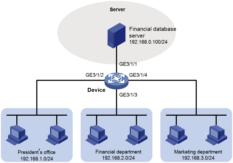
Network configuration
A company interconnects its departments through the device. Configure a packet filter to:
· Permit access from the President's office at any time to the financial database server.
· Permit access from the Finance department to the database server only during working hours (from 8:00 to 18:00) on working days.
· Deny access from any other department to the database server.
Figure 1 Network diagram
Procedure
# Create a periodic time range from 8:00 to 18:00 on working days.
<Device> system-view
[Device] time-range work 08:0 to 18:00 working-day
# Create an IPv4 advanced ACL numbered 3000.
[Device] acl advanced 3000
# Configure a rule to permit access from the President's office to the financial database server.
[Device-acl-ipv4-adv-3000] rule permit ip source 192.168.1.0 0.0.0.255 destination 192.168.0.100 0
# Configure a rule to permit access from the Finance department to the database server during working hours.
[Device-acl-ipv4-adv-3000] rule permit ip source 192.168.2.0 0.0.0.255 destination 192.168.0.100 0 time-range work
# Configure a rule to deny access to the financial database server.
[Device-acl-ipv4-adv-3000] rule deny ip source any destination 192.168.0.100 0
[Device-acl-ipv4-adv-3000] quit
# Apply IPv4 advanced ACL 3000 to filter outgoing packets on interface Ten-GigabitEthernet 3/1/1.
[Device] interface ten-gigabitethernet 3/1/1
[Device-Ten-GigabitEthernet3/1/1] packet-filter 3000 outbound
[Device-Ten-GigabitEthernet3/1/1] quit
Verifying the configuration
# Verify that a PC in the Finance department can ping the database server during working hours. (All PCs in this example use Windows XP).
C:\> ping 192.168.0.100
Pinging 192.168.0.100 with 32 bytes of data:
Reply from 192.168.0.100: bytes=32 time=1ms TTL=255
Reply from 192.168.0.100: bytes=32 time<1ms TTL=255
Reply from 192.168.0.100: bytes=32 time<1ms TTL=255
Reply from 192.168.0.100: bytes=32 time<1ms TTL=255
Ping statistics for 192.168.0.100:
Packets: Sent = 4, Received = 4, Lost = 0 (0% loss),
Approximate round trip times in milli-seconds:
Minimum = 0ms, Maximum = 1ms, Average = 0ms
# Verify that a PC in the Marketing department cannot ping the database server during working hours.
C:\> ping 192.168.0.100
Pinging 192.168.0.100 with 32 bytes of data:
Request timed out.
Request timed out.
Request timed out.
Request timed out.
Ping statistics for 192.168.0.100:
Packets: Sent = 4, Received = 0, Lost = 4 (100% loss),
# Display configuration and match statistics for IPv4 advanced ACL 3000 on the device during working hours.
[Device] display acl 3000
Advanced IPv4 ACL 3000, 3 rules,
ACL's step is 5
rule 0 permit ip source 192.168.1.0 0.0.0.255 destination 192.168.0.100 0
rule 5 permit ip source 192.168.2.0 0.0.0.255 destination 192.168.0.100 0 time-range work (Active)
rule 10 deny ip destination 192.168.0.100 0
The output shows that rule 5 is active. Rule 5 and rule 10 have been matched four times as the result of the ping operations.
