- Table of Contents
-
- 04-Layer 2—LAN Switching Configuration Guide
- 00-Preface
- 01-MAC address table configuration
- 02-Ethernet link aggregation configuration
- 03-VLAN configuration
- 04-MVRP configuration
- 05-QinQ configuration
- 06-VLAN mapping configuration
- 07-VLAN termination configuration
- 08-Loop detection configuration
- 09-Spanning tree configuration
- 10-LLDP configuration
- Related Documents
-
| Title | Size | Download |
|---|---|---|
| 06-VLAN mapping configuration | 101.46 KB |
Contents
VLAN mapping application scenarios
Restrictions and guidelines: VLAN mapping configuration
Configuring one-to-one VLAN mapping
Display and maintenance commands for VLAN mapping
Configuring VLAN mapping
About VLAN mapping
VLAN mapping re-marks VLAN traffic with new VLAN IDs.
VLAN mapping application scenarios
As shown in Figure 1, the CVLAN and SVLAN are different between the customer network and the service provider network. To transmit packets from the customer network to the service provider network, use one-to-one VLAN mapping on the customer-side port of a PE to replace the CVLAN with a VLAN tag supported by the service provider network.
Figure 1 Application scenario of one-to-one VLAN mapping
VLAN mapping implementations
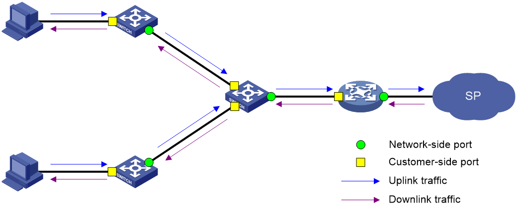
Figure 2 shows a simplified network that illustrates basic VLAN mapping terms.
Basic VLAN mapping terms include the following:
· Uplink traffic—Traffic transmitted from the customer network to the service provider network.
· Downlink traffic—Traffic transmitted from the service provider network to the customer network.
· Network-side port—A port connected to or closer to the service provider network.
· Customer-side port—A port connected to or closer to the customer network.
Figure 2 Basic VLAN mapping terms
One-to-one VLAN mapping
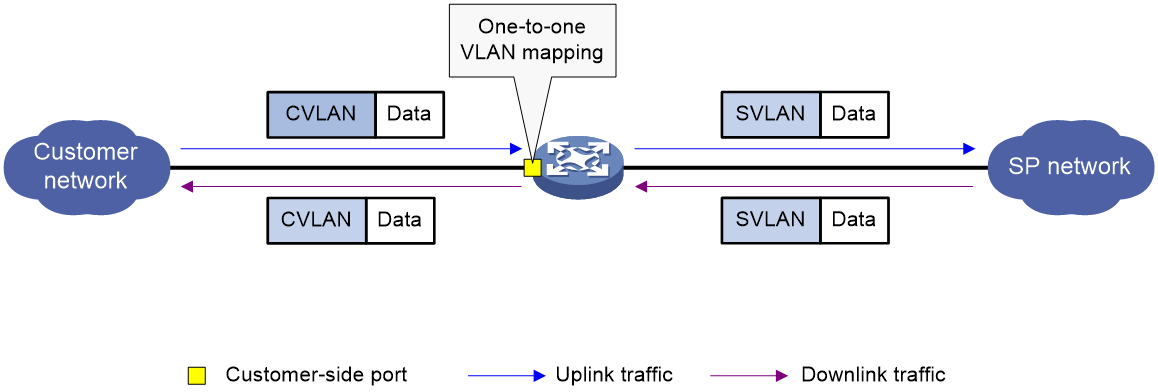
As shown in Figure 3, one-to-one VLAN mapping is implemented on the customer-side port and replaces VLAN tags as follows:
· Replaces the CVLAN with the SVLAN for the uplink traffic.
· Replaces the SVLAN with the CVLAN for the downlink traffic.
Figure 3 One-to-one VLAN mapping implementation
Restrictions and guidelines: VLAN mapping configuration
To add or replace VLAN tags for packets, you can configure both VLAN mapping and a QoS policy. The QoS policy takes effect if a configuration conflict occurs. For information about QoS policies, see ACL and QoS Configuration Guide.
Prerequisites
Before you configure VLAN mapping, create original and translated VLANs.
Configuring one-to-one VLAN mapping
About this task
Configure one-to-one VLAN mapping on the customer-side ports of the PE in the service provider network (see Figure 1) to isolate traffic of the same service type from different homes.
Procedure
1. Enter system view.
system-view
2. Enter interface view.
¡ Enter Layer 2 Ethernet interface view.
interface interface-type interface-number
¡ Enter Layer 2 aggregate interface view.
interface bridge-aggregation interface-number
3. Set the link type of the port.
port link-type { hybrid | trunk }
By default, the link type of a port is access.
4. Assign the port to the original VLAN and the translated VLAN.
¡ Assign the trunk port to the original VLAN and the translated VLAN.
port trunk permit vlan vlan-id-list
By default, a trunk port is assigned to VLAN 1.
¡ Assign the hybrid port to the original VLAN and the translated VLAN as a tagged member.
port hybrid vlan vlan-id-list tagged
By default, a hybrid port is an untagged member of the VLAN to which the port belongs when its link type is access.
5. Configure a one-to-one VLAN mapping.
vlan mapping vlan-id translated-vlan vlan-id
By default, no VLAN mapping is configured on an interface.
Display and maintenance commands for VLAN mapping
Execute display commands in any view.
|
Task |
Command |
|
Display VLAN mapping information. |
display vlan mapping [ interface interface-type interface-number ] |
VLAN mapping configuration examples
Example: Configuring one-to-one VLAN mapping
Network configuration
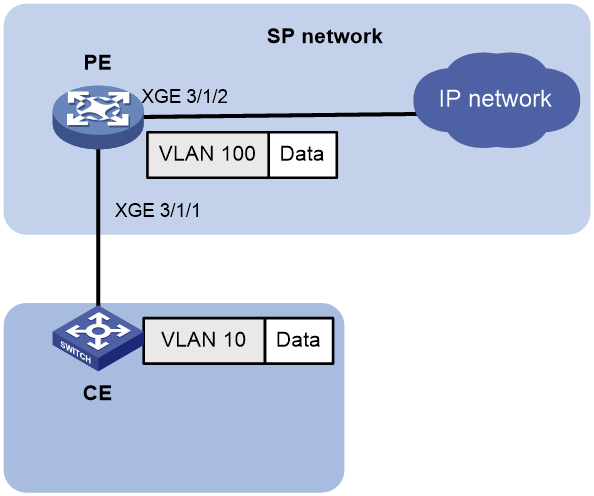
As shown in Figure 4:
· Traffic is transmitted from the customer side network to the service provider network through a PE.
· To allow traffic to be fowarded in the service provider network, configure one-to-one VLAN mapping on the customer-side port of the PE to map VLAN 10 to VLAN 100.

Procedure
# Create VLAN 10 as an original VLAN and VLAN 100 as a translated VLAN on the PE.
<PE> system-view
[PE] vlan 10
[PE-vlan10] quit
[PE] vlan 100
[PE-vlan100] quit
# Configure customer-side port Ten-GigabitEthernet 3/1/1 as a trunk port.
[PE] interface ten-gigabitethernet 3/1/1
[PE-Ten-GigabitEthernet3/1/1] port link-type trunk
# Assign Ten-GigabitEthernet 3/1/1 to VLAN 10 and translated VLAN 100.
[PE-Ten-GigabitEthernet3/1/1] port trunk permit vlan 10 100
# Configure a one-to-one VLAN mapping on Ten-GigabitEthernet 3/1/1 to map VLAN 10 to VLAN 100.
[PE-Ten-GigabitEthernet3/1/1] vlan mapping 10 translated-vlan 100
[PE-Ten-GigabitEthernet3/1/1] quit
# Configure the network-side port Ten-GigabitEthernet 3/1/2 as a trunk port.
[PE] interface ten-gigabitethernet 3/1/2
[PE-Ten-GigabitEthernet3/1/2] port link-type trunk
# Assign Ten-GigabitEthernet 3/1/2 to VLAN 100.
[PE-Ten-GigabitEthernet3/1/2] port trunk permit vlan 100
[PE-Ten-GigabitEthernet3/1/2] quit
Verifying the configuration
# Verify VLAN mapping information on the PE.
[PE] display vlan mapping
Interface Ten-GigabitEthernet3/1/1:
Outer VLAN Inner VLAN Translated Outer VLAN Translated Inner VLAN
10 N/A 100 N/A
