- Table of Contents
-
- 12-Security Configuration Guide
- 00-Preface
- 01-DAE proxy configuration
- 02-Password control configuration
- 03-Keychain configuration
- 04-Public key management
- 05-PKI configuration
- 06-IPsec configuration
- 07-SSH configuration
- 08-SSL configuration
- 09-Session management
- 10-Object group configuration
- 11-Attack detection and prevention configuration
- 12-IP-based attack prevention configuration
- 13-IP source guard configuration
- 14-ARP attack protection configuration
- 15-ND attack defense configuration
- 16-uRPF configuration
- 17-SAVA configuration
- 18-SAVA-P configuration
- 19-Crypto engine configuration
- 20-Trust level configuration
- Related Documents
-
| Title | Size | Download |
|---|---|---|
| 17-SAVA configuration | 248.08 KB |
Content
Enabling SAVA entry creation based on synchronized remote routes
Adding an interface to a SAVA access group
Configuring dropping of SAVA-detected spoofing packets
Display and maintenance commands for SAVA
Example: Configuring SAVA on border devices directly connected the LAN
Example: Configuring SAVA on border devices indirectly connected the LAN (OSPFv3)
Example: Configuring SAVA on border devices indirectly connected the LAN (IPv6 IS-IS)
Example: Configuring SAVA on inter-AS border devices indirectly connected the LAN
Configuring SAVA
About SAVA
Benefits
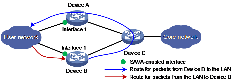
As shown in Figure 1, asymmetric routing might occur in an IPv6 multiple-access network. The outgoing interface for a return packet might be different from the incoming interface of the original packet. You can enable strict uRPF check on interface 1 of Device B to prevent attacks with spoofed source IPv6 addresses. However, strict uRPF check might determine that a valid packet from the LAN as an attack packet based on local routing information, which causes unexpected packet drop.
Figure 1 SAVA-enabled network
Mechanism
Obtaining prefixes of valid users
Creating SAVA entries
Filtering user packets based on SAVA entries
Application scenarios
Deployed on intra-AS border devices directedly connected to the LAN
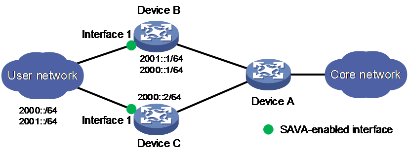
As shown in Figure 2, users in the LAN connect to the backbone network through Device B and Device C. Device B is configured with two gateways addresses (2000::1/64 and 2001::1/64). Device C is configured with the gateway address (2000::2/64).
Figure 2 SAVA deployed on border devices directly connected to the LAN
Deployed on intra-AS border devices indirectedly connected to the LAN
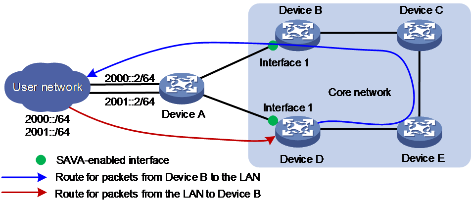
As shown in Figure 3, asymmetric traffic exists between Device D and the LAN after route convergence. Traffic from Device D to the LAN will traverse Device E, Device C, Device B, and Device A. Traffic from the LAN to Device D will traverse only Device A.
Figure 3 SAVA deployed on intra-AS border devices indirectly connected to the LAN
Deployed on inter-AS border devices indirectedly connected to the LAN
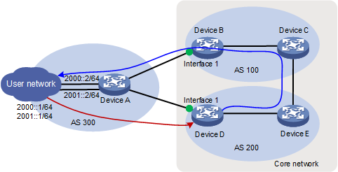
As shown in Figure 4, asymmetric traffic exists between Device D and the LAN after route convergence. Traffic from Device D to the LAN will traverse Device E, Device C, Device B, and Device A. Traffic from the LAN to Device D will traverse only Device A.
Figure 4 SAVA deployed on inter-AS border devices indirectly connected to the LAN
SAVA tasks at a glance
To configure SAVA, perform the following tasks:
2. Enabling SAVA entry creation based on synchronized remote routes
Perform this task if the LAN connects to the backbone network through multiple border devices and interfaces on the border devices do not have prefix information of all user in the LAN.
3. Adding an interface to a SAVA access group
Perform this task if a border device has multiple interfaces connected to the same LAN.
4. (Optional.) Configuring dropping of SAVA-detected spoofing packets
5. (Optional.) Configuring SAVA logging
Enabling SAVA
Restrictions and guidelines
Procedure
1. Enter system view.
system-view
2. Enter interface view.
interface interface-type interface-number
3. Enable SAVA on the interface.
By default, SAVA is disabled.
Enabling SAVA entry creation based on synchronized remote routes
About this task
Prerequisites
· Configure OSPFv3 link tag inheritance
Perform this task if OSPFv3 runs on the network. For more information about OSPFv3 link tag inheritance, see OSPFv3 configuration in Layer 3—IP Routing Configuration Guide.
· Configure IPv6 IS-IS link tag inheritance
Perform this task if IPv6 IS-IS runs on the network. For more information about IPv6 IS-IS link tag inheritance, see IS-IS configuration in Layer 3—IP Routing Configuration Guide.
Procedure
1. Enter system view.
system-view
2. Enter interface view.
interface interface-type interface-number
3. Enable the device to create SAVA entries based on synchronized remote routes with the specified route tag.
ipv6 sava import remote-route-tag tag
By default, the device does not create SAVA entries based on synchronized remote routes.
Adding an interface to a SAVA access group
About this task
Restrictions and guidelines
All interfaces in a SAVA access group must belong to the public network or the same VPN instance.
You can add a maximum of eight interfaces to a SAVA access group.
Procedure
1. Enter system view.
system-view
2. Enter interface view.
interface interface-type interface-number
3. Add the interface to a SAVA access group.
ipv6 sava access-group group-name
By default, an interface does not belong to a SAVA access group.
Configuring dropping of SAVA-detected spoofing packets
Restrictions and guidelines
By default, when a SAVA-enabled interface receives an IPv6 packet and no matching SAVA entry containing the packet's source IPv6 address exists on the device, the packet is dropped. The device creates SAVA entries based on corresponding routing entries. If the device has a large number of routing entries, it might take a long time for the device to complete SAVA entry creation. Before SAVA entry creation completes, valid IPv6 packets might be dropped. To resolve this issue, use the undo ipv6 sava packet-drop enable command to disable dropping of SAVA-detected spoofing packets. In this way, before enabling dropping of SAVA-detected spoofing packets, you can analyze and adjust network configurations according to the output spoofing packet logs.
Procedure
1. Enter system view.
system-view
2. Enable dropping of SAVA-detected spoofing packets.
ipv6 sava packet-drop enable
By default, dropping of SAVA-detected spoofing packets is enabled.
Configuring SAVA logging
About this task
To identify and troubleshoot issues, enable SAVA logging.
This feature enables the device to generate SAVA logs when SAVA detects spoofing packets.
Procedure
1. Enter system view.
system-view
2. Configure SAVA logging.
ipv6 sava log enable spoofing-packet [ interval interval | number number ]*
By default, SAVA logging is disabled.
Display and maintenance commands for SAVA
Execute display commands in any view and reset commands in user view.
|
Task |
Command |
|
Display SAVA entries. |
display ipv6 sava [ interface interface-type interface-number ] [ slot slot-number ] |
|
Display SAVA packet drop statistics. |
display ipv6 sava packet-drop statistics [ interface interface-type interface-number ] |
|
Clear SAVA packet drop statistics |
reset ipv6 sava packet-drop statistics [ interface interface-type interface-number ] |
SAVA configuration examples
Example: Configuring SAVA on border devices directly connected the LAN
Network configuration
As shown in Figure 5, legal users in the LAN use prefixes 2000::/64 and 2001::/64. Configure SAVA on Ten-GigabitEthernet3/0/1 of Device B and Device C to meet the following requirements:
Device C creates a SAVA entry upon receiving an IPv6 route with prefix 2001::/64.
The LAN-side interface on Device C filters packets from users in the LAN based on SAVA entries.
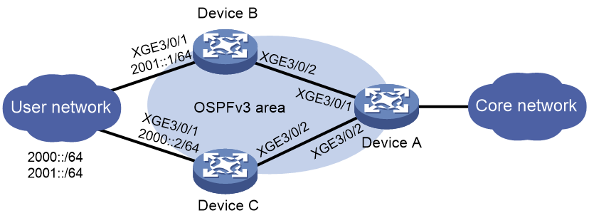
Table 1 Interface and IP address assignment
|
Device |
Interface |
IP address |
Device |
Interface |
IP address |
|
Device A |
XGE3/0/1 |
192:168::12:1/120 |
Device B |
XGE3/0/1 |
2001::1/64 |
|
Device A |
XGE3/0/2 |
192:168::22:1/120 |
Device B |
XGE3/0/2 |
192:168::22:2/120 |
|
Device C |
XGE3/0/1 |
2000::2/64 |
— |
— |
— |
|
Device C |
XGE3/0/2 |
192:168::12:2/120 |
— |
— |
— |
Prerequisites
1. Assign IPv6 addresses to interfaces on the devices.
2. Configure OSPFv3 on the backbone network. For more information, see OSPFv3 configuration in Layer 3—IP Routing Configuration Guide.
Procedure
1. Configure Device B:
# Enable SAVA on Ten-GigabitEthernet3/0/1 (the LAN-side interface).
<DeviceB> system-view
[DeviceB] interface ten-gigabitethernet 3/0/1
[DeviceB-Ten-GigabitEthernet3/0/1] ipv6 sava enable
# Configure routing policy named ttt, configure node 10 in permit mode to permit routes with the output interface Ten-GigabitEthernet3/0/1 and to set a tag of 100 for IGP routes.
[DeviceB] route-policy ttt permit node 10
[DeviceB-route-policy-ttt-10] if-match interface ten-gigabitethernet 3/0/1
[DeviceB-route-policy-ttt-10] apply tag 100
[DeviceB-route-policy-ttt-10] quit
# Configure OSPFv3 process 1 to redistribute direct routes permitted by routing policy ttt.
[DeviceB] ospfv3 1
[DeviceB-ospfv3-1] import-route direct route-policy ttt
[DeviceB-ospfv3-1] quit
2. Configure Device C:
# Enable SAVA on Ten-GigabitEthernet3/0/1 (the LAN-side interface).
<DeviceC> system-view
[DeviceC] interface ten-gigabitethernet 3/0/1
[DeviceC-Ten-GigabitEthernet3/0/1] ipv6 sava enable
# Configure Ten-GigabitEthernet3/0/1 to redistribute remote routes with route tag 100.
[DeviceC-Ten-GigabitEthernet3/0/1] ipv6 sava import remote-tag 100
[DeviceC-Ten-GigabitEthernet3/0/1] quit
Verifying the configuration
# Display SAVA entries on Device C.
[DeviceC] display ipv6 sava
IPv6 SAVA entry count: 2
Destination: 2000:: Prefix length: 64
Interface: XGE3/0/1 Flags: L
VPN instance: --
Destination: 2001:: Prefix length: 64
Interface: XGE3/0/1 Flags: R
The output shows that Device C created a SAVA entry with prefix 2001::. When Device C receives an IPv6 packet with prefix 2001:: on Ten-GigabitEthernet3/0/1, it will forward the packet.
Example: Configuring SAVA on border devices indirectly connected the LAN (OSPFv3)
Network configuration
As shown in Figure 6, OSPFv3 runs on the core network. Configure the devices to meet the following requirements:
Enable SAVA on Ten-GigabitEthernet3/0/1 of Device B and Device D to filter packets based on SAVA entries.

Table 2 Interface and IP address assignment
|
Device |
Interface |
IP address |
Device |
Interface |
IP address |
|
Device A |
XGE3/0/1 |
2001::2/64 |
Device B |
XGE3/0/1 |
192:168::12:2/120 |
|
Device A |
XGE3/0/2 |
2000::2/64 |
Device B |
XGE3/0/2 |
192:168::34:3/120 |
|
Device A |
XGE3/0/3 |
192:168::12:1/120 |
— |
— |
— |
|
Device A |
XGE3/0/4 |
192:168::22:1/120 |
— |
— |
— |
|
Device C |
XGE3/0/1 |
192:168::34:4/120 |
Device D |
XGE3/0/1 |
192:168::22:2/120 |
|
Device C |
XGE3/0/2 |
192:168::46:4/120 |
Device D |
XGE3/0/2 |
192:168::56:5/120 |
|
Device E |
XGE3/0/1 |
192:168::56:6/120 |
— |
— |
— |
|
Device E |
XGE3/0/2 |
192:168::46:6/120 |
— |
— |
— |
Prerequisites
Assign IPv6 addresses to interfaces on the devices.
Procedure
1. Configure Device A:
# Configure OSPFv3.
<DeviceA> system-view
[DeviceA] ospfv3 1
[DeviceA-ospfv3-1] router-id 1.1.1.1
[DeviceA-ospfv3-1] quit
[DeviceA] interface ten-gigabitethernet 3/0/1
[DeviceA-Ten-GigabitEthernet3/0/1] ospfv3 1 area 0.0.0.0
[DeviceA-Ten-GigabitEthernet3/0/1] quit
[DeviceA] interface ten-gigabitethernet 3/0/3
[DeviceA-Ten-GigabitEthernet3/0/3] ospfv3 1 area 0.0.0.0
[DeviceA-Ten-GigabitEthernet3/0/3] quit
2. Configure Device B:
# Configure OSPFv3.
<DeviceB> system-view
[DeviceB] ospfv3 1
[DeviceB-ospfv3-1] router-id 2.2.2.2
[DeviceB-ospfv3-1] quit
[DeviceB] interface ten-gigabitethernet 3/0/1
[DeviceB-Ten-GigabitEthernet3/0/1] ospfv3 1 area 0.0.0.0
[DeviceB-Ten-GigabitEthernet3/0/1] quit
[DeviceB] interface ten-gigabitethernet 3/0/2
[DeviceB-Ten-GigabitEthernet3/0/2] ospfv3 1 area 0.0.0.0
[DeviceB-Ten-GigabitEthernet3/0/2] quit
# Enable OSPFv3 link tag inheritance.
[DeviceB] ospfv3 1
[DeviceB-ospfv3-1] link-tag inherit enable
[DeviceB-ospfv3-1] quit
# Set the OSPFv3 link tag for Ten-GigabitEthernet3/0/1 to 100.
[DeviceB] interface ten-gigabitethernet 3/0/1
[DeviceB-Ten-GigabitEthernet3/0/1] ospfv3 link-tag 100
# Enable SAVA on Ten-GigabitEthernet3/0/1.
[DeviceB-Ten-GigabitEthernet3/0/1] ipv6 sava enable
# Configure Ten-GigabitEthernet3/0/1 to redistribute remote routes with route tag 100.
[DeviceB-Ten-GigabitEthernet3/0/1] ipv6 sava import remote-route-tag 100
[DeviceB-Ten-GigabitEthernet3/0/1] quit
3. Configure Device D:
# Configure a static route, whose destination address is 2000:: /64, next hop address is FE80::1 (a link-local IPv6 address on Device A), and tag value is 100.
<DeviceD> system-view
[DeviceD] ipv6 route-static 2000:: 64 ten-gigabitethernet 3/0/1 FE80::1 tag 100
# Configure routing policy named sava, configure node 10 in permit mode to permit routes with the output interface Ten-GigabitEthernet3/0/1.
[DeviceD] route-policy sava permit node 10
[DeviceD-route-policy-sava-10] if-match interface ten-gigabitethernet 3/0/1
[DeviceD-route-policy-sava-10] quit
# Configure OSPFv3.
[DeviceD] ospfv3 1
[DeviceD-ospfv3-1] router-id 4.4.4.4
[DeviceD-ospfv3-1] quit
[DeviceD] interface ten-gigabitethernet 3/0/2
[DeviceD-Ten-GigabitEthernet3/0/2] ospfv3 1 area 0.0.0.0
[DeviceD-Ten-GigabitEthernet3/0/2] quit
# Configure OSPFv3 process 1 to redistribute direct routes permitted by routing policy sava.
[DeviceD] ospfv3 1
[DeviceD-ospfv3-1] import-route static route-policy sava
# Enable OSPFv3 link tag inheritance.
[DeviceD-ospfv3-1] link-tag inherit enable
[DeviceD-ospfv3-1] quit
# Enable SAVA on Ten-GigabitEthernet3/0/1.
[DeviceD] interface ten-gigabitethernet 3/0/1
[DeviceD-Ten-GigabitEthernet3/0/1] ipv6 sava enable
# Configure Ten-GigabitEthernet3/0/1 to redistribute remote routes with route tag 100.
[DeviceD-Ten-GigabitEthernet3/0/1] ipv6 sava import remote-route-tag 100
[DeviceD-Ten-GigabitEthernet3/0/1] quit
4. Configure Device C:
# Configure OSPFv3.
<DeviceC> system-view
[DeviceC] ospfv3 1
[DeviceC-ospfv3-1] router-id 3.3.3.3
[DeviceC-ospfv3-1] quit
[DeviceC] interface ten-gigabitethernet 3/0/1
[DeviceC-Ten-GigabitEthernet3/0/1] ospfv3 1 area 0.0.0.0
[DeviceC-Ten-GigabitEthernet3/0/1] quit
[DeviceC] interface ten-gigabitethernet 3/0/2
[DeviceC-Ten-GigabitEthernet3/0/2] ospfv3 1 area 0.0.0.0
[DeviceC-Ten-GigabitEthernet3/0/2] quit
5. Configure Device E:
# Configure OSPFv3.
<DeviceE> system-view
[DeviceE] ospfv3 1
[DeviceE-ospfv3-1] router-id 5.5.5.5
[DeviceE-ospfv3-1] quit
[DeviceE] interface ten-gigabitethernet 3/0/1
[DeviceE-Ten-GigabitEthernet3/0/1] ospfv3 1 area 0.0.0.0
[DeviceE-Ten-GigabitEthernet3/0/1] quit
[DeviceE] interface ten-gigabitethernet 3/0/2
[DeviceE-Ten-GigabitEthernet3/0/2] ospfv3 1 area 0.0.0.0
[DeviceE-Ten-GigabitEthernet3/0/2] quit
Verifying the configuration
# Display SAVA entries on Device D.
[DeviceD] display ipv6 sava
IPv6 SAVA entry count: 4
Destination:192:168::12:0 Prefix length: 120
Interface: XGE3/0/1 Flags: R
VPN instance: --
Destination:192:168::22:0 Prefix length: 120
Interface: XGE3/0/1 Flags: L
VPN instance: --
Destination: 2000:: Prefix length: 64
Interface: XGE3/0/1 Flags: L
VPN instance: --
Destination: 2001:: Prefix length: 64
Interface: XGE3/0/1 Flags: R
The output shows that Device D created SAVA entries with prefix 2000:: and 2001::. When Device D receives an IPv6 packet with prefix 2000:: or 2001:: on Ten-GigabitEthernet3/0/1, it will forward the packet.
# Display SAVA entries on Device B.
[DeviceB] display ipv6 sava
IPv6 SAVA entry count: 3
Destination:192:168::12:0 Prefix length: 120
Interface: XGE3/0/1 Flags: L
VPN instance: --
Destination: 2000:: Prefix length: 64
Interface: XGE3/0/1 Flags: R
VPN instance: --
Destination: 2001:: Prefix length: 64
Interface: XGE3/0/1 Flags: L
The output shows that Device B created SAVA entries with prefix 2000:: and 2001::. When Device B receives an IPv6 packet with prefix 2000:: or 2001:: on Ten-GigabitEthernet3/0/1, it will forward the packet.
Example: Configuring SAVA on border devices indirectly connected the LAN (IPv6 IS-IS)
Network configuration
As shown in Figure 7, IPv6 IS-IS runs on the core network. Configure the devices to meet the following requirements:
Enable SAVA on Ten-GigabitEthernet3/0/1 of Device B and Device D to filter packets based on SAVA entries.
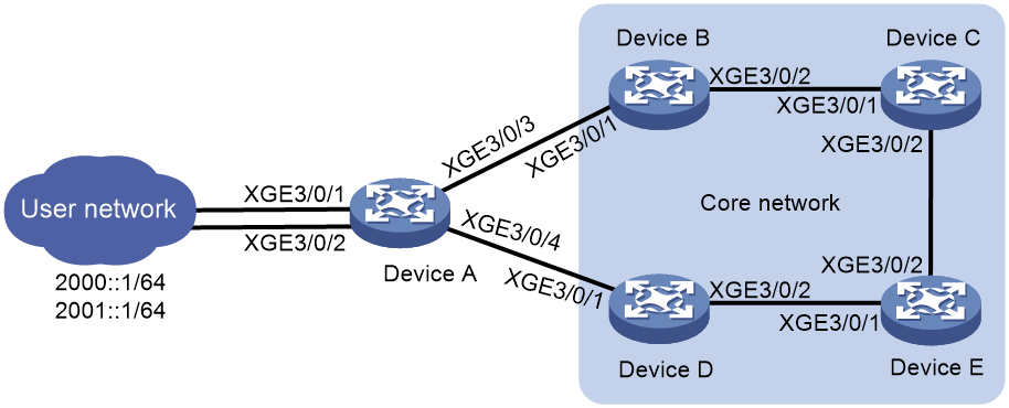
Table 3 Interface and IP address assignment
|
Device |
Interface |
IP address |
Device |
Interface |
IP address |
|
Device A |
XGE3/0/1 |
2001::2/64 |
Device B |
XGE3/0/1 |
192:168::12:2/120 |
|
Device A |
XGE3/0/2 |
2000::2/64 |
Device B |
XGE3/0/2 |
192:168::34:3/120 |
|
Device A |
XGE3/0/3 |
192:168::12:1/120 |
— |
— |
— |
|
Device A |
GE1/0/4 |
192:168::22:1/120 |
— |
— |
— |
|
Device C |
XGE3/0/1 |
192:168::34:4/120 |
Device D |
XGE3/0/1 |
192:168::22:2/120 |
|
Device C |
XGE3/0/2 |
192:168::46:4/120 |
Device D |
XGE3/0/2 |
192:168::56:5/120 |
|
Device E |
XGE3/0/1 |
192:168::56:6/120 |
— |
— |
— |
|
Device E |
XGE3/0/2 |
192:168::46:6/120 |
— |
— |
— |
Prerequisites
Assign IPv6 addresses to interfaces on the devices.
Procedure
1. Configure Device A:
# Configure IPv6 IS-IS.
<DeviceA> system-view
[DeviceA] isis 1
[DeviceA-isis-1] is-level level-2
[DeviceA-isis-1] network-entity 10.0000.0000.0001.00
[DeviceA-isis-1] cost-style wide
[DeviceA-isis-1] address-family ipv6
[DeviceA-isis-1-ipv6] quit
[DeviceA-isis-1] quit
[DeviceA] interface ten-gigabitethernet 3/0/1
[DeviceA-Ten-GigabitEthernet3/0/1] isis ipv6 enable 1
[DeviceA-Ten-GigabitEthernet3/0/1] quit
[DeviceA] interface ten-gigabitethernet 3/0/3
[DeviceA-Ten-GigabitEthernet3/0/3] isis ipv6 enable 1
[DeviceA-Ten-GigabitEthernet3/0/3] quit
2. Configure Device B:
# Configure IPv6 IS-IS.
<DeviceB> system-view
[DeviceB] isis 1
[DeviceB-isis-1] is-level level-2
[DeviceB-isis-1] network-entity 10.0000.0000.0002.00
[DeviceB-isis-1] cost-style wide
[DeviceB-isis-1] address-family ipv6
[DeviceB-isis-1-ipv6] quit
[DeviceB-isis-1] quit
[DeviceB] interface ten-gigabitethernet 3/0/1
[DeviceB-Ten-GigabitEthernet3/0/1] isis ipv6 enable 1
[DeviceB-Ten-GigabitEthernet3/0/1] quit
[DeviceB] interface ten-gigabitethernet 3/0/2
[DeviceB-Ten-GigabitEthernet3/0/2] isis ipv6 enable 1
[DeviceB-Ten-GigabitEthernet3/0/2] quit
# Enable IPv6 IS-IS link tag inheritance.
[DeviceB] isis 1
[DeviceB-isis-1] address-family ipv6
[DeviceB-isis-1-ipv6] link-tag inherit enable
[DeviceB-isis-1-ipv6] quit
[DeviceB-isis-1] quit
# Set the IPv6 IS-IS link tag for Ten-GigabitEthernet3/0/1 to 100.
[DeviceB] interface ten-gigabitethernet 3/0/1
[DeviceB-Ten-GigabitEthernet3/0/1] isis ipv6 link-tag 100
# Enable SAVA on Ten-GigabitEthernet3/0/1.
[DeviceB-Ten-GigabitEthernet3/0/1] ipv6 sava enable
# Configure Ten-GigabitEthernet3/0/1 to redistribute remote routes with route tag 100.
[DeviceB-Ten-GigabitEthernet3/0/1] ipv6 sava import remote-route-tag 100
[DeviceB-Ten-GigabitEthernet3/0/1] quit
3. Configure Device D:
# Configure a static route, whose destination address is 2000:: /64, next hop address is FE80::1 (a link-local IPv6 address on Device A), and tag value is 100.
<DeviceD> system-view
[DeviceD] ipv6 route-static 2000:: 64 ten-gigabitethernet 3/0/1 FE80::1 tag 100
# Configure routing policy named sava, configure node 10 in permit mode to permit routes with the output interface Ten-GigabitEthernet3/0/1.
[DeviceD] route-policy sava permit node 10
[DeviceD-route-policy-sava-10] if-match interface ten-gigabitethernet 3/0/1
[DeviceD-route-policy-sava-10] quit
# Configure IPv6 IS-IS.
[DeviceD] isis 1
[DeviceD-isis-1] is-level level-2
[DeviceD-isis-1] network-entity 10.0000.0000.0004.00
[DeviceD-isis-1] cost-style wide
[DeviceD-isis-1] address-family ipv6
[DeviceD-isis-1-ipv6] quit
[DeviceD-isis-1] quit
[DeviceD] interface ten-gigabitethernet 3/0/2
[DeviceD-Ten-GigabitEthernet3/0/2] isis ipv6 enable 1
[DeviceD-Ten-GigabitEthernet3/0/2] quit
# Configure IS-IS process 1 to redistribute direct routes permitted by routing policy sava.
[DeviceD] isis 1
[DeviceD-isis-1] address-family ipv6
[DeviceD-isis-1-ipv6] import-route static route-policy sava level-2
# Enable IPv6 IS-IS link tag inheritance.
[DeviceD-isis-1-ipv6] link-tag inherit enable
[DeviceD-isis-1-ipv6] quit
[DeviceD-isis-1] quit
# Enable SAVA on Ten-GigabitEthernet3/0/1.
[DeviceD] interface ten-gigabitethernet 3/0/1
[DeviceD-Ten-GigabitEthernet3/0/1] ipv6 sava enable
# Configure Ten-GigabitEthernet3/0/1 to redistribute remote routes with route tag 100.
[DeviceD-Ten-GigabitEthernet3/0/1] ipv6 sava import remote-route-tag 100
[DeviceD-Ten-GigabitEthernet3/0/1] quit
4. Configure Device C:
# Configure IPv6 IS-IS.
<DeviceC> system-view
[DeviceC] isis 1
[DeviceC-isis-1] is-level level-2
[DeviceC-isis-1] network-entity 10.0000.0000.0003.00
[DeviceC-isis-1] cost-style wide
[DeviceC-isis-1] address-family ipv6
[DeviceC-isis-1-ipv6] quit
[DeviceC-isis-1] quit
[DeviceC] interface ten-gigabitethernet 3/0/1
[DeviceC-Ten-GigabitEthernet3/0/1] isis ipv6 enable 1
[DeviceC-Ten-GigabitEthernet3/0/1] quit
[DeviceC] interface ten-gigabitethernet 3/0/2
[DeviceC-Ten-GigabitEthernet3/0/2] isis ipv6 enable 1
[DeviceC-Ten-GigabitEthernet3/0/2] quit
5. Configure Device E:
# Configure IPv6 IS-IS.
<DeviceE> system-view
[DeviceE] isis 1
[DeviceE-isis-1] is-level level-2
[DeviceE-isis-1] network-entity 10.0000.0000.0005.00
[DeviceE-isis-1] cost-style wide
[DeviceE-isis-1] address-family ipv6
[DeviceE-isis-1-ipv6] quit
[DeviceE-isis-1] quit
[DeviceE] interface ten-gigabitethernet 3/0/1
[DeviceE-Ten-GigabitEthernet3/0/1] isis ipv6 enable 1
[DeviceE-Ten-GigabitEthernet3/0/1] quit
[DeviceE] interface ten-gigabitethernet 3/0/2
[DeviceE-Ten-GigabitEthernet3/0/2] isis ipv6 enable 1
[DeviceE-Ten-GigabitEthernet3/0/2] quit
Verifying the configuration
# Display SAVA entries on Device D.
[DeviceD] display ipv6 sava
IPv6 SAVA entry count: 3
Destination:192:168::22:0 Prefix length: 120
Interface: XGE3/0/1 Flags: L
VPN instance: --
Destination: 2000:: Prefix length: 64
Interface: XGE3/0/1 Flags: L
VPN instance: --
Destination: 2001:: Prefix length: 64
Interface: XGE3/0/1 Flags: R
The output shows that Device D created SAVA entries with prefix 2000:: and 2001::. When Device D receives an IPv6 packet with prefix 2000:: or 2001:: on Ten-GigabitEthernet3/0/1, it will forward the packet.
# Display SAVA entries on Device B.
[DeviceB] display ipv6 sava
IPv6 SAVA entry count: 3
Destination:192:168::12:0 Prefix length: 120
Interface: XGE3/0/1 Flags: L
VPN instance: --
Destination: 2000:: Prefix length: 64
Interface: XGE3/0/1 Flags: R
VPN instance: --
Destination: 2001:: Prefix length: 64
Interface: XGE3/0/1 Flags: L
The output shows that Device B created SAVA entries with prefix 2000:: and 2001::. When Device D receives an IPv6 packet with prefix 2000:: or 2001:: on Ten-GigabitEthernet3/0/1, it will forward the packet.
Example: Configuring SAVA on inter-AS border devices indirectly connected the LAN
Network configuration
As shown in Figure 8, configure the devices to meet the following requirements:
Configure SAVA on Ten-GigabitEthernet3/0/1 of Device B and Device D to filter packets based on SAVA entries.
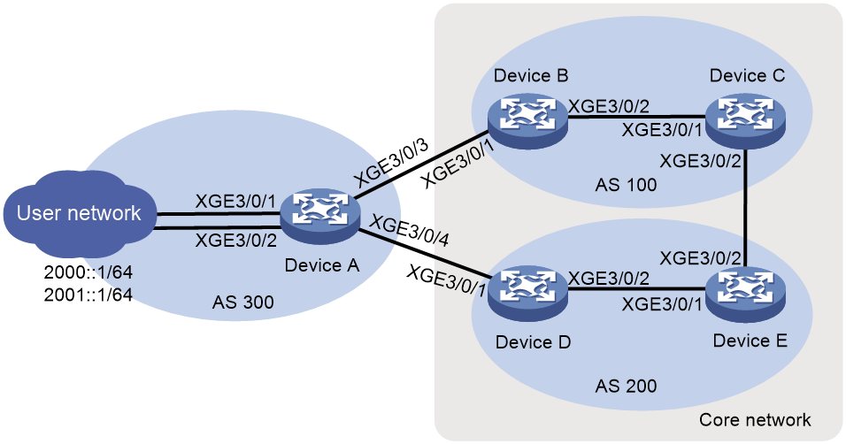
Table 4 Interface and IP address assignment
|
Device |
Interface |
IP address |
Device |
Interface |
IP address |
|
Device A |
XGE3/0/1 |
2001::2/64 |
Device B |
XGE3/0/1 |
192:168::12:2/120 |
|
Device A |
XGE3/0/2 |
2000::2/64 |
Device B |
XGE3/0/2 |
192:168::23:2/120 |
|
Device A |
XGE3/0/3 |
192:168::12:1/120 |
— |
— |
— |
|
Device A |
XGE3/0/4 |
192:168::22:1/120 |
— |
— |
— |
|
Device C |
XGE3/0/1 |
192:168::23:3/120 |
Device D |
XGE3/0/1 |
192:168::22:2/120 |
|
Device C |
XGE3/0/2 |
192:168::34:3/120 |
Device D |
XGE3/0/2 |
192:168::45:4/120 |
|
Device E |
XGE3/0/1 |
192:168::45:5/120 |
— |
— |
— |
|
Device E |
XGE3/0/2 |
192:168::34:4/120 |
— |
— |
— |
Prerequisites
Assign IPv6 addresses to interfaces on the devices.
Procedure
1. Configure Device B:
# Configure a static route, whose destination address is 2001:: 64, next hop address is FE80::1 (a link-local IPv6 address on Device A), and tag value is 100.
<DeviceB> system-view
[DeviceB] ipv6 route-static 2001:: 64 ten-gigabitethernet 3/0/1 FE80::1 tag 100
# Configure routing policy sava and configure node 10 in permit mode for the routing policy to permit routes with the output interface Ten-GigabitEthernet3/0/1.
[DeviceB] route-policy sava permit node 10
[DeviceB-route-policy-sava-10] if-match interface ten-gigabitethernet 3/0/1
[DeviceB-route-policy-sava-10] quit
# Configure OSPFv3.
[DeviceB] ospfv3 1
[DeviceB-ospfv3-1] router-id 2.2.2.2
[DeviceB-ospfv3-1] quit
[DeviceB] interface ten-gigabitethernet 3/0/3
[DeviceB-Ten-GigabitEthernet3/0/3] ospfv3 1 area 0.0.0.0
[DeviceB-Ten-GigabitEthernet3/0/3] quit
# Configure Ten-GigabitEthernet3/0/1 to redistribute remote routes with route tag 100.
[DeviceB] ospfv3 1
[DeviceB-ospfv3-1] import-route static route-policy sava
[DeviceB-ospfv3-1] quit
# Enable SAVA on Ten-GigabitEthernet3/0/1.
[DeviceB] interface ten-gigabitethernet 3/0/1
[DeviceB-Ten-GigabitEthernet3/0/1] ipv6 sava enable
# Configure Ten-GigabitEthernet3/0/1 to redistribute remote routes with route tag 100.
[DeviceB-Ten-GigabitEthernet3/0/1] ipv6 sava import remote-route-tag 100
[DeviceB-Ten-GigabitEthernet3/0/1] quit
2. Configure Device D:
# Configure a static route, whose destination address is 2000:: 64, next hop address is FE80::1 (a link-local IPv6 address on Device A), and tag value is 100.
<DeviceD> system-view
[DeviceD] ipv6 route-static 2000:: 64 ten-gigabitethernet 3/0/1 FE80::1 tag 100
# Configure routing policy named sava, configure node 10 in permit mode to permit routes with the output interface Ten-GigabitEthernet3/0/1.
[DeviceD] route-policy sava permit node 10
[DeviceD-route-policy-sava-10] if-match interface ten-gigabitethernet 3/0/1
[DeviceD-route-policy-sava-10] quit
# Configure OSPFv3.
[DeviceD] ospfv3 1
[DeviceD-ospfv3-1] router-id 4.4.4.4
[DeviceD-ospfv3-1] quit
[DeviceD] interface ten-gigabitethernet 3/0/2
[DeviceD-Ten-GigabitEthernet3/0/2] ospfv3 1 area 0.0.0.0
[DeviceD-Ten-GigabitEthernet3/0/2] quit
# Configure OSPFv3 process 1 to redistribute remote routes permitted by routing policy sava.
[DeviceD] ospfv3 1
[DeviceD-ospfv3-1] import-route static route-policy sava
[DeviceD-ospfv3-1] quit
# Enable SAVA on Ten-GigabitEthernet3/0/1.
[DeviceD] interface ten-gigabitethernet 3/0/1
[DeviceD-Ten-GigabitEthernet3/0/1] ipv6 sava enable
# Configure Ten-GigabitEthernet3/0/1 to redistribute remote routes with route tag 100.
[DeviceD-Ten-GigabitEthernet3/0/1] ipv6 sava import remote-route-tag 100
[DeviceD-Ten-GigabitEthernet3/0/1] quit
3. Configure Device C:
# Configure routing policy named sava-exp, configure node 0 in permit mode to permit routes with tag 100 and to set the 10:10 community attribute for BGP.
[DeviceC] route-policy sava-exp permit node 0
[DeviceC-route-policy-sava-exp-0] if-match tag 100
[DeviceC-route-policy-sava-exp-0] apply community 10:10
[DeviceC-route-policy-sava-exp-0] quit
# Enable BGP to exchange routing information for IPv6 address family with peer 192:168::34:4 in AS 200.
[DeviceC] bgp 100
[DeviceC-bgp-default] router-id 3.3.3.3
[DeviceC-bgp-default] peer 192:168::34:4 as 200
[DeviceC-bgp-default] address-family ipv6
[DeviceC-bgp-default-ipv6] peer 192:168::34:4 enable
[DeviceC-bgp-default-ipv6] peer 192:168::34:4 advertise-community
# Configure BGP to redistribute routes from OSPFv3 process 1, and apply routing policy sava-exp to routes outgoing to peer 192:168::34:4.
[DeviceC-bgp-default-ipv6] import-route ospfv3 1
[DeviceC-bgp-default-ipv6] peer 192:168::34:4 route-policy sava-exp export
[DeviceC-bgp-default-ipv6] quit
[DeviceC-bgp-default] quit
# Configure basic community list 1 to permit routes with the 10:10 community attribute.
[DeviceC] ip community-list 1 permit 10:10
# Configure a routing policy named sava-imp, and configure node 10 in permit mode for the routing policy to use community list 1 to match BGP routes and to set the tag to 100.
[DeviceC] ip community-list 1 permit 10:10
[DeviceC] route-policy sava-imp permit node 0
[DeviceC-route-policy-sava-imp-0] if-match community 1
[DeviceC-route-policy-sava-imp-0] apply tag 100
[DeviceC-route-policy-sava-imp-0] quit
# Apply routing policy sava-imp to routes incoming from peer 192:168::34:4.
[DeviceC] bgp 100
[DeviceC-bgp-default] address-family ipv6
[DeviceC-bgp-default-ipv6] peer 192:168::34:4 route-policy sava-imp import
[DeviceC-bgp-default-ipv6] quit
[DeviceC-bgp-default] quit
# Configure OSPFv3.
[DeviceC] ospfv3 1
[DeviceC-ospfv3-1] router-id 3.3.3.3
[DeviceC-ospfv3-1] quit
[DeviceC] interface ten-gigabitethernet 3/0/1
[DeviceC-Ten-GigabitEthernet3/0/1] ospfv3 1 area 0.0.0.0
[DeviceC-Ten-GigabitEthernet3/0/1] quit
# Configure OSPFv3 process 1 to redistribute routes from IPv6 BGP.
[DeviceC] ospfv3 1
[DeviceC-ospfv3-1] import-route bgp4+
[DeviceC-ospfv3-1] quit
4. Configure Device E:
# Configure routing policy named sava-exp, configure node 0 in permit mode to permit routes with tag 100 and to set the 10:10 community attribute for BGP.
[DeviceE] route-policy sava-exp permit node 0
[DeviceE-route-policy-sava-exp-0] if-match tag 100
[DeviceE-route-policy-sava-exp-0] apply community 10:10
[DeviceE-route-policy-sava-exp-0] quit
# Enable BGP to exchange routing information for IPv6 address family with peer 192:168::34:3 in AS 100.
[DeviceE] bgp 200
[DeviceE-bgp-default] router-id 5.5.5.5
[DeviceE-bgp-default] peer 192:168::34:3 as 100
[DeviceE-bgp-default] address-family ipv6
[DeviceE-bgp-default-ipv6] peer 192:168::34:3 enable
[DeviceE-bgp-default-ipv6] peer 192:168::34:3 advertise-community
# Configure BGP to redistribute routes from OSPFv3 process 1, and apply routing policy sava-exp to routes outgoing to peer 192:168::34:3.
[DeviceE-bgp-default-ipv6] import-route ospfv3
[DeviceE-bgp-default-ipv6] peer 192:168::34:3 route-policy sava-exp export
[DeviceE-bgp-default-ipv6] quit
[DeviceE-bgp-default] quit
# Configure basic community list 1 to permit routes with the 10:10 community attribute.
[DeviceE] ip community-list 1 permit 10:10
# Configure a routing policy named sava-imp, and configure node 10 in permit mode for the routing policy to use community list 1 to match BGP routes and to set the tag to 100.
[DeviceE] route-policy sava-imp permit node 0
[DeviceE-route-policy-sava-imp-0] if-match community 1
[DeviceE-route-policy-sava-imp-0] apply tag 100
[DeviceE-route-policy-sava-imp-0] quit
# Apply routing policy sava-imp to routes incoming from peer 192:168::34:4.
[DeviceE] bgp 200
[DeviceE-bgp-default] address-family ipv6
[DeviceE-bgp-default-ipv6] peer 192:168::34:3 route-policy sava-imp import
[DeviceE-bgp-default-ipv6] quit
[DeviceE-bgp-default] quit
# Configure OSPFv3.
[DeviceE] ospfv3 1
[DeviceE-ospfv3-1] router-id 5.5.5.5
[DeviceE-ospfv3-1] quit
[DeviceE] interface ten-gigabitethernet 3/0/1
[DeviceE-Ten-GigabitEthernet3/0/1] ospfv3 1 area 0.0.0.0
[DeviceE-Ten-GigabitEthernet3/0/1] quit
# Configure OSPFv3 process 1 to redistribute routes from IPv6 BGP.
[DeviceE] ospfv3 1
[DeviceE-ospfv3-1] import-route bgp4+
[DeviceE-ospfv3-1] quit
Verifying the configuration
# Display SAVA entries on Device D.
[DeviceD] display ipv6 sava
IPv6 SAVA entry count: 3
Destination:192:168::22:0 Prefix length: 120
Interface: XGE3/0/1 Flags: L
VPN instance: --
Destination: 2000:: Prefix length: 64
Interface: XGE3/0/1 Flags: L
VPN instance: --
Destination: 2001:: Prefix length: 64
Interface: XGE3/0/1 Flags: R
The output shows that Device D created SAVA entries with prefix 2000:: and 2001::. When Device D receives an IPv6 packet with prefix 2000:: or 2001:: on Ten-GigabitEthernet3/0/1, it will forward the packet.
# Display SAVA entries on Device B.
[DeviceB] display ipv6 sava
IPv6 SAVA entry count: 3
Destination:192:168::12:0 Prefix length: 120
Interface: XGE3/0/2 Flags: L
VPN instance: --
Destination: 2000:: Prefix length: 64
Interface: XGE3/0/2 Flags: R
VPN instance: --
Destination: 2001:: Prefix length: 64
The output shows that Device B created SAVA entries with prefix 2000:: and 2001::. When Device B receives an IPv6 packet with prefix 2000:: or 2001:: on Ten-GigabitEthernet3/0/1, it will forward the packet.
