- Table of Contents
- Related Documents
-
| Title | Size | Download |
|---|---|---|
| 01-Hardware Information and Specifications | 5.29 MB |
1 Product models and technical specifications
10/100/1000BASE-T autosensing Ethernet port
5G/2.5G/1000BASE-T autosensing Ethernet port
2.5G/1000/100BASE-T autosensing Ethernet port
10/5/2.5/1GBASE-T autosensing Ethernet port
1 Product models and technical specifications
Product models
This document is applicable to the S5130S-EI switch series. Table1-1 describes the S5130S-EI switch series models.
Table1-1 S5130S-EI switch series models
|
Model |
Product code (PID) |
|
Non-PoE switch models |
|
|
S5130S-10P-EI |
LS-5130S-10P-EI LS-5130S-10P-EI-GL LS-5130S-10P-EI-H1 |
|
S5130S-12TP-EI |
LS-5130S-12TP-EI LS-5130S-12TP-EI-GL LS-5130S-12TP-EI-H1 |
|
S5130S-20P-EI |
LS-5130S-20P-EI LS-5130S-20P-EI-GL LS-5130S-20P-EI-H1 |
|
S5130S-28P-EI |
LS-5130S-28P-EI LS-5130S-28P-EI-GL LS-5130S-28P-EI-H1 LS-5130S-28P-EI-H1-GL |
|
S5130S-28P-EI-M |
LS-5130S-28P-EI-M |
|
S5130S-28TP-EI |
LS-5130S-28TP-EI LS-5130S-28TP-EI-GL |
|
S5130S-52P-EI |
LS-5130S-52P-EI LS-5130S-52P-EI-GL LS-5130S-52P-EI-H1 LS-5130S-52P-EI-H1-GL |
|
S5130S-52P-EI-M |
LS-5130S-52P-EI-M |
|
S5130S-52TP-EI |
LS-5130S-52TP-EI LS-5130S-52TP-EI-GL |
|
S5130S-28S-EI |
LS-5130S-28S-EI LS-5130S-28S-EI-GL LS-5130S-28S-EI-H1 LS-5130S-28S-EI-H1-GL |
|
S5130S-28S-EI-M |
LS-5130S-28S-EI-M |
|
S5130S-28S-EI-DP |
LS-5130S-28S-EI-DP |
|
S5130S-52S-EI |
LS-5130S-52S-EI LS-5130S-52S-EI-GL LS-5130S-52S-EI-H1 LS-5130S-52S-EI-H1-GL |
|
S5130S-52S-EI-M |
LS-5130S-52S-EI-M |
|
S5130S-28F-EI |
LS-5130S-28F-EI LS-5130S-28F-EI-GL |
|
S5130S-52F-EI |
LS-5130S-52F-EI LS-5130S-52F-EI-GL |
|
S5130S-28MP-EI |
LS-5130S-28MP-EI LS-5130S-28MP-EI-GL |
|
S5130S-52MP-EI |
LS-5130S-52MP-EI LS-5130S-52MP-EI-GL |
|
S5130S-28PS-EI |
LS-5130S-28PS-EI LS-5130S-28PS-EI-GL |
|
S5130S-28ST-EI |
LS-5130S-28ST-EI LS-5130S-28ST-EI-GL |
|
S5130S-52ST-EI |
LS-5130S-52ST-EI LS-5130S-52ST-EI-GL |
|
PoE switch models |
|
|
S5130S-10P-HPWR-EI |
LS-5130S-10P-HPWR-EI LS-5130S-10P-HPWR-EI-GL LS-5130S-10P-HPWR-EI-H1 |
|
S5130S-12TP-HPWR-EI |
LS-5130S-12TP-HPWR-EI LS-5130S-12TP-HPWR-EI-GL LS-5130S-12TP-HPWR-EI-H1 |
|
S5130S-20P-PWR-EI |
LS-5130S-20P-PWR-EI LS-5130S-20P-PWR-EI-GL LS-5130S-20P-PWR-EI-H1 |
|
S5130S-28P-PWR-EI |
LS-5130S-28P-PWR-EI LS-5130S-28P-PWR-EI-GL LS-5130S-28P-PWR-EI-H1 |
|
S5130S-28P-HPWR-EI |
LS-5130S-28P-HPWR-EI LS-5130S-28P-HPWR-EI-GL |
|
S5130S-52P-PWR-EI |
LS-5130S-52P-PWR-EI LS-5130S-52P-PWR-EI-GL |
|
S5130S-16S-PWR-EI |
LS-5130S-16S-PWR-EI LS-5130S-16S-PWR-EI-GL |
|
S5130S-16S-UPWR-EI-Q |
LS-5130S-16S-UPWR-EI-Q |
|
S5130S-28S-PWR-EI |
LS-5130S-28S-PWR-EI LS-5130S-28S-PWR-EI-GL LS-5130S-28S-PWR-EI-H1 |
|
S5130S-28S-HPWR-EI |
LS-5130S-28S-HPWR-EI LS-5130S-28S-HPWR-EI-GL |
|
S5130S-28S-HPWR-EI-Q |
LS-5130S-28S-HPWR-EI-Q |
|
S5130S-28S-UPWR-EI-Q |
LS-5130S-28S-UPWR-EI-Q |
|
S5130S-52S-PWR-EI |
LS-5130S-52S-PWR-EI LS-5130S-52S-PWR-EI-GL |
|
S5130S-52P-PWR-EI-AC |
LS-5130S-52P-PWR-EI-AC LS-5130S-52P-PWR-EI-AC-GL |
|
S5130S-52S-PWR-EI-AC |
LS-5130S-52S-PWR-EI-AC LS-5130S-52S-PWR-EI-AC-GL |
|
S5130S-28P-HPWR-EI-AC |
LS-5130S-28P-HPWR-EI-AC LS-5130S-28P-HPWR-EI-AC-GL |
|
S5130S-28S-HPWR-EI-AC |
LS-5130S-28S-HPWR-EI-AC LS-5130S-28S-HPWR-EI-AC-GL |
|
S5130S-28MP-HPWR-EI |
LS-5130S-28MP-HPWR-EI LS-5130S-28MP-HPWR-EI-GL |
|
S5130S-10MS-UPWR-EI |
LS-5130S-10MS-UPWR-EI LS-5130S-10MS-UPWR-EI-GL |
|
S5130S-28ST-PWR-EI |
LS-5130S-28ST-PWR-EI LS-5130S-28ST-PWR-EI-GL |
|
S5130S-52ST-PWR-EI |
LS-5130S-52ST-PWR-EI LS-5130S-52ST-PWR-EI-GL |
|
|
NOTE: Switches of the same model but different PIDs might differ in hardware and software features. You can view the PID of a switch on the label located on its rear panel or top panel. |
Technical specifications
Non-PoE switch models
Table1-2 Technical specifications for non-PoE switch models (1)
|
Item |
S5130S-10P-EI |
S5130S-12TP-EI |
S5130S-20P-EI |
|
Dimensions (H × W × D) |
43.6 × 266 × 161 mm (1.72 × 10.47 × 6.34 in) |
43.6 × 266 × 161 mm (1.72 × 10.47 × 6.34 in) |
43.6 × 330 × 230 mm (1.72 × 12.99 × 9.06 in) |
|
Weight |
≤ 1.5 kg (3.31 lb) |
≤ 1.5 kg (3.31 lb) |
≤ 2 kg (4.41 lb) |
|
Console port |
1 × serial console port |
1 × serial console port |
1 × serial console port |
|
10/100/1000BASE-T autosensing Ethernet port |
8 |
10 (The two highest-numbered 10/100/1000BASE-T autosensing Ethernet ports form combo interfaces with their corresponding SFP ports, respectively.) |
16 |
|
SFP port |
2 |
4 (The two lowest-numbered SFP ports form combo interfaces with their corresponding 10/100/1000BASE-T autosensing Ethernet ports, respectively.) |
4 |
|
Input voltage |
· Rated voltage: 100 VAC to 240 VAC @ 50 or 60 Hz · Max voltage: 90 VAC to 264 VAC @ 47 to 63 Hz |
||
|
Minimum power consumption |
7 W |
8 W |
9 W |
|
Maximum power consumption |
12 W |
15 W |
19 W |
|
Chassis leakage current compliance |
UL 62368-1/EN 62368-1/IEC 62368-1/UL 60950-1/EN 60950-1/IEC 60950-1/GB4943.1 |
||
|
Melting current of power supply fuse |
2 A/250 V |
2 A/250 V |
2 A/250 V |
|
Cooling system |
Passive cooling |
Passive cooling |
Passive cooling |
|
Operating temperature |
–5°C to +45°C (23°F to 113°F) |
||
|
Operating humidity |
5% to 95%, noncondensing |
||
|
Fire resistance compliance |
UL 62368-1/EN 62368-1/IEC 62368-1/UL 60950-1/EN 60950-1/IEC 60950-1/GB4943.1 |
||
Table1-3 Technical specifications for non-PoE switch models (2)
|
Item |
S5130S-28P-EI |
S5130S-52P-EI |
|
Dimensions (H × W × D) |
43.6 × 440 × 160 mm (1.72 × 17.32 × 6.30 in) |
43.6 × 440 × 230 mm (1.72 × 17.32 × 9.06 in) |
|
Weight |
≤ 2.5 kg (5.51 lb) |
≤ 3.5 kg (7.72 lb) |
|
Console port |
1 × serial console port |
1 × serial console port |
|
10/100/1000BASE-T autosensing Ethernet port |
24 |
48 |
|
SFP port |
4 |
4 |
|
Input voltage |
· Rated voltage: 100 VAC to 240 VAC @ 50 or 60 Hz · Max voltage: 90 VAC to 264 VAC @ 47 to 63 Hz |
|
|
Minimum power consumption |
9 W |
18 W |
|
Maximum power consumption |
23 W |
41 W |
|
Chassis leakage current compliance |
UL 62368-1/EN 62368-1/IEC 62368-1/UL 60950-1/EN 60950-1/IEC 60950-1/GB4943.1 |
|
|
Melting current of power supply fuse |
2 A/250 V |
3.15 A/250 V |
|
Cooling system |
Passive cooling |
Using fixed fan trays to draw ambient air in from the left side and right side and exhaust heated air from the power supply side. |
|
Operating temperature |
–5°C to +45°C (23°F to 113°F) |
|
|
Operating humidity |
5% to 95%, noncondensing |
|
|
Fire resistance compliance |
UL 62368-1/EN 62368-1/IEC 62368-1/UL 60950-1/EN 60950-1/IEC 60950-1/GB4943.1 |
|
Table1-4 Technical specifications for non-PoE switch models (3)
|
Item |
S5130S-28TP-EI |
S5130S-52TP-EI |
S5130S-28S-EI |
S5130S-52S-EI |
|
|
Dimensions (H × W × D) |
43.6 × 440 × 160 mm (1.72 × 17.32 × 6.30 in) |
43.6 × 440 × 260 mm (1.72 × 17.32 × 10.24 in) |
43.6 × 440 × 160 mm (1.72 × 17.32 × 6.30 in) |
43.6 × 440 × 230 mm (1.72 × 17.32 × 9.06 in) |
|
|
Weight |
≤ 2 kg (4.41 lb) |
≤ 3.5 kg (7.72 lb) |
≤ 2.5 kg (5.51 lb) |
≤ 3.5 kg (7.72 lb) |
|
|
Console port |
· 1 × serial console port · 1 × micro USB console port When both ports are connected, only the micro USB console port is available. |
· 1 × serial console port · 1 × micro USB console port When both ports are connected, only the micro USB console port is available. |
· 1 × serial console port · 1 × micro USB console port When both ports are connected, only the micro USB console port is available. |
· 1 × serial console port · 1 × micro USB console port When both ports are connected, only the micro USB console port is available. |
|
|
10/100/1000BASE-T autosensing Ethernet port |
26 (The two highest-numbered 10/100/1000BASE-T autosensing Ethernet ports form combo interfaces with their corresponding SFP ports, respectively.) |
50 (The two highest-numbered 10/100/1000BASE-T autosensing Ethernet ports form combo interfaces with their corresponding SFP ports, respectively.) |
24 |
48 |
|
|
SFP port |
4 (The two lowest-numbered SFP ports form combo interfaces with their corresponding 10/100/1000BASE-T autosensing Ethernet ports, respectively.) |
4 (The two lowest-numbered SFP ports form combo interfaces with their corresponding 10/100/1000BASE-T autosensing Ethernet ports, respectively.) |
N/A |
N/A |
|
|
SFP+ port |
N/A |
N/A |
4 |
4 |
|
|
Input voltage |
· Rated voltage: 100 VAC to 240 VAC @ 50 or 60 Hz · Max voltage: 90 VAC to 264 VAC @ 47 to 63 Hz |
||||
|
Minimum power consumption |
10 W |
20 W |
10 W |
19 W |
|
|
Maximum power consumption |
24 W |
42 W |
24 W |
44 W |
|
|
Chassis leakage current compliance |
UL 62368-1/EN 62368-1/IEC 62368-1/UL 60950-1/EN 60950-1/IEC 60950-1/GB4943.1 |
||||
|
Melting current of power supply fuse |
2 A/250 V |
3.15 A/250 V |
2 A/250 V |
3.15 A/250 V |
|
|
Cooling system |
Passive cooling |
Using fixed fan trays to draw ambient air in from the left side and right side of the chassis and exhaust heated air out from the power supply side. |
· Models with product codes LS-5130S-28S- EI-H1 and LS-5130S-28S-EI-H1-GL: Passive cooling. · Other models: Using fixed fan trays to draw ambient air in from the left side, right side, and port side of the chassis and exhaust heated air out from the power supply side. |
Using fixed fan trays to draw ambient air in from the left side and right side and exhaust heated air out from the power supply side. |
|
|
Operating temperature |
–5°C to +45°C (23°F to 113°F) |
||||
|
Operating humidity |
5% to 95%, noncondensing |
||||
|
Fire resistance compliance |
UL 62368-1/EN 62368-1/IEC 62368-1/UL 60950-1/EN 60950-1/IEC 60950-1/GB4943.1 |
||||
Table1-5 Technical specifications for non-PoE switch models (4)
|
Item |
S5130S-28F-EI |
S5130S-52F-EI |
|
Dimensions (H × W × D) |
43.6 × 440 × 360 mm (1.72 × 17.32 × 14.17 in) |
43.6 × 440 × 360 mm (1.72 × 17.32 × 14.17 in) |
|
Weight |
≤ 6 kg (13.23 lb) |
≤ 6.5 kg (14.33 lb) |
|
Console port |
· 1 × serial console port · 1 × micro USB console port When both ports are connected, only the micro USB console port is available. |
· 1 × serial console port · 1 × micro USB console port When both ports are connected, only the micro USB console port is available. |
|
10/100/1000BASE-T autosensing Ethernet port |
8 (Each and its corresponding SFP port form a combo interface.) |
2 (Each and its corresponding SFP port form a combo interface.) |
|
SFP port |
24 (The eight highest-numbered SFP ports form combo interfaces with their corresponding 10/100/1000BASE-T autosensing Ethernet ports, respectively.) |
48 (The two highest-numbered SFP ports form combo interfaces with their corresponding 10/100/1000BASE-T autosensing Ethernet ports, respectively.) |
|
SFP+ port |
4 |
4 |
|
Power supply slot |
2, at the rear panel |
2, at the rear panel |
|
Input voltage |
CA-70A12: · Rated voltage: 100 VAC to 240 VAC @ 50 or 60 Hz · Max voltage: 90 VAC to 290 VAC @ 47 to 63 Hz PSR75-12A: · Rated voltage: ¡ 100 VAC to 240 VAC @ 50 or 60 Hz ¡ 240 VDC · Max voltage: ¡ 90 VAC to 290 VAC @ 47 to 63 Hz ¡ 180 to 320 VDC PSR150-A1: · Rated voltage: 100 VAC to 240 VAC @ 50 or 60 Hz · Max voltage: 90 VAC to 264 VAC @ 47 to 63 Hz PSR150-D1: · Rated voltage: –48 VDC to –60 VDC · Max voltage: –36 VDC to –72 VDC DC power source for the PSR150-D1 power supply: –48 VDC power source in the equipment room or an RPS (H3C RPS800-A or RPS1600-A) |
|
|
Minimum power consumption |
· 1 × CA-70A12: 15 W · 2 × CA-70A12: 17 W · 1 × PSR75-12A: 15 W · 2 × PSR75-12A: 17 W · 1 × PSR150-A1: 18 W · 1 × PSR150-D1: 18 W · 2 × PSR150-A1: 23 W · 2 × PSR150-D1: 22 W |
· 1 × CA-70A12: 26 W · 2 × CA-70A12 29 W · 1 × PSR75-12A: 26 W · 2 × PSR75-12A: 29 W · 1 × PSR150-A1: 27 W · 1 × PSR150-D1: 27 W · 2 × PSR150-A1: 32 W · 2 × PSR150-D1: 33 W |
|
Maximum power consumption |
· 1 × CA-70A12: 45 W · 2 × CA-70A12: 48 W · 1 × PSR75-12A: 45 W · 2 × PSR75-12A: 48 W · 1 × PSR150-A1: 48 W · 1 × PSR150-D1: 51 W · 2 × PSR150-A1: 55 W · 2 × PSR150-D1: 57 W |
· 1 × CA-70A12: 69 W · 2 × CA-70A12: 72 W · 1 × PSR75-12A: 69 W · 2 × PSR75-12A: 72 W · 1 × PSR150-A1: 74 W · 1 × PSR150-D1: 84 W · 2 × PSR150-A1: 95 W · 2 × PSR150-D1: 95 W |
|
Chassis leakage current compliance |
UL 62368-1/EN 62368-1/IEC 62368-1/UL 60950-1/EN 60950-1/IEC 60950-1/GB4943.1 |
|
|
Melting current of power supply fuse |
· CA-70A12: 10 A/250 V · PSR75-12A: 3.15 A/250 V · PSR150-A1: 6.3 A/250 V · PSR150-D1: 8 A/250 V |
|
|
Cooling system |
Using fixed fan trays to draw ambient air in from the left side and port side and exhaust heated air from the right side. |
|
|
Operating temperature |
–5°C to +45°C (23°F to 113°F) |
|
|
Operating humidity |
5% to 95%, noncondensing |
|
|
Fire resistance compliance |
UL 62368-1/EN 62368-1/IEC 62368-1/UL 60950-1/EN 60950-1/IEC 60950-1/GB4943.1 |
|
Table1-6 Technical specifications for non-PoE switch models (5)
|
Item |
S5130S-28MP-EI |
S5130S-52MP-EI |
|
|
Dimensions (H × W × D) |
43.6 × 440 ×160 mm (1.72 × 17.32 × 6.30 in) |
43.6 × 440 × 230 mm (1.72 × 17.32 × 9.06 in) |
|
|
Weight |
≤ 2.5 kg (5.51 lb) |
≤ 3.5 kg (7.72 lb) |
|
|
Console port |
· 1 × serial console port · 1 × micro USB console port When both ports are connected, only the micro USB console port is available. |
||
|
10/100/1000BASE-T autosensing Ethernet port |
24 |
48 |
|
|
5G/2.5G/1000BASE-T autosensing Ethernet port |
2 |
||
|
SFP port |
2 |
||
|
AC-input voltage |
· Rated voltage: 100 VAC to 240 VAC @ 50 or 60 Hz · Max voltage: 90 VAC to 264 VAC @ 47 to 63 Hz |
||
|
Minimum power consumption |
14 W |
22 W |
|
|
Maximum power consumption |
28 W |
46 W |
|
|
Chassis leakage current compliance |
UL 62368-1/EN 62368-1/IEC 62368-1/UL 60950-1/EN 60950-1/IEC 60950-1/GB4943.1 |
||
|
Melting current of power supply fuse |
3.15 A/250 V |
6.3 A/250 V |
|
|
Cooling system |
Using fixed fan trays to draw ambient air in from the left side of the chassis and exhaust heated air out from the power supply side. |
||
|
Operating temperature |
–5°C to +45°C (23°F to 113°F) |
||
|
Operating humidity |
5% to 95%, noncondensing |
||
|
Fire resistance compliance |
UL 62368-1/EN 62368-1/IEC 62368-1/UL 60950-1/EN 60950-1/IEC 60950-1/GB4943.1 |
||
Table1-7 Technical specifications for non-PoE switch models (6)
|
Item |
S5130S-28S-EI-DP |
S5130S-28ST-EI |
S5130S-52ST-EI |
S5130S-28PS-EI |
|
|
Dimensions (H × W × D) |
43.6 × 440 × 260 mm (1.72 × 17.32 × 10.24 in) |
43.6 × 440 ×160 mm (1.72 × 17.32 × 6.30 in) |
43.6 × 440 × 260 mm (1.72 × 17.32 × 10.24 in) |
43.6 × 440 × 360 mm (1.72 × 17.32 × 14.17 in) |
|
|
Weight |
≤ 3.5 kg (7.72 lb) |
≤ 2.5 kg (5.51 lb) |
≤ 4 kg (8.82 lb) |
≤ 4.5 kg (9.92 lb) |
|
|
Console port |
· 1 × serial console port · 1 × micro USB console port When both ports are connected, only the micro USB console port is available. |
1 × serial console port |
|||
|
10/100/1000BASE-T autosensing Ethernet port |
24 |
24 |
48 |
24 (The eight highest-numbered 10/100/1000BASE-T autosensing Ethernet ports form combo interfaces with their corresponding SFP ports, respectively.) |
|
|
10/5/2.5/1GBASE-T autosensing Ethernet port |
N/A |
2 |
2 |
N/A |
|
|
SFP port |
N/A |
N/A |
N/A |
8 (The eight SFP ports form combo interfaces with their corresponding 10/100/1000BASE-T autosensing Ethernet ports, respectively.) |
|
|
SFP+ port |
4 |
2 |
2 |
4 |
|
|
Input voltage |
AC power source: · Rated voltage: 100 VAC to 240 VAC @ 50 or 60 Hz · Max voltage: 90 VAC to 264 VAC @ 47 to 63 Hz DC power source (supported only by the S5130S-28PS-EI switch): · Rated voltage:–24 VDC to –48 VDC · Max voltage: –24 VDC to –48 VDC |
||||
|
Minimum power consumption |
Single AC input: 11 W Dual AC inputs: 15 W |
AC: 14 W |
AC: 22 W |
AC: 12 W DC: 11 W |
|
|
Maximum power consumption |
Single AC input: 25 W Dual AC inputs: 26 W |
AC: 36 W |
AC: 53 W |
AC: 31 W DC: 26 W |
|
|
Chassis leakage current compliance |
UL 62368-1/EN 62368-1/IEC 62368-1/UL 60950-1/EN 60950-1/IEC 60950-1/GB4943.1 |
||||
|
Melting current of power supply fuse |
2 A/250 V |
2 A/250 V |
2 A/250 V |
2 A/250 V |
|
|
Cooling system |
Using fixed fan trays to draw ambient air in from the chassis left side and exhaust heated air from the chassis right side. |
||||
|
Operating temperature |
–5°C to +45°C (23°F to 113°F) |
||||
|
Operating humidity |
5% to 95%, noncondensing |
||||
|
Fire resistance compliance |
UL 62368-1/EN 62368-1/IEC 62368-1/UL 60950-1/EN 60950-1/IEC 60950-1/GB4943.1 |
||||
PoE switch models
Table1-8 Technical specifications for PoE switch models (1)
|
Item |
S5130S-10P-HPWR-EI |
S5130S-12TP-HPWR-EI |
S5130S-20P-PWR-EI |
|
Dimensions (H × W × D) |
43.6 × 330 × 230 mm (1.72 × 12.99 × 9.06 in) |
43.6 × 330 × 230 mm (1.72 × 12.99 × 9.06 in) |
43.6 × 330 × 230 mm (1.72 × 12.99 × 9.06 in) |
|
Weight |
≤ 3 kg (6.61 lb) |
≤ 3 kg (6.61 lb) |
≤ 3 kg (6.61 lb) |
|
Console port |
1 × serial console port |
1 × serial console port |
1 × serial console port |
|
10/100/1000BASE-T autosensing Ethernet port |
8 |
10 (The two highest-numbered 10/100/1000BASE-T autosensing Ethernet ports form combo interfaces with their corresponding SFP ports, respectively.) |
16 |
|
SFP port |
2 |
4 (The two lowest-numbered SFP ports form combo interfaces with their corresponding 10/100/1000BASE-T autosensing Ethernet ports, respectively.) |
4 |
|
Input voltage |
· Rated voltage: 100 VAC to 240 VAC @ 50 or 60 Hz · Max voltage: 90 VAC to 264 VAC @ 47 to 63 Hz |
||
|
Maximum PoE power per port |
30 W |
30 W The combo copper ports on an S5130S-12TP-HPWR-EI switch do not support PoE power supply. |
30 W |
|
Total PoE power |
125 W |
125 W |
Models with product code LS-5130S-20P-PWR-EI: 170 W Models with product code LS-5130S-20P-PWR-EI-H1: 185 W |
|
Minimum power consumption |
13 W |
14 W |
Models with product code LS-5130S-20P-PWR-EI: 18 W Models with product code LS-5130S-20P-PWR-EI-H1: 15 W |
|
Maximum power consumption (including PoE power consumption) |
153 W |
156 W |
Models with product code LS-5130S-20P-PWR-EI: 210 W Models with product code LS-5130S-20P-PWR-EI-H1: 235 W |
|
Chassis leakage current compliance |
UL 62368-1/EN 62368-1/IEC 62368-1/UL 60950-1/EN 60950-1/IEC 60950-1/GB4943.1 |
||
|
Melting current of power supply fuse |
6.3 A/250 V |
6.3 A/250 V |
10 A/250 V |
|
Cooling system |
Passive cooling |
Passive cooling |
Using fixed fan trays to draw ambient air in from the left side and exhaust heated air from the right side. |
|
Operating temperature |
–5°C to +45°C (23°F to 113°F) |
||
|
Operating humidity |
5% to 95%, noncondensing |
||
|
Fire resistance compliance |
UL 62368-1/EN 62368-1/IEC 62368-1/UL 60950-1/EN 60950-1/IEC 60950-1/GB4943.1 |
||
Table1-9 Technical specifications for PoE switch models (2)
|
Item |
S5130S-28ST-PWR-EI |
S5130S-52ST-PWR-EI |
|
Dimensions (H × W × D) |
43.6 × 440 × 320 mm (1.72 × 17.32 × 12.60 in) |
43.6 × 440 × 320 mm (1.72 × 17.32 × 12.60 in) |
|
Weight |
≤ 4.5 kg (9.92 lb) |
≤ 4.5 kg (9.92 lb) |
|
Console port |
1 × serial console port |
|
|
10/100/1000BASE-T autosensing Ethernet port |
24 |
48 |
|
10/5/2.5/1GBASE-T autosensing Ethernet port |
2 |
|
|
SFP+ port |
2 |
|
|
Input voltage |
· Rated voltage: 100 VAC to 240 VAC @ 50 or 60 Hz · Max voltage: 90 VAC to 264 VAC @ 47 to 63 Hz |
|
|
Maximum PoE power per port |
30 W |
|
|
Total PoE power |
370 W |
|
|
Minimum power consumption |
20 W |
32 W |
|
Maximum power consumption (including PoE power consumption) |
450 W |
470 W |
|
Chassis leakage current compliance |
UL 62368-1/EN 62368-1/IEC 62368-1/UL 60950-1/EN 60950-1/IEC 60950-1/GB4943.1 |
|
|
Melting current of power supply fuse |
2 A/250 V |
|
|
Cooling system |
Using fixed fan trays to draw ambient air in from the chassis left side and exhaust heated air from the chassis right side. |
|
|
Operating temperature |
–5°C to +45°C (23°F to 113°F) |
|
|
Operating humidity |
5% to 95%, noncondensing |
|
|
Fire resistance compliance |
UL 62368-1/EN 62368-1/IEC 62368-1/UL 60950-1/EN 60950-1/IEC 60950-1/GB4943.1 |
|
Table1-10 Technical specifications for PoE switch models (2)
|
Item |
S5130S-28P-PWR-EI |
S5130S-52P-PWR-EI |
S5130S-28P-HPWR-EI |
S5130S-28P-HPWR-EI-AC |
S5130S-52P-PWR-EI-AC |
|
|
Dimensions (H × W × D) |
43.6 × 440 × 260 mm (1.72 × 17.32 ×10.24 in) |
43.6 × 440 × 400 mm (1.72 × 17.32 × 15.75 in) |
43.6 × 440 × 260 mm (1.72 × 17.32 × 10.24 in) |
43.6 × 440 × 260 mm (1.72 × 17.32 × 10.24 in) |
43.6 × 440 × 400 mm (1.72 × 17.32 × 15.75 in) |
|
|
Weight |
≤ 4 kg (8.82 lb) |
≤ 6 kg (13.23 lb) |
≤ 4.5 kg (9.92 lb) |
≤ 4.5 kg (9.92 lb) |
≤ 6 kg (13.23 lb) |
|
|
Console port |
1 × serial console port |
|||||
|
10/100/1000BASE-T autosensing Ethernet port |
24 |
48 |
28 (The four highest-numbered 10/100/1000BASE-T autosensing Ethernet ports each form combo interfaces with its corresponding SFP port.) |
28 (The four highest-numbered 10/100/1000BASE-T autosensing Ethernet ports each form a combo interface with its corresponding SFP port.) |
48 |
|
|
SFP port |
4 |
4 |
4 (Each and its corresponding 10/100/1000BASE-T autosensing Ethernet port form a combo interface.) |
4 (Each and its corresponding 10/100/1000BASE-T autosensing Ethernet port form a combo interface.) |
4 |
|
|
Input voltage |
· Rated voltage: 100 VAC to 240 VAC @ 50 or 60 Hz · Max voltage: 90 VAC to 264 VAC @ 47 to 63 Hz |
AC power source: · Rated voltage: 100 VAC to 240 VAC @ 50 or 60 Hz · Max voltage: 90 VAC to 264 VAC @ 47 to 63 Hz DC power source: H3C RPS1600-A · Rated voltage: –54 VDC to –57 VDC · Max voltage: ¡ Single DC input: –44 VDC to –60 VDC ¡ AC and DC inputs: –54 VDC to –57 VDC |
· Rated voltage: 100 VAC to 240 VAC @ 50 or 60 Hz · Max voltage: 90 VAC to 264 VAC @ 47 to 63 Hz |
|||
|
Maximum PoE power per port |
30 W The combo copper ports on the S5130S-28P-HPWR-EI and S5130S-28P-HPWR-EI-AC switches do not support PoE power output. |
|||||
|
Total PoE power |
· Models with product code LS-5130S-28P-PWR-EI-H1: 240 W · Other models: 170 W |
· AC: 370 W · DC: 740 W |
AC: 370 W DC: 740 W |
370 W |
370 W |
|
|
Minimum power consumption |
· Models with product code LS-5130S-28P-PWR-EI-H1: 15 W · Other models: 19 W |
· AC: 36 W · DC: 26 W |
AC: 23 W DC: 16 W |
15 W |
36 W |
|
|
Maximum power consumption (including PoE power consumption) |
· Models with product code LS-5130S-28P-PWR-EI-H1: 295 W · Other models: 230 W |
· AC: 467 W · DC: 807 W |
AC: 446 W DC: 790 W |
443 W |
467 W |
|
|
Chassis leakage current compliance |
UL 62368-1/EN 62368-1/IEC 62368-1/UL 60950-1/EN 60950-1/IEC 60950-1/GB4943.1 |
|||||
|
Melting current of power supply fuse |
10 A/250 V |
15 A/250 V |
15 A/250 V |
15 A/250 V |
15 A/250 V |
|
|
Cooling system |
Using fixed fan trays to draw ambient air in from the left side and port side and exhaust heated air from the right side. |
Using fixed fan trays to draw ambient air in from the left side and exhaust heated air from the right side. |
Using fixed fan trays to draw ambient air in from the left side and port side and exhaust heated air from the right side. |
Using fixed fan trays to draw ambient air in from the left side and port side and exhaust heated air from the right side. |
Using fixed fan trays to draw ambient air in from the left side and exhaust heated air from the right side. |
|
|
Operating temperature |
–5°C to +45°C (23°F to 113°F) |
|||||
|
Operating humidity |
5% to 95%, noncondensing |
|||||
|
Fire resistance compliance |
UL 62368-1/EN 62368-1/IEC 62368-1/UL 60950-1/EN 60950-1/IEC 60950-1/GB4943.1 |
|||||
Table1-11 Technical specifications for PoE switch models (3)
|
Item |
S5130S-16S-PWR-EI |
S5130S-28S-PWR-EI |
S5130S-52S-PWR-EI |
S5130S-28S-HPWR-EI |
S5130S-28S-HPWR-EI-Q |
S5130S-52S-PWR-EI-AC |
|
|
Dimensions (H × W × D) |
43.6 × 300 × 260 mm (1.72 × 11.81 × 10.24 in) |
43.6 × 440 × 260 mm (1.72 × 17.32 ×10.24 in) |
43.6 × 440 × 400 mm (1.72 × 17.32 × 15.75 in) |
43.6 × 440 × 260 mm (1.72 × 17.32 ×10.24 in) |
43.6 × 440 × 422 mm (1.72 × 17.32 × 16.61 in) |
43.6 × 440 × 400 mm (1.72 × 17.32 × 15.75 in) |
|
|
Weight |
≤ 2.5 kg (5.51 lb) |
≤ 4 kg (8.82 lb) |
≤ 6 kg (13.23 lb) |
≤ 4.5 kg (9.92 lb) |
≤ 6 kg (13.23 lb) |
≤ 6 kg (13.23 lb) |
|
|
Console port |
· 1 × serial console port · 1 × micro USB console port · When both ports are connected, only the micro USB console port is available. |
||||||
|
10/100/1000BASE-T autosensing Ethernet port |
14 |
24 |
48 |
24 (The four highest-numbered 10/100/1000BASE-T autosensing Ethernet ports form combo interfaces with their corresponding SFP ports, respectively.) |
24 |
48 |
|
|
SFP port |
N/A |
N/A |
N/A |
4 (Each and its corresponding 10/100/1000BASE-T autosensing Ethernet port form a combo interface.) |
N/A |
N/A |
|
|
SFP+ port |
2 |
4 |
4 |
4 |
4 |
4 |
|
|
Input voltage |
AC power source: · Rated voltage: 100 VAC to 240 VAC @ 50 or 60 Hz · Max voltage: 90 VAC to 264 VAC @ 47 to 63 Hz DC power source: H3C RPS1600-A (supported only by S5130S-52S-PWR-EI and S5130S-28S-HPWR-EI switches) · Rated voltage: –54 VDC to –57 VDC · Max voltage: ¡ Single DC input: –44 VDC to –60 VDC ¡ AC and DC inputs: –54 VDC to –57 VDC |
||||||
|
Maximum PoE power per port |
30 W Port 13 and Port 14 do not support PoE. |
||||||
|
Total PoE power |
125 W |
· Models with product code LS-5130S-28S-PWR-EI-H1: 240 W · Other models: 170 W |
· AC: 370 W · DC: 740 W |
AC: 370 W DC: 740 W |
370 W |
370 W |
|
|
Minimum power consumption |
14 W |
· Models with product code LS-5130S-28S-PWR-EI-H1: 15 W · Other models: 20 W |
· AC: 37 W · DC: 29 W |
AC: 24 W DC: 17 W |
12 W |
36 W |
|
|
Maximum power consumption (including PoE power consumption) |
157 W |
· Models with product code LS-5130S-28S-PWR-EI-H1: 294 W · Other models: 235 W |
· AC: 478 W · DC: 825 W |
AC: 451 W DC: 793 W |
400 W |
467 W |
|
|
Chassis leakage current compliance |
UL 62368-1/EN 62368-1/IEC 62368-1/UL 60950-1/EN 60950-1/IEC 60950-1/GB4943.1 |
||||||
|
Melting current of power supply fuse |
6.3 A/250 V |
10 A/250 V |
15 A/250 V |
15 A/250 V |
10 A/420 V |
15 A/250 V |
|
|
Cooling system |
Passive cooling |
Using fixed fan trays to draw ambient air in from the left side and port side and exhaust heated air from the right side. |
Using fixed fan trays to draw ambient air in from the left side and exhaust heated air from the right side. |
Using fixed fan trays to draw ambient air in from the left side and port side and exhaust heated air from the right side. |
Passive cooling |
Using fixed fan trays to draw ambient air in from the left side and exhaust heated air from the right side. |
|
|
Operating temperature |
–5°C to +45°C (23°F to 113°F) |
||||||
|
Operating humidity |
5% to 95%, noncondensing |
||||||
|
Fire resistance compliance |
UL 62368-1/EN 62368-1/IEC 62368-1/UL 60950-1/EN 60950-1/IEC 60950-1/GB4943.1 |
||||||
Table1-12 Technical specifications for PoE switch models (4)
|
Item |
S5130S-16S-UPWR-EI-Q |
S5130S-28S-UPWR-EI-Q |
S5130S-28MP-HPWR-EI |
S5130S-10MS-UPWR-EI |
S5130S-28S-HPWR-EI-AC |
|
Dimensions (H × W × D) |
43.6 × 300 × 260 mm (1.72 × 11.81 × 10.24 in) |
43.6 × 440 × 420 mm (1.72 × 17.32 × 16.54 in) |
43.6 × 440 × 260 mm (1.72 × 17.32 × 10.24 in) |
43.6 × 300 × 260 mm (1.72 × 11.81 × 10.24 in) |
43.6 × 440 × 260 mm (1.72 × 17.32 × 10.24 in) |
|
Weight |
≤ 3.5 kg (7.72 lb) |
≤ 6 kg (13.23 lb) |
≤ 5 kg (11.02 lb) |
≤ 3.5 kg (7.72 lb) |
≤ 4.5 kg (9.92 lb) |
|
Console port |
· 1 × serial console port · 1 × micro USB console port When both ports are connected, only the micro USB console port is available. |
||||
|
10/100/1000BASE-T autosensing Ethernet port |
14 |
24 |
24 |
N/A |
24 (The four highest-numbered 10/100/1000BASE-T autosensing Ethernet ports each form a combo interface with its corresponding SFP port.) |
|
5G/2.5G/1000BASE-T autosensing Ethernet port |
N/A |
N/A |
2 |
N/A |
N/A |
|
2.5G/1000/100BASE-T autosensing Ethernet port |
N/A |
N/A |
N/A |
8 |
N/A |
|
SFP port |
N/A |
N/A |
2 |
N/A |
4 (Each and its corresponding 10/100/1000BASE-T autosensing Ethernet port form a combo interface.) |
|
SFP+ port |
2 |
4 |
N/A |
2 |
4 |
|
Input voltage |
AC power source: · Rated voltage: 100 VAC to 240 VAC @ 50 or 60 Hz · Max voltage: 90 VAC to 264 VAC @ 47 to 63 Hz DC power source: H3C RPS1600-A (supported only by the S5130S-28MP-HPWR-EI and S5130S-10MS-UPWR-EI switches) · Rated voltage: –54 VDC to –57 VDC · Max voltage: ¡ Single DC input: –44 VDC to –60 VDC ¡ AC and DC inputs: –54 VDC to –57 VDC |
||||
|
Maximum PoE power per port |
90 W |
Ports 1 to 8: 90 W Ports 9 to 24: 30 W |
30 W |
90 W |
30 W |
|
Total PoE power |
AC: 370 W |
AC: 370 W |
· AC: 370 W · DC: 740 W |
· AC: 370 W · DC: 740 W |
370 W |
|
Minimum power consumption |
AC: 12 W |
AC: 14 W |
· AC: 26 W · DC: 36 W |
· AC: 23 W · DC: 18 W |
16 W |
|
Maximum power consumption (including PoE power consumption) |
AC: 402 W |
AC: 405 W |
· AC: 446 W · DC: 820 W |
· AC: 447 W · DC: 794 W |
445 W |
|
Chassis leakage current compliance |
UL 62368-1/EN 62368-1/IEC 62368-1/UL 60950-1/EN 60950-1/IEC 60950-1/GB4943.1 |
||||
|
Melting current of power supply fuse |
10 A/250 V |
15 A/250 V |
|||
|
Cooling system |
Passive cooling |
Using fixed fan trays to draw ambient air in from the left side and exhaust heated air from the right side. |
Using fixed fan trays to draw ambient air in from the left side and port side and exhaust heated air from the right side. |
||
|
Operating temperature |
–5°C to +45°C (23°F to 113°F) |
||||
|
Operating humidity |
5% to 95%, noncondensing |
||||
|
Fire resistance compliance |
UL 62368-1/EN 62368-1/IEC 62368-1/UL 60950-1/EN 60950-1/IEC 60950-1/GB4943.1 |
||||
2 Chassis views
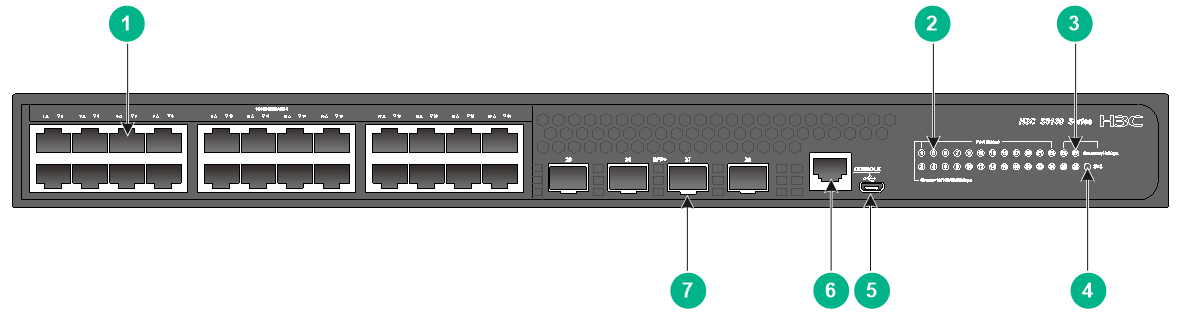
S5130S-10P-EI
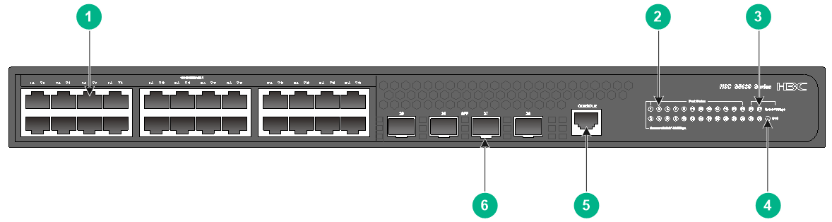
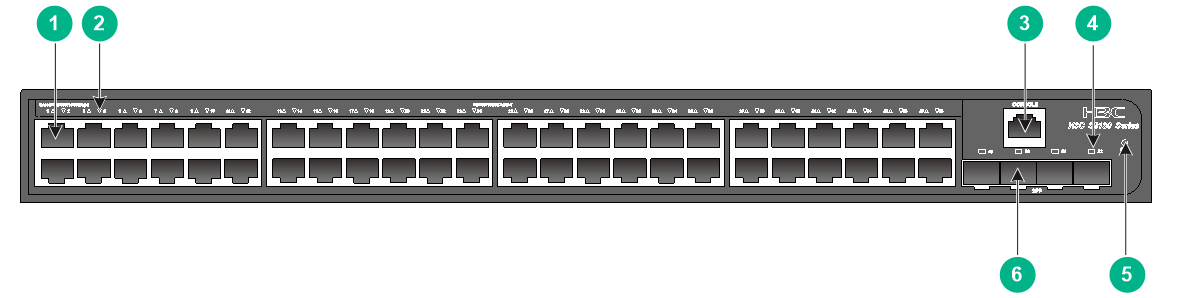
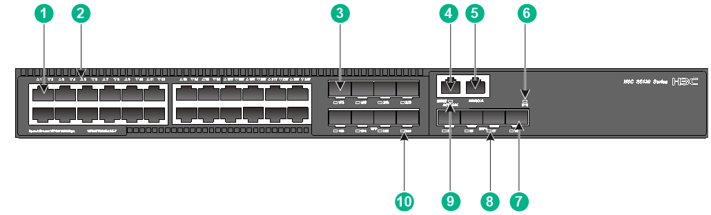
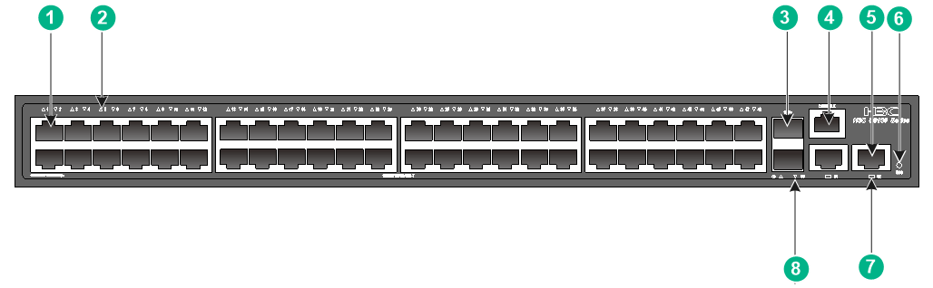
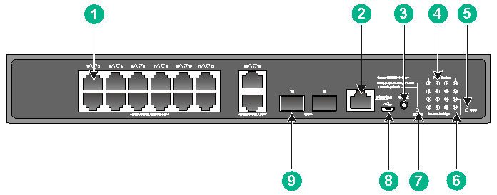
Figure2-1 Front panel
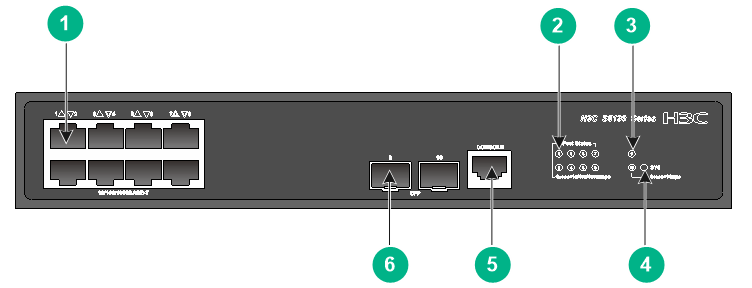
|
(1) 10/100/1000BASE-T autosensing Ethernet port |
|
|
(2) 10/100/1000BASE-T autosensing Ethernet port LED |
|
|
(3) SFP port LED |
(4) System status LED (SYS) |
|
(5) Console port (CONSOLE) |
(6) SFP port |
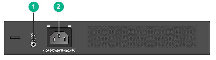
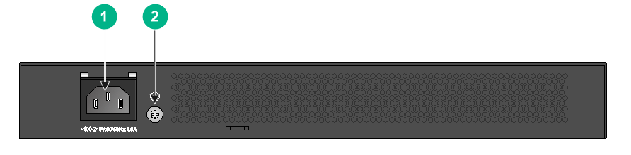
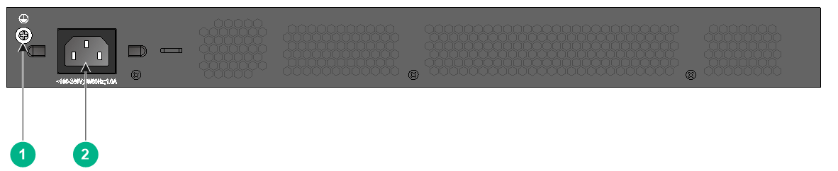
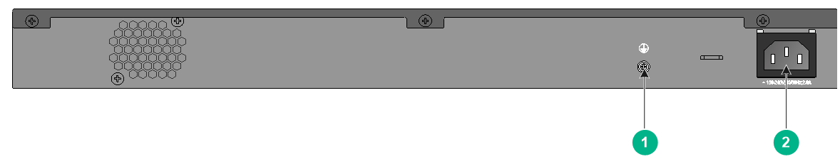
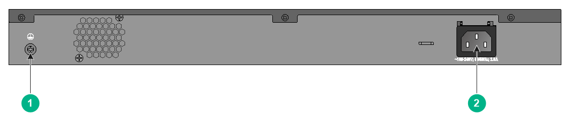
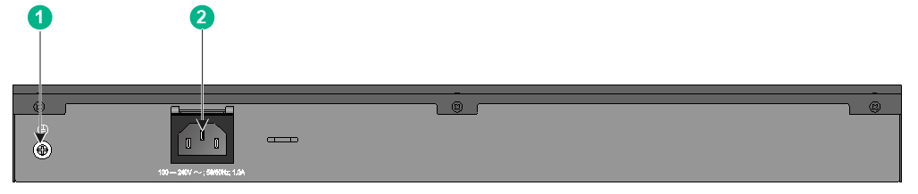
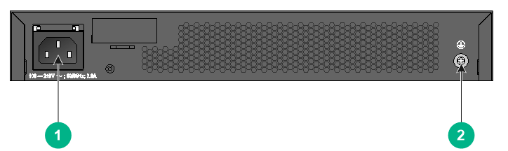
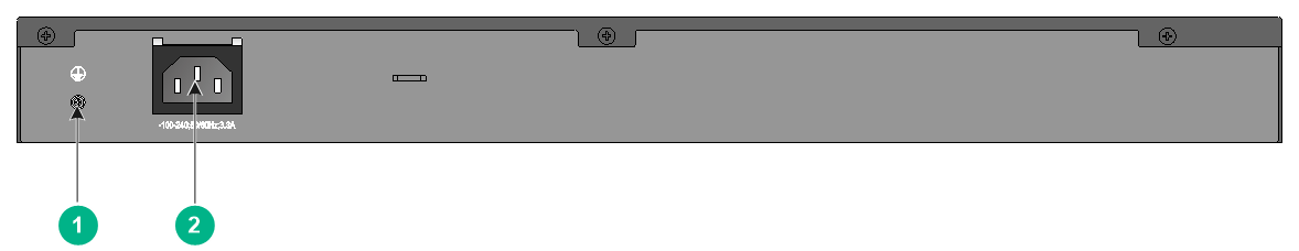
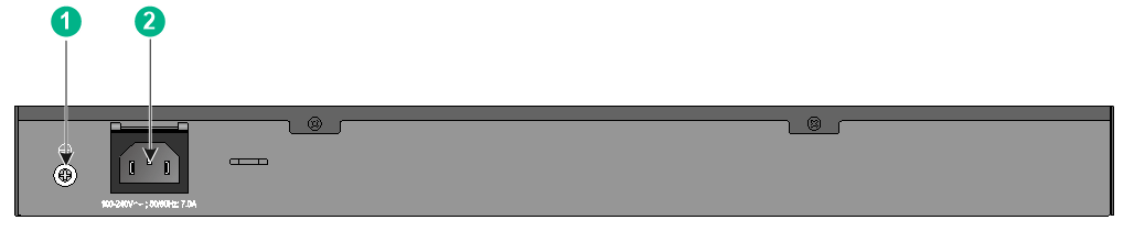
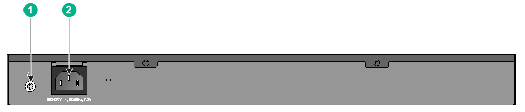
Figure2-2 Rear panel

|
(1) Grounding screw |
(2) AC-input power receptacle |
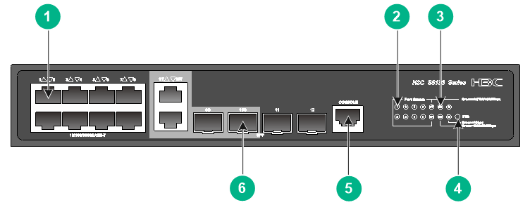
S5130S-12TP-EI
Figure2-3 Front panel
|
(1) 10/100/1000BASE-T autosensing Ethernet port |
|
|
(2) 10/100/1000BASE-T autosensing Ethernet port LED |
|
|
(3) SFP port LED |
(4) System status LED (SYS) |
|
(5) Console port (CONSOLE) |
(6) SFP port |
Figure2-4 Rear panel
|
(1) Grounding screw |
(2) AC-input power receptacle |
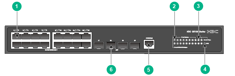
S5130S-20P-EI
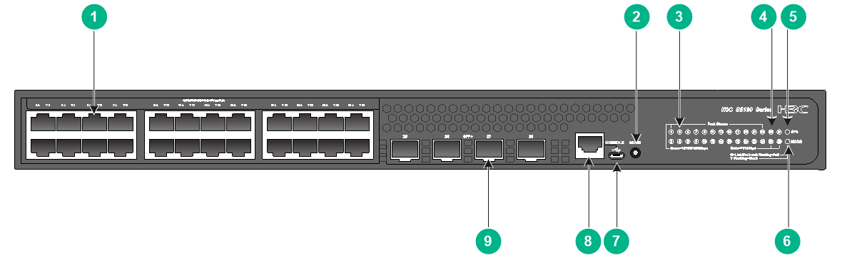
Figure2-5 Front panel
|
(1) 10/100/1000BASE-T autosensing Ethernet port |
|
|
(2) 10/100/1000BASE-T autosensing Ethernet port LED |
|
|
(3) SFP port LED |
(4) System status LED (SYS) |
|
(5) Console port (CONSOLE) |
(6) SFP port |
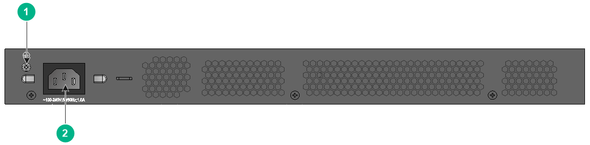
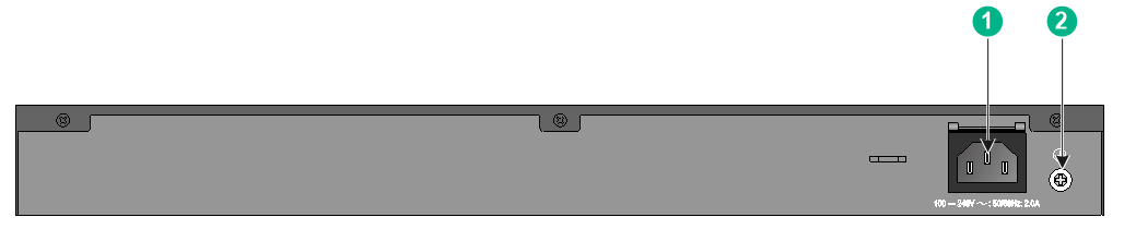
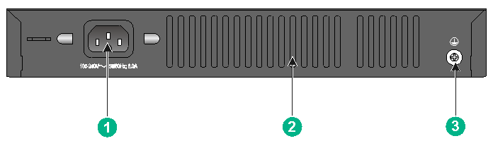
Figure2-6 Rear panel
|
(1) AC-input power receptacle |
(2) Grounding screw |
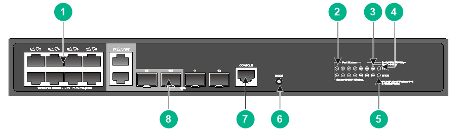
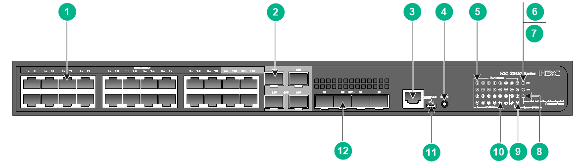
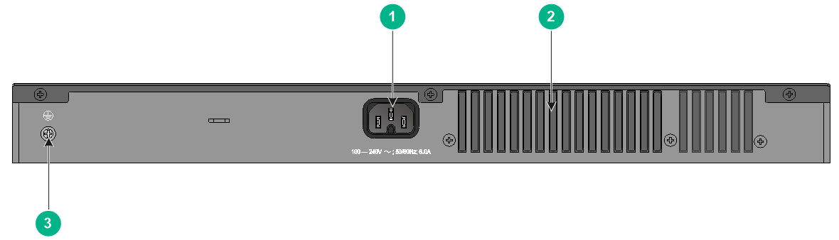
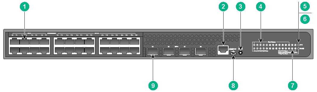
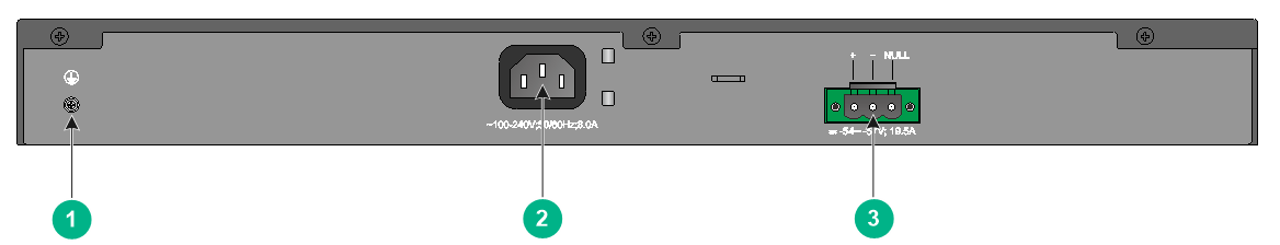
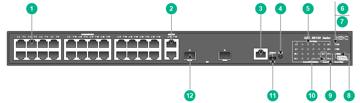
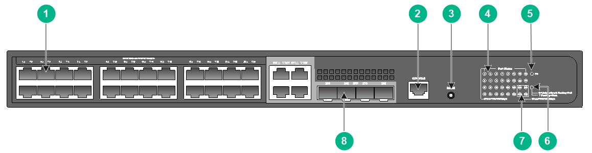
S5130S-28P-EI/S5130S-28P-EI-M
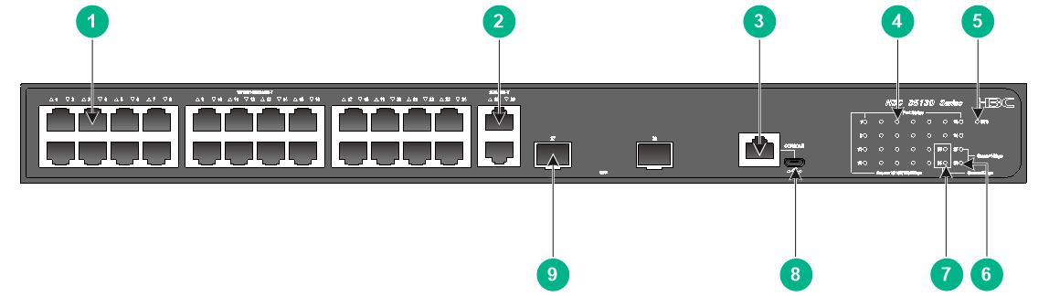
Figure2-7 Front panel
|
(1) 10/100/1000BASE-T autosensing Ethernet port |
|
|
(2) 10/100/1000BASE-T autosensing Ethernet port LED |
|
|
(3) SFP port LED |
(4) System status LED (SYS) |
|
(5) Console port (CONSOLE) |
(6) SFP port |
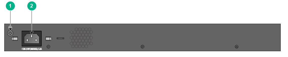
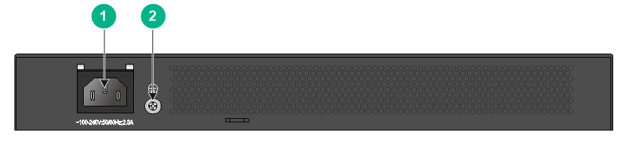
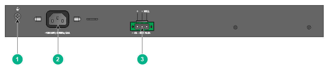
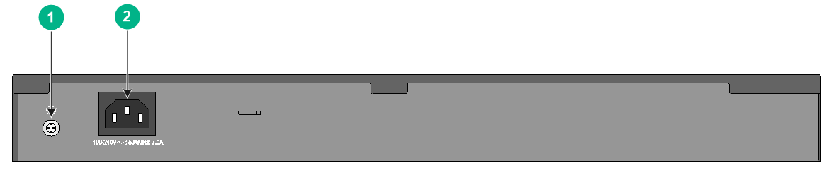
Figure2-8 Rear panel
|
(1) Grounding screw |
(2) AC-input power receptacle |
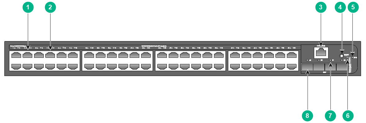
S5130S-28TP-EI
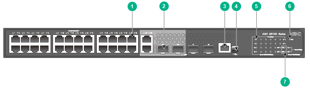
Figure2-9 Front panel
|
(1) 10/100/1000BASE-T autosensing Ethernet port |
(2) SFP port |
|
(3) Console port (CONSOLE) |
(4) Micro USB console port |
|
(5) 10/100/1000BASE-T autosensing Ethernet port LED |
(6) System status LED (SYS) |
|
(7) SFP port LED |
|
Figure2-10 Rear panel
|
(1) Grounding screw |
(2) AC-input power receptacle |
S5130S-52P-EI/S5130S-52P-EI-M
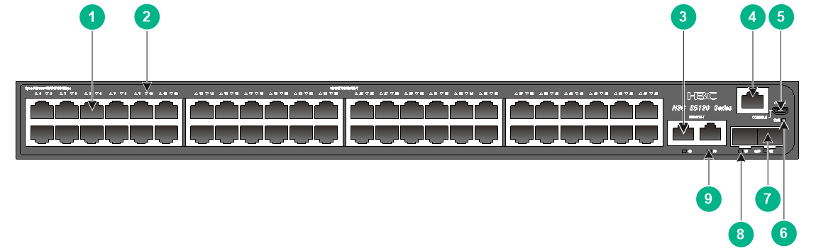
Figure2-11 Front panel
|
(1) 10/100/1000BASE-T autosensing Ethernet port |
|
|
(2) 10/100/1000BASE-T autosensing Ethernet port LED |
|
|
(3) Console port (CONSOLE) |
(4) SFP port LED |
|
(5) System status LED (SYS) |
(6) SFP port |
Figure2-12 Rear panel

|
(1) Grounding screw |
(2) AC-input power receptacle |
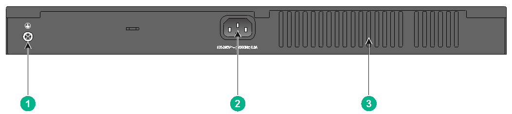
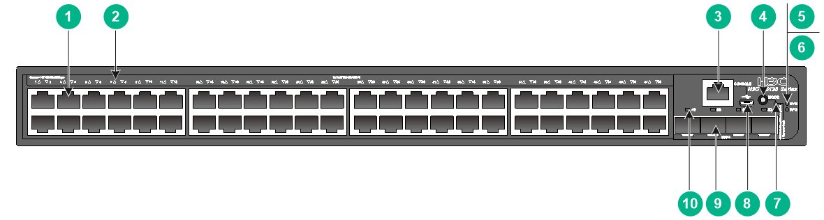
S5130S-52TP-EI
Figure2-13 Front panel
|
(1) 10/100/1000BASE-T autosensing Ethernet port |
|
|
(2) 10/100/1000BASE-T autosensing Ethernet port LED |
|
|
(3) Console port (CONSOLE) |
(4) Micro USB console port |
|
(5) System status LED (SYS) |
(6) SFP port LED |
|
(7) SFP port |
|
Figure2-14 Rear panel
|
(1) Grounding screw |
(2) AC-input power receptacle |
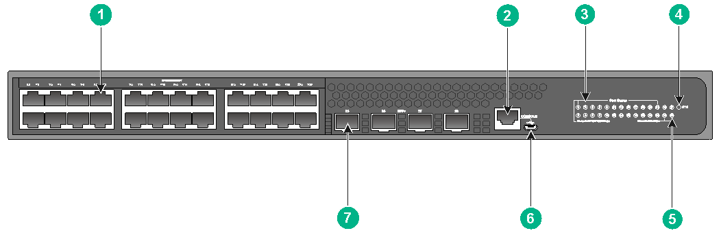
S5130S-28S-EI/S5130S-28S-EI-M
Figure2-15 Front panel
|
(1) 10/100/1000BASE-T autosensing Ethernet port |
|
|
(2) 10/100/1000BASE-T autosensing Ethernet port LED |
|
|
(3) SFP+ port LED |
(4) System status LED (SYS) |
|
(5) Micro USB console port |
(6) Console port (CONSOLE) |
|
(7) SFP+ port |
|
Figure2-16 Rear panel

|
(1) Grounding screw |
(2) AC-input power receptacle |
S5130S-28S-EI-DP
Figure2-17 Front panel
|
(1) 10/100/1000BASE-T autosensing Ethernet port |
(2) Console port (CONSOLE) |
|
(3) 10/100/1000BASE-T autosensing Ethernet port LED |
(4) System status LED (SYS) |
|
(5) SFP+ port LED |
(6) Micro USB console port |
|
(7) SFP+ port |
|
Figure2-18 Rear panel
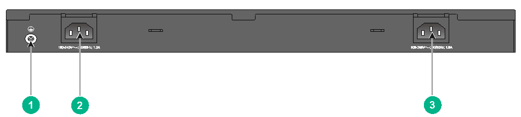
|
(1) Grounding screw |
(2) AC-input power receptacle 1 |
|
(3) AC-input power receptacle 2 |
|
The S5130S-28S-EI-DP switch has two AC-input power receptacles on the rear panel. You can use one AC power input, or two AC power inputs for 1+1 redundancy.
S5130S-52S-EI/S5130S-52S-EI-M
Figure2-19 Front panel
|
(1) 10/100/1000BASE-T autosensing Ethernet port |
|
|
(2) 10/100/1000BASE-T autosensing Ethernet port LED |
|
|
(3) Console port (CONSOLE) |
(4) Micro USB console port |
|
(5) SFP+ port LED |
(6) System status LED (SYS) |
|
(7) SFP+ port |
|
Figure2-20 Rear panel
|
(1) Grounding screw |
(2) AC-input power receptacle |
S5130S-28F-EI
Figure2-21 Front panel
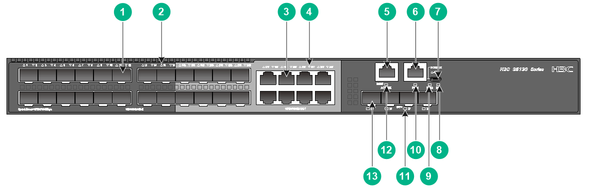
|
(1) SFP port |
(2) SFP port LED |
|
|
(3) 10/100/1000BASE-T autosensing Ethernet port |
||
|
(4) 10/100/1000BASE-T autosensing Ethernet port LED |
||
|
(5) Management Ethernet port |
(6) Console port (CONSOLE) |
|
|
(7) Micro USB console port |
(8) System status LED (SYS) |
|
|
(9) Power supply 2 status LED (PWR2) |
(10) Power supply 1 status LED (PWR1) |
|
|
(11) SFP+ port LED |
(12) Management Ethernet port status LED (ACT/LINK) |
|
|
(13) SFP+ port |
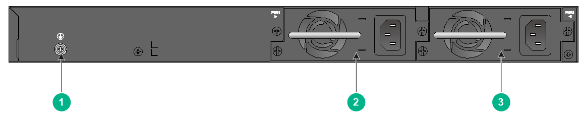
||
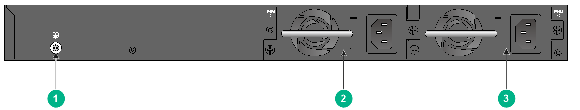
|
(1) Grounding screw |
(2) Power supply 1 (PWR1) |
|
(3) Power supply 2 (PWR2) |
|
The S5130S-28F-EI switch comes with power supply 1 empty and power supply slot 2 installed with a filler panel. You can install one or two power supplies for the switch as needed. In Figure2-22, two PSR150-A1 AC power supplies are installed.
S5130S-52F-EI
Figure2-23 Front panel
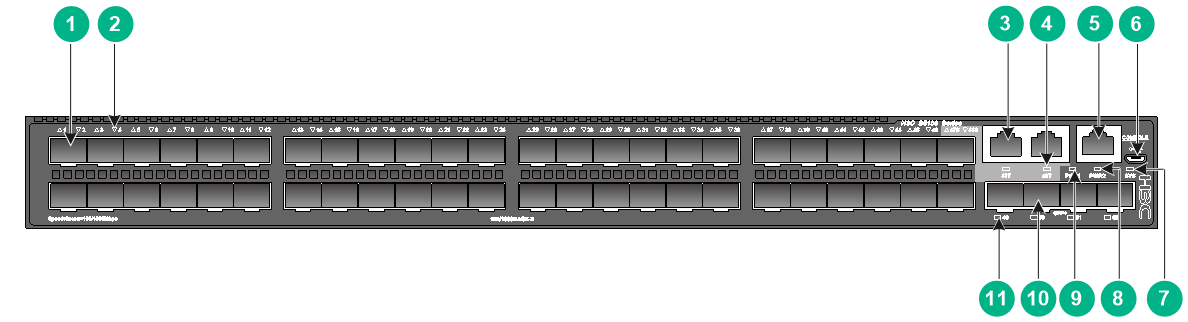
|
(1) SFP port |
(2) SFP port LED |
|
(3) 10/100/1000BASE-T autosensing Ethernet port |
|
|
(4) 10/100/1000BASE-T autosensing Ethernet port LED |
|
|
(5) Console port (CONSOLE) |
(6) Micro USB console port |
|
(7) System status LED (SYS) |
(8) Power supply 2 status LED (PWR2) |
|
(9) Power supply 1 status LED (PWR1) |
(10) SFP+ port |
|
(11) SFP+ port LED |
|
|
(1) Grounding screw |
(2) Power supply 1 (PWR1) |
|
(3) Power supply 2 (PWR2) |
|
The S5130S-52F-EI switch comes with power supply slot 1 empty and power supply slot 2 installed with a filler panel. You can install one or two power supplies for the switch as needed. In Figure2-24, two PSR150-A1 AC power supplies are installed.
S5130S-28MP-EI
Figure2-25 Front panel
|
(1) 10/100/1000BASE-T autosensing Ethernet port |
|
|
(2) 5G/2.5G/1000BASE-T autosensing Ethernet port (5GBASE-T) |
|
|
(3) Console port (CONSOLE) |
|
|
(4) 10/100/1000BASE-T autosensing Ethernet port LED |
|
|
(5) System status LED (SYS) |
(6) SFP port LED |
|
(7) 5G/2.5G/1000BASE-T autosensing Ethernet port LED |
|
|
(8) Micro USB console port |
(9) SFP port |
Figure2-26 Rear panel
|
(1) Grounding screw |
(2) AC-input power receptacle |
S5130S-52MP-EI
Figure2-27 Front panel
|
(1) 10/100/1000BASE-T autosensing Ethernet port |
|
|
(2) 10/100/1000BASE-T autosensing Ethernet port LED |
|
|
(3) 5G/2.5G/1000BASE-T autosensing Ethernet port (5GBASE-T) |
|
|
(4) Console port (CONSOLE) |
|
|
(5) Micro USB console port |
(6) System status LED (SYS) |
|
(7) SFP port |
(8) SFP port LED |
|
(9) 5G/2.5G/1000BASE-T autosensing Ethernet port LED |
|
Figure2-28 Rear panel
|
(1) Grounding screw |
(2) AC-input power receptacle |
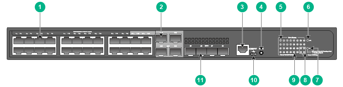
S5130S-28PS-EI
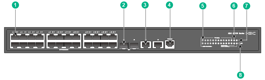
Figure2-29 Front panel
|
(1) 10/100/1000BASE-T autosensing Ethernet port |
|
|
(2) 10/100/1000BASE-T autosensing Ethernet port LED |
|
|
(3) SFP port |
(4) Management Ethernet port |
|
(5) Console port (CONSOLE) |
(6) System status LED (SYS) |
|
(7) SFP+ port |
(8) SFP+ port LED |
|
(9) Management Ethernet port status LED (ACT/LINK) |
|
|
(10) SFP port LED |
|
Figure2-30 Rear panel
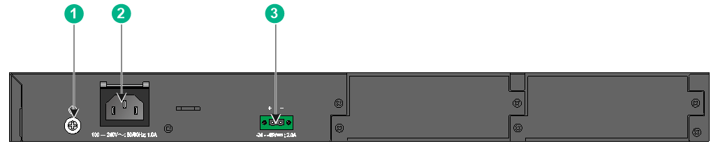
|
(1) Grounding screw |
(2) AC-input power receptacle |
|
(3) DC-input power receptacle |
|
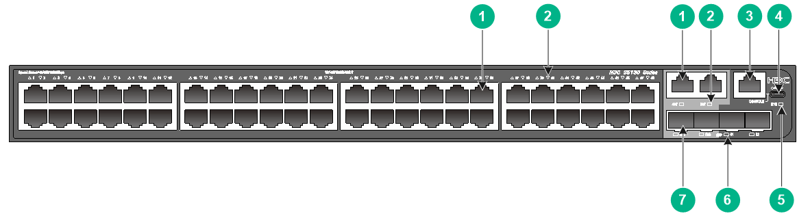
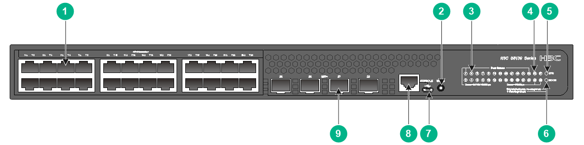
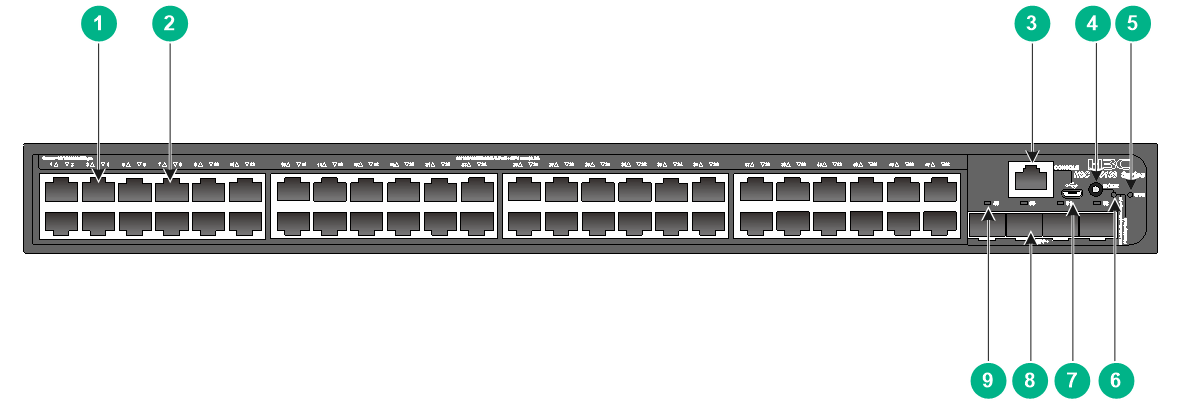
S5130S-28ST-EI
Figure2-31 Front panel
|
(1) 10/100/1000BASE-T autosensing Ethernet port |
(2) SFP+ port |
|
(3) 10/5/2.5/1GBASE-T autosensing Ethernet port |
(4) Console port (CONSOLE) |
|
(5) 10/100/1000BASE-T autosensing Ethernet port LED |
(6) SFP+ port LED |
|
(7) 10/5/2.5/1GBASE-T autosensing Ethernet port LED |
(8) System status LED (SYS) |
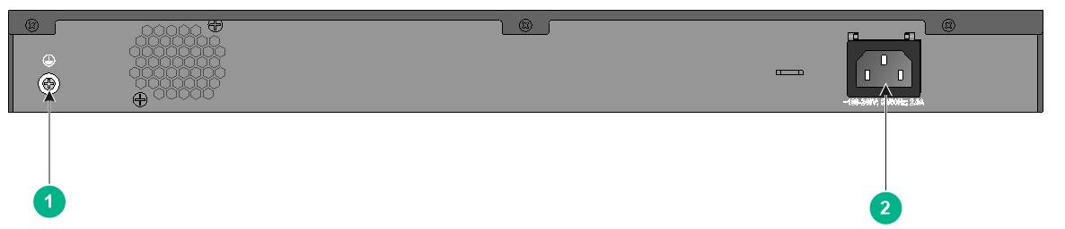
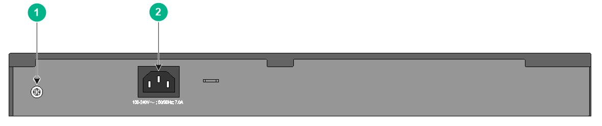
Figure2-32 Rear panel
|
(1) Grounding screw |
(2) AC-input power receptacle |
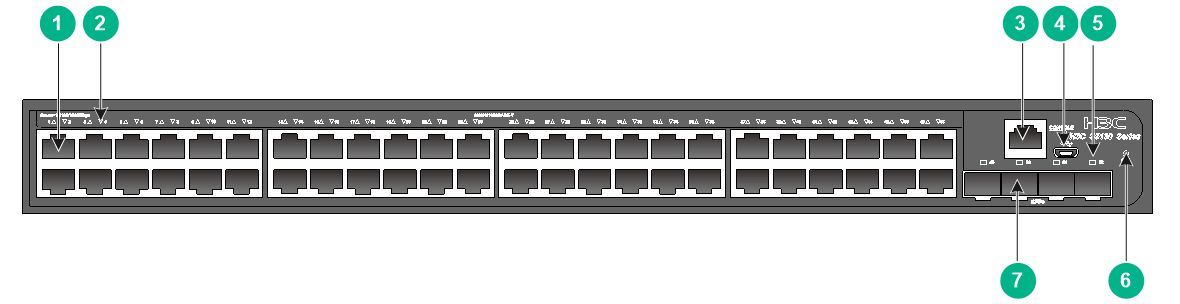
S5130S-52ST-EI
Figure2-33 Front panel
|
(1) 10/100/1000BASE-T autosensing Ethernet port |
|
|
(2) 10/100/1000BASE-T autosensing Ethernet port LED |
|
|
(3) SFP+ port |
(4) Console port (CONSOLE) |
|
(5) 10/5/2.5/1GBASE-T autosensing Ethernet port |
(6) System status LED (SYS) |
|
(7) 10/5/2.5/1GBASE-T autosensing Ethernet port LED |
(8) SFP+ port LED |
Figure2-34 Rear panel
|
(1) AC-input power receptacle |
(2) Grounding screw |
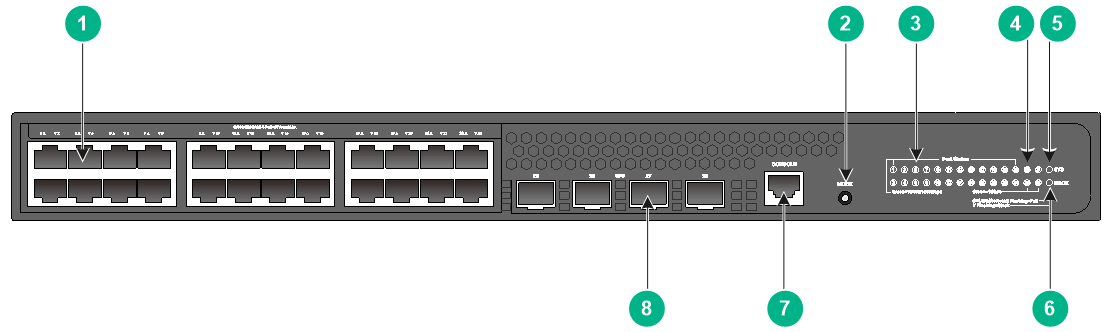
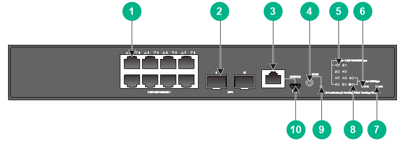
S5130S-10P-HPWR-EI
Figure2-35 Front panel
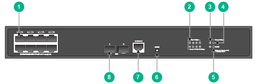
|
(1) 10/100/1000BASE-T autosensing Ethernet port |
|
|
(2) 10/100/1000BASE-T autosensing Ethernet port LED |
|
|
(3) SFP port LED |
(4) System status LED (SYS) |
|
(5) Mode LED (MODE) |
(6) Port LED mode switching button |
|
(7) Console port (CONSOLE) |
(8) SFP port |
Figure2-36 Rear panel

|
(1) AC-input power receptacle |
(2) Grounding screw |
S5130S-12TP-HPWR-EI
Figure2-37 Front panel
|
(1) 10/100/1000BASE-T autosensing Ethernet port |
|
|
(2) 10/100/1000BASE-T autosensing Ethernet port LED |
|
|
(3) SFP port LED |
(4) System status LED (SYS) |
|
(5) Mode LED (MODE) |
(6) Port LED mode switching button |
|
(7) Console port (CONSOLE) |
(8) SFP port |
Figure2-38 Rear panel
|
(1) AC-input power receptacle |
(2) Grounding screw |
S5130S-20P-PWR-EI
Figure2-39 Front panel
|
(1) 10/100/1000BASE-T autosensing Ethernet port |
|
|
(2) 10/100/1000BASE-T autosensing Ethernet port LED |
|
|
(3) SFP port LED |
(4) System status LED (SYS) |
|
(5) Mode LED (MODE) |
(6) Port LED mode switching button |
|
(7) Console port (CONSOLE) |
(8) SFP port |
Figure2-40 Rear panel
|
(1) AC-input power receptacle |
(2) Grounding screw |
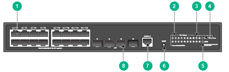
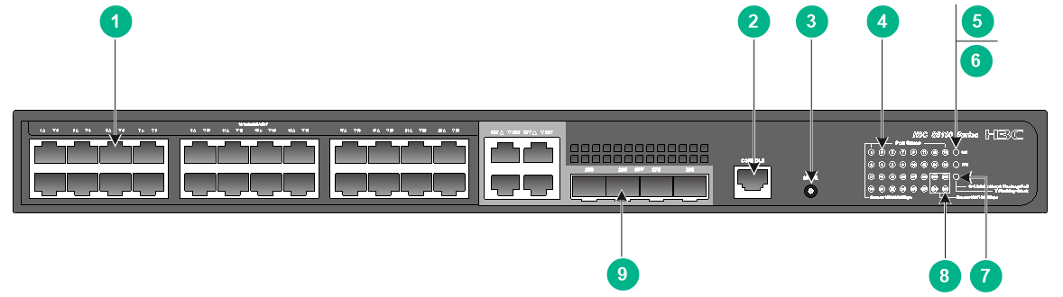
S5130S-28P-PWR-EI
Figure2-41 Front panel
|
(1) 10/100/1000BASE-T autosensing Ethernet port |
(2) Port LED mode switching button |
|
(3) 10/100/1000BASE-T autosensing Ethernet port LED |
(4) SFP port LED |
|
(5) System status LED (SYS) |
(6) Mode LED (MODE) |
|
(7) Console port (CONSOLE) |
(8) SFP port |
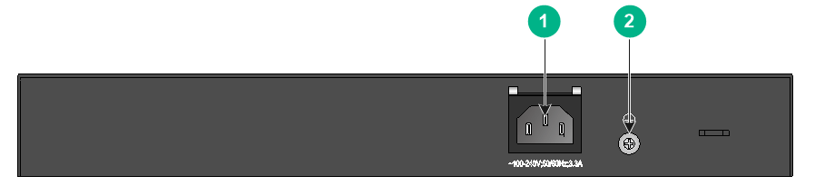
Figure2-42 Rear panel (product code LS-5130S-28P-PWR-EI)

|
(1) Grounding screw |
(2) AC-input power receptacle |
Figure2-43 Rear panel (product code LS-5130S-28P-PWR-EI-H1)

|
(1) Grounding screw |
(2) AC-input power receptacle |
S5130S-28P-HPWR-EI
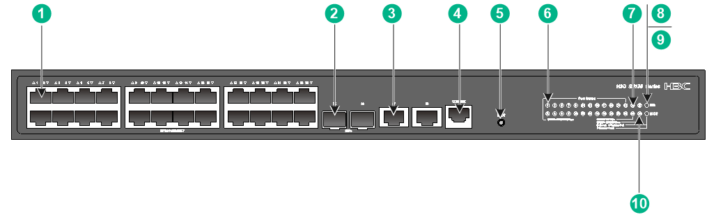
Figure2-44 Front panel
|
(1) 10/100/1000BASE-T autosensing Ethernet port |
(2) Console port (CONSOLE) |
|
(3) Port LED mode switching button |
|
|
(4) 10/100/1000BASE-T autosensing Ethernet port LED |
|
|
(5) System status LED (SYS) |
(6) RPS status LED (RPS) |
|
(7) Mode LED (MODE) |
(8) SFP port LED |
|
(9) SFP port |
|
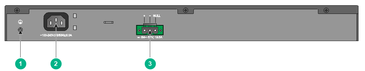
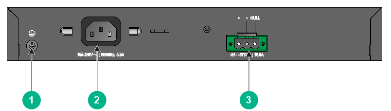
Figure2-45 Rear panel

|
(1) Grounding screw |
(2) AC-input power receptacle |
|
(3) DC-input power receptacle |
|
S5130S-52P-PWR-EI
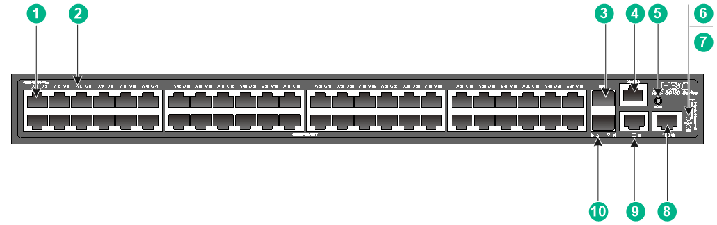
Figure2-46 Front panel
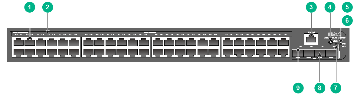
|
(1) 10/100/1000BASE-T autosensing Ethernet port |
|
|
(2) 10/100/1000BASE-T autosensing Ethernet port LED |
|
|
(3) Console port (CONSOLE) |
(4) Port LED mode switching button |
|
(5) System status LED (SYS) |
(6) RPS status LED (RPS) |
|
(7) Mode LED (MODE) |
(8) SFP port |
|
(9) SFP port LED |
|
Figure2-47 Rear panel

|
(1) Grounding screw |
(2) AC-input power receptacle |
|
(3) DC-input power receptacle |
|
S5130S-16S-PWR-EI
Figure2-48 Front panel
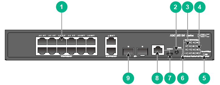
|
(1) 10/100/1000BASE-T autosensing Ethernet port |
(2) Port LED mode switching button |
|
(3) 10/100/1000BASE-T autosensing Ethernet port LED |
(4) SFP+ port LED |
|
(5) System status LED (SYS) |
(6) Mode LED (MODE) |
|
(7) Micro USB console port |
(8) Console port (CONSOLE) |
|
(9) SFP+ port |
|
Figure2-49 Rear panel
|
(1) AC-input power receptacle |
(2) Grounding screw |
S5130S-16S-UPWR-EI-Q
Figure2-50 Front panel
|
(1) 10/100/1000BASE-T autosensing Ethernet port |
(2) Console port (CONSOLE) |
|
(3) Port LED mode switching button |
|
|
(4) 10/100/1000BASE-T autosensing Ethernet port LED |
|
|
(5) System status LED (SYS) |
(6) SFP+ port LED |
|
(7) Mode LED (MODE) |
(8) Micro USB console port |
|
(9) SFP+ port |
|
Figure2-51 Rear panel
|
(1) AC-input power receptacle |
(2) Heat sink |
|
(3) Grounding screw |
|
S5130S-28S-PWR-EI
Figure2-52 Front panel
|
(1) 10/100/1000BASE-T autosensing Ethernet port |
(2) Port LED mode switching button |
|
(3) 10/100/1000BASE-T autosensing Ethernet port LED |
(4) SFP+ port LED |
|
(5) System status LED (SYS) |
(6) Mode LED (MODE) |
|
(7) Micro USB console port |
(8) Console port (CONSOLE) |
|
(9) SFP+ port |
|
Figure2-53 Rear panel (product code LS-5130S-28S-PWR-EI)
|
(1) Grounding screw |
(2) AC-input power receptacle |
Figure2-54 Rear panel (product code LS-5130S-28S-PWR-EI-H1)

|
(1) Grounding screw |
(2) AC-input power receptacle |
S5130S-28S-HPWR-EI
Figure2-55 Front panel
|
(1) 10/100/1000BASE-T autosensing Ethernet port |
(2) SFP port |
|
(3) Console port (CONSOLE) |
(4) Port LED mode switching button |
|
(5) 10/100/1000BASE-T autosensing Ethernet port LED |
(6) System status LED (SYS) |
|
(7) RPS status LED (RPS) |
(8) Mode LED (MODE) |
|
(9) SFP+ port LED |
(10) SFP port LED |
|
(11) Micro USB console port |
(12) SFP+ port |
Figure2-56 Rear panel
|
(1) Grounding screw |
(2) AC-input power receptacle |
|
(3) DC-input power receptacle |
|
S5130S-28S-HPWR-EI-Q
Figure2-57 Front panel
|
(1) 10/100/1000BASE-T autosensing Ethernet port |
(2) Port LED mode switching button |
|
(3) 10/100/1000BASE-T autosensing Ethernet port LED |
(4) SFP+ port LED |
|
(5) System status LED (SYS) |
(6) Mode LED (MODE) |
|
(7) Micro USB console port |
(8) Console port (CONSOLE) |
|
(9) SFP+ port |
|
Figure2-58 Rear panel
|
(1) AC-input power receptacle |
(2) Heat sink |
|
(3) Grounding screw |
|
S5130S-28S-UPWR-EI-Q
Figure2-59 Front panel
|
(1) 10/100/1000BASE-T autosensing Ethernet port |
(2) Console port (CONSOLE) |
|
(3) Port LED mode switching button |
|
|
(4) 10/100/1000BASE-T autosensing Ethernet port LED |
|
|
(5) System status LED (SYS) |
(6) Mode LED (MODE) |
|
(7) SFP+ port LED |
(8) Micro USB console port |
|
(9) SFP+ port |
|
Figure2-60 Rear panel
|
(1) Grounding screw |
(2) AC-input power receptacle |
|
(3) Heat sink |
|
S5130S-52S-PWR-EI
Figure2-61 Front panel
|
(1) 10/100/1000BASE-T autosensing Ethernet port |
|
|
(2) 10/100/1000BASE-T autosensing Ethernet port LED |
|
|
(3) Console port (CONSOLE) |
(4) Port LED mode switching button |
|
(5) System status LED (SYS) |
(6) RPS status LED (RPS) |
|
(7) Mode LED (MODE) |
(8) Micro USB console port |
|
(9) SFP+ port |
(10) SFP+ port LED |
Figure2-62 Rear panel
|
(1) Grounding screw |
(2) AC-input power receptacle |
|
(3) DC-input power receptacle |
|
S5130S-28MP-HPWR-EI
Figure2-63 Front panel
|
(1) 10/100/1000BASE-T autosensing Ethernet port |
||
|
(2) 5G/2.5G/1000BASE-T autosensing Ethernet port (5GBASE-T) |
||
|
(3) Console port (CONSOLE) |
(4) Port LED mode switching button |
|
|
(5) 10/100/1000BASE-T autosensing Ethernet port LED |
||
|
(6) System status LED (SYS) |
(7) RPS status LED (RPS) |
|
|
(8) Mode LED (MODE) |
(9) SFP port LED |
|
|
(10) 5G/2.5G/1000BASE-T autosensing Ethernet port LED |
||
|
(11) Micro USB console port |
(12) SFP port |
|
Figure2-64 Rear panel
|
(1) Grounding screw |
(2) AC-input power receptacle |
|
(3) DC-input power receptacle |
|
S5130S-10MS-UPWR-EI
Figure2-65 Front panel
|
(1) 2.5G/1000/100BASE-T autosensing Ethernet port |
(2) SFP+ port |
|
(3) Console port (CONSOLE) |
(4) Port LED mode switching button |
|
(5) 2.5G/1000/100BASE-T autosensing Ethernet port LED |
(6) System status LED (SYS) |
|
(7) RPS status LED (RPS) |
(8) SFP+ port LED |
|
(9) Mode LED (MODE) |
(10) Micro USB console port |
Figure2-66 Rear panel
|
(1) Grounding screw |
(2) AC-input power receptacle |
|
(3) DC-input power receptacle |
|
S5130S-28ST-PWR-EI
Figure2-67 Front panel
|
(1) 10/100/1000BASE-T autosensing Ethernet port |
(2) SFP+ port |
|
(3) 10/5/2.5/1GBASE-T autosensing Ethernet port |
(4) Console port (CONSOLE) |
|
(5) Port LED mode switching button |
|
|
(6) 10/100/1000BASE-T autosensing Ethernet port LED |
|
|
(7) SFP+ port LED |
(8) System status LED (SYS) |
|
(9) Mode LED (MODE) |
|
|
(10) 10/5/2.5/1GBASE-T autosensing Ethernet port LED |
|
Figure2-68 Rear panel
|
(1) Grounding screw |
(2) AC-input power receptacle |
S5130S-52ST-PWR-EI
Figure2-69 Front panel
|
(1) 10/100/1000BASE-T autosensing Ethernet port |
|
|
(2) 10/100/1000BASE-T autosensing Ethernet port LED |
|
|
(3) SFP+ port |
(4) Console port (CONSOLE) |
|
(5) Port LED mode switching button |
(6) Mode LED (MODE) |
|
(7) System status LED (SYS) |
|
|
(8) 10/5/2.5/1GBASE-T autosensing Ethernet port |
|
|
(9) 10/5/2.5/1GBASE-T autosensing Ethernet port LED |
(10) SFP+ port LED |
Figure2-70 Rear panel
|
(1) AC-input power receptacle |
(2) Grounding screw |
S5130S-52P-PWR-EI-AC
Figure2-71 Front panel
|
(1) 10/100/1000BASE-T autosensing Ethernet port |
|
|
(2) 10/100/1000BASE-T autosensing Ethernet port LED |
|
|
(3) Console port (CONSOLE) |
(4) Port LED mode switching button |
|
(5) System status LED (SYS) |
(6) Mode LED (MODE) |
|
(7) SFP port LED |
(8) SFP port |
Figure2-72 Rear panel

|
(1) Grounding screw |
(2) AC-input power receptacle |
S5130S-52S-PWR-EI-AC
Figure2-73 Front panel
|
(1) 10/100/1000BASE-T autosensing Ethernet port |
|
|
(2) 10/100/1000BASE-T autosensing Ethernet port LED |
|
|
(3) Console port (CONSOLE) |
(4) Port LED mode switching button |
|
(5) System status LED (SYS) |
(6) Mode LED (MODE) |
|
(7) Micro USB console port |
(8) SFP+ port |
|
(9) SFP+ port LED |
|
Figure2-74 Rear panel
|
(1) Grounding screw |
(2) AC-input power receptacle |
S5130S-28P-HPWR-EI-AC
Figure2-75 Front panel
|
(1) 10/100/1000BASE-T autosensing Ethernet port |
(2) Console port (CONSOLE) |
|
(3) Port LED mode switching button |
(4) 10/100/1000BASE-T autosensing Ethernet port LED |
|
(5) System status LED (SYS) |
(6) Mode LED (MODE) |
|
(7) SFP port LED |
(8) SFP port |
Figure2-76 Rear panel
|
(1) Grounding screw |
(2) AC-input power receptacle |
S5130S-28S-HPWR-EI-AC
Figure2-77 Front panel
|
(1) 10/100/1000BASE-T autosensing Ethernet port |
(2) SFP port |
|
(3) Console port (CONSOLE) |
(4) Port LED mode switching button |
|
(5) 10/100/1000BASE-T autosensing Ethernet port LED |
|
|
(6) System status LED (SYS) |
(7) Mode LED (MODE) |
|
(8) SFP+ port LED |
(9) SFP port LED |
|
(10) Micro USB console port |
(11) SFP+ port |
Figure2-78 Rear panel

|
(1) Grounding screw |
(2) AC-input power receptacle |
3 Removable components
|
|
WARNING! · You can replace one of the two power supplies operating in 1+1 redundancy on the S5130S-28F-EI and S5130S-52F-EI switches. To avoid device damage and bodily injury, make sure the power supply is powered off before removing it. · To install AC power supplies on an S5130S-28F-EI or S5130S-52F-EI switch, choose the CA-70A12 or PSR75-12A power supplies as a best practice. |
The S5130S-28F-EI and S5130S-52F-EI switches each provide two power supply slots. One power supply can meet the power requirement of the switch. You can install two power supplies on the switch for 1+1 redundancy. Table3-1 describes the power supplies available for the S5130S-52F-EI switch.
Table3-1 Power supplies available for the S5130S-52F-EI switch
|
Power supply model |
Item |
Specification |
Remarks |
|
CA-70A12 |
Rated input voltage |
100 VAC to 240 VAC @ 50 Hz or 60 Hz |
H3C CA-70A12 Power Supply User Manual |
|
Max input voltage |
90 VAC to 290 VAC @ 47 Hz to 63 Hz |
||
|
Max output power |
75 W |
||
|
PSR75-12A |
Rated input voltage |
AC: 100 VAC to 240 VAC @ 50 Hz or 60 Hz DC: 240 VDC |
For more information about the power supply, see H3C PSR75-12A Power Module User Manual. |
|
Max input voltage |
AC: 90 VAC to 290 VAC @ 47 Hz to 63 Hz DC: 180 VDC to 320 VDC |
||
|
Max output power |
75 W |
||
|
PSR150-A1 |
Rated input voltage |
100 VAC to 240 VAC @ 50 Hz or 60 Hz |
For more information about the power supplies, see H3C PSR150-A & PSR150-D Series Power Supplies User Manual. |
|
Max input voltage |
90 VAC to 264 VAC @ 47 Hz to 63 Hz |
||
|
Max output power |
150 W |
||
|
PSR150-D1 |
Rated input voltage |
–48 VDC to –60 VDC |
|
|
Max input voltage |
–36 VDC to –72 VDC |
||
|
Max output power |
150 W |
4 Ports and LEDs
Ports
Console port
Table4-1 Console port specifications
|
Item |
Serial console port |
Micro USB console port |
|
Connector type |
RJ-45 |
Micro USB Type B |
|
Compliant standard |
EIA/TIA-232 |
USB 2.0 |
|
Transmission baud rate |
9600 bps (default) to 115200 bps |
|
|
Services |
· Provides connection to an ASCII terminal. · Provides connection to the serial port of a local PC running terminal emulation program. |
· Provides connection to an ASCII terminal. · Provides connection to the USB port of a local PC running terminal emulation program. |
|
Available switch models |
All switches |
· S5130S-28TP-EI · S5130S-52TP-EI · S5130S-16S-PWR-EI · S5130S-28S-EI · S5130S-28S-EI-M · S5130S-28S-EI-DP · S5130S-52S-EI · S5130S-52S-EI-M · S5130S-28S-PWR-EI · S5130S-16S-UPWR-EI-Q · S5130S-28S-UPWR-EI-Q · S5130S-28S-HPWR-EI · S5130S-28S-HPWR-EI-Q · S5130S-52S-PWR-EI · S5130S-52S-PWR-EI-AC · S5130S-28F-EI · S5130S-52F-EI · S5130S-10MS-UPWR-EI · S5130S-28MP-EI · S5130S-28MP-HPWR-EI · S5130S-52MP-EI |
|
Restrictions and guidelines |
You cannot use the serial console port and micro USB console port at the same time. If you connect both ports at the same time, only the micro USB console port takes effect. |
|
Management Ethernet port
The S5130S-28F-EI and S5130S-28PS-EI switches each have one management Ethernet port. You can connect the port to a local PC for software loading and debugging or to a remote management station for remote management.
Table4-2 Management Ethernet port specifications
|
Item |
Specification |
|
Connector type |
RJ-45 |
|
Transmission rate, duplex mode, and auto MDI/MDI-X |
· 10 Mbps, half/full duplex · 100 Mbps, half/full duplex · MDI/MDI-X autosensing |
|
Max transmission distance |
100 m (328.08 ft) |
|
Transmission medium |
Category-5 (or above) twisted pair cable |
|
Compatible standards |
· IEEE 802.3i · IEEE 802.3u · IEEE 802.3ab |
|
Functions and services |
Software upgrade and network management. |
10/100/1000BASE-T autosensing Ethernet port
Table4-3 10/100/1000BASE-T autosensing Ethernet port specifications
|
Item |
Specification |
|
Connector type |
RJ-45 |
|
Transmission rate, duplex mode, and auto MDI/MDI-X |
· 10 Mbps, half/full duplex · 100 Mbps, half/full duplex · 1000 Mbps, full duplex · MDI/MDI-X autosensing |
|
Max transmission distance |
100 m (328.08 ft) |
|
Transmission medium |
Category-5 (or above) twisted pair cable |
|
Compatible standards |
· IEEE 802.3i · IEEE 802.3u · IEEE 802.3ab |
5G/2.5G/1000BASE-T autosensing Ethernet port
The S5130S-28MP-EI, S5130S-28MP-HPWR-EI, and S5130S-52MP-EI switches provide 5G/2.5G/1000BASE-T autosensing Ethernet ports.
Table4-4 5G/2.5G/1000BASE-T autosensing Ethernet port specifications
|
Item |
Specification |
|
Connector type |
RJ-45 |
|
Transmission rate, duplex mode, and auto MDI/MDI-X |
· 1 Gbps, full duplex · 2.5 Gbps, full duplex · 5 Gbps, full duplex · MDI/MDI-X autosensing |
|
Max transmission distance |
· 5G mode: 100 m (328.08 ft) over Category-5e or above twisted pair · 2.5G mode: 200 m (656.17 ft) over Category-5e or above twisted pair · 1G mode: 200 m (656.17 ft) over Category-5e or above twisted pair |
|
Transmission medium |
Category-5e (or above) twisted pair cable |
|
Compatible standards |
· IEEE 802.3ab · IEEE 802.3an |
2.5G/1000/100BASE-T autosensing Ethernet port
The S5130S-10MS-UPWR-EI switch provides 2.5G/1000/100BASE-T autosensing Ethernet ports.
Table4-5 2.5G/1000/100BASE-T autosensing Ethernet port specifications
|
Item |
Specification |
|
Connector type |
RJ-45 |
|
Transmission rate, duplex mode, and auto MDI/MDI-X |
· 2.5 Gbps, full duplex · 1 Gbps, full duplex · 100 Mbps, full duplex · MDI/MDI-X autosensing |
|
Max transmission distance |
· 2.5G mode: 200 m (656.17 ft) over Category-5e or above twisted pair · 1G mode: 200 m (656.17 ft) over Category-5e or above twisted pair · 100M mode: 200 m (656.17 ft) over Category-5e or above twisted pair |
|
Transmission medium |
Category-5e (or above) twisted pair cable |
|
Compatible standards |
· IEEE 802.3ab · IEEE 802.3an |
10/5/2.5/1GBASE-T autosensing Ethernet port
The S5130S-28ST-EI, S5130S-52ST-EI, S5130S-28ST-PWR-EI, and S5130S-52ST-PWR-EI switches provide 10/5/2.5/1GBASE-T autosensing Ethernet ports.
Table4-6 10/5/2.5/1GBASE-T autosensing Ethernet port specifications
|
Item |
Specification |
|
Connector type |
RJ-45 |
|
Transmission rate, duplex mode, and auto MDI/MDI-X |
· 10 Gbps, full duplex · 5 Gbps, full duplex · 2.5 Gbps, full duplex · 1 Gbps, full duplex · MDI/MDI-X autosensing |
|
Max transmission distance |
· 10G mode: ¡ 100 m (328.08 ft) over Category-6 shielded twisted pair or above twisted pair ¡ 60 m (196.85 ft) over Category-5e twisted pair or Category-6 unshielded twisted pair · 5G mode: 100 m (328.08 ft) over Category-5e or above twisted pair · 2.5G mode: 200 m (656.17 ft) over Category-5e or above twisted pair · 1G mode: 200 m (656.17 ft) over Category-5e or above twisted pair |
|
Transmission medium |
Category-6 (or above) twisted pair cable |
|
Compatible standards |
· IEEE 802.3ab · IEEE 802.3an |
SFP port
Some S5130S-EI switch models provide SFP ports. Table4-7 describes the SFP port support for the SFP transceiver modules and cables.
Table4-7 SFP port support for SFP transceiver modules and cables
|
Model |
SFP port support for SFP transceiver modules and cables |
Restrictions |
|
S5130S-28S-EI S5130S-28ST-EI S5130S-28S-EI-M S5130S-28S-EI-DP S5130S-52ST-EI S5130S-52S-EI S5130S-52S-EI-M S5130S-16S-PWR-EI S5130S-28S-PWR-EI S5130S-28ST-PWR-EI S5130S-52S-PWR-EI S5130S-52S-PWR-EI-AC S5130S-52ST-PWR-EI S5130S-16S-UPWR-EI-Q S5130S-28S-HPWR-EI-Q S5130S-28S-UPWR-EI-Q S5130S-10MS-UPWR-EI |
No SFP ports |
N/A |
|
S5130S-10P-EI S5130S-20P-EI S5130S-28P-EI S5130S-28P-EI-M S5130S-28MP-EI S5130S-52MP-EI S5130S-10P-HPWR-EI S5130S-28MP-HPWR-EI |
GE SFP transceiver module and cables in Table4-8 |
To use transceiver modules with a maximum transmission distance greater than or equal to 80 km (49.71 miles), make sure the ambient temperature does not exceed 40°C (104°F). |
|
S5130S-52P-EI S5130S-52P-EI-M S5130S-20P-PWR-EI S5130S-28P-PWR-EI S5130S-52P-PWR-EI S5130S-52P-PWR-EI-AC |
N/A |
|
|
S5130S-12TP-EI S5130S-12TP-HPWR-EI |
· SFP ports 9 and 10: GE SFP transceiver module and cables in Table4-8 and FE SFP transceiver modules in Table4-9 · SFP ports 11 and 12: GE SFP transceiver module and cables in Table4-8 |
To use GE transceiver modules with a maximum transmission distance greater than or equal to 80 km (49.71 miles), make sure the ambient temperature does not exceed 40°C (104°F). |
|
S5130S-28TP-EI |
· SFP ports 25 and 26: GE SFP transceiver module and cables in Table4-8 and FE SFP transceiver modules in Table4-9 · SFP ports 27 and 28: GE SFP transceiver module and cables in Table4-8 |
To use transceiver modules with a maximum transmission distance greater than or equal to 80 km (49.71 miles), make sure the ambient temperature does not exceed 40°C (104°F). |
|
S5130S-52TP-EI |
· SFP ports 49 and 50: GE SFP transceiver module and cables in Table4-8 and FE SFP transceiver modules in Table4-9 · SFP ports 51 and 52: GE SFP transceiver module and cables in Table4-8 |
N/A |
|
S5130S-28PS-EI S5130S-28P-HPWR-EI S5130S-28S-HPWR-EI S5130S-28P-HPWR-EI-AC S5130S-28S-HPWR-EI-AC |
GE SFP transceiver modules and cables in Table4-8 and FE SFP transceiver modules in Table4-9 |
N/A |
|
S5130S-28F-EI S5130S-52F-EI |
GE SFP transceiver modules and cables in Table4-8 and FE SFP transceiver modules in Table4-9 |
Make sure the ambient temperature does not exceed 40°C (104°F) when the following conditions are met: · The switch uses one or two PSR75-12A for power supply. · The switch uses transceiver modules with a maximum transmission distance greater than or equal to 80 km (49.71 miles) |
Table4-8 GE SFP transceiver modules and cables
|
GE SFP transceiver module/cable |
Central wavelength |
Connector |
Cable specifications |
Modal bandwidth (MHz*km) |
Max transmission distance |
|
Copper SFP transceiver module |
|||||
|
SFP-GE-T |
N/A |
RJ-45 |
Twisted pair cable |
N/A |
100 m (328.09 ft) |
|
SFP-GE-T-D |
N/A |
RJ-45 |
Twisted pair cable |
N/A |
100 m (328.09 ft) |
|
Fiber SFP transceiver module |
|||||
|
SFP-GE-SX-MM850-A |
850 nm |
LC |
50/125 µm multi-mode optical fiber |
500 |
550 m (1804.46 ft) |
|
400 |
500 m (1640.42 ft) |
||||
|
62.5/125 µm multi-mode optical fiber |
200 |
275 m (902.23 ft) |
|||
|
160 |
220 m (721.78 ft) |
||||
|
SFP-GE-SX-MM850-D |
850 nm |
LC |
50/125 µm multi-mode optical fiber |
500 |
550 m (1804.46 ft) |
|
400 |
500 m (1640.42 ft) |
||||
|
62.5/125 µm multi-mode optical fiber |
200 |
275 m (902.23 ft) |
|||
|
160 |
220 m (721.78 ft) |
||||
|
SFP-GE-SX-MM850-S |
850 |
LC |
Multi-mode, 50/125 |
500 |
550 m (1804.46 ft) |
|
400 |
500 m (1640.42 ft) |
||||
|
Multi-mode, 62.5/125 |
200 |
275 m (902.23 ft) |
|||
|
160 |
220 m (721.78 ft) |
||||
|
SFP-GE-LX-SM1310-A |
1310 nm |
LC |
9/125 µm single-mode optical fiber |
N/A |
10 km (6.21 miles) |
|
50/125 µm multi-mode optical fiber |
500/400 |
550 m (1804.46 ft) |
|||
|
62.5/125 µm multi-mode optical fiber |
500 |
550 m (1804.46 ft) |
|||
|
SFP-GE-LX-SM1310-D |
1310 nm |
LC |
9/125 µm single-mode optical fiber |
N/A |
10 km (6.21 miles) |
|
SFP-GE-LX-SM1310-S |
1310 nm |
LC |
9/125 µm single-mode optical fiber |
N/A |
10 km (6.21 miles) |
|
SFP-GE-LH40-SM1310 |
1310 nm |
LC |
9/125 µm single-mode optical fiber |
N/A |
40 km (24.86 miles) |
|
SFP-GE-LH40-SM1310-D |
1310 nm |
LC |
9/125 µm single-mode optical fiber |
N/A |
40 km (24.86 miles) |
|
SFP-GE-LH40-SM1550 |
1550 nm |
LC |
9/125 µm single-mode optical fiber |
N/A |
40 km (24.86 miles) |
|
SFP-GE-LH80-SM1550 |
1550 nm |
LC |
9/125 µm single-mode optical fiber |
N/A |
80 km (49.71 miles) |
|
SFP-GE-LH80-SM1550-D |
1550 nm |
LC |
9/125 µm single-mode optical fiber |
N/A |
80 km (49.71 miles) |
|
SFP-GE-LH100-SM1550 |
1550 nm |
LC |
9/125 µm single-mode optical fiber |
N/A |
100 km (62.14 miles) |
|
SFP-GE-LX-SM1310-BIDI |
TX: 1310 nm RX: 1490 nm |
LC |
Single-mode, 9/125 |
N/A |
10 km (6.21 miles) |
|
SFP-GE-LX-SM1490-BIDI |
TX: 1490 nm RX: 1310 nm |
LC |
Single-mode, 9/125 |
N/A |
10 km (6.21 miles) |
|
SFP-GE-LH40-SM1310-BIDI |
TX: 1310 nm RX: 1550 nm |
LC |
Single-mode, 9/125 |
N/A |
40 km (24.86 miles) |
|
SFP-GE-LH40-SM1550-BIDI |
TX: 1550 nm RX: 1310 nm |
LC |
Single-mode, 9/125 |
N/A |
40 km (24.86 miles) |
|
SFP-GE-LH70-SM1490-BIDI |
TX: 1490 nm RX: 1550 nm |
LC |
Single-mode, 9/125 |
N/A |
70 mm (2.76 in) |
|
SFP-GE-LH70-SM1550-BIDI |
TX: 1550 nm RX: 1490 nm |
LC |
Single-mode, 9/125 |
N/A |
70 mm (2.76 in) |
|
SFP cable |
|||||
|
SFP-STACK-Kit |
N/A |
N/A |
SFP cable |
N/A |
1.5 m (4.92 ft) |
|
|
IMPORTANT: The SFP-GE-LX-SM1310-BIDI and SFP-GE-LX-SM1490-BIDI transceiver modules, the SFP-GE-LH40-SM1310-BIDI and SFP-GE-LH40-SM1550-BIDI transceiver modules, and the SFP-GE-LH70-SM1490-BIDI and SFP-GE-LH70-SM1550-BIDI transceiver modules must be used in pairs. For example, if one end uses an SFP-GE-LX-SM1310-BIDI transceiver module, the other end must use an SFP-GE-LX-SM1490-BIDI transceiver module. |
Table4-9 FE SFP transceiver modules
|
FE SFP transceiver module |
Central wavelength |
Connector |
Fiber |
Max transmission distance |
|
|
SFP-FE-SX-MM1310-A |
1310 nm |
LC |
· 50/125 µm, multimode · 62.5/125 µm, multimode |
2 km (1.24 miles) |
|
|
SFP-FE-LX-SM1310-A |
1310 nm |
LC |
9/125 µm, single mode |
15 km (9.32 miles) |
|
|
SFP-FE-LX-SM1310-D |
1310 nm |
LC |
9/125 µm, single mode |
15 km (9.32 miles) |
|
|
SFP-FE-LH40-SM1310 |
1310 nm |
LC |
9/125 µm, single mode |
40 km (24.86 miles) |
|
|
SFP-FE-LH80-SM1550 |
1550 nm |
LC |
9/125 µm, single mode |
80 km (49.71 miles) |
|
|
SFP-FE-LX-SM1310-BIDI |
You must use these two transceiver modules in pairs. |
· TX: 1310 nm · RX: 1550 nm |
LC |
9/125 µm, single mode |
15 km (9.32 miles) |
|
SFP-FE-LX-SM1550-BIDI |
· TX: 1550 nm · RX: 1310 nm |
LC |
|||
|
|
NOTE: · As a best practice, use H3C SFP transceiver modules and cables for the SFP ports. · The H3C SFP transceiver modules and cables available for the SFP ports are subject to change over time. For the most up-to-date list of H3C SFP transceiver modules and cables available for the SFP ports, contact your H3C sales representative or technical support engineer. · For the specifications of the H3C SFP transceiver modules and cables, see H3C Transceiver Modules User Guide. |
SFP+ port
The SFP+ ports on the switch support the following transceiver modules and cables:
· GE SFP transceiver modules in Table4-8.
· 10-GE SFP+ transceiver modules in Table4-10.
· 10-GE SFP+ cables in Table4-11.
Table4-10 10-GE SFP+ transceiver modules available for the SFP+ ports
|
10-GE SFP+ transceiver module |
Central wavelength |
Connector |
Fiber |
Modal bandwidth (MHz*km) |
Max transmission distance |
|
SFP-XG-SX-MM850-D |
850 nm |
LC |
50/125 µm multi-mode optical fiber |
2000 |
300 m (984.3 ft) |
|
500 |
82 m (269.03 ft) |
||||
|
400 |
66 m (216.54 ft) |
||||
|
62.5/125 µm multi-mode optical fiber |
200 |
33 m (108.27 ft) |
|||
|
160 |
26 m (85.30 ft) |
||||
|
SFP-XG-SX-MM850-E |
850 nm |
LC |
50/125 µm multi-mode optical fiber |
2000 |
300 m (984.3 ft) |
|
500 |
82 m (269.03 ft) |
||||
|
400 |
66 m (216.54 ft) |
||||
|
62.5/125 µm multi-mode optical fiber |
200 |
33 m (108.27 ft) |
|||
|
160 |
26 m (85.30 ft) |
||||
|
SFP-XG-SX-MM850-S |
850 nm |
LC |
50/125 µm multi-mode optical fiber |
2000 |
300 m (984.3 ft) |
|
500 |
82 m (269.03 ft) |
||||
|
400 |
66 m (216.54 ft) |
||||
|
62.5/125 µm multi-mode optical fiber |
200 |
33 m (108.27 ft) |
|||
|
160 |
26 m (85.30 ft) |
||||
|
SFP-XG-LX-SM1310-D |
1310 nm |
LC |
9/125 µm single-mode optical fiber |
N/A |
10 km (6.21 miles) |
|
SFP-XG-LX-SM1310-E |
1310 nm |
LC |
9/125 µm single-mode optical fiber |
N/A |
10 km (6.21 miles) |
|
SFP-XG-LX-SM1310-S |
1310 nm |
LC |
9/125 µm single-mode optical fiber |
N/A |
10 km (6.21 miles) |
|
SFP-XG-LH40-SM1550 |
1550 nm |
LC |
9/125 µm single-mode optical fiber |
N/A |
40 km (24.86 miles) |
|
SFP-XG-LH40-SM1550-D |
1550 nm |
LC |
9/125 µm single-mode optical fiber |
N/A |
40 km (24.86 miles) |
|
SFP-XG-LH80-SM1550 |
1550 nm |
LC |
9/125 µm single-mode optical fiber |
N/A |
80 km (49.71 miles) |
|
SFP-XG-LH80-SM1550-D |
1550 nm |
LC |
9/125 µm single-mode optical fiber |
N/A |
80 km (49.71 miles) |
|
SFP-XG-LX-SM1270-BIDI |
· TX:1270 nm · RX:1330 nm |
LC |
9/125 µm single-mode optical fiber |
N/A |
10 km (6.21 miles) |
|
SFP-XG-LX-SM1330-BIDI |
· TX:1330 nm · RX:1270 nm |
LC |
9/125 µm single-mode optical fiber |
N/A |
10 km (6.21 miles) |
|
SFP-XG-LH40-SM1270-BIDI |
· TX:1270 nm · RX:1330 nm |
LC |
Single-mode, 9/125 |
N/A |
40 km (24.86 miles) |
|
SFP-XG-LH40-SM1330-BIDI |
· TX:1330 nm · RX:1270 nm |
LC |
Single-mode, 9/125 |
N/A |
40 km (24.86 miles) |
|
|
IMPORTANT: The SFP-XG-LX-SM1270-BIDI and SFP-XG-LX-SM1330-BIDI transceiver modules and the SFP-XG-LH40-SM1270-BIDI and SFP-XG-LH40-SM1330-BIDI transceiver modules must be used in pairs. For example, if one ends uses an SFP-XG-LX-SM1270-BIDI transceiver module, the other end must use an SFP-XG-LX-SM1330-BIDI transceiver module. |
Table4-11 SFP+ copper cables available for the SFP+ ports
|
SFP+ copper cable |
Max transmission distance |
|
LSWM1STK |
0.65 m (2.13 ft) |
|
LSWM2STK |
1.2 m (3.94 ft) |
|
LSWM3STK |
3 m (9.84 ft) |
|
LSTM1STK |
5 m (16.40 ft) |
Table4-12 SFP+ fiber cables available for the SFP+ ports
|
SFP+ fiber cable |
Max transmission distance |
|
SFP-XG-D-AOC-7M |
7 m (22.97 ft) |
|
SFP-XG-D-AOC-10M |
10 m (32.81 ft) |
|
SFP-XG-D-AOC-20M |
20 m (65.62 ft) |
Figure4-1 10-GE SFP+ cable
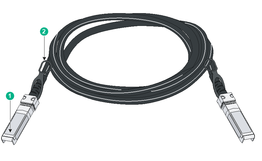
|
(1) Connector |
(2) Pull latch |
|
|
NOTE: · As a best practice, use H3C SFP/SFP+ transceiver modules or SFP+ cables for the SFP+ ports. · The H3C SFP/SFP+ transceiver modules and SFP+ cables available for the SFP+ ports are subject to change over time. For the most up-to-date list of H3C SFP/SFP+ transceiver modules and SFP+ cables available for the SFP+ ports, contact your H3C sales representative or technical support engineer. · For the specifications for the H3C SFP/SFP+ transceiver modules and SFP+ cables, see H3C Transceiver Modules User Guide. |
Combo interface
The S5130S-28P-HPWR-EI, S5130S-28S-HPWR-EI, S5130S-28P-HPWR-EI-AC, and S5130S-28S-HPWR-EI-AC switches each provide four combo interfaces. The S5130S-12TP-EI, S5130S-28TP-EI, S5130S-52TP-EI, S5130S-12TP-HPWR-EI, and S5130S-52F-EI switches each provide two combo interfaces. The S5130S-28F-EI and S5130S-28PS-EI switches provide eight combo interfaces. Each combo interface contains an SFP port and a 10/100/1000BASE-T autosensing Ethernet port. Only one of these two ports operates at a time.
LEDs
System status LED
The system status LED shows the operating status of the switch.
Table4-13 System status LED description
|
LED mark |
Status |
Description |
|
SYS |
Steady yellow |
Boot ROM booting stage. |
|
Steady green |
Linux kernel booting stage, or the switch has started up correctly. |
|
|
Flashing green (1 Hz) |
Software image loading and decompressing stage, or software booting stage. |
|
|
Flashing red (3 Hz) |
The switch has failed POST or the switch is faulty. |
|
|
Off |
The switch is powered off or has not started up correctly. |
Management Ethernet port LED
Table4-14 Management Ethernet port LED description
|
LED mark |
Status |
Description |
|
LINK/ACT |
Steady green |
A link is present on the port. |
|
Flashing green |
The port is sending or receiving data. |
|
|
Off |
No link is present on the port. |
Power supply status LED
The S5130S-28F-EI and S5130S-52F-EI switches provide PWR1 and PWR2 LEDs on the front panel to indicate the operating status of the power supplies.
Table4-15 Power supply status LED description
|
LED mark |
Status |
Description |
|
PWR1/PWR2 |
Steady green |
A power supply is installed in the power supply slot, and the power supply is outputting power correctly. |
|
Steady yellow |
A power supply is installed in the power supply slot, but the power supply is faulty or not powered on. |
|
|
Off |
No power supply is installed in the power supply slot. |
RPS status LED
The S5130S-28P-HPWR-EI, S5130S-52P-PWR-EI, S5130S-10MS-UPWR-EI, S5130S-28S-HPWR-EI, S5130S-52S-PWR-EI, and S5130S-28MP-HPWR-EI switches support RPS input and each provide an RPS status LED on the front panel to indicate the RPS operating status.
Table4-16 RPS status LED description
|
LED mark |
Status |
Description |
|
RPS |
Steady green |
Both the RPS DC input and the AC input are normal. |
|
Steady yellow |
The RPS DC input is normal, but the AC input is disconnected or has failed. |
|
|
Off |
The RPS DC input has failed, or no RPS is connected. |
Mode LED (MODE)
Each PoE switch provides a mode LED (MODE). The mode LED works in conjunction with the Ethernet port LEDs to indicate the operating state of the Ethernet ports and the switch.
You can use the LED mode switching button to change the indication of the mode LED.
Table4-17 Description for the mode LED
|
LED mark |
Status |
Description |
|
Mode LED (MODE) |
Steady green |
The Ethernet port LEDs are showing link state of the ports. |
|
Flashing green |
The Ethernet port LEDs are showing the PoE status of the ports. |
|
|
Flashing yellow |
The Ethernet port LEDs work in conjunction to indicate the IRF member ID of the switch. For example, if the LED for port 5 is steady green, the IRF member ID of the switch is 5. |
SFP/SFP+ port LED
Table4-18 SFP/SFP+ port LED description
|
Status |
Description |
|
Steady green |
A link is present on the port. |
|
Flashing green |
The port is sending or receiving data. |
|
Off |
· No link is present on the port. · The mode LED is operating in PoE mode (available only for PoE switch models) |
Ethernet port LEDs
On a PoE switch, the following Ethernet port LEDs work in conjunction with the mode LED to indicate the operating state of the Ethernet ports and the switch from different aspects. Table4-19 describes the Ethernet port LEDs on a PoE switch.
· 10/100/1000BASE-T autosensing Ethernet port LEDs
· 2.5G/1000/100BASE-T autosensing Ethernet port LEDs
· 5G/2.5G/1000BASE-T autosensing Ethernet port LEDs
· 10/5/2.5/1GBASE-T autosensing Ethernet port LEDs
Table4-20 describes the Ethernet port LEDs on a non-PoE switch.
Table4-19 Ethernet port LED description for PoE switch models
|
Mode LED status |
Ethernet port LED status |
Description |
|
Steady green (Link/Active mode) |
Steady green |
A link is present on the port. |
|
Flashing green |
The port is sending or receiving data. |
|
|
Off |
No link is present on the port. |
|
|
Flashing green (PoE mode) |
Steady green |
PoE power supply is normal. |
|
Flashing green (1 Hz) |
· The maximum PoE power provided by the port fails to meet the power requirement of the PD. · PoE power supply overcurrent, overvoltage, or short-circuit occurs. · The remaining power of the switch fails to meet the power supply requirement of the port. |
|
|
Off |
The port is not connected to a PD or PoE is not enabled on the port. |
|
|
Flashing yellow (IRF mode) |
Steady green |
The Ethernet port LEDs on the switch work in conjunction to indicate the IRF member ID of the switch. For example, if the LED for port 5 is steady green and the other port LEDs are off, the IRF member ID of the switch is 5. |
Table4-20 Ethernet port LED description for non-PoE switch models
|
LED status |
Description |
|
Steady green |
A link is present on the port. |
|
Flashing green |
The port is sending or receiving data. |
|
Off |
No link is present on the port. |
