- Table of Contents
- Related Documents
-
| Title | Size | Download |
|---|---|---|
| 01-Installation Guide | 3.27 MB |
Examining the installation environment
Examining the installation site
Checking power distribution or power supply environment
Installing the switch in a 19-inch rack
Installation procedure at a glance
Rack-mounting the switch by using front mounting brackets
Rack-mounting the switch by using front and rear mounting brackets
Mounting the switch on a workbench
Grounding the switch with a grounding strip
Grounding the switch with a grounding conductor buried in the earth ground
Verifying the connection after grounding the switch
Installing and removing a power supply
Connecting the AC power cord for the fixed AC power supply
Connecting the power cord for a PSR360-56A, PSR720-56A, or PSR1110-56A power supply
Connecting the DC power cord for a PSR560-56D power supply
3 Accessing the switch for the first time
Connecting the switch to a configuration terminal
Connecting a DB9-to-RJ45 console cable
Connecting a USB-to-RJ45 console cable
Connecting a micro USB console cable
Planning IRF fabric size and the installation site
Identifying the master switch and planning IRF member IDs
Planning IRF topology and connections
Identifying IRF physical ports on the member switches
Configuring basic IRF settings
Connecting the IRF physical ports
Verifying the IRF fabric setup
5 Maintenance and troubleshooting
Removable power supply failure
1 Preparing for installation
This document provides an installation guide for the following switch series:
· S5120V3-EI switch series
· S5120V3-LI switch series
· S5120V3-SI switch series
Table1-1 describes the switch models that each switch series includes.
Table1-1 Switch series and models
|
Switch series |
Model |
Product code (PID) |
|
|
S5120V3-EI switch series |
Non-PoE models |
S5120V3-28S-EI |
LS-5120V3-28S-EI |
|
S5120V3-54S-EI |
LS-5120V3-54S-EI |
||
|
S5120V3-28P-EI |
LS-5120V3-28P-EI |
||
|
S5120V3-54P-EI |
LS-5120V3-54P-EI |
||
|
S5120V3-36F-EI |
LS-5120V3-36F-EI |
||
|
PoE models |
S5120V3-28S-HPWR-EI |
LS-5120V3-28S-HPWR-EI |
|
|
S5120V3-54S-PWR-EI |
LS-5120V3-54S-PWR-EI |
||
|
S5120V3-30MS-UPWR-DP-EI |
LS-5120V3-30MS-UPWR-DP-EI |
||
|
S5120V3-LI switch series |
Non-PoE models |
S5120V3-10P-LI |
LS-5120V3-10P-LI LS-5120V3-10P-LI-GL |
|
S5120V3-20P-LI |
LS-5120V3-20P-LI LS-5120V3-20P-LI-GL |
||
|
S5120V3-28S-LI |
LS-5120V3-28S-LI LS-5120V3-28S-LI-GL |
||
|
S5120V3-28P-LI |
LS-5120V3-28P-LI LS-5120V3-28P-LI-GL |
||
|
S5120V3-52S-LI |
LS-5120V3-52S-LI LS-5120V3-52S-LI-GL |
||
|
S5120V3-52P-LI |
LS-5120V3-52P-LI LS-5120V3-52P-LI-GL |
||
|
PoE models |
S5120V3-28S-PWR-LI |
LS-5120V3-28S-PWR-LI LS-5120V3-28S-PWR-LI-GL |
|
|
S5120V3-28P-PWR-LI |
LS-5120V3-28P-PWR-LI LS-5120V3-28P-PWR-LI-GL |
||
|
S5120V3-52S-PWR-LI |
LS-5120V3-52S-PWR-LI LS-5120V3-52S-PWR-LI-GL |
||
|
S5120V3-52P-PWR-LI |
LS-5120V3-52P-PWR-LI LS-5120V3-52P-PWR-LI-GL |
||
|
S5120V3-28P-HPWR-LI-Q |
LS-5120V3-28P-HPWR-LI-Q |
||
|
S5120V3-28P-HPWR-LI |
LS-5120V3-28P-HPWR-LI LS-5120V3-28P-HPWR-LI-GL |
||
|
S5120V3-28S-HPWR-LI |
LS-5120V3-28S-HPWR-LI LS-5120V3-28S-HPWR-LI-GL |
||
|
S5120V3-10P-PWR-LI |
LS-5120V3-10P-PWR-LI LS-5120V3-10P-PWR-LI-GL |
||
|
S5120V3-12TP-HPWR-LI |
LS-5120V3-12TP-HPWR-LI |
||
|
S5120V3-SI switch series |
Non-PoE models |
S5120V3-10P-SI |
LS-5120V3-10P-SI |
|
S5120V3-28P-SI |
LS-5120V3-28P-SI |
||
|
S5120V3-28S-SI |
LS-5120V3-28S-SI |
||
|
S5120V3-52P-SI |
LS-5120V3-52P-SI |
||
|
S5120V3-52S-SI |
LS-5120V3-52S-SI |
||
|
S5120V3-36F-SI |
LS-5120V3-36F-SI |
||
|
PoE models |
S5120V3-28P-HPWR-SI |
LS-5120V3-28P-HPWR-SI |
|
|
S5120V3-54P-PWR-SI |
LS-5120V3-54P-PWR-SI |
||
|
S5120V3-28S-HPWR-SI-Q |
LS-5120V3-28S-HPWR-SI-Q |
||
|
|
NOTE: Switches of the same model but different PIDs might differ in hardware and software features. You can view the PID of a switch on the label located on its rear panel or top panel. |
Safety recommendations
To avoid equipment damage or bodily injury, read the following safety recommendations before installation. Note that the recommendations do not cover every possible hazardous condition.
· Before cleaning the switch, remove all power cords from the switch. Do not clean the switch with wet cloth or liquid.
· Do not place the switch near water or in a damp environment. Prevent water or moisture from entering the switch chassis.
· Do not place the switch on an unstable case or desk. The switch might be severely damaged in case of a fall.
· Ensure good ventilation at the installation site and keep the air inlet and outlet vents of the switch free of obstruction.
· Make sure the operating voltage is as required.
· To avoid electrical shocks, do not open the chassis while the switch is operating or when the switch is just powered off.
· Always wear an ESD wrist strap when installing the switch. Make sure the strap makes good skin contact and is reliably grounded.
Examining the installation environment
To ensure correct operation of your switch, make sure the installation environment meets the requirements listed in Table1-2.
Table1-2 Checking list for the installation environment
|
Item |
Requirements |
|
Ventilation and heat dissipation |
To ensure correct operation of your device, make sure the installation environment is adequately ventilated to prevent the switch from overheating. · Ensure a minimum clearance of 10 cm (3.94 in) around the chassis. · Do not install the device near a heat source, for example, a stove or heater. · Ensure air ventilation in the installation environment. · Do not block the ventilation holes in the device or power adapter. |
|
Anti-moisture |
Water or moisture might damage the circuits of the device. · Do not place the device near water or in a damp environment. · Install the switch in a clean, dry, and ventilated place where temperature is controlled in a stable range. · Make sure the installation environment is free from water leakage or condensation. If required, install a dehumidification device (such as an air conditioner with a dehumidification function or a dedicated dehumidifier). · Do not operate the device under or near the water source, such as the wash basin, laundry room, or areas with high humidity. · Do not touch the device with wet hands. |
|
Temperature/humidity |
For correct operation and long service life of your switch, maintain the temperature and humidity in the equipment room at acceptable ranges. · Lasting high relative humidity can cause poor insulation, electricity leakage, mechanical property change of materials, and metal corrosion. · Lasting low relative humidity can cause washer contraction and ESD and cause issues including loose mounting screws and circuit failure. · High temperature can accelerate the aging of insulation materials and significantly lower the reliability and lifespan of the switch. For the temperature and humidity requirements of the switch, see technical specifications in S5120V3-EI & S5120V3-LI & S5120V3-SI Switch Series Hardware Information and Specifications. |
|
Lightning protection |
Ground the switch correctly and verify the grounding. For more information, see "Grounding the switch." · If you ground the switch by using a grounding strip, make sure the grounding resistance of the grounding strip in the equipment room is less than 1W. · If you ground the switch by using a grounding conductor buried in the earth ground, make sure the grounding resistance of the grounding conductor in the ground is less than 10W. · Route the signal cables along indoor walls, bury the cables in the earth ground, or thread the cables through steel tubes. Install a signal lightning arrester with a nominal discharge current for a corresponding network interface. · Keep the signal cables far from power cords and lightning rod down conductors. · As a best practice, route power cords indoors. If an AC power cord is routed from outdoors, connect the AC power cord first to a power lightning arrester before leading it to the AC power port on the switch. Make sure the power lightning arrester has a nominal discharge current and the total length of the power cord from the power lighting arrester to the power port on the switch is less than 5 m (16.40 ft). · Ground the switch, rack, independent power supplies, and lightning arresters separately. · You must ground optical fibers with reinforcing metal stiffener from outdoors on an optical distribution frame (ODF) or fiber splice enclosure. |
|
Cable routing |
Do not run an Ethernet cable and power cord in parallel. · Route different types of cables separately. · Keep power cords a minimum of 5 cm (1.97 in) away from other cables. |
|
ESD prevention |
· Ground the switch correctly. · To avoid ESD damage to the device or components, always wear an ESD wrist strap when you install or remove the device or components. · Make sure the wrist strap has good skin contact and is reliably grounded. |
|
Cleanliness |
· For more information, see "Cleanliness." |
|
Corrosive gas prevention |
The installation site must be free from corrosive gases such as acid gases and alkaline gases. For more information, see "Corrosive gas limit." |
|
EMI |
· If AC power is used, use a single-phase three-wire power receptacle with protection earth (PE) to filter interference from the power grid. · Keep the device far away from radio transmitting stations, radar stations, and high-frequency devices. · Use electromagnetic shielding, for example, shielded interface cables, when necessary. |
Cleanliness
Dust buildup on the chassis might cause electrostatic adsorption and dust corrosion, resulting in poor contact of metal connectors and contact points. This might shorten the device's lifetime and even cause device failure in the worst case. Table1-3 describes the switch requirement for cleanliness.
Table1-3 Switch requirement for cleanliness
|
Substance |
Particle diameter |
Concentration limit |
|
Dust particles |
≥ 0.5 µm |
≤ 1.8 × 10⁷ particles/m3 |
To maintain cleanliness in the equipment room, follow these guidelines:
· Keep the equipment room away from pollution sources. Do not smoke, eat, or drink in the equipment room.
· Use double-layer glass in windows and seal doors and windows with dust-proof rubber strips. Use screen doors and window screens for doors and windows open to the outside and make sure the external windows are air tight.
· Use dustproof materials for floors, walls, and ceilings and use wallpaper or matt paint that does not produce powders.
· Clean the equipment room regularly and clean the air filters of the rack each month.
· Wear ESD clothing and shoe covers before entering the equipment room, keep the ESD clothing and shoe covers clean, and change them frequently.
Corrosive gas limit
Corrosive gases can accelerate corrosion and aging of metal components. Make sure the corrosive gases do not exceed the concentration limits as shown in Table1-4.
Table1-4 Corrosive gas concentration limits
|
Gas |
Average concentration (mg/m3) |
Maximum concentration (mg/m3) |
|
SO2 |
0.3 |
1.0 |
|
H2S |
0.1 |
0.5 |
|
Cl2 |
0.1 |
0.3 |
|
HCI |
0.1 |
0.5 |
|
HF |
0.01 |
0.03 |
|
NH3 |
1.0 |
3.0 |
|
O3 |
0.05 |
0.1 |
|
NOX |
0.5 |
1.0 |
|
|
CAUTION: As a best practice, control the corrosive gas concentrations in the equipment room at their average values. Make sure the corrosive gas concentrations do not exceed 30 minutes per day at their maximum values. |
To control corrosive gases, use the following guidelines:
· As a best practice, do not build the equipment room in a place with a high concentration of corrosive gases.
· Make sure the equipment room is not connected to sewer, vertical shaft, or septic tank pipelines and keep it far away from these pipelines. The air inlet of the equipment room must be away from such pollution sources.
· Use environmentally friendly materials to decorate the equipment room. Avoid using organic materials that contains harmful gases, such as sulfur or chlorine-containing insulation cottons, rubber mats, sound-proof cottons, and avoid using plasterboards with high sulfur concentration.
· Place fuel (diesel or gasoline) engines separately. Do not place them in the same equipment room with the device. Make sure the exhausted air of the engines will not flow into the equipment room or towards the air inlet of the air conditioners.
· Place batteries separately. Do not place them in the same room with the device.
· Employ a professional company to monitor and control corrosive gases in the equipment room regularly.
Examining the installation site
Before you install the switch, verify that the installation site meets the installation requirements. The switch can operate correctly in an A1 or A2 installation site. Availability issues might occur if you install the switch in an A3, B1, B2, or C installation site.
|
Category |
Definition |
Example |
|
A1: indoor controlled environment |
· Indoor environments where temperature and humidity are controlled. · Completely enclosed or shielded indoor environments. |
Central equipment rooms, IDC equipment rooms, mobile cabins with air conditioners, outdoor air conditioner cabinets, and heat exchanger cabinets. |
|
A2: indoor partially controlled environment |
· Indoor environments where temperature and humidity are partially controlled. · Incompletely enclosed or shielded places. · Places far from pollution sources. |
Simple equipment rooms, ordinary houses, garages, corridors, and direct ventilation cabinets far from pollution sources, houses without direct exposure to sunlight or rain, railway station platforms, and stadiums. |
|
A3: indoor uncontrolled environment |
· Indoor environments where temperature and humidity are uncontrolled. · Incompletely enclosed or shielded places. · Places near pollution sources. |
Simple equipment rooms, ordinary houses, garages, corridors, and direct ventilation cabinets near pollution sources, houses without direct exposure to sunlight or rain, railway station platforms, stadiums, uncleaned rooms after decoration, and rooms under decoration. |
|
B1: outdoor general environment |
· Unshielded places where the temperature and humidity are not controlled. · Places far from pollution sources. |
Completely exposed outdoor places far from pollution sources. |
|
B2: harsh environment |
· Unshielded places where the temperature and humidity are not controlled. · Sea environments or outdoor land environments near pollution sources. |
Islands, ships, and completely exposed outdoor places near pollution sources. |
|
C: special environments |
Special application environments |
Buried, underwater, or undersea environments and manholes. |
Table1-6 Pollution sources
|
Category |
Radius range |
|
Saline water areas such as oceans and saline lakes |
≤ 3.7 km (2.30 miles) |
|
Serious pollution sources such as metallurgic plants, coal mines, and heat and power plants |
≤ 3 km (1.86 miles) |
|
Medium pollution sources such as chemical factories, rubber plants, and electroplating factories |
≤ 2 km (1.24 miles) |
|
Light pollution sources, such as food factories, tanneries, and heating boilers |
≤ 1 km (0.62 miles) |
Checking power distribution or power supply environment
Table1-7 Requirements for power distribution or power supply environment
|
Item |
Requirements |
|
Preparation |
The power supply must be available before you install the switch. |
|
Voltage |
The voltage provided to the switch must be within the operating voltage range. For the operating voltage range, see S5120V3-EI & S5120V3-LI & S5120V3-SI Switch Series Hardware Information and Specifications. |
|
Power receptacle and cables |
· If the external power supply system provides an AC power outlet, use a country-specific AC power cord. Make sure the PE wire of the AC power supply is grounded reliably. · If the external power supply system provides a DC distribution box, prepare DC power cords yourself. · Do not use the power cord provided with the switch on other devices. |
Laser safety
|
|
WARNING! Disconnected optical fibers or transceiver modules might emit invisible laser light. Do not stare into beams or view directly with optical instruments when the switch is operating. |
The switch is a Class 1 laser device.
Installation tools
No installation tools are provided with the switch. Prepare the following tools yourself as required:
· ESD wrist strap
· Flat-head screwdriver
· Phillips screwdriver
· Needle-nose pliers
· Marker
Installation accessories
Before installation, make sure you have all the required installation accessories. If any accessory is damaged or missing, use the product code provided in this table to purchase a new one.
Table1-8 Installation accessories
|
Product code |
Description |
Quantity |
Applicable device models |
|
2150A0F4 |
Front mounting bracket kit, including two front mounting brackets and four M4 screws
|
1 kit (provided) |
S5120V3-LI switch series (excluding the S5120V3-10P-LI, S5120V3-20P-LI, S5120V3-10P-PWR-LI, and S5120V3-12TP-HPWR-LI switches) S5120V3-28P-SI S5120V3-28S-SI S5120V3-52P-SI S5120V3-52S-SI S5120V3-28S-HPWR-SI-Q |
|
2150A03X |
Front mounting bracket kit (including two front mounting brackets and eight M4 screws)
|
1 kit (provided) |
S5120V3-EI switch series S5120V3-36F-SI S5120V3-28P-HPWR-SI S5120V3-54P-PWR-SI |
|
2150A0BP |
Rear mounting bracket kit (including two rear mounting brackets and two shoulder screws)
|
1 kit (provided) |
S5120V3-30MS-UPWR-DP-EI |
|
SOHO-SWITCH-FL-02 |
Front mounting bracket kit (including two front mounting brackets and four M4 screws)
|
1 kit (optional) |
S5120V3-12TP-HPWR-LI S5120V3-10P-PWR-LI S5120V3-20P-LI |
|
SOHO-SWITCH-FL-01 |
Front mounting bracket kit (including two front mounting brackets and four M4 screws)
|
1 kit (optional) |
S5120V3-10P-SI S5120V3-10P-LI |
|
N/A |
M6 screw and cage nut
|
User supplied |
All switch models |
|
N/A |
Rubber feet
|
4 (provided) |
All switch models |
|
N/A |
Grounding cable
|
1 (provided) |
All switch models |
|
N/A |
Grounding screw
|
1 (provided) |
All switch models |
|
N/A |
AC power cord
The appearance and parameters for AC power cords vary by countries and regions. The power cord in this table is a standard power cord in China. |
1, provided for the switch with a fixed power supply 1, provided with removable power supplies |
All switch models |
|
N/A |
DC power cord
|
1, provided with removable DC power supplies |
S5120V3-30MS-UPWR-DP-EI |
|
04042967 |
DB9-to-RJ45 console cable
|
1 (optional) |
All switch models |
|
0404A1EE |
USB-to-RJ45 console cable
|
1 (optional) |
All switch models |
|
N/A |
Micro USB console cable
|
1 (user supplied) |
S5120V3-28P-HPWR-LI-Q S5120V3-28S-HPWR-SI-Q |


2 Installing the switch
|
|
CAUTION: Keep the tamper-proof seal on a mounting screw on the chassis cover intact, and if you want to open the chassis, contact H3C for permission. Otherwise, H3C shall not be liable for any consequence. |
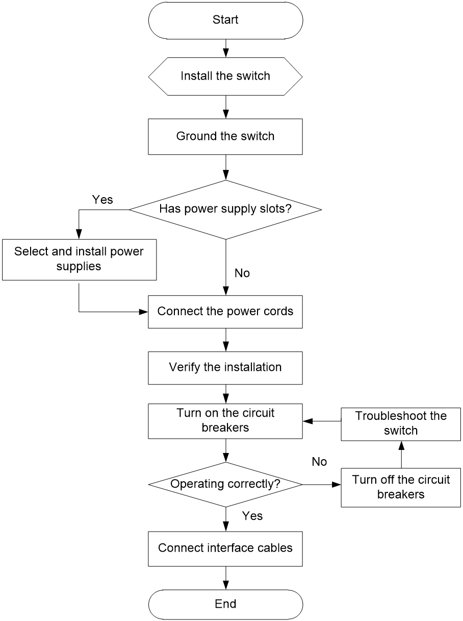
Figure2-1 Hardware installation flow
Installing the switch in a 19-inch rack
Installation methods
|
Switch models |
Installation method |
Mounting bracket type |
Description |
Installation procedure |
|
S5120V3-LI switch series (excluding the S5120V3-10P-LI, S5120V3-20P-LI, S5120V3-10P-PWR-LI, and S5120V3-12TP-HPWR-LI switches) S5120V3-28P-SI S5120V3-28S-SI S5120V3-52P-SI S5120V3-52S-SI S5120V3-28S-HPWR-SI-Q |
Using front mounting brackets |
Mounting bracket A (provided), as shown by callout (A) in Figure2-2 |
Select an installation position for the front mounting brackets as required: near the power supply side or port side. For the S5120V3-28S-EI, S5120V3-54S-EI, S5120V3-28P-EI, S5120V3-54P-EI, S5120V3-36F-EI, S5120V3-28P-HPWR-LI-Q, S5120V3-28P-SI, S5120V3-28S-SI, S5120V3-52P-SI, S5120V3-52S-SI, S5120V3-36F-SI, or S5120V3-28S-HPWR-SI-Q switch, or the S5120V3-LI switch series, the front mounting brackets can be installed only near the port side. |
See "Rack-mounting the switch by using front mounting brackets." |
|
S5120V3-EI switch series (excluding the S5120V3-30MS-UPWR-DP-EI switch) S5120V3-36F-SI S5120V3-28P-HPWR-SI S5120V3-54P-PWR-SI |
Mounting bracket B (provided), as shown by callout (B) in Figure2-2 |
|||
|
S5120V3-12TP-HPWR-LI S5120V3-10P-PWR-LI S5120V3-20P-LI |
Mounting bracket C (optional, with a product code of SOHO-SWITCH-FL-02), as shown by callout (C) in Figure2-2 |
N/A |
||
|
S5120V3-10P-SI S5120V3-10P-LI |
Mounting bracket D (optional, with a product code of SOHO-SWITCH-FL-01), as shown by callout (D) in Figure2-2 |
N/A |
||
|
S5120V3-30MS-UPWR-DP-EI |
Using front and rear mounting brackets |
Mounting bracket B (provided), as shown by callout (B) in Figure2-2 Rear mounting bracket (provided), as shown in Figure2-3 |
· Select an installation position for the front mounting brackets as required: near the power supply side or port side. · Install the rear mounting brackets based on the rack depth (distance between the front and rear rack posts). ¡ If the rack depth is in the range of 429 to 595 mm (16.89 to 23.43 in), orient the rear mounting brackets with the wide flange inside the rack. ¡ If the rack depth is in the range of 274 to 440 mm (10.79 to 17.32 in) and the distance from the rear rack posts to the inner surface of the cabinet door is greater than 153 mm (6.02 in), orient the rear mounting brackets with the wide flange outside the rack. · If you are to install a PSR1110-56A power supply, make sure the rack depth is larger than 600 mm (23.62 in). |
See "Rack-mounting the switch by using front and rear mounting brackets." |
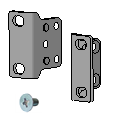
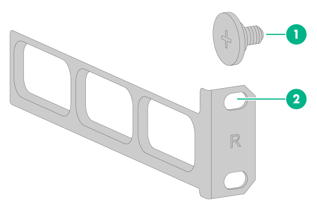
Figure2-2 Front mounting brackets

|
(1) Screw hole for attaching the mounting bracket to the switch |
|
(2) Screw hole for attaching the mounting bracket to the rack |
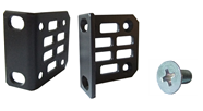
Figure2-3 Rear mounting bracket and shoulder screw
|
(1) Shoulder screw |
|
(2) Screw hole for attaching the mounting bracket to the rack |
Installation procedure at a glance
Figure2-4 Procedure for installing the switch in a 19-inch rack by using front mounting brackets
Figure2-5 Procedure for installing the switch in a 19-inch rack by using front and rear mounting brackets

|
|
NOTE: If a rack shelf is available, you can put the switch on the rack shelf, slide the switch to an appropriate location, and then attach the switch to the rack by using the mounting brackets. |
Rack-mounting the switch by using front mounting brackets
This installation method is applicable to all switches except for the S5120V3-30MS-UPWR-DP-EI switch.
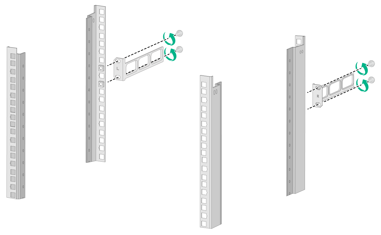
Attaching the front mounting brackets to the switch
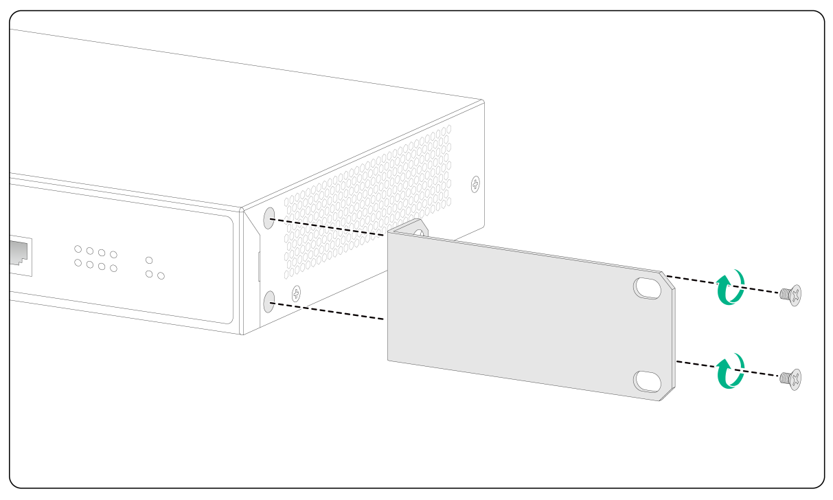
1. Place the wide flange of the front mounting bracket against the chassis side panel. Align the mounting bracket installation holes with the screw holes in the chassis.
2. Fasten the M4 screws to secure the mounting bracket to the switch. As a best practice, use a torque of 12 kgf-cm (1.18 Nm) to fasten the M4 screws.
¡ To attach mounting bracket A to the switch, see Figure2-6.
¡ To attach mounting bracket B to the switch, see Figure2-7 and Figure2-8.
¡ To attach mounting bracket C to the switch, see Figure2-9.
¡ To attach mounting bracket D to the switch, see Figure2-10.
Figure2-6 Attaching mounting bracket A to the port-side mounting position (S5120V3-52P-PWR-LI)
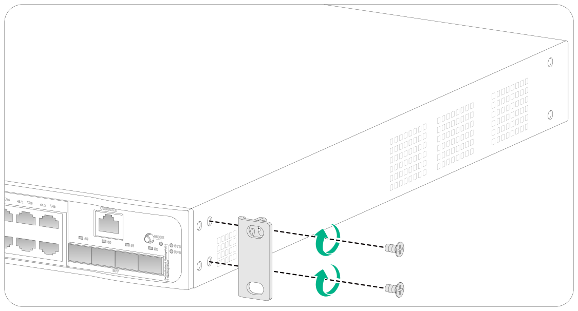
Figure2-7 Attaching mounting bracket B to the port-side mounting position (S5120V3-28S-HPWR-EI)
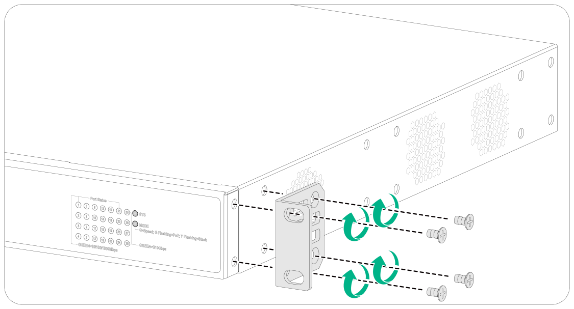
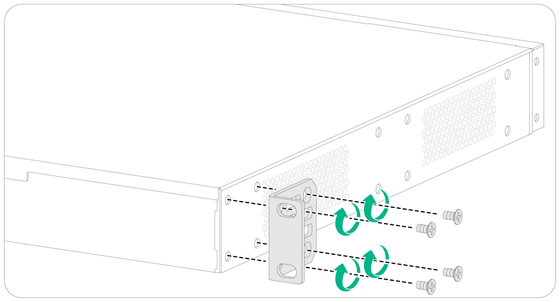
Figure2-9 Attaching mounting bracket C to the switch (S5120V3-10P-PWR-LI)
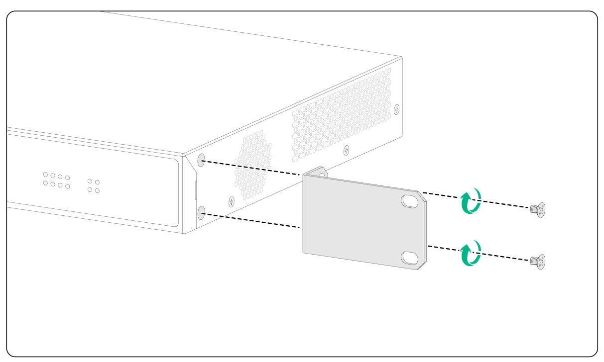
Figure2-10 Attaching mounting bracket D to the switch (S5120V3-10P-LI)
3. Attach the front mounting bracket to the other side of the chassis in the same way.
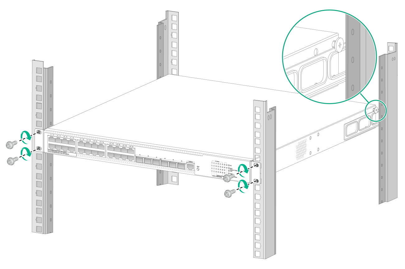
Mounting the switch in the rack
1. Wear an ESD wrist strap and make sure it makes good skin contact and is reliably grounded.
2. Verify that the front mounting brackets have been securely attached to the switch chassis. See "Attaching the front mounting brackets to the switch."
3. Attach cage nuts to the front rack posts.
4. One person supports the bottom of the switch, and moves the switch to an appropriate position based on the installation positions of the front mounting brackets.
5. Another person uses user supplied M6 screws and cage nuts to attach the mounting brackets to the rack and verifies that the brackets are level and secure. As a best practice, use a torque of 30 kgf-cm (2.94 Nm) to fasten the M6 screws.
Figure2-11 Mounting the switch in the rack (port-side mounting position for mounting brackets A on an S5120V3-52P-PWR-LI)
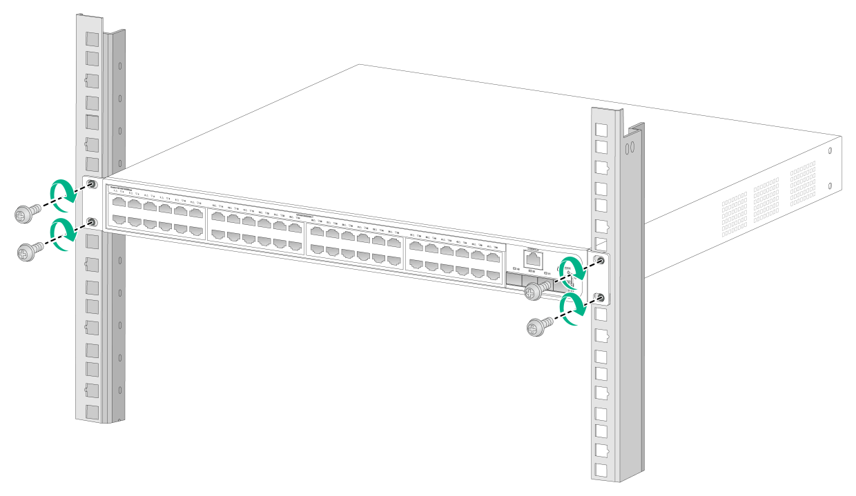
Figure2-12 Mounting the switch in the rack (port-side mounting position for mounting brackets B on an S5120V3-28S-HPWR-EI)
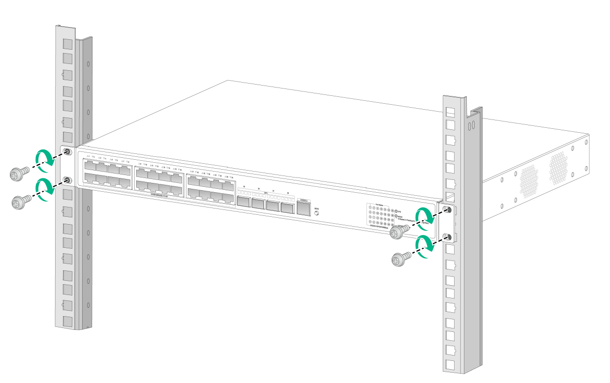
Figure2-13 Mounting the switch in the rack (power supply-side mounting position for mounting brackets B on an S5120V3-28S-HPWR-EI)
Figure2-14 Mounting the switch in the rack by using mounting brackets C (S5120V3-10P-PWR-LI)
Figure2-15 Mounting the switch in the rack by using mounting brackets D (S5120V3-10P-LI)
Rack-mounting the switch by using front and rear mounting brackets
This installation method is applicable to the S5120V3-30MS-UPWR-DP-EI switch.
Attaching the front mounting brackets and shoulder screws to the switch
The switch provides two installation positions on its side for the front mounting brackets. One is near the power supply side and the other is near the port side. The following procedure describes how to attach the front mounting brackets to the installation position near the port side. The power supply-side mounting is similar.
To attach the front mounting brackets and shoulder screws to the switch:
1. Place the wide flange of the front mounting bracket against the chassis side panel. Align the mounting bracket installation holes with the screw holes in the chassis. See Figure2-16.
2. Use M4 screws to attach the mounting bracket to the chassis, and then fasten the M4 screws. As a best practice, use a torque of 12 kgf-cm (1.18 Nm) to fasten the M4 screws.
3. Repeat the preceding two steps to attach the other mounting bracket to the chassis.
4. Unpack the shoulder screws and attach them to the chassis. As a best practice, use a torque of 12 kgf-cm (1.18 Nm) to fasten the shoulder screws.
Two installation positions as red-marked in Figure2-16 are available for shoulder screws. Select one as required.
Figure2-16 Attaching the front mounting brackets and shoulder screws to the chassis (port-side mounting position for mounting brackets)
Attaching the rear mounting brackets to the rack
1. Determine the switch installation position in the rack.
2. Orient the rear mounting brackets with the wide flange inside or outside the rack as required.
3. Use M6 screws and cages nuts (user-supplied) to attach the rear mounting brackets to the rear rack posts. As a best practice, use a torque of 30 kgf-cm (2.94 Nm) to fasten the M6 screws.
Do not fully tighten the M6 screws before mounting the switch in the rack.
Figure2-17 Attaching the rear mounting brackets to the rack with the wide flange inside the rack
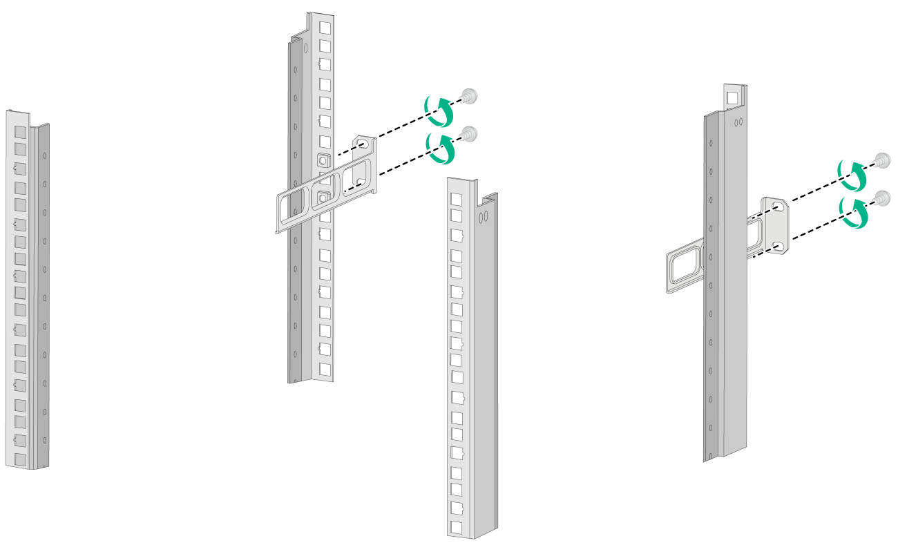
Figure2-18 Attaching the rear mounting brackets to the rack with the wide flange outside the rack
Mounting the switch in the rack
1. Wear an ESD wrist strap and make sure it makes good skin contact and is reliably grounded.
2. Make sure the front mounting brackets and shoulder screws are securely attached to the two sides of the switch. For more information, see "Attaching the front mounting brackets and shoulder screws to the switch."
3. Attach cage nuts to the front rack posts.
4. One person supports the chassis bottom, moves the switch to an appropriate position based on the installation positions of the front mounting brackets, and then pushes the chassis into the rack gently. Make sure the shoulder screws rest firmly on the upper edge of the rear mounting brackets. See Figure2-19 and Figure2-20.
5. The other person uses M6 screws and cage nuts to attach the front mounting brackets to the front rack posts. Make sure the switch is installed securely in the rack. See Figure2-19 and Figure2-20. As a best practice, use a torque of 30 kgf-cm (2.94 Nm) to fasten the M6 screws.
Figure2-19 Mounting the switch in the rack (with the wide flange of the rear mounting brackets inside the rack)

Mounting the switch on a workbench
|
|
IMPORTANT: · Ensure 10 cm (3.9 in) of clearance around the chassis for heat dissipation. · Do not place heavy objects on the switch. |
If a standard 19-inch rack is not available, you can place your switch on a workbench.
To mount the switch on a workbench:
1. Verify that the workbench is sturdy and reliably grounded.
2. Place the switch with bottom up, and clean the round holes in the chassis bottom with dry cloth.
3. Attach the rubber feet to the four round holes in the chassis bottom.
4. Place the switch with upside up on the workbench.
Mounting the switch on a wall
|
|
CAUTION: · Before drilling holes in a wall, make sure no electrical lines exist in the wall. · Leave a minimum clearance of 10 mm (0.39 in) around the chassis for heat dissipation. |
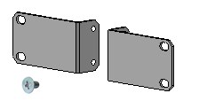
The S5120V3-SI and S5120V3-LI switch series support wall mounting. These switches are provided with screw anchors and screws as shown in Figure2-21 for wall-mounting.
Figure2-21 Screw anchor and screw

Table2-3 describes the switch models that support wall mounting and installation holes distances required for wall-mounting the switch.
Table2-3 Installation hole distances for switch models that support wall mounting
|
Switch model |
Hole distance |
|
S5120V3-10P-LI S5120V3-10P-SI |
170 mm (6.69 in) |
|
S5120V3-10P-PWR-LI S5120V3-12TP-HPWR-LI |
102 mm (4.02 in) |
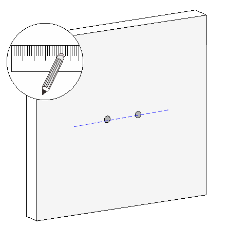
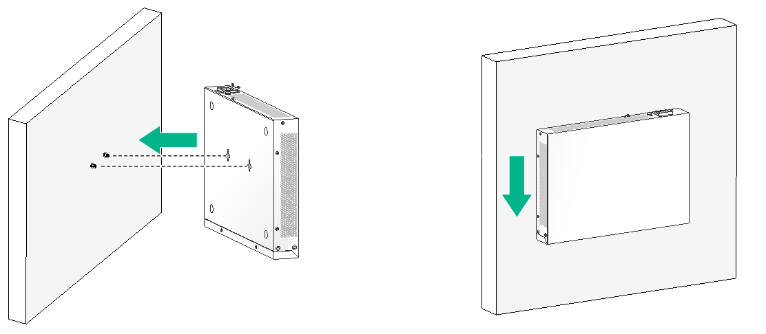
To mount the switch on a wall:
1. Mark two installation holes on the wall. Make sure the two holes are on the same horizontal line.
See Table2-3 for the distance requirement between the two holes.
Figure2-22 Installing the switch on a wall (1)
2. Drill two holes with a diameter of 6 mm (0.24 in) and a depth of 25 mm (0.98 in) at the marked locations. Hammer the screw anchors into the wall and use a Phillips screwdriver to fasten the screw into the screw anchor. Leave 1.5 mm (0.06 in) between the screw head and the wall for hanging the switch.
Figure2-23 Installing the switch on a wall (2)
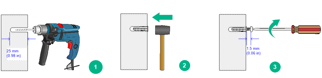
3. Align the installation holes in the switch rear with the screws on the wall and hang the switch on the screws. Make sure the port side faces down and the left and right sides are perpendicular to the ground.
Figure2-24 Installing the switch on a wall (3)
Grounding the switch
|
|
WARNING! Correctly connecting the switch grounding cable is crucial to lightning protection, ESD, and EMI protection. For information about lightning protection, see H3C Network Devices Lightning Protection Guide. |
To protect against the following types of problems, use a grounding cable to connect the device to the earthing facility at the installation site:
· Bodily injury from electric shocks.
· Device and power and data line damages.
· Electrical fires, lightning strokes, electromagnetic coupling interferences, ESD damages.
You can ground the switch in one of the following ways, depending on the grounding conditions available at the installation site:
· Grounding the switch with a grounding strip
· Grounding the switch with a grounding conductor buried in the earth ground
|
|
NOTE: The chassis views and power supply and grounding terminal positions in the following figures are for illustration only. |
Grounding the switch with a grounding strip
|
|
WARNING! Connect the grounding cable to the grounding system in the equipment room. Do not connect it to a fire main or lightning rod. |
If a grounding strip is available at the installation site, use the grounding strip to ground the switch.
To ground the switch by using a grounding strip:
1. Attach the ring terminal end of the grounding cable to the grounding hole in the switch.
a. Remove the grounding screw from the grounding hole in the rear panel of the switch.
b. Attach the grounding screw to the ring terminal of the grounding cable.
c. Use a screwdriver to fasten the grounding screw into the grounding screw hole.
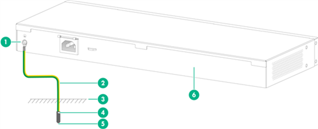
Figure2-25 Attaching the grounding cable to the grounding hole of the switch
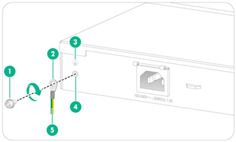
|
(1) Grounding screw |
(2) Ring terminal |
|
(3) Grounding sign |
(4) Grounding hole |
|
(5) Grounding cable |
|
2. Connect the other end of the grounding cable to the grounding strip.
a. Cut the grounding cable to a length according to the distance between the switch and the grounding strip.
b. Peel 20 mm (0.79 in) of insulation sheath by using a wire stripper.
c. Use the needle-nose pliers to bend the bare wire.
d. Hook the grounding cable to the post on the grounding strip, and use the hex nut to secure the cable to the post.
Figure2-26 Connecting the grounding cable to a grounding strip
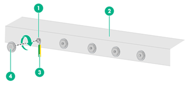
|
(1) Grounding post |
(2) Grounding strip |
|
(3) Grounding cable |
(4) Hex nut |
Grounding the switch with a grounding conductor buried in the earth ground
If the installation site does not have grounding strips, but earth ground is available, hammer a 2.5 m (8.20 ft) or longer angle iron or steel tube into the earth ground to act as a grounding conductor. Make sure a minimum of 0.7 m (2.30 ft) is left between the top of the grounding conductor and the ground. In cold areas, bury the grounding conductor below the frozen soil layer. In areas with thin soil or rocky gravel, determine the depth for burying the grounding conductor based on the actual condition.
If zinc-coated steel is used, the following dimensions requirements must be met:
· Angle iron—A minimum of 50 × 50 × 5 mm (1.97 × 1.97 × 0.20 in).
· Steel tube—A minimum of 3.5 mm (0.14 in) in thickness.
· Flat steel—A minimum of 40 × 4 mm (1.57 × 0.16 in).
· Round steel—A minimum of 10 mm (0.39 in).
Weld the yellow-green grounding cable to the angel iron or steel tube and treat the joint for corrosion protection.
Figure2-27 Grounding the switch by burying the grounding conductor into the earth ground
|
(1) Grounding screw |
(2) Grounding cable |
(3) Earth |
|
(4) Joint |
(5) Grounding conductor |
(6) Chassis rear panel |
Verifying the connection after grounding the switch
· If you ground the switch by using a grounding strip, perform the following tasks:
a. Use a multimeter to measure the resistance between the switch grounding terminal and grounding point, and make sure the resistance is less than 0.1W.
b. Use a grounding resistance tester to measure the grounding resistance of the grounding strip, and make sure the grounding resistance is less than 1W.
· If you ground the switch with a grounding conductor buried in the earth ground, perform the following tasks:
a. Use a multimeter to measure the resistance between the switch grounding terminal and grounding point, and make sure the resistance is less than 0.1W.
b. Use a grounding resistance tester to measure the grounding resistance of the angle iron in the ground, and make sure the grounding resistance is less than 10W. For locations with high soil resistivity, sprinkle some resistance reducer to reduce soil resistivity or replace soil around the grounding strip with soil with lower resistance.
For information about resistance measurement, see H3C Network Devices Lightning Protection Guide.
Installing and removing a power supply
|
WARNING! In power redundancy mode, you can replace a power supply without powering off the switch but you must strictly follow the installation and removal procedures in Figure2-28 and Figure2-29 to avoid any bodily injury or damage to the switch. |
|
|
CAUTION: Provide a circuit breaker for each power supply. |
Figure2-28 Installation procedure
![]()
![]()
The S5120V3-30MS-UPWR-DP-EI switch came with power supply slot 1 empty and power supply slot 2 installed with a filler panel. You can install one or two power supplies for the switch as required.
For the power supplies available for the switch and their specifications, see S5120V3-EI & S5120V3-LI & S5120V3-SI Switch Series Hardware Information and Specifications.
The installation and removal procedures are the same for the PSR360-56A, PSR560-56D, PSR720-56A, and PSR1110-56A power supplies. The following uses the PSR360-56A power supply as an example.
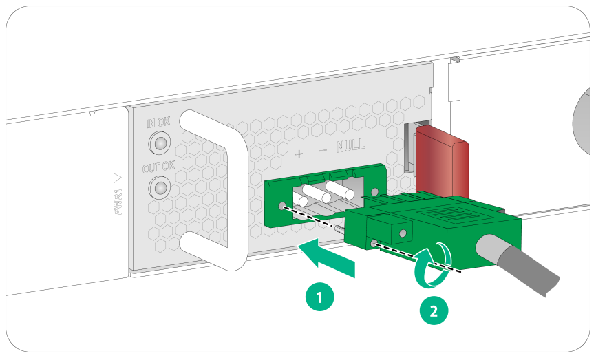
Installing a power supply
|
|
CAUTION: · Follow the forward inertia of the power supply when inserting it into the chassis, and make sure the power supply has firm contact with the connectors on the backplane. · To prevent damage to the power supply and the connectors on the backplane, insert the power supply gently. If you encounter a hard resistance when inserting the power supply, pull out the power supply and insert it again. |
To install a power supply:
1. Wear an ESD wrist strap and make sure it makes good skin contact and is reliably grounded.
2. Remove the filler panel, if any, from the target power supply slot.
Put your finger into the hole in the filler panel, and then pull the filler panel out of the slot gently.
Figure2-30 Removing the filler panel from the target power supply slot
3. Unpack the power supply. Make sure the power supply model is as required.
Keep the packaging box and packaging bag for the power supply secure for future use.
4. Correctly orient the power supply with the lettering on it facing upward. Align the power supply with the power supply slot. Grasping the power supply handle with one hand and supporting its bottom with the other, slide the power supply slowly into the slot along the guide rails until the latch of the power supply clicks into the slot.
Figure2-31 Installing a power supply
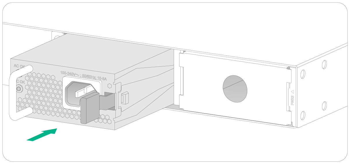
Figure2-32 Installation completed
|
|
NOTE: The PSR1110-56A power supply, including its handle, adds 64 mm (2.52 in) to chassis depth. |
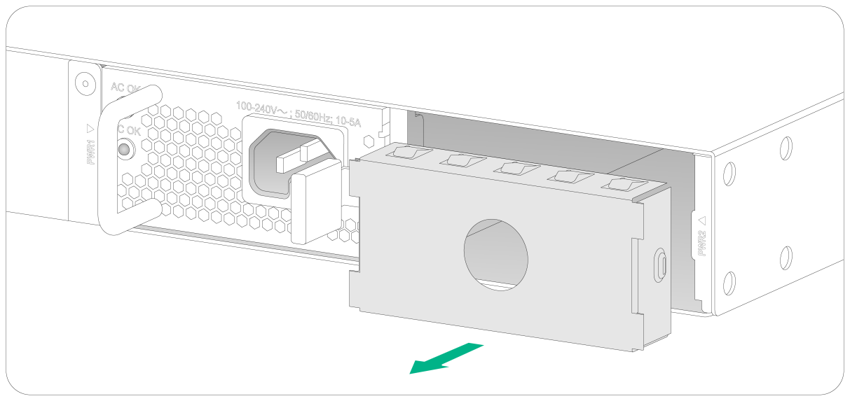
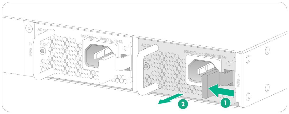
Removing a power supply
1. Wear an ESD wrist strap and make sure it makes good skin contact and is reliably grounded.
2. Disconnect the power cord.
3. Press the latch towards the handle, and then pull the power supply part way out along the guide rails.
4. Grasping the power supply handle with one hand, supporting the bottom with the other, pull the power supply slowly out of the slot along the guide rails.
5. Keep the removed power supply in an antistatic bag or the power supply package bag for future use.
6. Install the filler panel in the slot to prevent dust and ensure good ventilation if you are no to install a new power supply in the slot.
Figure2-33 Removing a power supply
Connecting the power cord
|
|
WARNING! · Provide a circuit breaker for each power cord. · Before connecting the power cord, make sure the circuit breaker for the power cord is turned off. |
Table2-4 Power cord connection procedures at a glance
|
Power supply model |
Available power source |
Connection procedure reference |
|
Fixed power supply |
AC power source |
|
|
PSR360-56A/PSR720-56A/PSR1110-56A |
AC power source |
Connecting the power cord for a PSR360-56A, PSR720-56A, or PSR1110-56A power supply |
|
PSR560-56D |
–48 VDC power source in the equipment room |
|
|
RPS1600-A |
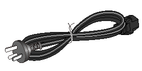
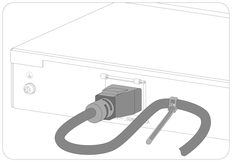
Connecting the AC power cord for the fixed AC power supply
1. Wear an ESD wrist strap and make sure it makes good skin contact and is reliably grounded.
2. Connect the female connector of the AC power cord to the AC-input power receptacle on the switch. See Figure2-34.
3. Use a cable tie to secure the power cord to the handle near the AC-input power receptacle. See Figure2-35.
4. Connect the other end of the power cord to an AC power source.
Figure2-34 Connecting the AC power cord for the fixed AC power supply (1)
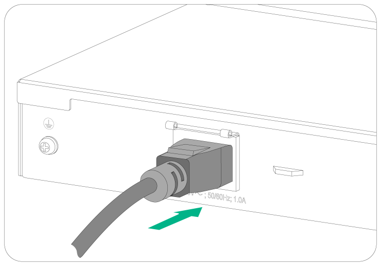
Figure2-35 Connecting the AC power cord for the fixed AC power supply (2)
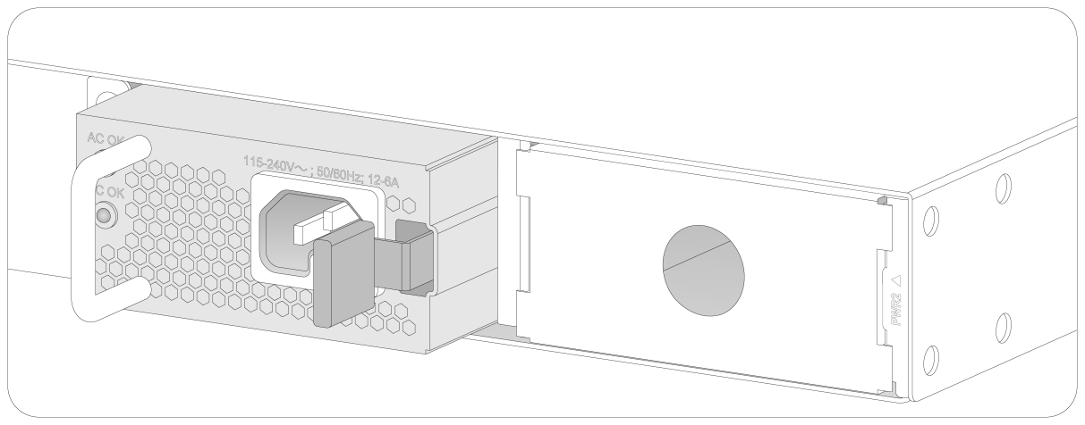
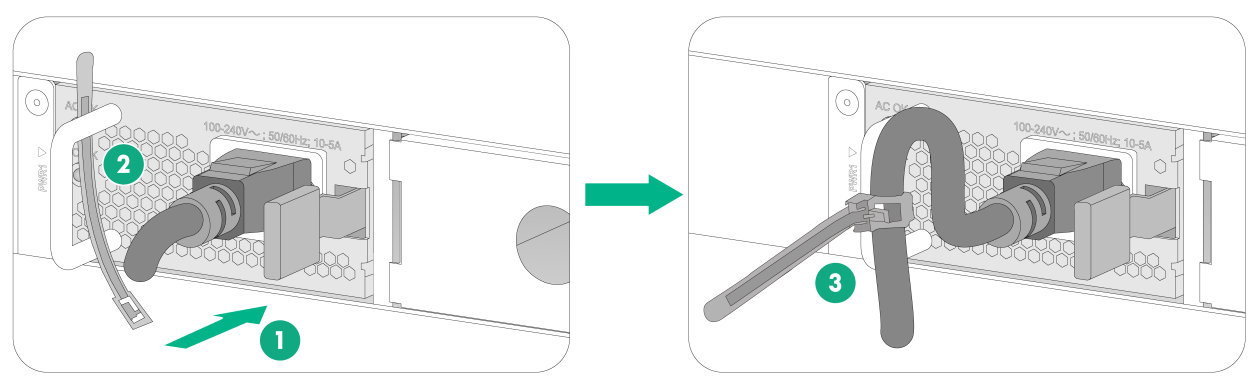
Connecting the power cord for a PSR360-56A, PSR720-56A, or PSR1110-56A power supply
The power cord connection procedure is the same for the PSR360-56A, PSR720-56A, and PSR1110-56A power supplies. The following procedure uses a PSR360-56A power supply as an example.
To connect the power cord for a PSR360-56A power supply:
1. Wear an ESD wrist strap and make sure it makes good skin contact and is reliably grounded.
2. Plug the female connector end of the power cord into the power receptacle on the power supply (see callout 1 in Figure2-36).
3. Use a releasable cable tie to secure the power cord to the handle of the power supply (see callout 2 and callout 3 in Figure2-36).
4. Connect the other end of the power cord to a power source.
For a PSR360-56A, PSR720-56A, or PSR1110-56A power supply, you can connect the power cord only to an AC power source.
Figure2-36 Connecting the power cord for a PSR360-56A power supply
Connecting the DC power cord for a PSR560-56D power supply
|
|
CAUTION: · To use a –48 VDC power source to supply power to the power supply, use the DC power cord supplied with the power supply. · To use an H3C RPS to supply power to the power supply, use a compatible RPS power cord to connect the RPS to the power supply. · To connect the switch to a –48 VDC power source, identify the positive (+) and negative (-) marks on the DC power wires to ensure correct connections. |
To connect the power cord for a PSR560-56D power supply:
1. Wear an ESD wrist strap and make sure it makes good skin contact and is reliably grounded.
2. Correctly orient the power cord connector, and then insert the connector into the power receptacle on the power supply (see callout 1 in Figure2-37).
The power cord connector and power receptacle are designed to prevent misalignment. If you cannot insert the connector into the receptacle, re-orient the connector rather than use excessive force to push it in.
3. Fasten the screws on the power cord connector with a flat-head screwdriver to secure the connector to the power receptacle (see callout 2 in Figure2-37).
4. Connect the other end of the power cord to a –48 VDC power source or an RPS.
Figure2-37 Connecting the power cord for a PSR560-56D power supply
Verifying the installation
After you complete the installation, verify the following items:
· There is enough space for heat dissipation around the switch, and the rack or workbench is stable.
· The grounding cable is securely connected.
· The power source is as required by the switch.
· The power cords are connected correctly.
· If part of the network cable for a port is routed outdoors, verify that a network port lightning protector is used for the port.
· If a power line is routed from outdoors, verify that a surge protected power strip is used for the switch.
|
|
NOTE: For information about lightning protection for the switch, see H3C Lightning Protection Guide. |
3 Accessing the switch for the first time
Connecting the switch to a configuration terminal
The following switch models each provide a serial console port and a micro USB console port. You can access the switch from either port. If you connect both ports, only the micro USB console port is available.
· S5120V3-28P-HPWR-LI-Q
· S5120V3-28S-HPWR-SI-Q
· S5120V3-28S-HPWR-LI
The other switch models each provide only a serial console port.
In Figure3-1, the switch is connected to a configuration terminal (PC as an example) from the serial console port.
Figure3-1 Connecting the switch to a configuration terminal
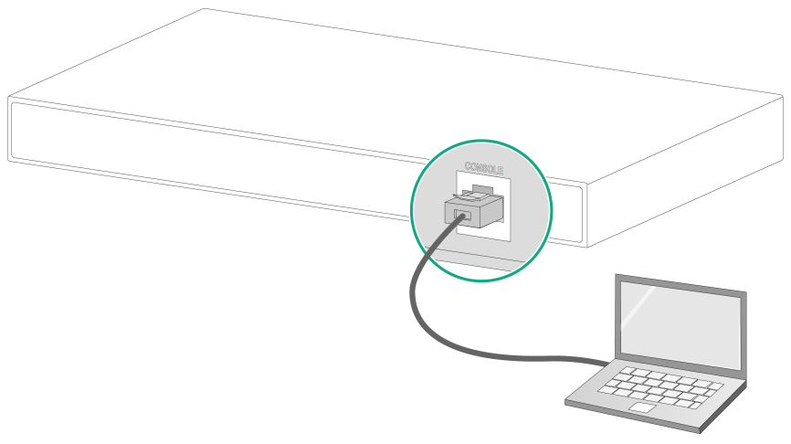
As shown in Figure3-1, three types of console cables can be used for connecting the switch to a configuration terminal. The switch is not provided with a serial console cable or a micro USB console cable.
Table3-1 Connection methods and console cables
|
Connection method |
Console cable type |
Configuration terminal-side connector |
Switch-side connector |
|
Using the serial console port for connection |
DB9-to-RJ45 console cable |
DB-9 female connector |
RJ-45 connector |
|
USB-to-RJ45 console cable |
USB connector |
RJ-45 connector |
|
|
Using the micro USB console port for connection |
Micro USB console cable |
USB connector |
Micro USB connector |
The signal pinout for the RJ-45 connector of a serial console cable varies by vendor. To avoid abnormal configuration terminal display, use a serial console cable provided by H3C. For more information, see Table1-8. To prepare a serial console cable yourself, make sure the signal pinout for the RJ-45 connector is the same as that shown in Table3-2.
Connecting a DB9-to-RJ45 console cable
|
|
CAUTION: Follow these guidelines when you connect a DB9-to-RJ45 console cable: · Identify the mark on the serial console port and make sure you are connecting to the correct port. · The serial ports on PCs do not support hot swapping. To connect a PC to an operating switch, first connect the PC end. To disconnect a PC from an operating switch, first disconnect the switch end. |
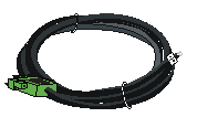
A DB9-to-RJ45 serial console cable is an 8-core shielded cable, with a crimped RJ-45 connector at one end for connecting to the serial console port of the switch, and a DB-9 female connector at the other end for connecting to the serial port on a configuration terminal.
Figure3-2 DB9-to-RJ45 console cable
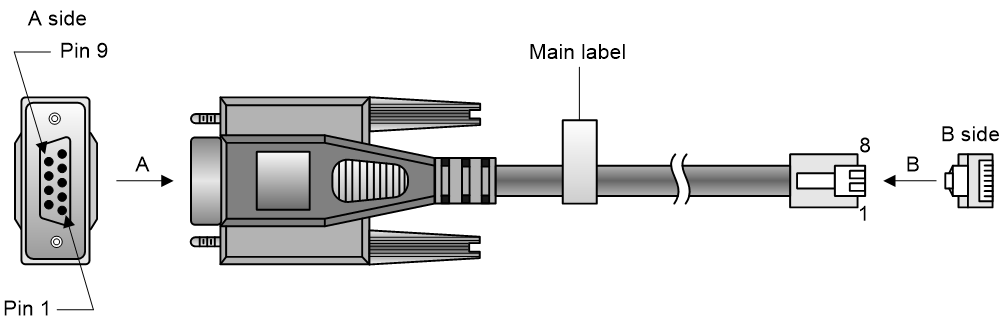
Table3-2 DB9-to-RJ45 console cable signal pinout
|
RJ-45 |
Signal |
DB-9 |
Signal |
|
1 |
RTS |
8 |
CTS |
|
2 |
DTR |
6 |
DSR |
|
3 |
TXD |
2 |
RXD |
|
4 |
SG |
5 |
SG |
|
5 |
SG |
5 |
SG |
|
6 |
RXD |
3 |
TXD |
|
7 |
DSR |
4 |
DTR |
|
8 |
CTS |
7 |
RTS |
To connect the switch to a configuration terminal (for example, a PC) by using a DB9-to-RJ45 console cable:
1. Plug the DB-9 female connector of the DB9-to-RJ45 console cable to the serial port on the PC.
2. Connect the RJ-45 connector to the serial console port on the switch.
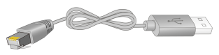
Connecting a USB-to-RJ45 console cable
|
|
IMPORTANT: · To use a USB-to-RJ45 console cable to connect the switch to a configuration terminal, first download and install the USB-to-RJ45 console driver on the configuration terminal and then connect the USB-to-RJ45 console cable to the configuration terminal. · If you have connected a USB-to-RJ45 console cable to the configuration terminal before installing the driver, remove and reconnect the USB-to-RJ45 console cable to the configuration terminal after driver installation. |
For information about the signal pinout for the RJ-45 connector of a USB-to-RJ45 console cable, see Table3-2.
The following installs the driver on the Windows system. To install the driver on other operating systems, see the installation guide in the driver compression package named by using the corresponding operating system.
To connect the switch to a configuration terminal by using a USB-to-RJ45 console cable:
1. Click the following link, or copy it to the address bar on your browser and download the USB-to-RJ45 console driver.
http://www.h3c.com/en/home/USB_to_RJ45_Console/
2. View the TXT file Read me in the Windows folder to check whether the Windows system of the configuration terminal supports the driver.
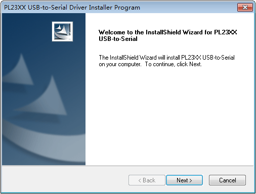
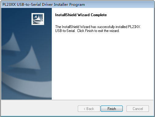
3. If the Windows system supports the driver, install PL23XX-M_LogoDriver_Setup_v200_20190815.exe.
4. Click Next on the welcome page of the driver installation wizard.
Figure3-3 Driver installation wizard
5. Click Finish after the drive installation is completed.
Figure3-4 Finishing the driver installation
6. Connect the standard USB connector of the cable to the USB port of the configuration terminal.
7. Connect the RJ-45 connector of the cable to the console port of the switch.
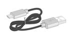
Connecting a micro USB console cable
A micro USB console cable has a micro USB connector at one end to connect to the micro USB console port of the switch, and a standard USB connector at the other end to connect to the USB port on the configuration terminal.
To connect the switch to a configuration terminal, for example a PC, by using a micro USB console cable:
1. Connect the standard USB connector to the USB port of the PC.
2. Connect the micro USB connector to the micro USB console port of the switch.
3. Click the following link, or copy it to the address bar on the browser to log in to download and install the USB console driver on the configuration terminal.
http://www.h3c.com/en/home/USB_Console/
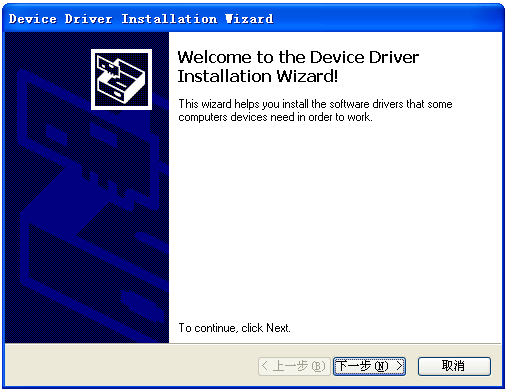
4. Select a driver program according to the operating system you use:
¡ XR21V1410_XR21B1411_Windows_Ver1840_x86_Installer.EXE—32-bit operating system.
¡ XR21V1410_XR21B1411_Windows_Ver1840_x64_Installer.EXE—64-bit operating system.
5. Click Next on the installation wizard.
Figure3-5 Device Driver Installation Wizard
6. Click Continue Anyway.
Figure3-6 Software Installation

7. Click Finish.
Figure3-7 Completing the device driver installation wizard

Setting terminal parameters
To configure and manage the switch through the console port, you must run a terminal emulator program, such as TeraTermPro, on your configuration terminal. You can use the emulator program to connect a network device, a Telnet site, or an SSH site. For more information about the terminal emulator programs, see the user guides for these programs.
Configure the terminal parameters as follows:
· Bits per second—9600.
· Data bits—8.
· Stop bits—1.
· Parity—None.
· Flow control—None.
Powering on the switch
Before powering on the switch, verify that the following conditions are met:
· The power cord is connected correctly.
· The input power voltage meets the requirement of the switch.
· The console cable is correctly connected.
· The configuration terminal (a PC, for example) has started, and its serial port settings are consistent with the console port settings on the switch.
Power on the switch. During the startup process, you can access Boot ROM menus to perform tasks such as software upgrade and file management. The Boot ROM interface and menu options differ with software versions. For more information about Boot ROM menu options, see the software-matching release notes for the device.
After the startup completes, you can access the CLI to configure the switch.
For more information about the configuration commands and CLI, see the configuration guides and command references for the switch series.
4 Setting up an IRF fabric
You can use H3C IRF technology to connect and virtualize the switches into a large virtual device called an "IRF fabric" for flattened network topology, and high availability, scalability, and manageability.
The S5120V3-EI, S5120V3-LI, and S5120V3-SI switch series can be divided into five groups. You can only use the switches in the same group to set up an IRF fabric.
Table4-1 Switch groups
|
Group |
Model |
|
Group 1 |
S5120V3-EI switch series |
|
Group 2 |
S5120V3-28P-HPWR-LI-Q, S5120V3-20P-LI, S5120V3-28P-LI, S5120V3-52P-LI, S5120V3-28P-PWR-LI, S5120V3-52P-PWR-LI |
|
Group 3 |
S5120V3-28P-HPWR-LI, S5120V3-28S-HPWR-LI, S5120V3-10P-LI, S5120V3-10P-PWR-LI, S5120V3-12TP-HPWR-LI, S5120V3-28S-LI, S5120V3-52S-LI, S5120V3-28S-PWR-LI, S5120V3-52S-PWR-LI |
|
Group 4 |
S5120V3-36F-SI, S5120V3-28P-HPWR-SI, S5120V3-54P-PWR-SI |
|
Group 5 |
S5120V3-10P-SI, S5120V3-28S-HPWR-SI-Q, S5120V3-28P-SI, S5120V3-28S-SI, S5120V3-52P-SI, S5120V3-52S-SI |
IRF fabric setup flowchart
Figure4-1 IRF fabric setup flowchart
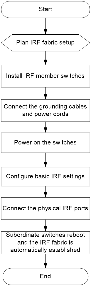
To set up an IRF fabric:
|
Step |
Description |
|
1. Plan IRF fabric setup. |
Plan the IRF fabric setup scheme based on the user network and device conditions: · Planning IRF fabric size and the installation site · Identifying the master switch and planning IRF member IDs · Planning IRF topology and connections |
|
2. Install IRF member switches. |
See "Installing the switch in a 19-inch rack", "Mounting the switch on a workbench", or "Mounting the switch on a wall." |
|
3. Connect grounding cables and power cords. |
See "Grounding the switch" and "Connecting the power cord." |
|
4. Power on the switches. |
N/A |
|
5. Configure basic IRF settings. |
See the IRF configuration guide or virtual technologies configuration guide for the switch series, depending on the software version. |
|
6. Connect the IRF physical ports. |
Connect IRF physical ports on switches. All switches except the master switch automatically reboot, and the IRF fabric is established. |
Planning IRF fabric setup
This section describes issues that an IRF fabric setup plan must cover.
Planning IRF fabric size and the installation site
Choose switch models and identify the number of required IRF member switches, depending on the user density and upstream bandwidth requirements. The switching capacity of an IRF fabric equals the total switching capacities of all member switches.
Plan the installation site depending on your network solution, as follows:
· Place all IRF member switches in one rack for centralized high-density access.
· Distribute the IRF member switches in different racks to implement the ToR access solution for a data center.
|
|
NOTE: For the maximum IRF member devices supported by the switch, see the release notes that come with the switch. |
Identifying the master switch and planning IRF member IDs
Determine which switch you want to use as the master for managing all member switches in the IRF fabric. An IRF fabric has only one master switch. You configure and manage all member switches in the IRF fabric at the CLI of the master switch. IRF member switches automatically elect a master. You can affect the election result by assigning a high member priority to the intended master switch. For more information about master election, see the IRF configuration guide or virtual technologies configuration guide for the switch series, depending on the software version.
Prepare an IRF member ID assignment scheme. An IRF fabric uses member IDs to uniquely identify and manage its members, and you must assign each IRF member switch a unique member ID.
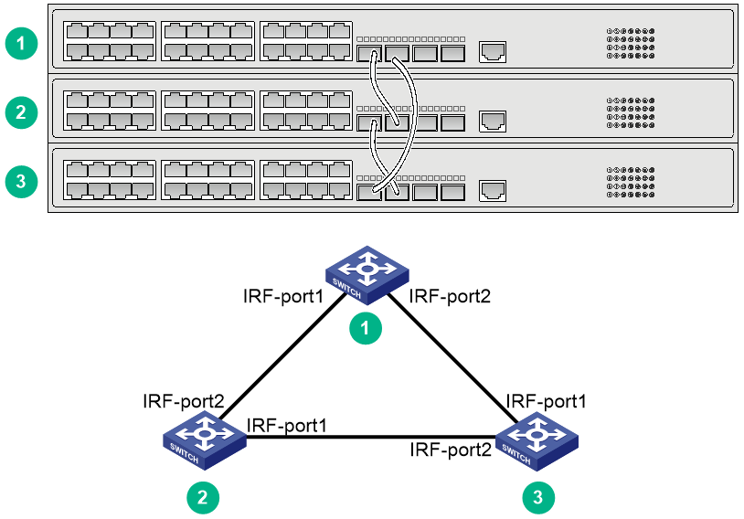
Planning IRF topology and connections
You can create an IRF fabric in daisy chain topology or more reliable ring topology. In ring topology, the failure of one IRF link does not cause the IRF fabric to split as in daisy chain topology. Instead, the IRF fabric changes to a daisy chain topology without interrupting network services.
You connect the IRF member switches through IRF ports, the logical interfaces for the connections between IRF member switches. Each IRF member switch has two IRF ports: IRF-port 1 and IRF-port 2. To use an IRF port, you must bind at least one physical port to it.
When connecting two neighboring IRF member switches, you must connect the physical ports of IRF-port 1 on one switch to the physical ports of IRF-port 2 on the other switch. See Table4-2 for the available IRF physical ports. You can bind several IRF physical ports to an IRF port for increased bandwidth and availability.
Figure4-2 and Figure4-3 show the topologies of an IRF fabric made up of three S5120V3-28S-EI switches. The IRF port connections in the two figures are for illustration only, and more connection methods are available.
Figure4-2 IRF fabric in daisy chain topology
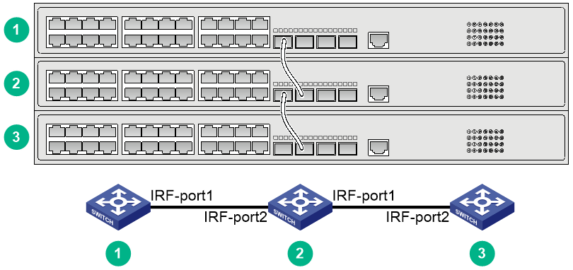
Figure4-3 IRF fabric in ring topology
Identifying IRF physical ports on the member switches
Identify the physical IRF ports on the member switches according to your topology and connection scheme.
Table4-2 shows the physical ports that can be used for IRF connection and the port use restrictions.
Table4-2 Candidate physical IRF ports and their use restrictions
|
Chassis |
Candidate physical IRF ports |
Use restrictions |
|
S5120V3-28S-EI S5120V3-54S-EI S5120V3-28S-HPWR-EI S5120V3-54S-PWR-EI |
· SFP+ ports on the front panel · 10/100/1000BASE-T autosensing Ethernet ports on the front panel |
· All physical ports to be bound to an IRF logical interface must have the same data rate. · An SFP+ port can be used as an IRF physical port only when it operates at 10 Gbps. · A 10/100/1000BASE-T autosensing Ethernet port, 1000/100BASE-T autosensing Ethernet port, or SFP port can be used as an IRF physical port only when it operates at 1 Gbps. · A 2.5G/1000/100BASE-T autosensing Ethernet port can be used as an IRF physical port only when it operates at 2.5 Gbps. · For a switch that has six SFP+ ports, use the four SFP+ ports with the highest numbers as IRF ports. For a switch that has four SFP+ ports, use the two SFP+ ports with the highest numbers as IRF ports. Using these ports as IRF ports can prevent issues such as IRF split, because IRF protocol packets from these ports can be forwarded in a queue with a higher priority. |
|
S5120V3-36F-EI S5120V3-36F-SI |
· SFP+ ports on the front panel · SFP ports on the front panel · 10/100/1000BASE-T autosensing Ethernet ports on the front panel |
|
|
S5120V3-30MS-UPWR-DP-EI |
· SFP+ ports on the front panel · 2.5G/1000/100BASE-T autosensing Ethernet ports on the front panel · 1000/100BASE-T autosensing Ethernet ports on the front panel |
|
|
S5120V3-28S-HPWR-LI |
· SFP+ ports on the front panel · SFP ports on the front panel · 10/100/1000BASE-T autosensing Ethernet ports on the front panel |
· All physical ports to be bound to an IRF logical interface must have the same data rate. · An SFP+ port can be used as an IRF physical port only when it operates at 10 Gbps. · A 10/100/1000BASE-T autosensing Ethernet port or SFP port can be used as an IRF physical port only when it operates at 1 Gbps. |
|
S5120V3-28S-LI S5120V3-52S-LI S5120V3-28S-PWR-LI S5120V3-52S-PWR-LI S5120V3-28S-SI S5120V3-52S-SI S5120V3-28S-HPWR-SI-Q |
· SFP+ ports on the front panel · 10/100/1000BASE-T autosensing Ethernet ports on the front panel |
· All physical ports to be bound to an IRF logical interface must have the same data rate. · An SFP+ port can be used as an IRF physical port only when it operates at 10 Gbps. · A 10/100/1000BASE-T autosensing Ethernet port can be used as an IRF physical port only when it operates at 1 Gbps. |
|
S5120V3-10P-SI S5120V3-28P-HPWR-SI S5120V3-54P-PWR-SI S5120V3-28P-EI S5120V3-54P-EI S5120V3-28P-HPWR-LI-Q S5120V3-10P-LI S5120V3-20P-LI S5120V3-28P-LI S5120V3-52P-LI S5120V3-10P-PWR-LI S5120V3-12TP-HPWR-LI S5120V3-28P-HPWR-LI S5120V3-28P-PWR-LI S5120V3-52P-PWR-LI S5120V3-28P-SI S5120V3-52P-SI |
· SFP ports on the front panel · 10/100/1000BASE-T autosensing Ethernet ports on the front panel |
· All physical ports to be bound to an IRF logical interface must have the same data rate. · A 10/100/1000BASE-T autosensing Ethernet port or SFP port can be used as an IRF physical port only when it operates at 1 Gbps. |
Planning the cabling scheme
Use the following cables to connect the IRF physical ports on the switches:
· 10/100/1000BASE-T autosensing Ethernet port—Category 5 or above twisted-pair cables.
· 1000/100BASE-T autosensing Ethernet port and 2.5G/1000/100BASE-T autosensing Ethernet port—Category 5e or above twisted-pair cable.
· SFP port—GE SFP fiber transceiver modules and optical fibers or GE SFP cables. For the available models, see ports in S5120V3-EI & S5120V3-LI & S5120V3-SI Switch Series Hardware Information and Specifications.
· SFP+ port—SFP+ fiber transceiver module and optical fiber or SFP+ cable. For the available transceiver models and cables, see ports in S5120V3-EI & S5120V3-LI & S5120V3-SI Switch Series Hardware Information and Specifications.
If the IRF member switches are far away from one another, use SFP/SFP+ transceiver modules and optical fibers. If the IRF member switches are all in one equipment room, use twisted pair cables or SFP/SFP+ cables.
The following subsections describe several H3C recommended IRF connection schemes by using SFP+ cables and SFP+ transceiver modules and fibers. All these schemes use a ring topology.
|
|
IMPORTANT: In these schemes, all physical IRF ports are located on the same side. If physical IRF ports are on different sides, you must calculate or measure the required cable length. |
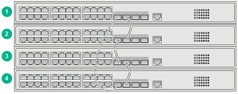
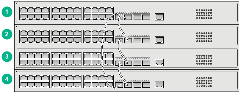
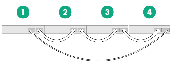
Connecting the IRF member switches in one rack
Connect the IRF member switches (four switches in this example) in a rack as shown in Figure4-4. The switches in the ring topology (see Figure4-5) are in the same order as connected in the rack.
Figure4-4 Connecting the switches in one rack

Connecting the IRF member switches in a ToR solution
You can install IRF member switches in different racks side by side to deploy a top of rack (ToR) solution.
Configuring basic IRF settings
After you install the IRF member switches, power on the switches, and log in to each IRF member switch (see the fundamentals configuration guide for the switch series) to configure their member IDs, member priorities, and IRF port bindings.
Follow these guidelines when you configure the switches:
· Assign the master switch higher member priority than any other switch.
· Bind physical ports to IRF port 1 on one switch and to IRF port 2 on the other switch. You perform IRF port binding before or after connecting IRF physical ports depending on the software release.
· Execute the display irf configuration command to verify the basic IRF settings.
For more information about configuring basic IRF settings, see the IRF configuration guide or virtual technologies configuration guide for the switch series, depending on the software version.
Connecting the IRF physical ports
Connect the IRF member switches as planned.
Wear an ESD wrist strap when you connect cables or transceiver modules and fibers. For how to connect them, see H3C Transceiver Modules and Network Cables Installation Guide.
Verifying the IRF fabric setup
To verify the basic functionality of the IRF fabric after you finish configuring basic IRF settings and connecting IRF ports:
1. Log in to the IRF fabric through the console port of any member switch.
2. Create a Layer 3 interface, assign it an IP address, and make sure the IRF fabric and the remote network management station can reach each other.
3. Use Telnet or SNMP to access the IRF fabric from the network management station. (See the fundamentals configuration guide for the switch series.)
4. Verify that you can manage all member switches as if they were one node.
5. Display the running status of the IRF fabric by using the commands in Table4-3.
Table4-3 Displaying and maintaining IRF configuration and running status
|
Task |
Command |
|
Display IRF fabric information. |
display irf |
|
Display basic IRF settings for each member device. |
display irf configuration |
|
Display IRF fabric topology information. |
display irf topology |
|
|
NOTE: To avoid IP address collision and network problems, configure a minimum of one multi-active detection (MAD) mechanism to detect the presence of multiple identical IRF fabrics and handle collisions. For more information about MAD detection, see the IRF configuration guide or virtual technologies configuration guide for the switch series, depending on the software version. |
5 Maintenance and troubleshooting
Fixed power supply failure
To identify a power failure on a switch with fixed power supplies, examine the system status LED (SYS) on the switch.
Symptom
The system status LED on the switch is off.
Solution
To resolve the issue:
1. Verify that the power receptacle on the switch is in good condition.
2. Verify that the power cord is connected correctly.
3. Verify that the power source is operating correctly.
4. Verify that the operating temperature of the switch is in the acceptable range, and the power supply has good ventilation. Overtemperature can cause the power supply to stop working and enter protection mode.
5. If the issue persists, contact H3C Support.
Removable power supply failure
The S5120V3-30MS-UPWR-DP-EI switch uses removable power supplies. You can observe the power supply status LEDs (PWR1 and PWR2) on the front panel of the switch in combination with the status LEDs on the power supplies to identify power supply failure.
For more information, see H3C PSR180-56A Power Module User Manual, H3C PSR360-56A Power Module User Manual, H3C PSR560-56D Power Module User Manual, H3C PSR720-56A Power Module User Manual, and H3C PSR1110-56A Power Module User Manual.
Symptom
A power supply LED on the front panel of the switch is not steady green.
Solution
To resolve the issue:
1. Verify that the power supply model is as required.
2. Verify that the power supply is installed securely in the switch.
3. Verify that the power cord is connected correctly.
4. Verify that the power source is operating correctly.
5. Verify that the electrical outlet is operating correctly.
6. Verify that the switch is operating in the acceptable temperature range and the power supply has good ventilation.
7. If the power supply needs to be replaced, see "Installing and removing a power supply" to replace the power supply.
8. If the issue persists, contact H3C Support.
Fan tray failure
Symptom
The system status LED on the switch indicates a fan tray failure.
Solution
When a fan tray issue occurs, contact H3C Support.
Configuration terminal issues
No display on the configuration terminal
Symptom
The configuration terminal does not have display when the switch is powered on.
Solution
To resolve the issue:
1. Verify that the power system is operating correctly.
2. Verify that the switch is operating correctly.
3. Verify that the console cable has been connected correctly.
4. Verify that the following settings are configured for the terminal:
¡ Baud rate—9600.
¡ Data bits—8.
¡ Parity—None.
¡ Stop bits—1.
¡ Flow control—None.
5. Verify that the console cable is not faulty.
6. If the issue persists, contact H3C Support.
Garbled display on the configuration terminal
Symptom
The configuration terminal displays garbled text.
Solution
To resolve the issue:
1. Verify that the following settings are configured for the terminal:
¡ Baud rate—9600.
¡ Data bits—8.
¡ Parity—None.
¡ Stop bits—1.
¡ Flow control—None.
2. If the issue persists, contact H3C Support.
