- Table of Contents
- Related Documents
-
| Title | Size | Download |
|---|---|---|
| 01-Hardware Information and Specifications | 8.63 MB |
Product models and technical specifications
S5130S-SI & S5130S-LI switch series
S5120V2-SI & S5120V2-LI switch series
S5130S-SI & S5130S-LI switch series
S5130S-28S-SI-MM & S5130S-28S-LI-MM
S5130S-28S-SI-SM & S5130S-28S-LI-SM
S5120V2-SI & S5120V2-LI switch series
S5120V2-10P-SI & S5120V2-10P-LI
S5120V2-28P-SI & S5120V2-28P-LI
S5120V2-52P-SI & S5120V2-52P-LI
10/100BASE-T autosensing Ethernet port
10/100/1000BASE-T autosensing Ethernet port
SFP port (LS-5008PV5-EI and LS-5008PV5-EI-HPWR switches)
SFP port (S5500V3-SI switch series)
SFP port (switches other than the S5008PV5-EI and S5008PV5-EI-HPWR)
SFP port LED (S5500V3-36F-DP-SI switch)
10/100BASE-T autosensing Ethernet port LED and 10/100/1000BASE-T autosensing Ethernet port LED
Product models and technical specifications
Product models
This document provides an installation guide for the following switch series:
· S5560S-SI switch series
· S5500V3-SI switch series
· S5130S-SI switch series
· S5130S-LI switch series
· S5120V2-SI switch series
· S5120V2-LI switch series
· S5110V2-SI switch series
· S5000V3-EI switch series
· S5000V5-EI switch series
· S3100V3-SI switch series
Table 1 describes the switch models that each switch series includes.
Table 1 Switch series and models
|
Switch series |
Model |
Product code (PID) |
|
|
S5560S-SI switch series |
Non-PoE models |
S5560S-28P-SI |
LS-5560S-28P-SI LS-5560S-28P-SI-GL |
|
S5560S-52P-SI |
LS-5560S-52P-SI LS-5560S-52P-SI-GL |
||
|
S5560S-28S-SI |
LS-5560S-28S-SI LS-5560S-28S-SI-GL |
||
|
S5560S-52S-SI |
LS-5560S-52S-SI LS-5560S-52S-SI-GL |
||
|
S5560S-28F-SI |
LS-5560S-28F-SI |
||
|
S5560S-28DP-SI |
LS-5560S-28DP-SI |
||
|
S5130S-SI switch series |
Non-PoE models |
S5130S-28S-SI |
LS-5130S-28S-SI |
|
S5130S-28S-SI-MM |
LS-5130S-28S-SI-MM |
||
|
S5130S-28S-SI-SM |
LS-5130S-28S-SI-SM |
||
|
S5130S-52S-SI |
LS-5130S-52S-SI |
||
|
S5130S-28F-SI |
LS-5130S-28F-SI |
||
|
S5130S-LI switch series |
Non-PoE models |
S5130S-28S-LI |
LS-5130S-28S-LI LS-5130S-28S-LI-GL |
|
S5130S-28S-LI-MM |
LS-5130S-28S-LI-MM |
||
|
S5130S-28S-LI-SM |
LS-5130S-28S-LI-SM |
||
|
S5130S-52S-LI |
LS-5130S-52S-LI LS-5130S-52S-LI-GL |
||
|
PoE models |
S5130S-28S-PWR-LI |
LS-5130S-28S-PWR-LI |
|
|
S5130S-28S-HPWR-LI |
LS-5130S-28S-HPWR-LI |
||
|
S5130S-52S-PWR-LI |
LS-5130S-52S-PWR-LI |
||
|
S5120V2-SI switch series |
Non-PoE models |
S5120V2-10P-SI |
LS-5120V2-10P-SI |
|
S5120V2-28P-SI |
LS-5120V2-28P-SI |
||
|
S5120V2-52P-SI |
LS-5120V2-52P-SI |
||
|
S5120V2-LI switch series |
Non-PoE models |
S5120V2-10P-LI |
LS-5120V2-10P-LI LS-5120V2-10P-LI-GL |
|
S5120V2-20P-LI |
LS-5120V2-20P-LI LS-5120V2-20P-LI-GL |
||
|
S5120V2-28P-LI |
LS-5120V2-28P-LI LS-5120V2-28P-LI-GL |
||
|
S5120V2-52P-LI |
LS-5120V2-52P-LI LS-5120V2-52P-LI-GL |
||
|
PoE models |
S5120V2-10P-PWR-LI |
LS-5120V2-10P-PWR-LI LS-5120V2-10P-PWR-LI-GL |
|
|
S5120V2-28P-PWR-LI |
LS-5120V2-28P-PWR-LI LS-5120V2-28P-PWR-LI-GL |
||
|
S5120V2-28P-HPWR-LI |
LS-5120V2-28P-HPWR-LI LS-5120V2-28P-HPWR-LI-GL |
||
|
S5120V2-52P-PWR-LI |
LS-5120V2-52P-PWR-LI LS-5120V2-52P-PWR-LI-GL |
||
|
S5120V2-12TP-HPWR-LI |
LS-5120V2-12TP-HPWR-LI |
||
|
S5110V2-SI switch series |
Non-PoE models |
S5110V2-28P-SI |
LS-5110V2-28P-SI |
|
S5110V2-52P-SI |
LS-5110V2-52P-SI |
||
|
S5000V3-EI switch series |
Non-PoE models |
S5016PV3-EI |
LS-5016PV3-EI LS-5016PV3-EI-GL |
|
S5024PV3-EI |
LS-5024PV3-EI LS-5024PV3-EI-GL |
||
|
S5048PV3-EI |
LS-5048PV3-EI LS-5048PV3-EI-GL |
||
|
S5024FV3-EI |
LS-5024FV3-EI LS-5024FV3-EI-GL |
||
|
PoE models |
S5024PV3-EI-PWR |
LS-5024PV3-EI-PWR LS-5024PV3-EI-PWR-GL |
|
|
S5024PV3-EI-HPWR |
LS-5024PV3-EI-HPWR LS-5024PV3-EI-HPWR-GL |
||
|
S5048PV3-EI-PWR |
LS-5048PV3-EI-PWR LS-5048PV3-EI-PWR-GL |
||
|
S5000V5-EI switch series |
Non-PoE models |
S5008PV5-EI |
LS-5008PV5-EI LS-5008PV5-EI-H1 |
|
S5008PV5-EI-S |
LS-5008PV5-EI-S-GL |
||
|
S5016PV5-EI |
LS-5016PV5-EI |
||
|
S5016PV5-EI-S |
LS-5016PV5-EI-GL |
||
|
S5024PV5-EI |
LS-5024PV5-EI LS-5024PV5-EI-GL |
||
|
S5024PV5-EI-S |
LS-5024PV5-EI-S-GL |
||
|
S5048PV5-EI |
LS-5048PV5-EI LS-5048PV5-EI-GL |
||
|
PoE models |
S5008PV5-EI-HPWR |
LS-5008PV5-EI-HPWR LS-5008PV5-EI-HPWR-H1 LS-5008PV5-EI-HPWR-GL |
|
|
S5008PV5-EI-HPWR-S |
LS-5008PV5-EI-HPWR-S-GL |
||
|
S5016PV5-EI-PWR-S |
LS-5016PV5-EI-PWR-S-GL |
||
|
S5024PV5-EI-PWR |
LS-5024PV5-EI-PWR |
||
|
S5024PV5-EI-PWR-S |
LS-5024PV5-EI-PWR-S-GL |
||
|
S5024PV5-EI-HPWR |
LS-5024PV5-EI-HPWR |
||
|
LS-5024PV5-EI-HPWR-GL |
|||
|
S5048PV5-EI-PWR |
LS-5048PV5-EI-PWR |
||
|
LS-5048PV5-EI-PWR-GL |
|||
|
S5500V3-SI switch series |
Non-PoE models |
S5500V3-24P-SI |
LS-5500V3-24P-SI |
|
S5500V3-48P-SI |
LS-5500V3-48P-SI |
||
|
S5500V3-28S-SI |
LS-5500V3-28S-SI |
||
|
S5500V3-28PS-SI |
LS-5500V3-28PS-SI |
||
|
S5500V3-54S-SI |
LS-5500V3-54S-SI |
||
|
S5500V3-54PS-SI |
LS-5500V3-54PS-SI |
||
|
S5500V3-36F-SI |
LS-5500V3-36F-SI |
||
|
S5500V3-28S-DP-SI |
LS-5500V3-28S-DP-SI |
||
|
S5500V3-54S-DP-SI |
LS-5500V3-54S-DP-SI |
||
|
S5500V3-36F-DP-SI |
LS-5500V3-36F-DP-SI |
||
|
S5500V3-54F-DP-SI |
LS-5500V3-54F-DP-SI |
||
|
S3100V3-SI switch series |
Non-PoE models |
S3100V3-10TP-SI |
LS-3100V3-10TP-SI LS-3100V3-10TP-SI-H1 |
|
S3100V3-18TP-SI |
LS-3100V3-18TP-SI LS-3100V3-18TP-SI-H1 |
||
|
S3100V3-28TP-SI |
LS-3100V3-28TP-SI LS-3100V3-28TP-SI-H1 |
||
|
S3100V3-52TP-SI |
LS-3100V3-52TP-SI LS-3100V3-52TP-SI-H1 |
||
|
PoE models |
S3100V3-10TP-PWR-SI |
LS-3100V3-10TP-PWR-SI LS-3100V3-10TP-PWR-SI-H1 |
|
|
S3100V3-20TP-PWR-SI |
LS-3100V3-20TP-PWR-SI LS-3100V3-20TP-PWR-SI-H1 |
||
|
S3100V3-28TP-PWR-SI |
LS-3100V3-28TP-PWR-SI LS-3100V3-28TP-PWR-SI-H1 |
||
|
|
NOTE: Switches of the same model but different PIDs might differ in hardware and software features. You can view the PID of a switch on the label located on its rear panel or top panel. |
Technical specifications
S5560S-SI switch series
Table 2 Technical specifications for the S5560S-SI switch series (1)
|
Item |
S5560S-28P-SI |
S5560S-52P-SI |
S5560S-28S-SI |
S5560S-52S-SI |
|
Dimensions (H × W × D) |
43.6 × 440 × 160 mm (1.72 × 17.32 × 6.30 in) |
43.6 × 440 × 230 mm (1.72 × 17.32 × 9.06 in) |
43.6 × 440 × 160 mm (1.72 × 17.32 × 6.30 in) |
43.6 × 440 × 230 mm (1.72 × 17.32 × 9.06 in) |
|
Weight |
≤ 2.5 kg (5.51 lb) |
≤ 3.5 kg (7.72 lb) |
≤ 2.5 kg (5.51 lb) |
≤ 3.5 kg (7.72 lb) |
|
Console port |
1 × serial console port |
1 × serial console port |
· 1 × micro USB console port · 1 × serial console port Only the micro USB console port is available when you connect both ports. |
· 1 × micro USB console port · 1 × serial console port Only the micro USB console port is available when you connect both ports. |
|
10/100/1000BASE-T autosensing Ethernet port |
24 |
48 |
24 |
48 |
|
SFP port |
4 |
4 |
N/A |
N/A |
|
SFP+ port |
N/A |
N/A |
4 |
4 |
|
Input voltage |
· Rated voltage: 100 VAC to 240 VAC @ 50 or 60 Hz · Max voltage: 90 VAC to 264 VAC @ 47 to 63 Hz |
|||
|
Minimum power consumption |
9 W |
18 W |
10 W |
19 W |
|
Maximum power consumption |
23 W |
41 W |
24 W |
44 W |
|
Chassis leakage current compliance |
UL 62368-1/EN 62368-1/IEC 62368-1/UL 60950-1/EN 60950-1/IEC 60950-1/GB4943.1 |
|||
|
Melting current of power supply fuse |
2 A/250 V |
3.15 A/250 V |
2 A/250 V |
3.15 A/250 V |
|
Cooling system |
Natural cooling without fan trays |
Using fixed fan trays to intake cool air from the chassis left side and right side and exhaust hot air from the chassis power supply side |
Using fixed fan trays to intake cool air from the chassis left and right sides and the port side and exhaust hot air from the power supply side |
Using fixed fan trays to intake cool air from the chassis left side and right side and exhaust hot air from the chassis power supply side |
|
Operating temperature |
–5°C to +45°C (23°F to 113°F) |
|||
|
Operating humidity |
5% RH to 95% RH, noncondensing |
|||
|
Fire resistance compliance |
UL 62368-1/EN 62368-1/IEC 62368-1/UL 60950-1/EN 60950-1/IEC 60950-1/GB4943.1 |
|||
Table 3 Technical specifications for the S5560S-SI switch series (2)
|
Item |
S5560S-28F-SI |
S5560S-28DP-SI |
|
Dimensions (H × W × D) |
43.6 × 440 × 360 mm (1.72 × 17.32 × 14.17 in) |
43.6 × 440 × 360 mm (1.72 × 17.32 × 14.17 in) |
|
Weight |
≤ 6 kg (13.23 lb) |
≤ 8 kg (17.64 lb) |
|
Console port |
· 1 × micro USB console port · 1 × serial console port Only the micro USB console port is available when you connect both ports. |
· 1 × micro USB console port · 1 × serial console port · Only the micro USB console port is available when you connect both ports. |
|
USB port |
N/A |
1 |
|
Management Ethernet port |
1 |
1 |
|
10/100/1000BASE-T autosensing Ethernet port |
8 (Each and its corresponding SFP port form a combo interface.) |
24 (The eight highest-numbered 10/100/1000BASE-T autosensing Ethernet port and their corresponding SFP ports form combo interfaces.) |
|
SFP port |
24 (The eight highest-numbered SFP ports and their corresponding 10/100/1000BASE-T autosensing Ethernet ports form combo interfaces.) |
12 (The eight highest-numbered SFP ports and their corresponding 10/100/1000BASE-T autosensing Ethernet ports form combo interfaces.) |
|
SFP+ port |
4 |
N/A |
|
Power supply slot |
2, on the rear panel |
2, on the rear panel |
|
Input voltage |
· AC input ¡ Rated voltage range: 100 VAC to 240 VAC @ 50 Hz or 60 Hz ¡ Max voltage range: 90 VAC to 290 VAC @ 47 Hz to 63 Hz · High-voltage DC input ¡ Rated voltage range: 240 VDC ¡ Max voltage range: 180 VDC to 320 VDC |
· AC input ¡ Rated voltage range: 100 VAC to 240 VAC @ 50 Hz or 60 Hz ¡ Max voltage range: 90 VAC to 290 VAC @ 47 Hz to 63 Hz · High-voltage DC input ¡ Rated voltage range: 240 VDC ¡ Max voltage range: 180 VDC to 320 VDC |
|
Minimum power consumption |
· Single PSR75-12A: 15 W · Dual PSR75-12A: 17 W |
· Single PSR75-12A: 12 W · Dual PSR75-12A: 13 W |
|
Maximum power consumption |
· Single PSR75-12A: 45 W · Dual PSR75-12A: 48 W |
· Single PSR75-12A: 29 W · Dual PSR75-12A: 32 W |
|
Chassis leakage current compliance |
UL 62368-1/EN 62368-1/IEC 62368-1/UL 60950-1/EN 60950-1/IEC 60950-1/GB4943.1 |
|
|
Melting current of power supply fuse |
3.15 A/250 V |
|
|
Cooling system |
Using fixed fan trays to intake cool air from the chassis left side and port side and exhaust hot air from the chassis right side. |
|
|
Operating temperature |
–5°C to +45°C (23°F to 113°F) |
|
|
Operating humidity |
5% RH to 95% RH, noncondensing |
|
|
Fire resistance compliance |
UL 62368-1/EN 62368-1/IEC 62368-1/UL 60950-1/EN 60950-1/IEC 60950-1/GB4943.1 |
|
S5500V3-SI switch series
Table 4 Technical specifications for S5500V3-SI switch models (1)
|
Item |
S5500V3-24P-SI |
S5500V3-48P-SI |
S5500V3-28S-SI |
S5500V3-28PS-SI |
|
Dimensions (H × W × D) |
43.6 × 440 × 160 mm (1.72 × 17.32 × 6.30 in) |
43.6 × 440 × 230 mm (1.72 × 17.32 × 9.06 in) |
43.6 × 440 × 160 mm (1.72 × 17.32 × 6.30 in) |
43.6 × 440 × 160 mm (1.72 × 17.32 × 6.30 in) |
|
Weight |
≤ 2.5 kg (5.51 lb) |
≤ 3.5 kg (7.72 lb) |
≤ 2.2 kg (4.85 lb) |
≤ 2.2 kg (4.85 lb) |
|
Console port |
· 1 × micro USB console port · 1 × serial console port Only the micro USB console port is active when you connect both ports. |
· 1 × micro USB console port · 1 × serial console port Only the micro USB console port is active when you connect both ports. |
1 × serial console port |
1 × serial console port |
|
10/100/1000BASE-T autosensing Ethernet port |
24 |
48 |
24 |
24 |
|
SFP port |
2 |
2 |
N/A |
2 |
|
SFP+ port |
2 |
2 |
4 |
2 |
|
Input voltage |
· Rated voltage: 100 VAC to 240 VAC @ 50 or 60 Hz · Max voltage: 90 VAC to 264 VAC @ 47 to 63 Hz |
|||
|
Minimum power consumption |
10 W |
19 W |
17 W |
17 W |
|
Maximum power consumption |
24 W |
44 W |
37 W |
37 W |
|
Chassis leakage current compliance |
UL 62368-1/EN 62368-1/IEC 62368-1/UL 60950-1/EN 60950-1/IEC 60950-1/GB4943.1 |
|||
|
Melting current of power supply fuse |
2 A/250 V |
3.15 A/250 V |
2 A/250 V |
2 A/250 V |
|
Cooling system |
Using fixed fan trays to intake cool air from the chassis left side, right side, and port side and exhaust hot air from the power supply side |
Using fixed fan trays to intake cool air from the chassis left side and right side and exhaust hot air from the chassis power supply side |
Left-right air aisle, intaking cool air from the chassis left side and exhausting hot air from the chassis right side |
Left-right air aisle, intaking cool air from the chassis left side and exhausting hot air from the chassis right side |
|
Operating temperature |
–5°C to +45°C (23°F to 113°F) |
|||
|
Operating humidity |
5% RH to 95% RH, noncondensing |
|||
|
Fire resistance compliance |
UL 62368-1/EN 62368-1/IEC 62368-1/UL 60950-1/EN 60950-1/IEC 60950-1/GB4943.1 |
|||
Table 5 Technical specifications for S5500V3-SI switch models (2)
|
Item |
S5500V3-54S-SI |
S5500V3-54PS-SI |
S5500V3-36F-SI |
|
|
Dimensions (H × W × D) |
43.6 × 440 × 260 mm (1.72 × 17.32 × 10.24 in) |
43.6 × 440 × 260 mm (1.72 × 17.32 × 10.24 in) |
43.6 × 440 × 260 mm (1.72 × 17.32 × 10.24 in) |
|
|
Weight |
≤ 4 kg (8.82 lb) |
≤ 4 kg (8.82 lb) |
≤ 3.5 kg (7.72 lb) |
|
|
Console port |
1 × serial console port |
|||
|
10/100/1000BASE-T autosensing Ethernet port |
48 |
48 |
8 |
|
|
SFP port |
N/A |
4 |
24 |
|
|
SFP+ port |
6 |
2 |
4 |
|
|
Input voltage |
· Rated voltage range: 100 VAC to 240 VAC @ 50 or 60 Hz · Max voltage range: 85 VAC to 264 VAC @ 47 to 63 Hz |
· Rated voltage range: 100 VAC to 240 VAC @ 50 Hz or 60 Hz · Max voltage range: 90 VAC to 264 VAC @ 47 Hz to 63 Hz |
||
|
Minimum power consumption |
19 W |
19 W |
27 W |
|
|
Maximum power consumption |
53 W |
53 W |
54 W |
|
|
Chassis leakage current compliance |
UL 62368-1/EN 62368-1/IEC 62368-1/UL 60950-1/EN 60950-1/IEC 60950-1/GB4943.1 |
|||
|
Melting current of power supply fuse |
3.15 A/250 V |
|||
|
Cooling system |
Left-right air aisle, intaking cool air from the chassis left side and exhausting hot air from the chassis right side. |
|||
|
Operating temperature |
–5°C to +45°C (23°F to 113°F) |
|||
|
Operating humidity |
5% RH to 95% RH, noncondensing |
|||
|
Fire resistance compliance |
UL 62368-1/EN 62368-1/IEC 62368-1/UL 60950-1/EN 60950-1/IEC 60950-1/GB4943.1 |
|||
Table 6 Technical specifications for S5500V3-SI switch models (3)
|
Item |
S5500V3-28S-DP-SI |
S5500V3-54S-DP-SI |
S5500V3-36F-DP-SI |
S5500V3-54F-DP-SI |
|
Dimensions (H × W × D) |
43.6 × 440 × 360 mm (1.72 × 17.32 × 14.17 in) |
43.6 × 440 × 360 mm (1.72 × 17.32 × 14.17 in) |
43.6 × 440 × 360 mm (1.72 × 17.32 × 14.17 in) |
43.6 × 440 × 360 mm (1.72 × 17.32 × 14.17 in) |
|
Weight |
≤ 5.6 kg (12.35 lb) |
≤ 6 kg (13.23 lb) |
≤ 4.5 kg (9.92 lb) |
≤ 4.5 kg (9.92 lb) |
|
Console port |
1 × serial console port |
|||
|
Management Ethernet port |
N/A |
1 |
||
|
10/100/1000BASE-T autosensing Ethernet port |
24 |
48 |
8 |
N/A |
|
SFP port |
N/A |
N/A |
24 |
48 |
|
SFP+ port |
4 |
6 |
4 |
6 |
|
Input voltage |
CA-70A12 power supply: · Rated voltage: 100 VAC to 240 VAC @ 50 or 60 Hz · Max voltage: 90 VAC to 290 VAC @ 47 to 63 Hz PSR75-12A power supply: · Rated voltage: 100 VAC to 240 VAC @ 50 or 60 Hz · Max voltage: 90 VAC to 290 VAC @ 47 to 63 Hz PSR150-D1 power supply (–48 VDC power source in the equipment room or an H3C RPS1600-A): · Rated voltage: –48 VDC to –60 VDC · Max voltage: –36 VDC to –72 VDC |
|||
|
Minimum power consumption |
· Single AC: 16 W · Single DC: 22 W · Dual AC: 18 W · Dual DC: 27 W |
· Single AC: 18 W · Single DC: 23 W · Dual AC: 23 W · Dual DC: 29 W |
· Single AC: 29 W · Single DC: 30 W · Dual AC: 35 W · Dual DC: 35 W |
· Single AC: 36 W · Single DC: 38 W · Dual AC: 43 W · Dual DC: 43 W |
|
Maximum power consumption |
· Single AC: 37 W · Single DC: 41 W · Dual AC: 39 W · Dual DC: 45 W |
· Single AC: 55 W · Single DC: 56 W · Dual AC: 57 W · Dual DC: 61 W |
· Single AC: 52 W · Single DC: 54 W · Dual AC: 58 W · Dual DC: 60 W |
· Single AC: 77 W · Single DC: 77 W · Dual AC: 80 W · Dual DC: 84 W |
|
Chassis leakage current compliance |
UL 62368-1/EN 62368-1/IEC 62368-1/UL 60950-1/EN 60950-1/IEC 60950-1/GB4943.1 |
|||
|
Melting current of power supply fuse |
· CA-70A12 power supply: 10 A/250 V · PSR75-12A power supply: 3.15 A/250 V · PSR150-D1 power supply: 8 A/250 V |
|||
|
Cooling system |
Left-right air aisle, intaking cool air from the chassis left side and exhausting hot air from the chassis right side |
|||
|
Operating temperature |
–5°C to +45°C (23°F to 113°F) |
|||
|
Operating humidity |
5% RH to 95% RH, noncondensing |
|||
|
Fire resistance compliance |
UL 62368-1/EN 62368-1/IEC 62368-1/UL 60950-1/EN 60950-1/IEC 60950-1/GB4943.1 |
|||
S5130S-SI & S5130S-LI switch series
Table 7 Technical specifications for the S5130S-SI & S5130S-LI non-PoE switch models
|
Item |
S5130S-28S-SI S5130S-28S-SI-MM S5130S-28S-SI-SM S5130S-28S-LI S5130S-28S-LI-MM S5130S-28S-LI-SM |
S5130S-52S-SI S5130S-52S-LI |
S5130S-28F-SI |
||
|
Dimensions (H × W × D) |
43.6 × 440 × 160 mm (1.72 × 17.32 × 6.30 in) |
43.6 × 440 × 230 mm (1.72 × 17.32 × 9.06 in) |
43.6 × 440 × 360 mm (1.72 × 17.32 × 14.17 in) |
||
|
Weight |
≤ 2.5 kg (5.51 lb) |
≤ 3.5 kg (7.72 lb) |
≤ 6 kg (13.23 lb) |
||
|
Console port |
· 1 × micro USB console port · 1 × serial console port Only the micro USB console port is available when you connect both ports. |
||||
|
Management Ethernet port |
N/A |
1 |
|||
|
10/100/1000BASE-T autosensing Ethernet port |
24 |
48 |
8 (Each and its corresponding SFP port form a combo interface.) |
||
|
SFP port |
N/A |
24 (The eight highest-numbered SFP ports and their corresponding 10/100/1000BASE-T autosensing Ethernet ports form combo interfaces.) |
|||
|
SFP+ port |
4 (A 10-GE SFP+ transceiver module is built into port 28 on the S5130S-28S-SI-MM, S5130S-28S-SI-SM, S5130S-28S-LI-MM, and S5130S-28S-LI-SM switches. For the built-in transceiver module specifications, see Table 36.) |
||||
|
Power supply slot |
N/A |
2, on the rear panel |
|||
|
Input voltage |
· Rated voltage: 100 VAC to 240 VAC @ 50 or 60 Hz · Max voltage: 90 VAC to 264 VAC @ 47 to 63 Hz |
· AC input ¡ Rated voltage range: 100 VAC to 240 VAC @ 50 Hz or 60 Hz ¡ Max voltage range: 90 VAC to 290 VAC @ 47 Hz to 63 Hz · High-voltage DC input ¡ Rated voltage range: 240 VDC ¡ Max voltage range: 180 VDC to 320 VDC |
|||
|
Minimum power consumption |
10 W |
19 W |
· Single PSR75-12A: 15 W · Dual PSR75-12A: 17 W |
||
|
Maximum power consumption |
24 W |
44 W |
· Single PSR75-12A: 45 W · Dual PSR75-12A: 48 W |
||
|
Chassis leakage current compliance |
UL 62368-1/EN 62368-1/IEC 62368-1/UL 60950-1/EN 60950-1/IEC 60950-1/GB4943.1 |
||||
|
Melting current of power supply fuse |
2 A/250 V |
3.15 A/250 V |
3.15 A/250 V |
||
|
Cooling system |
Using fixed fan trays to intake cool air from the chassis left and right sides and the port side and exhaust hot air from the power supply side |
Using fixed fan trays to intake cool air from the left side and right side and exhaust hot air from the power supply side |
Using fixed fan trays to intake cool air from the chassis left side and port side and exhaust hot air from the chassis right side. |
||
|
Operating temperature |
–5°C to +45°C (23°F to 113°F) |
||||
|
Operating humidity |
5% RH to 95% RH, noncondensing |
||||
|
Fire resistance compliance |
UL 62368-1/EN 62368-1/IEC 62368-1/UL 60950-1/EN 60950-1/IEC 60950-1/GB4943.1 |
||||
Table 8 Technical specifications for the S5130S-LI PoE switch models
|
Item |
S5130S-28S-PWR-LI |
S5130S-52S-PWR-LI |
S5130S-28S-HPWR-LI |
|
|
Dimensions (H × W × D) |
43.6 × 440 × 260 mm (1.72 × 17.32 ×10.24 in) |
43.6 × 440 × 400 mm (1.72 × 17.32 × 15.75 in) |
43.6 × 440 × 260 mm (1.72 × 17.32 × 10.24 in) |
|
|
Weight |
≤ 4 kg (8.82 lb) |
≤ 6 kg (13.23 lb) |
≤ 4.5 kg (9.92 lb) |
|
|
Console port |
· 1 × micro USB console port · 1 × serial console port Only the micro USB console port is available when you connect both ports. |
|||
|
10/100/1000BASE-T autosensing Ethernet port |
24 |
48 |
24 (The four highest-numbered 10/100/1000BASE-T autosensing Ethernet ports and their corresponding SFP ports form combo interfaces.) |
|
|
SFP port |
N/A |
24 (The eight highest-numbered SFP ports and their corresponding 10/100/1000BASE-T autosensing Ethernet ports form combo interfaces.) |
||
|
SFP+ port |
4 |
4 |
4 |
|
|
Input voltage |
AC input: · Rated voltage range: 100 VAC to 240 VAC @ 50 Hz or 60 Hz · Max voltage range: 90 VAC to 264 VAC @ 47 Hz to 63 Hz H3C RPS1600-A DC input (only for the S5130S-52S-PWR-LI and S5130S-28S-HPWR-LI): · Rated voltage range: –54 VDC to –57 VDC · Max voltage range: ¡ Single DC input: –44 VDC to –60 VDC ¡ DC and AC inputs: –54 VDC to –57 VDC |
|||
|
Maximum PoE power per port |
30 W |
|||
|
Total PoE power |
170 W |
AC: 370 W DC: 740 W |
AC: 370 W DC: 740 W |
|
|
Minimum power consumption |
20 W |
AC: 37 W DC: 29 W |
AC: 24 W DC: 17 W |
|
|
Maximum power consumption |
235 W |
AC: 478 W DC: 825 W |
AC: 451 W DC: 793 W |
|
|
Chassis leakage current compliance |
UL 62368-1/EN 62368-1/IEC 62368-1/UL 60950-1/EN 60950-1/IEC 60950-1/GB4943.1 |
|||
|
Melting current of power supply fuse |
10 A/250 V |
15 A/250 V |
15 A/250 V |
|
|
Cooling system |
Using fixed fan trays to intake cool air from the chassis left side and port side and exhaust hot air from the chassis right side |
Using fixed fan trays to intake cool air from the chassis left side and exhaust hot air from the chassis right side |
Using fixed fan trays to intake cool air from the chassis left side and port side and exhaust hot air from the chassis right side |
|
|
Operating temperature |
–5°C to +45°C (23°F to 113°F) |
|||
|
Operating humidity |
5% RH to 95% RH, noncondensing |
|||
|
Fire resistance compliance |
UL 62368-1/EN 62368-1/IEC 62368-1/UL 60950-1/EN 60950-1/IEC 60950-1/GB4943.1 |
|||
S5120V2-SI & S5120V2-LI switch series
Table 9 Technical specifications for the S5120V2-SI & S5120V2-LI non-PoE switch models
|
Item |
S5120V2-10P-SI S5120V2-10P-LI |
S5120V2-20P-LI |
S5120V2-28P-SI S5120V2-28P-LI |
S5120V2-52P- SI S5120V2-52P- LI |
|
|
Dimensions (H × W × D) |
43.6 × 266 × 161 mm (1.72 × 10.47 × 6.34 in) |
43.6 × 330 × 230 mm (1.72 × 12.99 × 9.06 in) |
43.6 × 440 × 160 mm (1.72 × 17.32 × 6.30 in) |
43.6 × 440 × 230 mm (1.72 × 17.32 × 9.06 in) |
|
|
Weight |
≤ 1.5 kg (3.31 lb) |
≤ 2 kg (4.41 lb) |
≤ 2.5 kg (5.51 lb) |
≤ 3.5 kg (7.72 lb) |
|
|
Console port |
1 × serial console port |
1 × serial console port |
1 × serial console port |
1 × serial console port |
|
|
10/100/1000BASE-T autosensing Ethernet port |
8 |
16 |
24 |
48 |
|
|
SFP port |
2 |
4 |
4 |
4 |
|
|
Input voltage |
· Rated voltage: 100 VAC to 240 VAC @ 50 or 60 Hz · Max voltage: 90 VAC to 264 VAC @ 47 to 63 Hz |
||||
|
Minimum power consumption |
7 W |
9 W |
9 W |
18 W |
|
|
Maximum power consumption |
12 W |
19 W |
23 W |
41 W |
|
|
Chassis leakage current compliance |
UL 62368-1/EN 62368-1/IEC 62368-1/UL 60950-1/EN 60950-1/IEC 60950-1/GB4943.1 |
||||
|
Melting current of power supply fuse |
2 A/250 V |
2 A/250 V |
2 A/250 V |
3.15 A/250 V |
|
|
Cooling system |
Natural cooling without fan trays |
Natural cooling without fan trays |
Natural cooling without fan trays |
Using fixed fan trays to intake cool air from the chassis left side and right side and exhaust hot air from the chassis power supply side |
|
|
Operating temperature |
–5°C to +45°C (23°F to 113°F) |
||||
|
Operating humidity |
5% RH to 95% RH, noncondensing |
||||
|
Fire resistance compliance |
UL 62368-1/EN 62368-1/IEC 62368-1/UL 60950-1/EN 60950-1/IEC 60950-1/GB4943.1 |
||||
Table 10 Technical specifications for S5120V2-SI & S5120V2-LI PoE switch models
|
Item |
S5120V2-10P-PWR-LI |
S5120V2-28P-PWR-LI |
S5120V2-52P-PWR-LI |
S5120V2-28P-HPWR-LI |
S5120V2-12TP-HPWR-LI |
|
Dimensions (H × W × D) |
43.6 × 330 × 230 mm (1.72 × 12.99 × 9.06 in) |
43.6 × 440 × 260 mm (1.72 × 17.32 × 10.24 in) |
43.6 × 440 × 400 mm (1.72 × 17.32 × 15.75 in) |
43.6 × 440 × 260 mm (1.72 × 17.32 × 10.24 in) |
43.6 × 330 × 230 mm (1.72 × 12.99 × 9.06 in) |
|
Weight |
≤ 3 kg (6.61 lb) |
≤ 4 kg (8.82 lb) |
≤ 6 kg (13.23 lb) |
≤ 4.5 kg (9.92 lb) |
≤ 3 kg (6.61 lb) |
|
Console port |
1 × serial console port |
1 × serial console port |
1 × serial console port |
1 × serial console port |
1 × serial console port |
|
10/100/1000BASE-T autosensing Ethernet port |
8 |
24 |
48 |
28 (The four highest-numbered 10/100/1000BASE-T autosensing Ethernet ports form combo interfaces with their corresponding SFP ports.) |
10 (The two highest-numbered 10/100/1000BASE-T autosensing Ethernet ports form combo interfaces with their corresponding SFP ports.) |
|
SFP port |
2 |
4 |
4 |
4 (Each and its corresponding 10/100/1000BASE-T autosensing Ethernet port form a combo interface.) |
4 (The two lowest-numbered SFP ports and their corresponding 10/100/1000BASE-T autosensing Ethernet port form combo interfaces.) |
|
Input voltage |
AC input: · Rated voltage: 100 VAC to 240 VAC @ 50 or 60 Hz · Max voltage: 90 VAC to 264 VAC @ 47 to 63 Hz H3C RPS1600-A DC input (only for the S5120V2-28P-HPWR-LI and S5120V2-52P-PWR-LI switches): · Rated voltage: –54 VDC to –57 VDC · Max voltage: ¡ Single DC input: –44 VDC to –60 VDC ¡ AC and DC inputs: –54 VDC to –57 VDC |
||||
|
Maximum PoE power per port |
30 W |
30 W |
30 W |
30 W The combo copper ports do not support PoE power supply. |
30 W The combo copper ports do not support PoE power supply. |
|
Total PoE power |
125 W |
170 W |
AC: 370 W DC: 740 W |
AC: 370 W DC: 740 W |
125 W |
|
Minimum power consumption |
13 W |
19 W |
AC: 36 W DC: 26 W |
AC: 23 W DC: 16 W |
14 W |
|
Maximum power consumption |
153 W |
230 W |
AC: 467 W DC: 807 W |
AC: 446 W DC: 790 W |
156 W |
|
Chassis leakage current compliance |
UL 62368-1/EN 62368-1/IEC 62368-1/UL 60950-1/EN 60950-1/IEC 60950-1/GB4943.1 |
||||
|
Melting current of power supply fuse |
6.3 A/250 V |
10 A/250 V |
15 A/250 V |
15 A/250 V |
6.3 A/250 V |
|
Cooling system |
Natural cooling without fan trays |
Using fixed fan trays to intake cool air from the chassis left side and port side and exhaust hot air from the right side |
Using fixed fan trays to intake cool air from the chassis left side and exhaust hot air from the chassis right side |
Using fixed fan trays to intake cool air from the chassis left side and port side and exhaust hot air from the chassis right side |
Natural cooling without fan trays |
|
Operating temperature |
–5°C to +45°C (23°F to 113°F) |
||||
|
Operating humidity |
5% RH to 95% RH, noncondensing |
||||
|
Fire resistance compliance |
UL 62368-1/EN 62368-1/IEC 62368-1/UL 60950-1/EN 60950-1/IEC 60950-1/GB4943.1 |
||||
S5110V2-SI switch series
Table 11 Technical specifications for the S5110V2-SI switch series
|
Item |
S5110V2-28P-SI |
S5110V2-52P-SI |
|
Dimensions (H × W × D) |
43.6 × 440 × 160 mm (1.72 × 17.32 × 6.30 in) |
43.6 × 440 × 230 mm (1.72 × 17.32 × 9.06 in) |
|
Weight |
≤ 2.5 kg (5.51 lb) |
≤ 3.5 kg (7.72 lb) |
|
Console port |
1 × serial console port |
1 × serial console port |
|
10/100/1000BASE-T autosensing Ethernet port |
24 |
48 |
|
SFP port |
4 |
4 |
|
Input voltage |
· Rated voltage: 100 VAC to 240 VAC @ 50 or 60 Hz · Max voltage: 90 VAC to 264 VAC @ 47 to 63 Hz |
|
|
Minimum power consumption |
9 W |
18 W |
|
Maximum power consumption |
23 W |
41 W |
|
Chassis leakage current compliance |
UL 62368-1/EN 62368-1/IEC 62368-1/UL 60950-1/EN 60950-1/IEC 60950-1/GB4943.1 |
|
|
Melting current of power supply fuse |
2 A/250 V |
3.15 A/250 V |
|
Cooling system |
Natural cooling without fan trays |
Using fixed fan trays to intake cool air from chassis the left side and right side and exhaust hot air from the chassis power supply side |
|
Operating temperature |
–5°C to +45°C (23°F to 113°F) |
|
|
Operating humidity |
5% RH to 95% RH, noncondensing |
|
|
Fire resistance compliance |
UL 62368-1/EN 62368-1/IEC 62368-1/UL 60950-1/EN 60950-1/IEC 60950-1/GB4943.1 |
|
S5000V3-EI switch series
Table 12 Technical specifications for the S5000V3-EI non-PoE switch models
|
Item |
S5016PV3-EI |
S5024PV3-EI |
S5048PV3-EI |
S5024FV3-EI |
|
|
Dimensions (H × W × D) |
43.6 × 330 × 230 mm (1.72 × 12.99 × 9.06 in) |
43.6 × 440 × 160 mm (1.72 × 17.32 × 6.30 in) |
43.6 × 440 × 230 mm (1.72 × 17.32 × 9.06 in)4 |
43.6 × 440 × 260 mm (1.72 × 17.32 × 10.24 in) |
|
|
Weight |
≤ 2 kg (4.41 lb) |
≤ 2.5 kg (5.51 lb) |
≤ 3.5 kg (7.72 lb) |
≤ 3 kg (6.61 lb) |
|
|
Console port |
1 × serial console port |
1 × serial console port |
1 × serial console port |
1 × serial console port |
|
|
10/100/1000BASE-T autosensing Ethernet port |
16 |
24 |
48 |
2 (Each and its corresponding SFP ports form a combo interface.) |
|
|
SFP port |
4 |
4 |
4 |
28 (SFP ports 25 and 26 form combo interfaces with their corresponding 10/100/1000BASE-T autosensing Ethernet port, respectively.) |
|
|
Input voltage |
· Rated voltage: 100 VAC to 240 VAC @ 50 or 60 Hz · Max voltage: 90 VAC to 264 VAC @ 47 to 63 Hz |
||||
|
Minimum power consumption |
9 W |
9 W |
18 W |
12 W |
|
|
Maximum power consumption |
19 W |
23 W |
41 W |
37 W |
|
|
Chassis leakage current compliance |
UL 62368-1/EN 62368-1/IEC 62368-1/UL 60950-1/EN 60950-1/IEC 60950-1/GB4943.1 |
||||
|
Melting current of power supply fuse |
2 A/250 V |
2 A/250 V |
3.15 A/250 V |
3.15 A/250 V |
|
|
Cooling system |
Natural cooling without fan trays |
Natural cooling without fan trays |
Using fixed fan trays to intake cool air from the chassis left side and right side and exhaust hot air from the chassis power supply side |
Using fixed fan trays to intake cool air from the chassis right side and port side and exhaust hot air from the power supply side |
|
|
Operating temperature |
–5°C to +45°C (23°F to 113°F) |
||||
|
Operating humidity |
5% RH to 95% RH, noncondensing |
||||
|
Fire resistance compliance |
UL 62368-1/EN 62368-1/IEC 62368-1/UL 60950-1/EN 60950-1/IEC 60950-1/GB4943.1 |
||||
Table 13 Technical specifications for S5000V3-EI PoE switch models
|
Item |
S5024PV3-EI-PWR |
S5024PV3-EI-HPWR |
S5048PV3-EI-PWR |
|
Dimensions (H × W × D) |
43.6 × 440 × 260 mm (1.72 × 17.32 × 10.24 in) |
43.6 × 440 × 260 mm (1.72 × 17.32 × 10.24 in) |
43.6 × 440 × 400 mm (1.72 × 17.32 × 15.75 in) |
|
Weight |
≤ 4 kg (8.82 lb) |
≤ 4.5 kg (9.92 lb) |
≤ 6 kg (13.23 lb) |
|
Console port |
1 × serial console port |
1 × serial console port |
1 × serial console port |
|
10/100/1000BASE-T autosensing Ethernet port |
24 |
24 |
48 |
|
SFP port |
4 |
4 |
4 |
|
Input voltage |
AC input: · Rated voltage: 100 VAC to 240 VAC @ 50 or 60 Hz · Max voltage: 90 VAC to 264 VAC @ 47 to 63 Hz H3C RPS1600-A DC input (only for the S5024PV3-EI-HPWR and S5048PV3-EI-PWR switches): · Rated voltage: –54 VDC to –57 VDC · Max voltage: ¡ Single DC input: –44 VDC to –60 VDC ¡ AC and DC inputs: –54 VDC to –57 VDC |
||
|
Maximum PoE power per port |
30 W |
30 W |
30 W |
|
Total PoE power |
170 W |
AC: 370 W DC: 740 W |
AC: 370 W DC: 740 W |
|
Minimum power consumption |
19 W |
AC: 19 W DC: 11 W |
AC: 36 W DC: 26 W |
|
Maximum power consumption |
230 W |
AC: 448 W DC: 782 W |
AC: 467 W DC: 807 W |
|
Chassis leakage current compliance |
UL 62368-1/EN 62368-1/IEC 62368-1/UL 60950-1/EN 60950-1/IEC 60950-1/GB4943.1 |
||
|
Melting current of power supply fuse |
10 A/250 V |
15 A/250 V |
15 A/250 V |
|
Cooling system |
Using fixed fan trays to intake cool air from the chassis left side and port side and exhaust hot air from the right side |
Using fixed fan trays to intake cool air from the chassis left side and port side and exhaust hot air from the chassis right side |
Using fixed fan trays to intake cool air from the chassis left side and exhaust hot air from the chassis right side |
|
Operating temperature |
–5°C to +45°C (23°F to 113°F) |
||
|
Operating humidity |
5% RH to 95% RH, noncondensing |
||
|
Fire resistance compliance |
UL 62368-1/EN 62368-1/IEC 62368-1/UL 60950-1/EN 60950-1/IEC 60950-1/GB4943.1 |
||
S5000V5-EI switch series
Table 14 Technical specifications for the S5000V5-EI non-PoE switch models (1)
|
Item |
S5008PV5-EI with product code LS-5008PV5-EI |
S5008PV5-EI with product code LS-5008PV5-EI-H1 |
S5016PV5-EI |
S5024PV5-EI |
|
Dimensions (H × W × D) |
44 × 264 × 162 mm (1.73 × 10.39 × 6.38 in) |
43.6 × 266 × 161 mm (1.72 × 10.47 × 6.34 in) |
43.6 × 330 × 230 mm (1.72 × 12.99 × 9.06 in) |
43.6 × 440 × 160 mm (1.72 × 17.32 × 6.30 in) |
|
Weight |
≤ 1 kg (2.20 lb) |
≤ 1.5 kg (3.31 lb) |
≤ 2 kg (4.41 lb) |
≤ 2.5 kg (5.51 lb) |
|
Console port |
1 × serial console port |
1 × serial console port |
1 × serial console port |
1 × serial console port |
|
10/100/1000BASE-T autosensing Ethernet port |
8 |
8 |
16 |
24 |
|
SFP port |
2 |
2 |
4 |
4 |
|
Input voltage |
· Rated voltage: 100 VAC to 240 VAC @ 50 or 60 Hz · Max voltage: 90 VAC to 264 VAC @ 47 to 63 Hz |
|||
|
Minimum power consumption |
5 W |
8 W |
9 W |
|
|
Maximum power consumption |
12 W |
14 W |
19 W |
23 W |
|
Chassis leakage current compliance |
UL 62368-1/EN 62368-1/IEC 62368-1/UL 60950-1/EN 60950-1/IEC 60950-1/GB4943.1 |
|||
|
Melting current of power supply fuse |
3.15 A/250 V |
2 A/250 V |
2 A/250 V |
2 A/250 V |
|
Cooling system |
Natural cooling without fan trays |
Natural cooling without fan trays |
Natural cooling without fan trays |
Natural cooling without fan trays |
|
Operating temperature |
–5°C to +45°C (23°F to 113°F) |
|||
|
Operating humidity |
5% RH to 95% RH, noncondensing |
|||
|
Fire resistance compliance |
UL 62368-1/EN 62368-1/IEC 62368-1/UL 60950-1/EN 60950-1/IEC 60950-1/GB4943.1 |
|||
Table 15 Technical specifications for the S5000V5-EI non-PoE switch models (2)
|
Item |
S5008PV5-EI-S |
S5016PV5-EI-S |
S5024PV5-EI-S |
S5048PV5-EI |
|
Dimensions (H × W × D) |
43.6 × 266 × 160 mm (1.72 × 10.47 × 6.30 in) |
43.6 × 330 × 230 mm (1.72 × 12.99 × 9.06 in) |
43.6 × 294 × 179 mm (1.72 × 11.57 × 7.05 in) |
43.6 × 440 × 230 mm (1.72 × 17.32 × 9.06 in) |
|
Weight |
≤ 1.5 kg (3.31 lb) |
≤ 2 kg (4.41 lb) |
≤ 1.6 kg (3.53 lb) |
≤ 3.5 kg (7.72 lb) |
|
Console port |
1 × serial console port |
1 × serial console port |
1 × serial console port |
1 × serial console port |
|
10/100/1000BASE-T autosensing Ethernet port |
8 |
16 |
24 |
48 |
|
SFP port |
2 |
4 |
4 |
4 |
|
Input voltage |
· Rated voltag: 100 VAC to 240 VAC @ 50 or 60 Hz · Max voltage: 90 VAC to 264 VAC @ 47 to 63 Hz |
|||
|
Minimum power consumption |
8 W |
9 W |
11 W |
18 W |
|
Maximum power consumption |
14 W |
19 W |
20 W |
41 W |
|
Chassis leakage current compliance |
UL 62368-1/EN 62368-1/IEC 62368-1/UL 60950-1/EN 60950-1/IEC 60950-1/GB4943.1 |
|||
|
Melting current of power supply fuse |
2 A/250 V |
2 A/250 V |
2 A/250 V |
3.15 A/250 V |
|
Cooling system |
Natural cooling without fan trays |
Natural cooling without fan trays |
Natural cooling without fan trays |
Using fixed fan trays to intake cool air from the chassis left side and right side and exhaust hot air from the chassis power supply side |
|
Operating temperature |
–5°C to +45°C (23°F to 113°F) |
|||
|
Operating humidity |
5% RH to 95% RH, noncondensing |
|||
|
Fire resistance compliance |
UL 62368-1/EN 62368-1/IEC 62368-1/UL 60950-1/EN 60950-1/IEC 60950-1/GB4943.1 |
|||
Table 16 Technical specifications for S5000V5-EI PoE switch models (1)
|
Item |
S5008PV5-EI-HPWR with product code LS-5008PV5-EI-HPWR |
S5008PV5-EI-HPWR with product code LS-5008PV5-EI-HPWR-H1 |
S5008PV5-EI-HPWR-S |
S5016PV5-EI-PWR-S |
|
Dimensions (H × W × D) |
44 × 330 × 230 mm (1.73 × 12.99 × 9.06 in) |
43.6 × 330 × 230 mm (1.72 × 12.99 × 9.06 in) |
43.6 × 266 × 160 mm (1.72 × 10.47 × 6.30 in) |
43.6 × 330 × 230 mm (1.72 × 12.99 × 9.06 in) |
|
Weight |
≤ 1.5 kg (3.31 lb) |
≤ 3 kg (6.61 lb) |
≤ 1.5 kg (3.31 lb) |
≤ 3 kg (6.61 lb) |
|
Console port |
1 × serial console port |
1 × serial console port |
1 × serial console port |
1 × serial console port |
|
10/100/1000BASE-T autosensing Ethernet port |
8 |
8 |
8 |
16 |
|
SFP port |
2 |
2 |
2 |
2 |
|
Input voltage |
· Rated voltage: 100 VAC to 240 VAC @ 50 or 60 Hz · Max voltage: 90 VAC to 264 VAC @ 47 to 63 Hz |
|||
|
Maximum PoE power per port |
30 W |
30 W |
30 W |
30 W |
|
Total PoE power |
125 W |
125 W |
125 W |
140 W |
|
Minimum power consumption |
5 W |
10 W |
12 W |
18 W |
|
Maximum power consumption |
150 W |
155 W |
160 W |
150 W |
|
Chassis leakage current compliance |
UL 62368-1/EN 62368-1/IEC 62368-1/UL 60950-1/EN 60950-1/IEC 60950-1/GB4943.1 |
|||
|
Melting current of power supply fuse |
6.3 A/250 V |
6.3 A/250 V |
6.3 A/250 V |
6.3 A/250 V |
|
Cooling system |
Natural cooling without fan trays |
Natural cooling without fan trays |
Natural cooling without fan trays |
Natural cooling without fan trays |
|
Operating temperature |
–5°C to +45°C (23°F to 113°F) |
|||
|
Operating humidity |
5% RH to 95% RH, noncondensing |
|||
|
Fire resistance compliance |
UL 62368-1/EN 62368-1/IEC 62368-1/UL 60950-1/EN 60950-1/IEC 60950-1/GB4943.1 |
|||
Table 17 Technical specifications for S5000V5-EI PoE switch models (2)
|
Item |
S5024PV5-EI-PWR |
S5024PV5-EI-PWR-S |
S5024PV5-EI-HPWR |
S5048PV5-EI-PWR |
|
Dimensions (H × W × D) |
43.6 × 440 × 260 mm (1.72 × 17.32 × 10.24 in) |
43.6 × 330 × 230 mm (1.72 × 12.992 × 9.06 in) |
43.6 × 440 × 260 mm (1.72 × 17.32 × 10.24 in) |
43.6 × 440 × 400 mm (1.72 × 17.32 × 15.75 in) |
|
Weight |
≤ 4 kg (8.82 lb) |
≤ 3 kg (6.61 lb) |
≤ 4.5 kg (9.92 lb) |
≤ 6 kg (13.23 lb) |
|
Console port |
1 × serial console port |
1 × serial console port |
1 × serial console port |
1 × serial console port |
|
10/100/1000BASE-T autosensing Ethernet port |
24 |
24 |
24 |
48 |
|
SFP port |
4 |
2 |
4 |
4 |
|
Input voltage |
· Rated voltage: 100 VAC to 240 VAC @ 50 or 60 Hz · Max voltage: 90 VAC to 264 VAC @ 47 to 63 Hz |
|||
|
Maximum PoE power per port |
30 W |
30 W |
30 W |
30 W |
|
Total PoE power |
240 W |
140 W |
370 W |
370 W |
|
Minimum power consumption |
15 W |
18 W |
19 W |
36 W |
|
Maximum power consumption |
294 W |
150 W |
448 W |
467 W |
|
Chassis leakage current compliance |
UL 62368-1/EN 62368-1/IEC 62368-1/UL 60950-1/EN 60950-1/IEC 60950-1/GB4943.1 |
|||
|
Melting current of power supply fuse |
6.3 A/250 V 10 A/250 V 15 A/250 V |
|||
|
Cooling system |
Using fixed fan trays to intake cool air from the chassis left side and port side and exhaust hot air from the chassis right side |
Natural cooling without fan trays |
Using fixed fan trays to intake cool air from the chassis left side and port side and exhaust hot air from the chassis right side |
Using fixed fan trays to intake cool air from the chassis left side and exhaust hot air from the chassis right side |
|
Operating temperature |
–5°C to +45°C (23°F to 113°F) |
|||
|
Operating humidity |
5% RH to 95% RH, noncondensing |
|||
|
Fire resistance compliance |
UL 62368-1/EN 62368-1/IEC 62368-1/UL 60950-1/EN 60950-1/IEC 60950-1/GB4943.1 |
|||
S3100V3-SI switch series
Table 18 Technical specifications for S3100V3-SI non-PoE switch models
|
Item |
S3100V3-10TP-SI |
S3100V3-18TP-SI |
S3100V3-28TP-SI |
S3100V3-52TP-SI |
|
Dimensions (H × W × D) |
43.6 × 266 × 161 mm (1.72 × 10.47 × 6.34 in) |
43.6 × 266 × 161 mm (1.72 × 10.47 × 6.34 in) |
43.6 × 440 × 160 mm (1.72 × 17.32 × 6.30 in) |
43.6 × 440 × 230 mm (1.72 × 17.32 × 9.06 in)4 |
|
Weight |
≤ 1.5 kg (3.31 lb) |
≤ 1.5 kg (3.31 lb) |
≤ 2.5 kg (5.51 lb) |
≤ 3.5 kg (7.72 lb) |
|
Console port |
1 × serial console port |
1 × serial console port |
1 × serial console port |
1 × serial console port |
|
10/100BASE-T autosensing Ethernet port |
4 |
8 |
16 |
32 |
|
10/100/1000BASE-T autosensing Ethernet port |
4 |
8 |
8 |
16 |
|
SFP port |
2 |
2 |
4 |
4 |
|
Input voltage |
· Rated voltage: 100 VAC to 240 VAC @ 50 or 60 Hz · Max voltage: 90 VAC to 264 VAC @ 47 to 63 Hz |
|||
|
Minimum power consumption |
6.5 W |
7 W |
9 W |
18 W |
|
Maximum power consumption |
11 W |
15 W |
19 W |
33 W |
|
Chassis leakage current compliance |
UL 62368-1/EN 62368-1/IEC 62368-1/UL 60950-1/EN 60950-1/IEC 60950-1/GB4943.1 |
|||
|
Melting current of power supply fuse |
2 A/250 V |
2 A/250 V |
2 A/250 V |
3.15 A/250 V |
|
Cooling system |
Natural cooling without fan trays |
Natural cooling without fan trays |
Natural cooling without fan trays |
Using fixed fan trays to intake cool air from the chassis left side and right side and exhaust hot air from the chassis power supply side |
|
Operating temperature |
–5°C to +45°C (23°F to 113°F) |
|||
|
Operating humidity |
5% RH to 95% RH, noncondensing |
|||
|
Fire resistance compliance |
UL 62368-1/EN 62368-1/IEC 62368-1/UL 60950-1/EN 60950-1/IEC 60950-1/GB4943.1 |
|||
Table 19 Technical specifications for S3100V3-EI PoE switch models
|
Item |
S3100V3-10TP-PWR-SI |
S3100V3-20TP-PWR-SI |
S3100V3-28TP-PWR-SI with product code LS-3100V3-28TP-PWR-SI) |
S3100V3-28TP-PWR-SI with product code LS-3100V3-28TP-PWR-SI-H1 |
|
Dimensions (H × W × D) |
43.6 × 330 × 230 mm (1.72 × 12.99 × 9.06 in) |
43.6 × 330 × 230 mm (1.72 × 12.99 × 9.06 in) |
43.6 × 440 × 260 mm (1.72 × 17.32 × 10.24 in) |
43.6 × 440 × 260 mm (1.72 × 17.32 × 10.24 in) |
|
Weight |
≤ 3 kg (6.61 lb) |
≤ 3 kg (6.61 lb) |
≤ 4.5 kg (9.92 lb) |
≤ 4.5 kg (9.92 lb) |
|
Console port |
1 × serial console port |
1 × serial console port |
1 × serial console port |
1 × serial console port |
|
10/100BASE-T autosensing Ethernet port |
4 |
8 |
16 |
16 |
|
10/100/1000BASE-T autosensing Ethernet port |
4 |
8 |
12 (The four highest-numbered 10/100/1000BASE-T autosensing Ethernet ports each form a combo interface with its corresponding SFP port.) |
12 (The four highest-numbered 10/100/1000BASE-T autosensing Ethernet ports each form a combo interface with its corresponding SFP port.) |
|
SFP port |
2 |
4 |
4 (Each and its corresponding 10/100/1000BASE-T autosensing Ethernet port form a combo interface.) |
4 (Each and its corresponding 10/100/1000BASE-T autosensing Ethernet port form a combo interface.) |
|
Input voltage |
AC input: · Rated voltage: 100 VAC to 240 VAC @ 50 or 60 Hz · Max voltage: 90 VAC to 264 VAC @ 47 to 63 Hz H3C RPS1600-A DC input (only for an S3100V3-28TP-PWR-SI switch with product code LS-3100V3-28TP-PWR-SI): · Rated voltage: –54 VDC to –57 VDC · Max voltage: ¡ Single DC input: –44 VDC to –60 VDC ¡ AC and DC inputs: –54 VDC to –57 VDC |
|||
|
Maximum PoE power per port |
30 W |
30 W |
30 W |
30 W |
|
Total PoE power |
125 W |
185 W |
AC: 370 W DC: 740 W |
370 W |
|
Minimum power consumption |
13 W |
Models with product code LS-3100V3-20TP-PWR-SI: 18 W Models with product code LS-3100V3-20TP-PWR-SI-H1: 15 W |
AC: 23 W DC: 16 W |
15 W |
|
Maximum power consumption |
150 W |
Models with product code LS-3100V3-20TP-PWR-SI: 220 W Models with product code LS-3100V3-20TP-PWR-SI-H1: 235 W |
AC: 439 W DC: 788 W |
443 W |
|
Chassis leakage current compliance |
UL 62368-1/EN 62368-1/IEC 62368-1/UL 60950-1/EN 60950-1/IEC 60950-1/GB4943.1 |
|||
|
Melting current of power supply fuse |
6.3 A/250 V |
6.3 A/250 V |
15 A/250 V |
15 A/250 V |
|
Cooling system |
Natural cooling without fan trays |
Using fixed fan trays to intake cool air from the chassis left side and exhaust hot air from the chassis right side |
Using fixed fan trays to intake cool air from the chassis left side and port side and exhaust hot air from the chassis right side |
Using fixed fan trays to intake cool air from the chassis left side and port side and exhaust hot air from the chassis right side |
|
Operating temperature |
–5°C to +45°C (23°F to 113°F) |
|||
|
Operating humidity |
5% RH to 95% RH, noncondensing |
|||
|
Fire resistance compliance |
UL 62368-1/EN 62368-1/IEC 62368-1/UL 60950-1/EN 60950-1/IEC 60950-1/GB4943.1 |
|||
Chassis views
S5560S-SI switch series
S5560S-28P-SI
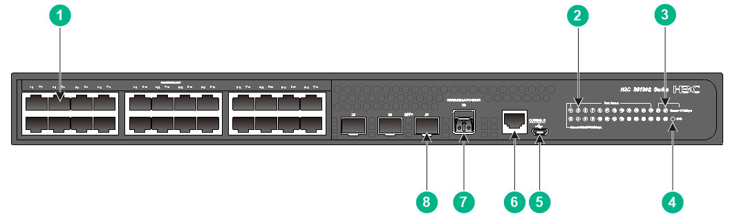
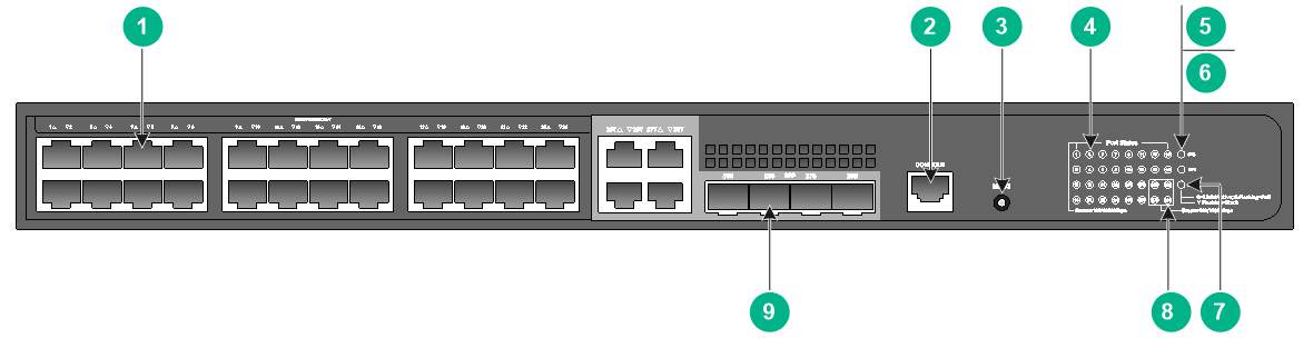
Figure 1 Front panel

|
(1) 10/100/1000BASE-T autosensing Ethernet port |
|
|
(2) 10/100/1000BASE-T autosensing Ethernet port LED |
|
|
(3) SFP port LED |
(4) System status LED (SYS) |
|
(5) Console port (CONSOLE) |
(6) SFP port |
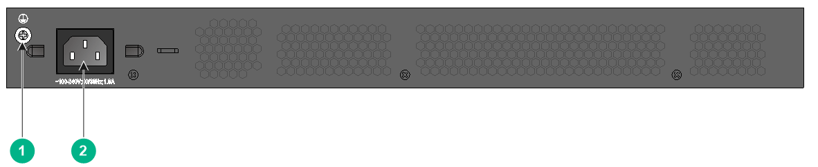
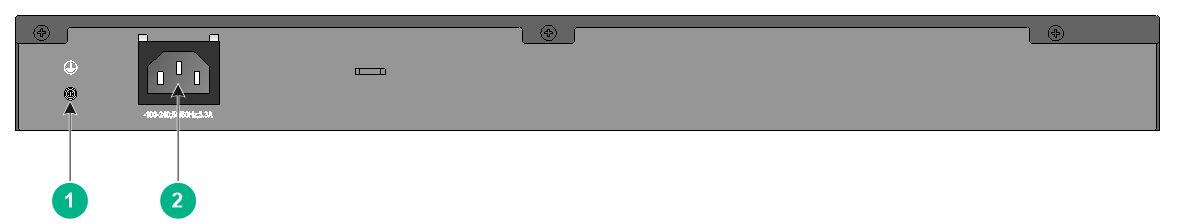
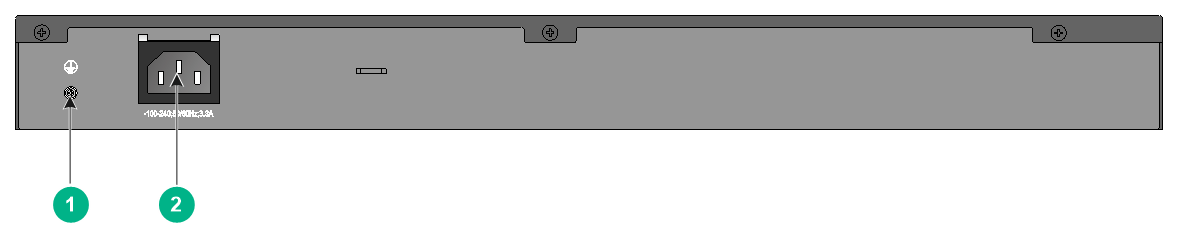
Figure 2 Rear panel

|
(1) Grounding screw |
(2) AC-input power receptacle |
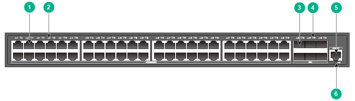
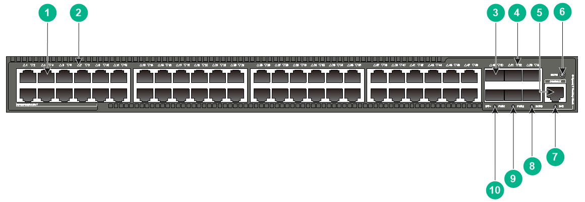
S5560S-52P-SI
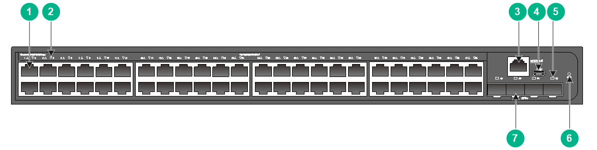
Figure 3 Front panel
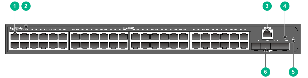
|
(1) 10/100/1000BASE-T autosensing Ethernet port |
|
|
(2) 10/100/1000BASE-T autosensing Ethernet port LED |
|
|
(3) Console port (CONSOLE) |
(4) SFP port LED |
|
(5) System status LED (SYS) |
(6) SFP port |
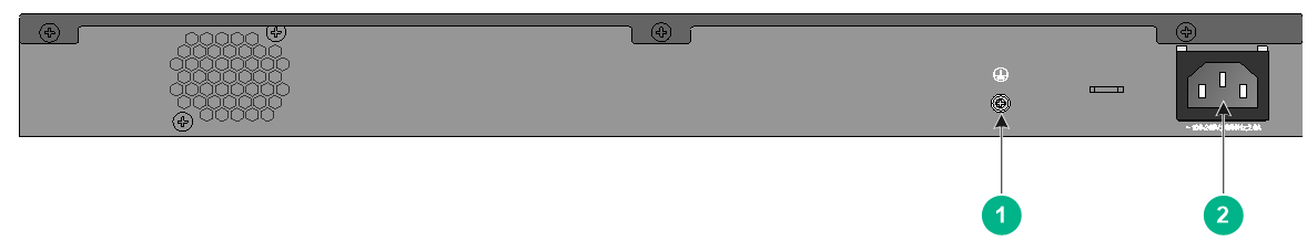
Figure 4 Rear panel

|
(1) Grounding screw |
(2) AC-input power receptacle |
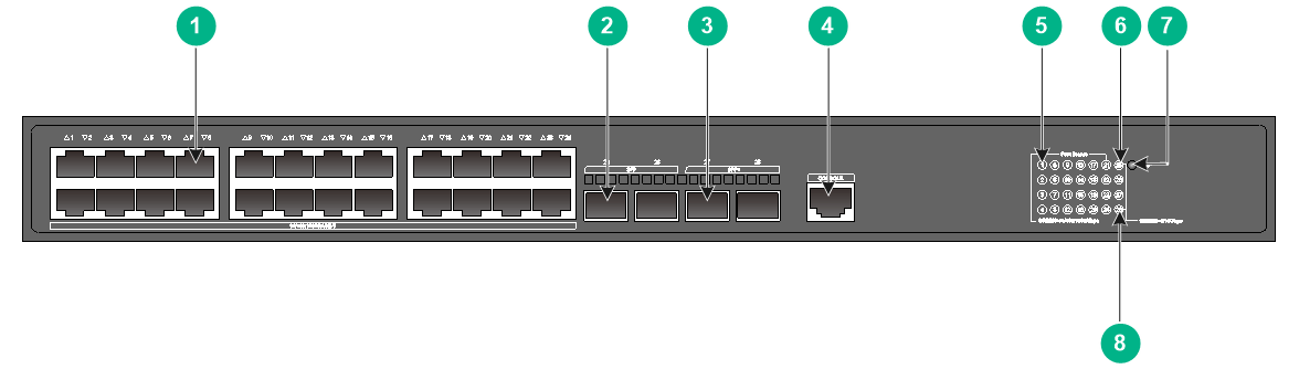
S5560S-28S-SI
Figure 5 Front panel
|
(1) 10/100/1000BASE-T autosensing Ethernet port |
|
|
(2) 10/100/1000BASE-T autosensing Ethernet port LED |
|
|
(3) SFP+ port LED |
(4) System status LED (SYS) |
|
(5) Micro USB console port |
(6) Console port (CONSOLE) |
|
(7) SFP+ port |
|
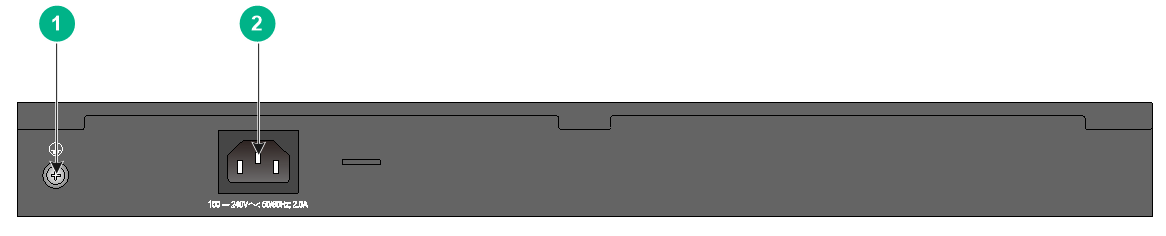
Figure 6 Rear panel

|
(1) Grounding screw |
(2) AC-input power receptacle |
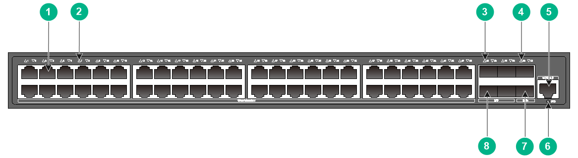
S5560S-52S-SI
Figure 7 Front panel

|
(1) 10/100/1000BASE-T autosensing Ethernet port |
|
|
(2) 10/100/1000BASE-T autosensing Ethernet port LED |
|
|
(3) Console port (CONSOLE) |
(4) Micro USB console port |
|
(5) SFP+ port LED |
(6) System status LED (SYS) |
|
(7) SFP+ port |
|
Figure 8 Rear panel

|
(1) Grounding screw |
(2) AC-input power receptacle |
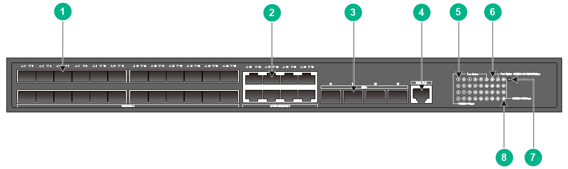
S5560S-28F-SI
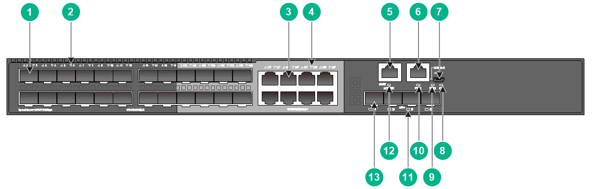
Figure 9 Front panel

|
(1) SFP port |
(2) SFP port LED |
|
(3) 10/100/1000BASE-T autosensing Ethernet port |
|
|
(4) 10/100/1000BASE-T autosensing Ethernet port LED |
|
|
(5) Management Ethernet port |
(6) Console port (CONSOLE) |
|
(7) Micro USB console port |
(8) System status LED (SYS) |
|
(9) Power supply 2 status LED (PWR2) |
(10) Power supply 1 status LED (PWR1) |
|
(11) SFP+ port LED |
(12) Management Ethernet port LED (ACT/LINK) |
|
(13) SFP+ port |
|

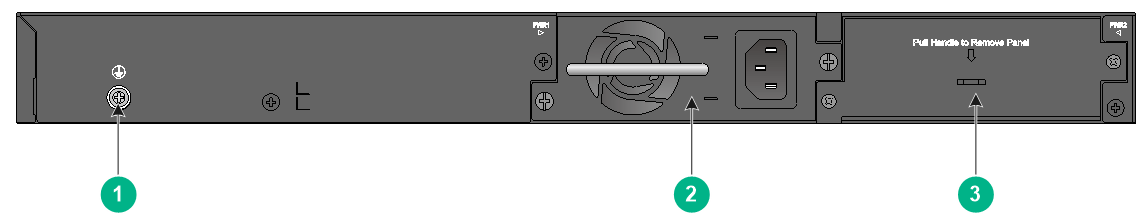
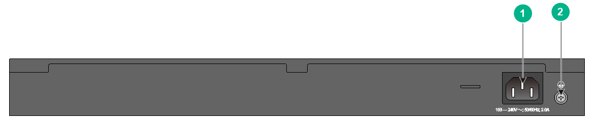
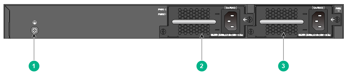
|
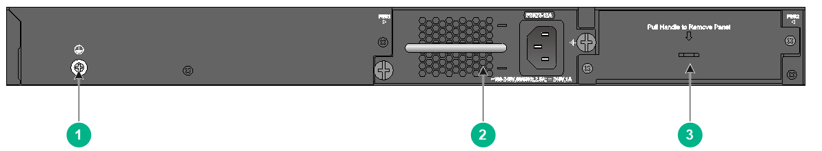
(1) Grounding screw |
(2) Power supply slot 1 (PWR1) |
|
(3) Power supply slot 2 (PWR2) |
|
An S5560S-28F-SI switch comes with power supply slot 1 installed with a PSR75-12A or CA-70A12 power supply and power supply slot 2 installed with a filler panel.
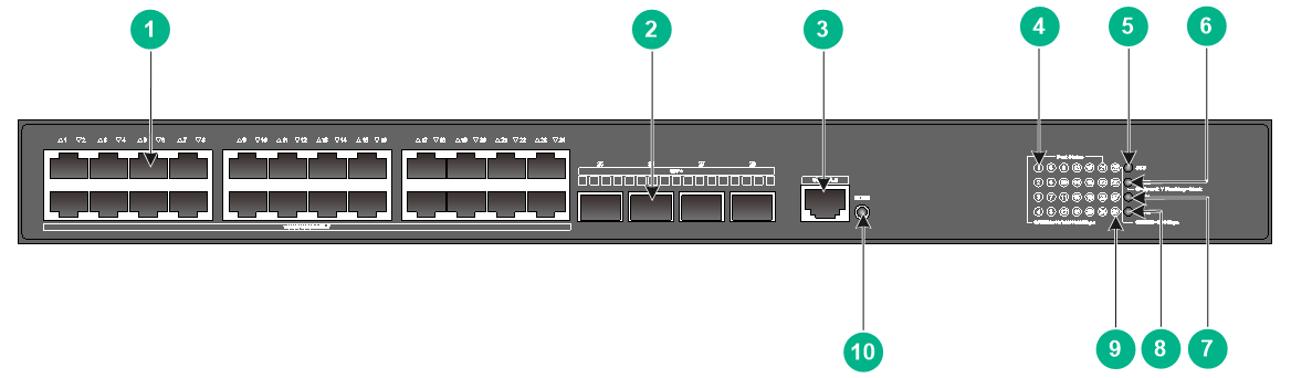
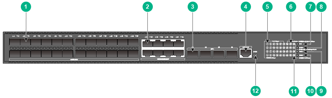
S5560S-28DP-SI
Figure 11 Front panel
|
(1) 10/100/1000BASE-T autosensing Ethernet port |
|
|
(2) 10/100/1000BASE-T autosensing Ethernet port LED |
|
|
(3) Management Ethernet port |
(4) Console port (CONSOLE) |
|
(5) Micro USB console port |
(6) Mode button |
|
(7) Mode LED (MODE) |
(8) USB port |
|
(9) System status LED (SYS) |
(10) SFP port |
|
(11) Power supply 2 status LED (PWR2) |
(12) Power supply 1 status LED (PWR1) |
|
(13) Management Ethernet port LED (ACT/LINK) |
|
|
(14) SFP port LED |
|
Figure 12 Rear panel
|
(1) Grounding screw |
(2) Power supply slot 1 (PWR1) |
|
(3) Power supply slot 2 (PWR2) |
|
An S5560S-28DP-SI switch comes with power supply slot 1 installed with a PSR75-12A or CA-70A12 power supply and power supply slot 2 installed with a filler panel.
S5500V3-SI switch series
S5500V3-24P-SI
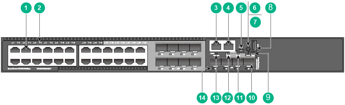
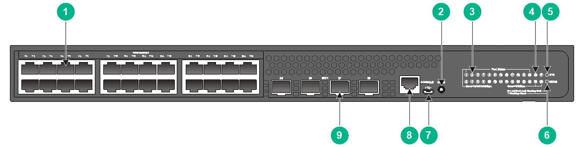
Figure 13 Front panel
|
(1) 10/100/1000BASE-T autosensing Ethernet port |
|
|
(2) 10/100/1000BASE-T autosensing Ethernet port LED |
|
|
(3) SFP+ port LED |
(4) System status LED (SYS) |
|
(5) SFP port LED |
(6) Micro USB console port |
|
(7) Console port (CONSOLE) |
(8) SFP+ port |
|
(9) SFP port |
|
Figure 14 Rear panel

|
(1) Grounding screw |
(2) AC-input power receptacle |
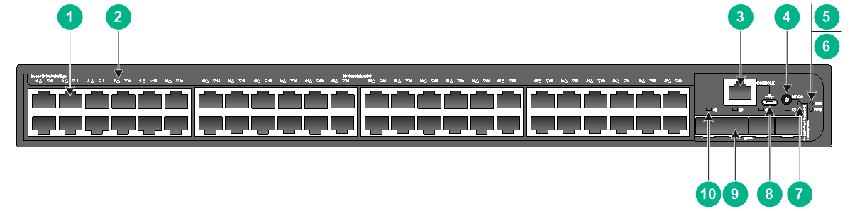
S5500V3-48P-SI
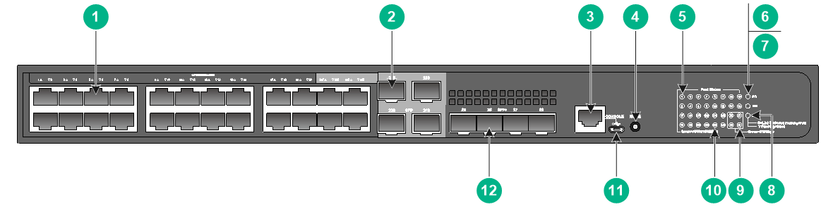
Figure 15 Front panel
|
(1) 10/100/1000BASE-T autosensing Ethernet port |
|
|
(2) 10/100/1000BASE-T autosensing Ethernet port LED |
|
|
(3) SFP port LED |
(4) Console port (CONSOLE) |
|
(5) Micro USB console port |
(6) SFP+ port LED |
|
(7) System status LED (SYS) |
(8) SFP+ port |
|
(9) SFP port |
|
Figure 16 Rear panel
|
(1) Grounding screw |
(2) AC-input power receptacle |
S5500V3-28S-SI
Figure 17 Front panel
|
(1) 10/100/1000BASE-T autosensing Ethernet port |
(2) SFP+ port |
|
(3) Console port (CONSOLE) |
|
|
(4) 10/100/1000BASE-T autosensing Ethernet port LED |
|
|
(5) System status LED (SYS) |
(6) SFP+ port LED |
Figure 18 Rear panel

|
(1) Grounding screw |
(2) AC-input power receptacle |
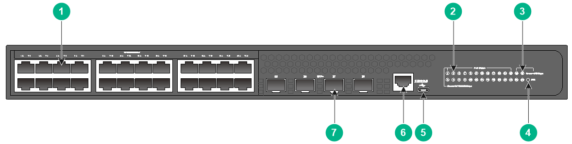
S5500V3-28PS-SI
Figure 19 Front panel
|
(1) 10/100/1000BASE-T autosensing Ethernet port |
(2) SFP port |
|
(3) SFP+ port |
(4) Console port (CONSOLE) |
|
(5) 10/100/1000BASE-T autosensing Ethernet port LED |
|
|
(6) SFP port LED |
(7) System status LED (SYS) |
|
(8) SFP+ port LED |
|
Figure 20 Rear panel
|
(1) Grounding screw |
(2) AC-input power receptacle |
S5500V3-54S-SI
Figure 21 Front panel
|
(1) 10/100/1000BASE-T autosensing Ethernet port |
|
|
(2) 10/100/1000BASE-T autosensing Ethernet port LED |
|
|
(3) SFP+ port |
(4) SFP+ port LED |
|
(5) Console port (CONSOLE) |
(6) System status LED (SYS) |
Figure 22 Rear panel

|
(1) AC-input power receptacle |
(2) Grounding screw |
S5500V3-54PS-SI
Figure 23 Front panel
|
(1) 10/100/1000BASE-T autosensing Ethernet port |
|
|
(2) 10/100/1000BASE-T autosensing Ethernet port LED |
|
|
(3) SFP port LED |
(4) SFP+ port LED |
|
(5) Console port (CONSOLE) |
(6) System status LED (SYS) |
|
(7) SFP+ port |
(8) SFP port |
Figure 24 Rear panel

|
(1) AC-input power receptacle |
(2) Grounding screw |
S5500V3-36F-SI
Figure 25 Front panel
|
(1) 1000BASE-X SFP port |
(2) 10/100/1000BASE-T autosensing Ethernet port |
|
(3) SFP+ port |
(4) Console port (CONSOLE) |
|
(5) 1000BASE-X SFP port LED |
(6) 10/100/1000BASE-T autosensing Ethernet port LED |
|
(7) System status LED (SYS) |
(8) SFP+ port LED |
Figure 26 Rear panel
|
(1) AC-input power receptacle |
(2) Grounding screw |
S5500V3-28S-DP-SI
Figure 27 Front panel
|
(1) 10/100/1000BASE-T autosensing Ethernet port |
(2) SFP+ port |
|
(3) Console port (CONSOLE) |
|
|
(4) 10/100/1000BASE-T autosensing Ethernet port LED |
|
|
(5) System status LED (SYS) |
(6) Mode LED (MODE) |
|
(7) Power supply 1 status LED (PWR1) |
(8) Power supply 2 status LED (PWR2) |
|
(9) SFP+ port LED |
(10) Mode button |

|
(1) Grounding screw |
(2) Power supply 1 |
|
(3) Power supply 2 |
|
The S5500V3-28S-DP-SI switch provides two power supply slots and comes with power supply slot 1 installed with a CA-70A12 power supply and power supply slot 2 installed with a filler panel. As shown in Figure 28, two CA-70A12 power supplies are installed in the S5500V3-28S-DP-SI switch.
S5500V3-54S-DP-SI
Figure 29 Front panel
|
(1) 10/100/1000BASE-T autosensing Ethernet port |
|
|
(2) 10/100/1000BASE-T autosensing Ethernet port LED |
|
|
(3) SFP+ port |
(4) SFP+ port LED |
|
(5) Console port (CONSOLE) |
(6) Mode button |
|
(7) System status LED (SYS) |
(8) Mode LED (MODE) |
|
(9) Power supply 2 status LED (PWR2) |
(10) Power supply 1 status LED (PWR1) |
|
(1) Grounding screw |
(2) Power supply 1 |
|
(3) Power supply 2 |
|
The S5500V3-54S-DP-SI switch provides two power supply slots and comes with power supply slot 1 installed with a CA-70A12 power supply and power supply slot 2 installed with a filler panel. As shown in Figure 30, two CA-70A12 power supplies are installed in the S5500V3-54S-DP-SI switch.
S5500V3-36F-DP-SI
Figure 31 Front panel
|
(1) 1000BASE-X SFP port |
(2) 10/100/1000BASE-T autosensing Ethernet port |
|
(3) SFP+ port |
(4) Console port (CONSOLE) |
|
(5) 1000BASE-X SFP port LED |
(6) 10/100/1000BASE-T autosensing Ethernet port LED |
|
(7) System status LED (SYS) |
(8) Mode LED (MODE) |
|
(9) Power supply 1 status LED (PWR1) |
(10) Power supply 2 status LED (PWR2) |
|
(11) SFP+ port LED |
(12) Mode button |

|
(1) Grounding screw |
(2) Power supply 1 |
|
(3) Power supply 2 |
|
The S5500V3-36F-DP-SI switch provides two power supply slots and comes with power supply slot 1 installed with a CA-70A12 power supply and power supply slot 2 installed with a filler panel. As shown in Figure 32, two CA-70A12 power supplies are installed in the S5500V3-36F-DP-SI switch.
S5500V3-54F-DP-SI
Figure 33 Front panel
|
(1) 1000BASE-X SFP port |
(2) 1000BASE-X SFP port LED |
|
(3) SFP+ port |
(4) SFP+ port LED |
|
(5) Console port (CONSOLE) |
(6) Management Ethernet port |
|
(7) System status LED (SYS) |
(8) Management Ethernet port LED |
|
(9) Power supply 2 status LED (PWR2) |
(10) Power supply 1 status LED (PWR1) |

|
(1) Grounding screw |
(2) Power supply 1 |
|
(3) Power supply 2 |
|
The S5500V3-54F-DP-SI switch provides two power supply slots and comes with power supply slot 1 installed with a CA-70A12 power supply and power supply slot 2 installed with a filler panel. As shown in Figure 34, two CA-70A12 power supplies are installed in the S5500V3-54F-DP-SI switch.
S5130S-SI & S5130S-LI switch series
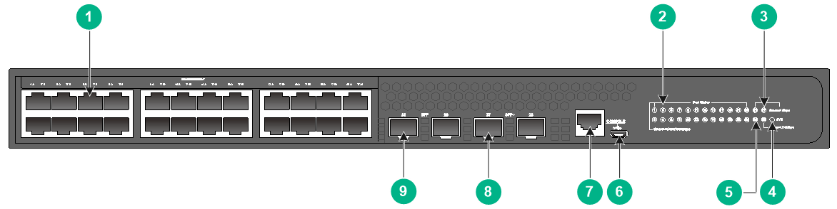
S5130S-28S-SI & S5130S-28S-LI
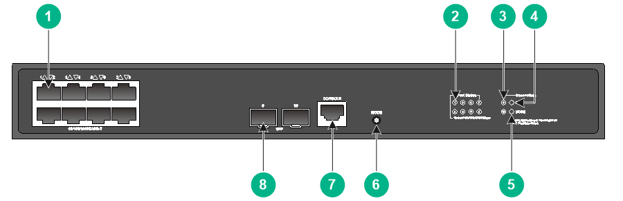
Figure 35 Front panel

|
(1) 10/100/1000BASE-T autosensing Ethernet port |
|
|
(2) 10/100/1000BASE-T autosensing Ethernet port LED |
|
|
(3) SFP+ port LED |
(4) System status LED (SYS) |
|
(5) Micro USB console port |
(6) Console port (CONSOLE) |
|
(7) SFP+ port |
|
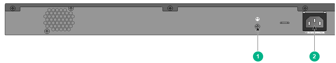
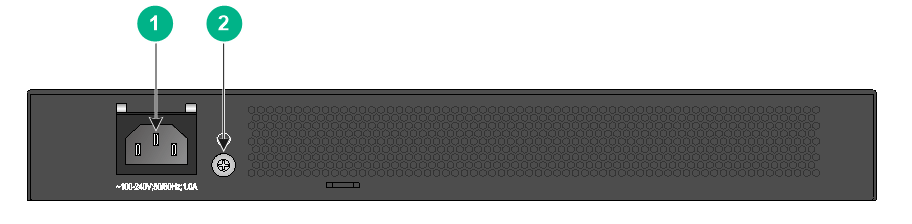
Figure 36 Rear panel

|
(1) Grounding screw |
(2) AC-input power receptacle |
S5130S-28S-SI-MM & S5130S-28S-LI-MM
Figure 37 Front panel
|
(1) 10/100/1000BASE-T autosensing Ethernet port |
|
|
(2) 10/100/1000BASE-T autosensing Ethernet port LED |
|
|
(3) SFP+ port LED |
(4) System status LED (SYS) |
|
(5) Micro USB console port |
(6) Console port (CONSOLE) |
|
(7) 10GBASE-SX-FD-MM-SR port |
(8) SFP+ port |
|
|
NOTE: A 10-GE SFP+ transceiver module is built into the 10GBASE-SX-FD-MM-SR port on the S5130S-28S-SI-MM and S5130S-28S-LI-MM switches. For the built-in transceiver module specifications, see Table 36. |
Figure 38 Rear panel

|
(1) Grounding screw |
(2) AC-input power receptacle |
S5130S-28S-SI-SM & S5130S-28S-LI-SM
Figure 39 Front panel
|
(1) 10/100/1000BASE-T autosensing Ethernet port |
|
|
(2) 10/100/1000BASE-T autosensing Ethernet port LED |
|
|
(3) SFP+ port LED |
(4) System status LED (SYS) |
|
(5) Micro USB console port |
(6) Console port (CONSOLE) |
|
(7) 10GBASE-LX-FD-SM-IR port |
(8) SFP+ port |
|
|
NOTE: A 10-GE SFP+ transceiver module is built into the 10GBASE-LX-FD-SM-IR port on the S5130S-28S-SI-SM and S5130S-28S-LI-SM switches. For the built-in transceiver module specifications, see Table 36. |
Figure 40 Rear panel
|
(1) Grounding screw |
(2) AC-input power receptacle |
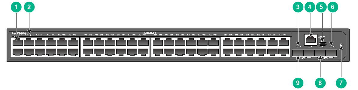
S5130S-52S-SI & S5130S-52S-LI
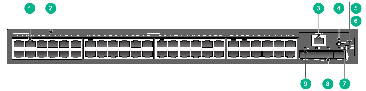
Figure 41 Front panel
|
(1) 10/100/1000BASE-T autosensing Ethernet port |
|
|
(2) 10/100/1000BASE-T autosensing Ethernet port LED |
|
|
(3) Console port (CONSOLE) |
(4) Micro USB console port |
|
(5) SFP+ port LED |
(6) System status LED (SYS) |
|
(7) SFP+ port |
|
Figure 42 Rear panel
|
(1) Grounding screw |
(2) AC-input power receptacle |
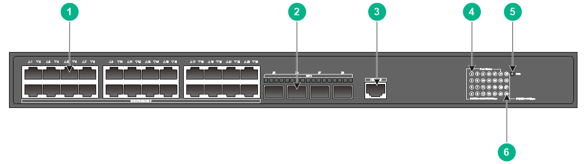
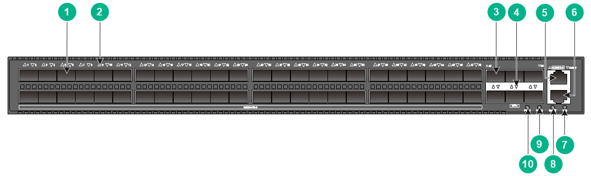
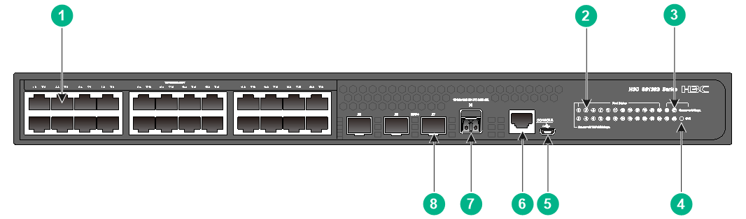
S5130S-28F-SI
Figure 43 Front panel
|
(1) SFP port |
(2) SFP port LED |
|
(3) 10/100/1000BASE-T autosensing Ethernet port |
|
|
(4) 10/100/1000BASE-T autosensing Ethernet port LED |
|
|
(5) Management Ethernet port |
(6) Console port (CONSOLE) |
|
(7) Micro USB console port |
(8) System status LED (SYS) |
|
(9) Power supply 2 status LED (PWR2) |
(10) Power supply 1 status LED (PWR1) |
|
(11) SFP+ port LED |
(12) Management Ethernet port LED (ACT/LINK) |
|
(13) SFP+ port |
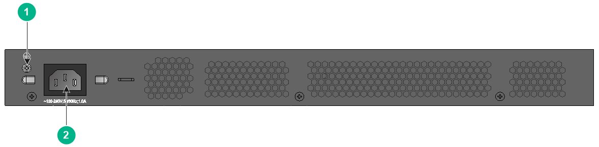
|
|
(1) Grounding screw |
(2) Power supply slot 1 (PWR1) |
|
(3) Power supply slot 2 (PWR2) |
|
An S5130S-28F-SI switch comes with power supply slot 1 installed with a PSR75-12A or CA-70A12 power supply and power supply slot 2 installed with a filler panel.
S5130S-28S-PWR-LI
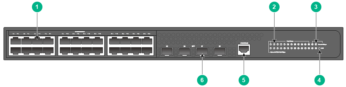
Figure 45 Front panel
|
(1) 10/100/1000BASE-T autosensing Ethernet port |
(2) Mode button |
|
(3) 10/100/1000BASE-T autosensing Ethernet port LED |
(4) SFP+ port LED |
|
(5) System status LED (SYS) |
(6) Mode LED (MODE) |
|
(7) Micro USB console port |
(8) Console port (CONSOLE) |
|
(9) SFP+ port |
|
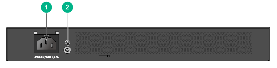
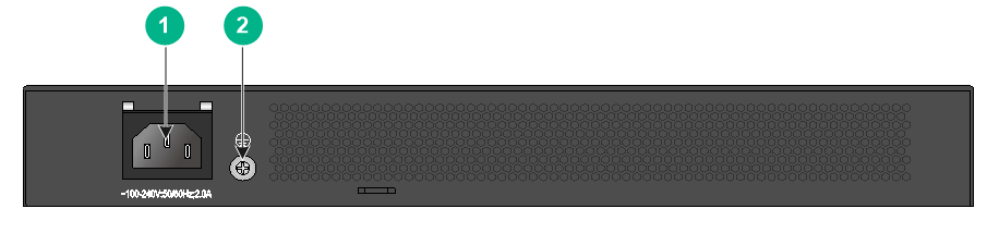
Figure 46 Rear panel

|
(1) Grounding screw |
(2) AC-input power receptacle |
S5130S-28S-HPWR-LI
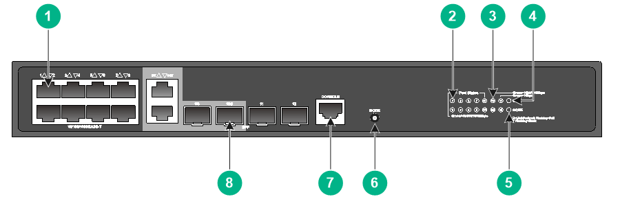
Figure 47 Front panel
|
(1) 10/100/1000BASE-T autosensing Ethernet port |
(2) SFP port |
|
(3) Console port (CONSOLE) |
(4) Mode button |
|
(5) 10/100/1000BASE-T autosensing Ethernet port LED |
(6) System status LED (SYS) |
|
(7) RPS status LED (RPS) |
(8) Mode LED (MODE) |
|
(9) SFP+ port LED |
(10) SFP port LED |
|
(11) Micro USB console port |
(12) SFP+ port |
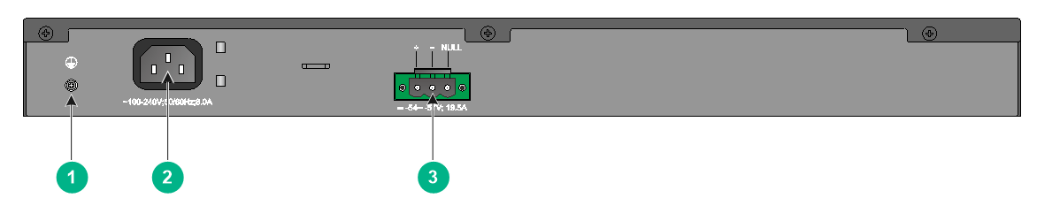
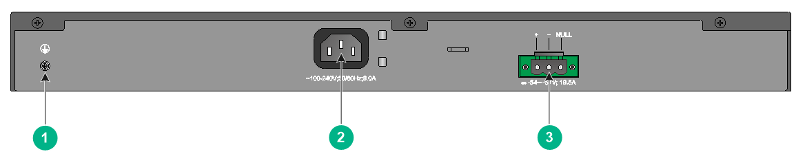
Figure 48 Rear panel

|
(1) Grounding screw |
(2) AC-input power receptacle |
|
(3) DC-input power receptacle |
|
S5130S-52S-PWR-LI
Figure 49 Front panel
|
(1) 10/100/1000BASE-T autosensing Ethernet port |
|
|
(2) 10/100/1000BASE-T autosensing Ethernet port LED |
|
|
(3) Console port (CONSOLE) |
(4) Mode button |
|
(5) System status LED (SYS) |
(6) RPS status LED (RPS) |
|
(7) Mode LED (MODE) |
(8) Micro USB console port |
|
(9) SFP+ port |
(10) SFP+ port LED |
Figure 50 Rear panel

|
(1) Grounding screw |
(2) AC-input power receptacle |
|
(3) DC-input power receptacle |
|
S5120V2-SI & S5120V2-LI switch series
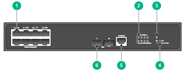
S5120V2-10P-SI & S5120V2-10P-LI
Figure 51 Front panel
|
(1) 10/100/1000BASE-T autosensing Ethernet port |
|
|
(2) 10/100/1000BASE-T autosensing Ethernet port LED |
|
|
(3) SFP port LED |
(4) System status LED (SYS) |
|
(5) Console port (CONSOLE) |
(6) SFP port |
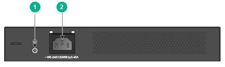
Figure 52 Rear panel
|
(1) Grounding screw |
(2) AC-input power receptacle |
S5120V2-20P-LI
Figure 53 Front panel
|
(1) 10/100/1000BASE-T autosensing Ethernet port |
|
|
(2) 10/100/1000BASE-T autosensing Ethernet port LED |
|
|
(3) SFP port LED |
(4) System status LED (SYS) |
|
(5) Console port (CONSOLE) |
(6) SFP port |
Figure 54 Rear panel
|
(1) AC-input power receptacle |
(2) Grounding screw |
S5120V2-28P-SI & S5120V2-28P-LI
Figure 55 Front panel

|
(1) 10/100/1000BASE-T autosensing Ethernet port |
|
|
(2) 10/100/1000BASE-T autosensing Ethernet port LED |
|
|
(3) SFP port LED |
(4) System status LED (SYS) |
|
(5) Console port (CONSOLE) |
(6) SFP port |
Figure 56 Rear panel
|
(1) Grounding screw |
(2) AC-input power receptacle |
S5120V2-52P-SI & S5120V2-52P-LI
Figure 57 Front panel

|
(1) 10/100/1000BASE-T autosensing Ethernet port |
|
|
(2) 10/100/1000BASE-T autosensing Ethernet port LED |
|
|
(3) Console port (CONSOLE) |
(4) SFP port LED |
|
(5) System status LED (SYS) |
(6) SFP port |
Figure 58 Rear panel

|
(1) Grounding screw |
(2) AC-input power receptacle |
S5120V2-10P-PWR-LI
Figure 59 Front panel
|
(1) 10/100/1000BASE-T autosensing Ethernet port |
|
|
(2) 10/100/1000BASE-T autosensing Ethernet port LED |
|
|
(3) SFP port LED |
(4) System status LED (SYS) |
|
(5) Mode LED (MODE) |
(6) Mode button |
|
(7) Console port (CONSOLE) |
(8) SFP port |
Figure 60 Rear panel
|
(1) AC-input power receptacle |
(2) Grounding screw |
S5120V2-28P-PWR-LI
Figure 61 Front panel

|
(1) 10/100/1000BASE-T autosensing Ethernet port |
(2) Mode button |
|
(3) 10/100/1000BASE-T autosensing Ethernet port LED |
(4) SFP port LED |
|
(5) System status LED (SYS) |
(6) Mode LED (MODE) |
|
(7) Console port (CONSOLE) |
(8) SFP port |
Figure 62 Rear panel
|
(1) Grounding screw |
(2) AC-input power receptacle |
S5120V2-28P-HPWR-LI
Figure 63 Front panel
|
(1) 10/100/1000BASE-T autosensing Ethernet port |
(2) Console port (CONSOLE) |
|
(3) Mode button |
|
|
(4) 10/100/1000BASE-T autosensing Ethernet port LED |
|
|
(5) System status LED (SYS) |
(6) RPS status LED (RPS) |
|
(7) Mode LED (MODE) |
(8) SFP port LED |
|
(9) SFP port |
|
Figure 64 Rear panel
|
(1) Grounding screw |
(2) AC-input power receptacle |
|
(3) DC-input power receptacle |
|
S5120V2-52P-PWR-LI
Figure 65 Front panel
|
(1) 10/100/1000BASE-T autosensing Ethernet port |
|
|
(2) 10/100/1000BASE-T autosensing Ethernet port LED |
|
|
(3) Console port (CONSOLE) |
(4) Mode button |
|
(5) System status LED (SYS) |
(6) RPS status LED (RPS) |
|
(7) Mode LED (MODE) |
(8) SFP port |
|
(9) SFP port LED |
|
Figure 66 Rear panel
|
(1) Grounding screw |
(2) AC-input power receptacle |
|
(3) DC-input power receptacle |
|
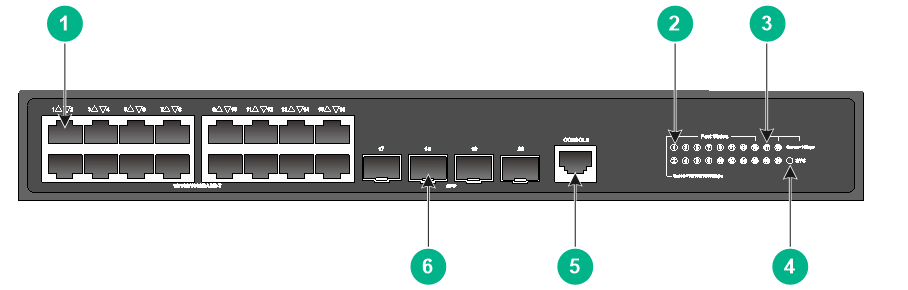
S5120V2-12TP-HPWR-LI
Figure 67 Front panel
|
(1) 10/100/1000BASE-T autosensing Ethernet port |
|
|
(2) 10/100/1000BASE-T autosensing Ethernet port LED |
|
|
(3) SFP port LED |
(4) System status LED (SYS) |
|
(5) Mode LED (MODE) |
(6) Mode button |
|
(7) Console port (CONSOLE) |
(8) SFP port |
Figure 68 Rear panel
|
(1) AC-input power receptacle |
(2) Grounding screw |
S5110V2-SI switch series
S5110V2-28P-SI
Figure 69 Front panel
|
(1) 10/100/1000BASE-T autosensing Ethernet port |
|
|
(2) 10/100/1000BASE-T autosensing Ethernet port LED |
|
|
(3) SFP port LED |
(4) System status LED (SYS) |
|
(5) Console port (CONSOLE) |
(6) SFP port |
Figure 70 Rear panel

|
(1) Grounding screw |
(2) AC-input power receptacle |
S5110V2-52P-SI
Figure 71 Front panel

|
(1) 10/100/1000BASE-T autosensing Ethernet port |
|
|
(2) 10/100/1000BASE-T autosensing Ethernet port LED |
|
|
(3) Console port (CONSOLE) |
(4) SFP port LED |
|
(5) System status LED (SYS) |
(6) SFP port |
Figure 72 Rear panel

|
(1) Grounding screw |
(2) AC-input power receptacle |
S5000V3-EI switch series
S5016PV3-EI
Figure 73 Front panel

|
(1) 10/100/1000BASE-T autosensing Ethernet port |
|
|
(2) 10/100/1000BASE-T autosensing Ethernet port LED |
|
|
(3) SFP port LED |
(4) System status LED (SYS) |
|
(5) Console port (CONSOLE) |
(6) SFP port |
Figure 74 Rear panel

|
(1) AC-input power receptacle |
(2) Grounding screw |
S5024PV3-EI
Figure 75 Front panel

|
(1) 10/100/1000BASE-T autosensing Ethernet port |
|
|
(2) 10/100/1000BASE-T autosensing Ethernet port LED |
|
|
(3) SFP port LED |
(4) System status LED (SYS) |
|
(5) Console port (CONSOLE) |
(6) SFP port |
Figure 76 Rear panel

|
(1) Grounding screw |
(2) AC-input power receptacle |
S5048PV3-EI
Figure 77 Front panel

|
(1) 10/100/1000BASE-T autosensing Ethernet port |
|
|
(2) 10/100/1000BASE-T autosensing Ethernet port LED |
|
|
(3) Console port (CONSOLE) |
(4) SFP port LED |
|
(5) System status LED (SYS) |
(6) SFP port |
Figure 78 Rear panel

|
(1) Grounding screw |
(2) AC-input power receptacle |
S5024PV3-EI-PWR
Figure 79 Front panel

|
(1) 10/100/1000BASE-T autosensing Ethernet port |
(2) Mode button |
|
(3) 10/100/1000BASE-T autosensing Ethernet port LED |
(4) SFP port LED |
|
(5) System status LED (SYS) |
(6) Mode LED (MODE) |
|
(7) Console port (CONSOLE) |
(8) SFP port |
Figure 80 Rear panel
|
(1) Grounding screw |
(2) AC-input power receptacle |
S5024PV3-EI-HPWR
Figure 81 Front panel

|
(1) 10/100/1000BASE-T autosensing Ethernet port |
(2) Mode button |
|
(3) 10/100/1000BASE-T autosensing Ethernet port LED |
(4) SFP port LED |
|
(5) System status LED (SYS) |
(6) Mode LED (MODE) |
|
(7) Console port (CONSOLE) |
(8) SFP port |
Figure 82 Rear panel
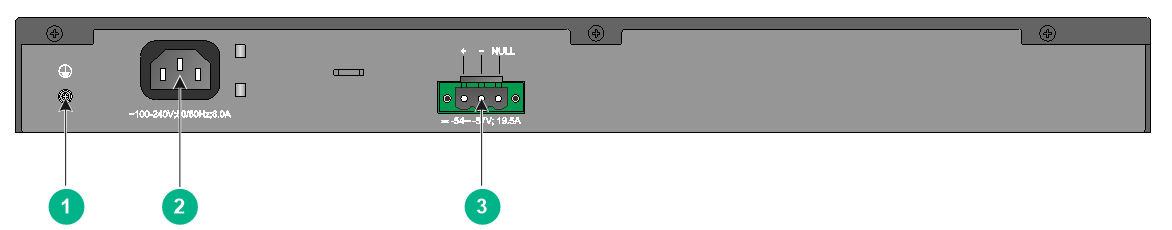
|
(1) Grounding screw |
(2) AC-input power receptacle |
|
(3) DC-input power receptacle |
|
S5048PV3-EI-PWR

|
(1) 10/100/1000BASE-T autosensing Ethernet port |
|
|
(2) 10/100/1000BASE-T autosensing Ethernet port LED |
|
|
(3) Console port (CONSOLE) |
(4) Mode button |
|
(5) System status LED (SYS) |
(6) RPS status LED (RPS) |
|
(7) Mode LED (MODE) |
(8) SFP port |
|
(9) SFP port LED |
|
Figure 84 Rear panel

|
(1) Grounding screw |
(2) AC-input power receptacle |
|
(3) DC-input power receptacle |
|
S5024FV3-EI
Figure 85 Front panel
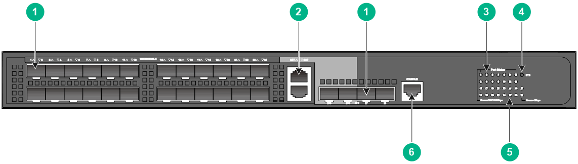
|
(1) SFP port |
(2) 10/100/1000BASE-T autosensing Ethernet port |
|
(3) SFP port LED |
(4) System status LED (SYS) |
|
(5) 10/100/1000BASE-T autosensing Ethernet port LED |
|
|
(6) Console port (CONSOLE) |
|
Figure 86 Rear panel
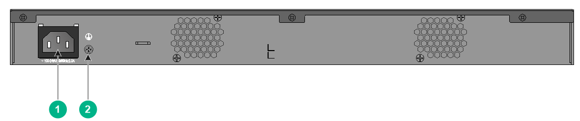
|
(1) AC-input power receptacle |
(2) Grounding screw |
S5000V5-EI switch series
S5008PV5-EI
Figure 87 Front panel (product code LS-5008PV5-EI)

|
(1) 10/100/1000BASE-T copper port |
(2) 100/1000BASE-X SFP port |
|
(3) Console port (CONSOLE) |
(4) Port status LED |
|
(5) Power status LED (Power) |
|
Figure 88 Front panel (product code LS-5008PV5-EI-H1)
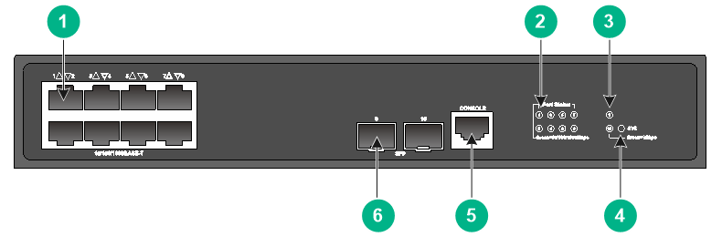
|
(1) 10/100/1000BASE-T autosensing Ethernet port |
|
|
(2) 10/100/1000BASE-T autosensing Ethernet port LED |
|
|
(3) SFP port LED |
(4) System status LED (SYS) |
|
(5) Console port (CONSOLE) |
(6) SFP port |
Figure 89 Rear panel (product code LS-5008PV5-EI)

|
(1) Grounding screw |
(2) AC-input power receptacle |
|
(3) Security slot |
|
Figure 90 Rear panel (product code LS-5008PV5-EI-H1)

|
(1) Grounding screw |
(2) AC-input power receptacle |
S5008PV5-EI-S
Figure 91 Front panel

|
(1) 10/100/1000BASE-T autosensing Ethernet port |
|
|
(2) 10/100/1000BASE-T autosensing Ethernet port LED |
|
|
(3) SFP port LED |
(4) System status LED (SYS) |
|
(5) Console port (CONSOLE) |
(6) SFP port |
Figure 92 Rear panel
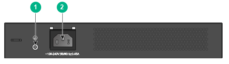
|
(1) Grounding screw |
(2) AC-input power receptacle |
S5016PV5-EI
Figure 93 Front panel
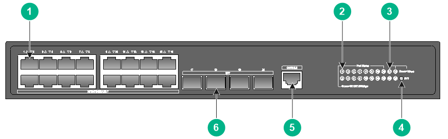
|
(1) 10/100/1000BASE-T autosensing Ethernet port |
|
|
(2) 10/100/1000BASE-T autosensing Ethernet port LED |
|
|
(3) SFP port LED |
(4) System status LED (SYS) |
|
(5) Console port (CONSOLE) |
(6) SFP port |
Figure 94 Rear panel
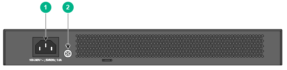
|
(1) AC-input power receptacle |
(2) Grounding screw |
S5016PV5-EI-S
Figure 95 Front panel
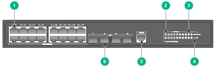
|
(1) 10/100/1000BASE-T autosensing Ethernet port |
|
|
(2) 10/100/1000BASE-T autosensing Ethernet port LED |
|
|
(3) SFP port LED |
(4) System status LED (SYS) |
|
(5) Console port (CONSOLE) |
(6) SFP port |
Figure 96 Rear panel

|
(1) AC-input power receptacle |
(2) Grounding screw |
S5024PV5-EI
Figure 97 Front panel

|
(1) 10/100/1000BASE-T autosensing Ethernet port |
|
|
(2) 10/100/1000BASE-T autosensing Ethernet port LED |
|
|
(3) SFP port LED |
(4) System status LED (SYS) |
|
(5) Console port (CONSOLE) |
(6) SFP port |
Figure 98 Rear panel

|
(1) Grounding screw |
(2) AC-input power receptacle |
S5024PV5-EI-S
Figure 99 Front panel
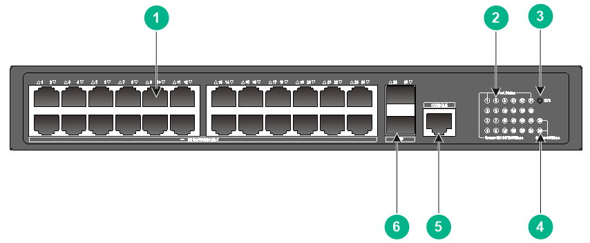
|
(1) 10/100/1000BASE-T autosensing Ethernet port |
|
|
(2) 10/100/1000BASE-T autosensing Ethernet port LED |
|
|
(3) System status LED (SYS) |
(4) SFP port LED |
|
(5) Console port (CONSOLE) |
(6) SFP port |
Figure 100 Rear panel
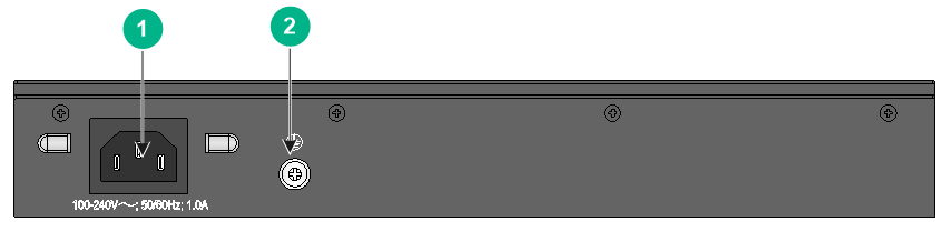
|
(1) AC-input power receptacle |
(2) Grounding screw |
S5048PV5-EI
Figure 101 Front panel
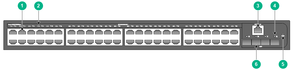
|
(1) 10/100/1000BASE-T autosensing Ethernet port |
|
|
(2) 10/100/1000BASE-T autosensing Ethernet port LED |
|
|
(3) Console port (CONSOLE) |
(4) SFP port LED |
|
(5) System status LED (SYS) |
(6) SFP port |
Figure 102 Rear panel

|
(1) Grounding screw |
(2) AC-input power receptacle |
S5008PV5-EI-HPWR
Figure 103 Front panel (product code LS-5008PV5-EI-HPWR)
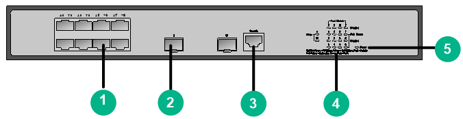
|
(1) 10/100/1000BASE-T copper port |
(2) 100/1000BASE-X SFP port |
|
(3) Console port (CONSOLE) |
(4) Port status LED |
|
(5) Power status LED (Power) |
|
Figure 104 Front panel (product code LS-5008PV5-EI-HPWR-H1)
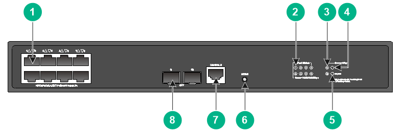
|
(1) 10/100/1000BASE-T autosensing Ethernet port |
||
|
(2) 10/100/1000BASE-T autosensing Ethernet port LED |
||
|
(3) SFP port LED |
(4) System status LED (SYS) |
|
|
(5) Mode LED (MODE) |
(6) Port LED mode switching button |
|
|
(7) Console port (CONSOLE) |
(8) SFP port |
|
Figure 105 Rear panel (product code LS-5008PV5-EI-HPWR)
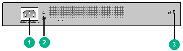
|
(1) AC-input power receptacle |
(2) Grounding screw |
|
(3) Security slot |
|
Figure 106 Rear panel (product code LS-5008PV5-EI-HPWR-H1)

|
(1) AC-input power receptacle |
(2) Grounding screw |
S5008PV5-EI-HPWR-S
Figure 107 Front panel
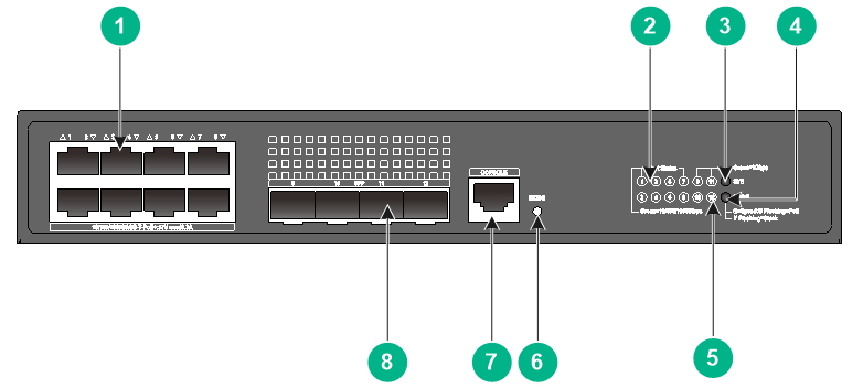
|
(1) 10/100/1000BASE-T autosensing Ethernet port |
||
|
(2) 10/100/1000BASE-T autosensing Ethernet port LED |
||
|
(3) System status LED (SYS) |
(4) Mode LED (MODE) |
|
|
(5) SFP port LED |
(6) Port LED mode switching button |
|
|
(7) Console port (CONSOLE) |
(8) SFP port |
|
Figure 108 Rear panel

|
(1) AC-input power receptacle |
(2) Grounding screw |
S5016PV5-EI-PWR-S
Figure 109 Front panel
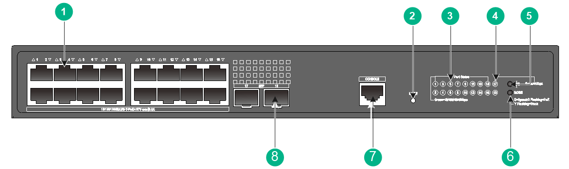
|
(1) 10/100/1000BASE-T autosensing Ethernet port |
|
|
(2) Port LED mode switching button |
|
|
(3) 10/100/1000BASE-T autosensing Ethernet port LED |
|
|
(4) SFP port LED |
(5) System status LED (SYS) |
|
(6) Mode LED (MODE) |
(7) Console port |
|
(7) SFP port |
|
Figure 110 Rear panel
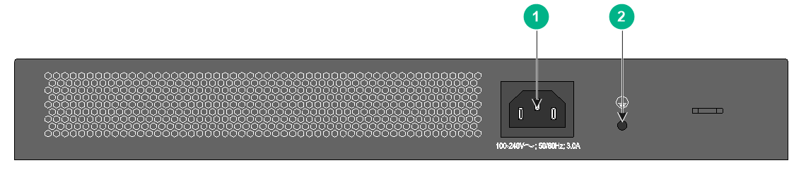
|
(1) AC-input power receptacle |
(2) Grounding screw |
S5024PV5-EI-PWR
Figure 111 Front panel

|
(1) 10/100/1000BASE-T autosensing Ethernet port |
(2) Mode button |
|
(3) 10/100/1000BASE-T autosensing Ethernet port LED |
(4) SFP port LED |
|
(5) System status LED (SYS) |
(6) Mode LED (MODE) |
|
(7) Console port (CONSOLE) |
(8) SFP port |
Figure 112 Rear panel
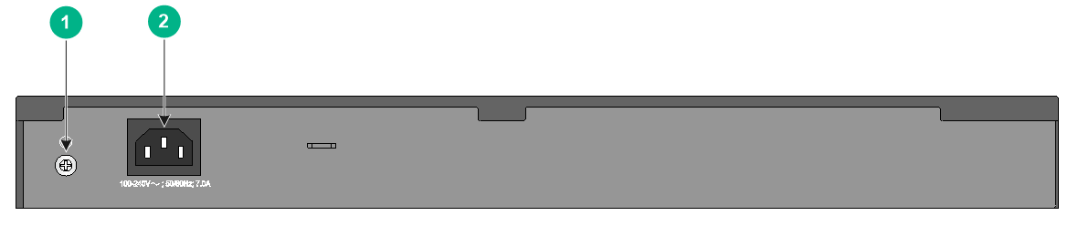
|
(1) Grounding screw |
(2) AC-input power receptacle |
S5024PV5-EI-PWR-S
Figure 113 Front panel
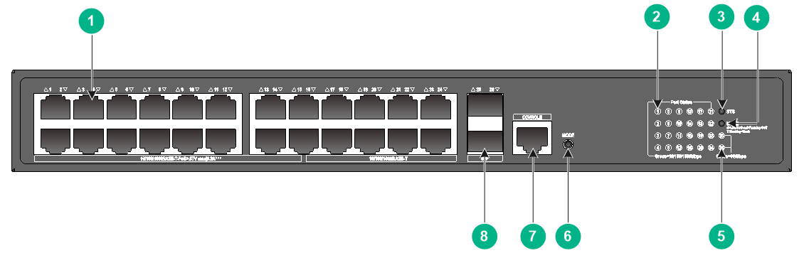
|
(1) 10/100/1000BASE-T autosensing Ethernet port |
||
|
(2) 10/100/1000BASE-T autosensing Ethernet port LED |
||
|
(3) System status LED (SYS) |
(4) Mode LED (MODE) |
|
|
(5) SFP port LED |
(6) Port LED mode switching button |
|
|
(7) Console port (CONSOLE) |
(8) SFP port |
|
Figure 114 Rear panel
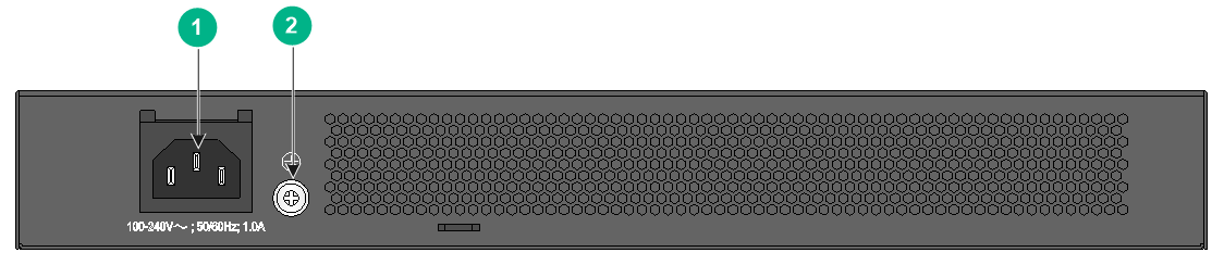
|
(1) Grounding screw |
(2) AC-input power receptacle |
S5024PV5-EI-HPWR
Figure 115 Front panel
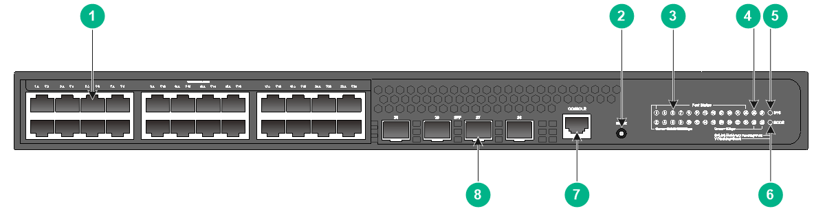
|
(1) 10/100/1000BASE-T autosensing Ethernet port |
(2) Mode button |
|
(3) 10/100/1000BASE-T autosensing Ethernet port LED |
(4) SFP port LED |
|
(5) System status LED (SYS) |
(6) Mode LED (MODE) |
|
(7) Console port (CONSOLE) |
(8) SFP port |
Figure 116 Rear panel
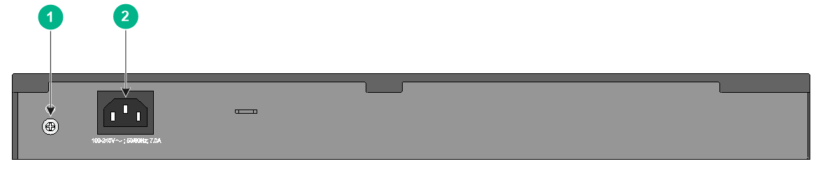
|
(1) Grounding screw |
(2) AC-input power receptacle |
S5048PV5-EI-PWR
Figure 117 Front panel
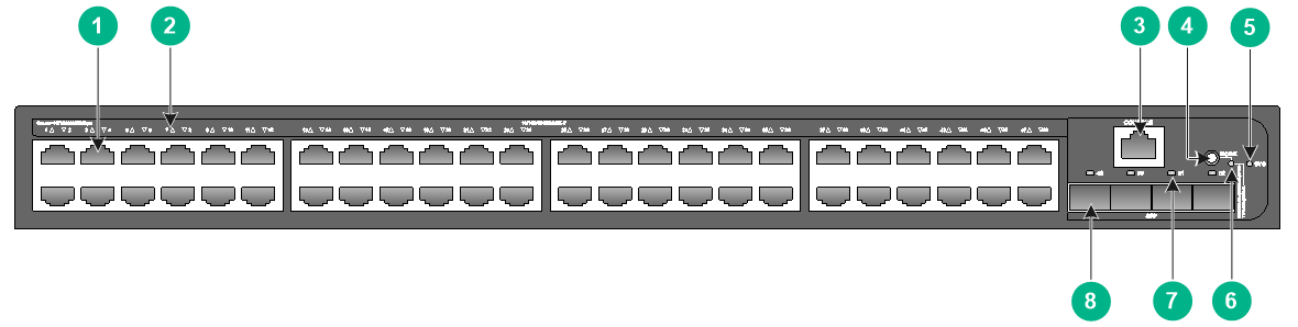
|
(1) 10/100/1000BASE-T autosensing Ethernet port |
|
|
(2) 10/100/1000BASE-T autosensing Ethernet port LED |
|
|
(3) Console port (CONSOLE) |
(4) Mode button |
|
(5) System status LED (SYS) |
(6) Mode LED (MODE) |
|
(7) SFP port LED |
(8) SFP port |
Figure 118 Rear panel
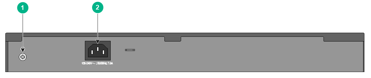
|
(1) Grounding screw |
(2) AC-input power receptacle |
S3100V3-SI switch series
S3100V3-10TP-SI
Figure 119 Front panel
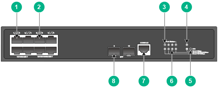
|
(1) 10/100BASE-T autosensing Ethernet port |
(2) 10/100/1000BASE-T autosensing Ethernet port |
|
(3) 10/100BASE-T autosensing Ethernet port LED |
(4) SFP port LED |
|
(5) System status LED (SYS) |
|
|
(6) 10/100/1000BASE-T autosensing Ethernet port LED |
|
|
(7) Console port (CONSOLE) |
(8) SFP port |
Figure 120 Rear panel
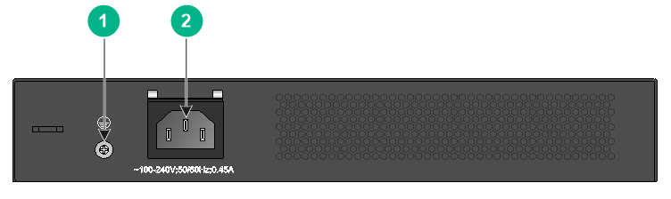
|
(1) Grounding screw |
(2) AC-input power receptacle |
S3100V3-18TP-SI
Figure 121 Front panel
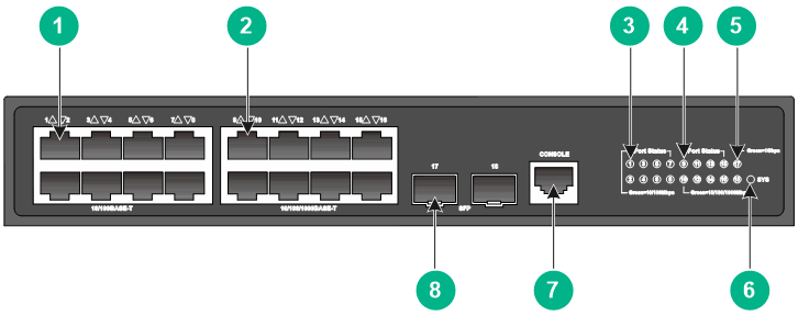
|
(1) 10/100BASE-T autosensing Ethernet port |
(2) 10/100/1000BASE-T autosensing Ethernet port |
|
(3) 10/100BASE-T autosensing Ethernet port LED |
|
|
(4) 10/100/1000BASE-T autosensing Ethernet port LED |
|
|
(5) SFP port LED |
(6) System status LED (SYS) |
|
(7) Console port (CONSOLE) |
(8) SFP port |
Figure 122 Rear panel
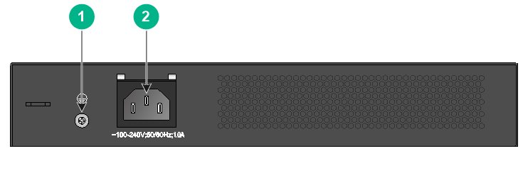
|
(1) Grounding screw |
(2) AC-input power receptacle |
S3100V3-28TP-SI
Figure 123 Front panel
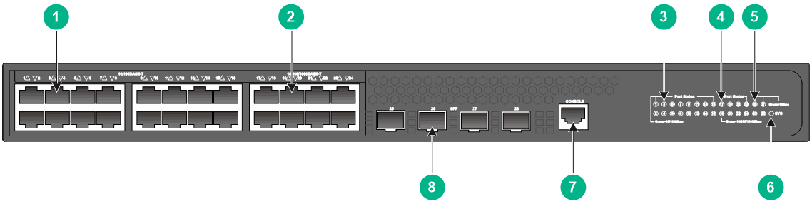
|
(1) 10/100BASE-T autosensing Ethernet port |
(2) 10/100/1000BASE-T autosensing Ethernet port |
|
(3) 10/100BASE-T autosensing Ethernet port LED |
|
|
(4) 10/100/1000BASE-T autosensing Ethernet port LED |
|
|
(5) SFP port LED |
(6) System status LED (SYS) |
|
(7) Console port (CONSOLE) |
(8) SFP port |
Figure 124 Rear panel
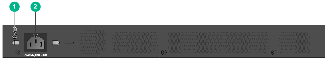
|
(1) Grounding screw |
(2) AC-input power receptacle |
S3100V3-52TP-SI
Figure 125 Front panel
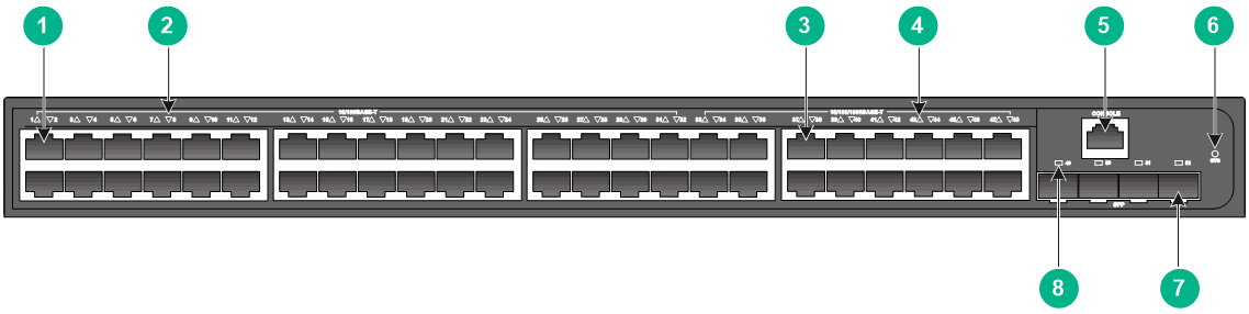
|
(1) 10/100BASE-T autosensing Ethernet port |
(2) 10/100BASE-T autosensing Ethernet port LED |
|
(3) 10/100/1000BASE-T autosensing Ethernet port |
|
|
(4) 10/100/1000BASE-T autosensing Ethernet port LED |
|
|
(5) Console port (CONSOLE) |
(6) System status LED (SYS) |
|
(7) SFP port |
(8) SFP port LED |
Figure 126 Rear panel
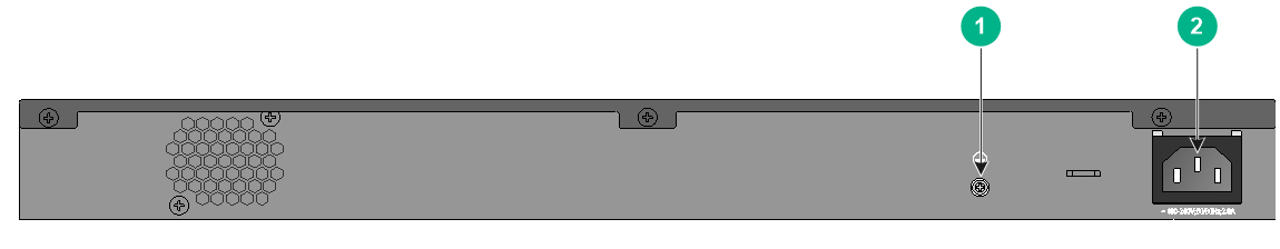
|
(1) Grounding screw |
(2) AC-input power receptacle |
S3100V3-10TP-PWR-SI
Figure 127 Front panel
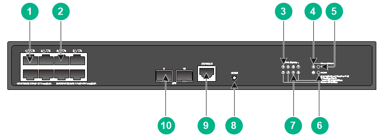
|
(1) 10/100BASE-T autosensing Ethernet port |
|
|
(2) 10/100/1000BASE-T autosensing Ethernet port |
|
|
(3) 10/100BASE-T autosensing Ethernet port LED |
(4) SFP port LED |
|
(5) System status LED (SYS) |
(6) Mode LED (MODE) |
|
(7) 10/100/1000BASE-T autosensing Ethernet port LED |
(8) Mode button |
|
(9) Console port (CONSOLE) |
(10) SFP port |
Figure 128 Rear panel
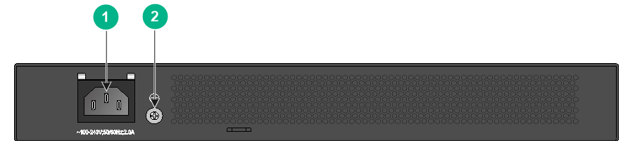
|
(1) AC-input power receptacle |
(2) Grounding screw |
S3100V3-20TP-PWR-SI
Figure 129 Front panel
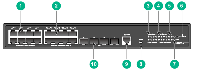
|
(1) 10/100BASE-T autosensing Ethernet port |
(2) 10/100/1000BASE-T autosensing Ethernet port |
|
(3) 10/100BASE-T autosensing Ethernet port LED |
|
|
(4) 10/100/1000BASE-T autosensing Ethernet port LED |
|
|
(5) SFP port LED |
(6) System status LED (SYS) |
|
(7) Mode LED (MODE) |
(8) Mode button |
|
(9) Console port (CONSOLE) |
(10) SFP port |
Figure 130 Rear panel
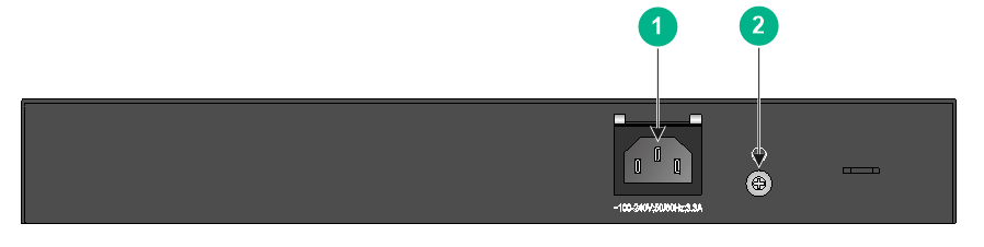
|
(1) AC-input power receptacle |
(2) Grounding screw |
S3100V3-28TP-PWR-SI
Figure 131 Front panel (product code LS-3100V3-28TP-PWR-SI)
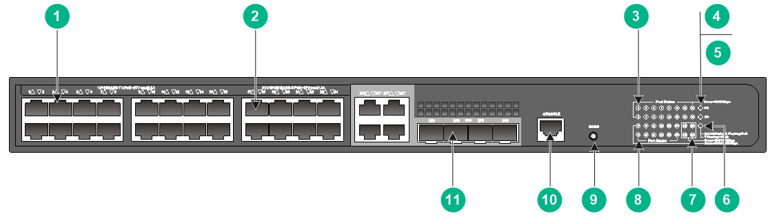
|
(1) 10/100BASE-T autosensing Ethernet port |
(2) 10/100/1000BASE-T autosensing Ethernet port |
|
(3) 10/100BASE-T autosensing Ethernet port LED |
(4) System status LED (SYS) |
|
(5) RPS status LED (RPS) |
(6) Mode LED (MODE) |
|
(7) SFP port LED |
|
|
(8) 10/100/1000BASE-T autosensing Ethernet port LED |
|
|
(9) Mode button |
(10) Console port (CONSOLE) |
|
(11) SFP port |
|
Figure 132 Front panel (product code LS-3100V3-28TP-PWR-SI-H1)
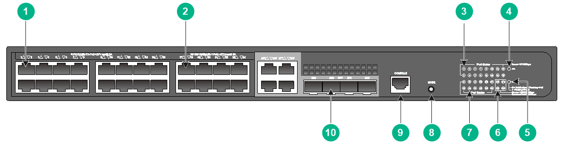
|
(1) 10/100BASE-T autosensing Ethernet port |
(2) 10/100/1000BASE-T autosensing Ethernet port |
|
(3) 10/100BASE-T autosensing Ethernet port LED |
(4) System status LED (SYS) |
|
(5) Mode LED (MODE) |
(6) SFP port LED |
|
(7) 10/100/1000BASE-T autosensing Ethernet port LED |
|
|
(8) Port LED mode switching button |
(9) Console port (CONSOLE) |
|
(10) SFP port |
|
Figure 133 Rear panel (product code LS-3100V3-28TP-PWR-SI)
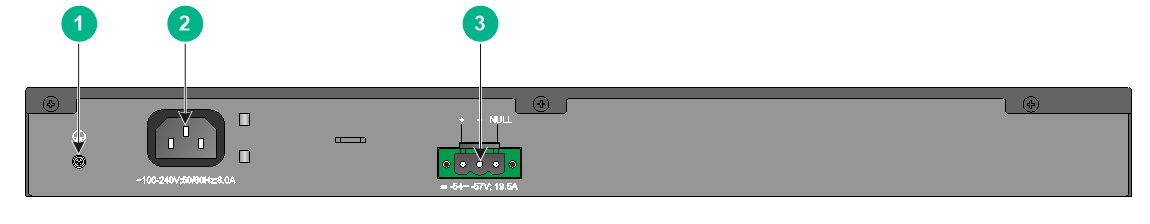
|
(1) Grounding screw |
(2) AC-input power receptacle |
|
(3) DC-input power receptacle |
|
Figure 134 Rear panel (product code LS-3100V3-28TP-PWR-SI-H1)

|
(1) Grounding screw |
(2) AC-input power receptacle |
Removable components
|
|
IMPORTANT: The removable components available for the device might change over time. For the most recent removable components available for the device, see the release notes. |
Power supplies
|
|
CAUTION: · You can replace one power supply for an S5560S-28F-SI, S5560S-28DP-SI, S5500V3-28S-DP-SI, S5500V3-54S-DP-SI, S5500V3-36F-DP-SI, S5500V3-54F-DP-SI, or S5130S-28F-SI switch while the other one is supplying power correctly to the switch. To avoid device damage or body injury, power off the power supply before installing or removing it. · If the S5500V3-54F-DP-SI switch uses the CA-70A12 or PSR75-12A power supplies, you can install a maximum of twelve GE copper transceiver modules (SFP-GE-T or SFP-GE-T-D) on the switch. |
The S5560S-28F-SI, S5560S-28DP-SI, S5500V3-28S-DP-SI, S5500V3-54S-DP-SI, S5500V3-36F-DP-SI, S5500V3-54F-DP-SI, and S5130S-28F-SI switches each provide two power supply slots. One power supply can meet the power requirement of the switch. You can install two power supplies on the switch for redundancy.
Table 20 describes the power supplies available for the S5560S-28F-SI, S5560S-28DP-SI, S5500V3-28S-DP-SI, S5500V3-54S-DP-SI, S5500V3-36F-DP-SI, S5500V3-54F-DP-SI, and S5130S-28F-SI switches. Table 21 describes the power supply specifications
Table 20 Power supplies available for the switches
|
Power supply |
S5560S-28F-SI S5560S-28DP-SI S5130S-28F-SI |
S5500V3-28S-DP-SI S5500V3-54S-DP-SI S5500V3-36F-DP-SI S5500V3-54F-DP-SI |
|
CA-70A12 |
Supported only on the S5130S-28F-SI and S5560S-28F-SI swtiches |
Supported |
|
PSR75-12A |
Supported |
Supported |
|
PSR150-D1 |
N/A |
Supported |
Table 21 Power supply specifications
|
Power supply |
Specifications |
Reference |
|
CA-70A12 |
· Rated input voltage range: 100 VAC to 240 VAC @ 50 Hz or 60 Hz · Max input voltage range: 90 VAC to 290 VAC @ 47 Hz to 63 Hz · Max output power: 70 W |
H3C CA-70A12 Power Supply User Manual |
|
PSR75-12A |
· Rated input voltage range: ¡ AC: 100 VAC to 240 VAC @ 50 Hz or 60 Hz ¡ DC: 240 VDC · Max input voltage range: ¡ AC: 90 VAC to 290 VAC @ 47 Hz to 63 Hz ¡ DC: 180 VDC to 320 VDC · Max output power: 75 W |
H3C PSR75-12A Power supply User Manual |
|
PSR150-D1 |
· Rated input voltage range: –48 VDC to –60 VDC · Max input voltage range: –36 VDC to –72 VDC · Max output power: 150 W |
H3C PSR150-A & PSR150-D Series Power Supplies User Manual |
Ports and LEDs
Ports
Console port
Table 22 Console port specifications
|
Item |
Serial console port |
Micro USB console port |
|
Connector type |
RJ-45 |
Micro USB Type B |
|
Compliant standard |
EIA/TIA-232 |
USB 2.0 |
|
Transmission baud rate |
9600 bps (default) to 115200 bps |
|
|
Services |
· Provides connection to an ASCII terminal. · Provides connection to the serial port of a local PC running terminal emulation program. |
· Provides connection to an ASCII terminal. · Provides connection to the USB port of a local PC running terminal emulation program. |
|
Switch models that provide a console port |
All switch models |
· S5560S-28S-SI, S5560S-52S-SI, S5560S-28F-SI, and S5560S-28DP-SI switches · S5500V3-24P-SI and S5500V3-48P-SI switches · S5130S-SI & S5130S-LI switch series |
|
Restrictions and guidelines |
If you connect both the serial console port and micro USB console port, only the micro USB console port takes effect. |
|
Management Ethernet port
Table 23 Management Ethernet port specifications
|
Item |
Specification |
|
Connector type |
RJ-45 |
|
Port rate and duplex mode |
· 10/100 Mbps, half/full duplex · 1000 Mbps, full duplex (supported only by the SS5500V3-54F-DP-SI switch) |
|
Auto-MDI/MDI-X |
Supported |
|
Transmission medium |
Category-5 and above twisted pair cable |
|
Max transmission distance |
100 m (328.08 ft) |
|
Compliant standard |
IEEE 802.3i, 802.3u, 802.3ab |
|
Functions and services |
Connects to a PC or a remote management station for software and Boot ROM upgrade and network management |
|
Switch models that provide a management Ethernet port |
· S5560S-28F-SI switch · S5560S-28DP-SI switch · S5500V3-54F-DP-SI switch · S5130S-28F-SI switch |
USB port
|
|
IMPORTANT: USB devices from different vendors vary in compatibilities and drivers. H3C does not guarantee correct operation of USB devices from all vendors on the S5560S-28DP-SI switch. If a USB device fails to operate on the switch, replace it with one from another vendor. |
Table 24 USB port specifications
|
Item |
Specification |
|
Port type |
USB2.0 |
|
Compliant standard |
OHC standards |
|
Port rate |
480 Mbps for uploading and downloading |
|
Functions and services |
Exchange files, such as software images and configuration files, with the flash file system on the switch |
|
Switch models that provide a USB port |
S5560S-28DP-SI |
10/100BASE-T autosensing Ethernet port
Table 25 10/100BASE-T autosensing Ethernet port specifications
|
Item |
Specification |
|
Connector type |
RJ-45 |
|
Port rate and duplex mode |
10/100 Mbps, half/full duplex |
|
Auto-MDI/MDI-X |
Supported |
|
Max transmission distance |
100 m (328.08 ft) |
|
Transmission medium |
Category-5 and above twisted pair cable |
|
Compatible standards |
IEEE 802.3i, 802.3u, 802.3ab |
|
Switch models that provide a 10/100BASE-T autosensing Ethernet port |
S3100V3-SI switch series |
10/100/1000BASE-T autosensing Ethernet port
Table 26 10/100/1000BASE-T autosensing Ethernet port specifications
|
Item |
Specification |
|
Connector type |
RJ-45 |
|
Port rate and duplex mode |
· 10/100 Mbps, half/full duplex · 1000 Mbps, full duplex |
|
Auto-MDI/MDI-X |
Supported |
|
Max transmission distance |
100 m (328.08 ft) |
|
Transmission medium |
Category-5 (or above) twisted pair cable |
|
Compatible standards |
IEEE 802.3i, 802.3u, 802.3ab |
|
Switch models that provide a 10/100/1000BASE-T autosensing Ethernet port |
All switch models |
SFP port (LS-5008PV5-EI and LS-5008PV5-EI-HPWR switches)
The SFP ports on the S5008PV5-EI and S5008PV5-EI-HPWR switches support GE SFP transceiver modules described in Table 27 and FE SFP transceiver modules described in Table 28.
Table 27 GE SFP transceiver modules
|
GE SFP transceiver module |
Central wavelength (nm) |
Connector |
Cable specifications |
Modal bandwidth (MHz*km) |
Max transmission distance |
|
Copper SFP transceiver module |
|||||
|
SFP-GE-T |
N/A |
RJ-45 |
Twisted pair cable |
N/A |
100 m (328.09 ft) |
|
Fiber SFP transceiver module |
|||||
|
SFP-GE-SX-MM850-A |
850 |
LC |
50/125 µm, multi-mode optical fiber (MMF) |
500 |
550 m (1804.46 ft) |
|
SFP-GE-LX-SM1310-A |
1310 |
LC |
9/125 µm, single-mode optical fiber (SMF) |
N/A |
10 km (6.21 miles) |
|
SFP-GE-LH40-SM1310 |
1310 |
LC |
9/125 µm, SMF |
N/A |
40 km (24.86 miles) |
|
SFP-GE-LH40-SM1550 |
1550 |
LC |
9/125 µm, SMF |
N/A |
40 km (24.86 miles) |
|
SFP-GE-LH80-SM1550 |
1550 |
LC |
9/125 µm, SMF |
N/A |
80 km (49.71 miles) |
|
SFP-GE-LX-SM1310-BIDI |
TX: 1310 RX: 1490 |
LC |
9/125 µm, SMF |
N/A |
10 km (6.21 miles) |
|
SFP-GE-LX-SM1490-BIDI |
TX: 1490 RX: 1310 |
||||
|
SFP-GE-LH40-SM1310-BIDI |
TX: 1310 RX: 1550 |
LC |
9/125 µm, SMF |
N/A |
40 km (24.86 miles) |
|
SFP-GE-LH40-SM1550-BIDI |
TX: 1550 RX: 1310 |
||||
Table 28 FE SFP transceiver modules
|
Central wavelength (nm) |
Connector |
Cable specifications |
Max transmission distance |
|
|
SFP-FE-SX-MM1310-A |
1310 |
LC |
· 50/125 µm, MMF · 62.5/125 µm, MMF |
2 km (1.24 miles) |
|
SFP-FE-LX-SM1310-A |
1310 |
LC |
9/125 µm, SMF |
15 km (9.32 miles) |
|
SFP-FE-LX-SM1310-BIDI |
TX: 1310 RX: 1550 |
LC |
9/125 µm, SMF |
15 km (9.32 miles) |
|
SFP-FE-LX-SM1550-BIDI |
TX: 1550 RX: 1310 |
|
|
IMPORTANT: The SFP-FE-LX-SM1310-BIDI and SFP-FE-LX-SM1550-BIDI transceiver modules, the SFP-GE-LX-SM1310-BIDI and SFP-GE-LX-SM1490-BIDI transceiver modules, and the SFP-GE-LH40-SM1310-BIDI and SFP-GE-LH40-SM1550-BIDI transceiver modules must be used in pairs. For example, if one end uses an SFP-GE-LX-SM1310-BIDI transceiver module, the other end must use an SFP-GE-LX-SM1490-BIDI transceiver module. |
|
|
NOTE: · As a best practice, use H3C transceiver modules and cables for the switch. · H3C transceiver modules and cables are subject to change over time. For the most up-to-date list of H3C transceiver modules and cables, contact your H3C sales representative or technical support engineer. · For the specifications of H3C transceiver modules and cables, see H3C Transceiver Modules User Guide. |
SFP port (S5500V3-SI switch series)
Only the S5500V3-24P-SI and S5500V3-48P-SI switches do not support the SFP-GE/FE-LX10-SM1310 transceiver module.
Only the S5500V3-24P-SI and S5500V3-48P-SI switches support SFP-GE-SX-MM850-S and SFP-GE-LX-SM1310-S transceiver modules.
If the S5500V3-54F-DP-SI switch uses the CA-70A12 or PSR75-12A power supplies, you can install a maximum of twelve GE copper transceiver modules (SFP-GE-T or SFP-GE-T-D) on the switch.
Table 29 FE SFP transceiver modules available for the SFP ports
|
FE SFP module |
Central wavelength (nm) |
Connector |
Cable specifications |
Max transmission distance |
|
SFP-FE-SX-MM1310-A |
1310 |
LC |
50/125 µm, MMF |
2 km (1.24 miles) |
|
62.5/125 µm, MMF |
||||
|
SFP-GE/FE-LX10-SM1310 |
1310 |
LC |
9/125 µm, SMF |
10 km (6.21 miles) |
|
SFP-FE-LX-SM1310-A |
1310 |
LC |
9/125 µm, SMF |
15 km (9.32 miles) |
|
SFP-FE-LX-SM1310-D |
1310 |
LC |
9/125 µm, SMF |
15 km (9.32 miles) |
|
SFP-FE-LH40-SM1310 |
1310 |
LC |
9/125 µm, SMF |
40 km (24.86 miles) |
|
SFP-FE-LH80-SM1550 |
1550 |
LC |
9/125 µm, SMF |
80 km (49.71 miles) |
|
SFP-FE-LX-SM1310-BIDI |
TX: 1310 RX: 1550 |
LC |
9/125 µm, SMF |
15 km (9.32 miles) |
|
SFP-FE-LX-SM1550-BIDI |
TX: 1550 RX: 1310 |
Table 30 GE SFP transceiver modules and cables available for the SFP ports
|
GE SFP transceiver module and cable |
Central wavelength (nm) |
Connector |
Cable specifications |
Modal bandwidth (MHz × km) |
Max transmission distance |
|
SFP copper transceiver module |
|||||
|
SFP-GE-T |
N/A |
RJ-45 |
Twisted pair cable |
N/A |
100 m (328.08 ft) |
|
SFP-GE-T-D |
N/A |
RJ-45 |
Twisted pair cable |
N/A |
100 m (328.08 ft) |
|
SFP fiber transceiver module |
|||||
|
SFP-GE-SX-MM850-A |
850 |
LC |
50/125 µm, MMF |
500 |
550 m (1804.46 ft) |
|
400 |
500 m (1640.42 ft) |
||||
|
62.5/125 µm, MMF |
200 |
275 m (902.23 ft) |
|||
|
160 |
220 m (721.78 ft) |
||||
|
SFP-GE-SX-MM850-D |
850 |
LC |
50/125 µm, MMF |
500 |
550 m (1804.46 ft) |
|
400 |
500 m (1640.42 ft) |
||||
|
62.5/125 µm, MMF |
200 |
275 m (902.23 ft) |
|||
|
160 |
220 m (721.78 ft) |
||||
|
SFP-GE-SX-MM850-S |
850 |
LC |
50/125 µm, MMF |
500 |
550 m (1804.46 ft) |
|
400 |
500 m (1640.42 ft) |
||||
|
62.5/125 µm, MMF |
200 |
275 m (902.23 ft) |
|||
|
160 |
220 m (721.78 ft) |
||||
|
SFP-GE-LX-SM1310-A |
1310 |
LC |
9/125 µm, SMF |
N/A |
10 km (6.21 miles) |
|
50/125 µm, MMF |
500 or 400 |
550 m (1804.46 ft) |
|||
|
62.5/125 µm, MMF |
500 |
550 m (1804.46 ft) |
|||
|
SFP-GE/FE-LX10-SM1310 |
1310 |
LC |
9/125 µm, SMF |
N/A |
10 km (6.21 miles) |
|
SFP-GE-LX-SM1310-D |
1310 |
LC |
9/125 µm, SMF |
N/A |
10 km (6.21 miles) |
|
SFP-GE-LX-SM1310-S |
1310 |
LC |
9/125 µm, SMF |
N/A |
10 km (6.21 miles) |
|
SFP-GE-LH40-SM1310 |
1310 |
LC |
9/125 µm, SMF |
N/A |
40 km (24.86 miles) |
|
SFP-GE-LH40-SM1310-D |
1310 |
LC |
9/125 µm, SMF |
N/A |
40 km (24.86 miles) |
|
SFP-GE-LH40-SM1550 |
1550 |
LC |
9/125 µm, SMF |
N/A |
40 km (24.86 miles) |
|
SFP-GE-LH80-SM1550 |
1550 |
LC |
9/125 µm, SMF |
N/A |
80 km (49.71 miles) |
|
SFP-GE-LH80-SM1550-D |
1550 |
LC |
9/125 µm, SMF |
N/A |
80 km (49.71 miles) |
|
SFP-GE-LH100-SM1550 |
1550 |
LC |
9/125 µm, SMF |
N/A |
100 km (62.14 miles) |
|
SFP-GE-LX-SM1310-BIDI |
TX: 1310 RX: 1490 |
LC |
9/125 µm, SMF |
N/A |
10 km (6.21 miles) |
|
SFP-GE-LX-SM1490-BIDI |
TX: 1490 RX: 1310 |
LC |
9/125 µm, SMF |
N/A |
10 km (6.21 miles) |
|
SFP-GE-LH40-SM1310-BIDI |
TX: 1310 RX: 1550 |
LC |
9/125 µm, SMF |
N/A |
40 km (24.86 miles) |
|
SFP-GE-LH40-SM1550-BIDI |
TX: 1550 RX: 1310 |
LC |
9/125 µm, SMF |
N/A |
40 km (24.86 miles) |
|
SFP-GE-LH70-SM1490-BIDI |
TX: 1490 RX: 1550 |
LC |
9/125 µm, SMF |
N/A |
70 km (43.49 miles) |
|
SFP-GE-LH70-SM1550-BIDI |
TX: 1550 RX: 1490 |
LC |
9/125 µm, SMF |
N/A |
70 km (43.49 miles) |
|
SFP cable |
|||||
|
SFP-STACK-Kit |
N/A |
1.5 m (4.92 ft) |
|||
|
|
IMPORTANT: The SFP-FE-LX-SM1310-BIDI and SFP-FE-LX-SM1550-BIDI transceiver modules, the SFP-GE-LX-SM1310-BIDI and SFP-GE-LX-SM1490-BIDI transceiver modules, the SFP-GE-LH40-SM1310-BIDI and SFP-GE-LH40-SM1550-BIDI transceiver modules, and the SFP-GE-LH70-SM1490-BIDI and SFP-GE-LH70-SM1550-BIDI transceiver modules must be used in pairs. For example, if one end uses an SFP-GE-LX-SM1310-BIDI transceiver module, the other end must use an SFP-GE-LX-SM1490-BIDI transceiver module. |
|
|
NOTE: · As a best practice, use only H3C SFP transceiver modules and cables for the SFP ports. · The H3C SFP transceiver modules and cables available for the SFP ports are subject to change over time. For the most recent list of SFP transceiver modules and cables available for the SFP port, contact your H3C Support or marketing staff. · For the specifications of H3C SFP transceiver modules and cables, see H3C Transceiver Modules User Guide. |
SFP port (switches other than the S5008PV5-EI and S5008PV5-EI-HPWR)
Table 31 SFP port specifications
|
Switch models |
Supported transceiver models and cables |
Restrictions and guidelines |
|
S5560S-28P-SI S5560S-52P-SI S5560S-28DP-SI |
All the SFP ports support GE SFP transceiver modules and cables in Table 32. The SFP ports 17 to 24 on an S5560S-28DP-SI switch support also the FE SFP transceiver modules in Table 33. |
To use transceiver modules with a maximum transmission distance greater than or equal to 80 km (49.71 miles) on an S5560S-28P-SI switch, make sure the ambient temperature does not exceed 40°C (104°F). |
|
S5560S-28F-SI |
· GE SFP transceiver modules and cables in Table 32. · FE SFP transceiver modules in Table 33. |
To use transceiver modules with a maximum transmission distance greater than or equal to 80 km (49.71 miles), make sure the ambient temperature does not exceed 40°C (104°F). |
|
S5130S-28F-SI S5130S-28S-HPWR-LI |
· GE SFP transceiver modules and cables in Table 32. · FE SFP transceiver modules in Table 33. |
To use transceiver modules with a maximum transmission distance greater than or equal to 80 km (49.71 miles) on an S5130S-28F-SI switch, make sure the ambient temperature does not exceed 40°C (104°F). |
|
S5120V2-SI & S5120V2-LI switch series |
All the SFP ports support GE SFP transceiver modules and cables in Table 32. The SFP ports on an S5120V2-28P-HPWR-LI switch support also FE SFP transceiver modules in Table 33. The SFP ports 9 and 10 on an S5120V2-12TP-HPWR-LI switch support also FE SFP transceiver modules in Table 33. |
To use transceiver modules with a maximum transmission distance greater than or equal to 80 km (49.71 miles) on the following switches, make sure the ambient temperature does not exceed 40°C (104°F). · S5120V2-10P-SI · S5120V2-28P-SI · S5120V2-10P-LI · S5120V2-20P-LI · S5120V2-28P-LI · S5120V2-10P-PWR-LI · S5120V2-12TP-HPWR-LI |
|
S5110V2-SI switch series |
GE SFP transceiver modules and cables in Table 32 |
To use transceiver modules with a maximum transmission distance greater than or equal to 80 km (49.71 miles) on an S5110V2-28P-SI switch, make sure the ambient temperature does not exceed 40°C (104°F). |
|
S5000V3-EI switch series |
All the SFP ports support GE SFP transceiver modules and cables in Table 32. The SFP ports 1 to 26 on an S5024FV3-EI switch support also FE SFP transceiver modules in Table 33. |
To use transceiver modules with a maximum transmission distance greater than or equal to 80 km (49.71 miles) on the S5016PV3-EI and S5024PV3-EI switches, make sure the ambient temperature does not exceed 40°C (104°F). |
|
S5000V5-EI switch series (except for the LS-5008PV5-EI and LS-5008PV5-EI-HPWR switches) |
GE SFP transceiver modules and cables in Table 32 |
To use transceiver modules with a maximum transmission distance greater than or equal to 80 km (49.71 miles) on the S5016PV5-EI, S5016PV5-EI-S, S5024PV5-EI, S5008PV5-EI-S, S5008PV5-EI with product code LS-5008PV5-EI-H1, and S5008PV5-EI-HPWR with product code LS-5008PV5-EI-HPWR-H1 switches, make sure the ambient temperature does not exceed 40°C (104°F). |
|
S3100V3-SI switch series |
All the SFP ports support GE SFP transceiver modules and cables in Table 32. The SFP ports on an S3100V3-28TP-PWR-SI switch support also FE SFP transceiver modules in Table 33. |
To use transceiver modules with a maximum transmission distance greater than or equal to 80 km (49.71 miles) on the following switches, make sure the ambient temperature does not exceed 40°C (104°F). · S3100V3-10TP-SI · S3100V3-18TP-SI · S3100V3-28TP-SI · S3100V3-10TP-PWR-SI |
Table 32 GE SFP transceiver modules and cables
|
GE SFP transceiver module/cable |
Central wavelength (nm) |
Connector |
Cable specifications |
Modal bandwidth (MHz*km) |
Max transmission distance |
|
Copper SFP transceiver module |
|||||
|
SFP-GE-T |
N/A |
RJ-45 |
Twisted pair cable |
N/A |
100 m (328.09 ft) |
|
SFP-GE-T-D |
N/A |
RJ-45 |
Twisted pair cable |
N/A |
100 m (328.09 ft) |
|
Fiber SFP transceiver module |
|||||
|
SFP-GE-SX-MM850-A |
850 |
LC |
50/125 µm, MMF |
500 |
550 m (1804.46 ft) |
|
400 |
500 m (1640.42 ft) |
||||
|
62.5/125 µm, MMF |
200 |
275 m (902.23 ft) |
|||
|
160 |
220 m (721.78 ft) |
||||
|
SFP-GE-SX-MM850-D |
850 |
LC |
50/125 µm, MMF |
500 |
550 m (1804.46 ft) |
|
400 |
500 m (1640.42 ft) |
||||
|
62.5/125 µm, MMF |
200 |
275 m (902.23 ft) |
|||
|
160 |
220 m (721.78 ft) |
||||
|
SFP-GE-SX-MM850-S |
850 |
LC |
50/125 µm, MMF |
500 |
550 m (1804.46 ft) |
|
400 |
500 m (1640.42 ft) |
||||
|
62.5/125 µm, MMF |
200 |
275 m (902.23 ft) |
|||
|
160 |
220 m (721.78 ft) |
||||
|
SFP-GE-LX-SM1310-A |
1310 |
LC |
9/125 µm, SMF |
N/A |
10 km (6.21 miles) |
|
50/125 µm, MMF |
500/400 |
550 m (1804.46 ft) |
|||
|
62.5/125 µm, MMF |
500 |
550 m (1804.46 ft) |
|||
|
SFP-GE-LX-SM1310-D |
1310 |
LC |
9/125 µm, SMF |
N/A |
10 km (6.21 miles) |
|
SFP-GE-LX-SM1310-S |
1310 |
LC |
9/125 µm, SMF |
N/A |
10 km (6.21 miles) |
|
SFP-GE-LH40-SM1310 |
1310 |
LC |
9/125 µm, SMF |
N/A |
40 km (24.86 miles) |
|
SFP-GE-LH40-SM1310-D |
1310 |
LC |
9/125 µm, SMF |
N/A |
40 km (24.86 miles) |
|
SFP-GE-LH40-SM1550 |
1550 |
LC |
9/125 µm, SMF |
N/A |
40 km (24.86 miles) |
|
SFP-GE-LH80-SM1550 |
1550 |
LC |
9/125 µm, SMF |
N/A |
80 km (49.71 miles) |
|
SFP-GE-LH80-SM1550-D |
1550 |
LC |
9/125 µm, SMF |
N/A |
80 km (49.71 miles) |
|
SFP-GE-LH100-SM1550 |
1550 |
LC |
9/125 µm, SMF |
N/A |
100 km (62.14 miles) |
|
SFP-GE-LX-SM1310-BIDI |
TX: 1310 RX: 1490 |
LC |
9/125 µm, SMF |
N/A |
10 km (6.21 miles) |
|
SFP-GE-LX-SM1490-BIDI |
TX: 1490 RX: 1310 |
||||
|
SFP-GE-LH40-SM1310-BIDI |
TX: 1310 RX: 1550 |
LC |
9/125 µm, SMF |
N/A |
40 km (24.86 miles) |
|
SFP-GE-LH40-SM1550-BIDI |
TX: 1550 RX: 1310 |
||||
|
SFP-GE-LH70-SM1490-BIDI |
TX: 1490 RX: 1550 |
LC |
9/125 µm, SMF |
N/A |
70 km (43.49 miles) |
|
SFP-GE-LH70-SM1550-BIDI |
TX: 1550 RX: 1490 |
||||
|
SFP cable |
|||||
|
SFP-STACK-Kit |
N/A |
N/A |
SFP cable |
N/A |
1.5 m (4.92 ft) |
Table 33 FE SFP transceiver modules
|
FE SFP transceiver module |
Central wavelength (nm) |
Connector |
Cable specifications |
Max transmission distance |
|
SFP-FE-SX-MM1310-A |
1310 |
LC |
· 50/125 µm, MMF · 62.5/125 µm, MMF |
2 km (1.24 miles) |
|
SFP-FE-LX-SM1310-A |
1310 |
LC |
9/125 µm, SMF |
15 km (9.32 miles) |
|
SFP-FE-LX-SM1310-D |
1310 |
LC |
9/125 µm, SMF |
15 km (9.32 miles) |
|
SFP-FE-LH40-SM1310 |
1310 |
LC |
9/125 µm, SMF |
40 km (24.86 miles) |
|
SFP-FE-LH80-SM1550 |
1550 |
LC |
9/125 µm, SMF |
80 km (49.71 miles) |
|
SFP-FE-LX-SM1310-BIDI |
TX: 1310 RX: 1550 |
LC |
9/125 µm, SMF |
15 km (9.32 miles) |
|
SFP-FE-LX-SM1550-BIDI |
TX: 1550 RX: 1310 |
|
|
IMPORTANT: The SFP-FE-LX-SM1310-BIDI and SFP-FE-LX-SM1550-BIDI transceiver modules, the SFP-GE-LX-SM1310-BIDI and SFP-GE-LX-SM1490-BIDI transceiver modules, the SFP-GE-LH40-SM1310-BIDI and SFP-GE-LH40-SM1550-BIDI transceiver modules, and the SFP-GE-LH70-SM1490-BIDI and SFP-GE-LH70-SM1550-BIDI transceiver modules must be used in pairs. For example, if one end uses an SFP-GE-LX-SM1310-BIDI transceiver module, the other end must use an SFP-GE-LX-SM1490-BIDI transceiver module. |
|
|
NOTE: · As a best practice, use H3C transceiver modules and cables for the switch. · H3C transceiver modules and cables are subject to change over time. For the most up-to-date list of H3C transceiver modules and cables, contact your H3C sales representative or technical support engineer. · For the specifications of H3C transceiver modules and cables, see H3C Transceiver Modules User Guide. |
SFP+ port
Table 34 SFP+ port specifications
|
Item |
Specifications |
|
Port type |
SFP+ port |
|
Supported transceiver modules and cables |
· GE SFP transceiver modules and cables in Table 32 · 10-GE SFP+ transceiver modules and cables in Table 35 |
|
Switch models that provide SFP+ ports |
· S5560S-28S-SI, S5560S-52S-SI, and S5560S-28F-SI switches · S5500V3-SI switch series · S5130S-SI & S5130S-LI switch series |
|
Restrictions and guidelines |
· A 10-GE SFP+ transceiver module is built into each 10GBASE-SX-FD-MM-SR port on the S5130S-28S-SI-MM and S5130S-28S-LI-MM switches and each 10GBASE-LX-FD-SM-IR port on the S5130S-28S-SI-SM and S5130S-28S-LI-SM switches. Select optical fibers for these ports based on the port type and transmission distance. · All S5500V3-SI switches except for the S5500V3-24P-S and S5500V3-48P-SI support a maximum of two 10-GE transceiver modules with a maximum transmission distance of 80 km (49.71 miles). · All S5500V3-SI switches except for the 5500V3-24P-SI and S5500V3-48P-SI do not support the SFP-XG-SX-MM850-S, SFP-XG-SX-MM850-E, SFP-XG-LX-SM1310-S, or SFP-XG-LX-SM1310-E transceiver module, or the LSTM1STK cable. · Only S5500V3-SI switches (except for the S5500V3-24P-SI and S5500V3-48P-SI) support SFP-GE/FE-LX10-SM1310, SFP-XG-SX-MM850-A, SFP-XG-LX-SM1310, SFP-XG-LH80-SM1490-BIDI, and SFP-XG-LH80-SM1550-BIDI transceiver modules. |
Table 35 10-GE SFP+ transceiver modules and cables available for the SFP+ ports
|
10-GE SFP+ transceiver module/cable |
Central wavelength (nm) |
Connector |
Cable specifications |
Modal bandwidth (MHz*km) |
Max transmission distance |
|
10-GE SFP+ transceiver module |
|||||
|
SFP-XG-SX-MM850-A |
850 |
LC |
50/125 µm, MMF |
2000 |
300 m (984.3 ft) |
|
500 |
82 m (269.03 ft) |
||||
|
400 |
66 m (216.54 ft) |
||||
|
62.5/125 µm, MMF |
200 |
33 m (108.27 ft) |
|||
|
160 |
26 m (85.30 ft) |
||||
|
SFP-XG-SX-MM850-D |
850 |
LC |
50/125 µm, MMF |
2000 |
300 m (984.3 ft) |
|
500 |
82 m (269.03 ft) |
||||
|
400 |
66 m (216.54 ft) |
||||
|
62.5/125 µm, MMF |
200 |
33 m (108.27 ft) |
|||
|
160 |
26 m (85.30 ft) |
||||
|
SFP-XG-SX-MM850-S |
850 |
LC |
50/125 µm, MMF |
2000 |
300 m (984.3 ft) |
|
500 |
82 m (269.03 ft) |
||||
|
400 |
66 m (216.54 ft) |
||||
|
62.5/125 µm, MMF |
200 |
33 m (108.27 ft) |
|||
|
160 |
26 m (85.30 ft) |
||||
|
SFP-XG-SX-MM850-E |
850 |
LC |
50/125 µm, MMF |
2000 |
300 m (984.3 ft) |
|
500 |
82 m (269.03 ft) |
||||
|
400 |
66 m (216.54 ft) |
||||
|
62.5/125 µm, MMF |
200 |
33 m (108.27 ft) |
|||
|
160 |
26 m (85.30 ft) |
||||
|
SFP-XG-LX-SM1310 |
1310 |
LC |
9/125 µm, SMF |
N/A |
10 km (6.21 miles) |
|
SFP-XG-LX-SM1310-D |
1310 |
LC |
9/125 µm, SMF |
N/A |
10 km (6.21 miles) |
|
SFP-XG-LX-SM1310-E |
1310 |
LC |
9/125 µm, SMF |
N/A |
10 km (6.21 miles) |
|
SFP-XG-LX-SM1310-S |
1310 |
LC |
9/125 µm, SMF |
N/A |
10 km (6.21 miles) |
|
SFP-XG-LH40-SM1550 |
1550 |
LC |
9/125 µm, SMF |
N/A |
40 km (24.86 miles) |
|
SFP-XG-LH40-SM1550-D |
1550 |
LC |
9/125 µm, SMF |
N/A |
40 km (24.86 miles) |
|
SFP-XG-LH80-SM1550 |
1550 |
LC |
9/125 µm, SMF |
N/A |
80 km (49.71 miles) |
|
SFP-XG-LH80-SM1550-D |
1550 |
LC |
9/125 µm, SMF |
N/A |
80 km (49.71 miles) |
|
SFP-XG-LX-SM1270-BIDI |
TX: 1270 RX: 1330 |
LC |
9/125 µm, SMF |
N/A |
10 km (6.21 miles) |
|
SFP-XG-LX-SM1330-BIDI |
TX: 1330 RX: 1270 |
||||
|
SFP-XG-LH40-SM1270-BIDI
|
TX: 1270 RX: 1330 |
LC |
9/125 µm, SMF |
N/A |
40 km (24.86 miles) |
|
SFP-XG-LH40-SM1330-BIDI |
TX: 1330 RX: 1270 |
||||
|
SFP-XG-LH80-SM1490-BIDI |
TX: 1490 RX: 1550 |
LC |
9/125 µm, SMF |
N/A |
80 km (49.71 miles) |
|
SFP-XG-LH80-SM1550-BIDI |
TX: 1550 RX: 1490 |
LC |
9/125 µm, SMF |
N/A |
80 km (49.71 miles) |
|
SFP+ copper cable |
|||||
|
LSWM1STK |
N/A |
0.65 m (2.13 ft) |
|||
|
LSWM2STK |
N/A |
1.2 m (3.94 ft) |
|||
|
LSWM3STK |
N/A |
3 m (9.84 ft) |
|||
|
LSTM1STK |
N/A |
5 m (16.40 ft) |
|||
|
SFP+ optical cable |
|||||
|
SFP-XG-D-AOC-7M |
N/A |
7 m (22.97 ft) |
|||
|
SFP-XG-D-AOC-10M |
N/A |
10 m (32.81 ft) |
|||
|
SFP-XG-D-AOC-20M |
N/A |
20 m (65.62 ft) |
|||
|
|
IMPORTANT: The SFP-XG-LX-SM1270-BIDI and SFP-XG-LX-SM1330-BIDI transceiver modules, the SFP-XG-LH40-SM1270-BIDI and SFP-XG-LH40-SM1330-BIDI transceiver modules, and the SFP-XG-LH80-SM1490-BIDI and SFP-XG-LH80-SM1550-BIDI transceiver modules must be used in pairs. For example, if one end uses an SFP-XG-LX-SM1270-BIDI transceiver module, the other end must use an SFP-XG-LX-SM1330-BIDI transceiver module. |
Table 36 Built-in SFP+ transceiver module specifications
|
Built-in SFP+ transceiver module |
Central wavelength (nm) |
Connector |
Cable specifications |
Modal bandwidth (MHz*km) |
Max transmission distance |
|
10GBASE-SX-FD-MM-SR |
850 nm |
LC |
50/125 µm, MMF |
2000 |
300 m (984.25 ft) |
|
10GBASE-LX-FD-SM-IR |
1310 nm |
LC |
9/125µm, SMF |
N/A |
10 km (6.21 miles) |
H3C provides SFP+ cables of multiple lengths. For the available SFP+ cables, see Table 35.
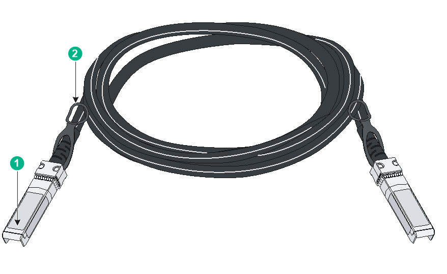
|
(1) Connector |
(2) Pull latch |
|
|
NOTE: · As a best practice, use H3C transceiver modules and cables for the switch. · H3C transceiver modules and cables are subject to change over time. For the most up-to-date list of H3C transceiver modules and cables, contact your H3C sales representative or technical support engineer. · For the specifications of H3C transceiver modules and cables, see H3C Transceiver Modules User Guide. |
Combo interface
Table 37 Combo interface specifications
|
Item |
Specifications |
|
Interface type |
Combo interface. |
|
Interface attributes |
Each combo interface contains an SFP port and a 10/100/1000BASE-T autosensing Ethernet port. Only one of the two ports is active at a time. |
|
Switch models that provide combo interfaces |
· S5560S-28F-SI, S5560S-28DP-SI, and S5130S-28F-SI switches—Eight combo interfaces on the front panel. · S5130S-28S-HPWR-LI, S5120V2-28P-HPWR-LI, and S3100V3-28TP-PWR-SI switches—Four combo interfaces on the front panel. · S5120V2-12TP-HPWR-LI and S5024FV3-EI switches—Two combo interfaces on the front panel. |
LEDs
System status LED
The system status LED shows the operating status of the switch.
Table 38 System status LED description
|
LED mark |
Status |
Description |
|
SYS |
Steady yellow |
Boot ROM booting stage. |
|
Steady green |
Linux kernel booting stage, or the switch has started up correctly. |
|
|
Flashing green (1 Hz) |
Software image loading and decompressing stage, or software booting stage. |
|
|
Steady red |
The switch has failed POST or the switch is faulty. |
|
|
Off |
The switch is powered off or has not started up correctly. |
Management Ethernet port LED
The device provides a LED for each management Ethernet port to indicate its operating status.
Table 39 Management Ethernet port LED description
|
Management Ethernet port LED (ACT/LINK) status |
Description |
|
Steady green |
A link is present on the port. |
|
Flashing yellow |
The port is sending or receiving data. |
|
Off |
No link is present on the port. |
Power supply status LED
Each removable power supply provides a status LED on the front panel to indicate its operating status.
Table 40 Power supply status LED description
|
LED mark |
Status |
Description |
|
PWR1/PWR1 |
Steady green |
A power supply is installed in the power supply slot, and the power supply is outputting power correctly. |
|
Steady yellow |
A power supply is installed in the power supply slot, but the power supply is faulty or no power is being supplied to the power supply. |
|
|
Off |
No power supply is installed in the power supply slot. |
RPS status LED
All switches that use fixed power supplies and support RPS DC power input (except for the S5024PV3-EI-HPWR) have an RPS status LED to indicate the power input status.
Table 41 RPS status LED description
|
LED mark |
Status |
Description |
|
RPS |
Steady green |
Both the RPS input and the AC input are normal. |
|
Steady yellow |
Normal RPS input, no or abnormal AC input. |
|
|
Off |
No or abnormal DC input. |
Mode LED (MODE)
In addition to port status LEDs, some switches provide a mode button and mode LED. You can use the mode button to change the indication of the mode LED. The mode LED and port status LED work in combination to indicate the port status from different aspects.
Table 42 Description for the mode LED
|
LED mark |
Status |
Description |
|
Mode LED (MODE) |
Steady green |
The port LEDs are showing link state of the ports. |
|
Flashing green (Available only for PoE switch models) |
The port LEDs are showing the PoE status of the ports. |
|
|
Flashing yellow |
The port LEDs work in conjunction to indicate the IRF member ID of the switch. For example, if the LED for port 5 is steady green, the IRF member ID of the switch is 5. |
SFP port LED (S5500V3-36F-DP-SI switch)
Table 43 SFP port LED description
|
Mode LED status |
SFP port LED status |
Description |
|
Steady green (Link/Active mode) |
Steady green |
A link is present on the port. |
|
Flashing green |
The port is sending or receiving data. |
|
|
Off |
No link is present on the port. |
|
|
Flashing yellow (IRF mode) |
Steady green |
The SFP port LEDs on the switch work in conjunction to indicate the IRF member ID of the switch. For example, if the LED for port 5 is steady green and the other port LEDs are off, the IRF member ID of the switch is 5. |
SFP/SFP+ port LED
Table 44 SFP/SFP+ port LED description
|
Status |
Description |
|
Steady green |
A link is present on the port. |
|
Flashing green |
The port is sending or receiving data. |
|
Off |
· No link is present on the port. · The mode LED is operating in IRF mode (available only for switch models with a mode button) · The mode LED is operating in PoE mode (available only for PoE switch models) |
10/100BASE-T autosensing Ethernet port LED and 10/100/1000BASE-T autosensing Ethernet port LED
For switch models that supports port LED mode switching, see Table 45 for the 10/100BASE-T autosensing Ethernet port and 10/100/1000BASE-T autosensing Ethernet port LED description.
For switch models that do not support port LED mode switching, see Table 46 for the 10/100BASE-T autosensing Ethernet port and 10/100/1000BASE-T autosensing Ethernet port LED description.
|
Mode LED status |
10/100BASE-T autosensing Ethernet port or 10/100/1000BASE-T autosensing Ethernet port LED status |
Description |
|
Steady green (Link/Active mode) |
Steady green |
A link is present on the port. |
|
Flashing green |
The port is sending or receiving data. |
|
|
Off |
No link is present on the port. |
|
|
Flashing green (PoE mode) (available only for PoE switch models) |
Steady green |
PoE power supply is normal. |
|
Flashing green (1 Hz) |
· The maximum PoE power provided by the port fails to meet the power requirement of the PD. · PoE power supply overcurrent, overvoltage, or short-circuit occurs. · The remaining power of the switch fails to meet the power supply requirement of the port. |
|
|
Off |
The port is not connected to a PD or PoE is not enabled on the port. |
|
|
Flashing yellow (IRF mode) |
Steady green |
The 10/100/1000BASE-T autosensing Ethernet port LEDs on the switch work in conjunction to indicate the IRF member ID of the switch. For example, if the LED for port 5 is steady green and the other port LEDs are off, the IRF member ID of the switch is 5. |
Table 46 10/100BASE-T autosensing Ethernet port LED and 10/100/1000BASE-T autosensing Ethernet port LED description
|
LED status |
Description |
|
Steady green |
A link is present on the port. |
|
Flashing green |
The port is sending or receiving data. |
|
Off |
No link is present on the port. |
