- Table of Contents
- Related Documents
-
| Title | Size | Download |
|---|---|---|
| 01-Text | 847.74 KB |
Opening or closing the LCD screen
Viewing real-time monitoring information
Restoring the default administrator account
Safety information
To avoid bodily injury or damage to the LCD module, read the following information carefully before you operate the module.
General operating safety
To avoid bodily injury or damage to the module, follow these guidelines when you operate the module:
· Only H3C authorized or professional engineers are allowed to operate the module.
· Keep the LCD module clean and dust-free. Do not place the module in a moist place and prevent liquid from flowing into the module.
Electrical safety
To avoid bodily injury or damage to the module, follow these guidelines:
· Examine the work area for potential risks. For example, the server is not correctly grounded or the floor is wet.
· As a best practice, do not operate the module alone when the module is powered on.
ESD prevention
Preventing electrostatic discharge
To prevent electrostatic damage, follow these guidelines:
· Transport or store the server with the components in antistatic bags.
· Keep the electrostatic-sensitive components in separate antistatic bags until they arrive at an ESD-protected area.
· Place the components on a grounded surface before removing them from their antistatic bags.
· Avoid touching pins, leads, or circuitry.
· Take ESD prevention measures before touching any electrostatic-sensitive component.
Grounding methods to prevent electrostatic discharge
The following are grounding methods that you can use to prevent electrostatic discharge:
· Wear an ESD wrist strap and make sure it makes good skin contact and is reliably grounded.
· Take adequate personal grounding measures, including wearing antistatic clothing and static dissipative shoes.
· Use conductive field service tools.
· Use a portable field service kit with a folding static-dissipating work mat.
Identifying the LCD module
|
|
NOTE: · The LCD touchable intelligent management module is also referred to as the LCD module in this document. · Figures in this document are for illustration only. · Software screenshots in this document are for illustration only and might change without notice. |
About the LCD module
A Liquid Crystal Display (LCD) module installed on a server allows users to view basic server information and real-time monitoring and fault information, configure the HDM network and administrator account, and restart the LCD screen. It helps users fast locate the faulty components and maintain the correct operation of each component and the server system.
The document is applicable to the following servers:
· H3C UniServer R6700 G3
· H3C UniServer R6900 G3
· H3C UniServer R8900 G3
· H3C UniServer R4700 G5
· H3C UniServer R4900 G5
· H3C UniServer R4950 G5
· H3C UniServer R6900 G5
LCD module components
Figure 1 LCD module components
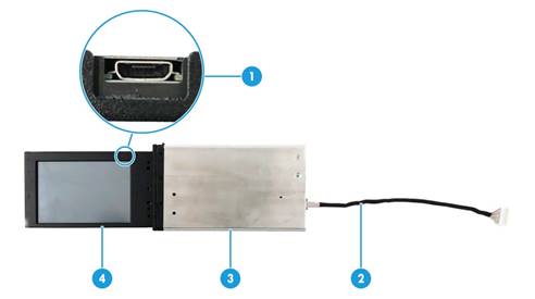
Table 1 LCD module components
|
No. |
Name |
Description |
|
1 |
Mini-USB connector |
Used for LCD firmware update. |
|
2 |
LCD module cable |
Used to connect to the LCD module connector in the server through the extension cable. For more information about the connector location in the system, see the user guide for the server. |
|
3 |
LCD module casing |
Used to protect and secure the LCD screen. |
|
4 |
LCD screen |
Used to display basic server information, real-time monitoring information, and fault information. |
Installation location
The installation location of the LCD module varies by server model. For more information, see the user guide for the server.
Installing the LCD module
The installation method of the LCD module varies by server model. For more information, see the user guide for the server.
Updating the LCD firmware
For more information, see H3C Servers Firmware Update Guide.
Opening or closing the LCD screen
1. Press the LCD screen gently. The LCD screen will pop up automatically.
2. Hold the LCD screen and slowly pull it out of the slot until it stops.
3. If the LCD module is installed vertically, rotate the screen 90 degree toward the server left.
4. If the LCD module is installed horizontally, rotate the LCD 90 degree downwards, and then rotate the screen against the server panel 90 degree clockwise.
To close the LCD screen:
1. Follow the screen opening steps in reverse, and rotate the LCD screen until it can fit into the slot.
2. Slightly press the LCD screen into the slot until you cannot push it further.
Using the LCD module
|
|
NOTE: · The LCD screen can display a maximum of 32 characters. If the display is incomplete, access the HDM Web interface to view the complete information. · This chapter is applicable only to LCD_FW_1.04.01_EN and later versions. |
General buttons
Table 2 lists buttons that might appear on the LCD screen.
Table 2 General buttons
|
Button |
Description |
|
Return to the upper-layer page. |
|
|
|
Jump to the next page. |
|
|
Confirm the operation or configuration change. |
|
|
Enter the settings page. |
Viewing common information
Procedure
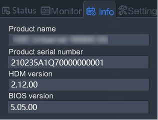
Open the LCD module. You can view the product name, product serial number, HDM version, and the BIOS version.
Figure 2 Viewing common information
Parameters
· Product name: Name of the server.
· Product serial number: Serial number of the server.
· HDM version: Version of HDM used by the server.
· BIOS version: Version of the BIOS used by the server.
Viewing alarm information
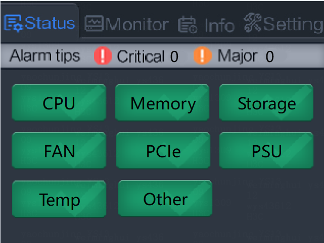
Perform this task to view alarm information and the health status of subsystems, including CPUs, memory, storage, fans, PCIe modules, power supplies, temperature, and others.
To view alarm information:
1. Click the Status tab and view alarm information and the health status of subsystems. The status of a subsystem is indicated by the icon color. For more information about alarm icons and subsystem icons, see Table 3 and Table 4, respectively.
Figure 3 Viewing alarm information
|
Icon |
Description |
|
|
A severe alarm is present. The system operation might be affected and service interruption might occur. |
|
|
A critical alarm is present. The server might be powered off and the system operation might be terminated. Immediate action is required. |
|
Icon color |
Description |
|
|
The subsystem is operating correctly. |
|
|
A severe error has occurred in the subsystem and the component performance has obviously degraded. |
|
|
A critical error has occurred in the subsystem and the server might be powered off automatically to prevent component damage. |
2. If a subsystem has health issues, access the HDM Web interface to view the alarm details. For more information, see the HDM user guide.
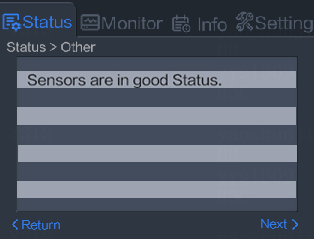
¡ For storage, PCIe modules, temperature, and others, the screen displays only components with health issues.
Figure 4 Storage summary
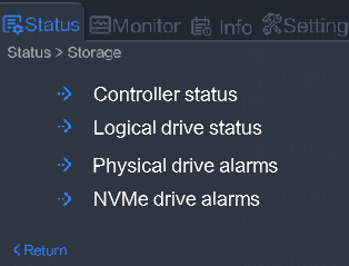
Figure 5 Storage details

Figure 6 PCIe module status
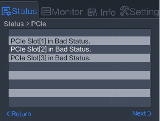
Figure 7 Temperature status
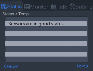
Figure 8 Other status (all components are healthy)
¡ For the other subsystems, the screen displays all components. The status of a component is indicated by the icon color. For more information, see Table 5.
Figure 9 CPU status
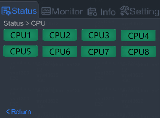
Figure 10 Fan status
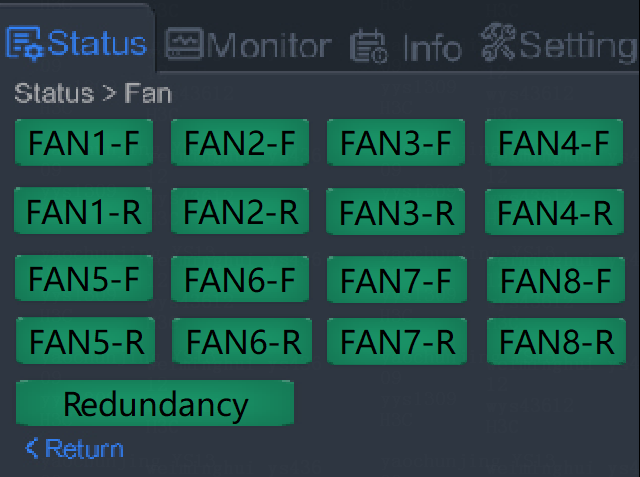
Figure 11 Power supply status
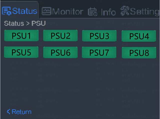
Figure 12 Memory status
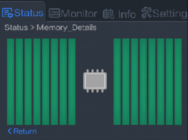
Table 5 Subsystem component icons
|
Icon |
Description |
|
|
The subsystem component is operating correctly. |
|
|
A minor error is present on the subsystem component and the component performance has slightly degraded. |
|
|
A major error is present on the subsystem component and the component performance has obviously degraded. |
|
|
A critical error is present on the subsystem component and the server might be powered off automatically to prevent component damage. |
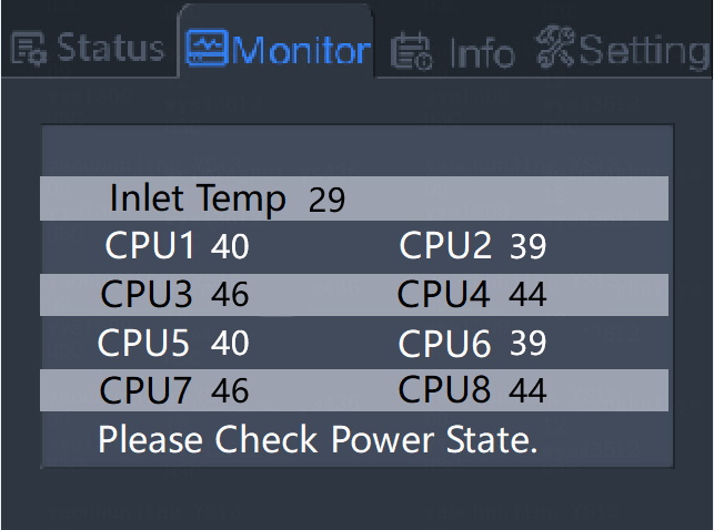
Viewing real-time monitoring information
Perform this task to view the CPU temperature and the air inlet temperature.
Restrictions and guidelines
If a subsystem component is absent or unavailable, the temperature value is displayed N/A for the component.
If the server is powered off, the temperature value is displayed as N/A for all the components.
Procedure
Click the Monitor tab.
Figure 13 Viewing real-time monitoring information
Parameters
Inlet Temp: Air inlet temperature.
Configuring the LCD module
Perform this task to configure the HDM management interface, such as the IPv4 address, subnet mask, and default gateway.
· If the HDM network port is in normal mode, you can change the network settings for the HDM dedicated network port.
· If the HDM network port is in bonding or active/standby mode, you cannot change the network settings for the HDM management interface in use.
Restrictions and guidelines
This operation causes HDM to restart.
Procedure
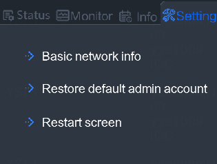
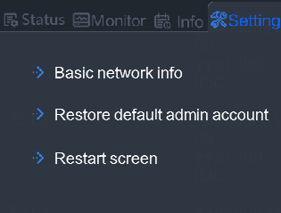
1. Click the Setting tab.
Figure 14 Setting tab
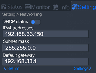
2. View network basics.
Figure 15 Viewing network basics
3. Click Settings at the bottom right corner.
Figure 16 Access the settings page
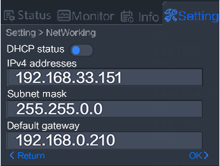
4. Specify the method for the HDM management interface to obtain network settings.
¡ If you enable DHCP, the interface automatically obtains an IPv4 address, subnet mask, and the default gateway.
¡ If you disable DHCP, you must specify an IPv4 address, the subnet mask, and the default gateway manually.
5. Click OK to save the configuration.
Restoring the default administrator account
The default administrator account is named admin and uses password Password@_.
Restrictions and guidelines
Restoring the default administrator account deletes the user-defined account named admin. After the restoration, you cannot use the user-defined account named admin to access HDM.
Procedure
1. Click the Setting tab.
Figure 17 Setting tab

2. Click Restore default admin account.
Figure 18 Restoring the default admin account
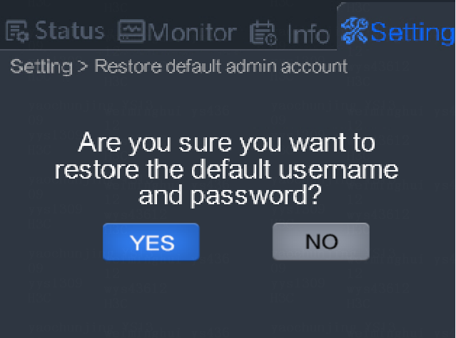
3. Click Yes to confirm the operation or click No to cancel the operation.
Restarting the LCD screen
Perform this task to restart the LCD screen if the screen display is faulty.
To restart the LCD screen:
1. Click the Setting tab.
Figure 19 Setting tab
2. Click Restart screen.
