- Table of Contents
- Related Documents
-
| Title | Size | Download |
|---|---|---|
| 03-LEDs | 694.64 KB |
Environment management module LEDs
Active/standby status LEDs for environment management modules
ETH management port status LEDs
Port status LEDs on interface modules
Fabric module status LED on a fabric module
Fabric module status LEDs on a fan tray
3 LEDs
The device components provide various LEDs to indicate the component operating status.
Table 3-1 LEDs at a glance
|
LEDs |
|
MPU LEDs
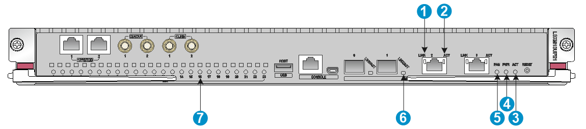
The following figure uses the LSXM1SUPER1 MPU for illustration.
Figure 3-1 LSXM1SUPER1 MPU LEDs
|
(1) 10/100/1000BASE-T management Ethernet port LED (LINK) |
|
|
(2) 10/100/1000BASE-T management Ethernet port LED (ACT) |
|
|
(3) MPU active/standby status LED (ACT) |
(4) Power module status LED (PWR) |
|
(5) Fan tray status LED (FAN) |
(6) SFP management Ethernet port LED (LINK/ACT) |
|
(7) Module status LED (SLOT) |
|
Management Ethernet port LEDs
10/100/1000BASE-T management Ethernet port LEDs
Each 10/100/1000BASE-T management Ethernet port has a pair of LEDs (LINK and ACT) or a single LED to indicate its operating status.
For the description of the pair of LEDs, see Table 3-2.
Table 3-2 Description for the pair of LEDs for a 10/100/1000BASE-T management Ethernet port
|
LINK |
ACT |
Description |
|
Off |
Off |
No link is present. |
|
Steady green |
Off |
A 1000 Mbps link is present. |
|
Steady orange |
Off |
A 10/100 Mbps link is present. |
|
Steady green |
Flashing yellow |
The port is receiving or sending data at 1000 Mbps. |
|
Steady orange |
Flashing yellow |
The port is receiving or sending data at 10/100 Mbps. |
SFP management Ethernet port LED
Each SFP management Ethernet port has a LED to indicate its operating status.
Table 3-3 SFP management Ethernet port LED description
|
Status |
Description |
|
Flashing |
The port is sending or receiving data. |
|
On |
A link is present on the port. |
|
Off |
No link is present on the port. |
Fan tray status LEDs
An MPU provides one fan tray status LED to indicate the status of the fan trays. For the description of the LED, see Table 3-4.
Table 3-4 Fan tray status LED description for MPUs
|
Status |
Description |
|
Steady green |
All fan trays are operating correctly. |
|
Steady red |
A fan tray problem is present or no fan tray is in position. |
|
Off |
The device is not powered on. |
Power module status LEDs
An MPU provides one power module status LED to indicate the status of the power modules. For the description of the LED, see Table 3-5.
Table 3-5 Power module status LED description for MPUs
|
Status |
Description |
|
Steady green |
All power modules are operating correctly. |
|
Steady red |
A minimum of one power module is faulty. |
|
Off |
The device is not powered on. |
Module status LEDs
An MPU provides one status LED for each module. For the description of the LED, see Table 3-6.
|
|
NOTE: The MPU and service module slot numbers are marked on the ejector lever pillow blocks at the left and right sides of the slots. The fabric module slot number is marked above the slot. |
Table 3-6 Module status LED description
|
ALM |
Description |
|
Flashing green (once every two seconds) |
The module is operating correctly. |
|
Flashing green (four times per second) |
The module is loading software. If the LED keeps flashing green four times per second, the software versions of the device and the module do not match. |
|
Steady green |
The module is starting up. |
|
Steady red |
A warning or error alarm was triggered or the module is faulty. |
|
Flashing red (once every four seconds) |
The temperature of the module is higher than the warning threshold or lower than the low-temperature threshold. |
|
Off |
The module is not in position or the module is faulty. |
MPU active/standby status LED
An MPU has one LED to indicate the active or standby status of the MPU.
Table 3-7 MPU active/standby LED description
|
LED status |
Description |
|
On |
The MPU is active. |
|
Off |
· The MPU is in standby status. · The MPU is faulty. Examine the module LED for an MPU problem. |
Environment management module LEDs
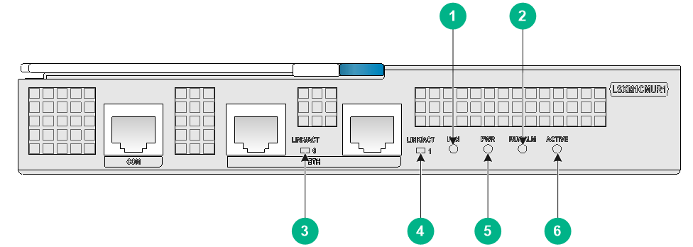
The following figure uses the LSXM1CMUR1 environment management module for illustration.
Figure 3-2 LSXM1CMUR1 environment management module LEDs
|
(1) Fan tray status LED (FAN) |
(2) Operating status LED (RUN/ALM) |
|
|
(3) ETH management port status LED (LINK/ACT0) |
(4) ETH management port status LED (LINK/ACT1) |
|
|
(5) Power module status LED (PWR) |
(6) Active/standby status LED for the environment management module (ACTIVE) |
|
Fan tray status LEDs
An environment management module provides one fan tray status LED to indicate the status of the fan trays. For the description of the LED, see Table 3-8.
Table 3-8 Fan tray status LED description for environment management modules
|
Status |
Description |
|
Steady green |
All fan trays are operating correctly. |
|
Steady red |
A fan tray issue is present or no fan tray is in position. |
|
Off |
The device is not powered on. |
Power module status LEDs
An environment management module provides one power module status LED to indicate the status of the power modules. For the description of the LED, see Table 3-9.
Table 3-9 Power module status LED description for environment management modules
|
Status |
Description |
|
Steady green |
All power modules are operating correctly. |
|
Steady red |
A minimum of one power module is faulty. |
|
Off |
The device is not powered on. |
The power module status LED for the environment management module is steady green only when all power modules are operating correctly. Once a power module is faulty, the power module status LED becomes steady red.
Operating status LEDs
An environment management module provides one operating status LED to indicate the operating status of the environment management module. For the description of the LED, see Table 3-10.
Table 3-10 Operating status LED description
|
Status |
Description |
|
Flashing green |
The environment management module is operating correctly. |
|
Steady green |
The environment management module is powered on and software is starting up. |
|
Steady red |
The environment management module is faulty. |
|
Off |
The environment management module is not in position or is faulty. |
Active/standby status LEDs for environment management modules
An environment management module has one LED to indicate the active or standby status of the environment management module. For the description of the LED, see Table 3-11.
Table 3-11 Active/standby status LED description for environment management modules
|
LED status |
Description |
|
On |
The environment management module is active. |
|
Off |
· The environment management module is in standby status. · The environment management module is faulty. Examine the operating status LED for an environment management module issue. |
ETH management port status LEDs
An environment management module provides two ETH management port status LEDs to indicate the link status of the ports. For the description of the LEDs, see Table 3-12.
Table 3-12 Description for ETH management port status LEDs
|
Status |
Description |
|
Steady green |
A link is present on the port. |
|
Flashing green |
The port is sending or receiving data. |
|
Off |
No link is present on the port. |
Service module LEDs
The device supports multiple types of services modules. The service modules provide different types and numbers of LEDs.
SFP port LEDs
A LED is provided for each SFP port to indicate the link status and data receiving/transmitting status of the SFP ports.
Table 3-13 SFP port LED description
|
LED status |
Description |
|
Flashing |
The SFP port is receiving or sending data. |
|
Green |
A link is present. The SFP port is operating at 1 Gbps. |
|
Off |
No link is present. |
SFP+ port LEDs
A LED is provided for each SFP+ port to indicate the link status and data receiving/transmitting status of the SFP+ ports.
Table 3-14 SFP+ port LED description
|
LED status |
Description |
|
Flashing |
The SFP+ port is receiving or sending data. |
|
Green |
A link is present. The SFP+ port is operating at 10 Gbps. |
|
Orange |
A link is present. The SFP+ port is operating at 1000 Mbps. |
|
Off |
No link is present. |
SFP28 port LEDs
A LED is provided for each SFP28 port to indicate the link status and data receiving/transmitting status of the SFP28 ports.
Table 3-15 SFP28 port LED description
|
LED status |
Description |
|
Flashing |
The SFP28 port is receiving or sending data. |
|
On |
A link is present. |
|
Off |
No link is present. |
QSFP+ port LEDs
A LED is provided for each QSFP+ port to indicate the link status and data receiving/transmitting status of the QSFP+ ports.
Table 3-16 QSFP+ port LED description
|
QSFP+ port |
LED status |
Description |
|
Not split |
Flashing |
The QSFP+ port is receiving or sending data. |
|
On |
A link is present. |
|
|
Off |
No link is present. |
|
|
Split into four 10G channels |
Flashing |
A minimum of one channel is receiving or sending data. |
|
On |
A link is present on a minimum of one channel. |
|
|
Off |
No link is present. |
QSFP28 port LEDs
A LED is provided for each QSFP28 port to indicate the link status and data receiving/transmitting status of the QSFP28 ports.
Table 3-17 QSFP28 port LED description
|
LED status |
Description |
|
Flashing |
The QSFP28 port is receiving or sending data. |
|
On |
A link is present. |
|
Off |
No link is present. |
QSFP-DD port LEDs
A LED is provided for each QSFP-DD port to indicate the link status and data receiving/transmitting status of the QSFP-DD ports.
Table 3-18 QSFP-DD port LED description
|
LED status |
Description |
|
Flashing |
The QSFP-DD port is receiving or sending data. |
|
On |
A link is present. |
|
Off |
No link is present. |
Port status LEDs on interface modules
For more information about the port status LEDs on an interface module, see the user guide for that interface module.
All port status LEDs on an interface module are green when that interface module is installed on this switch router series.
Fabric module status LEDs
Fabric module status LED on a fabric module
A fabric module has a LED to indicate the operating status of the fabric module.
Table 3-19 Description for the fabric module status LED on a fabric module
|
LED status |
Description |
|
Green |
The fabric module is operating correctly. |
|
Red |
The fabric module has failed or is loading software. |
|
Off |
No power is provided to the fabric module or the fabric module has not started loading software. |
Fabric module status LEDs on a fan tray
A fan tray provides a LED pair for each fabric module it covers.
· On the S12516R and S12508R fan trays, the fabric module LED pairs correspond to the fabric module the fan tray covers from left to right.
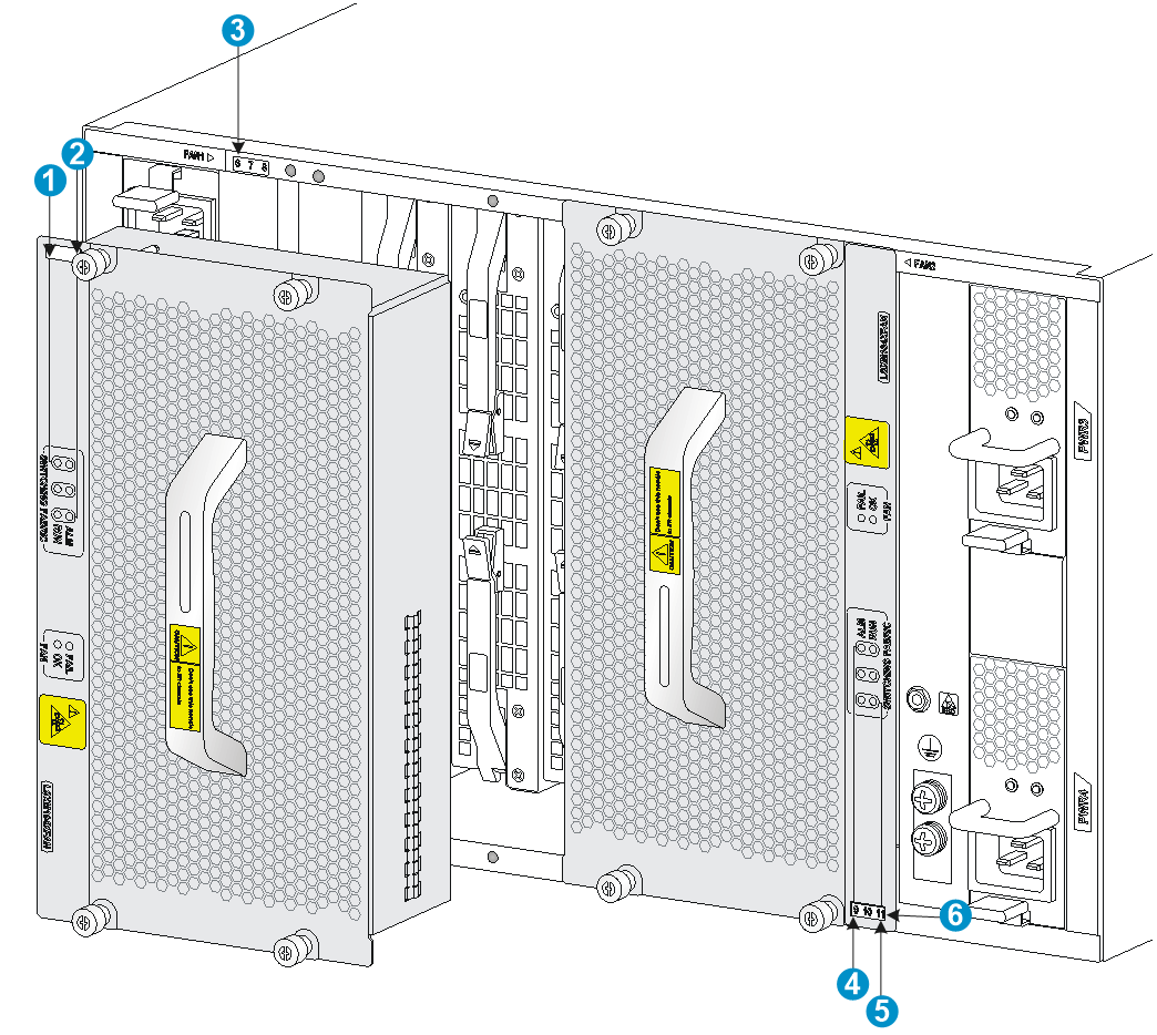
· On an S12504R fan tray, the extend lines of the fabric module LED pairs correspond to the fabric module the fan tray covers from left to right.
· For an S12508CR or S12516CR, the fan tray in the FAN5 slot covers only one fabric module. Only one of the two fabric module status LEDs on the fan tray is on.
Figure 3-3 Corresponding relations between the LEDs on S12504R fan trays and fabric module slots
|
(1) LEDs for the fabric module slot 6 |
(2) LEDs for the fabric module slot 8 |
|
(3) Fabric module slot number |
(4) LEDs for the fabric module slot 9 |
|
(5) LEDs for the fabric module slot 11 |
(6) Fabric module slot number |
Table 3-20 Description for fabric module status LEDs on an S12516R/S12508R/S12504R fan tray
|
RUN |
ALM |
Description |
|
Flashing (once per second) |
Off |
The fabric module is operating correctly. |
|
Off |
On |
The fabric module has failed. |
|
Flashing (once per second) |
On |
· The fabric module is loading software. · The fabric module is operating incorrectly. For example, the temperature exceeds the acceptable range. |
|
Off |
Off |
The fabric module has not started or is not powered on. |
|
On |
On |
The fabric module is booting. |
Table 3-21 Description for fabric module status LEDs on an S12516CR/S12508CR fan tray
|
LED status (RUN/ALM) |
Description |
|
Slow flashing green (0.5 Hz) |
The fabric module is operating correctly. |
|
Fast flashing green (4 Hz) |
The fabric module is loading software or is operating incorrectly. |
|
Steady red |
The fabric module is faulty. |
|
Off |
The fabric module has not started or is not powered on. |
Fan tray LEDs
A fan tray uses an OK LED and a FAIL LED to indicate its operating status.
Table 3-22 Fan tray LED description
|
OK |
FAIL |
Description |
|
On |
Off |
The fan tray is operating correctly. |
|
Off |
On |
The fan tray is faulty. |
|
Off |
Off |
The fan tray is not powered on. |
Power module LEDs
Each power module provides two LEDs to indicate its operating status.
Table 3-23 Power module LED description
|
LED |
Status |
Description |
|
PSR2400-54A/PSR3000-54A |
||
|
AC |
Off |
· No power is being input. · The power module is in self-protection state because of low input voltage. |
|
Green |
Power is being input correctly. |
|
|
DC |
Green |
Power is being output correctly. |
|
Red |
The power module is in self-protection state because of one of the following problems: · Output short-circuit. · Output overcurrent. · Output overvoltage. · Input under-voltage. · Remote poweroff. |
|
|
Orange |
An over-temperature alarm occurred on the power module. |
|
|
PSR2400-54D |
||
|
INPUT OK |
Off |
· No power is being input. · The power module is in self-protection state because of low input voltage. |
|
Green |
Power is being input correctly. |
|
|
OUTPUT OK |
Green |
Power is being output correctly. |
|
Red |
The power module is in self-protection state because of one of the following problems: · Output short-circuit. · Output overcurrent. · Output overvoltage. · Input under-voltage. · Remote poweroff. |
|
|
Orange |
An over-temperature alarm occurred on the power module. |
|
|
PSR3000-54AHD |
||
|
IN |
Off |
· No power is being input. · The power module is in self-protection state because of low input voltage. |
|
Green |
Power is being input correctly. |
|
|
OUT |
Green |
Power is being output correctly. |
|
Orange |
An over-temperature alarm occurred on the power module. |
|
|
Red |
The power module is in self-protection state because of one of the following problems: · Output overcurrent. · Output overvoltage. · Input under-voltage. · Over-temperature. · Remote poweroff. |
|
|
PSR2000B-54D/PSR3000B-54AHD |
||
|
IN |
Off |
No power input. |
|
Green |
Power is being input correctly. |
|
|
Red |
Input undervoltage or overvoltage or no power input. |
|
|
OUT |
Off |
No power input. |
|
Green |
Power is being output correctly. |
|
|
Red |
Output overvoltage, output overcurrent, or overtemperature protection state. |
|
|
PSR1800-56A |
||
|
AC |
Green |
Normal power input. |
|
Off |
Abnormal or no power input. |
|
|
DC |
Green |
Normal power output. |
|
Red |
Abnormal power output. |
|
|
Off |
No power output. |
|
|
PSR1800-56D |
||
|
IN |
Green |
Normal power input. |
|
Off |
Abnormal or no power input. |
|
|
OUT |
Green |
Normal power output. |
|
Red |
Abnormal power output. |
|
