- Table of Contents
-
- 07-MPLS Configuration Guide
- 00-Preface
- 01-Basic MPLS configuration
- 02-Static LSP configuration
- 03-LDP configuration
- 04-MPLS TE configuration
- 05-Static CRLSP configuration
- 06-RSVP configuration
- 07-Tunnel policy configuration
- 08-MPLS L3VPN configuration
- 09-MPLS L2VPN configuration
- 10-VPLS configuration
- 11-MPLS OAM configuration
- 12-MCE configuration
- 13-Static SR over MPLS configuration
- Related Documents
-
| Title | Size | Download |
|---|---|---|
| 13-Static SR over MPLS configuration | 236.55 KB |
Contents
Configuring static SR over MPLS
Restrictions and guidelines: static SR over MPLS configuration
Static SR over MPLS tasks at a glance
Prerequisites for static SR over MPLS
Configuring an adjacency segment
Binding a static SRLSP to an MPLS TE tunnel interface
Display and maintenance commands for static SRLSP
Static SRLSP configuration examples
Example: Configuring static SRLSPs by using the adjacency segment method
Example: Configuring static SRLSPs by using the prefix and adjacency segment methods
Configuring static SR over MPLS
About static SR over MPLS
About SR and SRLSP
Segment Routing (SR) is a source routing technology. The source node selects a path for the packets, and then encodes the path as a list of segments in the packets. Each segment is identified by the segment identifier (SID). The SR nodes forward the arriving packets based on the SIDs in the packets. Only the source node needs to maintain the path status.
There are the following types of segments:
· Prefix segment—SIDs are assigned to nodes based on destination address prefix. The nodes create prefix-specific forwarding entries.
· Adjacency segment—SIDs are assigned to nodes based on adjacency.
SR can operate with MPLS. In an MPLS network, SR uses MPLS labels as SIDs to forward packets on an LSP. Such an LSP is referred to as a segment routing label switched path (SRLSP).
SRLSPs are special CRLSPs established based on SR. An MPLS TE tunnel can contain one or multiple SRLSPs. The source node (ingress node of an MPLS TE tunnel) forwards packets that are routed to the MPLS TE tunnel interface through the SRLSPs.
How static SR over MPLS works
Static SR over MPLS provides the following methods for establishing a static SRLSP:
· Prefix segment method—Each node on the SRLSP has segment information for the destination IP address. The segment information is manually configured and includes the incoming label, outgoing label, and next hop.
· Adjacency segment method—Each node on the SRLSP has segment information for the adjacency to its neighbor. The segment information is manually configured and includes the incoming label and next hop. The label stack on the ingress node specifies all labels of the segments that the forwarding path traverses.
Prefix SID-based packet forwarding
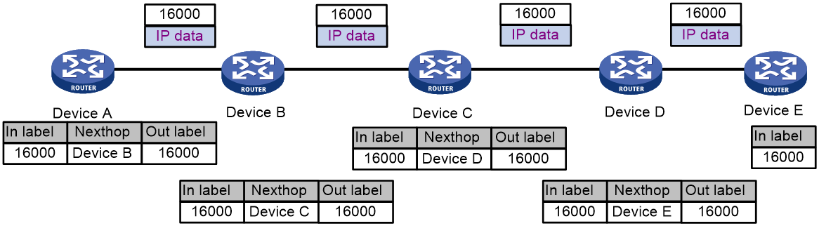
Figure 1 shows how static SRLSP forwards a packet when prefix SIDs (prefix labels) are used.
1. Ingress node Device A adds label 16000 (the prefix label of the destination IP address) to the packet and then forwards the packet to the next hop (Device B).
2. When transit node Device B receives the packet, it compares the label in the packet (label 16000) with the incoming label. The label matches the incoming label. Device B then performs the following operations:
a. Removes the label from the packet.
b. Adds the outgoing label (label 16000) to the packet.
c. Forwards the packet to the next hop (Device C).
3. Transit nodes Device C and Device D process the packet in the same way Device B does.
4. When egress node Device E receives the packet, it compares the label in the packet (label 16000) with the incoming label. The label matches the incoming label. Device E then removes the label and forwards the packet to the destination IP address.
Figure 1 Prefix SID-based packet forwarding
Adjacency SID-based packet forwarding
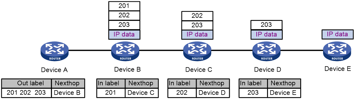
Figure 2 shows how static SRLSP forwards a packet when adjacency SIDs (adjacency labels) are used.
1. Ingress node Device A adds a label stack (201, 202, and 203) to the packet and then forwards it to the next hop (Device B).
The label stack lists labels of the adjacency segments in the order that the SRLSP traverses.
2. When transit node Device B receives the packet, it compares the top label in the packet (label 201) with the incoming label. The top label matches the incoming label. Device B then removes the top label from the packet and forwards the packet to the next hop (Device C).
3. When transit node Device C receives the packet, it compares the top label in the packet (label 202) with the incoming label. The top label matches the incoming label. Device C then removes the top label from the packet and forwards the packet to the next hop (Device D).
4. When transit node Device D receives the packet, it compares the top label in the packet (label 203) with the incoming label. The top label matches the incoming label. Device D then removes the top label from the packet and forwards the packet to the next hop (Device E).
5. When egress node Device E receives the packet, it forwards the packet to the destination IP address.
Figure 2 Adjacency SID-based packet forwarding
Prefix and adjacency SID-based packet forwarding
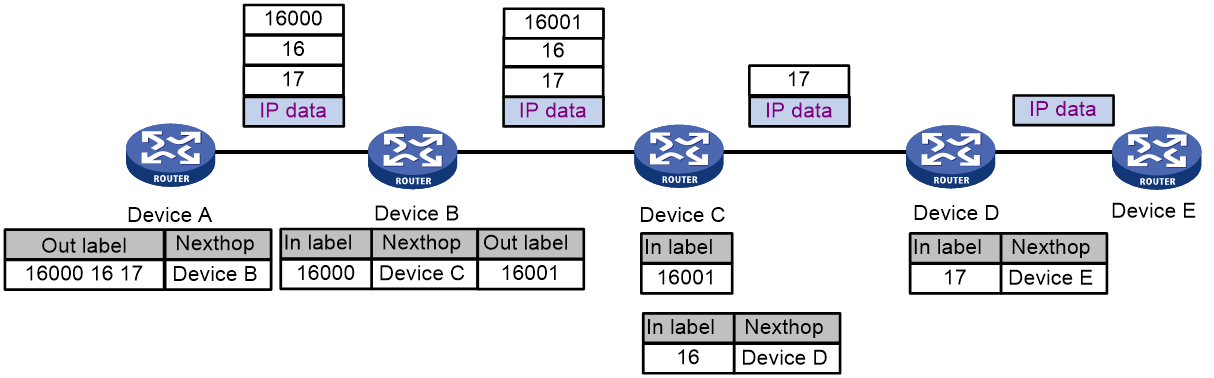
As shown in Figure 3, a static SRLSP with a label stack (16000, 16, and 17) has been established to Device E on Device A.
· A prefix segment is configured on Device A. The incoming label and outgoing label of the segment is 16000 and 16000, respectively. The next hop of the segment is Device B.
· A prefix segment is configured on Device B. The incoming label and outgoing label of the segment is 16000 and 16001, respectively. The next hop of the segment is Device C.
· A prefix segment and an adjacency segment are configured on Device C. The incoming label of the prefix segment is 16001. The incoming label of the adjacency segment is 16. The next hop of the adjacency segment is Device D.
· An adjacency segment is configured on Device D. The incoming label of the segment is 17 and the next hop of the segment is Device E.
A packet is forwarded over the SRLSP as follows:
1. Ingress node Device A adds a label stack (16000, 16, and 17) to the packet and then forwards the packet to the next hop (Device B).
The label stack lists labels of the segments in the order that the SRLSP traverses.
2. When Device B receives the packet, it compares the top label in the packet (label 16000) with the incoming label of the prefix segment. The top label matches the incoming label. Device B then performs the following operations:
a. Removes the top label from the packet.
b. Adds the outgoing label (label 16001) to the packet.
c. Forwards the packet to the next hop (Device C).
3. When Device C receives the packet, it performs the following operations:
a. Compares the top label (label 16001) with the incoming labels of the prefix and adjacency segments. The top label matches the incoming label of the prefix segment.
b. Removes the top label from the packet.
c. Compares the next label (label 16) with the incoming labels of the prefix and adjacency segments because the prefix label information does not include a next hop. The label matches the incoming label of the adjacency segment.
d. Removes the label from the packet.
e. Forwards the packet to the next hop (Device D) of the adjacency segment.
4. When Device D receives the packet, it compares the top label in the packet (label 17) with the incoming label. The top label matches the incoming label. Device D then removes the label from the packet and forwards the packet to the next hop (Device E).
5. When egress node Device E receives the packet, it forwards the packet to the destination IP address.
Figure 3 Prefix and adjacency SID-based packet forwarding
Protocols and standards
· draft-ietf-spring-segment-routing-mpls-00
· draft-ietf-spring-segment-routing-02
Restrictions and guidelines: static SR over MPLS configuration
The device does not support static SR over MPLS when it is operating in enhanced Layer 2 mode (set by the system-working-mode bridgee command).
Static SR over MPLS tasks at a glance
To configure static SR over MPLS, perform the following tasks:
1. Configuring prefix segments or adjacency segments for static SR
¡ Configuring an adjacency segment
¡ Configuring a prefix segment
You can configure both prefix and adjacency segments on a node.
Perform this task only on the ingress node of the MPLS TE tunnel.
3. Creating a tunnel interface, and specifying the tunnel destination address
Perform this task only on the ingress node of the MPLS TE tunnel. For more information, see "Configuring MPLS TE."
4. Binding a static SRLSP to an MPLS TE tunnel interface
Perform this task only on the ingress node of the MPLS TE tunnel.
5. Configuring static routing or PBR to direct traffic to the MPLS TE tunnel
Perform this task only on the ingress node of the MPLS TE tunnel. For more information, see "Configuring MPLS TE."
Prerequisites for static SR over MPLS
Before you configure static SR over MPLS, perform the following tasks:
· Determine the ingress node, transit nodes, and egress node of a static SRLSP.
· Determine the incoming label for the adjacency segment from a node to next hop of the node. Determine the incoming label for the destination IP address for the prefix segment on each node. On a device, a static SRLSP, a static LSP, and a static CRLSP cannot use the same incoming label.
· Enable MPLS on all nodes and interfaces that will participate in MPLS forwarding. For information about enabling MPLS, see "Configuring basic MPLS."
Configuring an adjacency segment
About adjacency segment configuration
Multiple static SRLSPs can share an adjacency segment.
Procedure
1. Enter system view.
system-view
2. Configure an adjacency segment.
static-sr-mpls adjacency adjacency-path-name in-label label-value { nexthop ip-address | outgoing-interface interface-type interface-number }
Do not specify a local public IP address as the next hop address when configuring an adjacency segment.
Configuring a prefix segment
About prefix segment configuration
Multiple static SRLSPs to the same destination can share a prefix segment.
Procedure
1. Enter system view.
system-view
2. Configure a prefix segment.
static-sr-mpls prefix prefix-path-name destination ip-address { mask | mask-length } in-label in-label-value [ { nexthop ip-address | outgoing-interface interface-type interface-number } out-label out-label-value ]
Do not specify a local public IP address as the next hop address when configuring a prefix segment.
Configuring a static SRLSP
1. Enter system view.
system-view
2. Configure a static SRLSP.
static-sr-mpls lsp lsp-name out-label out-label-value&<1-n>
For the S12500X-AF H cards, the value of n is 7. For the S12500X-AF F cards and the S12500-X and S9800 switches, the value of n is 4.
Binding a static SRLSP to an MPLS TE tunnel interface
1. Enter system view.
system-view
2. Enter MPLS TE tunnel interface view.
interface tunnel tunnel-number [ mode mpls-te ]
3. Set the MPLS TE tunnel establishment mode to static.
mpls te signaling static
By default, MPLS TE uses RSVP-TE to establish a tunnel.
4. Bind a static SRLSP to the MPLS TE tunnel interface.
mpls te static-sr-mpls lsp-name
By default, an MPLS TE tunnel does not use a static SRLSP.
Display and maintenance commands for static SRLSP
Execute display commands in any view.
|
Task |
Command |
|
Display static SRLSP and adjacency segment information. |
display mpls static-sr-mpls { [ lsp [ lsp-name ] | adjacency [ adjacency-path-name ] } |
|
Display prefix segment information. |
display mpls static-sr-mpls prefix [ path prefix-path-name | destination ip-address [ mask | mask-length ] ] |
Static SRLSP configuration examples
Example: Configuring static SRLSPs by using the adjacency segment method
Network configuration
As shown in Figure 4, Switch A, Switch B, Switch C, Switch D, Switch E, and Switch F run IS-IS.
Establish an MPLS TE tunnel over a static SRLSP from Switch A to Switch D to transmit data between the two IP networks. The static SRLSP traverses three segments: Switch A—Switch B, Switch B—Switch C, and Switch C—Switch D.
Establish an MPLS TE tunnel over a static SRLSP from Switch E to Switch F to transmit data between the IP networks. The static SRLSP traverses three segments: Switch E—Switch B, Switch B—Switch C, and Switch C—Switch F.
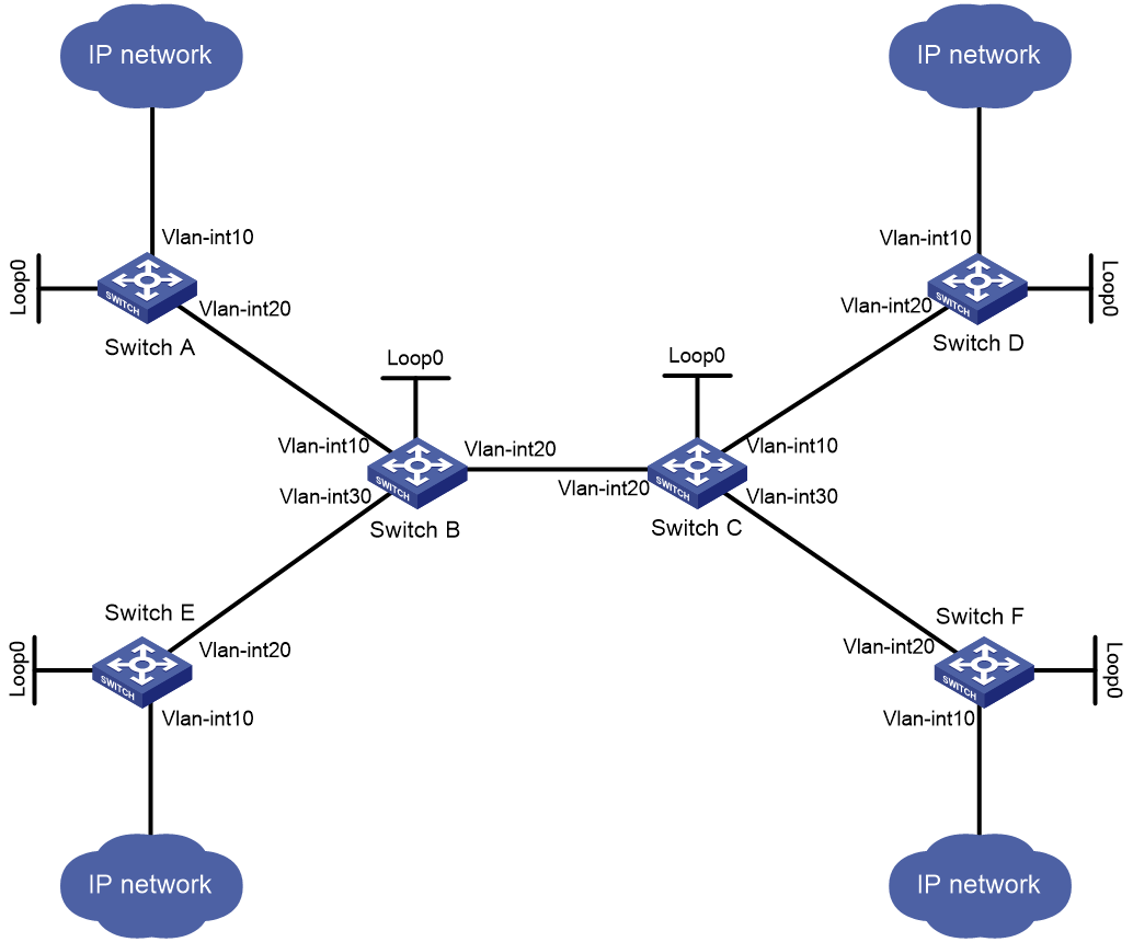
Table 1 Interface and IP address assignment
|
Device |
Interface |
IP address |
Device |
Interface |
IP address |
|
Switch A |
Loop0 |
1.1.1.9/32 |
Switch B |
Loop0 |
2.2.2.9/32 |
|
|
Vlan-int10 |
100.1.1.1/24 |
|
Vlan-int10 |
10.1.1.2/24 |
|
|
Vlan-int20 |
10.1.1.1/24 |
|
Vlan-int20 |
20.1.1.1/24 |
|
|
|
|
|
Vlan-int30 |
40.1.1.1/24 |
|
Switch C |
Loop0 |
3.3.3.9/32 |
Switch D |
Loop0 |
4.4.4.9/32 |
|
|
Vlan-int10 |
30.1.1.1/24 |
|
Vlan-int10 |
100.1.2.1/24 |
|
|
Vlan-int20 |
20.1.1.2/24 |
|
Vlan-int20 |
30.1.1.2/24 |
|
|
Vlan-int30 |
50.1.1.1/24 |
|
|
|
|
Switch E |
Loop0 |
5.5.5.9/32 |
Switch F |
Loop0 |
6.6.6.9/32 |
|
|
Vlan-int10 |
200.1.1.1/24 |
|
Vlan-int10 |
200.1.2.1/24 |
|
|
Vlan-int20 |
40.1.1.2/24 |
|
Vlan-int20 |
50.1.1.2/24 |
Procedure
|
|
IMPORTANT: By default, interfaces on the device are disabled (in ADM or Administratively Down state). To have an interface operate, you must use the undo shutdown command to enable that interface. |
1. Configure IP addresses and masks for interfaces. (Details not shown.)
2. Configure IS-IS to advertise interface addresses, including the loopback interface address. (Details not shown.)
3. Execute the display ip routing-table command on each switch to verify that the switches have learned the routes to one another, including the routes to the loopback interfaces. (Details not shown.)
4. Configure LSR IDs, and enable MPLS and MPLS TE:
# Configure Switch A.
<SwitchA> system-view
[SwitchA] mpls lsr-id 1.1.1.9
[SwitchA] mpls te
[SwitchA-te] quit
[SwitchA] interface vlan-interface 20
[SwitchA-Vlan-interface20] mpls enable
[SwitchA-Vlan-interface20] quit
# Configure Switch B.
<SwitchB> system-view
[SwitchB] mpls lsr-id 2.2.2.9
[SwitchB] mpls te
[SwitchB-te] quit
[SwitchB] interface vlan-interface 10
[SwitchB-Vlan-interface10] mpls enable
[SwitchB-Vlan-interface10] quit
[SwitchB] interface vlan-interface 20
[SwitchB-Vlan-interface20] mpls enable
[SwitchB-Vlan-interface20] quit
[SwitchB] interface vlan-interface 30
[SwitchB-Vlan-interface30] mpls enable
[SwitchB-Vlan-interface30] quit
# Configure Switch C.
<SwitchC> system-view
[SwitchC] mpls lsr-id 3.3.3.9
[SwitchC] mpls te
[SwitchC-te] quit
[SwitchC] interface vlan-interface 10
[SwitchC-Vlan-interface10] mpls enable
[SwitchC-Vlan-interface10] quit
[SwitchC] interface vlan-interface 20
[SwitchC-Vlan-interface20] mpls enable
[SwitchC-Vlan-interface20] quit
[SwitchC] interface vlan-interface 30
[SwitchC-Vlan-interface30] mpls enable
[SwitchC-Vlan-interface30] quit
# Configure Switch D.
<SwitchD> system-view
[SwitchD] mpls lsr-id 4.4.4.9
[SwitchD] mpls te
[SwitchD-te] quit
[SwitchD] interface vlan-interface 20
[SwitchD-Vlan-interface20] mpls enable
[SwitchD-Vlan-interface20] quit
# Configure Switch E.
<SwitchE> system-view
[SwitchE] mpls lsr-id 5.5.5.9
[SwitchE] mpls te
[SwitchE-te] quit
[SwitchE] interface vlan-interface 20
[SwitchE-Vlan-interface20] mpls enable
[SwitchE-Vlan-interface20] quit
# Configure Switch F.
<SwitchF> system-view
[SwitchF] mpls lsr-id 6.6.6.9
[SwitchF] mpls te
[SwitchF-te] quit
[SwitchF] interface vlan-interface 20
[SwitchF-Vlan-interface20] mpls enable
[SwitchF-Vlan-interface20] quit
5. Configure adjacency segments on the nodes:
# On Switch A, create adjacency segment adjacency-1, and bind incoming label 16 to the next hop address 10.1.1.2.
[SwitchA] static-sr-mpls adjacency adjacency-1 in-label 16 nexthop 10.1.1.2
# On Switch B, create adjacency segments adjacency-1, adjacency-2, and adjacency-3, and bind incoming labels 20, 21, and 22 to next hop addresses 10.1.1.1, 20.1.1.2, and 40.1.1.2, respectively.
[SwitchB] static-sr-mpls adjacency adjacency-1 in-label 20 nexthop 10.1.1.1
[SwitchB] static-sr-mpls adjacency adjacency-2 in-label 21 nexthop 20.1.1.2
[SwitchB] static-sr-mpls adjacency adjacency-3 in-label 22 nexthop 40.1.1.2
# On Switch C, create segments adjacency-1, adjacency-2, and adjacency-3, and bind incoming labels 30, 31, and 32 to next hop addresses 30.1.1.2, 50.1.1.2, and 20.1.1.1, respectively.
[SwitchC] static-sr-mpls adjacency adjacency-1 in-label 30 nexthop 30.1.1.2
[SwitchC] static-sr-mpls adjacency adjacency-2 in-label 31 nexthop 50.1.1.2
[SwitchC] static-sr-mpls adjacency adjacency-3 in-label 32 nexthop 20.1.1.1
# On Switch D, create adjacency segment adjacency-1, and bind incoming label 40 to the next hop address 30.1.1.1.
[SwitchD] static-sr-mpls adjacency adjacency-1 in-label 40 nexthop 30.1.1.1
# On Switch E, create adjacency segment adjacency-1, and bind incoming label 50 to the next hop address 40.1.1.1.
[SwitchE] static-sr-mpls adjacency adjacency-1 in-label 50 nexthop 40.1.1.1
# On Switch F, create adjacency segment adjacency-1, and bind incoming label 60 to the next hop address 50.1.1.1.
[SwitchF] static-sr-mpls adjacency adjacency-1 in-label 60 nexthop 50.1.1.1
6. Establish static SRLSPs:
# Configure Switch A as the ingress node of static SRLSP static-sr-lsp-1 and configure a label stack of [16, 21, 30].
[SwitchA] static-sr-mpls lsp static-sr-lsp-1 out-label 16 21 30
# Configure Switch E as the ingress node of static SRLSP static-sr-lsp-2 and configure a label stack of [50, 21, 31].
[SwitchE] static-sr-mpls lsp static-sr-lsp-2 out-label 50 21 31
7. Configure MPLS TE tunnels over static SRLSPs:
# On Switch A, establish static MPLS TE tunnel 0 to Switch D and specify the tunnel destination address as the LSR ID of Switch D. Bind static SRLSP static-sr-lsp-1 to MPLS TE tunnel interface 0.
[SwitchA] interface tunnel 0 mode mpls-te
[SwitchA-Tunnel0] ip address 6.1.1.1 255.255.255.0
[SwitchA-Tunnel0] destination 4.4.4.9
[SwitchA-Tunnel0] mpls te signaling static
[SwitchA-Tunnel0] mpls te static-sr-mpls static-sr-lsp-1
[SwitchA-Tunnel0] quit
# On Switch E, establish static MPLS TE tunnel 0 to Switch F and specify the tunnel destination address as the LSR ID of Switch F. Bind static SRLSP static-sr-lsp-2 to MPLS TE tunnel interface 0.
[SwitchE] interface tunnel 0 mode mpls-te
[SwitchE-Tunnel0] ip address 7.1.1.1 255.255.255.0
[SwitchE-Tunnel0] destination 6.6.6.9
[SwitchE-Tunnel0] mpls te signaling static
[SwitchE-Tunnel0] mpls te static-sr-mpls static-sr-lsp-2
[SwitchE-Tunnel0] quit
8. Create static routes to redirect traffic to MPLS TE tunnels.
# On Switch A, configure a static route to redirect traffic destined for 100.1.2.0/24 to MPLS TE tunnel 0.
[SwitchA] ip route-static 100.1.2.0 24 tunnel 0 preference 1
# On Switch E, configure a static route to redirect traffic destined for 200.1.2.0/24 to MPLS TE tunnel 0.
[SwitchE] ip route-static 200.1.2.0 24 tunnel 0 preference 1
Verifying the configuration
# Display the MPLS TE tunnel information on Switch A.
[SwitchA] display mpls te tunnel-interface
Tunnel Name : Tunnel 0
Tunnel State : Up (Main CRLSP up)
Tunnel Attributes :
LSP ID : 1 Tunnel ID : 0
Admin State : Normal
Ingress LSR ID : 1.1.1.9 Egress LSR ID : 4.4.4.9
Signaling : Static Static CRLSP Name : -
Static SRLSP Name : static-sr-lsp-1/-
Resv Style : -
Tunnel mode : -
Reverse-LSP name : -
Reverse-LSP LSR ID : - Reverse-LSP Tunnel ID: -
Class Type : - Tunnel Bandwidth : -
Reserved Bandwidth : -
Setup Priority : 0 Holding Priority : 0
Affinity Attr/Mask : -/-
Explicit Path : -
Backup Explicit Path : -
Metric Type : TE
Record Route : - Record Label : -
FRR Flag : - Bandwidth Protection : -
Backup Bandwidth Flag: - Backup Bandwidth Type: -
Backup Bandwidth : -
Bypass Tunnel : - Auto Created : -
Route Pinning : -
Retry Limit : 3 Retry Interval : 2 sec
Reoptimization : - Reoptimization Freq : -
Backup Type : - Backup LSP ID : -
Auto Bandwidth : - Auto Bandwidth Freq : -
Min Bandwidth : - Max Bandwidth : -
Collected Bandwidth : -
# Display the MPLS TE tunnel information on Switch E.
[SwitchE] display mpls te tunnel-interface
Tunnel Name : Tunnel 0
Tunnel State : Up (Main CRLSP up)
Tunnel Attributes :
LSP ID : 1 Tunnel ID : 0
Admin State : Normal
Ingress LSR ID : 5.5.5.9 Egress LSR ID : 6.6.6.9
Signaling : Static Static CRLSP Name : -
Static SRLSP Name : static-sr-lsp-2/-
Resv Style : -
Tunnel mode : -
Reverse-LSP name : -
Reverse-LSP LSR ID : - Reverse-LSP Tunnel ID: -
Class Type : - Tunnel Bandwidth : -
Reserved Bandwidth : -
Setup Priority : 0 Holding Priority : 0
Affinity Attr/Mask : -/-
Explicit Path : -
Backup Explicit Path : -
Metric Type : TE
Record Route : - Record Label : -
FRR Flag : - Bandwidth Protection : -
Backup Bandwidth Flag: - Backup Bandwidth Type: -
Backup Bandwidth : -
Bypass Tunnel : - Auto Created : -
Route Pinning : -
Retry Limit : 3 Retry Interval : 2 sec
Reoptimization : - Reoptimization Freq : -
Backup Type : - Backup LSP ID : -
Auto Bandwidth : - Auto Bandwidth Freq : -
Min Bandwidth : - Max Bandwidth : -
Collected Bandwidth : -
# Display static SRLSP establishment on each switch by using the display mpls lsp or display mpls static-sr-lsp command.
[SwitchA] display mpls lsp
FEC Proto In/Out Label Interface/Out NHLFE
1.1.1.9/0/1 StaticCR -/21 Vlan20
30
- StaticCR 16/- Vlan20
10.1.1.2 Local -/- Vlan20
Tunnel0 Local -/- NHLFE537
[SwitchB] display mpls lsp
FEC Proto In/Out Label Interface/Out NHLFE
- StaticCR 21/- Vlan20
20.1.1.2 Local -/- Vlan20
[SwitchC] display mpls lsp
FEC Proto In/Out Label Interface/Out NHLFE
- StaticCR 30/- Vlan10
- StaticCR 31/- Vlan30
30.1.1.2 Local -/- Vlan10
50.1.1.2 Local -/- Vlan30
Example: Configuring static SRLSPs by using the prefix and adjacency segment methods
Network configuration
As shown in Figure 5, Switch A, Switch B, Switch C, Switch D, and Switch E run IS-IS.
Establish an MPLS TE tunnel over a static SRLSP from Switch A to Switch D to transmit data between the two IP networks. The static SRLSP traverses three adjacency segments: Switch A—Switch B, Switch B—Switch C, and Switch C—Switch D.
Establish an MPLS TE tunnel over a static SRLSP from Switch A to Switch E to transmit data between the IP networks. The static SRLSP traverses three segments: Switch A—Switch B (adjacency segment), Switch B—Switch C (prefix segment), and Switch C—Switch E (adjacency segment).
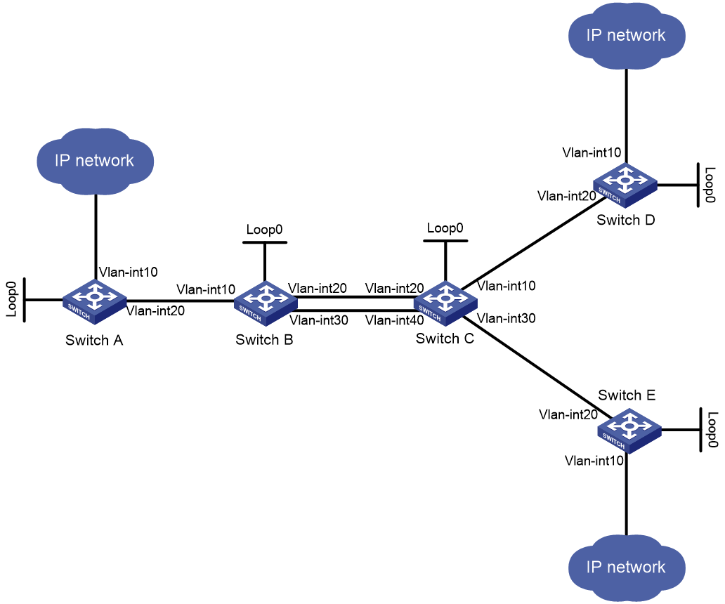
Table 2 Interface and IP address assignment
|
Device |
Interface |
IP address |
Device |
Interface |
IP address |
|
Switch A |
Loop0 |
1.1.1.9/32 |
Switch B |
Loop0 |
2.2.2.9/32 |
|
|
Vlan-int10 |
100.1.1.1/24 |
|
Vlan-int10 |
10.1.1.2/24 |
|
|
Vlan-int20 |
10.1.1.1/24 |
|
Vlan-int20 |
20.1.1.1/24 |
|
Switch C |
Loop0 |
3.3.3.9/32 |
|
Vlan-int30 |
60.1.1.1/24 |
|
|
Vlan-int10 |
30.1.1.1/24 |
Switch D |
Loop0 |
4.4.4.9/32 |
|
|
Vlan-int20 |
20.1.1.2/24 |
|
Vlan-int10 |
100.1.2.1/24 |
|
|
Vlan-int30 |
50.1.1.1/24 |
|
Vlan-int20 |
30.1.1.2/24 |
|
|
Vlan-int40 |
60.1.1.2/24 |
|
|
|
|
Switch E |
Loop0 |
5.5.5.9/32 |
|
|
|
|
|
Vlan-int10 |
200.1.2.1/24 |
|
|
|
|
|
Vlan-int20 |
50.1.1.2/24 |
|
|
|
Procedure
|
|
IMPORTANT: By default, interfaces on the device are disabled (in ADM or Administratively Down state). To have an interface operate, you must use the undo shutdown command to enable that interface. |
1. Configure IP addresses and masks for interfaces. (Details not shown.)
2. Configure IS-IS to advertise interface addresses, including the loopback interface address. (Details not shown.)
3. Execute the display ip routing-table command on each switch to verify that the switches have learned the routes to one another, including the routes to the loopback interfaces. (Details not shown.)
4. Configure LSR IDs, and enable MPLS and MPLS TE:
# Configure Switch A.
<SwitchA> system-view
[SwitchA] mpls lsr-id 1.1.1.9
[SwitchA] mpls te
[SwitchA-te] quit
[SwitchA] interface vlan-interface 20
[SwitchA-Vlan-interface20] mpls enable
[SwitchA-Vlan-interface20] quit
# Configure Switch B.
<SwitchB> system-view
[SwitchB] mpls lsr-id 2.2.2.9
[SwitchB] mpls te
[SwitchB-te] quit
[SwitchB] interface vlan-interface 10
[SwitchB-Vlan-interface10] mpls enable
[SwitchB-Vlan-interface10] quit
[SwitchB] interface vlan-interface 20
[SwitchB-Vlan-interface20] mpls enable
[SwitchB-Vlan-interface20] quit
[SwitchB] interface vlan-interface 30
[SwitchB-Vlan-interface30] mpls enable
[SwitchB-Vlan-interface30] quit
# Configure Switch C.
<SwitchC> system-view
[SwitchC] mpls lsr-id 3.3.3.9
[SwitchC] mpls te
[SwitchC-te] quit
[SwitchC] interface vlan-interface 10
[SwitchC-Vlan-interface10] mpls enable
[SwitchC-Vlan-interface10] quit
[SwitchC] interface vlan-interface 20
[SwitchC-Vlan-interface20] mpls enable
[SwitchC-Vlan-interface20] quit
[SwitchC] interface vlan-interface 30
[SwitchC-Vlan-interface30] mpls enable
[SwitchC-Vlan-interface30] quit
[SwitchC] interface vlan-interface 40
[SwitchC-Vlan-interface40] mpls enable
[SwitchC-Vlan-interface40] quit
# Configure Switch D.
<SwitchD> system-view
[SwitchD] mpls lsr-id 4.4.4.9
[SwitchD] mpls te
[SwitchD-te] quit
[SwitchD] interface vlan-interface 20
[SwitchD-Vlan-interface20] mpls enable
[SwitchD-Vlan-interface20] quit
# Configure Switch E.
<SwitchE> system-view
[SwitchE] mpls lsr-id 5.5.5.9
[SwitchE] mpls te
[SwitchE-te] quit
[SwitchE] interface vlan-interface 20
[SwitchE-Vlan-interface20] mpls enable
[SwitchE-Vlan-interface20] quit
5. Configure adjacency and prefix segments on the nodes:
# On Switch A, create adjacency segment adjacency-1, and bind incoming label 16 to the next hop address 10.1.1.2.
[SwitchA] static-sr-mpls adjacency adjacency-1 in-label 16 nexthop 10.1.1.2
# On Switch B, create adjacency segment adjacency-2, and bind incoming label 21 to next hop address 20.1.1.2.
[SwitchB] static-sr-mpls adjacency adjacency-2 in-label 21 nexthop 20.1.1.2
# On Switch B, create prefix segments named prefix-1 to destination IP address 5.5.5.9, bind incoming label 16000 to next hop addresses 20.1.1.2 and 60.1.1.2, and specify the outgoing label as 16001.
[SwitchB] static-sr-mpls prefix prefix-1 destination 5.5.5.9 32 in-label 16000 nexthop 20.1.1.2 out-label 16001
[SwitchB] static-sr-mpls prefix prefix-1 destination 5.5.5.9 32 in-label 16000 nexthop 60.1.1.2 out-label 16001
# On Switch C, create adjacency segment adjacency-1, and bind incoming label 30 to next hop address 30.1.1.2. Create adjacency segment adjacency-2, and bind incoming label 31 to next hop address 50.1.1.2.
[SwitchC] static-sr-mpls adjacency adjacency-1 in-label 30 nexthop 30.1.1.2
[SwitchC] static-sr-mpls adjacency adjacency-2 in-label 31 nexthop 50.1.1.2
# On Switch C, create prefix segment named prefix-1 to destination IP address 5.5.5.9, and specify the incoming label as 16001.
[SwitchC] static-sr-mpls prefix prefix-1 destination 5.5.5.9 32 in-label 16001
6. On Switch A, establish static SRLSP static-sr-lsp-1 to Switch D and static SRLSP static-sr-lsp-2 to Switch E:
# Configure Switch A as the ingress node of static SRLSP static-sr-lsp-1 and configure a label stack of [16, 21, 30].
[SwitchA] static-sr-mpls lsp static-sr-lsp-1 out-label 16 21 30
# Configure Switch A as the ingress node of static SRLSP static-sr-lsp-2 and configure a label stack of [16, 16000, 31].
[SwitchA] static-sr-mpls lsp static-sr-lsp-2 out-label 16 16000 31
7. Configure MPLS TE tunnels over static SRLSPs on Switch A:
# Establish static MPLS TE tunnel 0 to Switch D and specify the tunnel destination address as the LSR ID of Switch D. Bind static SRLSP static-sr-lsp-1 to MPLS TE tunnel interface 0.
[SwitchA] interface tunnel 0 mode mpls-te
[SwitchA-Tunnel0] ip address 6.1.1.1 255.255.255.0
[SwitchA-Tunnel0] destination 4.4.4.9
[SwitchA-Tunnel0] mpls te signaling static
[SwitchA-Tunnel0] mpls te static-sr-mpls static-sr-lsp-1
[SwitchA-Tunnel0] quit
# Establish static MPLS TE tunnel 1 to Switch E and specify the tunnel destination address as the LSR ID of Switch E. Bind static SRLSP static-sr-lsp-2 to MPLS TE tunnel interface 1.
[SwitchA] interface tunnel 1 mode mpls-te
[SwitchA-Tunnel1] ip address 7.1.1.1 255.255.255.0
[SwitchA-Tunnel1] destination 5.5.5.9
[SwitchA-Tunnel1] mpls te signaling static
[SwitchA-Tunnel1] mpls te static-sr-mpls static-sr-lsp-2
[SwitchA-Tunnel1] quit
8. On Switch A, configure two static routes to direct traffic destined for 100.1.2.0/24 and 200.1.2.0/24 to MPLS TE tunnel 0 and tunnel 1, respectively.
[SwitchA] ip route-static 100.1.2.0 24 tunnel 0 preference 1
[SwitchA] ip route-static 200.1.2.0 24 tunnel 1 preference 1
Verifying the configuration
# Display the MPLS TE tunnel information on Switch A.
[SwitchA] display mpls te tunnel-interface
Tunnel Name : Tunnel 0
Tunnel State : Up (Main CRLSP up)
Tunnel Attributes :
LSP ID : 1 Tunnel ID : 0
Admin State : Normal
Ingress LSR ID : 1.1.1.9 Egress LSR ID : 4.4.4.9
Signaling : Static Static CRLSP Name : -
Static SRLSP Name : static-sr-lsp-1/-
Signaling : Static Static CRLSP Name : -
Resv Style : -
Tunnel mode : -
Reverse-LSP name : -
Reverse-LSP LSR ID : - Reverse-LSP Tunnel ID: -
Class Type : - Tunnel Bandwidth : -
Reserved Bandwidth : -
Setup Priority : 0 Holding Priority : 0
Affinity Attr/Mask : -/-
Explicit Path : -
Backup Explicit Path : -
Metric Type : TE
Record Route : - Record Label : -
FRR Flag : - Backup Bandwidth Flag: -
Backup Bandwidth Flag: - Backup Bandwidth Type: -
Backup Bandwidth : -
Bypass Tunnel : - Auto Created : -
Route Pinning : -
Retry Limit : 3 Retry Interval : 2 sec
Reoptimization : - Reoptimization Freq : -
Backup Type : - Backup LSP ID : -
Auto Bandwidth : - Auto Bandwidth Freq : -
Min Bandwidth : - Max Bandwidth : -
Collected Bandwidth : -
Tunnel Name : Tunnel 1
Tunnel State : Up (Main CRLSP up)
Tunnel Attributes :
LSP ID : 1 Tunnel ID : 1
Admin State : Normal
Ingress LSR ID : 1.1.1.9 Egress LSR ID : 5.5.5.9
Signaling : Static Static CRLSP Name : -
Static SRLSP Name : static-sr-lsp-2/-
Resv Style : -
Tunnel mode : -
Reverse-LSP name : -
Reverse-LSP LSR ID : - Reverse-LSP Tunnel ID: -
Class Type : - Tunnel Bandwidth : -
Reserved Bandwidth : -
Setup Priority : 0 Holding Priority : 0
Affinity Attr/Mask : -/-
Explicit Path : -
Backup Explicit Path : -
Metric Type : TE
Record Route : - Record Label : -
FRR Flag : - Bandwidth Protection : -
Backup Bandwidth Flag: - Backup Bandwidth Type: -
Backup Bandwidth : -
Bypass Tunnel : - Auto Created : -
Route Pinning : -
Retry Limit : 3 Retry Interval : 2 sec
Reoptimization : - Reoptimization Freq : -
Backup Type : - Backup LSP ID : -
Auto Bandwidth : - Auto Bandwidth Freq : -
Min Bandwidth : - Max Bandwidth : -
Collected Bandwidth : -
# Display static SRLSP establishment on each switch by using the display mpls lsp or display mpls static-sr-lsp command.
[SwitchA] display mpls lsp
FEC Proto In/Out Label Interface/Out NHLFE
1.1.1.9/0/46565 StaticCR -/21 Vlan20
30
1.1.1.9/1/46565 StaticCR -/16000 Vlan20
31
- StaticCR 16/- Vlan20
10.1.1.2 Local -/- Vlan20
Tunnel0 Local -/- NHLFE1
Tunnel1 Local -/- NHLFE2
[SwitchB] display mpls lsp
FEC Proto In/Out Label Interface/Out NHLFE
5.5.5.9/32 StaticCR 16000/16001 Vlan20
5.5.5.9/32 StaticCR 16000/16001 Vlan30
- StaticCR 21/- Vlan20
20.1.1.2 Local -/- Vlan20
60.1.1.2 Local -/- Vlan30
[SwitchC] display mpls lsp
FEC Proto In/Out Label Interface/Out NHLFE
5.5.5.9/32 StaticCR 16001/- -
- StaticCR 30/- Vlan10
- StaticCR 31/- Vlan30
30.1.1.2 Local -/- Vlan10
50.1.1.2 Local -/- Vlan30
