- Table of Contents
- Related Documents
-
| Title | Size | Download |
|---|---|---|
| 02-MDC configuration | 183.52 KB |
Contents
Default MDC and non-default MDCs
Licensing requirements for MDC
Restrictions and guidelines: MDC configuration
MDC configuration tasks at a glance
Assigning hardware resources to an MDC
About assigning hardware resources
Assigning physical interfaces and LPUs to MDCs
Specifying a CPU weight for an MDC
Specifying a memory space percentage for an MDC
Display and maintenance commands for MDC
Example: Configuring MDCs (in standalone mode)
Example: Configuring MDCs (in IRF mode)
Configuring MDCs
About MDC
The Multitenant Device Context (MDC) technology can partition a physical device or an IRF fabric into multiple logical devices. Each of the logical devices is called an MDC.
MDC advantages
Each MDC uses its own hardware and software resources, runs independently of other MDCs, and provides services for its own customer. Creating, starting, rebooting, or deleting an MDC does not affect any other MDCs.
From the user's perspective, an MDC is a standalone physical device. MDCs on the same physical device are isolated from each other.
For an administrator, the MDC technology can help reduce costs and improve network resource efficiency. To add a new branch on the network, you only need to create an additional MDC. To manage MDCs, you only need to log in to the physical device.
MDC applications
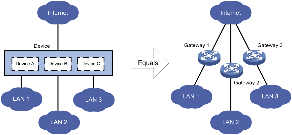
As shown in Figure 1, LAN 1, LAN 2, and LAN 3 are three companies' LANs. To provide access service for the three companies, you can deploy a single physical device and configure an MDC for each company on the device. Then, the administrators of each company can log in only to their own MDC to maintain their own network, without affecting any other MDC or network. The effect equals deploying a separate gateway for each company.
Default MDC and non-default MDCs
A device supporting MDCs is called the default MDC (for example, Device in Figure 1). The default MDC always uses the name Admin and the ID 1. You cannot delete it or change its name or ID.
When you log in to the physical device, you are logged in to the default MDC. Configuring the physical device is the same as configuring the default MDC.
On the default MDC, you can perform the following tasks:
· Manage the entire physical device.
· Create and delete non-default MDCs (for example, Device A, Device B, and Device C in Figure 1).
· Assign resources to non-default MDCs. These resources include interfaces, CPU resources, and memory space.
No MDCs can be created on a non-default MDC. Administrators of non-default MDCs can manage and maintain only their respective MDCs.
A non-default MDC can use only the resources assigned to it. It cannot use the resources assigned to other MDCs or the remaining resources on the physical device. Resources that are not assigned to any non-default MDC belong to the default MDC.
Unless otherwise stated, the term "MDC" refers to a non-default MDC.
Interface management
All interfaces belong to the default MDC by default. You can assign physical interfaces and LPUs to a non-default MDC.
The following physical interfaces always belong to the default MDC and cannot be assigned to a non-default MDC:
· Console port.
· Physical management Ethernet interfaces.
When you create an MDC, the system automatically creates one virtual management Ethernet interface for each physical management Ethernet interface on the MDC. A virtual management Ethernet interface uses the same interface number, physical port, and link as its corresponding physical management Ethernet interface. You can assign IP addresses to the virtual management Ethernet interfaces for access to the MDC. The IP addresses for the virtual management Ethernet interfaces can belong to different subnets.
You can use the shutdown command to shut down management Ethernet interfaces only on the default MDC.
Licensing requirements for MDC
MDC requires a license to run on the device. If no license is installed or the license expires, you cannot create, start, or use non-default MDCs. For more information about licenses, see "Managing licenses."
Restrictions and guidelines: MDC configuration
You can assign hardware resources to MDCs before or after you start the MDCs. As a best practice, assign MDCs resources before starting them.
To configure MDCs for a device that you want to add to an IRF fabric, add the device to the IRF fabric before configuring MDCs. After a device joins an IRF fabric, it reboots and loads the master's configuration instead of its own.
To configure both BFD MAD for a VLAN interface and MDCs, perform the following tasks:
¡ Configure IRF physical interfaces and BFD MAD for the VLAN interface on the default MDC.
¡ Make sure BFD MAD is not configured for a VLAN or VLAN interface on any non-default MDC.
MDC configuration tasks at a glance
To configure an MDC, perform the following tasks:
3. Assigning hardware resources to an MDC
¡ Assigning physical interfaces and LPUs to MDCs
¡ Specifying a CPU weight for an MDC
¡ Specifying a memory space percentage for an MDC
5. (Optional.) Returning to the default MDC
6. (Optional.) Deleting an MDC
Creating an MDC
About creating an MDC
Creating an MDC is equivalent to setting up a new device. A created MDC is not initialized or started.
Procedure
1. Enter system view.
system-view
2. Create an MDC.
mdc mdc-name [ id mdc-id ]
By default, a default MDC exists. The MDC name is Admin and the MDC ID is 1.
The default MDC is system defined. You cannot delete it.
Starting an MDC
About starting an MDC
An MDC starts to operate after being started.
Restrictions and guidelines
After the MDC starts up, use the display mdc resource command to identify the minimum memory space requirements for the MDC.
Procedure
1. Enter system view.
system-view
2. Enter MDC view.
mdc mdc-name [ id mdc-id ]
3. Start the MDC.
mdc start
The MDC starts up and starts the automatic configuration process.
4. Return to system view.
quit
5. Use the switchto mdc command to log in to the MDC and verify that the automatic configuration process is completed.
If the automatic configuration failed, stop the automatic configuration process as prompted. For more information about automatic configuration, see "Using automatic configuration."
Assigning hardware resources to an MDC
About assigning hardware resources
When you create an MDC, the system automatically assigns resources to the MDC, including CPU resources and memory space. You can adjust the resource allocations as required.
An MDC needs interfaces to forward packets. The system does not automatically assign LPUs or interfaces to MDCs. For an MDC to forward traffic, you must assign interfaces and LPUs to MDCs.
Assigning physical interfaces and LPUs to MDCs
Restrictions and guidelines for both standalone and IRF modes
· Make sure no other users are configuring an interface before you assign the interface to or reclaim the interface from an MDC.
· Interfaces on LPUs are grouped. The interfaces in a group must be assigned to or removed from the same MDC at the same time. Interface grouping varies by LPU model.
· Different groups of interfaces on an LPU can be assigned to different MDCs. You must assign the LPU to the MDCs.
· An interface can be assigned to only one MDC.
· Make sure an interface to be assigned to a non-default MDC belongs to the default MDC. To assign an interface that belongs to one non-default MDC to another non-default MDC, you must reclaim the interface first.
· To assign physical interfaces to an MDC, you must reclaim the LPUs where the physical interfaces reside from all MDCs, including the default MDC.
Restrictions and guidelines specific for IRF mode
· Each chassis must be installed with a minimum of two LPUs that support IRF physical interfaces. As a best practice, establish a minimum of two IRF links that use different LPUs on each chassis. To avoid IRF fabric split, make sure each member device always has a minimum of one IRF link in up state.
· To remove an LPU that holds the IRF physical interface of a non-default MDC, first complete the following tasks:
a. Remove the IRF physical interface configuration for the LPU.
b. Use the save command to save the running configuration.
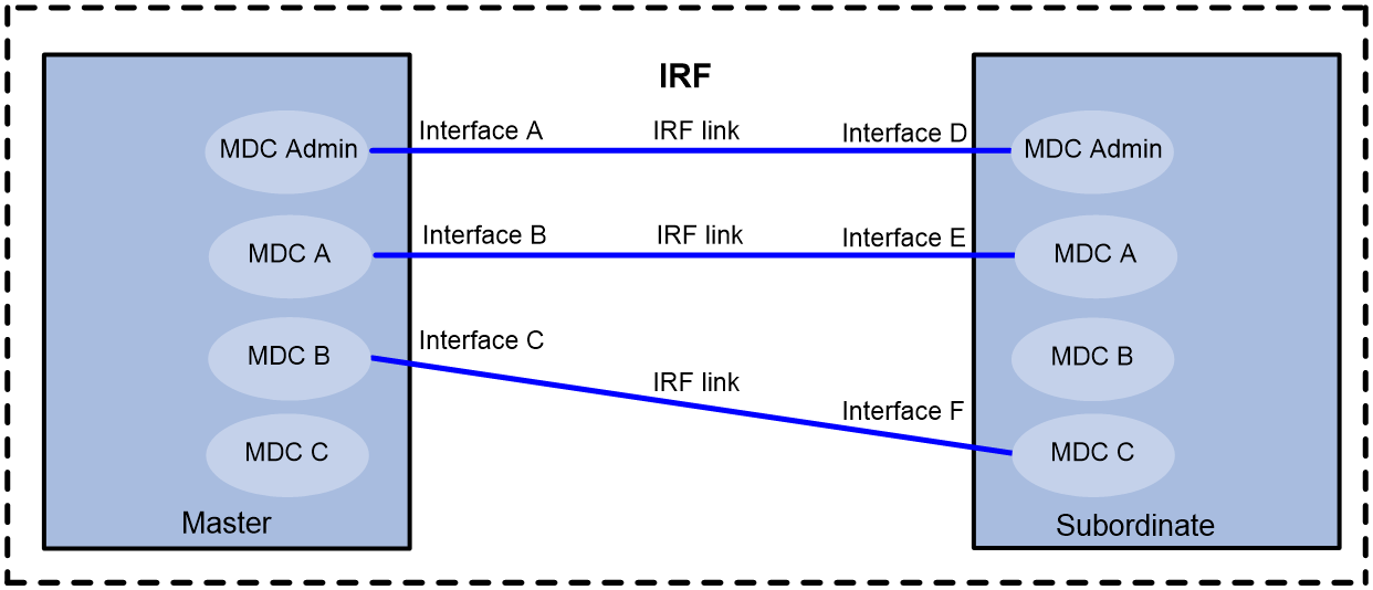
· The administrator of a non-default MDC can change the settings of an IRF physical interface that is assigned to the MDC. As a best practice, leave IRF physical interfaces to the default MDC. If you have to assign IRF physical interfaces to a non-default MDC, the two IRF physical interfaces of an IRF link can belong to the same MDC or different MDCs, as shown in Figure 2.
· You must remove the binding of an IRF physical interface to the IRF port before you can perform any of the following tasks:
¡ Assign the IRF physical interface to the default MDC or a non-default MDC.
¡ Reclaim the IRF physical interface from the default MDC or a non-default MDC.
· Assigning an IRF physical interface to or reclaiming an IRF physical interface from the default MDC or a non-default MDC causes the following problems:
¡ The IRF configuration on the interface is lost.
¡ The IRF link is closed.
To avoid IRF fabric split, make sure each member device always has a minimum of one IRF link in up state.
Restrictions and guidelines for interface configuration
Assigning or reclaiming a physical interface restores the settings of the interface to the defaults.
To configure parameters for a physical interface that has been assigned to an MDC, you must log in to the MDC.
Restrictions and guidelines for subcards
If you install a subcard on an LPU after assigning the LPU to a non-default MDC, the subcard cannot start up correctly. To install a subcard on an LPU after assigning the LPU to a non-default MDC, you must perform the following tasks:
1. Reclaim the LPU and the interfaces on the LPU.
2. Install the subcard.
3. Assign the LPU to the MDC again.
After you assign an LPU with subcards to a non-default MDC, you must replace a failed subcard on the LPU with a subcard of the same model. To use a subcard of a different model, you must perform the following tasks:
1. Reclaim the LPU and the interfaces on the LPU.
2. Replace the failed subcard.
3. Assign the LPU and the interfaces on the LPU to the MDC again.
Configuration considerations
Before assigning physical interfaces and LPUs to MDCs, determine the following items:
· Number of MDCs.
· Number of physical interfaces that each MDC needs.
· Interface numbers of the physical interfaces to be assigned to MDCs.
· Location of each LPU that holds the physical interfaces to be assigned.
Procedure
1. Determine the MDC requirements, including:
¡ Number of physical interfaces that each MDC needs.
¡ Interface numbers of the physical interfaces to be assigned to MDCs.
¡ Location of each LPU that holds the physical interfaces to be assigned.
2. Enter system view.
system-view
3. Enter the MDC view of the default MDC.
mdc Admin
4. Display the running configuration in the MDC view.
display this
If the undo location command is not displayed for an LPU that you want to assign to a non-default MDC, the LPU belongs to the default MDC. Use the undo location command to reclaim the LPU from the default MDC.
5. Return to system view.
quit
6. Enter the MDC view for the MDC to which you want to assign physical interfaces.
mdc mdc-name [ id mdc-id ]
7. Display the running configuration in the MDC view.
display this
If the location command is displayed for an LPU that you want to assign to the MDC, use the undo location command to reclaim the LPU from the MDC.
8. Assign physical interfaces to the MDC.
allocate interface interface-list
By default, all physical interfaces belong to the default MDC. A non-default MDC cannot use any physical interfaces.
To assign multiple physical interfaces to an MDC, specify the interfaces for the interface-list argument or execute this command multiple times.
9. Assign an LPU to the MDC.
In standalone mode:
location slot slot-number
In IRF mode:
location chassis chassis-number slot slot-number
By default, all LPUs belong to the default MDC. A non-default MDC cannot use any LPUs.
Assign an LPU to an MDC only if interfaces on the LPU have been assigned to the MDC.
Specifying a CPU weight for an MDC
About specifying CPU weights
To ensure correct operation of all MDCs, assign them CPU weights. All MDCs authorized to use the same LPU share the CPU of the LPU. If one MDC occupies too many of the CPU resources, the other MDCs might not be able to operate.
The number of CPU resources an MDC can use depends on the percentage of its CPU weight among the CPU weights of all MDCs that share the same CPU. For example, if three MDCs share the same CPU, setting their weights to 10, 10, and 5 is equivalent to setting their weights to 2, 2, and 1.
· The two MDCs with the same weight can use the CPU for approximately the same period of time.
· The third MDC can use the CPU for approximately half of the time for each of the other two MDCs.
The CPU weight specified for an MDC takes effect on all MPUs and all LPUs assigned to the MDC.
Procedure
1. Enter system view.
system-view
2. Enter MDC view.
mdc mdc-name [ id mdc-id ]
3. Specify a CPU weight for the MDC.
limit-resource cpu weight weight-value
The defaults are as follows:
¡ The default MDC has a CPU weight of 10 on each MPU and each LPU.
¡ Each non-default MDC has a CPU weight of 10 on each MPU and each assigned LPU.
The CPU weight for the default MDC is fixed at 10 and cannot be changed.
Specifying a memory space percentage for an MDC
About specifying memory space percentages
The MDCs on a device share and compete for the system memory space. If an MDC occupies too much memory space, the other MDCs might not be able to operate correctly. To avoid this problem, specify a memory space percentage for each MDC.
Prerequisites
Before you specify a memory space percentage for an MDC, use the display mdc resource command to view how much memory space the MDC is using. Make sure the memory space you assign to an MDC is sufficient for the MDC to operate correctly.
The amount of memory space assigned to an MDC must be greater than the amount of memory space the MDC is using. As a best practice, execute the display mdc resource command after the MDC starts up to identify the minimum memory space requirements.
Procedure
1. Display the memory space usage of the MDC.
In standalone mode:
display mdc [ name mdc-name ] resource [ memory ] [ slot slot-number ]
In IRF mode:
display mdc [ name mdc-name ] resource [ memory ] [ chassis chassis-number slot slot-number ]
This command is available in any view.
2. Enter system view.
system-view
3. Enter MDC view.
mdc mdc-name [ id mdc-id ]
4. Specify a memory space percentage for the MDC.
In standalone mode:
limit-resource memory slot slot-number ratio limit-ratio
In IRF mode:
limit-resource memory chassis chassis-number slot slot-number ratio limit-ratio
By default, all MDCs share the memory space in the system, and an MDC can use all free memory space in the system.
Accessing an MDC
About accessing an MDC
This feature enables you to log in to a non-default MDC from the system view of the default MDC.
Restrictions and guidelines
This feature provides the only method for you to access an MDC for the first time.
After using this feature to access an MDC, you can perform the following tasks to allow the administrator of the MDC to log in to the MDC by using Telnet or SSH:
· Assign an IP address to the management Ethernet interface.
· Create a VLAN interface on the MDC and assign an IP address to the interface.
· Make sure the MDC and the configuration terminal of the administrator of the MDC can reach each other.
Procedure
1. Enter system view.
system-view
2. Log in to an MDC.
switchto mdc mdc-name
You can use this command to log in only to an MDC that is in active state.
Returning to the default MDC
About returning to the default MDC
Use this feature to return from the user view of a non-default MDC to the system view of the default MDC.
Procedure
To return from the user view of a non-default MDC to the system view of the default MDC, use one of the following commands:
· switchback
· quit
Deleting an MDC
Restrictions and guidelines
When you delete an MDC, you must follow the procedure in this task so the resources in that MDC can be successfully reclaimed for reassignment.
Procedure
1. Enter system view.
system-view
2. Enter MDC view.
mdc mdc-name [ id mdc-id ]
3. Display the running configuration in the MDC view.
display this
4. Stop the MDC
undo mdc start
5. Display whether the MDC has IRF physical interfaces.
display irf link
If the MDC has IRF physical interfaces, use the undo port group command to remove the binding of physical interfaces to IRF ports.
6. Reclaim the LPUs assigned to the MDC.
undo location
7. Reclaim the physical interfaces assigned to the MDC.
undo allocate interface
8. Delete the MDC.
undo mdc
Display and maintenance commands for MDC
Execute display commands in any view on the default MDC:
|
Task |
Command |
|
Display MDCs and their status information. |
display mdc [ name mdc-name ] |
|
Display the interfaces of MDCs. |
display mdc [ name mdc-name ] interface |
|
Display the CPU and memory space usage of MDCs. |
In standalone mode: display mdc [ name mdc-name ] resource [ cpu | memory ] [ slot slot-number ] In IRF mode: display mdc [ name mdc-name ] resource [ cpu | memory ] [ chassis chassis-number slot slot-number ] |
Execute display commands in any view on a non-default MDC:
|
Task |
Command |
|
Display the ID, name, and status of the MDC. |
display mdc |
|
Display the interfaces of the MDC. |
display mdc interface |
|
Display the CPU and memory space usage of the MDC. |
In standalone mode: display mdc resource [ cpu | memory ] [ slot slot-number ] In IRF mode: display mdc resource [ cpu | memory ] [ chassis chassis-number slot slot-number ] |
MDC configuration examples
Example: Configuring MDCs (in standalone mode)
Network configuration
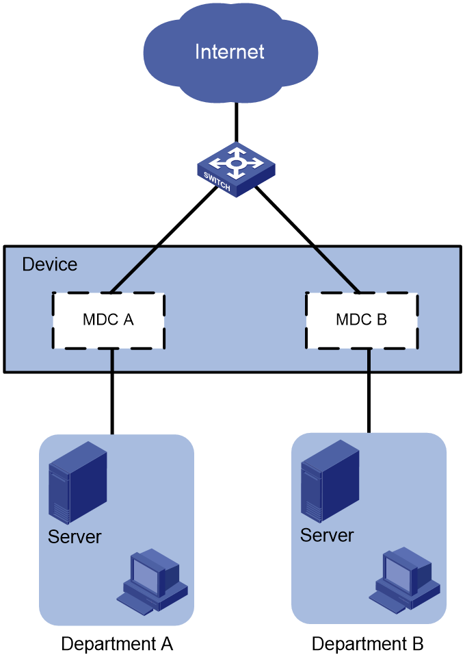
As shown in Figure 3, two departments need to use the device to access the Internet.
Configure two MDCs on the device to meet the Internet access requirements of two departments.
Procedure
|
|
IMPORTANT: By default, interfaces on the device are disabled (in ADM or Administratively Down state). To have an interface operate, you must use the undo shutdown command to enable that interface. |
1. Create and configure MDCs:
# Create MDCA for Department A.
<Device> system-view
[Device] mdc MDCA
It will take some time to create MDC...
MDC created successfully.
[Device-mdc-2-MDCA] quit
# Create MDCB for Department B.
[Device] mdc MDCB
It will take some time to create MDC...
MDC created successfully.
[Device-mdc-3-MDCB] quit
# Reclaim the LPU in slot 2 from the default MDC.
[Device] mdc Admin
[Device-mdc-1-Admin] undo location slot 2
The configuration associated with the specified slot of MDC will be lost. Continue? [Y/N]:y
[Device-mdc-1-Admin] quit
# Assign interfaces Ten-GigabitEthernet 2/0/1 through Ten-GigabitEthernet 2/0/24 to MDCA.
[Device] mdc MDCA
[Device-mdc-2-MDCA] allocate interface ten-gigabitethernet 2/0/1 to ten-gigabitethernet 2/0/24
Configuration of the interfaces will be lost. Continue? [Y/N]:y
Execute the location slot command in this view to make the configuration take effect.
[Device-mdc-2-MDCA] quit
# Authorize MDCA to use the LPU in slot 2.
[Device-mdc-2-MDCA] location slot 2
# Set the CPU weight to 5 for MDCA.
[Device-mdc-2-MDCA] limit-resource cpu weight 5
# Start MDCA.
[Device-mdc-2-MDCA] mdc start
It will take some time to start MDC...
MDC started successfully.
[Device-mdc-2-MDCA] quit
# Assign interfaces Ten-GigabitEthernet 2/0/25 through Ten-GigabitEthernet 2/0/48 to MDCB.
[Device] mdc MDCB
[Device-mdc-3-MDCB] allocate interface ten-gigabitethernet 2/0/25 to ten-gigabitethernet 2/0/48
Configuration of the interfaces will be lost. Continue? [Y/N]:y
Execute the location slot command in this view to make the configuration take effect.
# Authorize MDCB to use the LPU in slot 2.
[Device-mdc-3-MDCB] location slot 2
# Set the CPU weight to 5 for MDCB.
[Device-mdc-3-MDCB] limit-resource cpu weight 5
# Start MDCB.
[Device-mdc-3-MDCB] mdc start
It will take some time to start MDC...
MDC started successfully.
[Device-mdc-3-MDCB] quit
2. Configure the management Ethernet interface for MDCA:
# Log in to MDCA from the default MDC. Press Ctrl+D as prompted to access the CLI of MDCA.
[Device] switchto mdc MDCA
******************************************************************************
* Copyright (c) 2004-2017 New H3C Technologies Co., Ltd. All rights reserved.*
* Without the owner's prior written consent, *
* no decompiling or reverse-engineering shall be allowed. *
******************************************************************************
Automatic configuration is running, press CTRL_D to break or press CTRL_B to
switch back to the default MDC.
<Device> system-view
# Change the device name to MDCA for easy identification of the MDC.
[Device] sysname MDCA
# To enable the MDC administrator to remotely manage the MDC, assign an IP address to the management Ethernet interface and enable the Telnet service.
[MDCA] interface m-gigabitethernet 0/0/0
[MDCA-M-GigabitEthernet0/0/0] ip address 192.168.1.251 24
[MDCA-M-GigabitEthernet0/0/0] quit
[MDCA] telnet server enable
[MDCA] user-interface vty 0 63
[MDCA-line-vty0-63] authentication-mode none
[MDCA-line-vty0-63] user-role mdc-admin
# Return to the default MDC.
[MDCA-line-vty0-63] return
<MDCA> switchback
[Device]
3. Configure the management Ethernet interface for MDCB:
# Log in to MDCB from the default MDC. Press Ctrl+D as prompted to access the CLI of MDCB.
[Device] switchto mdc MDCB
******************************************************************************
* Copyright (c) 2004-2017 New H3C Technologies Co., Ltd. All rights reserved.*
* Without the owner's prior written consent, *
* no decompiling or reverse-engineering shall be allowed. *
******************************************************************************
Automatic configuration is running, press CTRL_D to break or press CTRL_B to
switch back to the default MDC.
<Device> system-view
# Change the device name to MDCB for easy identification of the MDC.
[Device] sysname MDCB
# To enable the MDC administrator to remotely manage the MDC, assign an IP address to the management Ethernet interface and enable the Telnet service.
[MDCB] interface m-gigabitethernet 0/0/0
[MDCB-M-GigabitEthernet0/0/0] ip address 192.168.2.252 24
[MDCB-M-GigabitEthernet0/0/0] quit
[MDCB] telnet server enable
[MDCB] user-interface vty 0 63
[MDCB-line-vty0-63] authentication-mode none
[MDCB-line-vty0-63] user-role mdc-admin
# Return to the default MDC.
[MDCB-line-vty0-63] return
<MDCB> switchback
[Device]
Verifying the configuration
1. Verify that the MDCs exist and are operating correctly.
<Device> display mdc
ID Name Status
1 Admin active
2 MDCA active
3 MDCB active
The output shows that the MDCs have been created and are operating correctly.
2. Log in to MDCA as an administrator of Department A and then view the current configuration of the MDC.
C:\> telnet 192.168.1.251
******************************************************************************
* Copyright (c) 2004-2017 New H3C Technologies Co., Ltd. All rights reserved.*
* Without the owner's prior written consent, *
* no decompiling or reverse-engineering shall be allowed. *
******************************************************************************
<MDCA> display current-configuration
...
Example: Configuring MDCs (in IRF mode)
Network configuration
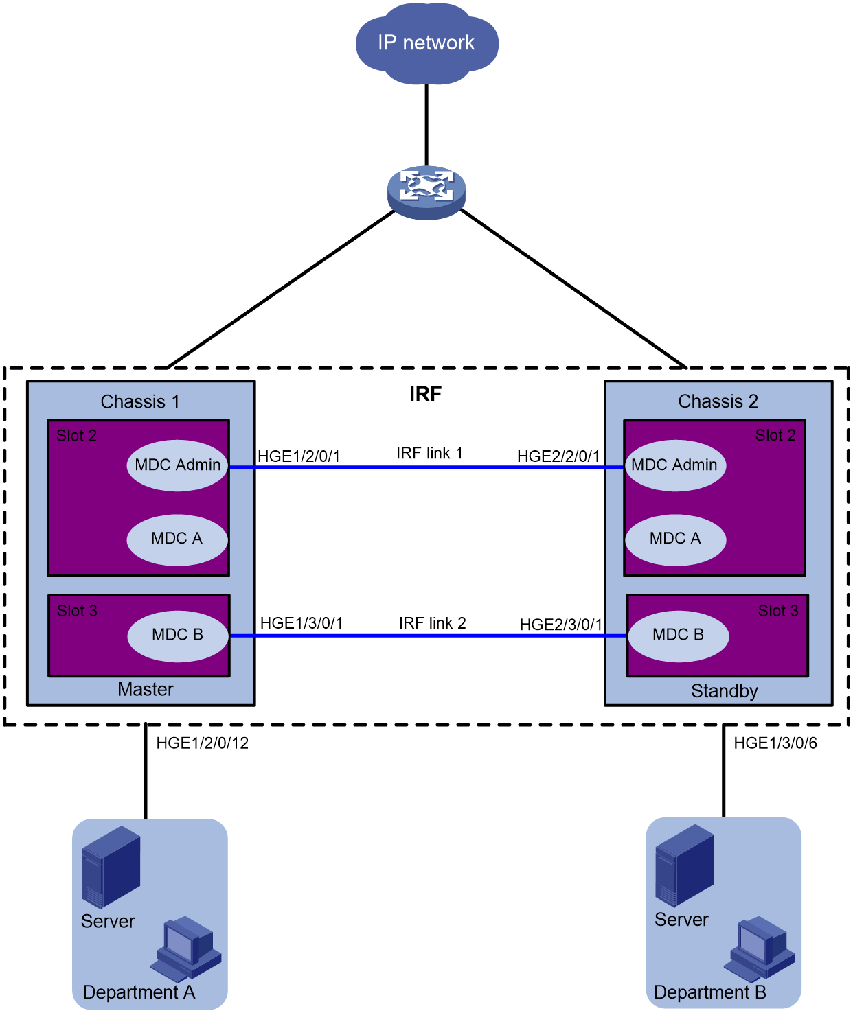
As shown in Figure 4, two departments need to use the IRF fabric to access the Internet. In the IRF fabric, each member device has two LPUs. Each LPU has 12 HGE interfaces.
The two member devices are connected with two IRF links. The IRF port on the master is IRF port 1. The IRF port on the subordinate member is IRF port 2. IRF port 1 is bound with HundredGigE 1/2/0/1 and HundredGigE 1/3/0/1. IRF port 2 is bound with HundredGigE 2/2/0/1 and HundredGigE 2/3/0/1.
Configure two MDCs on the IRF fabric to meet the Internet access requirements of two departments. Assign HundredGigE 1/2/0/7 through HundredGigE 1/2/0/12 and HundredGigE 2/2/0/7 through HundredGigE 2/2/0/12 to MDCA. Assign HundredGigE 1/3/0/1 through HundredGigE 1/3/0/6 and HundredGigE 2/3/0/1 through HundredGigE 2/3/0/6 to MDCB.
Each member device must always have a minimum of one IRF link in up state during the MDC configuration. If you fail to do so, an IRF fabric split occurs. As a best practice, leave IRF physical interfaces to the default MDC if you have enough interface resources. However, the interface resources are limited because the interfaces are grouped. If you have to assign IRF physical interfaces to a non-default MDC, make sure the configuration steps are in the correct order. If not, the IRF physical interfaces might not be able to operate correctly.
To cover both scenarios, one pair of IRF physical interfaces is left to the default MDC and one pair is moved to non-default MDC MDCB in this example.
Procedure
|
|
IMPORTANT: By default, interfaces on the device are disabled (in ADM or Administratively Down state). To have an interface operate, you must use the undo shutdown command to enable that interface. |
1. Create MDCA and MDCB:
# Create MDCA for Department A.
<IRF> system-view
[IRF] mdc MDCA
It will take some time to create MDC...
MDC created successfully.
[IRF-mdc-2-MDCA] quit
The output shows that MDCA is created successfully. As a best practice, make sure MDCA is created successfully before you create MDCB.
# Create MDCB for Department B.
[IRF] mdc MDCB
It will take some time to create MDC...
MDC created successfully.
[IRF-mdc-3-MDCB] quit
The output shows that MDCB is created successfully. As a best practice, make sure MDCB is created successfully before you perform the following tasks.
2. Remove the bindings of HundredGigE 1/2/0/1 and HundredGigE 2/2/0/1 to IRF ports:
|
|
TIP: To avoid IRF fabric split, make sure the other IRF link is in up state while you are performing the following tasks. |
# Shut down HundredGigE 1/2/0/1 and HundredGigE 2/2/0/1.
[IRF] interface range hundredgige 1/2/0/1 hundredgige 2/2/0/1
[IRF-if-range] shutdown
[IRF-if-range] quit
# Remove the binding of HundredGigE 1/2/0/1 to IRF-port 1/1.
[IRF] irf-port 1/1
[IRF-irf-port1/1] undo port group interface HundredGigE1/2/0/1
[IRF-irf-port1/1] quit
# Remove the binding of HundredGigE 2/2/0/1 to IRF-port 2/2.
[IRF] irf-port 2/2
[IRF-irf-port2/2] undo port group interface HundredGigE2/2/0/1
[IRF-irf-port2/2] quit
3. Reclaim the LPU in slot 2 of each member device from the default MDC.
[IRF] mdc Admin
[IRF-mdc-1-Admin] undo location chassis 1 slot 2
The configuration associated with the specified slot of MDC will be lost. Continue? [Y/N]:y
[IRF-mdc-1-Admin] undo location chassis 2 slot 2
The configuration associated with the specified slot of MDC will be lost. Continue? [Y/N]:y
[IRF-mdc-1-Admin] quit
4. Assign resources to MDCA and start MDCA:
# Assign HundredGigE 1/2/0/7 through HundredGigE 1/2/0/12 and HundredGigE 2/2/0/7 through HundredGigE 2/2/0/12 to MDCA.
[IRF] mdc MDCA
[IRF-mdc-2-MDCA] allocate interface hundredgige 1/2/0/7 to hundredgige 1/2/0/12
Configuration of the interfaces will be lost. Continue? [Y/N]:y
Execute the location slot command in this view to make the configuration take effect.
[IRF-mdc-2-MDCA] allocate interface hundredgige 2/2/0/7 to hundredgige 2/2/0/12
Configuration of the interfaces will be lost. Continue? [Y/N]:y
Execute the location slot command in this view to make the configuration take effect.
# Authorize MDCA to use the two LPUs.
[IRF-mdc-2-MDCA] location chassis 1 slot 2
[IRF-mdc-2-MDCA] location chassis 2 slot 2
# Set the CPU weight to 5 for MDCA.
[IRF-mdc-2-MDCA] limit-resource cpu weight 5
# Start MDCA.
[IRF-mdc-2-MDCA] mdc start
It will take some time to start MDC...
MDC started successfully.
[IRF-mdc-2-MDCA] quit
5. Re-authorize the default MDC to use the two LPUs.
[IRF] mdc Admin
[IRF-mdc-1-Admin] location chassis 1 slot 2
[IRF-mdc-1-Admin] location chassis 2 slot 2
[IRF-mdc-1-Admin] quit
6. Rebind HundredGigE 1/2/0/1 and HundredGigE 2/2/0/1 to IRF ports:
# Bind HundredGigE 1/2/0/1 to IRF-port 1/1.
[IRF] irf-port 1/1
[IRF-irf-port1/1] port group interface hundredgige1/2/0/1
[IRF-irf-port1/1] quit
# Bind HundredGigE 2/2/0/1 to IRF-port 2/2.
[IRF] irf-port 2/2
[IRF-irf-port2/2] port group interface hundredgige2/2/0/1
[IRF-irf-port2/2] quit
# Bring up the physical interfaces.
[IRF] interface range hundredgige 1/2/0/1 hundredgige 2/2/0/1
[IRF-if-range] undo shutdown
[IRF-if-range] quit
7. Configure MDCA to enable remote access to MDCA:
# Log in to MDCA from the default MDC. Press Ctrl+D as prompted to stop automatic MDC configuration and access the CLI of MDCA.
[IRF] switchto mdc MDCA
******************************************************************************
* Copyright (c) 2004-2017 New H3C Technologies Co., Ltd. All rights reserved.*
* Without the owner's prior written consent, *
* no decompiling or reverse-engineering shall be allowed. *
******************************************************************************
Automatic configuration is running, press CTRL_D to break or press CTRL_B to
switch back to the default MDC.
<IRF> system-view
# Change the device name to MDCA for easy identification of the MDC.
[IRF] sysname MDCA
# Assign an IP address to the management interface and configure Telnet login.
[MDCA] display interface m-gigabitethernet brief
Brief information on interfaces in route mode:
Link: ADM - administratively down; Stby - standby
Protocol: (s) - spoofing
Interface Link Protocol Primary IP Description
M-GE1/0/0/0 DOWN DOWN --
M-GE1/0/0/1 DOWN DOWN --
M-GE1/0/0/2 UP UP --
M-GE1/0/0/3 DOWN DOWN --
[MDCA] interface m-gigabitethernet 1/0/0/2
[MDCA-M-GigabitEthernet1/0/0/2] ip address 192.168.2.251 24
[MDCA-M-GigabitEthernet1/0/0/2] quit
[MDCA] telnet server enable
[MDCA] user-interface vty 0 63
[MDCA-line-vty0-63] authentication-mode none
[MDCA-line-vty0-63] user-role mdc-admin
# Return to the default MDC.
[MDCA-line-vty0-63] return
<MDCA> switchback
[IRF]
8. Remove the bindings of HundredGigE 1/3/0/1 and HundredGigE 2/3/0/1 to IRF ports:
|
|
TIP: To avoid IRF fabric split, make sure the other IRF link is in up state while you are performing the following tasks. |
# Shut down HundredGigE 1/3/0/1 and HundredGigE 2/3/0/1.
[IRF] interface range hundredgige 1/3/0/1 hundredgige 2/3/0/1
[IRF-if-range] shutdown
[IRF-if-range] quit
# Remove the binding of HundredGigE 1/3/0/1 to IRF-port 1/1.
[IRF] irf-port 1/1
[IRF-irf-port1/1] undo port group interface HundredGigE1/3/0/1
[IRF-irf-port1/1] quit
# Remove the binding of HundredGigE 2/3/0/1 to IRF-port 2/2.
[IRF] irf-port 2/2
[IRF-irf-port2/2] undo port group interface HundredGigE2/3/0/1
[IRF-irf-port2/2] quit
9. Reclaim the LPU in slot 3 of each member device from the default MDC.
[IRF] mdc Admin
[IRF-mdc-1-Admin] undo location chassis 1 slot 3
The configuration associated with the specified slot of MDC will be lost. Continue? [Y/N]:y
[IRF-mdc-1-Admin] undo location chassis 2 slot 3
The configuration associated with the specified slot of MDC will be lost. Continue? [Y/N]:y
[IRF-mdc-1-Admin] quit
10. Assign resources to MDCB and start MDCB:
# Assign HundredGigE 1/3/0/1 through HundredGigE 1/3/0/6 and HundredGigE 2/3/0/1 through HundredGigE 2/3/0/6 to MDCA.
[IRF] mdc MDCB
[IRF-mdc-3-MDCB] allocate interface hundredgige 1/3/0/1 to hundredgige 1/3/0/6
Configuration of the interfaces will be lost. Continue? [Y/N]:y
Execute the location slot command in this view to make the configuration take effect.
[IRF-mdc-3-MDCB] allocate interface hundredgige 2/3/0/1 to hundredgige 2/3/0/6
Configuration of the interfaces will be lost. Continue? [Y/N]:y
Execute the location slot command in this view to make the configuration take effect.
[IRF-mdc-3-MDCB] quit
# Authorize MDCB to use the two LPUs.
[IRF-mdc-3-MDCB] location chassis 1 slot 3
[IRF-mdc-3-MDCB] location chassis 2 slot 3
# Set the CPU weight to 5 for MDCB.
[IRF-mdc-3-MDCB] limit-resource cpu weight 5
# Start MDCB.
[IRF-mdc-3-MDCB] mdc start
It will take some time to start MDC...
MDC started successfully.
[IRF-mdc-3-MDCB] quit
11. Rebind HundredGigE 1/3/0/1 and HundredGigE 2/3/0/1 to IRF ports:
# Log in to MDCB from the default MDC. Press Ctrl+D as prompted to stop automatic MDC configuration and access the CLI of MDCB.
[IRF] switchto mdc MDCB
******************************************************************************
* Copyright (c) 2004-2017 New H3C Technologies Co., Ltd. All rights reserved.*
* Without the owner's prior written consent, *
* no decompiling or reverse-engineering shall be allowed. *
******************************************************************************
Automatic configuration is running, press CTRL_D to break or press CTRL_B to
switch back to the default MDC.
<IRF> system-view
# Change the device name to MDCB for easy identification of the MDC.
[IRF] sysname MDCB
# Shut down HundredGigE 1/3/0/1 and HundredGigE 2/3/0/1.
[MDCB] interface range hundredgige 1/3/0/1 hundredgige 2/3/0/1
[MDCB-if-range] shutdown
[MDCB-if-range] quit
[MDCB] quit
# Return to the default MDC.
<MDCB> switchback
[IRF]
# View the ID of MDCB.
[IRF] display mdc
ID Name Status
1 Admin active
2 MDCA active
3 MDCB active
# Bind HundredGigE 1/3/0/1 to IRF port 1/1.
[IRF] irf-port 1/1
[IRF-irf-port1/1] port group mdc 3 interface hundredgige 1/3/0/1
[IRF-irf-port1/1] quit
# Bind HundredGigE 2/3/0/1 to IRF port 2/2.
[IRF] irf-port 2/2
[IRF-irf-port2/2] port group mdc 3 interface hundredgige 2/3/0/1
[IRF-irf-port2/2] quit
# Log in to MDCB from the default MDC.
[IRF] switchto mdc MDCB
******************************************************************************
* Copyright (c) 2004-2017 New H3C Technologies Co., Ltd. All rights reserved.*
* Without the owner's prior written consent, *
* no decompiling or reverse-engineering shall be allowed. *
******************************************************************************
<MDCB> system-view
# Bring up HundredGigE 1/3/0/1 and HundredGigE 2/3/0/1.
[MDCB] interface range hundredgige 1/3/0/1 hundredgige 2/3/0/1
[MDCB-if-range] undo shutdown
[MDCB-if-range] quit
# Assign an IP address to the management interface and configure Telnet login.
[MDCB] display interface m-gigabitethernet brief
Brief information on interfaces in route mode:
Link: ADM - administratively down; Stby - standby
Protocol: (s) - spoofing
Interface Link Protocol Primary IP Description
M-GE1/0/0/0 DOWN DOWN --
M-GE1/0/0/1 DOWN DOWN --
M-GE1/0/0/2 UP UP --
M-GE1/0/0/3 DOWN DOWN --
[MDCB] interface m-gigabitethernet 1/0/0/2
[MDCB-M-GigabitEthernet1/0/0/2] ip address 192.168.1.252 24
[MDCB-M-GigabitEthernet1/0/0/2] quit
[MDCB] telnet server enable
[MDCB] user-interface vty 0 63
[MDCB-line-vty0-63] authentication-mode none
[MDCB-line-vty0-63] user-role mdc-admin
[MDCB-line-vty0-63] return
# Return to the default MDC.
<MDCB> switchback
[IRF]
Verifying the configuration
1. Verify that the MDCs exist and are operating correctly.
[IRF] display mdc
ID Name Status
1 Admin active
2 MDCA active
3 MDCB active
The output shows that the MDCs have been created and are operating correctly.
2. Display IRF link information.
[IRF] display irf link
Member 1
IRF Port Interface Status
1 HundredGigE1/2/0/1(MDC1) UP
HundredGigE1/3/0/1(MDC3) UP
2 disable --
Member 2
IRF Port Interface Status
1 disable --
2 HundredGigE2/2/0/1(MDC1) UP
HundredGigE2/3/0/1(MDC3) UP
The output shows that two IRF links exist and are in up state. One IRF link is on the default MDC, and the other IRF link is on MDCB.
3. Log in to MDCA as an administrator of Department A. View the running configuration of the MDC.
C:\> telnet 192.168.1.251
******************************************************************************
* Copyright (c) 2004-2017 New H3C Technologies Co., Ltd. All rights reserved.*
* Without the owner's prior written consent, *
* no decompiling or reverse-engineering shall be allowed. *
******************************************************************************
<MDCA> display current-configuration
...
