- Table of Contents
- Related Documents
-
| Title | Size | Download |
|---|---|---|
| 01-Text | 569.69 KB |
Power Module Installation and Removal
Installing and Removing a Power Module
Connecting and Disconnecting the AC Power Cords
Introduction
The PSR2800-ACV is a built-in power module with AC input and DC output. It can provide the device with both system power and PoE power, which can be controlled through separate switches.
Table 1 Features of the PSR2800-ACV power module
|
Feature |
Description |
|
Protection functions |
Support input under-voltage protection, output over-voltage protection, short-circuit protection, over-current protection, and overheat protection |
|
Hot swap support |
Support hot swap with the power switch turned off while the device is in operation |
|
1+1 hot backup support |
Support 1 + 1 hot backup and current sharing |
|
|
CAUTION: Do not use different types of power modules in the same device. |
Schematic View
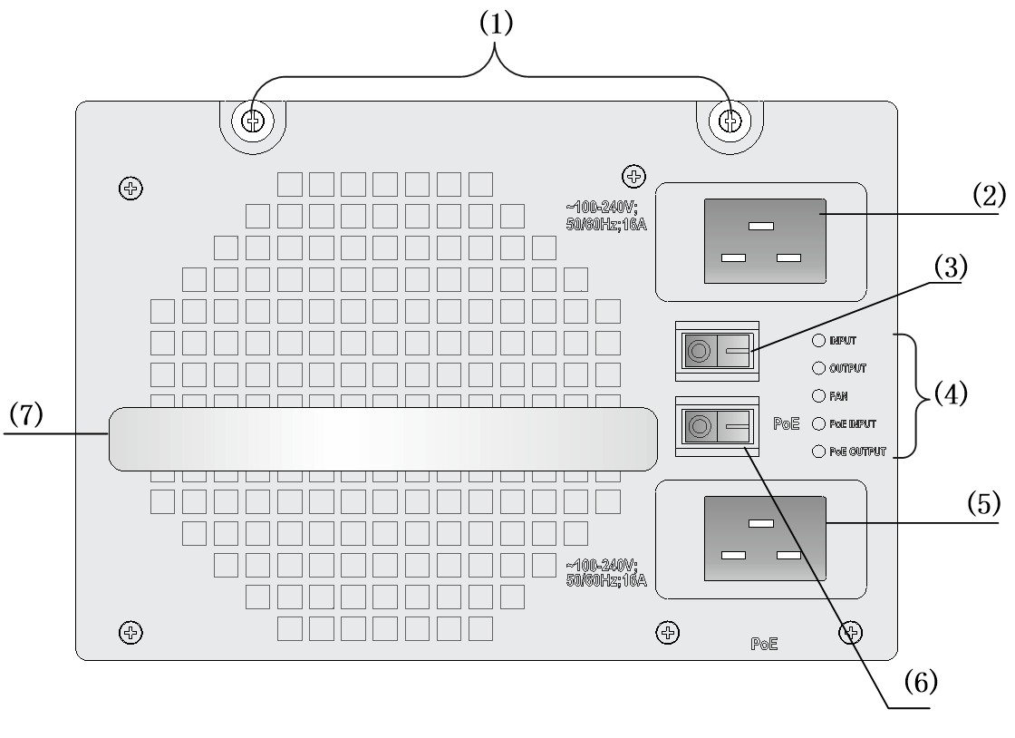
Figure 1 Schematic view of the PSR2800-ACV power module
|
(1) Captive screws |
(2) System power socket |
|
(3) System power switch |
(4) Status LEDs |
|
(5) PoE socket |
(6) PoE switch |
|
(7) Power module handle |
|
The PSR2800-ACV can provide both system power and PoE power outputs. The upper switch (callout (4) in Figure 1) is used to control the output of the entire power supply system, while the lower switch (callout (8) in Figure 1) is used to control the PoE power output.
|
|
CAUTION: Turn off the PoE switch if PoE power supply is not required by the device. For more information, see the installation guide or hardware information and specifications for the device. |
The PoE power can be used both for power supply of PoE-powered devices and for auxiliary power supply of devices that do not support PoE. For details, refer to the corresponding installation manuals.
Specifications
Table 2 Technical specifications for the PSR2800-ACV power module
|
Item |
Specifications |
|
|
Rated voltage range |
100 VAC to 240 VAC; 50 Hz or 60 Hz |
|
|
Maximum output current |
117 A (System power) |
|
|
117 A (PoE power) |
||
|
Maximum system output power |
1150 W (110 VAC) |
|
|
1400 W (220 VAC) |
||
|
Maximum PoE output power |
1150 W (110 VAC) |
|
|
1400 W (220 VAC) |
||
|
Dimensions (H × W × D) |
128 × 196 × 380 mm (5.04 × 7.72 × 14.96 in.) |
|
|
Operating temperature |
0~55℃ |
|
|
Storage temperature |
-40~70℃ |
|
Status LEDs
The PSR2800-ACV power module has five red/green status LEDs: INPUT, OUTPUT, FAN, PoE INPUT, and PoE OUTPUT.
The PSR2800-ACV power module can provide PoE only when the system power output is normal.
Table 3 describes the colors and working status of the five LEDs in different cases.
Table 3 Description of LEDs on the PSR2800-ACV power module
|
LED |
Color/status |
Meaning |
|
INPUT |
Off |
No system power input is present. |
|
Green |
The system power input is normal. |
|
|
Red |
The system power input is abnormal. |
|
|
OUTPUT |
Off |
No system power input is present. |
|
Green |
The system power output is normal. |
|
|
Red |
The power switch is in the OFF position. |
|
|
Power alarm (output short circuit, output over-current, output over-voltage, or overheat occurred to the power module, and the power module took a self-protection action). |
||
|
FAN |
Off |
No system power input is present. |
|
Green |
The power module fan works normally. |
|
|
Red |
The system switch is in the OFF position. |
|
|
The power module fan is faulty (The power module takes a self-protection action and stops power output two seconds after the fan fails). |
||
|
PoE INPUT |
Off |
No PoE power input is present. |
|
Green |
The PoE power input is normal. |
|
|
Red |
The PoE power input is abnormal. |
|
|
PoE OUTPUT |
Off |
No PoE power input is present. |
|
Green |
The power output is normal. |
|
|
Red |
The power switch is in the OFF position. |
|
|
Power alarm (output short circuit, output over-current, output over-voltage, or overheat occurred to the power module, and the power module took a self-protection action). |
|
|
CAUTION: Do not turn on and off the power switch too frequently. After turning off the power switch, wait at least 30 seconds before turning it on again. |
Power Module Installation and Removal
When installing or removing a power module be sure to follow the sequence shown in Figure 2 and Figure 4.
Figure 2 Flow chart for installing a power module
![]()
Figure 3 Flow chart for removing a power module
![]()
Installing and Removing a Power Module
You need to prepare the tools for installing or removing power modules.
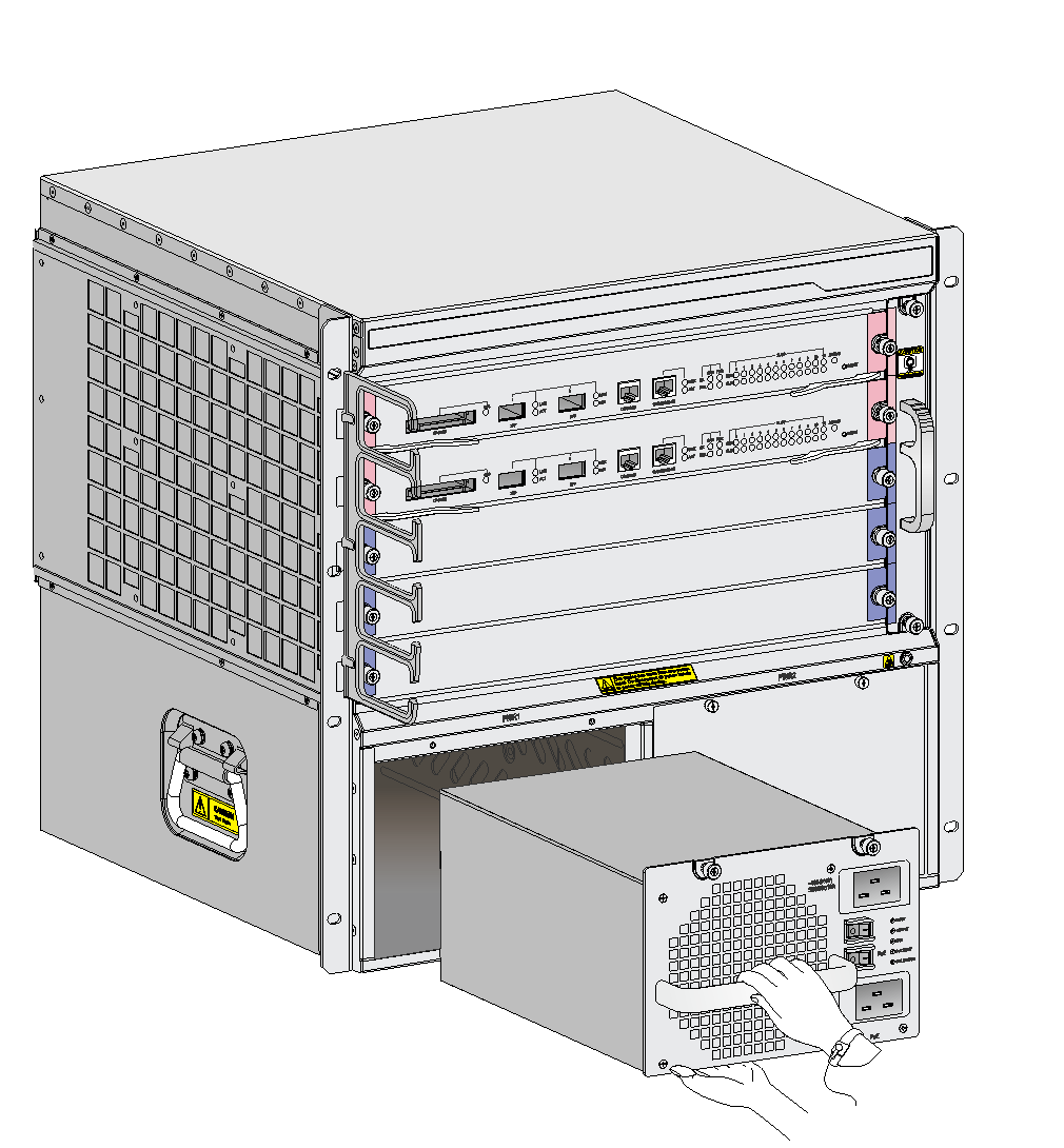
Figure 4 Install/remove the PSR2800-ACV power module
Installing a Power Module
Follow these steps to install the PSR2800-ACV power module:
1. Put on an ESD-preventive wrist strap.
2. Take out the PSR2800-ACV power module out of its package.
3. With one hand grasping the handle of the power module and the other holding the bottom, insert the power module along the guide rails into the chassis until it snaps into the backplane connector.
|
|
CAUTION: · You need to follow the forward inertia of the power module when inserting it into the chassis. · To prevent damage to the connectors on the power module and the backplane, first pull the power module out and then insert it again in the case of any misalignment. |
4. Tighten the captive screws with a No. 1 Phillips screwdriver to fix the power module in the chassis.
|
|
CAUTION: If the captive screws cannot be tightened, check whether the power module is properly installed. |
Removing a Power Module
Follow these steps to remove the PSR2800-ACV power module:
1. Put on an ESD-preventive wrist strap.
2. Loosen the captive screws on the power module with a No. 1 Phillips screwdriver.
3. With one hand grasping the handle of the power module, pull the power module part way out of the chassis.
4. With this hand still grasping the handle and the other holding the bottom, pull the power module slowly out of the chassis.
|
|
CAUTION: Before removing the power module, disconnect the power supply and remove the AC power cords. |
Connecting and Disconnecting the AC Power Cords
The following describes how to connect a power cable. To disconnect a power cable, follow the inverse order.
When connecting and disconnecting power cables, check that the power switch is in the OFF position.
Connecting the AC Power Cords
The following describes how to connect the system power cord. You can connect the PoE power cord in the way you connect the system power cord.
The accessories provided with the power module are different in batches. If a releasable cable tie is provided with the power module, follow this procedure to connect and secure the power cord.
Figure 5 Figure 5 Using a releasable cable tie to secure Connect the AC power cord
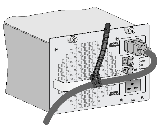
1. Unpack the power cord, and verify that the power cord model is correct.
2. Connect the power cord to the power receptacle on the power module, and ensure a good contact.
3. Use a cable tie to secure the power cord to the handle of the power module.
4. Connect the other end of the power cord to the AC power source.
If a power cord retention clip is provided with the power module, follow this procedure to connect and secure the power cord.
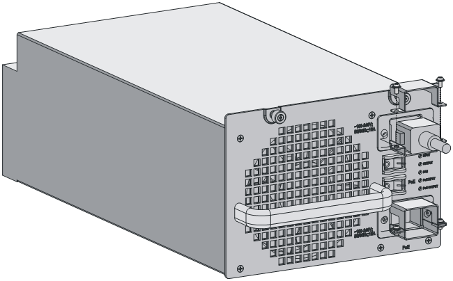
Figure 6 Using a power cord retention clip to secure Connect the AC power cord
Follow these steps to connect the system power cord:
1. Use a No. 1 Phillips screwdriver to remove the screws from the power cord retention clip and remove the upper part of the power cord retention device.
2. Plug one end of the power cord shipped with the power module into the system power socket, and then fix the removed part of the power cord retention clip to the lower part to prevent a falloff.
3. Plug the other end into the AC power socket strip of the AC mains.
